a comprehensive overview on the structure and comparison of magnetic properties of nanocrystalline...
TRANSCRIPT

Review
A comprehensive overview on the structure and comparisonof magnetic properties of nanocrystalline synthesizedby a thermal treatment method
Mahmoud Goodarz Naseri a,n, M.K. Halimah b, Arash Dehzangi c, Ahmad Kamalianfar d,Elias B. Saion b, Burhanuddin Y. Majlis c
a Department of Physics, Faculty of Science, Malayer University, Malayer, Iranb Department of Physics, Universiti Putra Malaysia, 43400 UPM Serdang, Selangor, Malaysiac Institute of Microengineering and Nanoelectronics (IMEN), Universiti Kebangsaan Malaysia, 43600 Bangi, Selangor, Malaysiad Department of Physics, Jahrom University, Jahrom, Iran
a r t i c l e i n f o
Article history:Received 14 November 2011Received in revised form22 October 2013Accepted 7 November 2013Available online 25 November 2013
Keywords:A. NanostructuresC. Infrared spectroscopyC. Thermo-gravimetric analysis (TGA)C. X-ray diffractionD. Electron paramagnetic resonance (EPR)
a b s t r a c t
This study reports the simple synthesis of MFe2O4 (where M¼Zn, Mn and Co) nanostructures by athermal treatment method, followed by calcination at various temperatures from 723 to 873 K. Poly(vinylpyrrolidon) (PVP) was used as a capping agent to stabilize the particles and prevent them fromagglomeration. The pyrolytic behaviors of the polymeric precursor were analyzed by use of simultaneousthermo-gravimetry analyses (TGA) and derivative thermo-gravimetry (DTG) analyses. The characteriza-tion studies were conducted by X-ray diffraction (XRD) and transmission electron microscopy (TEM).Fourier transform infrared spectroscopy (FT-IR) confirmed the presence of metal oxide bands for all thecalcined samples. Magnetic properties were demonstrated by a vibrating sample magnetometer (VSM),which displayed that the calcined samples exhibited different types of magnetic behavior. The presentstudy also substantiated that magnetic properties of ferrite nanoparticles prepared by the thermaltreatment method, from viewing microstructures of them, can be explained as the results of the twoimportant factors: cation distribution and impurity phase of α-Fe2O3. These two factors are subcategoryof the preparation method which is related to macrostructure of ferrite. Electron paramagnetic resonance(EPR) spectroscopy showed the existence of unpaired electrons ZnFe2O4 and MnFe2O4 nanoparticleswhile it did not exhibit resonance signal for CoFe2O4 nanoparticles.
& 2013 Elsevier Ltd. All rights reserved.
Contents
1. Introduction . . . . . . . . . . . . . . . . . . . . . . . . . . . . . . . . . . . . . . . . . . . . . . . . . . . . . . . . . . . . . . . . . . . . . . . . . . . . . . . . . . . . . . . . . . . . . . . . . . . . . . . . 3162. Experimental . . . . . . . . . . . . . . . . . . . . . . . . . . . . . . . . . . . . . . . . . . . . . . . . . . . . . . . . . . . . . . . . . . . . . . . . . . . . . . . . . . . . . . . . . . . . . . . . . . . . . . . 316
2.1. Materials . . . . . . . . . . . . . . . . . . . . . . . . . . . . . . . . . . . . . . . . . . . . . . . . . . . . . . . . . . . . . . . . . . . . . . . . . . . . . . . . . . . . . . . . . . . . . . . . . . . . 3162.2. Characterization. . . . . . . . . . . . . . . . . . . . . . . . . . . . . . . . . . . . . . . . . . . . . . . . . . . . . . . . . . . . . . . . . . . . . . . . . . . . . . . . . . . . . . . . . . . . . . . 316
3. Results and discussion. . . . . . . . . . . . . . . . . . . . . . . . . . . . . . . . . . . . . . . . . . . . . . . . . . . . . . . . . . . . . . . . . . . . . . . . . . . . . . . . . . . . . . . . . . . . . . . . 3163.1. Thermal analyses of PVP . . . . . . . . . . . . . . . . . . . . . . . . . . . . . . . . . . . . . . . . . . . . . . . . . . . . . . . . . . . . . . . . . . . . . . . . . . . . . . . . . . . . . . . . 3163.2. Mechanism of interaction of PVP and metal ions in synthesize of metal ferrite nanoparticles. . . . . . . . . . . . . . . . . . . . . . . . . . . . . . . . . 3163.3. Phase composition and morphology of precursors and metal ferrite nanoparticles . . . . . . . . . . . . . . . . . . . . . . . . . . . . . . . . . . . . . . . . . 3183.4. Magnetic properties of precursors and metal ferrite nanoparticles . . . . . . . . . . . . . . . . . . . . . . . . . . . . . . . . . . . . . . . . . . . . . . . . . . . . . . 323
3.4.1. Calcination temperature . . . . . . . . . . . . . . . . . . . . . . . . . . . . . . . . . . . . . . . . . . . . . . . . . . . . . . . . . . . . . . . . . . . . . . . . . . . . . . . . . 3243.4.2. Heating rate of calcination . . . . . . . . . . . . . . . . . . . . . . . . . . . . . . . . . . . . . . . . . . . . . . . . . . . . . . . . . . . . . . . . . . . . . . . . . . . . . . . 324
3.5. Magnetic resonance study of metal ferrite nanoparticles . . . . . . . . . . . . . . . . . . . . . . . . . . . . . . . . . . . . . . . . . . . . . . . . . . . . . . . . . . . . . . 3254. Conclusion . . . . . . . . . . . . . . . . . . . . . . . . . . . . . . . . . . . . . . . . . . . . . . . . . . . . . . . . . . . . . . . . . . . . . . . . . . . . . . . . . . . . . . . . . . . . . . . . . . . . . . . . . 325Acknowledgment . . . . . . . . . . . . . . . . . . . . . . . . . . . . . . . . . . . . . . . . . . . . . . . . . . . . . . . . . . . . . . . . . . . . . . . . . . . . . . . . . . . . . . . . . . . . . . . . . . . . . . . 326References . . . . . . . . . . . . . . . . . . . . . . . . . . . . . . . . . . . . . . . . . . . . . . . . . . . . . . . . . . . . . . . . . . . . . . . . . . . . . . . . . . . . . . . . . . . . . . . . . . . . . . . . . . . . . 326
Contents lists available at ScienceDirect
journal homepage: www.elsevier.com/locate/jpcs
Journal of Physics and Chemistry of Solids
0022-3697/$ - see front matter & 2013 Elsevier Ltd. All rights reserved.http://dx.doi.org/10.1016/j.jpcs.2013.11.004
n Corresponding author. Tel.: þ60 142698153; fax: þ60 3 89454454.E-mail address: [email protected] (M.G. Naseri).
Journal of Physics and Chemistry of Solids 75 (2014) 315–327

1. Introduction
Nanoscience and nanotechnology are involved in the manip-ulation of materials and the creation of structures and systems atthe nanometer scale. As a result, nanomaterials have attractedmuch attention because of their surface effect (large surface-to-volume ratio) and quantum confinement effects (size-dependentproperties). These factors affect their physical and chemicalproperties, which differ from the properties of their molecularand bulk counterparts. Nanoparticles with zero-dimensionalnanostructures are generally classified according to their composi-tions, i.e., metal oxides, noble metals, transition metals, magneticmetals, and semiconductor nanomaterials or quantum dots. Likeall nanostructures, magnetic metals nanoparticles are dependenton their size and shape. Currently, magnetic oxide nanoparticlesare attracting significant interest due to their extensive applica-tions, ranging from fundamental research to industrial use. Spinelnanocrystals are regarded as two of the most important inorganicnanomaterials because of their electronic, optical, electrical, mag-netic, and catalytic properties. Spinel have the structure AB2O4 inwhich A and B display tetrahedral and octahedral cation sites,respectively, and O indicates the oxygen anion site. Metal spinelferrite nanoparticles have the general molecular formula MFe2O4
(e.g., M¼Ni, Zn, Mn, Co, or Mg), and they have a face-centered-cubic (fcc) close packing structure. Among the spinel ferritescompounds, zinc ferrite, manganese ferrite and cobalt ferrite havebeen studied extensively due to their different structures com-posed of normal, mixed and inverse spinel structures respectivelyand their high electromagnetic performance, excellent chemicalstability, mechanical hardness, low coercivity, and moderatesaturation magnetization, which make it a good contender forthe application as soft magnets and low-loss materials at highfrequencies [1–3]. These properties are dependent on the chemicalcomposition and microstructural characteristics in which theparticle size and shape might be controlled in the fabricationprocesses. In order to achieve materials that have the desiredphysical and chemical properties, the preparation of spinel ferritesnanocrystals through different routes has become an essentialfocus of the related research and development activities. Variousfabrication methods to prepare spinel ferrites nanocrystals havebeen reported, e.g., citrate–gel methods [4], the ball-millingtechnique [5], co-precipitation [6], polymeric assisted route [7]the hydrothermal method [8], the reverse micelles process [9], andthe micro-emulsion method [10]. Various precipitation agentshave been used to produce specific size and shape spinel ferritesnanocrystals, e.g., metal hydroxide in the co-precipitation method,surfactant and ammonia in the reverse micelles process andvarious micro-emulsion methods, and organic matrices in thesol–gel method. Most of these methods have achieved particlesof the required sizes and shapes, but they are difficult to employon a large scale because of their expensive and complicatedprocedures, high reaction temperatures, long reaction times, toxicreagents and by-products, and their potential harm to the envir-onment. In the present study, spinel ferrites nanocrystals withdifferent structures were prepared from an aqueous solutioncontaining metal nitrates, poly(vinyl pyrrolidon), and deionizedwater using a low temperature thermal treatment method, fol-lowed by grinding and calcination. No other chemicals were addedto the solution. This method is environmentally friendly in that itneither uses nor produces toxic substances, and it offers theadvantages of simplicity, low cost, and low reaction temperatures.The textural and morphological characteristics of the spinelferrites nanocrystals we prepared were studied with varioustechniques to determine the influence of calcination temperatureon the crystallization, morphology, and particle size distribution ofthe nanocrystals and to explore other parameters of interest.
2. Experimental
2.1. Materials
In this study, metal nitrate reagents, poly(vinyl pyrrolidon) (PVP),and deionized water were used as precursors. In addition, a cappingagent to control the agglomeration of the particles and a solventwere used. Iron nitrate, Fe(NO3)3 �9H2O, zinc nitrate, Zn(NO3)2 �6H2O, manganese nitrate, Mn(NO3)2 �6H2O and cobalt nitrate, Co(NO3)2 �6H2O, were purchased from Acros Organics with a purityexceeding 99%. PVP (MW¼29,000) was purchased from Sigma Aldrichand was used without further purification. An aqueous solution of PVPwas prepared by dissolving of polymer in 100 ml of deionized water at363 K, before mixing 0.2 mmol iron nitrate and 0.1 mmol metal nitrate(Fe:M¼2:1) into the polymer solution and constantly stirring for 2 husing a magnetic stirrer until a colorless, transparent solution wasobtained. A glass electrode was used to determine the pH of thesolution, which ranged 1–2. The mixed solution was poured into aglass Petri dish and heated at 353 K in an oven for 24 h to evaporatethe water. The dried, orange, solid zinc ferrite that remained wascrushed and ground in a mortar to form powder. The calcinations ofthe powders were conducted at 723, 773, 823, and 873 K for 3 h forthe decomposition of organic compounds and the crystallization of thenanocrystals. (Note that 3 h was the minimum time that allowed thecrystallization to be completed). The processing steps employedseparately for the synthesis of each ferrite nanoparticles.
2.2. Characterization
The structure of the ZnFe2O4, MnFe2O4 and CoFe2O4 nanoparticleswere characterized by the XRD technique using a Shimadzu diffractmeter model XRD 6000 employing Cu Kα (0.154 nm) radiation togenerate diffraction patterns from powder crystalline samples atambient temperature in a 2θ range of 10–701. The microstructureand particle size of the nanocrystals were determined from Transmis-sion Electron Microscopy (TEM) images that were obtained by using aJEOL 2010F UHR version electronmicroscope at an accelerating voltageof 200 kV. FT-IR spectra were recorded using a PerkinElmer FT-IRmodel 1650 spectrometer. Before recording spectra, the samples wereplaced on a Universal ATR Sampling Accessory (diamond coated withCsI) and pressed, and then the spectra were recorded. Magnetizationmeasurements were conducted using a vibrating sample magnet-ometer (VSM) (Lake Shore 4700) at room temperature with maximummagnetic field of 15 kOe.
3. Results and discussion
3.1. Thermal analyses of PVP
Fig. 1 shows the simultaneous thermo-gravimetry (TG) and deri-vative thermo-gravimetry analyses (DTG) of PVP. This thermogramshowed that the PVP was thermally stable until 673 K and that themaximum decomposition rate occurred around 778 K. These resultswere supported by the FT-IR analysis (Section 3.3) that showed thatthe samples calcined at 873 K (ZnFe2O4, MnFe2O4) and at 773 K(CoFe2O4) did not show any absorption band belonging to PVP ornitrate anions. So, this confirmed that, at these temperatures, themagnetic nanoparticles were pure.
It is worth noting that several authors reported the thermaldegradation of PVP exhibits only one mass loss [11–13].
3.2. Mechanism of interaction of PVP and metal ions in synthesizeof metal ferrite nanoparticles
Interactions between the PVP capping agent [14] and metal ionsare shown schematically in Fig. 2. We have shown the Metal (II)
M.G. Naseri et al. / Journal of Physics and Chemistry of Solids 75 (2014) 315–327316

(e.g. Zn, Mn and Co) and iron (III) ions which are bound by thestrong ionic bonds between the metallic ions and the amide groupin a polymeric chain. PVP acts as a stabilizer for dissolved metallicsalts through steric and electrostatic stabilization of the amidegroups of the pyrolidine rings and the methylene groups. Initially,the PVP stabilizer may decompose to as limited extent, therebyproducing shorter polymer chains that are capped when they areadsorbed onto the surfaces of metallic ions [15]. The metallic ions,which are well dispersed in the cavities and networks, are createdas a result of the shorter polymer chains. These mechanismscontinue until they are terminated by the drying step. The influenceof PVP is not restricted only to the solution and the drying step; PVPalso affects the formation of the nuclei (i.e., nucleation) of the metalferrite nanoparticles in the calcination step. In this step, the smallnanoparticles with high surface energy levels would become largervia the Ostwald ripening process [16] without the presence ofPVP, disrupts steric hindrance, thereby preventing their aggrega-tion. Steric hindrance is a phenomenon that is attributed to large
Fig. 1. Thermal analyses of the polymeric precursor which obtained by TG-DTGtechnique.
Drying 2Fe3+,
M+2, 8NO3-
H2O, 2Fe3+,
M+2, 8NO3-
2Fe3+,
M+2, 8NO3-
MFe2O4MFe2O4 MFe2O4MFe2O4
NucleationPVP removing
H2O, 2Fe3+,
M+2, 8NO3-
N
N
N
N
N
NO O
O
O
O
On
Fe3+
M2+
NO3-
H OH
HO H
HO H
HO H
HO H
H OH
HO H
HOH
N O N O
H OH
Calcination
Fig. 2. The proposed mechanism of interactions between PVP and metal ions in the formation of the metal ferrites nanoparticles.
M.G. Naseri et al. / Journal of Physics and Chemistry of Solids 75 (2014) 315–327 317

molecular weight (410,000) and the repulsive forces acting amongthe polyvinyl groups [17,18]. These interactions are similar to thestabilization of metallic nanoparticles, i.e., silver and gold [19,20].
3.3. Phase composition and morphology of precursors and metalferrite nanoparticles
XRD and FT-IR were used to characterize the precursors and ferritenanoparticles calcined at 723, 773, 823 and 873 K. The XRD diffractionpatterns of the precursor and metal ferrite nanoparticles are shown inFig. 3. A broad peak occurred for all samples in the precursor, whichdoes not have sharp diffraction patterns and is still amorphous. Thecalcined patterns show the reflection planes (111), (220), (311), (222),(400), (331), (422), (511), and (440), which confirm the presence ofsingle-phase in ZnFe2O4, MnFe2O4 and CoFe2O4 with a face-centeredcubic structure [21–23]. Except for the impure phases of α-Fe2O3 (forall the metal ferrite nanoparticles shown in Fig. 3a–c) and ZnO (for thezinc ferrite nanopaticles shown in Fig. 3a), which occur naturally ashematite and zincite, respectively [21–24], the remaining peakscorrespond to the standard pattern of ZnFe2O4 (cubic, space group:Fd3m, Z¼8; ICDD PDF: 22-1012), MnFe2O4 (cubic, space group: Fd3m,Z¼8; ICDD PDF: 73-1964) and CoFe2O4 (cubic, space group: Fd3m,Z¼8; ICDD PDF: 22-1086)[21–23]. It is worth noting that although the
samples were not similar (CoFe2O4, MnFe2O4 and ZnFe2O4) but all ofthem had same phase (cubic phase).
The results obtained from XRD were analyzed using theChekcell program, which calculated lattice parameters of thesamples calcined at 723, 773, 823, and 873 K (Table 1). XRD resultswere analyzed by the Scherrer formula
D¼ 0:9λ=ðβ cos θÞ; ð1Þ
where D is the crystallite size (nm), β is the full width of thediffraction line at half the maximum intensity measured inradians, λ is X-ray wavelength, and θ is the Bragg angle [25]. Thisformula was used to estimate the average particle sizes, whichranged in Table 1.
Fig. 4 shows the FT-IR spectrum of the precursor and calcinedsamples in the wave-number range between 280 and 4000 cm�1.The IR spectra of all calcined samples show the two principleabsorption bands in the range of 300–600 cm�1. These twovibration bands Fe2O and M2O are corresponded to theintrinsic lattice vibrations of octahedral and tetrahedral coordina-tion compounds in the spinel structure, respectively [26]. Thebands with peaks around 670 and 850 cm�1 were assigned to theformation vibration of C–NQO bending and the C–C ring. Thebands in the range of 1200–1250 cm�1 was associated with C–N
Fig. 3. XRD patterns of precursors and metal ferrite nanoparicles of (a) ZnFe2O4, (b) MnFe2O4 and (c) CoFe2O4 calcined at 723, 773, 823 and 873 K.
M.G. Naseri et al. / Journal of Physics and Chemistry of Solids 75 (2014) 315–327318

stretching vibration, and the appearance of the bands in the rangeof 1350 to 1450 cm�1 was attributed to C–H bending vibrationfrom the methylene groups. Finally, there were bands in the region1600–1800 cm�1 and around 3400–3500 cm�1, which were asso-ciated with CQO stretching vibration and N–H or O–H stretchingvibration, respectively [27]. The vibrational spectra of the absorp-tion bands of pure ZnFe2O4 and MnFe2O4 nanoparticles were
observed at 388 and 541 cm�1, and at 404, 502, and 556 cm�1
for the samples calcined at 873 K (shown in Fig. 4a and b). In thesetwo ferrite nanoparticles, at the lower temperature of 873 K,however, there was still traces of broadband absorption peaks at1497, 1761 and 3504 cm�1 due to traces of adsorbed or atmo-spheric CO2 and O–H stretching vibration, respectively while inCoFe2O4 nanoparticles (Fig. 4c), at the lower temperature of 773 K,
Table 1Summery of variation of particle sizes, lattice parameters, saturation magnetization and coercivity field with temperature calcinations for metal ferrite nanoparticles calcinedat 723, 773, 823 and 873 K.
SpecimensMeFe2O4
Calcinationtemperature (K)
Average particlesize XRD (nm)
Average particlesize TEM (nm)
Lattice parameter (nm) Saturation magnetizationMs (emu/g)
Coercivityfield Hc (Oe)
ZnFerrite 1 723 21 1777 0.8498 4.49 18ZnFerrite 2 773 24 2272.5 0.8468 2.66 33ZnFerrite 3 823 31 2775 0.8471 1.81 41ZnFerrite 4 873 33 31711 0.8479 0.74 42MnFerrite 1 723 15 1274 0.8524 3.06 37MnFerrite 2 773 17 1572 0.8577 6.31 24MnFerrite 3 823 20 1775 0.8558 7.96 20MnFerrite 4 873 23 2274 0.8537 15.78 19CoFerrite 1 723 15.5 1478 0.8356 2.14 823CoFerrite 2 773 16.5 1776 0.8348 12.86 1225CoFerrite 3 823 34 2979 0.8375 18.02 1791CoFerrite 4 873 37 3475 0.8368 23.47 1163
Fig. 4. FT-IR spectra of precursors and metal ferrite nanoparicles of (a) ZnFe2O4, (b) MnFe2O4 and (c) CoFe2O4 calcined at 723, 773, 823 and 873 K.
M.G. Naseri et al. / Journal of Physics and Chemistry of Solids 75 (2014) 315–327 319
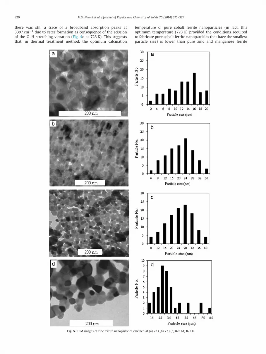
there was still a trace of a broadband absorption peaks at3397 cm�1 due to ester formation as consequence of the scissionof the O–H stretching vibration (Fig. 4c at 723 K). This suggeststhat, in thermal treatment method, the optimum calcination
temperature of pure cobalt ferrite nanoparticles (in fact, thisoptimum temperature (773 K) provided the conditions requiredto fabricate pure cobalt ferrite nanoparticles that have the smallestparticle size) is lower than pure zinc and manganese ferrite
Fig. 5. TEM images of zinc ferrite nanoparticles calcined at (a) 723 (b) 773 (c) 823 (d) 873 K.
M.G. Naseri et al. / Journal of Physics and Chemistry of Solids 75 (2014) 315–327320

nanoparticles with optimum temperature at 873 K [28–30]. This IRanalysis was very useful for establishing the calcination tempera-ture because it removed unwanted organic materials that maypollute the crystal lattice during preparation.
The TEM images (Figs. 5–7) show the size, shape, distributionand particle size distribution histograms of ZnFe2O4, MnFe2O4 andCoFe2O4 nanoparticles at different calcination temperatures from723 to 873 K. The results indicate that the samples prepared by the
Fig. 6. TEM images of manganese ferrite nanoparticles calcined at (a) 723 (b) 773 (c) 823 and (d) 873 K.
M.G. Naseri et al. / Journal of Physics and Chemistry of Solids 75 (2014) 315–327 321

thermal treatment method were uniform in morphology andparticle size distribution. The average particle size of the ZnFe2O4,MnFe2O4 and CoFe2O4 nanoparticles were determined by TEMwhich increased with the calcinations temperature and they hadgood agreement with XRD results (Table 1). This suggested that
several neighboring particles fused together to increase theparticle size by the melting of their surfaces [31]. Particle sizeenlargement due to grain growth has been observed previously inzinc, manganese and cobalt ferrite systems at higher calcinationtemperatures [28–30].
Fig. 7. TEM images of cobalt ferrite nanoparticles calcined at (a) 723 (b) 773 (c) 823 and (d) 873 K.
M.G. Naseri et al. / Journal of Physics and Chemistry of Solids 75 (2014) 315–327322

3.4. Magnetic properties of precursors and metal ferritenanoparticles
The room temperature (300 K) magnetic properties of theprepared precursors and MFe2O4 nanoparticles calcined at differ-ent temperatures were investigated by the VSM technique in therange of approximately �15 to þ15 kOe. Except for the precursorswhich were non-magnetic material, the calcined samples exhib-ited different magnetic behaviors. Fig. 8 shows the magnetizationcurves of precursor and ZnFe2O4 nanoparticles at (a) 723 (b) 773(c) 823 and (d) 873 K. Table 1 provides the values of saturationmagnetization (Ms) of the calcined samples, along with calcina-tions temperatures and particle sizes. These data make it clear thatdifferent parameters were responsible for the saturation magne-tization decreasing from 4.49 to 0.74 emu/g when the particle sizeincreased from 17 to 31 nm. Cation inversion is one of theparameters that can be effective in the variation of the magneticproperties of zinc ferrite nanoparticles from the properties of thebulk form of the same material. In bulk form, zinc ferrite has anormal spinel structure in which all Zn2þ ions are in A sites andFe3þ ions are distributed in B sites [32]. However, in bulk, zincferrite only occurs in intra-sub-lattice (B–B) exchange interactions,and it does not have intra-sub-lattice (A–A) exchange interactionsor inter-sub-lattice (A–B) super-exchange interactions [33]. Inter-sub-lattice (A–B) super-exchange interactions of the cations aremuch stronger than the (A–A) and (B–B) interactions [4]. Due tothe cation inversion, which originates from thermal and mechan-ical treatment [24], the structure of ZnFe2O4 transfers from anormal spinel structure to a mixed spinel structure [33]. Thiscation inversion causes the zinc ferrite nanoparticles to experienceinter-sub-lattice (A–B) super-exchange interactions and intra-sub-lattice (A–A) exchange interactions in addition to intra-sub-lattice(B–B) exchange interactions. But, due to the degree of inversion,which is large for smaller size particles, inter-sub-lattice (A–B)super-exchange interactions in smaller size particles occur to agreater extent than in larger size particles. Hence, saturationmagnetization increases for smaller size particles [34], usingMossbauer's experiment, showed that the degree of inversion islarge in the case of smaller size particles.
The values of coercivity fields (Hc) are listed in Table 1. Thesevalues have no similar relationship with saturation magnetization,because, when the particle size increases from 17 to 31 nm, thecoercivity field increases to 18–42 Oe at room temperature.A crystallite will spontaneously break up into a number ofdomains in order to reduce the large magnetization energy it
would have if it were a single domain. Therefore, coercivity ofmagnetic particles decreases with particle size [35]. Domains,which are groups of spins all pointing in the same direction andacting cooperatively are separated by domain walls, which have acharacteristic width and energy associated with their formationand existence. The motion of domain walls is a primary means ofreversing magnetization. The magnetic properties of ferrites arisefrom the interactions between metallic ions occupying particularpositions relative to the oxygen ions in its spinel crystallinestructure as discussed earlier. The magnetic domain theory sug-gests different interactions create magnetic domains, which aremicroscopic magnetized regions within the material. When nomagnetizing force is present the magnetic multidomains arerandom and the net flux contribution is zero even though localdomains are fully magnetized. When a magnetizing force ispresent the magnetic multidomains align in the direction of themagnetizing force resulting in a large net flux contribution [32].
Fig. 9 shows the curves of magnetization of precursor andMnFe2O4 nanoparticles which exhibited a typical typical of mag-netic behaviors. Table 1 depicts the values of saturation magneti-zation (Ms) of different samples. When the calcinationtemperature increased from 723 K to 873 K, the saturation mag-netization increased from 3.06 to 15.78 emu/g. The interactionsbetween the A and B sub-lattices in the spinel lattice system(AB2O4) consist of inter-sub-lattice (A–B) super-exchange interac-tions and intra-sub-lattice (A–A) and (B–B) exchange interactions.Inter-sub-lattice super-exchange interactions of the cations on the(A–B) are much stronger than the (A–A) and (B–B) intra-sub-lattice exchange interactions [4,36,37]. As discussed earlier(Fig. 3b), by increasing the calcination temperature of the MnFe2O4
nanoparticles, Fe3þ ions transferred from B site to A site, so,consequently, the accumulation of Fe3þ ions increased in A site;however, the FeA3þ–FeB3þ super-exchange interactions increased(FeA3þ–FeB3þ interactions were twice as strong as the MnA
2þ–FeB3þ interactions), and this can lead to an increase in saturationmagnetization in MnFe2O4 nanoparticles [38,39]. Aslibeiki et al.[40] showed that saturation magnetization increases with increas-ing temperature and particle size in MnFe2O4 nanoparticles. Theother point that is understood from Table 1 is that the values ofsaturation magnetization are expressively lower than thosereported for the bulk MnFe2O4 (80 emu/g) [41,42]. The decreasein saturation magnetization of all the samples compared to that ofthe bulk is ascribed to the surface effects in these nanoparticles.The existence of an inactive magnetic layer or a disordered layer
Fig. 8. Magnetization curves at room temperature for precursor and zinc ferritenanoparticles calcined at (a) 723 (b) 773 (c) 823 and (d) 873 K. Fig. 9. Magnetization curves at room temperature for precursor and manganese
ferrite nanoparticles calcined at (a) 723 (b) 773 (c) 823 and (d) 873 K.
M.G. Naseri et al. / Journal of Physics and Chemistry of Solids 75 (2014) 315–327 323

on the surfaces of the nanoparticles can be due to the decrease ofsaturation magnetization compared to the bulk value [43,44]. Butthe values of the coercivity field are reversed with saturationmagnetization, because, when the particle size increases from 12to 22 nm the coercivity field decreases from 37 to 19 Oe. Therefore,increase of coercivity field is proportional to 1/D (D is particle size).The reason for this is that in small particles the formation of a closedmagnetic flux becomes energetically less favorable so that themagnetic domain size with a uniform magnetization becomes moreand more identical with the particle size. This particle size is definedas the first critical size (Dc, which is characteristic of each material)where the multidomain materials change to a monodomain material.This leads to a strong increase of the coercivity field because, achange of magnetization in this case cannot happen only by shiftingthe domain walls which normally requires only a weak magneticfield [32].
Fig. 10 shows the M (H) loops of precursor and CoFe2O4
nanoparticles that were measured at room temperature. Exceptfor the precursor, which was a non-magnetic material, the calcinedsamples exhibited typical of magnetic behaviors. It is evident inTable 1 that, when the calcinations temperature increases from723 to 873 K, the saturation magnetization increases from 2.14 to23.47 emu/g at room temperature. The largest saturation magne-tization was 23.47 emu/g for the sample calcined at 873 K, whichis much lower than that reported for the multi-domain, bulkcobalt ferrite (74.08 emu/g) [45]. The decrease in saturationmagnetization of these samples, compared to that of bulk material,depends on cation distribution in inversed spinel ferrite nanopar-ticles such as cobalt ferrite or nickel ferrite nanoparticles whichfabricated by thermal treatment method. Also, the cation siteoccupancy in CoFe2O4 nanopaticles is different than in the bulk[46]. In fact, since the nanoparticles are the mixed spinel structuretype rather than the inverse spinel structure type (bulk) because ofthe presence of Co3þ ions and also a cation distribution withcobalt ions on the tetrahedral site [47], the saturation magnetiza-tion is reduced [48]. The variations of saturation magnetizationand coercivity field with particle size and calcination temperaturefor cobalt ferrite nanoparticles are listed in Table 1. The saturationmagnetization of the calcined samples increases with increasingparticle size, which may be attributed to the surface effects inthese nanoparticles. The surface of the nanoparticles seems to becomposed of some distorted or slanted spins that repel the corespins to align the field direction, consequently, the saturationmagnetization increase for larger sizes and decrease for smaller
sizes [49]. But the values of the coercivity field have no similarrelationship with saturation magnetization, because when theparticle size increases from 14 to 29 nm, the coercivity fieldincreases from 823 to 1791 Oe and then decreases to 1163 Oe for34 nm particle size at room temperature. In ideal form, cobaltferrite has an inverse spinel structure in which all Co2þ ions are inB sites and Fe3þ ions are distributed in A sites [48]. As discussedearlier, by increasing temperature inverse spinel structure trans-ferred to mixed spinel structure. Therefore, as temperature isincreased, Co2þ ions may be displaced from B sites to A sites,causing a decrease in anisotropy [48]. Thus, when calcinationstemperature increased from 823 to 873 K, coercivity field suddenlydecreased from 1791 to 1163 Oe.
As a result of the present work, this variation in the value of thecoercivity field with particle size can be explained on the basis ofdomain structure, critical size, and the anisotropy of the crystal[50–52].
Eventually, although all of these three ferrites have threedifferent spinel structure (normal, mixed and inverse) but, gen-erally, the cation distribution and impurity phase of α-Fe2O3, arethe most important factors that change magnetic properties offerrite prepared by thermal treatment method more than otherfactors. The main sources of cation distribution and impurityphase of α-Fe2O3 are calcinations temperature and heating rateof calcinations respectively. We have explained these two factorswith two examples for readers that are containing as follows:
3.4.1. Calcination temperatureMgFe2O4 has a partial inversion with mixed cation distribution
thus, we can write to the formula MgFe2O4 as (Mg1�xFex)[MgxFe2�x]O4,where x is obtained from the relative substitutionof the iron in tetrahedral and octahedral position [53]. Thedistribution of cations in tetrahedral and octahedral positions inMgFe2O4 nanoparticles prepared by the microemulsion method[54] was inferred from Mossbauer data as follows: for the sampleannealed at 900 1C as (Mg0.7Fe0.3)[Mg0.3Fe1.7]O4, for the sampleannealed at 1000 1C as (Mg0.68Fe0.32)[Mg0.37Fe1.68]O4 and for thesample annealed at 1100 1C as (Mg0.64Fe0.36)[Mg0.36Fe1.64]O4.Differences in the distribution of cations are influenced by thetemperature processing, so that these distribution of cations intetrahedral and octahedral position effects on the properties of thematerial but amount of cations remains the same. The amount ofiron in tetrahedral position grows at the expense of the octahedralposition with increasing temperature processing. Therefore, it isunderstood from above discussion that the cation distribution isdue to calcination temperature.
3.4.2. Heating rate of calcinationThe heating rate of calcination of fabricated ferrites by this method
was 10 1C/min which was a medium heating rate. It is confirmed thatcalcination at a slower heating rate of 10 1C/min (for instance: 5 1C/min) the impure phases α-Fe2O3 decreases and at a faster heating rateof 10 1C/min (for instance: 20 1C/min) impure phases α-Fe2O3
increases. But, it is worth mentioning, that it is also confirmed thatat a slower heating rate of 10 1C/min particles size increases and at afaster heating rate of 10 1C/min particle size decreases.
Sangmanee and Maensiri [55] showed when heating ratedecreased from 20 1C/min to 5 1C/min, unwanted phases such ashematite etc decreased but, instead of, particles size increased.They reported that at 500 and 600 1C with heating rate of 20 1C/minparticle sizes were 27 and 30 nm respectively while at 500 and600 1C with heating rate of 5 1C/min particle sizes were 29 and33 nm respectively. Therefore, in this selection, we had to includetwo important parameters simultaneously (unwanted phases suchas hematite and particles size). Thus, we chose a medium heating
Fig. 10. Magnetization curves at room temperature for precursor and cobalt ferritenanoparticles calcined at (a) 723 (b) 773 (c) 823 and (d) 873 K.
M.G. Naseri et al. / Journal of Physics and Chemistry of Solids 75 (2014) 315–327324

rate that was 10 1C/min. Resultantly, it is demonstrated from abovediscussion that main source of presence of impure phases α-Fe2O3
is heating rate of calcination.It is worth noting that the magnetic properties of similar ferrite
nanoparticles (same particle size and same macrostructures) differdepending on the preparation method used. Table 2 shows someliterature values of Ms and Hc that were measured at similarconditions for some spinel ferrite nanoparticles. The data showthat the pairs of similar spinel ferrite nanoparticles of the sameparticle size and macrostructure have different saturation magne-tization values and coercivity fields. The results indicate that, infact, the magnetic properties of ferrites with same macrostructureare related primarily to the methods used to prepare them.
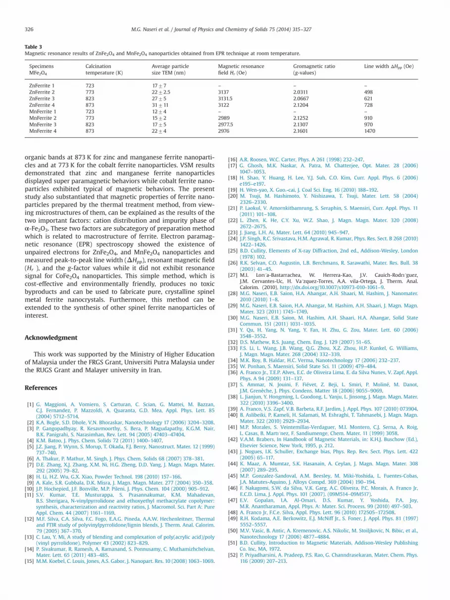
3.5. Magnetic resonance study of metal ferrite nanoparticles
Figs. 11 and 12 show the EPR spectra of ZnFe2O4, and MnFe2O4
nanoparticles calcined at (a) 773 (b) 823, and (c) 873 K exhibitedbroad, symmetrical signals. Peak-to-peak line width (ΔHpp), reso-nant magnetic field (Hr), and g-factor are three parameters thatcharacterize the magnetic properties [61].
It is obvious from Table 3 that the values of ΔHpp and g-factorincrease for ZnFe2O4 and MnFe2O4 nanoparticles when the calci-nation temperature and particle size were increased. In ferrites,variations of ΔHpp and g-factor can be due to dipole–dipoleinteractions and super-exchange interactions [63]. Table 3 alsoshows that the values of the resonant magnetic field decreasedfrom 3137 to 3122 Oe and from 2989 to 2976 Oe for ZnFe2O4, andMnFe2O4 nanoparticles respectively as the calcination temperatureincreased. According to the Eq. (2)
g ¼ hv=βH ð2Þ
where h is Planck's constant, v is the microwave frequency, β is theBohr magnetron (9.274�10�21 erg Oe�1) and H is resonant mag-netic field, the resonance magnetic field should decrease when g-factor increases, whereas v is constant in EPR spectroscopy.
The addition of Fe3þ ions to an A site, as was discussed in thelast part, causes an increase in the super-exchange interactions,contributing to the increase of the internal field and the decreaseof the resonance magnetic field [52]. Cobalt ferrite nanoparticlessynthesized by the thermal treatment method did not exhibitresonance signal. This could be possibly due to the super exchangeinteraction produces that occurs in this nanoparticles. In the someof literatures, authors, [62,63], synthesized CoxZn1�xFe2O4 andreported that in x¼1 (CoFe2O4) there is not any values forΔHpp, Hr
and g. Strong dipole interactions give a large ΔHpp and g valuewhile strong super exchange interaction produces small value ofΔHpp and g value [62,64].
4. Conclusion
The results of this investigation indicate that the thermaltreatment method can be used for synthesizing ZnFe2O4, MnFe2O4
and CoFe2O4 nanoparticles using poly(vinyl pyrrolidon) as acapping agent to stabilize the particles and prevent them fromagglomerating. TG and DTG results exhibited only one mass losswhich started at 678 K and its maximum rate decompositiontemperature was located at 778 K. XRD patterns and TEM imagesshow the formation of MFe2O4 nanoparticles with particle sizes of17–31 nm, 12–22 nm and 14–34 nm for ZnFe2O4, MnFe2O4 andCoFe2O4 nanoparticles respectively. FT-IR confirmed the presenceof metal oxide bands at all temperatures and the absence of
Fig. 11. EPR spectra of zinc ferrite nanoparticles calcined from 773 to 873 K.Fig. 12. EPR spectra of manganese ferrite nanoparticles calcined from 773 to 873 K.
Table 2Magnetic properties of some spinel ferrite nanoparticles reported in the literatures which were measured at room temperature in range of approximately �10 to þ10 kOe.
Specimens Preparation method Average particlesize (nm)
Saturation magnetizationMs (emu/g)
Coercivity field Hc (Oe) References
ZnFerrite Combustion 20 4 Negligible [57]ZnFerrite Modified sol gel �20 1.4 156 [21]NiFerrite Sol gel �9 32.1 59 [58]NiFerrite Coprecipitation 9 11.9 Negligible [59]CoFerrite Mechanic alloying 30 77 2000–2700 [60]CoFerrite Hydrothermal 30 30 Negligible [61]
M.G. Naseri et al. / Journal of Physics and Chemistry of Solids 75 (2014) 315–327 325
organic bands at 873 K for zinc and manganese ferrite nanoparti-cles and at 773 K for the cobalt ferrite nanoparticles. VSM resultsdemonstrated that zinc and manganese ferrite nanoparticlesdisplayed super paramagnetic behaviors while cobalt ferrite nano-particles exhibited typical of magnetic behaviors. The presentstudy also substantiated that magnetic properties of ferrite nano-particles prepared by the thermal treatment method, from view-ing microstructures of them, can be explained as the results of thetwo important factors: cation distribution and impurity phase ofα-Fe2O3. These two factors are subcategory of preparation methodwhich is related to macrostructure of ferrite. Electron paramag-netic resonance (EPR) spectroscopy showed the existence ofunpaired electrons for ZnFe2O4, and MnFe2O4 nanoparticles andmeasured peak-to-peak line width (ΔHpp), resonant magnetic field(Hr ), and the g-factor values while it did not exhibit resonancesignal for CoFe2O4 nanoparticles. This simple method, which iscost-effective and environmentally friendly, produces no toxicbyproducts and can be used to fabricate pure, crystalline spinelmetal ferrite nanocrystals. Furthermore, this method can beextended to the synthesis of other spinel ferrite nanoparticles ofinterest.
Acknowledgment
This work was supported by the Ministry of Higher Educationof Malaysia under the FRGS Grant, Universiti Putra Malaysia underthe RUGS Grant and Malayer university in Iran.
References
[1] G. Maggioni, A. Vomiero, S. Carturan, C. Scian, G. Mattei, M. Bazzan,C.J. Fernandez, P. Mazzoldi, A. Quaranta, G.D. Mea, Appl. Phys. Lett. 85(2004) 5712–5714.
[2] K.A. Bogle, S.D. Dhole, V.N. Bhoraskar, Nanotechnology 17 (2006) 3204–3208.[3] P. Gangopadhyay, R. Kesavmoorthy, S. Bera, P. Magudapathy, K.G.M. Nair,
B.K. Panigrahi, S. Narasimhan, Rev. Lett. 94 (2005) 47403–47404.[4] K.M. Batoo, J. Phys. Chem. Solids 72 (2011) 1400–1407.[5] J.Z. Jiang, P. Wynn, S. Morup, T. Okada, F.J. Berry, Nanostruct. Mater. 12 (1999)
737–740.[6] A. Thakur, P. Mathur, M. Singh, J. Phys. Chem. Solids 68 (2007) 378–381.[7] D.E. Zhang, X.J. Zhang, X.M. Ni, H.G. Zheng, D.D. Yang, J. Magn. Magn. Mater.
292 (2005) 79–82.[8] H. Li, H.Z. Wu, G.X. Xiao, Powder Technol. 198 (2010) 157–166.[9] A. Kale, S.R. Gubbala, D.K. Misra, J. Magn. Magn. Mater. 277 (2004) 350–358.[10] J.P. Hochepied, J.F. Bonville, M.P. Pileni, J. Phys. Chem. 104 (2000) 905–912.[11] S.V. Kumar, T.E. Musturappa, S. Prasannakumar, K.M. Mahadevan,
B.S. Sherigara, N-vinylpyrrolidone and ethoxyethyl methacrylate copolymer:synthesis, characterization and reactivity ratios, J. Macromol. Sci. Part A: PureAppl. Chem. 44 (2007) 1161–1169.
[12] M.F. Silva, C.A. Silva, F.C. Fogo, E.A.G. Pineda, A.A.W. Hechenleitner, Thermaland FTIR study of polyvinylpyrrolidone/lignin blends, J. Therm. Anal. Calorim.79 (2005) 367–370.
[13] C. Lau, Y. Mi, A study of blending and complexation of poly(acrylic acid)/poly(vinyl pyrrolidone), Polymer 43 (2002) 823–829.
[14] P. Sivakumar, R. Ramesh, A. Ramanand, S. Ponnusamy, C. Muthamizhchelvan,Mater. Lett. 65 (2011) 483–485.
[15] M.M. Koebel, C. Louis, Jones, A.S. Gabor, J. Nanopart. Res. 10 (2008) 1063–1069.
[16] A.R. Roosen, W.C. Carter, Phys. A 261 (1998) 232–247.[17] G. Ghosh, M.K. Naskar, A. Patra, M. Chatterjee, Opt. Mater. 28 (2006)
1047–1053.[18] H. Shao, Y. Huang, H. Lee, Y.J. Suh, C.O. Kim, Curr. Appl. Phys. 6 (2006)
e195–e197.[19] H. Wen-yao, X. Guo.-cai, J. Coal Sci. Eng. 16 (2010) 188–192.[20] M. Tsuji, M. Hashimoto, Y. Nishizawa, T. Tsuji, Mater. Lett. 58 (2004)
2326–2330.[21] P. Laokul, V. Amornkitbamrung, S. Seraphin, S. Maensiri, Curr. Appl. Phys. 11
(2011) 101–108.[22] L. Zhen, K. He, C.Y. Xu, W.Z. Shao, J. Magn. Magn. Mater. 320 (2008)
2672–2675.[23] J. Jiang, L.H. Ai, Mater. Lett. 64 (2010) 945–947.[24] J.P. Singh, R.C. Srivastava, H.M. Agrawal, R. Kumar, Phys. Res. Sect. B 268 (2010)
1422–1426.[25] B.D. Cullity, Elements of X-ray Diffraction, 2nd ed., Addison-Wesley, London
(1978) 102.[26] R.K. Selvan, C.O. Augustin, L.B. Berchmans, R. Sarawathi, Mater. Res. Bull. 38
(2003) 41–45.[27] M.I. Lorı´a-Bastarrachea, W. Herrera-Kao, J.V. Cauich-Rodrı´guez,
J.M. Cervantes-Uc, H. Va´zquez-Torres, A.A. vila-Ortega, J. Therm. Anal.Calorim. (2010), http://dx.doi.org/10.1007/s10973-010-1061–9.
[28] M.G. Naseri, E.B. Saion, H.A. Ahangar, A.H. Shaari, M. Hashim, J. Nanomater.2010 (2010) 1–8.
[29] M.G. Naseri, E.B. Saion, H.A. Ahangar, M. Hashim, A.H. Shaari, J. Magn. Magn.Mater. 323 (2011) 1745–1749.
[30] M.G. Naseri, E.B. Saion, M. Hashim, A.H. Shaari, H.A. Ahangar, Solid StateCommun. 151 (2011) 1031–1035.
[31] Y. Qu, H. Yang, N. Yang, Y. Fan, H. Zhu, G. Zou, Mater. Lett. 60 (2006)3548–3552.
[32] D.S. Mathew, R.S. Juang, Chem. Eng. J. 129 (2007) 51–65.[33] F.S. Li, L. Wang, J.B. Wang, Q.G. Zhou, X.Z. Zhou, H.P. Kunkel, G. Williams,
J. Magn. Magn. Mater. 268 (2004) 332–339.[34] M.K. Roy, B. Haldar, H.C. Verma, Nanotechnology 17 (2006) 232–237.[35] W. Ponhan, S. Maensiri, Solid State Sci. 11 (2009) 479–484.[36] A. Franco Jr., T.E.P. Alves, E.C. de Oliveira Lima, E. da Silva Nunes, V. Zapf, Appl.
Phys. A 94 (2009) 131–137.[37] S. Ammar, N. Jouini, F. Fiévet, Z. Beji, L. Smiri, P. Moliné, M. Danot,
J.M. Grenèche, J. Phys. Condens. Matter 18 (2006) 9055–9069.[38] L. Jianjun, Y. Hongming, L. Guodong, L. Yanju, L. Jinsong, J. Magn. Magn. Mater.
322 (2010) 3396–3400.[39] A. Franco, V.S. Zapf, V.B. Barbeta, R.F. Jardim, J. Appl. Phys. 107 (2010) 073904.[40] B. Aslibeiki, P. Kameli, H. Salamati, M. Eshraghi, T. Tahmasebi, J. Magn. Magn.
Mater. 322 (2010) 2929–2934.[41] M.P. Morales, S. Veintemillas-Verdaguer, M.I. Montero, C.J. Serna, A. Roig,
L. Casas, B. Martı´nez, F. Sandiumenge, Chem. Mater. 11 (1999) 3058.[42] V.A.M. Brabers, In Handbook of Magnetic Materials, in: K.H.J. Buschow (Ed.),
Elsevier Science, New York, 1995, p. 212.[43] J. Nogues, I.K. Schuller, Exchange bias, Phys. Rep. Rev. Sect. Phys. Lett. 422
(2005) 65–117.[44] K. Maaz, A. Mumtaz, S.K. Hasanain, A. Ceylan, J. Magn. Magn. Mater. 308
(2007) 289–295.[45] M.P. Gonzalez-Sandoval, A.M. Beesley, M. Miki-Yoshida, L. Fuentes-Cobas,
J.A. Matutes-Aquino, J. Alloys Compd. 369 (2004) 190–194.[46] F. Nakagomi, S.W. da Silva, V.K. Garg, A.C. Oliveira, P.C. Morais, A. Franco Jr,
E.C.D. Lima, J. Appl. Phys. 101 (2007). (09M514–09M517).[47] E.V. Gopalan, I.A. Al-Omari, D.S. Kumar, Y. Yoshida, P.A. Joy,
M.R. Anantharaman, Appl. Phys. A: Mater. Sci. Process. 99 (2010) 497–503.[48] A. Franco Jr, F.C.e. Silva, Appl. Phys. Lett. 96 (2010) 172505–172508.[49] R.H. Kodama, A.E. Berkowitz, E.J. McNiff Jr., S. Foner, J. Appl. Phys. 81 (1997)
5552–5557.[50] M.V. Vasic, B. Antic, A. Kremenovic, A.S. Nikolic, M. Stoiljkovic, N. Bibic, et al.,
Nanotechnology 17 (2006) 4877–4884.[51] B.D. Cullity, Introduction to Magnetic Materials, Addison-Wesley Publishing
Co. Inc, MA, 1972.[52] P. Priyadharsini, A. Pradeep, P.S. Rao, G. Channdrasekaran, Mater. Chem. Phys.
116 (2009) 207–213.
Table 3Magnetic resonance results of ZnFe2O4 and MnFe2O4 nanoparticles obtained from EPR technique at room temperature.
SpecimensMFe2O4
Calcinationtemperature (K)
Average particlesize TEM (nm)
Magnetic resonancefield Hr (Oe)
Gromagnetic ratio(g-values)
Line width ΔHpp (Oe)
ZnFerrite 1 723 1777 – – –
ZnFerrite 2 773 2272.5 3137 2.0311 498ZnFerrite 3 823 2775 3131.5 2.0667 621ZnFerrite 4 873 31711 3122 2.1204 728MnFerrite 1 723 1274 – – –
MnFerrite 2 773 1572 2989 2.1252 910MnFerrite 3 823 1775 2977.5 2.1307 970MnFerrite 4 873 2274 2976 2.1601 1470
M.G. Naseri et al. / Journal of Physics and Chemistry of Solids 75 (2014) 315–327326

[53] B. Antic, N. Jovic, M.B. Pavlovic, A. Kremenovic, D. Manojlović, et al., J. Appl.Phys. 107 (2010) 1–7. (043525).
[54] P. Holec, J. Plocek, D. Niznansky, J. Poltierova´ Vejpravova, J Sol–Gel Sci.Technol. 51 (2009) 301–305.
[55] Sangmanee, Maensiri, Appl. Phys. A 97 (2009) 167–177.[57] M. George, A.M. John, S.S. Nair, P.A. Joy, M.R. Anantharaman, J. Magn. Magn.
Mater. 302 (2006) 190–195.[58] V. Sepelak, M. Menzel, I. Bergmann, M. Wiebcke, F. Krumeich, K.D. Becker,
J. Magn. Magn. Mater. 272-276 (2004) 1616–1618.
[59] D. Zhao, X. Wu, H. Guan, E. Han, J. Supercrit. Fluids 42 (2007) 226–233.[60] H. Chaoquan, G. Zhenghong, Y. Xiaorui, J. Magn. Magn. Mater. 320 (2008) L70–L73.[61] S.N. Sidorov, L.M. Bronstein, V.A. Davankov, M.P. Tsyurupa, S.P. Solodovnikov,
P.M. Valetsky, E.A. Wilder, R.J. Spontak, Chem. Mater. 11 (1999) 3210–3215.[62] G. Vaidyanathana, S. Sendhilnathan, Phys. B 403 (2008) 2157–2167.[63] L. Li, G. Li, R.L. Smith, H. Inomata, Chem. Mater. 12 (2000) 3705–3714.[64] M.G. Naseri, E.B. Saion, H.A. Ahangar, A.H. Shaari, Mater. Res. Bull. 48 (2013)
1439–1446.
M.G. Naseri et al. / Journal of Physics and Chemistry of Solids 75 (2014) 315–327 327