3d digital terrestrial model creation using image assisted total station and rapid prototyping...
TRANSCRIPT
3D Digital Terrestrial ModelCreation Using ImageAssisted Total Station andRapid Prototyping TechnologybyG. Pantazis, E. Lambrou, S. Polydoras and V. Gotsis
Reprinted from
International Journal ofHeritage in the Digital Eravolume 2 number 2 2013
245
3D Digital Terrestrial ModelCreation Using ImageAssisted Total Station andRapid PrototypingTechnologyG. Pantazis, E. Lambrou, S. Polydoras and V. Gotsis
volume 2 number 2 2013International Journal of Heritage in the Digital Era
246
3D Digital Terrestrial Model CreationUsing Image Assisted Total Station andRapid Prototyping TechnologyG. Pantazis, E. Lambrou, S. Polydoras and V. Gotsis
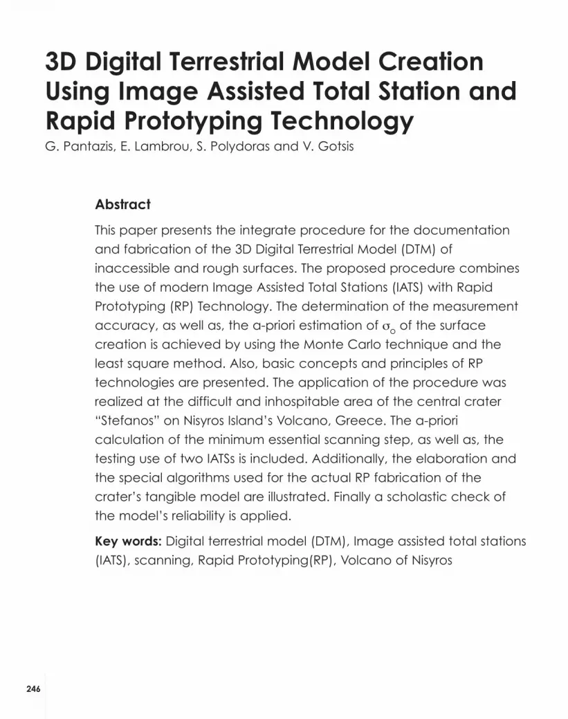
Abstract
This paper presents the integrate procedure for the documentation
and fabrication of the 3D Digital Terrestrial Model (DTM) of
inaccessible and rough surfaces. The proposed procedure combines
the use of modern Image Assisted Total Stations (IATS) with Rapid
Prototyping (RP) Technology. The determination of the measurement
accuracy, as well as, the a-priori estimation of σo of the surface
creation is achieved by using the Monte Carlo technique and the
least square method. Also, basic concepts and principles of RP
technologies are presented. The application of the procedure was
realized at the difficult and inhospitable area of the central crater
“Stefanos” on Nisyros Island’s Volcano, Greece. The a-priori
calculation of the minimum essential scanning step, as well as, the
testing use of two IATSs is included. Additionally, the elaboration and
the special algorithms used for the actual RP fabrication of the
crater’s tangible model are illustrated. Finally a scholastic check of
the model’s reliability is applied.
Key words: Digital terrestrial model (DTM), Image assisted total stations
(IATS), scanning, Rapid Prototyping(RP), Volcano of Nisyros

1. Introduction
Today the evolution of technology in surveying presents the new bornImage Assisted Total Station (IATS). These instruments firstly enable the socalled intelligent tacheometry (Scherer and Lerma 2009). IATSs arealready used in specific applications such as remote monitoringmethods instead of laser scanners or terrestrial aperture radar. The mainreason is that they enable high accuracy (down to mm range) in allthree coordinates directions even without targeting (Reiterer et al 2008).
On the other hand emerging from the field of MechanicalEngineering, a range of innovative, highly automated technologies(SLA, SLS, FDM, LOM, 3DP), have been introduced and evolved duringthe last two decades, recognized and described under the genericterm Rapid Prototyping (RP) Technologies, also referred to as AdditiveManufacturing, Freeform Fabrication, Layered Manufacturing, or evensimply 3D Printing (Pham and Dimov 2001; Li Yan et al 2009). They utilizedigital 3D geometrical data (originating from several different sources,such as CAD systems, 3D Scanners, Coordinate Measuring Machines,CT and MR tomography) for the additive fabrication of physicalobjects in successive layers. Prior to RP fabrication, the 3D data areproperly prepared in computer software environments as 3D Solid CADModels and then transferred to RP Machines via specific computer fileformats (e.g. STL, VRML), (Kumar 1997; Fischer et al 2005), that fullydescribe the solid’s boundary surface as an ordered triangulatedmesh and assist for the appropriate for RP algorithmic layerpreparation (slicing procedure).
The presented work aims to a total survey and digitaldocumentation and representation of inaccessible and roughsurfaces. Furthermore, the ability to fabricate actual tangible RapidPrototyping models for them, based on the actual measured data,after appropriate processing via dedicated software has beeninvestigated and is illustrated.
2. Comparison between Image Assisted Total Stations andTerrestrial Laser Scanners
IATSs perform all the common functions as simplified total stations. Alsoare equipped with at least one CCD camera. In some cases theyincorporate two CCD cameras a wide angle (WA) camera attachedat the top of their telescope and an internal camera for capturingdetailed images. Therefore they have extra ability of scanning similarto those of Terrestrial Laser Scanners (TLS). That is why they are oftencalled “light” scanners. IATSs are more convenient and easy to use.These instruments introduce a revolution in geoapplications, as theyeasily provide accurate data and complete models of the scanned
2473D Digital Terrestrial Model Creation Using Image Assisted Total Station andRapid Prototyping Technology
objects, comparable to the ones obtained by TLS. For this reason theuse of IATSs in some applications seems to be advantageous againstthe TLS.
TLSs are widely used for 3D modeling of buildings, constructions etc.Most of them are very expensive and difficult to carry out to the field,due to their increased total weight (including batteries) and also to theneed for a computer at the site. Additionally TLSs measure a mass ofdense points for every second of use (reaches 1million points/sec)instead of the IATSs, which measure a single point for each observation(Hai H. 2008). So the collected by TLSs data files are enormous. Thelighter TLS models, which are more accurately and convenient (FAROFocus3D, 2013) limit the range of their measurements to some meter’sdecades (10m-40m). This is prohibitive for many applications.
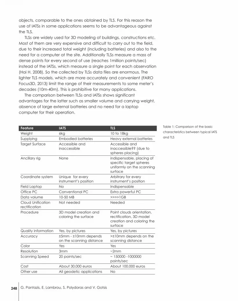
The comparison between TLSs and IATSs shows significantadvantages for the latter such as smaller volume and carrying weight,absence of large external batteries and no need for a laptopcomputer for their operation.
Table 1: Comparison of the basic
characteristics between typical IATS
and TLS
248 G. Pantazis, E. Lambrou, S. Polydoras and V. Gotsis
Feature IATS TLSWeight 6kg 10 to 18kg
Supplying Embodied batteries Heavy external batteries
Target Surface Accessible and Accessible and inaccessible inaccessible?? (due to
spheres placing)
Ancillary rig None indispensable, placing ofspecific target spheresuniformly on the scanningsurface
Coordinate system Unique for every Arbitrary for every instrument’s position instrument’s position
Field Laptop No Indispensable
Office PC Conventional PC Extra powerful PC
Data volume 10-50 MB >>>>1GB
Cloud Unification Not needed Neededrectification
Procedure 3D model creation and Point clouds orientation, coloring the surface rectification, 3D model
creation and coloring thesurface
Quality information Yes, by pictures Yes, by pictures
Accuracy ±5mm - ±10mm depends >±10mm depends on the on the scanning distance scanning distance
Color Yes Yes
Resolution 3mm ~2mm
Scanning Speed 20 points/sec ~ 150000 -1000000points/sec
Cost About 30,000 euros About 100.000 euros
Other use All geodetic applications No
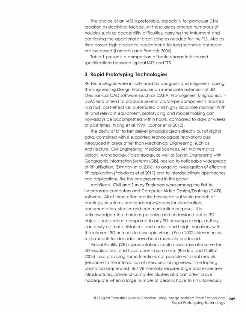
The choice of an IATS is preferable, especially for particular DTMcreation as declivities façade. At these areas emerge numerous oftroubles such as accessibility difficulties, carrying the instrument andpositioning the appropriate target spheres needed for the TLS. Also astime passes high accuracy requirements for long scanning distancesare increased (Lambrou and Pantazis 2006).
Table 1 presents a comparison of basic characteristics andspecifications between typical IATS and TLS.
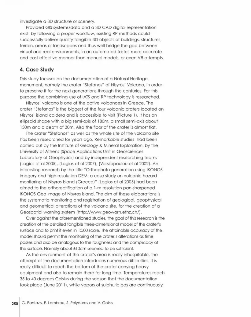
3. Rapid Prototyping Technologies
RP Technologies were initially used by designers and engineers, duringthe Engineering Design Process, as an immediate extension of 3DMechanical CAD software (such as CATIA, Pro-Engineer, Unigraphics, I-DEAS and others) to produce several prototype components required,in a fast, cost-effective, automated and highly accurate manner. WithRP and relevant equipment, prototyping and model making cannowadays be accomplished within hours, compared to days or weeksof past times (Wang et al 1999; Jauhar et al 2012).
The ability of RP to fast deliver physical objects directly out of digitaldata, combined with IT supported technological innovations alsointroduced in areas other than Mechanical Engineering, such asArchitecture, Civil Engineering, Medical Sciences, Art, Mathematics,Biology, Archaeology, Paleontology, as well as Survey Engineering withGeographic Information Systems (GIS), has led to noticeable widespreadof RP utilization, (Dimitrov et al 2006), to ongoing investigation of effectiveRP application (Polydoras et al 2011) and to interdisciplinary approachesand applications, like the one presented in this paper.
Architects, Civil and Survey Engineers were among the first toincorporate computers and Computer Aided Design/Drafting (CAD)software. All of them often require having actual scale models ofbuildings, structures and landscapes/areas for visualization,documentation, studies and communication purposes. It isacknowledged that humans perceive and understand better 3Dobjects and scenes, compared to any 2D drawing or map, as theycan easily estimate distances and understand height variations withthe inherent 3D human stereoscopic vision, (Rase 2002). Nevertheless,such models for decades have been manually produced.
Virtual Reality (VR) representations could nowadays also serve for3D visualizations, and have been in some use, (Burdea and Coiffet2003), also providing some functions not possible with real models(response to the interaction of users, sectioning views, time lapsing,animation sequences). But VR normally requires large and expensiveinfrastructures, powerful computer clusters and can often proveinadequate when a large number of persons have to simultaneously
2493D Digital Terrestrial Model Creation Using Image Assisted Total Station andRapid Prototyping Technology
investigate a 3D structure or scenery.Provided GIS systems/data and a 3D CAD digital representation
exist, by following a proper workflow, existing RP methods couldsuccessfully deliver quality tangible 3D objects of buildings, structures,terrain, areas or landscapes and thus well bridge the gap betweenvirtual and real environments, in an automated faster, more accurateand cost-effective manner than manual models, or even VR attempts.
4. Case Study
This study focuses on the documentation of a Natural Heritagemonument, namely the crater “Stefanos” of Nisyros’ Volcano, in orderto preserve it for the next generations through the centuries. For thispurpose the combining use of IATS and RP technology is researched.
Nisyros’ volcano is one of the active volcanoes in Greece. Thecrater “Stefanos” is the biggest of the four volcanic craters located onNisyros’ island caldera and is accessible to visit (Picture 1). It has anellipsoid shape with a big semi-axis of 180m, a small semi-axis about130m and a depth of 30m. Also the floor of the crater is almost flat.
The crater “Stefanos” as well as the whole site of the volcano sitehas been researched for years ago. Remarkable studies had beencarried out by the Institute of Geology & Mineral Exploration, by theUniversity of Athens (Space Applications Unit in Geosciences,Laboratory of Geophysics) and by independent researching teams(Lagios et al 2005), (Lagios et al 2007), (Vassilopoulou et al 2002). Aninteresting research by the title “Orthophoto generation using IKONOSimagery and high-resolution DEM: a case study on volcanic hazardmonitoring of Nisyros Island (Greece)” (Lagios et al 2005) had beenaimed to the orthorectification of a 1-m resolution pan-sharpenedIKONOS Geo image of Nisyros island. The aim of these elaborations isthe systematic monitoring and registration of geological, geophysicaland geometrical alterations of the volcano site, for the creation of aGeospatial warning system (http://www.geowarn.ethz.ch/).
Over against the aforementioned studies, the goal of this research is thecreation of the detailed tangible three-dimensional model of the crater’ssurface and to print it even in 1:500 scale. The attainable accuracy of themodel should permit the monitoring of the crater’s alterations as timepasses and also be analogous to the roughness and the complicacy ofthe surface. Namely about ±10cm seemed to be sufficient.
As the environment at the crater’s area is really inhospitable, theattempt of the documentation introduces numerous difficulties. It isreally difficult to reach the bottom of the crater carrying heavyequipment and also to remain there for long time. Temperatures reach35 to 40 degrees Celsius during the season that the documentationtook place (June 2011), while vapors of sulphuric gas are continuously
250 G. Pantazis, E. Lambrou, S. Polydoras and V. Gotsis

gushed out from the earth’s hurt, making the stay nearly insufferable.Thus the use of IATS seemed to be the best solution for this task. Thearea of the declivity to be scanned was about 25000 square meters,while the crater’s floor surface is about 50000 square meters.
4.1 A-priori Scanning Analysis
It has been proved that the a-priori estimation of the minimumessential scanning step, when using an IATS is feasible by using aspecial statistical technique (Pantazis and Nikolitsas 2011).
The Monte Carlo technique is used combining with the least squaremethod (Rubinstein 1981;JCGM 101:2008 2008), for calculating boththe uncertainty of the coordinates of the measured points and thestandard error of the adaptation of a surface to these points.
Utilizing as input data the measurement uncertainty of angles anddistances provided by the IATS and the scanning distance, about10000 simulations of the coordinates’(x, y, z) calculation are carriedout leading to the reliable estimation of σx, σy, σz (Alkhatib et al 2009).
Then, providing the coordinates’ uncertainty and the scanning distanceas input data, the standard error of the adaptation of a concretegeometrical surface to the measured points can be determined.
Consequently by using the above calculated standard error theminimum essential scanning step (s) for confidence level 95% can becalculated by the equation
s = s0 · z95% (1)
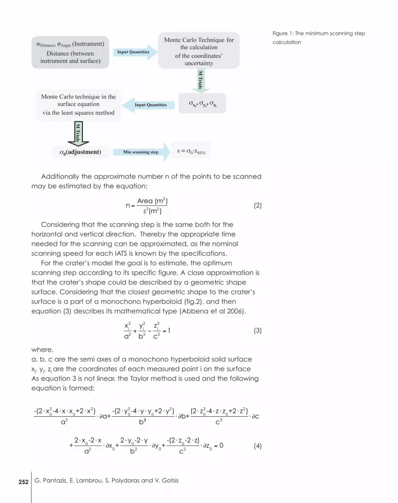
Figure 1 presents the aforementioned procedure. It’s obvious that asmaller scanning step has no reason, as it would lie close to theprocedure’s uncertainty namely under the threshold of the adaptationnoise.
Picture 1. The Crater “Stefanos” of
the volcano
2513D Digital Terrestrial Model Creation Using Image Assisted Total Station andRapid Prototyping Technology
Additionally the approximate number n of the points to be scannedmay be estimated by the equation:
(2)
Considering that the scanning step is the same both for thehorizontal and vertical direction. Thereby the appropriate timeneeded for the scanning can be approximated, as the nominalscanning speed for each IATS is known by the specifications.
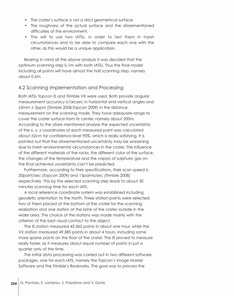
For the crater’s model the goal is to estimate, the optimumscanning step according to its specific figure. A close approximation isthat the crater’s shape could be described by a geometric shapesurface. Considering that the closest geometric shape to the crater’ssurface is a part of a monochono hyperboloid (fig.2), and thenequation (3) describes its mathematical type (Abbena et al 2006).
(3)
where, a, b, c are the semi axes of a monochono hyperboloid solid surface xi, yi, zi are the coordinates of each measured point i on the surfaceAs equation 3 is not linear, the Taylor method is used and the followingequation is formed:
(4)02 0
+2 x -2 x
ax +
2⋅ ⋅⋅ ∂
⋅⋅ ⋅⋅ ∂
⋅ ⋅⋅ ∂ =
y -2 y
by +
-(2 z -2 z)
cz0
2 002 0
0
-(2 x -4 x x +2 x )
aa+
-(2 y -4 y y +2 y )
b02
02
302
02⋅ ⋅ ⋅ ⋅
⋅ ∂⋅ ⋅ ⋅ ⋅
3302
02
3b+
(2 z -4 z z +2 z )
cc+⋅ ∂
⋅ ⋅ ⋅ ⋅⋅ ∂
x
a
y
b
z
c1i
2
2i2
2i2
2+ − =
nArea (m )
s (m )
2
2 2=
252 G. Pantazis, E. Lambrou, S. Polydoras and V. Gotsis
σ0(adjustment)
σxi, σyi
, σzi
s = σ0·z95%
Figure 1: The minimum scanning step
calculation

By applying the least square method via the Monte Carlotechnique on the equation (4), performing about 10000 adjustments,the a-priori σ0 of the adaptation of the surface to the points to bemeasured is calculated for confidence level 95% (fig.3) (Gotsis 2012).According to the diagram as IATSs which will be used provide ±1′′angular accuracy, so σ0 of the points adaptation to this surface isequal to ± 22cm. This defines the minimum essential scanning step thatthe concrete geometrical surface could be scanned. Under thisthreshold a smaller scanning step has no sense as underlie the noise ofadaptation. However nothing better out of this σ0 could be achievedas the crater’s surface is a rather rough surface.
Apart from the above approximation the final decision, for theoptimum scanning step should take into consideration the followingparameters:
Figure 2. The monochono
hyperboloid
2533D Digital Terrestrial Model Creation Using Image Assisted Total Station andRapid Prototyping Technology
b a
c
Figure 3: The a-priori standard error
σo for the points’adaptation to a
monochono hyperboloid, for
confidence level 95%, for different
IATSs accuracy.
• The crater’s surface is not a strict geometrical surface. • The roughness of the actual surface and the aforementioned
difficulties of the environment.• The will to use two IATSs, in order to test them in harsh
circumstances and to be able to compare each one with theother, as this would be a unique application.
Bearing in mind all the above analysis it was decided that theoptimum scanning step is 1m with both IATSs. Thus the final modelincluding all points will have almost the half scanning step, namelyabout 0.5m.
4.2 Scanning Implementation and Processing
Both IATSs Topcon IS and Trimble VX were used. Both provide angularmeasurement accuracy ±1arcsec in horizontal and vertical angles and±5mm ± 2ppm (Trimble 2008,Topcon 2009) in the distancemeasurement on the scanning mode. They have adequate range tocover the crater surface from its center, namely about 200m.According to the afore mentioned analysis the expected uncertaintyof the x, y, z coordinates of each measured point was calculatedabout ±2cm for confidence level 95%, which is really satisfying. It ispointed out that the aforementioned uncertainty may be worseningdue to harsh environmental circumstances in the crater. The influenceof the different materials of the rocks, the different color of the surface,the changes of the temperature and the vapors of sulphuric gas onthe final achieved uncertainty can’t be predicted.
Furthermore, according to their specifications, their scan speed is20point/sec (Topcon 2009) and 15points/sec (Trimble 2008)respectively. This by the selected scanning step leads to about 30minutes scanning time for each IATS.
A local reference coordinate system was established includinggeodetic orientation to the North. Three station-points were selected;two of them placed at the bottom of the crater for the scanningrealization and one station at the brink of the crater outside in thewider area. The choice of the stations was made mainly with thecriterion of the best visual contact to the object.
The IS station measured 45.362 points in about one hour, while theVX station measured 49.585 points in about 4 hours, including somemore sparse points on the floor of the crater. The IS proved to measurereally faster, as it measures about equal number of points in just aquarter only of the time.
The initial data processing was carried out in two different softwarepackages, one for each IATS, namely the Topcon’s Image MasterSoftware and the Trimble’s Realworks. The goal was to process the
254 G. Pantazis, E. Lambrou, S. Polydoras and V. Gotsis
point clouds, create the surface and color it based on realphotographs of the terrain taken during the scanning.
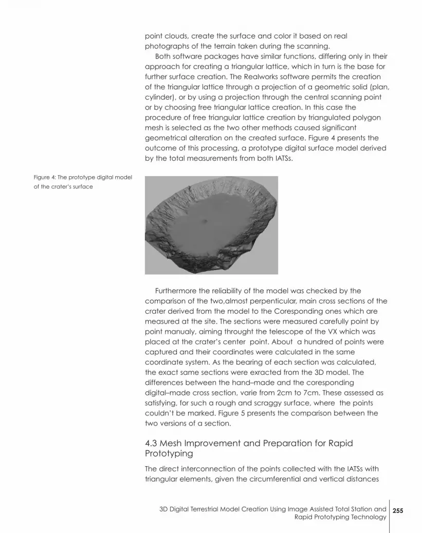
Both software packages have similar functions, differing only in theirapproach for creating a triangular lattice, which in turn is the base forfurther surface creation. The Realworks software permits the creationof the triangular lattice through a projection of a geometric solid (plan,cylinder), or by using a projection through the central scanning pointor by choosing free triangular lattice creation. In this case theprocedure of free triangular lattice creation by triangulated polygonmesh is selected as the two other methods caused significantgeometrical alteration on the created surface. Figure 4 presents theoutcome of this processing, a prototype digital surface model derivedby the total measurements from both IATSs.
Furthermore the reliability of the model was checked by thecomparison of the two,almost perpenticular, main cross sections of thecrater derived from the model to the Coresponding ones which aremeasured at the site. The sections were measured carefully point bypoint manualy, aiming throught the telescope of the VX which wasplaced at the crater’s center point. About a hundred of points werecaptured and their coordinates were calculated in the samecoordinate system. As the bearing of each section was calculated,the exact same sections were exracted from the 3D model. Thedifferences between the hand–made and the corespondingdigital–made cross section, varie from 2cm to 7cm. These assessed assatisfying, for such a rough and scraggy surface, where the pointscouldn’t be marked. Figure 5 presents the comparison between thetwo versions of a section.
4.3 Mesh Improvement and Preparation for RapidPrototyping
The direct interconnection of the points collected with the IATSs withtriangular elements, given the circumferential and vertical distances
Figure 4: The prototype digital model
of the crater’s surface
2553D Digital Terrestrial Model Creation Using Image Assisted Total Station andRapid Prototyping Technology

selected for scanning, resulted in a relatively un-natural aesthetic resultfor the crater’s surface, resembling to a terraced surface.
To further enhance the natural look of the crater’s scan, before theactual RP construction of a model, it was - at this point - decided toincorporate some software tools mostly used in Reverse Engineering(RE) - Mechanical Engineering (ME) applications in relevant dedicatedRE & ME software, namely Geomagic Studio. Algorithmic “spikeremoval” to eliminate sharp points and “surface smoothing”commands were used on the triangular mesh of the crater, to such anextent that its surface would not much deviate from the actual pointscollected and would still look macroscopically realistic, but noticeablysmoother.
The result of the surfaces before and after their improvement canbe seen in Figure 6.
Figure 5: The comparison between
the two two versions of a section.
256 G. Pantazis, E. Lambrou, S. Polydoras and V. Gotsis
Figure 6: STL files prepared for Rapid Prototyping

A segment of the crater in both forms, of processed andunprocessed terrain surface, was decided to be RP reproduced forsurface enhancement evaluation, before building a full crater model.
As stated above, RP requires a solid part, or else a closed-surfacevolume, to build an object. Up to this point, only triangulated meshesof an open surface of the crater were available. In order to end upwith solid parts, another RP dedicated/STL manipulation software tool,Magics RP, was used. All surface models of the crater (the raw andenhanced segments, as well as the full one) were imported in thissoftware and their upper – outer boundary was vertically extruded (Z-axis), at a distance below the craters lowest height, thus forming asolid. Further, by “cutting off” the digital models via a XY orientedplane, full solid models of the crater were achieved, resembling muchlike an athletic stadium. Proper triangle reduction in areas ofredundant meshing, to later reduce processing times on the RPmachine, was also performed before exporting the final solids of thecrater into STL files for Rapid Prototyping.
For the actual fabrication of tangible RP models of the Nisyros’crater, a Helisys Laminated Object Manufacturing, model LOM1015Rapid Prototyping Machine was used, hosted in the Rapid Prototypingand Tooling Laboratory of the School of Mechanical Engineering ofNTUA. This LOM1015 machine utilizes 0.1mm thick sheet of paper inorder to additively build parts, in layers processed with a CO2 laser,with an achieved dimensional accuracy of approximately ±0.25mm.
Parts produced by a LOM machine look much like wooden objects,in a natural brownish shade, well suitable for the presentedapplication.
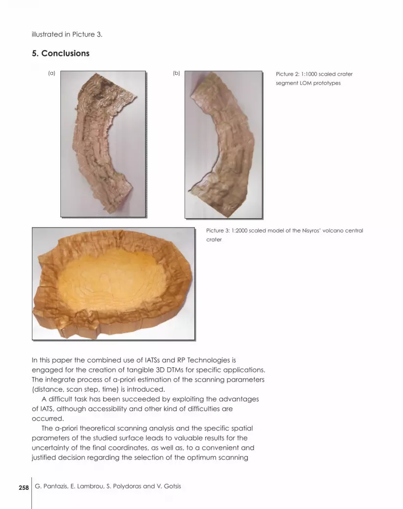
In a first prototyping stage the two variations of a segment of thecrater were built, scaled 1:1000, in order to aesthetically evaluate theresult, prior to the full crater fabrication. A “raw” version with theterrain’s surface exactly as exported by the Topcon’s Image Mastersoftware (Picture 2a) and the same segment with the surfaceenhancements performed in the Geomagic Studio environment(Picture 2b). The two parts were simultaneously built in the LOMmachine in about 14.5 hours, requiring another 2 hours for partseparation and minor post-processing. By examining the objectsobtained, it was verified that the software-enhanced crater surface-planned for full prototyping- indeed, looked more natural and realistic(Picture 2b).
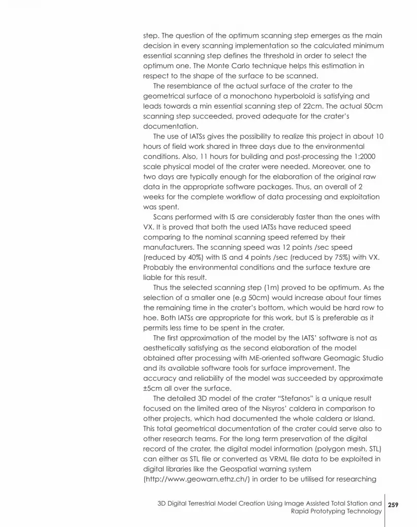
Therefore, in a second prototyping stage, the STL file of theenhanced version of the Nisyros’ crater, scaled 1:2000 in respect to theactual, was also transferred to the LOM machine for fabrication.
In about 8 hours of actual build time and another 3 hours for partseparation, part surface protection and finishing, a complete 1:2000tangible scale model of the Nisyros crater was completed. It is
2573D Digital Terrestrial Model Creation Using Image Assisted Total Station andRapid Prototyping Technology
illustrated in Picture 3.
5. Conclusions
In this paper the combined use of IATSs and RP Technologies isengaged for the creation of tangible 3D DTMs for specific applications.The integrate process of a-priori estimation of the scanning parameters(distance, scan step, time) is introduced.
A difficult task has been succeeded by exploiting the advantagesof IATS, although accessibility and other kind of difficulties areoccurred.
The a-priori theoretical scanning analysis and the specific spatialparameters of the studied surface leads to valuable results for theuncertainty of the final coordinates, as well as, to a convenient andjustified decision regarding the selection of the optimum scanning
Picture 2: 1:1000 scaled crater
segment LOM prototypes
258 G. Pantazis, E. Lambrou, S. Polydoras and V. Gotsis
(a) (b)
Picture 3: 1:2000 scaled model of the Nisyros’ volcano central
crater
step. The question of the optimum scanning step emerges as the maindecision in every scanning implementation so the calculated minimumessential scanning step defines the threshold in order to select theoptimum one. The Monte Carlo technique helps this estimation inrespect to the shape of the surface to be scanned.
The resemblance of the actual surface of the crater to thegeometrical surface of a monochono hyperboloid is satisfying andleads towards a min essential scanning step of 22cm. The actual 50cmscanning step succeeded, proved adequate for the crater’sdocumentation.
The use of IATSs gives the possibility to realize this project in about 10hours of field work shared in three days due to the environmentalconditions. Also, 11 hours for building and post-processing the 1:2000scale physical model of the crater were needed. Moreover, one totwo days are typically enough for the elaboration of the original rawdata in the appropriate software packages. Thus, an overall of 2weeks for the complete workflow of data processing and exploitationwas spent.
Scans performed with IS are considerably faster than the ones withVX. It is proved that both the used IATSs have reduced speedcomparing to the nominal scanning speed referred by theirmanufacturers. The scanning speed was 12 points /sec speed(reduced by 40%) with IS and 4 points /sec (reduced by 75%) with VX.Probably the environmental conditions and the surface texture areliable for this result.
Thus the selected scanning step (1m) proved to be optimum. As theselection of a smaller one (e.g 50cm) would increase about four timesthe remaining time in the crater’s bottom, which would be hard row tohoe. Both IATSs are appropriate for this work, but IS is preferable as itpermits less time to be spent in the crater.
The first approximation of the model by the IATS’ software is not asaesthetically satisfying as the second elaboration of the modelobtained after processing with ME-oriented software Geomagic Studioand its available software tools for surface improvement. Theaccuracy and reliability of the model was succeeded by approximate±5cm all over the surface.
The detailed 3D model of the crater “Stefanos” is a unique resultfocused on the limited area of the Nisyros’ caldera in comparison toother projects, which had documented the whole caldera or Island.This total geometrical documentation of the crater could serve also toother research teams. For the long term preservation of the digitalrecord of the crater, the digital model information (polygon mesh, STL)can either as STL file or converted as VRML file data to be exploited indigital libraries like the Geospatial warning system(http://www.geowarn.ethz.ch/) in order to be utilised for researching
2593D Digital Terrestrial Model Creation Using Image Assisted Total Station andRapid Prototyping Technology
and tourist reasons as well. Apart from that, the real object (RP prototype), which is
documenting the current image of the crater could be used as amaster pattern for reproduction of replicas.
More over the replication of the survey after some years will lead toreliable results for the crater’s monitoring such as in similar researches(Pesci A. et al 2013).
The LOM RP technology utilized, successfully delivers a realistictangible model of the crater, while the Geomagic Studio routinespermit a natural smoothing of the surface that enhances theresemblance to the actual crater’s terrain.
The LOM RP model of the full crater presented a very realistic resultand close resemblance to the actual volcano, as can be justified byphotographs and satellite images of the area.
Conclusively IATSs may deservingly be used instead of TLSs savingmoney and labour in specific detailed DTMs creation. Additionally it isproved that the combined use of 3D spatial data and RP technology,it can find interesting application in natural structures documentationand not just for the creation of mechanical products, in which hadbeen utilized till today.
ReferencesAbbena E., Gray, A., Salamon S., 2006. Modern Differential Geometry of Curvesand Surfaces with Mathematica, Third Edition (Studies in AdvancedMathematics)
Alkhatib, H., Neumann, I., Kutterer, H., 2009. Uncertainty modeling of randomand systematic errors by means of Monte Carlo and fuzzy techniques. Journalof Applied Geodesy. Volume 3, Issue 2, Pages 67–79, DOI: 10.1515/JAG.2009.008
Burdea, G. C., Coiffet, P., 2003. Virtual Reality Technology, 2nd ed. Wiley-Interscience
Dimitrov D., Schreve K., de Beer N., 2006. Advances in three dimensional printing– state of the art and future perspectives, Rapid Prototyping Journal, Vol. 12 Iss:3, pp.136 – 147
FARO Focus3D, 2013. Features, Benefits & Technical Specifications
Fischer T., Burry M., Frazer J., 2005. Triangulation of generative form forparametric design and rapid prototyping, Automation in Construction, Volume14, Issue 2, Pages 233-240, ISSN 0926-5805,http://dx.doi.org/10.1016/j.autcon.2004.07.004.
Gotsis V., 2012. Modeling of geometric and non-geometric surfaces by usingspatial imaging stations (In Greek), Diploma thesis.
Hai H., 2008. 3D Terrestrial Laser Scanning For Application In Earthwork AndTopographical Surveys, University of Southern Queensland, Faculty ofEngineering and Surveying, Bachelor of Spatial Science (Surveying)
Jauhar S., Asthankar K.M. & Kuthe A.M., 2012. Cost benefit analysis of RapidManufacturing in Automotive Industries, Advances in Mechanical Engineeringand its Applications (AMEA), Vol. 2, No. 3, pp.181-188, ISSN 2167-6380
JCGM 101:2008, 2008. Evaluation of measurement data – Supplement 1 to the
260 G. Pantazis, E. Lambrou, S. Polydoras and V. Gotsis
“Guide to the expression of uncertainty in measurement – Propagation ofdistributions using a Monte Carlo method.
Kumar, V., 1997. An assessment of data formats for layered manufacturing,Advances in Engineering Software 28.3 : 151-164.
Lagios E., Sakkas V., Parcharidis Is.,Dietrich V., 2005. Ground deformation ofNisyros Volcano (Greece) for the period 1995–2002: Results from DInSAR andDGPS observations, Bull Volcanol 68: 201–214, DOI 10.1007/s00445-005-0004-y
Lagios E., Vassilopoulou S., Sakkas V., Dietrich V., Damiata B.N., Ganas A., 2007.Testing satellite and ground thermal imaging of low-temperature fumarolicfields: The dormant Nisyros Volcano (Greece), ISPRS Journal of Photogrammetry& Remote Sensing 62, pp 447–460.
Lambrou E., Pantazis G., 2006. A new geodetic methodology for the accuratedocumentation and monitoring of inaccessible surfaces. Proceedings of “3rd
IAG symposium on Geodesy for Geotechnical and Structural Engineering and12th International FIG symposium on deformation measurements”, Baden,Austria.
Li Yan, Y., Zhang S., R., Wu Lin, F., Lu R., Q., Xiong, Z., et al., 2009. RapidPrototyping and Manufacturing Technology: Principle, Representative Technics,Applications, and Development Trends. Tsinghua Science Technology, 14(June),1–12. doi:10.1016/S1007-0214(09)70059-8
Pantazis G., Nikolitsas K., 2011. Assessing the use of “light” laser scanners and theMonte Carlo technique for the documentation of geometric surfaces, FIGWorking Week 2011, Bridging the Gap between Cultures, Marrakech, Morocco
Pesci A., Teza G., Casula G., Fabris M., Bonforte A., 2013. Remote Sensing andGeodetic Measurements for Volcanic Slope Monitoring: Surface VariationsMeasured at Northern Flank of La Fossa Cone (Vulcano Island, Italy), RemoteSensing, ISSN 2072-4292 2238-2256, doi:10.3390/rs5052238
Pham, D. T., Dimov, S. S., 2001. Rapid Manufacturing: The technologies &applications of Rapid Prototyping and Rapid Tooling, Springer, London, UK
Polydoras S., Sfantsikopoulos M., and Provatidis C., 2011. Rational Embracing ofModern Prototyping Capable Design Technologies into the Tools Pool ofProduct Design Teams, ISRN Mechanical Engineering, vol. 2011, Article ID739892, 12 pages, 2011. doi:10.5402/2011/739892
Rase, W.D. 2002. Physical models of GIS objects by rapid prototyping,geospatial theory, processing and applications, Proceedings of the ISPRSTechnical Commission IV Symposium 2002, The International Archives of thePhotogrammetry, Remote Sensing and Spatial Information Sciences, GITC,available at: www.isprs.org/commission4/proceedings/pdfpapers/237.pdf
Reiterer A., Lehmann M., Miljanovic M. , Ali H., Paar G., Egly U., Eiter T. andKahmen H., 2008. Deformation monitoring using a new kind of optical 3dmeasurement system: components and perspectives. Proceedings of 13th figinternational symposium on deformation measurements and analysis and 4thIAG symposium on geodesy for geotechnical and Structural engineering.Lisboa.
Rubinstein R.Y., 1981. Simulation and the Monte Carlo method. John Wiley &Sons, New York.
Scherer M., and Lerma J. L, 2009. From the Conventional Total Station to theProspective Image Assisted Photogrammetric Scanning Total Station:Comprehensive Review. Journal of Surveying Engineering, Vol. 135, No. 4,November 2009, pp. 173-178, (doi: http://dx.doi.org/10.1061/(ASCE)0733-9453(2009)135:4(173)
Topcon Corporation Tokyo, Japan, 2009. Instruction manual Imaging Station IS.
2613D Digital Terrestrial Model Creation Using Image Assisted Total Station andRapid Prototyping Technology
Trimble Navigation Limited 2008. Sunnyvale, California 94085, 2009. Users manualfor Trimble Vx
Vassilopoulou S., Hurni L., Dietrich V., Baltsavias E., Pateraki M., Lagios E.,Parcharidis Is, 2002. Orthophoto generation using IKONOS imagery and high-resolution DEM: a case study on volcanic hazard monitoring of Nisyros Island(Greece), ISPRS Journal of Photogrammetry & Remote Sensing 57, pp 24– 38
Wang W., Conley J. G., Stoll H. W., 1999. Rapid tooling for sand casting usinglaminated object manufacturing process, Rapid Prototyping Journal, Vol. 5 Iss:3, pp.134 – 141
262 G. Pantazis, E. Lambrou, S. Polydoras and V. Gotsis
G. Pantazisa,*, E. Lambroua, S. Polydorasb and V. Gotsisc
aSchool of Surveying Engineering, National Technical Univ. of Athens,9Polytehniou St., Zografos Campus, Athens, 15780, Greece(gpanta, litsal) @central.ntua.gr
bRapid Prototyping & Tooling Laboratory, School of MechanicalEngineering, National Technical Univ. of Athens, 9 Polytehniou St.,Zografos Campus, Athens, 15780, [email protected]