model-driven rapid prototyping with umple
TRANSCRIPT
For Review 1
Model-Driven Rapid Prototyping with Umple
Andrew Forward, Omar Badreddin, Timothy C. Lethbridge, Julian Solano
School of Information Technology and Engineering (SITE) University of Ottawa, K1N 6N5 Canada
[email protected], [email protected], [email protected], [email protected] Abstract The emergence of model-driven software development brings new opportunities and challenges for rapid prototyping. On the one hand, the modeling process is inherently abstract, removing the prototyper from details, and letting him or her focus on exploring design alternatives for various aspects of the system. On the other hand, the most popular modeling languages and tools entirely omit the modeling and generating of user interfaces. As a result, the benefit of user interface prototypes as a medium for interaction with the user and customer is lost. This paper presents a model-oriented technology called Umple that can be used for prototyping while also supporting model driven engineering. Umple allows end users to quickly create class and state machine models and to incrementally embed implementation artifacts. At any point in the modeling process, users can quickly generate a fully functional prototype that exposes modeling implications on the user interface, and allows stakeholders to get a feel of how the full system will behave. Index Terms: Modeling, Prototyping, UML, Umple, Model-Driven Development
1. Introduction In this paper, we describe how a technology called Umple [1, 2] can help combine model-driven development and rapid prototyping approaches to software development. Umple provides a set of textual notations for UML modeling abstractions such as classes, associations, states and transitions. These can be used in several ways: They can be used by themselves to quickly an abstractly describe either the data or behavior of a software system, as an alternative to or, or as a facilitator for, drawing UML diagrams. Alternatively Umple can be embedded directly in several programming languages to simplify the programming process. In either case the Umple compiler can generate an executable system, complete with a prototype user interface. Prototyping in the software industry plays an indispensable role. As Hoffmann and Lehner comment, “the majority of software projects used some kind of prototype” [3]. In early development activities, a throwaway prototype (also known as a software spike [4]) may be used to help in defining the system scope, assess feasibility, and estimate effort. In later stages, an evolutionary prototype (sometimes called model prototype, or in an agile context a tracer bullet [5]) is typically used whereby the prototype evolves into the working production system. Each prototype approach has advantages and disadvantages [6]. The decision to develop a specific type of prototype, or not to develop a prototype at all, is based on a number of factors; however keeping the cost of the prototype low is critical [7]. It is not unusual for a throwaway prototype to be turned into an evolutionary prototype and later refined into a final deliverable product.

For Review 2
Lim et al [8] give an excellent overview of the reasons for prototyping. They state, “Prototyping is an activity with the purpose of creating a manifestation that, in its simplest form, filters the qualities in which designers are interested, without distorting the understanding of the whole.” They also present their “economic principle of prototyping”, which is “The best prototype is one that, in the simplest and the most efficient way, makes the possibilities and limitations of a design idea visible and measurable.” The design ideas can be user interface designs, the kinds of data to be manipulated by the system or a representation of the application domain that the underlying system will capture. The objective of the research presented in this paper is to show how we can prototype the essential aspects of all of the above together, while filtering out many other details, such as persistence mechanisms, algorithms etc. Model-driven software development (MDSD), while not yet universally accepted to be a best practice [9], is on the rise. Models themselves, using languages such as UML, have been used by software developers for many years. The philosophy of MDSD is that these models should be used to directly generate executable systems. However, model-driven software development brings challenges to prototyping: 1) The most popular types of models are concerned with internal system data, components and behavior, rather than the user interface with its look and feel. UML models in particular are not intended for modeling the user interface. 2) Combining model-generated code with code used to develop a user interface is not easy. Common practices involved editing the generated code to add necessary details not captured in models. However, complex mechanisms must then be used to allow changes to the model without overwriting the changes. A practice called round-tripping [10] is often used; this requires capturing the changes to generated code so they can be re-emitted when code is regenerated. Annotating models with information to guide user interface generation also involves considerable complexity. None of this facilitates rapid prototyping. 3) Prototypes are particularly useful for business-domain stakeholders who typically do not understand software modeling notations. Therefore, there is a need to generate tangible artifacts, whether they are screen mock-ups or executable programs. Models, on their own, do not satisfy this need. 4) Software modelers often do not fully understand the consequences of their models. Our previous research indicates that modelers quite often create models that do not reflect how the system is intended to behave [11]. Sometimes, the presence of a model may in fact lead to overconfidence, and lead developers to think that they do not need to actually create a prototype. 5) There are limitations in existing approaches to prototype generation from UML models Existing prototyping approaches rely on one specific modeling notation for code generation. However, in typical software projects, there are several modeling notations to describe the same system (e.g. class diagrams, activity diagrams and state diagrams). It is therefore desirable to generate prototypes from a number of related aspects of a model. In addition, annotation of modeling artifacts specifically to support prototype generation is not desirable since models are
For Review 3
continuously updated. Unless the annotations are closely integrated into the modeling notations, maintenance of such annotations quickly becomes time consuming. The level of completeness in a prototype is a major factor of success. For example, Jones et al. state, “The fact that the prototype was fully functional was critical to its success in eliciting requirements” [12]. However, the cost of developing a prototype and the level of completeness in a prototype are proportional. Therefore, it is important to define what aspects of the functionality of the prototype are most important so that stakeholders can focus on them. We consider the following properties of prototypes to be crucial: 1) Accurate reflection of system components and data 2) Accurate reflection of current system design directions, and contribution to future design and
implementation decisions. 3) Quick and cheap generation of a prototype, since the cost (effort and time) associated with
prototyping is a major factor behind the level of completeness (fidelity) of a prototype. 4) Maximized potential for reuse and composition. 5) Support for different levels of abstraction 6) Support for incremental development The work reported in this paper supports all of these properties. Throwaway prototypes are cost sensitive, but stakeholders are generally unwilling to invest any significant amount of effort into them. They are an important aspect of exploring a design alternative or new technology, but they should be used sparingly unless they can be generated extremely cheaply. The work reported in this paper does allow such quick generation. Evolutionary prototypes evolve into a final working product. Stakeholders are more willing to invest effort and time into such prototypes since the effort is maintained within the project. Lessons learned are better documented and maintained. This class of prototypes is becoming more attractive for the following reasons: 1) Iterative development methods advocate the development of small executable deliverables. These types of methods blend well with evolutionary prototype-oriented methodologies. 2) Technology needed to support evolutionary prototyping is beginning to emerge [13]. Because models, especially in iterative model-centric development methods, are continuously updated and enhanced, it is important to be able to generate prototypes from incomplete models. Generating artifacts from an incomplete model will inevitably require some development intervention to fill in the gaps to produce a tangible artifact that can be used as a prototype. Such effort can be wasted if the underlying tools and development processes do not accommodate iterative development. This paper is an expanded version of a paper that appeared in the RSP 2010 conference [14]
2. The Umple Technology To support an environment for rapid development of model-centric systems, it is essential to support the development of system aspects at a high level of abstraction, as well as certain lower
For Review 4
level details at the same time, as needed. “Complete prototypes can seldom be produced exclusively with generators and reusable software. Highly complex parts still need to be written by hand” [15]. This is the Umple approach. Umple combines high-level system abstractions and lower level “ordinary” code in the same development artifacts, making it possible to both design the system, and incrementally add developed components. In addition, Umple combines the modeling of class and state machine models and support prototype generation from both modeling notations. Umple’s complete syntax and grammar is maintained online. We also make available a light online version of Umple to illustrate the approach and concept [16].
2.1 Modeling and Prototyping Approach Creating models in a typical visual environment can be a demanding task, especially when the models are large, leading to either many shapes with crossing lines, or many separate diagrams that must somehow be related to each other. Mouse-centric approaches require repeatedly fine-tuning of layout. Textual editors, on the other hand, support a number of features, like syntax-driven editing, searching, and automatic indentation that can make the process of creating and editing text less time consuming. In addition textual approaches can facilitate reuse concepts like mixins. On the other hand visual models can work better for communication and collaboration. In particular, relationships can be clearer. Umple’s goal is to support the benefits of both approaches. It provides textual environments for creation of models, without compromising the benefits associated with visual models. Umple users can quickly draft models using Umple’s high-abstraction textual notation, or using any UML diagramming tool. Umple eliminates the boundaries between models and implementation code, and between textual and visual modeling. The Umple environment allows the user to model textually or visually with changes immediately reflected in both views. More than one modeling notation can be included in the same artifact. In addition, modeling and implementation artifacts are merged in the same file. The next sections illustrate those concepts by simple examples.
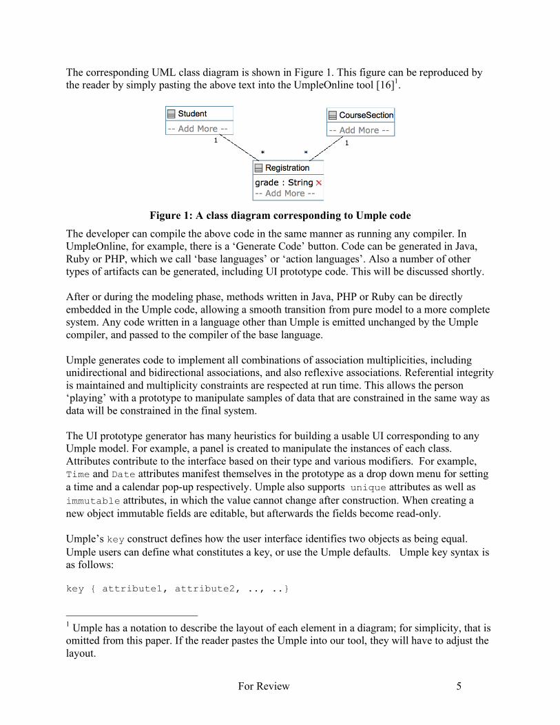
2.2 Class Diagrams The following is an Umple model showing three classes, two associations and one attribute. class Student {} class CourseSection {} class Registration { String grade; // an attribute: get and set methods are generated * -- 1 Student; // an association: A registration has 1 Student * -- 1 CourseSection; // another association }
For Review 5
The corresponding UML class diagram is shown in Figure 1. This figure can be reproduced by the reader by simply pasting the above text into the UmpleOnline tool [16]1.
Figure 1: A class diagram corresponding to Umple code
The developer can compile the above code in the same manner as running any compiler. In UmpleOnline, for example, there is a ‘Generate Code’ button. Code can be generated in Java, Ruby or PHP, which we call ‘base languages’ or ‘action languages’. Also a number of other types of artifacts can be generated, including UI prototype code. This will be discussed shortly. After or during the modeling phase, methods written in Java, PHP or Ruby can be directly embedded in the Umple code, allowing a smooth transition from pure model to a more complete system. Any code written in a language other than Umple is emitted unchanged by the Umple compiler, and passed to the compiler of the base language. Umple generates code to implement all combinations of association multiplicities, including unidirectional and bidirectional associations, and also reflexive associations. Referential integrity is maintained and multiplicity constraints are respected at run time. This allows the person ‘playing’ with a prototype to manipulate samples of data that are constrained in the same way as data will be constrained in the final system. The UI prototype generator has many heuristics for building a usable UI corresponding to any Umple model. For example, a panel is created to manipulate the instances of each class. Attributes contribute to the interface based on their type and various modifiers. For example, Time and Date attributes manifest themselves in the prototype as a drop down menu for setting a time and a calendar pop-up respectively. Umple also supports unique attributes as well as immutable attributes, in which the value cannot change after construction. When creating a new object immutable fields are editable, but afterwards the fields become read-only. Umple’s key construct defines how the user interface identifies two objects as being equal. Umple users can define what constitutes a key, or use the Umple defaults. Umple key syntax is as follows: key { attribute1, attribute2, .., ..}
1 Umple has a notation to describe the layout of each element in a diagram; for simplicity, that is omitted from this paper. If the reader pastes the Umple into our tool, they will have to adjust the layout.
For Review 6
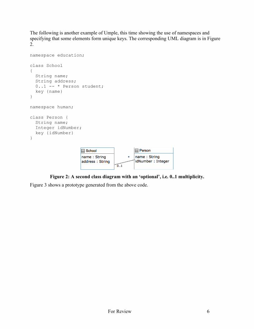
The following is another example of Umple, this time showing the use of namespaces and specifying that some elements form unique keys. The corresponding UML diagram is in Figure 2. namespace education; class School { String name; String address; 0..1 -- * Person student; key {name} } namespace human; class Person { String name; Integer idNumber; key {idNumber} }
Figure 2: A second class diagram with an ‘optional’, i.e. 0..1 multiplicity.
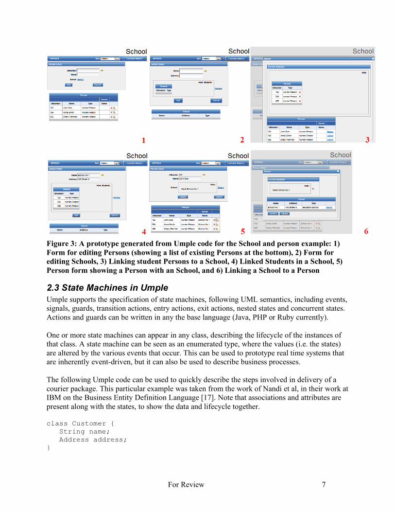
Figure 3 shows a prototype generated from the above code.
For Review 7
Figure 3: A prototype generated from Umple code for the School and person example: 1) Form for editing Persons (showing a list of existing Persons at the bottom), 2) Form for editing Schools, 3) Linking student Persons to a School, 4) Linked Students in a School, 5) Person form showing a Person with an School, and 6) Linking a School to a Person
2.3 State Machines in Umple Umple supports the specification of state machines, following UML semantics, including events, signals, guards, transition actions, entry actions, exit actions, nested states and concurrent states. Actions and guards can be written in any the base language (Java, PHP or Ruby currently). One or more state machines can appear in any class, describing the lifecycle of the instances of that class. A state machine can be seen as an enumerated type, where the values (i.e. the states) are altered by the various events that occur. This can be used to prototype real time systems that are inherently event-driven, but it can also be used to describe business processes. The following Umple code can be used to quickly describe the steps involved in delivery of a courier package. This particular example was taken from the work of Nandi et al, in their work at IBM on the Business Entity Definition Language [17]. Note that associations and attributes are present along with the states, to show the data and lifecycle together. class Customer { String name; Address address; }
For Review 8
class CourierShipment { Time ArrivalTime; Time DeliveryTime; Money price; Boolean billToRecipient; * -- 1 Customer sender; * -- 1 Customer recipient; packageStatus { Initial { createDraft -> Draft; createFinal -> Ready; } Draft { createFinal -> Ready; } Ready { dropAtCourierDepot -> Transit; pickUpByDeliverer -> Picked; } Picked { dropAtCourierDepot -> Transit; } Transit { transferToNextStage -> Transit; deliver -> Delivered; } Delivered { billingSettled -> Done; } Done {} } } State machine events by default are generated in a user-interface prototype as buttons. Clicking a button results in invoking that event, which changes the state. State changes can also be triggered by such events as another attribute reaching a threshold. Transitions, state entries and state exits can also trigger execution of arbitrary code (i.e. actions). Class diagram can have multiple state machines, therefore, an object can be in one or more states at a time. Each state is represented by the state name in the prototype. The prototype keeps track of the event history invoked on the object to allow for analysis of behavior of the system.
2.4 Umple Support for Mixins and Substitution The concept of the mixin was first popularized in the Ada language [18]. It allows independently-developed code to be injected into a set of classes, and thus supports composition of a system. Support for mixins is useful for prototype development because different features can be independently described in Umple and added one-by-one to a base model to explore their ramifications. We illustrate how Umple mixins enhance reusability of components.
For Review 9
As a very simple example, consider the following two blocks of code to be defined in separate files. If these files are compiled together, the result is a class that has two Integer values, x and y. class A { Integer x; } class A { Integer y; } Umple supports an unbounded number of state machines in every class, each of which can be defined independently. The same event in Umple can trigger transitions in one or more state machines. Simple functions defining guards and actions can be reused across a number of state machines, or across classes and components, and again the definitions of these can be defined independently, allowing mixing in of different sets to explore different requirements while prototyping. The following simple example illustrates a traffic control system, where the pedestrian light is dependent on, or controlled by, another state machine controlling the car traffic. For conciseness, we illustrate only part of the model here. class trafficLightSystem { carTraffic { Red { entry / {goingRed();} after(redTimer)[!emergency] -> Yellow; emergencyNotice -> AllRed; } Yellow { … } … } pedestrianTraffic { DontWalk { goingRed [!emergency] -> Walk; emergencyNotice -> DontWalk; } … } … } In this example, the event emergencyNotice triggers a transition in two separate state machines in the same class. Similarly, the guard emergency is used in two transitions in two state machines. The example also shows how an action in one state machine, goingRed(), can function as an event and trigger a transition in an another state machine.
For Review 10
“Reuse of software components in applications still provides some difficulties for a prototyping-based approach” [13]. It is, therefore, our vision to support reuse at various levels of abstraction. We have so far presented one aspect of reuse and mixin in Umple, where more than one state machine can reuse elements and behave interdependently. We now illustrate another mixin aspect, where complete state machines are reused and customized. A traffic light’s basic operation is timer-based transitions from three states, Red, Green, and Yellow. This simple and basic model can initially be implemented as a stand-alone state machine, and later incorporated into various classes: For simplicity, we continue to only present partial models. Statemachine coreTrafficController { Red { After(redTimer) -> Green; } Green { After(greenTimer) -> Yellow; } Yellow { After(yellowTimer) -> Red; } } In systems where a basic traffic light is desired, the previous standalone state machine can be referenced as follows: Class TrafficLightController { northSouthController as coreTrafficController; eastWestController as coreTrafficController; } This example creates state machines called northSouthController and eastWestController that behave identically to the coreTrafficController state machine. Some traffic lights may have additional states, like flashing red, or flashing yellow, that are not part of the basic traffic light behavior. Let’s call this type of traffic light FrFy for short. Adding such a feature can be accomplished as follows: Class TrafficLightController { FrFy as coreTrafficController { Red { + midnightHour -> FlashingRed; } FlashingRed { morningHour -> Red; } } }
For Review 11
The previous example illustrates a scenario of adding to a basic state machine. The next example illustrates removing and modifying existing elements of a state machine. Let’s assume now we are modeling a traffic light for a highway entrance, and that the light is either Red or Green. We call this traffic light HWay for short. class TrafficLightController { HWay as coreTrafficController { Green { - After(greenTimer) -> Yellow; After(greenTimer) -> Red; } } } This example illustrates a scenario where a transition is removed and replaced. The process of modeling and prototyping controllers may reveal a number of reusable state machines. The Umple Eclipse-based textual editor supports a features that are geared towards modeling. For example, the outline view allows the modeler to easily locate and select state machines and expose, or hide, their internal elements. The mixin and reuse features described above, combined with a textual modeling approach, enable modelers to quickly draft, and iteratively refine, a model. A prototype can be generated at any stage of this process to instantiate the model and explore its run-time manifestation.
2.5 The Umple Prototype Generator As discussed above, at any point in the modeling or development activities, the user can automatically generate a system prototype that allows the user to interact with the system. The prototype generation process is fully automated with development intervention limited to specifying a few preferences. Since defaults are available for the preferences, prototype generation can involve zero effort. The system prototype has the following features: 1. It allows the user to create instances of classes (objects) and links of associations 2. Semantic rules are respected at run time. For example, an error message is displayed if the
user attempts to create an object that results in a violation of the multiplicity of an association.
3. The user can view and update an object’s attributes. 4. The user can follow links. 5. The user can interact with system objects using the exposed public functions. 6. View the history of events and current status of objects with state machines. 7. The user can change the system’s look and feel by applying predefined themes [14]. An example generated prototype is illustrated in Figure 3.
For Review 12
2.6 Collaboration Support due to the Textual Notation The Umple platform uses the textual notation, which facilitates for versioning and merging of models. This in turn helps evolve prototypes in an orderly manner, and contrasts with the XMI representation of most visual modeling tools. Note that the generated prototypes need not be versioned since they are automatically and entirely generated from Umple models.
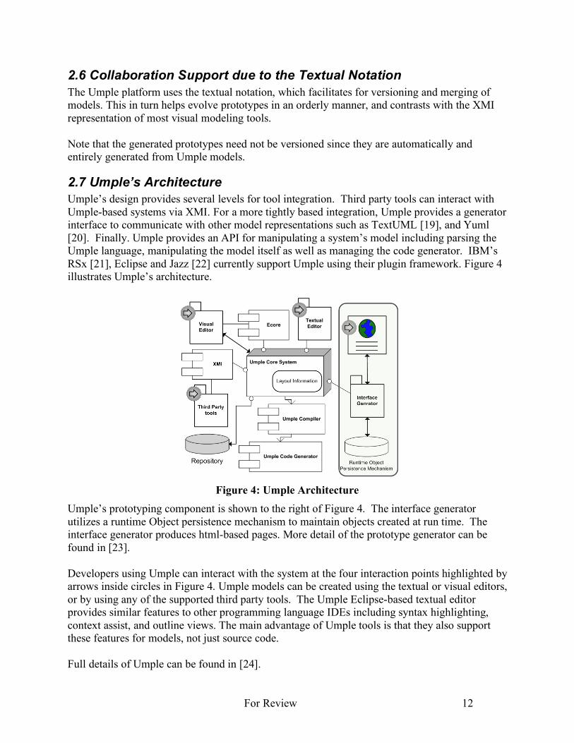
2.7 Umple’s Architecture Umple’s design provides several levels for tool integration. Third party tools can interact with Umple-based systems via XMI. For a more tightly based integration, Umple provides a generator interface to communicate with other model representations such as TextUML [19], and Yuml [20]. Finally. Umple provides an API for manipulating a system’s model including parsing the Umple language, manipulating the model itself as well as managing the code generator. IBM’s RSx [21], Eclipse and Jazz [22] currently support Umple using their plugin framework. Figure 4 illustrates Umple’s architecture.
Figure 4: Umple Architecture
Umple’s prototyping component is shown to the right of Figure 4. The interface generator utilizes a runtime Object persistence mechanism to maintain objects created at run time. The interface generator produces html-based pages. More detail of the prototype generator can be found in [23]. Developers using Umple can interact with the system at the four interaction points highlighted by arrows inside circles in Figure 4. Umple models can be created using the textual or visual editors, or by using any of the supported third party tools. The Umple Eclipse-based textual editor provides similar features to other programming language IDEs including syntax highlighting, context assist, and outline views. The main advantage of Umple tools is that they also support these features for models, not just source code. Full details of Umple can be found in [24].
For Review 13
3. Related Work There is increasing attention towards the generation of prototypes and user interfaces from UML models. Elkoutbi et al [25] describe an approach where user interfaces can be generated from state machine models that are in turn generated from annotated UML scenario diagrams. Their approach focuses on states and messages in the process of generating prototypes. Approaches, such as StateMate [26] focus on the dynamics or behavior of the system only, without considering the data, or other aspects of the system. On the other hand, Janssen and Balzert [27, 28] use data structure specifications for UI generation. Li et al [29] generate prototypes from use cases. The use case actions can create or delete objects; the prototype will check for association validity. These approaches are generally only focused on prototyping the objects and associations of the system. Umple combines both approaches into one complete prototyping capability: the system’s data structure and integrity, as well as the system’s dynamic behavior. A number of prototyping approaches require additional information specific for prototype generation [30]. Such approaches are particularly challenging in model-driven development environments. User-interface specific information is generally not managed within the modeling environment. For example, when models evolve, such information needs to be manually added during model transformation. This has significant implications on the cost of developing prototypes. Homrighausen et al. [31] proposed a round-trip prototyping approach where manual changes to the prototype during validation are automatically fed back into the requirements specifications. While there are a number of textual modeling approaches and tools [32-35], Umple’s prototype generation from textual UML models with embedded implementation code is unique. Umple takes the stand of generating prototypes on the fly, as a side effect. The user is not expected to add any specific information to drive the prototype development process. By embedding algorithmic code within Umple models, developers are more likely to maintain and evolve the code as the system matures.
4. Conclusions We have presented Umple, a tool that supports rapid modeling and rapid prototyping of systems from UML class and state machine models. The highly abstract textual notation allows Umple users to quickly draft models, generate code and utilize capabilities such as mixins to explore various alternative designs. Umple approach merges models, and code, and generates system prototypes that closely reflect the internal system components and demonstrate system behavior. It merges modeling abstractions and implementation code with the objective of enhancing incremental refinement of models and prototypes.
For Review 14
References [1] Forward, A., Lethbridge, T.C., and Brestovansky, D. (2009), “Improving Program Comprehension by
Enhancing Program Constructs: An Analysis of the Umple language”, International Conference on Program Comprehension (ICPC) 2009, Vancouver, IEEE, pp. 311-312.
[2] Lethbridge, T.C., Forward, A. and Badreddin, O. (2010), “Umplification: Refactoring to Incrementally Add Abstraction to a Program”, Working Conference on Reverse Engineering (IWPC), Boston, October 2010, IEEE, pp. 220-224.
[3] H. F. Hofmann and F. Lehner (2001) "Requirements engineering as a success factor in software projects", IEEE Software pp. 58-66.
[4] Memmel, T., Gundelsweiler, F. and Reiterer, H. (2007) "Agile human-centered software engineering," 21st British CHI Group Annual Conference on HCI 2007: People and Computers XXI: HCI... but Not as we Know it-Volume 1, pp. 167-175.
[5] Hunt, A., Thomas, D., (2001) “The Art in Computer Programming”, Developer.*, http://www.developerdotstar.com/mag/articles/art_computer_programming.html
[6] Chua, C., Leong, K., Lim, C., (2003) Rapid Prototyping: Principles and Applications. London, U.K: World Scientific.
[7] Alavi, M., (1984) “An assessment of the prototyping approach to information systems development”, Communications of the ACM, vol 27, pp. 556-563.
[8] Lim, Y-K., Stolterman, E., and Tenenberg, J., (2008) “The Anatomy of Prototypes: Prototypes as Filters, Prototypes as Manifestations of Design Ideas” ACM Transactions on Computer-Human Interaction, Vol. 15, No. 2, Article 7, July, pp. 7:1-7:25.
[9] Forward, A. and Lethbridge, T. C. (2008) "Problems and opportunities for model-centric versus code-centric software development: A survey of software professionals," MiSE '08: International Workshop on Models in Soft-ware Engineering, pp. 27-32.
[10] Medvidovic, N., Egyed, A. and Rosenblum, D. S. (1999) “Round-trip software engineering using UML: From architecture to design and back,” Second International Workshop on Object-Oriented Reengineering (WOOR’99), Toulouse, France,
[11] Farah, H. and Lethbridge, T. C. (2007) "Temporal exploration of software models: A tool feature to enhance software under-standing," WCRE 2007, pp. 41-49.
[12] Jones, M. C., Floyd, I. R. and Twidale, M. B., (2007) "Patchwork prototyping with open-source software," Handbook of Research on Open Source Software, IGI Global, pp. 126-141.
[13] Kordon, F., Luqi, (2002) “An introduction to rapid system prototyping” IEEE Trans.Software Eng, 28, 9, pp. 817-821.
[14] Forward, A., Badreddin, O., and Lethbridge T.C. (2010), “Umple: Towards Combining Model Driven with Prototype Driven System Development”, 21st IEEE International Symposium on Rapid System Prototyping, Fairfax VA, June.
[15] G. Pomberger, W. Bischofberger, D. Kolb, W. Pree and H. Schlemm. (1991) “Prototyping-Oriented Software Development - Concepts and Tools”, Structured Programming, vol 12, pp. 43-60.
[16] University of Ottawa, “UmpleOnline,” accessed 2010, http://cruise.site.uottawa.ca/umpleonline/ [17] Nandi, P., et al., (2010) “Data4BPM: Introducing business entities and the business entity definition
language (BEDL)”, IBM developerWorks, http://www.ibm.com/developerworks/websphere/library/techarticles/1004_nandi/1004_nandi.html
[18] E. Seidewitz. (1992) "Object-oriented programming with mixins in Ada". ACM SIGAda Ada Letters vol 12, pp. 76-90.
[19] Chaves, R. “TextUML”, accessed 2010, http://abstratt.com/ [20] Harris, T. " YUML", accessed 2010, http://yuml.me/ [21] IBM, “IBM Rational Software Architect Modeling Tool", accessed 2010, http://www-
01.ibm.com/software/awdtools/architect/swarchitect/ [22] IBM, “IBM Rational Jazz technology platform”, accessed 2010, http://www-
01.ibm.com/software/rational/jazz/
For Review 15
[23] Solano, J. (2010) “Exploring how model oriented programming can be extended to the UI level”, Masters Thesis, University of Ottawa. Available: http://www.site.uottawa.ca/~tcl/gradtheses/jsolano/
[24] Forward, A. (2010) “The Convergence of Modeling and Programming: Facilitating the Representation of Attributes and Associations in the Umple Model-Oriented Programming Language”, PhD Thesis, University of Ottawa. Available: http://www.site.uottawa.ca/~tcl/gradtheses/aforwardphd/
[25] M. Elkoutbi, I. Khriss and R. K. Keller. (2006) “Automated prototyping of user interfaces based on UML scenarios”, Autom. Software. Eng vol 13, pp. 5-40.
[26] IBM, “Rational StateMate”, accessed 2010, http://www-01.ibm.com/software/awdtools/statemate/ [27] Janssen, C., Weisbecker, A. and Ziegler, J. (1993) “Generating user interfaces from data models and
dialogue net specifications,” Proceedings of the INTERACT'93 and CHI'93, pp. 418-423. [28] H. Balzert. (1996) “From OOA to GUIs: The Janus system”, JOOP vol 8, pp. 43-47. [29] X. Li, Z. Liu, J. He and Q. Long, (2004) “Generating a Prototype from a UML Model of System
Requirements,” ICDCIT, LNCS 3347, Springer, pp. 255–265.. [30] M. Elkoutbi and R. K. Keller (2000), “User interface prototyping based on UML scenarios and high-
level Petri nets”, Application and Theory of Petri Nets 2000 (Proc. of 21 st Intl. Conf. on ATPN), Springer LNCS 1825, pp. 166-186.
[31] A. Homrighausen, H. W. Six and M. Winter (2002) “Round-trip prototyping based on integrated functional and user interface requirements specifications”, Requirements Engineering vol 7, pp. 34-45.
[32] “ModSL - text-to-diagram UML sketching tool”. Accessed 2010: http://code.google.com/p/modsl/. [33] A. Fadila and G. Said. (2006) “A new textual description for software process modeling”,
Information Technology Journal vol 5, pp. 1146-1148. [34] G. Fliedl, C. Kop and H. C. Mayr. (2005) “From textual scenarios to a conceptual schema”, Data.
Knowl. Eng. vol 55, pp. 20-37. [35] OMG, “Human-Usable Textual Notation,” accessed 2010, http://www.omg.org/spec/HUTN/