design of anthropomorphic flow phantoms based on rapid prototyping of compliant vessel geometries
TRANSCRIPT

Ultrasound in Med. & Biol., Vol. 39, No. 9, pp. 1654–1664, 2013Copyright � 2013 World Federation for Ultrasound in Medicine & Biology
Printed in the USA. All rights reserved0301-5629/$ - see front matter
/j.ultrasmedbio.2013.03.015
http://dx.doi.org/10.1016d Original Contribution
DESIGN OFANTHROPOMORPHIC FLOW PHANTOMS BASED ON RAPIDPROTOTYPING OF COMPLIANT VESSEL GEOMETRIES
SIMON S. M. LAI, BILLY Y. S. YIU, ALEXANDER K. K. POON, and ALFRED C. H. YU
Medical Engineering Program, University of Hong Kong, Pokfulam, Hong Kong SAR, China
(Received 29 August 2012; revised 25 February 2013; in final form 9 March 2013)
AKong,
Abstract—Anatomically realistic flow phantoms are essential experimental tools for vascular ultrasound. Here wedescribe how these flow phantoms can be efficiently developed via a rapid prototyping (RP) framework thatinvolves direct fabrication of compliant vessel geometries. In this framework, anthropomorphic vessel modelswere drafted in computer-aided design software, and they were fabricated using stereolithography (one type ofRP). To produce elastic vessels, a compliant photopolymer was used for stereolithography. We fabricated a seriesof compliant, diseased carotid bifurcation models with eccentric stenosis (50%) and plaque ulceration (types I andIII), and they were used to form thin-walled flow phantoms by coupling the vessels to an agar-based tissue-mimicking material. These phantoms were found to yield Doppler spectrograms with significant spectral broad-ening and color flow images withmosaic patterns, as typical of disturbed flow under stenosed and ulcerated diseaseconditions. Also, their wall distension behavior was found to be similar to that observed in vivo, and this corre-sponded with the vessel wall’s average elastic modulus (391 kPa), which was within the nominal range for humanarteries. The vessel material’s acoustic properties were found to be sub-optimal: the estimated average acousticspeed was 1801 m/s, and the attenuation coefficient was 1.58 dB/(mm$MHzn) with a power-law coefficient of0.97. Such an acoustic mismatch nevertheless did not notably affect our Doppler spectrograms and color flowimage results. These findings suggest that phantoms produced from our design framework have the potential toserve as ultrasound-compatible test beds that can simulate complex flow dynamics similar to those observed inreal vasculature. (E-mail: [email protected]) � 2013 World Federation for Ultrasound in Medicine & Biology.
Key Words: Vascular ultrasound, Anthropomorphic flow phantom, Compliant vessels, Rapid prototyping,Stereolithography.
INTRODUCTION
For more than two decades, flow phantoms have beenplaying a pivotal role in fostering the technical advance-ment of Doppler ultrasound by providing an experimentalmeans of simulating vascular flow conditions similar tothose seen in vivo (Hoskins 2008). These devices gener-ally comprise a vessel model embedded within a tissue-mimicking material, and a flow pump that is used to driveblood-mimicking fluid through the vessel (Ramnarineet al. 1998, 2001). From a quality assurance standpoint,flow phantoms have been widely deployed as calibrationplatforms to characterize the performance of Dopplerultrasound instruments (Marinozzi et al. 2012). Theyhave also been used to help identify sources of measure-ment errors (Lui et al. 2005; Steinman et al. 2001, 2005)and to evaluate the sensitivity of new flow estimation
ddress correspondence to: Alfred C. H. Yu, University of HongPokfulam, Hong Kong SAR, China. E-mail: [email protected]
1654
indices (Dubiel et al. 2006; Raine-Fenning et al. 2008a,2008b). In addition to these conventional applications,there is an emerging interest in using flow phantoms asinvestigative tools to explore novel ways of using ultra-sound to quantitatively assess complex hemodynamicpatterns under different pathological conditions such asstenosis and plaque ulceration (Poepping et al. 2010;Wong et al. 2009). For the latter application, it is imper-ative to design anthropomorphic (i.e., anatomically real-istic) flow phantoms that can precisely mimic thehemodynamics of various vascular morphologies so thatnew ultrasonic measurement strategies developed fromthese phantom studies can be translated into clinical diag-noses in vivo.
Unlike straight-vessel phantoms that can be readilycreated using off-the-shelf tubing materials, anthropo-morphic flow phantoms generally require reconstructionof vessel geometries that closely follow real vascularanatomy (Hoskins 2008). Such reconstruction conven-tionally involves the use of investment casting principles

Anthropomorphic flow phantoms with compliant vessels d S. S. M. LAI et al. 1655
in which a negative mold of the arterial geometry iscreated and then used to form a replica of the vesselcore for casting within a tissue-mimicking material(Poepping et al. 2002, 2004). This technique has beenshown to be useful in producing wall-less phantomswhereby the vessel core is removed after tissue casting(Meagher et al. 2007; King et al. 2010; Watts et al.2007). It has also been used to fabricate thin-walled phan-toms that comprise replicas of the vessel wall as opposedto the vessel core (Dingley et al. 2006; King et al. 2011;O’Flynn et al. 2005). Nevertheless, this way of producinganthropomorphic flow phantoms is known to be techni-cally cumbersome, as investment casting is after alla multi-step process that requires skilled craftsmanship(Wong et al. 2008). As such, it is inherently difficult touse this technique to pursue large-scale production ofa range of phantoms with multi-factor variations in path-ological parameters, as would be needed for facilitatinglongitudinal investigations of novel vascular ultrasoundmeasurement strategies.
The aim of this work is to devise an efficient frame-work for developing anthropomorphic flow phantoms tosupport application development efforts in vascular ultra-sound. We have been working with the proposition thatdirect fabrication of authentic vessel geometries can berealized using computer-aided rapid prototyping (RP)technologies like stereolithography in view of theirincreasing technical maturity in recent years (Lantadaand Morgado 2012; Rengier et al. 2010). Moreover, it isour hypothesis that anthropomorphic vessel tubes withelastic moduli similar to those of real arteries may begenerated with the use of compliant photopolymers thathave recently emerged as a new class of stereolithographymaterial (Berselli et al. 2011). Note that, in the context offlow phantom design, computer-aided manufacturing hasbeen previously introduced at a limited scale to machinenegative molds for investment casting (O’Flynn et al.2005; Poepping et al. 2002, 2004) and to create masterpatterns of artery models for silicone mold imprinting(King et al. 2010, 2011; Meagher et al. 2007; Wattset al. 2007). Computerized milling of wall-less phantomshas also been attempted using rigid materials (Wong et al.2008). In contrast, this work distinguishes itself fromthese early efforts by providing a novel perspective onhow elastic thin-walled phantoms can be efficientlyproduced without resorting to the investment castingtechnique.
DESIGN METHODS
Drafting of vessel geometry modelsOur new phantom design framework first involves
the use of computer-aided design software (SolidWorks;Dassault Systemes, Waltham, MA, USA) to draft 3-D
models of anthropomorphic vessel geometries. To serveas illustration, generalized models of the carotid bifurca-tion were developed in this work. As shown in Figure 1a,the lumen diameters used in our models were 6.0, 4.2 and3.5 mm, respectively for the common carotid artery(CCA), internal carotid artery (ICA) and external carotidartery (ECA).Wall thickness was set to 0.8 mm as consis-tent with real carotid arteries (Poepping et al. 2004). Also,inlet and outlet flow connectors were included in thevessel models to facilitate mounting of the vessel tubesduring flow phantom fabrication.
The overall geometry of our demonstration proto-types can be considered as a modified version ofa tuning-fork model that was originally reported formagnetic resonance imaging studies (Smith et al. 1999).The ratio of the CCA, ICA and ECA diameters waskept the same, but we used different vessel sizes (e.g.,CCA diameter was 6 mm compared with 8 mm in theoriginal geometry [Smith et al. 1999]) to more closelyreflect the mean carotid artery diameter of adults(Krejza et al. 2006). Another modified feature is thatmultiple diseased vascular conditions were concurrentlyincorporated into the models to demonstrate the abilityof RP to fabricate complex vessel geometries that deviatefrom the typical straight-tube appearance. One of theseconditions is arterial stenosis, and it was incorporatedinto the vessel models by introducing an eccentric nar-rowing at the inlet to the ICA branch. A stenosis levelof 50% was considered in this work, and it was specifiedaccording to the definition used for the North AmericanSymptomatic Carotid Endarterectomy Trial (Smithet al. 1996). The second diseased condition included inour geometries was plaque ulceration, and two shapeswere considered: (i) hemisphere with 3.85-mm orificediameter (Fig. 1b); (ii) ellipsoid with major-axis lengthof 7.37 mm, minor-axis length of 2.95 mm and 45� angletilt toward the ICA distal end (Fig. 1c). In our models, theulcer was placed on the proximal side of the ICA narrow-ing (i.e., the side facing the CCA) as this is the site offrequent occurrence of ulceration (Lovett and Rothwell2003). It should be noted that the two ulcer shapes consid-ered in this work are respectively classified as types I andIII (Lovett et al. 2004), and they were chosen becausethey are known to lead to significantly disturbed flowbehavior (Wong et al. 2009).
Note that carotid bifurcation models were chosen tobuild our demonstration prototypes because they are ofpractical relevance to carotid ultrasound studies. Inparticular, it is well recognized that an effective phantomfabrication framework is warranted to foster systematicdevelopment of new clinical strategies in using carotidultrasound to diagnose various pathophysiological factors(Grant et al. 2003; Wong et al. 2008). Another pointworth noting is that our demonstration prototypes were

Fig. 1. Carotid bifurcation vessel tubes produced using stereolithography and compliant photopolymers. Three differentgeometries were fabricated: (a, d) without stenosis and ulcers; (b, e) with 50% eccentric stenosis at the ICA inlet anda hemispheric (type I) plaque ulcer; and (c, f) with 50% stenosis and a distally pointing ellipsoidal (type III) plaque ulcer.(a–c) Computer-aided design models of vessel geometries. (d–f) Photographs of the fabricated stereolithography-produced vessel tubes. CCA 5 common carotid artery, ECA 5 external carotid artery, ICA 5 internal carotid artery.
1656 Ultrasound in Medicine and Biology Volume 39, Number 9, 2013
based on the co-planar form of the carotid bifurcationmodel. Such a design choice was made by taking intoaccount that the dominant flow patterns of this modelare known to be generated along the central plane(Poepping et al. 2010).
Stereolithography production of vessel tubesTo facilitate RP of vessel geometries, a stereolithog-
raphy input file (of STL format) was first created foreach model drafted in SolidWorks. With the STL files,production of vessel tubes was then performed using
a stereolithography machine (Eden 350V; Objet Geome-tries, Rahovot, Israel) with build resolutions of 16 and42 mm, respectively, for layer thickness and along eachlayer plane. Fabrication of non-rigid vessel tubes wasmade possible with the use of a compliant photopolymermaterial for stereolithography (FullCure 930; ObjetGeometries). During the printing process, the compliantphotopolymer was deposited at coordinates correspond-ing to the 3-D vessel models, and a gel-like supportingphotosensitive resin (FullCure 705; Objet Geometries)was concurrently deposited inside the vessel lumen and

Anthropomorphic flow phantoms with compliant vessels d S. S. M. LAI et al. 1657
around the vessel tube to provide structural support to theraw stereolithography builds. Note that multiple vesselswere fabricated in one batch given the relatively largeprinting tray size of the stereolithography machine(340 3 340 3 200 mm). To obtain the compliant vesseltubes from the stereolithography builds, the supportingmaterial were removed after the printing process. Thiswas carried out by first soaking the supporting layers(via immersion of the stereolithography builds in deion-ized water for at least 3 h) and then gently rinsing themoff the vessel tubes.
Flow phantom developmentEach stereolithography-produced compliant vessel
tube, as illustrated in Figure 1(d–f) for different carotidbifurcation geometries, was mounted onto an acrylicbox with flow connectors installed at the ends and withacoustic absorber placed at the bottom. The mountedtube was in a co-planar orientation parallel to the verticalaxis. Subsequently, a tissue-mimicking material was castaround the mounted vessel tubes. An agar-based mixturewas used as the tissue mimic in this work. It was based onan in-house formula that we developed with 85.1%distilled water, 3.0% agar (A1296; Sigma-Aldrich,St. Louis, MO, USA), 11.1% glycerol (G7757; Sigma-Aldrich), 0.5% silicon dioxide (S5631; Sigma-Aldrich),and 0.3% potassium sorbate preservatives (85520;Sigma-Aldrich). The agar mixture was allowed to set inroom temperature for at least 6 h.
Connection to flow pump systemTo put the flow phantom into operation, a computer-
controlled gear pump system (AccuFlow-Q; ShelleyMedical Imaging, London, ON, Canada) was used tosupply pulsatile flow into the phantom inlet. The blood-mimicking fluid that we used in this work (BMF-US;Shelley Medical Imaging) was a nylon-scatterer solutionwith an acoustic speed of 1548 m/s, density of1037 kg/m3 and kinematic viscosity of 3.95 3 1026
m2/s (Ranmarine et al. 1998). Flow resistors in the formof 2 mm-diameter tubing (i.e., narrower than both theICA and ECA) were connected to the two vessel outlets.The flow division ratio between the ICA and ECAbranches was calibrated to be 2:1 by using flow resistortubing lengths 1 and 2 m long, respectively, for the twobranches (confirmed by manual measurements).
In our experiments, we used a carotid pulse wave-form with a pulse-cycle frequency of 1.2 Hz (i.e., simu-lating a heart rate of 72 beats/min), and the averageoutflow rate was manually measured to be 4.5 mL/s basedon a systolic pump output of 14 mL/s. The intra-luminalpressure at the flow inlet was confirmed to exhibit apattern with dicrotic notch, as visualized using anin situ pressure monitor setup that comprises a pressure
transducer (6199; Utah Medical Products, Midvale, UT,USA) and a patient monitoring module (CMS-2001; Phi-lips Medical Systems, Anhover, MA, USA). Note that,given our choice of parameters, the average Reynoldsnumber was 242 in the CCA branch, and the Womersleynumber was 4.14. These values were estimated on thebasis of established formulas that respectively relateflow velocity, tube diameter and kinematic viscosity(for Reynolds number), as well as tube radius, pulsefrequency and kinematic viscosity (for Womersleynumber) (Evans and McDicken 2000).
EXPERIMENTAL METHODS
Spectral Doppler and color flow imaging: Investigationof flow dynamics
To gain insight into the operational performance ofour phantoms, we used the pulsed Doppler mode andcolor flow imaging mode of a research-purpose ultra-sound scanner (SonixTouch; Ultrasonix, Richmond,BC, Canada) to evaluate the temporal and spatialdynamics of flow pattern inside the vessel lumen. Ouremphasis was on the ICA branch of the phantom, as thestenosis and ulcers were placed at the ICA inlet in ourvessel models and disturbed flow is expected to emergewithin this branch (Wong et al. 2009). For the pulsedDoppler measurements, a linear array (L14–5; Ultraso-nix) was used as the transducer, and the range gate(2.0 mm in size) was centered at the distal end of theICA lumen (ultrasound frequency: 4 MHz, pulse repeti-tion frequency [PRF]: 4 kHz, wall filter cut-off: 80 Hz,beam-flow angle: 75�). Measurements were also madeunder the same settings in the CCA branch to facilitatecomparative assessment. For color flow imaging, thesame transducer was used, and the color box coveredthe entire ICA branch (ultrasound frequency: 5 MHz,PRF: 2.5 kHz, wall filter cut-off: 75 Hz, slow-timeensemble size: 10 samples). Other imaging settingssuch as time-gain compensation, focal depth, displaydynamic range and image filters were adjusted as neces-sary to improve the visualization quality.
Tissue Doppler: Distension characteristics analysisTo determine whether the compliant vessel tubes
would distend in a manner similar to that of humanarteries, we measured the distension waveform (i.e.,temporal variation of lumen diameter) in the CCA branchwhen the phantom was operating under pulsatile flow. Inapproaching this task, the tissue Doppler technique wasemployed (Evans and McDicken 2000). We first usedthe SonixTouch scanner to acquire M-mode RF dataover a beamline that was placed perpendicular to theCCA vessel wall (ultrasound frequency: 5 MHz; PRF:500 Hz; pulse length: three cycles). Wall distension

1658 Ultrasound in Medicine and Biology Volume 39, Number 9, 2013
estimation was then performed by processing theacquired RF data with a MATLAB (MathWorks, Natick,MA, USA) script that operated as follows. First, complexdemodulation was applied to each RF ensemble. From thedemodulated data, the slow-time ensemble was then ex-tracted at two 1.0 mm-sized range gates that were respec-tively centered at the proximal and distal walls of theCCA. After that, low-pass finite impulse response (FIR)filtering (cut-off frequency: 50 Hz) was applied to thetwo slow-time ensembles to suppress blood flow echoes.The mean phase shift induced through wall motion wassubsequently estimated by applying the lag-one autocor-relation algorithm (Evans and McDicken 2000) to thefiltered data, and each estimate was converted intoa displacement value via Doppler relations. To track thetemporal dynamics of wall displacement over variousphases of the pulse cycle, a sliding window estimationstrategy was employed (window size: 64 samples, with87.5% overlap between sliding steps), and the displace-ment estimates for the two walls as obtained at differenttime points over the pulse cycle were summed to obtainthe CCA’s temporal distension waveform. Note that theanalysis was repeated at 10 non-overlapping beamlines.
Tensile testing: Measurement of mechanical propertiesTo characterize the elastic strength of the vessel
tubes, we conducted a series of uniaxial tensile tests onthe compliant photopolymer that we used as vessel wallmaterial. In approaching this analysis, dumbbell-shapedtest strips of the photopolymer material were first fabri-cated with the stereolithography machine. Each of thesestrips were 61 mm in total length; its center part fortensile testing and the two machine gripping ends wererespective of 20 3 10 3 2 mm and 13 3 25 3 4 mm indimensions (length 3 width 3 height) 30 strips weremade in total, and they were kept hydrated before tensiletesting by immersing in deionized water as this wouldbetter reflect the actual condition under which the vesseltubes would operate.
The elastic modulus of the compliant photo-polymer was estimated by computing the derivative ofstress-strain curves obtained from uniaxial tensile testsconducted using a machine that was equipped witha 2-kN-load cell (5848; Instron, Norwood, MA, USA).In each trial, the test strip was first mounted onto themachine grips under zero-strain settings (the corre-sponding gauge length was determined to be 60 mm).Elongation loading was then applied to the strip ata feed rate of 40 mm/min. Consistent with protocols re-ported earlier (Dingley et al. 2006; King et al. 2011),five preconditioning stress-strain cycles were adminis-tered (from 0% to 80% strain) before proceeding withelongation of the test strip to the break point. The cor-responding load-extension curve was acquired and was
converted into a stress-strain curve using MATLAB.Subsequently, the incremental elastic modulus of thesample was determined as the instantaneous slope ofthe stress-strain curve.
Pulse transmission measurements: Characterizationof acoustic properties
The acoustic speed of the compliant photopolymerwas determined using an insertion-based measurementtechnique. This estimation process, the underlying princi-ples of which are described elsewhere (Zell et al. 2007),involved measuring the changes in time-of-flight (TOF)between a transducer pair upon inserting test samples ofdifferent thicknesses. To facilitate analysis, we prepareda set of test slabs of the compliant photopolymer usingthe stereolithography machine. Four different thicknesseswere considered: 2, 4, 6 and 8 mm. Consistent withthe sample preparation protocol for mechanical testing,the test slabs used for acoustic property measurementswere kept under hydrated conditions before the experi-ments. Similar measurements were also made on ouragar-based tissue-mimicking material.
Our measurement setup comprised an axiallyaligned pair of transducers with 5-MHz center frequency(C567-SM; Olympus NDT, Waltham, MA, USA) thatwere spaced 10 cm apart and were placed in a 25�C waterbath (degassed for at least 3 h before the experiment). Thetransmission transducer was driven by an arbitrary wave-form generator (33120A; Agilent Technologies, PaloAlto, CA, USA) that fed pulses with 20-cycle durationand 5-MHz frequency, whereas the reception transducerwas connected to a pulse receiver (5800PR; OlympusNDT) for signal conditioning. The resulting receivedsignal, synchronized with the reference signal from thewaveform generator, was displayed on an oscilloscope(DSO5014A; Agilent Technologies), from which theTOF was measured using on-screen cursors. To estimatethe acoustic speed, a linear regression was performed onthe TOF measurements of the four slab thicknesses, andthe resulting slope was substituted into an establishedformula to arrive at the estimated value (Zell et al.2007). Measurements were repeated for 40 sets of testslabs with the four thicknesses.
With the same measurement setup, the acousticattenuation coefficient was determined through anamplitude-thickness regression approach. In accordancewith principles described elsewhere (Poepping et al.2004), the estimation process involved measuring thereceived signal’s logarithmic amplitude for differentsample thicknesses and calculating their resulting linearfitting slopes. The measurement was performed at a rangeof frequencies (2–5 MHz) to study the frequency depen-dence of acoustic attenuation according to the power lawa5 aof
n, where ao and n are, respectively, the attenuation

Anthropomorphic flow phantoms with compliant vessels d S. S. M. LAI et al. 1659
coefficient and the power coefficient. This fitting wasrepeated over seven sample batches, each of whichcomprised six sets of test slabs.
EXPERIMENTAL RESULTS
Visualization of post-stenotic flow disturbancesOur RP framework was found to be capable of
producing anthropomorphic flow phantoms withdisturbed flow patterns typical of those found in
Fig. 2. Doppler spectrograms obtained from rapid prototyping-produced phantoms for a range gate placed downstream from thestenosis site (each dot on horizontal axis indicates 0.5 s). Resultsare shown for vessel models with: (a) no stenosis; (b) 50%stenosis and type I ulcer; and (c) 50% stenosis and type III ulcer.The range gate position for each spectrogramwas depicted in theinset of each subplot. Spectral broadening can be observed for
the diseased vessel models with stenosis and ulceration.
a stenosed carotid bifurcation with plaque ulcers. Thisis reflected in Figure 2 that shows the pulsed Dopplerspectrograms for diseased bifurcation models with 50%stenosis and type I/III ulcers (results for an unstenosedmodel are also shown as a reference). It is evident thatin these models, the flow profile in the ICA branch (down-stream from the stenosis site) is more disturbed, as re-flected by the significant spectral broadening, especiallyduring systole (see Fig. 2b and 2c).
In line with the Doppler ultrasound measurements,color flow image features that are characteristic ofdiseased vessels were observed in our phantoms. Asshown in Figure 3, for vessel geometries with stenosisand plaque ulceration, their corresponding coloringpattern in the ICA branch for image frames acquiredduring systole had a mosaic appearance (see Fig. 3b,3c) that was not found in the unstenosed model (seeFig. 3a). This mosaic color pattern represents significantspatial variations in velocity, as would be expected forpost-stenotic flow patterns.
Vessel distension in the common carotid artery branchVessel distension was observed in our phantoms as
expected with our use of a compliant vessel wall material.
Fig. 3. Ultrasound color flow images for different rapidprototyping-produced vessel geometries during the systolicphase of a carotid pulse cycle. Difference in coloring patterncan be observed between (a) the unstenosed vessel model andthe 50% stenosis vessel models with (b) type I ulcer and (c)type III ulcer. Mosaic coloring pattern can be found in the
stenosed and ulcerated bifurcation models.
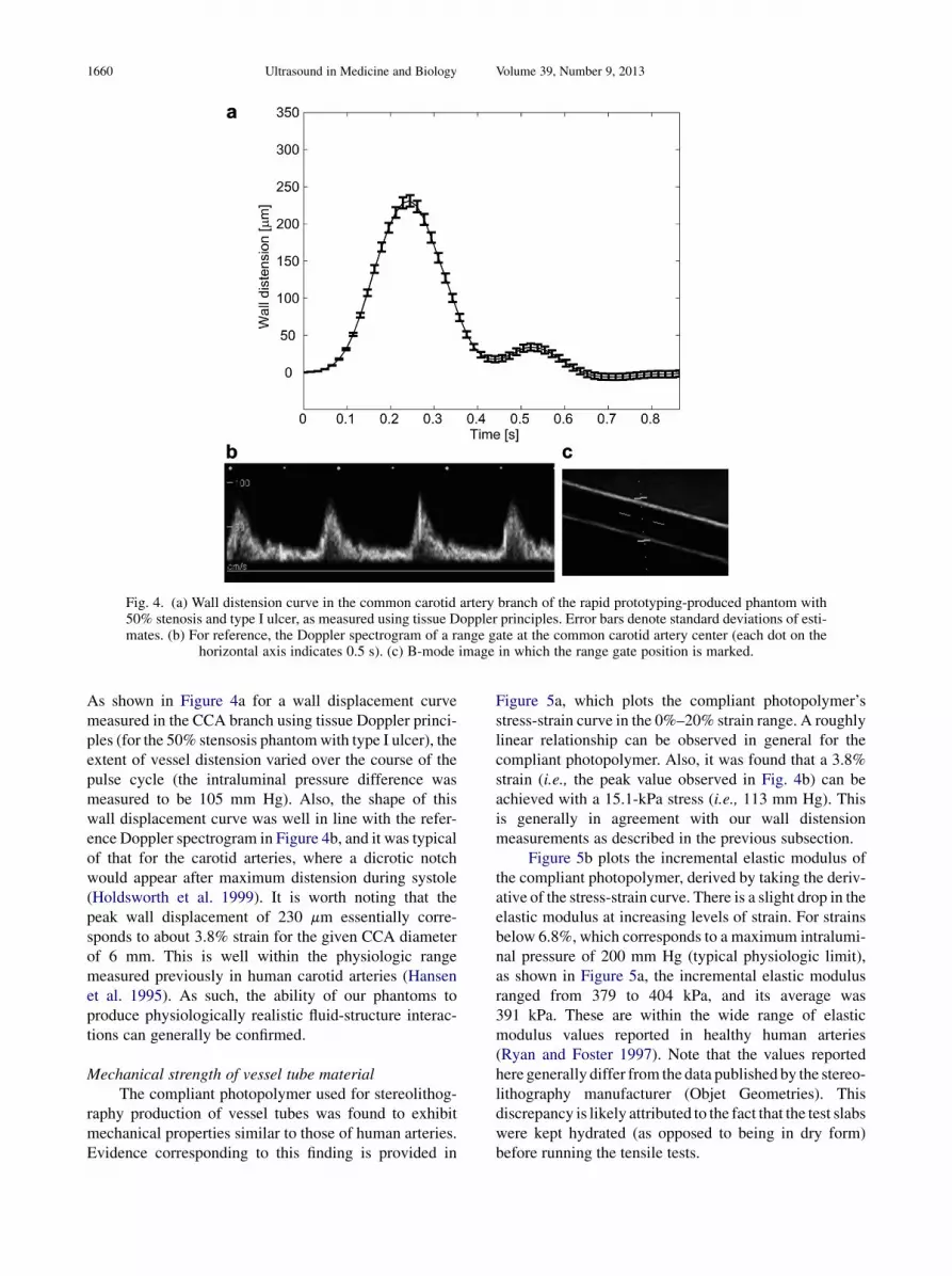
Fig. 4. (a) Wall distension curve in the common carotid artery branch of the rapid prototyping-produced phantom with50% stenosis and type I ulcer, as measured using tissue Doppler principles. Error bars denote standard deviations of esti-mates. (b) For reference, the Doppler spectrogram of a range gate at the common carotid artery center (each dot on the
horizontal axis indicates 0.5 s). (c) B-mode image in which the range gate position is marked.
1660 Ultrasound in Medicine and Biology Volume 39, Number 9, 2013
As shown in Figure 4a for a wall displacement curvemeasured in the CCA branch using tissue Doppler princi-ples (for the 50% stensosis phantomwith type I ulcer), theextent of vessel distension varied over the course of thepulse cycle (the intraluminal pressure difference wasmeasured to be 105 mm Hg). Also, the shape of thiswall displacement curve was well in line with the refer-ence Doppler spectrogram in Figure 4b, and it was typicalof that for the carotid arteries, where a dicrotic notchwould appear after maximum distension during systole(Holdsworth et al. 1999). It is worth noting that thepeak wall displacement of 230 mm essentially corre-sponds to about 3.8% strain for the given CCA diameterof 6 mm. This is well within the physiologic rangemeasured previously in human carotid arteries (Hansenet al. 1995). As such, the ability of our phantoms toproduce physiologically realistic fluid-structure interac-tions can generally be confirmed.
Mechanical strength of vessel tube materialThe compliant photopolymer used for stereolithog-
raphy production of vessel tubes was found to exhibitmechanical properties similar to those of human arteries.Evidence corresponding to this finding is provided in
Figure 5a, which plots the compliant photopolymer’sstress-strain curve in the 0%–20% strain range. A roughlylinear relationship can be observed in general for thecompliant photopolymer. Also, it was found that a 3.8%strain (i.e., the peak value observed in Fig. 4b) can beachieved with a 15.1-kPa stress (i.e., 113 mm Hg). Thisis generally in agreement with our wall distensionmeasurements as described in the previous subsection.
Figure 5b plots the incremental elastic modulus ofthe compliant photopolymer, derived by taking the deriv-ative of the stress-strain curve. There is a slight drop in theelastic modulus at increasing levels of strain. For strainsbelow 6.8%, which corresponds to a maximum intralumi-nal pressure of 200 mm Hg (typical physiologic limit),as shown in Figure 5a, the incremental elastic modulusranged from 379 to 404 kPa, and its average was391 kPa. These are within the wide range of elasticmodulus values reported in healthy human arteries(Ryan and Foster 1997). Note that the values reportedhere generally differ from the data published by the stereo-lithography manufacturer (Objet Geometries). Thisdiscrepancy is likely attributed to the fact that the test slabswere kept hydrated (as opposed to being in dry form)before running the tensile tests.

Fig. 5. Mechanical property measurements of compliant photopolymer used for vessel tube production. (a) Averagestress-strain curve for the strain range 0%–20%. (b) Elastic modulus as derived from the slope of stress-strain curves.
The test slabs were kept hydrated when making these measurements.
Anthropomorphic flow phantoms with compliant vessels d S. S. M. LAI et al. 1661
Acoustic properties of phantom materialsThe acoustic properties of the compliant photo-
polymer used for vessel tube fabrication are listed inTable 1. The average speed of sound for this materialwas measured to be 1801 m/s. This is higher than thatfor human arteries, as nominal values between 1600and 1760 m/s have been reported for healthy and diseasedarteries (Hoskins 2007). On the other hand, the acousticspeed of the agar-based tissue-mimicking material wasfound to be 1555 m/s (see Table 1), and this is close tothe nominal value of 1540 m/s for human tissues.
In terms of acoustic attenuation, the compliantphotopolymer was found to exhibit strong signal suppres-sion characteristics. As shown in Figure 6a, at 5-MHzultrasound frequency, there is a signal drop of 7.5 dB/mm for this photopolymer. It significantly contrastswith the tissue-mimicking material, whose attenuationis only 0.07 dB/mm at the same ultrasound frequency(see Fig. 6b). By fitting these measurements to thepower-law relationship a 5 ao fn, we determined thecompliant photopolymer’s attenuation coefficient, ao, tobe 1.58 dB/mm$MHzn (see Table 1), and its power coef-
Table 1. Acoustic properties of our phantoms’ tissue-mimicking material and vessel tube material
ParameterTissue-mimicking
materialVessel tubematerial
Acoustic speed, co (m/s) 1555 6 0.6* 1802 6 6.0Attenuation coefficient,ao [dB/(mm$MHzn)]
0.0179 6 0.002 1.580 6 0.035
Power-law dependenceof attenuation, n
0.87 6 0.03 0.97 6 0.02
* Mean 6 standard deviation.
ficient n was estimated to be 0.97. Such an attenuationlevel is close to the range for atherosclerotic arteries(Hoskins 2007), but it is significantly higher than theaverage value of 0.0179 dB/mm$MHzn (with n 5 0.87)for the tissue-mimicking material. This represents a limi-tation of using our design framework for developing flowphantoms. Fortunately, because the vessel tubes are typi-cally very thin (less than 1 mm thick), the impact of thisattenuation can be kept in check. For instance, as shownin the color flow images of Figure 3, it is still possible tovisualize the flow pattern and the vessel walls of an entirevessel branch.
DISCUSSION
Main contribution: A new rapid prototyping approachto flow phantom design
Fabrication of anatomically realistic flow phantomsfor vascular ultrasound studies is well recognized asa non-trivial task (Hoskins 2008). Whilst researchershave previously used excised arteries as a solution(Dabrowski et al. 2001), such an approach after all lacksexperimental flexibility and repeatability, as the vascularanatomy cannot be readily manipulated to foster system-atic analysis of the impact of different pathologicalfactors on ultrasound-based flow measurements (thereare also ethical concerns over the excision of arteries).In addressing this issue, we have made engineering inno-vations in which a new design framework for anthropo-morphic flow phantoms has been formulated on thebasis of RP technologies. Specifically, we have deter-mined that, with the use of compliant photopolymers aswall material, stereolithography can be used to consis-tently produce elastic vessel tubes with thin walls (0.8

Fig. 6. Acoustic attenuation measurements of (a) vessel tube material and (b) tissue-mimicking material. Results are ex-pressed in units of decibels per millimeter for the frequency range 2–5 MHz. Each marker indicates the measurement for
one test slab at one frequency. Th regression line is shown to illustrate the frequency dependence trend.
1662 Ultrasound in Medicine and Biology Volume 39, Number 9, 2013
mm in our case) and arbitrary geometries (stenotic and ul-cerated carotid bifurcation models were considered inthis work). By coupling these vessel tubes with an agar-based tissue-mimicking material and connecting themto a pulsatile pump, anthropomorphic flow phantomscan be readily produced to serve as experimental flowdevices for ultrasound investigations.
Perhaps one key advantage of our RP-basedphantom design framework is that it does not requirethe use of investment casting in fabricating the vesseltubes. This significantly reduces the difficulty ofproducing complex vessel geometries, as investmentcasting is known to be technically arduous and requiresa long development time (it is a multi-step processinvolving the sequential generation of master pattern,negative mold and vessel replica). Another technicaladvantage of our new phantom design framework isthat, given the flexibility in drafting arbitrary vesselgeometries using software and subsequently printingthem using stereolithography, we can readily pursue thefabrication of even more sophisticated vessel tubes suchas ones with vessel curvatures, multiple side branchesand aneurysms. These are deemed to be difficult to realizeusing investment casting because non-planar vesselgeometries would drastically make it more challengingto form negative molds (Wong et al. 2008). As such,our new framework may provide opportunities in system-atically conducting ultrasound-based experimental inves-tigations of highly complex flow settings. It may also beleveraged to develop patient-specific flow phantoms thatare transcribed from a real subject’s vascular anatomy asobtainable from magnetic resonance imaging, computedtomography or B-mode ultrasound scans. This shouldbenefit application development efforts in 3-D ultrasound
flow imaging, the real-time feasibility of which has beendetermined with recent advances in two-dimensionalarray transducer design (Karadayi et al. 2009).
Compatibility of compliant photopolymer as a vesselwall material
In terms of the suitability of compliant photo-polymer as a vessel tube material, our mechanical charac-terization results indicate that its elastic modulus issimilar to those reported for human arteries. Neverthe-less, its acoustic properties are sub-optimal, with theacoustic speed and attenuation coefficient both beinghigher than those of normal tissues and blood. Fortu-nately, because walls thinner than 1 mmmay be producedusing stereolithography, the impact of this acousticmismatch should be kept in check. In fact, we have shownthat the Doppler spectrogram profiles and color flowimages obtained from phantoms with diseased geome-tries closely resemble what is expected of disturbedflow, thereby suggesting that the non-ideal acoustic prop-erties of our RP-produced vessels have limited impact onthe detected flow profile.
The acoustic mismatch of the compliant photo-polymer would likely become a more significant issuein cases where thicker walls are required, such as whendesigning cardiac phantoms (Lesniak-Plewinska et al.2010). In these cases, the photopolymer’s higher-than-normal acoustic speed is expected to give rise to signifi-cant wall refraction artifacts that distort the flow signals(Steel and Fish 2003). Also, its high acoustic attenuationwould undoubtedly reduce the flow signal quality,thereby increasing the challenge of detecting slow flownear the wall by clinical ultrasound scanners (Browneet al. 2004). As such, in developing thick-walled

Anthropomorphic flow phantoms with compliant vessels d S. S. M. LAI et al. 1663
phantoms, it may be necessary to use an alternate wallmaterial like polyvinyl alcohol cryogel (Dingley et al.2006; King et al. 2011), whose acoustic and mechanicalproperties may both be tuned by adjusting the numberof freeze-thaw cycles. Nevertheless, the fabricationprocess would be inherently more labor intensive.
CONCLUSION
As the role of flow phantoms expands beyond theirtraditional function as calibration devices for ultrasoundscanners, there is an increasing motivation to developanthropomorphic phantoms with authentic arterial geom-etry and close resemblance to in vivo flow dynamics. Inthis work, using carotid bifurcation models as an illustra-tion, we established how a range of anthropomorphic flowphantoms with different pathologic features may be effi-ciently developed by leveraging on stereolithographytechnologies (one form of RP) to directly fabricatecomplex vessel models constructed in computer-aideddesign software. Our new design framework may bereadily applied to develop phantoms for other vascularsystems and, in turn, provide essential experimental toolsfor pursuing innovations in Doppler ultrasound measure-ments in those parts of the vasculature. Phantomsproduced from this framework may also serve asin vitro testbeds for fostering the development of newultrasound-based flow imaging paradigms. These investi-gative tools may therefore help to strengthen applicationdevelopment efforts in vascular ultrasound and to validatethe feasibility of new ways of imaging blood flow, espe-cially for cases with significant flow disturbance (oreven turbulence).
Acknowledgments—The authors are grateful to Dr. K. W. Chan,Mr. Frank Tse andMr. Ringo Liu for their helpful advice on stereolithog-raphy and tensile testing. This work is funded in part by the ResearchGrants Council of Hong Kong (GRF 785811 M) and the Hong KongInnovation and Technology Fund (ITS/083/11).
REFERENCES
Berselli G, Vertechy R, Pellicciari M, Vassura G. Hyperelastic modelingof rubber-like photopolymers for additive manufacturing processes.In: Hoque ME, (ed). Rapid prototyping technology—Principles andfunctional requirements. Rijeka: InTech; 2011. p. 135–152.
Browne JE, Watson AJ, Hoskins PR, Elliott AT. Validation of a sensi-tivity performance index test protocol and evaluation of colourDoppler sensitivity for a range of ultrasound scanners. UltrasoundMed Biol 2004;30:1475–1483.
DabrowskiW, Dunmore-Buyze J, Cardinal HN, Fenster A. A real vesselphantom for flow imaging: 3-D Doppler ultrasound of steady flow.Ultrasound Med Biol 2001;27:135–141.
Dingley J, Meagher S, Poepping TL, McDicken WN, Hoskins PR.Design and characterization of a wall motion phantom. UltrasoundMed Biol 2006;32:1349–1357.
Dubiel M, Hammid A, Breborowicz A, Pietryga M, Sladkevicius P,Olofsson PA, Breborowicz GH, Gudmundsson S. Flow index evalu-ation of 3-D volume flow images: An in vivo and in vitro study.Ultrasound Med Biol 2006;32:665–671.
Evans DE, McDicken WN. Doppler Ultrasound: Physics, Instrumenta-tion and Signal Processing. 2nd ed. New York: Wiley; 2000.
Grant EG, Benson CB,Moneta GL, Alexandrov AV, Baker JD, Bluth EI,Carroll BA, Eliasziw M, Gocke J, Hertzberg BS, Katanick S,Needleman L, Pellerito J, Polak JF, Rholl KS, Wooster DL,Zierler E. Carotid artery stenosis: Ggray-scale and Doppler USdiagnosis—Society of Radiologists in Ultrasound ConsensusConference. Radiology 2003;229:340–346.
Hansen F, Mangell P, Sonesson B, Lanne T. Diameter and compliance inthe human common carotid artery—Variations with age and sex.Ultrasound Med Biol 1995;21:1–9.
Holdsworth DW, Norley CJD, Frayne R, Steinman DA, Rutt BK. Char-acterization of common carotid artery blood-flow waveforms innormal human subjects. Physiol Meas 1999;20:219–240.
Hoskins PR. Physical properties of tissues relevant to arterial ultrasoundimaging and blood velocity measurement. Ultrasound Med Biol2007;33:1527–1539.
Hoskins PR. Simulation and validation of arterial ultrasound imagingand blood flow. Ultrasound Med Biol 2008;34:693–717.
Karayadi K, Managuli R, Kim Y. Three-dimensional ultrasound: Fromacquisition to visualization and from algorithms to systems. IEEERev Biomed Eng 2009;2:23–39.
King DM, Moran CM, McNamara JD, Fagan AJ, Browne JE. Develop-ment of a vessel-mimicking material for use in anatomically realisticDoppler flow phantoms. Ultrasound Med Biol 2011;37:813–826.
King DM, Ring M, Moran CM, Browne JE. Development of a range ofanatomically realistic renal artery flow phantoms. Ultrasound MedBiol 2010;36:1135–1144.
Krejza J, Arkuszewski M, Kasner SE, Weigele J, Ustymowicz A,Hurst RW, Cucchiara BL, Messe SR. Carotid artery diameter inmen and women and the relation to body and neck size. Stroke2006;37:1103–1105.
Lantada AD, Morgado PL. Rapid prototyping for biomedical engi-neering: Current capabilities and challenges. Annu Rev BiomedEng 2012;14:73–96.
Lesniak-Plewinska B, Cygan S, Kaluzynski K, D’hooge J,Zmigrodzki J, Kowalk E, Kordybach M, Kowalski M. A dual-chamber, thick-walled cardiac phantom for use in cardiac motionand deformation imaging by ultrasound. Ultrasound Med Biol2010;36:1145–1156.
Lovett JK, Rothwell PM. Site of carotid plaque ulceration in relation todirection of blood flow: An angiographic and pathological study.Cerebrovasc Dis 2003;16:369–375.
Lovett JK, Gallagher PJ, Hands LJ,Walton J, Rothwell PM. Histologicalcorrelates of carotid plaque surface morphology on lumen contrastimaging. Circulation 2004;110:2190–2197.
Lui EYL, Steinman AH, Cobbold RSC, Johnston KW. Human factors asa source of error in peak Doppler velocity measurement. J Vasc Surg2005;42:972–979.
Marinozzi F, Branca FP, Bini F, Scorza A. Calibration procedure forperformance evaluation of clinical pulsed Doppler systems.Measurement 2012;45:1334–1342.
Meagher S, Poepping TL, Ramnarine KV, Black RA, Hoskins PR.Anatomical flow phantoms of the nonplanar carotid bifurcation:Part II. Experimental validation with Doppler ultrasound. Ultra-sound Med Biol 2007;33:303–310.
O’Flynn PM, Roche ET, Pandit AS. Generating an ex vivo vascularmodel. Am Soc Artif Intern Org J 2005;51:426–433.
Poepping TL, Nikolov HN, Rankin RN, Lee M, Holdsworth DW. Anin vitro system for Doppler ultrasound flow studies in thestenosed carotid artery bifurcation. Ultrasound Med Biol 2002;28:495–506.
Poepping TL, Nikolov HN, ThorneML, Holdsworth DW. A thin-walledcarotid vessel phantom for Doppler ultrasound flow studies. Ultra-sound Med Biol 2004;30:1067–1078.
Poepping TL, Rankin RN, Holdsworth DW. Flow patterns in carotidbifurcation models using pulsed Doppler ultrasound: Effect ofconcentric vs. eccentric stenosis on turbulence and recirculation.Ultrasound Med Biol 2010;36:1125–1134.
Ramnarine KV, Nassiri DK, Hoskins PR, Lubbers J. Validation of a newblood-mimicking fluid for use in Doppler flow test objects. Ultra-sound Med Biol 1998;24:451–459.

1664 Ultrasound in Medicine and Biology Volume 39, Number 9, 2013
Ramnarine KV, Anderson T, Hoskins PR. Construction and geometricstability of physiological flow rate wall-less stenosis phantoms.Ultrasound Med Biol 2001;27:245–250.
Raine-Fenning NJ, Nordin NM, Ramnarine KV, Campbell BK,Clewes JS, Perkins A, Johnson IR. Determining the relationshipbetween three-dimensional power Doppler data and true bloodflow characteristics: An in-vitro flow phantom experiment. Ultra-sound Obstet Gynecol 2008a;32:540–550.
Raine-Fenning NJ, Nordin NM, Ramnarine KV, Campbell BK,Clewes JS, Perkins A, Johnson IR. Evaluation of the effect ofmachine settings on quantitative three-dimensional power Dopplerangiography: An in-vitro flow phantom experiment. Ultrasound Ob-stet Gynecol 2008b;32:551–559.
Rengier F, Mehndiratta A, von Tengg-Kobligh H, Zechmann CM,Unterhinninghofen R, Kauczor HU, Giesel FL. 3D printing basedon imaging data: Review of medical applications. Int J ComputAssist Radiol Surg 2010;5:335–341.
Ryan LK, Foster FS. Tissue equivalent vessel phantoms for intravascularultrasound. Ultrasound Med Biol 1997;23:261–273.
Smith RF, Rutt BK, Fox AJ, Rankin RN, Holdsworth DW. Geometriccharacterization of stenosed human carotid arteries. Acad Radiol1996;3:898–911.
SmithRF,RuttBK,HoldsworthDW.Anthropomorphiccarotid bifurcationphantom for MRI applications. J Mag Res Imag 1999;10:533–544.
Steel R, Fish PJ. A simulation study of sample volume sensitivity of ob-lique pulsed finite beam insonation of Doppler ultrasound flow
phantoms cylindrical vessels. IEEE Trans Ultrason FerroelectrFreq Control 2003;50:58–67.
Steinman AH, Tavakkoli J, Myers JG, Cobbold RSC, Johnston KW.Sources of error in maximum velocity estimation using linearphased array Doppler systems with steady flow. Ultrasound MedBiol 2001;27:655–664.
Steinman AH, Yu ACH, Johnston KW, Cobbold RSC. Effects of beamsteering in pulsed-wave ultrasound velocity estimation. UltrasoundMed Biol 2005;31:1073–1082.
Watts DM, Sutcliffe CJ, Morgan RH,Meagher S,Wardlaw J, ConnellM,Bastin ME, Marshall I, Ramnarine KV, Hoskins PR, Black RA.Anatomical flow phantoms of the nonplanar carotid bifurcation:Part I. Computer-aided design and fabrication. Ultrasound MedBiol 2007;33:296–302.
Wong EY, Nikolov HN, Thorne ML, Poepping TL, Rankin RN,Holdsworth DW. Clinical Doppler ultrasound for the assessmentof plaque ulceration in the stenosed carotid bifurcation by detectionof distal turbulence intensity: A matched model study. Eur Radiol2009;19:2739–2749.
Wong EY, Thorne ML, Nikolov HN, Poepping TL, Holdsworth DW.Doppler ultrasound compatible plastic material for use in rigidflow models. Ultrasound Med Biol 2008;34:1846–1856.
Zell K, Sperl JI, Vogel MW, Niessner R, Haisch C. Acoustical propertiesof selected tissue phantom materials for ultrasound imaging. PhysMed Biol 2007;52:N475–N484.