213465.pdf - enlighten: publications
TRANSCRIPT

Hwang, J., Ejsmont, A., Freund, R., Goscianska, J., Schmidt, B. V.K.J. and Wuttke, S. (2020) Controlling the morphology of metal–organic frameworks and porous carbon materials: metal oxides as primary architecture-directing agents. Chemical Society Reviews, 49(11), pp. 3348-3422.
There may be differences between this version and the published version. You are advised to consult the publisher’s version if you wish to cite from it.
http://eprints.gla.ac.uk/213465/
Deposited on: 16 April 2020
Enlighten – Research publications by members of the University of Glasgow http://eprints.gla.ac.uk
1
Controlling morphology of metal-organic frameworks and porous carbon 1
materials: metal oxides as primary architecture-directing agents 2
3
Jongkook Hwang,1 Aleksander Ejsmont,2 Ralph Freund,3 Joanna Goscianska,2,* Bernhard V. K. J. 4 Schmidt,4,*and Stefan Wuttke5,6,* 5
6
1Inorganic Chemistry and Catalysis, Utrecht University, Universiteitsweg 99, 3584 CG, Utrecht, 7 Netherlands 8
2Adam Mickiewicz University in Poznań, Faculty of Chemistry, Uniwersytetu Poznańskiego 8, 61-614 9 Poznań, Poland 10
3Chair of Solid State and Materials Chemistry, Institute of Physics, University of Augsburg, 11 Universitätsstraße 1, 86159 Augsburg, Germany 12
4School of Chemistry, Joseph Black Building, University of Glasgow, G128QQ, UK 13
5BCMaterials, Basque Center for Materials, UPV/EHU Science Park, 48940 Leioa, Spain 14
6Ikerbasque, Basque Foundation for Science, 48013, Bilbao, Spain 15 16
*Correspondence to: [email protected]; [email protected]; 17 [email protected] 18
19
Abstract 20
Owing to their vast ratio of surface area to mass and volume, metal-organic frameworks and porous 21 carbons revolutionized many applications that rely on chemical and physical interactions at surfaces. 22 However, a major challenge today is to shape these porous materials to translate their enhanced 23 performance from the laboratory into macroscopic real-world applications. In this review, we give a 24 comprehensive overview of how the precise morphology control of metal oxides can be transferred 25 to metal-organic framework and porous carbon materials. As such, tailored material structures can 26 be designed in 0D, 1D, 2D, and 3D with considerable implications for applications like energy storage, 27 catalysis or nanomedicine. Therefore, we predict that major research advances in morphology 28 control of metal-organic frameworks and porous carbons will facilitate the use of those materials in 29 addressing major needs of the society, especially the grand challenges of energy, health, and 30 environment. 31
32
2
1. Introduction 1
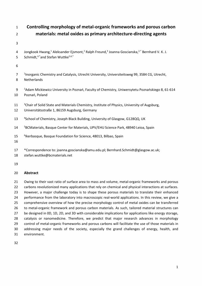
Porous materials are of high interest for diverse applications ranging from catalysis and separation to 2 gas storage and sensing. These materials can interact with their surrounding not only on their 3 external surface, but throughout the vast internal surface of the pores. By functionalizing the internal 4 and/or external surface, the activity can be tailored to the application. However, a great challenge 5 today is to build materials that translate the functionality at the molecular level effectively to the 6 macroscopic world. To do this, effective transport of reagents to, from, and within porous materials 7 is critical. To overcome this barrier, porous materials will need to be structured with feature sizes 8 from below one micrometre to the millimetre or centimetre scale. In fact, the challenge of 9 morphology control over multiple length scales (Fig. 1) of porous materials is overlooked by 10 researchers so far but is the key to enable groundbreaking real-world applications. 11
12
Fig. 1. Illustrating the challenge to synthesise a macroscopic object (e.g. toy frog, right) with the 13 same morphology at the mesoscale (light microscope image, middle) and at the nanoscale (scanning 14 electron microscopy image, left). 15
Recent years have seen a surge in work on materials that are based on reticular chemistry.1-8 In 16 reticular chemistry, molecular building blocks with controlled shape, geometry, functionality and 17 valence are connected with strong chemical bonds to form porous, crystalline framework structures. 18 Organic building blocks can then be assembled with secondary building units (SBU, e.g. metal-oxo 19 clusters) to form extended materials called metal-organic frameworks (MOFs). The nodes and 20 vertices of reticular materials are designed in such a way that they are rigid and directional, which is 21 of great importance as it enables structure prediction and design. The rigidity and directionality of 22 the components also make these materials porous, as free voids in the materials are easily created. 23 These free voids can be post-synthetically modified to add different functionality to the material.6, 8, 9 24 The accessibility of the interior of these materials to guests, in addition to the design and 25 functionality aspect, has led to tremendous interest in reticular materials as they are inherently 26 useful for gas adsorption, catalysis, sensing, and drug delivery.6-8, 10 However, the morphology control 27 of MOF materials beyond their periodic and designed networks is the current key challenge that has 28 to be addressed in order to translate the scientific innovation of reticular chemistry from the lab 29 bench into applicable technologies.11 30
The synthesis of a MOF material always starts with the strategic selection of precursor materials. 31 Besides an organic building block, an inorganic compound providing metal ions is necessary, which 32 most commonly is a metal salt, as it easily dissolves. A relatively new and different approach is the 33 use of metal oxides (MOs). Even though their use is challenging due to low solubility issues and slow 34 and non-homogenous conversion, by carefully optimizing the experimental conditions the MO–to–35 MOF conversion can be carried out with preserving the morphology of the MO. Thus, the use of MO 36
3
precursors, which offers a huge number of different morphologies that can be synthesized with high 1 precision, potentially provides an easy and smart way for the precise synthesis of different MOF 2 morphologies. This strategy opens the door to morphologies that cannot be achieved using reactions 3 based on metal salt precursors or other approaches. 4
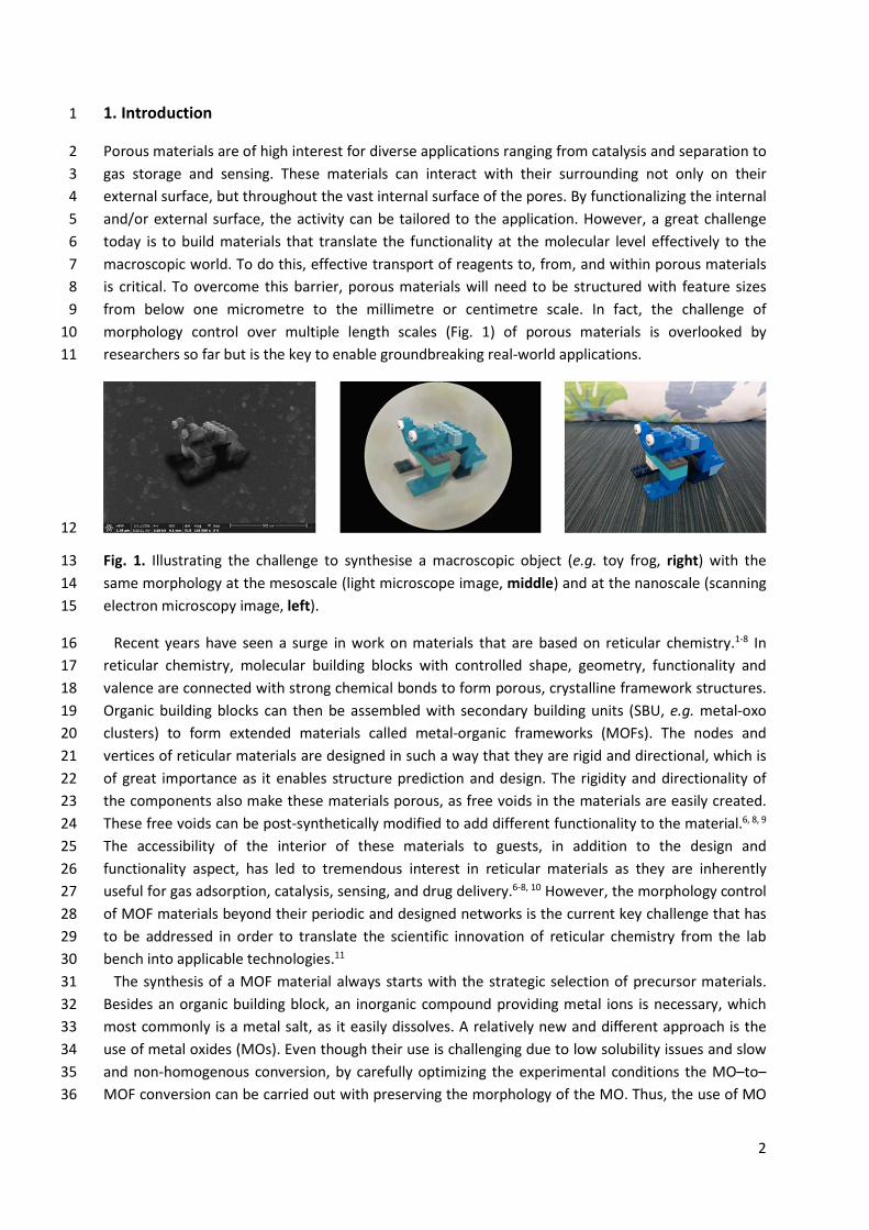
Moreover, the careful carbonization of those MOF materials offers to translate this morphology 5 control to porous carbon.12, 13 MOF materials could be used as “all-in-one” templates/precursors that 6 contain both inorganic and organic constituents which can be pre-selected for preparation of 7 targeted porous carbon materials, so called MOF-derived carbon (MDC), with specific morphologies 8 and a plethora of applications, e.g. in energy storage, catalysis or nanomedicine.14 MO, MOF and 9 MDC are closely connected, which facilitates synthetic avenues from MO over MOF to MDC with 10 control over morphology from the first building blocks to the final carbon material (Fig. 2). As such, 11 control over MO morphology allows architecture direction over the whole synthesis route. This 12 approach enables additional control over morphology and access to complex material architectures 13 that are challenging to achieve via MOFs alone. 14
In this review, we summarize the morphology control methods of MOF/MDC with particular 15 emphasis on the use of “MO as primary architecture directing agents”. Starting from morphology 16 control of MO itself, we cover the transformation of MO into MOF and finally into MDC. To do so, we 17 categorize the reported MO/MOF/MDC products according to their synthetic strategies and particle 18 morphologies (0D, 1D, 2D, 3D and hierarchical architectures). The synthetic methods, mechanisms, 19 and their advantages and limitations are discussed comprehensively. Morphology controlled MOF 20 and MDC materials have shown already great potential in a number of applications such as batteries, 21 supercapacitors, fuel cells, adsorption, catalysis, sensing, and nanomedicine, which will be addressed 22 as well. Overall, the review describes the avenue from MO over MOF to obtain well-defined MDC for 23 applications. 24
25
Fig. 2. Outline the article that follows the synthetic avenue from morphology-controlled metal 26 oxides, transformation to MOFs, carbonization, applications and perspectives. 27
4
2. Morphology 1
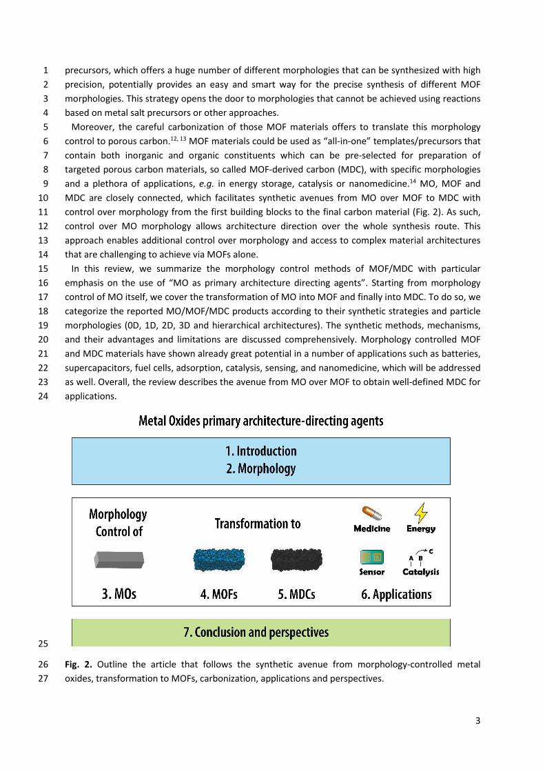
According to the International Union of Pure and Applied Chemistry (IUPAC), morphology is defined 2 as shape, optical appearance, texture or topography of surface and form of phase domains in 3 materials. The expressions morphology and shape are usually used as synonyms when describing the 4 external structure of nanoparticles and their aggregates.15, 16 However, the differences between 5 these concepts should be emphasized. The term morphology includes physical size, flatness, 6 roundness, sphericity and aspect ratio of the nanoparticles while the shape considers their 7 appearance without taking into account specific dimensions (Fig. 3). 8
9 Fig. 3. Top: morphology in form of 3D particles (left: smooth surface, middle: roughly nanostructure 10 surface, right: smooth surface), bottom: shape in form of 2D projection (left, middle: spherical, right: 11 square). 12 13
The concept of morphology may seem intuitive until one attempts to determine the appropriate 14 classification system of particles with regular and irregular shapes employing advanced 2D and 3D 15 microscopy imaging techniques.17, 18 This system of classification should be as versatile as possible 16 and apply to a wide range of materials. In the case of nanostructures, the greatest difficulty in 17 describing their morphology is that they undergo continuous transformations from one form to 18 another. However, in 1995, Gleiter19 presented the first classification system of nanostructured 19 materials that was explained in detail by Skorohod et al.20 It was incomplete because it did not 20 include zero-dimensional (0D), one-dimensional (1D), two-dimensional (2D) and three-dimensional 21 (3D) nanostructures e.g. fullerenes, tubes, and flowers. Thus, Pokropivny and Skorokhod21 developed 22 a modified classification system, in which they took into account the above-mentioned 23 nanostructures. Nanomaterials were classified as 0D, 1D, 2D, 3D depending on their specific 24 geometrical dimensions. Fig. 4 shows a schematic representation of various nanostructures and plots 25 of energy dependence versus density of states.22 It was found that the degree of confinement 26 determines electronic density of state for different types of nanostructures. 27 28
5
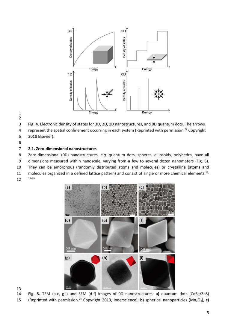
1 2 Fig. 4. Electronic density of states for 3D, 2D, 1D nanostructures, and 0D quantum dots. The arrows 3 represent the spatial confinement occurring in each system (Reprinted with permission.22 Copyright 4 2018 Elsevier). 5
6 2.1. Zero-dimensional nanostructures 7 Zero-dimensional (0D) nanostructures, e.g. quantum dots, spheres, ellipsoids, polyhedra, have all 8 dimensions measured within nanoscale, varying from a few to several dozen nanometers (Fig. 5). 9 They can be amorphous (randomly distributed atoms and molecules) or crystalline (atoms and 10 molecules organized in a defined lattice pattern) and consist of single or more chemical elements.18, 11 22-29 12
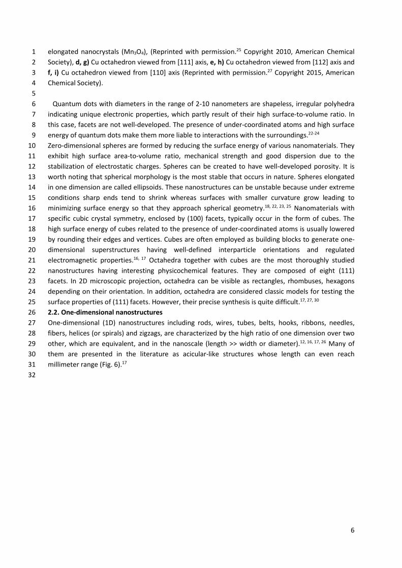
13 Fig. 5. TEM (a-c, g-i) and SEM (d-f) images of 0D nanostructures: a) quantum dots (CdSe/ZnS) 14 (Reprinted with permission.24 Copyright 2013, Inderscience), b) spherical nanoparticles (Mn3O4), c) 15
6
elongated nanocrystals (Mn3O4), (Reprinted with permission.25 Copyright 2010, American Chemical 1 Society), d, g) Cu octahedron viewed from [111] axis, e, h) Cu octahedron viewed from [112] axis and 2 f, i) Cu octahedron viewed from [110] axis (Reprinted with permission.27 Copyright 2015, American 3 Chemical Society). 4 5
Quantum dots with diameters in the range of 2-10 nanometers are shapeless, irregular polyhedra 6 indicating unique electronic properties, which partly result of their high surface-to-volume ratio. In 7 this case, facets are not well-developed. The presence of under-coordinated atoms and high surface 8 energy of quantum dots make them more liable to interactions with the surroundings.22-24 9 Zero-dimensional spheres are formed by reducing the surface energy of various nanomaterials. They 10 exhibit high surface area-to-volume ratio, mechanical strength and good dispersion due to the 11 stabilization of electrostatic charges. Spheres can be created to have well-developed porosity. It is 12 worth noting that spherical morphology is the most stable that occurs in nature. Spheres elongated 13 in one dimension are called ellipsoids. These nanostructures can be unstable because under extreme 14 conditions sharp ends tend to shrink whereas surfaces with smaller curvature grow leading to 15 minimizing surface energy so that they approach spherical geometry.18, 22, 23, 25 Nanomaterials with 16 specific cubic crystal symmetry, enclosed by (100) facets, typically occur in the form of cubes. The 17 high surface energy of cubes related to the presence of under-coordinated atoms is usually lowered 18 by rounding their edges and vertices. Cubes are often employed as building blocks to generate one-19 dimensional superstructures having well-defined interparticle orientations and regulated 20 electromagnetic properties.16, 17 Octahedra together with cubes are the most thoroughly studied 21 nanostructures having interesting physicochemical features. They are composed of eight (111) 22 facets. In 2D microscopic projection, octahedra can be visible as rectangles, rhombuses, hexagons 23 depending on their orientation. In addition, octahedra are considered classic models for testing the 24 surface properties of (111) facets. However, their precise synthesis is quite difficult.17, 27, 30 25 2.2. One-dimensional nanostructures 26 One-dimensional (1D) nanostructures including rods, wires, tubes, belts, hooks, ribbons, needles, 27 fibers, helices (or spirals) and zigzags, are characterized by the high ratio of one dimension over two 28 other, which are equivalent, and in the nanoscale (length >> width or diameter).12, 16, 17, 26 Many of 29 them are presented in the literature as acicular-like structures whose length can even reach 30 millimeter range (Fig. 6).17 31 32
7
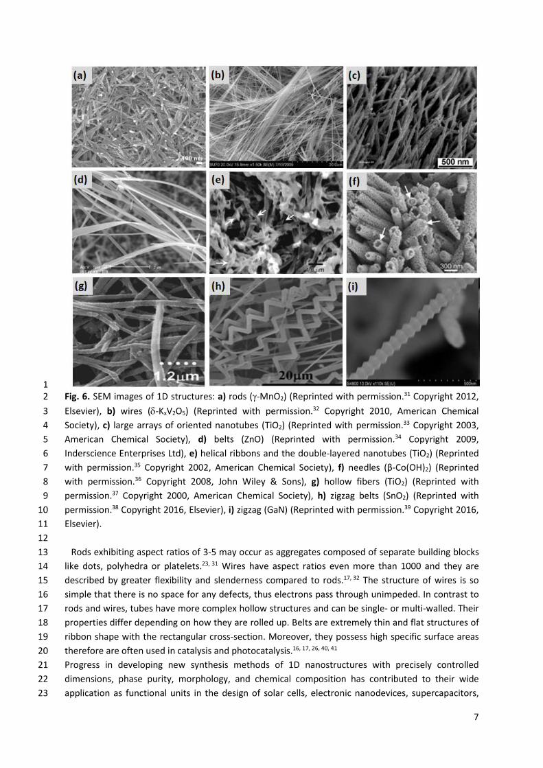
1 Fig. 6. SEM images of 1D structures: a) rods (J-MnO2) (Reprinted with permission.31 Copyright 2012, 2 Elsevier), b) wires (G-KxV2O5) (Reprinted with permission.32 Copyright 2010, American Chemical 3 Society), c) large arrays of oriented nanotubes (TiO2) (Reprinted with permission.33 Copyright 2003, 4 American Chemical Society), d) belts (ZnO) (Reprinted with permission.34 Copyright 2009, 5 Inderscience Enterprises Ltd), e) helical ribbons and the double-layered nanotubes (TiO2) (Reprinted 6 with permission.35 Copyright 2002, American Chemical Society), f) needles (β-Co(OH)2) (Reprinted 7 with permission.36 Copyright 2008, John Wiley & Sons), g) hollow fibers (TiO2) (Reprinted with 8 permission.37 Copyright 2000, American Chemical Society), h) zigzag belts (SnO2) (Reprinted with 9 permission.38 Copyright 2016, Elsevier), i) zigzag (GaN) (Reprinted with permission.39 Copyright 2016, 10 Elsevier). 11 12
Rods exhibiting aspect ratios of 3-5 may occur as aggregates composed of separate building blocks 13 like dots, polyhedra or platelets.23, 31 Wires have aspect ratios even more than 1000 and they are 14 described by greater flexibility and slenderness compared to rods.17, 32 The structure of wires is so 15 simple that there is no space for any defects, thus electrons pass through unimpeded. In contrast to 16 rods and wires, tubes have more complex hollow structures and can be single- or multi-walled. Their 17 properties differ depending on how they are rolled up. Belts are extremely thin and flat structures of 18 ribbon shape with the rectangular cross-section. Moreover, they possess high specific surface areas 19 therefore are often used in catalysis and photocatalysis.16, 17, 26, 40, 41 20 Progress in developing new synthesis methods of 1D nanostructures with precisely controlled 21 dimensions, phase purity, morphology, and chemical composition has contributed to their wide 22 application as functional units in the design of solar cells, electronic nanodevices, supercapacitors, 23
8
gas sensors or transistors. Xia et al.34 have compiled bottom-up synthetic strategies for fabrication of 1 1D nanostructures which involve: (i) utilization of the intrinsically anisotropic crystallographic 2 structure of a solid to achieve 1D growth, (ii) reduction of the seed symmetry by introducing a liquid-3 solid interface, (iii) modification of seed growth by control of supersaturation, (iv) capping reagent 4 assisted procedure in order to kinetic control the growth rates of different facets of seeds, (v) 5 application of appropriate templates exhibited 1D morphologies to manage the 1D nanostructures 6 creation, (vi) 0D nanostructures self-assembly and (vii) reducing the size of 1D microstructures. It 7 should be noted that a wide variety of materials can naturally grow into 1D nanostructures which is 8 influenced by highly anisotropic bonding in crystallographic structures. They exhibit distinct optical, 9 thermal, chemical and electronic properties. In addition, 1D nanostructures are interesting systems 10 for studying new phenomena at the nanoscale and dependence of specific physicochemical 11 properties on the shape and dimensions.34 12
13 2.3. Two-dimensional nanostructures 14 Two-dimensional (2D) nanomaterials, possessing thickness in the range from a few to tens of 15 nanometers and lateral dimension reaching up to many centimeters, have been a subject of intensive 16 research in the last years.12, 16, 17, 26, 42 They are described in the literature as single- or multilayered 17 nanostructures with strong bonds in plane and weak van der Waals forces between layers which are 18 often deposited on the surface of various substrates (e.g. silicon, nickel sheets, copper foil). 2D 19 nanostructures typically include platelets, sheets, flakes, rings, membranes, walls, prisms, disks, films 20 characterized by unique geometry, well-developed surface area and high surface-to-volume ratio 21 (Fig. 7).12, 16, 17, 26, 42, 43 In addition, the advantages of 2D nanostructures are also the presence of many 22 active sites, straightforward surface functionalization and possibility to assembly into 3D complex 23 structures. Up to now, 2D nanostructures of graphene, metal oxides, polymers, metal hydroxides, 24 metal dichalcogenides, boron nitride, phosphorene, MXenes and metal organic frameworks have 25 been synthesized with the use of strategies based on extraction, exfoliation, chemical or physical 26 vapor deposition and various wet chemical methods.36 27 28
9
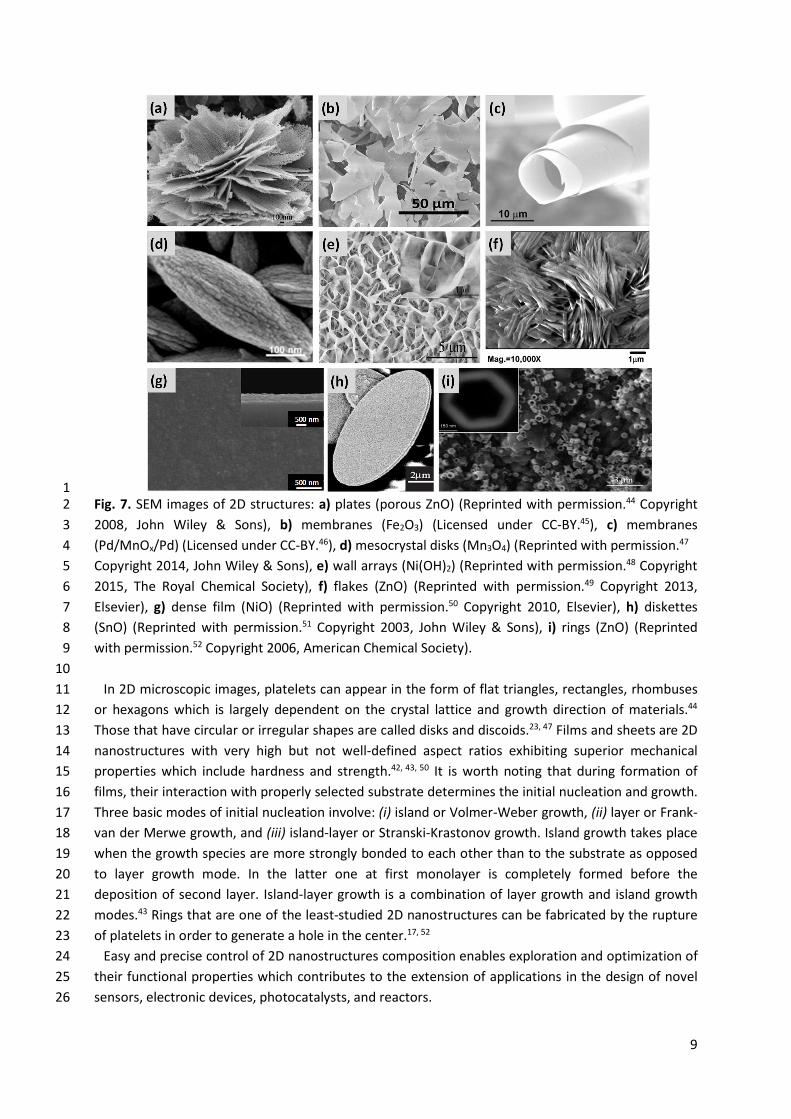
1 Fig. 7. SEM images of 2D structures: a) plates (porous ZnO) (Reprinted with permission.44 Copyright 2 2008, John Wiley & Sons), b) membranes (Fe2O3) (Licensed under CC-BY.45), c) membranes 3 (Pd/MnOx/Pd) (Licensed under CC-BY.46), d) mesocrystal disks (Mn3O4) (Reprinted with permission.47 4 Copyright 2014, John Wiley & Sons), e) wall arrays (Ni(OH)2) (Reprinted with permission.48 Copyright 5 2015, The Royal Chemical Society), f) flakes (ZnO) (Reprinted with permission.49 Copyright 2013, 6 Elsevier), g) dense film (NiO) (Reprinted with permission.50 Copyright 2010, Elsevier), h) diskettes 7 (SnO) (Reprinted with permission.51 Copyright 2003, John Wiley & Sons), i) rings (ZnO) (Reprinted 8 with permission.52 Copyright 2006, American Chemical Society). 9
10 In 2D microscopic images, platelets can appear in the form of flat triangles, rectangles, rhombuses 11
or hexagons which is largely dependent on the crystal lattice and growth direction of materials.44 12 Those that have circular or irregular shapes are called disks and discoids.23, 47 Films and sheets are 2D 13 nanostructures with very high but not well-defined aspect ratios exhibiting superior mechanical 14 properties which include hardness and strength.42, 43, 50 It is worth noting that during formation of 15 films, their interaction with properly selected substrate determines the initial nucleation and growth. 16 Three basic modes of initial nucleation involve: (i) island or Volmer-Weber growth, (ii) layer or Frank-17 van der Merwe growth, and (iii) island-layer or Stranski-Krastonov growth. Island growth takes place 18 when the growth species are more strongly bonded to each other than to the substrate as opposed 19 to layer growth mode. In the latter one at first monolayer is completely formed before the 20 deposition of second layer. Island-layer growth is a combination of layer growth and island growth 21 modes.43 Rings that are one of the least-studied 2D nanostructures can be fabricated by the rupture 22 of platelets in order to generate a hole in the center.17, 52 23
Easy and precise control of 2D nanostructures composition enables exploration and optimization of 24 their functional properties which contributes to the extension of applications in the design of novel 25 sensors, electronic devices, photocatalysts, and reactors. 26
10
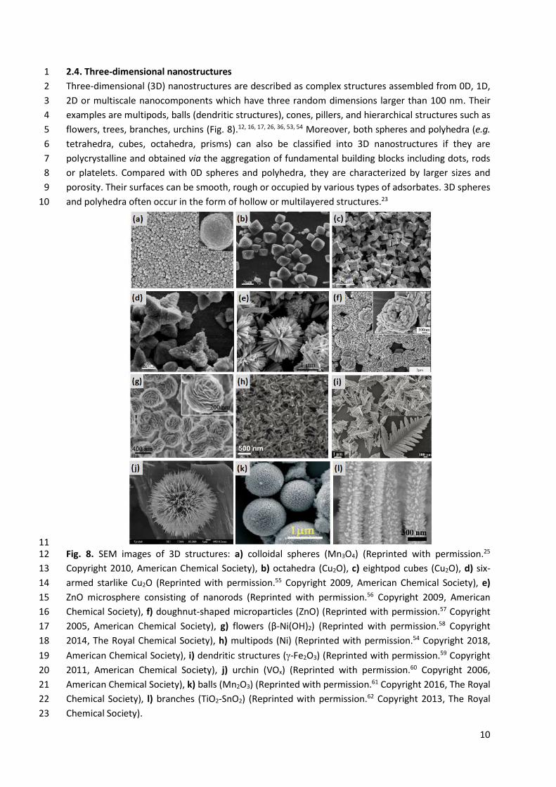
2.4. Three-dimensional nanostructures 1 Three-dimensional (3D) nanostructures are described as complex structures assembled from 0D, 1D, 2 2D or multiscale nanocomponents which have three random dimensions larger than 100 nm. Their 3 examples are multipods, balls (dendritic structures), cones, pillers, and hierarchical structures such as 4 flowers, trees, branches, urchins (Fig. 8).12, 16, 17, 26, 36, 53, 54 Moreover, both spheres and polyhedra (e.g. 5 tetrahedra, cubes, octahedra, prisms) can also be classified into 3D nanostructures if they are 6 polycrystalline and obtained via the aggregation of fundamental building blocks including dots, rods 7 or platelets. Compared with 0D spheres and polyhedra, they are characterized by larger sizes and 8 porosity. Their surfaces can be smooth, rough or occupied by various types of adsorbates. 3D spheres 9 and polyhedra often occur in the form of hollow or multilayered structures.23 10
11 Fig. 8. SEM images of 3D structures: a) colloidal spheres (Mn3O4) (Reprinted with permission.25 12 Copyright 2010, American Chemical Society), b) octahedra (Cu2O), c) eightpod cubes (Cu2O), d) six-13 armed starlike Cu2O (Reprinted with permission.55 Copyright 2009, American Chemical Society), e) 14 ZnO microsphere consisting of nanorods (Reprinted with permission.56 Copyright 2009, American 15 Chemical Society), f) doughnut-shaped microparticles (ZnO) (Reprinted with permission.57 Copyright 16 2005, American Chemical Society), g) flowers (β-Ni(OH)2) (Reprinted with permission.58 Copyright 17 2014, The Royal Chemical Society), h) multipods (Ni) (Reprinted with permission.54 Copyright 2018, 18 American Chemical Society), i) dendritic structures (J-Fe2O3) (Reprinted with permission.59 Copyright 19 2011, American Chemical Society), j) urchin (VOx) (Reprinted with permission.60 Copyright 2006, 20 American Chemical Society), k) balls (Mn2O3) (Reprinted with permission.61 Copyright 2016, The Royal 21 Chemical Society), l) branches (TiO2-SnO2) (Reprinted with permission.62 Copyright 2013, The Royal 22 Chemical Society). 23
11
Multipods, exhibiting high aspect ratio, are composed of large sphere-like cores with long arms of 1 uniform width and rounded ends which extend out from the cores. Most often the number of arms is 2 in the range from 4 to 8. Their length is measured from the tip to the base, whereas the width is 3 determined in the center area of the multipods arms.23, 54 4
Cones have height and diameter of the same order of magnitude. It should be noted that they are 5 mainly made of carbon and take place e.g. on the surface of natural graphite.63 In turn, balls are well-6 ordered spherical nanostructures possessing dendritic exteriors. They can be formed by the 7 aggregation of small particles, which causes their surface to be rough.61 8
Hierarchical nanostructures are defined as integrated architectures consist of low-dimensional sub-9 units e.g. 0D dots, spheres, 1D wires, rods or tubes, 2D sheets which are arranged in a well-ordered 10 manner. They mimick structures widely found in nature such as trees with trunks and branches, plant 11 flowers composed of petals, and sea urchins whose surface is spiny.64, 65 Synthesis of materials with 12 hierarchical nanostructures gives the opportunity to precisely adjust their physicochemical properties 13 for specific applications. Flower-like structures having size in the range 100-500 nm consist of several 14 layers of inteconnected petals with relatively small thickness and different shapes.18, 23, 58, 66 All petals 15 are dense at the cores and radiate from the center of flowers to the outside surface. Their shape and 16 dimensions are very difficult to control during synthesis. Flowers are characterized by high surface-17 to-volume ratio and demonstrates large number of adsorption sites as well as good charge transfer. 18 This type of architecture can increase the use of nanomaterials in the design of novel catalysts, solar 19 cells, biosensors (detection of conditions such as food infection, diabetes, Parkinson, Alzheimer, etc.), 20 devices, fuel cells and drug delivery agents.18, 23, 66 21
Among the 3D nanostructures, branches have been widely studied due to their straightforward 22 modification and applicability to various types of chemical compounds. They are composed of small 23 arms growing radially from the major frame. Both the morphology and length of branches influence 24 the physicochemical properties of nanomaterials. Many synthetic strategies have been described in 25 the literature for branch-like structures e.g. the formation of branches on nanowires backbone by a 26 hydrothermal method or chemical vapor deposition (CVD), and preparation of hyper-branched 27 structures via thermal evaporation. Branches that are less densely packed grow depending on pre-28 deposited seeds. Together with trees, they are examples of fractal structures.62, 67 Urchin-like 29 structures are covered with radially oriented and interconnected needles of high density. They are a 30 bit similar to multipods, but urchins have a much larger number of arms attached to the spherical 31 cores.60, 68 32
Despite the huge efforts to control the growth mechanism of three-dimensional nanostructures, 33 some fundamental phenomena are not well understood. Therefore exploration of the impact of size 34 and morphology on their physicochemical properties is still required in order to plan the optimal 35 application of these nanomaterials.12, 16, 17, 26 36 37 3. Morphology control of metal oxides nanostructures 38
3.1. General aspects 39 MOs are an important class of inorganic materials with diverse composition and morphology. They 40 are widely used in the design of catalysts,69-75 sensors,76-79 solar cells,80-84 adsorbents of many 41 contaminants,85-88 drug delivery agents,89-92 and additives for skincare products93-96. Significant efforts 42 over the last years have been focused on the synthesis of MO nanostructures with controlled 43 morphology that exhibit new interesting optical, magnetic, thermal, catalytic properties and thus can 44
12
enable novel applications. Unique physicochemical properties of MO nanoparticles originate from 1 their small size, high density of the corner or edge surface sites in conjunction with shape effect.74, 75, 2 97 Moreover, the exposed facets of the MO nanocrystals and the high specific surface area can 3 strongly determine their surface chemistry.97-100 4
From the scientific point of view, in order to fully exploit the potential of MO nanomaterials, it is 5 necessary to understand the relation between their shape, size and the resulting properties. 6 Accordingly, the synthesis of uniform oxide nanoparticles with precise control of morphology is 7 crucial to characterize their specific properties. In addition, shape-controlled MO nanocrystals can be 8 fundamental building blocks for the bottom-up assembly of novel nano- and microstructures.97, 101-103 9 It should be noted that reducing the particle size of MOs to the nanometric scale causes their 10 properties to be governed by high surface area-to-volume ratio and quantum confinement effects. As 11 such, the atoms at the surface of MO nanoparticles dominate over the internal atoms. Changes in 12 thermodynamic stability associated with decreasing size to nanometer regime can bring about a 13 modification of cell parameters or structural transformations. In some cases, the oxide nanoparticles 14 can be degraded due to interactions with their surrounding environment, high surface free energy, 15 and the large surface curvature.104 Therefore, to exhibit mechanical or structural stability, the surface 16 free energy of nanoparticles must be lowered. As a result, phases having low stability in bulk 17 materials can become very stable in nanostructures. Additionally, it has been revealed that the 18 electronic structure of oxide nanomaterials could be altered from the continuous electronic bands to 19 the discrete or quantized electronic levels. The size of the nanocrystals has also a significant influence 20 on the electron-transport process.103-105 Similarly, the shape of the MO nanoparticles plays a key role 21 in the determination of their properties. It depends on the crystalline structure of MO nanomaterials 22 because the growth of primary particles is imposed by the symmetry and dimensionality of the 23 structure. The orientation of the crystal facets can be adjusted with the surface atomic arrangement 24 and coordination.99 With reducing the particle size, the surface area-to-volume ratio rises and the 25 shape could impart its own effect on the surface structure.97 Many nanostructures of MOs including 26 spheres, cubes, octahedra, polyhedra, wires, rods, tubes, belts, sheets, platelets and complicated 27 hierarchical structures (e.g. flowers, branches) have been reported in the literature. As mentioned in 28 section 2, they are classified as zero-dimensional (0D), one-dimensional (1D), two-dimensional (2D) 29 and three-dimensional (3D). 30
Controlled synthesis of MO nanostructures is the main strategy for achieving desired shape and 31 size. So far, many valuable reviews22, 23, 97, 100, 102, 103, 105-107 have described the preparation methods of 32 oxide nanomaterials with tunable morphology, but the topic has not been completely explored. Due 33 to the extensive scope of the synthetic approaches, as well as the diversity of MO nanostructures and 34 composition, a huge challenge is to create a general algorithm that would facilitate the selection of 35 the appropriate method of synthesis and its conditions in order to obtain a specific shape and size of 36 nanoparticles. It is necessary to compile literature data that will allow for a deep analysis of what 37 parameters in the chosen preparation method have the greatest impact on the morphology of MO 38 nanomaterials. 39
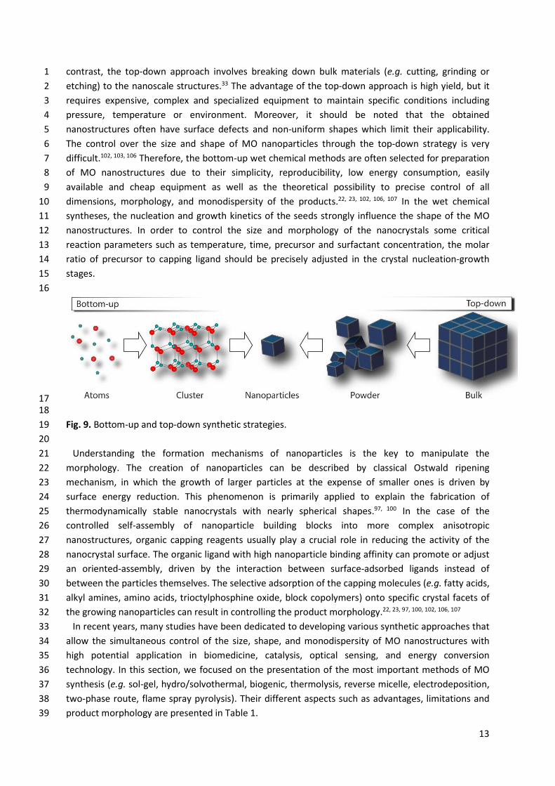
40 3.2. Synthetic strategies for metal oxide nanostructures with controlled morphology 41 MO nanomaterials can be fabricated with the use of two general strategies: bottom-up and top-42 down (Fig. 9).101, 102, 106 These synthetic strategies differ in the way how a specific nanostructure is 43 created. In the bottom-up approach, MO nanomaterials are obtained from basic building blocks (e.g. 44 atoms or molecules) that react and grow in size or self-assemble into a more complex structure. In 45
13
contrast, the top-down approach involves breaking down bulk materials (e.g. cutting, grinding or 1 etching) to the nanoscale structures.33 The advantage of the top-down approach is high yield, but it 2 requires expensive, complex and specialized equipment to maintain specific conditions including 3 pressure, temperature or environment. Moreover, it should be noted that the obtained 4 nanostructures often have surface defects and non-uniform shapes which limit their applicability. 5 The control over the size and shape of MO nanoparticles through the top-down strategy is very 6 difficult.102, 103, 106 Therefore, the bottom-up wet chemical methods are often selected for preparation 7 of MO nanostructures due to their simplicity, reproducibility, low energy consumption, easily 8 available and cheap equipment as well as the theoretical possibility to precise control of all 9 dimensions, morphology, and monodispersity of the products.22, 23, 102, 106, 107 In the wet chemical 10 syntheses, the nucleation and growth kinetics of the seeds strongly influence the shape of the MO 11 nanostructures. In order to control the size and morphology of the nanocrystals some critical 12 reaction parameters such as temperature, time, precursor and surfactant concentration, the molar 13 ratio of precursor to capping ligand should be precisely adjusted in the crystal nucleation-growth 14 stages. 15 16
17 18
Fig. 9. Bottom-up and top-down synthetic strategies. 19 20
Understanding the formation mechanisms of nanoparticles is the key to manipulate the 21 morphology. The creation of nanoparticles can be described by classical Ostwald ripening 22 mechanism, in which the growth of larger particles at the expense of smaller ones is driven by 23 surface energy reduction. This phenomenon is primarily applied to explain the fabrication of 24 thermodynamically stable nanocrystals with nearly spherical shapes.97, 100 In the case of the 25 controlled self-assembly of nanoparticle building blocks into more complex anisotropic 26 nanostructures, organic capping reagents usually play a crucial role in reducing the activity of the 27 nanocrystal surface. The organic ligand with high nanoparticle binding affinity can promote or adjust 28 an oriented-assembly, driven by the interaction between surface-adsorbed ligands instead of 29 between the particles themselves. The selective adsorption of the capping molecules (e.g. fatty acids, 30 alkyl amines, amino acids, trioctylphosphine oxide, block copolymers) onto specific crystal facets of 31 the growing nanoparticles can result in controlling the product morphology.22, 23, 97, 100, 102, 106, 107 32
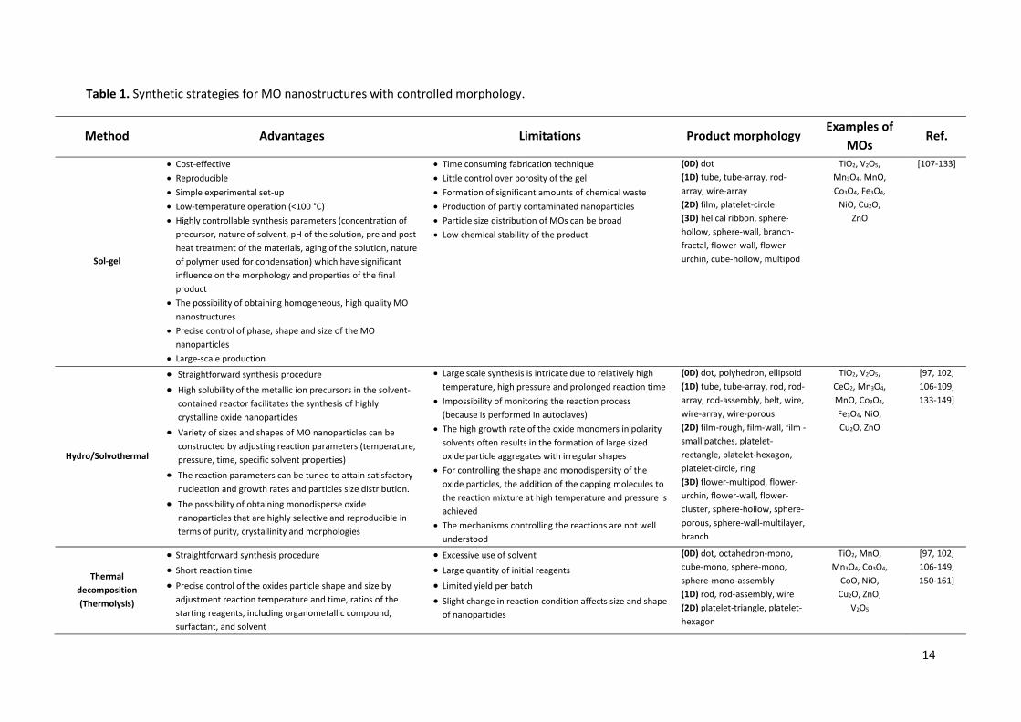
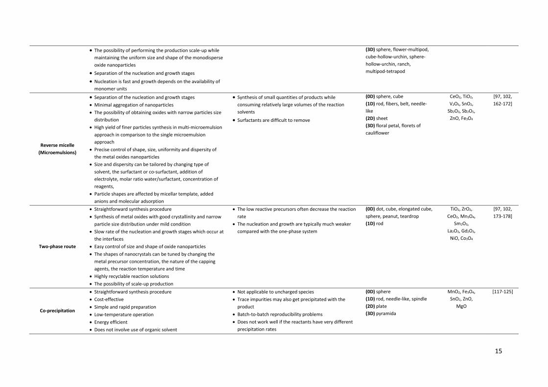
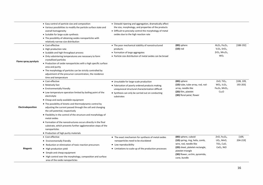
In recent years, many studies have been dedicated to developing various synthetic approaches that 33 allow the simultaneous control of the size, shape, and monodispersity of MO nanostructures with 34 high potential application in biomedicine, catalysis, optical sensing, and energy conversion 35 technology. In this section, we focused on the presentation of the most important methods of MO 36 synthesis (e.g. sol-gel, hydro/solvothermal, biogenic, thermolysis, reverse micelle, electrodeposition, 37 two-phase route, flame spray pyrolysis). Their different aspects such as advantages, limitations and 38 product morphology are presented in Table 1. 39
14
Table 1. Synthetic strategies for MO nanostructures with controlled morphology.
Method Advantages Limitations Product morphology Examples of
MOs Ref.
Sol-gel
x Cost-effective x Reproducible x Simple experimental set-up x Low-temperature operation (<100 °C) x Highly controllable synthesis parameters (concentration of
precursor, nature of solvent, pH of the solution, pre and post heat treatment of the materials, aging of the solution, nature of polymer used for condensation) which have significant influence on the morphology and properties of the final product
x The possibility of obtaining homogeneous, high quality MO nanostructures
x Precise control of phase, shape and size of the MO nanoparticles
x Large-scale production
x Time consuming fabrication technique x Little control over porosity of the gel x Formation of significant amounts of chemical waste x Production of partly contaminated nanoparticles x Particle size distribution of MOs can be broad x Low chemical stability of the product
(0D) dot (1D) tube, tube-array, rod-array, wire-array (2D) film, platelet-circle (3D) helical ribbon, sphere-hollow, sphere-wall, branch-fractal, flower-wall, flower-urchin, cube-hollow, multipod
TiO2, V2O5, Mn3O4, MnO, Co3O4, Fe3O4,
NiO, Cu2O, ZnO
[107-133]
Hydro/Solvothermal
x Straightforward synthesis procedure
x High solubility of the metallic ion precursors in the solvent-contained reactor facilitates the synthesis of highly crystalline oxide nanoparticles
x Variety of sizes and shapes of MO nanoparticles can be constructed by adjusting reaction parameters (temperature, pressure, time, specific solvent properties)
x The reaction parameters can be tuned to attain satisfactory nucleation and growth rates and particles size distribution.
x The possibility of obtaining monodisperse oxide nanoparticles that are highly selective and reproducible in terms of purity, crystallinity and morphologies
x Large scale synthesis is intricate due to relatively high temperature, high pressure and prolonged reaction time
x Impossibility of monitoring the reaction process (because is performed in autoclaves)
x The high growth rate of the oxide monomers in polarity solvents often results in the formation of large sized oxide particle aggregates with irregular shapes
x For controlling the shape and monodispersity of the oxide particles, the addition of the capping molecules to the reaction mixture at high temperature and pressure is achieved
x The mechanisms controlling the reactions are not well understood
(0D) dot, polyhedron, ellipsoid (1D) tube, tube-array, rod, rod-array, rod-assembly, belt, wire, wire-array, wire-porous (2D) film-rough, film-wall, film - small patches, platelet-rectangle, platelet-hexagon, platelet-circle, ring (3D) flower-multipod, flower-urchin, flower-wall, flower-cluster, sphere-hollow, sphere-porous, sphere-wall-multilayer, branch
TiO2, V2O5, CeO2, Mn3O4, MnO, Co3O4, Fe3O4, NiO, Cu2O, ZnO
[97, 102, 106-109, 133-149]
Thermal decomposition (Thermolysis)
x Straightforward synthesis procedure x Short reaction time
x Precise control of the oxides particle shape and size by adjustment reaction temperature and time, ratios of the starting reagents, including organometallic compound, surfactant, and solvent
x Excessive use of solvent x Large quantity of initial reagents
x Limited yield per batch x Slight change in reaction condition affects size and shape
of nanoparticles
(0D) dot, octahedron-mono, cube-mono, sphere-mono, sphere-mono-assembly (1D) rod, rod-assembly, wire (2D) platelet-triangle, platelet-hexagon
TiO2, MnO, Mn3O4, Co3O4,
CoO, NiO, Cu2O, ZnO,
V2O5
[97, 102, 106-149, 150-161]
15
x The possibility of performing the production scale-up while maintaining the uniform size and shape of the monodisperse oxide nanoparticles
x Separation of the nucleation and growth stages
x Nucleation is fast and growth depends on the availability of monomer units
(3D) sphere, flower-multipod, cube-hollow-urchin, sphere-hollow-urchin, ranch, multipod-tetrapod
Reverse micelle (Microemulsions)
x Separation of the nucleation and growth stages x Minimal aggregation of nanoparticles x The possibility of obtaining oxides with narrow particles size
distribution x High yield of finer particles synthesis in multi-microemulsion
approach in comparison to the single microemulsion approach
x Precise control of shape, size, uniformity and dispersity of the metal oxides nanoparticles
x Size and dispersity can be tailored by changing type of solvent, the surfactant or co-surfactant, addition of electrolyte, molar ratio water/surfactant, concentration of reagents,
x Particle shapes are affected by micellar template, added anions and molecular adsorption
x Synthesis of small quantities of products while consuming relatively large volumes of the reaction solvents
x Surfactants are difficult to remove
(0D) sphere, cube (1D) rod, fibers, belt, needle-like (2D) sheet (3D) floral petal, florets of cauliflower
CeO2, TiO2, V2O5, SnO2,
Sb2O3, Sb2O5, ZnO, Fe3O4
[97, 102, 162-172]
Two-phase route
x Straightforward synthesis procedure x Synthesis of metal oxides with good crystallinity and narrow
particle size distribution under mild condition x Slow rate of the nucleation and growth stages which occur at
the interfaces x Easy control of size and shape of oxide nanoparticles x The shapes of nanocrystals can be tuned by changing the
metal precursor concentration, the nature of the capping agents, the reaction temperature and time
x Highly recyclable reaction solutions x The possibility of scale-up production
x The low reactive precursors often decrease the reaction rate
x The nucleation and growth are typically much weaker compared with the one-phase system
(0D) dot, cube, elongated cube, sphere, peanut, teardrop (1D) rod
TiO2, ZrO2, CeO2, Mn3O4,
Sm2O3, La2O3, Gd2O3,
NiO, Co3O4
[97, 102, 173-178]
Co-precipitation
x Straightforward synthesis procedure x Cost-effective x Simple and rapid preparation x Low-temperature operation x Energy efficient x Does not involve use of organic solvent
x Not applicable to uncharged species x Trace impurities may also get precipitated with the
product x Batch-to-batch reproducibility problems x Does not work well if the reactants have very different
precipitation rates
(0D) sphere (1D) rod, needle-like, spindle (2D) plate (3D) pyramida
MnO2, Fe3O4, SnO2, ZnO,
MgO
[117-125]
16
x Easy control of particle size and composition x Various possibilities to modify the particle surface state and
overall homogeneity x Suitable for large-scale synthesis x The possibility of obtaining oxides nanoparticles with
relatively narrow size distribution
x Ostwald ripening and aggregation, dramatically affect the size, morphology, and properties of the products
x Difficult to precisely control the morphology of metal oxides due to the high reaction rate
Flame spray pyrolysis
x Cost-effective x High production rate x Scalable and high throughput process x Only subsintering temperatures are necessary to form
crystallized particles x Production of oxide nanoparticles with a high specific surface
area and purity x The morphology of particles can be strictly controlled by
adjustment of the precursor concentration, the residence time and temperature
x The poor mechanical stability of nanostructured products
x Formation of large aggregates x Particle size distribution of metal oxides can be broad
(0D) sphere (1D) rod
Al2O3, Fe2O3, V2O5, SnO2,
ZrO2, Mn2O3, WO3
[188-192]
Electrodeposition
x Cost-effective x Relatively fast x Environmentally friendly
x Low-temperature operation limited by boiling point of the electrolyte
x Cheap and easily available equipment
x The possibility of kinetic and thermodynamic control by adjusting the current passed through the cell and changing the cell potential, respectively
x Flexibility in the control of the structure and morphology of metal oxides
x Formation of the nanostructures occurs directly in the final substrate, which prevents further agglomeration steps of the nanoparticles
x Production of high purity materials
x Unsuitable for large-scale production x Fabrication of poorly ordered products making
unequivocal structural characterization difficult x Synthesis can only be carried out on conducting
substrates
(0D) sphere (1D) tube, tube-array, rod, rod-array, needle-like (2D) film, platelet (3D) floral petal, flower
ZnO, TiO2, WO3, V2O5,
Fe3O4, MnO2, Cu2O
[108, 109, 193-203]
Biogenic
x Cost-effective
x Environmentally friendly
x Reduction or elimination of toxic reaction precursors x High production yield
x Simple and cheap equipment x High control over the morphology, composition and surface
area of the oxide nanoparticles
x The exact mechanism for synthesis of metal oxides nanoparticles need to be elucidated
x Low reproducibility
x Limitations to scale-up of the production processes
(0D) sphere, cuboid (1D) spring, ring, helix, comb, wire, rod, needle-like (2D) sheet, platelet-rectangle, platelet-triangle (3D) flower, urchin, pyramida, cone, bundle
ZnO, Fe3O4, UO2, MnO, TiO2, CuO, CeO2, NiO
[109, 204-219]

17
x The particle size can be modulated by tuning synthesis parameters (the medium pH, temperature, concentration, incubation time, reaction time), in turn, their morphology by changing the organism (bacteria, fungi, yeast) or plants extracts used as stabilizing or reducing agents
18
3.2.1. Sol-gel method The synthesis of MO nanostructures by the sol-gel method is based upon inorganic polymerization reaction occurring through the solvolysis/condensation mechanism.23 The main step of this route comprises hydrolysis or alcoholysis of precursors (metal alkoxides, halides) to generate a colloidal solution of metal hydroxide (sol), followed by condensation leading to obtaining metal-oxygen-metal interlocked network (gel). Then the solvent is slowly removed at elevated temperature (60-100 °C). The final product with the desired crystal phase is achieved after thermal treatment causing decomposition of the residual gel.22, 23, 107-109 It has to be taken into account that the synthesis parameters including concentration of precursor, nature of solvent, pH, pre and post heat treatment strongly determine the morphology, and properties of the MO nanostructures. The sol-gel method allows to control the crystal phase, shape, and size of the materials obtained. Up to now, this synthetic route has been developed to fabricate a wide range of MOs e.g. Cu2O,110-114 Mn3O4,31, 47, 115 NiO,116, 117 V2O5,118 Fe3O4,119 Co3O4,120 TiO2,35, 37, 121-126 characterized by diverse morphology.
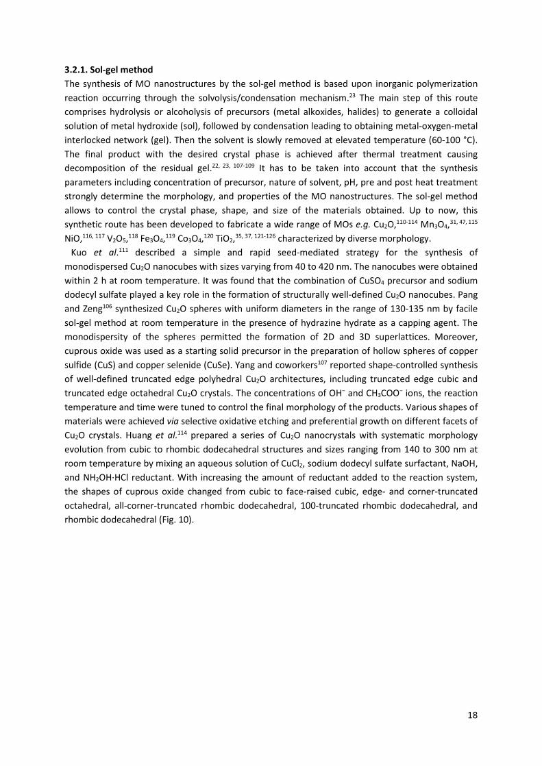
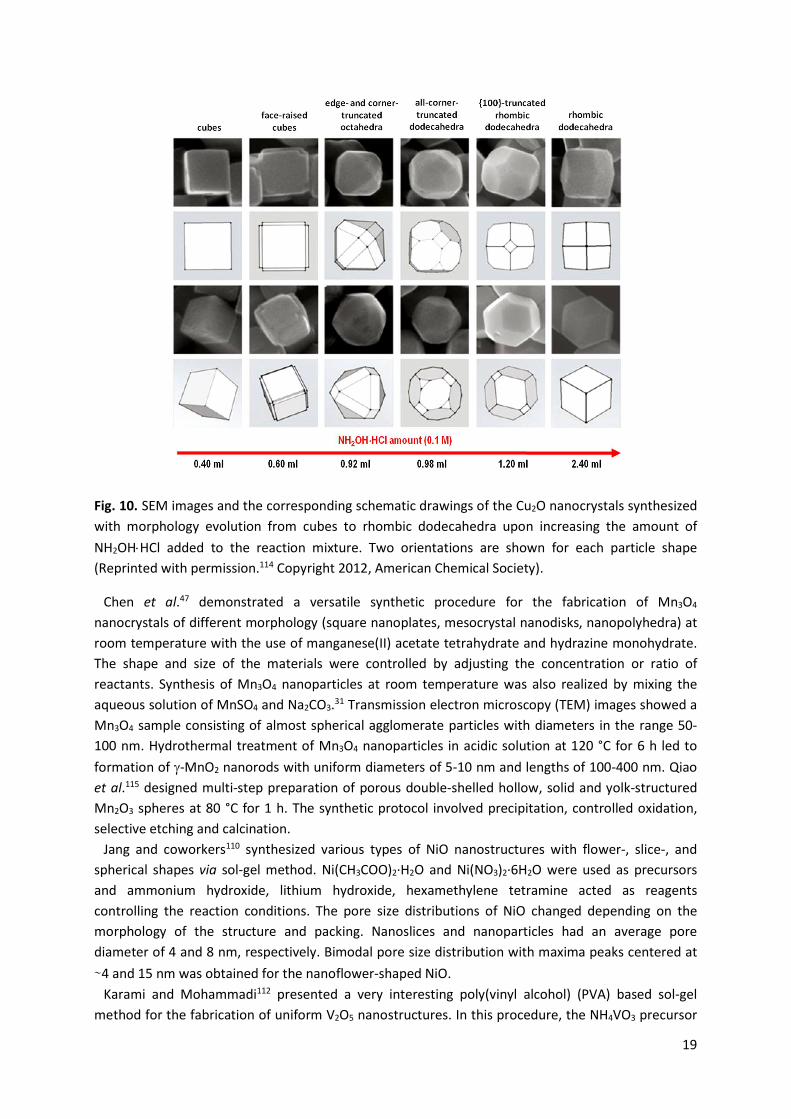
Kuo et al.111 described a simple and rapid seed-mediated strategy for the synthesis of monodispersed Cu2O nanocubes with sizes varying from 40 to 420 nm. The nanocubes were obtained within 2 h at room temperature. It was found that the combination of CuSO4 precursor and sodium dodecyl sulfate played a key role in the formation of structurally well-defined Cu2O nanocubes. Pang and Zeng106 synthesized Cu2O spheres with uniform diameters in the range of 130-135 nm by facile sol-gel method at room temperature in the presence of hydrazine hydrate as a capping agent. The monodispersity of the spheres permitted the formation of 2D and 3D superlattices. Moreover, cuprous oxide was used as a starting solid precursor in the preparation of hollow spheres of copper sulfide (CuS) and copper selenide (CuSe). Yang and coworkers107 reported shape-controlled synthesis of well-defined truncated edge polyhedral Cu2O architectures, including truncated edge cubic and truncated edge octahedral Cu2O crystals. The concentrations of OH− and CH3COO− ions, the reaction temperature and time were tuned to control the final morphology of the products. Various shapes of materials were achieved via selective oxidative etching and preferential growth on different facets of Cu2O crystals. Huang et al.114 prepared a series of Cu2O nanocrystals with systematic morphology evolution from cubic to rhombic dodecahedral structures and sizes ranging from 140 to 300 nm at room temperature by mixing an aqueous solution of CuCl2, sodium dodecyl sulfate surfactant, NaOH, and NH2OH·HCl reductant. With increasing the amount of reductant added to the reaction system, the shapes of cuprous oxide changed from cubic to face-raised cubic, edge- and corner-truncated octahedral, all-corner-truncated rhombic dodecahedral, 100-truncated rhombic dodecahedral, and rhombic dodecahedral (Fig. 10).
19
Fig. 10. SEM images and the corresponding schematic drawings of the Cu2O nanocrystals synthesized with morphology evolution from cubes to rhombic dodecahedra upon increasing the amount of NH2OH�HCl added to the reaction mixture. Two orientations are shown for each particle shape (Reprinted with permission.114 Copyright 2012, American Chemical Society).
Chen et al.47 demonstrated a versatile synthetic procedure for the fabrication of Mn3O4 nanocrystals of different morphology (square nanoplates, mesocrystal nanodisks, nanopolyhedra) at room temperature with the use of manganese(II) acetate tetrahydrate and hydrazine monohydrate. The shape and size of the materials were controlled by adjusting the concentration or ratio of reactants. Synthesis of Mn3O4 nanoparticles at room temperature was also realized by mixing the aqueous solution of MnSO4 and Na2CO3.31 Transmission electron microscopy (TEM) images showed a Mn3O4 sample consisting of almost spherical agglomerate particles with diameters in the range 50-100 nm. Hydrothermal treatment of Mn3O4 nanoparticles in acidic solution at 120 °C for 6 h led to formation of J-MnO2 nanorods with uniform diameters of 5-10 nm and lengths of 100-400 nm. Qiao et al.115 designed multi-step preparation of porous double-shelled hollow, solid and yolk-structured Mn2O3 spheres at 80 °C for 1 h. The synthetic protocol involved precipitation, controlled oxidation, selective etching and calcination.
Jang and coworkers110 synthesized various types of NiO nanostructures with flower-, slice-, and spherical shapes via sol-gel method. Ni(CH3COO)2·H2O and Ni(NO3)2·6H2O were used as precursors and ammonium hydroxide, lithium hydroxide, hexamethylene tetramine acted as reagents controlling the reaction conditions. The pore size distributions of NiO changed depending on the morphology of the structure and packing. Nanoslices and nanoparticles had an average pore diameter of 4 and 8 nm, respectively. Bimodal pore size distribution with maxima peaks centered at ∼4 and 15 nm was obtained for the nanoflower-shaped NiO.
Karami and Mohammadi112 presented a very interesting poly(vinyl alcohol) (PVA) based sol-gel method for the fabrication of uniform V2O5 nanostructures. In this procedure, the NH4VO3 precursor
20
and PVA were dissolved in an ethanol: water (70:30) mixture to obtain the sol followed by the evaporation of the solvent resulting in a homogeneous polymeric gel. The last stage of the synthesis involved calcination at 560 °C for 3 h. The results indicated that the amount of vanadium salt, gel-forming agent, solvent composition and synthesis additives strongly affected the morphology of the product. As the aforementioned parameters were changed, the shape of V2O5 nanostructures evolved from simple spherical nanoparticles to uniform nanoflakes with a mean thickness of 37 nm. The morphology of vanadium pentoxide was controlled by the gel network rigidity.
Kang et al.119 focused on the sol-gel synthesis of Fe3O4 and J-Fe2O3 nanoparticles in an aqueous solution without using any surfactant. The Fe3O4 nanoparticles were nearly spherical and had a narrow size distribution with an average diameter of 8.5 nm. Their size was smaller than other particles reported in the literature. The oxidation of Fe3O4 into J-Fe2O3 was performed by adjusting the pH of the hydrosol to about 3.5 and stirring for 30 min at 100 °C. Applying this procedure needle-like J-Fe2O3 nanoparticles with lengths of 20-50 nm and widths of 4-6 nm were synthesized.
Itteboina and Sau114 reported the preparation of morphology-controlled Co3O4 particles by a sol-gel method employing cobalt(II) chloride hexahydrate, cobalt(II) acetate tetrahydrate, cobalt(II) perchlorate hexahydrate as precursors. The shape of resulting Co3O4 particles varied from octahedral to hexagonal and planar with smooth surfaces, sharp edges or corners depending on metal salts, solvents, capping agents used in the synthetic procedure. These parameters played also a crucial role in determining particle size.
Sugimoto et al.121-124 conducted a series of studies focused on the application of the sol-gel method for the fabrication of TiO2 nanoparticles of different sizes and shapes. Titanium tetraisopropoxide was used as a precursor and different amines including triethanolamine, diethylenetriamine, ethylenediamine, trimethylenediamine, and triethylenetetramine acted as the shape controlling agents. The morphology of TiO2 nanoparticles evolved from cuboidal to ellipsoidal when synthesis was performed at pH above 11 in the presence of triethanolamine. Using diethylenetriamine at pH above 9.5 led to the formation of ellipsoidal nanoparticles with a high aspect ratio.124 Tertiary amines, such as trimethylamine and triethylamine promoted the growth of ellipsoidal particles with lower aspect ratios. The shape of the TiO2 nanoparticles was also changed from round-cornered cubes to sharp-edged cubes employing sodium oleate and sodium stearate. Tuning the growth rate of the crystal planes of TiO2 via specific adsorption of shape controlling agents under different pH conditions allowed obtaining nanoparticles with desired morphology.124 Kobayashi et al.37 described a sol-gel synthesis of TiO2 material with a hollow-fiber structure like “macaroni” using trans-(1R,2R)-1,2-cyclohexanedi-(11-aminocarbonylundecylpyridinium) hexafluorophosphate, as a template. The process involved the polymerization of titanium tetraisopropoxide and the self-assembly of the amphiphilic compound containing cationic charge moieties. Fibrous TiO2 materials were formed by the electrostatic interaction between the anionic titania species and the cationic compound serving as a template under basic conditions. In 2003, Gundiah et al.125 applied a tripodal cholamide-based hydrogel as a template to prepare TiO2 nanotubes. The diameters of the nanotubes were controlled by adopting the appropriate hydrogelator and slightly modifying the gelation conditions.
3.2.2. Hydro/Solvothermal methods Hydro/solvothermal syntheses involve chemical reactions carried out in water or organic solvents at temperatures above their boiling points and at high pressures.97, 25, 33, 102, 127-141 All reactants are placed in a sealed vessel (e.g. bomb or autoclave). These approaches are suitable for the preparation of MO nanostructures with controlled size and morphology. The most commonly used precursors are
21
aqueous solutions of salts such as metal chlorides, nitrates, sulphates or acetates. Their hydrothermal treatment can promote hydrolysis reaction.22, 23, 25, 33, 102, 106, 107, 127-141 The shape, size, and monodispersity of the MO nanostructures can be regulated by tuning the reaction parameters (e.g. temperature, time, pressure, specific properties of solvents). It should be noted that the rapid growth of oxide monomers in high-polarity solvents can lead to forming large size particle aggregates. Therefore, to control the morphology and uniformity of MO particles, various surfactants acting as capping agents are introduced into the reaction mixture.97, 102, 107 In this case, the reaction system always consists of oil, surfactant and aqueous phase. The presence of a surfactant can control the growth of the product.107
Li et al.25 prepared Mn3O4 nanocrystals with tunable sizes and shapes in the presence of dodecanol and oleylamine surfactants under mild experimental conditions. Manganese(II) nitrate was applied as a precursor. Morphology of Mn3O4 evolved from dots to rods and wires depending on concentration of metal salt, employed surfactants, volume of the solvents and reaction time. Additionally, the as-prepared hydrophobic spherical or elongated nanoparticles were assembled into three-dimensional (3D) Mn3O4 colloidal spheres using a facile ultrasonication strategy.
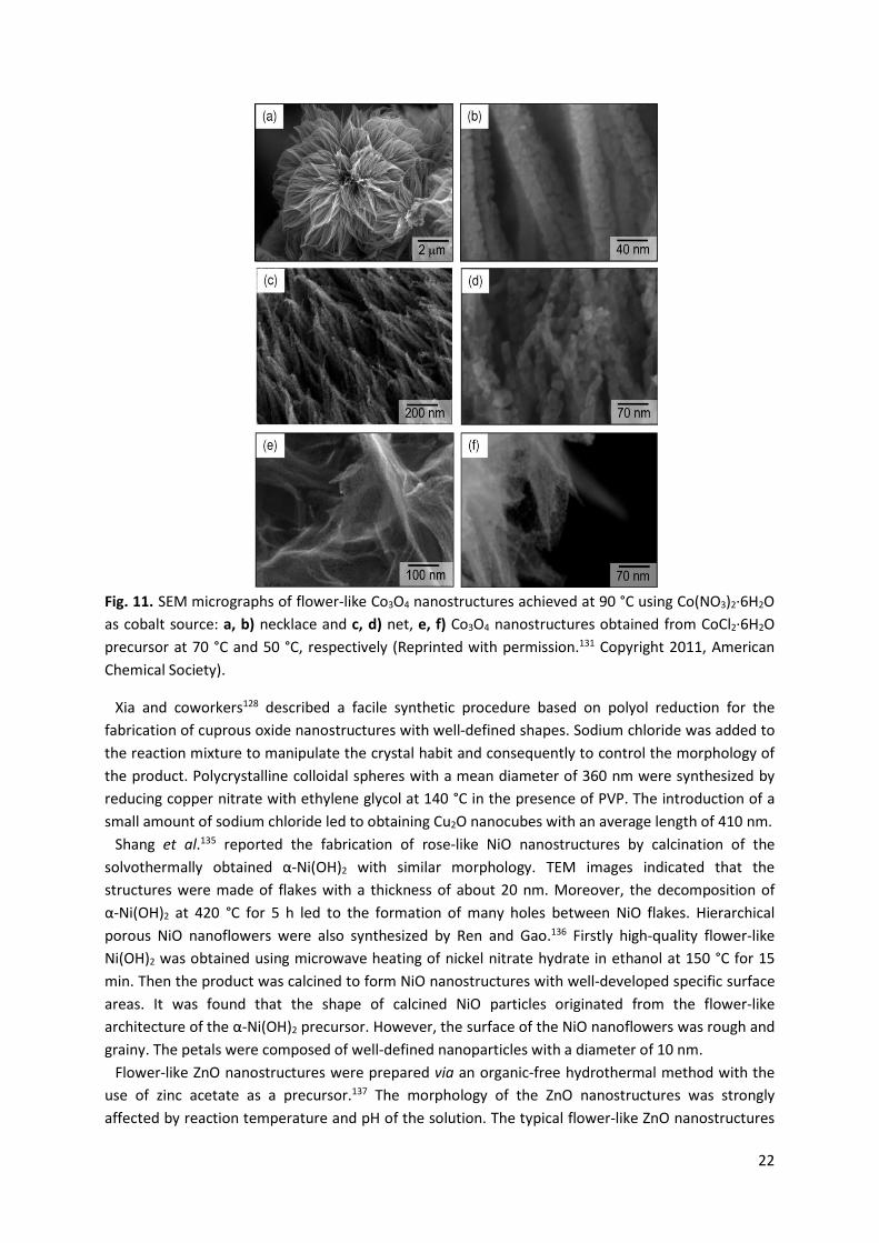
Wang et al.131 described the large-scale synthesis of Co3O4 nanostructure arrays on nickel foam substrates via hydrothermal process at a temperature range of 50-90 °C. In this procedure, different cobalt salts including CoCl2·6H2O, Co(NO3)2·6H2O or Co(CH3COO)2·4H2O were used as precursors. The shapes of the as-synthesized Co3O4 nanostructures were strongly affected by the type of cobalt precursors applied and the growth parameters. Flower-like Co3O4 structures composed of hundreds of nanorods with a length of 2-4 μm were formed at 90 °C using Co(NO3)2·6H2O as cobalt source. In turn, at 70 °C the nanorod arrays adopted a necklace-like morphology when CoCl2·6H2O was employed as a precursor. The nanorods consisted of interconnected nanocrystallites similar to those grown at 90 °C (Fig. 11). Two-step synthesis of functional Co3O4 with highly ordered structures of different shapes has been demonstrated by Wan and coworkers.132 Firstly cobalt acetate reacted with ethylene glycol in the presence of poly(vinyl pyrrolidone) (PVP), resulting in a cobalt oxide precursor which was then calcined at 500 °C for 2 h to obtain crystalline Co3O4. The morphology of the products was regulated by tuning the reaction conditions (time, initial concentration of Co(CH3COO)2·4H2O). The shape of Co3O4 varied from nanospheres to two-dimensional (2D) nanoplates and 3D cabbage-like hierarchical structures, and finally to microspheres. CoO and Co3O4 nanotubes were also prepared by solvothermal treatment of colloidal hydroxide without using any catalyst, surfactant, or template.133 CoO nanotubes obtained had an outer diameter of 18 nm and an inner diameter of about 7 nm. They were converted to Co3O4 nanotubes composed of irregular nanoparticles after annealing at 650 °C in air. It was shown that the duration of solvothermal treatment strongly influenced the morphology of the materials.
22
Fig. 11. SEM micrographs of flower-like Co3O4 nanostructures achieved at 90 °C using Co(NO3)2·6H2O as cobalt source: a, b) necklace and c, d) net, e, f) Co3O4 nanostructures obtained from CoCl2·6H2O precursor at 70 °C and 50 °C, respectively (Reprinted with permission.131 Copyright 2011, American Chemical Society).
Xia and coworkers128 described a facile synthetic procedure based on polyol reduction for the fabrication of cuprous oxide nanostructures with well-defined shapes. Sodium chloride was added to the reaction mixture to manipulate the crystal habit and consequently to control the morphology of the product. Polycrystalline colloidal spheres with a mean diameter of 360 nm were synthesized by reducing copper nitrate with ethylene glycol at 140 °C in the presence of PVP. The introduction of a small amount of sodium chloride led to obtaining Cu2O nanocubes with an average length of 410 nm.
Shang et al.135 reported the fabrication of rose-like NiO nanostructures by calcination of the solvothermally obtained α-Ni(OH)2 with similar morphology. TEM images indicated that the structures were made of flakes with a thickness of about 20 nm. Moreover, the decomposition of α-Ni(OH)2 at 420 °C for 5 h led to the formation of many holes between NiO flakes. Hierarchical porous NiO nanoflowers were also synthesized by Ren and Gao.136 Firstly high-quality flower-like Ni(OH)2 was obtained using microwave heating of nickel nitrate hydrate in ethanol at 150 °C for 15 min. Then the product was calcined to form NiO nanostructures with well-developed specific surface areas. It was found that the shape of calcined NiO particles originated from the flower-like architecture of the α-Ni(OH)2 precursor. However, the surface of the NiO nanoflowers was rough and grainy. The petals were composed of well-defined nanoparticles with a diameter of 10 nm.
Flower-like ZnO nanostructures were prepared via an organic-free hydrothermal method with the use of zinc acetate as a precursor.137 The morphology of the ZnO nanostructures was strongly affected by reaction temperature and pH of the solution. The typical flower-like ZnO nanostructures
23
consisted of sword-like ZnO nanorods with width in the range of 60-200 nm and several micrometers in length.
In 2007, He et al.138 presented a simple hydrothermal route performed in the presence of polyethylene glycol 400 (PEG 400) at 150 °C for the synthesis of uniform, single-crystalline Fe3O4 nanowires. Ferrous sulphate was selected as a precursor. The nanowires obtained had a narrow size distribution centered at 15 nm and length up to 3 µm. Wan et al.139 prepared uniform single-crystal Fe3O4 nanorods via a soft template-assisted hydrothermal route at 120 °C for 20 h. In this procedure, ethylenediamine was used as a soft template and benzene as an oil membrane for preventing oxidation of ferrous ions. It was found that as-synthesized product mainly consisted of uniform Fe3O4 nanorods with an average diameter of 25 nm and length of 200 nm. A single crystalline triangular Fe3O4 nanoprisms employing a direct hydrothermal method in the presence of 1,3-propanediamine (PDA) and ethylene glycol (EG) were fabricated by Li et al.140 The synthesis was carried out in autoclave at 200 °C for 12 h with FeCl3·6H2O as iron source. Magnetite nanostructures were mainly composed of triangular nanoprisms with average edge length and thickness of 113 nm and 25 nm, respectively. A small fraction of the polyhedral nanoparticles with an average size of 40 nm was also observed. The morphology evolution of the Fe3O4 was controlled by tuning the volume ratio of EG to PDA.
Dinh et al.141 developed a versatile solvothermal method for obtaining titania nanocrystals with various shapes including rhombic, truncated rhombic, spherical, dog-bone, truncated and elongated rhombic or bar. In the synthetic protocol, water vapor was applied to accelerate controlled hydrolysis of titanium butoxide to form TiO2 nanoparticles, while oleic acid and oleylamine were adopted as two distinct capping surfactants. The morphology control of titania was realized by tuning oleic acid: oleylamine ratio and reaction temperature. It was shown that the shape of the TiO2 evolved from rhombic to truncated rhombic and sphere with increasing ratio of surfactants from 4:6 to 5:5 and 6:4. In turn, when the molar ratio of titanium precursor to oleic acid and oleylamine was changed from 1:6:4 to 2:6:4 the morphology of TiO2 nanocrystals transformed from spheres to dog-bone.
3.2.3. Thermal decomposition (Thermolysis) MO nanostructures with desired size and shape can be obtained by thermal decomposition of organometallic compounds in high-boiling, coordinating or non-coordinating organic solvents (e.g. 1-octadecene, benzyl ether, phenyl ether, trioctylamine) containing surfactant as a stabilizing agent at high temperature and ambient pressure.22, 23, 107, 142-153 In this procedure, metal acetylacetonates, acetates, oxalates, cupferronates, alkoxides or carbonyls are often applied as organometallic precursors while fatty acids, aliphatic amines, alkyl phosphonic acids, and alkyl thiols can serve as capping agents.142-153 The ratio of the starting reagents such as metal-organic salts, solvents, surfactants, and specific reaction conditions (e.g. time and temperature) have a direct influence on the obtained morphology. Additionally, the choice of appropriate organometallic compounds and the balance between nucleation and growth stages are important for the synthesis of highly monocrystalline products. MO nanoparticles achieved by thermal decomposition are monodisperse in shape and size. In the thermolysis, the stages of nucleation and growth occur separately, because the preformed nuclei are added to the reaction solution containing the monomers that subsequently grow on the surface of small particles without further nucleation. Consequently, precise control of the morphology of MO nanoparticles is possible.102, 141-153
Up to now, facile thermal decomposition method was used to obtain samaria (Sm2O3) nanowires and nanoplates.146 Sm2O3 nanowires with a rectangular shape were synthesized by the thermolysis of
24
hydrated samarium(III) acetate in the presence of a mixture of oleylamine and decanoic acid under argon atmosphere. They had uniform thickness of about 1 nm and width of 2 nm, with lengths of more than 1 µm. Due to the high surface energy, the nanowires generated parallel arrays via the self-assemby process. When in the synthesis the oleic acid with oleylamine were used as surfactants, square-shaped Sm2O3 nanoplates having a thickness of ~1 nm were formed. Nanoplates of other rare-earth metal oxides, such as La2O3, Nd2O3, Y2O3, and Pr2O3, were achieved employing a very similar procedure. Cao et al.147 described the fabrication of Gd2O3 nanoplates by thermal decomposition of gadolinium-acetate precursor in hot octadecene containing oleylamine and oleic acid. Evaporation of the solvent during sample preparation for TEM analysis led to the assembly of Gd2O3 nanoplates into ribbons of stacked plates.
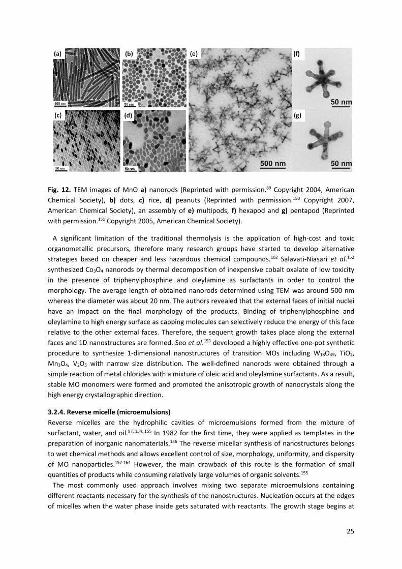
Hyeon et al.148 described the synthesis of highly crystalline and monodisperse J-Fe2O3 with a size in the range of 4-16 nm by thermal decomposition of iron pentacarbonyl (Fe(CO)5) in the presence of oleic acid. High temperature (300 °C) aging of iron-oleic acid metal complex caused the formation of iron nanoparticles that were transformed in the next step to J-Fe2O3 by controlled oxidation with the use of trimethylamine oxide as a mild oxidant. Moreover, monodisperse γ-Fe2O3 nanocrystallites with a particle size of 13 nm can be generated via the direct oxidation of Fe(CO)5 with trimethylamine oxide in the presence of oleic acid. In both approaches, it is possible to obtain 2-dimensional or 3-dimensional close-packed superlattice. The authors revealed that during the thermal decomposition of Fe(CO)5 the nucleation occurs at low temperature, whereas the growth derived from the decomposition of the iron oleate complex takes place at a higher temperature. These stages should be separated. A similar procedure was applied for the synthesis of MnO nanorods and nanospheres.149 These nanostructures were fabricated by thermal decomposition of Mn-surfactant complexes prepared by reacting Mn2(CO)10 with oleylamine at 100 °C. The morphology of the MnO nanoparticles was precisely controlled by tuning the reaction temperature. The one-dimensional nanorods were generated when two surfactants with different stabilizing capabilities were employed under kinetically controlled conditions, such as those requiring rapid thermal decomposition at high temperature (Fig. 12a). Spherical nanoparticles were formed under thermodynamically controlled conditions, i.e. corresponding to the slow decomposition of the precursors over a long time. The sizes of MnO nanoparticles were controlled by varying the stabilizing agents (trioctylphosphine, triphenylphosphine). The diameters of MnO nanospheres were in the range of 5 to 40 nm. MnO nanorods had dimensions of 7 nm (diameter) × 33 nm (length) and 8 nm (diameter) × 140 nm (length). Formation of monodisperse MnO nanocrystals by simple heating of manganese(II) stearate in octadecene was systematically studied by Chen et al.150 The authors observed that the shape of manganese(II) oxide nanocrystals (rice, rods, peanuts, needles, dots) can be changed by adding an activation reagent (ocadecanol) or an inhibitor (stearic acid) to the system prior to heating (Fig. 12b, c, d). Zitoun et al.151 reported the application of the thermal decomposition approach for the production of MnO multipods (Fig. 12e, f, g). The Mn(oleate)2 prepared from manganese acetate and sodium oleate was used as a precursor. The mechanism of MnO particles formation involved two stages: (i) the nucleation of truncated octahedra or cubes and (ii) the growth of homogeneous pods. The rate of the precipitation of multipods strongly determined their overall size and arm lengths.
25
Fig. 12. TEM images of MnO a) nanorods (Reprinted with permission.89 Copyright 2004, American Chemical Society), b) dots, c) rice, d) peanuts (Reprinted with permission.150 Copyright 2007, American Chemical Society), an assembly of e) multipods, f) hexapod and g) pentapod (Reprinted with permission.151 Copyright 2005, American Chemical Society).
A significant limitation of the traditional thermolysis is the application of high-cost and toxic organometallic precursors, therefore many research groups have started to develop alternative strategies based on cheaper and less hazardous chemical compounds.102 Salavati-Niasari et al.152 synthesized Co3O4 nanorods by thermal decomposition of inexpensive cobalt oxalate of low toxicity in the presence of triphenylphosphine and oleylamine as surfactants in order to control the morphology. The average length of obtained nanorods determined using TEM was around 500 nm whereas the diameter was about 20 nm. The authors revealed that the external faces of initial nuclei have an impact on the final morphology of the products. Binding of triphenylphosphine and oleylamine to high energy surface as capping molecules can selectively reduce the energy of this face relative to the other external faces. Therefore, the sequent growth takes place along the external faces and 1D nanostructures are formed. Seo et al.153 developed a highly effective one-pot synthetic procedure to synthesize 1-dimensional nanostructures of transition MOs including W18O49, TiO2, Mn3O4, V2O5 with narrow size distribution. The well-defined nanorods were obtained through a simple reaction of metal chlorides with a mixture of oleic acid and oleylamine surfactants. As a result, stable MO monomers were formed and promoted the anisotropic growth of nanocrystals along the high energy crystallographic direction.
3.2.4. Reverse micelle (microemulsions) Reverse micelles are the hydrophilic cavities of microemulsions formed from the mixture of surfactant, water, and oil.97, 154, 155 In 1982 for the first time, they were applied as templates in the preparation of inorganic nanomaterials.156 The reverse micellar synthesis of nanostructures belongs to wet chemical methods and allows excellent control of size, morphology, uniformity, and dispersity of MO nanoparticles.157-164 However, the main drawback of this route is the formation of small quantities of products while consuming relatively large volumes of organic solvents.155
The most commonly used approach involves mixing two separate microemulsions containing different reactants necessary for the synthesis of the nanostructures. Nucleation occurs at the edges of micelles when the water phase inside gets saturated with reactants. The growth stage begins at
26
the interface and then shifts into the core of the micelle. It should be noted that the intermicellar exchange limits the growth rate of nanoparticles. Another approach used for the synthesis of nanoparticles is based on the preparation of single microemulsion and then successive diffusion of chemical compounds into the interior of reverse micelles where the proper reaction occurs. The problem with this procedure is that the composition of the microemulsion is gradually changed by adding solutions of different reactants, which causes significant modification of the micelle properties.155, 157-164
The morphology of the obtained nanostructures is determined by three main factors: (i) micellar template, (ii) added anions, and (iii) molecular adsorption. A surfactant-water-oil system can create various self-assembly structures such as spheres, cylinders, interconnected cylinders, and planes termed lamellar phase, which can transform into onion-type structures. Therefore, many nanoparticles of different shapes could be grown inside these templates.97, 102, 154, 155
Gu et al.160 successfully synthesized one-dimensional mesoporous ceria nanofibers and nanobelts with the use of reverse micelle method. In an applied procedure, Ce2(CO)3 nanofibers, acting as precursors, were prepared by rapidly pouring the reverse micelles I (Triton X-100, cyclohexane, n-hexacohol, Ce(NO3)3 hydrous solution) into the reverse micelles II (Triton X-100, n-hexacohol, cyclohexane, NH4HCO3 hydrous solution). In the next step, the mixture was aged for 48 h at 30 or 40 °C and then precipitate was dried and calcined to obtain CeO2 nanostructures. Studies have revealed that the aging temperature is a key parameter to control the morphology of ceria. CeO2 nanofibers were formed when the aging temperature during synthesis was 30 °C. The diameter of the nanofibers was estimated to be 50-200 nm and the length was more than 50 µm. Performing the aging process at 40 °C resulted in the fabrication of CeO2 nanobelts with a length of a few tens of micrometers, a width ranging from 0.5 to 5 µm and a thickness varying from 20 to 100 nm. Kuiry et al.161 described the preparation of CeO2 nanorods by self-assembling the crystalline ceria nanoparticles utilizing a double microemulsion procedure. Microemulsion I consisted of cerium nitrate dissolved in the sodium bis(2-ethylhexyl) sulfosuccinate (AOT)-in-toluene solution, whereas microemulsion II was obtained by adding H2O2 to the AOT-in-toluene solution. These microemulsions were mixed and aged for a few weeks. The self-assembly process occured during aging of the sol after the formation of CeO2 nanoparticles, leading to the gradual evolution of ceria nanorods. The authors proposed a mechanism of this process involving the creation of cylindrical supra-aggregates and their subsequent growth by preferential assembly of ceria nanocrystallites along the longitudinal direction. The nanorods achieved with this procedure had a diameter of 40 nm and a length of 250 nm.
Li et al.162 obtained TiO2 nanoparticles with controlled morphology and high photoactivity using microemulsion-mediated hydrothermal method. The microemulsion was prepared by introducing Triton-X-100 and water into the mixture of heptane and hexanol. Titanium isopropoxide as precursor was directly added into microemulsion. In this procedure, hydrothermal treatment was carried out for 13 h at different temperatures which had a direct impact on the morphology of TiO2. As the temperature of the hydrothermal treatment increased, the shape of titania particles changed from spherical into rod-like. The results indicated that spherical particles with diameters 6-10 nm grow into rods along their preferred (101) direction confirming that the microemulsion droplet provides a large space for nuclei growth of titania due to a decrease in the interface strength and an increase in the collision efficiency between droplets at high temperature.
Bumajdad et al.163 synthesized zinc oxide nanostructures with various shapes (spherical, needle-like, acicular) using water-in-n-heptane microemulsion (relatively insensitive towards precursor
27
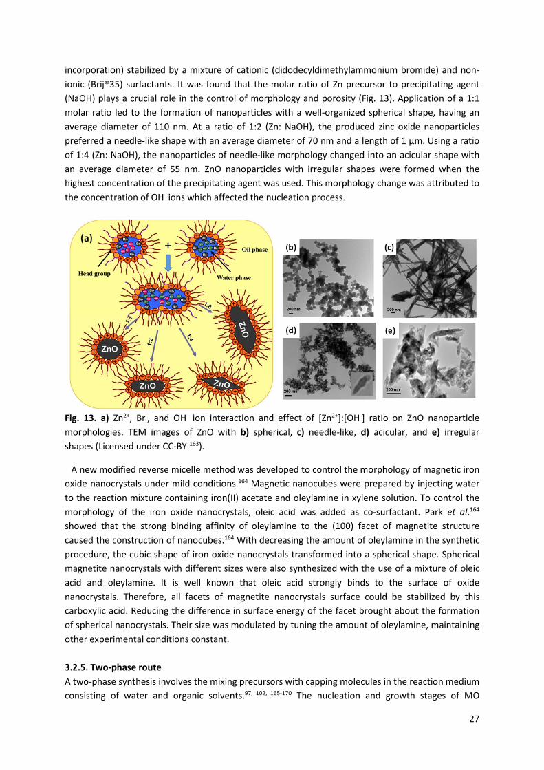
incorporation) stabilized by a mixture of cationic (didodecyldimethylammonium bromide) and non-ionic (Brij®35) surfactants. It was found that the molar ratio of Zn precursor to precipitating agent (NaOH) plays a crucial role in the control of morphology and porosity (Fig. 13). Application of a 1:1 molar ratio led to the formation of nanoparticles with a well-organized spherical shape, having an average diameter of 110 nm. At a ratio of 1:2 (Zn: NaOH), the produced zinc oxide nanoparticles preferred a needle-like shape with an average diameter of 70 nm and a length of 1 µm. Using a ratio of 1:4 (Zn: NaOH), the nanoparticles of needle-like morphology changed into an acicular shape with an average diameter of 55 nm. ZnO nanoparticles with irregular shapes were formed when the highest concentration of the precipitating agent was used. This morphology change was attributed to the concentration of OH- ions which affected the nucleation process.
Fig. 13. a) Zn2+, Br-, and OH- ion interaction and effect of [Zn2+]:[OH-] ratio on ZnO nanoparticle morphologies. TEM images of ZnO with b) spherical, c) needle-like, d) acicular, and e) irregular shapes (Licensed under CC-BY.163).
A new modified reverse micelle method was developed to control the morphology of magnetic iron oxide nanocrystals under mild conditions.164 Magnetic nanocubes were prepared by injecting water to the reaction mixture containing iron(II) acetate and oleylamine in xylene solution. To control the morphology of the iron oxide nanocrystals, oleic acid was added as co-surfactant. Park et al.164 showed that the strong binding affinity of oleylamine to the (100) facet of magnetite structure caused the construction of nanocubes.164 With decreasing the amount of oleylamine in the synthetic procedure, the cubic shape of iron oxide nanocrystals transformed into a spherical shape. Spherical magnetite nanocrystals with different sizes were also synthesized with the use of a mixture of oleic acid and oleylamine. It is well known that oleic acid strongly binds to the surface of oxide nanocrystals. Therefore, all facets of magnetite nanocrystals surface could be stabilized by this carboxylic acid. Reducing the difference in surface energy of the facet brought about the formation of spherical nanocrystals. Their size was modulated by tuning the amount of oleylamine, maintaining other experimental conditions constant.
3.2.5. Two-phase route A two-phase synthesis involves the mixing precursors with capping molecules in the reaction medium consisting of water and organic solvents.97, 102, 165-170 The nucleation and growth stages of MO
28
nanoparticles occur at the interface of two immiscible liquid phases during thermal treatment. The initial nuclei grow to form capping-assisted oxide nanoparticles which are highly dispersed in the nonpolar organic solvent. Then the product is precipitated by adding excess ethanol or methanol and recovered by centrifugation and decantation. In this method, MO nanocrystals are stabilized in the solution by the organic capping layer adsorbed on their surface. In comparison to the single-phase synthetic approaches, the two-phase strategy also leads to obtaining high crystallinity products under relatively mild conditions, thanks to the presence of the aqueous phase, which increases the speed of the growth process. Due to the slow rate of nucleation and growth occurring at the liquid-liquid interface, it is possible to precisely control the particle size and morphology.97, 102, 165-170
Zhao et al.165 described a two-phase synthesis of Mn3O4 nanocrystals that were capped with an organic ligand (dodecylamine) and dissolved in a nonpolar solvent. In this synthetic procedure, manganese(II) stearate was used as a precursor. The morphology and size of the product were controlled by changing reaction conditions (e.g. time, temperature, activation agent concentration). The results have shown that the cubic nanocrystals were fabricated in the early stages of the anisotropic growth. With increasing the reaction time, the monomer concentration was gradually reduced and the energetically unfavorable cubes transformed into spheres. The Mn3O4 nanoparticles obtained at relatively low temperature (120 °C) had cubic shape and the average size of 8 nm, whereas the spheres with a diameter of about 5 nm were synthesized at 180 °C.
Ji and coworkers160 developed a two-phase approach for the preparation of zirconia nanoparticles with spherical, teardrop, rod and rice shapes. The synthesis was performed by the mixing of zirconium(IV) n-propoxide and oleic acid in the toluene-tert-butylamine-water system and then thermal treatment at a temperature in the range 120-180 °C. It was found that the reaction time, temperature, the nature of the capping agent, and the monomer concentration are key factors for controlling the shape of ZrO2 nanoparticles. The change of zirconia morphology was the result of both the martensitic transformation and the diffusion mechanism, which influenced the nucleation and growth, respectively.
Nguyen and Do161 reported different two-phase methods for synthesis of rare earth oxides (Sm2O3, CeO2, Er2O3, Gd2O3, La2O3, Y2O3) and transition metal oxides (Mn3O4, Cr2O3, Co3O4, NiO) with controlled size and shape, through the hydrolysis of corresponding inorganic salts or metal-surfactant complexes in the water-toluene system. The advantages of these approaches are mild reaction conditions, high yields, and easy tunability of the product morphology. Depending on the nature of the metal precursors, the nanoparticles obtained had spherical, cubic, peanut, rod or hexagonal shapes. Moreover, it was observed that when the monomer concentration of cerium salts rose from 0.015 to 0.120 M, the shape of CeO2 nanoparticles changed from nanocubes to elongated nanocubes, what could be associated with an increase in the chemical potential in bulk solution. In turn, the morphology of Co3O4 nanoparticles transformed from nanocubes to nanospheres with increasing reaction time up to 24 h at 180 °C because of the differences in chemical potential between different facets of the nanocrystals.
Nguyen et al.168 proposed a low cost and reproducible preparation of samaria spheres and rods from inexpensive Sm2O3 powders and various capping long-chain alkyl acids with the use of two-phase hydrothermal method. The shape of nanoparticles was controlled by reaction temperature while the diameters of rods were controlled by the alkyl chain length of capping agents. The Sm2O3 nanocrystals synthesis occurred through two mechanisms: Ostwald ripening (nucleation and growth) in the case of spherical nanoparticles generation and the oriented attachment for the formation of rods from nanoparticles.
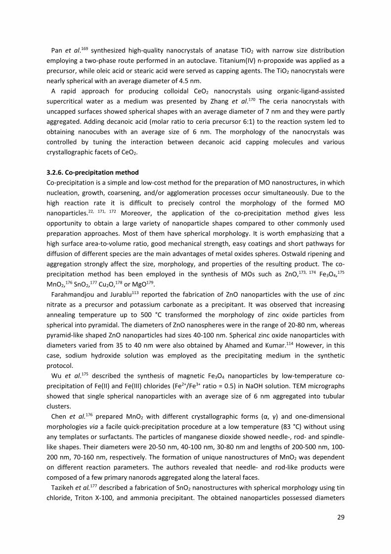
29
Pan et al.169 synthesized high-quality nanocrystals of anatase TiO2 with narrow size distribution employing a two-phase route performed in an autoclave. Titanium(IV) n-propoxide was applied as a precursor, while oleic acid or stearic acid were served as capping agents. The TiO2 nanocrystals were nearly spherical with an average diameter of 4.5 nm.
A rapid approach for producing colloidal CeO2 nanocrystals using organic-ligand-assisted supercritical water as a medium was presented by Zhang et al.170 The ceria nanocrystals with uncapped surfaces showed spherical shapes with an average diameter of 7 nm and they were partly aggregated. Adding decanoic acid (molar ratio to ceria precursor 6:1) to the reaction system led to obtaining nanocubes with an average size of 6 nm. The morphology of the nanocrystals was controlled by tuning the interaction between decanoic acid capping molecules and various crystallographic facets of CeO2.
3.2.6. Co-precipitation method Co-precipitation is a simple and low-cost method for the preparation of MO nanostructures, in which nucleation, growth, coarsening, and/or agglomeration processes occur simultaneously. Due to the high reaction rate it is difficult to precisely control the morphology of the formed MO nanoparticles.22, 171, 172 Moreover, the application of the co-precipitation method gives less opportunity to obtain a large variety of nanoparticle shapes compared to other commonly used preparation approaches. Most of them have spherical morphology. It is worth emphasizing that a high surface area-to-volume ratio, good mechanical strength, easy coatings and short pathways for diffusion of different species are the main advantages of metal oxides spheres. Ostwald ripening and aggregation strongly affect the size, morphology, and properties of the resulting product. The co-precipitation method has been employed in the synthesis of MOs such as ZnO,173, 174 Fe3O4,175 MnO2,176 SnO2,177 Cu2O,178 or MgO179.
Farahmandjou and Jurablu113 reported the fabrication of ZnO nanoparticles with the use of zinc nitrate as a precursor and potassium carbonate as a precipitant. It was observed that increasing annealing temperature up to 500 °C transformed the morphology of zinc oxide particles from spherical into pyramidal. The diameters of ZnO nanospheres were in the range of 20-80 nm, whereas pyramid-like shaped ZnO nanoparticles had sizes 40-100 nm. Spherical zinc oxide nanoparticles with diameters varied from 35 to 40 nm were also obtained by Ahamed and Kumar.114 However, in this case, sodium hydroxide solution was employed as the precipitating medium in the synthetic protocol.
Wu et al.175 described the synthesis of magnetic Fe3O4 nanoparticles by low-temperature co-precipitation of Fe(II) and Fe(III) chlorides (Fe2+/Fe3+ ratio = 0.5) in NaOH solution. TEM micrographs showed that single spherical nanoparticles with an average size of 6 nm aggregated into tubular clusters.
Chen et al.176 prepared MnO2 with different crystallographic forms (α, γ) and one-dimensional morphologies via a facile quick-precipitation procedure at a low temperature (83 °C) without using any templates or surfactants. The particles of manganese dioxide showed needle-, rod- and spindle-like shapes. Their diameters were 20-50 nm, 40-100 nm, 30-80 nm and lengths of 200-500 nm, 100-200 nm, 70-160 nm, respectively. The formation of unique nanostructures of MnO2 was dependent on different reaction parameters. The authors revealed that needle- and rod-like products were composed of a few primary nanorods aggregated along the lateral faces.
Tazikeh et al.177 described a fabrication of SnO2 nanostructures with spherical morphology using tin chloride, Triton X-100, and ammonia precipitant. The obtained nanoparticles possessed diameters
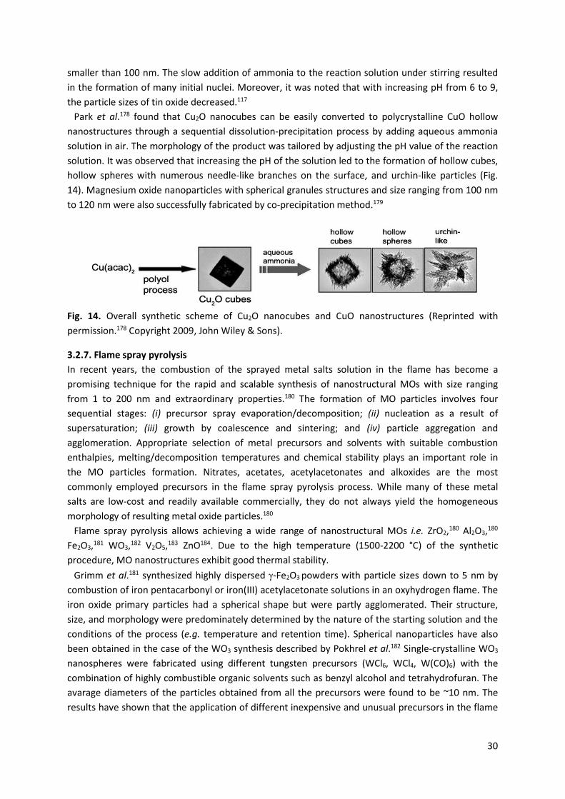
30
smaller than 100 nm. The slow addition of ammonia to the reaction solution under stirring resulted in the formation of many initial nuclei. Moreover, it was noted that with increasing pH from 6 to 9, the particle sizes of tin oxide decreased.117
Park et al.178 found that Cu2O nanocubes can be easily converted to polycrystalline CuO hollow nanostructures through a sequential dissolution-precipitation process by adding aqueous ammonia solution in air. The morphology of the product was tailored by adjusting the pH value of the reaction solution. It was observed that increasing the pH of the solution led to the formation of hollow cubes, hollow spheres with numerous needle-like branches on the surface, and urchin-like particles (Fig. 14). Magnesium oxide nanoparticles with spherical granules structures and size ranging from 100 nm to 120 nm were also successfully fabricated by co-precipitation method.179
Fig. 14. Overall synthetic scheme of Cu2O nanocubes and CuO nanostructures (Reprinted with permission.178 Copyright 2009, John Wiley & Sons).
3.2.7. Flame spray pyrolysis In recent years, the combustion of the sprayed metal salts solution in the flame has become a promising technique for the rapid and scalable synthesis of nanostructural MOs with size ranging from 1 to 200 nm and extraordinary properties.180 The formation of MO particles involves four sequential stages: (i) precursor spray evaporation/decomposition; (ii) nucleation as a result of supersaturation; (iii) growth by coalescence and sintering; and (iv) particle aggregation and agglomeration. Appropriate selection of metal precursors and solvents with suitable combustion enthalpies, melting/decomposition temperatures and chemical stability plays an important role in the MO particles formation. Nitrates, acetates, acetylacetonates and alkoxides are the most commonly employed precursors in the flame spray pyrolysis process. While many of these metal salts are low-cost and readily available commercially, they do not always yield the homogeneous morphology of resulting metal oxide particles.180
Flame spray pyrolysis allows achieving a wide range of nanostructural MOs i.e. ZrO2,180 Al2O3,180 Fe2O3,181 WO3,182 V2O5,183 ZnO184. Due to the high temperature (1500-2200 °C) of the synthetic procedure, MO nanostructures exhibit good thermal stability.
Grimm et al.181 synthesized highly dispersed J-Fe2O3 powders with particle sizes down to 5 nm by combustion of iron pentacarbonyl or iron(III) acetylacetonate solutions in an oxyhydrogen flame. The iron oxide primary particles had a spherical shape but were partly agglomerated. Their structure, size, and morphology were predominately determined by the nature of the starting solution and the conditions of the process (e.g. temperature and retention time). Spherical nanoparticles have also been obtained in the case of the WO3 synthesis described by Pokhrel et al.182 Single-crystalline WO3 nanospheres were fabricated using different tungsten precursors (WCl6, WCl4, W(CO)6) with the combination of highly combustible organic solvents such as benzyl alcohol and tetrahydrofuran. The avarage diameters of the particles obtained from all the precursors were found to be ~10 nm. The results have shown that the application of different inexpensive and unusual precursors in the flame
31
spray pyrolysis technique opens new opportunities for the production of ultrafine single-crystalline MO nanomaterials.
Sel et al.183 reported the application of flame spray pyrolysis for the preparation of orthorhombic vanadium pentoxide (V2O5) nanoparticles. In the synthetic protocol, vanadium oxotriisopropoxide dissolved in propionic acid was employed as a precursor. It was observed that spherical primary nanoparticles with the avarage diameter of 20 nm formed chain-like aggregate structures having polydisperse size distribution.
Height et al.184 demonstrated direct synthesis of ZnO nanorods with controlled aspect ratio by flame spray pyrolysis using zinc naphthenate as a precursor and dopant species such as indium acetyl acetonate, stannous 2-ethyl hexanoate and lithium tert-butoxide. It was shown that tin and indium dopants had an influence on formation of specific zinc oxide crystal plane. They were incorporated into certain crystal lattice, thereby disrupting the crystal growth. Nanorod formation was attributed to the higher valency and coordination of indium and tin dopants in comparison to zinc. Lithium, with an equivalent ionic radius to other dopants but lower valency than zinc, does not affect the ZnO morphology. The final rod shape was mainly associated with particle annealing and rearrangement during the flame cooling.
3.2.8. Electrodeposition Electrochemical methods of synthesis (i.e., electrodeposition - ED, electrophoretic deposition - EPD) can be applied to obtain various MO nanostructures with desired shape and dimensions.49, 50, 185-193 The reaction occurs at the interface of electrode-electrolyte and does not require elevated temperature. The product is deposited on the electrode surface in the form of a coating or thin film having specific morphology. The film structure can be controlled by changing the bath composition and parameters of the electrochemical processes. Other advantages of these methods include the high growth rate, low cost, and the possibility of using different types of substrates.49, 50, 185-193
Lu and Zhou183 described a fabrication of vanadium oxide films by facile electrochemical deposition method on ITO-coated glass substrates at +2.0 V for 3 min and thermal treatment at 400 °C for 6 h. Vanadium(IV) oxide sulfate was used as a precursor and Triton X-100 polymer surfactant with different concentrations was selected as a templating agent to control the morphology of the nanostructures. Nanorods with diameters of about 62 nm and lengths range of 200-400 nm were synthesized in the presence of 100 mM polymer surfactant. A reduction of Triton X-100 concentration to 50 mM led to formation of irregular vanadium oxide nanoparticles having different diameters of 39 nm. Without using polymer surfactant after thermal treatment irregularly shaped crystal platelets were fabricated. Lu et al.190 also prepared V2O5 films by electrodeposition performed at -0.7 V against the reference electrode for 20, 40, and 60 s. It was observed that vanadium oxide thin films deposited for 20 s were relatively smooth and adhered very well onto the substrate. As the deposition time rose to 40 and 60 s, the morphology of the V2O5 films transformed from smooth into typical sea-island.
Hassan and Hashim43 demonstrated that time of the process strongly affected the shape and size of the ZnO nanostructures electrochemically deposited on silicon Si (111) using 0.1 M of Zn(NO3)2·6H2O aqueous solutions at room temperature. Zinc oxide nanostructure exhibited a high-quality flakes-like morphology. The authors suggested that during the synthetic procedure Zn2+ in the solution moved toward the cathode and condensed to Zn droplets on the silicon. The Zn droplets reacted with hydroxide to form ZnO. Yang et al.191 synthesized zinc oxide nanotube arrays on ITO-coated glass substrates by two-step route. The first step involved the electrodeposition of ZnO nanorod arrays in
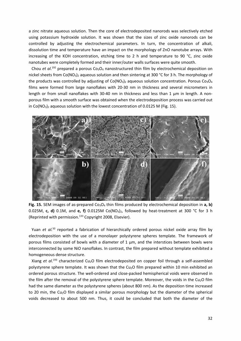
32
a zinc nitrate aqueous solution. Then the core of electrodeposited nanorods was selectively etched using potassium hydroxide solution. It was shown that the sizes of zinc oxide nanorods can be controlled by adjusting the electrochemical parameters. In turn, the concentration of alkali, dissolution time and temperature have an impact on the morphology of ZnO nanotube arrays. With increasing of the KOH concentration, etching time to 2 h and temperature to 90 °C, zinc oxide nanotubes were completely formed and their inner/outer walls surfaces were quite smooth.
Chou et al.192 prepared a porous Co3O4 nanostructured thin film by electrochemical deposition on nickel sheets from Co(NO3)2 aqueous solution and then sintering at 300 °C for 3 h. The morphology of the products was controlled by adjusting of Co(NO3)2 aqueous solution concentration. Porous Co3O4 films were formed from large nanoflakes with 20-30 nm in thickness and several micrometers in length or from small nanoflakes with 30-40 nm in thickness and less than 1 µm in length. A non-porous film with a smooth surface was obtained when the electrodeposition process was carried out in Co(NO3)2 aqueous solution with the lowest concentration of 0.0125 M (Fig. 15).
Fig. 15. SEM images of as-prepared Co3O4 thin films produced by electrochemical deposition in a, b) 0.025M, c, d) 0.1M, and e, f) 0.0125M Co(NO3)2, followed by heat-treatment at 300 °C for 3 h (Reprinted with permission.133 Copyright 2008, Elsevier).
Yuan et al.50 reported a fabrication of hierarchically ordered porous nickel oxide array film by
electrodeposition with the use of a monolayer polystyrene spheres template. The framework of porous films consisted of bowls with a diameter of 1 μm, and the interstices between bowls were interconnected by some NiO nanoflakes. In contrast, the film prepared without template exhibited a homogeneous dense structure.
Xiang et al.193 characterized Cu2O film electrodeposited on copper foil through a self-assembled polystyrene sphere template. It was shown that the Cu2O film prepared within 10 min exhibited an ordered porous structure. The well-ordered and close-packed hemispherical voids were observed in the film after the removal of the polystyrene sphere template. Moreover, the voids in the Cu2O film had the same diameter as the polystyrene spheres (about 800 nm). As the deposition time increased to 20 min, the Cu2O film displayed a similar porous morphology but the diameter of the spherical voids decreased to about 500 nm. Thus, it could be concluded that both the diameter of the
33
polystyrene spheres and the electrodeposition time had an impact on the geometry of the voids in the Cu2O film.
3.2.9. Biogenic synthesis In recent years, the biogenic synthesis of MO nanostructures using microorganisms or plant extracts have been of great interest to many scientists from around the world due to its cost-effectiveness, safety, versatility, mild conditions, and high production yield.194, 195 Moreover, this approach is environmentally friendly and allows to reduce or eliminate the use of toxic reaction precursors and solvents. In the synthetic procedure bacteria, fungi, yeast, and plant extracts act as reducing or stabilizing agents. The size of the nanostructures can be controlled by adjusting reaction parameters including temperature, time, pH of the solution and the concentration of reactants. The morphology of the nanoparticles can be modulated by a selection of appropriate microorganisms or plant extracts.194, 195 Biogenic methods have been developed to prepare many MOs including TiO2,196, 197 UO2,198 ZnO,195, 199-204Fe3O4,205-207 CuO208, 209.
Zhou et al.196 synthesized biomorphic TiO2 hollow spheres and tubes using two species of bacteria - Streptococcus thermophilus and Lactobacillus bulgaricus as biotemplates naturally covered with different organic functional groups (e.g. carboxyl, ester, amine, hydroxyl groups) which can easily capture cations. The original morphologies of bacteria were retained in the case of titania structures. TiO2 hollow spheres obtained applying Streptococcus thermophilus had a diameter of 500 nm and shell thickness of about 15 nm. It was observed that during calcination at 700 °C some spheres were broken demonstrating their hollow cavities. A rod-shaped Lactobacillus bulgaricus was a template in the synthesis of TiO2 hollow tubes having a diameter in the range 200-300 nm and length of 800 nm. The shell thickness was measured to be 30-40 nm. Jha et al.139 reported the preparation of spherical titania particles assisted with Lactobacillus sp. and baker's yeast (S. cerevisiae). The nanoparticles showed broad size distributions with average diameters of 25 or 12.5 nm for TiO2 synthesized in the presence of bacterium and yeast, respectively. The duration of the reaction strongly affected the size disztribution of the nanoparticles.
Suzuki et al.198 described a fabrication of UO2 nanoparticles from uranium in sediments by reduction with Desulfosporosinus spp., a Gram-positive sulphate-reducing microbe. The uranite nanoparticles were spherical and less than 3 nm in diameter. They occurred as specific aggregates and particle coatings on the bacterial cell surface.
In recent years, many studies have been focused on the biological methods of ZnO nanostructures fabrication employing plant extracts, bacterial strains or fungi. Ali et al.199 applied Aloe barbadensis Miller leaf extract with high reducing and capping potential for the biogenic synthesis of zinc oxide nanoparticles of different morphology. ZnSO4 was adopted as a precursor in the synthetic procedure. The ZnO nanoparticles with size varied from 8 to 18 nm showed spherical, oval and hexagonal shapes. Rajiv et al.200 obtained highly stable, spherical and hexagonal ZnO nanoparticles with an antifungal activity employing Parthenium hysterophorus L. leaf extract. Their morphology was dependent on the concentration of the plant extract. The spherical and hexagonal nanoparticles were not uniform and had an average size of about 27 and 84 nm, respectively. Nagajyothi et al.143 demonstrated an eco-friendly and inexpensive approach for the formation of zinc oxide nanoparticles from Coptidis Rhizoma which is the dried rhizome of Coptis chinensis Franch.201 It was observed that ZnO nanoparticles with the size ranged from 3 to 25 nm were nearly spherical or rod-like shaped. Madan et al.202 reported facile biosynthesis of ZnO nanostructures with diverse shapes performed via low-temperature solution combustion using neem (Azadirachta indica) extract. It was
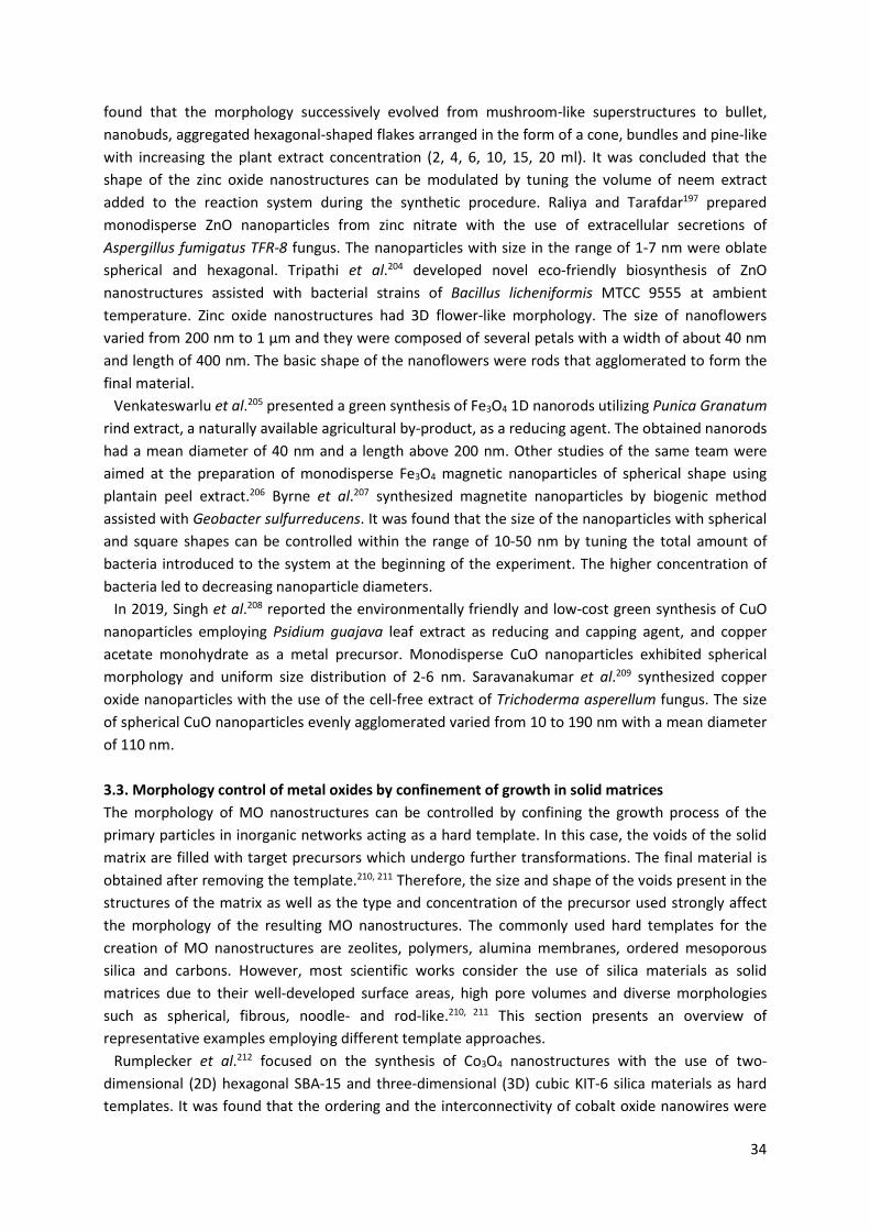
34
found that the morphology successively evolved from mushroom-like superstructures to bullet, nanobuds, aggregated hexagonal-shaped flakes arranged in the form of a cone, bundles and pine-like with increasing the plant extract concentration (2, 4, 6, 10, 15, 20 ml). It was concluded that the shape of the zinc oxide nanostructures can be modulated by tuning the volume of neem extract added to the reaction system during the synthetic procedure. Raliya and Tarafdar197 prepared monodisperse ZnO nanoparticles from zinc nitrate with the use of extracellular secretions of Aspergillus fumigatus TFR-8 fungus. The nanoparticles with size in the range of 1-7 nm were oblate spherical and hexagonal. Tripathi et al.204 developed novel eco-friendly biosynthesis of ZnO nanostructures assisted with bacterial strains of Bacillus licheniformis MTCC 9555 at ambient temperature. Zinc oxide nanostructures had 3D flower-like morphology. The size of nanoflowers varied from 200 nm to 1 µm and they were composed of several petals with a width of about 40 nm and length of 400 nm. The basic shape of the nanoflowers were rods that agglomerated to form the final material.
Venkateswarlu et al.205 presented a green synthesis of Fe3O4 1D nanorods utilizing Punica Granatum rind extract, a naturally available agricultural by-product, as a reducing agent. The obtained nanorods had a mean diameter of 40 nm and a length above 200 nm. Other studies of the same team were aimed at the preparation of monodisperse Fe3O4 magnetic nanoparticles of spherical shape using plantain peel extract.206 Byrne et al.207 synthesized magnetite nanoparticles by biogenic method assisted with Geobacter sulfurreducens. It was found that the size of the nanoparticles with spherical and square shapes can be controlled within the range of 10-50 nm by tuning the total amount of bacteria introduced to the system at the beginning of the experiment. The higher concentration of bacteria led to decreasing nanoparticle diameters.
In 2019, Singh et al.208 reported the environmentally friendly and low-cost green synthesis of CuO nanoparticles employing Psidium guajava leaf extract as reducing and capping agent, and copper acetate monohydrate as a metal precursor. Monodisperse CuO nanoparticles exhibited spherical morphology and uniform size distribution of 2-6 nm. Saravanakumar et al.209 synthesized copper oxide nanoparticles with the use of the cell-free extract of Trichoderma asperellum fungus. The size of spherical CuO nanoparticles evenly agglomerated varied from 10 to 190 nm with a mean diameter of 110 nm. 3.3. Morphology control of metal oxides by confinement of growth in solid matrices The morphology of MO nanostructures can be controlled by confining the growth process of the primary particles in inorganic networks acting as a hard template. In this case, the voids of the solid matrix are filled with target precursors which undergo further transformations. The final material is obtained after removing the template.210, 211 Therefore, the size and shape of the voids present in the structures of the matrix as well as the type and concentration of the precursor used strongly affect the morphology of the resulting MO nanostructures. The commonly used hard templates for the creation of MO nanostructures are zeolites, polymers, alumina membranes, ordered mesoporous silica and carbons. However, most scientific works consider the use of silica materials as solid matrices due to their well-developed surface areas, high pore volumes and diverse morphologies such as spherical, fibrous, noodle- and rod-like.210, 211 This section presents an overview of representative examples employing different template approaches.
Rumplecker et al.212 focused on the synthesis of Co3O4 nanostructures with the use of two-dimensional (2D) hexagonal SBA-15 and three-dimensional (3D) cubic KIT-6 silica materials as hard templates. It was found that the ordering and the interconnectivity of cobalt oxide nanowires were
35
strongly determined by the amount of mesoporous silica added into the solution of Co(NO3)2·6H2O precursor during the synthetic procedure. When the loading of the solid matrix increased the nanostructures changed from randomly packed, isolated Co3O4 nanowires to highly ordered, mesostructured, and fully interconnected networks. Moreover, the application of cubic KIT-6 silica with specific wall thickness and degree of framework interconnectivity as a template allowed to modulate the pore size of mesostructured Co3O4 from 3 nm up to 10 nm.
Lakshmi et al.213 reported a general preparation of semiconductor MO nanotubes and fibrils via the sol-gel method applying porous alumina and polymeric filter membranes as templates. For TiO2 nanostructures, the synthetic procedure involved dipping of alumina membrane in a TiO2 sol obtained by mixing solution of titanium isopropoxide with water, ethanol and hydrochloric acid followed by drying, heating at 400 °C for 24 h and removal of the template. The results have shown that titania tubules were formed when the alumina membrane was immersed in the sol for only 5 s, while solid TiO2 fibrils were obtained within 60 s. Immersion of template for 25 s led to producing tubules with very thick walls. In all cases, the outside diameter of tubules and fibrils was about 200 nm (the diameter of the pores in the template) and a length of 50 µm (the thickness of the alumina membrane). The morphology of the TiO2 nanostructures was also controlled by the temperature of the membrane dipping process. Thin-walled TiO2 tubules and fibrils were fabricated at 5 °C and 20 °C, respectively. Similar methods were applied for the synthesis of 1D nanostructures of other MOs such as MnO2, V2O5, Co3O4, ZnO, and WO3. Limmer et al.214 demonstrated the template-based growth of uniform oxides nanorods (TiO2, SiO2, BaTiO3, Sr2Nb2O7, and Pb(Zr0.52Ti0.48)O3), formed by a combination of the sol-gel process and electrophoretic deposition. These nanostructures with a diameter in the range 125-200 nm and length of 10 µm were arranged parallel to one another over a broad area of the hydrophilic polycarbonate (PC) membrane.
The hard templating method is widely applied to obtain hollow spheres.215 The size of the inner hollow space can be modulated by a selection of appropriate solid matrix whereas the thickness of the shell by adjusting the concentration of the reactants and changing hydrophilicity of the template surface. Ren et al.216 described a synthesis of uniform hollow titania nanospheres with an average diameter of approximately 80 nm and composed of 7 nm-sized nanoparticles employing quasi-nanosized carbonaceous spheres. Zeng et al.217 also reported a simple hard template strategy for the fabrication of multi-shelled TiO2 structures with the use of porous polystyrene-divinylbenzene (PS-DVB) spheres as templates. The TiO2 spheres had smooth surfaces and were connected with each other. It should be noted that the application of the solid matrix does not always limit the final shape of the product to hollow spheres.215
In recent years, a lot of consideration has been paid to the application of metal-organic frameworks (MOFs) both as precursors and self-sacrificial templates in the fabrication of MO nanostructures with diverse compositions and morphologies.218 The advantages of MOFs are the tunability of structural and chemical function, the well-developed specific surface area, high porosity, good structural integrity, and various physicochemical properties.5, 6, 8, 219, 220 When MOFs are subjected to direct annealing in an oxygen atmosphere, the organic linkers decompose creating pores whereas metal ions oxidize to metal oxides.218
Zhang et al.221 described a simple approach to synthesize Co3O4 polyhedrons and plates via the calcination of two metal formate frameworks (MFFs) with different morphologies. It was shown that the obtained Co3O4 samples not only inherited the original shapes of the as-prepared precursors but also were composed of many interconnected nanoparticles. In other studies, Zhao et al.222 revealed
36
that Co3O4 nanostructures retained the rhombic dodecahedral morphology of the ZIF-63 template after thermal treatment at 350 °C for 2 h in air.
Wu et al.223 synthesized porous CuO hollow architectures with octahedral shape by annealing Cu-based metal-organic framework ([Cu3(btc)2], btc - benzene-1,3,5-tricarboxylate) templates. It was found that the morphology of the CuO products can be controlled by changing thermal treatment conditions of [Cu3(btc)2]. When the calcination process was performed at 300 °C, the octahedral shape of the MOF template was well preserved in CuO samples. Moreover, their surface was very rough and contained many holes demonstrating the formation of pores. During calcination at a temperature of 350 °C, some initial octahedra collapsed creating flower-like CuO structures whereas at 400 °C only agglomerates with non-regular shapes were obtained. In 2015, Song et al.224 published a very interesting paper about a green strategy to fabricate CuO superstructures in which octahedral and six-prismatic Cu-MOFs prepared by the hydrothermal method were only immersed and stirred in NaOH solution without further thermal treatment. Novel 3D urchin-like and rod-like CuO superstructures consisted of nanoparticles, nanowires, and nanosheets (Fig. 16). The inner structure of MOFs strongly determined the morphology of hierarchical structures of the prepared CuO.
Fig. 16. SEM images of urchin-like CuO superstructures prepared by immersing octahedral Cu-MOFs in 0.1M NaOH at room temperature for a) 5 h or b) 12 h and SEM images of rod-like CuO superstructures obtained by immersing six-prismatic Cu-MOFs in 0.1M NaOH for c) 30 min or d) 5 h (Licensed under CC-BY.224).
Zhang et al.225 prepared NiO nano/microstructures employing a facile solid-state thermolysis of Ni-
based MOF precursor obtained via a solvothermal method from p-benzene-dicarboxylic acid (bdc) and NiCl2·6H2O. Nickel oxide samples were composed of porous two-dimensional sheets formed from many uniform nanoparticles. It was observed that temperature and time of the thermolysis had significant impact on the structure and morphology of the products.
37
4. MO-to-MOF morphology control
Structural designability at the molecular length scale, feasibility of chemical functionalization and accessible high surface area of MOFs are the main reasons they are still intensively studied materials. The wide variety of components, i.e., metallic cations and organic linkers, introduces immense possibilities of constructing new types of crystalline scaffolds with desired features. It allows applying MOFs in different fields, such as adsorption,226-231 catalysis,232, 233 separation228, 234-237 or even chemical sensing238-242 and drug delivery243-250.
Although plenty of reports have described the preparation of MOF-derived materials with variety of composition and morphology, there are less syntheses that are focused on morphology control of MOFs exclusively.251-256 It is difficult to predict in what kind of shape and size the MOF nanomaterial will be obtained, even if the topology of a single MOF unit is predicted, especially after one MOF topology can crystallize in various different structures.257 In addition, the term `morphology control` is usually used in a misleading way when any homogeneous particles with definable forms are synthesized. In fact, `morphology control` should be used for well-thought out strategies, of which purpose precisely leads to beforehand selected shape and size of the product. It is extremely difficult to achieve this kind of control, especially for structures such as aesthetically captivating and extraordinarily complex. The starting point for `morphology control` is the deep understanding of the involved chemical reactions on a molecular level; only when one is able to gain control over the underlying chemistry it is also possible to really control and dictate the material’s morphology. The construction of MOFs usually starts with the strategic selection of precursor materials: inorganic building units (IBUs), which are mostly formed in situ from a metal precursor, and organic building units (OBUs), which are commonly polytopic acids or imidazoles. To coordinate ligands to a metal centre and form the IBU, it is necessary to use substrates that provide easily accessible metallic cations. For that, the most common ion sources used are metal salts (e.g. nitrates, chlorides), as they easily dissolve in solvent. While this straightforward dissolution often favours MOF nucleation and growth, morphology is mainly dictated by the underlying MOF topology. Strategic pathways, such as top-down synthesis and controlled SBU approaches allow to control these topologies, however they fail to deliberately obtain complex 3-dimensional structures. In contrast, the MO precursor strategy might seem challenging due to low solubility of MOs caused by high lattice enthalpies, however, it has substantial advantages that metal salts cannot provide (Table 2).257 Firstly, MOs can serve as substructures and templates for the final MOF, differently from metal salts, which dissolve far too easily due to the comparably high solubility. While aggressive reaction conditions facilitating MO dissolution bear similar initial reaction conditions, careful optimizations of the experimental conditions allow to preserve the MO morphology during the MO-to-MOF conversion. Thoroughly balancing of simultaneous MO dissolution and MOF formation enables to take advantage of the comparatively stable MO shape and morphology with it serving as self-sacrificial template. Furthermore, many available deposition and patterning techniques grant endless possibilities of diverse 3-dimensional MO structures, extending the variety of new MOF morphologies.
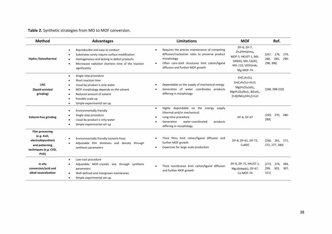
38
Table 2. Synthetic strategies from MO to MOF conversion.
Method Advantages Limitations MOF Ref.
Hydro-/Solvothermal
x Reproducible and easy to conduct x Substrates rarely require surface modification x Homogeneous and lacking in defect products x Microwave radiation shortens time of the reaction
significantly
x Requires the precise maintenance of competing diffusion/nucleation rates to preserve product morphology
x Often core-shell structures limit cation/ligand diffusion and further MOF growth
ZIF-8, ZIF-7, Zn4(Him)(Im)8,
MOF-5, HKUST-1, MIL-100(Al), MIL-53(Al), MIL-110, V(OH)ndc,
Mg-MOF-74
[267, 276, 279, 280, 283, 290-298, 306]
LAG (liquid-assisted
grinding)
x Single-step procedure x Short reaction time x Usual by-product is only water x MOF morphology depends on the solvent x Reduced amount of solvent x Possible scale-up x Simple experimental set-up
x Dependable on the supply of mechanical energy x Generation of water coordinates products
differing in morphology
Zn(C4H2O4), Zn(C4H2O4)·nH2O, Mg(H2O)4(sal)2,
Mg(H2O)6(ibu)2, Bi(sal)n, [Cd](INA)2(OH2)]·H2O
[268, 308-310]
Solvent-free grinding
x Environmentally friendly x Single-step procedure x Usual by-product is only water x Simple experimental set-up
x Highly dependable on the energy supply (thermal and/or mechanical)
x Long-time procedure x Generation water-coordinated products
differing in morphology
ZIF-8, ZIF-67 [269, 270, 286-289]
Film processing (e.g. ALD,
electrodeposition) and patterning
techniques (e.g. CVD, PVD)
x Environmentally friendly (solvent-free) x Adjustable film thickness and density through
synthesis parameters
x Thick films limit cation/ligand diffusion and further MOF growth
x Expensive for large-scale production
ZIF-8, ZIF-61, ZIF-72, CuBDC
[260, 261, 271, 272, 277, 280]
In situ conversion/acid and alkali neutralization
x Low-cost procedure x Adjustable MOF-crystals size through synthesis
parameters x Well-defined and intergrown membranes x Simple experimental set-up
x Thick membranes limit cation/ligand diffusion and further MOF growth
ZIF-8, ZIF-71, HKUST-1, Mg2(dobpdc), ZIF-67,
Co-MOF-74
[273, 274, 284, 299, 303, 307, 311]
39
4.1. Mechanism MO-to-MOF conversion rates are subjected to MO composition, morphology (shape and size), surface roughness and pH-dependent surface charge.257-259 Tuning these MO features enables fabrication of materials with desirable MOF structures, without the need for surface functionalizations like self-assembled monolayers (SAMs).260, 261 For example, it was found that the formation of Cu3(BTC)2 (known as HKUST-1) from CuO sheets is easily feasible, whereas no HKUST-1 was obtained when CuO microcrystals were used under the same conditions.258 Moreover, choosing suitable solvent(s) in solution-based syntheses is as important for the final MOF morphology as selection of proper MO nanoparticle shape and size. This is exemplified for ZnO, with mixtures of octanol and 2-methylimidazole (2-mim or Hmim) not resulting in ZIF-8 formation, whilst ethanol addition amplified MO dissolution and allowed MOF growth.262 To fully use the advantages of MOs, a good understanding of the reaction kinetics as a crucial variable of MO-to-MOF conversions is important. Hence, to enable targeted and controllable synthesis relations among competing rates are the key for which mechanism dominates: dissolution-crystallization or template-assisted transition, where the latter is instrumental for a controlled MO-to-MOF conversion (Fig. 17).
The rates that govern MO-to-MOF conversion are MO dissolution, metallic cations/ligands diffusion, MOF nucleation, and MOF growth. High MO dissolution rates paired with sufficient diffusion can result in random crystallization within the solution associated to local supersaturations (homogeneous nucleation).259 In this case, particles grow in the solution without templating effect, working similarly to soluble salts but without accompanying acidic by-products. On the other hand, when the MO dissolution is balanced in a way, that MOF nucleation can occur locally around the substrate (heterogeneous nucleation) without too high diffusion rates, the MO can serve as a self-sacrificial template. This shape preserving mechanism can allow the full transformation of the MO substrate into MOF and hence the perpetuation of the original morphology. The progressive metallic cation-release as a result of the MO dissolution causes a concentration gradient of IBUs from the substrate to the solution, allowing the MOF to maintain on the MO and eventually to entirely replace it. However, to obtain full conversion, rates have to be matched perfectly and most often the result of MO-to-MOF reactions are core-shell-like structures explainable by diffusion limitations as a result of a closed MOF shell around the substrates before total transformation. Accordingly, to receive the entire conversion or a desired core-shell structure respectively, each reaction requires the understanding of the effect of the different reaction parameters on the system as well as the choice of a suitable MO morphology.
It is important to point out that the physicochemical properties of MOFs depend on their nanostructure, which is not observed for bulk-materials.245, 263 Thus, designing the right route for MOF assembly is a matter of relevance for scaffolding features and application. Reaction conditions and their impact on kinetics vary dependent on the chosen method. Regardless, there is a general aspect for so-called structured-directing agents (SDA) including guest molecules, mineralizers, surfactants and swelling agents.264 Whereas solvent-free reactions for MOF self-assembly are feasible, it is challenging to fabricate uniform and distinguished MOF nanomaterials that way. For most commonly used solvent-based syntheses main concern is a choice of solvent(s), solvent ratio, precursor concentration ratio and reaction times. All of these factors can be used effectively if the proper temperature during the processes is applied, as well as enhancements such as radiation, sonication or electric field.
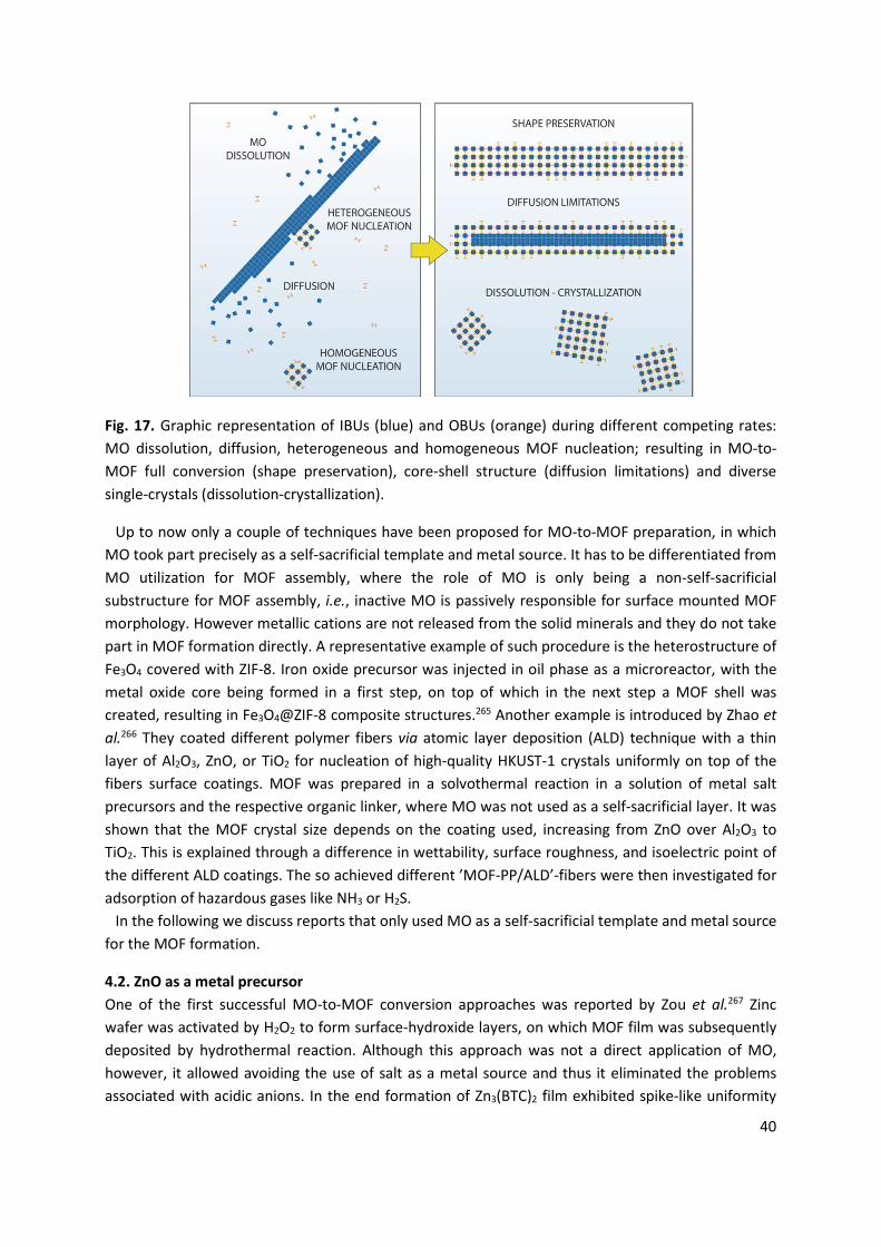
40
Fig. 17. Graphic representation of IBUs (blue) and OBUs (orange) during different competing rates: MO dissolution, diffusion, heterogeneous and homogeneous MOF nucleation; resulting in MO-to-MOF full conversion (shape preservation), core-shell structure (diffusion limitations) and diverse single-crystals (dissolution-crystallization).
Up to now only a couple of techniques have been proposed for MO-to-MOF preparation, in which MO took part precisely as a self-sacrificial template and metal source. It has to be differentiated from MO utilization for MOF assembly, where the role of MO is only being a non-self-sacrificial substructure for MOF assembly, i.e., inactive MO is passively responsible for surface mounted MOF morphology. However metallic cations are not released from the solid minerals and they do not take part in MOF formation directly. A representative example of such procedure is the heterostructure of Fe3O4 covered with ZIF-8. Iron oxide precursor was injected in oil phase as a microreactor, with the metal oxide core being formed in a first step, on top of which in the next step a MOF shell was created, resulting in Fe3O4@ZIF-8 composite structures.265 Another example is introduced by Zhao et al.266 They coated different polymer fibers via atomic layer deposition (ALD) technique with a thin layer of Al2O3, ZnO, or TiO2 for nucleation of high-quality HKUST-1 crystals uniformly on top of the fibers surface coatings. MOF was prepared in a solvothermal reaction in a solution of metal salt precursors and the respective organic linker, where MO was not used as a self-sacrificial layer. It was shown that the MOF crystal size depends on the coating used, increasing from ZnO over Al2O3 to TiO2. This is explained through a difference in wettability, surface roughness, and isoelectric point of the different ALD coatings. The so achieved different ’MOF-PP/ALD’-fibers were then investigated for adsorption of hazardous gases like NH3 or H2S.
In the following we discuss reports that only used MO as a self-sacrificial template and metal source for the MOF formation.
4.2. ZnO as a metal precursor One of the first successful MO-to-MOF conversion approaches was reported by Zou et al.267 Zinc wafer was activated by H2O2 to form surface-hydroxide layers, on which MOF film was subsequently deposited by hydrothermal reaction. Although this approach was not a direct application of MO, however, it allowed avoiding the use of salt as a metal source and thus it eliminated the problems associated with acidic anions. In the end formation of Zn3(BTC)2 film exhibited spike-like uniformity
41
with large scale orders. In the same year Friščić et al.268 used specifically MOs as precursors due to their low-cost and availability. In the single-step neutralisation of MOs with dicarboxylic acids MOF structure was formed, with water as a sole by-product. Their approach based on ZnO and fumaric acid in a liquid-assisted grinding (LAG) reaction led to the formation of the materials varied in morphology by using different grinding liquids i.e. ethanol (3D MOF), mixture of ethanol and water with molar ratio 1:1 (2D MOF) and various amount of water (1D zigzag or linear polymers). Interestingly, Lin et al.269 presented formation of ZIF-8 (in their article described as MAF-4) by solvent-free grinding of ZnO or Zn(OH)2. At room temperature substrates did not react, however, after heating at 100 °C for 24 h ZIF-8 was obtained. It was possible to shorten the reaction time to 12 h by heating up the mixture to 180 °C. Powder X-ray diffraction indicated that increasing temperature resulted in sharper and weaker reflexes, which are typical for the guest-free ZIF-8 structure. This method allowed fabrication of high purity ZIF with 100% yield, specific surface area of 1450 m2 g-1 and with relatively homogenous sub-micrometer crystals. In further reports MOFs with higher surface area such as Zn(mim)2 (1961 m2 g-1) and new Co(mim)2 (2070 m2 g-1) were also prepared.270 Zn and Co imidazoles were obtained in direct acid-base reaction between ZnO/CoO/Co(OH)2. Synthesized ZIF network topologies revealed dependency on the presence of small amounts of co-solvents such as 1-butanol, pyridine or 4-methylpyridine, as well as on the heating rate. Addition of a third species can lower the topological density leading to open-framework compounds. In the case of temperature, the increase enhances ligands deprotonation, which directly leads to homoleptic complexes formation. Heating rate, however, if kept slow provides higher crystallinity of Zn- and Co-derived MOFs, as well as larger size of crystallites.
Stassen et al.260 also focused on ZnO with the aim of the transformation of the resulting two- and three-dimensional MO patterns to ZIF-8 pattern by a convenient two-step procedure via sputtering or electrochemical growth, respectively. It was conducted through green solvent-free reaction of ZnO precursor films and patterns with melted organic linker (Hmim). Variation of film thickness and density allowed the control of the ZIF-8 crystal size due to the change of Zn2+ supply. In a follow up work uniform ZnO thin films of precisely controlled thickness were deposited using ALD technology, both on a flat substrate and high-aspect-ratio features, which then have been transformed into ZIF-8 using chemical vapour deposition (CVD), providing the linker as a vapour instead of a solution.271 Different from CVD method, solvothermal transformations need precise matching of MO dissolution and MOF crystallization rates, as slight local differences in dissolution rate, coupled with fast diffusion of the released metal ions can lead to the formation of rough films with many defects. Cross-sectional analysis via TEM allowed the study of the MO-to-MOF conversion efficiency: complete transformation could be observed for precursor films of less than 10 nm thickness. Thicker films do not show full transformation because of the diffusion limitations of the organic linker to the oxide and/or of zinc to the growing crystal interface. However, the expansion of around 10 nm film thickness is expected due to the fabrication of highly porous ZIF-8 from the dense ZnO. The thickness increase indicated linkage accordingly to the theoretical value based on the ratio of the crystallographic volume occupied per mol of zinc in MO and MOF.
To show the general applicability of the MOF-CVD approach, ZIF-61 (imidazole) and ZIF-72 (4,5-dichloroimidazole), the Co-based ZIF-67 (using CoO films and Hmim) were deposited under similar experimental conditions, as well as Cu(II)-dicarboxylates using copper hydroxide films as precursor film and fumaric acid and 1,4-H2BDC as organic linker.272 A different approach for obtaining ZIF-8 membranes was suggested by Li et al.273 from Zn(OH)2 nanostrands. It is liquid-based synthesis in
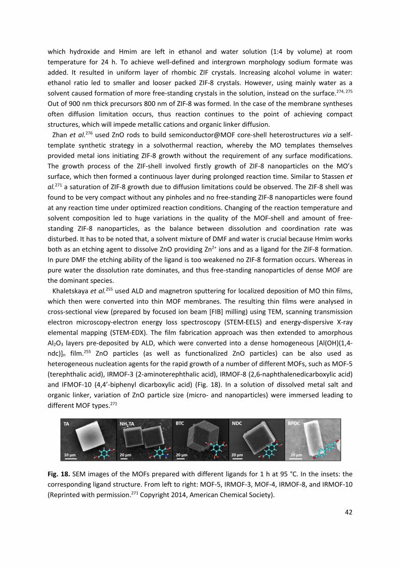
42
which hydroxide and Hmim are left in ethanol and water solution (1:4 by volume) at room temperature for 24 h. To achieve well-defined and intergrown morphology sodium formate was added. It resulted in uniform layer of rhombic ZIF crystals. Increasing alcohol volume in water: ethanol ratio led to smaller and looser packed ZIF-8 crystals. However, using mainly water as a solvent caused formation of more free-standing crystals in the solution, instead on the surface.274, 275 Out of 900 nm thick precursors 800 nm of ZIF-8 was formed. In the case of the membrane syntheses often diffusion limitation occurs, thus reaction continues to the point of achieving compact structures, which will impede metallic cations and organic linker diffusion.
Zhan et al.276 used ZnO rods to build semiconductor@MOF core-shell heterostructures via a self-template synthetic strategy in a solvothermal reaction, whereby the MO templates themselves provided metal ions initiating ZIF-8 growth without the requirement of any surface modifications. The growth process of the ZIF-shell involved firstly growth of ZIF-8 nanoparticles on the MO’s surface, which then formed a continuous layer during prolonged reaction time. Similar to Stassen et al.271 a saturation of ZIF-8 growth due to diffusion limitations could be observed. The ZIF-8 shell was found to be very compact without any pinholes and no free-standing ZIF-8 nanoparticles were found at any reaction time under optimized reaction conditions. Changing of the reaction temperature and solvent composition led to huge variations in the quality of the MOF-shell and amount of free-standing ZIF-8 nanoparticles, as the balance between dissolution and coordination rate was disturbed. It has to be noted that, a solvent mixture of DMF and water is crucial because Hmim works both as an etching agent to dissolve ZnO providing Zn2+ ions and as a ligand for the ZIF-8 formation. In pure DMF the etching ability of the ligand is too weakened no ZIF-8 formation occurs. Whereas in pure water the dissolution rate dominates, and thus free-standing nanoparticles of dense MOF are the dominant species.
Khaletskaya et al.255 used ALD and magnetron sputtering for localized deposition of MO thin films, which then were converted into thin MOF membranes. The resulting thin films were analysed in cross-sectional view (prepared by focused ion beam [FIB] milling) using TEM, scanning transmission electron microscopy-electron energy loss spectroscopy (STEM-EELS) and energy-dispersive X-ray elemental mapping (STEM-EDX). The film fabrication approach was then extended to amorphous Al2O3 layers pre-deposited by ALD, which were converted into a dense homogeneous [Al(OH)(1,4-ndc)]n film.255 ZnO particles (as well as functionalized ZnO particles) can be also used as heterogeneous nucleation agents for the rapid growth of a number of different MOFs, such as MOF-5 (terephthalic acid), IRMOF-3 (2-aminoterephthalic acid), IRMOF-8 (2,6-naphthalenedicarboxylic acid) and IFMOF-10 (4,4’-biphenyl dicarboxylic acid) (Fig. 18). In a solution of dissolved metal salt and organic linker, variation of ZnO particle size (micro- and nanoparticles) were immersed leading to different MOF types.271
Fig. 18. SEM images of the MOFs prepared with different ligands for 1 h at 95 °C. In the insets: the corresponding ligand structure. From left to right: MOF-5, IRMOF-3, MOF-4, IRMOF-8, and IRMOF-10 (Reprinted with permission.271 Copyright 2014, American Chemical Society).
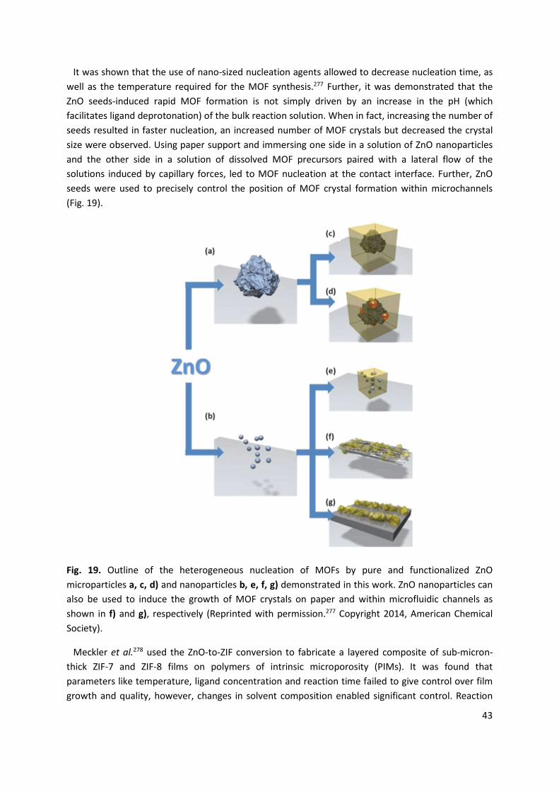
43
It was shown that the use of nano-sized nucleation agents allowed to decrease nucleation time, as well as the temperature required for the MOF synthesis.277 Further, it was demonstrated that the ZnO seeds-induced rapid MOF formation is not simply driven by an increase in the pH (which facilitates ligand deprotonation) of the bulk reaction solution. When in fact, increasing the number of seeds resulted in faster nucleation, an increased number of MOF crystals but decreased the crystal size were observed. Using paper support and immersing one side in a solution of ZnO nanoparticles and the other side in a solution of dissolved MOF precursors paired with a lateral flow of the solutions induced by capillary forces, led to MOF nucleation at the contact interface. Further, ZnO seeds were used to precisely control the position of MOF crystal formation within microchannels (Fig. 19).
Fig. 19. Outline of the heterogeneous nucleation of MOFs by pure and functionalized ZnO microparticles a, c, d) and nanoparticles b, e, f, g) demonstrated in this work. ZnO nanoparticles can also be used to induce the growth of MOF crystals on paper and within microfluidic channels as shown in f) and g), respectively (Reprinted with permission.277 Copyright 2014, American Chemical Society).
Meckler et al.278 used the ZnO-to-ZIF conversion to fabricate a layered composite of sub-micron-thick ZIF-7 and ZIF-8 films on polymers of intrinsic microporosity (PIMs). It was found that parameters like temperature, ligand concentration and reaction time failed to give control over film growth and quality, however, changes in solvent composition enabled significant control. Reaction
44
mixtures of DMF-to-water with up to 50 vol % water yielded relatively smooth and continuous ZIF-8 films, suggesting the formation of many ZIF-8 nuclei and comparatively slow crystal growth. At water content beyond 50 vol %, significantly less ZnO was visible in cross-sectional SEM images and the ZIF-8 grain size increased, resulting in faceted, isolated crystals adhered to the polymer surface instead of a continuous film. Uninterrupted, nearly pure ZIF-8 coatings could be obtained from 15 nm thick ZnO films with 50 vol % water reaction mixtures. Variant preparation of substructure for ZIF-8 was suggested by Al-Kutubi et al.279 They synthesized ZIF-8 thin films on top of an electrochemically grown ZnO rod array. They were fabricated through the deposition of the linker on top of the rod array, with subsequent solvent evaporation to form a thin uniform linker film. Heating the sample in an oven resulted in the formation of a ZIF-8 film on the ZnO arrays. Liu et al.280 prepared a ZIF-8-ZnAl-NO3 layered double hydroxide (LDH) composite membrane by partial conversion of the ZnAl-NO3 LDH membrane in a one-step reaction for enhanced H2/CH4 separation. Zhang and coworkers281 converted ZnO to ZIF-8 as precursors/sacrificial template to construct Zn-based nanoarchitecture electrode materials for high energy storage lithium-ion batteries. ZIF-8 was thereby transformed into amorphous carbon framework and ZnO quantum dots in a thermal decomposition process. Del Rio et al.282 used a sacrificial ZnO coating which is transformed into ZIF-8 to create polystyrene–ZnO–ZIF-8 core–double-shell particles with an intermediate shell of residual ZnO. Increasing reaction time and temperature did not show any influence on ZnO conversion into ZIF-8, suggests interrupted growth due to the diffusion limitations after a certain point. Maserati and coworkers252 studied the formation of M-MOF-74 series (M2(dobpdc), M = Mg, Mn, Co, Ni, Zn) using different bivalent MOs as precursors in a solvothermal reaction, following a dissolution-crystallization mechanism, with the MO dissolution being the rate-limiting factor.258 The use of MOs as precursors allowed them to reduce reaction times by several orders of magnitude, achieving MOF formation in a matter of minutes.
Sun et al.283 reported the formation of Zn-derived MOF shells: ZIF-8 and ZIF-71 on ZnO particles as cores, reacting with Hmim and 4,5-dichloroimidazole, respectively. To prevent aggregation of minerals their surfaces were modified with PVP, which additionally promoted retention of the released metallic cations near the template. Three types of colloidal ZnO particles with different size were fabricated: 95 nm, 230 nm and 320 nm. Synthesized MOF product from 95 nm ZnO showed rhombic-dodecahedral shape with 270 nm diameter. TEM and TGA revealed that ZnO remains inside the structure, with 12.8 wt.% of non-converted oxide. It was caused by the small pore apertures present in ZIF, resulting in before mentioned Zn2+ diffusion limitations. The sizes of ZnO@ZIF core-shell particles were dependent on the template size, diffusion and nucleation/growth rates, which mainly were influenced by the ratio of water/DMF. Water enhances ZnO dissolution, whereas DMF reduces it. Both, however, if used separately cause heterogeneous nucleation of MOF nanoislands on the mineral core. Solvent effect was investigated manifesting hybrid core-shell particles in aqueous solution. Changing the thickness of ZIF-8 shell was possible with DMF addition. Treatment of reactants with DMF only led to fabrication of partially enshrouded structures, with one or several MOF domains on the mineral template. Furthermore, limited Zn2+ diffusion slower than nucleation and growth ended up in surrounding the core with thin ZIF layer and thereby further thickening of the shell was terminated. Size-dependent ZIF formation is linked to the nucleation energy-requirements. It was suggested that lower energy is needed for the growth of ZIF-8 on the oxide surface, than its nucleation. Thus smaller ZnO particles form fewer nucleation sites, ending up with more homogeneous shells. In consequence, if ZnO precursor particle is larger, longer distances have to be overcome between nucleated MOF crystallites and Zn2+ from MOF-free sites. Therefore, it is
45
preferable to form more nuclei on the larger core, leading to intergrown crystal domains. Successful approach of combining MOF from MO with different type of material was introduced by Mazal et al.284 They hybridized MOF-5 and HKUST-1 with polyHIPE by using ZnO and CuO as precursors, respectively. MO nanoparticles embedded into polymer walls formed nanocomposite, which was subjected to organic ligand solution in the solvothermal conditions. TGA and XRD measurements confirmed nearly entire MO-to-MOF conversion into cubic MOF-5 and octahedral HKUST-1. Applying porous polymer without acidic anions stabilized final materials, by avoiding direct exposure of formed MOF crystals to monomeric solution.
There are several proposals of a mechanochemical top-down approach for ZIF-8 synthesis from ZnO grinding with Hmim. Reduction or total solvent absence unlocked novel prospects for prominent composites with MOF. Yue et al.285 synthesized both ZIF-8 nanoparticles and ZIF-8 thin films from the corresponding ZnO nanoscopic precursors through solid-state reactions without the involvement of conventional dissolution processes. According to the authors, this transformation process can be understood as an anion-exchange process, involving the displacement of the lattice oxide anions with imidazolate anions. The dependence of the phase purity on the molar ratios of Hmim to ZnO was shown, e.g. producing phase pure ZIF-8 nanoparticles using a molar ratio of 5:2 (Hmim to ZnO).286 Building upon this work, Yue et al.287 prepared a multi-walled carbon nanotube/zeolitic ZIF-8 composite by a template free ’brick and mortar’ method: ZnO nanoparticles were adsorbed onto the surface of the tubes and then reacted with the organic linker. Strong interactions between linker and the carbon surfaces led to the nucleation and the growth of the ZIF-8 crystal solely on the tube’s surface. ZnO precursor nanoparticles with an average size of 35 nm and no ZnO signal was observed in XRD measurements after the reaction. Involving new materials in milling during MO-to-MOF transition was suggested by Li et al.288 in 2019. They introduced mechanochemistry-assisted solvent-free synthesis involving incorporation of Pd nanoparticles into the MOF structure for catalycic purposes. Using MO/hydroxide without solvents presence is highly preferable for bulk-synthetic industrial routes. Although it seems efficient it is often difficult to synthesize distinguished in morphology MOF nanomaterials via top-down strategies.
4.3. Al2O3 as a metal precursor Besides ZnO another often applied MO for MOF as a substructure and a source of metallic cations is alumina (Al2O3). Reboul et al.289 used Al2O3 in the form of a two-dimensional honeycomb pattern and a three-dimensional inverse opal structure as a metal reservoir and mesoscale SDA for construction of a mesoscopic MOF architecture (namely, coordination replication). [Al(OH)(1,4-ndc)]n was formed in a microwave-assisted reaction in an aqueous solution of the organic linker; MIL-100(Al) in a solution of H3BTC; MIL-53(Al) in a solution of H2BDC. In 2013 Mao et al.290 presented synthesis of oriented three-dimensional MIL-110 rod arrays on porous anodic aluminum oxide membrane (AAO) in the company of the hetero-metal hydroxide strands, which in this case were made of Cu(OH)2. Hexagonal column structure of the MOF was maintained when Cu(OH)2 strand layer was utilized; the absence of such layer led to sheet-like products only. Inductive coupled plasma emission spectrometry (ICP-AES) indicated remaining copper ions in solution after the procedure, thus in the end pure MIL-110 was formed. Also Cd(OH)2 and Zn(OH)2 were tested as SDAs with the successful outcome. Nevertheless, the density of the MIL-110 rods arrays was highly dependent on the kinds of metal hydroxides used. Most dense were rods after Cu(OH)2 application, less after Cd(OH)2 and the least after Zn(OH)2. Another morphology impactful parameter was the time of the reaction.
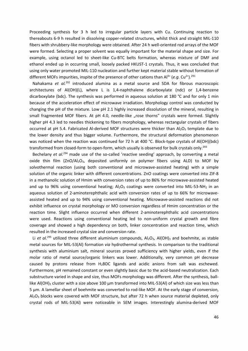
46
Proceeding synthesis for 3 h led to irregular particle layers with Cu. Continuing reaction to thereabouts 6-9 h resulted in dissolving copper-related structures, whilst thick and straight MIL-110 fibers with shrubbery-like morphology were obtained. After 24 h well-oriented rod arrays of the MOF were formed. Selecting a proper solvent was equally important for the material shape and size. For example, using octanol led to sheet-like Cu-BTC belts formation, whereas mixture of DMF and ethanol ended up in occurring small, loosely packed HKUST-1 crystals. Thus, it was concluded that using only water promoted MIL-110 nucleation and further kept material stable without formation of different MOFs impurities, inspite of the presence of other cations than Al3+ (e.g. Cu2+).291
Nahakama et al.292 introduced alumina as a metal source and SDA for fibrous macroscopic architectures of Al(OH)(L), where L is 1,4-naphthalene dicarboxylate (ndc) or 1,4-benzene dicarboxylate (bdc). The synthesis was performed in aqueous solution at 180 °C and for only 1 min because of the acceleration effect of microwave irradiation. Morphology control was conducted by changing the pH of the mixture. Low pH 2.1 highly increased dissolution of the mineral, resulting in small fragmented MOF fibers. At pH 4.0, needle-like „rose thorns” crystals were formed. Slightly higher pH 4.3 led to needles thickening to fibers morphology, whereas rectangular crystals of fibers occurred at pH 5.4. Fabricated Al-derived MOF structures were thicker than Al2O3 template due to the lower density and thus bigger volume. Furthermore, the structural deformation phenomenon was noticed when the reaction was continued for 72 h at 400 °C. Block-type crystals of Al(OH)(bdc) transformed from closed-form to open-form, which usually is observed for bulk crystals only.293
Bechelany et al.294 made use of the so-called ’reactive seeding’ approach, by converting a metal oxide thin film (ZnO/Al2O3, deposited uniformly on polymer fibers using ALD) to MOF by solvothermal reaction (using both conventional and microwave-assisted heating) with a simple solution of the organic linker with different concentrations. ZnO coatings were converted into ZIF-8 in a methanolic solution of Hmim with conversion rates of up to 86% for microwave-assisted heated and up to 96% using conventional heating; Al2O3 coatings were converted into MIL-53-NH2 in an aqueous solution of 2-aminoterephthalic acid with conversion rates of up to 66% for microwave-assisted heated and up to 94% using conventional heating. Microwave-assisted reactions did not exhibit influence on crystal morphology or MO conversion regardless of Hmim concentration or the reaction time. Slight influence occurred when different 2-aminoterephthalic acid concentrations were used. Reactions using conventional heating led to non-uniform crystal growth and fibre coverage and showed a high dependency on both, linker concentration and reaction time, which resulted in the increased crystal size and conversion rate.
Li et al.295 utilized three different aluminium compounds, Al2O3, Al(OH)3 and boehmite, as stable metal sources for MIL-53(Al) formation via hydrothermal synthesis. In comparison to the traditional synthesis with aluminium salt, mineral sources proved sufficiency with higher yields, even if the molar ratio of metal source/organic linkers was lower. Additionally, very common pH decrease caused by protons release from H2BDC ligands and acidic anions from salt was eschewed. Furthermore, pH remained constant or even slightly basic due to the acid-based neutralization. Each substructure varied in shape and size, thus MOFs morphology was different. After the synthesis, ball-like Al(OH)3 cluster with a size above 100 μm transformed into MIL-53(Al) of which size was less than 5 μm. A lamellar sheet of boehmite was converted to rod-like MOF. At the early stage of conversion, Al2O3 blocks were covered with MOF structure, but after 72 h when source material depleted, only crystal rods of MIL-53(Al) were noticeable in SEM images. Interestingly alumina-derived MOF
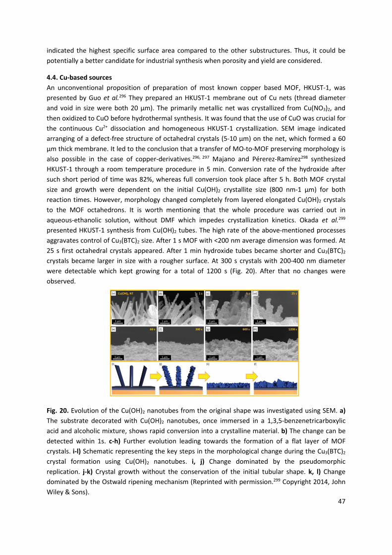
47
indicated the highest specific surface area compared to the other substructures. Thus, it could be potentially a better candidate for industrial synthesis when porosity and yield are considered.
4.4. Cu-based sources An unconventional proposition of preparation of most known copper based MOF, HKUST-1, was presented by Guo et al.296 They prepared an HKUST-1 membrane out of Cu nets (thread diameter and void in size were both 20 μm). The primarily metallic net was crystallized from Cu(NO3)2, and then oxidized to CuO before hydrothermal synthesis. It was found that the use of CuO was crucial for the continuous Cu2+ dissociation and homogeneous HKUST-1 crystallization. SEM image indicated arranging of a defect-free structure of octahedral crystals (5-10 μm) on the net, which formed a 60 μm thick membrane. It led to the conclusion that a transfer of MO-to-MOF preserving morphology is also possible in the case of copper-derivatives.296, 297 Majano and Pérerez-Ramírez298 synthesized HKUST-1 through a room temperature procedure in 5 min. Conversion rate of the hydroxide after such short period of time was 82%, whereas full conversion took place after 5 h. Both MOF crystal size and growth were dependent on the initial Cu(OH)2 crystallite size (800 nm-1 μm) for both reaction times. However, morphology changed completely from layered elongated Cu(OH)2 crystals to the MOF octahedrons. It is worth mentioning that the whole procedure was carried out in aqueous-ethanolic solution, without DMF which impedes crystallization kinetics. Okada et al.299 presented HKUST-1 synthesis from Cu(OH)2 tubes. The high rate of the above-mentioned processes aggravates control of Cu3(BTC)2 size. After 1 s MOF with <200 nm average dimension was formed. At 25 s first octahedral crystals appeared. After 1 min hydroxide tubes became shorter and Cu3(BTC)2 crystals became larger in size with a rougher surface. At 300 s crystals with 200-400 nm diameter were detectable which kept growing for a total of 1200 s (Fig. 20). After that no changes were observed.
Fig. 20. Evolution of the Cu(OH)2 nanotubes from the original shape was investigated using SEM. a) The substrate decorated with Cu(OH)2 nanotubes, once immersed in a 1,3,5-benzenetricarboxylic acid and alcoholic mixture, shows rapid conversion into a crystalline material. b) The change can be detected within 1s. c-h) Further evolution leading towards the formation of a flat layer of MOF crystals. i-l) Schematic representing the key steps in the morphological change during the Cu3(BTC)2 crystal formation using Cu(OH)2 nanotubes. i, j) Change dominated by the pseudomorphic replication. j-k) Crystal growth without the conservation of the initial tubular shape. k, l) Change dominated by the Ostwald ripening mechanism (Reprinted with permission.299 Copyright 2014, John Wiley & Sons).
48
Another preparation of well-established size of Cu3(BTC)2 was presented by Takahashi’s group. MOF crystals were prepared by conversion of Cu(OH)2 belts previously coated on a gold electrode.300 The ratio of ethanol: water has high impact on Cu3(BTC)2 crystals size due to co-solvent polarity (dielectric constant), which affects ligand deprotonation. Higher hydroxide conversion of MOF and larger octahedral crystals from several hundred to over than 3 μm were obtained in 2:5 ratio (ethanol: water). In more ethanolic mixture (5:2 ethanol: water) smaller crystals were formed. This observation implies that crystallization is dominated specifically by Ostwald ripening. More polar solvents like water (dielectric constant - 80.1) increase acidity of a mixture due to the enhanced proton release from organic linkers. Less polar ethanol (dielectric constant - 24.5) limits deprotonation, which further leads to decrease in Cu(OH)2 dissolution rate and thus shorter diameter of Cu3(BTC)2.
In 2017 Falcaro et al.301 prepared centimetre-scale, aligned two- and three-dimensional MOF films directly from a Cu(OH)2 substrate. Following a heteroepitaxial growth mechanism, the synthesis was facilitated by precise matching of the structure metrics of the organic linker and the lattice parameters of the metal hydroxide substrate. MOF crystals being oriented in one direction, the out-of-plane one, have been previously synthesized using liquid phase epitaxy, however, MOF crystals being orientated in all three directions have not been demonstrated. Orientation along all three crystallographic axes could be achieved by conversion of a crystalline metal hydroxide surface.
Zhang and Zeng302 proposed applying Cu2O as a metal source for HKUST-1 formation in a solution based synthesis with co-solvents of DMF/ethanol, which indicated nanoscale „domain growth” mechanism. After MO dissolution the starting solution became heterogeneous in metallic cations, however, the presence of oxygen in the medium allowed converting oxidation state of CuI to CuII via the following reaction: 2Cu2O + O2 + 8H+o 4Cu2+ + 4H2O. Oxidized copper ions were able to react with organic linker to form crystallites, which in time aggregated, producing larger MOF domains. Using Cu2O cubes with uniform size and shape (average edge size of 60 nm) led to the formation of 3D networks of nanocrystal MOF domains (~20 nm). It was stated that for successful MO conversion into MOF networks it is necessary to provide a specific concentration of PVP (e.g. 0.48 g/L) as a structure-directing agent. Also the polar co-solvents affected organic ligand dissociation and oxidative dissolution of ions from mineral. Under the optimized reaction temperature and time, it was possible to generate HKUST-1 with hierarchical porosity. Further investigation on the shape and size control demonstrated that ratios of metal oxide/organic linker and solvent/co-solvent are crucial for crystallization process and thus morphology of the final product. It was found that the required ratio of Cu2O/H3BTC and water/ethanol for fibers was 1:76 and 1:0.43 respectively; for rod-like crystals was 1:38 and 1:1.2 respectively. Further decrease of organic ligand amount to 1:19 ratio led to the growth of thin nanosheets with a rectangular shape.303
4.5. Other MOs as metal reservoirs Concept of MO-derived MOFs was further investigated for only several oxides such as V2O5, MgO, MnO, Bi2O3, CoO, NiO, and CdO. Vanadium PCPs, due to their porosity and electronic properties, can be applied in separation, sensing, and catalysis. First approach of vanadium based polycrystalline macrostructures [V(OH)ndc]n fabricated from V2O5 was introduced by Reboul and coworkers.304 PCPs were obtained in short 10 min microwave treatment from a water solution of V2O5 and naphthalene dicarboxylic acid (H2ndc), in the presence of ascorbic acid as a reductant. Ascorbic acid not only changed the oxidation state of vanadium from VV to VIII, but also improved the solubility of the
49
mineral.259 Combination of applied radiation and mineral precursor ended up in covering the entire surface of oxide with nuclei. V2O5-derived MOFs showed rod-like shape and had smaller and more uniform particle size than VCl3-derived ones.
Wang et al.305 presented a new synthetic strategy for Mg-MOF-74 films from MgO using solvothermal conditions. Magnesium nitrate salts were in situ produced during synthesis, notwithstanding MgO was used as a seeding agent hooked onto Al2O3 substructure. MgO released Mg2+ ions, and promoted both nucleation and growth of MOF thin films. The resulting MOF membranes demonstrated no defects in their structure, despite the presence of nitrate ions. The effect of the amount of the mineral precursor on the morphology of MOF was investigated by Maserati and his group in 2017.306 With different ratio of MgO to H4dobpdc [4,4’-dihydroxy-(1,1’-biphenyl)-3,3’-dicarboxylic acid] they presented two synthetic routes for nanocrystals (16:1) or microcrystals (2:1). In the case of not fully converted MgO to MOF, acetic acid was used as a mild etchant to separate product from MO. The final morphology of the two products was rod-like. These rods revealed an average cross-section crystallite size of ~12 nm, and a greater surface area than bulk structures. Another interesting approach used seemingly mechanochemically inert MgO in one step LAG method. Grinding MO with carboxylic acid drug derivatives, such as ibuprofen or salicylic acid in the presence of water led to complex self-assemblies process. It involved coordination to water molecules with subsequent acid-base neutralisation and molecular inclusion. In 2010 Chow et al.307 synthesized a series of diverse MOF networks via the same method by varying the amount of water coordinated to the Mg2+ centre. Similarly to previous structures bismuth subsalicylate MOF was synthesized by using ion- and liquid-assisted grinding (ILAG). The environmentally friendly method using Bi2O3 as a metal source and coordinating drugs allowed preparation of novel metallodrugs. The volume of solvent had a high impact on the final network, thus hydrated 2D crystal structure varied dependently on the water coordinates.308 To reduce the amount of water coordinates and to avoid temperature treatment it is feasible to conduct LAG procedure also in non-aqueous solution e.g. in DMF. Such example was obtained by Wang and coworkers for CdO-derived MOF.309 Milling CdO with isonicotinic acid (HINA) led to the formation of interpenetrated diamondoid network of [Cd(INA)2(OH2)]·DMF. MO-to-MOF conversion efficiency in this case is very small leaving loads of unreacted CdO.
Three-dimensional and mesoporous ZIF-67, Co-MOF-74 and Ni-MOF-74 hybrid arrays were successfully synthesized by Cai et al.,310 by using self-sacrificial CoO and NiO arrays on Ni foam with Hmim and 2,5-dihydroxyterephthalic acid as the organic linkers. Firstly MO precursor on Ni foam was prepared. Next, it was placed in the mixture of water, ethanol and DMF with 2,5-dihydroxyterephtalic acid as linker. Poor solubility of MOs at times can be still `too fast`, thus for shape-preservation procedure it needs to be lowered. In this case using only water led to too fast dissociation and nucleation in the solution, whereas for morphology control epitaxial growth is required. Hence, the addition of ethanol slowed reaction down and enabled well-defined MOF formation, meaning slow rate of dissolution was important for morphology control for this material. ZIF-67 morphology was directed by changing the pristine shape of the mineral, e.g. applying CoO wires led to rods formation, whereas CoO walls formed CoO@ZIF-67 walls. Presented growth mechanism revealed the phenomenon of shell thickening in spite of complete core surrounding. After 12 h of reaction, the size of CoO core/ZIF-67 shell changed from 100/40 nm to 53/180 nm. Continuation of the reaction led to core corrosion, but it did not stop further ZIF-shell formation. It means that organic linkers were able to deprotonate themselves and enhances CoO dissolution, on
50
top of that they could easily penetrate ZIF pores and add up to its structure. Interestingly, replacing CoO with Co3O4 did not lead to formation of ZIF-67 on the oxide Co3O4.311
The solution-mediated techniques are rather expensive and environmentally unfriendly. These problems prompted Friščić et al.311, 312 to develop an „accelerated ageing method”, which imitates geological biomineralization (mineral weathering/mineral neogenesis). MOF materials are generated from the exposure of minerals (e.g. MgO, MnO, NiO, CoO, CuO, PbO) to organic molecules (oxalate ligands) without solvent. Motillo et al.307 also introduced „accelerated aging” for ZIF-67 and ZIF-8 preparation.313, 314 This technique enabled forming ZIFs from CoO and ZnO, however it took many days (up to 11 days in some cases) to gain any hybrid structure. Additionally, beside linkers (Hmim or HEtim) salts additives are needed, such as (NH4)2SO4, KHSO4, (H2Im)2SO4·H2O, (Hcaf)(HSO4), (Hcaf)(HSO4)·H2O or (H2BIm)2(SO4), which for the morphology control purposes can be unreasonable, if once stated acidic by-products might occur or no well-defined shape and size of the final material is fabricated.
5. Controlling morphology of metal-organic frameworks-derived carbon
Since the pioneering work by Xu and coworkers315 in 2008, MOF-derived carbon (MDC) has been of particular research interest for the past decade.14, 316-321 The characteristic features of MOFs, such as high surface area, designable uniform pore size and structures, highly ordered and chemically homogeneous structures,6, 322 are partially transferred to derived carbons, so that MDCs can have tailored physicochemical properties which are difficult to be realized by other porous carbons. MOFs are now considered as “all-in-one” templates/precursors that contain both inorganic and organic constituents which can be pre-selected for preparation of targeted carbon materials.323 Inorganic metal species function as sacrificial porogens, catalysts for in situ graphitization, and active components that are useful for energy storage and heterogeneous catalysis.324-326 Organic ligands serve as mainly carbon and heteroatom sources, as well as pore forming agents. They decompose to gaseous products and/or cross-link to form porous (heteroatom-doped) amorphous carbon. In situ generated gas outflux can sometimes create additional mesopores and even macropores.327-329 The well-defined periodic arrangement of metal nodes and organic motifs in MOF often leads to a homogeneous distribution of metal or metal oxide nanoparticles in carbon matrix.320, 330 This feature even allows preparation of single atomic metal catalysts and metal-N-C active sites throughout the whole structures, which is useful for various applications.331
MOFs can be further functionalized, either by guest incorporation into the porous MOF hosts or post-synthetic modification of MOFs, to achieve improved MDC material performance.332 For instance, secondary carbon sources (furfuryl alcohol, glucose, phenolic resins) and heteroatom sources (dicyanamide for nitrogen, glyphosine and triarylphosphine for phosphorus, and dimethyl sulfoxide for sulfur) can significantly improve the textural- and electronic-properties of MDCs, respectively.319 Addition of secondary metal ions and other inorganic precursors enables preparation of diverse metallic and multi-metallic nanocatalysts.320, 330 The reaction between MOF and sulfur, selenium, or phosphorus containing chemicals at high temperature leads to formation of carbon composites with metal chalcogenides and phosphides.333, 334 Apart from MOF precursors, the final properties and structures of MDCs can also be controlled by simply varying pyrolysis conditions such as temperature, ramping rate, retention time, and gas atmosphere.335-338
Another important key advantage of MDCs is controllable particle morphologies ranging from simple 0D, 1D, 2D to complex 3D and hierarchical architectures. Carbon morphology control is
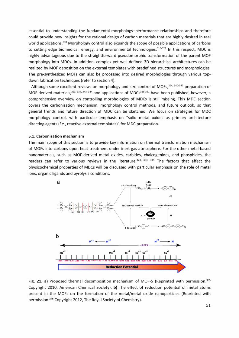
51
essential to understanding the fundamental morphology–performance relationships and therefore could provide new insights for the rational design of carbon materials that are highly desired in real world applications.339 Morphology control also expands the scope of possible applications of carbons to cutting edge biomedical, energy, and environmental technologies.316-321 In this respect, MDC is highly advantageous due to the straightforward pseudomorphic transformation of the parent MOF morphology into MDCs. In addition, complex yet well-defined 3D hierarchical architectures can be realized by MOF deposition on the external templates with predefined structures and morphologies. The pre-synthesized MOFs can also be processed into desired morphologies through various top-down fabrication techniques (refer to section 4).
Although some excellent reviews on morphology and size control of MOFs,264, 340-342 preparation of MOF-derived materials,253, 334, 343, 344 and applications of MDCs316-321 have been published, however, a comprehensive overview on controlling morphologies of MDCs is still missing. This MDC section covers the carbonization mechanism, morphology control methods, and future outlook, so that general trends and future direction of MDC can be sketched. We focus on strategies for MDC morphology control, with particular emphasis on “solid metal oxides as primary architecture directing agents (i.e., reactive external templates)” for MDC preparation.
5.1. Carbonization mechanism The main scope of this section is to provide key information on thermal transformation mechanism of MOFs into carbons upon heat treatment under inert gas atmosphere. For the other metal-based nanomaterials, such as MOF-derived metal oxides, carbides, chalcogenides, and phosphides, the readers can refer to various reviews in the literature.323, 334, 345 The factors that affect the physicochemical properties of MDCs will be discussed with particular emphasis on the role of metal ions, organic ligands and pyrolysis conditions.
Fig. 21. a) Proposed thermal decomposition mechanism of MOF-5 (Reprinted with permission.335 Copyright 2010, American Chemical Society). b) The effect of reduction potential of metal atoms present in the MOFs on the formation of the metal/metal oxide nanoparticles (Reprinted with permission.346 Copyright 2012, The Royal Society of Chemistry).
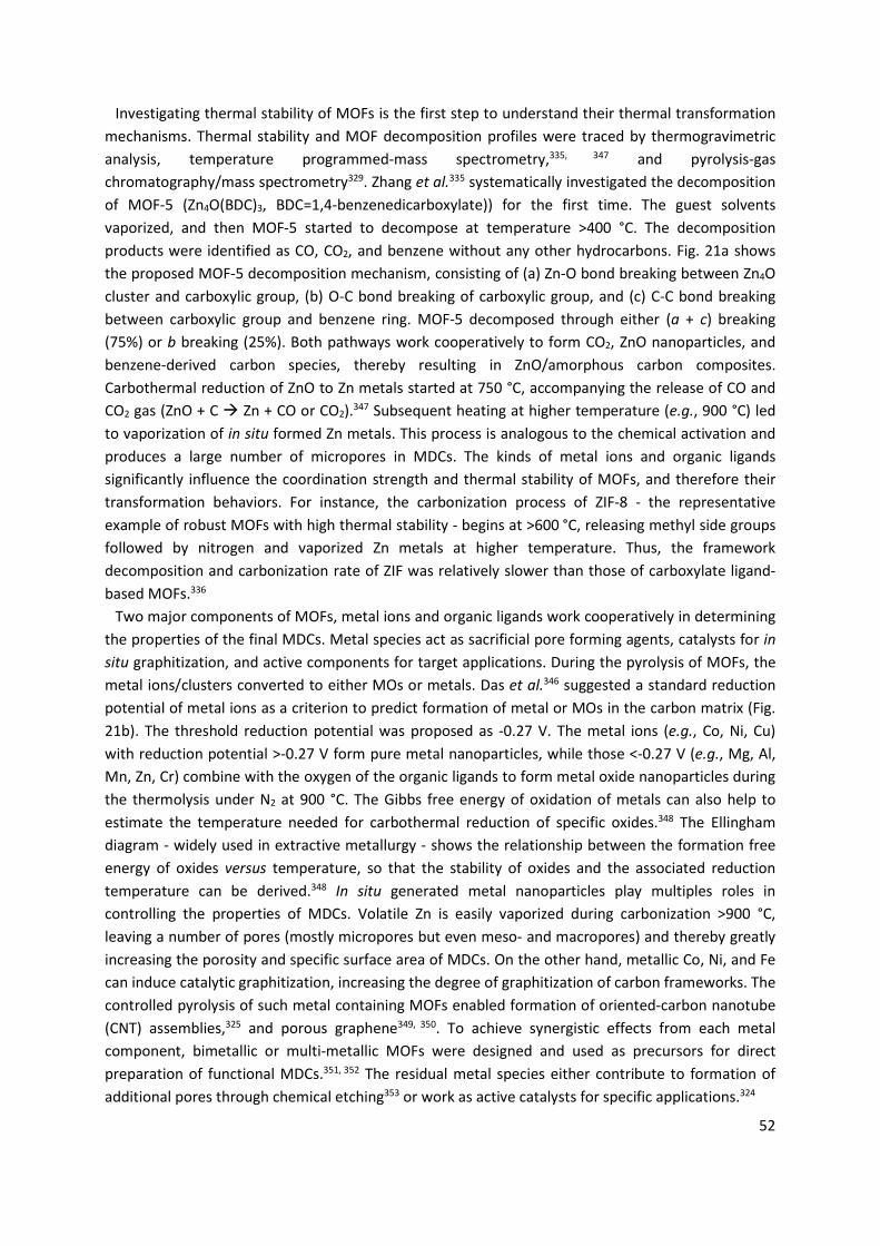
52
Investigating thermal stability of MOFs is the first step to understand their thermal transformation mechanisms. Thermal stability and MOF decomposition profiles were traced by thermogravimetric analysis, temperature programmed-mass spectrometry,335, 347 and pyrolysis-gas chromatography/mass spectrometry329. Zhang et al.335 systematically investigated the decomposition of MOF-5 (Zn4O(BDC)3, BDC=1,4-benzenedicarboxylate)) for the first time. The guest solvents vaporized, and then MOF-5 started to decompose at temperature >400 °C. The decomposition products were identified as CO, CO2, and benzene without any other hydrocarbons. Fig. 21a shows the proposed MOF-5 decomposition mechanism, consisting of (a) Zn-O bond breaking between Zn4O cluster and carboxylic group, (b) O-C bond breaking of carboxylic group, and (c) C-C bond breaking between carboxylic group and benzene ring. MOF-5 decomposed through either (a + c) breaking (75%) or b breaking (25%). Both pathways work cooperatively to form CO2, ZnO nanoparticles, and benzene-derived carbon species, thereby resulting in ZnO/amorphous carbon composites. Carbothermal reduction of ZnO to Zn metals started at 750 °C, accompanying the release of CO and CO2 gas (ZnO + C Æ Zn + CO or CO2).347 Subsequent heating at higher temperature (e.g., 900 °C) led to vaporization of in situ formed Zn metals. This process is analogous to the chemical activation and produces a large number of micropores in MDCs. The kinds of metal ions and organic ligands significantly influence the coordination strength and thermal stability of MOFs, and therefore their transformation behaviors. For instance, the carbonization process of ZIF-8 - the representative example of robust MOFs with high thermal stability - begins at >600 °C, releasing methyl side groups followed by nitrogen and vaporized Zn metals at higher temperature. Thus, the framework decomposition and carbonization rate of ZIF was relatively slower than those of carboxylate ligand-based MOFs.336
Two major components of MOFs, metal ions and organic ligands work cooperatively in determining the properties of the final MDCs. Metal species act as sacrificial pore forming agents, catalysts for in situ graphitization, and active components for target applications. During the pyrolysis of MOFs, the metal ions/clusters converted to either MOs or metals. Das et al.346 suggested a standard reduction potential of metal ions as a criterion to predict formation of metal or MOs in the carbon matrix (Fig. 21b). The threshold reduction potential was proposed as -0.27 V. The metal ions (e.g., Co, Ni, Cu) with reduction potential >-0.27 V form pure metal nanoparticles, while those <-0.27 V (e.g., Mg, Al, Mn, Zn, Cr) combine with the oxygen of the organic ligands to form metal oxide nanoparticles during the thermolysis under N2 at 900 °C. The Gibbs free energy of oxidation of metals can also help to estimate the temperature needed for carbothermal reduction of specific oxides.348 The Ellingham diagram - widely used in extractive metallurgy - shows the relationship between the formation free energy of oxides versus temperature, so that the stability of oxides and the associated reduction temperature can be derived.348 In situ generated metal nanoparticles play multiples roles in controlling the properties of MDCs. Volatile Zn is easily vaporized during carbonization >900 °C, leaving a number of pores (mostly micropores but even meso- and macropores) and thereby greatly increasing the porosity and specific surface area of MDCs. On the other hand, metallic Co, Ni, and Fe can induce catalytic graphitization, increasing the degree of graphitization of carbon frameworks. The controlled pyrolysis of such metal containing MOFs enabled formation of oriented-carbon nanotube (CNT) assemblies,325 and porous graphene349, 350. To achieve synergistic effects from each metal component, bimetallic or multi-metallic MOFs were designed and used as precursors for direct preparation of functional MDCs.351, 352 The residual metal species either contribute to formation of additional pores through chemical etching353 or work as active catalysts for specific applications.324
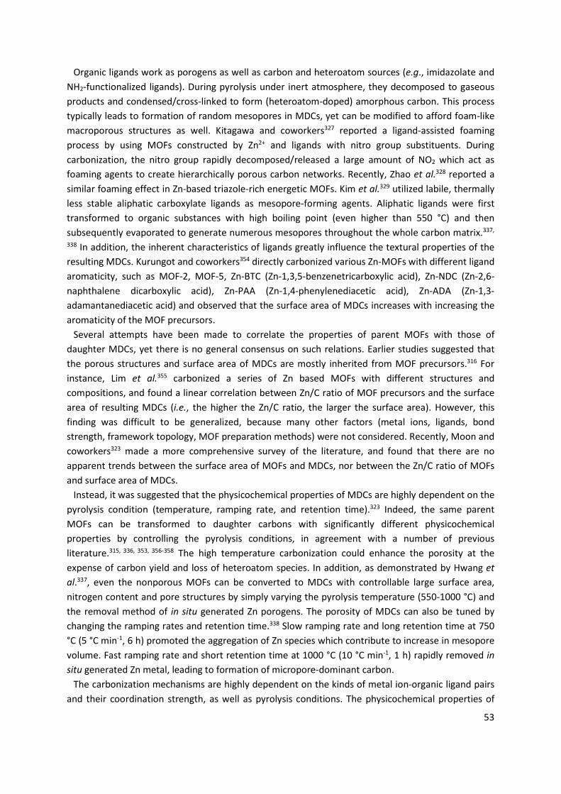
53
Organic ligands work as porogens as well as carbon and heteroatom sources (e.g., imidazolate and NH2-functionalized ligands). During pyrolysis under inert atmosphere, they decomposed to gaseous products and condensed/cross-linked to form (heteroatom-doped) amorphous carbon. This process typically leads to formation of random mesopores in MDCs, yet can be modified to afford foam-like macroporous structures as well. Kitagawa and coworkers327 reported a ligand-assisted foaming process by using MOFs constructed by Zn2+ and ligands with nitro group substituents. During carbonization, the nitro group rapidly decomposed/released a large amount of NO2 which act as foaming agents to create hierarchically porous carbon networks. Recently, Zhao et al.328 reported a similar foaming effect in Zn-based triazole-rich energetic MOFs. Kim et al.329 utilized labile, thermally less stable aliphatic carboxylate ligands as mesopore-forming agents. Aliphatic ligands were first transformed to organic substances with high boiling point (even higher than 550 °C) and then subsequently evaporated to generate numerous mesopores throughout the whole carbon matrix.337,
338 In addition, the inherent characteristics of ligands greatly influence the textural properties of the resulting MDCs. Kurungot and coworkers354 directly carbonized various Zn-MOFs with different ligand aromaticity, such as MOF-2, MOF-5, Zn-BTC (Zn-1,3,5-benzenetricarboxylic acid), Zn-NDC (Zn-2,6-naphthalene dicarboxylic acid), Zn-PAA (Zn-1,4-phenylenediacetic acid), Zn-ADA (Zn-1,3-adamantanediacetic acid) and observed that the surface area of MDCs increases with increasing the aromaticity of the MOF precursors.
Several attempts have been made to correlate the properties of parent MOFs with those of daughter MDCs, yet there is no general consensus on such relations. Earlier studies suggested that the porous structures and surface area of MDCs are mostly inherited from MOF precursors.316 For instance, Lim et al.355 carbonized a series of Zn based MOFs with different structures and compositions, and found a linear correlation between Zn/C ratio of MOF precursors and the surface area of resulting MDCs (i.e., the higher the Zn/C ratio, the larger the surface area). However, this finding was difficult to be generalized, because many other factors (metal ions, ligands, bond strength, framework topology, MOF preparation methods) were not considered. Recently, Moon and coworkers323 made a more comprehensive survey of the literature, and found that there are no apparent trends between the surface area of MOFs and MDCs, nor between the Zn/C ratio of MOFs and surface area of MDCs.
Instead, it was suggested that the physicochemical properties of MDCs are highly dependent on the pyrolysis condition (temperature, ramping rate, and retention time).323 Indeed, the same parent MOFs can be transformed to daughter carbons with significantly different physicochemical properties by controlling the pyrolysis conditions, in agreement with a number of previous literature.315, 336, 353, 356-358 The high temperature carbonization could enhance the porosity at the expense of carbon yield and loss of heteroatom species. In addition, as demonstrated by Hwang et al.337, even the nonporous MOFs can be converted to MDCs with controllable large surface area, nitrogen content and pore structures by simply varying the pyrolysis temperature (550-1000 °C) and the removal method of in situ generated Zn porogens. The porosity of MDCs can also be tuned by changing the ramping rates and retention time.338 Slow ramping rate and long retention time at 750 °C (5 °C min-1, 6 h) promoted the aggregation of Zn species which contribute to increase in mesopore volume. Fast ramping rate and short retention time at 1000 °C (10 °C min-1, 1 h) rapidly removed in situ generated Zn metal, leading to formation of micropore-dominant carbon.
The carbonization mechanisms are highly dependent on the kinds of metal ion-organic ligand pairs and their coordination strength, as well as pyrolysis conditions. The physicochemical properties of
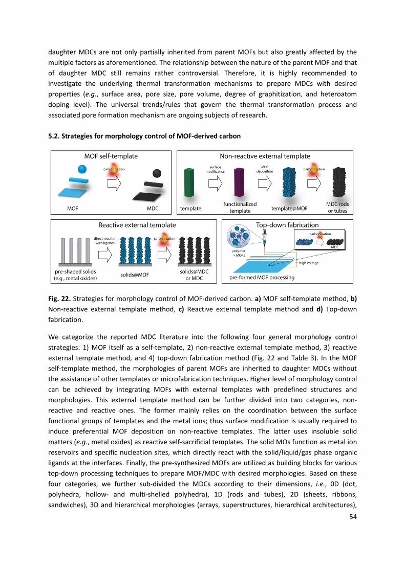
54
daughter MDCs are not only partially inherited from parent MOFs but also greatly affected by the multiple factors as aforementioned. The relationship between the nature of the parent MOF and that of daughter MDC still remains rather controversial. Therefore, it is highly recommended to investigate the underlying thermal transformation mechanisms to prepare MDCs with desired properties (e.g., surface area, pore size, pore volume, degree of graphitization, and heteroatom doping level). The universal trends/rules that govern the thermal transformation process and associated pore formation mechanism are ongoing subjects of research. 5.2. Strategies for morphology control of MOF-derived carbon
Fig. 22. Strategies for morphology control of MOF-derived carbon. a) MOF self-template method, b) Non-reactive external template method, c) Reactive external template method and d) Top-down fabrication.
We categorize the reported MDC literature into the following four general morphology control strategies: 1) MOF itself as a self-template, 2) non-reactive external template method, 3) reactive external template method, and 4) top-down fabrication method (Fig. 22 and Table 3). In the MOF self-template method, the morphologies of parent MOFs are inherited to daughter MDCs without the assistance of other templates or microfabrication techniques. Higher level of morphology control can be achieved by integrating MOFs with external templates with predefined structures and morphologies. This external template method can be further divided into two categories, non-reactive and reactive ones. The former mainly relies on the coordination between the surface functional groups of templates and the metal ions; thus surface modification is usually required to induce preferential MOF deposition on non-reactive templates. The latter uses insoluble solid matters (e.g., metal oxides) as reactive self-sacrificial templates. The solid MOs function as metal ion reservoirs and specific nucleation sites, which directly react with the solid/liquid/gas phase organic ligands at the interfaces. Finally, the pre-synthesized MOFs are utilized as building blocks for various top-down processing techniques to prepare MOF/MDC with desired morphologies. Based on these four categories, we further sub-divided the MDCs according to their dimensions, i.e., 0D (dot, polyhedra, hollow- and multi-shelled polyhedra), 1D (rods and tubes), 2D (sheets, ribbons, sandwiches), 3D and hierarchical morphologies (arrays, superstructures, hierarchical architectures),

55
and discuss their formation mechanism as well as their thermal transformation process. We place particular emphasis on ‘solid MOs as reactive external templates’, and comprehensively review the available literature on this strategy as a versatile tool to obtain complex yet sophisticated carbon architectures with multiple levels of hierarchies (see also section 4).
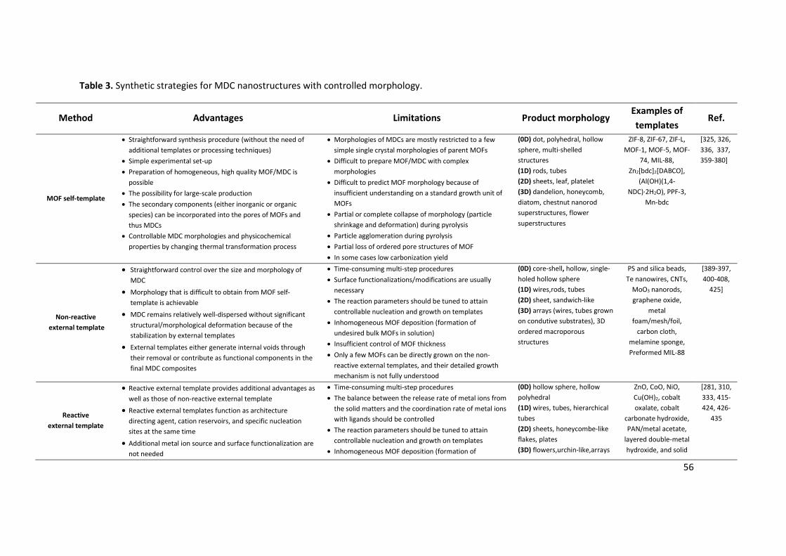
56
Table 3. Synthetic strategies for MDC nanostructures with controlled morphology.
Method Advantages Limitations Product morphology Examples of templates
Ref.
MOF self-template
x Straightforward synthesis procedure (without the need of additional templates or processing techniques)
x Simple experimental set-up x Preparation of homogeneous, high quality MOF/MDC is
possible x The possibility for large-scale production x The secondary components (either inorganic or organic
species) can be incorporated into the pores of MOFs and thus MDCs
x Controllable MDC morphologies and physicochemical properties by changing thermal transformation process
x Morphologies of MDCs are mostly restricted to a few simple single crystal morphologies of parent MOFs
x Difficult to prepare MOF/MDC with complex morphologies
x Difficult to predict MOF morphology because of insufficient understanding on a standard growth unit of MOFs
x Partial or complete collapse of morphology (particle shrinkage and deformation) during pyrolysis
x Particle agglomeration during pyrolysis x Partial loss of ordered pore structures of MOF x In some cases low carbonization yield
(0D) dot, polyhedral, hollow sphere, multi-shelled structures (1D) rods, tubes (2D) sheets, leaf, platelet (3D) dandelion, honeycomb, diatom, chestnut nanorod superstructures, flower superstructures
ZIF-8, ZIF-67, ZIF-L, MOF-1, MOF-5, MOF-
74, MIL-88, Zn2[bdc]2[DABCO],
(Al(OH)(1,4-NDC)·2H2O), PPF-3,
Mn-bdc
[325, 326, 336, 337, 359-380]
Non-reactive external template
x Straightforward control over the size and morphology of MDC
x Morphology that is difficult to obtain from MOF self-template is achievable
x MDC remains relatively well-dispersed without significant structural/morphological deformation because of the stabilization by external templates
x External templates either generate internal voids through their removal or contribute as functional components in the final MDC composites
x Time-consuming multi-step procedures x Surface functionalizations/modifications are usually
necessary x The reaction parameters should be tuned to attain
controllable nucleation and growth on templates x Inhomogeneous MOF deposition (formation of
undesired bulk MOFs in solution) x Insufficient control of MOF thickness x Only a few MOFs can be directly grown on the non-
reactive external templates, and their detailed growth mechanism is not fully understood
(0D) core-shell, hollow, single-holed hollow sphere (1D) wires,rods, tubes (2D) sheet, sandwich-like (3D) arrays (wires, tubes grown on condutive substrates), 3D ordered macroporous structures
PS and silica beads, Te nanowires, CNTs,
MoO3 nanorods, graphene oxide,
metal foam/mesh/foil,
carbon cloth, melamine sponge, Preformed MIL-88
[389-397, 400-408,
425]
Reactive external template
x Reactive external template provides additional advantages as well as those of non-reactive external template
x Reactive external templates function as architecture directing agent, cation reservoirs, and specific nucleation sites at the same time
x Additional metal ion source and surface functionalization are not needed
x Time-consuming multi-step procedures x The balance between the release rate of metal ions from
the solid matters and the coordination rate of metal ions with ligands should be controlled
x The reaction parameters should be tuned to attain controllable nucleation and growth on templates
x Inhomogeneous MOF deposition (formation of
(0D) hollow sphere, hollow polyhedral (1D) wires, tubes, hierarchical tubes (2D) sheets, honeycombe-like flakes, plates (3D) flowers,urchin-like,arrays
ZnO, CoO, NiO, Cu(OH)2, cobalt oxalate, cobalt
carbonate hydroxide, PAN/metal acetate,
layered double-metal hydroxide, and solid
[281, 310, 333, 415-424, 426-
435
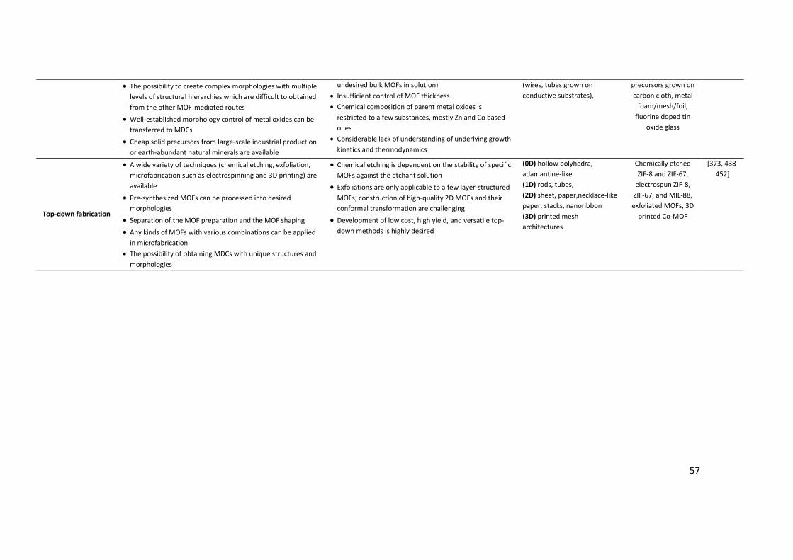
57
x The possibility to create complex morphologies with multiple levels of structural hierarchies which are difficult to obtained from the other MOF-mediated routes
x Well-established morphology control of metal oxides can be transferred to MDCs
x Cheap solid precursors from large-scale industrial production or earth-abundant natural minerals are available
undesired bulk MOFs in solution) x Insufficient control of MOF thickness x Chemical composition of parent metal oxides is
restricted to a few substances, mostly Zn and Co based ones
x Considerable lack of understanding of underlying growth kinetics and thermodynamics
(wires, tubes grown on conductive substrates),
precursors grown on carbon cloth, metal
foam/mesh/foil, fluorine doped tin
oxide glass
Top-down fabrication
x A wide variety of techniques (chemical etching, exfoliation, microfabrication such as electrospinning and 3D printing) are available
x Pre-synthesized MOFs can be processed into desired morphologies
x Separation of the MOF preparation and the MOF shaping x Any kinds of MOFs with various combinations can be applied
in microfabrication x The possibility of obtaining MDCs with unique structures and
morphologies
x Chemical etching is dependent on the stability of specific MOFs against the etchant solution
x Exfoliations are only applicable to a few layer-structured MOFs; construction of high-quality 2D MOFs and their conformal transformation are challenging
x Development of low cost, high yield, and versatile top-down methods is highly desired
(0D) hollow polyhedra, adamantine-like (1D) rods, tubes, (2D) sheet, paper,necklace-like paper, stacks, nanoribbon (3D) printed mesh architectures
Chemically etched ZIF-8 and ZIF-67,
electrospun ZIF-8, ZIF-67, and MIL-88, exfoliated MOFs, 3D
printed Co-MOF
[373, 438-452]
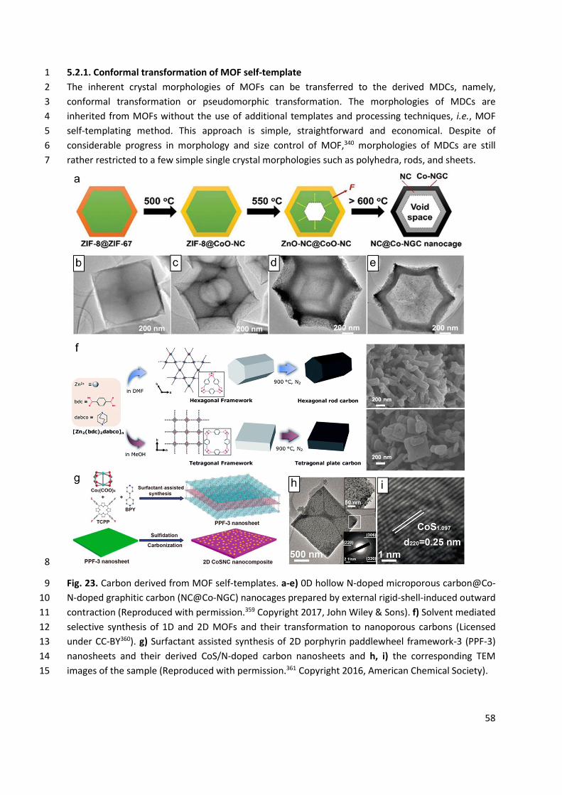
58
5.2.1. Conformal transformation of MOF self-template 1 The inherent crystal morphologies of MOFs can be transferred to the derived MDCs, namely, 2 conformal transformation or pseudomorphic transformation. The morphologies of MDCs are 3 inherited from MOFs without the use of additional templates and processing techniques, i.e., MOF 4 self-templating method. This approach is simple, straightforward and economical. Despite of 5 considerable progress in morphology and size control of MOF,340 morphologies of MDCs are still 6 rather restricted to a few simple single crystal morphologies such as polyhedra, rods, and sheets. 7
8
Fig. 23. Carbon derived from MOF self-templates. a-e) 0D hollow N-doped microporous carbon@Co-9 N-doped graphitic carbon (NC@Co-NGC) nanocages prepared by external rigid-shell-induced outward 10 contraction (Reproduced with permission.359 Copyright 2017, John Wiley & Sons). f) Solvent mediated 11 selective synthesis of 1D and 2D MOFs and their transformation to nanoporous carbons (Licensed 12 under CC-BY360). g) Surfactant assisted synthesis of 2D porphyrin paddlewheel framework-3 (PPF-3) 13 nanosheets and their derived CoS/N-doped carbon nanosheets and h, i) the corresponding TEM 14 images of the sample (Reproduced with permission.361 Copyright 2016, American Chemical Society). 15
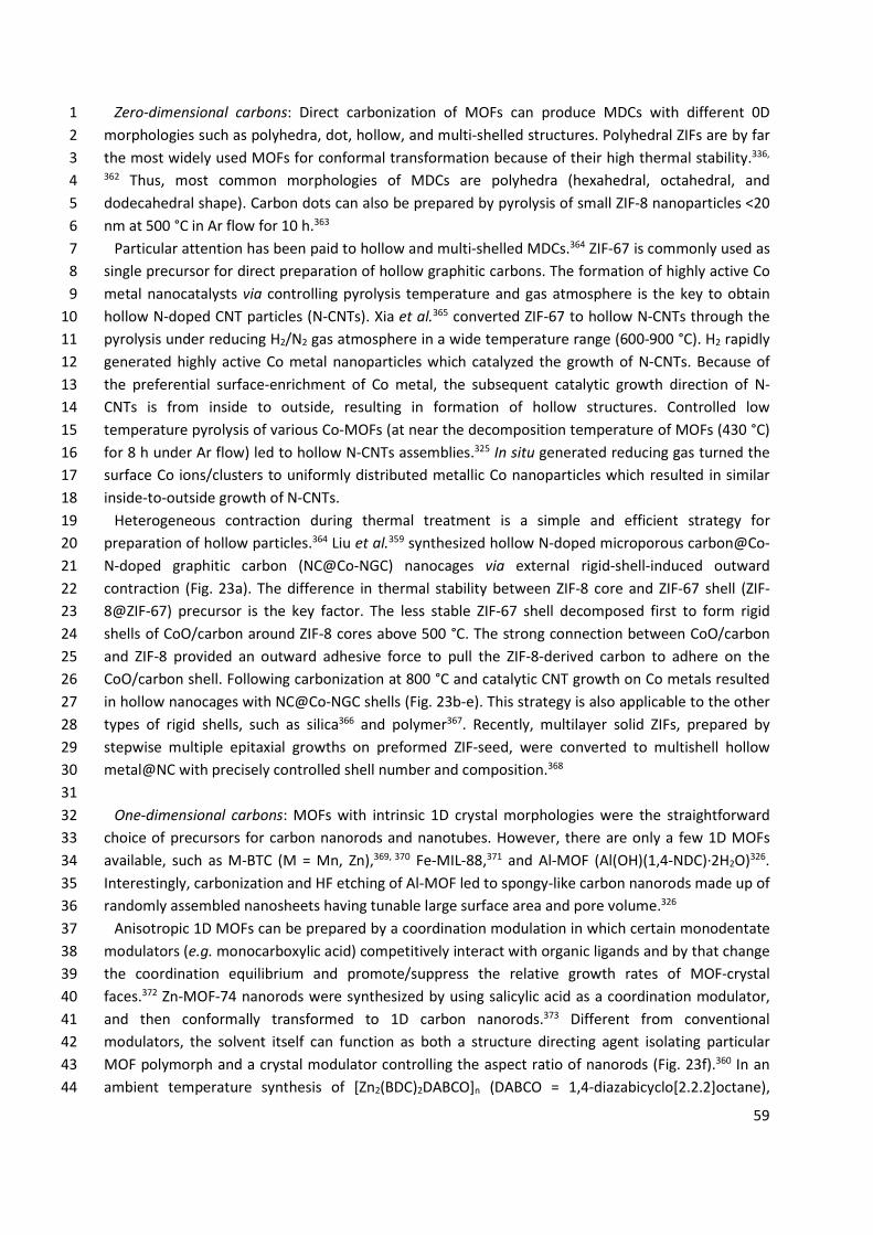
59
Zero-dimensional carbons: Direct carbonization of MOFs can produce MDCs with different 0D 1 morphologies such as polyhedra, dot, hollow, and multi-shelled structures. Polyhedral ZIFs are by far 2 the most widely used MOFs for conformal transformation because of their high thermal stability.336, 3 362 Thus, most common morphologies of MDCs are polyhedra (hexahedral, octahedral, and 4 dodecahedral shape). Carbon dots can also be prepared by pyrolysis of small ZIF-8 nanoparticles <20 5 nm at 500 °C in Ar flow for 10 h.363 6
Particular attention has been paid to hollow and multi-shelled MDCs.364 ZIF-67 is commonly used as 7 single precursor for direct preparation of hollow graphitic carbons. The formation of highly active Co 8 metal nanocatalysts via controlling pyrolysis temperature and gas atmosphere is the key to obtain 9 hollow N-doped CNT particles (N-CNTs). Xia et al.365 converted ZIF-67 to hollow N-CNTs through the 10 pyrolysis under reducing H2/N2 gas atmosphere in a wide temperature range (600-900 °C). H2 rapidly 11 generated highly active Co metal nanoparticles which catalyzed the growth of N-CNTs. Because of 12 the preferential surface-enrichment of Co metal, the subsequent catalytic growth direction of N-13 CNTs is from inside to outside, resulting in formation of hollow structures. Controlled low 14 temperature pyrolysis of various Co-MOFs (at near the decomposition temperature of MOFs (430 °C) 15 for 8 h under Ar flow) led to hollow N-CNTs assemblies.325 In situ generated reducing gas turned the 16 surface Co ions/clusters to uniformly distributed metallic Co nanoparticles which resulted in similar 17 inside-to-outside growth of N-CNTs. 18
Heterogeneous contraction during thermal treatment is a simple and efficient strategy for 19 preparation of hollow particles.364 Liu et al.359 synthesized hollow N-doped microporous carbon@Co-20 N-doped graphitic carbon (NC@Co-NGC) nanocages via external rigid-shell-induced outward 21 contraction (Fig. 23a). The difference in thermal stability between ZIF-8 core and ZIF-67 shell (ZIF-22 8@ZIF-67) precursor is the key factor. The less stable ZIF-67 shell decomposed first to form rigid 23 shells of CoO/carbon around ZIF-8 cores above 500 °C. The strong connection between CoO/carbon 24 and ZIF-8 provided an outward adhesive force to pull the ZIF-8-derived carbon to adhere on the 25 CoO/carbon shell. Following carbonization at 800 °C and catalytic CNT growth on Co metals resulted 26 in hollow nanocages with NC@Co-NGC shells (Fig. 23b-e). This strategy is also applicable to the other 27 types of rigid shells, such as silica366 and polymer367. Recently, multilayer solid ZIFs, prepared by 28 stepwise multiple epitaxial growths on preformed ZIF-seed, were converted to multishell hollow 29 metal@NC with precisely controlled shell number and composition.368 30
31 One-dimensional carbons: MOFs with intrinsic 1D crystal morphologies were the straightforward 32
choice of precursors for carbon nanorods and nanotubes. However, there are only a few 1D MOFs 33 available, such as M-BTC (M = Mn, Zn),369, 370 Fe-MIL-88,371 and Al-MOF (Al(OH)(1,4-NDC)·2H2O)326. 34 Interestingly, carbonization and HF etching of Al-MOF led to spongy-like carbon nanorods made up of 35 randomly assembled nanosheets having tunable large surface area and pore volume.326 36
Anisotropic 1D MOFs can be prepared by a coordination modulation in which certain monodentate 37 modulators (e.g. monocarboxylic acid) competitively interact with organic ligands and by that change 38 the coordination equilibrium and promote/suppress the relative growth rates of MOF-crystal 39 faces.372 Zn-MOF-74 nanorods were synthesized by using salicylic acid as a coordination modulator, 40 and then conformally transformed to 1D carbon nanorods.373 Different from conventional 41 modulators, the solvent itself can function as both a structure directing agent isolating particular 42 MOF polymorph and a crystal modulator controlling the aspect ratio of nanorods (Fig. 23f).360 In an 43 ambient temperature synthesis of [Zn2(BDC)2DABCO]n (DABCO = 1,4-diazabicyclo[2.2.2]octane), 44
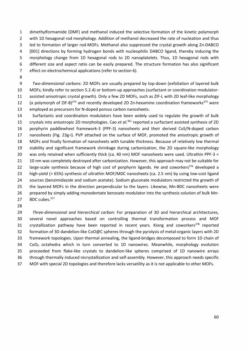
60
dimethylformamide (DMF) and methanol induced the selective formation of the kinetic polymorph 1 with 1D hexagonal rod morphology. Addition of methanol decreased the rate of nucleation and thus 2 led to formation of larger rod-MOFs. Methanol also suppressed the crystal growth along Zn-DABCO 3 [001] directions by forming hydrogen bonds with nucleophilic DABCO ligand, thereby inducing the 4 morphology change from 1D hexagonal rods to 2D nanoplatelets. Thus, 1D hexagonal rods with 5 different size and aspect ratio can be easily prepared. The structure formation has also significant 6 effect on electrochemical applications (refer to section 6). 7
8 Two-dimensional carbons: 2D MOFs are usually prepared by top-down (exfoliation of layered bulk 9
MOFs; kindly refer to section 5.2.4) or bottom-up approaches (surfactant or coordination modulator-10 assisted anisotropic crystal growth). Only a few 2D MOFs, such as ZIF-L with 2D leaf-like morphology 11 (a polymorph of ZIF-8)374 and recently developed 2D Zn-hexamine coordination frameworks375 were 12 employed as precursors for N-doped porous carbon nanosheets. 13
Surfactants and coordination modulators have been widely used to regulate the growth of bulk 14 crystals into anisotropic 2D morphologies. Cao et al.361 reported a surfactant assisted synthesis of 2D 15 porphyrin paddlewheel framework-3 (PPF-3) nanosheets and their derived CoS/N-doped carbon 16 nanosheets (Fig. 23g-i). PVP attached on the surface of MOF, promoted the anisotropic growth of 17 MOFs and finally formation of nanosheets with tunable thickness. Because of relatively low thermal 18 stability and significant framework shrinkage during carbonization, the 2D square-like morphology 19 was only retained when sufficiently thick (ca. 40 nm) MOF nanosheets were used. Ultrathin PPF-3 < 20 10 nm was completely destroyed after carbonization. However, this approach may not be suitable for 21 large-scale synthesis because of high cost of porphyrin ligands. He and coworkers376 developed a 22 high-yield (> 65%) synthesis of ultrathin MOF/MDC nanosheets (ca. 2.5 nm) by using low-cost ligand 23 sources (benzimidazole and sodium acetate). Sodium gluconate modulators restricted the growth of 24 the layered MOFs in the direction perpendicular to the layers. Likewise, Mn-BDC nanosheets were 25 prepared by simply adding monodentate benzoate modulator into the synthesis solution of bulk Mn-26 BDC cubes.377 27
28 Three-dimensional and hierarchical carbon: For preparation of 3D and hierarchical architectures, 29
several novel approaches based on controlling thermal transformation process and MOF 30 crystallization pathway have been reported in recent years. Xiong and coworkers378 reported 31 formation of 3D dandelion-like CoO@C spheres through the pyrolysis of metal-organic layers with 2D 32 framework topologies. Upon thermal annealing, the ligand-bridges decomposed to form 1D chain of 33 CoO6 octahedra which in turn converted to 1D nanowires. Meanwhile, morphology evolution 34 proceeded from flake-like crystals to dandelion-like spheres comprised of 1D nanowire arrays 35 through thermally induced recrystallization and self-assembly. However, this approach needs specific 36 MOF with special 2D topologies and therefore lacks versatility as it is not applicable to other MOFs. 37
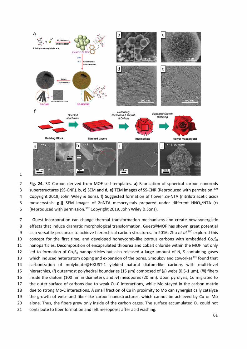
61
1
Fig. 24. 3D Carbon derived from MOF self-templates. a) Fabrication of spherical carbon nanorods 2 superstructures (SS-CNR). b, c) SEM and d, e) TEM images of SS-CNR (Reproduced with permission.379 3 Copyright 2019, John Wiley & Sons). f) Suggested formation of flower Zn-NTA (nitrilotriacetic acid) 4 mesocrystals. g-j) SEM images of ZnNTA mesocrystals prepared under different HNO3/NTA (r) 5 (Reproduced with permission.337 Copyright 2019, John Wiley & Sons). 6
Guest incorporation can change thermal transformation mechanisms and create new synergistic 7 effects that induce dramatic morphological transformation. Guest@MOF has shown great potential 8 as a versatile precursor to achieve hierarchical carbon structures. In 2016, Zhu et al.380 explored this 9 concept for the first time, and developed honeycomb-like porous carbons with embedded Co9S8 10 nanoparticles. Decomposition of encapsulated thiourea and cobalt chloride within the MOF not only 11 led to formation of Co9S8 nanoparticles but also released a large amount of N, S-containing gases 12 which induced heteroatom doping and expansion of the pores. Smoukov and coworkes381 found that 13 carbonization of molybdate@HKUST-1 yielded natural diatom-like carbons with multi-level 14 hierarchies, (i) outermost polyhedral boundaries (15 μm) composed of (ii) webs (0.5-1 μm), (iii) fibers 15 inside the diatom (100 nm in diameter), and iv) mesopores (20 nm). Upon pyrolysis, Cu migrated to 16 the outer surface of carbons due to weak Cu-C interactions, while Mo stayed in the carbon matrix 17 due to strong Mo-C interactions. A small fraction of Cu in proximity to Mo can synergistically catalyze 18 the growth of web- and fiber-like carbon nanostructures, which cannot be achieved by Cu or Mo 19 alone. Thus, the fibers grew only inside of the carbon cages. The surface accumulated Cu could not 20 contribute to fiber formation and left mesopores after acid washing. 21
62
Of particular interest in this research area is the development of hierarchical carbons with well-1 defined 3D superstructures, which can show novel collective properties that are considerably better 2 than the sum of their parts. However, the examples as such are still very rare. Xu and coworkers379 3 fabricated a spherical superstructure of carbon nanorods with hierarchical pores (Fig. 24a). In a 4 hydrothermal reaction condition, the presynthesized spherical Zn-MOF-74 (Zn2(C8H4O6)) 5 nanoparticles were firstly transformed into Zn(H2O)2(C8H4O6) nanorods having different crystal 6 structures, and then self-organized to chestnut-like-superstructures. The use of Zn-MOF-74 (a 7 precursor), water (a solvent), urea (a crystal modulator) was critical for controlled dissolution and 8 recrystallization to obtain the final 3D superstructures with radially oriented 1D nanorods (Fig. 24b-9 e). Very recently, Hwang et al.337 reported hierarchically porous 3D flower-like carbon 10 superstructures through direct thermal transformation of bio-inspired MOF mesocrystals (Fig. 24f). 11 The initially formed 2D nanosheet acted as a primary building block that underwent oriented 12 attachment and mesoscale assembly. The secondary nucleation and growth on the preformed layers 13 resulted in formation of 3D flower-like mesocrystals composed of 2D nanosheets. Nitric acid-14 mediated kinetics control enabled the morphogenesis from 2D nanosheets to 3D flower-like 15 superstructures with controllable particle size and dimensions (Fig. 24g-j). Finally, the mesocrystals 16 were converted into porous carbon materials. 17
Challenges and opportunities: The use of MOFs as sole precursor for MDCs still suffers from the 18 following problems. High temperature thermal transformation often leads to a partial or complete 19 collapse of the original MOF morphology, and is sometimes accompanied by particle agglomerations 20 and loss of ordered pore structure. These drawbacks could be partially overcome by stabilizing MOFs 21 with the well-defined external templates, which will be discussed in the following sections. In this 22 regard, development of thermally stable MOFs with various compositions and structures (other than 23 ZIFs) is highly desired. Furthermore, direct fabrication of MOF with multiple levels of structural 24 hierarchy still remains a great challenge because of single crystalline nature of MOFs and incomplete 25 understanding of their crystallization mechanism. In a classical crystallization theory, the crystal 26 morphologies likely reflect the replication/amplification of the unit cells. Although the SBU concept 27 has been well established to predict/determine the framework topologies, however, SBUs cannot be 28 simply considered as growth units because they are oriented in the network in a complicated way.382 29 Therefore, further understandings on a standard growth unit of MOFs and associated crystallization 30 mechanism are highly required. 31
To circumvent this issue, a nonclassical crystallization pathway for morphology control of MOFs has 32 been recently proposed.337, 383 Natural mineralization often follows this pathway to create 33 sophisticated 3D mesocrystals via particle-mediated growth and attachment, as observed in various 34 biominerals (e.g., bone, nacre, sea urchins).384, 385 Mesocrystal is a kind of superstructure consisting 35 of individual nanoparticles in crystallographic register with defined order.384, 385 Inspired by nature, 36 Schmidt and coworkers383 reported double hydrophilic block copolymer-mediated morphogenesis of 37 MOF mesocrystals with high level of structure control, such as kinetic formation of MOF mesocrystals 38 and their recrystallization to MOF mesocrystals with thermodynamic structure, as well as 39 hybridization of two distinct MOFs. This approach opens a new avenue for morphogenesis of MOFs 40 and thus possibly MDCs. Along this line, we also believe that in situ hybridization of MOF and other 41 components into single architectures (e.g., MOF-MOF, MOF-polymers)352, 386-388 is a promising 42
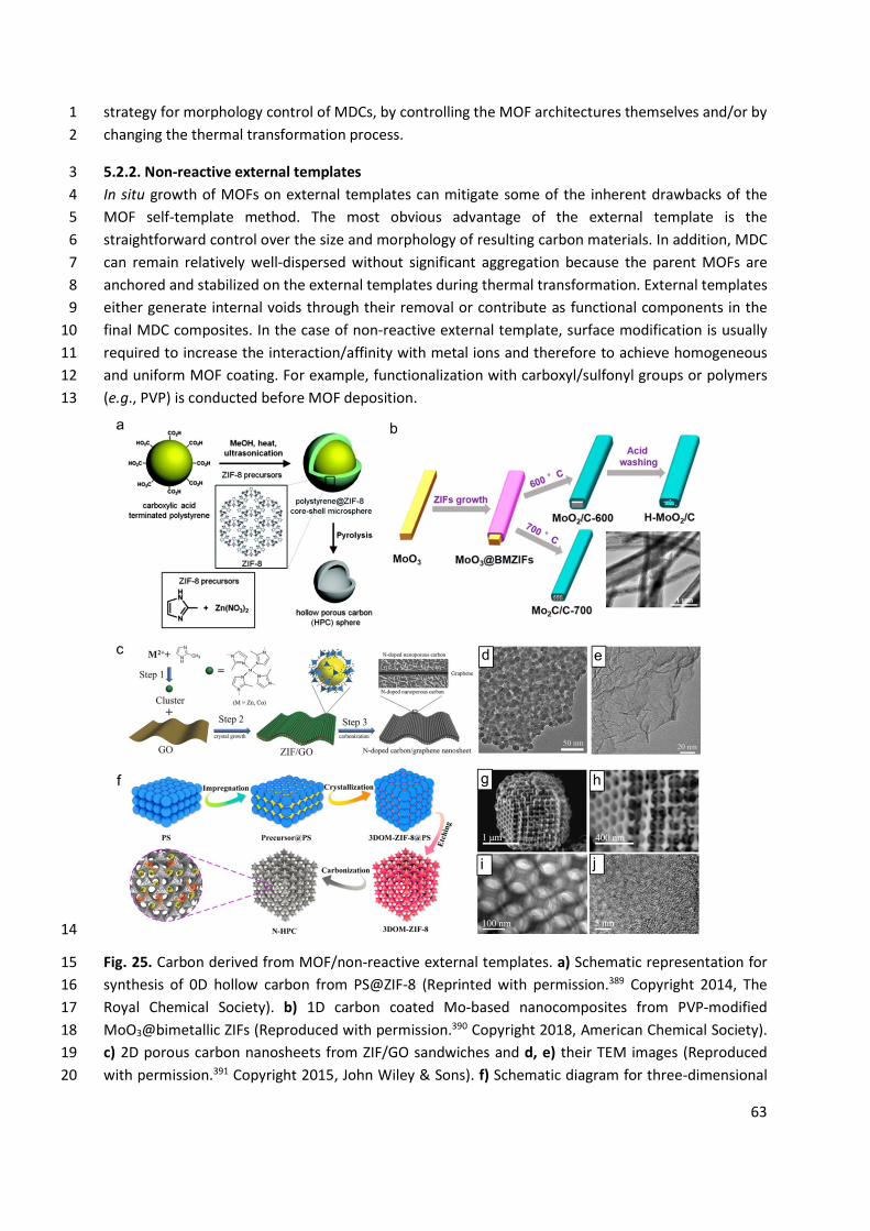
63
strategy for morphology control of MDCs, by controlling the MOF architectures themselves and/or by 1 changing the thermal transformation process. 2
5.2.2. Non-reactive external templates 3 In situ growth of MOFs on external templates can mitigate some of the inherent drawbacks of the 4 MOF self-template method. The most obvious advantage of the external template is the 5 straightforward control over the size and morphology of resulting carbon materials. In addition, MDC 6 can remain relatively well-dispersed without significant aggregation because the parent MOFs are 7 anchored and stabilized on the external templates during thermal transformation. External templates 8 either generate internal voids through their removal or contribute as functional components in the 9 final MDC composites. In the case of non-reactive external template, surface modification is usually 10 required to increase the interaction/affinity with metal ions and therefore to achieve homogeneous 11 and uniform MOF coating. For example, functionalization with carboxyl/sulfonyl groups or polymers 12 (e.g., PVP) is conducted before MOF deposition. 13
14
Fig. 25. Carbon derived from MOF/non-reactive external templates. a) Schematic representation for 15 synthesis of 0D hollow carbon from PS@ZIF-8 (Reprinted with permission.389 Copyright 2014, The 16 Royal Chemical Society). b) 1D carbon coated Mo-based nanocomposites from PVP-modified 17 MoO3@bimetallic ZIFs (Reproduced with permission.390 Copyright 2018, American Chemical Society). 18 c) 2D porous carbon nanosheets from ZIF/GO sandwiches and d, e) their TEM images (Reproduced 19 with permission.391 Copyright 2015, John Wiley & Sons). f) Schematic diagram for three-dimensional 20
64
ordered macroporous ZIF-8 single crystal-derived nitrogen-doped hierarchical porous carbon and 1 corresponding SEM g, h) and TEM i, j) images at different magnification (Reprinted with 2 permission.392 Copyright 2019, American Chemical Society). 3
Zero-dimensional carbons: Typically, carboxylate (or PVP)-terminated poly(styrene) (PS) beads389 4 were mixed with a solution of metal ions/organic ligands to obtain core-shell PS@MOF microspheres 5 (Fig. 25a). Surface carboxyl groups interacted with metal ions and initiated the growth of MOFs. The 6 resulting PS@MOF hybrids were subjected to carbonization under inert gas atmosphere, during 7 which the MOF shell transformed to porous carbon and the PS core decomposed to form hollow 8 interiors. Several PS@ZIF-8,389, 393 PS@ZIF-67,394 PS@MIL-101/ZIF67395 were used for preparation of 9 hollow carbon spheres with or without metal nanoparticles embedded in the carbon shell. 10 Interestingly, fast pyrolysis of PS@ZIF-67 at rapid heating rate (> 5 °C min-1) yielded “single-holed” 11 hollow carbon spheres.394 Thermal decomposition of PS core generated a strong hydrocarbon gas 12 outflux which created a large single hole in each shell. Zhang et al.395 prepared MIL-101/ZIF-67 13 composites shells on PS spheres (PS@MIL-101/ZIF-67) by functionalizing the surfaces of both PS 14 spheres and MIL-101(Fe) nanoparticles with PVP. Thus, the preformed secondary MIL-101 could be 15 homogeneously distributed within the dual-MOF nanoshells. The following pyrolysis produced CoFe 16 alloy@N-doped hollow carbon spheres. 17
18 One-dimensional carbons: 1D template-directed growth of MOFs and their transformation to 1D 19
carbon nanofibers and hollow nanotubes were demonstrated. Yu and coworkers396 utilized ultrathin 20 tellurium nanowires (TeNWs) as hard templates to induce in situ growth and assembly of ZIF-8. 21 Without surface modification, TeNWs were directly immersed in methanolic Zn2+/2-methylimidazole 22 (Hmim) solution at ambient temperature, leading to formation of TeNWs@ZIF-8. The concentrations 23 of TeNWs and reactants were precisely controlled to inhibit solution phase growth of bulk ZIF-8. 24 Porous carbon tubules were obtained after pyrolysis at 1000 °C, during which TeNWs were 25 completely vaporized to form hollow interiors. ZIF-8 derived carbons can also be grown on CNTs.397 26 For controllable ZIF-8 deposition, CNTs were treated with a mixture of nitric acid and sulfuric acid at 27 80 °C to generate the surface carboxylic groups which serve as nucleation sites for ZIF-8 growth. 28 Subsequent pyrolysis at 1000 °C yielded N-doped porous carbons/CNT with controllable large surface 29 area. By using PVP-modified MoO3 nanorods as templates, Tian et al.390 synthesized a series of 1D 30 Mo-based carbon nanorods and nanotubes (Fig. 25b). Amide carbonyl groups of PVP can form weak 31 coordination interactions with metal ions in solution and allow uniform ZIF coating on MoO3 32 nanorods. Controlled pyrolysis at different temperature resulted in either carbothermal reduction to 33 form MoO2/C or reaction with carbon to form Mo2C/C nanorods. The inner MoO2 species were 34 dissolved and dispersed into the porous carbon matrix by HCl washing, leading to formation of 35 hollow MoO2/C nanotubes. 36
37 Two-dimensional carbons: Scalable synthesis of high quality 2D MOFs have been considered as a 38
difficult task and thus only a few 2D MOFs are available for preparation of MDCs so far. This problem 39 can be largely alleviated by using 2D external templates. Graphene has been most extensively used 40 as 2D template because of its excellent thermal, electrical and mechanical properties. As nicely 41 reviewed by Zheng et al.398 and Liu et al.399, a wide variety of MOF/graphene composites have been 42 prepared to combine the advantages of individual components. ZIF-derived graphene based N-doped 43
65
porous carbon was prepared by the in situ growth of ZIF-8 on graphene oxide (GO) sheets.400 PVP 1 functionalization facilitated the uniform nucleation of ZIF-8, resulting in formation of the dispersive 2 2D sandwich-like ZIF-8/GO composites. Without the use of PVP, the surface deposition of ZIF-8 was 3 incomplete and inhomogeneous. Excess Hmim ligand was also necessary for the uniform ZIF growth 4 on GO. Finally, thermal annealing of ZIF-8/GO at 800 °C in Ar flow generated N-doped porous carbon 5 sheets. 6
ZIF-8/GO sandwiches can also be prepared by controlling the addition sequence of the precursors 7 without any surface modification of GO (Fig. 25c-e).391 In the proposed synthetic route, GO dispersion 8 was added to Zn ions/Hmim ligands solution where ZIF clusters were already formed. The cluster 9 readily attached to the GO layer due to a strong interaction between metal ions of cluster and the 10 oxygen functional groups from GO. The uniform deposition of clusters and their confined growth to 11 ZIF nanocrystals on GO surface allowed formation of ZIF-8/GO sandwiches with ZIF nanocrystals (20 12 nm) fully covering the GO. ZIF-derived carbon acted as a spacer to alleviate the significant 13 agglomeration of GO during high-temperature treatment. In contrast, when Zn salts in methanol 14 were firstly added to the GO solution, the Zn ions were located both on GO and in the solution 15 because of insufficient numbers of oxygen groups in GO to capture all the Zn ions. This 16 inhomogeneous nucleation resulted in the mixture of discrete ZIF-8 crystals and ZIF-8/GO 17 composites. 18
19 Three-dimensional and hierarchical carbon: 3D carbon arrays, derived from MOF nanowires grown 20
on various conductive substrates (e.g., metal foam/mesh/foil, carbon cloth, and CNT fibers) are the 21 most common examples of external templated materials.401-404 The substrates provide additional 22 functions such as high electronic conductivity, mechanical stability, and flexibility. Such 3D aligned 23 architectures are of particular interest in electrochemical applications, as they can provide large 24 electrochemical surface area which facilitate electrolyte penetration and diffusion of ionic species, 25 and avoid the use of extra polymeric binders or conductive additives.405 In 2014, Qiao and 26 coworkers401 fabricated MOF-derived Co3O4/carbon porous nanowire arrays for the first time. Co-27 NDC with a layered crystalline structure was directly grown on Cu foil through a hydrothermal 28 reaction at 80 °C for 20 h, and then converted to Co3O4/carbon hybrid arrays with high surface area 29 (251 m2 g-1) and large carbon content (52.1 wt%) via pyrolysis at 600 °C under a N2 atmosphere. 30 Inspired by this pioneering work, researchers have developed a wide variety of 3D carbon-based 31 arrays by employing different combinations of substrates and MOFs.402-404 Instead of arrays, surface-32 mounted MOF (SURMOF), typical MOF thin films prepared by layer-by-layer growth process, was 33 employed as precursor for 3D hierarchical carbon.406 A ZIF-67 thin film was grown on hydroxyl-group-34 terminated 3D macroporous melamine sponge and then converted to vertically aligned N-doped 35 CNTs via pyrolysis at various temperature 700-1000 °C. 36
Preformed MOFs are also promising external templates that enrich the possible particle 37 morphologies of MDCs. Different from typical MOF-on-MOF epitaxial growth, PVP-modified MOFs 38 can be directly integrated with other MOFs via in situ assembly and growth. Guan et al.407 introduced 39 PVP-functionalized MIL-88B (Fe) nanorods into the reactant solution of ZIF-8, and obtained uniform 40 MIL-88B@ZIF-8 particles in which a number of 1D MIL-88B nanorods were co-assembled and 41 encapsulated in ZIF-8 polyhedron (i.e., MOF-in-MOF). This dual-MOF with tailored morphologies and 42 compositions enabled preparation of hierarchically structured Fe3C@N-CNT assemblies confined in a 43 porous carbon matrix. 44
66
Shen et al.408 developed a novel approach toward single-crystal ordered macroporous ZIF-8 (Fig. 1 25f). ZIF-8 precursors (Zn salt and Hmim) were filled into 3D ordered PS sphere-monoliths, and then 2 soaked in CH3OH/NH3·H2O mixed solvent. NH3·H2O induced rapid crystallization of the precursors 3 while CH3OH stabilized the precursors and adjusted the balance between nucleation versus growth of 4 ZIF-8. 3D-ordered macroporous (3DOM) ZIF-8 was liberated from PS templates by repeated soaking 5 in tetrahydrofuran. PS templates imposed unique shaping and templating effects which guided the 6 morphological evolution of 3DOM-ZIF-8 into a tetrakaidekahedron, in contrast to typical rhombic 7 dodecahedra. In the following work, Zhou et al.392 reported 3DOM-ZIF-8-derived hierarchically 8 porous N-doped carbons as high performance anode materials in potassium ion battery (Fig. 25g-j). 9
10 Challenges and opportunities: Non-reactive external template methods usually rely on time-11
consuming and laborious multi-step procedures, including preparation of templates (sometimes their 12 bottom-up assembly into specific shape), surface modification, MOF deposition, carbonization, and 13 template removal (if necessary). Another challenge in this process is the uniform MOF deposition 14 with a controlled thickness. Non-reactive external templates lack the interaction sites that can tightly 15 bind the metal ions. Part of adsorbed metal ions can diffuse into the ligand solution to form bulk 16 MOFs. Thus, it is difficult to confine heterogeneous growth on the surface of templates exclusively. 17 To date, only a few MOFs can be directly coated on the templates and their detailed growth 18 mechanism is not fully understood yet. Thus, the exploration of new synthetic approaches for direct 19 construction of MOF on external templates will be the important subject of future research. In 20 addition, development of new templates with predesigned morphologies and multi-level hierarchical 21 structures (e.g., reactive external templates) is of urgent importance. 22
23 5.2.3. Reactive external templates 24 Pre-shaped, solid state MOs can be transformed into morphology conserved carbons via MOF as 25 intermediate precursors (i.e., reactive external template method or solid-to-MOF-to-carbon 26 pathway).259 Different from typically used solvent-soluble metal salts, the solvent-insoluble solid 27 precursors can perform multiple roles in MOF/carbon synthesis. (1) Architecture directing agents 28 (templates): the morphologies of solid precursors are replicated to the derived MOF and the final 29 carbon materials. (2) Cation reservoirs (metal ion source): solid precursors provide metal ions by 30 slowly dissolving themselves with the assistance of solvents and organic ligands under specific 31 condition, or directly react with organic ligands in solvent-free conditions. Thus, additional metal ion 32 source is not needed. (3) Specific reaction sites for heterogeneous nucleation: the growth of 33 MOF/carbon is localized/confined on the surface of solid precursors. Tedious surface modification 34 steps typically needed in non-reactive external template methods are no longer required. (4) 35 Functional components enhancing physical/chemical properties of the final carbon products. Typical 36 synthesis procedures consist of mainly three steps: preparation of shaped-metal oxides, conversion 37 to desired MOFs by reacting with organic ligands, and thermal transformation into the carbon or 38 carbon-based composites. 39
The key advantage of the reactive template method (e.g., MOs as self-sacrificing templates) lies in 40 its ability to create complex morphologies with multiple levels of structural hierarchies. There are a 41 wide variety of well-established approaches for controlling morphologies of MOs from nano- to 42 micro- to macro-scopic length scales (refer to section 3).210, 211, 409-414 In addition, the MOs can be 43 directly grown onto various functional substrates and host materials, and pre-installed on specific 44
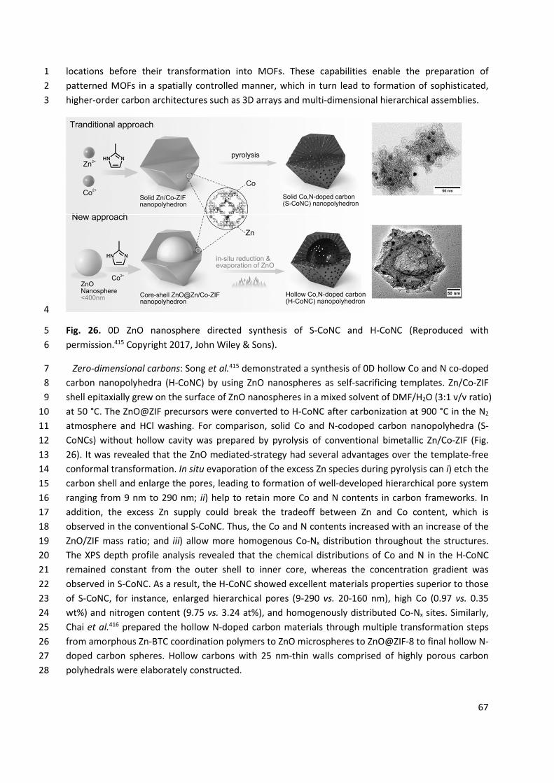
67
locations before their transformation into MOFs. These capabilities enable the preparation of 1 patterned MOFs in a spatially controlled manner, which in turn lead to formation of sophisticated, 2 higher-order carbon architectures such as 3D arrays and multi-dimensional hierarchical assemblies. 3
4
Fig. 26. 0D ZnO nanosphere directed synthesis of S-CoNC and H-CoNC (Reproduced with 5 permission.415 Copyright 2017, John Wiley & Sons). 6
Zero-dimensional carbons: Song et al.415 demonstrated a synthesis of 0D hollow Co and N co-doped 7 carbon nanopolyhedra (H-CoNC) by using ZnO nanospheres as self-sacrificing templates. Zn/Co-ZIF 8 shell epitaxially grew on the surface of ZnO nanospheres in a mixed solvent of DMF/H2O (3:1 v/v ratio) 9 at 50 °C. The ZnO@ZIF precursors were converted to H-CoNC after carbonization at 900 °C in the N2 10 atmosphere and HCl washing. For comparison, solid Co and N-codoped carbon nanopolyhedra (S-11 CoNCs) without hollow cavity was prepared by pyrolysis of conventional bimetallic Zn/Co-ZIF (Fig. 12 26). It was revealed that the ZnO mediated-strategy had several advantages over the template-free 13 conformal transformation. In situ evaporation of the excess Zn species during pyrolysis can i) etch the 14 carbon shell and enlarge the pores, leading to formation of well-developed hierarchical pore system 15 ranging from 9 nm to 290 nm; ii) help to retain more Co and N contents in carbon frameworks. In 16 addition, the excess Zn supply could break the tradeoff between Zn and Co content, which is 17 observed in the conventional S-CoNC. Thus, the Co and N contents increased with an increase of the 18 ZnO/ZIF mass ratio; and iii) allow more homogenous Co-Nx distribution throughout the structures. 19 The XPS depth profile analysis revealed that the chemical distributions of Co and N in the H-CoNC 20 remained constant from the outer shell to inner core, whereas the concentration gradient was 21 observed in S-CoNC. As a result, the H-CoNC showed excellent materials properties superior to those 22 of S-CoNC, for instance, enlarged hierarchical pores (9-290 vs. 20-160 nm), high Co (0.97 vs. 0.35 23 wt%) and nitrogen content (9.75 vs. 3.24 at%), and homogenously distributed Co-Nx sites. Similarly, 24 Chai et al.416 prepared the hollow N-doped carbon materials through multiple transformation steps 25 from amorphous Zn-BTC coordination polymers to ZnO microspheres to ZnO@ZIF-8 to final hollow N-26 doped carbon spheres. Hollow carbons with 25 nm-thin walls comprised of highly porous carbon 27 polyhedrals were elaborately constructed. 28
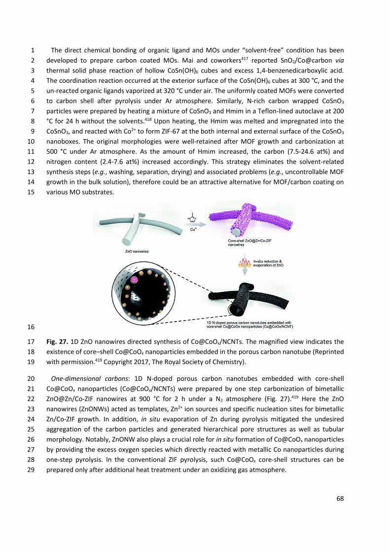
68
The direct chemical bonding of organic ligand and MOs under “solvent-free” condition has been 1 developed to prepare carbon coated MOs. Mai and coworkers417 reported SnO2/Co@carbon via 2 thermal solid phase reaction of hollow CoSn(OH)6 cubes and excess 1,4-benzenedicarboxylic acid. 3 The coordination reaction occurred at the exterior surface of the CoSn(OH)6 cubes at 300 °C, and the 4 un-reacted organic ligands vaporized at 320 °C under air. The uniformly coated MOFs were converted 5 to carbon shell after pyrolysis under Ar atmosphere. Similarly, N-rich carbon wrapped CoSnO3 6 particles were prepared by heating a mixture of CoSnO3 and Hmim in a Teflon-lined autoclave at 200 7 °C for 24 h without the solvents.418 Upon heating, the Hmim was melted and impregnated into the 8 CoSnO3, and reacted with Co2+ to form ZIF-67 at the both internal and external surface of the CoSnO3 9 nanoboxes. The original morphologies were well-retained after MOF growth and carbonization at 10 500 °C under Ar atmosphere. As the amount of Hmim increased, the carbon (7.5-24.6 at%) and 11 nitrogen content (2.4-7.6 at%) increased accordingly. This strategy eliminates the solvent-related 12 synthesis steps (e.g., washing, separation, drying) and associated problems (e.g., uncontrollable MOF 13 growth in the bulk solution), therefore could be an attractive alternative for MOF/carbon coating on 14 various MO substrates. 15
16
Fig. 27. 1D ZnO nanowires directed synthesis of Co@CoOx/NCNTs. The magnified view indicates the 17 existence of core–shell Co@CoOx nanoparticles embedded in the porous carbon nanotube (Reprinted 18 with permission.419 Copyright 2017, The Royal Society of Chemistry). 19
One-dimensional carbons: 1D N-doped porous carbon nanotubes embedded with core-shell 20 Co@CoOx nanoparticles (Co@CoOx/NCNTs) were prepared by one step carbonization of bimetallic 21 ZnO@Zn/Co-ZIF nanowires at 900 °C for 2 h under a N2 atmosphere (Fig. 27).419 Here the ZnO 22 nanowires (ZnONWs) acted as templates, Zn2+ ion sources and specific nucleation sites for bimetallic 23 Zn/Co-ZIF growth. In addition, in situ evaporation of Zn during pyrolysis mitigated the undesired 24 aggregation of the carbon particles and generated hierarchical pore structures as well as tubular 25 morphology. Notably, ZnONW also plays a crucial role for in situ formation of Co@CoOx nanoparticles 26 by providing the excess oxygen species which directly reacted with metallic Co nanoparticles during 27 one-step pyrolysis. In the conventional ZIF pyrolysis, such Co@CoOx core-shell structures can be 28 prepared only after additional heat treatment under an oxidizing gas atmosphere. 29
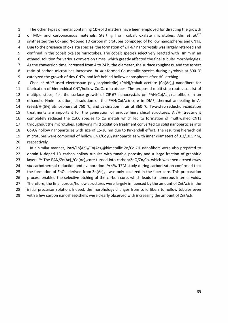
69
The other types of metal containing 1D-solid matters have been employed for directing the growth 1 of MOF and carbonaceous materials. Starting from cobalt oxalate microtubes, Ahn et al.420 2 synthesized the Co- and N-doped 1D carbon microtubes composed of hollow nanospheres and CNTs. 3 Due to the presence of oxalate species, the formation of ZIF-67 nanocrystals was largely retarded and 4 confined in the cobalt oxalate microtubes. The cobalt species selectively reacted with Hmim in an 5 ethanol solution for various conversion times, which greatly affected the final tubular morphologies. 6 As the conversion time increased from 4 to 24 h, the diameter, the surface roughness, and the aspect 7 ratio of carbon microtubes increased. In situ formed Co metallic species during pyrolysis at 800 °C 8 catalyzed the growth of tiny CNTs, and left behind hollow nanospheres after HCl etching. 9
Chen et al.421 used electrospun poly(acrylonitrile) (PAN)/cobalt acetate (Co(Ac)2) nanofibers for 10 fabrication of hierarchical CNT/hollow Co3O4 microtubes. The proposed multi-step routes consist of 11 multiple steps, i.e., the surface growth of ZIF-67 nanocrystals on PAN/Co(Ac)2 nanofibers in an 12 ethanolic Hmim solution, dissolution of the PAN/Co(Ac)2 core in DMF, thermal annealing in Ar 13 (95%)/H2(5%) atmosphere at 750 °C, and calcination in air at 360 °C. Two-step reduction-oxidation 14 treatments are important for the generation of unique hierarchical structures. Ar/H2 treatment 15 completely reduced the CoOx species to Co metals which led to formation of multiwalled CNTs 16 throughout the microtubes. Following mild oxidation treatment converted Co solid nanoparticles into 17 Co3O4 hollow nanoparticles with size of 15-30 nm due to Kirkendall effect. The resulting hierarchical 18 microtubes were composed of hollow CNT/Co3O4 nanoparticles with inner diameters of 3.2/10.5 nm, 19 respectively. 20
In a similar manner, PAN/Zn(Ac)2/Co(Ac)2@bimetallic Zn/Co-ZIF nanofibers were also prepared to 21 obtain N-doped 1D carbon hollow tubules with tunable porosity and a large fraction of graphitic 22 layers.422 The PAN/Zn(Ac)2/Co(Ac)2 core turned into carbon/ZnO/ZnxCo, which was then etched away 23 via carbothermal reduction and evaporation. In situ TEM study during carbonization confirmed that 24 the formation of ZnO - derived from Zn(Ac)2 - was only localized in the fiber core. This preparation 25 process enabled the selective etching of the carbon core, which leads to numerous internal voids. 26 Therefore, the final porous/hollow structures were largely influenced by the amount of Zn(Ac)2 in the 27 initial precursor solution. Indeed, the morphology changes from solid fibers to hollow tubules even 28 with a few carbon nanosheet-shells were clearly observed with increasing the amount of Zn(Ac)2. 29
70
1
Fig. 28. 2D ZnCo-LDH derived synthesis of 2D ZIF and carbon flakes. a) Schematic illustration of the 2 synthesis of ZIF networks. SEM images of b) ZnCo-LDH-1, c) ZnCo-ZIF-1-4h, and d) ZnCo-ZIF-1. e) 3 Schematic illustration of the pore formation mechanism. SEM images of f, g) 2D honeycomb-like 4 carbon flakes (Reproduced with permission.423 Copyright 2018, John Wiley & Sons). 5
Two-dimensional carbons: 2D porous ZnO nanosheet was the first choice to demonstrate the 6 preparation of 2D ZIF-8 and carbon materials with hierarchical porosity.424 On the other hand, 7 layered double-metal hydroxide (LDH) and metal hydroxide have great potential as 2D scaffolds and 8 self-sacrificial metal ion sources for in situ MOF growth as well. LDHs inherently possess a plentiful 9 amount of coordinatively unsaturated metal sites on their surface, providing specific anchoring sites 10 for MOF deposition. Indeed, in situ ZIF-67 deposition to CoAl-LDH nanoplatelets was demonstrated 11 by Wei and coworkers.425 In their contribution, however, surface Co ions in CoAl-LDH served as 12 preferential nucleation sites only and additional Co source was needed for controllable ZIF-67 13 growth. 14
The use of LDH as true reactive external template was demonstrated by Yamauchi and coworkers423 15 for preparation of 2D honeycomb-like carbon flakes. ZnCo-LDHs with a lateral size/thickness of 1 16 μm/10 nm were dispersed in mixed solvent of DMF/H2O (9:1 v/v ratio), and subsequently underwent 17 transformation to ZnCo-ZIFs through the reaction with Hmim at 50 °C. ZIF polyhedrals with a 18 diameter of 100 nm began to grow on the flat surface of ZnCo-LDH after 4 h, and they formed 19 densely packed flake-like networks after 8 h (Fig. 28a-d). The Zn/Co molar ratio in parent ZnCo-LDH 20 was comparable to that in daughter ZnCo-ZIF, suggesting the homogeneous reaction between 21 dissolved metal ions and Hmim. 2D-interconnected carbon flakes with abundant honeycomb-like 22 macropores were produced via carbonization at 800 °C and acid etching, during which ZnCo-ZIF 23 suffered from inhomogeneous framework shrinkage (Fig. 28e-g). This shrinkage is closely related to 24 tightly packed networks of ZIF polyhedrons. The connected edges that intimately adhere with 25 adjacent polyhedrons were stable and well-retained during carbonization. In contrast, the exposed 26 single edges without intimate contact with the others were unstable and shrank toward the edge 27 sides, thereby leading to formation of honeycomb-like macropores. This formation strategy was also 28 applicable to ZnCo-LDH with a different molar ratio and other layered metal hydroxide 29
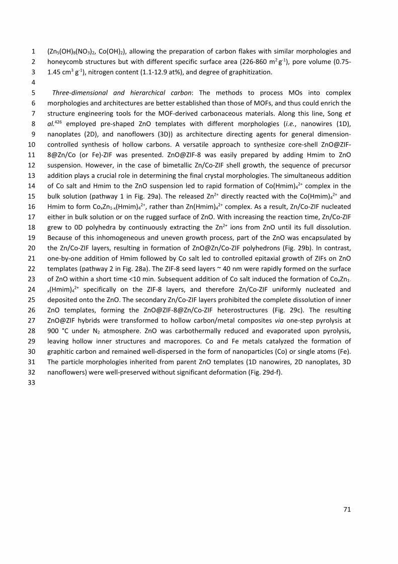
71
(Zn5(OH)8(NO3)2, Co(OH)2), allowing the preparation of carbon flakes with similar morphologies and 1 honeycomb structures but with different specific surface area (226-860 m2 g-1), pore volume (0.75-2 1.45 cm3 g-1), nitrogen content (1.1-12.9 at%), and degree of graphitization. 3
4 Three-dimensional and hierarchical carbon: The methods to process MOs into complex 5
morphologies and architectures are better established than those of MOFs, and thus could enrich the 6 structure engineering tools for the MOF-derived carbonaceous materials. Along this line, Song et 7 al.426 employed pre-shaped ZnO templates with different morphologies (i.e., nanowires (1D), 8 nanoplates (2D), and nanoflowers (3D)) as architecture directing agents for general dimension-9 controlled synthesis of hollow carbons. A versatile approach to synthesize core-shell ZnO@ZIF-10 8@Zn/Co (or Fe)-ZIF was presented. ZnO@ZIF-8 was easily prepared by adding Hmim to ZnO 11 suspension. However, in the case of bimetallic Zn/Co-ZIF shell growth, the sequence of precursor 12 addition plays a crucial role in determining the final crystal morphologies. The simultaneous addition 13 of Co salt and Hmim to the ZnO suspension led to rapid formation of Co(Hmim)4
2+ complex in the 14 bulk solution (pathway 1 in Fig. 29a). The released Zn2+ directly reacted with the Co(Hmim)4
2+ and 15 Hmim to form CoxZn1-x(Hmim)4
2+, rather than Zn(Hmim)42+ complex. As a result, Zn/Co-ZIF nucleated 16
either in bulk solution or on the rugged surface of ZnO. With increasing the reaction time, Zn/Co-ZIF 17 grew to 0D polyhedra by continuously extracting the Zn2+ ions from ZnO until its full dissolution. 18 Because of this inhomogeneous and uneven growth process, part of the ZnO was encapsulated by 19 the Zn/Co-ZIF layers, resulting in formation of ZnO@Zn/Co-ZIF polyhedrons (Fig. 29b). In contrast, 20 one-by-one addition of Hmim followed by Co salt led to controlled epitaxial growth of ZIFs on ZnO 21 templates (pathway 2 in Fig. 28a). The ZIF-8 seed layers ~ 40 nm were rapidly formed on the surface 22 of ZnO within a short time <10 min. Subsequent addition of Co salt induced the formation of CoxZn1-23 x(Hmim)4
2+ specifically on the ZIF-8 layers, and therefore Zn/Co-ZIF uniformly nucleated and 24 deposited onto the ZnO. The secondary Zn/Co-ZIF layers prohibited the complete dissolution of inner 25 ZnO templates, forming the ZnO@ZIF-8@Zn/Co-ZIF heterostructures (Fig. 29c). The resulting 26 ZnO@ZIF hybrids were transformed to hollow carbon/metal composites via one-step pyrolysis at 27 900 °C under N2 atmosphere. ZnO was carbothermally reduced and evaporated upon pyrolysis, 28 leaving hollow inner structures and macropores. Co and Fe metals catalyzed the formation of 29 graphitic carbon and remained well-dispersed in the form of nanoparticles (Co) or single atoms (Fe). 30 The particle morphologies inherited from parent ZnO templates (1D nanowires, 2D nanoplates, 3D 31 nanoflowers) were well-preserved without significant deformation (Fig. 29d-f). 32
33
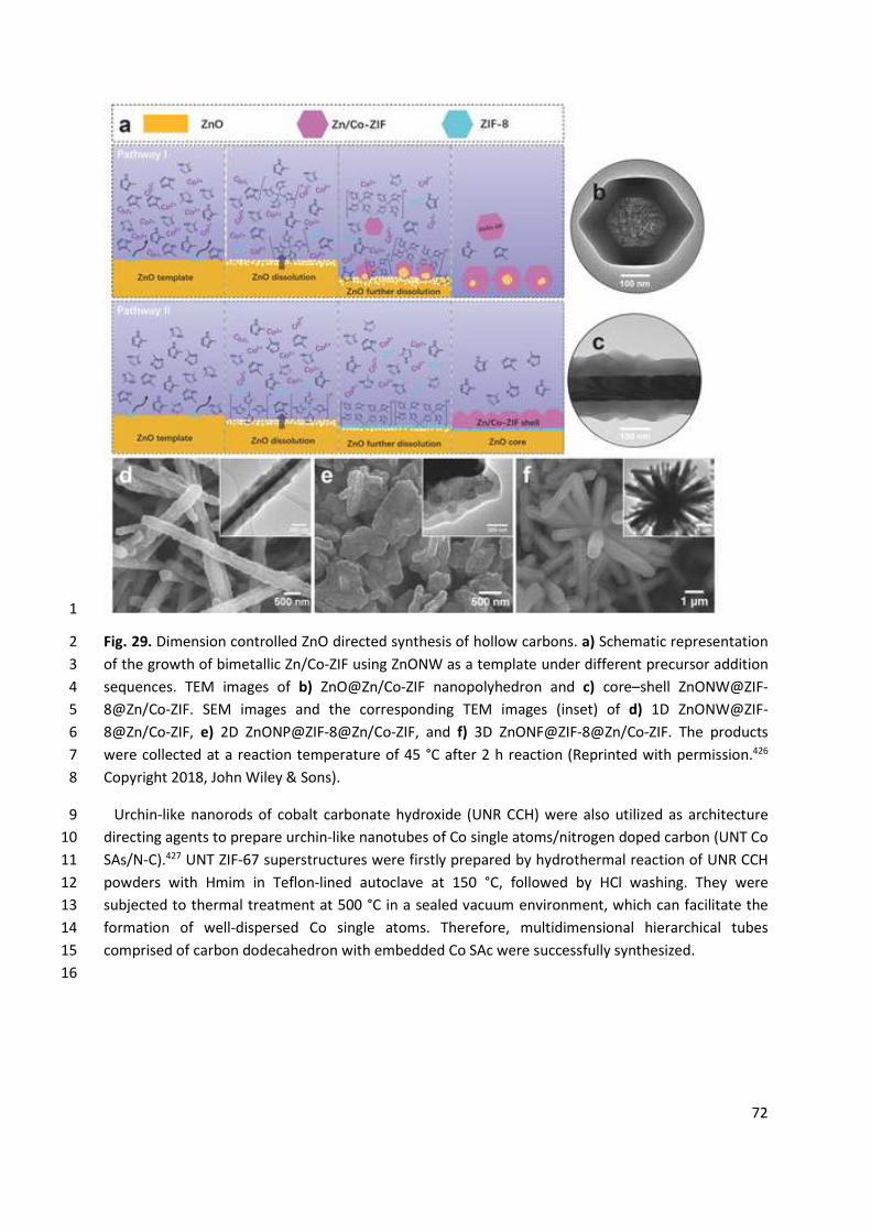
72
1
Fig. 29. Dimension controlled ZnO directed synthesis of hollow carbons. a) Schematic representation 2 of the growth of bimetallic Zn/Co-ZIF using ZnONW as a template under different precursor addition 3 sequences. TEM images of b) ZnO@Zn/Co-ZIF nanopolyhedron and c) core–shell ZnONW@ZIF-4 8@Zn/Co-ZIF. SEM images and the corresponding TEM images (inset) of d) 1D ZnONW@ZIF-5 8@Zn/Co-ZIF, e) 2D ZnONP@ZIF-8@Zn/Co-ZIF, and f) 3D ZnONF@ZIF-8@Zn/Co-ZIF. The products 6 were collected at a reaction temperature of 45 °C after 2 h reaction (Reprinted with permission.426 7 Copyright 2018, John Wiley & Sons). 8
Urchin-like nanorods of cobalt carbonate hydroxide (UNR CCH) were also utilized as architecture 9 directing agents to prepare urchin-like nanotubes of Co single atoms/nitrogen doped carbon (UNT Co 10 SAs/N-C).427 UNT ZIF-67 superstructures were firstly prepared by hydrothermal reaction of UNR CCH 11 powders with Hmim in Teflon-lined autoclave at 150 °C, followed by HCl washing. They were 12 subjected to thermal treatment at 500 °C in a sealed vacuum environment, which can facilitate the 13 formation of well-dispersed Co single atoms. Therefore, multidimensional hierarchical tubes 14 comprised of carbon dodecahedron with embedded Co SAc were successfully synthesized. 15
16
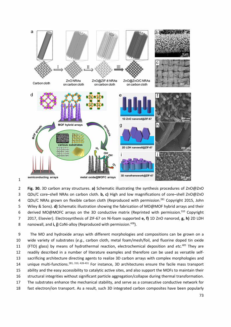
73
1
Fig. 30. 3D carbon array structures. a) Schematic illustrating the synthesis procedures of ZnO@ZnO 2 QDs/C core–shell NRAs on carbon cloth. b, c) High and low magnifications of core–shell ZnO@ZnO 3 QDs/C NRAs grown on flexible carbon cloth (Reproduced with permission.281 Copyright 2015, John 4 Wiley & Sons). d) Schematic illustration showing the fabrication of MO@MOF hybrid arrays and their 5 derived MO@MOFC arrays on the 3D conductive matrix (Reprinted with permission.310 Copyright 6 2017, Elsevier). Electrosynthesis of ZIF-67 on Ni-foam supported e, f) 1D ZnO nanorod, g, h) 2D LDH 7 nanowall, and i, j) CoNi-alloy (Reproduced with permission.428). 8
The MO and hydroxide arrays with different morphologies and compositions can be grown on a 9 wide variety of substrates (e.g., carbon cloth, metal foam/mesh/foil, and fluorine doped tin oxide 10 (FTO) glass) by means of hydrothermal reaction, electrochemical deposition and etc.405 They are 11 readily described in a number of literature examples and therefore can be used as versatile self-12 sacrificing architecture directing agents to realize 3D carbon arrays with complex morphologies and 13 unique multi-functions.281, 310, 428-431 For instance, 3D architectures ensure the facile mass transport 14 ability and the easy accessibility to catalytic active sites, and also support the MOFs to maintain their 15 structural integrities without significant particle aggregation/collapse during thermal transformation. 16 The substrates enhance the mechanical stability, and serve as a consecutive conductive network for 17 fast electron/ion transport. As a result, such 3D integrated carbon composites have been popularly 18
74
adopted as binder-free, conductive additive-free self-supported electrodes in energy storage and 1 conversion devices, such as flexible supercapacitor, electrochemical water splitting, Zn-air battery, Li 2 and Na ion battery.281, 310, 405, 428-431 3
In 2015, Duan and coworkers281 described the integration of metal oxide array and conductive 4 substrate for the first time to develop ZnO@ZnO quantum dots (QD)/C core-shell nanorod arrays 5 (NRA) on flexible carbon cloth (Fig. 30a-c). ZnO NRAs with the diameter/length of 300 nm/4.5-7 μm 6 were vertically grown on carbon cloth by hydrothermal deposition route, and further served as 7 sacrificial template and Zn ion source for ZIF-8 shell growth. They reacted with Hmim ligand in a 8 mixed solvent of DMF/H2O (3:1 v/v ratio) at 70 °C, yielding ZnO@ZIF-8 NRAs. Thermal annealing 9 under N2 gas flow at 650 °C led to formation of ZnO@ZnO QD/C with multi-dimensional hierarchical 10 architectures. Starting from identical ZnO@ZIF-8 NRA on carbon cloth, the same group also 11 fabricated N-doped carbon bubbles supported on carbon tube arrays via catalytic deposition of 12 ethanol and reduction-evaporation process.429 The ethanol vapour penetrated the ZIF-8 shell to 13 access the surface of ZnO core where the catalytic ethanol decomposition-carbon deposition 14 occurred at high temperature (500-800 °C). During this process the continuous ZIF-8 shell layer 15 cracked into discrete ZIF-8 nanocrystals. Following H2/Ar gas reduction at 800 °C rapidly generated 16 nano-sized Zn metals, which were completely removed by evaporation without additional acid 17 etching. This process directly converted the ZnO@C@ZIF-8 to hollow carbon tubes@N-doped carbon 18 bubbles. Yang et al.430 further employed the ZnO@ZIF-8 NRAs as versatile precursors for fabrication 19 of other types of hybrid materials with tailored chemical structures and compositions. 20 ZnO@C@CoNi-LDH arrays were prepared by pyrolysis of ZnO@ZIF-8 and subsequent electrochemical 21 deposition of CoNi-LDH nanoplatelets on the external surface of ZnO@C. In parallel, Fe2O3@C NRAs 22 were synthesized by converting ZnO@ZIF-8 to Fe(OH)3@ZIF-Fe through Zn-Fe cationic exchange in 23 aqueous solution at room temperature, followed by pyrolysis in N2 atmosphere at 450 °C. The 24 resulting ZnO@C@CoNi-LDH and Fe2O3@C were used as self-supported electrodes for fabrication of 25 asymmetric flexible all-solid-state supercapacitors. 26
Solid cobalt materials (cobalt carbonate hydroxide (CCH) and cobalt oxide) were integrated with 27 conductive metal substrates to prepare similar 3D architectures having different chemical 28 compositions. ZIF-67 was directly grown on well-aligned CCH nanorods in Hmim/H2O/triethylamine 29 solution. Subsequent treatments of oxidation, sulfurization, carbonization and phosphorization gave 30 rise to hierarchically structured Co3O4@X composites (where X = Co3O4, CoS, C, and CoP).333 Huang et 31 al.432 modified this procedure to prepare CoP nanoarray wrapped by N, P-doped carbon on Ti foil. 32 Instead of CCH arrays, Wang et al.433 used hierarchical CoO nanowires on Ni foam to synthesize 33 CoO@ZIF-67 and in turn CoO@N-doped carbons. 34
Jiang and coworkers310 demonstrated fabrication of a series of well-defined MOF arrays/carbons 35 grown onto various substrates (Fig. 30d). Different kinds of solid metal arrays (CoO, NiO and Cu(OH2) 36 were directly grown on diverse substrates (Ni foam, Cu mesh, Cu foil, and Fe mesh) by a 37 hydrothermal method, then reacted with related organic ligands to form ZIF-67, Co-MOF-74 and 38 HKUST-1. Pyrolysis under N2 gas flow at 500 °C yielded the corresponding metal oxide@carbon on 39 substrates with well-retained 3D array architectures. The authors found that the choice of 40 appropriate solvents and solid metal precursors is critical for controlled MOF growth. For instance, 41 the dissolution of CoO in ethanol is too slow to provide enough Co2+ ions for ZIF-67 formation, while 42 that in water is too fast to confine the ZIF-67 nucleation on CoO nanorods exclusively. Furthermore, 43 the use of Co3O4 instead of CoO only led to poorly defined heterostructures, possibly because of its 44
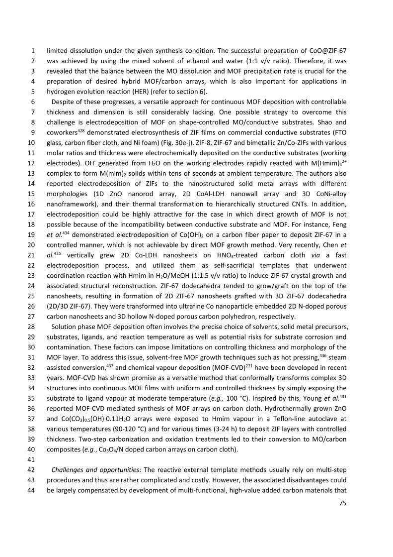
75
limited dissolution under the given synthesis condition. The successful preparation of CoO@ZIF-67 1 was achieved by using the mixed solvent of ethanol and water (1:1 v/v ratio). Therefore, it was 2 revealed that the balance between the MO dissolution and MOF precipitation rate is crucial for the 3 preparation of desired hybrid MOF/carbon arrays, which is also important for applications in 4 hydrogen evolution reaction (HER) (refer to section 6). 5
Despite of these progresses, a versatile approach for continuous MOF deposition with controllable 6 thickness and dimension is still considerably lacking. One possible strategy to overcome this 7 challenge is electrodeposition of MOF on shape-controlled MO/conductive substrates. Shao and 8 coworkers428 demonstrated electrosynthesis of ZIF films on commercial conductive substrates (FTO 9 glass, carbon fiber cloth, and Ni foam) (Fig. 30e-j). ZIF-8, ZIF-67 and bimetallic Zn/Co-ZIFs with various 10 molar ratios and thickness were electrochemically deposited on the conductive substrates (working 11 electrodes). OH- generated from H2O on the working electrodes rapidly reacted with M(Hmim)4
2+ 12 complex to form M(mim)2 solids within tens of seconds at ambient temperature. The authors also 13 reported electrodeposition of ZIFs to the nanostructured solid metal arrays with different 14 morphologies (1D ZnO nanorod array, 2D CoAl-LDH nanowall array and 3D CoNi-alloy 15 nanoframework), and their thermal transformation to hierarchically structured CNTs. In addition, 16 electrodeposition could be highly attractive for the case in which direct growth of MOF is not 17 possible because of the incompatibility between conductive substrate and MOF. For instance, Feng 18 et al.434 demonstrated electrodeposition of Co(OH)2 on a carbon fiber paper to deposit ZIF-67 in a 19 controlled manner, which is not achievable by direct MOF growth method. Very recently, Chen et 20 al.435 vertically grew 2D Co-LDH nanosheets on HNO3-treated carbon cloth via a fast 21 electrodeposition process, and utilized them as self-sacrificial templates that underwent 22 coordination reaction with Hmim in H2O/MeOH (1:1.5 v/v ratio) to induce ZIF-67 crystal growth and 23 associated structural reconstruction. ZIF-67 dodecahedra tended to grow/graft on the top of the 24 nanosheets, resulting in formation of 2D ZIF-67 nanosheets grafted with 3D ZIF-67 dodecahedra 25 (2D/3D ZIF-67). They were transformed into ultrafine Co nanoparticle embedded 2D N-doped porous 26 carbon nanosheets and 3D hollow N-doped porous carbon polyhedron, respectively. 27
Solution phase MOF deposition often involves the precise choice of solvents, solid metal precursors, 28 substrates, ligands, and reaction temperature as well as potential risks for substrate corrosion and 29 contamination. These factors can impose limitations on controlling thickness and morphology of the 30 MOF layer. To address this issue, solvent-free MOF growth techniques such as hot pressing,436 steam 31 assisted conversion,437 and chemical vapour deposition (MOF-CVD)271 have been developed in recent 32 years. MOF-CVD has shown promise as a versatile method that conformally transforms complex 3D 33 structures into continuous MOF films with uniform and controlled thickness by simply exposing the 34 substrate to ligand vapour at moderate temperature (e.g., 100 °C). Inspired by this, Young et al.431 35 reported MOF-CVD mediated synthesis of MOF arrays on carbon cloth. Hydrothermally grown ZnO 36 and Co(CO3)0.5(OH)·0.11H2O arrays were exposed to Hmim vapour in a Teflon-line autoclave at 37 various temperatures (90-120 °C) and for various times (3-24 h) to deposit ZIF layers with controlled 38 thickness. Two-step carbonization and oxidation treatments led to their conversion to MO/carbon 39 composites (e.g., Co3O4/N doped carbon arrays on carbon cloth). 40
41 Challenges and opportunities: The reactive external template methods usually rely on multi-step 42
procedures and thus are rather complicated and costly. However, the associated disadvantages could 43 be largely compensated by development of multi-functional, high-value added carbon materials that 44
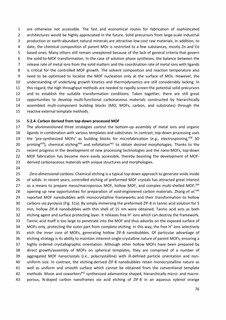
76
are otherwise not accessible. The fast and economical routes for fabrication of sophisticated 1 architectures would be highly appreciated in the future. Solid precursors from large-scale industrial 2 production or earth-abundant natural minerals are attractive low-cost raw materials. In addition, to 3 date, the chemical composition of parent MOs is restricted to a few substances, mostly Zn and Co 4 based ones. Many others still remain unexplored because of the lack of general criteria that govern 5 the solid-to-MOF transformation. In the case of solution phase syntheses, the balance between the 6 release rate of metal ions from the solid matters and the coordination rate of metal ions with ligands 7 is critical for the controlled MOF growth. The solvent composition and reaction temperature also 8 need to be optimized to localize the MOF nucleation only at the surface of MOs. However, the 9 understanding of underlying growth kinetics and thermodynamics are still considerably lacking. In 10 this regard, the high throughput methods are needed to rapidly screen the potential solid precursors 11 and to establish the suitable transformation conditions. Taken together, there are still great 12 opportunities to develop multi-functional carbonaceous materials constructed by hierarchically 13 assembled multi-component building blocks (MO, MOFs, carbon, and substrates) through the 14 reactive external template methods. 15
5.2.4. Carbon derived from top-down processed MOF 16 The aforementioned three strategies control the bottom-up assembly of metal ions and organic 17 ligands in combination with various templates and substrates. In contrast, top-down processing uses 18 the ‘pre-synthesized MOFs’ as building blocks for microfabrication (e.g., electrospinning,438 3D 19 printing439), chemical etching440 and exfoliation441 to obtain desired morphologies. Thanks to the 20 recent progress in the development of new processing technologies and the nano-MOFs, top-down 21 MOF fabrication has become more easily accessible, thereby boosting the development of MOF-22 derived carbonaceous materials with unique structures and morphologies. 23 24
Zero-dimensional carbons: Chemical etching is a typical top-down approach to generate voids inside 25 of solids. In recent years, controlled etching of preformed MOF crystals has attracted great interest 26 as a means to prepare meso/macroporous MOF, hollow MOF, and complex multi-shelled MOF,364 27 opening up new opportunities for preparation of void-engineered carbon materials. Zhang et al.440 28 reported MOF nanobubbles with monocrystalline frameworks and their transformation to hollow 29 carbons via pyrolysis (Fig. 31a). By simply immersing the preformed ZIF-8 in tannic acid solution for 5 30 min, hollow ZIF-8 nanobubbles with thin shell of 15 nm were obtained. Tannic acid acts as both 31 etching agent and surface protecting layer. It releases free H+ ions which can destroy the framework. 32 Tannic acid itself is too large to penetrate into the MOF and thus adsorbs on the exposed surface of 33 MOFs only, protecting the outer part from complete etching. In this way, the free H+ ions selectively 34 etch the inner core of MOFs, generating hollow ZIF-8 nanobubbles. Of particular advantage of 35 etching strategy is its ability to maintain inherent single-crystalline nature of parent MOFs, ensuring a 36 highly ordered crystallographic orientation. Although other hollow MOFs have been prepared by 37 direct growth/assembly of MOFs on spherical templates, they are comprised of a number of 38 aggregated MOF nanocrystals (i.e., polycrystalline) with ill-defined particle orientation and non-39 uniform size. In contrast, the etching-derived ZIF-8 nanobubbles retain monocrystalline nature as 40 well as uniform and smooth surface which cannot be obtained from the conventional template 41 methods. Moon and coworkers442 synthesized adamantine shaped, hierarchically micro- and macro-42 porous, N-doped carbon nanoframes via acid etching of ZIF-8 in an aqueous xylenol orange 43
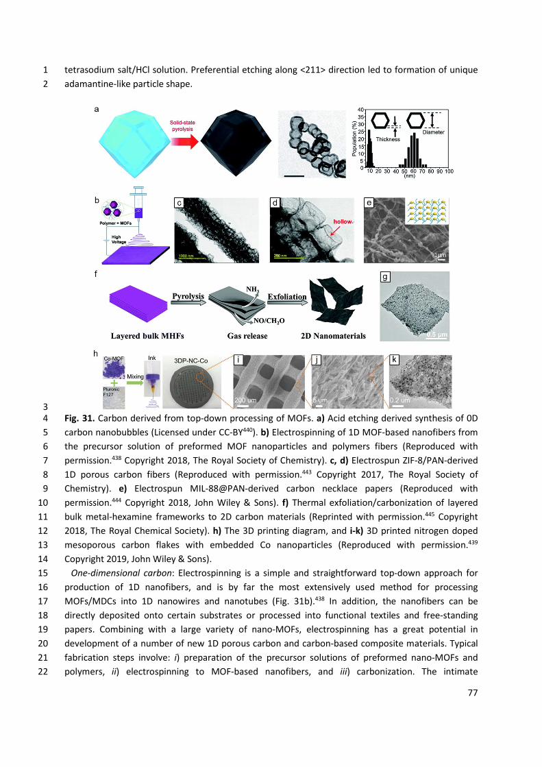
77
tetrasodium salt/HCl solution. Preferential etching along <211> direction led to formation of unique 1 adamantine-like particle shape. 2
3 Fig. 31. Carbon derived from top-down processing of MOFs. a) Acid etching derived synthesis of 0D 4 carbon nanobubbles (Licensed under CC-BY440). b) Electrospinning of 1D MOF-based nanofibers from 5 the precursor solution of preformed MOF nanoparticles and polymers fibers (Reproduced with 6 permission.438 Copyright 2018, The Royal Society of Chemistry). c, d) Electrospun ZIF-8/PAN-derived 7 1D porous carbon fibers (Reproduced with permission.443 Copyright 2017, The Royal Society of 8 Chemistry). e) Electrospun MIL-88@PAN-derived carbon necklace papers (Reproduced with 9 permission.444 Copyright 2018, John Wiley & Sons). f) Thermal exfoliation/carbonization of layered 10 bulk metal-hexamine frameworks to 2D carbon materials (Reprinted with permission.445 Copyright 11 2018, The Royal Chemical Society). h) The 3D printing diagram, and i-k) 3D printed nitrogen doped 12 mesoporous carbon flakes with embedded Co nanoparticles (Reproduced with permission.439 13 Copyright 2019, John Wiley & Sons). 14
One-dimensional carbon: Electrospinning is a simple and straightforward top-down approach for 15 production of 1D nanofibers, and is by far the most extensively used method for processing 16 MOFs/MDCs into 1D nanowires and nanotubes (Fig. 31b).438 In addition, the nanofibers can be 17 directly deposited onto certain substrates or processed into functional textiles and free-standing 18 papers. Combining with a large variety of nano-MOFs, electrospinning has a great potential in 19 development of a number of new 1D porous carbon and carbon-based composite materials. Typical 20 fabrication steps involve: i) preparation of the precursor solutions of preformed nano-MOFs and 21 polymers, ii) electrospinning to MOF-based nanofibers, and iii) carbonization. The intimate 22
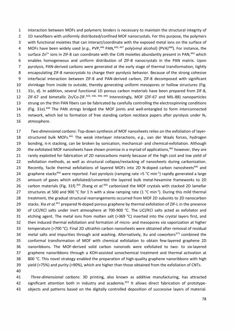
78
interaction between MOFs and polymeric binders is necessary to maintain the structural integrity of 1 1D nanofibers with uniformly distributed/confined MOF nanocrystals. For this purpose, the polymers 2 with functional moieties that can interact/coordinate with the exposed metal ions on the surface of 3 MOFs have been widely used (e.g., PVP,446 PAN,443, 447 poly(vinyl alcohol) (PVA)448). For instance, the 4 surface Zn2+ ions in ZIF-8 can coordinate with the C≡N moie es abundantly present in PAN,443 which 5 enables homogeneous and uniform distribution of ZIF-8 nanocrystals in the PAN matrix. Upon 6 pyrolysis, PAN-derived carbons were generated at the early stage of thermal transformation, tightly 7 encapsulating ZIF-8 nanocrystals to change their pyrolysis behavior. Because of the strong cohesive 8 interfacial interaction between ZIF-8 and PAN-derived carbon, ZIF-8 decomposed with significant 9 shrinkage from inside to outside, thereby generating uniform mesopores or hollow structures (Fig. 10 31c, d). In addition, several functional 1D porous carbon materials have been prepared from ZIF-8, 11 ZIF-67 and bimetallic Zn/Co-ZIF.443, 446, 448, 449 Interestingly, MOF (ZIF-67 and MIL-88) nanoparticles 12 strung on the thin PAN fibers can be fabricated by carefully controlling the electrospinning conditions 13 (Fig. 31e).444 The PAN strings bridged the MOF joints and well-entangled to form interconnected 14 network, which led to formation of free standing carbon necklace papers after pyrolysis under N2 15 atmosphere. 16
Two-dimensional carbons: Top-down synthesis of MOF nanosheets relies on the exfoliation of layer-17 structured bulk MOFs.441 The weak interlayer interactions, e.g., van der Waals forces, hydrogen 18 bonding, π-π stacking, can be broken by sonication, mechanical- and chemical-exfoliation. Although 19 the exfoliated MOF nanosheets have shown promise in a myriad of applications,441 however, they are 20 rarely exploited for fabrication of 2D nanocarbons mainly because of the high cost and low yield of 21 exfoliation methods, as well as structural collapse/restacking of nanosheets during carbonization. 22 Recently, facile thermal exfoliations of layered MOFs into 2D N-doped carbon nanosheets445 and 23 graphene stacks450 were reported. Fast pyrolysis (ramping rate >5 °C min-1) rapidly generated a large 24 amount of gases which exfoliated/converted the layered bulk metal-hexamine frameworks to 2D 25 carbon materials (Fig. 31f).445 Zhang et al.450 carbonized the MOF crystals with stacked 2D lamellar 26 structures at 500 and 900 °C for 1 h with a slow ramping rate (1 °C min-1). During this mild thermal 27 treatment, the gradual structural rearrangements occurred from MOF 2D subunits to 2D nanocarbon 28 stacks. Xia et al.451 prepared N-doped porous graphene by thermal exfoliation of ZIF-L in the presence 29 of LiCl/KCl salts under inert atmosphere at 700-900 °C. The LiCl/KCl salts acted as exfoliator and 30 etching agent. The metal ions from molten salt (>369 °C) inserted into the crystal layers first, and 31 then induced thermal exfoliation and formation of micro- and mesopores via vaporization at higher 32 temperature (>700 °C). Final 2D ultrathin carbon nanosheets were obtained after removal of residual 33 metal salts and impurities through acid washing. Alternatively, Xu and coworkers373 combined the 34 conformal transformation of MOF with chemical exfoliation to obtain few-layered graphene 2D 35 nanoribbons. The MOF-derived solid carbon nanorods were exfoliated to two- to six-layered 36 graphene nanoribbons through a KOH-assisted sonochemical treatment and thermal activation at 37 800 °C. This novel strategy enabled the preparation of high-quality graphene nanoribbons with high 38 yield (>75%) and purity (>90%), which are higher than those obtained from the exfoliation of CNTs. 39
40 Three-dimensional carbons: 3D printing, also known as additive manufacturing, has attracted 41
significant attention both in industry and academia.452 It allows direct fabrication of prototype-42 objects and patterns based on the digitally controlled deposition of successive layers of material. 43
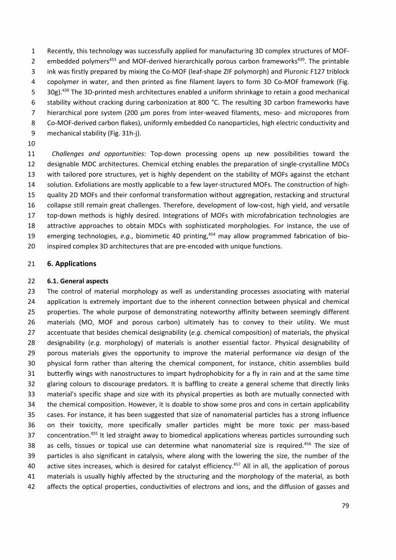
79
Recently, this technology was successfully applied for manufacturing 3D complex structures of MOF-1 embedded polymers453 and MOF-derived hierarchically porous carbon frameworks439. The printable 2 ink was firstly prepared by mixing the Co-MOF (leaf-shape ZIF polymorph) and Pluronic F127 triblock 3 copolymer in water, and then printed as fine filament layers to form 3D Co-MOF framework (Fig. 4 30g).439 The 3D-printed mesh architectures enabled a uniform shrinkage to retain a good mechanical 5 stability without cracking during carbonization at 800 °C. The resulting 3D carbon frameworks have 6 hierarchical pore system (200 μm pores from inter-weaved filaments, meso- and micropores from 7 Co-MOF-derived carbon flakes), uniformly embedded Co nanoparticles, high electric conductivity and 8 mechanical stability (Fig. 31h-j). 9
10 Challenges and opportunities: Top-down processing opens up new possibilities toward the 11
designable MDC architectures. Chemical etching enables the preparation of single-crystalline MDCs 12 with tailored pore structures, yet is highly dependent on the stability of MOFs against the etchant 13 solution. Exfoliations are mostly applicable to a few layer-structured MOFs. The construction of high-14 quality 2D MOFs and their conformal transformation without aggregation, restacking and structural 15 collapse still remain great challenges. Therefore, development of low-cost, high yield, and versatile 16 top-down methods is highly desired. Integrations of MOFs with microfabrication technologies are 17 attractive approaches to obtain MDCs with sophisticated morphologies. For instance, the use of 18 emerging technologies, e.g., biomimetic 4D printing,454 may allow programmed fabrication of bio-19 inspired complex 3D architectures that are pre-encoded with unique functions. 20
6. Applications 21
6.1. General aspects 22 The control of material morphology as well as understanding processes associating with material 23 application is extremely important due to the inherent connection between physical and chemical 24 properties. The whole purpose of demonstrating noteworthy affinity between seemingly different 25 materials (MO, MOF and porous carbon) ultimately has to convey to their utility. We must 26 accentuate that besides chemical designability (e.g. chemical composition) of materials, the physical 27 designability (e.g. morphology) of materials is another essential factor. Physical designability of 28 porous materials gives the opportunity to improve the material performance via design of the 29 physical form rather than altering the chemical component, for instance, chitin assemblies build 30 butterfly wings with nanostructures to impart hydrophobicity for a fly in rain and at the same time 31 glaring colours to discourage predators. It is baffling to create a general scheme that directly links 32 material's specific shape and size with its physical properties as both are mutually connected with 33 the chemical composition. However, it is doable to show some pros and cons in certain applicability 34 cases. For instance, it has been suggested that size of nanomaterial particles has a strong influence 35 on their toxicity, more specifically smaller particles might be more toxic per mass-based 36 concentration.455 It led straight away to biomedical applications whereas particles surrounding such 37 as cells, tissues or topical use can determine what nanomaterial size is required.456 The size of 38 particles is also significant in catalysis, where along with the lowering the size, the number of the 39 active sites increases, which is desired for catalyst efficiency.457 All in all, the application of porous 40 materials is usually highly affected by the structuring and the morphology of the material, as both 41 affects the optical properties, conductivities of electrons and ions, and the diffusion of gasses and 42
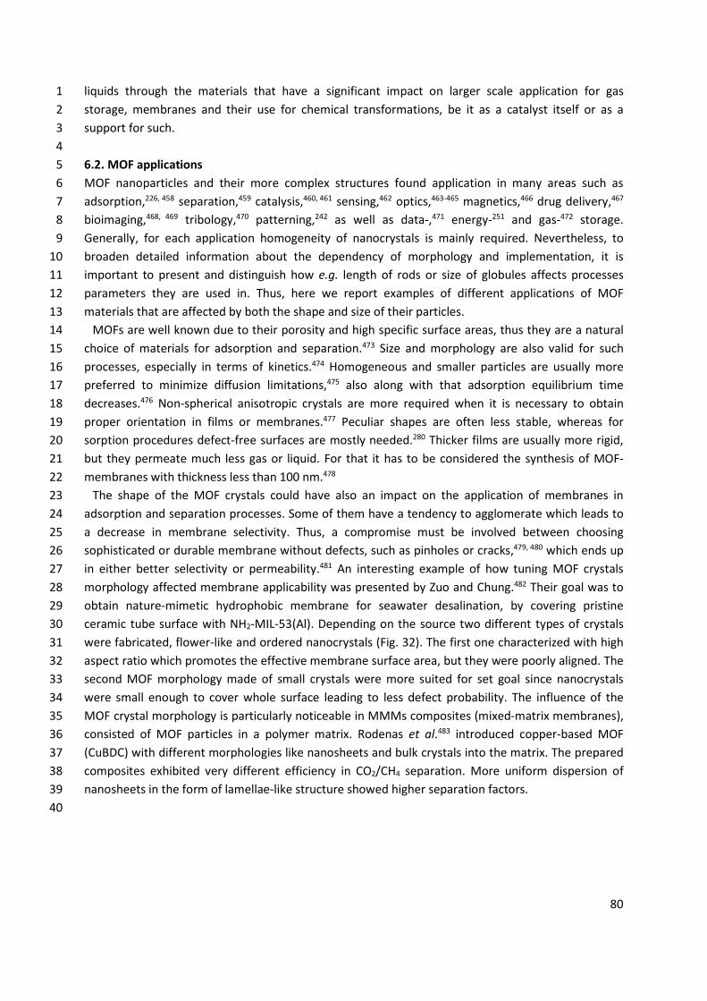
80
liquids through the materials that have a significant impact on larger scale application for gas 1 storage, membranes and their use for chemical transformations, be it as a catalyst itself or as a 2 support for such. 3 4 6.2. MOF applications 5 MOF nanoparticles and their more complex structures found application in many areas such as 6 adsorption,226, 458 separation,459 catalysis,460, 461 sensing,462 optics,463-465 magnetics,466 drug delivery,467 7 bioimaging,468, 469 tribology,470 patterning,242 as well as data-,471 energy-251 and gas-472 storage. 8 Generally, for each application homogeneity of nanocrystals is mainly required. Nevertheless, to 9 broaden detailed information about the dependency of morphology and implementation, it is 10 important to present and distinguish how e.g. length of rods or size of globules affects processes 11 parameters they are used in. Thus, here we report examples of different applications of MOF 12 materials that are affected by both the shape and size of their particles. 13
MOFs are well known due to their porosity and high specific surface areas, thus they are a natural 14 choice of materials for adsorption and separation.473 Size and morphology are also valid for such 15 processes, especially in terms of kinetics.474 Homogeneous and smaller particles are usually more 16 preferred to minimize diffusion limitations,475 also along with that adsorption equilibrium time 17 decreases.476 Non-spherical anisotropic crystals are more required when it is necessary to obtain 18 proper orientation in films or membranes.477 Peculiar shapes are often less stable, whereas for 19 sorption procedures defect-free surfaces are mostly needed.280 Thicker films are usually more rigid, 20 but they permeate much less gas or liquid. For that it has to be considered the synthesis of MOF-21 membranes with thickness less than 100 nm.478 22
The shape of the MOF crystals could have also an impact on the application of membranes in 23 adsorption and separation processes. Some of them have a tendency to agglomerate which leads to 24 a decrease in membrane selectivity. Thus, a compromise must be involved between choosing 25 sophisticated or durable membrane without defects, such as pinholes or cracks,479, 480 which ends up 26 in either better selectivity or permeability.481 An interesting example of how tuning MOF crystals 27 morphology affected membrane applicability was presented by Zuo and Chung.482 Their goal was to 28 obtain nature-mimetic hydrophobic membrane for seawater desalination, by covering pristine 29 ceramic tube surface with NH2-MIL-53(Al). Depending on the source two different types of crystals 30 were fabricated, flower-like and ordered nanocrystals (Fig. 32). The first one characterized with high 31 aspect ratio which promotes the effective membrane surface area, but they were poorly aligned. The 32 second MOF morphology made of small crystals were more suited for set goal since nanocrystals 33 were small enough to cover whole surface leading to less defect probability. The influence of the 34 MOF crystal morphology is particularly noticeable in MMMs composites (mixed-matrix membranes), 35 consisted of MOF particles in a polymer matrix. Rodenas et al.483 introduced copper-based MOF 36 (CuBDC) with different morphologies like nanosheets and bulk crystals into the matrix. The prepared 37 composites exhibited very different efficiency in CO2/CH4 separation. More uniform dispersion of 38 nanosheets in the form of lamellae-like structure showed higher separation factors. 39
40
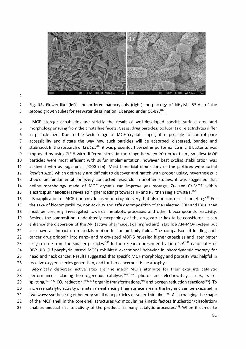
81
1
Fig. 32. Flower-like (left) and ordered nanocrystals (right) morphology of NH2-MIL-53(Al) of the 2 second growth tubes for seawater desalination (Licensed under CC-BY.482). 3
MOF storage capabilities are strictly the result of well-developed specific surface area and 4 morphology ensuing from the crystalline facets. Gases, drug particles, pollutants or electrolytes differ 5 in particle size. Due to the wide range of MOF crystal shapes, it is possible to control pore 6 accessibility and dictate the way how such particles will be adsorbed, dispersed, bonded and 7 stabilized. In the research of Li et al.484 it was presented how sulfur performance in Li-S batteries was 8 improved by using ZIF-8 with different sizes. In the range between 20 nm to 1 μm, smallest MOF 9 particles were most efficient with sulfur implementation, however best cycling stabilization was 10 achieved with average ones (~200 nm). Most beneficial dimensions of the particles were called 11 ‘golden size’, which definitely are difficult to discover and match with proper utility, nevertheless it 12 should be fundamental for every conducted research. In another studies, it was suggested that 13 define morphology made of MOF crystals can improve gas storage. Zr- and Cr-MOF within 14 electrospun nanofibers revealed higher loadings towards H2 and N2, than single crystals.485 15
Bioapplication of MOF is mainly focused on drug delivery, but also on cancer cell targeting.486 For 16 the sake of biocompatibility, non-toxicity and safe decomposition of the selected OBIs and IBUs, they 17 must be precisely investigated towards metabolic processes and other biocompounds reactivity. 18 Besides the composition, undoubtedly morphology of the drug carrier has to be considered. It can 19 enhance the dispersion of the API (active pharmaceutical ingredient), stabilize API-MOF system but 20 also have an impact on materials motion in human body fluids. The comparison of loading anti-21 cancer drug oridonin into nano- and micro-sized MOF-5 revealed higher capacities and later better 22 drug release from the smaller particles.487 In the research presented by Lin et al.488 nanoplates of 23 DBP-UiO (Hf-porphyrin based MOF) exhibited exceptional behavior in photodynamic therapy for 24 head and neck cancer. Results suggested that specific MOF morphology and porosity was helpful in 25 reactive oxygen species generation, and further cancerous tissue atrophy. 26
Atomically dispersed active sites are the major MOFs attribute for their exquisite catalytic 27 performance including heterogeneous catalysis,489, 490 photo- and electrocatalysis (i.e., water 28 splitting,491, 492 CO2 reduction,493, 494 organic transformations,495 and oxygen reduction reactions496). To 29 increase catalytic activity of materials enhancing their surface area is the key and can be executed in 30 two ways: synthesizing either very small nanoparticles or super-thin films.497 Also changing the shape 31 of the MOF shell in the core-shell structures via modulating kinetic factors (nucleation/dissolution) 32 enables unusual size selectivity of the products in many catalytic processes.498 When it comes to 33
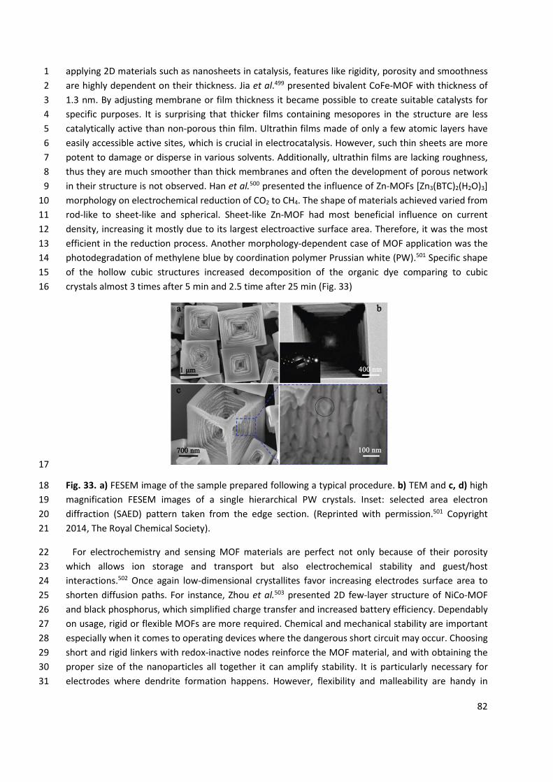
82
applying 2D materials such as nanosheets in catalysis, features like rigidity, porosity and smoothness 1 are highly dependent on their thickness. Jia et al.499 presented bivalent CoFe-MOF with thickness of 2 1.3 nm. By adjusting membrane or film thickness it became possible to create suitable catalysts for 3 specific purposes. It is surprising that thicker films containing mesopores in the structure are less 4 catalytically active than non-porous thin film. Ultrathin films made of only a few atomic layers have 5 easily accessible active sites, which is crucial in electrocatalysis. However, such thin sheets are more 6 potent to damage or disperse in various solvents. Additionally, ultrathin films are lacking roughness, 7 thus they are much smoother than thick membranes and often the development of porous network 8 in their structure is not observed. Han et al.500 presented the influence of Zn-MOFs [Zn3(BTC)2(H2O)3] 9 morphology on electrochemical reduction of CO2 to CH4. The shape of materials achieved varied from 10 rod-like to sheet-like and spherical. Sheet-like Zn-MOF had most beneficial influence on current 11 density, increasing it mostly due to its largest electroactive surface area. Therefore, it was the most 12 efficient in the reduction process. Another morphology-dependent case of MOF application was the 13 photodegradation of methylene blue by coordination polymer Prussian white (PW).501 Specific shape 14 of the hollow cubic structures increased decomposition of the organic dye comparing to cubic 15 crystals almost 3 times after 5 min and 2.5 time after 25 min (Fig. 33) 16
17
Fig. 33. a) FESEM image of the sample prepared following a typical procedure. b) TEM and c, d) high 18 magnification FESEM images of a single hierarchical PW crystals. Inset: selected area electron 19 diffraction (SAED) pattern taken from the edge section. (Reprinted with permission.501 Copyright 20 2014, The Royal Chemical Society). 21
For electrochemistry and sensing MOF materials are perfect not only because of their porosity 22 which allows ion storage and transport but also electrochemical stability and guest/host 23 interactions.502 Once again low-dimensional crystallites favor increasing electrodes surface area to 24 shorten diffusion paths. For instance, Zhou et al.503 presented 2D few-layer structure of NiCo-MOF 25 and black phosphorus, which simplified charge transfer and increased battery efficiency. Dependably 26 on usage, rigid or flexible MOFs are more required. Chemical and mechanical stability are important 27 especially when it comes to operating devices where the dangerous short circuit may occur. Choosing 28 short and rigid linkers with redox-inactive nodes reinforce the MOF material, and with obtaining the 29 proper size of the nanoparticles all together it can amplify stability. It is particularly necessary for 30 electrodes where dendrite formation happens. However, flexibility and malleability are handy in 31
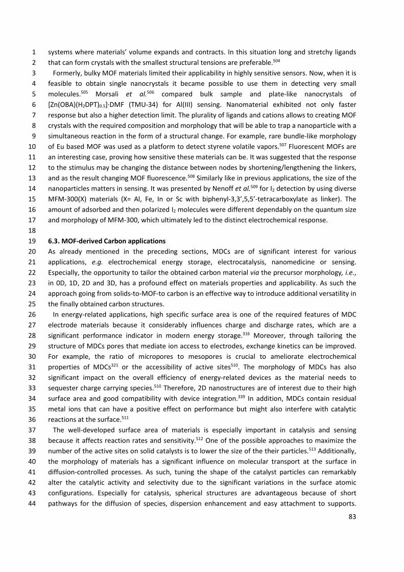
83
systems where materials’ volume expands and contracts. In this situation long and stretchy ligands 1 that can form crystals with the smallest structural tensions are preferable.504 2
Formerly, bulky MOF materials limited their applicability in highly sensitive sensors. Now, when it is 3 feasible to obtain single nanocrystals it became possible to use them in detecting very small 4 molecules.505 Morsali et al.506 compared bulk sample and plate-like nanocrystals of 5 [Zn(OBA)(H2DPT)0.5]·DMF (TMU-34) for Al(III) sensing. Nanomaterial exhibited not only faster 6 response but also a higher detection limit. The plurality of ligands and cations allows to creating MOF 7 crystals with the required composition and morphology that will be able to trap a nanoparticle with a 8 simultaneous reaction in the form of a structural change. For example, rare bundle-like morphology 9 of Eu based MOF was used as a platform to detect styrene volatile vapors.507 Fluorescent MOFs are 10 an interesting case, proving how sensitive these materials can be. It was suggested that the response 11 to the stimulus may be changing the distance between nodes by shortening/lengthening the linkers, 12 and as the result changing MOF fluorescence.508 Similarly like in previous applications, the size of the 13 nanoparticles matters in sensing. It was presented by Nenoff et al.509 for I2 detection by using diverse 14 MFM-300(X) materials (X= Al, Fe, In or Sc with biphenyl-3,3’,5,5’-tetracarboxylate as linker). The 15 amount of adsorbed and then polarized I2 molecules were different dependably on the quantum size 16 and morphology of MFM-300, which ultimately led to the distinct electrochemical response. 17 18 6.3. MOF-derived Carbon applications 19 As already mentioned in the preceding sections, MDCs are of significant interest for various 20 applications, e.g. electrochemical energy storage, electrocatalysis, nanomedicine or sensing. 21 Especially, the opportunity to tailor the obtained carbon material via the precursor morphology, i.e., 22 in 0D, 1D, 2D and 3D, has a profound effect on materials properties and applicability. As such the 23 approach going from solids-to-MOF-to carbon is an effective way to introduce additional versatility in 24 the finally obtained carbon structures. 25
In energy-related applications, high specific surface area is one of the required features of MDC 26 electrode materials because it considerably influences charge and discharge rates, which are a 27 significant performance indicator in modern energy storage.316 Moreover, through tailoring the 28 structure of MDCs pores that mediate ion access to electrodes, exchange kinetics can be improved. 29 For example, the ratio of micropores to mesopores is crucial to ameliorate electrochemical 30 properties of MDCs321 or the accessibility of active sites510. The morphology of MDCs has also 31 significant impact on the overall efficiency of energy-related devices as the material needs to 32 sequester charge carrying species.510 Therefore, 2D nanostructures are of interest due to their high 33 surface area and good compatibility with device integration.339 In addition, MDCs contain residual 34 metal ions that can have a positive effect on performance but might also interfere with catalytic 35 reactions at the surface.511 36
The well-developed surface area of materials is especially important in catalysis and sensing 37 because it affects reaction rates and sensitivity.512 One of the possible approaches to maximize the 38 number of the active sites on solid catalysts is to lower the size of the their particles.513 Additionally, 39 the morphology of materials has a significant influence on molecular transport at the surface in 40 diffusion-controlled processes. As such, tuning the shape of the catalyst particles can remarkably 41 alter the catalytic activity and selectivity due to the significant variations in the surface atomic 42 configurations. Especially for catalysis, spherical structures are advantageous because of short 43 pathways for the diffusion of species, dispersion enhancement and easy attachment to supports. 44
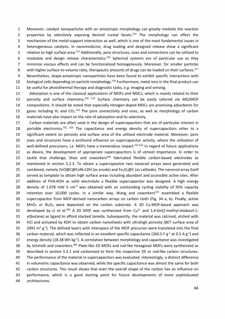
84
Moreover, catalyst nanoparticles with an anisotropic morphology can greatly mediate the reaction 1 properties by selectively exposing desired crystal facets.514 The morphology can affect the 2 mechanism of the metal-support interaction as well, which is one of the most fundamental issues in 3 heterogeneous catalysis. In nanomedicine, drug loading and designed release show a significant 4 relation to high surface area.515 Additionally, pore structures, sizes and connections can be utilized to 5 modulate and design release characteristics.516 Spherical systems are of particular use as they 6 minimize viscous effects and can be functionalized homogenously. Moreover, for smaller particles 7 with higher surface-to-volume ratio, therapeutic amounts of drugs can be loaded on their surfaces.517 8 Nevertheless, shape-anisotropic nanoparticles have been found to exhibit specific interactions with 9 biological cells depending on particle morphology.518 Furthermore, metal ions in the final product can 10 be useful for photothermal therapy and diagnostic tasks, e.g. imaging and sensing. 11
Adsorption is one of the classical applications of MOFs and MDCs, which is mainly related to their 12 porosity and surface chemistry.316, 519 Surface chemistry can be easily tailored via MO/MOF 13 compositions. It should be noted that especially nitrogen-doped MDCs are promising adsorbents for 14 gases including H2 and CO2.316 The pore connectivity and sizes, as well as morphology of carbon 15 materials have also impact on the rate of adsorption and its selectivity. 16
Carbon materials are often used in the design of supercapacitors that are of particular interest in 17 portable electronics.321, 520 The capacitance and energy density of supercapacitors relies to a 18 significant extent on porosity and surface area of the utilized electrode material. Moreover, pore 19 sizes and structures have a profound influence on supercapacitor activity, where the utilization of 20 well-defined precursors, i.e. MOFs have a tremendous impact.521-523 In regard of future applications 21 as device, the development of appropriate supercapacitors is of utmost importance. In order to 22 tackle that challenge, Shao and coworkers430 fabricated flexible carbon-based electrodes as 23 mentioned in section 5.2.3. To obtain a supercapacitor two nanorod arrays were generated and 24 combined, namely ZnO@C@CoNi-LDH (as anode) and Fe2O3@C (as cathode). The nanorod array itself 25 served as template to obtain high surface areas including abundant and accessible active sites. After 26 addition of PVA-KOH as solid electrolyte a flexible supercapacitor was designed. A high energy 27 density of 1.078 mW h cm-3 was obtained with an outstanding cycling stability of 95% capacity 28 retention over 10,000 cycles. In a similar way, Wang and coworkers524 assembled a flexible 29 supercapacitor from MOF-derived nanocarbon arrays on carbon cloth (Fig. 34 a, b). Finally, active 30 MnO2 or Bi2O3 were deposited on the carbon substrate. A 2D Cu-MOF-based approach was 31 developed by Li et al.209 A 2D MOF was synthesized from Cu2+ and 1,4-bis(2-methyl-imidazol-1-32 yl)butane) as ligand to afford stacked lamella. Subsequently, the material was calcined, etched with 33 HCl and activated by KOH to obtain carbon nanosheets with ultrahigh porosity (BET surface area of 34 2491 m2 g-1). The defined layers with interspace of the MOF precursor were translated into the final 35 carbon material, which was reflected in an excellent specific capacitance (260.5 F g-1 at 0.5 A g-1) and 36 energy density (18.38 Wh kg-1). A correlation between morphology and capacitance was investigated 37 by Schmidt and coworkers.360 Plate-like 2D MOFs and rod-like hexagonal MOFs were synthesized as 38 described in section 5.2.1 and carbonized to form the respective 2D or rod-like carbon structures. 39 The performance of the material in supercapacitors was evaluated. Interestingly, a distinct difference 40 in volumetric capacitance was observed, while the specific capacitance was almost the same for both 41 carbon structures. This result shows that even the overall shape of the carbon has an influence on 42 performance, which is a good starting point for future developments of more sophisticated 43 architectures. 44
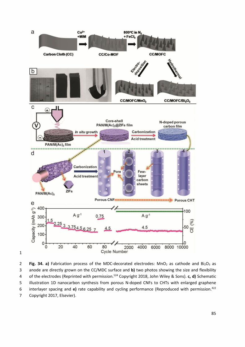
85
1
Fig. 34. a) Fabrication process of the MDC-decorated electrodes: MnO2 as cathode and Bi2O3 as 2 anode are directly grown on the CC/MDC surface and b) two photos showing the size and flexibility 3 of the electrodes (Reprinted with permission.524 Copyright 2018, John Wiley & Sons). c, d) Schematic 4 illustration 1D nanocarbon synthesis from porous N-doped CNFs to CHTs with enlarged graphene 5 interlayer spacing and e) rate capability and cycling performance (Reproduced with permission.422 6 Copyright 2017, Elsevier). 7
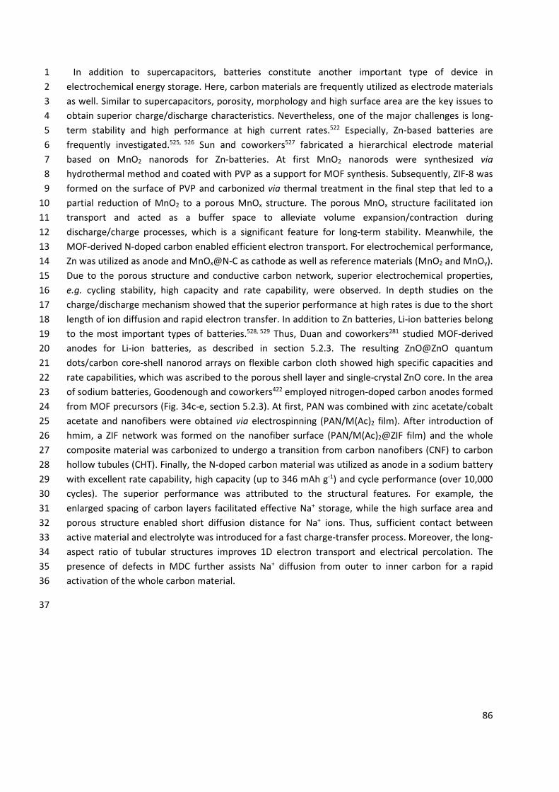
86
In addition to supercapacitors, batteries constitute another important type of device in 1 electrochemical energy storage. Here, carbon materials are frequently utilized as electrode materials 2 as well. Similar to supercapacitors, porosity, morphology and high surface area are the key issues to 3 obtain superior charge/discharge characteristics. Nevertheless, one of the major challenges is long-4 term stability and high performance at high current rates.522 Especially, Zn-based batteries are 5 frequently investigated.525, 526 Sun and coworkers527 fabricated a hierarchical electrode material 6 based on MnO2 nanorods for Zn-batteries. At first MnO2 nanorods were synthesized via 7 hydrothermal method and coated with PVP as a support for MOF synthesis. Subsequently, ZIF-8 was 8 formed on the surface of PVP and carbonized via thermal treatment in the final step that led to a 9 partial reduction of MnO2 to a porous MnOx structure. The porous MnOx structure facilitated ion 10 transport and acted as a buffer space to alleviate volume expansion/contraction during 11 discharge/charge processes, which is a significant feature for long-term stability. Meanwhile, the 12 MOF-derived N-doped carbon enabled efficient electron transport. For electrochemical performance, 13 Zn was utilized as anode and MnOx@N-C as cathode as well as reference materials (MnO2 and MnOy). 14 Due to the porous structure and conductive carbon network, superior electrochemical properties, 15 e.g. cycling stability, high capacity and rate capability, were observed. In depth studies on the 16 charge/discharge mechanism showed that the superior performance at high rates is due to the short 17 length of ion diffusion and rapid electron transfer. In addition to Zn batteries, Li-ion batteries belong 18 to the most important types of batteries.528, 529 Thus, Duan and coworkers281 studied MOF-derived 19 anodes for Li-ion batteries, as described in section 5.2.3. The resulting ZnO@ZnO quantum 20 dots/carbon core-shell nanorod arrays on flexible carbon cloth showed high specific capacities and 21 rate capabilities, which was ascribed to the porous shell layer and single-crystal ZnO core. In the area 22 of sodium batteries, Goodenough and coworkers422 employed nitrogen-doped carbon anodes formed 23 from MOF precursors (Fig. 34c-e, section 5.2.3). At first, PAN was combined with zinc acetate/cobalt 24 acetate and nanofibers were obtained via electrospinning (PAN/M(Ac)2 film). After introduction of 25 hmim, a ZIF network was formed on the nanofiber surface (PAN/M(Ac)2@ZIF film) and the whole 26 composite material was carbonized to undergo a transition from carbon nanofibers (CNF) to carbon 27 hollow tubules (CHT). Finally, the N-doped carbon material was utilized as anode in a sodium battery 28 with excellent rate capability, high capacity (up to 346 mAh g-1) and cycle performance (over 10,000 29 cycles). The superior performance was attributed to the structural features. For example, the 30 enlarged spacing of carbon layers facilitated effective Na+ storage, while the high surface area and 31 porous structure enabled short diffusion distance for Na+ ions. Thus, sufficient contact between 32 active material and electrolyte was introduced for a fast charge-transfer process. Moreover, the long-33 aspect ratio of tubular structures improves 1D electron transport and electrical percolation. The 34 presence of defects in MDC further assists Na+ diffusion from outer to inner carbon for a rapid 35 activation of the whole carbon material. 36
37
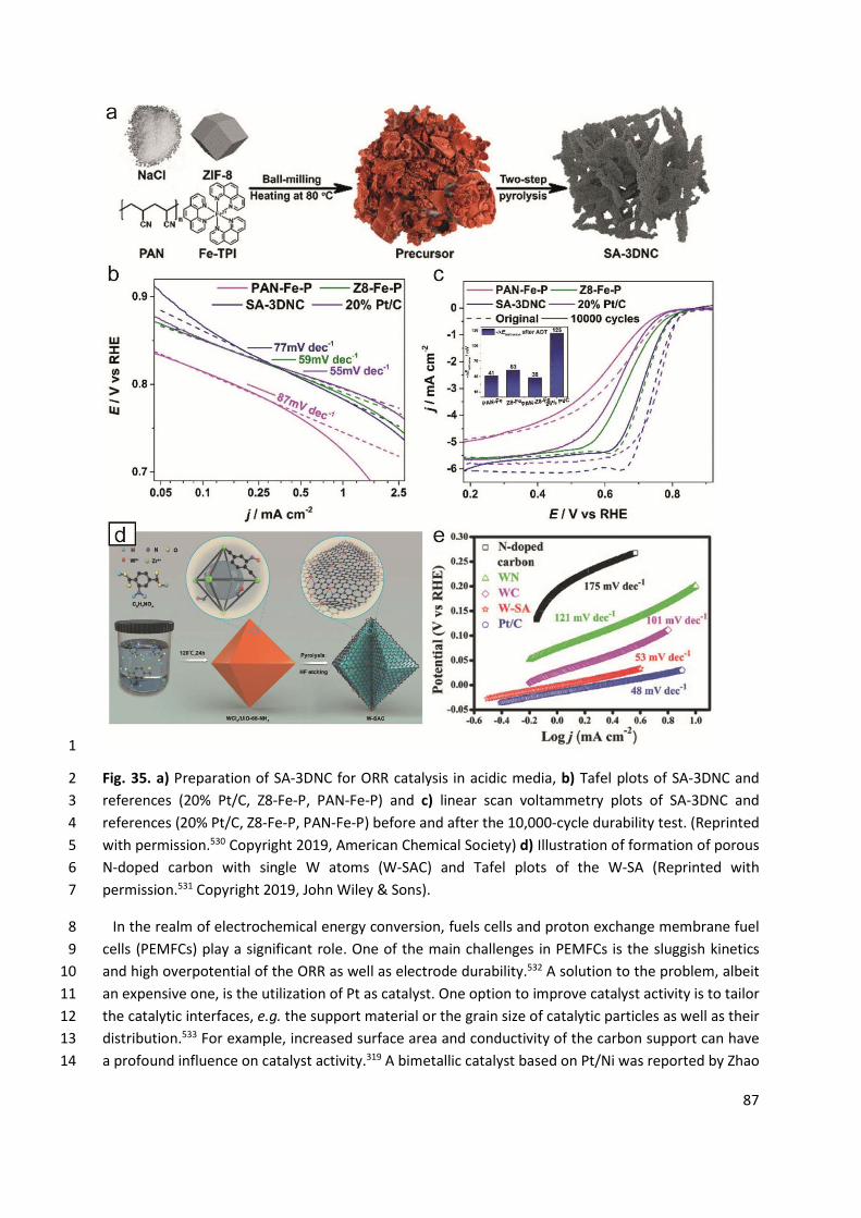
87
1
Fig. 35. a) Preparation of SA-3DNC for ORR catalysis in acidic media, b) Tafel plots of SA-3DNC and 2 references (20% Pt/C, Z8-Fe-P, PAN-Fe-P) and c) linear scan voltammetry plots of SA-3DNC and 3 references (20% Pt/C, Z8-Fe-P, PAN-Fe-P) before and after the 10,000-cycle durability test. (Reprinted 4 with permission.530 Copyright 2019, American Chemical Society) d) Illustration of formation of porous 5 N-doped carbon with single W atoms (W-SAC) and Tafel plots of the W-SA (Reprinted with 6 permission.531 Copyright 2019, John Wiley & Sons). 7
In the realm of electrochemical energy conversion, fuels cells and proton exchange membrane fuel 8 cells (PEMFCs) play a significant role. One of the main challenges in PEMFCs is the sluggish kinetics 9 and high overpotential of the ORR as well as electrode durability.532 A solution to the problem, albeit 10 an expensive one, is the utilization of Pt as catalyst. One option to improve catalyst activity is to tailor 11 the catalytic interfaces, e.g. the support material or the grain size of catalytic particles as well as their 12 distribution.533 For example, increased surface area and conductivity of the carbon support can have 13 a profound influence on catalyst activity.319 A bimetallic catalyst based on Pt/Ni was reported by Zhao 14
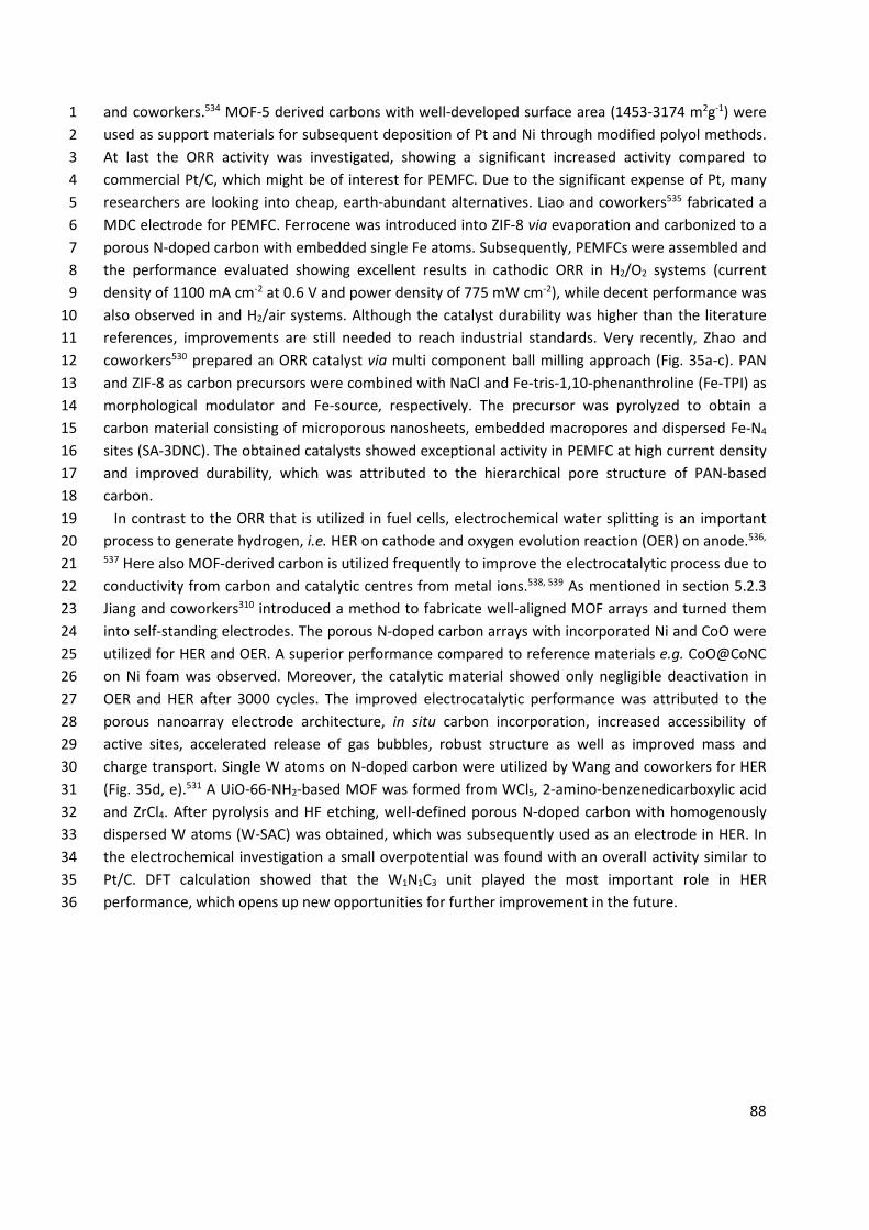
88
and coworkers.534 MOF-5 derived carbons with well-developed surface area (1453-3174 m2g-1) were 1 used as support materials for subsequent deposition of Pt and Ni through modified polyol methods. 2 At last the ORR activity was investigated, showing a significant increased activity compared to 3 commercial Pt/C, which might be of interest for PEMFC. Due to the significant expense of Pt, many 4 researchers are looking into cheap, earth-abundant alternatives. Liao and coworkers535 fabricated a 5 MDC electrode for PEMFC. Ferrocene was introduced into ZIF-8 via evaporation and carbonized to a 6 porous N-doped carbon with embedded single Fe atoms. Subsequently, PEMFCs were assembled and 7 the performance evaluated showing excellent results in cathodic ORR in H2/O2 systems (current 8 density of 1100 mA cm-2 at 0.6 V and power density of 775 mW cm-2), while decent performance was 9 also observed in and H2/air systems. Although the catalyst durability was higher than the literature 10 references, improvements are still needed to reach industrial standards. Very recently, Zhao and 11 coworkers530 prepared an ORR catalyst via multi component ball milling approach (Fig. 35a-c). PAN 12 and ZIF-8 as carbon precursors were combined with NaCl and Fe-tris-1,10-phenanthroline (Fe-TPI) as 13 morphological modulator and Fe-source, respectively. The precursor was pyrolyzed to obtain a 14 carbon material consisting of microporous nanosheets, embedded macropores and dispersed Fe-N4 15 sites (SA-3DNC). The obtained catalysts showed exceptional activity in PEMFC at high current density 16 and improved durability, which was attributed to the hierarchical pore structure of PAN-based 17 carbon. 18
In contrast to the ORR that is utilized in fuel cells, electrochemical water splitting is an important 19 process to generate hydrogen, i.e. HER on cathode and oxygen evolution reaction (OER) on anode.536, 20 537 Here also MOF-derived carbon is utilized frequently to improve the electrocatalytic process due to 21 conductivity from carbon and catalytic centres from metal ions.538, 539 As mentioned in section 5.2.3 22 Jiang and coworkers310 introduced a method to fabricate well-aligned MOF arrays and turned them 23 into self-standing electrodes. The porous N-doped carbon arrays with incorporated Ni and CoO were 24 utilized for HER and OER. A superior performance compared to reference materials e.g. CoO@CoNC 25 on Ni foam was observed. Moreover, the catalytic material showed only negligible deactivation in 26 OER and HER after 3000 cycles. The improved electrocatalytic performance was attributed to the 27 porous nanoarray electrode architecture, in situ carbon incorporation, increased accessibility of 28 active sites, accelerated release of gas bubbles, robust structure as well as improved mass and 29 charge transport. Single W atoms on N-doped carbon were utilized by Wang and coworkers for HER 30 (Fig. 35d, e).531 A UiO-66-NH2-based MOF was formed from WCl5, 2-amino-benzenedicarboxylic acid 31 and ZrCl4. After pyrolysis and HF etching, well-defined porous N-doped carbon with homogenously 32 dispersed W atoms (W-SAC) was obtained, which was subsequently used as an electrode in HER. In 33 the electrochemical investigation a small overpotential was found with an overall activity similar to 34 Pt/C. DFT calculation showed that the W1N1C3 unit played the most important role in HER 35 performance, which opens up new opportunities for further improvement in the future. 36
89
1
Fig. 36. a) Preparation of graphene encapsulated cobalt oxide- and cobalt-nanoparticles supported 2 on carbon by the pyrolysis of cobalt-terephthalic acid MOF-carbon template and b) the recycling of 3 cobalt-terephthalic acid MOF@C-800-catalyst for the hydrogenation of benzonitrile to benzylamine 4 (Reaction condition: 5 mmol benzonitrile, 250 mg catalyst, (3.8 mol% Co), 20 mL toluene, 25 bar H2, 5 5 bar NH3, 120 °C, 16 h) (Licensed under CC-BY540). c) Schematic formation of Fe, La and Zr-MOFs, 6 calcination to obtain MDC, formation of AChE-modified electrodes and their inhibition curves for 7 methyl parathion (Reproduced with permission.541 Copyright 2018, American Chemical Society). 8
MOFs are well-known for their catalytic activity,542-544 which also counts for MDCs. Jagadeesh and 9 coworkers540 used a Co-MOF as template to form an efficient carbon catalyst for hydrogenation of 10 benzonitrile (Fig. 36a,b). A Co-BDC MOF was pyrolyzed to obtain activated carbon catalyst with 11 embedded Co3O4- and Co-nanoparticles. The catalyst did not require nitrogen doping could be 12 utilized on a large gram scale and recycled in a versatile way. Qian and coworkers545 applied a Ni-13 based MOF to synthesize a carbon-based hydrogenation catalyst. A Ni-BTC MOF was pyrolyzed and 14 used for the reduction of 4-nitrophenol with a significant catalytic efficiency. Finally, the catalysts 15 could be recovered with a magnet, which allowed easy recycling. Zhao and coworkers546 combined 16 graphitic carbon nitride (g-CN) with ZIF-8 derived carbon for enhanced photocatalysis. At first ZIF-8 17 particles were carbonized and deposited on the g-CN 2D surface. Next, visible light induced 18 photocatalytic degradation of bisphenol A was studied. An improved catalytic activity was attributed 19 to the enhanced light harvesting and efficient interfacial charge separation between g-C3N4 and ZIF-20 8-derived carbon. Such a catalyst is of significant interest for waste water remediation as it can be 21 used to degrade small molecule pollutants, i.e. drug residues or residues from agriculture. 22
One of the common applications of MOFs is sensing.470, 547, 548 Both enzymatic and non-enzymatic 23 sensors are described in the literature. Moreover, carbon materials derived from MOFs are utilized in 24 sensing as well, which can be ascribed to several factors.549-551 On one hand, MDC presents a defined 25 environment for analytes that might be useful for the selectivity of the sensor. On the other hand, 26
90
the defined environment enables a precise deposition and implementation of the (bio)recognition 1 site, e.g. a reactive group or enzyme. Finally, the high surface area of MOFs and MDCs allows 2 increasing number and rate of interactions with the analyte, which leads to improved sensitivity. As 3 such, improved structural control has a profound influence on sensor performance, i.e. sensitivity 4 and selectivity, which also leads the direction for future improvements. Thus, the MDC approach 5 allows specific tailoring of the environment for the respective sensing application, e.g. with respect 6 to analyte concentration, presence of competing analytes and rate of analysis. Dong and 7 coworkers541 described MDC nanocomposites for enzyme immobilization (Fig. 36c). Fe3+, Zr4+ and La3+ 8 were combined with 2-aminoterephthalate to form three MOFs. After carbonization, 9 acetylcholinesterase was immobilized in the carbon/MOF structures to perform biosensing of methyl 10 parathion. The La3+-derived structures showed the best performance, which was deduced to their 11 hierarchical and highly porous architecture. As such, increased amounts of enzyme could be 12 immobilized, electron transfer enhanced and diffusion length of the analyte on the electrode surface 13 shortened. Therefore, biosensors with a linear detection range for concentrations from 1.0×10⁻¹³ to 14 5×10-19 g mL-1 and the lowest detection limit of 5.8×10⁻¹⁴ g mL-1 were fabricated. A non-enzymatic 15 glucose sensor was described by Fransaer and coworkers.552 HKUST-1 was grown on a Cu-foam 16 substrate and pyrolyzed to obtain carbon particles with embedded Cu nanoparticles on the Cu-17 substrate. The fabricated electrode showed high sensitivity, low detection limit and good stability for 18 the non-enzymatic detection of glucose. The superior performance was benefitted from the 19 hierarchical structure of the electrode, the synergistic effect of Cu and carbon as well as their close 20 contact. A molecularly imprinted sensor was presented by Ma and coworkers.553 On a glassy carbon 21 electrode, carbon nanotubes and MOF-5 derived carbon were deposited. After cleaning, pyrrole was 22 electropolymerized on the carbon surface in the presence of cysteine to obtain molecular imprinting 23 for the cysteine molecule. The sensors could be utilized for enantioselective detection of cysteine 24 enantiomers and then regenerated via an overoxidation process and pH adjustment. 25
Nanomedicine is another important area of applications for MOFs.554-556 Hence, MDCs found some 26 application in nanomedicine as well with particular areas as controlled drug delivery, bio-imaging and 27 photothermal therapy.515 The MDCs bring several features that are useful for nanomedicine. For 28 example, improved drug loading and delivery due to well-developed surface area, tunable pore size 29 and functionalizable surface. Metal incorporation enables therapeutic effects, e.g. photothermal 30 energy conversion. In addition, the combination with fluorescent material facilitates diagnostic tasks, 31 like imaging and sensing. MDCs provide promising supports to combine diagnostic and therapeutic 32 tasks in one system. Liu and coworkers557 described the sonodynamic therapy via MDC. ZIF-8 was 33 coated with mesoporous SiO2 to prevent aggregation, pyrolyzed and etched to obtain mesoporous 34 carbon nanoparticles. The key for sonodynamic therapy was the porphyrin-like metal centers formed 35 during the pyrolysis process. Next, the sonodynamic therapy was studied in vitro and in vivo. The 36 particles were introduced into tumor tissues via the enhanced permeability and retention effect. 37 Upon irradiation with ultrasound reactive oxygen species were generated, e.g. singlet O2 as well as 38 hydroxyl radicals that have the therapeutic effect to induce tumor cell apoptosis. Due to the high 39 surface area and pore structure a strong cavitation effect in combination with ultrasound was 40 observed that greatly enhanced the sonodynamic therapy efficiency. In the realm of drug delivery, 41 Yamauchi and coworkers558 studied ZIF-8 derived carbon nanoparticles as intracellular carriers. A 42 significant loading of cis-platin drug as well as a zero-order release profile in the first 20 h were 43 observed. The carbon nanoparticles exhibited excellent biocompatibility even at doses above 100 µg 44
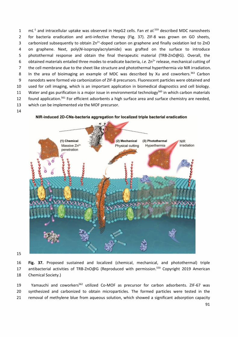
91
mL-1 and intracellular uptake was observed in HepG2 cells. Fan et al.559 described MDC nanosheets 1 for bacteria eradication and anti-infective therapy (Fig. 37). ZIF-8 was grown on GO sheets, 2 carbonized subsequently to obtain Zn2+-doped carbon on graphene and finally oxidation led to ZnO 3 on graphene. Next, poly(N-isopropylacrylamide) was grafted on the surface to introduce 4 photothermal response and obtain the final therapeutic material (TRB-ZnO@G). Overall, the 5 obtained materials entailed three modes to eradicate bacteria, i.e. Zn2+ release, mechanical cutting of 6 the cell membrane due to the sheet like structure and photothermal hyperthermia via NIR irradiation. 7 In the area of bioimaging an example of MDC was described by Xu and coworkers.363 Carbon 8 nanodots were formed via carbonization of ZIF-8 precursors. Fluorescent particles were obtained and 9 used for cell imaging, which is an important application in biomedical diagnostics and cell biology. 10 Water and gas purification is a major issue in environmental technology560 in which carbon materials 11 found application.561 For efficient adsorbents a high surface area and surface chemistry are needed, 12 which can be implemented via the MOF precursor. 13 14
15
Fig. 37. Proposed sustained and localized (chemical, mechanical, and photothermal) triple 16 antibacterial activities of TRB-ZnO@G (Reproduced with permission.559 Copyright 2019 American 17 Chemical Society.) 18
Yamauchi and coworkers562 utilized Co-MOF as precursor for carbon adsorbents. ZIF-67 was 19 synthesized and carbonized to obtain microparticles. The formed particles were tested in the 20 removal of methylene blue from aqueous solution, which showed a significant adsorption capacity 21
92
(up to 500 mg g-1) and an overall incorporation of 99.9% after 24 h. Moreover, the methylene blue 1 loaded particles could be separated from the water easily via magnetic field. The adsorption of CO2 2 was studied by Li and coworkers.563 MOF-5 was synthesized and combined with urea to form N-3 doped porous carbon materials. Efficient CO2 capture was observed (3.7 mmol g-1 at 0 °C and 1 atm), 4 which was ascribed to the high surface area and the introduced functional groups. The interaction of 5 CO2 and the carbon structure was studied via DFT, showing the interaction with pyridinic, pyrrolic 6 and amino functions that give rise to the high CO2 adsorption performance. 7
The carbon materials have useful properties that enable various applications. Moreover, these 8 properties can be enhanced via structuring and synthetic control.564 An approach starting from well-9 defined and tailorable materials like MOFs facilitates a broad variety of properties and applications, 10 even more so if the palette of morphologies is increased by MO-derived MOFs templating. Due to the 11 formidable structural control enabled that way, in-depth investigations of structure-property 12 relationships become viable. Overall, it is obvious that MOFs, MO-derived MOFs and MO/MOF 13 combinations are significant tools to fabricate tailor-made carbon materials for various applications. 14 Certainly, important developments in the field can be expected in the future. 15 16
7. Conclusion and perspectives 17
Structural and morphological control over multiple length scales is one of the most fascinating and 18 important goal of modern solid state and material chemistry. Chemists have learned how to control 19 chemical and structural features with atomic precision and thus the properties of a large variety of 20 porous materials. The chemical control over porous molecular structures of MOF materials has 21 reached a level of sophistication that allows for a wide spectrum of applications. Such porous 22 materials can be developed in the form of films, membranes, monoliths, submicron particles or 23 powders that offer many different physicochemical properties that are obtained by combining their 24 porous texture (accessibility, pore volume, specific surface area, surface area to volume ratio) with 25 the intrinsic characteristics of the matrix (mechanical properties, adsorption, chemical functionality, 26 etc.). Although these hybrid materials have unprecedented degree of structural and functional 27 tunability, which should lead to breakthroughs in many key technologies, they are so little considered 28 in industry so far. 29
In general, structuring porous materials (i.e. morphology control at different length scales) gives the 30 opportunity to improve the material performance via design of the physical form rather than altering 31 the chemical component. Besides the unique chemical designability of MOF materials at the 32 molecular and nano length scale we wish to foster a pronounced attention for the creation of 33 architectures at the mesoscopic/macroscopic scale by the development of innovate bottom-up 34 and/or top-down strategies in order to increase the physical designability of those materials. 35
This aspect was taken into consideration by using MO as a precursor for synthesizing MOF 36 structures, as they provide new opportunities for morphology control of MOF/MDC. Thereby, MOs 37 play multiple roles, including architecture directing agents (templates), cation reservoirs (metal ion 38 source), preferential reaction sites for heterogeneous nucleation, and functional components in the 39 final composite materials. As we have shown in this review the morphology control of MO materials 40 at various length scales is extremely high and sophisticated, an impressive plethora of symmetrical 41 and asymmetrical 0D, 1D, 2D, 3D, and hierarchical architectures can be precisely synthesized. In 42
93
addition, MOs can be easily integrated with various functional substrates and host materials, and 1 pre-installed on specific locations to make desired patterns. 2
Starting from morphology control of MO itself, the transformation of MO into MOF and finally MDC 3 enables unprecedented structures and morphologies. As the predefined structures and morphologies 4 of MOs can be transferred to MOFs and MOF derivatives, the MO-to-MOF conversion strategy will 5 enable the preparation of MOF/MDCs with a high level of morphological diversities. Of particular 6 advantage in this approach is the ability to fabricate complex morphologies with multiple levels of 7 structural hierarchies which may be otherwise difficult to achieve. 8
In turn, morphology controlled MDCs have shown great potential in a number of applications such 9 as supercapacitors, batteries, fuel cells, catalysis, sensing, nanomedicine and adsorption. In energy 10 related applications surface area is a major feature for MDC electrode materials as it significantly 11 influences charge and discharge rates - one of the major performance indicators in modern energy 12 storage. MDCs are of particular utility for tailored porosity and pore structures that mediate ion 13 access to electrodes and allow to improve exchange kinetics. The morphology of MDCs has a 14 significant influence on the overall efficiency of energy related devices especially when the volume of 15 the device is relevant. In catalysis and sensing, surface area is of particular importance for high 16 accessibility of the active centres of catalysts or sensors. Therefore, high reaction rates and sensitivity 17 can be introduced. Moreover, the material morphology has a remarkable impact on molecular 18 transport around the surface, which is a way to regulate diffusion-controlled processes. The pore 19 structure is of considerable interest for tailoring substrate specificity or sensor selectivity, e.g. to 20 allow pore access for specific molecules only. 21
In nanomedicine drug loading and designed release show a significant relation to the well-22 developed surface area and pore structure, allowing the design of release characteristics through 23 structural tailoring by means of functionalization. Furthermore, in the scaffold incorporated metal 24 ions can be utilized directly for photothermal therapy and enable application in diagnostic tasks, e.g. 25 imaging and sensing. The MDC systems are a promising approach for theranostics. The classical 26 application of adsorption is mainly related to surface area and surface chemistry of MDCs. This 27 feature can be easily tailored via MO/MOF compositions. With the specificity of adsorption being 28 closely related to surface chemistry and pore structures, respectively, MOF precursors allow the 29 transfer of designed adsorption processes. Regarding the relation of MO/MOF/MDC with the 30 aforementioned applications, a deep understanding of structure-property relationships is missing so 31 far, where future research will have a significant impact. Although considerable progress has been 32 made in this research field over the past decade, there are still many challenges and limitations that 33 need to be resolved in the future. 34
In-depth understanding of kinetical and thermodynamical aspects of MO-to-MOF conversion are 35 highly required for the preservation of the morphology of the parent material, with many competing 36 rates influencing the conversion kinetics and hence the transition mechanism (dissolution 37 crystallization vs template-assisted transition). In particular, the balance between the release rate of 38 metal ions from MO and the coordination rate of metal ions with ligands is critical for controlled 39 MOF deposition on MOs. The other reaction parameters (e.g., solvent composition, temperature and 40 pH) as well as the inherent nature of MOs (e.g., chemical composition, morphology, size, surface 41 roughness and surface charge) also greatly affect the MO-to-MOF conversion. As a result, only a few 42 MOs (e.g., ZnO, CoOx, CuOx) are widely utilized for fabrication of ‘typical’ MOFs so far, such as ZIF, 43 MIL and HKUST-1. A combination of theoretical calculations and experimental approaches is highly 44
94
desired to expand the range of possible MOs. High throughput methods would allow for rapid 1 screening of potential solid precursors and help to establish the suitable transformation conditions. 2
At the moment MO-to-MOF conversion strategy is still rather complicated and expensive 3 hampering large scale applications. Development of fast and economical conversion pathways would 4 be highly appreciated and a considerable driver for the development of the field. Direct conversion of 5 low-cost raw materials (e.g., earth-abundant bio-minerals, solids from large-scale industrial 6 production) into value-added MOF products will attract great attention, both in academia and 7 industry. 8
Higher level of control over morphology, size and composition of MOF/MDC is greatly desirable. A 9 considerable part of the literature relies on the use MO nanorod-array grown on 2D substrates to 10 form 3D architectures. Future research should focus on development of sophisticated 3D 11 architectures constructed by various building blocks (MO, MOFs, carbon, and substrates). For 12 instance, bio-inspired complex hierarchical architectures that are pre-encoded with unique functions 13 are of great interest. In addition, controllable design and integration of different kinds of 14 MO/MOF/MDC are essential to achieve collective and synergistic effect from the individual 15 components for target applications. However, in many cases, the parent MOs remain in the final 16 composite materials after transition to MOF or MDC, but barely contribute to performance 17 enhancement. They merely occupy the volume of the composites (devices), and this dead volume is a 18 significant problem in applications where volumetric performance is relevant, e.g. in portable 19 electronics. In this regard, precise material design is desired to merge the advantage of each 20 component into one hybrid material. 21
In addition, the relationships between MOF/MDC morphologies and their properties further need 22 to be established. Although a wide variety of MOF/MDC with different compositions and 23 morphologies are reported, there are no systematic investigation of the morphology-property 24 relationship. To study the effect of morphology on MOF/MDC properties, all the other factors, e.g. 25 crystallinity, particle size, porosity, surface area, configuration of carbon and heteroatom, doping 26 level, degree of graphitization and more, should remain constant. However, those factors are often 27 mutually interconnected with the morphology itself, so it is challenging to investigate the “true 28 morphology effect” exclusively. Thus, systematic and precise morphology control is highly required 29 to understand how MOF/MDC morphology really affects the materials properties in order to 30 optimize the application performance. 31
As highlighted in this review, morphology control (physical designability of materials) is an effective 32 and versatile way to control the intrinsic physical and chemical characteristics of materials without 33 changing their chemical compositions. Therefore, we believe that precise morphology control could 34 add a new dimension to the range of possible applications for MOF and MDC. As such, MO-to-MOF 35 and MOF-to-MDC conversion strategy will play a decisive role, because it enables direct access to 36 complex morphologies that are difficult to achieve otherwise. Although considerable advancements 37 have been achieved in recent years, this research field is still in its infancy, and there are still great 38 opportunities to be explored in the future. We expect that this review will provide a general 39 overview of the previous contribution, so that the future direction of morphology control can be 40 foreseen. Further research in the future is going to unravel new breakthroughs in the development 41 of MOF/MDC with defined structures and morphologies that are pre-designed for target applications 42 and device fabrications. 43
44
95
Conflicts of interest 1
There are no conflicts to declare. 2
3
Acknowledgements 4
Dr. Joanna Goscianska and Aleksander Ejsmont would like to thank the National Science Centre, 5 Poland (project SONATA-12 no: 2016/23/D/NZ7/01347) for financial support. 6
7
Abbreviations 8
3DOM 3D-ordered macroporous Ac acetate AChE acetylcholinesterase ADA 1,3-adamantanediacetic acid ALD atomic layer deposition AOT sodium bis(2-ethylhexyl)sulfosuccinate BDC 1,4-benzenedicarboxylate BET Brunauer-Emmett-Teller BTC 1,3,5-benzenetricarboxylate CC carbon cloth CCH cobalt carbonate hydroxide CHT carbon hollow tubules CNF carbon nanofibers CNT carbon nanotube CPE carbon paste electrode CVD chemical vapour deposition DABCO 1,4-diazabicyclo[2.2.2]octane DC dissolution-crystallization DFT density functional theory DMF dimethylformamide dopbdc 4,4′-dihydroxy-(1,1′-biphenyl)-3,3′-dicarboxylic acid DVB divinylbenzene ED electro deposition EDX energy-dispersive X-ray spectroscopy EPD electrophoretic deposition Fe-TPI Fe-tris-1,10-phenanthroline FTO fluorine doped tin oxide G graphene g-CN graphitic carbon nitride GO graphene oxide Hcaf caffeine
96
H-CoNC hollow Co and N co-doped carbon nanopolyhedra HER hydrogen evolution reaction HEtim 2-ethylimidazole HIPE high internal phase emulsion HKUST Hong Kong University of Science and Technology Hmim 2-methylimidazole IBU inorganic building unit IRMOF isoreticular MOF ITO indium doped tin oxide k kinetic rate KIT Korea Institute of Technology LAG liquid-assisted grinding LDH layered double-metal hydroxide MDC MOF-derived carbon MFF metal formate framework MIL Materials Institute Lavoisier MO metal oxide MOF metal-organic framework NC N-doped carbon NDC 2,6-naphthalene dicarboxylic acid NF Nickel foam NGC N-doped graphitic carbon NIR near infrared NRA nanorod arrays NTA nitrilotriacetic acid NW nanowires OBU organic building unit OER oxygen evolution reaction ORR oxygen reduction reaction PAA 1,4-phenylenediacetic acid PAN poly(acrylonitrile) PDA 1,3-propanediamine PEG poly(ethylene glycol) PEMFC proton exchange membrane fuel cell PIMs polymers of intrinsic microporosity PPF porphyrin paddlewheel framework PS poly(styrene) PVA poly(vinyl alcohol) PVP poly(N-vinylpyrrolidone) QD quantum dots
SA-3DNC three-dimensional carbon networks with atomically dispersed Fe−N4 active sites
SAM self-assembled monolayer SBA Santa Barbara Amorphous
97
SBU secondary building unit S-CoNCs solid Co and N-codoped carbon nanopolyhedra SDA structure directing agent SEM scanning electron microscopy SP shape-preservation SS-CNR spherical carbon nanorods superstructures STEM-EELS scanning transmission electron microscopy-electron energy loss spectroscopy SURMOF surface-mounted MOF TEM transmission electron microscopy TeNW tellurium nanowires TGA thermogravimetric analysis THF tetrahydrofuran TRB thermoresponsive brushes UiO Universitet i Oslo UNR CCH urchin-like nanorods of cobalt carbonate hydroxide UNT urchin-like nanotubes W-SAC N-doped carbon with homogenously dispersed W atoms XPS X-ray photoelectron spectroscopy ZIF zeolitic imidazolate framework 1
Reference 2
1. M. Peplow, Nature, 2015, 520, 148-150. 3 2. J. R. ILong and O. M. Yaghi, Chem. Soc. Rev., 2009, 38, 1213-1214. 4 3. H.-C. Zhou, J. R. Long and O. M. Yaghi, Chem. Rev., 2012, 112, 673-674. 5 4. H.-C. Zhou and S. Kitagawa, Chem. Soc. Rev., 2014, 43, 5415-5418. 6 5. G. Maurin, C. Serre, A. Cooper and G. Férey, Chem. Soc. Rev., 2017, 46, 3104-3107. 7 6. H. Furukawa, K. E. Cordova, M. O’Keeffe and O. M. Yaghi, Science, 2013, 341, 1230444. 8 7. A. G. Slater and A. I. Cooper, Science, 2015, 348, aaa8075. 9 8. R. Freund, U. Lächelt, T. Gruber, B. Rühle and S. Wuttke, ACS Nano, 2018, 12, 2094-2105. 10 9. Y. V. Kaneti, S. Dutta, M. S. A. Hossain, M. J. A. Shiddiky, K. L. Tung, F. K. Shieh, C. K. Tsung, K. 11
C. W. Wu and Y. Yamauchi, Adv. Mater., 2017, 29, 1700213. 12 10. S. Canossa, Z. Ji and S. Wuttke, Adv. Funct. Mater., 2019, DOI: 10.1002/adfm.201908547. 13 11. A. Azhar, Y. Li, Z. Cai, M. B. Zakaria, M. K. Masud, M. S. A. Hossain, J. Kim, W. Zhang, J. Na and 14
Y. Yamauchi, Bull. Chem. Soc. Jpn., 2019, 92, 875-904. 15 12. J. Tang, R. R. Salunkhe, H. Zhang, V. Malgras, T. Ahamad, S. M. Alshehri, N. Kobayashi, S. 16
Tominaka, Y. Ide and J. H. Kim, Sci. Rep., 2016, 6, 30295. 17 13. Y. V. Kaneti, J. Zhang, Y.-B. He, Z. Wang, S. Tanaka, M. S. A. Hossain, Z.-Z. Pan, B. Xiang, Q.-H. 18
Yang and Y. Yamauchi, J. Mater. Chem. A, 2017, 5, 15356-15366. 19 14. C. Wang, J. Kim, J. Tang, M. Kim, H. Lim, V. Malgras, J. You, Q. Xu, J. Li and Y. Yamauchi, Chem, 20
2019, DOI: 10.1016/j.chempr.2019.09.005. 21 15. A. D. McNaught and A. D. McNaught, Compendium of chemical terminology, Blackwell 22
Science Oxford, 1997. 23 16. M. Grzelczak, J. Pérez-Juste, P. Mulvaney and L. M. Liz-Marzán, Chem. Soc. Rev., 2008, 37, 24
1783-1791. 25 17. K. W. Powers, M. Palazuelos, B. M. Moudgil and S. M. Roberts, Nanotoxicology, 2007, 1, 42-26
51. 27
98
18. J. N. Tiwari, R. N. Tiwari and K. S. Kim, Prog. Mater. Sci., 2012, 57, 724-803. 1 19. H. Gleiter, Acta Mater., 2000, 48, 1-29. 2 20. V. Skorokhod, A. Ragulya and I. Uvarova, Kyiv: Academperidica, 2001. 3 21. V. V. Pokropivny and V. V. Skorokhod, Mater. Sci. Eng. C, 2007, 27, 990-993. 4 22. D. Nunes, A. Pimentel, L. Santos, P. Barquinha, L. Pereira, E. Fortunato and R. Martins, Metal 5
Oxide Nanostructures: Synthesis, Properties and Applications, Elsevier, 2018. 6 23. L. Qiao and M. T. Swihart, Adv. Colloid Interface Sci., 2017, 244, 199-266. 7 24. K. Pathakoti, H. M. Hwang, X. Wang and W. G. Aker, Int. J. Nanotechnol., 2013, 10, 1093-8
1108. 9 25. P. Li, C. Nan, Z. Wei, J. Lu, Q. Peng and Y. Li, Chem. Mater., 2010, 22, 4232-4236. 10 26. A. M. Kaczmarek and R. Van Deun, Chem. Soc. Rev., 2013, 42, 8835-8848. 11 27. S.-C. Lu, M.-C. Hsiao, M. Yorulmaz, L.-Y. Wang, P.-Y. Yang, S. Link, W.-S. Chang and H.-Y. Tuan, 12
Chem. Mater., 2015, 27, 8185-8188. 13 28. C. Zhu, X. Mu, P. A. van Aken, J. Maier and Y. Yu, Adv. Energy Mater., 2015, 5, 1401170. 14 29. J. Y. Baek, H.-W. Ha, I.-Y. Kim and S.-J. Hwang, J. Phys. Chem. C, 2009, 113, 17392-17398. 15 30. Y. Li, H. Tan, X. Y. Yang, B. Goris, J. Verbeeck, S. Bals, P. Colson, R. Cloots, G. Van Tendeloo 16
and B. L. Su, Small, 2011, 7, 475-483. 17 31. X. Zhang, P. Yu, D. Zhang, H. Zhang, X. Sun and Y. Ma, Mater. Lett., 2013, 92, 401-404. 18 32. C. J. Patridge, T.-L. Wu, C. Jaye, B. Ravel, E. S. Takeuchi, D. A. Fischer, G. Sambandamurthy 19
and S. Banerjee, Nano Lett., 2010, 10, 2448-2453. 20 33. Z. R. Tian, J. A. Voigt, J. Liu, B. McKenzie and H. Xu, J. Am. Chem. Soc., 2003, 125, 12384-21
12385. 22 34. W. Gao and Z. Li, Int. J. Nanotechnol., 2009, 6, 245-257. 23 35. J. H. Jung, H. Kobayashi, K. J. C. Van Bommel, S. Shinkai and T. Shimizu, Chem. Mater., 2002, 24
14, 1445-1447. 25 36. X. W. Lou, D. Deng, J. Y. Lee, J. Feng and L. A. Archer, Adv. Mater., 2008, 20, 258-262. 26 37. S. Kobayashi, K. Hanabusa, N. Hamasaki, M. Kimura, H. Shirai and S. Shinkai, Chem. Mater., 27
2000, 12, 1523-1525. 28 38. F. K. Butt, C. Cao, W. S. Khan, M. Safdar, X. Fu, M. Tahir, F. Idrees, Z. Ali, G. Nabi and D. Yu, 29
CrystEngComm, 2013, 15, 2106-2112. 30 39. G. Suo and J. Li, J. Alloys Compd., 2016, 674, 16-20. 31 40. Y. Xia, P. Yang, Y. Sun, Y. Wu, B. Mayers, B. Gates, Y. Yin, F. Kim and H. Yan, Adv. Mater., 32
2003, 15, 353-389. 33 41. X.-Y. Yang, L.-H. Chen, Y. Li, J. C. Rooke, C. Sanchez and B.-L. Su, Chem. Soc. Rev., 2017, 46, 34
481-558. 35 42. X. Liu, T. Ma, N. Pinna and J. Zhang, Adv. Funct. Mater., 2017, 27, 1702168. 36 43. B. Viswanath, P. Kundu, B. Mukherjee and N. Ravishankar, Nanotechnology, 2008, 19, 37
195603. 38 44. Z. Jing and J. Zhan, Adv. Mater., 2008, 20, 4547-4551. 39 45. X. Liu, W. Si, J. Zhang, X. Sun, J. Deng, S. Baunack, S. Oswald, L. Liu, C. Yan and O. G. Schmidt, 40
Sci. Rep., 2014, 4, 7452. 41 46. X. Lu, J. Deng, W. Si, X. Sun, X. Liu, B. Liu, L. Liu, S. Oswald, S. Baunack and H. J. Grafe, Adv. 42
Sci., 2015, 2, 1500113. 43 47. C. Chen, H. Jian, K. Mai, Z. Ren, J. Wang, X. Fu, C. Fan, C. Sun, G. Qian and Z. Wang, Eur. J. 44
Inorg. Chem., 2014, 2014, 3023-3029. 45 48. T. Yu, X. Cheng, X. Zhang, L. Sui, Y. Xu, S. Gao, H. Zhao and L. Huo, J. Mater. Chem. A, 2015, 3, 46
11991-11999. 47 49. N. K. Hassan and M. R. Hashim, J. Alloys Compd., 2013, 577, 491-497. 48 50. Y. F. Yuan, X. H. Xia, J. B. Wu, J. L. Yang, Y. B. Chen and S. Y. Guo, Electrochem. Commun., 49
2010, 12, 890-893. 50
99
51. Z. L. Wang, Adv. Mater., 2003, 15, 432-436. 1 52. Y. Peng, A.-W. Xu, B. Deng, M. Antonietti and H. Cölfen, J. Phys. Chem. B, 2006, 110, 2988-2
2993. 3 53. J. Mei, T. Liao, G. A. Ayoko, J. Bell and Z. Sun, Prog. Mater. Sci., 2019. 4 54. P. N. Vakil, D. A. Hardy and G. F. Strouse, ACS Nano, 2018, 12, 6784-6793. 5 55. H. Liu, W. Miao, S. Yang, Z. Zhang and J. Chen, Crystal Growth&Design, 2009, 9, 1733-1740. 6 56. Y. Zhang, J. Xu, Q. Xiang, H. Li, Q. Pan and P. Xu, J. Phys. Chem. C, 2009, 113, 3430-3435. 7 57. J. Liang, J. Liu, Q. Xie, S. Bai, W. Yu and Y. Qian, J. Phys. Chem. B, 2005, 109, 9463-9467. 8 58. X. Ma, J. Liu, C. Liang, X. Gong and R. Che, J. Mater. Chem. A, 2014, 2, 12692-12696. 9 59. G. Sun, B. Dong, M. Cao, B. Wei and C. Hu, Chem. Mater., 2011, 23, 1587-1593. 10 60. C. O'Dwyer, D. Navas, V. Lavayen, E. Benavente, M. A. Santa Ana, G. Gonzalez, S. B. Newcomb 11
and C. M. Sotomayor Torres, Chem. Mater., 2006, 18, 3016-3022. 12 61. S. Ghosh, P. Kar, N. Bhandary, S. Basu, S. Sardar, T. Maiyalagan, D. Majumdar, S. K. 13
Bhattacharya, A. Bhaumik and P. Lemmens, Catal. Sci. Technol., 2016, 6, 1417-1429. 14 62. S. Park, S. Lee, S. W. Seo, S.-D. Seo, C. W. Lee, D. Kim, D.-W. Kim and K. S. Hong, 15
CrystEngComm, 2013, 15, 2939-2948. 16 63. G. Brinkmann and N. Van Cleemput, Discrete Appl. Math., 2011, 159, 1528-1539. 17 64. M. Fang, G. Dong, R. Wei and J. C. Ho, Adv. Energy Mater., 2017, 7, 1700559. 18 65. M. R. Alenezi, S. J. Henley, N. G. Emerson and S. R. P. Silva, Nanoscale, 2014, 6, 235-247. 19 66. B. I. Kharisov, Recent Pat. Nanotech., 2008, 2, 190-200. 20 67. P. Madhusudan, Y. Wang, B. N. Chandrashekar, W. Wang, J. Wang, J. Miao, R. Shi, Y. Liang, G. 21
Mi and C. Cheng, Appl. Catal. B: Environ., 2019, 253, 379-390. 22 68. X. Song, C. Huang, Y. Qin, H. Li and H. C. Chen, J. Mater. Chem. A, 2018, 6, 16205-16212. 23 69. J. C. Védrine, ChemSusChem, 2019, 12, 577-588. 24 70. Q. Zhang, H.-Y. Wang, X. Jia, B. Liu and Y. Yang, Nanoscale, 2013, 5, 7175-7183. 25 71. Y. Li and W. Shen, Chem. Soc. Rev., 2014, 43, 1543-1574. 26 72. Y. Zhou, Y. Li and W. Shen, Chem. Asian J., 2016, 11, 1470-1488. 27 73. Y. Qu and X. Duan, Chem. Soc. Rev., 2013, 42, 2568-2580. 28 74. X. Mou, X. Wei, Y. Li and W. Shen, CrystEngComm, 2012, 14, 5107-5120. 29 75. I. Lee, F. Delbecq, R. Morales, M. A. Albiter and F. Zaera, Nat. Mater., 2009, 8, 132. 30 76. Z. Li, H. Li, Z. Wu, M. Wang, J. Luo, H. Torun, P. Hu, C. Yang, M. Grundmann and X. Liu, Mater. 31
Horiz., 2019, 6, 470-506. 32 77. B. Zhang and P.-X. Gao, Front. Mater., 2019, 6, 55. 33 78. Y.-F. Sun, S.-B. Liu, F.-L. Meng, J.-Y. Liu, Z. Jin, L.-T. Kong and J.-H. Liu, Sensors, 2012, 12, 2610-34
2631. 35 79. E. Comini and G. Sberveglieri, Mater. Today, 2010, 13, 36-44. 36 80. A. Kubacka, M. Fernandez-Garcia and G. Colon, Chem. Rev., 2011, 112, 1555-1614. 37 81. M. Adachi, Y. Murata, J. Takao, J. Jiu, M. Sakamoto and F. Wang, J. Am. Chem. Soc., 2004, 38
126, 14943-14949. 39 82. D. Sengupta, P. Das, B. Mondal and K. Mukherjee, Renew. Sustain. Energy Rev., 2016, 60, 40
356-376. 41 83. M. Dürr, S. Rosselli, A. Yasuda and G. Nelles, J. Phys. Chem. B, 2006, 110, 21899-21902. 42 84. K. Sivula, F. Le Formal and M. Grätzel, ChemSusChem, 2011, 4, 432-449. 43 85. M. Nagpal and R. Kakkar, Sep. Purif. Technol., 2019, 211, 522-539. 44 86. R. Bhateria and R. Singh, J. Water Process Eng., 2019, 31, 100845. 45 87. R. Gusain, K. Gupta, P. Joshi and O. P. Khatri, Adv. Colloid Interface Sci., 2019, 102009. 46 88. M. A. Islam, D. W. Morton, B. B. Johnson, B. Mainali and M. J. Angove, J. Water Process Eng., 47
2018, 26, 264-280. 48 89. M. Martínez-Carmona, Y. Gun’ko and M. Vallet-Regí, Nanomaterials, 2018, 8, 268. 49 90. Z. Assadi, G. Emtiazi and A. Zarrabi, J. Mol. Liq., 2018, 250, 375-380. 50
100
91. X. Huang, X. Zheng, Z. Xu and C. Yi, Int. J. Pharm., 2017, 534, 190-194. 1 92. A. K. Kodoth, V. M. Ghate, S. A. Lewis and V. Badalamoole, Int. J. Biol. Macromol., 2018, 115, 2
418-430. 3 93. P.-J. Lu, S.-C. Huang, Y.-P. Chen, L.-C. Chiueh and D. Y.-C. Shih, J. Food Drug Anal., 2015, 23, 4
587-594. 5 94. C.-L. Kuo, C.-L. Wang, H.-H. Ko, W.-S. Hwang, K.-m. Chang, W.-L. Li, H.-H. Huang, Y.-H. Chang 6
and M.-C. Wang, Ceram. Int., 2010, 36, 693-698. 7 95. M. J. Osmond and M. J. McCall, Nanotoxicology, 2010, 4, 15-41. 8 96. S. Yabe and T. Sato, J. Solid State Chem., 2003, 171, 7-11. 9 97. T.-D. Nguyen, Nanoscale, 2013, 5, 9455-9482. 10 98. C. Burda, X. Chen, R. Narayanan and M. A. El-Sayed, Chem. Rev., 2005, 105, 1025-1102. 11 99. J.-P. Jolivet, S. Cassaignon, C. Chanéac, D. Chiche, O. Durupthy and D. Portehault, C. R. 12
Chimie, 2010, 13, 40-51. 13 100. T.-D. Nguyen and T.-O. Do, Nanocrystal, 2011, 2, 55-84. 14 101. H.-D. Yu, M. D. Regulacio, E. Ye and M.-Y. Han, Chem. Soc. Rev., 2013, 42, 6006-6018. 15 102. C. T. Dinh, T. D. Nguyen, F. Kleitz and T. O. Do, Controlled Nanofabrication: Advances and 16
Applications, CRC Press, 2012. 17 103. J. Park, J. Joo, S. G. Kwon, Y. Jang and T. Hyeon, Angew. Chem., Int. Ed., 2007, 46, 4630-4660. 18 104. S. K. Tripathi, R. Kaur and M. Rani, Solid State Phenomena, 222, 67-97. 19 105. Y. w. Jun, J. s. Choi and J. Cheon, Angew. Chem., Int. Ed., 2006, 45, 3414-3439. 20 106. A. V. Nikam, B. L. V. Prasad and A. A. Kulkarni, CrystEngComm, 2018, 20, 5091-5107. 21 107. T. Guo, M.-S. Yao, Y.-H. Lin and C.-W. Nan, CrystEngComm, 2015, 17, 3551-3585. 22 108. C. J. Brinker and G. W. Scherer, Sol-gel science: the physics and chemistry of sol-gel 23
processing, Academic press, 2013. 24 109. S. Thiagarajan, A. Sanmugam and D. Vikraman, Recent Applications in Sol-Gel Synthesis, 2017, 25
1-17. 26 110. W. Z. Wang, G. H. Wang, X. S. Wang, Y. J. Zhan, Y. K. Liu and C. L. Zheng, Adv. Mater., 2002, 27
14, 67-69. 28 111. C. H. Kuo, C. H. Chen and M. H. Huang, Adv. Funct. Mater., 2007, 17, 3773-3780. 29 112. M. Pang and H. C. Zeng, Langmuir, 2010, 26, 5963-5970. 30 113. S. Sun, F. Zhou, L. Wang, X. Song and Z. Yang, Crystal Growth & Design, 2009, 10, 541-547. 31 114. W.-C. Huang, L.-M. Lyu, Y.-C. Yang and M. H. Huang, J. Am. Chem. Soc., 2011, 134, 1261-1267. 32 115. Y. Qiao, Y. Yu, Y. Jin, Y.-B. Guan and C.-H. Chen, Electrochim. Acta, 2014, 132, 323-331. 33 116. S.-I. Kim, J.-S. Lee, H.-J. Ahn, H.-K. Song and J.-H. Jang, ACS Appl. Mater. Interfaces, 2013, 5, 34
1596-1603. 35 117. T. Kavitha and H. Yuvaraj, J. Mater. Chem., 2011, 21, 15686-15691. 36 118. H. Karami and A. Mohammadi, Int. J. Electrochem. Sci, 2015, 10, 7392-7408. 37 119. Y. S. Kang, S. Risbud, J. F. Rabolt and P. Stroeve, Chem. Mater., 1996, 8, 2209-2211. 38 120. R. Itteboina and T. K. Sau, Mater. Today: Proceedings, 2019, 9, 458-467. 39 121. T. Sugimoto, K. Okada and H. Itoh, J. Colloid Interface Sci., 1997, 193, 140-143. 40 122. T. Sugimoto and X. Zhou, J. Colloid and Interface Sci., 2002, 252, 347-353. 41 123. T. Sugimoto, X. Zhou and A. Muramatsu, J. Colloid Interface Sci., 2002, 252, 339-346. 42 124. T. Sugimoto, X. Zhou and A. Muramatsu, J. Colloid Interface Sci., 2003, 259, 53-61. 43 125. G. Gundiah, S. Mukhopadhyay, U. G. Tumkurkar, A. Govindaraj, U. Maitra and C. N. R. Rao, J. 44
Mater. Chem., 2003, 13, 2118-2122. 45 126. A. Biswas, A. Corani, A. Kathiravan, Y. Infahsaeng, A. Yartsev, V. Sundstrom and S. De, 46
Nanotechnology, 2013, 24, 195601. 47 127. A. R. Armstrong, G. Armstrong, J. Canales, R. García and P. G. Bruce, Adv. Mater., 2005, 17, 48
862-865. 49 128. A. Q. Pan, H. B. Wu, L. Zhang and X. W. D. Lou, Energy Environ. Sci., 2013, 6, 1476-1479. 50
101
129. G. Liu, Q. Deng, H. Wang, S. Kang, Y. Yang, D. H. L. Ng, W. Cai and G. Wang, Chem. Eur. J., 1 2012, 18, 13418-13426. 2
130. A. G. Roca, L. Gutiérrez, H. Gavilán, M. E. F. Brollo, S. Veintemillas-Verdaguer and M. del 3 Puerto Morales, Adv. Drug Deliv. Rev., 2018. 4
131. H. Wang, L. Zhang, X. Tan, C. M. B. Holt, B. Zahiri, B. C. Olsen and D. Mitlin, J. Phys. Chem. C, 5 2011, 115, 17599-17605. 6
132. A.-M. Cao, J.-S. Hu, H.-P. Liang, W.-G. Song, L.-J. Wan, X.-L. He, X.-G. Gao and S.-H. Xia, J. 7 Phys. Chem. B, 2006, 110, 15858-15863. 8
133. L. Zhuo, J. Ge, L. Cao and B. Tang, Crystal Growth & Design, 2008, 9, 1-6. 9 134. M. H. Kim, B. Lim, E. P. Lee and Y. Xia, J. Mater. Chem., 2008, 18, 4069-4073. 10 135. S. Shang, K. Xue, D. Chen and X. Jiao, CrystEngComm, 2011, 13, 5094-5099. 11 136. Y. Ren and L. Gao, J. Am. Ceram. Soc., 2010, 93, 3560-3564. 12 137. H. Zhang, D. Yang, X. Ma, Y. Ji, J. Xu and D. Que, Nanotechnology, 2004, 15, 622. 13 138. K. He, C.-Y. Xu, L. Zhen and W.-Z. Shao, Mater. Lett., 2007, 61, 3159-3162. 14 139. J. Wan, X. Chen, Z. Wang, X. Yang and Y. Qian, J. Cryst. Growth, 2005, 276, 571-576. 15 140. X. Li, Z. Si, Y. Lei, J. Tang, S. Wang, S. Su, S. Song, L. Zhao and H. Zhang, CrystEngComm, 2010, 16
12, 2060-2063. 17 141. C.-T. Dinh, T.-D. Nguyen, F. Kleitz and T.-O. Do, ACS Nano, 2009, 3, 3737-3743. 18 142. K. X. Yao, X. M. Yin, T. H. Wang and H. C. Zeng, J. Am. Chem. Soc., 2010, 132, 6131-6144. 19 143. Y. Li, M. Afzaal and P. O'Brien, J. Mater. Chem., 2006, 16, 2175-2180. 20 144. M. V. Kovalenko, M. I. Bodnarchuk, R. T. Lechner, G. Hesser, F. Schäffler and W. Heiss, J. Am. 21
Chem. Soc., 2007, 129, 6352-6353. 22 145. P. D. Cozzoli, M. L. Curri, A. Agostiano, G. Leo and M. Lomascolo, J. Phys. Chem. B, 2003, 107, 23
4756-4762. 24 146. T. Yu, J. Joo, Y. I. Park and T. Hyeon, J. Am. Chem. Soc., 2006, 128, 1786-1787. 25 147. Y. C. Cao, J. Am. Chem. Soc, 2004, 126, 7456-7457. 26 148. T. Hyeon, S. S. Lee, J. Park, Y. Chung and H. B. Na, J. Am. Chem. Soc., 2001, 123, 12798-12801. 27 149. J. Park, E. Kang, C. J. Bae, J.-G. Park, H.-J. Noh, J.-Y. Kim, J.-H. Park, H. M. Park and T. Hyeon, J. 28
Phy. Chem. B, 2004, 108, 13594-13598. 29 150. Y. Chen, E. Johnson and X. Peng, J. Am. Chem. Soc., 2007, 129, 10937-10947. 30 151. D. Zitoun, N. Pinna, N. Frolet and C. Belin, J. Am. Chem. SOc., 2005, 127, 15034-15035. 31 152. M. Salavati-Niasari, N. Mir and F. Davar, J. Phys. Chem. Solids, 2009, 70, 847-852. 32 153. J.-w. Seo, Y.-w. Jun, S. J. Ko and J. Cheon, J. Phy. Chem. B, 2005, 109, 5389-5391. 33 154. I. H. Lone, N. R. E. Radwan, J. Aslam and A. Akhter, Curr. Nanosci., 2019, 15, 129-136. 34 155. V. Uskoković and M. Drofenik, Surf. Rev. Lett., 2005, 12, 239-277. 35 156. M. Boutonnet, J. Kizling, P. Stenius and G. Maire, Coll. Surf., 1982, 5, 209-225. 36 157. A. Kumar, A. Saxena, A. De, R. Shankar and S. Mozumdar, Rsc Adv., 2013, 3, 5015-5021. 37 158. Y. Liu, C. Zheng, W. Wang, Y. Zhan and G. Wang, J. Cryst. Growth, 2001, 233, 8-12. 38 159. N. Pinna, M. Willinger, K. Weiss, J. Urban and R. Schlögl, Nano Lett., 2003, 3, 1131-1134. 39 160. F. Gu, Z. Wang, D. Han, C. Shi and G. Guo, Mater. Sci. Eng. B, 2007, 139, 62-68. 40 161. S. C. Kuiry, S. D. Patil, S. Deshpande and S. Seal, J. Phys. Chem. B, 2005, 109, 6936-6939. 41 162. X. Li, W. Zheng, G. He, R. Zhao and D. Liu, ACS Sustainable Chem. Eng., 2013, 2, 288-295. 42 163. A. Bumajdad and M. Madkour, Nanoscale Res. Lett., 2015, 10, 19. 43 164. B. Park, B. H. Kim and T. Yu, J. Colloid Interface Sci., 2018, 518, 27-33. 44 165. N. Zhao, W. Nie, X. Liu, S. Tian, Y. Zhang and X. Ji, Small, 2008, 4, 77-81. 45 166. N. Zhao, D. Pan, W. Nie and X. Ji, J. Am. Chem. Soc., 2006, 128, 10118-10124. 46 167. T.-D. Nguyen and T.-O. Do, J. Phy. Chem. C, 2009, 113, 11204-11214. 47 168. T.-D. Nguyen, D. Mrabet and T.-O. Do, J. Phy. Chem. C, 2008, 112, 15226-15235. 48 169. D. Pan, N. Zhao, Q. Wang, S. Jiang, X. Ji and L. An, Adv. Mater., 2005, 17, 1991-1995. 49
102
170. J. Zhang, S. Ohara, M. Umetsu, T. Naka, Y. Hatakeyama and T. Adschiri, Adv. Mater., 2007, 19, 1 203-206. 2
171. A. V. Rane, K. Kanny, V. K. Abitha and S. Thomas, in Synthesis of Inorganic Nanomaterials, 3 Elsevier, 2018, pp. 121-139. 4
172. X. Xia, Y. Zhang, D. Chao, C. Guan, Y. Zhang, L. Li, X. Ge, I. M. Bacho, J. Tu and H. J. Fan, 5 Nanoscale, 2014, 6, 5008-5048. 6
173. M. Farahmandjou and S. Jurablu, Int. J. Bio-Inorg. Hybr. Nanomater., 2014, 3, 179-184. 7 174. A. J. Ahamed and P. V. Kumar, J. Chem. Pharm. Res., 2016, 8, 624-628. 8 175. W. Wu, X. H. Xiao, F. Ren, S. F. Zhang and C. Z. Jiang, J. Low Temp. Phys., 2012, 168, 306-313. 9 176. S. Chen, J. Zhu, Q. Han, Z. Zheng, Y. Yang and X. Wang, Cryst. Growth & Des., 2009, 9, 4356-10
4361. 11 177. S. Tazikeh, A. Akbari, A. Talebi and E. Talebi, Mater. Sci.-Poland, 2014, 32, 98-101. 12 178. J. C. Park, J. Kim, H. Kwon and H. Song, Adv. Mater., 2009, 21, 803-807. 13 179. S. Stankic, S. Suman, F. Haque and J. Vidic, J. Nanobiotechnol., 2016, 14, 73. 14 180. W. Y. Teoh, R. Amal and L. Mädler, Nanoscale, 2010, 2, 1324-1347. 15 181. S. Grimm, M. Schultz, S. Barth and R. Muller, J. Mater. Sci., 1997, 32, 1083-1092. 16 182. S. Pokhrel, J. Birkenstock, M. Schowalter, A. Rosenauer and L. Mädler, Cryst. Growth & Des., 17
2009, 10, 632-639. 18 183. S. Sel, O. Duygulu, U. Kadiroglu and N. E. Machin, Appl. Surf. Sci., 2014, 318, 150-156. 19 184. M. J. Height, L. Mädler, S. E. Pratsinis and F. Krumeich, Chem. Mater., 2006, 18, 572-578. 20 185. M. J. Lawrence, A. Kolodziej and P. Rodriguez, Cur. Opin. Electrochem., 2018, 10, 7-15. 21 186. C. A. C. Sequeira, Organic & Medicinal Chem., 2018, 5, 555660. 22 187. D. Khudhair, A. Bhatti, Y. Li, H. A. Hamedani, H. Garmestani, P. Hodgson and S. Nahavandi, 23
Mater. Sci. Eng. C, 2016, 59, 1125-1142. 24 188. D. Ramimoghadam, S. Bagheri and S. B. A. Hamid, J. Magn. Magn. Mater., 2014, 368, 207-25
229. 26 189. Y. Lu and X. Zhou, Thin Solid Films, 2018, 660, 180-185. 27 190. Y.-R. Lu, T.-Z. Wu, C.-L. Chen, D.-H. Wei, J.-L. Chen, W.-C. Chou and C.-L. Dong, Nanoscale Res. 28
Lett., 2015, 10, 387. 29 191. J. Yang, Y. Lin, Y. Meng and Y. Liu, Ceram. Int., 2012, 38, 4555-4559. 30 192. S.-L. Chou, J.-Z. Wang, H.-K. Liu and S.-X. Dou, J. Power Sources, 2008, 182, 359-364. 31 193. J. Y. Xiang, X. L. Wang, X. H. Xia, L. Zhang, Y. Zhou, S. J. Shi and J. P. Tu, Electrochim. Acta, 32
2010, 55, 4921-4925. 33 194. N. Zikalala, K. Matshetshe, S. Parani and O. S. Oluwafemi, Nano-Structures & Nano-Objects, 34
2018, 16, 288-299. 35 195. H. Agarwal, S. V. Kumar and S. Rajeshkumar, Resource-Efficient Technol., 2017, 3, 406-413. 36 196. H. Zhou, T. Fan, J. Ding, D. Zhang and Q. Guo, Optics Express, 2012, 20, A340-A350. 37 197. A. K. Jha, K. Prasad and A. R. Kulkarni, Colloids Surf. B., 2009, 71, 226-229. 38 198. Y. Suzuki, S. D. Kelly, K. M. Kemner and J. F. Banfield, Nature, 2002, 419, 134. 39 199. K. Ali, S. Dwivedi, A. Azam, Q. Saquib, M. S. Al-Said, A. A. Alkhedhairy and J. Musarrat, J. 40
Colloid Interface Sci., 2016, 472, 145-156. 41 200. P. Rajiv, S. Rajeshwari and R. Venckatesh, Spectrochim. Acta A: Mol. Biomol. Spectrosc., 2013, 42
112, 384-387. 43 201. P. C. Nagajyothi, T. V. M. Sreekanth, C. O. Tettey, Y. I. Jun and S. H. Mook, Bioorg. Med. 44
Chem. Lett., 2014, 24, 4298-4303. 45 202. H. R. Madan, S. C. Sharma, D. Suresh, Y. S. Vidya, H. Nagabhushana, H. Rajanaik, K. S. 46
Anantharaju, S. C. Prashantha and P. S. Maiya, Spectrochim. Acta A: Mol. Biomol. Spectrosc., 47 2016, 152, 404-416. 48
203. R. Raliya and J. C. Tarafdar, Agri. Res., 2013, 2, 48-57. 49
103
204. R. M. Tripathi, A. S. Bhadwal, R. K. Gupta, P. Singh, A. Shrivastav and B. R. Shrivastav, J. 1 Photochem. Photobio. B., 2014, 141, 288-295. 2
205. S. Venkateswarlu, B. N. Kumar, B. Prathima, Y. SubbaRao and N. V. V. Jyothi, Arabian J. 3 Chem., 2019, 12, 588-596. 4
206. S. Venkateswarlu, Y. S. Rao, T. Balaji, B. Prathima and N. V. V. Jyothi, Mater. Lett., 2013, 100, 5 241-244. 6
207. J. M. Byrne, N. D. Telling, V. S. Coker, R. A. D. Pattrick, G. Van Der Laan, E. Arenholz, F. Tuna 7 and J. R. Lloyd, Nanotechnology, 2011, 22, 455709. 8
208. J. Singh, V. Kumar, K.-H. Kim and M. Rawat, Environ. Res., 2019, 177, 108569. 9 209. K. Saravanakumar, S. Shanmugam, N. B. Varukattu, D. MubarakAli, K. Kathiresan and M.-H. 10
Wang, J. Photochem. Photobio. B., 2019, 190, 103-109. 11 210. Y. Liu, J. Goebl and Y. Yin, Chem. Soc. Rev., 2013, 42, 2610-2653. 12 211. A. H. Lu and F. Schüth, Adv. Mater., 2006, 18, 1793-1805. 13 212. A. Rumplecker, F. Kleitz, E.-L. Salabas and F. Schüth, Chem. Mater., 2007, 19, 485-496. 14 213. B. B. Lakshmi, C. J. Patrissi and C. R. Martin, Chem. Mater., 1997, 9, 2544-2550. 15 214. S. J. Limmer, S. Seraji, Y. Wu, T. P. Chou, C. Nguyen and G. Z. Cao, Adv. Funct. Mater., 2002, 16
12, 59-64. 17 215. Y. Boyjoo, M. Wang, V. K. Pareek, J. Liu and M. Jaroniec, Chem. Soc. Rev., 2016, 45, 6013-18
6047. 19 216. H. Ren, J. Sun, R. Yu, M. Yang, L. Gu, P. Liu, H. Zhao, D. Kisailus and D. Wang, Chem. Sci., 2016, 20
7, 793-798. 21 217. Y. Zeng, X. Wang, H. Wang, Y. Dong, Y. Ma and J. Yao, Chem. Commun., 2010, 46, 4312-4314. 22 218. M.-L. Hu, M. Y. Masoomi and A. Morsali, Coord. Chem. Rev., 2019, 387, 415-435. 23 219. H.-C. Zhou, J. R. Long and O. M. Yaghi, Journal, 2012. 24 220. H.-C. J. Zhou and S. Kitagawa, Chemical Society Reviews, 2014, 43, 5415-5418. 25 221. L. Zhang, H. Song, G. Xu, W. Wang and L. Yang, J. Solid State Chem., 2019, 276, 87-92. 26 222. J. Zhao, Z. Tang, F. Dong and J. Zhang, Mol. Catal., 2019, 463, 77-86. 27 223. R. Wu, X. Qian, F. Yu, H. Liu, K. Zhou, J. Wei and Y. Huang, J. Mater. Chem. A, 2013, 1, 11126-28
11129. 29 224. Y. Song, X. Li, C. Wei, J. Fu, F. Xu, H. Tan, J. Tang and L. Wang, Sci. Rep., 2015, 5, 8401. 30 225. F. Zhang, D. Jiang and X. Zhang, Nano-Structures & Nano-Objects, 2016, 5, 1-6. 31 226. Y. He, W. Zhou, G. Qian and B. Chen, Chem. Soc. Rev., 2014, 43, 5657-5678. 32 227. X. Han, S. Yang and M. Schröder, Nat. Rev. Chem., 2019, 3, 108-118. 33 228. K. Adil, Y. Belmabkhout, R. S. Pillai, A. Cadiau, P. M. Bhatt, A. H. Assen, G. Maurin and M. 34
Eddaoudi, Chem. Soc. Rev., 2017, 46, 3402-3430. 35 229. N. S. Bobbitt, M. L. Mendonca, A. J. Howarth, T. Islamoglu, J. T. Hupp, O. K. Farha and R. Q. 36
Snurr, Chem. Soc. Rev., 2017, 46, 3357-3385. 37 230. S. Ma and H.-C. Zhou, Chem. Commun., 2010, 46, 44-53. 38 231. Y. Lin, C. Kong, Q. Zhang and L. Chen, Adv. Energy Mater., 2017, 7, 1601296. 39 232. S. M. J. Rogge, A. Bavykina, J. Hajek, H. Garcia, A. I. Olivos-Suarez, A. Sepúlveda-Escribano, A. 40
Vimont, G. Clet, P. Bazin and F. Kapteijn, Chem. Soc. Rev., 2017, 46, 3134-3184. 41 233. C. S. Diercks, Y. Liu, K. E. Cordova and O. M. Yaghi, Nat. Mater., 2018, 17, 301-307. 42 234. B. Li, H.-M. Wen, W. Zhou and B. Chen, J. Phy. Chem. Lett., 2014, 5, 3468-3479. 43 235. X. Zhao, Y. Wang, D. S. Li, X. Bu and P. Feng, Adv. Mater., 2018, 30, 1705189. 44 236. Z. Kang, L. Fan and D. Sun, J. Mater. Chem. A, 2017, 5, 10073-10091. 45 237. M. S. Denny Jr, J. C. Moreton, L. Benz and S. M. Cohen, Nat. Rev. Mater., 2016, 1, 16078. 46 238. L. E. Kreno, K. Leong, O. K. Farha, M. Allendorf, R. P. Van Duyne and J. T. Hupp, Chem. Rev., 47
2011, 112, 1105-1125. 48 239. A. Chidambaram and K. C. Stylianou, Inorg. Chem. Front., 2018, 5, 979-998. 49
104
240. W. P. Lustig, S. Mukherjee, N. D. Rudd, A. V. Desai, J. Li and S. K. Ghosh, Chem. Soc. Rev., 1 2017, 46, 3242-3285. 2
241. I. Stassen, N. Burtch, A. Talin, P. Falcaro, M. Allendorf and R. Ameloot, Chem. Soc. Rev., 2017, 3 46, 3185-3241. 4
242. P. Falcaro, R. Ricco, C. M. Doherty, K. Liang, A. J. Hill and M. J. Styles, Chem. Soc. Rev., 2014, 5 43, 5513-5560. 6
243. S. Wuttke, M. Lismont, A. Escudero, B. Rungtaweevoranit and W. J. Parak, Biomaterials, 7 2017, 123, 172-183. 8
244. T. Simon-Yarza, A. Mielcarek, P. Couvreur and C. Serre, Adv. Mater., 2018, 30, 1707365. 9 245. S. Wang, C. M. McGuirk, A. d'Aquino, J. A. Mason and C. A. Mirkin, Adv. Mater., 2018, 30, 10
1800202. 11 246. W. Chen and C. Wu, Dalton Trans., 2018, 47, 2114-2133. 12 247. J. An, S. J. Geib and N. L. Rosi, J. Am. Chem. Soc., 2009, 131, 8376-8377. 13 248. M. Zhang, Z.-Y. Gu, M. Bosch, Z. Perry and H.-C. Zhou, Coord. Chem. Rev., 2015, 293, 327-356. 14 249. A. M. Fracaroli, P. Siman, D. A. Nagib, M. Suzuki, H. Furukawa, F. D. Toste and O. M. Yaghi, J. 15
Am. Chem. Soc., 2016, 138, 8352-8355. 16 250. A. Zimpel, N. Al Danaf, B. Steinborn, J. Kuhn, M. Höhn, T. Bauer, P. Hirschle, W. Schrimpf, H. 17
Engelke and E. Wagner, ACS Nano, 2019, 13, 3884-3895. 18 251. X. Zhang, A. Chen, M. Zhong, Z. Zhang, X. Zhang, Z. Zhou and X.-H. Bu, Electrochem. Energy 19
Rev., 2019, 2, 29-104. 20 252. S. Yang, L. Peng, S. Bulut and W. L. Queen, Chem. Eur. J., 2019, 25, 2161-2178. 21 253. H. B. Wu and X. W. D. Lou, Sci. Adv., 2017, 3, eaap9252. 22 254. Q. Wu, J. Liang, J.-D. Yi, D.-L. Meng, P.-C. Shi, Y.-B. Huang and R. Cao, Dalton Trans., 2019. 23 255. A. Indra, T. Song and U. Paik, Adv. Mater., 2018, 30, 1705146. 24 256. X.-C. Xie, K.-J. Huang and X. Wu, J. Mater. Chem. A, 2018, 6, 6754-6771. 25 257. G. Zheng, Z. Chen, K. Sentosun, I. Pérez-Juste, S. Bals, L. M. Liz-Marzán, I. Pastoriza-Santos, J. 26
Pérez-Juste and M. Hong, Nanoscale, 2017, 9, 16645-16651. 27 258. Y. Guo, Y. Mao, P. Hu, Y. Ying and X. Peng, ChemistrySelect, 2016, 1, 108-113. 28 259. G. Zhan and H. C. Zeng, Chem. Commun., 2017, 53, 72-81. 29 260. I. Stassen, N. Campagnol, J. Fransaer, P. Vereecken, D. De Vos and R. Ameloot, 30
CrystEngComm, 2013, 15, 9308-9311. 31 261. K. Khaletskaya, S. Turner, M. Tu, S. Wannapaiboon, A. Schneemann, R. Meyer, A. Ludwig, G. 32
Van Tendeloo and R. A. Fischer, Adv. Funct. Mater., 2014, 24, 4804-4811. 33 262. S. Li, W. Zhang, Y. Zhu, Q. Zhao and F. Huo, Cryst. Growth & Des., 2015, 15, 1017-1021. 34 263. M. Lismont, L. Dreesen and S. Wuttke, Adv. Funct. Mater., 2017, 27, 1606314. 35 264. N. Stock and S. Biswas, Chem. Rev., 2012, 112, 933-969. 36 265. M. Faustini, J. Kim, G.-Y. Jeong, J. Y. Kim, H. R. Moon, W.-S. Ahn and D.-P. Kim, J. Am. Chem. 37
Soc., 2013, 135, 14619-14626. 38 266. J. Zhao, M. D. Losego, P. C. Lemaire, P. S. Williams, B. Gong, S. E. Atanasov, T. M. Blevins, C. J. 39
Oldham, H. J. Walls and S. D. Shepherd, Adv. Mater. Interfaces, 2014, 1, 1400040. 40 267. X. Zou, G. Zhu, I. J. Hewitt, F. Sun and S. Qiu, Dalton Trans., 2009, 3009-3013. 41 268. T. Friščić and L. Fábián, CrystEngComm, 2009, 11, 743-745. 42 269. J.-B. Lin, R.-B. Lin, X.-N. Cheng, J.-P. Zhang and X.-M. Chen, Chem. Commun., 2011, 47, 9185-43
9187. 44 270. M. Lanchas, D. Vallejo-Sanchez, G. Beobide, O. Castillo, A. T. Aguayo, A. Luque and P. Román, 45
Chem. Commun., 2012, 48, 9930-9932. 46 271. I. Stassen, M. Styles, G. Grenci, Hans V. Gorp, W. Vanderlinden, Steven D. Feyter, P. Falcaro, 47
D. D. Vos, P. Vereecken and R. Ameloot, Nat. Mater. , 2015, 15, 304. 48 272. M. S. Yao, W. X. Tang, G. E. Wang, B. Nath and G. Xu, Adv. Mater., 2016, 28, 5229-5234. 49 273. J. Li, W. Cao, Y. Mao, Y. Ying, L. Sun and X. Peng, CrystEngComm, 2014, 16, 9788-9791. 50
105
274. L. Lin, T. Zhang, H. Liu, J. Qiu and X. Zhang, Nanoscale, 2015, 7, 7615-7623. 1 275. Y. Pan, Y. Liu, G. Zeng, L. Zhao and Z. Lai, Chem. Commun., 2011, 47, 2071-2073. 2 276. W.-w. Zhan, Q. Kuang, J.-z. Zhou, X.-j. Kong, Z.-x. Xie and L.-s. Zheng, J. Am. Chem. Soc., 2013, 3
135, 1926-1933. 4 277. E. Zanchetta, L. Malfatti, R. Ricco, M. J. Styles, F. Lisi, C. J. Coghlan, C. J. Doonan, A. J. Hill, G. 5
Brusatin and P. Falcaro, Chem. Mater., 2014, 27, 690-699. 6 278. S. M. Meckler, C. Li, W. L. Queen, T. E. Williams, J. R. Long, R. Buonsanti, D. J. Milliron and B. 7
A. Helms, Chem. Mater., 2015, 27, 7673-7679. 8 279. H. Al-Kutubi, A. Dikhtiarenko, H. R. Zafarani, E. J. R. Sudhölter, J. Gascon and L. Rassaei, 9
CrystEngComm, 2015, 17, 5360-5364. 10 280. Y. Liu, J. H. Pan, N. Wang, F. Steinbach, X. Liu and J. Caro, Angew. Chem., Int. Ed., 2015, 54, 11
3028-3032. 12 281. G. Zhang, S. Hou, H. Zhang, W. Zeng, F. Yan, C. C. Li and H. Duan, Adv. Mater., 2015, 27, 2400-13
2405. 14 282. M. del Rio, C. Palomino Cabello, V. Gonzalez, F. Maya, J. B. Parra, V. Cerdà and G. Turnes 15
Palomino, Chem. Eur. J., 2016, 22, 11770-11777. 16 283. Y. Sun, Q. Zhang, X. Xu, L. Zhang, Z. Wu, J. Guo and G. Lu, Eur. J. Inorg. Chem., 2016, 2016, 17
3553-3558. 18 284. M. Mazaj, N. Z. Logar, E. Žagar and S. Kovačič, J. Mater. Chem. A, 2017, 5, 1967-1971. 19 285. Y. Yue, Z.-A. Qiao, X. Li, A. J. Binder, E. Formo, Z. Pan, C. Tian, Z. Bi and S. Dai, Cryst. Growth 20
Des., 2013, 13, 1002-1005. 21 286. Y. Yue, N. Mehio, A. J. Binder and S. Dai, CrystEngComm, 2015, 17, 1728-1735. 22 287. Y. Yue, B. Guo, Z.-A. Qiao, P. F. Fulvio, J. Chen, A. J. Binder, C. Tian and S. Dai, Micropor. 23
Mesopor. Mater., 2014, 198, 139-143. 24 288. X.-C. Li, Z. Zhang, W. Xiao, S. Deng, C. Chen and N. Zhang, J. Mater. Chem. A, 2019. 25 289. J. Reboul, S. Furukawa, N. Horike, M. Tsotsalas, K. Hirai, H. Uehara, M. Kondo, N. Louvain, O. 26
Sakata and S. Kitagawa, Nat. Mater., 2012, 11, 717-723. 27 290. Y. Mao, H. Huang, Y. Liu, L. Shi, W. Cao, J. Li, L. Sun and X. Peng, CrystEngComm, 2013, 15, 28
5591-5593. 29 291. R. Ranjan and M. Tsapatsis, Chem. Mater., 2009, 21, 4920-4924. 30 292. M. Nakahama, J. Reboul, K.-i. Kamei, S. Kitagawa and S. Furukawa, Chem. Lett., 2014, 43, 31
1052-1054. 32 293. T. Loiseau, C. Serre, C. Huguenard, G. Fink, F. Taulelle, M. Henry, T. Bataille and G. Férey, 33
Chem. Eur. J., 2004, 10, 1373-1382. 34 294. M. Bechelany, M. Drobek, C. Vallicari, A. A. Chaaya, A. Julbe and P. Miele, Nanoscale, 2015, 7, 35
5794-5802. 36 295. Z. Li, Y. n. Wu, J. Li, Y. Zhang, X. Zou and F. Li, Chem. Eur. J., 2015, 21, 6913-6920. 37 296. H. Guo, G. Zhu, I. J. Hewitt and S. Qiu, J. Am. Chem. Soc., 2009, 131, 1646-1647. 38 297. J. Kim, S. Lee, J. Kim and D. Lee, Adv. Funct. Mater., 2019, 29, 1808466. 39 298. G. Majano and J. Pérez-Ramírez, Adv. Mater., 2013, 25, 1052-1057. 40 299. K. Okada, R. Ricco, Y. Tokudome, M. J. Styles, A. J. Hill, M. Takahashi and P. Falcaro, Adv. 41
Funct. Mater., 2014, 24, 1969-1977. 42 300. K. Okada, S. Sawai, K. Ikigaki, Y. Tokudome, P. Falcaro and M. Takahashi, CrystEngComm, 43
2017, 19, 4194-4200. 44 301. P. Falcaro, K. Okada, T. Hara, K. Ikigaki, Y. Tokudome, A. W. Thornton, A. J. Hill, T. Williams, C. 45
Doonan and M. Takahashi, Nat. Mater., 2017, 16, 342. 46 302. G. Zhan and H. C. Zeng, Chem. Commun., 2016, 52, 8432-8435. 47 303. G. Zhan and H. C. Zeng, Adv. Funct. Mater., 2016, 26, 3268-3281. 48 304. J. Reboul, K. Yoshida, S. Furukawa and S. Kitagawa, CrystEngComm, 2015, 17, 323-330. 49 305. N. Wang, A. Mundstock, Y. Liu, A. Huang and J. Caro, Chem. Eng. Sci., 2015, 124, 27-36. 50
106
306. L. Maserati, S. M. Meckler, J. E. Bachman, J. R. Long and B. A. Helms, Nano Lett., 2017, 17, 1 6828-6832. 2
307. E. H. H. Chow, F. C. Strobridge and T. Friščić, Chem. Commun., 2010, 46, 6368-6370. 3 308. A. Delori, T. Friščić and W. Jones, CrystEngComm, 2012, 14, 2350-2362. 4 309. P. Wang, G. Li, Y. Chen, S. Chen, S. L. James and W. Yuan, CrystEngComm, 2012, 14, 1994-5
1997. 6 310. G. Cai, W. Zhang, L. Jiao, S.-H. Yu and H.-L. Jiang, Chem, 2017, 2, 791-802. 7 311. M. J. Cliffe, C. Mottillo, R. S. Stein, D.-K. Bučar and T. Friščić, Chem. Sci., 2012, 3, 2495-2500. 8 312. F. Qi, R. S. Stein and T. Friščić, Green Chem., 2014, 16, 121-132. 9 313. C. Mottillo, Y. Lu, M.-H. Pham, M. J. Cliffe, T.-O. Do and T. Friščić, Green Chem., 2013, 15, 10
2121-2131. 11 314. J. A. Sayer and G. M. Gadd, Mycological Research, 1997, 101, 653-661. 12 315. B. Liu, H. Shioyama, T. Akita and Q. Xu, J. Am. Chem. Soc., 2008, 130, 5390-5391. 13 316. W. Chaikittisilp, K. Ariga and Y. Yamauchi, J. Mater. Chem. A, 2013, 1, 14-19. 14 317. W. Yang, X. Li, Y. Li, R. Zhu and H. Pang, Adv. Mater., 2019, 31, 1804740. 15 318. X. Li, S. Zheng, L. Jin, Y. Li, P. Geng, H. Xue, H. Pang and Q. Xu, Adv. Energy Mater., 2018, 8, 16
1800716. 17 319. L. Yang, X. Zeng, W. Wang and D. Cao, Adv. Funct. Mater., 2018, 28, 1704537. 18 320. K. Shen, X. Chen, J. Chen and Y. Li, ACS Catal., 2016, 6, 5887-5903. 19 321. R. R. Salunkhe, Y. V. Kaneti, J. Kim, J. H. Kim and Y. Yamauchi, Acc. Chem. Res., 2016, 49, 20
2796-2806. 21 322. O. M. Yaghi, M. O'keeffe, N. W. Ockwig, H. K. Chae, M. Eddaoudi and J. Kim, Nature, 2003, 22
423, 705-714. 23 323. K. J. Lee, J. H. Lee, S. Jeoung and H. R. Moon, Acc. Chem. Res., 2017, 50, 2684-2692. 24 324. S. Zheng, X. Li, B. Yan, Q. Hu, Y. Xu, X. Xiao, H. Xue and H. Pang, Adv. Energy Mater., 2017, 7, 25
1602733. 26 325. J. Meng, C. Niu, L. Xu, J. Li, X. Liu, X. Wang, Y. Wu, X. Xu, W. Chen, Q. Li, Z. Zhu, D. Zhao and L. 27
Mai, J. Am. Chem. Soc., 2017, 139, 8212-8221. 28 326. T. Uemura, N. Uchida, A. Asano, A. Saeki, S. Seki, M. Tsujimoto, S. Isoda and S. Kitagawa, J. 29
Am. Chem. Soc., 2012, 134, 8360-8363. 30 327. K. Kongpatpanich, S. Horike, Y.-i. Fujiwara, N. Ogiwara, H. Nishihara and S. Kitagawa, Chem. 31
Eur. J., 2015, 21, 13278-13283. 32 328. R. Zhao, Z. Liang, S. Gao, C. Yang, B. Zhu, J. Zhao, C. Qu, R. Zou and Q. Xu, Angew. Chem., Int. 33
Ed., 2019, 58, 1975-1979. 34 329. T. K. Kim, K. J. Lee, J. Y. Cheon, J. H. Lee, S. H. Joo and H. R. Moon, J. Am. Chem. Soc., 2013, 35
135, 8940-8946. 36 330. Y.-Z. Chen, R. Zhang, L. Jiao and H.-L. Jiang, Coord. Chem. Rev., 2018, 362, 1-23. 37 331. Z. Liang, C. Qu, D. Xia, R. Zou and Q. Xu, Angew. Chem., Int. Ed., 2018, 57, 9604-9633. 38 332. H. Yang and X. Wang, Adv. Mater., 2018, 1800743. 39 333. J. Zhou, Y. Dou, A. Zhou, R.-M. Guo, M.-J. Zhao and J.-R. Li, Adv. Energy Mater., 2017, 7, 40
1602643. 41 334. Y. V. Kaneti, J. Tang, R. R. Salunkhe, X. Jiang, A. Yu, K. C. W. Wu and Y. Yamauchi, Adv. Mater., 42
2017, 29, 1604898. 43 335. L. Zhang and Y. H. Hu, J. Phys, Chem. C, 2010, 114, 2566-2572. 44 336. S. Gadipelli and Z. X. Guo, ChemSusChem, 2015, 8, 2123-2132. 45 337. J. Hwang, R. Walczak, M. Oschatz, N. V. Tarakina and B. V. K. J. Schmidt, Small, 2019, 15, 46
1901986. 47 338. S. Jeoung, S. H. Sahgong, J. H. Kim, S. M. Hwang, Y. Kim and H. R. Moon, J. Mater. Chem. A, 48
2016, 4, 13468-13475. 49 339. J. Tang and Y. Yamauchi, Nat. Chem., 2016, 8, 638-639. 50
107
340. S. Furukawa, J. Reboul, S. Diring, K. Sumida and S. Kitagawa, Chem. Soc. Rev., 2014, 43, 5700-1 5734. 2
341. Y. Luo, M. Ahmad, A. Schug and M. Tsotsalas, Adv. Mater., 2019, 1901744. 3 342. M. Majewski, H. Noh, T. Islamoglu and O. Farha, J. Mater. Chem. A, 2018, 6, 7338-7350. 4 343. S. Dang, Q.-L. Zhu and Q. Xu, Nat. Rev. Mater., 2017, 3, 17075. 5 344. B. Y. Guan, X. Y. Yu, H. B. Wu and X. W. Lou, Adv. Mater., 2017, 29, 1703614. 6 345. R. R. Salunkhe, Y. V. Kaneti and Y. Yamauchi, ACS Nano, 2017, 11, 5293-5308. 7 346. R. Das, P. Pachfule, R. Banerjee and P. Poddar, Nanoscale, 2012, 4, 591-599. 8 347. S. J. Yang, T. Kim, J. H. Im, Y. S. Kim, K. Lee, H. Jung and C. R. Park, Chem. Mater., 2012, 24, 9
464-470. 10 348. L. Oar-Arteta, T. Wezendonk, X. Sun, F. Kapteijn and J. Gascon, Mater. Chem. Front., 2017, 1, 11
1709-1745. 12 349. K. J. Lee, Y. J. Sa, H. Y. Jeong, C. W. Bielawski, S. H. Joo and H. R. Moon, Chem. Commun., 13
2015, 51, 6773-6776. 14 350. Q. Li, P. Xu, W. Gao, S. Ma, G. Zhang, R. Cao, J. Cho, H.-L. Wang and G. Wu, Adv. Mater., 2014, 15
26, 1378-1386. 16 351. Y.-Z. Chen, C. Wang, Z.-Y. Wu, Y. Xiong, Q. Xu, S.-H. Yu and H.-L. Jiang, Adv. Mater., 2015, 27, 17
5010-5016. 18 352. J. Tang, R. R. Salunkhe, J. Liu, N. L. Torad, M. Imura, S. Furukawa and Y. Yamauchi, J. Am. 19
Chem. Soc., 2015, 137, 1572-1580. 20 353. M. Hu, J. Reboul, S. Furukawa, N. L. Torad, Q. Ji, P. Srinivasu, K. Ariga, S. Kitagawa and Y. 21
Yamauchi, J. Am. Chem. Soc., 2012, 134, 2864-2867. 22 354. H. B. Aiyappa, P. Pachfule, R. Banerjee and S. Kurungot, Cryst. Growth Des., 2013, 13, 4195-23
4199. 24 355. S. Lim, K. Suh, Y. Kim, M. Yoon, H. Park, D. N. Dybtsev and K. Kim, Chem. Commun., 2012, 48, 25
7447-7449. 26 356. A. Aijaz, N. Fujiwara and Q. Xu, J. Am. Chem. Soc., 2014, 136, 6790-6793. 27 357. G. Srinivas, V. Krungleviciute, Z.-X. Guo and T. Yildirim, Energy Environ. Sci., 2014, 7, 335-342. 28 358. S. J. Yang, S. Nam, T. Kim, J. H. Im, H. Jung, J. H. Kang, S. Wi, B. Park and C. R. Park, J. Am. 29
Chem. Soc., 2013, 135, 7394-7397. 30 359. S. Liu, Z. Wang, S. Zhou, F. Yu, M. Yu, C.-Y. Chiang, W. Zhou, J. Zhao and J. Qiu, Adv. Mater., 31
2017, 29, 1700874. 32 360. J. Hwang, R. Yan, M. Oschatz and B. V. K. J. Schmidt, J. Mater. Chem. A, 2018, 6, 23521-33
23530. 34 361. F. Cao, M. Zhao, Y. Yu, B. Chen, Y. Huang, J. Yang, X. Cao, Q. Lu, X. Zhang, Z. Zhang, C. Tan and 35
H. Zhang, J. Am. Chem. Soc., 2016, 138, 6924-6927. 36 362. N. Cheng, L. Ren, X. Xu, Y. Du and S. X. Dou, Adv. Energy Mater., 2018, 8. 37 363. A. J. Amali, H. Hoshino, C. Wu, M. Ando and Q. Xu, Chem. Eur. J., 2014, 20, 8279-8282. 38 364. Z.-X. Cai, Z.-L. Wang, J. Kim and Y. Yamauchi, Adv. Mater., 2019, 31, 1804903. 39 365. B. Y. Xia, Y. Yan, N. Li, H. B. Wu, X. W. Lou and X. Wang, Nat. Energy, 2016, 1, 15006. 40 366. C. Liu, X. Huang, J. Wang, H. Song, Y. Yang, Y. Liu, J. Li, L. Wang and C. Yu, Adv. Funct. Mater., 41
2018, 28, 1705253. 42 367. S. Yang, L. Peng, P. Huang, X. Wang, Y. Sun, C. Cao and W. Song, Angew. Chem., Int. Ed., 2016, 43
55, 4016-4020. 44 368. H. Chen, K. Shen, Y. Tan and Y. Li, ACS Nano, 2019, 13, 7800-7810. 45 369. X. Li, G. Xu, J. Peng, S. Liu, H. Zhang, J. Mao, H. Niu, W. Lv, X. Zhao and R. a. Wu, ACS Appl. 46
Mater. Interfaces, 2018, 10, 11896-11906. 47 370. F. Zheng, G. Xia, Y. Yang and Q. Chen, Nanoscale, 2015, 7, 9637-9645. 48 371. N. Wu, D. Xu, Z. Wang, F. Wang, J. Liu, W. Liu, Q. Shao, H. Liu, Q. Gao and Z. Guo, Carbon, 49
2019, 145, 433-444. 50
108
372. T. Tsuruoka, S. Furukawa, Y. Takashima, K. Yoshida, S. Isoda and S. Kitagawa, Angew. Chem., 1 Int. Ed., 2009, 48, 4739-4743. 2
373. P. Pachfule, D. Shinde, M. Majumder and Q. Xu, Nat. Chem., 2016, 8, 718. 3 374. W. Xia, J. Li, T. Wang, L. Song, H. Guo, H. Gong, C. Jiang, B. Gao and J. He, Chem. Commun., 4
2018, 54, 1623-1626. 5 375. S. Liu, J. Zhou and H. Song, Adv. Energy Mater., 2018, 8, 1800569. 6 376. K. M. Zhao, S. Q. Liu, G. Y. Ye, Q. M. Gan, Z. Zhou and Z. He, J. Mater. Chem. A, 2018, 6, 2166-7
2175. 8 377. L. Kong, J. Zhu, W. Shuang and X.-H. Bu, Adv. Energy Mater., 2018, 8, 1801515. 9 378. F. Wu, S. Zhang, B. Xi, Z. Feng, D. Sun, X. Ma, J. Zhang, J. Feng and S. Xiong, Adv. Energy 10
Mater., 2018, 8, 1703242. 11 379. L. Zou, M. Kitta, J. Hong, K. Suenaga, N. Tsumori, Z. Liu and Q. Xu, Adv. Mater., 2019, 31, 12
1900440. 13 380. Q.-L. Zhu, W. Xia, T. Akita, R. Zou and Q. Xu, Adv. Mater., 2016, 28, 6391-6398. 14 381. T. Wang, H.-K. Kim, Y. Liu, W. Li, J. T. Griffiths, Y. Wu, S. Laha, K. D. Fong, F. Podjaski, C. Yun, 15
R. V. Kumar, B. V. Lotsch, A. K. Cheetham and S. K. Smoukov, J. Am. Chem. Soc., 2018, 140, 16 6130-6136. 17
382. A. Umemura, S. Diring, S. Furukawa, H. Uehara, T. Tsuruoka and S. Kitagawa, J. Am. Chem. 18 Soc., 2011, 133, 15506-15513. 19
383. J. Hwang, T. Heil, M. Antonietti and B. V. K. J. Schmidt, J. Am. Chem. Soc., 2018, 140, 2947-20 2956. 21
384. M. Jehannin, A. Rao and H. Cölfen, J. Am. Chem. Soc., 2019, 141, 10120-10136. 22 385. F. C. Meldrum and H. Cölfen, Chem. Rev., 2008, 108, 4332-4432. 23 386. T. Kitao, Y. Zhang, S. Kitagawa, B. Wang and T. Uemura, Chem. Soc. Rev., 2017, 46, 3108-24
3133. 25 387. S. Furukawa, K. Hirai, Y. Takashima, K. Nakagawa, M. Kondo, T. Tsuruoka, O. Sakata and S. 26
Kitagawa, Chem. Commun., 2009, 5097-5099. 27 388. B. V. K. J. Schmidt, Macromol. Rapid Commun., 2020, 41, 1900333. 28 389. H. J. Lee, S. Choi and M. Oh, Chem. Commun., 2014, 50, 4492-4495. 29 390. W. Tian, H. Hu, Y. Wang, P. Li, J. Liu, J. Liu, X. Wang, X. Xu, Z. Li, Q. Zhao, H. Ning, W. Wu and 30
M. Wu, ACS Nano, 2018, 12, 1990-2000. 31 391. J. Wei, Y. Hu, Y. Liang, B. Kong, J. Zhang, J. Song, Q. Bao, G. P. Simon, S. P. Jiang and H. Wang, 32
Adv. Funct. Mater., 2015, 25, 5768-5777. 33 392. X. Zhou, L. Chen, W. Zhang, J. Wang, Z. Liu, S. Zeng, R. Xu, Y. Wu, S. Ye, Y. Feng, X. Cheng, Z. 34
Peng, X. Li and Y. Yu, Nano Lett., 2019, 19, 4965-4973. 35 393. S. Choi, H. J. Lee and M. Oh, Small, 2016, 12, 2424-2431. 36 394. B. Y. Guan, L. Yu and X. W. Lou, Adv. Sci., 2017, 4, 1700247. 37 395. S. L. Zhang, B. Y. Guan and X. W. Lou, Small, 2019, 15, 1805324. 38 396. W. Zhang, Z.-Y. Wu, H.-L. Jiang and S.-H. Yu, J. Am. Chem. Soc., 2014, 136, 14385-14388. 39 397. L. Ge, Y. Yang, L. Wang, W. Zhou, R. De Marco, Z. Chen, J. Zou and Z. Zhu, Carbon, 2015, 82, 40
417-424. 41 398. Y. Zheng, S. Zheng, H. Xue and H. Pang, Adv. Funct. Mater., 2018, 28, 1804950. 42 399. X. W. Liu, T. J. Sun, J. L. Hu and S. D. Wang, J. Mater. Chem. A, 2016, 4, 3584-3616. 43 400. H.-x. Zhong, J. Wang, Y.-w. Zhang, W.-l. Xu, W. Xing, D. Xu, Y.-f. Zhang and X.-b. Zhang, 44
Angew. Chem., Int. Ed., 2014, 53, 14235-14239. 45 401. T. Y. Ma, S. Dai, M. Jaroniec and S. Z. Qiao, J. Am. Chem. Soc., 2014, 136, 13925-13931. 46 402. J. Zhou, Y. Dou, A. Zhou, L. Shu, Y. Chen and J.-R. Li, ACS Energy Lett., 2018, 3, 1655-1661. 47 403. H. Zhang, T. Wang, A. Sumboja, W. Zang, J. Xie, D. Gao, S. J. Pennycook, Z. Liu, C. Guan and J. 48
Wang, Adv. Funct. Mater., 2018, 28, 1804846. 49
109
404. J. Zhao, H. Li, C. Li, Q. Zhang, J. Sun, X. Wang, J. Guo, L. Xie, J. Xie, B. He, Z. Zhou, C. Lu, W. Lu, 1 G. Zhu and Y. Yao, Nano Energy, 2018, 45, 420-431. 2
405. J. Liu, D. Zhu, Y. Zheng, A. Vasileff and S.-Z. Qiao, ACS Catal., 2018, 8, 6707-6732. 3 406. G. Jia, W. Zhang, G. Fan, Z. Li, D. Fu, W. Hao, C. Yuan and Z. Zou, Angew. Chem., Int. Ed., 2017, 4
56, 13781-13785. 5 407. B. Y. Guan, L. Yu and X. W. Lou, Energy Environ. Sci., 2016, 9, 3092-3096. 6 408. K. Shen, L. Zhang, X. Chen, L. Liu, D. Zhang, Y. Han, J. Chen, J. Long, R. Luque and Y. Li, Science, 7
2018, 359, 206-210. 8 409. N. D. Petkovich and A. Stein, Chem. Soc. Rev., 2013, 42, 3721-3739. 9 410. D. Gu and F. Schüth, Chem. Soc. Rev., 2014, 43, 313-344. 10 411. J. Hwang, C. Jo, K. Hur, J. Lim, S. Kim and J. Lee, J. Am. Chem. Soc., 2014, 136, 16066-16072. 11 412. C. Jo, J. Hwang, W.-G. Lim, J. Lim, K. Hur and J. Lee, Adv. Mater., 2018, 30, 1703829. 12 413. S. Kim, I. Jeong, J. Hwang, M. J. Ko and J. Lee, Chem. Commun., 2017, 53, 4100-4103. 13 414. J. Hwang, S. Kim, U. Wiesner and J. Lee, Adv. Mater., 2018, 30, 1801127. 14 415. X. Song, L. Guo, X. Liao, J. Liu, J. Sun and X. Li, Small, 2017, 13, 1700238. 15 416. L. Chai, L. Zhang, X. Wang, L. Xu, C. Han, T.-T. Li, Y. Hu, J. Qian and S. Huang, Carbon, 2019, 16
146, 248-256. 17 417. Q. He, J. Liu, Z. Li, Q. Li, L. Xu, B. Zhang, J. Meng, Y. Wu and L. Mai, Small, 2017, 13, 1701504. 18 418. G. Zou, H. Hou, G. Zhao, P. Ge, D. Yin and X. Ji, J. Mater. Chem. A, 2018, 6, 4839-4847. 19 419. C. Lin, S. S. Shinde, Z. Jiang, X. Song, Y. Sun, L. Guo, H. Zhang, J.-Y. Jung, X. Li and J.-H. Lee, J. 20
Mater. Chem. A, 2017, 5, 13994-14002. 21 420. S. H. Ahn and A. Manthiram, Small, 2017, 13, 1603437. 22 421. Y. M. Chen, L. Yu and X. W. Lou, Angew. Chem., Int. Ed., 2016, 55, 5990-5993. 23 422. Y. Chen, X. Li, K. Park, W. Lu, C. Wang, W. Xue, F. Yang, J. Zhou, L. Suo, T. Lin, H. Huang, J. Li 24
and J. B. Goodenough, Chem, 2017, 3, 152-163. 25 423. J. Wang, J. Tang, B. Ding, Z. Chang, X. Hao, T. Takei, N. Kobayashi, Y. Bando, X. Zhang and Y. 26
Yamauchi, Small, 2018, 14, 1704461. 27 424. B. Ding, J. Wang, Z. Chang, G. Xu, X. Hao, L. Shen, H. Dou and X. Zhang, ChemElectroChem, 28
2016, 3, 668-674. 29 425. Z. Li, M. Shao, L. Zhou, R. Zhang, C. Zhang, M. Wei, D. G. Evans and X. Duan, Adv. Mater., 30
2016, 28, 2337-2344. 31 426. X. Song, S. Chen, L. Guo, Y. Sun, X. Li, X. Cao, Z. Wang, J. Sun, C. Lin and Y. Wang, Adv. Energy 32
Mater., 2018, 8, 1801101. 33 427. X. Sun, S. Sun, S. Gu, Z. Liang, J. Zhang, Y. Yang, Z. Deng, P. Wei, J. Peng, Y. Xu, C. Fang, Q. Li, J. 34
Han, Z. Jiang and Y. Huang, Nano Energy, 2019, 61, 245-250. 35 428. Z. Li, J. Cui, Y. Liu, J. Li, K. Liu and M. Shao, ACS Appl. Mater. Interfaces, 2018, 10, 34494-36
34501. 37 429. Z. Tang, G. Zhang, H. Zhang, L. Wang, H. Shi, D. Wei and H. Duan, Energy Storage Mater., 38
2018, 10, 75-84. 39 430. Q. Yang, Z. Li, R. Zhang, L. Zhou, M. Shao and M. Wei, Nano Energy, 2017, 41, 408-416. 40 431. C. Young, J. Wang, J. Kim, Y. Sugahara, J. Henzie and Y. Yamauchi, Chem. Mater., 2018, 30, 41
3379-3386. 42 432. X. Huang, X. Xu, C. Li, D. Wu, D. Cheng and D. Cao, Adv. Energy Mater., 2019, 9, 1803970. 43 433. D. Wang, B. Yan, Y. Guo, L. Chen, F. Yu and G. Wang, Sci. Rep., 2019, 9, 5934. 44 434. S. Feng, X. Li, J. Huo, Q. Li, C. Xie, T. Liu, Z. Liu, Z. Wu and S. Wang, ChemCatChem, 2018, 10, 45
796-803. 46 435. Z. Chen, Y. Ha, H. Jia, X. Yan, M. Chen, M. Liu and R. Wu, Adv. Energy Mater., 2019, 9, 47
1803918. 48 436. Y. Chen, S. Li, X. Pei, J. Zhou, X. Feng, S. Zhang, Y. Cheng, H. Li, R. Han and B. Wang, Angew. 49
Chem., Int. Ed., 2016, 55, 3419-3423. 50
110
437. Q. Shi, Z. Chen, Z. Song, J. Li and J. Dong, Angew. Chem., Int. Ed., 2011, 50, 672-675. 1 438. C. Wang, Y. V. Kaneti, Y. Bando, J. Lin, C. Liu, J. Li and Y. Yamauchi, Mater. Horiz., 2018, 5, 2
394-407. 3 439. Z. Lyu, G. J. Lim, R. Guo, Z. Kou, T. Wang, C. Guan, J. Ding, W. Chen and J. Wang, Adv. Funct. 4
Mater., 2019, 29, 1806658. 5 440. W. Zhang, X. Jiang, Y. Zhao, A. Carné-Sánchez, V. Malgras, J. Kim, J. H. Kim, S. Wang, J. Liu, J.-6
S. Jiang, Y. Yamauchi and M. Hu, Chem. Sci., 2017, 8, 3538-3546. 7 441. M. Zhao, Y. Huang, Y. Peng, Z. Huang, Q. Ma and H. Zhang, Chem. Soc. Rev., 2018, 47, 6267-8
6295. 9 442. S. Jeoung, I. T. Ju, J. H. Kim, S. H. Joo and H. R. Moon, J. Mater. Chem. A, 2018, 6, 18906-10
18911. 11 443. C. Wang, C. Liu, J. Li, X. Sun, J. Shen, W. Han and L. Wang, Chem. Commun., 2017, 53, 1751-12
1754. 13 444. M. Du, K. Rui, Y. Chang, Y. Zhang, Z. Ma, W. Sun, Q. Yan, J. Zhu and W. Huang, Small, 2018, 14
14, 1702770. 15 445. S. Liu, J. Zhou and H. Song, Chem. Commun., 2018, 54, 9825-9828. 16 446. Q. Lai, Y. Zhao, Y. Liang, J. He and J. Chen, Adv. Funct. Mater., 2016, 26, 8334-8344. 17 447. C. Wang, J. Kim, M. Kim, H. Lim, M. Zhang, J. You, J.-H. Yun, Y. Bando, J. Li and Y. Yamauchi, J. 18
Mater. Chem. A, 2019, 7, 13743-13750. 19 448. G. Lee, Y. D. Seo and J. Jang, Chem. Commun., 2017, 53, 11441-11444. 20 449. C.-L. Zhang, B.-R. Lu, F.-H. Cao, Z.-Y. Wu, W. Zhang, H.-P. Cong and S.-H. Yu, Nano Energy, 21
2019, 55, 226-233. 22 450. G.-P. Hao, C. Tang, E. Zhang, P. Zhai, J. Yin, W. Zhu, Q. Zhang and S. Kaskel, Adv. Mater., 2017, 23
29, 1702829. 24 451. W. Xia, J. Tang, J. Li, S. Zhang, K. C.-W. Wu, J. He and Y. Yamauchi, Angew. Chem., Int. Ed., 25
2019, 58, 13354-13359. 26 452. K. Fu, Y. Yao, J. Dai and L. Hu, Adv. Mater., 2017, 29, 1603486. 27 453. O. Halevi, J. M. R. Tan, P. S. Lee and S. Magdassi, Adv. Sustainable Syst., 2018, 2, 1700150. 28 454. A. S. Gladman, E. A. Matsumoto, R. G. Nuzzo, L. Mahadevan and J. A. Lewis, Nat. Mater., 29
2016, 15, 413. 30 455. S. L. Harper, J. L. Carriere, J. M. Miller, J. E. Hutchison, B. L. S. Maddux and R. L. Tanguay, ACS 31
Nano, 2011, 5, 4688-4697. 32 456. M. Safaei, M. M. Foroughi, N. Ebrahimpoor, S. Jahani, A. Omidi and M. Khatami, TrAC Trends 33
Anal. Chem., 2019. 34 457. Y. Li and W. Shen, Nanocatalysis: Synthesis and Applications, Wiley Online Library, 2013. 35 458. S. A. A. Razavi, M. Y. Masoomi, T. Islamoglu, A. Morsali, Y. Xu, J. T. Hupp, O. K. Farha, J. Wang 36
and P. C. Junk, Inorg. Chem., 2017, 56, 2581-2588. 37 459. J.-R. Li, R. J. Kuppler and H.-C. Zhou, Chem. Soc. Rev., 2009, 38, 1477-1504. 38 460. P. Valvekens, D. Jonckheere, T. De Baerdemaeker, A. V. Kubarev, M. Vandichel, K. Hemelsoet, 39
M. Waroquier, V. Van Speybroeck, E. Smolders and D. Depla, Chem. Sci., 2014, 5, 4517-4524. 40 461. C. Wang, J. Kim, V. Malgras, J. Na, J. Lin, J. You, M. Zhang, J. Li and Y. Yamauchi, Small, 2019, 41
15, 1900744. 42 462. S. A. A. Razavi, M. Y. Masoomi and A. Morsali, Ultrason. Sonochem., 2017, 37, 502-508. 43 463. A. Qiao, H. Tao, M. P. Carson, S. W. Aldrich, L. M. Thirion, T. D. Bennett, J. C. Mauro and Y. 44
Yue, Opt. Lett., 2019, 44, 1623-1625. 45 464. X. Jiang, L. Zhang, S. Liu, Y. Zhang, Z. He, W. Li, F. Zhang, Y. Shi, W. Lü and Y. Li, Adv. Opt. 46
Mater., 2018, 6, 1800561. 47 465. J. Li, Y. Ren, C. Qi and H. Jiang, Chem. Commun., 2017, 53, 8223-8226. 48 466. G. M. Espallargas and E. Coronado, Chem. Soc. Rev., 2018, 47, 533-557. 49
111
467. P. Horcajada, C. Serre, G. Maurin, N. A. Ramsahye, F. Balas, M. Vallet-Regi, M. Sebban, F. 1 Taulelle and G. Férey, J. Am. Chem. Soc., 2008, 130, 6774-6780. 2
468. W. J. Rieter, K. M. L. Taylor, H. An, W. Lin and W. Lin, J. Am. Chem. Soc., 2006, 128, 9024-3 9025. 4
469. H.-S. Wang, Coord. Chem. Rev., 2017, 349, 139-155. 5 470. F.-F. Wang, Z. Liu and Z.-L. Cheng, Mater. Lett., 2019, 248, 222-226. 6 471. B. Li, H. M. Wen, Y. Cui, W. Zhou, G. Qian and B. Chen, Adv. Mater., 2016, 28, 8819-8860. 7 472. P. K. Allan, P. S. Wheatley, D. Aldous, M. I. Mohideen, C. Tang, J. A. Hriljac, I. L. Megson, K. W. 8
Chapman, G. De Weireld and S. Vaesen, Dalton Trans., 2012, 41, 4060-4066. 9 473. S. N. Wijenayake, N. P. Panapitiya, S. H. Versteeg, C. N. Nguyen, S. Goel, K. J. Balkus Jr, I. H. 10
Musselman and J. P. Ferraris, Ind. Eng. Chem. Res., 2013, 52, 6991-7001. 11 474. D. Tanaka, A. Henke, K. Albrecht, M. Moeller, K. Nakagawa, S. Kitagawa and J. Groll, Nat. 12
Chem., 2010, 2, 410. 13 475. D. Schneider, D. Mehlhorn, P. Zeigermann, J. Kaerger and R. Valiullin, Chem. Soc. Rev., 2016, 14
45, 3439-3467. 15 476. T. G. Glover and B. Mu, Gas Adsorption in Metal-organic Frameworks: Fundamentals and 16
Applications, CRC Press, 2018. 17 477. B. Seoane, J. Coronas, I. Gascon, M. E. Benavides, O. Karvan, J. Caro, F. Kapteijn and J. 18
Gascon, Chem. Soc. Rev., 2015, 44, 2421-2454. 19 478. L. M. Robeson, J. Memb. Sci., 2008, 320, 390-400. 20 479. D. Bradshaw, A. Garai and J. Huo, Chem. Soc. Rev., 2012, 41, 2344-2381. 21 480. S. Qiu, M. Xue and G. Zhu, Chem. Soc. Rev., 2014, 43, 6116-6140. 22 481. H. B. Park, J. Kamcev, L. M. Robeson, M. Elimelech and B. D. Freeman, Science, 2017, 356, 23
eaab0530. 24 482. J. Zuo and T.-S. Chung, Water, 2016, 8, 586. 25 483. T. Rodenas, I. Luz, G. Prieto, B. Seoane, H. Miro, A. Corma, F. Kapteijn, F. X. L. i Xamena and J. 26
Gascon, Nat. Mater., 2015, 14, 48-55. 27 484. J. Zhou, X. Yu, X. Fan, X. Wang, H. Li, Y. Zhang, W. Li, J. Zheng, B. Wang and X. Li, J. Mater. 28
Chem. A, 2015, 3, 8272-8275. 29 485. J. Ren, N. M. Musyoka, P. Annamalai, H. W. Langmi, B. C. North and M. Mathe, Int. J. 30
Hydrogen Energy, 2015, 40, 9382-9387. 31 486. B. A. Lakshmi and S. Kim, Mater. Sci. Eng. C, 2019, 110091. 32 487. G. Chen, J. Luo, M. Cai, L. Qin, Y. Wang, L. Gao, P. Huang, Y. Yu, Y. Ding and X. Dong, 33
Molecules, 2019, 24, 3369. 34 488. K. Lu, C. He and W. Lin, J. Am. Chem. Soc., 2014, 136, 16712-16715. 35 489. L. Zhu, X.-Q. Liu, H.-L. Jiang and L.-B. Sun, Chem. Rev., 2017, 117, 8129-8176. 36 490. A. H. Chughtai, N. Ahmad, H. A. Younus, A. Laypkov and F. Verpoort, Chem. Soc. Rev., 2015, 37
44, 6804-6849. 38 491. Y. Kataoka, K. Sato, Y. Miyazaki, K. Masuda, H. Tanaka, S. Naito and W. Mori, Energy Environ. 39
Sci., 2009, 2, 397-400. 40 492. S. Lin, Y. Pineda-Galvan, W. A. Maza, C. C. Epley, J. Zhu, M. C. Kessinger, Y. Pushkar and A. J. 41
Morris, ChemSusChem, 2017, 10, 514-522. 42 493. Y. Fu, D. Sun, Y. Chen, R. Huang, Z. Ding, X. Fu and Z. Li, Angew. Chem., Int. Ed., 2012, 51, 43
3364-3367. 44 494. N. Kornienko, Y. Zhao, C. S. Kley, C. Zhu, D. Kim, S. Lin, C. J. Chang, O. M. Yaghi and P. Yang, J. 45
Am. Chem. Soc., 2015, 137, 14129-14135. 46 495. M. A. Nasalevich, M. G. Goesten, T. J. Savenije, F. Kapteijn and J. Gascon, Chem. Commun., 47
2013, 49, 10575-10577. 48 496. M. Lions, J. B. Tommasino, R. Chattot, B. Abeykoon, N. Guillou, T. Devic, A. Demessence, L. 49
Cardenas, F. Maillard and A. Fateeva, Chem. Commun., 2017, 53, 6496-6499. 50
112
497. A. Kirchon, L. Feng, H. F. Drake, E. A. Joseph and H.-C. Zhou, Chem. Soc. Rev., 2018, 47, 8611-1 8638. 2
498. L. Luo, W.-S. Lo, X. Si, H. Li, Y. Wu, Y. An, Q. Zhu, L.-Y. Chou, T. Li and C.-K. Tsung, J. Am. Chem. 3 Soc., 2019. 4
499. J. Xu, X. Zhu and X. Jia, ACS Sustain. Chem. Eng., 2019, 7, 16629-16639. 5 500. X. Kang, Q. Zhu, X. Sun, J. Hu, J. Zhang, Z. Liu and B. Han, Chem. Sci., 2016, 7, 266-273. 6 501. F.-X. Bu, M. Hu, L. Xu, Q. Meng, G.-Y. Mao, D.-M. Jiang and J.-S. Jiang, Chem. Commun., 2014, 7
50, 8543-8546. 8 502. A. E. Baumann, D. A. Burns, B. Liu and V. S. Thoi, Commun. Chem., 2019, 2, 1-14. 9 503. J. Jin, Y. Zheng, S.-z. Huang, P.-p. Sun, N. Srikanth, L. B. Kong, Q. Yan and K. Zhou, J. Mater. 10
Chem. A, 2019, 7, 783-790. 11 504. M. Kriesten, J. V. Schmitz, J. Siegel, C. E. Smith, M. Kaspereit and M. Hartmann, Euro. J. Inorg. 12
Chem., 2019, 2019, 4700-4709. 13 505. P. Kumar, A. Deep and K.-H. Kim, TrAC Trends Anal. Chem., 2015, 73, 39-53. 14 506. S. A. A. Razavi, M. Y. Masoomi and A. Morsali, Ultrason. Sonochem., 2018, 41, 17-26. 15 507. L. Feng, C. Dong, W. Jiang, X. Gu, M. Xiao, C. Li, Z. Ning and D. Gao, J. Mater. Sci. Mater. 16
Electron., 2019, 30, 19247-19253. 17 508. J. Lei, R. Qian, P. Ling, L. Cui and H. Ju, TrAC Trends Anal. Chem., 2014, 58, 71-78. 18 509. L. J. Small, R. C. Hill, J. L. Krumhansl, M. E. Schindelholz, Z. Chen, K. W. Chapman, X. Zhang, S. 19
Yang, M. Schröder and T. M. Nenoff, ACS Appl. Mater. Interfaces, 2019, 11, 27982-27988. 20 510. H. Zhang, X. Liu, Y. Wu, C. Guan, A. K. Cheetham and J. Wang, Chem. Commun., 2018, 54, 21
5268-5288. 22 511. Q. Ren, H. Wang, X.-F. Lu, Y.-X. Tong and G.-R. Li, Adv. Sci., 2018, 5, 1700515. 23 512. K. Shen, X. Chen, J. Chen and Y. Li, ACS Catal., 2016, 6, 5887-5903. 24 513. A. M. Molenbroek, S. Helveg, H. Topsøe and B. S. Clausen, Top. Catal., 2009, 52, 1303-1311. 25 514. Y. Li, Q. Liu and W. Shen, Dalton Trans., 2011, 40, 5811-5826. 26 515. Y. Zhang, L. Yang, L. Yan, G. Wang and A. Liu, Coord. Chem. Rev., 2019, 391, 69-89. 27 516. P. Horcajada, R. Gref, T. Baati, P. K. Allan, G. Maurin, P. Couvreur, G. Férey, R. E. Morris and 28
C. Serre, Chem. Rev., 2012, 112, 1232-1268. 29 517. C. He, D. Liu and W. Lin, Chem. Rev., 2015, 115, 11079-11108. 30 518. J. A. Champion, Y. K. Katare and S. Mitragotri, J. Control. Release, 2007, 121, 3-9. 31 519. B. N. Bhadra, A. Vinu, C. Serre and S. H. Jhung, Materials Today, 2019, 25, 88-111. 32 520. L. Borchardt, M. Oschatz and S. Kaskel, Mater. Horiz., 2014, 1, 157-168. 33 521. D. Sheberla, J. C. Bachman, J. S. Elias, C.-J. Sun, Y. Shao-Horn and M. Dincă, Nat. Mater., 2016, 34
16, 220. 35 522. L. Wang, Y. Han, X. Feng, J. Zhou, P. Qi and B. Wang, Coord. Chem. Rev., 2016, 307, 361-381. 36 523. R. R. Salunkhe, Y. Kamachi, N. L. Torad, S. M. Hwang, Z. Sun, S. X. Dou, J. H. Kim and Y. 37
Yamauchi, J. Mater. Chem. A, 2014, 2, 19848-19854. 38 524. X. Liu, C. Guan, Y. Hu, L. Zhang, A. M. Elshahawy and J. Wang, Small, 2018, 14, 1702641. 39 525. Y. Qian, T. An, E. Sarnello, Z. Liu, T. Li and D. Zhao, ACS Appl. Energy Mater., 2019, 2, 1784-40
1792. 41 526. M. Zhang, Q. Dai, H. Zheng, M. Chen and L. Dai, Adv. Mater., 2018, 30, 1705431. 42 527. Y. Fu, Q. Wei, G. Zhang, X. Wang, J. Zhang, Y. Hu, D. Wang, L. Zuin, T. Zhou and Y. Wu, Adv. 43
Energy Mater., 2018, 8, 1801445. 44 528. S. Bai, X. Liu, K. Zhu, S. Wu and H. Zhou, Nat. Energy, 2016, 1, 16094. 45 529. S. Bai, K. Zhu, S. Wu, Y. Wang, J. Yi, M. Ishida and H. Zhou, J. Mater. Chem. A, 2016, 4, 16812-46
16817. 47 530. Y. Qian, Q. Liu, E. Sarnello, C. Tang, M. Chng, J. Shui, T. Li, S. J. Pennycook, M. Han and D. 48
Zhao, ACS Mater. Lett., 2019, 1, 37-43. 49
113
531. W. Chen, J. Pei, C.-T. He, J. Wan, H. Ren, Y. Wang, J. Dong, K. Wu, W.-C. Cheong, J. Mao, X. 1 Zheng, W. Yan, Z. Zhuang, C. Chen, Q. Peng, D. Wang and Y. Li, Adv. Mater., 2018, 30, 2 1800396. 3
532. L. M. Roen, C. H. Paik and T. D. Jarvi, Electrochem. Solid-State Lett., 2004, 7, A19-A22. 4 533. U. I. Kramm, M. Lefèvre, N. Larouche, D. Schmeisser and J.-P. Dodelet, J. Am. Chem. Soc., 5
2014, 136, 978-985. 6 534. I. A. Khan, Y. Qian, A. Badshah, M. A. Nadeem and D. Zhao, ACS Appl. Mater. Interfaces, 2016, 7
8, 17268-17275. 8 535. Y. Deng, B. Chi, J. Li, G. Wang, L. Zheng, X. Shi, Z. Cui, L. Du, S. Liao, K. Zang, J. Luo, Y. Hu and 9
X. Sun, Adv. Energy Mater., 2019, 9, 1802856. 10 536. K. Meyer, M. Ranocchiari and J. A. van Bokhoven, Energy Environ. Sci., 2015, 8, 1923-1937. 11 537. J. Sun, B. V. K. J. Schmidt, X. Wang and M. Shalom, ACS Appl. Mater. Interfaces, 2017, 9, 12
2029-2034. 13 538. W. Wang, X. Xu, W. Zhou and Z. Shao, Adv. Sci., 2017, 4, 1600371. 14 539. F. Ming, H. Liang, H. Shi, X. Xu, G. Mei and Z. Wang, J. Mater. Chem. A, 2016, 4, 15148-15155. 15 540. K. Murugesan, T. Senthamarai, M. Sohail, A. S. Alshammari, M.-M. Pohl, M. Beller and R. V. 16
Jagadeesh, Chem. Sci., 2018, 9, 8553-8560. 17 541. S. Dong, L. Peng, W. Wei and T. Huang, ACS Appl. Mater. Interfaces, 2018, 10, 14665-14672. 18 542. J. Lee, O. K. Farha, J. Roberts, K. A. Scheidt, S. T. Nguyen and J. T. Hupp, Chem. Soc. Rev., 19
2009, 38, 1450-1459. 20 543. F. X. Llabrés i Xamena, A. Abad, A. Corma and H. Garcia, J. Catal., 2007, 250, 294-298. 21 544. H.-C. Lee, T. Heil, J.-K. Sun and B. V. K. J. Schmidt, Mater. Horiz., 2019, 6, 802-809. 22 545. L. Jin, X. Zhao, J. Ye, X. Qian and M. Dong, Catal. Commun., 2018, 107, 43-47. 23 546. Y. Gong, X. Zhao, H. Zhang, B. Yang, K. Xiao, T. Guo, J. Zhang, H. Shao, Y. Wang and G. Yu, 24
Appl. Catal. B: Environ., 2018, 233, 35-45. 25 547. J. Lei, R. Qian, P. Ling, L. Cui and H. Ju, TrAC, Trends Anal. Chem., 2014, 58, 71-78. 26 548. X. Zhu, H. Zheng, X. Wei, Z. Lin, L. Guo, B. Qiu and G. Chen, Chem. Commun., 2013, 49, 1276-27
1278. 28 549. L. Xiao, R. Xu, Q. Yuan and F. Wang, Talanta, 2017, 167, 39-43. 29 550. H. Tan, C. Ma, L. Gao, Q. Li, Y. Song, F. Xu, T. Wang and L. Wang, Chem. – Eur. J., 2014, 20, 30
16377-16383. 31 551. H. Xu, S. Zhou, L. Xiao, H. Wang, S. Li and Q. Yuan, J. Mater. Chem. C, 2015, 3, 291-297. 32 552. X. Zhang, J. Luo, P. Tang, J. R. Morante, J. Arbiol, C. Xu, Q. Li and J. Fransaer, Sens. Actuators, 33
B, 2018, 254, 272-281. 34 553. D. Duan, H. Yang, Y. Ding, L. Li and G. Ma, Electrochim. Acta, 2019, 302, 137-144. 35 554. S. Wuttke, A. Zimpel, T. Bein, S. Braig, K. Stoiber, A. Vollmar, D. Müller, K. Haastert-Talini, J. 36
Schaeske, M. Stiesch, G. Zahn, A. Mohmeyer, P. Behrens, O. Eickelberg, D. A. Bölükbas and S. 37 Meiners, Adv. Healthcare Mater., 2017, 6, 1600818. 38
555. M.-X. Wu and Y.-W. Yang, Adv. Mater., 2017, 29, 1606134. 39 556. M. Peller, K. Böll, A. Zimpel and S. Wuttke, Inorg. Chem. Front., 2018, 5, 1760-1779. 40 557. X. Pan, L. Bai, H. Wang, Q. Wu, H. Wang, S. Liu, B. Xu, X. Shi and H. Liu, Adv. Mater., 2018, 30, 41
1800180. 42 558. N. L. Torad, Y. Li, S. Ishihara, K. Ariga, Y. Kamachi, H.-Y. Lian, H. Hamoudi, Y. Sakka, W. 43
Chaikittisilp and K. C.-W. Wu, Chem. Lett., 2014, 43, 717-719. 44 559. X. Fan, F. Yang, J. Huang, Y. Yang, C. Nie, W. Zhao, L. Ma, C. Cheng, C. Zhao and R. Haag, Nano 45
Lett., 2019. 46 560. S. Li, Y. Chen, X. Pei, S. Zhang, X. Feng, J. Zhou and B. Wang, Chin. J. Chem., 2016, 34, 175-47
185. 48 561. A. Banerjee, R. Gokhale, S. Bhatnagar, J. Jog, M. Bhardwaj, B. Lefez, B. Hannoyer and S. 49
Ogale, J. Mater. Chem., 2012, 22, 19694-19699. 50

114
562. N. L. Torad, M. Hu, S. Ishihara, H. Sukegawa, A. A. Belik, M. Imura, K. Ariga, Y. Sakka and Y. 1 Yamauchi, Small, 2014, 10, 2096-2107. 2
563. X. Ma, L. Li, R. Chen, C. Wang, H. Li and S. Wang, Appl. Surf. Sci., 2018, 435, 494-502. 3 564. M. Oschatz and R. Walczak, C, 2018, 4, 56. 4
5
6
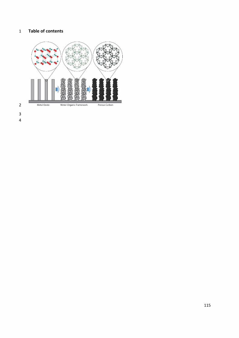
115
Table of contents 1
2
3 4
116
Author Biographies 1 Jongkook Hwang received his Ph.D. from Pohang University of Science 2 and Technology (POSTECH) under the supervision of Prof. Jinwoo Lee in 3 2016. After his first post-doctoral training at Max Planck Institute of 4 Colloids and Interfaces, he moved to Utrecht University where he worked 5 on development of heterogeneous catalysts for preferential CO oxidation 6 in H2. His research interest is synthesis of nanoporous materials with well-7 defined structures and morphologies for energy- and catalytic 8 applications. 9
10
Aleksander Ejsmont received his BS (2016) and MSc (2018) at collaborated 11 universities: Adam Mickiewicz University in Poznań (AMU), Military 12 University of Technology in Warsaw and Lodz University of Technology, 13 followed by a one-year postgraduate research at University of Central 14 Lancashire. In 2019 he started his PhD studies at AMU under supervision 15 of Dr. Joanna Goscianska. His research focuses on the carbon materials, 16 their synthesis, modification and applicability in fields such as adsorption, 17 drug delivery and environmental sciences. 18
19
Ralph Freund is currently a PhD student at University of Augsburg 20 (Germany) under the supervision of Prof. Dirk Volkmer. He obtained his 21 MSc degree in chemistry at the University of Munich (LMU, Germany) with 22 Stefan Wuttke in 2018, investigating the chemistry of metal oxide to 23 metal-organic framework conversion reactions. His currently research 24 focuses on electric-field responsive porous-coordination frameworks 25 constructed from pyrazolate linkers. 26
27
28
Joanna Goscianska is an adjunct at the Faculty of Chemistry of Adam 29 Mickiewicz University in Poznań (AMU). She obtained the Master’s degree 30 in 2005 and doctoral degree in 2009 in the field of chemistry. During her 31 PhD studies, she participated in three research internships at Laboratoire 32 Catalyse & Spectrochimie in Caen (France). In 2018 she became a laureate 33 of the habilitation fellowship „L’ORÉAL-UNESCO FOR WOMEN IN 34 SCIENCE”. Her principal interest is focused on synthesis, modification, 35 characterization of porous materials (e.g. metal oxides, ordered 36 mesoporous silica and carbons) and their application in adsorption 37 processes, catalysis, drug delivery systems. 38
39
117
Bernhard V. K. J. Schmidt completed his PhD in 2013 with Prof. 1 Barner-Kowollik at the Karlsruhe Institute of Technology and a Post Doc 2 with Prof. Hawker at the University of California, Santa Barbara. Afterwards 3 he joined the department of Prof. Antonietti at the Max Planck Institute of 4 Colloids and Interfaces as a Group Leader. Recently, he was appointed as 5 Lecturer in Synthetic Polymer Chemistry at the University of Glasgow. His 6 research focusses on block copolymer self-assembly, metal-organic 7 framework/polymer hybrids and carbon nitride/polymer hybrid materials. 8
9
Stefan Wuttke created the research group “Wuttkegroup for Science”, 10 initially hosted at the Institute of Physical Chemistry at the University of 11 Munich (LMU, Germany). Currently, he is an Ikerbasque Professor at the 12 Basque Center for Materials, Applications and Nanostructures (BCMaterials, 13 Spain). His research is focused on developing methodologies to write and 14 read chemical information onto and from the backbone of hybrid 15 framework materials. In addition, his research interests also include the 16 acquisition of a fundamental understanding of the chemical and physical 17 processes involved in their synthesis and functionalization. 18
19