1 | page assignment top sheet student ref. no
TRANSCRIPT

1 | P a g e
ASSIGNMENT TOP SHEET Faculty of Creative Arts, Technologies & Science
Department of Computer Science & Technology
Student Ref. No: 1019722 Unit Code
CIS000-6
Unit Name MSc Project
Deadline for Submission(s) 26th September 2011, by 12 noon
Student's Surname MUSTAFA
Student's Forename
KAMRAN
Unit Leader's Name Dr Fiaz Hussain
Supervisor’s Name Prof Edmond Prakash
Assignment Details:
Design & Implementation of a Procedure for VFX Content Generation
Instructions to Student: Please note: Work presented in an assessment must be the student's own. Plagiarism is where a student copies work from another source, published or unpublished (including the work of a fellow student) and fails to acknowledge the influence of another's work or to attribute quotes to the author. Plagiarism is an academic offence. Work presented in an assessment must be your own. Plagiarism is where a student copies work from another source, published or unpublished (including the work of another student) and fails to acknowledge the influence of another’s work or to attribute quotes to the author. Plagiarism is an academic offence and the penalty can be serious. The University’s policies relating to Plagiarism can be found in the regulations at http://www.luton.ac.uk/livingandstudying/qa/documents. To detect possible plagiarism we may submit your work to the national plagiarism detection facility. This searches the Internet and an extensive database of reference material including other students’ work to identify. Once your work has been submitted to the detection service it will be stored electronically in a database and compared against work submitted from this and other universities. It will therefore be necessary to take electronic copies of your materials for transmission, storage and comparison purposes and for the operational back-up process. This material will be stored in this manner indefinitely. I have read the above information and I confirm that this work is my own and that it may be processed and stored in the manner described. Signature: ........................................................... Date: .........................................
Extension deadline CAAS agrees that the assignment may be submitted ____ days after the deadline and should be marked without penalty. CAAS confirmation...................................................................................................................
Please leave sufficient time to meet the given deadline and do not leave the handing-in of assignments to the last minute. You need to allow time for any system problems or other issues.
2 | P a g e
Kamran Mustafa 1019722
Design & Implementation of a Procedure for VFX Content Generation M.Sc. Computer Animation Masters Thesis Report Department of Computer Science & Technology
Dr. Edmond Prakash
2010/11

3 | P a g e
ABSTRACT
As a student of M.Sc. Computer Animation I have tried my best to cover all the aspects
of this project.
Being a student is great, but sooner or later I am going to have a transition to "the real
world". I am about to make that transition; graduation is around the corner and I find
myself looking forward to join the workforce. When I look back to my year of study at
the University of Bedfordshire, I am amazed that I have learned much but there is much
more to learn.
The greatest experience I acquired is that with this project I gained a lot of experience to
work on the motion capture and learned new techniques that are used in industry to create
high quality VFX with 3d animation. I have tried my level best to keep the accuracy in
designs and realistic as possible but most important thing is that I have worked for the
first time on motion capture and I am very much successful in generating the output that I
imagined.
The realistic models, usage of MoCaps, mind blowing VFX, environments, materials all
have been done according to the perspective of imitating them to the actual objects. By
doing this most importantly I have passed through several hurdles and bottlenecks that
can appear in the work process.
One of the most important characteristic of my project is that I have not used any special
purpose hardware for my work. All the designing and modeling has been done on simple
core i7 machine without high speed graphics cards or rendering cards. I also haven’t got
any motion capture cameras so I bought pre-captured MoCaps from internet.
Shots that are rendered in 3DS Max were later on blended with the real life footage using
After Effects. After the rendering a lot of work is performed in the Post Production for
generating VFX and doing green screening.
4 | P a g e
ACKNOWLEDGMENT
First of all, I thank Almighty Allah who praises me with the ability to think, work and
deliver what I was assigned to do. Secondly, I must be grateful to my internal Prof.
Edmond Prakash who helped me in this project. Without his professional guidance, I was
not able to complete my project successfully.

5 | P a g e
TABLE OF CONTENTS
ABSTRACT……………………………………………………………………………….3
ACKNOWLEDGEMENT………………………………………………………………...4
TABLE OF CONTENTS………………………………………………………………….5
CHAPTER ONE: INTRODUCTION…………………………………………………….6
1.1 PROBLEM………………………………………………………………...6
1.2 MAIN AIM………………………………………………………………..7
1.3 WHAT I FOCUS TO ACHIEVE?..............................................................7
1.4 VALUE IN OPEN MARKET?...................................................................7
1.5 METHODOLOGY………………………………………………………..8
1.6 TECHNOLOGIES & TOOLS…………………………………………….8
CHAPTER TWO: RESEARCH…………………………………………………………10
2.1 BACKGROUND………………………………………………………...10
2.2 PROJECT PLAN………………………………………………………...10
2.3 ESTIMATIONS………………………………………………………….12
2.4 RELEVANT PRACTICES………………………………………………12
CHAPTER THREE: DESIGN…………………………………………………………..13
3.1 METHODOLOGY………………………………………………………13
3.2 GRAPHICS DEVELOPMENT LIFE CYCLE (GDLC)……………….13
3.3 PHASE DISTRIBUTION……………………………………………….14
3.4 WORKLOAD DISTRIBUTION………………………………………..17
CHAPTER FOUR: SUBSYSTEM DESCRIPTIONS…………………………………..20
CHAPTER FIVE: DESIGN & PERFORMANCE ISSUES……………………………31
5.1 ENTITY RELATIONSHIP MODEL……………………………………31
5.2 ANIMATION……………………………………………………………32
5.3 TWEENING……………………………………………………………..32
5.4 CHARACTER ANIMATION…………………………………………..32
5.5 MOVEMENT OF CHARACTERS……………………………………..32
CHAPTER SIX: PROJECT ESTIMATIONS…………………………………………..34
6.1 PRODUCTION COST…………………………………………………..34
6.2 RENDERING TIME……………………………………………………..35
6.3 DESIGN COMPLEXITY………………………………………………..35
6.4 DEVIATION FROM ACTUAL ESTIMATIONS………………………35
6.5 SYSTEM RESOURCES…………………………………………………35
CHAPTER SEVEN: EXPANDIBILITY, RECOMMENDATIONS &
CONCLUSION…………………………………………………..37
7.1 EXPANDIBILITY……………………………………………………….37
7.2 RECOMMENDATIONS………………………………………………...37
7.3 CONCLUSION…………………………………………………………..37
CHAPTER EIGHT: PROJECT SCHEDULE, REFERENCES & APPENDICES……39
8.1 PROGRESS REPORT…………………………………………………...39
8.2 DATE WISE DISTRIBUTION………………………………………….40

6 | P a g e
8.3 BI-MONTHLY PROGRESS SHEET…………………………………...41
8.4 LOGGING SHEETS…………………………………………………….42
8.5 REFERENCES…………………………………………………………..49
8.6 APPENDICES…………………………………………………………...50
CHAPTER 1
INTRODUCTION
1) INTRODUCTION
The media industry is getting competitive day by day and along the passage of time, new
technologies are arriving for the use of computer generated imagery in films, dramas etc.
Almost every film today has got some animation and special effects for generating the
scenes that are not possible in real life. In this modern era, Animation Designing is
becoming a necessity for almost all kinds of projects when considering a virtual model of
any product or an entertainment movie which is rather much difficult in fact almost
impossible to make happen physically. 3D Modeling and Animation therefore is
becoming a compulsory subject in Computing Departments.
Animation is a sub category of Graphics Designing. In a broader definition of Graphic
Designing, we must say that a virtual image of any real world objects. Graphics are of
several categories. They may be related to web or the Internet. The Graphics may be
useful in the Press for printing or it may be in the form of an animated movie.
The movies like Avatar, 2012, Inception, Transformers, Matrix etc, all have got
wonderful effects. Avatar has pushed new boundaries in the field of 3D animation and
motion capturing. It showed us how we can merge the real life acting with 3d animation.
The motion capture technology has made it much easier to animate the facial expressions
also. Animators does not need to do anything on post production side as the markers
placed on the face capture the facial movements and apply the data on the character’s
face. The output is not that huge that the working beyond creating some particular effect
is.
In my project, I am trying to merge animation along with the real life footage to create a
clip that will involve animation and special effects. Since motion capture device is
expensive and I can’t afford it by myself so I have bought pre-captured MoCaps that I
will use on my rigged characters. The project I selected is related to one of the most
advanced design standards as it included the latest motion capture technique that is much
more advanced than simple 3d animation.
This chapter deals with a brief introduction to the overall system of Development of this
project. Details will be available as the reader advances.
1.1 PROBLEM
My project is slightly different from a typical Computer Animation project. I am here not
7 | P a g e
exactly creating a simple 3d animation but my intentions contain ideas, innovations, and
creative approach at the advanced designing levels in the world of 3D and Motion
Capture.
My main reason for selection of this project is that I wanted to work on something new
that I have learned during my course. It’s not only simple 3d animation but I also wanted
to use motion capture with 3d animation and also generate some VFX so that it could be
a one complete project including everything I have learned here. With my project I may
motivate my junior students entering computer animation field. Moreover with this
project I will also be able to enhance my designing skills at the most professional and
advanced level.
As far as the importance of this field is considered, Graphic and Animation Designing is
considered one of the most highly paid services everywhere in the world and it’s worth is
increasing day by day as the use of computer generated imagery (CGI) is getting popular
in media industry.
1.2 MAIN AIM
Mainly there are two perspectives of why I have chosen Motion Capture Animation along
with VFX content generation as my project.
My first goal is that what I am learning here will not only be useful in my jobs, as
well as if I plan to study or work further in purely motion capture technology then
this is my base and will provide great help in entering the field professionally.
My second goal is that since I am here to generate a motion capture animation
along with VFX. This is not only to make me well versed in Motion Capture; but
also it will attract my juniors to develop their skills in this technology.
1.3 WHAT I FOCUS TO ACHIEVE?
As far as my objectives are concerned following are what I focus to achieve through this
project:
Advancing my Designing Skills.
Making myself compatible with the field of Multimedia.
Learning Motion Capture Techniques.
Maintaining accuracy in my designs which is considered extremely important in
Engineering.
Generation of VFX
Practicing Green Screen Technique
After completing this project, I will be sufficient to design or model any kind of
simulation for machinery, environment or scenarios in 3D environment. Not only this,
but as mentioned in the points above, it will also give a start in Cinematography where I
can use our CAD Graphics Skills to enhance quality and maintain the accuracy in design.
1.4 VALUE IN OPEN MARKET
There are two things what make this project extremely valuable in the market.
8 | P a g e
The Project itself is of high worth in the market as these advanced motion capture
techniques are not commonly used on educational level. This project will help me
out in polishing my portfolio so that I can show my skills in the industry.
Through this project, I may make myself important for Entertainment Industry
including Advertising Agencies, Visual Effects Companies or Television
Channels as well as in the Virtual Simulation Industry where the simulation
designing is being carried out for better production of equipment or construction
of environments or factories without investing resources.
1.5 METHODOLOGY
Now this is how I have made it possible to accomplish my goals and objectives. Details
of this section will be discussed later. It is here just to give an idea of our work flow.
To achieve what I projected, i have made a Work Flow diagram named as Graphics
Development Life Cycle (GDLC). This diagram can be credited as my scheduling
algorithm. This workflow model deals with all the steps/phases that are important and to
be implemented in process.
1.6 TECHNOLOGIES & TOOLS
My technology is concerned with the concept of designing in a predefined but unlimited
3d world. My project contains especially modeled objects using mesh techniques. This is
the most basic technique just like writing a computer program in assembly or coding a
webpage in HTML rather than using Adobe Dreamweaver to design it. This mesh
modeling technique gives me very precise architecture and command over the objects. As
will be discussed later, the tools are same as used for Modeling, in the market all over the
globe. Mainly my designing tools include:
3D STUDIO MAX v 2011 by Discreet Autodesk
A special 3D modeling and animation designing software used all over the world to
design 3D models of any lively imaginative object. This software provides us the power
to use computer to make virtual world as close to the real world it could be.
ADOBE AFTER EFFECTS by Adobe Systems
This software is basically used for applying special effects and finishing to the movies as
well as the green technique is also done using this program.
iCLONE v 3.0 by Reallusion
A special 3D animation and visual effects software used to animate complex 3D
characters along with some visual effects.
POSER v 7 by Meta Creations
Specifically a 3D character animation software that is used to animate characters along
with their props.
ADOBE PHOTOSHOP v CS3 by Adobe Systems
9 | P a g e
Used for designing of textures plus any desired still pictured if required in the movie.
SOUND DEVELOPMENT SOFTWARES
Most of our audio sounds including effects, recording and music are developed using two
software:
1) Sony Vegas 10.0 HD Platinum
SONY VEGAS by Sony Pictures
Very effective and light software used for both sound and video editing along with some
transitions and audio effects. This software supports a huge variety of file types to import,
edit and export.
10 | P a g e
CHAPTER 2
RESEARCH
2.1 BACKGROUND
This chapter deals with the usage of scenarios. What I mean is that it is one the
noteworthy chapters that include the preface of the physical project. This will tell about
how the project commenced, what was projected to accomplish, what were the initial
hindrances I faced in the starting of the project. How were they solved? It also includes
how the project can be useful to the end user, what will it serve to the people and how can
it help me out in the industry as was also discussed in the previous chapter. Since I have
mentioned several times in my past documents that my project is slightly different from
the conventional projects of computer animation therefore my perceptions and
documentation style will be considerably different as the general used commonly. One
thing is mentionable that this chapter is a general description of my work without going
in depth.
2.2 PROJECT PLAN
The overall project plan is divided into phase wise distribution mechanism. The major
impact of this workflow on my working was of great help in synchronizing my work with
time. Although, the task was not easy to execute in such low resources where I have got a
single i7 machine but I tried my level best to generate the best possible output from my
resources. I have divided my project into two phases which commence just after the
project has been approved and ends with the submission. Both of these phases are
subdivided into separate modules. These modules provide the basis of a linear as well as
hierarchical approach to my project workflow.

11 | P a g e
Figure 2.1
This process model is referred to as Graphics Development Life Cycle (GDLC) will be
discussed with details in Chapter – 3 – Working Strategies and Activities.
Step Wise Distribution of Single Phase
The main objectives that I was ought to achieve were to carry out the project with a
preplanned architecture to make it more professional and regularize the work with time
frames in order to complete it successfully on time. As shown in the figure 2.2 after the
commencement of each phase, I made the estimations of the work distributed in the
categories in their respective module. Now following that module I started related tasks
to carry out.
Worked, Tested & Verified
Phase 1 Completes
Phase 2 Begins
Worked, Tested & Verified
Project Ends
Phase 1 Commences
Proposal Acceptance
Project Submission

12 | P a g e
Figure 2.2 shows my work plan
Time by time as the project commenced, I looked after my resources as being sufficient
or not. If they were considered in-sufficient then the workload was re-sequenced. Later
work was carried out and tested for quality. On success, the phase was finalized and I
moved on to the next phase.
2.3 ESTIMATIONS
These estimations include Time Duration, Cost Involved, checking out the availability of
resources, observation of market trends, as well as probability of future problems that are
expected to be faced during the project work being carried out.
Time Duration
As I have decided to make the output merged of motion capture, VFX and 3d
Phase Commeces
Testing the Output
Are the tests
successful?
NO
YES
Project Estimations
Priority wise Distributions
Sequencing Workload
Resource Management
Are Resources Sufficient?
Working on the project
Finalizing the output of particular phase
End of Phase
NO
YES
13 | P a g e
animation so this time duration completely depended on how complex are my
designs and how much time they take to render and what kind of effects I am
applying. This topic is further discussed in Chapter 6.
Costs Involved
My main objective was to perform the work in low cost and limited resources so
as to make it more practical. After aggregating all the equipment that I bought for
the project including Portable DVD’s for writing the finalized output, USB for
carrying data as well as some printing expenses, I have spent a sum of £50
approximately.
Resource Management
Resource Management was equally important to get a complete and working
picture of the Movie. Most of my work load was divided according to time and
priorities, the parts that included more time for rendering and generating were put
on top priorities as compared to the tasks that don’t needed much time.
Observation of Market Trends
This is what I considered the greatest factor to be focused while making my
project. As market is concerned, I have tried to build my project with most
professional standards. These standards include the designing, usage of up to date
software tools and applying most modern techniques to complete the
cinematographic image sequences.
2.4 RELEVANT PRACTICES
Initially when the project started, there were several things that I have to take notice of.
One of them was the training to accomplish the goals. For this purpose several tutorials
were practiced by me in order to get hands on these techniques.
CHAPTER THREE
DESIGN
This chapter deals with the design strategies of how the work has been carried out during
the period of preparation of the project. It tells us about the main activities that were
involved in advancing the project. This chapter also includes a detailed study of GDLC
(Graphics Development Life Cycle) which I have considered my route to
accomplishment of my objectives. The methodology is discussed in general to give a
knowhow of the project to the reader.
14 | P a g e
3.1 METHODOLOGY
The main idea of my characters was not based on anything really but it was just a mind
built sketch to show any character as the main purpose was not to focus on the character
but on its movement through motion capture. I just viewed some robotic and human
models in order to get an idea of the structure and anatomy of these models. Most of my
emphasis was on rigging and animation instead of modeling. Some models were designed
to use in After Effects in order to generate the VFX on real life images and footage.
Mainly the techniques that are applied for the modeling of the characters and objects are
the Polygonal modeling or Mesh modeling depending upon the geometry of the model.
Also I tried to make the materials by the use of Photoshop so accurate to give the most
realistic effect. Sometimes I have used materials instead of creating the whole 3d model
as there is no need to focus that particular object and the material was giving same
appearance as the physical model.
Moreover I created bones structure for attachment of the physique of the character,
sometimes biped is also used instead of bones. This is done to provide the movement of
characters more realistic and also to apply MoCaps to the models. The characters are
designed using Polygons / Meshes.
As you can see in the GDLC on the right whole of my process goes sequentially as well
as hierarchically. The main aspect of my work is priority assigning to the tasks. My work
has been distributed in priorities so that I can start the more time consuming tasks first.
Using this approach I can carry my work in parallel so that more and more of the work
can be completed in the least possible time. It is notable that scenes will not be rendered
sequentially but they will be combined later into one single movie with all the special
effects and text etc.
3.2 GRAPHICS DEVELOPMENT LIFE CYCLE (GDLC)
Our project development cycle referred to as GDLC i.e. Graphics Development Life
Cycle can be explained as a predefined sequence of steps that was built to help me in my
project development and management to accomplish the goals more precisely and
accurately.
3.3 PHASE DISTRIBUTION
The GDLC has been distributed in two phases. These phases are concerned with the
nature of work that is being carried out in the specific process. These phases are as
follows:
. Modeling & Animation Phase
. Rendering & After Effects Phase
If we closely observe the phases, it can be seen that each phase is distributed in modules
of work. These modules are distributed inside the phase in a sequential pattern which

15 | P a g e
refers to the work done stepwise. It was also discussed in the previous topic, in the
GDLC. For sake of correctness in the animation these phases are interlinked through
distinct paths to return to a specific module as desired.
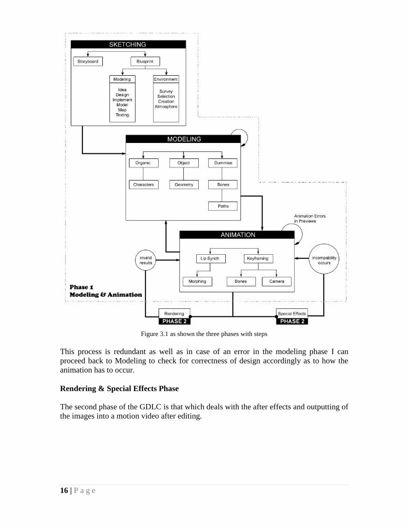
Modeling & Animation Phase
This is the first phase of GDLC. The first module is SKETCHING (Module). This refers
to the initialization of the process and shows how the work starts and allows me to fulfill
my initial requirements before further proceeding at advanced levels in the hierarchy. In
the sketching process, after determining the Storyboard; comes the Blueprinting process.
Note that Blueprints are the rough sketching and pictures made for anything that is ought
to be modeled in the 3D space. It required the survey for the objects and the
environments to be designed. After the Blueprinting / Sketching is been finalized we
process to the MODELING (Module).
There are basically 3 main approaches to the models in our project.
1) Organic Modeling – refers to the modeling of living objects
2) Objects – refers to the Geometry i.e. real time objects other than Living
Beings to be modeled
3) Dummies – Helpers designed to assist in the animation and movement of
various objects in some specific manner.
Then comes the ANIMATION (Module). Animation is the intermediate process model
on which the movie depends at the most. It allows us to use the modeled objects and
helpers to produce some motion picture or a movie. It involves movement and
synchronization of movement with sound (LIP SYNCH) and surroundings.
16 | P a g e
Figure 3.1 as shown the three phases with steps
This process is redundant as well as in case of an error in the modeling phase I can
proceed back to Modeling to check for correctness of design accordingly as to how the
animation has to occur.
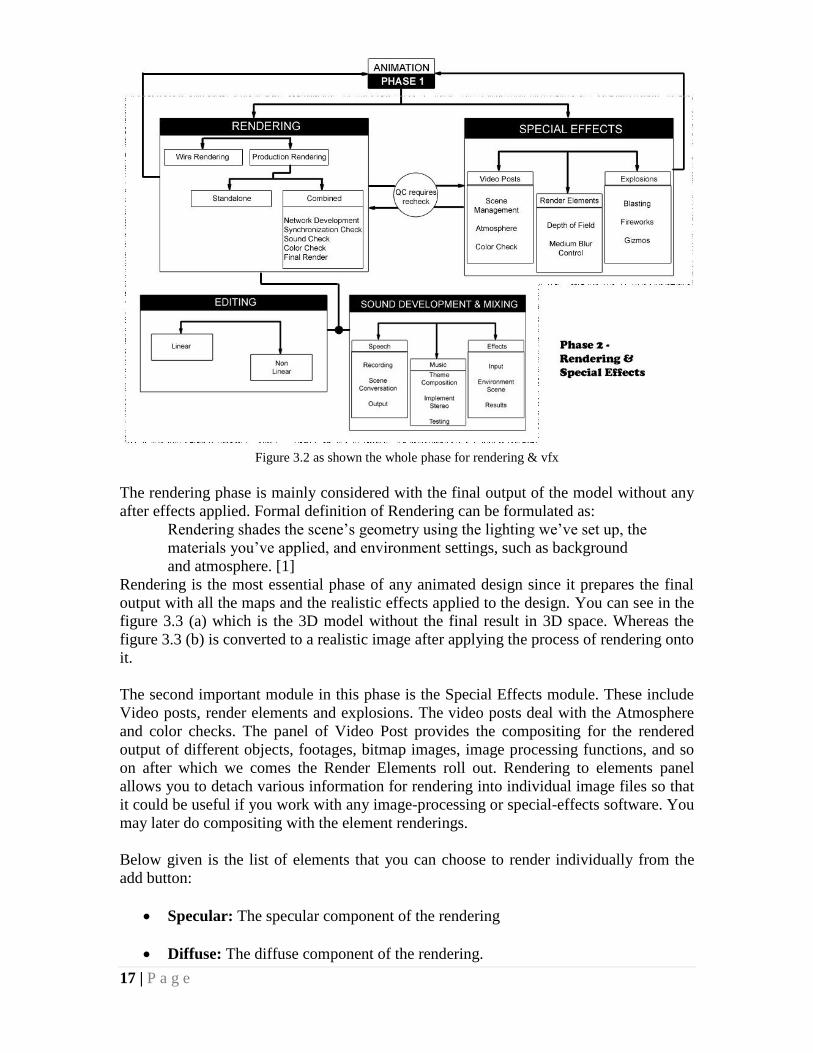
Rendering & Special Effects Phase
The second phase of the GDLC is that which deals with the after effects and outputting of
the images into a motion video after editing.
17 | P a g e
Figure 3.2 as shown the whole phase for rendering & vfx
The rendering phase is mainly considered with the final output of the model without any
after effects applied. Formal definition of Rendering can be formulated as:
Rendering shades the scene’s geometry using the lighting we’ve set up, the
materials you’ve applied, and environment settings, such as background
and atmosphere. [1]
Rendering is the most essential phase of any animated design since it prepares the final
output with all the maps and the realistic effects applied to the design. You can see in the
figure 3.3 (a) which is the 3D model without the final result in 3D space. Whereas the
figure 3.3 (b) is converted to a realistic image after applying the process of rendering onto
it.
The second important module in this phase is the Special Effects module. These include
Video posts, render elements and explosions. The video posts deal with the Atmosphere
and color checks. The panel of Video Post provides the compositing for the rendered
output of different objects, footages, bitmap images, image processing functions, and so
on after which we comes the Render Elements roll out. Rendering to elements panel
allows you to detach various information for rendering into individual image files so that
it could be useful if you work with any image-processing or special-effects software. You
may later do compositing with the element renderings.
Below given is the list of elements that you can choose to render individually from the
add button:
Specular: The specular component of the rendering
Diffuse: The diffuse component of the rendering.
18 | P a g e
Self-Illumination: The self-illumination component of the rendering.
Reflection: The reflections in the rendering.
Refraction: The refractions in the rendering.
Shadow: The shadows in the rendering. This element helps to save black-and-
white shadows only.
Atmosphere: The atmospheric effects in the rendering.
Blend: A custom combination of the previous elements.
Z Depth: This is the grayscale representation of the Z depth, or depth within the
view of objects present in the scene. The objects that are closer appear in white
and the depth of the scene in black. The intermediate objects are shown in grey,
the darker the deeper the object is within the view.
Alpha: This is the grayscale representation of the alpha channel, or we can say
transparency of the scene. Transparent pixels appear in white color (value=255)
and opaque pixels in black color (value=0). Translucent pixels appear in gray
color. The darker the pixel, the more transparent it is.
The Alpha channel is useful for the compositing of elements.
Background: This is the background of the whole scene.
The other elements do not include the background. This element is useful if you want to
use some particular background in whole scene.
3d Max do not trims the background with respect to geometry so the objects placed in the
scene must be kept with proper color correction and angles so that they could blend easily
with the background.
Ink: This is the Ink component (borders) of Ink ’n Paint materials.
Paint: This is the Paint component (surfaces) of Ink ‘n Paint materials.
It is important to mention that I have placed render elements into the special effects
category mainly because the Render Elements tab provide a customized rendering
options which can be produced up to the requirement. Hence it may be considered
separate from conventional rendering. This phase also includes the final editing and
sound engineering to create a natural effect in the movie.
3.4 WORKLOAD DISTRIBUTION
The work was divided into time segments with respect to priority and time consumption.
For example the 3D modeling process that took most of the time was started at the very
first before anything else. This modeling was then followed by rendering of the shots and
saving the shots for future use. After modeling and rendering I look on towards merging

19 | P a g e
and green screening on Adobe After Effects.
Network Rendering
When the project proposal was submitted, it was the main thing in my mind to perform
the work on the cluster of computers. For me to implement this feature; I developed one
network at my house. All necessary installation was carried out on me and my friend’s
system from scratch to prepare both of pc’s them for being able to conduct the process of
Network Rendering. Backburner, a Network Renderer developed by Autodesk Inc. was
used on these computers to fulfill the speed gap as well as the project requirements for
the successful accomplishments.
Figure 3.7 Network Rendering [1]
The major procedure that the network renderer follows is that each workstation is
assigned a task of single frame and different frames are sent to the different workstations.
There are several advantages of using backburner rather than rendering on a single PC.
First of all, the time duration cuts exponentially with the speed getting higher due to
parallelism. Secondly incase if a terminal gets down, the respective job is transferred to
some other terminal hence provides reliability in work and satisfaction to some extent
against hazards. Network rendering uses multiple computers to perform rendering. Even
20 | P a g e
a small network of two or three PCs can save a lot of rendering time and help you in
completing the project within the specific time. It is basically designed to render anything
that is been setup in your file; that is, the viewport will be rendered, the camera views are
rendered, and vice versa as saved in the main source file.

21 | P a g e
CHAPTER FOUR
SYSTEM SUBDESCRIPTIONS
This section explains the detailed description of raster and vector graphics / images. It
also includes detailed notes on modeling, animations, lights, cameras and materials. My
subsystem includes the designing of various objects and skills of animating them to give
out a realistic effect. This section only presents the tools used and their descriptions
inside the software other than the designing, modeling and animation of specific objects
which will be discussed in the next chapter. In short, a complete know-how of the 3D
space and concepts involved in various kinds of animation including the special effects
production will be discussed herein. Most of this chapter has been collected from
different sources including Libraries, Internet and Max Tutorials to develop the major
concepts in the reader before proceeding to the next chapter.
Computer Graphics
Computer Graphics is the field of information technology in which computers generate
two and three dimensional images that are needed in research projects, media industry,
artists, architectural uses and many more. Due to computer graphics, it is very easier now
to use any package due to its GUI (Graphical User Interface). Computer graphics has
replaced the need to memorize difficult syntaxes and commands to perform operations
but we can very easily perform those tasks with simple clicks on different buttons that are
represented in the form of computer graphics.
Raster & Vector Graphics
Raster Graphics are those in which the images are generated and stored in the form of
tiny dots that are known as pixels in graphics language. These pixels are arranged in rows
and columns. In raster graphics, these kinds of images are treated as a bunch of pixels.
Pixel is a short form of Pixel Element which is also called as Pel sometimes. In memory,
the bit is the smallest unit, so in the same way, in graphics, the pixel is the smallest
element that is used in creating graphics.
We can also represent image as a combination of two colors. For e.g.: The image in the
range of gray color only.
Vector Graphics is another part of computer graphics that is used to determine the length,
directions in which the lines will be drawn etc with the help of mathematical descriptions.
In vector graphics, lines are used to create drawings instead of pixels as in raster
graphics.
3D Concept
What is the common thing between all the objects present around us? There are about
two or may be three things that are common in these objects. May be these things are
very much same or very different from each other.
22 | P a g e
These things are the length, width and height. In 3D (shorted form Three Dimensional)
space, these three dimensions are known as X, Y and Z axes that corresponds to width,
length and height. If any object has got all these three components i.e. X, Y and Z axis,
than it is known as 3D object otherwise its 2D or two dimensional.
World Space Origin & Object Space
Vertices that are represented by dots basically define the location of all points present in
3D space at some specific distance from the starting point which is called World Space
Origin. The main concept is that any time we move, scale or rotate the object, its relative
distance from the world space changes which gives the appearance of movement. The
relative changes from the world space origins are carried out by the means of modifying
edges, faces, polygons or elements. World space is the main universal coordinate system
that is used to track objects present in the scene. If you look at home grid that is in the
viewports, you will notice the world-space coordinate system. All objects that are present
in your scene are located in world space by their respective position, rotation, and scaling
(their transforms).
In comparison, object space tracks the location of everything that is applied to an object.
The exact location of all vertices of an object, the position of modifiers, mapping of co-
ordinates, and materials, everything is defined in the object space.
Modeling
The first step in a making an animated motion picture is the creation of 3D objects that
will later be used to present the movement capabilities. The skin or surface of an object,
such as teapot, is represented either as polygons or as a series of curved surfaces,
normally triangles. The points present on object surface that are called vertices (as
mentioned above), are represented in our computers by their spatial coordinates. Rest of
the characteristics of the model, like the color of every vertex and the direction that is
perpendicular to the surface of each vertex is called the normal. Polygons are not used to
create smooth surfaces; so models that have more details requires a huge number of
polygons to generate an image that looks smooth and natural.
Building models is actually sculpting of the digital 3D data. Normally a traditional
sculptor always starts with his raw form like wood, stone or marble. Then applying
certain techniques of chipping away at the mass gradually, he makes some desired
sculptor of a real world object as a final result. Similarly to design a 3D model the
modeler also always starts with a raw form, usually a box or a sphere on which some
cutting, extruding, beveling or molding is applied to make a 3D object. The modeling of
the models used in our movie will be presented in the next chapter with detailed views.
Basic Tools for modeling in Max
The Objects tab panel lets you create a number of geometric primitives as well as
NURBS surfaces, Bones and dynamic objects.
The basic objects available in max for three dimensional objects after modification are:

23 | P a g e
Box
Cone
Sphere
Geosphere
Cylinder
Tube
Torus
Teapot
Pyramid
Plane
Hedra
Animation
Animation came from the inspiration of human vision. If you see a series of still images
that are in some connection with each other in quick succession, then your brain will
perceive those images as a one continuous motion. Each image that is present in a
timeline is called a frame.
In previous times, the major problem that came in creating animations was that the
animator needs to generate a huge number of keyframes. It was depending upon the
quality that is required, sometimes an animation of one minute may require between 720
and 1800 individual still images. Drawing of images by using hand is a difficult and time
consuming job. This is the point where key framing comes in.
Mostly frames present in an animation are routing, the change in previous frame is
directed towards the next frame after it, and they all proceed step by step to some
predefined goal. In early times, the animation companies realized that if they allow their
animators to draw only the important keyframes than they could save a lot of time and
increase the productivity too. The team under the animators will then check the frames
that are needed between those keyframes.
Now aday s, software works for us as our assistant. We perform like an animator and
hence we create only the keyframes that mark and record the beginning and the ending of
each transformation. The software then calculates the values present in between these
keyframes that result in generation tweened animation.
Traditional Animation Method
In early times, the most difficult task in creating an animation was the efforts of the
animator that needed to generate a huge number of frames. Sometimes, the animation of
one second may require 30 individual images depending upon the requirement of the
animation and its quality.
Max's Key-Frame Animation
After we drawn all the keyframes and the tweens, we need a rendering that will generate
final images.Once all of the keyframes and tweens were drawn, the images had to be
24 | P a g e
inked or rendered to produce the final images.
The first and last keyframes record from the beginning of the transformation till the end
of it. These transformations are applied on the objects or elements that are present in the
scene.
Suppose you have got a teapot which is not yet animated. If we turn the Auto key to on
and move the teapot from frame 0 (zero) to frame 20 (twenty) and also apply some
rotation on x-axix, say 45 degrees. What will happen than key will be created between
frame 0 and 20 for rotation as well as movement.
Timings in Animation (Standards)
Animation has got different formats. The most common are two formats that are used
widely by the professionals. First one is film that is created at 24 FPS (frames per second)
while the second one is NTSC (National Television Standards Committee) which is
created at 30 FPS. 3d Studio Max is based upon time. It stores your times and animation
values with its internal precision of 1/4800 of a second. We can change the configuration
for time display as per our requirements.
Lighting
The 3d Studio Max has got lighting just as the normal life lighting works. Lights are
objects that virtually imitate the behavior of our daily life lights such as lights in our
home of office, the instruments of lighting that are used in media industry like TV
channels etc, and also the sun itself in the 3D world (mostly). Every light object cast their
own light in very different way, with respect to different real-world light sources. Lights
are extremely important in any 3D design. A good strategy using the lights can upgrade
the quality more than expected; conversely a poor level of Lighting can destroy the
quality of the output of even a well modeled object.
If you don’t use any lights in your scene then the scene will be shaded or rendered by
default lighting. We add lights in our scene to make it more realistic. With the use of
light, the clarity of objects is improved. Also apart from general lighting, we can also use
lights to project specific objects.
The Light objects as put in the scene, they replace the default lighting. Default light
doesn’t work if you create even a single light in your scene. In the same way if you again
delete all the lights, the default light will turn on automatically. Default lighting includes
two invisible lights arranged in a way that one is placed left side above in the scene and
second one is placed bottom side and right of the scene.
Lights Available in Max
There are three kinds of lights in 3d Studio max that are stated as standard light, daylight
and photometric light. Each type is shown as light object in the viewport. They have got
many parameters same including the shadow generators. But the daylight and the skylight
have different parameters.
25 | P a g e
Standard Lights
The Standard lights are basically computer-based light objects which simulate our daily
life lights like sun, lights used in instruments, lamps or lights used in our homes. Each
light object cast the lights in its own way with respect to the light sources and objects
present in the scene. Standard lights don’t have physically-based values whereas
photometric lights have got these. There are a total of six types of standard light objects:
Target Spot
Free Spot
Target Direct
Free Direct
Omni
Skylight
Daylight Lights
Daylight lights are basically made up of two components: the sun and the sky. This
system uses these two components to simulate sunlight.
Below given are the photometric daylight lights:
IES Sun
IES Sky
We can use the daylight lights manually in the scene but if we require the best results, its
better that we use these lights with respect to the Daylight system. Daylight system
merges the two daylight components that are sun and sky which allows you to set the date
and the time positions along with the light type you want to use.
Photometric Lights
Photometric lights use photometric (light energy) values that allow us to define light
more accurately and perfectly as they are present in the real world. We can modify their
intensity, color temperature and other characteristics of the real-world lights. We can also
render the scene to visualize and refine our scene. There are a total of six kinds of
photometric lights:
Target Point Light (Photometric)
Target Linear Light (Photometric)
Target Area Light (Photometric)
Free Point Light (Photometric)
Free Linear Light (Photometric)
Free Area Light (Photometric)
Features of Max Lights
Intensity
HSV value of the light is known as its Intensity. The maximum value is (255) at which
the light is brightest, whereas the (0) is the minimum value at which the light is
completely dark
A surface is fully illuminated when the angle of incidence in 0 degrees (that is, the light
26 | P a g e
source strikes the surface perpendicularly). There is no attenuation, and the light is white.
Attenuation is affected if we increase the angle of incidence or if the light has got some
color then the intensity of the surface can be minimized.
Angle of Incidence
3d Studio Max always uses a vector directing from the lighting object towards the face. It
also includes face normal for the calculation of the angle of incidence.
We can say that the orientation and position of the lights with respect to the object are the
things that control the angle of incidence.
Attenuation
3D Studio Max has got no attenuation as a default. For using attenuation in order to
render some scene or shading, we need to turn it on for one or more than one lights.
Every light in 3d max supports attenuation. 3d max allows us to control the attenuation
that from which point it should begin and where it should end up.
Reflected Light and Ambient Light
If we render the scene with max’s default lighting, than we cannot calculate the effect
that could be generated from the lights reflected from the objects present in the scene.
This is why we often needs to add more lights in comparison with the scene that is
lightened up by default lighting in our real world. We can use radiosity if we want to
generate the results of the reflected lights.
The Ambient light affects the contrast. As higher we take the value of Ambient light, the
lower the value of contrast will be. If we want to tint the scene then also the color of
Ambient light is changes that affect the tint property. Sometimes Ambient light works as
a bounced light and gets its color from the objects that are present in the scene.
Color
Normally the color of the lights comes from the process that generates the light. For e.g.
suppose the lamp that is casting orange-yellow light, some cast blue-white light etc. The
color of light also depends upon the medium by which the light passed through. For e.g.
fog in the atmosphere in light blue day light.
Cameras
Cameras in our daily life use the lenses in order to focus the light that is reflected by the
objects or by the scene on a focal plane as this plane as got a light-sensitive surface.
Focal Length
Focal length is the distance that is present between the lens of the camera and the light-
sensitive surface. These deals with the scene of how much area should be covered and
recorded. The focal length with lower value includes the wider scene in their angle as
compared with the one with higher focal length. But one thing to notice is that focal
length with lower value shows very good details of distant objects.
This is always measured in millimeters. Normally photographers use 50mm focal length
lens. The lens having lower value then 50mm is known as a short or wide0range
photography. The lens with more than 50mm focal length is known as long or telephoto
27 | P a g e
lens.
Field of View (FOV)
The field of view (FOV) allows you to control that how much area of the scene is visible.
The FOV is measures in degrees of the horizon. The FOV is directly in connection with
the focal length. For e.g., a 50mm lens shows 45 degrees of the horizon which means that
the longer the lend will be, the narrower the FOV will be. Similarly, the shorter the lens
will be, the wider the FOV will be.
Cameras available in Max
Cameras are used to represent a scene from specific point of view. In the camera
viewport in 3d max, we can modify the camera positions because it gives us a view as if
we are looking from its lens. This viewport is helpful in creating geometry or if we need
to render a scene from specific any view. We can use more than one camera in order to
render scene from different views.
3d max has got two types of cameras:
The first one is target camera. This is normally used to view the area present around a
target of the camera. When we create a target camera in the scene, we see a two parts of
the camera. One is camera itself and the one is its target that is represented by a small
white box. When you create a target camera, you see a two-part icon representing the
camera and its target (a white box). Both of these parts of the target camera can be
animated individually. Target cameras are helpful in the scenes in which cameras has not
got any path to follow.
The second one is Free camera. This is used to view the entire area present in the
direction of the camera. When we create a free camera, it is represented by a single part
as a camera icon and its angle. The icon of this camera is same as that of target camera
but this one is without the target. Free cameras are useful when we have got a path for the
camera to follow.
Materials
Materials are the property that helps to visualize the objects in a way in which it reflects
or transmits the lights. We can play with textures, maps, reflections, refractions etc within
a materials panel. Materials can also be defined as the data that is used to apply on
surface or phases of objects so that how that objects appears upon rendering. Materials
always affect the original color of the objects, the glossiness, the opacity and many more.
Material Editor
If managed properly, materials can provide realistic look and feel to the objects.
Materials works in connection with light properties, shading and rendering gives us the
feel of how the scene will look after rendering or we can get an idea of how that looks
like in real-world. It also provides us functions in order to create and modify the maps
and the materials.
We can apply textures and maps to modify the surfaces of the objects and to make them
look realistic. The properties include texture, bumpiness, refraction, reflection, opacity
etc. Many basic properties can be modified using a map. Any sort of image can be used
as a map which will create some patterns based upon the parameters that we set. It has
28 | P a g e
also got a rat-trace map that is widely used for creating realistic reflections and
refractions.
2D Maps
2d maps are the two-dimensional images that we map on the surface of our objects or we
can also use as a scene background in environment map.
Bitmap: It is basically a bunch of pixels that is saved as one still-image file.
These formats include .jpg, .png, .tga etc or any animation file format such as .avi,
.mpg, .flv etc.
Bricks: This is used to create bricks like material with specific colors that we
define or any other tiled materials. We can apply our colors and material maps.
Checker: It is used to combine any two colors in a pattern of checker. We can use
map instead of color also.
Combustion: This is package that works in connection with discrete combustion.
We can paint our bitmap directly or also we can paint our object directly and
result will update the material editor and the scene.
Gradient: Used to create the linear or radial ramp of three colors.
Gradient Ramp: Used to create great ramps, in which we can use as many colors
as we want, as many maps as we want and blends as we want to use.
Swirl: Used to create swirled (spirally) patterns of two colors or maps.
3D Maps:
The patterns that are generated in all three axes i.e. X, Y and Z are called as 3D maps.
The following is a list 3d maps that are available in 3ds max:
Cellular: Generates a cellular pattern that's useful for a variety of visual effects.
Including mosaic tiling, pebbled surfaces, and ocean surfaces.
Dent: Generated three-dimensional bumps over a surface.
Falloff: Generates a value form white to black based on the angular falloff of the
face normals on the sirface of the geometry. The fallof map provides greater
flexibility when creating opacity, falloff effects. Other effects include
shadow/light, distance blend, and fresnel.
Marble: Simulates the grain of marble with two explicit colors and a third
intermediate color.
29 | P a g e
Noise: Noise is a turbulence pattern in a three dimensions. Like checker in 2d, it
is based on two colors, either of which can be mapped.
Particle Age: Alerts the color (or map) of a particle based on the particle's life.
Particle MBlur: (MBlur is short for Motion Blur). Alerts the opacity of the
leading and trailing ends of particles based on their rate of movement.
Perlin Marble: An alternative procedural marble map with a turbulence pattern.
Planet: Simulates the contours of a planet as seen form space.
Smoke: Generates fractal-based turbulence pattern to simulate the effects of
smoke in a beam of light, or other cloudy, flowing mapping effect.
Speckle: Generates the speckled surface for creating patterned surfaces that can
simulate granite and similar materials.
Splat: Generates fractal pattern similar to splattered paint.
Stucco: Generates a fractal pattern similar to stucco.
Water: Creates watery or wavy effects by generating a number of spherical wave
centers and randomly distributing them.
Wood: Creates a 3D wood grain pattern.
Other Maps
Compositor Map Types
These are two types of compositions. In image processing, a compositing image
superimposes two or more images to combine them.
Composite: Composites multiple maps. Unlike Mix, composite doesn't have
explicit controls for the amount of mixing. Instead, it bases the mix amount on the
maps alpha channel.
Mask: A map that controls where a second map is applied to the surface.
Mix: Mixes two colors or two maps. You can adjust the amount of mixing of
mixing using a blend level you specify. The blend level can be mapped.
RGB Multiple: Combines two maps by multiplying their RGB and alpha values.
Color Modifiers: These color modifiers are included:
Output: Applies bitmap output functions to parametric maps, such as Checker,
that don’t have these settings. These functions adjust the colors output by the
30 | P a g e
map.
RGB Tint: Tints the color of a map based on red, green and blue values.
Vertex Color: Displays the effects of assigned vertex colors in the rendered
scene. You assign vertex colors from the editable mesh.
Other
These include the map types that generate reflections and refractions.
Flat Mirror: Generates reflections for flat surfaces. you assign it to faces rather
than to the object as a whole.
Raytrace: Creates accurate, fully retraced reflections and refractions.
Reflect/Refract: Generates reflections or refractions automatically, based on
surrounding objects and the environment.
Thin Wall Refraction: Generates refractions automatically, simulating objects
and the environment as seen through a refractive material such as glass or water.
UVW Wrapping Coordinate Channels
Every object in the scene can acquire 1 to 99 UVW mapping coordinate channels. The
mapping by default will always be UVW 1.The map modifier of UVW can export the
coordinates to any of these channels. The maps present in material can use any UVW
channel.
Compositing
After all the models are completed and checked, the scenes are rendered into short
sequences of animation called clips. These clips may be in the form of avi, tga
(sequences) or some other codec and saved separately. Now comes the compositing
phase.
Each video track in the Timeline window contains an alpha channel that stores
transparency information. All video track frames are completely transparent except where
you've added opaque content such as video, still images, or titles. You can make areas of
opaque content partially or completely transparent by adjusting a clip's alpha channel or
applying a matte or key to a clip. Clips on upper tracks cover clips on lower tracks except
where alpha channels indicate transparency. Adobe Premiere Pro composites clips form
the lowest track up, and the final video frame is a composite is a composite of clips on all
visible tracks. Areas where all tracks are empty or transparent appear black.
Compositing can be taken as a general term to refer to the videos and sound mixing
operations and arranging different scenes in orderly fashion so as to get a meaningful
motion video. We will not be going in extreme detail to these concepts but to get an idea
it is good the mention them.
Apart from general definition, compositing is the process of creating a composite image
by superimposing multiple images. Because video frames are completely opaque by

31 | P a g e
default, compositing requires that parts of video frame be transparent. When part of a clip
is transparent, transparency information is stored in the clip's alpha channel. You can
combine partially transparent clips using stacked tracks, and use a clip's color channel to
create and effect in a clip on a lower track. It includes the following concepts.
Alpha Channel
It is the channel that defines transparent areas for the clip that contains the channel. The
alpha channel is an extra channel in addition to the visible color channels (such as RGB).
While the alpha channel indicates transparency, the channel itself is usually hidden. The
alpha channel can store the clip and its transparency both, without affecting the original
color channel of the footage. You can also ignore an existing alpha channel and use
Adobe Premiere Pro transparency effects to create a new one. When you view the alpha
channel in the Monitor window (see choosing a Display Mode setting), white areas
indicate opacity, black indicates transparency, and gray indicates partial transparency.
Because an alpha channel uses shades of gray to store transparency information, some
effects can apply a grayscale image (or the luminosity values of a color image) to an
alpha channel.
Mask
Sometimes used as another word for alpha channel; also describes the process of
modifying an alpha channel.
Matte
The Matte is the property by which we can identify the areas that are transparent in the
clip or in the image. We use matter generally if we have got a channel or a clip that
identifies the transparency area more better than the alpha channel or sometimes if the
clip or image don’t have the alpha channel included.
Keying
Keying is a technique in which we define the transparency by any particular color or the
brightness to an image. The pixels that match with the color of the key becomes
transparent. We use keying to remove the background with any uniform color, for e.g.
green screen.

32 | P a g e
CHAPTER FIVE
DESIGN & PERFORMANCE ISSUES
This is an extension of the previous chapter. After the reader gets an idea of all the tools
and concepts used in the system, we proceed with the arrangement of the scenes in the
movie and the making of the objects will be discussed. In the starting of this chapter the
ER model has been presented and according to the flow of this model goes this chapter in
sequence. Note that this chapter only briefs the designing procedures and their
performance & impacts on the results in the project without going deep down the rabbit
hole like Alice.
5.1 Entity Relationship Model
According to the entity relationship diagram shown in figure 5.1 the whole of our process
is mainly dependent upon priorities. It starts with the storyboard that has been made in
accordance with the specified requirements and standards.
Figure 5.1 as shown the flowchart of my work priorities
The scenarios are of equal importance because on the basis of these situations the models,
animation and environments are designed, rendered and after composition converted into
a full featured movie.
Storyboard Requirements &
Standards
Scenarios
Animation Models Environments
Complexity Materials/Maps Position Cameras Time Objects
Shapes Space
Production
Rendering
Compositing Special Effects
Special Effects
Decide Decide
Decide Create & Verify
33 | P a g e
5.2 Animation
Animation is the major part of my project and is the last module of Phase 1. According to
the GDLC discussed in Chapter 3, the animation in my process is a repeated approach to
which I return when required.
Conventionally, animation is the process of giving life to objects in the 3D world
(mostly) if 3D animation is considered. Animation engages various types of movement. It
may be as simple as a ball bouncing, or as difficult as a person speaking virtually on the
words. Be it a simple one or something complex the main concept behind the animation
is the change of image periodically to show something in the action (the concept of CEL
animation). Some of these techniques are discussed below:
5.3 Tweening
Tweening is a simple concept. I will not go in details here since all these concepts are
already discussed in Chapter 4 but it’s mentionable that when something moves mostly a
tweening process is applied.
The concept of tweening has not been used in my movie as it was not required.
5.4 Character Animation
The character animation is one of the most challenging situations for any movie. For
character animation it is required that all the characters must imitate the actual humans or
living beings. Character animation is not restricted to only humans. A butterfly flying in
the forest or a cat running away from a dog is also considered in character animation.
The character requires two kinds of animation:
1) Movements like walking, jumping, running etc
2) Lip Synching (speech)
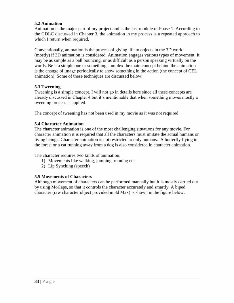
5.5 Movements of Characters
Although movement of characters can be performed manually but it is mostly carried out
by using MoCaps, so that it controls the character accurately and smartly. A biped
character (raw character object provided in 3d Max) is shown in the figure below:
34 | P a g e
Figure 5.13 as provided in 3d max by default
The movement of the character in my project is done through the use of MoCaps.
35 | P a g e
CHAPTER SIX
PROJECT ESTIMATIONS
This chapter deals with the predicted requirements before the starting of the project and
the actual outcomes observed during and at the finalization of the project. The predictions
were mainly based on the logical estimations but differences were experienced at some
level.
What are Estimations?
Predictions made at some level about the future outcomes of any process or the resource
that may be used for the production can be termed as estimates. These estimates may be
in the form of calculated solutions, algorithmic results or purely conceptualized thinking.
Whatever be the case estimates provide a great deal of help to achieve the desired results.
Estimations can be of time duration, processing cost, future problems etc.
My Estimations
When I started the project, certain predictions and estimations were made depending on
the production costs, rendering time, design complexity and expected problems.
6.1 Production Cost
Production costs are the major estimations of costs that are related directly to the
production process. These may include the cost of the software needed to carry out the
project, the hardware purchased. The expenses may also be related to the marketing of
the project etc.
The project of 3D animation is one of the most expensive projects. There are mainly two
reasons of that. First is that the cost of the software related to the processes are very high.
Secondly, to achieve the desired high quality output, special purpose devices are
available in the market as well as high speed machinery is also one of the most important
requirements. A commercial project in 3D may consume thousands of pounds or even
more to get standard outputs.
At the student level, definitely I cannot put up such high budgets, but worked on
alternatives. The required software were mostly available as a free for student purpose.
To balance out the speed difference I used cluster based rendering instead of 3D Graphic
Acceleration Cards. To keep up the speed there was one more consideration that I had to
take under notice i.e. design complexity (It will be discussed in the next topic). Clustered
Rendering is a technique used extensively in the market to substitute the speed gap and
accelerate the production process.
The major expense that was carried out in this project was buying of cables for building
up the cluster. The cost of print outs, posters and DVD’s is also included. Hence a total of
approximately £100 was spent on the project collectively but this rate does not include
the costs of the software as they were on student license and were free to use.

36 | P a g e
6.2 Rendering Time
The rendering time is also major factor in the designing of an animated feature film. The
rendering time depends upon the speed of the available equipment and the nature of
designs. Now a days, Dual Processor Pentium 4 systems and Macintosh systems are
being used extensively in the markets for managing 3D projects. Different Graphic
Accelerator cards are also available to speed up the rendering process. These include
NVDIA, Trident, G-Force and Creative's 3D cards.
According to my estimate the shots were about to take 10 days to complete the rendering
process. This estimation was a bit deviated at the end and was a considerable problem
that I faced.
6.3 Design Complexity
Design Complexity can be defined as the level of meshes or weight of the modeled
objects should be kept low to achieve a high performance of the systems. By weight I
mean that the patch net making up the object should be simple.
It was my initial decision that I have to make the models as simple as possible without
compromising the quality of the objects and to a certain extent I succeeded in achieving
this objective. As you can see in the objects shown in this report in the previous chapter,
most of the objects in the project are based on low polygonal network and the particle
system that I used is also not complex.
6.4 Deviation from the Actual Estimations
I cannot present calculated values or formulated equations for future estimations rather
only logics may be used in my case, due to the nature of the project. The most deviation
appeared in the Rendering Time duration. This mainly happened because certain
restrictions got involved eventually in the project. These include the System Failures,
Time Management and the system's speeds. Due to these reasons, I have excluded two
more footages that I was planning to complete.
6.5 System Resources
The System Resources means the machinery, tools (mostly software in our case) and
manpower which is required to build up any project. Each of these things has their own
importance. Absence of any required resource may end up in some flaw, delay or
difficulty in making the project.
Required Resources
The system level resources that were required for the project for good output include:
6 - 8 Pentium IV Systems minimum 2 GHz
3D Cards / Powerful Video Accelerator and card can also be used
RAM 2 GBs or above
80 - 120 GBs of Hard Disks
Ethernet / Network Connections
I/O Devices
Essential Softwares (Topic 1.5)
Resources Used
The devices that were available to me for the completion of project are:
37 | P a g e
2 Pentium IV & 1 Core i7 Laptop
1GB VGA Card
RAM 4GB maximum
120 GB Hard Drive
Ethernet available
I/O Devices
Essential software
38 | P a g e
CHAPTER SEVEN
EXPANDIBILITY, RECOMMENDATIONS &
CONCLUSIONS
Every project has some margin of enhancement in the future. This chapter deals with the
future enhancements that can be made to the project and recommendations that are
crucial for discussion.
7.1 Expandability
All projects possess great level of expandability but the approaches to various projects
are different. These approaches may depend upon the nature of the project, behavior of
the project or level of perception of the students or the project members.
Expandability is sometimes replaced by flexibility in the project. Flexibility means
adoptive nature of the project that can highly effective in various situations. More flexible
is the software, more the users get attracted to it.
How can my Project Enhance
3D concept provides a greater level of observation and creativity in a person. The
expansion in my project may be carried out in creating some proper story that includes
VFX and motion capturing. My perspective was to create awareness among my juniors
that they must try to work on VFX along with 3d animation and also try motion capturing
thing as our university has got motion capture studio now and they can practice over
there. The enhancement may also be carried out in refining my effects and models to do
much better in the field of Graphics.
7.2 Recommendations
Graphics requires greater level of consistency and observation telling you how you
perceive the world around yourself. To develop in this field the first important
requirement is to increase the observation of oneself. Secondly, Graphics also requires
greater concentration and imaginative thinking. To do better than what I did in the
project, the models must be kept simple and the quality must be kept high using the
meshes. For VFX, the higher amount of RAM is required and bit more particles to
generate realistic effects. To finish the work in lesser time greater number of PC’s will do
a good job.
7.3 Conclusion
The project was an attempt to generate the VFX content that is being widely used in
media industry these days. I have tried to merge the motion capture data with real footage
in order to generate special effects content. The Motion Capture was an entirely new for
me and I have learned in university recently about it. It took a lot of time to get my hands
on controlling MoCaps with 3d models as I didn’t had any prior knowledge or experience
of working with motion capture. Due to lack of resources I couldn’t practiced the motion
capture device but I learned how to use the captured data with our models.
The university has got labs for motion capture but for some reasons we haven’t visited
the lab a single time. I had plans before starting my thesis to record my own MoCaps in

39 | P a g e
the lab so that I can learn to use device as well as the cleaning of motion captured data.
There are several companies on internet which sell their captured MoCaps online so I
bought some MoCaps online which are not expensive but in fact they are quite cheaper.
Using motion capture data with the skeleton and bones system gave me good knowledge
of using MoCaps. I used simple camera without a tripod stand for recording my shots.
There was no proper lighting and all shots were recorded in daylight system. Some shots
were recorded five times in order to achieve what I required for the composition. But
overall process of my thesis gave me experience of how to use camera, lighting, angles in
order to use footage for VFX and also apart from this I learned a lot of major techniques
for polishing the composition part.
40 | P a g e
CHAPTER EIGHT
PROJECT SCHEDULE, REFERENCES & APPENDICES
This section consists of project scheduling, some references and glossary of the terms that
are being used in our report.
Project Schedule
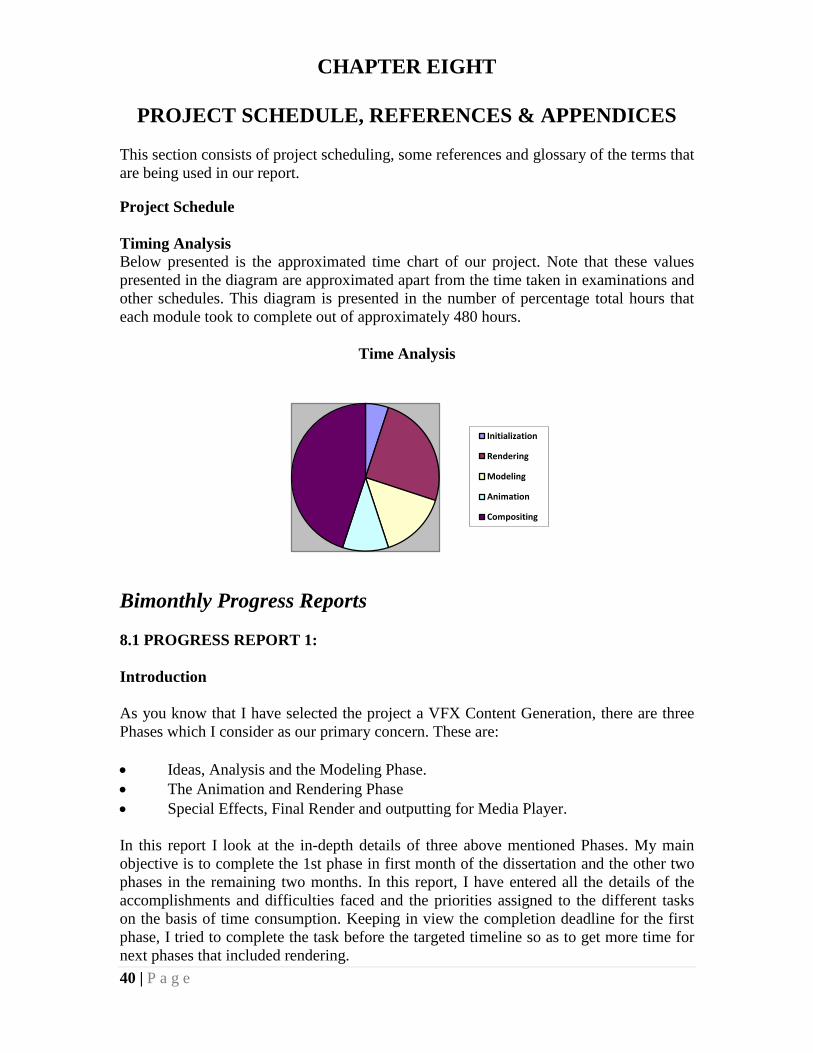
Timing Analysis
Below presented is the approximated time chart of our project. Note that these values
presented in the diagram are approximated apart from the time taken in examinations and
other schedules. This diagram is presented in the number of percentage total hours that
each module took to complete out of approximately 480 hours.
Time Analysis
Bimonthly Progress Reports
8.1 PROGRESS REPORT 1:
Introduction
As you know that I have selected the project a VFX Content Generation, there are three
Phases which I consider as our primary concern. These are:
Ideas, Analysis and the Modeling Phase.
The Animation and Rendering Phase
Special Effects, Final Render and outputting for Media Player.
In this report I look at the in-depth details of three above mentioned Phases. My main
objective is to complete the 1st phase in first month of the dissertation and the other two
phases in the remaining two months. In this report, I have entered all the details of the
accomplishments and difficulties faced and the priorities assigned to the different tasks
on the basis of time consumption. Keeping in view the completion deadline for the first
phase, I tried to complete the task before the targeted timeline so as to get more time for
next phases that included rendering.
Initialization
Rendering
Modeling
Animation
Compositing
41 | P a g e
8.2 Date Wise Distribution
This section of the report gives a detailed layout of the date wise distribution of work. Let
me begin the review as follows:
Brief Description - 8th
June
I completed my some tutorials for VFX and started to search for my footage and photos
in order to start working on them.
TARGETTED AREA --------> Ideas and Storyboard
The main issue of this day I thought was the idea for the footage and settlement of the
storyboard. A rough sketch of the storyboard was made depending on the different ideas
that I got inspired from some of the movies. The requirements were also noted down that
were involved in the completion of the project.
At the end, I end up with some story boards and ideas that I thought I can generate for
special effects. The main problem was to record some clip with green screen and for that,
I thought to search internet for free to use available footages with green screen
background so that I can apply my effect on to it.
Difficulties and problems noticed this day are defined in the Logging Sheet 1 in a more
detailed form.
Brief Description - 22th
June
TARGETTED AREA --------> Cost Estimation
As moving on with the ideas and story boards, I came to this point to estimate my cost in
order to fulfill my requirements. What I needed to buy that I cannot do by myself like
MoCaps, shall I need any 3rd
plug-ins, or I may need to buy license for any product.
When all the data was collected, the first priority was to buy MoCaps as I found that
software are available on student license but not MoCaps.
Difficulties and problems noticed this day are defined in the Logging Sheet 2 in a more
detailed form.
Brief Description – 1st July
TARGETTED AREA --------> Models and Gantt Chart
The main target for this day was an overview of the analysis that was done in previous
days. The analysis reports mainly consisted of the searches which showed a great deal of
help materials, tutorials, online meetings with professional designers to learn about their
working strategies. Some very useful searches were found for the use of MoCaps and its
future developments that are on the way now a days.
After finalizing the analysis phase, practical assignments and tasks were prioritized
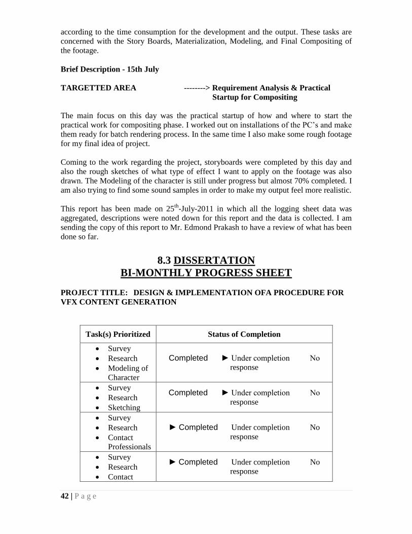
42 | P a g e
according to the time consumption for the development and the output. These tasks are
concerned with the Story Boards, Materialization, Modeling, and Final Compositing of
the footage.
Brief Description - 15th July
TARGETTED AREA --------> Requirement Analysis & Practical
Startup for Compositing
The main focus on this day was the practical startup of how and where to start the
practical work for compositing phase. I worked out on installations of the PC’s and make
them ready for batch rendering process. In the same time I also make some rough footage
for my final idea of project.
Coming to the work regarding the project, storyboards were completed by this day and
also the rough sketches of what type of effect I want to apply on the footage was also
drawn. The Modeling of the character is still under progress but almost 70% completed. I
am also trying to find some sound samples in order to make my output feel more realistic.
This report has been made on 25th
-July-2011 in which all the logging sheet data was
aggregated, descriptions were noted down for this report and the data is collected. I am
sending the copy of this report to Mr. Edmond Prakash to have a review of what has been
done so far.
8.3 DISSERTATION
BI-MONTHLY PROGRESS SHEET
PROJECT TITLE: DESIGN & IMPLEMENTATION OFA PROCEDURE FOR
VFX CONTENT GENERATION
Task(s) Prioritized Status of Completion
Survey
Research
Modeling of
Character
Completed ► Under completion No
response
Survey
Research
Sketching
Completed ► Under completion No
response
Survey
Research
Contact
Professionals
► Completed Under completion No
response
Survey
Research
Contact
► Completed Under completion No
response
43 | P a g e
Professionals
Overall Status of previous Bi-monthly assignment.
Completed ► Under completion No response
Almost completed to 90% of the project task.
Tasks for the next two months till completion:
Character, Rendering, Compositing and Test Animation
It is projected that in the next two months of my project, I will be mainly considering on
the following sections:
Character modeling is one of the toughest jobs considered in 3d modeling.
Character after its modeling, goes to rigging phase and then finally goes for
texturing. As I am using MoCaps for animation so after rigging, I don’t need
manual animation for that. I will apply the pre-captured MoCaps for animation
that will make my work really easy and will save a lot of time.
Rendering: I am rendering alpha-channel shots in order to merge them with my
footage and pictures in Adobe After Effects i.e. my compositing phase. Shadows
are also generated separately which will be then merged with colored outputs and
finally I will apply color correction and final touches to them.
Compositing is the most lengthiest and time consuming phase of my project. As I
want my generated output to be real looking so proper color correction, merging
of models with footage and images, and finally most important merging of special
effects. I am trying to give as much time as I can to this phase as this is the main
target of my project.
Test animation requires a test rendering of the modeled objects. Note that, it is
not the final render. According to my idea, I will try my level best to achieve the
test animation phase so that when the final phase of my project starts, I will be
sufficient with the knowledge of how my character is capable of giving a quality
output and after this I can estimate how much time the final rendering will take.
8.4 DISSERTATION LOGGING SHEET 1
Date: 12
th June, 2011
Name of the project: Design & Implementation of a Procedure For VFX Content
Generation
TASKS TARGETTED:
The main issue targeted was the idea for the footage and settlement of the storyboard.
A rough sketch of the storyboard was made depending on the different ideas from
inspiration of various movies. The requirements were also focused that are involved in
the completion of project.
44 | P a g e
The details of the topic are mentioned earlier in this report.
DISSERTATION LOGGING SHEET 2
Date: 20
th June, 2011
Name of the project: Design & Implementation of a Procedure For VFX Content
Generation
DISSERTATION LOGGING SHEET 3
QUESTIONS/PROBLEMS:
Idea was going out of budget as well as the time which is my primary concern for the
completion of the project in time.
REMEDY / RECOMMENDATIONS:
I thought different approaches to achieve my objectives. I consulted different external
professional designers and searched methods on the internet and so the remedy of this
difficulty was found soon.
TASKS TARGETTED:
I looked over the expenses first as I got a solution for my MoCaps, I need to buy pre-
captured MoCaps from external company. When all the data was collected, I sorted
out everything that matched my idea and was useful for me.
QUESTIONS/PROBLEMS:
1) The major problem that I faced was that the authorized personnel were not
available. My main requirement is to talk and discuss my idea and seek some
guidance from them but due to their jobs, it took some time to reach them and
getting reply back.
2) Another problem that I faced was batch rendering PC’s availability. The PC’s
are not free all the time for use and also they are not at home so I need to visit
the location for rendering that was really far from my place.
REMEDY / RECOMMENDATIONS:
I have got a friend in my home country which helped me in contacting some
professionals and that’s why I was able to contact them within time.
The problem of PC’s was solved when I discussed with my employer and he gave me
permission to use two PC’s of his office after job timings.

45 | P a g e
Date: 5th
July, 2011
Name of the project: Design & Implementation of a Procedure For VFX Content
Generation
DISSERTATION LOGGING SHEET 4
Date: 22
nd July, 2011
Name of the project: Design & Implementation of a Procedure For VFX Content
Generation
TASKS TARGETTED:
I overviewed the analysis reports that were done till the time. The analysis reports
mainly consisted of the data that was downloaded and selected for use. It also
contained some guidelines which were given by professionals in the industry.
QUESTIONS/PROBLEMS:
Practically I faced no such problem in this section. The analysis was a bit time taking
but it was managed to complete somehow.
REMEDY / RECOMMENDATIONS:
After these analysis, I bought an external hard disk of 1TB in order to save my backup
source files, rendered outputs and downloaded MoCaps.
As far as the reports are concerned these analysis reports will continue in the future as
well as they are a nice source of collected data.
TASKS TARGETTED:
I checked the downloaded MoCaps as sometimes it happens that MoCaps contained
some garbage data and it needs to be cleaned. I am unable to clean the data at this
stage so I sorted out the data that is useful for me separately. The rest of MoCaps are
saved for future use if needed somewhere.
QUESTIONS/PROBLEMS:
The problems I faced in MoCaps part was that I was bound to use pre-captured
MoCaps so I cannot apply my own motion that I thought, I can only use the motion
which are available to me on MoCaps. Although our university has got motion capture
device and lab but due to some reasons we are unable to use that. In fact the motion
capture lab, we haven’t visited it a single time.
REMEDY / RECOMMENDATIONS:
I just given some time to MoCaps, and checked them on 3d Max’s biped. The motions
that are useful for me are copied into separate folder whereas the rest are kept saved
somewhere else.

46 | P a g e
PROGRESS REPORT 2:
Introduction:
As was also mentioned in my previous report I have selected the project a MoCaps and
VFX Content Generation, so there are 3 Phases which I considered as my primary
concern.
In this report I, will be discussing the arrangements and the work that was done for the
poster designing and also the compositing of my footage with special effects.
Date Wise Distribution
This section of the report gives a detailed layout of the date wise distribution of work. Let
me begin the review as follows:
Brief Description – 5th
August
Thought of some ideas for poster and worked out on special effects.
TARGETTED AREA --------> Ideas and Storyboard
I am thinking of some ideas for poster designing as I need to define my process that I am
following for my project in pictorial way. First I looked up the guidelines given by
university for designing. I am thinking to draw some vector based layouts in order to
clearly convey my process to the viewers. I am attaching some snapshots from my
artifact and trying to draw a flow chart kind of diagram so that my process could be
clearly shown step by step. In the same time, I am generating rendered outputs for test
rendering. The PC’s for batch rendering are available after a week i.e. from 10th
of
August so I will start heavy batch rendering there. Some workout on character animation
using MoCaps is also in progress.
Brief Description – 30th
August
TARGETTED AREA --------> Printing quotation, Work Analysis
The main thing focused here is the quotations for the printing of the poster and some
other expenses needed on submission. I also looked some other posters related to my
project in order to get an idea of how can I make it delivering and simple. The main
guidelines are provided by the university so there is not enough to work for. I visited
some outlets in my area and I set the cost of approx £100 will be enough for everything
needed.
The second thing that is focused is the work analysis that is being done till date and how
is it proceeding. I am rendering objects with different angles for and also with different
lighting and color correction so that they are merged without coloring errors.
Brief Description – 22nd
September
TARGETTED AREA --------> Professionals Opinion, Finalizing
Outputs
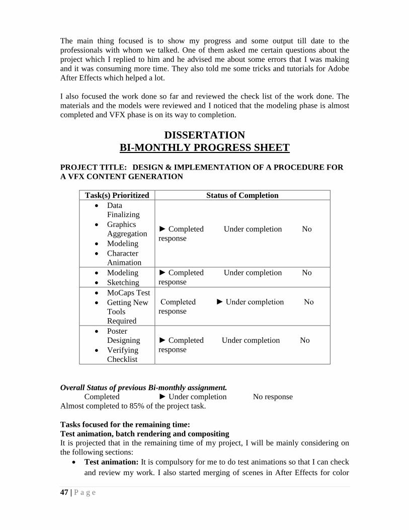
47 | P a g e
The main thing focused is to show my progress and some output till date to the
professionals with whom we talked. One of them asked me certain questions about the
project which I replied to him and he advised me about some errors that I was making
and it was consuming more time. They also told me some tricks and tutorials for Adobe
After Effects which helped a lot.
I also focused the work done so far and reviewed the check list of the work done. The
materials and the models were reviewed and I noticed that the modeling phase is almost
completed and VFX phase is on its way to completion.
DISSERTATION
BI-MONTHLY PROGRESS SHEET
PROJECT TITLE: DESIGN & IMPLEMENTATION OF A PROCEDURE FOR
A VFX CONTENT GENERATION
Task(s) Prioritized Status of Completion
Data
Finalizing
Graphics
Aggregation
Modeling
Character
Animation
► Completed Under completion No
response
Modeling
Sketching
► Completed Under completion No
response
MoCaps Test
Getting New
Tools
Required
Completed ► Under completion No
response
Poster
Designing
Verifying
Checklist
► Completed Under completion No
response
Overall Status of previous Bi-monthly assignment.
Completed ► Under completion No response
Almost completed to 85% of the project task.
Tasks focused for the remaining time:
Test animation, batch rendering and compositing
It is projected that in the remaining time of my project, I will be mainly considering on
the following sections:
Test animation: It is compulsory for me to do test animations so that I can check
and review my work. I also started merging of scenes in After Effects for color

48 | P a g e
correction and VFX. Note that it is not the final render.
Batch rendering: Batch rendering is being done in my office and also at home
with roommate’s PC but the main rendering was done in office.
Compositing: I am merging my footage with the model and trying to apply
realistic effects related to my idea and storyboard. The effects although taking a
lot of time but when it comes to output, I am really getting close to my required
results.
DISSERTATION LOGGING SHEET 5
Date: 15th
August, 2011
Name of the project: Design & Implementation of a Procedure For VFX Content
Generation
FYP MEETING LOGGING SHEET 6
Date: 2
nd September, 2011
Name of the project: Design & Implementation of a Procedure For VFX Content
Generation
TASKS TARGETTED:
I focused on my project designing cost and also look other expenses keeping in mind
that the work should not be delayed during printing quotations. Took some quotation
from the shops nearby and finalized the one that suited me.
QUESTIONS/PROBLEMS:
Practically no problems were faced.
The media analysis was put up for the printing of poster. I collected the media samples
and made a cost analysis report for different types.
TASKS TARGETTED:
I made a feasibility report for my budget and also sorted out the media, ideas and
methods for designing my poster. I was trying to convey my idea and process in a
pictorial view. My poster should tell visually of how and what I have worked on so
that’s why I was really focusing on poster too with my project.
REMEDY / RECOMMENDATIONS:
I tried to make my poster competitive and to show professionalism in my work. It was
also projected that my work will take about 5 weeks to complete finally if I go on with
the same pace.

49 | P a g e
DISSERTATION LOGGING SHEET 7
Date: 22
nd September, 2011
Name of the project: Design & Implementation of a Procedure For VFX Content
Generation
TASKS TARGETTED:
In the first half of the working time I had meeting with some professionals in the
industry. I showed them my work done yet including the model, story boards, idea and
method to achieve that.
Now I am working on compositing phase as this is time consuming task for giving
realistic results. Its rendering doesn’t take much time but working does take.
QUESTIONS/PROBLEMS:
Practically no problems were faced.
REMEDY / RECOMMENDATIONS:
The printing size was given by university i.e. A1. So there is nothing more to worry
about sizing etc.
QUESTIONS/PROBLEMS:
Practically no problems were faced.
REMEDY / RECOMMENDATIONS:
Reviewed my progress in relation with the suggestions given by professionals and
rectified few errors that I noticed. Character modeling and rigging is finalized;
MoCaps are completed; now the merging of scenes with proper color correction and
finalizing the effects is on its way to completion.

50 | P a g e
REFERENCES
1. Richard Rickitt (2000), “Special Effects: The History and Technique”, Billboard
Books
2. Christopher Finch (1989), “Special Effects: Creating Movie Magic”, Abbeville Pr
3. Ron Brinkman (1999), “The Art And Science Of Digital Compositing”, Morgan
Kaufmann
4. Matt Liverman (2004), “The Animator’s Motion Capture Guide: Organizing,
Managing, Editing”, Charles River Media
5. Midori Kitagawa (2008), “MoCap for Artists: Workflow And Techniques For
Motion Capture”, Focal Press
6. Ricardo Tobon (2010), “The MoCap Book: A Practical Guide to the Art of
Motion Capture”, Foris Force
7. Bodo Rosenhahn (2010), “Human Motion: Understanding, Modeling, Capture
and Animation”, Springer
LINKS:
1. http://www.liquiddreamsolutions.com/web5/index.php?option=com_jumi&fileid=
4&Itemid=162 [1]
2. http://sayanimation.com/tag/3d_animation/ [2]
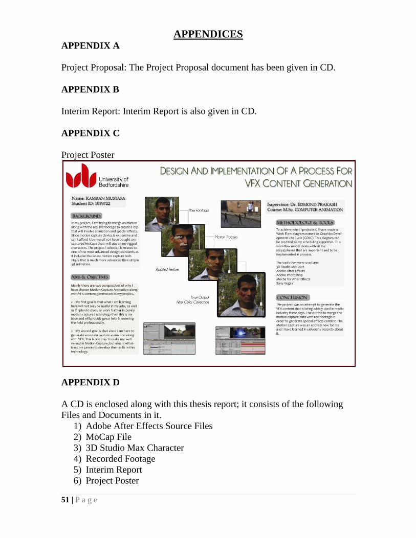
51 | P a g e
APPENDICES APPENDIX A
Project Proposal: The Project Proposal document has been given in CD.
APPENDIX B
Interim Report: Interim Report is also given in CD.
APPENDIX C
Project Poster
APPENDIX D
A CD is enclosed along with this thesis report; it consists of the following
Files and Documents in it.
1) Adobe After Effects Source Files
2) MoCap File
3) 3D Studio Max Character
4) Recorded Footage
5) Interim Report
6) Project Poster