-ilegulators-modules,--and-miscellaneous canal structures
TRANSCRIPT
-ilegulators-Modules,--and-Miscellaneous Canal Structures
13.1. Can~l Regulation -
_13
The water which enters into· the main canal from the river has to be divided into different Branches and Distributaries, in accordance with the relative urgency of demand on different channels. This process of distribution is called 'Regulation'. To distribute water effectively, the discharge has to be adjusted to any desired value. This aim is achieved by means of regulators.
13.2. Canal Regulation Works
The works which are constructed in order to control and regulate discharges, depths, velocities etc. in canals, are known as canal -regulation works. These structures ensure the efficient functioning of a canal irrigation system, by giving full control upon the canals. The important of these structures are :
(i) Canal Falls.
(ii) Canal Regulators (Head Regulator and Cross Regulator).
(iii) Canal Escapes.
(iv) Metering Flumes, etc.
(v) Canal Outlets and Modules.
- Canal fallS nave already bee_ri described in the previous chapter. Now we shall dear with the remaining structures.
CANAL REGULATORS
13.3. Alignment of the off-taking channel
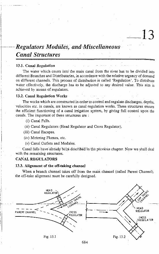
When a branch channel takes off from the main channel (called Parent Channel), the off-take alignment must be carefully designed.
Fig. 13.1 Fig. 13.2
684
REGULATORS MODULES, AND MISCELLANEOUS CANAL STRUCTURES 685
The best ideal alignment is : when the off-taking channel makes zero angle with the parent channel initially and then separates out in a transition, as shown in Fig. 13.1.
The transitions will have to be properly designed, so as to avoid accumulation of silt jetty. As an alternative to the transitions, both the channels should make an angle with the parent channel upstream of the off-take, as shown in Fig. 13.2.
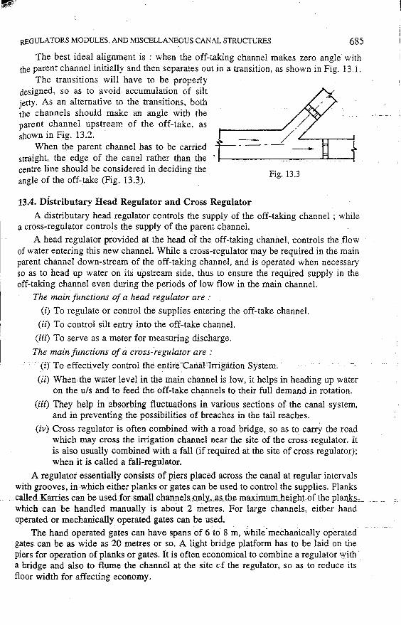
When the parent channel has to be carried straight, the edge of the canal rather than the centre line should be considered in deciding the angle of the off-take (Fig. 13.3).
13.4. Distributary Head Regulator and Cross Regulator
Fig. 13.3
A distributary head regulator controls the supply of the off-taking channel ; while a cross-regulator controls the supply of the parent channel.
A head regulator provided at the head of the off-taking channel, controls the flow of water entering this new channel. While a cross-regulator may be required in the main parent channel down-stream of the off-taking channel, and is operated when necessary so as to head up water on its upstream side, thus to ensure the required supply in the off-taking channel even during the periods of low flow in the main channel.
The main functions of a head regulator are :
(i) To regulate or control the supplies entering the off-take channel.
(ii) To control silt entry into the off-take channel.
(iii) To serve as a meter for measuring discharge.
The main fimctions of a cross-regulator are :
(i) To effectively control the entire Canal Irrigation System.
(ii) When the water level in the main channel is low, it helps in heading up water on the u/s and to feed the off-take channels to their full demand in rotation.
(iii) They help in absorbing fluctuations in various sections of the canal system, and in preventing the possibilities of breaches in the tail reaches.
(iv) Cross regulator is often combined with a road bridge~ so as to carry the road which may cross the irrigation channel near the site of the cross regulator. It is also usually combined with a fall (if required at the site of cross regulator); when it is called a fall-regulator.
A regulator essentially consists of piers placed across the canal at regular intervals with grooves, in which either planks or gates can be used to control the supplies. Planks calledKarries can be used_foumall_channels,Qnly,_as_th_e ma.1'5mJ.J.m_beigbLQfJ_be_Rlfin.ls:s _ which can be handled manually is about 2 metres. For large channels, either hand operated or mechanically operated gates can be used.
The hand operated gates can have spans of 6 to 8 m, while mechanically operated gates. can be as wide as 20 metres or so. A light bridge platform has to be laid on the piers for operation of planks or gates. It is often economical to combine a regulator with a bridge and also to flume the channel at the site c-f the regulator, so as to reduce its floor width for affecting economy.
686 IRRI.GA TION ENGINEERING AND HYDRAULIC STRUCTURES
13.5. Design of Cross Regulator and Distributary Head Regulator .
Crest Levels. The crest of a cross regulator is generally kept at the upstream bed level of the channel. While, the crest level of the distributary head regulator is generally kept 0.3 to 1.0 m higher than the crest level of the cross regulator.
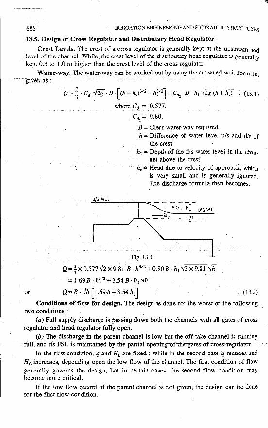
Water-way. The water-way can be worked out by using the drowned weir formula, given as :
Q =j · Cd1 {'ii· B · [<h+hy)312 -h~12]+ Cd
2 • B · h1 .,/2g (h+hv) ... (13.1)
where Cd= 0.577 . . 1 -· . . .
US WL.
. Ci:1z = 0.80.
B = CleM water-way required. h = Difference of water level u/s and d/s of
the crest. h1 = Depth of the dis water level in the chan
nel above the crest. hv = Head due to-~ifOCity of approach, which
is very small and is generally ignored. The discharge formula then becomes.
- - - - - -~-
-9..1 h D/SWL -a h ___ 2 __ 11 __
Fi~. i3.4
Q =~x 0.577;/2x 9.81 B· h312 + 0.80B · h1 .,/2x9.8~ fh = 1.69 B · h~12+ 3.54 B · h1 {ii
or Q = B · fh[ 1.69 h + 3.54 h1] ... (13.2)
Conditions of flow for design. The design is done for the worst of the following two conditions :
(a) Full supply discharge is passing down both the channels with all gates of cross regulator and head regulator fully open.
(b) The discharge in the parent channel is low but the off-take channel is running · fUU;''aird'its-'FSt'is'irrfilritfilri'eu-bytlfo'-jiartial-opening'ortlre-'gates of cross-regulator.
In the first condition, q and HL are fixed ; while in the second case q reduces and HL increases, depending upon the low flow of the channel. The first condition of flow generally governs the design, but in certain cases, the second flow condition may become more critical.
If the low flow record of the parent channel is not given, the design can be done for the first flow condition.
REGULATORS MODULES, AND MISCELLANEOUS CANAL STRUCTURES · 687
Downstream Floor Level or Cistern Leve!. For the above two flow conditions, qandHL are worked out. Then E12 is found from Plate 10.l. The level at which jump
would form, i.e. the level of dis floor, is then given by dis TEL-Ek
Neglecting velocity head, dis TEL= dis FSL :. Level of dis floor =dis FSL - Ek
If the dis floor for the worst condition works out to be higher than the dis bed level of the channel, the floor is provided at the bed level itself.
Length of dis Floor. It is worked out by calculating 5 (y2 - y1). If by chance, this length comes out to be small in comparison to 2/3 of total floor length (worked out by exit gradient considerations, i.e. b =a· d .), then, the length of the dis floor is kept equal to 2/3 of the total floor length.
· Cut-offs are provided as given below : Upstream Cut-off. The minimum depth of u/s cut off below u/s floor level is kept ·
as(;+ 0.6 m} where Yu is the depth of water in th.e channel upstream.
Downstream Cut-off. The minimum depth of dis cut-off below the dis floor level is
kept as. r; + 0.6 m} where yd is the depth of water in the channel downstream.
Total floor Length. The total floor length 'b' is worked out from safe exit gradient considerations, as explained earlier. This total floor length is then suitably distributed · upstream and downstream.
Uplift Pressures and Floor Thicknesses. The thicknesses of the dis floor required, are worked out by working out the uplift pressures by Khosla' s theory. The maximum unbalanced heads at key_ points are worked out for the maximum static head. The pressure at toe of glacis is also worked out for dynamic condition. The floor thicknesses are designed for the worst case, as explained-earlier in-the-design- of-weirs and faUs. A-· nominal thickness of 0.3 to 0.5 m is provided on u/s side.
Protection Works. The protection works are designed for a scour depth (D) equal
to (; + 0.6 m) on the upstream, and equal to r; + 0.6 m) on the downstream. The 'C.C.
blocks' _and 'inverted filter' are provided in a length approximately equal to 1.5 D. The quantity of stone in launching apron is kept as 2.25 D cu. m/metre.
A typical design of such a regulator is illustrated in the example given below :
Example 13.1. Design a cross regulator. and a head regulator for a channel which takes off from the parent channel with the following data :
Discharge of parent channel Discharge of distributary FSL of the parent channel, uls FSL of the parent channel, dis Bed width of parent channel, u/s Bed width of parent channel, dis Depth of water in the parent channel
dis and uls
= 140 cumecs = 15 cumecs = 210.0 m ~ 209.8 m = 52m =46m
= 2.5m
'fr
I
I i
I
,1
' ) !
688
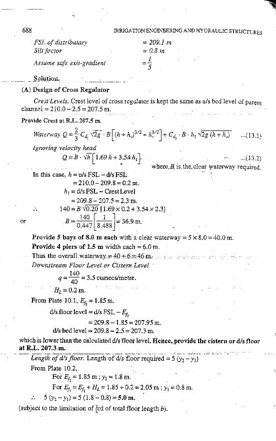
FSL of distributary Silt factor
IRRIGATION ENGIN""EERING AND HYDRAULIC STRUCTURES
== 209.J m = 0.8 m
l -5 Assume safe exit-gradient
.. ______ S9lu,!iQ11. __ ---~-----
(A) Design of C:ross Regulator
Crest Levels. Crest level of cross regulator is kept the same as u/s bed level of parent channel= 210.0- 2.5 = 207.5 m.
Provide Crest at R.L. 207.5 m.
2 ~ l~ 312 v~-1 ~ Waterway Q=3 Cd1
-../2g · B (h+hv) -h~ "'J+ Cdi · B · h1 -Y2g (h+hv) ... (13.l)
ignoring velocity head
... (13.2) Q = B · 01[ 1.69 h + ~.54 h1}
In this case, h = u/s FSL - dis FSL where.8. is LJ.ie_ cle~r \aterway required.
or
= 210.0-209.8 = 0.2 m. h1 =dis FSL - CrestLevel
=209.8 - 207.5 = 2.3 m. 140 = B -J0.20 [ 1.69 x 0.2 + 3.54 x 2.3]
1 40 r i 1 B = 0~447 l 8.488 j = 36·9 m.
Provide 5 bays of 8.0 m each with a clear waterway = 5 x 8.0 = 40.0 m.
Provide 4 piers of 1.5 m width each = 6.0 m. '.fhus-the0'\lernll-_waterwayi=40+o6_;=_46m,, --
Downstream Floor Level or Cistern Level i40
q = 40
= 3.5 cumecs/metre.
HL=0.2m.
From Plate 10.1, E12 = 1.85 m.
dis floor level = dis FSL - E1z
=209.8- l.85=207.95m. dis bed level= 209.8 - 2.5 = 207.3 m.
which is lower than the calculated d/s floor level. Hence, provide the cistern or dis floor at R.L. 207.3 m.
-- ----- . ----· -'-----'-"'-'-----'--'.__ __ - - . - -- - -·----.------------ --- --------- -- ---- -- --Length of dis floor. Length of dis floor required = 5 (y2 - y1)
From Plate 10.2, For E12 = 1.85 m; y2 = 1.8 m.
For E11 = E12 + HL = 1.85 + 0.2 = ~.05 m ; y1 = 0.8 m.
. . 5 ()'2 - y1) = 5 (1.8 - 0.8) = 5.0 m.
(subject to the limitation of trd of total floor length b).
REGULATORS MODULES, AND MISCELLANEOUS CANAL STRUCTURES
Vertical cut-offs
Provide upstream cut-off for a depth
= ~u +0.6 = 235 + 0.6= i.43 m
below the floor, i.e. the level of its bottom
= 207 .5 - 1.43 = 206.07 m. Downstream cutoff Depth of dis cutoff below floor level
Yd 2.5 = 2 _+ o.6 =-T + o.6. = 1.85 m.
Hence, the bottom level of dis cutoff= 207.30- 1.85 = 205.45 m.
Total Floor Length from Exit Gradient Considerations H 1
GE=d·~
689
where H = Maximum static head, which is caused when there is full water on u/s and there is no water on d/s.
or
1 2.7 1 5= l.85. 1C. >ff:
1 1 1.85 n>ff:=sx 2_7 =0.137.
From Plate 11.2, . 1
For n -n::= 0.137, a= 9
H = u/s FSL - dis bed level = 210.0- 207.3 = 2.7 m.
d =Depth of dis cutoff= 1.85 m
GE= .l (given) 5
. . b =ad= 9x1.85 = 16.65m;say17 m. Minimum d/s floor length required
= ~ · b = ~ x 17 = 11.3 m; which is greater than 5.0 m, i.e. 5 (y2 -y1).
He~ce, provide 11.3 m as the dis floor length.
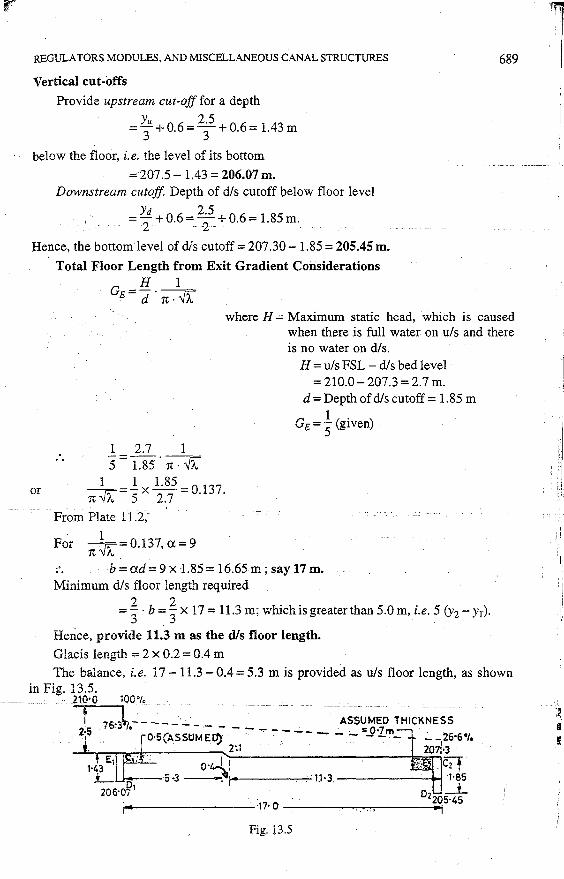
Glacis length = 2 x 0.2 = 0.4 m
The balance, i.e. 17 - 11.3 - 0.4 = 5.3 m is provided as u/s floor length, as shown in Fig. 13.5.
2lO·O 100•1.
t . 76~3~.- - - - -·- ____ ~ .. ···- m ---~~~~MED THl~KNES~ 2]!i . 0·5(ASStJME~ .. ..,.. "."- -- - -:- '- -J)"J...m_ · .:_ _
126·6'1.
2:1 207:•3
Fig. 13.5
I
' :.~ I
•
690 IRRIGATION ENGJNEERING AND HYDRAULIC STRUCTURES
Calculations for Uplift Pressures
Upstream Cut-off d= 1.43 m. b=l7.0m.
l = .4 = I.43 = 0.085
fJ. -b-1-1-.0- . ---- -· From Plate 11.l (a),
<1>£1 = 100%
<l>v = 100%-<l>v= 100%-18.5%= 81.5% I .
<!>c1 = 100% - <l>E = l 00% - 26.5% = 73 .5%
(Assume u/s floor thickness = 0.5 m) Correction to <l>c for floor thickness
I
81.5 - 73.5 O 5 2 gm ( ) = 1.43
x . = . -;o + ve .
:. <l>c (corrected)= 73.5 + 2.8 = 76.3% 1 .
(Note. Correction due to pile interference is small and may be neglected).
Downstream Cut-off
d= l.85m b= 17.0m.
_!_ = .4 = LS5 =0 109 a b 17.0 · ·
From Plate 11.l (a),
<!>E =<l>E=30% 2
<l>v2 = <!>v=21 %
<1>c2 = 0%-·
(Assume dis floor thickness near dis cut off= 0.7 m)
Correction to <l>E due to floor thickness 2
30-21 . = l.S
5 x 0.7 = 3.4% (- ve)
:. <l>E (corrected)= 30% - 3.4% = 26.6% 2
(Note. Correction due to interference of u/s cut off is neglected).
Floor Thicknesses :. Dis Floor
At Toe of Glacis
% pressure at toe of glacis • - . C - 70.3%C-=--26~6% . .... . -- . - . . . .•.. , . . . = 26.6% + 17 x 11.3 "'.' 26.6% + 33.l % = 59.7%
Maximum unbalanced head at toe of glacis due to maximum static head (2. 7 m)
= 59,7% x 2.7=1.61 m. Head due to dynamic action can be taken as
50% (y2 - Yi)+<!> . HL = 50% (1.8'-0.8) + 59.7% x 0.2 = 0.5 + 0.12 = 0.62m < 1.61 m.
REGULATORS MODULE$, AND MISCELLANEOUS CANAL STRUCTURES
Hence, static head governs the thicknesses.
:. Thickness required at toe of glacis
= ~ :~! = 1.3 m; Provide 1.4 m.
At 3 m beyond toe of glacis
% pressure = 26 6o/C 76,3% - 26.6% 8 3
. o+ 17 X •.
~ 26.6% + 243% = 50.9% Maximum unbalanced head
= 50.9% x 2.7= 1.32m. Thickness required
7= ~ :;~ = 1.07 'm; Provide 1.1 m.
At 8 m beyond toe of glacis
% pressure ::.26 6m 76.3% - 26.6% 3 3 .·10+. 17 x.
' = 26.6% + 9.65% = 36.25%
Ma,ximum unbalanced head = 36.25% x 2:7 = 0.98 m.
Thickness required
T ·~.
E . L/'I
a:: Ew
<£> !:i u..' -0 0lL
'-Vl<>IQ
~~~ ~ EO:: Vl
lD . <£> UJ z: W'> 3 r·_;~z
u... E-
~ Oco:S::: 11/l. u 30-o>< I r~ E>-~co
. 6
1: 0
I"'· m
I~ .... C> N u..
..... ....,> f-0 <Co <!> 0::
t.:>
0·98 o 19 P 'd ·o s _t_~~~--1 . = 1.24 = . m; : rov1 e . m I
·'>
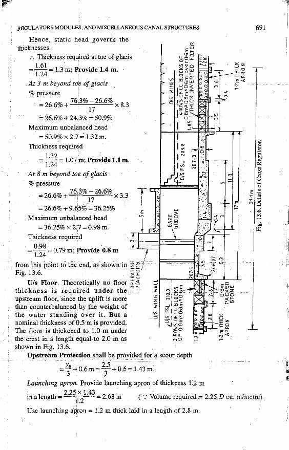
· .. from this point to the end, as: shown in·~·~· .. -:
Fig. 13.6. ~ ~
Gz -0 :c 0:: f- 0. E<(
N ,;..
·v· ~ ~
. ~ ·.
... : ·:::· ~ .. ::::: Vl .ii ...
:-:~:: .· .. !'.': ....
~
.... m .. o v; .. ·..o· .;. 0 .,....
0:: f-
U/s Floor. Theoretically no floor ~ :5 ~i---r-~---r-~1-.,---L---'~
thickness is required under the 0
':
upstream floor, since the uplift is more than counterbalanced by the weight of the water standing over it. But a nominal thickness of 0.5m is provided. The floor is thickened to 1.0 m under the crest in a length equal to 2.0 m as shown in Fig. 13.6. ·
~
<(
3
Vl .. ~
Upstream Protection shall be prc'rvided~ for a scour depth .. Yu i~----·-- -·· . =3+0.6m=T+0.6= 1.43m.
::t
La~nching apron'. Provide launching· apron of thickness 1.2 m
E~w .. '!'.:.:: .. z ouo
<{I-c_l/.l
:>:: u -z: :c 0 f- 0::
E"-"! <(
691
T
._; B o:l
'3 0() Q)
p::
"' "' 8 u ""' 0
E ~ ~ ·~
a)
"" A \Ci r-1
en ~
1
. I h . 2.25.x 1.43 2 68 . (. ,, l . d 2 5 D m.a engt = . 1.2
= . m ·: vo ume reqmre = .2 cu. m/metre)
Use launching apron= 1.2 m thick laid in a length of 2.8 m.
692 IRRIGATION ENGINEERING AND HYDRAULIC STRUCTURES
C.C. Blocks. Lei us provide C.C. blocks of size 0.8 m x 0.8 m x 0.6 m for a length D = 1.5 x 1.43 = 2.2 m. Hence, 3 rows of C.C. blocks of size 0.8 m x 0.8 m x 0.6 m size with 10 cm. jhories filled with bajri, laid over packed stone apron of 0.6 m thickness, in a total length of 2.6 m, .shall be provided as shown in Fig. 13.6.
Downstream Protection shall be provided for a scour depth - -- - -- - --- Yd - -2:5 --- ----- -- -----_ --
D = 2+ 0.6=2+0.6 = l.85m.
Launching apron. Provide a launching apron of thickness equal to 1.2 m.
Length of apron required _
= 2.2; D = 2.25t21.85 = 3.48 m; say 3.6 m.
Provide a launching apron of 1.2 m thickness laid in a length of 3.6 m.
Inverted filter. Length of filter required :== 1.5 x 1.85 = 2. 77 m. Provide 4 rows of C.C. blocks of size 0.8 m x 0.8 m x 0.6 m with 10 cm gaps in
between, laid over an inverted filter of 0.6 m thickness, in a total length of 3.5 m, as shown in Fig. 13.6.
Provide 0.4 m thick and 1.2 m deep toe walls between blocks and apron on u/s as well as on dis.
(B) Design of Distributary Head Regulator
We shall first of all determine a suitable regime section for the distributary, so as to carry the given discharge of 16 cumecs with the given silt factor= 0.8.
From Lacey's Regime Diagrams
Bed width of such a channel = 15.0 m. Depth of water in this channel= 1.5 m. Bed Level of Distributaryy = FSL - Depth= 209.1""'.'.',1.5 = 207.6 m.
Crest Level. The-crest level of the Distributary Head is generally kept 0.3 to 1.0 ill higher than the bed level of the parent channel. Let us keep it 0.6 m higher.
:. Crest Level= 207.5 + 0.6 = 208.1 rn.
Hence keep the crest of Head Regulator at RL 208.1 m. Watenvay. The discharge is given by
Q = B · '\/h [1.69 h + 3.54 hi] i.e. Eq. (13.2)
where h = FSL of parent channel - FSL of Distributary
= 210.0-209.1 =0.9 m. h1 = FSL of Distributary - Crest Level
= 209.1-208.1 m = LOm. - ----Q = 15 cumecs.
B = Clear waterway required .
. . 15 = B · vf0.90 [ 1.69 x 0.9 + 3.54 x vii.o] or 15 =Bx 0.949 [l.521+3.54]
15 or B = 0.949 x 5.061 = 3•12 m.
Which is very small as compared to bed width of distributary, i.e. 15.4 m.
., 1'
I I i
REGULA TORS MODULES, AND MISCELLANEOUS CANAL STRUCTURES
Hence, provide 2 bays of 3.0 m each with 1.0 m thick pier in between.
Overall waterway provided= 6 + l = 7.0 m Clear waterway provided = 6.0 m.
The wing walls shall be expanded with proper divergence, so as to provide the normal width of the channel.
Cistern or dis floor. The discharge intensity q
15 = -- = 2.5 cumecs/metre
6 .. --
HL = u/s FSL - dis FSL
= FSL of parent channei - FSL of Dis tributary = 2 l0.0- 209.l = 0.9 m
From plate 10.1,
E12 = L8 m
Eli =E12 +HL= l.8+0.9=2.7m.
Fro:tn plate 10.2,
For E, =2.7m ;y1 =0.4m J 1 '
For E_12 = 1.8 m ; y2 ::::: 1. 7 :tn.
R.L. of cistern (i.e. d/s floor)
=dis FSL - E12 = 209.1 - 1.8 = 207.3 m.
Length of cistern required
= 5 (yz -y1) = 5 (1. 7 - 0.4)
= 8.0 m (subjected to a minimum of~ b)
Vertical Cutoff Depth of u/s cutoff below floor
Yu 2.5 =3+0.6=3+0.6= 1.43m.
The bottom level of u/s cutoff
= 207.5 - 1.43 = 206.07 m.
The depth of dis cutQff below floor
Yd l.5 =1+0.6=2+0.6=1.35m.
Provide dis cutoff depth = 1.6 m
__ 1.'):i~ bott',)1!1 _of ells cut-off_ _ _______________ _
= 207.3-1.6 =205.7m.
Total Floor Length from Exit Gradient Considerations
dis Maximum static head (H) is caus•;;;G when there is full water on u/s and no water on
H = 210.0- 207.3 = 2.7 m. d =Depth of dis cutoff = 1.6 m.
H 1 GE=d n·K
I'''
I
I
, I
I :I· 11
:I IL
I! ,Ii
' \
694
or
IRRIGATION ENGINEERING AND H:t:DRAULIC STRUCTURES
1 2.7. 1 5=T:f;· 7t'!r
7t ~=J ~ ~:~ =_0.~19_. -
From Plate 11.2, 1 .
For 7t~=0.119;a=l3
b=a · d= 13 x L6=20,8m; say21 m.
Minimum length of dis floor required 2 = 3 x 21 = 14 m. (which is greater than· 8 m.)
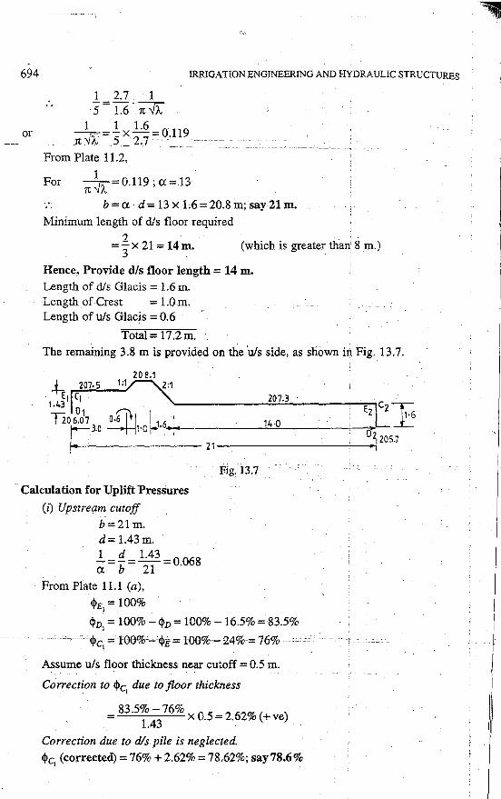
Hence, Provide d/s floor length = 14 m. Length of dis Glacis = 1.6 m. Length of Crest = 1.0 m. Length of u/s Glacis = 0.6
Total= 17.2m. The remaining 3.8 mis provided on the "uts side, as shown id Fig. 13.7.
20 8.1 -h 207-S 1:1
1 • 4~1 CJ 207.3 C
Tio 6~d1 o.6:f j 1 1. 6, I Ez 2 ~
: . 10 1.0 J--1· .'1'"- 14.0 L
02 205.7 ~~~~~~~~~21~~~~~~~~~.,.----i
Calculation for lJplift Pressures
(i) Upstream cutoff
b=2l m. d= 1.43m.
*=~= 12~3 =0.068
From Plate 11.l (a),
<l>E = 100% I
<l>D1 = 100% - <l>D = 100% - 16.5% = 83.5%
·_-_ <l>c-='l00%·-<1>e-=100%-14%-=76% -·-··c --- - ·· I
Assume u/s floor thickness near cutoff = 0.5 m.
Correction to <l>c1
due to floor thickness
= 835% - 76% 0 5 = 2 62~ ( ) 1.43
x . . v +ve
Correction due to dis pile is neglected.
<l>c1
(corrected)=76% + 2.62% = 78.62%; say78.6%
~ I
i
REGULATORS MODULES, AND MISCELLANEOUS CANAL STRUCTURES
(ii) Downstream cutoff
b=21.0m. d= 1.6 m. 1 d 1.6 a.=1;= 21.0 =0.076.
From Plate 1 U (a),
'i>E2 = <l>E = 25.5%
- <j>J:j =<l>D= 17;5% 2
<!>c2 =0%.
Assume dis floor thickness near cutoff= 0.8 m.
Correction to <l>E due to floor thickness 2
=25.5%-17.5% 08=40~(-) 1.6 x . . o ve.
Correction due to dis pile is neglected
<l>E (corrected)= 25.5%- 4.0% = 21.5% 2
Floor Thickness
At toe of dis Glacis
. . 78.6% - 21.5% %age pressure= 21.5% +
21 x 14
= 21.5% + 38.1% = 59.6%
Maximum unbalanced head due to static head
· ·=s9.6%x 2.1·;;,· Ls·8-in.
Head due to dynamic action can be taken
= 50% (y2 -y1) + ¢ · HL
= 50% (1.7 - 0.4) + 59.6% x 0.9 = 0.65 + 0.54 = 1.19 m; which is less than 1.58 m .
. Hence, static head governs the floor thicknesses. Flcior thickness required at toe of glacis
= !:~! = 1.28 m; Provide 1.4 m.
At 3 m beyond toe of dis glacis
-----~%agepressure'-,;;'2r.s%·+-18 ·6%;:2IS% xTf-"'--'''"--'"~-cccc:. .:::.::: ... ::: ...... --------··
= 21.5% + 29.9% = 51.4% Unbalanced head= 51.4% x 2.7 = J ,::;9 m.
Thickness reqd. = ~ :;: = 1.12 m; Provide 1.2 m.
At 6 m ·beyond toe of dis Glacis
%age pressure = 21.5% + 78·6% ~ 21.
5% x 8 ='.21.5% + 21.8% = 43.3%
695
-------r:
OP~RATING PLATFORM
, Jfl.IO~f. Afl.RAN"LM£.NT MAV OR M"Y MO_T 6£. Pll0YID£.O
u/s w1wG w•~L 211· & ! II 1 ~~£?""·~·"'""-'trm.-----------~·----J; t 111111 rtr-- """'~!:'-!forn
i' U/5 F !> L 210·0
1£.R
~..____ __ --,--~-
llOW5 Ot: ,.C. Bl.0(.;K~ OF 0·9l"lllll.O (Ul\.ll0·6W\. 01/Llt
~(~1.0 St<>Mf. OJ: 0 6ir Hf\C.K
~ ~~::~"''°'·-·:.• . ... _., . .... .
' ,.
G•\~E. Glloov&
Lt. Vf.L) - _fel_s ~~ ~09-.L -
20T·~ . -~;--T-·-_--,~-: .. ·~ ~-._ • • . ..
'-•. I·~ , . ..,.. _.l__..t-~-~ ~:t· ,_,r--
' ~o-· .... ;· •' ~ 1,.
,O .. 'M · o·.\"' o.!Qw. . H 2·& .... 4 ~'"'' +--~~,. .......... ~ J·OM • 30M 4 ·~--~"' -fr---- 3.N M
i
:i Fig. 13
1
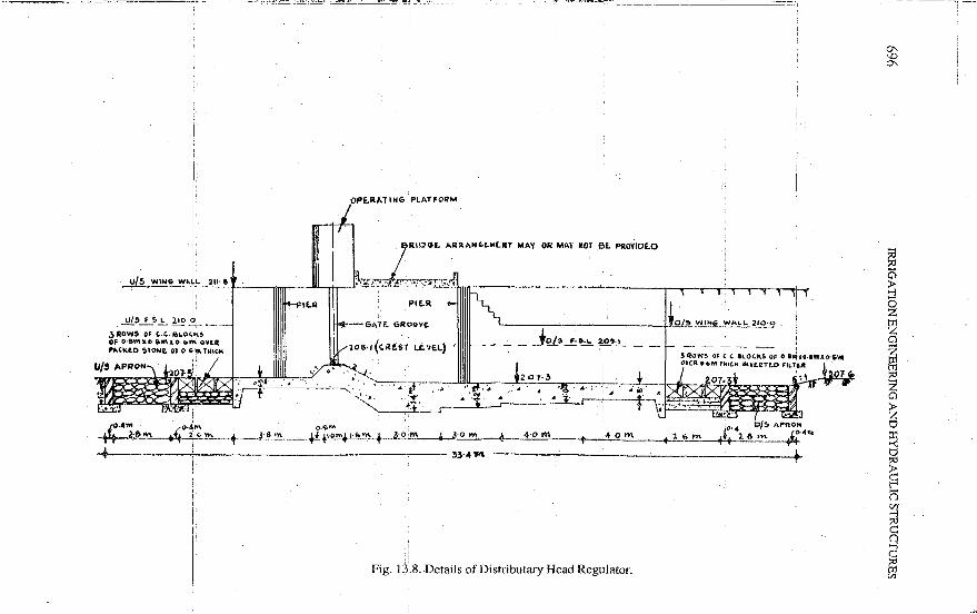
.8. Details of Distributary Head Regulator.
~~/5 WIH6 ~ALL 210·0
to·4 0/:, APRON
~"'..,.. +•+ 2.6 '"' t-:4 .. + -----+
°' \()
°'
~ ::l 0 z r.g Cl z ~ z Cl ~ z 0 ::r:
~ ~ p () Cll -l ::<:! c:: () -l c:: 51
,,
REGULATORS MODULES, AND MISCELLANEOUS CANAL STRUCTURES 697
Unbalanced head= 43.3% x 2.7 = 1.17 m
Thickness reqd. = ~:~~ = 0.945 m. Provide 1 m.
At I 0 m beyond tow of dis Glacis . 78.6% - 21.5%
%age pressure= 21.5% + 21
x 4 = 21.5% + 10.9%= 32.4%
Unbalanced head= 32.4% x 2.7 = 0.875m.
Thickness reqd. = ~·~;: = 0.705 m; Provide 0.8 m upto the end, as shown in Fig. 13.8.
Vis Floor. Provide a nominal thickness of 0.5 m under the u/s floor and extend it under the crest and then join it to the bottom of d/s glacis, as shown in Fig. 13.8.
U/s Protection. Same as provided in the upstream of Cross Regulator. Dis Protection. The d/s protection shall be provided for a scour depth (D)
Yd 1.5 =2:" + 0.6 =2+ 0.6= 1.35m.
Launching apron. Provide 1.2 m thick launching stone in a
1 (1 h- 2.25 x 1.35 en0 t - 1.2
2.54 m; say 2.6 m.
Inverted filter. The length of filter reqd. = I.SD= 1.5 x 1.35 = 2.03 m.
Provide 3 rows of C.C. blocks of 0.8 m x 0.6 m size with 10 cm jhories filled with bajri, laid over 0.6 thick inverted filter.
The details are shown in Fig. 13.8. CANAL ESCAPES
As the name implies, an escape is a side channel constructed to remove surplus water from an irrigation channel (main canal, branch canal, or distributary, etc.) into a natural drain. The water in the irrigation channel may become surplu'> due to some mistake;::. or-diffieulty_-in regulation at. the head;-or _ due,to-excessive.r~ii:ifalL in upper_. reaches. Sometimes, the cultivators may find that the demand of water is over and may close their outlets suddenly, In such circumstances, the canal supplies shall become· surplus, and this excess may overflow the banks unless escaped.
Nq doubt, in all such circumstances, the suppiies shall be reduced or stopped from the hea'd works, but the effect of this reduction is felt only after a certain time. Therefore, in order to avoid damage, some immediate action is required, and this is achieved by means of an 'Escape', generally called a 'surplus water escape'.
, The importance of such an escape is realised more, in case, a breach occurs iri a channel. If a breach occurs, immediate information is sent to the head, so as to close down the channel supplies. But the water already contained in the channel from the head to the breach site, will cause wide spread damage if allowed to pass through the breach. In such circumstances, the escape existing on upstream of the breach is opened and most of the water is allowed to escape. Hence, it can be stated that escapes are the safety valves-vfcandls and must be.provided at regular intervakdepending: upowthdmportance of the channel and availability of a suitable drainage for the disposal of the escaped water. The minimum capacity of the escape is generally kept as half of the channel capacity at the point of the escape.
13.6. Types of Canal Escapes
Such an escape may be of the following two types :
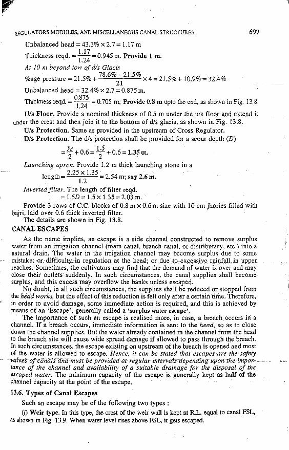
(i) Weir type. In this type, the crest of the weir wall is kept at R.L. equal to canal FSL, as shown in Fig. 13.9. When water level rises above FSL, it gets es~aped.

'A
1900
I
0 00 lO I
.. o L Q
BED WIDTH (8)
2000
I I
2H+80mm= 1780
1900
. I BOTTOri1 1 PLAN OF A P. M.
l I ·1 MASONRY TO BE BROKEN
WHILE RECHANGING THE . DISCHARGING CAPACITY.
_JI . . -4--1.25 F. S.L. g I 1 -[HEAD ABOVE IL
.~---'-'--- -·----·-· .. --· - - - -- ------- ·-·
----------~.-_ .. -t- -~rl·.-,··r-o THE CREST= 1.25 . 1 f!jl ··.SUCH THAT- ->--' lO, . '° I'- Hs J:i.y = O.~ a w : I r:o w Cli o . I r-rl---'-----1-
u.: - -:- ~ j;...L" ~ c:._
2060 1780
i 1250
1230
H
if _JI I
1520
0 0 r<l
,f'
I!) N '<1'
Cil
4680 760
0 Q
0 c;:;
o_j ~ A
Q ())
Q
ALL DIMEtJSJONS_ AHE.- -IN r:nm~· . . -.. -· ·- --~ ... ~~-~.:::-:---=-=-----.-~ - ·---=- -· -------~-- --
SCALE= I: 25
75 TH. PRECAST R.C.C. SLAB l /, II'> 1- ;<· - ·I'~ /,
-~ 0 ~ ---+
--C~.:.g. .. '-'----~-~
BRICK EDGE 115 TH. C.C. 150 TH. I: 4: 8
SECT ION AT A-A . Ffg.13·20
SECTION AT B-8
698 IRRIGATION ENGINEERING AND HYDRAULIC STRUCTURES
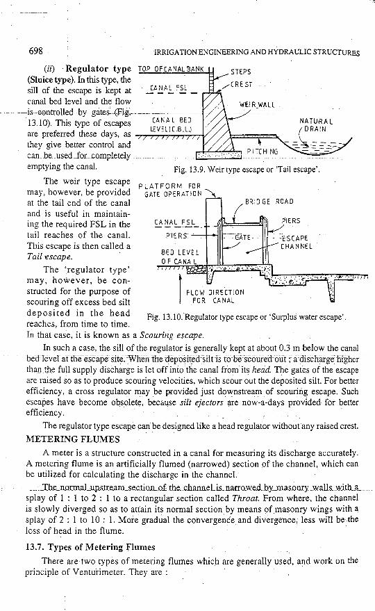
(ii) Regulator type TOP OF CANAL BANK
(Sluice type). In this type, the sill of the escape is kept at canal bed level and the flow
CANAL FSL
- --- ---is GentrolleEi by -gates- (Fig.-=--- -13.10). This type of escapes CANAL BED
" d h d LEVEL(C.B.L.) are pre1e1Te t ese ays, as _,_~.,....,..~,...,...,...,...,-v
they give better control and c.an __ be._used_foL completely emptying the canal. Fig. 13.9. Weir type escape or 'Tail escape'.
The weir type escape p LAT FORM FOR may, however, be provided GATE OPERATION~ at the tail end of the canal and is useful in maintaining the required FSL in the tail reaches of the canal. This escape is then called a Tail -escape.
CANAL F SL
P'I ER S --+-o..,11
BRIDGE ROAD
PIERS
ESCAPE CHANNEL
The 'regulator type' may, however, be constructed for the purpose of scouring off excess bed silt deposited in the head reaches, from time to time.
Fig. 13.l 0. Regulator type escape or 'Surplus water escape'.
In that case, it is known as a Scouring escape.
In such a case, the sill of the regulator is generally kept at about 0.3 m below the canal becllever artlie-escape= site:-·Wli.e'I1The ueposifod·siltis tQ-5e:scoriredour; a:=aischarge'firgner than the full supply discharge is let off into the canal from its head. The gates of the escape are raised so as to produce scouring velocities, which scour out the deposited silt. For better efficiency, a cross regulator may be provided just downstream of scouring escape. Such escapes have become obsolete, because silt ejectors are now-a-days providecl for better efficiency.
The regulator type escape can be designed like a head regulator withoutany raised crest.
METERING FLUMES
A meter is a structure constructed in a canal for measuring its discharge accurately. A metering flume is an artificially flumed (narrowed) section of the channel, which can be utilized for calculating the discharge in the channel.
___ ._Tb~...:n_or:maLup_s_tr_e.am_se.c.tioJLof the __ chann.eLis_narro_we_d _ _hy_mas.onry _walls_ with __ a_ splay of 1 : 1 to 2 : 1 to a rectangular section called Throat. From where, the channel is slowly diverged so as to attain its normal section by means of masonry wings with a splay of 2 : 1 to 10 : l. More gradual the convergence and divergence, less will be the loss of head in the flume.
13.7. Types of Metering Flumes
There are two types of metering flumes which are generally used, and work on the principle of Venturimeter. They are :
REGULATORS MODULES, AND MISCELLANEOUS CANAL STRUCTURES
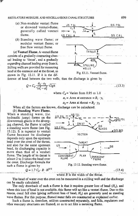
(a) Non-modular venturi flume or drowned venturi-flume, generally called venturi flume.
(b) Standing wave flume; or modular venturi flume; or free flow venturi flume.
(a) Venturi Flume. A venturi flume consists of a gradually contracting chan- -nel leading to 'throat', and a gradually expanding channel leading away from it. Stilling wells are provided for measuring head at the entrance and at the throat, as shown in Fig. 13.11. If h is the dif
_U'"'"'/S~F S"'r"L...._---=- _ J _ Vl h
77-- Y1 ~-U/S LB.L J l//IJ/J I
1
Fig. 13.11. Venturi flume.
ference of head between the two wells, then the discharge is given by
ti1 . a2 . r;;-;-Q = C{J • I 2 2 -v2gh
'W1 -a2
where Cd= Varies from 0.95 to 1.0
a1 =Area at entrance= B1 • y1
a2 = Area at throat ~ B2 · Y2
When all the factors are known, discharge can be calculated. (b) Standing Wave Flume. ·
699
D/S F SL
D/S C. B. L II///}/>;
... (13.3)
When a standing wave, (i.e. hydraulic jump) forms on the downstream glacis in the diverg-
UIS TEL · UIS FSL -- ]: - . L - - --f-1---::::... :-- - - -- -H..,.2o7s FSL
_ing channel; the flume is called a standing wave flume (see Fig. 13.12). It is superior to venturi flume because its discharge depends only upon the upstream head over the crest of the throat, and also for the same upstream head, its discharging capacity is more than that of a venturi flume. The length of its throat is atleast 2 to 3 times the head over the crest. Discharge formula for such a flume is given by
Q = 1.7 Cd· B · H312
- -~ HL_ CREst'' JO,, - _ l --_J_ '. DtS
U/S C.B.L. / .~ _,..G,LA Cl S ~ .... ---""f""'o1~s_a __ rn
SECTION
1 ............... THR9AT ,---1
1 1 / ' _01s r 1 I . I
U/S -CONVERGENT
FLUME PLAN
·Fig. 13.12. Standing wave flume.
... (13.4) ____ . __ . ____ - ---'------· -----· -- -· -- --· ---~h~i:tirr;'Wi~~i<lthoYtfi~l:liroai·:-'----'--·_c __ . c-.c __ ;:
The head of water over the crest can be measured in a stilling well and the discharge can be easily calculated.
The only drawback of such a flume is that it requires greater loss of head (HJ, and where this Joss of head is not available, this flume will act like a venturi flume. Due to this reason, canal fall sites (giving sufficient loss of head, HJ are generally used as standing wave flumes. For this purpose, flumed meter falls are constructed as explained earlier.
Such a flume is, therefore, seldom constructed separately, and falls, regulators and other masonry structures are flumed, so as to act like a metering flume.
l
700 IRRIGATION ENGIN'EERiNG AND HYDRAULIC STRUCTURES
CANAL OUTLETS OR MODULES
A canal outlet or a module is a small structure built at the head of the watercourse so as to connect it with a minor or a distributary channel.
The control and maintemance of the entire network of canals upto the module falls - ~i:inder the-jurisdicfron-of-the-State-Government;-and beyon-d -the module, the entire
working of the water courses or field channels is taken care of by the cultivators themselves. The module is thus a connecting link between the Government and the cultivators. These outlets play a very prominent role in controlling the flow of water to different areas, so as to effect an equitable distribution of available water in accordance with the needs of the whole area.
Hence, an outlet should be such that it fits well to the decided principles of water distribution.
Moreover, it should be simple, cheaper, efficient and easy to handle. The. design of the outlet is, therefore, of prime importance in efficient and effective management of canal irrigation system. The requirements of a good module are listed below :
13.8. Requirements of a Good Module
(1) The module should fit well to the decided principles of water distribution. For example, if the supply is to be fixed in accordance with the cultivable area commanded by the outlet, the outlet must be able to pass a constant and a fixed discharge. Similarly, if the supply is to be regulated in accordance with the area irrigated in the past year, the capacity of the outlet should be capable of being changed from year to year.
(2) The module should be simple, so that it can be easily constructed or fabricated by local masons or technicians.
(3) It should work: efficiently with a small working head. ( 4) The outlet should be cheaper, since they are required in large numbers. (5) It should be sufficiently strong with no moving parts, thus avoiding periodic
maintenance. _____ _ ___________ ---·- _____ -·----· __ (6) The outlet should be such as to avoid_interference_by cultivators, thus preventing
undue tapping of water by cultivators. In other words, any- interference by the local people should be made difficult and easily detectable.
(7) It should draw its fair share of silt.
13.9. Types of Outlets (Modules)
The various available types of outlets can be classified into three classes : (i) Non-modular outlets are those through which the discharge depends upon the
difference of head b0tween the distributary and the water-course. The discharge through such a module, therefore, varies widely with either a change in the water level of the distributary or that of the water-course. The common examples of this type of outlets are : (z) open sluice, and (ii) drowned pipe outlet.
(ii) Semi-modules or Flexible modules are those through which the discharge is indepenaent'of-the-waterle-vel ofthe water-course but depends only upon the water level of the distributary so long as a minimum working head is available. The discharge through such an outlet will, therefore, increase with a rise in the distributary water surface level and vice versa. The common examples of this type of modules are : pipe outlet, venturi flume, open flume and orifice semi-module.
(iii) Rigid modules or Modular outlets are those through which the discharge is constant and fixed within limits, irrespective of the fluctuations of the water levels of either the distributary or of the water course or of both. Gibb's module is a common example of such a module.
··~

REGULATORS MODULES, AND MISCELLANEOUS CANAL STRUCTURES
13.10. Criteria for Judging the Performance of Modules
701
The behaviour and functioning of a module can be judged by the following important terms and definitions :
Flexibility. Flexibility is defined as the ratio of the rate of change of discharge of the outlet to the rate[ ~f 5ha]nge of discharge of the distributary channel.
Thus F=1
~ ... (13:5)
where F = Flexibility of the outlet q = Discharge-passing through the outlet Q = Discharge in the distributary channel.
Now, if His the head acting on the outlet, the discharge through the outlet (q) may be expressed as
or
q = C. H"' ... ( 13.6) where C and m are constants depending upon the type of outlet
Similarly, the discharge passing down the distributary channel may be expressed as Q = K. yn ... (13.7)
where Kand n are constants and y is the depth of water in the distributary.
Differentiating equations (13.6) and (13.7), we get m I · dq=C.m·H - dH
dQ = K · n · yn-:, 1 dy Dividing equation (13.8) with (13.6), we get
!!:!1_= C. m · Hm-I dH m dH q C·H"' H
Similarly,
dQ _ K · n · t- 1 dy !!:. dy Q- K·yn y
Hence, the flexibility, !!:!1_ m
HdH m dH m · dH F=_g_=--=-.X.-=-.1..-
dQ !!:. dy H n dy n H dy Q y
F=m .1... dH n H dy
... (13.8)
... (13.9)
... (13.10)
... (13.11)
... (13.12)
But since a change in the water depth of the distributary (dy) would result in an equal change-in_the head wqrlcing 9.11 the outlet (dH)_, we have
dy=dH. Substituting in equation (13.12), we get
Flexibility = F = m · 1.. n H ... (13.13)
Proportionality. The outlet is said to be proportional when the rate of change of outlet discharge equals the rate of change of channel discharge. In other words, the outlet is 'proportional' when 'flexibility' equals unity. Hence for a proportional outlet, we get
,, 'l)''lm
i
702
or
IRRI.GA TION ENGINEERING AND HYDRAULIC STRUCTURES
F=m·L=l n H
H m outlet index y n channel index
... (13.14)
Setting. The_ ratio Ely, i.e. the ratio of the depth ofthe sill kvei of the outlet below the FSL of the distributary, to the full supply depth of the distributary, is known as setting. Thus, for a proportional outlet
Hly, i.e. 'outlet setting' should be made. outlet index
- ch8.nriel index· For a wide trapezoidal channel, the discharge is proportional to y513
. Therefore, for such channels
n=513
Hence, the channel index is generally 5/3. The discharge through an orifice type outlet is
proportional to W; and thus for such an out~~t, jn~=~ l1l_=_t _ . H m 112
:. Settmg =-=-=-=0.3 y n 513
Hence, for such a combination of an orifice type outlet and a trapezoidal channel, the setting must be equal to 0.3. In other words, a pipe or orifice type outlet shall be proportional, if the outlet is fixed or set at 0.3 times the depth below the water surface.
Similarly, for a weir type outlet, m = 312 (·.·the discharge is proportional to H312). Hence, the setting for a combination of a weir type outlet and a trapezoidal channel
m 312 =-;:;-= 513 =0.9
Hence, for the weir type outlet to be proportional, the outlet should be set at 0.9 times the depth below the water surface. · · -_--
Hypercproportional outlet. An outlet is known to be hyper-proportional if its flexibility is greater than unity.
or
Thus F = m . L > 1 n H
H m -<-y n
or
or
m H ->n y
S . m
ettmg<- n
Hence, the outlet will be hyper-proportio'nal, if the numerical value of its setting (Hly) is less than min. In other words, the outlet is hyper-proportional if set higher (i.e. head acting on the outlet, H, is less than what is required for proportionality).
Sub-proportional outlet. An outlet is known to be sub-proportional if its flexibility is less than unity. Thus -··-'-·-----'-· ----p-;;;m-.x:_ ·<'-i-'--- -''-'---~~------· -._:_-.m:~_H.__,.._-_~--- - '--
0;ccc:-.- ''~---11-;'-,f,,.'-'~=---'
nH n y y n
Hence, the outlet will be sub-proportional, if the numerical value of its setting (Hly) is more than min. In other words, the outlet is sub-proportional if set lower (i.e. His more than what is required for proportionality).
Sensitivity. Sensitivity is defined as the ratio of the rate of change of discharge through the outlet to the rate of change of water level of the distributary, referred to the normal depth of the .channel. For rigid modules, the discharge is fixed and hence the sensitivity is zero.
"'l""'l''H •I
REGULATORS MODULES, AND MISCELLANEOUS CANAL STRUCTURES 703
For flexible modules, where the discharge through the outlet is independent of the water level of the watercourse and depends only upon the water level of the distributary, a gauge can be fixed and calibrated so as to indicate its reading G = 0 when q = 0. Thus
S . . . ' - s - [E!i.!.!L] . ens1t1Vlty - , - dG/y .. (13.15)
I I
Relation between Sensitivity and Flexibility. We know that · - ---
Flexibility =F=[:3;~] i.e. Eq. (13.5)
dQ n But Q =--y dy . _ . .... i.e .. Eq,_(13,11) ___ ..
Equation (13 .. 5t then becomes
F _ dql q ]- _!_ [Efi] - (n/y) dy - II dy/y
But since, dG = dy we get F = _!_ · S. n
or I S::::~_:F j ... (13.16)
If ri = ~' for wide trapezoidal channels, then, S = (5/3) F. j .
It is also evident that :
(i) Greater is the variation in the discharge of an outlet for a given rise or fall in water surface level of the distributary, the larger is the sensitivity of the outlet.
(ii) The sensitivity of a non-flexible module is zero.
13.11. Certain other Important Definitions Connected with Modules
Minimum modular head. The minimum difference between the upstream and downstream water levels, which is required to be maintained so as to enable the module to pass the designed discharge is known as minimum modular head or minimum modular loss.
Efficiency of an outlet. It may be defined as the ratio of the head recovered to th~ l1ead put in. Lesser is the head required for fiiiictioning ofiliecoiitTff; illore efficientthe outlet will be. Efficiency is a measure of the conservation of head by the outlet.
Drowning Ratio. It is the ratio of the depth of water level over crest on the downstream of the module to the depth of water level over crest on the upstream of :11
module. In case of a weir type outlet, the efficiency is the same as the drowning ratio. Modular limit and modular range. The modular limits are the extreme values of
any one or more variables, beyond which an outlet becomes incapable of acting as a module or semi-module. The range between the lowest and the highest limiting values of various such factors is known as modular range.
13.12. Types of non-Modular Outlets
A non-modular outlet may be in the form of a rectangular opening or open sluice, or a simple submerged pipe. Pipe outlet (when submerged) is a very simple type of a non~modular outl~t and is_~_x.!_~n~y-~!~u~~il_in,~~~~~}_n_dia_.= __ ==
13.12.1. Open Sluice. An open sluice (Fig. 13.13), like a bridge opening, is a rectangular pucca opening created across the bank of the distributary, by raising two abutments at 2.5 to 3 m apart and with a horizontal pucca floor. The width B of the opening and height H of the opening are computed to pass the given discharge, by using the appropriate discharge formula.
The sill level of the outlet (i.e. the sill level of the pucca floor) is kept somewh~t above the DBL of the distributary, as shown in Fig. 13.'13. For maximum silt draw, however, the height of water level in distributary above sill level, i.e, H, has to be kept equal to FSD of distributary, y.
.. : .. ''·.~
704 IRRIGA TIONENGINEERING AND HYDRAULIC STRUCTURES
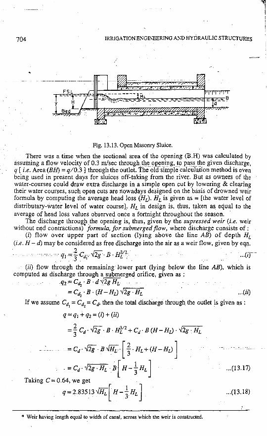
Fig. 13.13. Open Masonry Sluice.
There was a time when the sectional area of the opening (B.H) was calculated by assuming a flow velocity of 0.3 m'sec through the 02~ning, _t() pas_s t!le given discharge, q [i.e. Area (BH) = q/0.3] through the outlet. The old simple calculation method is even being used in present days for sluices off-taking from the river. But as owners of the water-courses could draw extra discharge in a simple open cut by lowering & clearing their water courses, such open cuts are nowadays designed on the basis of drowned weir formula by computing the average head loss (HJ. HL is given as = [the water level of distributary-water level of water course].. HL in design is, thus, taken as equal to the average of head loss values observed once a fortnight throughout the season.
The discharge through the opening is, thus, given by the supressed weir (i.e. weir without end contractions)• formula, for submerged flow, where discharge consists of:
(i) flow over upper part of section (lying above the line AB) of depth HL (i.e. H - d) may be considered as free discharge into the air as a weir flow, given by eqn,
2 . . r;:;- . 312- . . qi ~3-Cd/· -v2g . B. HL ' . . . .. ur
(ii) flow through the remaining lower part (lying below the line AB), which is computed as discharge through a submerged orifice, given as ;
. q2=Cdz·B·d.Y2gHL . . .
= Cd2
• B · (H - HL) ..J.2g · HL ... (ii)
If we assume Cd1 = Cd
2 =Cd, then the total discharge through the outlet is given as :
q =qi -i- q2 = (i) +(ii)
=~Cd· {'ii· B · Hf2 + Cr B (H-HJ · ..J.2g · HL
-=-Cd ·.J2i· B..J.HZ· [ ~ · HL +(H-HL)]
=Cr ..J.2g · HL · B[ H-t HL J ... (13.17)
Taking C = 0.64, we get
q=2.83513ffi[ H-±HL] ... (13.18)
r * Weir having length equal to width of canal, across which the weir is constructed.
l
REGULATORS MODULES, AND MISCELLANEOUS CANAL STRUCTURES
Flexibility of an open sluice is given as
705
=F= m xL=_I_xL=l2'.:. n H 513 H 5 H
... (13.19)
and setting Hly for proportionality= min= 3/5 = 0.6.
Hence for an open sluice to be proportional, the pucca floor should be provided in such a way as to give H = 0.6y ; or the sill level of floor be provided at 0.4 y above the DBL of canal.
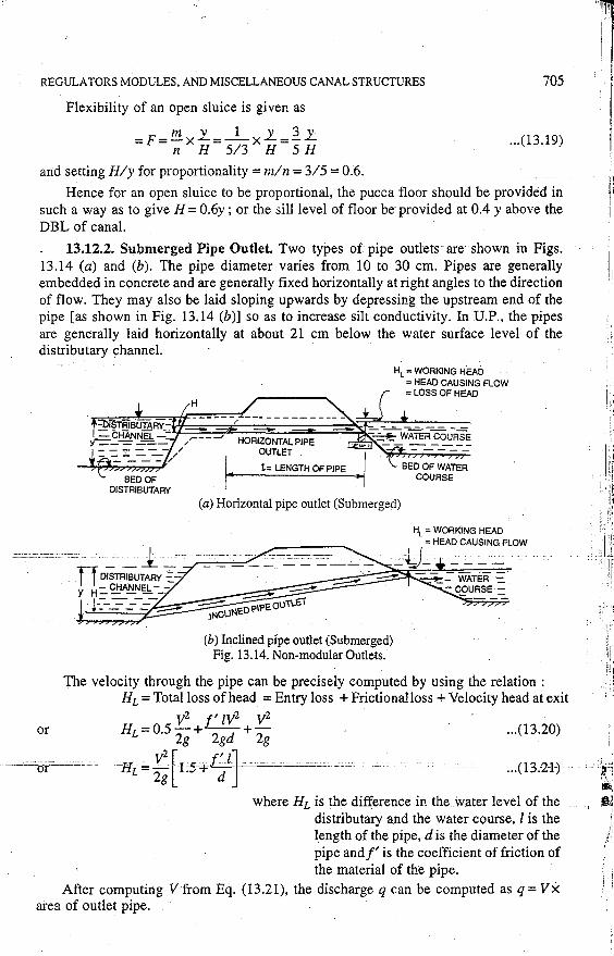
13.12.2. Submerged Pipe Outlet. Two types of pipe outlets are shown in Figs. 13.14 (a) and (b). The pipe diameter varies from 10 to 30 cm. Pipes are generally embedded in concrete and are generally fixed horizontally at right angles to the direction of flow. They may also be laid sloping upwards by depressing the upstream end of the pipe [as shown in Fig. 13.14 (b)] so as to increase silt conductivity. In U.P., the pipes are generally laid horizontally at about 21 cm below the water surface level of the distributary channel. ·
or
HL = WORKING HEAD = HEAD CAUSING FLOW
( = LOSS OF HEAD
_i_J * - +=---=--:.=...-== --= - :_ ~ WATER COURSE
OUTLET
l= LENGTH OF PIPE ~I
(a) Horizontal pipe outlet (Submerged)
(b) Inclined pipe outlet (Submerged) Fig. 13.14. Non-modular Outlets.
The velocity through the pipe can be precisely computed by using the relation : HL =Total loss of head =Entry loss + Frictionalloss +Velocity head at exit
_ v2 f' zv2 v2
HL-0.5 2g + 2gd + 2g ... (13.20)
--<Jr------ -Hi= r;-[1 :S-+if J--°'=~---·.:..:c.:c. ... (13.-21]
where HL is the difference in the water level of the distributary a.nd the water course, l is the length of the pipe, dis the diameter of the pipe and f' is the coefficient of friction of the material of the pipe.
After computing V from Eq. (13.21), the discharge q can be computed as q = Vx area of outlet pipe.
,'
i
'~r·: :-:\:I ~ ~ I ! .i:i
1,
"
706 IRRIGATION ENGINEERING AND HYDRAULIC STRUCTURES
The discharge, however, for all practical purposes, may be easily computed by using the simple relation :
q =Cd· A· "12gHL ... (13.22)
where q = Discharge through the outlet • _____________ _ _-_ __ _ CJ_=::._ _C_oefficient of discharge for the pipe outlet.
Its average value, determined at CWPRS poona is 0.73, although it depends upon the length & size of the pipe, besides on the pipe material.
A = Area of the pipe HL = Difierencc of head between the FSL of dis
tributary and FSL of wmer course, usually called worJ<-jng head of irrigation outlet.
It becomes evident from equation ( 13.22), that the discharge through the outlet can be increased by increasing HL or by lowering th;; bed of the watercourse. Hence, for a certain water level in the distributary, the water entering high fields shall be less and that entering the lower fields shall be more ; consequently equitable distritiution of water becomes difficult, as the owners of high fields are put to a di~advantagc in drawc;l of tfo:ir shcu·e.
Although, such outlets can. work eve:: with ,.,.,. y sma!! available hea+;, and silt conduction is also quite good due to di srurban<1..: at :he mtrance, they m<1y not be preferred as they do not ensure equitable distriburim, l~f water.
Pipe outlets ;.ire more in vogue in South India, where glazed earthenware pipe lengths, 0.6m long, are used to build up the barrel. Against the usual convention of sockets facing against the flow, the pipes- here.- -are usually laid in the reverse direction, otherwise the head (front) socket will become a bellmouth at entry of discharge from the distributary, making the measurement of diameter difficult and unreliable. The; spigot of the pipes are b"nce kept at the upstream ends.
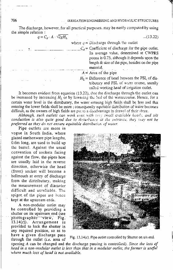
A non-modular outlet may
I be controlled by providing a shutter on its .upstre~m_ end (~ee
1
-- -----irh-o-i-ogrnp"hlc· ·v1ew,---P-fg~-
13.14(c)). Arrangement is provided to lock the shutter in
l i I
any required pos1t1on, so as to 1
have a given discharge pass . . '1!
th h th tl t ( . f Fig. 13.l 4(c). Pipe outlet controlled by Shutter on u/s end. !_I roug e ou e 1.e. area o · opening A can be changed and the discharge passing is controlled). Since the loss of head in a non-modular outlet is less than that in a modular outlet, the former is useful where much loss of head is not available.
REGULATORS MODULES, AND MISCELLANEOUS CANAL STRUCTURES 707
Flexible modules (semi modules) and rigid modules are preferred to non-modular outlets, so as to ensure more equitable distribution of water in the watercourses, irrespective of their being at high or low levels. However, such outlets can work as modular outlets, only within certain limits of water level in the dis tributary and the water course. The range over which eac\1 module works as modular outlet, is called its working range; or range of modularity. Also certain minimum difference of water levels on two sides of each module should always be there to ensure its modularity (i.e. its working as modular outlet). This minimum difference of levels is called minimum modular head or minimum loss of head of the modular outlet.
Example ·13.1. Design mz irrigation outlet for the following data : FSQ of outlet ·· = 50lit/sec. ··· · ·· -
FSL in distibutary on u/s side of outlet = 200.00 m. FSL in water course on dis side of outlet = 199.92 m. FSD in distributary on u/s side of outlet = 1.05 m. Solution. Available head across the outlet
= FSL ofDistributary - FSL of water course = 200.00-199.92= 0.08 m.
Since the available head is very small, a non-modular outlet (such as a submerged
pipe outlet) will have to be provided ['.'The very small head of0.08 m clearly indicates that the dis water level will definitely be above the opening on that side.]
The discharge in such a submerged pipe outlet is given by Eq. (13.22) as:
Q =Cd· A · .../2g HL
where Q = 50 lit/sec= 0.05 cumec. A = Area of pipe
HL = working head or Loss of head between .. u/s and d/s.
= 0.08m Cd ::o. 73. for subinergeo flow.
Putting these values in the above Eqn. we get . 0.05 = 0.73 A · .Y2 x 9.81 x 0.08 or A= 0.055 m2
If a pipe of dia d is used, then
~ d2 = 0.055 m2 or d=0.264m.
Hence, use a pipe of dia, say 30 cm. The R.L. of the bed of the distributary
= 200.00 - 1.05 = 198.95 m. The pipe top can be fixed at about 22 cm below the FSL of the distributary. In other
· words; the pine· can· be laid-horizontally with,its. invert level-(or.si111e:vel) =200.00-0.22-0.30= 199.48m ·
i.e. at 199.48- 198.95 = o.~3 m above the bed of the distributary.
13.13. Types of Semi-Modules or Flexible Outlets
The common types of semi-modules are :
(i) Pipe outlet discharging freely into the air.
(ii) Venturi-flume outlet or Kennedy's Gauge outlet.
(iii) Open flume outlet.
I! !j
· :~.H1 ;~:
1:1 1:1 ,,I
.111
Jr I•' I I' f' i
708 IRRIGATION ENGINEERING AND HYDRAULIC STRUCTURES
(iv) Adjustable orifice semi-module.
These outlets are discussed below in details :
13.13.1. Free Pipe Outlet. Pipe outlet discharging freely into the atmosphere is the simplest and the oldest type of a flexible outlet. The discharge through such an outlet wiH
· depen-d onlyupun-thewater level of the distributary, and will be independent of the water level of the water-course so long as the pipe is discharging freely. Silt conduction for such an outlet is quite good and efficiency is high. But a freely falling jet outlet can be provided only at a few places where sufficient level difference between the distributary and water-course is available. The discharge can be easily computed by using the equation.
Q =Cd· A· ..J2g Ho ... (13.23)
where Cd is coefficient of discharge = 0.62 for average condition of free over fall.
H0 = Head on u/s side measured from FSL of distributary up to the centre of pipe outlet.
A = Area of cross-section' of pipe Example 13.2. Design a pipe outlet for the following data : Full supply discharge at the head of water course = 90 lit/sec FSL in distributary = 205.00 m. FSL in water course = 204.00 m.
Solution
Available head across the outlet = FSL of distributary - FSL of water course =205.00-204.00= 1 m.
This available head of 1 m is sufficient enough to make the pipe outlet discharge freely into the water course, as the dis end of the pipe can be fixed below the water level of the water course, thus making ita semi-module. -· - ... ---=---
The discharge through such an outlet is given as : Q = Cd ·A ..J2g Ho
where Cd=. 0.62 for free pipe outlet.
H0 = Head on upstream side above the centre line of pipe.
Q = 9.0 lit/see= 0.09 cumec. Assuming the dia of the pipe as 25 cm, we have
0.09= 0.62[ ~ x (0.25)2] ..J2 x 9.81 H0
= 0.62 x 0.049 x 4.43 -{ff -'-'1'Ft; ~-o-.e>s7'ID.''' -" ,._.,,:c _ _::_:_-'-'-.:.::.C. --·-·--··-·-·-··-·· ---
H0 =0.44m
:. R.L. of the centre of outlet pipe = 205.00- 0.44 = 204.56 m.
R.L. of invert of outlet_ pipe (i.e.· sill level)
= 204.56 -0
;5
= 204.43 m > FSL of water course i.e. 204.00 m.
REGULATORS MODULES, AND MISCELLANEOUS CANAL STRUCTURES 709
Hence, a pipe of 25 cm dia can be laid horizontally with its bottom or sill level at RL 204.43 m, and it will be discharging freely as a semi-module. Ans.
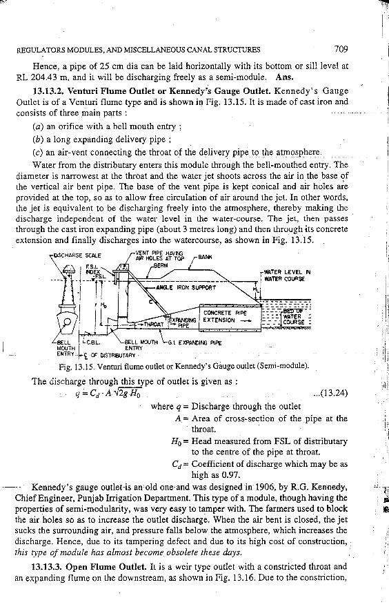
13.13.2. Venturi Flume Outlet or Kennedy's Gauge Outlet. Kennedy's Gauge Outlet is of a Venturi flume type and is shown in Fig. 13.15. It is made of cast iron and consists of three main parts :
(a) an orifice with a bell mouth entry ;
(b) a long expanding delivery pipe ;
(c) an air-vent connecting the throat of the delivery pipe to the atmosphere.
Water from the distributary enters this module through the bell-mouthed entry. The diameter is narrowest at the throat and the water jet shoots across the air in the base of the vertical air bent pipe. The base of the vent pipe is kept conical and air holes are provided at the top, so as to allow free circulation of air around the jet. In other words, the jet is equivalent to be discharging freely into the atmosphere, thereby making the discharge independent of the water level in the water-course. The jet, then passes through the cast iron expanding pipe (about 3 metres long) and then through its concrete extension and finally discharges into the watercourse, as shown in Fig. 13.15.
BANK
WATER L£VEL IN WATER COUl'a$E
--- --- ---------P=CONC=R=E::cTE=P,"'PE=~- ~ ~ ~_:BE~r:0i3:
: : : :. WA'l'ER : EXTENSION ::: .::: _- ~ COURSE :
BELL • C.aL. BELL MOUTH G.I. EXPANDING PIPE MOUTH I E.NTR'r' ENTRY 'rt Of' DISTR8JTARY
Fig. 13.15. Venturi flume outlet or Kennedy's Gauge outlet (Semi~module).
The discharge through this type of outlet is given as : q =Cd ·A ..J2g H0 ... (13.24)
where q = Discharge through the outlet A = Area of cross-section of the pipe at the
throat. H0 = Head measured from FSL of distributary
to the centre of the pipe at throat.
Cd= Coefficient of discharge which may be as high as 0.97.
Kennedy's gauge outlet-is an"old one'and was designed in 1906, by R.G. Kennedy, Chief Engineer, Punjab Irrigation Department. This type of a module, though having the properties of semi-modularity, was very easy to tamper with. The farmers used to block the air holes so as to increase the outlet discharge. When the air bent is closed, the jet sucks the surrounding air, and pressure falls below the atmosphere, which increases the discharge. Hence, due to its tampering defect and due to its high ccist of construction,
1
this type of module has almost become obsolete these days. .
13.13.3. Open Flume Outlet. It is a weir type outlet with a constricted throat and an expanding flume on the downstream, as shown in Fig. 13.16. Due to the constriction,
~.ill
I
710 IRRIGATION ENGINEERING AND HYDRAULIC STRUCTURES
a super-critical velocity is ensured in the throat and thereby allowing the formation of a jump in the expanding flume. The formation of hydraulic jump makes the _outlet discharge independent of the water level in the water-course ; thus making it a semimodule. There are many types of such an outlet.
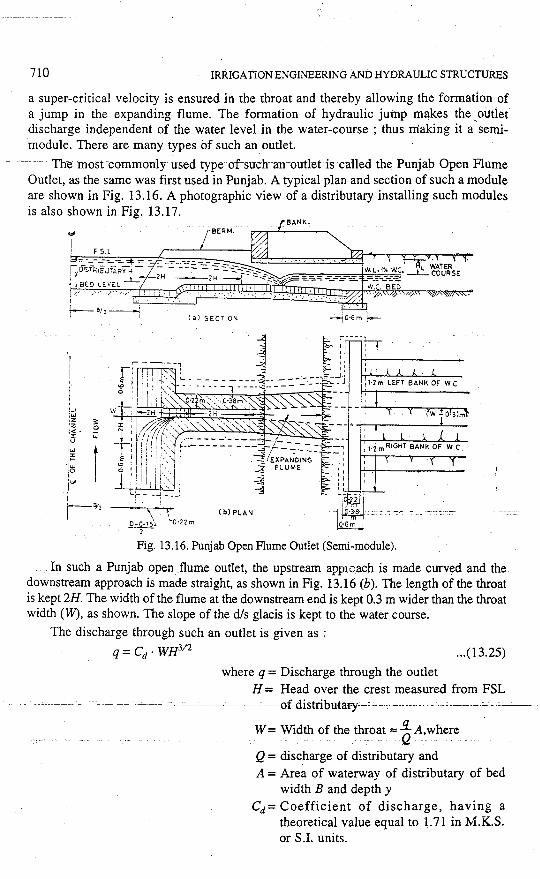
-- ·- The most-commonly-used type of-such-an-outlet is called the Punjab Open Flume Outlet, as the same was first used in Punjab. A typical plan and section of such a module are shown in Fig. 13.16. A photographic view of a distributary installing such modules is also shown in Fig. 13.17.
BERM.
(aJ SECTION --Jo·6m \.-
!-1 \'i !~ 3: 'Z g '"". r u. f'._1 [W
r ·<=
·1:s i"" I lo/'
Fig. 13.16. Punjab Open Flume Outlet (Semi-module) .
. In such a Punjab open flume outlet, the upstream app1oach is made curved and the downstream approach is made straight, as shown in Fig. 13.16 (b). The length of the throat is kept 2H. The width of the flume at the downstream end is kept 0.3 m wider than the throat width (W), as shown. The slope of the d/s glacis is kept to the water course.
The discharge through such an outlet is given as :
q =Cd· WH312 .•• (13.25)
where q = Discharge through the outlet H = Head over the crest measured from FSL
----·----- -- ~---------- · ····· ------of-distributary--: ····: --------- --__ , _______ :... __ . ----
W =Width of the throat==~ A, where .
Q = discharge of distributary and A = Area of waterway of distributary of bed
width B and depth y Cd= Coefficient of discharge, having a
theoretical value equal to 1.71 in M.K.S. or S.I. units.
REGULATORS MODULES. AND MISCELLANEOUS CANAL STRUCTURES 711
Due to the various losses, the actual value of Cd is less than 1.71, and depends upon the width of the throat as shown in Tabie 13.1.
Table 13.l ----·----------------------
Throot width in m~',.es (W)
0.06 to 0.089
0.0\l to 0.119
Ovcr0.12
Vaiue of Cd
1.60
1.64
1.66
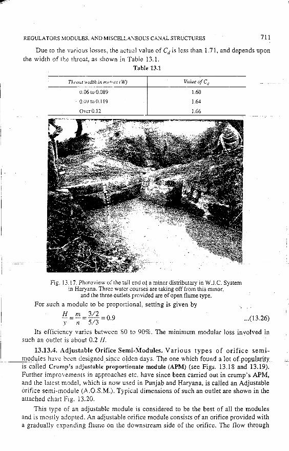
Fig. 13. ! 7. Photoview of the tail end o~ a minor distributary in W.J.C. System in Haryana. Three water courses are taking off from this minor,
and the three outlets provided are of open flume type.
For such a module to be proportional, setting is given by
H = m = ~11: = 0.9 ... (13.26) y n ), j
Its efficiency varies bii!tween 80 to 90%. The minimum modular loss involved in such an outlet is about 0.2 H.
13.13.4. Adjustable Orifice Semi-Modules. Various types of orifice semi----=.@2~ules have been designed since olden days. The one which found a lot of1::mpulari1y ..
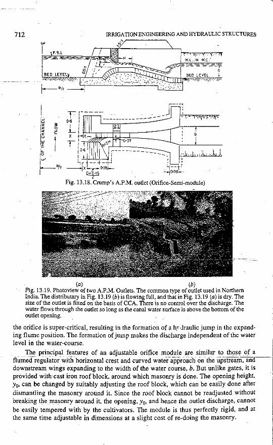
is called Crump's adjustable proportionate module (APM) (see Figs. 13.18 and 13.19). Further improvements in approaches etc, have since been carried out in crump's APM, and the latest model, which is now used in Punjab and Haryana, is calied an Adjustable orifice semi-module (A.O.S.M.). Typical dimensions of such an outlet are shown in the attached chart Fig. 13.20.
This type of an adjustable module is considered to be the best of all the modules and is mostly adopted. An adjustable orifice module consists of an orifice provided with a gradually expanding flume on the downstream side of the orifice. The flow through
712 IRRIGATION ENGINEERING AND HYDRAULIC STRUCTURES
(a) (b) Fig. 13.19. Photoview of two A.P.M. Outlets. The common type of outlet used in Northern India. The distributary in Fig. 13.19 (b) is flowing full, and that in Fig. 13.19 (a) is dry. The size of the outlet is fixed on the basis of CCA. There is no control over the discharge. The water flows through the outlet so long as the canal water surface is above the bottom of the outlet opening.
the orifice is super-critical, resulting in the formation of a h;·· ;Jraulic jump in the expanding flume position. The formation of jump makes the discharge independent of the water level in the water-course.
The principal features of an adjustable orifice module are similar to those of a - flumed regufator.wiiii horizontal crest and curvecfwater.approach on the upstream, ano __ _
downstream wings expanding to the width of the water course, b. But unlike gates, it is provided with cast iron roof block, around which masonry is done. The opening height, y0, can be changed by suitably adjusting the roof block, which can be easily done after dismantiing the masonry around it. Since the roof block cannot be readjusted without breaking the masonry around it, the opening, y0, and hence the outlet discharge, cannot be easily tempered with by the cultivators. The module is thus perfectly rigid, and at the same time adjustable in dimensions at a slight cost of re-doing the masonry.
REGULATORS MODULES, AND MISCELLANEOUS CANAL STRUCTURES
The discharge through such an outlet is given by the formula :
713
' q = Cd · (W · y0) · .Y2g Hs ... (13.27)
where q = Discharge through the outlet
W = Width of the throat
q = 4.04 · W · Yo fH';
Yo= Height of the orifice opening (smallest)
= generally kept · 1.5 to 2 times the width (W) of the opening.
H5 = Head measured from the upstream water level in the distributary to the lowest point of the roof block.
Cd= Coefficient of discharge, whose value varies between 0.8 to 1.05 for throat width (W) varying between 0.06 to 0.3 m. It may be safely taken for normal throat . width (of the order of 0.12 m or so) as 0.91, in which case the above formula reduces to
... (13.28)
This type of adjustable modules are provided in eight different standard widths = 0.06, 0.075, 0.10, 0.12, 0.15, 0.19, 0.24 and 0.3 metres.
The minimum modular hedd loss involved in such a module is given by the formula w
HL = 0.82H5 -2 ... (13.29)
Originally, when this module had a setting (i.e. H/y) of 6/10, it aimed at exact proportionality and, therefore, used to be called A.P.M. (Adjustable Proportional
_,-,-Module). But experience showed that the channels using such modules-silted very badly, and hence proportionality was sacrifi_ced to enable the outlet to carry higher silt charge by increasing the setting to 8/10. Since then, the outlet is known at A.O.S.M. (Adjustable Orifice Semi-module). . ..
A few rules which are of use fo fixing the dimensions of the latest model of AOSM have been indicated in the Fig. 13.20 itself.
Advantages of this type of outlet are : . (i) The adjustment can be made by raising or lowering the roof blocks at low costs
: by dismantling the masonry in which the roof bolts are fixed. (ii) Any undue tampering of roof blocks by the cultivators can be easily detected,
as it requires the breaking of the visible masonry key. (iii) It is simple and cheaper. _
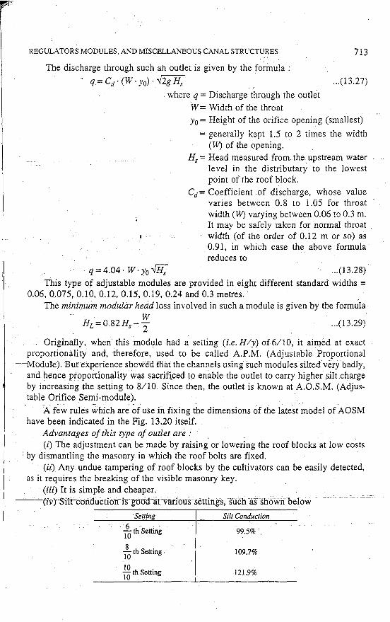
--· ·_-(iv)'-S'ilrcon'du-ctfo·n-1·scgoo'd·a.t ·variounenirtgs, stich ·a.s--showri befow ··
·settin 6 . IO th Setting
180
th Setting
IO . IO th Settmg
Silt Conduction
99.5%
109.7%
121.9%
714 IRRIGATION ENGINEERING AND HYDRAULIC STRUCTURES
13.14. Types of Rigid Mod~les
There are a few types of rigid modules which have no moving parts, such as :
(i) Gibb's module ;
------------ -Eii} Khanna~s--r-igid-module--;-and--------_-_ c---~----
(iii) Foote module.
Out of all these modules, Gibb's module is the most important and widely used. It is described below :
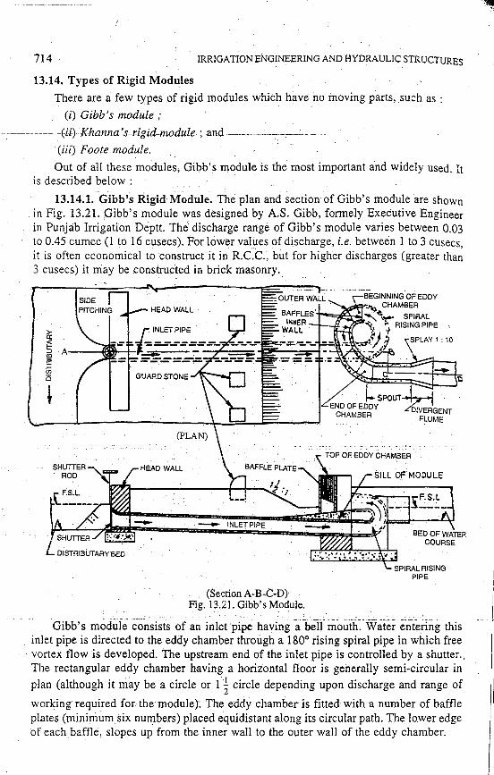
13.14.1. Gibb's Rigid Module. The plan and section of Gibb's module are shown in Fig. 13.21. Gibb's modu1e was designed by AS. Gibb, formely Executive Engineer in Punjab Irrigation Deptt. The discharge range of Gibb's module varies between 0.03 to 0.45 cumec ( 1 to 16 cusecs). For lower values of discharge, i.e. between l to 3 cusecs, it is often economical to construct it in R.C.C., but for higher discharges (greater than 3 cusecs) it iriay be constructed in brick masonry.,
(Section A-B-C-D) Fig. B.21. Gibb's Module.
Gibb's -module-consrsis of an inlet pipe havin£a-belf m-outh~-Water entering this inlet pipe is directed to the eddy chamber through a 180° rising spiral pipe in which free vortex flow is developed. The upstream end of the inlet pipe is controlled by a shutter., The rectangular eddy chamber having a horizontal floor is generally semi-circular in
plan (although it rriay be a circle or 1--~ circle depending upon discharge and range of
working required for the module}. The eddy chamber is fitted with a number of baffle plates (minimum six numbers) placed equidistant along its circular path. The lower edge of each baffle, sIOpes up from the inner wall to the outer wall of the eddy chamber.
REGULATORS MODULES, AND MISCELLANEOUS CANAL STRUCTURES 715
The free vortex flow generated in the eddy chamber ensures, that, velocity x radius= constant, for all filaments. Thus, the water at the outer wall of the chamber having greater radius will have lesser velocity, resulting in a rise of water level there. Hence, the water surface level in the eddy chamber wiil slope down from the outer wall towards the inner wall. The baffle plates inserted in the eddy chamber, sloping up towards the outer wall, at required heights above the sill of the module, will help in preventing any excess amount of discharge likely to pass through the module. If the head causing flow increases, water banks up at the outer wall and impinges against the baffles, imparting a.n upward rotational flow to the water, whieh spins round in the compartment between two successive baffles, and finally drops on the oncoming stream of water ; thus dissipating excess energy; This helps in keeping the discharge constant for a wide range of variations in the head. The number of baffles coming into the action depends upon the variation in the head, as more and more baffles come into action with more and more discharge. The device thus maintains a constant discharge.
The discharge through the Gibb's module is given by Gibb's formula as :
_ r;:;-( )1.5 [m2 - 1 · 1 m2
- IJ q = r2 • -vLg y1 +·h2 . ~loge m + m lo& m - 2~3 - - ... (13.30)
where r1 = radius of inner semi-circle
r2 = radius of outer semi-circle
m=!i r1
y1 = Depth of water at inner circumference
h2 = Head at outer circumference.
Gibb's formula given above, is based on free vortex flow and h0lds good only for his standard design in which
h1 I · m=2and-=-
D 7 where D is the difference of level measured from
. the minimum. water level in the parent channel to the floor of eddy chamber.
MISCELLANEOUS CANAL S.TRUCTURES
13.15. Cattle Crossings
Whenever canals are to be crossed from one bank to another, certain arrangements must be made for suitable crossings. Normally, bridges are provided across the canals at suitable key points, so as to permit the movement of traffic, cattle, and human beings, etc. across the canals. However, in remote village areas where no major movement is
--·invelved,:·certain arrangements-are-made s0-thaHhe-cattle, buH0c~carts-,etc~ can-swim· across the canals. Such crossings are called cattle crossings~· or cart crossings.
For canals, carrying smaller water depths, of the order of 0.75 m or so, a ramp is provided for the entry, and another ramp opposite to the entry ramp is provided for the exit. The cattle or cart moves from one bank on the pitched ramp, comes on the bottom of canal within the water, and goes across by walking over the exit ramp. _.
But for larger canals, having water depth greater than 1.2 m or so, the ~attle will have to swim as they cannot straightaway walk down from one bank to another (via
716 IRRIGATION ENGINEERING AND HYDRAULIC STRUCTURES
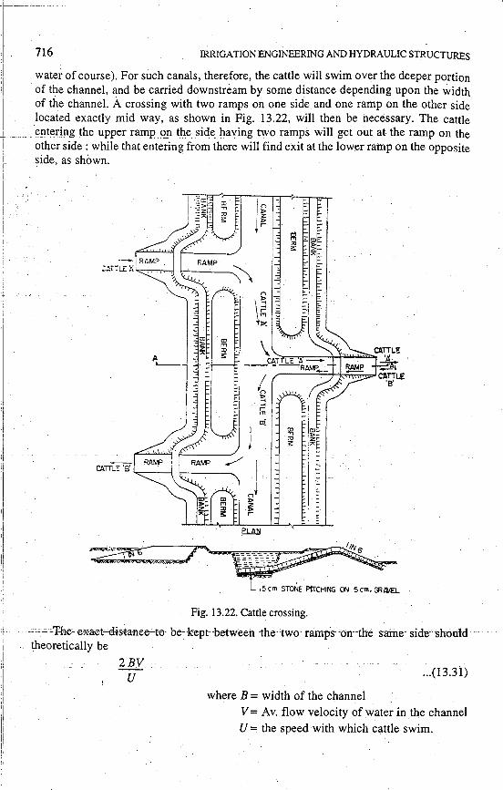
water of course). For such canals, therefore, the cattle will swim over the deeper portion of the channel, and be carried downstream by some distance depending upon the width of the channel. A crossing with two ramps on one side and one ramp on the other side located exactly mid way, as shown in Fig. 13.22, will then be necessary. The cattle e!lteri!1g the upper__r!lmp _ q_n the sid~ ha'v'iil.gJ_\\l_O r~mps will get out at the ramp on the other side : while that entering from there will find exit at the lower ramp on the opposite side, as shown.
15 cm STONE PITCHING ON 5 cm. GRAIEl..
Fig. 13.22. Cattle crossing.
-==-" -·'fche=-e*aet-"'cl-istanee-:--t0'-'-be-'-k:ept--between -thee-two ramp·s-'on-Cthe 5ame-'side·--shotild theoretically be
2BV u ... (13.31)
where B = width of the channel
V= Av. flow velocity of water in the channel
U = the speed with which cattle swim.
REGULATORS MODULES, AND MISCELLANEOUS CANAL STRUCTURES 717
.It is better to keep the distance a little longer than shorter, as even if the cattle reach the opposite side much too nearer, they will get at the ramp, but going upstream will be rather difficult.
The cattle crossings though cheaper are generally not preferred, compared to bridges __ .. due to the following reasons :
(i) they cannot be of much use on canals carrying considerable water depths.
(ii) they cannot be used by children or by those human beings who do not know swimming and when channel depth is more than that permitting straight walk over.
(iii) the cattle, after crossing one bank and reaching the other, do take rest and ramble about on the bank, causing a lot of damage to the bank.
Cattle. crossings, therefore, require regular attention and repairs. They are, therefore, not preferred these days. They may however, be adopted in lone areas, where the likely traffic is very little and the cost of the crossing does not exceed 66% of· that of the bridge. ·
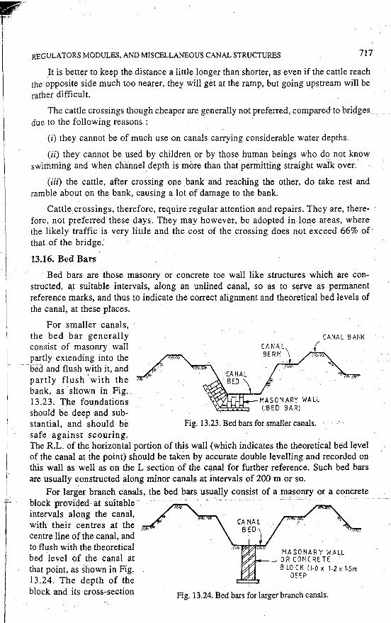
13.16. Bed Bars
Bed bars are those masonry or concrete toe wall like structures which are constructed, at suitable intervals, along an unlined canal, so as to serve as permanent reference marks, and thus to indicate the correct alignment and theoretical bed levels of the canal, at these places.
For smaller canals, the bed bar generally consist of masonry wall partly extending into the bed and flush with it, and partly flush 'with the bank, as ·shown in Fig. 13.23. The foundations should be deep and sub-stantial, and should be Fig. 13.23. Bed bars for smaller canals. safe against scouring. The R.L. of the. horizontal portion of this wall (which indicates the theoretical bed level of the canal at the point) should be taken by accurate double levelling and recorded on this wall as well as on the L section of the canal for further reference. Such bed bars are usually constructed along minor canals at intervals of 200 m or so.
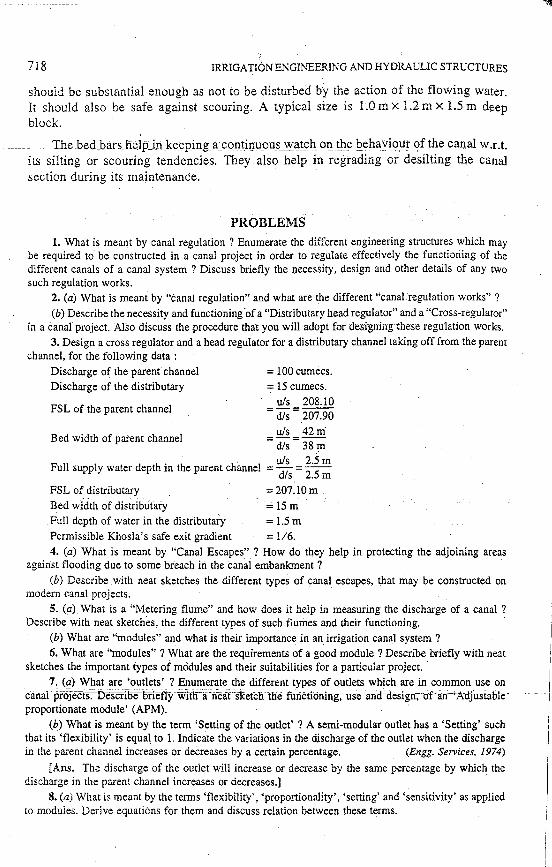
For larger branch canals, the bed bars usually consist of a masonry or a concrete --block provided· at suitable .
intervals along the canal, with their centres at the centre line of the canal, and to flush with the theoretical bed level of the canal at that point, as shown in Fig. 13.24. The depth of the block and its cross-section
MASONARY WALL OR CONCRETE BLOCK fl·O x 1.2 x 1.sm
DEEP
Fig. 13.24. Bed bars for larger branch canals.
718 IRRIGATION ENGINEERING AND HYDRAULIC STRUCTURES
should be substantial enough as not to be disturbed by the action of the flowing water. It should also be safe against scouring. A typical size is 1.0 m x 1.2 m x 1.5 m deep block.
The bed_bars help_in}e_eping_a_con_tinuous watc;h_Of! t_he J:>ehavio_ur <?fthe canal w.r.t. its silting or scouring tendencies. They also help in regrading or desilting the canal section during its maintenance. ·
PROBLEMS 1. What is meant by canal regulation ? Enumerate the different engineering structures which may
be required to· be constructed in a canal project in order to regulate effectively the functioning of the different canals of a canal system ? Discuss briefly the necessity, design and other details of any two such regulation works.
2. (a) What is meant by "canal regulation" and what are the different "canal regulation works" ?
(b) Describe the necessity and functioning ·of a "Dis tributary head regulator" and a "Cross-regulator" in a canal project. Also discuss the procedure that you will adopt for designirrg-these-regulation works.
3. Design a cross regulator and a head regulator for a distributary channel taking off from the parent channel, for the following data :
Discharge of the parent channel Discharge of the distributary
FSL of the parent channel
Bed width of parent channel
= 100 cumecs. = 15 cumecs.
uls 208.10 =dis= 207.90
= uls = 42m· dis 38 m
. . u/s 2.5m Full supply water depth rn the parent channel = dis =
25 m
FSL o~~istributary _ =207.lOm.
Bed width of disfributary = 15 m . Full depth of water in the distributary = 1.5 m
Permissible Khosla's safe exit gradient = 1/6. 4. (a) What is meant by "Canal Escapes" ? How do they help in protecting the adjoining areas
against flooding due to some breach in the canal embankment ?
(b) Describe with neat sketches the different types of canal escapes, that may be constructed on modern canal projects.
5. (a) What is a "Metering flume" and how does it help in measuring the discharge of a canal ? Describe with neat sketches, the different types of such flumes and their functioning. ·
(b) What are "modules" and what is their importance in an irrigation canal system?
6. What are "modules" ? What are the requirements of a good module ? Describe briefly with neat sketches the important types of mooules and their suitabilities for a particular project. ·
7. (a) What are 'outlets' ? Enumerate the different types of outlets which are in common use on canal '"projeeti.'lJescrioeBnefiy wltn'a -n'-eat. s1<etc1rth•e ·runctfoning;- use ·an-d-design-; of. a:n -•Adjustable-' proportionate module' (APM).
(b) What is meant by the term 'Setting of the outlet' ? A semi-modular outlet has a 'Setting' such that its 'flexibility' is equal to 1. Indicate the variations in the discharge of the outlet when the discharge in the parent channel increases or decreases by a certain percentage. (Engg. Services, 1974)
[Ans. The discharge of the outlet will increase or decrease by the same percentage by which the discharge in the parent channel increases or decreases.] -
8. (a) What is meant by the terms 'flexibility', 'proportionality', 'setting' and 'sensitivity' as applied to moduies. Derive equations for them and discuss relation between these terms.
~··
REGULATORS MODULES, AND MISCELLANEOUS CANAL STRUCTURES
(b) Write· note on any two of the following :
(i) Flexible module or Semi-modular type canar outlet
(ii) Standing wave flume
(iii) Canal escapes
(iv) Gibb's rigid module
(v) Proportionai, sub-proportional, and hyper-proportional outlets
(vi) APM type outlet
(vii) Open flume outlet
(viii) Pipe outlets
· (ix). Kennedy's gauge outlet
(x) Cattle crossings
(xi) Bed bars .
719