digital - cnc - motion group cnc.pdf · cnc (g-code) programming today is done with large ... use...
TRANSCRIPT
CNC\CNCPMAN7.WRI 04-00
DIGITAL - CNCTM
STEP MOTION SYSTEM
CNC SYSTEMS MANUAL(REPLACES CNCDEMO MANUAL)
For Use With Software Disk:
DLX 2000(2/3/4 AXES with I/O)REV: 04-00 OR LATER
G-CODE TRANSLATOR / DRIVER SYSTEM
SECTION 1: CNC - G-Code Step Motion Controller
SECTION 2: SMD - Step Motion Drive Assembly
SECTION 3: QUICK Reference Appendix
SECTION 4: Optical Home Sensor Manual
SECTION 5: Trouble & Calibration Manual
SECTION 6: External I/O Controls Manual
BUILT WITH PRIDE IN THE USA
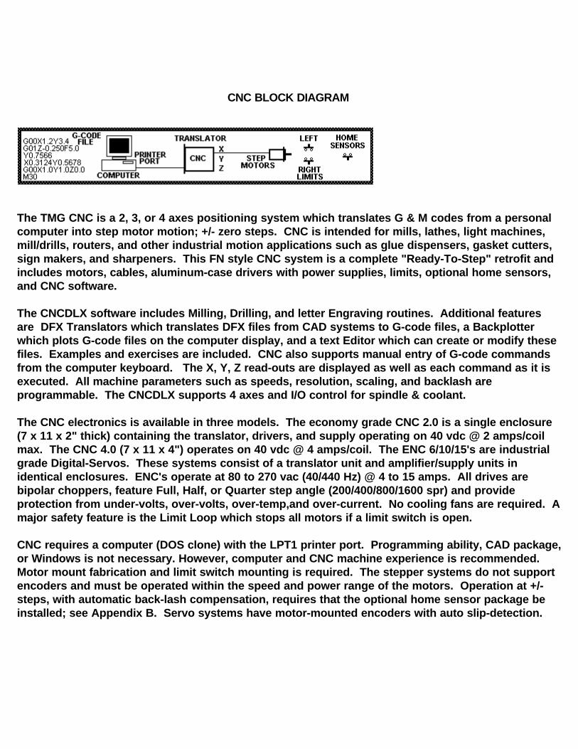
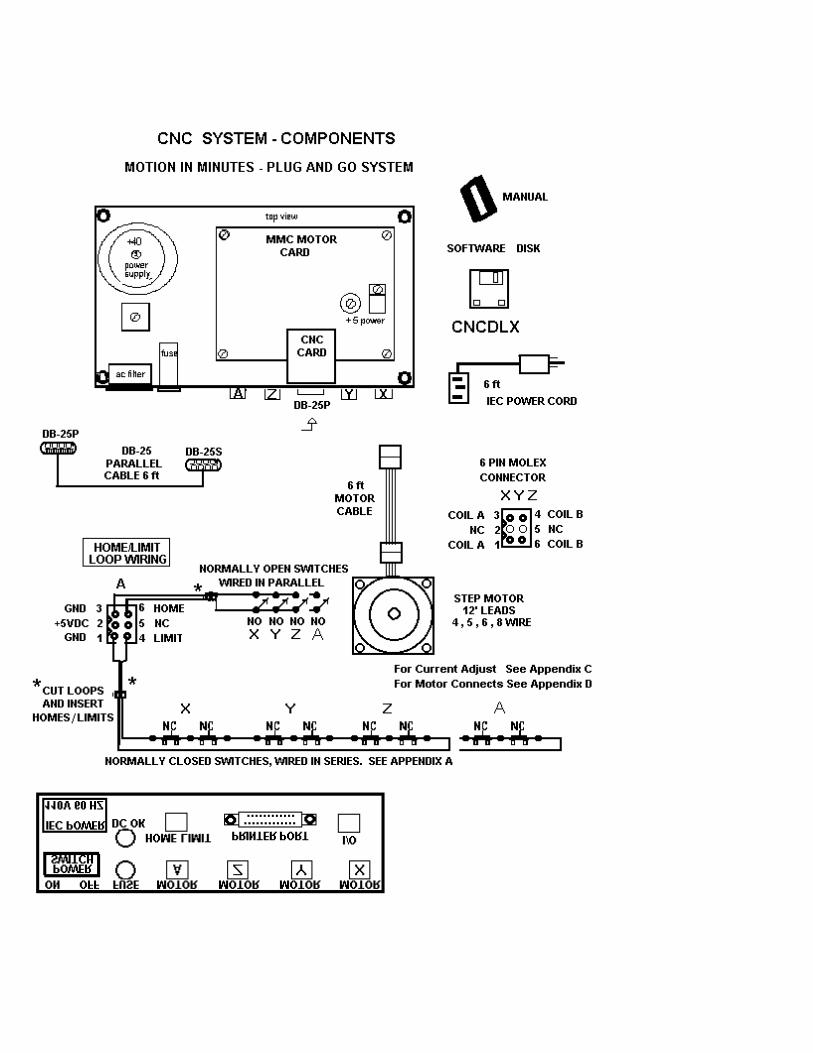
CNC BLOCK DIAGRAM
The TMG CNC is a 2, 3, or 4 axes positioning system which translates G & M codes from a personal computer into step motor motion; +/- zero steps. CNC is intended for mills, lathes, light machines, mill/drills, routers, and other industrial motion applications such as glue dispensers, gasket cutters, sign makers, and sharpeners. This FN style CNC system is a complete "Ready-To-Step" retrofit and includes motors, cables, aluminum-case drivers with power supplies, limits, optional home sensors, and CNC software.
The CNCDLX software includes Milling, Drilling, and letter Engraving routines. Additional features are DFX Translators which translates DFX files from CAD systems to G-code files, a Backplotter which plots G-code files on the computer display, and a text Editor which can create or modify these files. Examples and exercises are included. CNC also supports manual entry of G-code commands from the computer keyboard. The X, Y, Z read-outs are displayed as well as each command as it is executed. All machine parameters such as speeds, resolution, scaling, and backlash are programmable. The CNCDLX supports 4 axes and I/O control for spindle & coolant.
The CNC electronics is available in three models. The economy grade CNC 2.0 is a single enclosure (7 x 11 x 2" thick) containing the translator, drivers, and supply operating on 40 vdc @ 2 amps/coil max. The CNC 4.0 (7 x 11 x 4") operates on 40 vdc @ 4 amps/coil. The ENC 6/10/15's are industrial grade Digital-Servos. These systems consist of a translator unit and amplifier/supply units in identical enclosures. ENC's operate at 80 to 270 vac (40/440 Hz) @ 4 to 15 amps. All drives are bipolar choppers, feature Full, Half, or Quarter step angle (200/400/800/1600 spr) and provide protection from under-volts, over-volts, over-temp,and over-current. No cooling fans are required. A major safety feature is the Limit Loop which stops all motors if a limit switch is open.
CNC requires a computer (DOS clone) with the LPT1 printer port. Programming ability, CAD package,or Windows is not necessary. However, computer and CNC machine experience is recommended. Motor mount fabrication and limit switch mounting is required. The stepper systems do not support encoders and must be operated within the speed and power range of the motors. Operation at +/- steps, with automatic back-lash compensation, requires that the optional home sensor package be installed; see Appendix B. Servo systems have motor-mounted encoders with auto slip-detection.
cnc\ver11-98.wri
TO: CNC 2.0 USERSFROM: TMG SERVICE CENTERSUBJ: UPDATE OF CNC SYSTEMS 12-99.DATE: 12-10-99
THE CNC SYSTEM HAS BEEN UPDATED TO ADVANCED VERSIONS:
(1) THE TERM CNC IS INTERCHANGEABLE WITH CNCPRO OR CNCDLX.(2) THE CNC SOFTWARE IS NOW A DLX2000 DISK(3) THE MACHINE CONTROL PROGRAM IS NOW TMG.EXE.(4) REFER TO THE HOME SWITCH MANUAL SECTION FOR DETAILS OF HOMING.(5) THE REPEAT PROGRAM COMMAND WAS G60; IS NOW M99.(6) THE MAX BACKLASH COMPENSATION WAS 128; IS NOW 255.
USERS OF THE OLDER CNC SYSTEMS SHOULD:
(1) SAVE ANY CUSTOMER .T (G-CODE FILES) PROGRAMS TO THE CNC DISK.
TYPICAL EXAMPLE: C:\CNCxxx\ *.T A:\CNCxxx\ THIS WILL COPY ALL .TPROGRAMS TO THE CNCPRO OR CNCDLX DIRECTORY OF THE A: DRIVE.
(2) ERASE OR REMOVE ALL OLD CNC FILES AND DIRECTORIES FROM C: DRIVE.(3) INSTALL THE NEW CNC SYSTEM.(4) CALL TMG SERVICE CENTER 1-800-424-STEP (7837) FOR ASSISTANCE WITH THE
ABOVE PROCEDURE OR ANY QUESTION.
TO: CNC 2.0 USERS WITH MICROSOFT WINDOWS COMPUTERSFROM: TMG SERVICE CENTERSUBJ: UPDATE OF CNC SYSTEM 3-97 - USER NOTES.DATE: 1-10-98
(1) CNC SYSTEM USERS: CNC SYSTEM G-CODE FOR DELAY IS G04PXXXXWHERE P IS IN MILLISEC. EXAMPLE: G04P2000 WILL DELAY FOR 2 SEC.G92PXXXX DRILL & DELAY IS ALSO OPERATIONAL. ACTUAL DELAY IS AFUNCTION OF TIMESET.EXE WHICH MUST BE RUN IN THE MS-DOS MODE.
(2) CNC MUST BE RUN FROM THE DOS MODE. WINDOWS AND WINDOWS 95 SOFTWARE OPERATION CAUSES "HEARTBEAT" OR "POP-CORN" SOUNDS IN MOTOR TIMING. CLOSE ALL WINDOWS PROGRAMS, RE-START IN MS-DOS MODE.
(3) THE COMPUTER PRINTER PORT MUST BE IN THE LPT MODE; NOT EPP OR BI-DIRECTIONAL. SEE COMPUTER PORT SETUP. COMPAC AND PS2 (IBM) COMPUTERS REQUIRE THESE SPECIAL PRINTER ADDRESSES IN THE PR(PARAMETERS) PROGRAM. RUN PORT.EXE.
12. LPT1 PORT ADDRESS 1 95613. LPT1 PORT ADDRESS 2 95814. LPT1 PORT ADDRESS 3 95715. LPT2 PORT ADDRESS 4 63216. LPT2 PORT ADDRESS 5 63417. LPT2 PORT ADDRESS 6 633
ADDITIONAL CNC INFORMATION. CNC (computer numerical control) language programming is not difficult to learn and the sample programs, included with this system, are typical examples. However, this machine is capable of the very complex operations that some G-codes provide. A complete and detailed understanding of this language is required to take full advantage of those capabilities. Some suggested books are:
CNC A FIRST LOOK PRIMER WILLIAM W. LUGGENFUNDAMENTALS OF NUMERICAL CONTROL WILLIAM W. LUGGENCOMPUTER CONTROL SIMPLIFIED MICHAEL FITZPATRICKCOMPUTER NUMERIC CONTROL G. E. THAYER
ADDITIONAL CAD-CAM SOFTWARE SYSTEMS. CNC (G-code) programming today is done with large graphics computers running 3D CAD-CAM (computer aided drafting - computer aided manufacturing) programs costing thousands of dollars. Some independent CAD-CAM packages such as BOBCAD and DANCAD are less expensive. The next solution is DXF format. These are digital CAD programs which must be translated from DXF (data exchange format) drawings to G-code command NC programs. This CNC system includes a simple DXF translator. An excellent and easy to use CAD-CAM package called POWER-STATION is available from suppliers of low-cost machine tool parts and equipment. This package also does not require a fast graphics computer system. See the flyer page from the Power-Station catalog at the end of this manual. Another type of format is the HPGL drawing format. This is a plotter or 2D system which can be translated (adapted) to a type of 2 & 1/2 D G-code program. HPGL translation is supported by most CAD products. However, any and all G-code programs containing legal codes, and listed in this manual, are fully supported.
!!!! DANGER - ROBOTIC SYSTEM !!!! THIS IS AN AUTOMATIC MACHINE AND CAN START ANY TIME.
Incorrect programming can cause the tool or machine to crash or make sudden uncontrolled moves. This is the MAJOR DANGER. It is therefore required that the Limit Loop Safety be installed. There is no electrical danger from this Electronic Step Motion System any more than any computer system.
!!!! DANGER !!!!TURN SPINDLE POWER SWITCH OFF BEFORE CHANGING TOOLS
USE OF SOME M CODE COMMANDS MAY LEAVE THE MACHINE AXES, CUTTING SPINDLE, OR COOLANT PUMPS PAUSED IN FEED HOLD. TOUCHING THE "C" or "S" KEYS WILL START THE
NEXT COMMAND IN THE NC PROGRAM; CAUSING SUDDEN MOTION OR CUTTING SPINDLE ON. DONOT PAUSE WITH THE SPINDLE ON !
TOUCHING ANY KEYS, COMPUTER GLITCHES, OR POWER SURGES MAY ALSO START THE MACHINE. STAY CLEAR WHEN MACHINE IS "PAUSED".
!!!! ATTENTION !!!!Mis-wiring of motor or power supplies WILL damage motor drivers IMMEDIATELY. Motor coils A or B can be reversed; motor will run in the opposite direction. Pairs can be reversed; pair A in coil B for example. CROSS-WIRING, an A and B wire crossed, WILL damage driver. Allowing exposed motor leads to touch each other, ground, or power MAY damage driver. Refer to Appendix D in the MS driver section for wiring schemes.
SMOKE, POPPING, ELECTRONIC ODOR, OR FUSE FAILURE INDICATES DRIVER FAILURE.
Call the Service Center. Do NOT change fuse or attempt repair without instructions. ADDITIONAL DAMAGE CAN OCCUR !!! Shorted drivers can easily be repaired (over-night) by trained replacement of modular driver arrays.
!!!! WARNING !!!!NEVER connect or disconnect any of the motor leads before disconnecting AC power! Unit may be safely operated WITHOUT motor. However, pause 30 seconds after power off before re-connecting motor (allow Bleed-Down time).
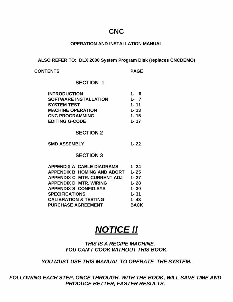
CNC
OPERATION AND INSTALLATION MANUAL
ALSO REFER TO: DLX 2000 System Program Disk (replaces CNCDEMO)
CONTENTS PAGE
SECTION 1
INTRODUCTION 1- 6SOFTWARE INSTALLATION 1- 7SYSTEM TEST 1- 11MACHINE OPERATION 1- 13 CNC PROGRAMMING 1- 15EDITING G-CODE 1- 17
SECTION 2
SMD ASSEMBLY 1- 22
SECTION 3
APPENDIX A CABLE DIAGRAMS 1- 24APPENDIX B HOMING AND ABORT 1- 25APPENDIX C MTR. CURRENT ADJ 1- 27APPENDIX D MTR. WIRING 1- 28APPENDIX S CONFIG.SYS 1- 30SPECIFICATIONS 1- 31CALIBRATION & TESTING 1- 43PURCHASE AGREEMENT BACK
NOTICE !! THIS IS A RECIPE MACHINE.
YOU CAN'T COOK WITHOUT THIS BOOK.
YOU MUST USE THIS MANUAL TO OPERATE THE SYSTEM.
FOLLOWING EACH STEP, ONCE THROUGH, WITH THE BOOK, WILL SAVE TIME AND PRODUCE BETTER, FASTER RESULTS.
INTRODUCTION
The start-up of this system is in three phases: software operation & installation, motor system setup & test, and machine operation. It is important to carefully follow each step as careless work can damage the electronics system and creates the risk of possible injury. NOTE: NEVER MIX / USE "MAXNC" PROGRAMS WITH THIS SYSTEM. NEVER MIX / USE OLD CNCPRO or CNCDLX PROGRAMS WITH THIS DLX2000 SYSTEM.
Hardware Configuration. The MMC (multiple motor controller) card contains the stepper motor drivers. Refer to Section Three for details of the motor drivers. The CNC (Computerized Numeric Control) card contains the CNC translator, serial EPROM memory, memory latches, multiplexer, parallel port receiver/driver, and LED status lites. The CNC card is connected as an LPT parallel device and communicates with the host computer through the front panel DB-25P connector.
Software Configuration. Software consists of five main elements: CNC Machine, Plotter (2D & 3D), Mill Translators, Drill Translator, and Engraver.
TMG loads and executes G-code files (.T files) either in automatic or single step. The G-codes are decoded into motion commands and transmitted to the motor driver system. Limited to files under 300K bytes. Use DNC mode for files up to hard drive capacity.
PLOTL (2D or 3D) plots G-code files on the video display in simulation of the NC program. See CAR3.T for 3D plot sample.
MILL (3 axes), MILLC5 (Corel 5, 3 axes), and MILL4X (4 axes) translate DXF (.dxf) polyline files from popular CAD systems into G-codes. This program is best suited for milling paths. DRILL is both an automatic DXF point translator or a keyboard drill file generator. Special Z motion routines speed up the drilling process.
E & E2, the engravers, translate characters from the font package, which consists of individual character G-codes, into strings of G-code files.
Data files (.dat) store the parameters for the setup and control programs. Other programs (.pcx, .pif,) are internal computer information.
Computer System. This system is configured for DOS clone systems; 286 through P II, from 10 to 225 MHz; with VGA or better displays. The software disk can be installed to the computer hard drive (C drive) or can be directly run from the floppy drive (A drive). The DOS editor, EDIT.EXE is also required. A LPT1 printer card must be installed in the computer system and reside at port address 888 (378Ch), see PORT.EXE for other addresses. Do not leave a printer connected to this port when using CNC.
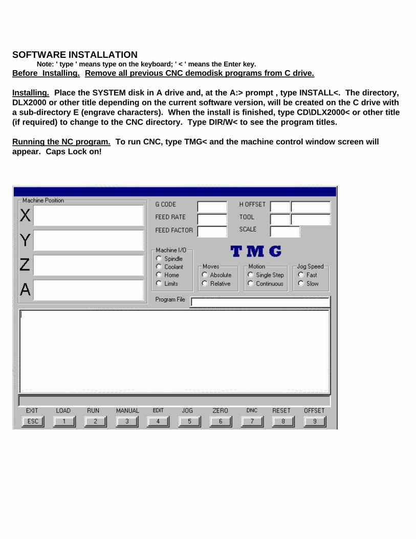
SOFTWARE INSTALLATIONNote: ' type ' means type on the keyboard; ' < ' means the Enter key.
Before Installing. Remove all previous CNC demodisk programs from C drive.
Installing. Place the SYSTEM disk in A drive and, at the A:> prompt , type INSTALL<. The directory, DLX2000 or other title depending on the current software version, will be created on the C drive with a sub-directory E (engrave characters). When the install is finished, type CD\DLX2000< or other title (if required) to change to the CNC directory. Type DIR/W< to see the program titles.
Running the NC program. To run CNC, type TMG< and the machine control window screen will appear. Caps Lock on!
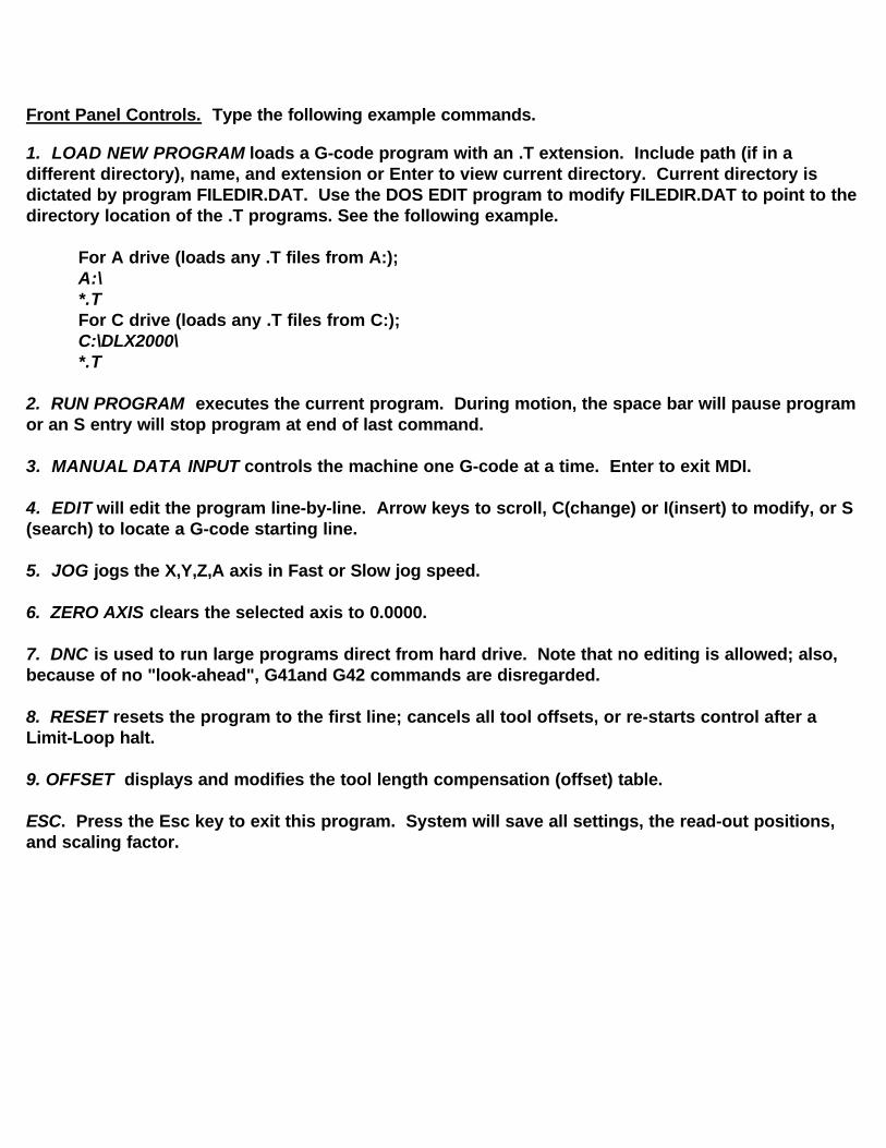
Front Panel Controls. Type the following example commands.
1. LOAD NEW PROGRAM loads a G-code program with an .T extension. Include path (if in a different directory), name, and extension or Enter to view current directory. Current directory is dictated by program FILEDIR.DAT. Use the DOS EDIT program to modify FILEDIR.DAT to point to the directory location of the .T programs. See the following example.
For A drive (loads any .T files from A:);A:\*.TFor C drive (loads any .T files from C:);C:\DLX2000\*.T
2. RUN PROGRAM executes the current program. During motion, the space bar will pause program or an S entry will stop program at end of last command.
3. MANUAL DATA INPUT controls the machine one G-code at a time. Enter to exit MDI.
4. EDIT will edit the program line-by-line. Arrow keys to scroll, C(change) or I(insert) to modify, or S(search) to locate a G-code starting line.
5. JOG jogs the X,Y,Z,A axis in Fast or Slow jog speed.
6. ZERO AXIS clears the selected axis to 0.0000.
7. DNC is used to run large programs direct from hard drive. Note that no editing is allowed; also, because of no "look-ahead", G41and G42 commands are disregarded.
8. RESET resets the program to the first line; cancels all tool offsets, or re-starts control after a Limit-Loop halt.
9. OFFSET displays and modifies the tool length compensation (offset) table.
ESC. Press the Esc key to exit this program. System will save all settings, the read-out positions, and scaling factor.
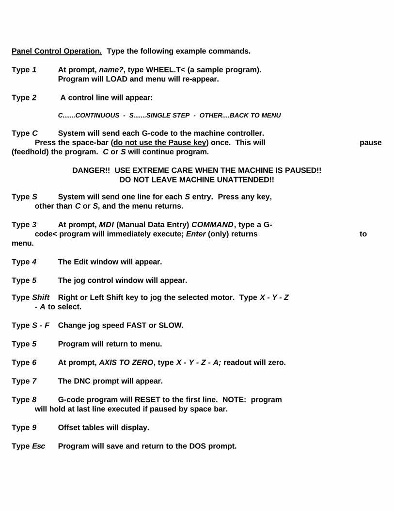
Panel Control Operation. Type the following example commands.
Type 1 At prompt, name?, type WHEEL.T< (a sample program).Program will LOAD and menu will re-appear.
Type 2 A control line will appear:
C.......CONTINUOUS - S.......SINGLE STEP - OTHER....BACK TO MENU
Type C System will send each G-code to the machine controller. Press the space-bar (do not use the Pause key) once. This will pause
(feedhold) the program. C or S will continue program.
DANGER!! USE EXTREME CARE WHEN THE MACHINE IS PAUSED!!DO NOT LEAVE MACHINE UNATTENDED!!
Type S System will send one line for each S entry. Press any key, other than C or S, and the menu returns.
Type 3 At prompt, MDI (Manual Data Entry) COMMAND, type a G-code< program will immediately execute; Enter (only) returns to
menu.
Type 4 The Edit window will appear.
Type 5 The jog control window will appear.
Type Shift Right or Left Shift key to jog the selected motor. Type X - Y - Z - A to select.
Type S - F Change jog speed FAST or SLOW.
Type 5 Program will return to menu.
Type 6 At prompt, AXIS TO ZERO, type X - Y - Z - A; readout will zero.
Type 7 The DNC prompt will appear.
Type 8 G-code program will RESET to the first line. NOTE: program will hold at last line executed if paused by space bar.
Type 9 Offset tables will display.
Type Esc Program will save and return to the DOS prompt.
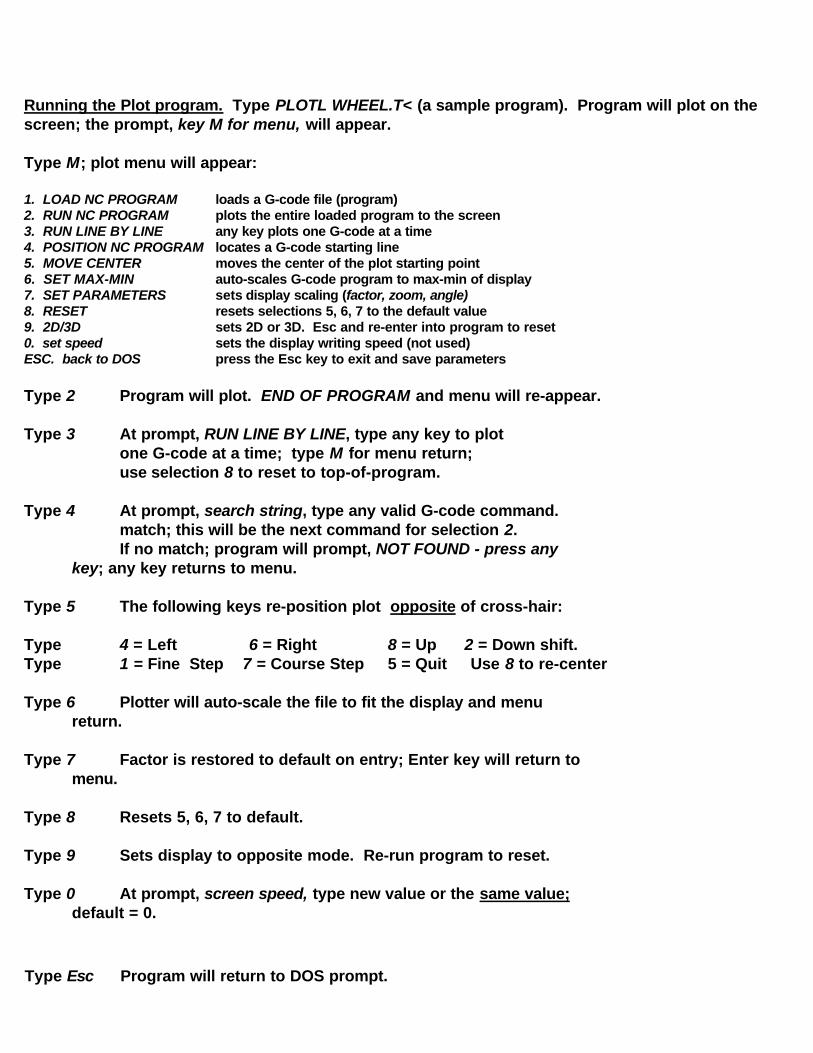
Running the Plot program. Type PLOTL WHEEL.T< (a sample program). Program will plot on the screen; the prompt, key M for menu, will appear.
Type M; plot menu will appear:
1. LOAD NC PROGRAM loads a G-code file (program)2. RUN NC PROGRAM plots the entire loaded program to the screen3. RUN LINE BY LINE any key plots one G-code at a time4. POSITION NC PROGRAM locates a G-code starting line5. MOVE CENTER moves the center of the plot starting point6. SET MAX-MIN auto-scales G-code program to max-min of display7. SET PARAMETERS sets display scaling (factor, zoom, angle) 8. RESET resets selections 5, 6, 7 to the default value9. 2D/3D sets 2D or 3D. Esc and re-enter into program to reset 0. set speed sets the display writing speed (not used)ESC. back to DOS press the Esc key to exit and save parameters
Type 2 Program will plot. END OF PROGRAM and menu will re-appear.
Type 3 At prompt, RUN LINE BY LINE, type any key to plotone G-code at a time; type M for menu return;use selection 8 to reset to top-of-program.
Type 4 At prompt, search string, type any valid G-code command.match; this will be the next command for selection 2.If no match; program will prompt, NOT FOUND - press any
key; any key returns to menu.
Type 5 The following keys re-position plot opposite of cross-hair:
Type 4 = Left 6 = Right 8 = Up 2 = Down shift. Type 1 = Fine Step 7 = Course Step 5 = Quit Use 8 to re-center
Type 6 Plotter will auto-scale the file to fit the display and menu return.
Type 7 Factor is restored to default on entry; Enter key will return to menu.
Type 8 Resets 5, 6, 7 to default.
Type 9 Sets display to opposite mode. Re-run program to reset.
Type 0 At prompt, screen speed, type new value or the same value; default = 0.
Type Esc Program will return to DOS prompt.
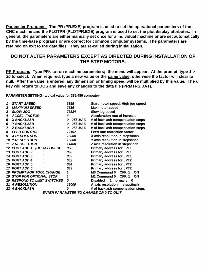
Parameter Programs. The PR (PR.EXE) program is used to set the operational parameters of the CNC machine and the PLOTPR (PLOTPR.EXE) program is used to set the plot display attributes. In general, the parameters are either manually set once for a individual machine or are set automatically by the time-base programs or are correct for common computer systems. The parameters are retained on exit to the data files. They are re-called during initialization.
DO NOT ALTER PARAMETERS EXCEPT AS DIRECTED DURING INSTALLATION OF THE STEP MOTORS.
PR Program. Type PR< to run machine parameters; the menu will appear. At the prompt, type 1 > 20 to select. When required, type a new value or the same value; otherwise the factor will clear to null. After the value is entered, any dimension or timing speed will be multiplied by this value. The 0 key will return to DOS and save any changes to the data file (PRMTRS.DAT).
PARAMETER SETTING- typical value for 386/486 computer-
1 START SPEED 3355 Start motor speed; High jog speed2 MAXIMUM SPEED 2516 Max motor speed3 SLOW JOG 73824 Slow jog speed4 ACCEL. FACTOR 4 Acceleration rate of increase5 X BACKLASH 0 - 255 MAX # of backlash compensation steps6 Y BACKLASH 0 - 255 MAX # of backlash compensation steps7 Z BACKLASH 0 - 255 MAX # of backlash compensation steps8 FEED CONTROL 17197 Feed rate correction factor9 X RESOLUTION 16000 X axis resolution in steps/inch10 Y RESOLUTION 16000 Y axis resolution in steps/inch11 Z RESOLUTION 11400 Z axis resolution in steps/inch12 PORT ADD 1 (DOS-CLONES) 888 Primary address for LPT113 PORT ADD 2 " 890 Primary address for LPT114 PORT ADD 3 " 889 Primary address for LPT115 PORT ADD 4 " 632 Primary address for LPT216 PORT ADD 5 " 634 Primary address for LPT217 PORT ADD 6 " 633 Primary address for LPT218 PROMPT FOR TOOL CHANGE 1 M6 Command 0 = OFF, 1 = ON19 STOP FOR OPTIONAL STOP 1 M1 Command 0 = OFF, 1 = ON 20 RESPOND TO LIMIT SWITCHES 0 Disabled = 1, normally = 021 A RESOLUTION 16000 A axis resolution in steps/inch22 A BACKLASH 0 # of backlash compensation steps
ENTER PARAMETER TO CHANGE OR 0 TO QUIT
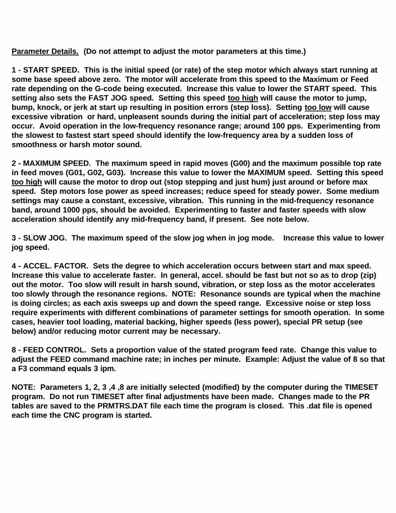
Parameter Details. (Do not attempt to adjust the motor parameters at this time.)
1 - START SPEED. This is the initial speed (or rate) of the step motor which always start running at some base speed above zero. The motor will accelerate from this speed to the Maximum or Feed rate depending on the G-code being executed. Increase this value to lower the START speed. This setting also sets the FAST JOG speed. Setting this speed too high will cause the motor to jump, bump, knock, or jerk at start up resulting in position errors (step loss). Setting too low will cause excessive vibration or hard, unpleasent sounds during the initial part of acceleration; step loss may occur. Avoid operation in the low-frequency resonance range; around 100 pps. Experimenting from the slowest to fastest start speed should identify the low-frequency area by a sudden loss of smoothness or harsh motor sound.
2 - MAXIMUM SPEED. The maximum speed in rapid moves (G00) and the maximum possible top rate in feed moves (G01, G02, G03). Increase this value to lower the MAXIMUM speed. Setting this speed too high will cause the motor to drop out (stop stepping and just hum) just around or before max speed. Step motors lose power as speed increases; reduce speed for steady power. Some medium settings may cause a constant, excessive, vibration. This running in the mid-frequency resonance band, around 1000 pps, should be avoided. Experimenting to faster and faster speeds with slow acceleration should identify any mid-frequency band, if present. See note below. 3 - SLOW JOG. The maximum speed of the slow jog when in jog mode. Increase this value to lower jog speed.
4 - ACCEL. FACTOR. Sets the degree to which acceleration occurs between start and max speed. Increase this value to accelerate faster. In general, accel. should be fast but not so as to drop (zip) out the motor. Too slow will result in harsh sound, vibration, or step loss as the motor accelerates too slowly through the resonance regions. NOTE: Resonance sounds are typical when the machine is doing circles; as each axis sweeps up and down the speed range. Excessive noise or step loss require experiments with different combinations of parameter settings for smooth operation. In somecases, heavier tool loading, material backing, higher speeds (less power), special PR setup (see below) and/or reducing motor current may be necessary.
8 - FEED CONTROL. Sets a proportion value of the stated program feed rate. Change this value to adjust the FEED command machine rate; in inches per minute. Example: Adjust the value of 8 so thata F3 command equals 3 ipm.
NOTE: Parameters 1, 2, 3 ,4 ,8 are initially selected (modified) by the computer during the TIMESET program. Do not run TIMESET after final adjustments have been made. Changes made to the PR tables are saved to the PRMTRS.DAT file each time the program is closed. This .dat file is opened each time the CNC program is started.

9, 10, 11 - RESOLUTION. The resolution for each axis is in steps per inch. This number is the motor resolution times any pulley or belt drive ratio times the axis screw ratio.
Example: 800 (200 spr motor with quad step electronics) x 2 (2:1 belt drive wheels) x 10 (10:1 pitch screw; 10 turns per inch) = 16000 spi.
5, 6, 7 - BACKLASH. Lash in the machine system will be compensated by this value which is in steps per inch. To convert, multiply required inches of compensation by Parameter 9, 10, or 11. Round-off answer to even number of steps. Maximum value is 255; typical value is between 20 to 200.
Example: 16000 spi (resolution) x .005" (required backlash comp.) = 80 (steps/inch).
12, 13, 14 - PORT ADDRESS - LPT1. Parameter 12 controls X and Y motion, 13 controls Z motion, and 14 is Home (G61) input. The decimal values (default = Group A) are for "IBM compatibles" or "DOS clones". Typical values for Compac, HP, and PS2 (which is not a clone), are Group C. Some laptops may require values obtained from the computer documentation or the "Setup" (MSD) program. Run PORT.EXE to see Group values.
15, 16, 17 - PORT ADDRESS - LPT2. Not used in TMG systems.
DANGER! DANGER! DANGER!TURN SPINDLE POWER SWITCH OFF MANUALLY BEFORE CHANGING TOOLS
USE OF THE FOLLOWING OPTIONS LEAVES THE MACHINE PAUSED IN FEED HOLD. TOUCHING THE SPACE BAR WILL START THE NEXT COMMAND IN THE NC PROGRAM; MOTION OR SPINDLE ON. TOUCHING ANY KEYS, COMPUTER
GLITCHES, OR POWER SURGES MAY ALSO START THE MACHINE.
18 - TOOL CHANGE. Setting to 1 enables the M6 command to interrupt the NC program; computer will prompt for tool change if the M6 switch is wired and in the open position. Pushing the switch closed will release the NC program. Set to 0 disables M6 command.
19 - OPTIONAL STOP. Setting to 1 enables any M1 command to stop the NC program (FEED HOLD). Space bar or S command will continue program. Set to 0 disables M1.
DANGER! DANGER! DANGER!TURN SPINDLE POWER SWITCH OFF MANUALLY BEFORE CHANGING TOOLS
20 - LIMIT SWITCH. When set to 0, the software will halt when the TMG hardware Limit-Loop is open. When set to 1, software will ignore limits but hardware will stop. Refer to Limit-Loop; App. B.
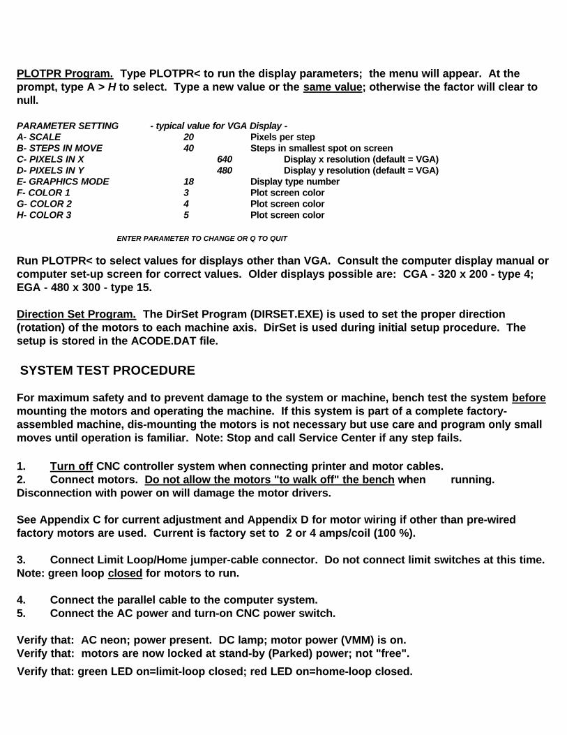
PLOTPR Program. Type PLOTPR< to run the display parameters; the menu will appear. At the prompt, type A > H to select. Type a new value or the same value; otherwise the factor will clear to null. PARAMETER SETTING - typical value for VGA Display -A- SCALE 20 Pixels per stepB- STEPS IN MOVE 40 Steps in smallest spot on screenC- PIXELS IN X 640 Display x resolution (default = VGA)D- PIXELS IN Y 480 Display y resolution (default = VGA)E- GRAPHICS MODE 18 Display type numberF- COLOR 1 3 Plot screen colorG- COLOR 2 4 Plot screen colorH- COLOR 3 5 Plot screen color
ENTER PARAMETER TO CHANGE OR Q TO QUIT
Run PLOTPR< to select values for displays other than VGA. Consult the computer display manual or computer set-up screen for correct values. Older displays possible are: CGA - 320 x 200 - type 4; EGA - 480 x 300 - type 15.
Direction Set Program. The DirSet Program (DIRSET.EXE) is used to set the proper direction (rotation) of the motors to each machine axis. DirSet is used during initial setup procedure. The setup is stored in the ACODE.DAT file.
SYSTEM TEST PROCEDURE
For maximum safety and to prevent damage to the system or machine, bench test the system before mounting the motors and operating the machine. If this system is part of a complete factory-assembled machine, dis-mounting the motors is not necessary but use care and program only small moves until operation is familiar. Note: Stop and call Service Center if any step fails. 1. Turn off CNC controller system when connecting printer and motor cables.2. Connect motors. Do not allow the motors "to walk off" the bench when running. Disconnection with power on will damage the motor drivers.
See Appendix C for current adjustment and Appendix D for motor wiring if other than pre-wired factory motors are used. Current is factory set to 2 or 4 amps/coil (100 %). 3. Connect Limit Loop/Home jumper-cable connector. Do not connect limit switches at this time. Note: green loop closed for motors to run.
4. Connect the parallel cable to the computer system.5. Connect the AC power and turn-on CNC power switch.
Verify that: AC neon; power present. DC lamp; motor power (VMM) is on.Verify that: motors are now locked at stand-by (Parked) power; not "free".
Verify that: green LED on=limit-loop closed; red LED on=home-loop closed.
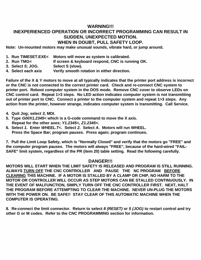
WARNING!!!INEXPERIENCED OPERATION OR INCORRECT PROGRAMMING CAN RESULT IN
SUDDEN, UNEXPECTED MOTION.WHEN IN DOUBT, PULL SAFETY LOOP.
Note: Un-mounted motors may make unusual sounds, vibrate hard, or jump around.
1. Run TIMESET.EXE< Motors will move as system is calibrated.2. Run TMG< If screen & keyboard respond, CNC is running OK.3. Select 5; JOG. Select S (slow).4. Select each axis Verify smooth rotation in either direction.
Failure of the X & Y motors to move at all typically indicates that the printer port address is incorrect or the CNC is not connected to the correct printer card. Check and re-connect CNC system to printer port. Reboot computer system in the DOS mode. Remove CNC cover to observe LEDs on CNC control card. Repeat 1>3 steps. No LED action indicates computer system is not transmitting out of printer port to CNC. Connect a printer to the computer system and repeat 1>3 steps. Any action from the printer, however strange, indicates computer system is transmitting. Call Service.
4. Quit Jog; select 3, MDI.5. Type G00X1.2345< which is a G-code command to move the X axis. Repeat for the other axes; Y1.2345<, Z1.2345<.6. Select 1. Enter WHEEL.T<. Select 2. Select A. Motors will run WHEEL. Press the Space Bar; program pauses. Press again; program continues.
7. Pull the Limit Loop Safety, which is "Normally Closed" and verify that the motors go "FREE" and the computer program pauses. The motors will always "FREE", because of the hard-wired "FAIL-SAFE" limit system, regardless of the PR (item 20) table setting. Read the following carefully.
DANGER!!!MOTORS WILL START WHEN THE LIMIT SAFETY IS RELEASED AND PROGRAM IS STILL RUNNING. ALWAYS TURN OFF THE CNC CONTROLLER AND PAUSE THE NC PROGRAM BEFORE CLEARING THIS MACHINE. IF A MOTOR IS STALLED BY A CLAMP OR CHIP, NO HARM TO THE MOTOR OR CONTROLLER WILL OCCUR AS STEP MOTORS CAN BE STALLED CONTINUOUSLY. IN THE EVENT OF MALFUNCTION, SIMPLY TURN OFF THE CNC CONTROLLER FIRST. NEXT, HALT THE PROGRAM BEFORE ATTEMPTING TO CLEAR THE MACHINE. NEVER UN-PLUG THE MOTORS WITH THE POWER ON. BE SAFE!! STAY CLEAR OF THIS AUTOMATIC MACHINE WHEN THE COMPUTER IS OPERATING.
8. Re-connect the limit connector. Return to select 8 (RESET) or 5 (JOG) to restart control and try other G or M codes. Refer to the CNC PROGRAMMING section for information.
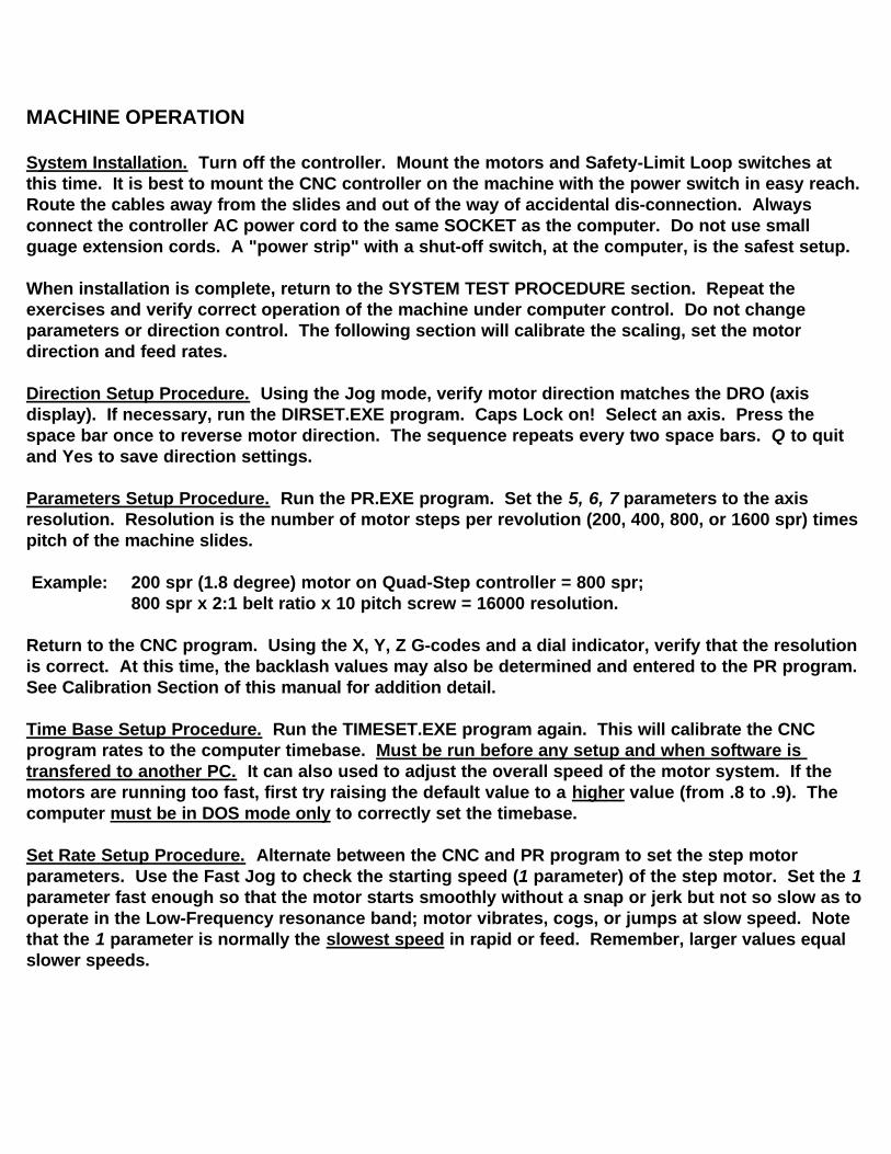
MACHINE OPERATION System Installation. Turn off the controller. Mount the motors and Safety-Limit Loop switches at this time. It is best to mount the CNC controller on the machine with the power switch in easy reach. Route the cables away from the slides and out of the way of accidental dis-connection. Always connect the controller AC power cord to the same SOCKET as the computer. Do not use small guage extension cords. A "power strip" with a shut-off switch, at the computer, is the safest setup.
When installation is complete, return to the SYSTEM TEST PROCEDURE section. Repeat the exercises and verify correct operation of the machine under computer control. Do not change parameters or direction control. The following section will calibrate the scaling, set the motor direction and feed rates.
Direction Setup Procedure. Using the Jog mode, verify motor direction matches the DRO (axis display). If necessary, run the DIRSET.EXE program. Caps Lock on! Select an axis. Press the space bar once to reverse motor direction. The sequence repeats every two space bars. Q to quit and Yes to save direction settings.
Parameters Setup Procedure. Run the PR.EXE program. Set the 5, 6, 7 parameters to the axis resolution. Resolution is the number of motor steps per revolution (200, 400, 800, or 1600 spr) times pitch of the machine slides.
Example: 200 spr (1.8 degree) motor on Quad-Step controller = 800 spr; 800 spr x 2:1 belt ratio x 10 pitch screw = 16000 resolution.
Return to the CNC program. Using the X, Y, Z G-codes and a dial indicator, verify that the resolution is correct. At this time, the backlash values may also be determined and entered to the PR program. See Calibration Section of this manual for addition detail.
Time Base Setup Procedure. Run the TIMESET.EXE program again. This will calibrate the CNC program rates to the computer timebase. Must be run before any setup and when software is transfered to another PC. It can also used to adjust the overall speed of the motor system. If the motors are running too fast, first try raising the default value to a higher value (from .8 to .9). The computer must be in DOS mode only to correctly set the timebase.
Set Rate Setup Procedure. Alternate between the CNC and PR program to set the step motor parameters. Use the Fast Jog to check the starting speed (1 parameter) of the step motor. Set the 1 parameter fast enough so that the motor starts smoothly without a snap or jerk but not so slow as to operate in the Low-Frequency resonance band; motor vibrates, cogs, or jumps at slow speed. Note that the 1 parameter is normally the slowest speed in rapid or feed. Remember, larger values equal slower speeds.

Write down the Feed Control (8 parameter) selected by TIMESET.EXE. Set the Feed Control (8 parameter) to 1; no feed speed at this time. Command G00 moves long enough so that the motor reaches, after acceleration, maximum speed. Note in this move that the motor starts at the Start (1) speed, accelerates at the Accel. (4) factor, runs at the Maximum (2) speed until close to the end of the move, then de-accelerates down to the Start (1) speed, and stops. Set the 2 parameter lower (faster speed) until the motor stalls at the top speed. Note that the motor will "pull-in" and turn when the de-acceleration reaches the 1 speed. Increase the value until the slide moves as fast as possible, or as desired, without stalling. Load the slide with the hand to insure sufficient power. Stepper motors have maximum power at starting speed (pull-in) and minimum power (stalls) at top speed. Set the acceleration (4) factor for a rapid windup but not so rapid as to stall the motor during, or at the top of, acceleration. Too slow an acceleration factor will also stall the motor at the start of the motion.
Note that this is the maximum speed of the machine. It is possible to request high speed Feed Rates, F 500 for example, but at some point, on the curve, the Feed rate will just be the Maximum speed. At this time, restore the 8 parameter to the original value.
Feed Rate Calibration. Using the example G-code command, G01X2.000F1.0< (move, absolute, x axis, 2.0 inch, feed rate of 1.0 inch per min), time the travel and adjust the Feed (8) factor. The Timeset program value should be close, however, the computer system used is still the controlling factor. Refer to the Parameters Calibration section in the back of this manual for additional information. There is only one feed factor. If the resolutions of the other axes are different, this system will automatically adjust the motor speed of the other axes. Parameters 1 - 4 and 8 are reset by TIMESET.EXE.
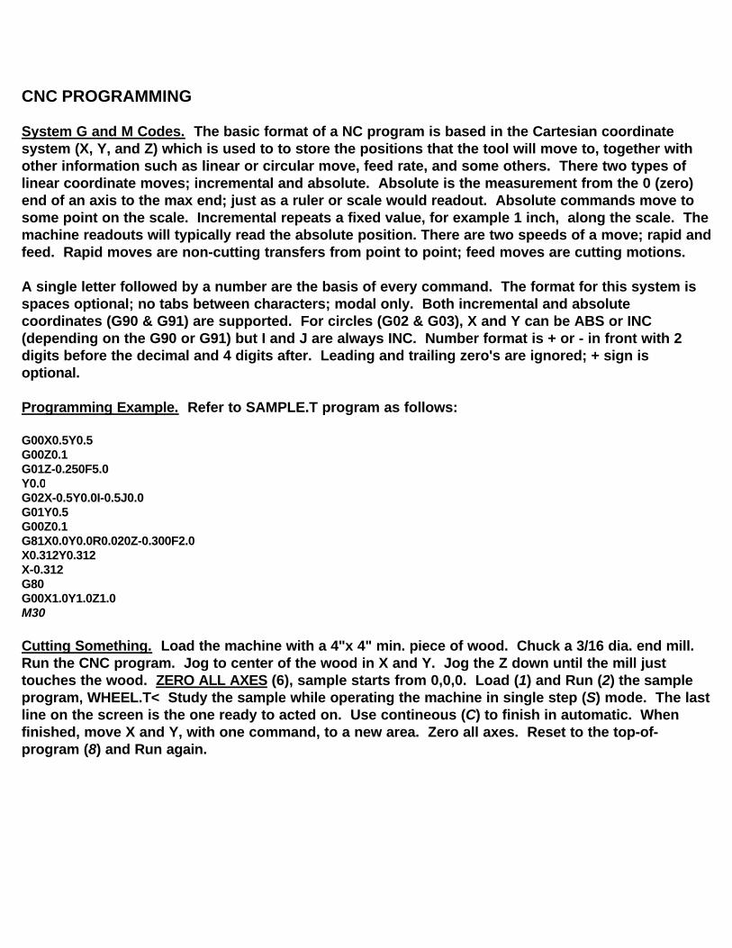
CNC PROGRAMMING
System G and M Codes. The basic format of a NC program is based in the Cartesian coordinate system (X, Y, and Z) which is used to to store the positions that the tool will move to, together with other information such as linear or circular move, feed rate, and some others. There two types of linear coordinate moves; incremental and absolute. Absolute is the measurement from the 0 (zero) end of an axis to the max end; just as a ruler or scale would readout. Absolute commands move to some point on the scale. Incremental repeats a fixed value, for example 1 inch, along the scale. The machine readouts will typically read the absolute position. There are two speeds of a move; rapid andfeed. Rapid moves are non-cutting transfers from point to point; feed moves are cutting motions.
A single letter followed by a number are the basis of every command. The format for this system is spaces optional; no tabs between characters; modal only. Both incremental and absolute coordinates (G90 & G91) are supported. For circles (G02 & G03), X and Y can be ABS or INC (depending on the G90 or G91) but I and J are always INC. Number format is + or - in front with 2 digits before the decimal and 4 digits after. Leading and trailing zero's are ignored; + sign is optional.
Programming Example. Refer to SAMPLE.T program as follows:
G00X0.5Y0.5G00Z0.1G01Z-0.250F5.0Y0.0G02X-0.5Y0.0I-0.5J0.0G01Y0.5G00Z0.1G81X0.0Y0.0R0.020Z-0.300F2.0X0.312Y0.312X-0.312G80G00X1.0Y1.0Z1.0M30
Cutting Something. Load the machine with a 4"x 4" min. piece of wood. Chuck a 3/16 dia. end mill. Run the CNC program. Jog to center of the wood in X and Y. Jog the Z down until the mill just touches the wood. ZERO ALL AXES (6), sample starts from 0,0,0. Load (1) and Run (2) the sample program, WHEEL.T< Study the sample while operating the machine in single step (S) mode. The last line on the screen is the one ready to acted on. Use contineous (C) to finish in automatic. When finished, move X and Y, with one command, to a new area. Zero all axes. Reset to the top-of-program (8) and Run again.
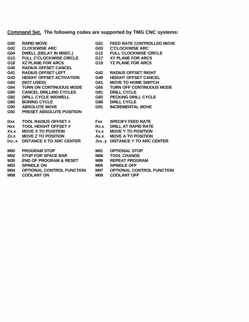
Command Set. The following codes are supported by TMG CNC systems:
G00 RAPID MOVE G01 FEED RATE CONTROLLED MOVEG02 CLOCKWISE ARC G03 C'CLOCKWISE ARCG04 DWELL (DELAY IN MSEC.) G12 FULL CLOCKWISE CIRCLEG13 FULL C'CLOCKWISE CIRCLE G17 XY PLANE FOR ARCSG18 XZ PLANE FOR ARCS G19 YZ PLANE FOR ARCSG40 RADIUS OFFSET CANCELG41 RADIUS OFFSET LEFT G42 RADIUS OFFSET RIGHTG43 HEIGHT OFFSET ACTIVATION G49 HEIGHT OFFSET CANCELG60 (NOT USED) G61 MOVE TO HOME SWITCH G64 TURN ON CONTINUOUS MODE G65 TURN OFF CONTINUOUS MODEG80 CANCEL DRILLING CYCLES G81 DRILL CYCLEG82 DRILL CYCLE W/DWELL G83 PECKING DRILL CYCLEG85 BORING CYCLE G86 DRILL CYCLEG90 ABSOLUTE MOVE G91 INCREMENTAL MOVEG92 PRESET ABSOLUTE POSITION
Dxx TOOL RADIUS OFFSET # Fxx SPECIFY FEED RATEHxx TOOL HEIGHT OFFSET # Rx.x DRILL AT RAPID RATEXx.x MOVE X TO POSITION Yx.x MOVE Y TO POSITIONZx.x MOVE Z TO POSITION Ax.x MOVE A TO POSITIONIxx..x DISTANCE X TO ARC CENTER Jxx..y DISTANCE Y TO ARC CENTER
M00 PROGRAM STOP M01 OPTIONAL STOPM02 STOP FOR SPACE BAR M06 TOOL CHANGEM30 END OF PROGRAM & RESET M99 REPEAT PROGRAMM03 SPINDLE ON M05 SPINDLE OFFM04 OPTIONAL CONTROL FUNCTION M07 OPTIONAL CONTROL FUNCTIONM08 COOLANT ON M09 COOLANT OFF
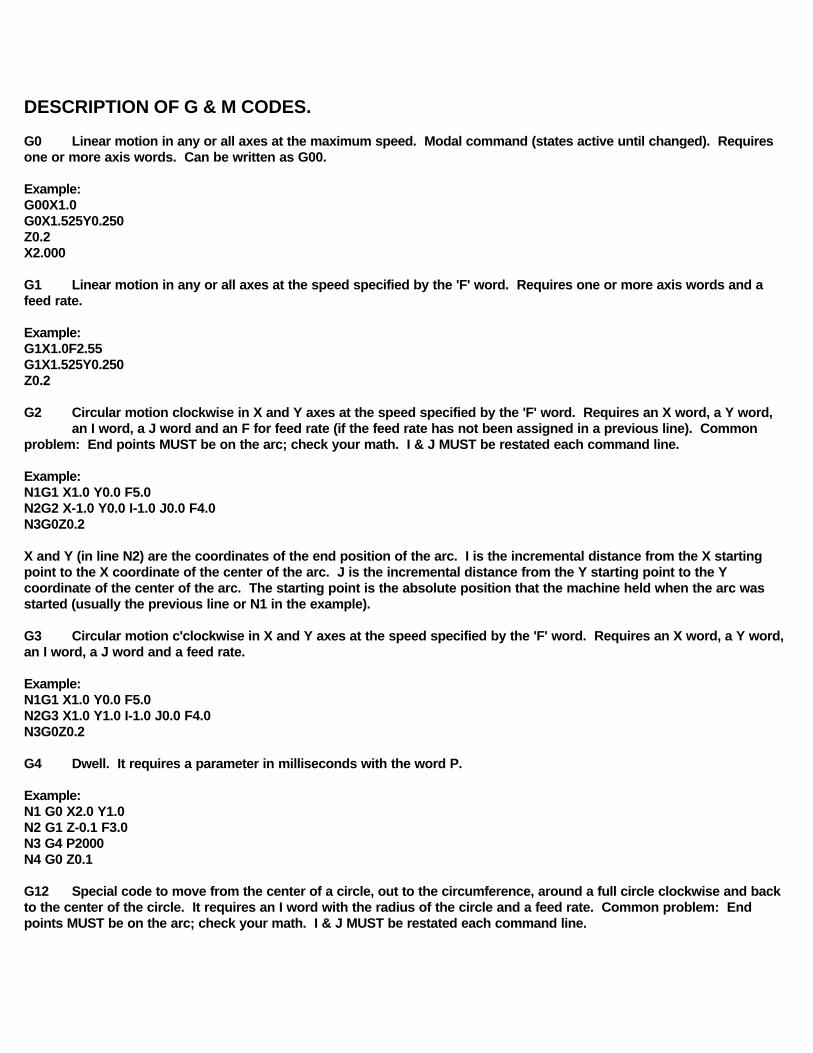
DESCRIPTION OF G & M CODES.
G0 Linear motion in any or all axes at the maximum speed. Modal command (states active until changed). Requires one or more axis words. Can be written as G00.
Example:G00X1.0G0X1.525Y0.250Z0.2X2.000
G1 Linear motion in any or all axes at the speed specified by the 'F' word. Requires one or more axis words and a feed rate.
Example:G1X1.0F2.55G1X1.525Y0.250Z0.2
G2 Circular motion clockwise in X and Y axes at the speed specified by the 'F' word. Requires an X word, a Y word,an I word, a J word and an F for feed rate (if the feed rate has not been assigned in a previous line). Common
problem: End points MUST be on the arc; check your math. I & J MUST be restated each command line.
Example:N1G1 X1.0 Y0.0 F5.0N2G2 X-1.0 Y0.0 I-1.0 J0.0 F4.0N3G0Z0.2
X and Y (in line N2) are the coordinates of the end position of the arc. I is the incremental distance from the X starting point to the X coordinate of the center of the arc. J is the incremental distance from the Y starting point to the Y coordinate of the center of the arc. The starting point is the absolute position that the machine held when the arc was started (usually the previous line or N1 in the example).
G3 Circular motion c'clockwise in X and Y axes at the speed specified by the 'F' word. Requires an X word, a Y word, an I word, a J word and a feed rate.
Example:N1G1 X1.0 Y0.0 F5.0N2G3 X1.0 Y1.0 I-1.0 J0.0 F4.0N3G0Z0.2
G4 Dwell. It requires a parameter in milliseconds with the word P.
Example:N1 G0 X2.0 Y1.0N2 G1 Z-0.1 F3.0N3 G4 P2000N4 G0 Z0.1
G12 Special code to move from the center of a circle, out to the circumference, around a full circle clockwise and back to the center of the circle. It requires an I word with the radius of the circle and a feed rate. Common problem: End points MUST be on the arc; check your math. I & J MUST be restated each command line.
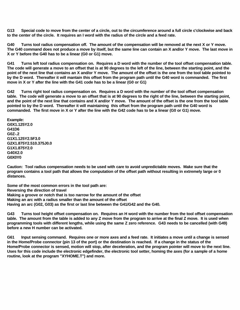
G13 Special code to move from the center of a circle, out to the circumference around a full circle c'clockwise and back to the center of the circle. It requires an I word with the radius of the circle and a feed rate.
G40 Turns tool radius compensation off. The amount of the compensation will be removed at the next X or Y move. The G40 command does not produce a move by itself, but the same line can contain an X and/or Y move. The last move in X or Y before the G40 has to be a linear (G0 or G1) move.
G41 Turns left tool radius compensation on. Requires a D word with the number of the tool offset compensation table. The code will generate a move to an offset that is at 90 degrees to the left of the line, between the starting point, and the point of the next line that contains an X and/or Y move. The amount of the offset is the one from the tool table pointed to by the D word. Thereafter it will mantain this offset from the program path until the G40 word is commanded. The first move in X or Y after the line with the G41 code has to be a linear (G0 or G1)
G42 Turns right tool radius compensation on. Requires a D word with the number of the tool offset compensation table. The code will generate a move to an offset that is at 90 degrees to the right of the line, between the starting point, and the point of the next line that contains and X and/or Y move. The amount of the offset is the one from the tool table pointed to by the D word. Thereafter it will maintaining this offset from the program path until the G40 word is commanded. The first move in X or Y after the line with the G42 code has to be a linear (G0 or G1) move.
Example:G0X1.125Y2.0G41D6G0Z-.2G1X1.125Y2.5F3.0G2X1.875Y2.510.375J0.0G1X1.875Y2.0G40X2.0G0X0Y0
Caution: Tool radius compensation needs to be used with care to avoid unpredictable moves. Make sure that the program contains a tool path that allows the computation of the offset path without resulting in extremely large or 0 distances.
Some of the most common errors in the tool path are:Reversing the direction of travelMaking a groove or notch that is too narrow for the amount of the offset Making an arc with a radius smaller than the amount of the offsetHaving an arc (G02, G03) as the first or last line between the G41/G42 and the G40.
G43 Turns tool height offset compensation on. Requires an H word with the number from the tool offset compensation table. The amount from the table is added to any Z move from the program to arrive at the final Z move. It is used when programming tools with different lengths, while using the same Z zero reference. G43 needs to be cancelled (with G49) before a new H number can be activated.
G61 Input sensing command. Requires one or more axes and a feed rate. It initiates a move until a change is sensed in the Home/Probe connector (pin 13 of the port) or the destination is reached. If a change in the status of the Home/Probe connector is sensed, motion will stop, after deceleration, and the program pointer will move to the next line. Uses for this code include the electronic edgefinder, the electronic tool setter, homing the axes (for a sample of a home routine, look at the program "XYHOME.T") and more.
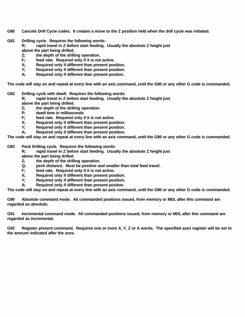
G80 Cancels Drill Cycle codes. It creates a move to the Z position held when the drill cycle was initiated.
G81 Drilling cycle. Requires the following words:R; rapid travel in Z before start feeding. Usually the absolute Z height just above the part being drilled.Z; the depth of the drilling operation.F; feed rate. Required only if it is not active.X; Required only if different than present position.Y; Required only if different than present position.A; Required only if different than present positon.
The code will stay on and repeat at every line with an axis command, until the G80 or any other G code is commanded.
G82 Drilling cycle with dwell. Requires the following words:R; rapid travel in Z before start feeding. Usually the absolute Z height just above the part being drilled.Z; the depth of the drilling operation.P; dwell time in millisecondsF; feed rate. Required only if it is not active.X; Required only if different than present position.Y; Required only if different than present position.A; Required only if different than present position.
The code will stay on and repeat at every line with an axis command, until the G80 or any other G code is commanded.
G83 Peck Drilling cycle. Requires the following words:R; rapid travel in Z before start feeding. Usually the absolute Z height just above the part being drilled.Z; the depth of the drilling operation.Q; peck distance. Must be positive and smaller than total feed travel.F; feed rate. Required only if it is not active.X; Required only if different than present position.Y; Required only if different than present position.A; Required only if different than present positon.
The code will stay on and repeat at every line with an axis command, until the G80 or any other G code is commanded.
G90 Absolute command mode. All commanded positions issued, from memory or MDI, after this command are regarded as absolute.
G91 Incremental command mode. All commanded positions issued, from memory or MDI, after this command are regarded as incremental.
G92 Register present command. Requires one or more X, Y, Z or A words. The specified axes register will be set to the amount indicated after the axes.
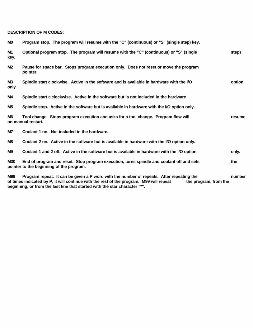
DESCRIPTION OF M CODES:
M0 Program stop. The program will resume with the "C" (continuous) or "S" (single step) key.
M1 Optional program stop. The program will resume with the "C" (continuous) or "S" (single step) key.
M2 Pause for space bar. Stops program execution only. Does not reset or move the program pointer.
M3 Spindle start clockwise. Active in the software and is available in hardware with the I/O option only
M4 Spindle start c'clockwise. Active in the software but is not included in the hardware
M5 Spindle stop. Active in the software but is available in hardware with the I/O option only.
M6 Tool change. Stops program execution and asks for a tool change. Program flow will resume on manual restart. M7 Coolant 1 on. Not included in the hardware.
M8 Coolant 2 on. Active in the software but is available in hardware with the I/O option only.
M9 Coolant 1 and 2 off. Active in the software but is available in hardware with the I/O option only.
M30 End of program and reset. Stop program execution, turns spindle and coolant off and sets the pointer to the beginning of the program.
M99 Program repeat. It can be given a P word with the number of repeats. After repeating the numberof times indicated by P, it will continue with the rest of the program. M99 will repeat the program, from the beginning, or from the last line that started with the star character "*".
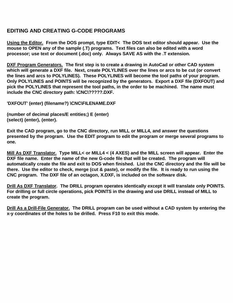
EDITING AND CREATING G-CODE PROGRAMS
Using the Editor. From the DOS prompt, type EDIT< The DOS text editor should appear. Use the mouse to OPEN any of the sample (.T) programs. Text files can also be edited with a word processor; use text or document (.doc) only. Always SAVE AS with the .T extension.
DXF Program Generators. The first step is to create a drawing in AutoCad or other CAD system which will generate a DXF file. Next, create POLYLINES over the lines or arcs to be cut (or convert the lines and arcs to POLYLINES). These POLYLINES will become the tool paths of your program. Only POLYLINES and POINTS will be recognized by the generators. Export a DXF file (DXFOUT) and pick the POLYLINES that represent the tool paths, in the order to be machined. The name must include the CNC directory path: \CNC\?????.DXF.
'DXFOUT' (enter) (filename?) \CNC\FILENAME.DXF
(number of decimal places/E entities;) E (enter)(select) (enter), (enter). Exit the CAD program, go to the CNC directory, run MILL or MILL4, and answer the questions presented by the program. Use the EDIT program to edit the program or merge several programs to one.
Mill As DXF Translator. Type MILL< or MILL4 < (4 AXES) and the MILL screen will appear. Enter the DXF file name. Enter the name of the new G-code file that will be created. The program will automatically create the file and exit to DOS when finished. List the CNC directory and the file will be there. Use the editor to check, merge (cut & paste), or modify the file. It is ready to run using the CNC program. The DXF file of an octagon, X.DXF, is included on the software disk.
Drill As DXF Translator. The DRILL program operates identically except it will translate only POINTS. For drilling or full circle operations, pick POINTS in the drawing and use DRILL instead of MILL to create the program.
Drill As a Drill-File Generator. The DRILL program can be used without a CAD system by entering the x-y coordinates of the holes to be drilled. Press F10 to exit this mode.
Engravers. The Engravers allow typing a character string to engrave. The E and E2 programs differ only in that E sets the length of the letter string and the height is a resultant. E2 sets the height and the length is a result. Run either of the ENGRAVER programs. Type in a character string. Remember to name the program with the directory path and the .T extension; \CNC\?????.T< The resulting program can be examined using the editor. EDIT<; Click FILE; OPEN; then replace the ' .* ' in the file window with .T extension. Changing the SCALE, in the CNC program, or the RESOLUTION of X or Y, in the PR program will also modify the shape or size of the characters. Use the Plot program to examine the two sample programs, ENGRAVE.T and ENGRAVE2.T. The characters are in the \E\ sub directory. Only capital letters are provided in this example.
Helical Interpolation. Refer to the THREAD.T file as an example of helical screw cutting.
Circle and Drill Cycle Example. Refer to the following.
G00Z0.1 (raise Z to the indicated height)G00X0.5Y0.5 (move X & Y, in rapid, to the indicated
position)G01Z-0.250F5.0 (lower Z to the indicated height at feed rate)Y1.0 (Y move at feed rate)GO2X-0.5Y0.0I-0.5J0.0 (make 1/2 circle at feed rate)G00Z0.1 (raise Z, in rapid, to the indicated height)G81X0.0Y0.0R0.02Z-0.3F2 (drill cycle, rapid move in X & Y, then rapid
to R height, drill to Z at feed, and rapid back to R)
X0.123Y0.123 (rapid to X & Y and drill again as before)X-0.555 (repeat drill cycle as before)G80 (cancel drilling cycle and return to Z0.1)G00X1.0Y1.0Z1.0 (rapid move in three axes simultaneously)M30 (end of program and move pointer to
beginning)
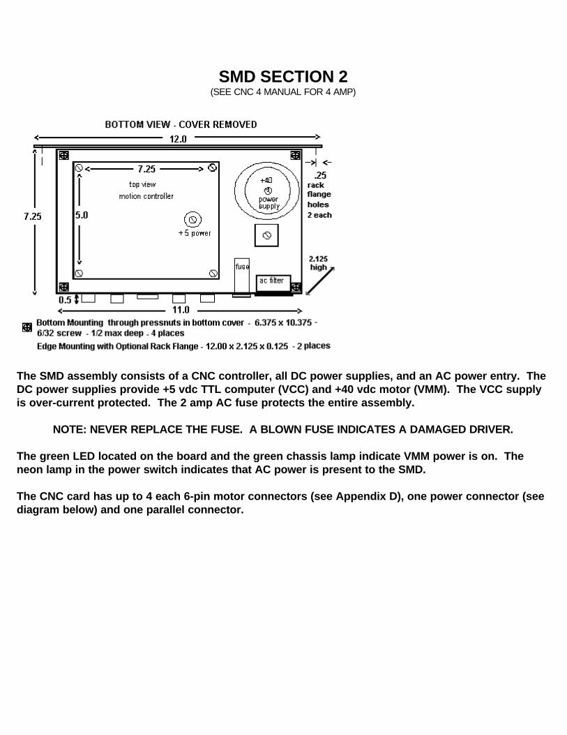
SMD SECTION 2 (SEE CNC 4 MANUAL FOR 4 AMP)
The SMD assembly consists of a CNC controller, all DC power supplies, and an AC power entry. The DC power supplies provide +5 vdc TTL computer (VCC) and +40 vdc motor (VMM). The VCC supply is over-current protected. The 2 amp AC fuse protects the entire assembly.
NOTE: NEVER REPLACE THE FUSE. A BLOWN FUSE INDICATES A DAMAGED DRIVER.
The green LED located on the board and the green chassis lamp indicate VMM power is on. The neon lamp in the power switch indicates that AC power is present to the SMD. The CNC card has up to 4 each 6-pin motor connectors (see Appendix D), one power connector (see diagram below) and one parallel connector.

CNC 2.0 SMD ASSEMBLY TOP VIEW(SEE CNC 4 MANUAL FOR 4 AMP)
CARD CONNECTOR PINOUTS
SMD ASSEMBLY POWER SUPPLY WIRING DIAGRAM
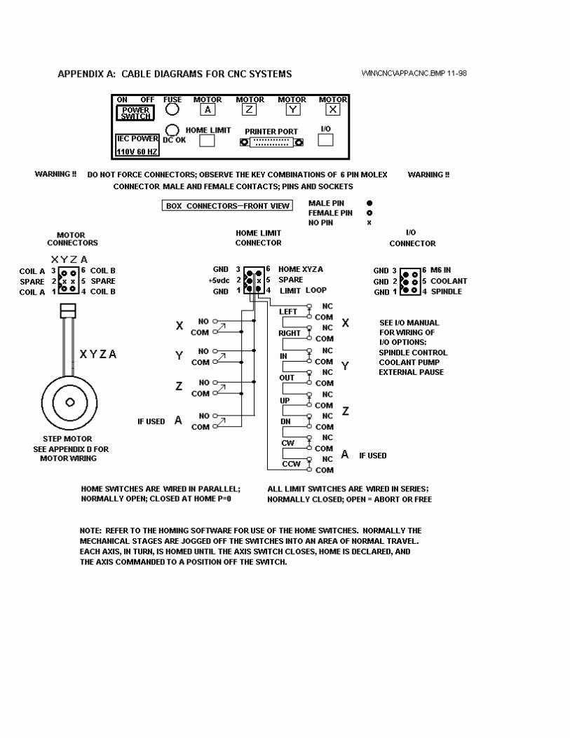
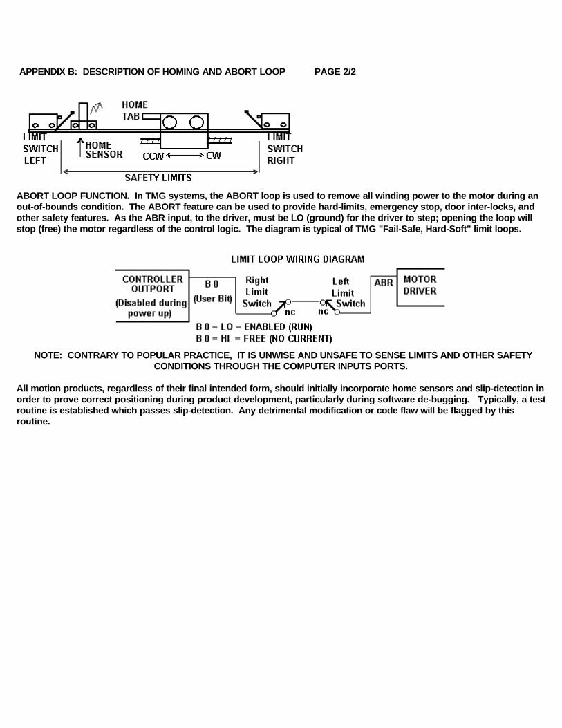
APPENDIX B: DESCRIPTION OF HOMING AND ABORT LOOP PAGE 1/2
HOMING. A major advantage of a digital Open-Loop step system is the ability to operate plus or minus zero steps (no error). Two conditions are required. One is that the motor is sufficient for the load in normal operation and second, that a reference position, commonly called the "home position", be consistently established during initialization of the system. When step motors are rotated by counting (clocking) out a number of steps, in theory, the motion will take place +/- zero steps. The exact mechanical position of the motor can vary by the motor step accuracy; typically +/- 3 % of one step (non-cumlative). A proof of +/- zero step operation is, first, to reference a starting positon of the motor or "home". During homing, the motor is stepped backwards into a switch, reversed, and then stepped forward until the switch opens. The point of interest is not the exact mechanical position but rather on which step the switch changed state.
SLIP-DETECTION. After the motor is home, the controller position counter is reset to the home position, typically position1 (one step out of the sensor). The motor is then stepped CW to any position. To slip-detect the system, the motor is returned to position 1. If the sensor remains open, then the motor is stepped to positon 0. If the sensor closes, the system is operating +/- zero steps (error free). Note that a single step lost (slip) will always result in at least a movement of 4 full steps away from the correct position. Open loop systems are slip-detected at regular intervals to prove continuing slip-free operation.
LASH COMPENSATION. A major advantage of steppers is in their "repeatability" which is typically less than .01 % because the digital controls are not affected by temperature, aging, voltage or adjustment. This allows errors such as lash and distortion to be zeroed-out.
Lash compensation adds or subtracts steps, at each change of direction or because of other forces, to take-up the lash error. Lash compensation is accomplished during the slip-detection process. When the system is slip-detected the first time, the sensor will not close at position 0 because of the lash; home LED remains off. At this point, the system is single-stepped CCW until the sensor closes; home LED is on. The number of CCW steps is the lash compensation value. The system is re-homed and the counter loaded with this value (see At home command). The motor is then moved some number of steps CW, returned to position 1 (sensor open), and finally position 0 (sensor closed). The system is +/- zero steps.
APPENDIX B: DESCRIPTION OF HOMING AND ABORT LOOP PAGE 2/2
ABORT LOOP FUNCTION. In TMG systems, the ABORT loop is used to remove all winding power to the motor during an out-of-bounds condition. The ABORT feature can be used to provide hard-limits, emergency stop, door inter-locks, and other safety features. As the ABR input, to the driver, must be LO (ground) for the driver to step; opening the loop will stop (free) the motor regardless of the control logic. The diagram is typical of TMG "Fail-Safe, Hard-Soft" limit loops.
NOTE: CONTRARY TO POPULAR PRACTICE, IT IS UNWISE AND UNSAFE TO SENSE LIMITS AND OTHER SAFETY CONDITIONS THROUGH THE COMPUTER INPUTS PORTS.
All motion products, regardless of their final intended form, should initially incorporate home sensors and slip-detection in order to prove correct positioning during product development, particularly during software de-bugging. Typically, a test routine is established which passes slip-detection. Any detrimental modification or code flaw will be flagged by this routine.
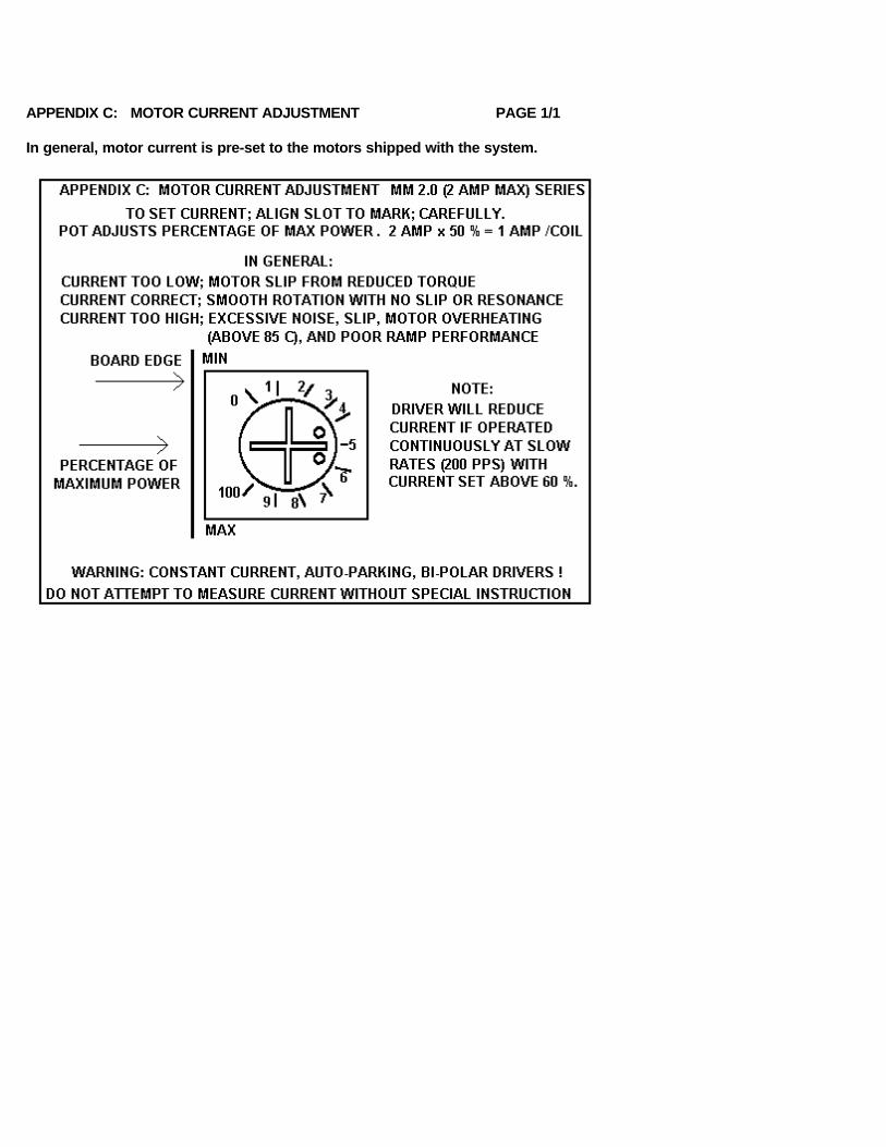
APPENDIX C: MOTOR CURRENT ADJUSTMENT PAGE 1/1
In general, motor current is pre-set to the motors shipped with the system.
APPENDIX D: MOTOR WIRING SCHEMES PAGE 1/2
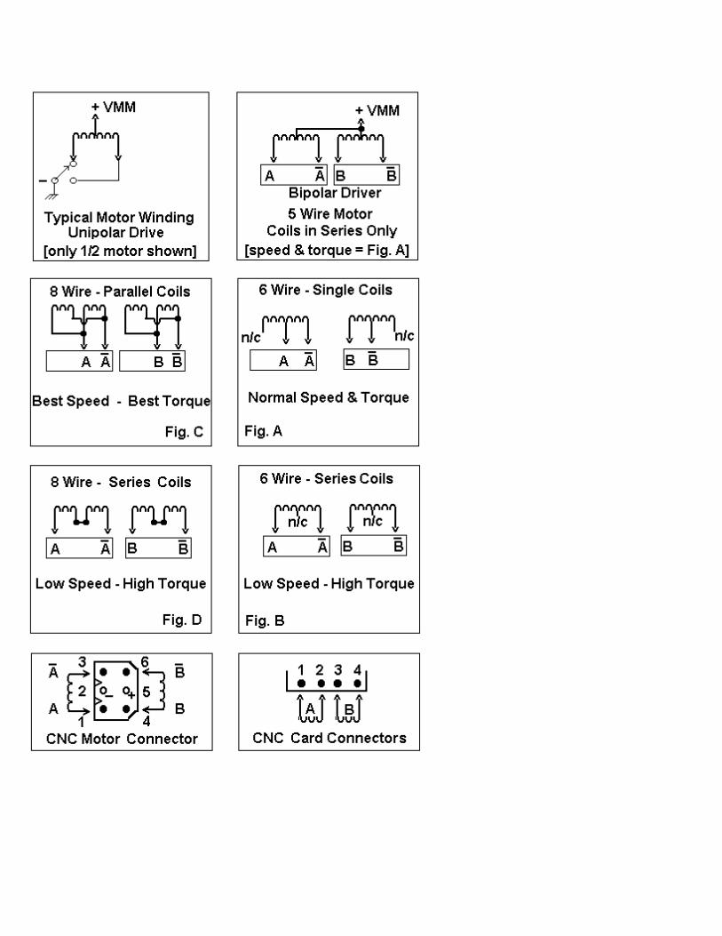
Performance of a stepper motor based system depends more on the electronic drivers used than it does on the motor itself. A step motor (both PM and Hybrid type) is made to step by sequencing the orientations of the magnetic fields in two coils. The UNIPOLAR drive method of is illustrated, in the figure, using just ONE coil of the motor. Note that the center tap of the coil is connected to the positive motor supply voltage. An electronic circuit, represented by the switch, then connects one end or the other to ground for current to flow from the center tap to the grounded end. The most significant factor is that only one-half of the coil is used at any given time and that the magnetic field intensity (motor torque) is proportional to the product of the number of turns in the coil and the current passing through the coil.
Motors designed for BIPOLAR drivers will often have only four leads. However some manufactures will provide the motors in 8 wire versions to offer a performance choice for bipolar drive users as in figures C & D. Four lead bipolar motors may use larger wire, since only half the windings are required in the given space of the motor body. The paralleling in figure C is the equivalent of this to achieve lower winding resistance and thereby doubling motor efficiency. The other alternative for the motor designers is to use a greater number of turns in the winding space. This is shown by figures B & D and results in more torque with a lower coil current but a subsequent loss of high speed torque.
Although step motors are often classified as bipolar or unipolar (2 phase or 4 phase), these terms are more accurately applied to the types of electronic circuit used to drive the motor. Bipolar drivers can drive 4,5,6 and 8 wire motors. When the motor is described as unipolar, the specifications are presented with the assumption that the motor will be driven with a unipolar drive. Therefore the specifications must be translated to bipolar when the motor is used with a bipolar driver. In general, the translation is similar to a unipolar driver with dropping resistors in series with the center taps; referred to as L over x R with R equal to the motor winding resistance. For example, a L over 4R unipolar driver has a resistor equal to 4 times the winding resistance. In bipolar, the L over R ratio is the ratio of the motor voltage to the supply voltage. A L over 4R bipolar drive, for example, would be a 6 volt motor and a 24 volt power supply. Performance would be similar to the L/4R torque curve of a unipolar motor. The figures identify the various connection options when using a bipolar driverwith 6 or 8 wire motors.
A: SINGLE COILS. Identical to unipolar specification (if the supply voltage equals the specified motor voltage). Normal connection of a bipolar driver to 6 wire motor.B & D: SERIES COILS. This configuration will produce torque greater than the unipolar specification indicates. To stay within the power (wattage) rating of the motor, reduce the unipolar specified current by 30%; depending on the duty-cycleof the system (park time). Note that the torque curve of this configuration is considerably fore-shortened as this motor is now the same as a motor with a rating of twice the voltage (slower motor).C: PARALLEL COILS. When this configuration is driven at the unipolar current, the motor will perform identical to the specification but the motor will dissipate only one-half the power (it is twice as efficient). When the current is increased by 1.414, to drive the motor at it's full power rating, the motor torque is increased by approximately 60% Note that this torque curve is extended by four times (high speed system).
Resonance (vibration) of a step motion system depends on the speed and power range of the motor. Fast windings (A & C) are "quicker" and may break into resonance easier than slow (B & D). Power windings (B & D) may deliver "excessive" power (torque) to the system and produce resonance. In general, resonance indicates, except at the low (100 sps) and mid-frequency (1000 sps) bands, excessive power; therefore reduce the driver current for smoother operation or wire the motor for "softer" response.
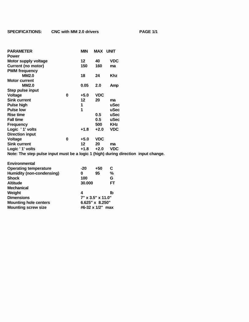
SPECIFICATIONS: CNC with MM 2.0 drivers PAGE 1/1
PARAMETER MIN MAX UNITPower Motor supply voltage 12 40 VDCCurrent (no motor) 150 160 ma PWM frequency
MM2.0 18 24 KhzMotor current
MM2.0 0.05 2.0 AmpStep pulse input Voltage 0 +5.0 VDCSink current 12 20 maPulse high 1 uSecPulse low 1 uSecRise time 0.5 uSecFall time 0.5 uSecFrequency 500 KHzLogic ' 1' volts +1.8 +2.0 VDCDirection input Voltage 0 +5.0 VDCSink current 12 20 maLogic ' 1' volts +1.8 +2.0 VDCNote: The step pulse input must be a logic 1 (high) during direction input change.
EnvironmentalOperating temperature -20 +50 CHumidity (non-condensing) 0 95 %Shock 100 GAltitude 30.000 FTMechanicalWeight 4 lbDimensions 7" x 3.5" x 11.0"Mounting hole centers 6.625" x 8.250"Mounting screw size #6-32 x 1/2" max
CNC\HOME.WRI 1-23-97
DIGITAL - CNCTM
STEP MOTION SYSTEM
HOME SWITCH MANUAL
SECTION 1: Home Switches
SECTION 2: Lash Compensation
SECTION 3: Slip-Detection

CNC HOME SWITCH SYSTEM
Home switches, along with a G-Code HOME routine, are used to establish a repeatable starting position, for the mill, based on three home switches. The optional Photo-Logic home switch system is also used, additionally, to determine the lash compensation value used in the PR table and to slip-detect the system to +/- zero steps.
The following home routine example is typical and must be modified to the configuration of the milling system with respect to the X & Y directions. The G 61 command causes the axis to run the specified direction and distance OR until the switchinput changes state; either on to off or off to on. The G 92 command resets the absolute position of the readout to a specific value.
The home switches are normally located at the X & Y margins and the top of Z; just inside the safety switch loop. In the CNC system, these switches are connected in parallel (see Wiring Diagram) and are Normally Open. Switch opening or closing will trigger the G 61 command. NOTE: Before running the HOME routine, all axes must be manually placed off their switches; only one switch can be used at a time. The HOME indicator LED is normally off and will light when any one of the home switches is closed. After each axis is homed, it is moved to a final position OFF its switch.
Either of two types of switch are used; mechanical or photo-logic. Note that mechanical switches have some switch lash; switch-on is a different point than switch-off. Therefore switch lash must be considered in the total lash compensation. Photo switches are considered as "lash-less"; see Photo-Logic Switches.
HOME ROUTINE SAMPLE PROGRAM
Refer to the HOME.T program during the following explanation. Select the homing speed which is a feed move; F 10 . Clear the axis first; G 92 Z 0.0 . Move (G 61) the axis toward the switch at least the maximum travel possible; in the example, Z travel is 5 inches. The axis will stop at closure of the switch or 5 inches which ever comes first; G 61 Z +5.0. Next, move (G 61) the axis back off the switch, a least a miminum distance (-1.0) across the zero position. If the axis was originally just off the switch, it could stop at the original zero position and not completely release the switch. The axis will stop on opening the switch; G 61 Z -1.0. This position is reset to zero; G 92 Z 0.0. Last, a final small move, away from the switch, insures that the switch is released and completely clear of any backlash motion; G 00 Z -0.001. A final reset establishes the AT Home position, if desired; G 92 Z 0.0.
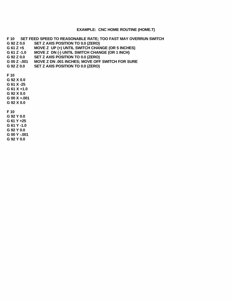
EXAMPLE: CNC HOME ROUTINE (HOME.T)
F 10 SET FEED SPEED TO REASONABLE RATE; TOO FAST MAY OVERRUN SWITCHG 92 Z 0.0 SET Z AXIS POSITION TO 0.0 (ZERO)G 61 Z +5 MOVE Z UP (+) UNTIL SWITCH CHANGE (OR 5 INCHES)G 61 Z -1.0 MOVE Z DN (-) UNTIL SWITCH CHANGE (OR 1 INCH)G 92 Z 0.0 SET Z AXIS POSITION TO 0.0 (ZERO)G 00 Z -.001 MOVE Z DN .001 INCHES; MOVE OFF SWITCH FOR SUREG 92 Z 0.0 SET Z AXIS POSITION TO 0.0 (ZERO)
F 10G 92 X 0.0G 61 X -25G 61 X +1.0G 92 X 0.0G 00 X +.001G 92 X 0.0
F 10G 92 Y 0.0G 61 Y +25G 61 Y -1.0G 92 Y 0.0G 00 Y -.001G 92 Y 0.0

SLIP-DETECTION FOR STEP MOTOR CNC SYSTEMS
The objectives of the home routine are: (1) establish a consistant starting (home) position and (2) allow slip-detection of the system. The major disadvantage of step motion systems that when over-driven, they will slip (drop steps). The major advantage is their repeatability. The slip-detection procedure is used to prove that the system did not slip during execution of a G code program. In slip-detection, the system is first homed. Then the product G code program is executed. Last, each axis is commanded (G61) to find home and paused (M1). The DRO should indicate the original home position and the LED should be ON. Lastly, after pressing the space bar, the machine is moved (G00) forward to the original starting position, off the home sensor. Without the pause, this procedure will produce a quick flash of the home LED. Either case proves the system is still "plus or minus zero steps".
PHOTO-LOGIC HOME SWITCHES
The photo switches used with this CNC system are the reflective type. An infrared beam (.002) is emitted through the window at 45 degrees and when reflected back to the receiver will turn the output on. These switches should be triggered by motion parallel to the window rather than head-on. The reflecting edge should be sharp and well defined; not fuzzy. The reflecting surface should also be .025 to .500 above the window. Use black foam strips to mask off undesired edges. The window blocks ambient light. For best results, do not point (mount) directly at a light source.
BACKLASH CALCULATION USING PHOTO SWITCHES
The following procedure can be used to determine the backlash value used by the PR program. From a CW position, command (G 61) the axis CCW to the home switch, zero the position readout, reverse direction, and command (G61) CW off the home switch. The value in the readout is the lash value in inches. The lash value in the PR table is in steps. For example, if the resolution of the axis is 16000 steps per inch, then each step equals 1/16000 or .0000625 inches per step. A readout of .0009 would be .0009/.0000625 or 14.4 (15) steps of lash compensation. The CNC system will add or subtract 15 steps each time an axis changes direction. The maximum value allowed in the PR table is 255 steps or .015 inches @ 16000 steps/inch.
DIGITAL - CNCTM
STEP MOTION SYSTEM
CNC CALIBRATION MANUALVER: CNC 2.0

SYSTEM TROUBLE-SHOOTING
MISUNDERSTANDINGS OR FALSE ASSUMPTIONS ARE COMMON REASONS FOR SERVICE CALLS.THIS SYSTEM, BUILT WITH PRIDE IN THE USA, WAS TESTED COMPLETELY BEFORE SHIPPING.
PROBLEM: ANSWER:
SYSTEM WON'T WORK; STUPID PRODUCT READ THE MANUAL, AGAIN, STEP-BY-STEP!
NO LAMP/LED'S NO POWER CORD?
NO LAMP/LED'S; BLOWN FUSE; SMOKE/ODOR SYSTEM DOWN; CALL FOR SERVICE
MOTOR JUMPS BACK AND FORTH BLOWN DRIVER; CALL FOR SERVICE
NO JOG; MOTORS FREE; LED'S OFF LIMITS OPEN; INSTALL TEST CABLE
NO JOG; MOTORS FREE; GREEN LED OFF LIMITS OPEN; GREEN LOOP S/B CLOSED
ALL MOTORS NO JOG; MOTORS LOCKED CHECK ALL PRINTER ADDRESSES; SEE PAGE 3
MOTORS JOG TOGETHER; NO JOG ONE MOTOR CHECK 2ND PRINTER ADDRESS IN PR TABLE
NO Z JOG OR NO Z DIRECTION CONTROL CHECK PRINTER PORT MODE; LPT ONLY NOT EPP
MOTOR RUNS WITH BACKGROUND "HEARTBEAT" CLOSE WINDOWS; DOS MODE ONLY
RED HOME LED ALWAYS ON ANOTHER HOME SWITCH IS CLOSED
NO HOME ON ANY AXIS; RED LED ON/OFF IS OK CHECK 3RD PRINTER ADDRESS IN PR TABLE
NO HOME ON AN AXIS; RED LED "FLICKS" ON ANOTHER AXIS TOO CLOSE TO SWITCH
WON'T REPEAT HOME ROUTINE; LED "STICKS" HOMING SPEED TOO FAST; G61 IS A FEED SPEED
MOTORS RUN/HOME BACKWARDS USE DIRSET.EXE PROGRAM TO SET DIR
CAN'T MOVE EXACT AMOUNT; PER INDICATOR PR TABLE "RESOLUTION" ENTRY NOT CORRECT
LASH COMPENSATION NOT CORRECT PR TABLE "LASH COMP" ENTRY NOT IN "STEPS"
LASH COMPENSATION NOT CORRECT CALIBRATE SYSTEM; ADJUST MECHANICS
BACK-LASH PROBLEMS CALIBRATE SYSTEM
SLOW JOG ROUGH OR HARD SLOW JOG SPEED IS TOO SLOW
FAST JOG NO POWER; DROPS STEPS START SPEED TOO HIGH; SLIDE TOO TIGHT
STOPS AND WHINES DURING RAPID MOVE MAX SPEED TOO HIGH; SLIDE TOO LOOSE
GRINDING NOISES DURING ACCELERATION ACCEL. TOO HIGH OR TOO LOW
GRINDING NOISES DURING INTERPOLATION FASTER FEED SPEED; ADJUST ACCEL. FACTOR
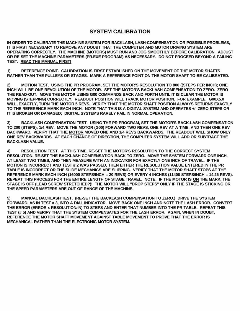
SYSTEM CALIBRATION
IN ORDER TO CALIBRATE THE MACHINE SYSTEM FOR BACKLASH, LASH-COMPENSATION OR POSSIBLE PROBLEMS, IT IS FIRST NECESSARY TO REMOVE ANY DOUBT THAT THE COMPUTER AND MOTOR DRIVING SYSTEM ARE OPERATING CORRECTLY. THE MACHINE (MOTORS) MUST RUN AND JOG SMOOTHLY BEFORE CALIBRATION. ADJUSTOR RE-SET THE MACHINE PARAMETERS (PR.EXE PROGRAM) AS NECESSARY. DO NOT PROCEED BEYOND A FAILING TEST. READ THE MANUAL FIRST!
1) REFERENCE POINT. CALIBRATION IS FIRST ESTABLISHED ON THE MOVEMENT OF THE MOTOR SHAFTS RATHER THAN THE PULLEYS OR STAGES. MARK A REFERENCE POINT ON THE MOTOR SHAFT TO BE CALIBRATED.
2) MOTION TEST. USING THE PR PROGRAM, SET THE MOTOR'S RESOLUTION TO 800 ((STEPS PER INCH); ONE INCH WILL BE ONE REVOLUTION OF THE MOTOR. SET THE MOTOR'S BACKLASH COMPENSATION TO ZERO. ZERO THE READ-OUT. MOVE THE MOTOR USING G00 COMMANDS BACK AND FORTH UNTIL IT IS CLEAR THE MOTOR IS MOVING (STEPPING) CORRECTLY. READOUT POSITION WILL TRACK MOTOR POSITION. FOR EXAMPLE, G00X5.0 WILL, EXACTLY, TURN THE MOTOR 5 REVS. VERIFY THAT THE MOTOR SHAFT POSITION ALWAYS RETURNS EXACTLY TO THE REFERENCE MARK EACH INCH. NOTE THAT THIS IS A DIGITAL SYSTEM AND OPERATES +/- ZERO STEPS OR IT IS BROKEN OR DAMAGED; DIGITAL SYSTEMS RARELY FAIL IN NORMAL OPERATION.
3) BACKLASH COMPENSATION TEST. USING THE PR PROGRAM, SET THE MOTOR'S BACK-LASH COMPENSATIONTO 200 (STEPS); 1/4 REV. MOVE THE MOTOR (G00) FORWARD TWO REVS, ONE REV AT A TIME, AND THEN ONE REV BACKWARD. VERIFY THAT THE MOTOR MOVED ONE AND 1/4 REVS BACKWARDS. THE READOUT WILL SHOW ONLY ONE REV BACKWARDS. AT EACH CHANGE OF DIRECTION, THE COMPUTER SYSTEM WILL ADD OR SUBTRACT THE BACKLASH VALUE.
4) RESOLUTION TEST. AT THIS TIME, RE-SET THE MOTOR'S RESOLUTION TO THE CORRECT SYSTEM RESOLUTION. RE-SET THE BACKLASH COMPENSATION BACK TO ZERO. MOVE THE SYSTEM FORWARD ONE INCH, AT LEAST TWO TIMES, AND THEN MEASURE WITH AN INDICATOR FOR EXACTLY ONE INCH OF TRAVEL. IF THE MOTION IS INCORRECT AND TEST # 2 WAS PASSED, THEN EITHER THE RESOLUTION VALUE ENTERED IN THE PR TABLE IS INCORRECT OR THE SLIDE MECHANICS ARE SLIPPING. VERIFY THAT THE MOTOR SHAFT STOPS AT THE REFERENCE MARK EACH INCH (16000 STEPS/INCH = 20 REVS) OR EVERY 4 INCHES (11400 STEPS/INCH = 14.25 REVS). REPEAT THIS PROCESS FOR THE ENTIRE LENGTH OF STAGE TRAVEL. NOTE: IF THE MOTOR IS ON THE MARK, THE STAGE IS OFF (LEAD SCREW STRETCHED?)! THE MOTOR WILL "DROP STEPS" ONLY IF THE STAGE IS STICKING OR THE SPEED PARAMETERS ARE OUT-OF-RANGE OF THE MACHINE.
5) MANUAL BACKLASH TEST. (RE-SET THE BACKLASH COMPENSATION TO ZERO.) DRIVE THE SYSTEM FORWARD, AS IN TEST # 3, INTO A DIAL INDICATOR. MOVE BACK ONE INCH AND NOTE THE LASH ERROR. CONVERT THE ERROR (ERROR x RESOLUTION/IN) TO STEPS AND ENTER THAT NUMBER INTO THE PR TABLE. REPEAT THIS TEST (# 5) AND VERIFY THAT THE SYSTEM COMPENSATES FOR THE LASH ERROR. AGAIN, WHEN IN DOUBT, REFERENCE THE MOTOR SHAFT MOVEMENT AGAINST TABLE MOVEMENT TO PROVE THAT THE ERROR IS MECHANICAL RATHER THAN THE ELECTRONIC MOTOR SYSTEM.

6) AUTOMATIC BACKLASH TEST. HOME (USING THE G61 COMMAND) THE AXIS BACKWARDS INTO THE HOME SENSOR; THEN HOME THE MOTOR FORWARD. ZERO THE READOUT. USING THE G00 COMMAND, MOVE FORWARD SOME INCHES AND THEN BACKWARDS TO ZERO. NEXT, G61 BACKWARDS TOWARD THE HOME SENSOR; THE READOUT WILL THEN INDICATE A MINUS VALUE EQUAL TO THE BACKLASH IN INCHES. CONVERT THE ERROR (ERROR x RESOLUTION/IN) TO STEPS AND ENTER THAT NUMBER INTO THE PR TABLE. REPEAT THIS TEST AND VERIFY THAT THE SYSTEM COMPENSATES FOR THE LASH ERROR BY OBSERVING THAT THE BACKWARDS G00 MOTION STOPS RIGHT AT THE HOME SENSOR OR THAT THE SUBSEQUENT G61 MINUS MOTION IS MINIMUM.
7) SLIP-DETECTION TEST. SLIP-DETECTION USES THE HOME SWITCHES TO PROVE THAT THE MACHINE REMAINS IN CALIBRATION. WHEN THE SYSTEM IS HOMED (SEE HOME.T), IT IS LEFT AT THE ELECTRONIC REFERENCE (A SMALL NUMBER OF STEPS OFF THE HOME TO PREVENT "TICKLEING" THE SWITCH OR SENSOR). WHEN RUNNING A PART PROGRAM, INCLUDE A HOME ROUTINE; NEXT, MOVE TO THE STARTING POSITION OF THE PART BY COMMAND (DO NOT MOVE THE MACHINE MANUALLY); THEN, EXECUTE THE PART. LAST, HOME (G61) BACKWARDS INTO THE SENSOR AND PAUSE; THE READOUT WILL INDICATE ANY DIFFERENCE BETWEEN THE START AND THE FINISH POSITION. CONTINUE BY RE-HOMING THE AXIS BACK INTO THE REFERENCE POSITION. REPEAT FOR EACH AXIS.
8) DIRECTION TEST. THE DIRTST.T IS A TYPICAL PROGRAM USED TO TEST A MACHINE FOR PROPER OPERATION. IT MAY BE NECESSARY TO EDIT THIS PROGRAM FOR THE MACHINE ON WHICH IT IS INSTALLED. DIRTST.T FIRST HOMES EACH MOTOR. NEXT, EACH MOTOR IS MOVED BACK AND FORTH, BOTH POSITIVE AND NEGATIVE. LAST, EACH MOTOR IS MOVED, BACK AND FORTH, IN A DIRECTION OPPOSITE THE OTHER TWO OR THREE.
ELECTRONIC SYSTEM PROBLEMS ARE SERVICED BY THE MOTION GROUP SERVICE CENTER.
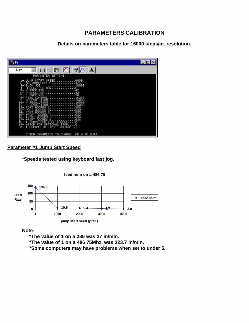
PARAMETERS CALIBRATION
Details on parameters table for 16000 steps/in. resolution.
Parameter #1 Jump Start Speed
*Speeds tested using keyboard fast jog.
feed in/m on a 486 75
139.8
10.5 5.4 3.7 2.80
50
100
150
1 1000 2000 3000 4000
jump start seed (pr#1)
Feed Rate feed in/m
Note: *The value of 1 on a 286 was 27 in/min. *The value of 1 on a 486 75Mhz. was 223.7 in/min. *Some computers may have problems when set to under 5.
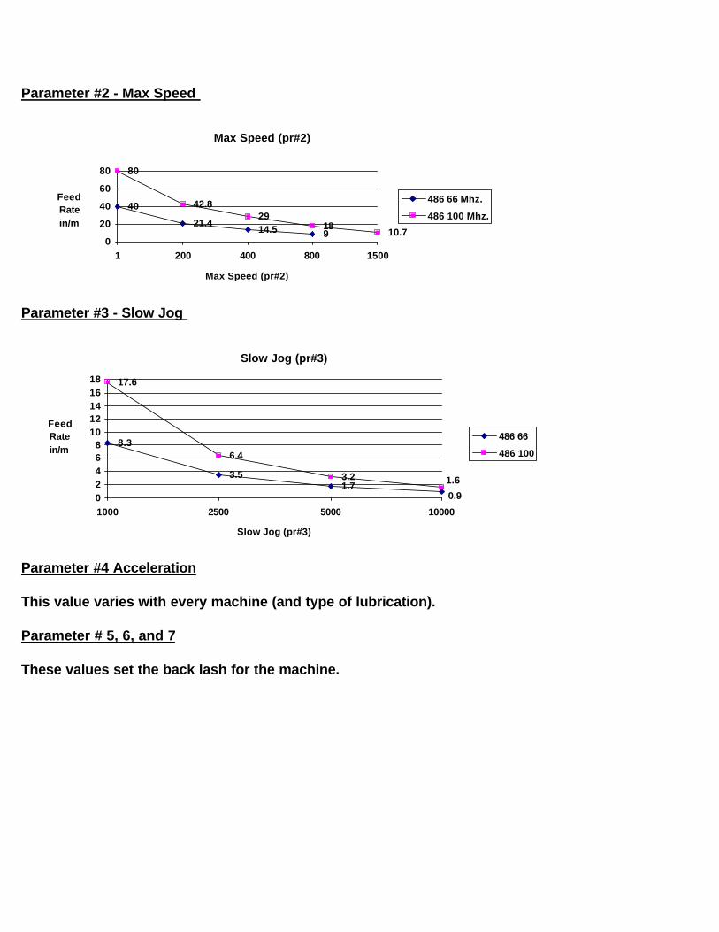
Parameter #2 - Max Speed
Max Speed (pr#2)
40
21.414.5 9
80
42.829
1810.7
0
20
40
60
80
1 200 400 800 1500
Max Speed (pr#2)
FeedRatein/m
486 66 Mhz.
486 100 Mhz.
Parameter #3 - Slow Jog
Slow Jog (pr#3)
8.3
3.51.7
17.6
6.4
3.2
0.9
1.6
02468
1012141618
1000 2500 5000 10000
Slow Jog (pr#3)
FeedRatein/m
486 66
486 100
Parameter #4 Acceleration
This value varies with every machine (and type of lubrication).
Parameter # 5, 6, and 7
These values set the back lash for the machine.

Parameter #8 - Feed Control
This value stays correct for the feedrate used to calibrate it. Slower feedrates are slightly faster than specified, and faster rates are slightly slower.
Feed Control
420
70009025
16235
05000
1000015000
20000
286 486 66 486 75 486 100
CPU clock speed
Feed Control(pr#8) feed control
*486 feed control values were calibrated at 12.5 in/m.
*286 feed control value was calibrated at 1 in/m.
Parameters 9, 10, and 11 resolution
Set these values to the number of steps per inch:(motor steps * gear ratio * screw pitch = steps /inch).
Parameters 12 - 17 Port adresses
These values are "standard" for most pc's except for some Compaq and a few other machines. See Service Notes on front cover.
Parameter #18 - Prompt for Tool Change
Resolution for M6 command
0 - Disabled1 - Software prompt (keyboard space-bar)
Parameter #19 Optional Stop
Resolution for M1 command
0 - Disabled1 - Software prompt (keyboard space-bar)
Parameter # 20 Limit Switches
Set to "1"; software ignores limits. Hardware always stops on limits.
Set to "0"; hard and soft limit stop.

BLANK PAGE
WIN\CNC\CNCIOMAN.WRI REV: 11-98
DIGITAL - CNCTM
STEP MOTION SYSTEMEXTERNAL I/O CONTROL MANUAL
WITH DLX 2000 SOFTWARE ONLY
!!! DANGER !!! ELECTRICAL SHOCK, FIRE, OR INJURY
There is electrical danger of shock, fire, or injury associated with the optional equipment described inthis manual. Only ELECTRICAL or ELECTRONIC technicians qualified to wire electrical circuits at 80 TO 270 VAC power line potential can install these options. Furthermore, the user assumes ALL LIABILITY for any or all equipment to which this option is connected.
THIS IS AN ROBOTIC MACHINE AND CAN START AT ANY TIME.
!!!! DANGER !!!!
BE SAFE ! TURN SPINDLE POWER SWITCH OFF AT THE MANUAL CONTROL BEFORE CHANGING TOOLS
USE OF SOME M CODE COMMANDS MAY LEAVE THE MACHINE AXES, CUTTING SPINDLE, OR COOLANT PUMPS PAUSED IN FEED HOLD. TOUCHING THE "C" or "S" KEYS WILL START THE NEXT COMMAND IN THE NC PROGRAM; CAUSING SUDDEN MOTION OR CUTTING SPINDLE ON. DONOT PAUSE WITH THE SPINDLE ON !
TOUCHING ANY KEYS, COMPUTER GLITCHES, OR POWER SURGES MAY ALSO START THE MACHINE. STAY CLEAR WHEN MACHINE IS "PAUSED".
!!! DANGER !!!BE SAFE ! TURN ALL POWER SWITCHES OFF AT THEIR MANUAL CONTROLS BEFORE POWER-UP, RE-START, OR RE-BOOT OF THE COMPUTER SYSTEM.
MACHINES WIRED WITH THESE OPTIONS WILL CAUSE THE SPINDLE AND COOLANT RELAYS TO PULL-IN MOMENTARILY ANY TIME THE COMPUTER SYSTEM SERVICES (CLEARS) THE PRINTER PORT. THIS IS NORMAL DURING POWER-ON, RE-START, OR RE-BOOT OF THE COMPUTER SYSTEM. USE THE LED TEST CABLE TO VERIFY THE SAFE OPERATION OF THE CNC MACHINE, DURING THESE EVENTS, BEFORE WIRING THE MACHINE WITH AUTOMATIC FUNCTIONS. NOTE ALSO THAT TURNING THE COMPUTER OFF/ON WILL RESET THE RELAYS.
OPERATION AND TEST OF THE M6, M3, AND M8 FUNCTIONS
M6 INPUT CONTROL. The original purpose of the M6 Tool Change control was to hold (pause) the NC program until the tool changer had rotated the next tool into the ready position. More often, in CNC Retro-Fit applications, the M6 is used as a general purpose "Wait-Until" function for parts-in-place, part feeders, clamps down, or covers closed. It is "NOT ALLOWED" to use the external M6 for manual operations or manual tool changing as any switch closure or power glitch could cause the machine to advance. This function is intended for robotic or automatic machine operations only.
DO NOT PLACE HUMAN PARTS IN HARM'S WAY WHEN THIS MACHINE IS IN OPERATION.
To use the M6 feature: 1) Verify that the M6 command is enabled in the PR (parameters table). 2) Issue an M6 command either from the MDI mode or as part of an NC program. 3) On execution of the M6 command, the computer display will flash "tool change" and the NC program will "hold" until the external M6 switch is closed. The NC program will then advance to the next command. To test M6 operation, repeat the above using the MDI mode and the external switch wired into the I/O Test Connector Assembly (see drawing).
M3 or M8 OUTPUT CONTROL. The original purpose of the M3 Spindle On and M8 Coolant On was to turn-on the spindle and the coolant pump with the NC program. More often, in CNC Retro-Fit applications, the M3 and M8 outputs are also used in general purpose functions such as hand-shaking with a PLC controller. It is "NOT ALLOWED" to use the M3 or M8 controls during manual operations as any switch closure or power glitch could cause the machine to advance. This function is intended for robotic or automatic machine operations only.
To use the M3 or M8 feature: 1) Issue an M3 or M8 command either from the MDI mode or as part of an NC program. 2) Onexecution of the M3 or M8 command, the TMGCNC system computer will energize the positive (+) pin, of the I/O connector with +5 vdc. On execution on the M5 (Spindle Off) or the M9 (Coolant Off), the pin will de-energize. The computer display will not provide any signal or warning. The NC program will advance to the next command. To test M3 or M8 operation, repeat the above using the MDI mode and the external (red) LED wired into the I/O Test Connector Assembly (see drawing).
TURNING OFF OR RE-SETTING THE COMPUTER SYSTEM, WILL TURN-OFF THE RELAYS. TURNING OFF THE CNC SYSTEM, EXITING THE PROGRAM, OR PAUSING WILL NOT TURN-OFF THE RELAYS.
LIMIT LOOP SHUT-DOWN SAFETY. On machines wired with the Shut-Down Safety option, opening a limit-loop switch will cause the spindle and coolant relays to drop-out. However, closing that limit-loop switch will pull-in the relays. Therefore, an Emergency Stop (push-off; pull-on "slap-switch") must be installed, typically into the Z-axes limit wiring. In the event the machine is in limits (green LED off), open the slap switch, halt the NC program, and use the MDI mode to turn off the relays before closing the limit-loop.
WARNING! RELAYS WILL RE-START WHEN THE LIMIT SWITCH IS CLOSED IF NOT TURNED OFF BY COMMAND; TURNING OFF THE COMPUTER SYSTEM WILL TURN-OFF THE RELAYS. TURNING OFF THE CNC SYSTEM WILL NOT
TURN-OFF THE RELAYS.
INSTALLATION OF THE M6, M3, AND M8 FUNCTIONS
M6 FUNCTION. To install the M6 switch, connect any "normally-open" (NO) switch or relay to the yellow and orange wires of the I/O connector. Refer to the wiring diagram. Repeat the M6 test procedure to verify operation.
M3 or M8 FUNCTION. The M3 or M8 function requires a "SOLID-STATE" relay of the correct rating for the motors to be controlled. To install the M3 or M8 function, first disconnect the machine AC power cord.
Next, connect the RED [M3] or WHITE [M8] wire to the positive (+) smaller low voltage terminal (3 to 32 vdc) of the relay. Connect the BROWN [M3] or BLACK [M8] wire to the negative (-) smaller low voltage terminal (3 to 32 vdc) of the relay.
Per the wiring diagram, connect the wall-side HOT wire to the larger LINE terminal (110 or 220 vac). Connect the machine-side HOT wire to the LOAD terminal. Connect a standard 110vac neon indicator lamp between the Neutral (white) wire and the LOAD (black or red) wire.
DO NOT PROCEED BEYOND A FAILING STEP. SEEK TRAINED ASSISTANCE OR CALL THE TMG SERVICE CENTER !
1) Turn manual control off; connect AC power; nothing should happen.
2) Turn manual control on; nothing should happen. Turn control off.
3) Using the MDI mode, issue the correct M3 or M8 command; the neon should lite. Some neon lamps may lite dim without the motor load.
4) Turn the manual control on; the motor should run; neon brite.
5) Issue the correct M5 or M9 command and the motor should turn off.
6) Issue M3 or M8 command ; the motor should run; neon brite.
Without cutting tools or fluid, and manual control on, operate the machine and computer system from power-on to NC program dry-run in order to verify the normal operation of the machine relays.
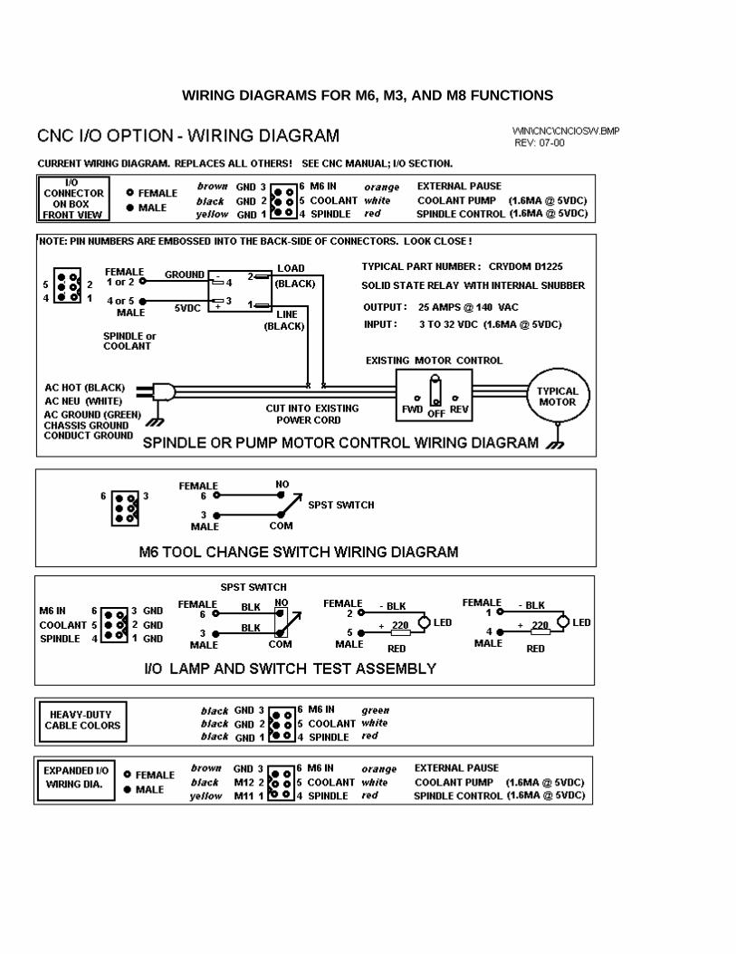
WIRING DIAGRAMS FOR M6, M3, AND M8 FUNCTIONS
BUILT WITH PRIDE IN THE USA