damages to the right pocket of sukkur barrage and
TRANSCRIPT

Paper No. 662
DAMAGES TO THE RIGHT POCKET OF SUKKUR BARRAGE AND
EMERGENCY RESTORATION WORKS (2004-2005)
Barkat Ali Luna, Malik Ahmad Khan, Ch. Muzaffar Hussain, Dr. Muhammad Salik Javed

98 Luna, Khan, Hussain, Javed

Pakistan Engineering Congress, 70th Annual Session Proceedings 99
DAMAGES TO THE RIGHT POCKET OF SUKKUR BARRAGE AND
EMERGENCY RESTORATION WORKS (2004-2005)
(Barkat Ali Luna1, Malik Ahmad Khan2, Ch. Muzaffar Hussain3, Dr. Muhammad Salik Javed4 )
SYNOPSIS 1. Sukkur Barrage and Canals Project was sanctioned on 9th June 1923. The
construction work was started in July 1923 and on completion, the canals were opened on 13th January 1932. The Project was completed at a total cost of about Rs 200 million constituting one of the World’s largest single unified irrigation system.
2. Seventy years after its commissioning, a scour pit was discovered in the u/s stone apron in the right pocket of the Barrage in 2002 during the annual closure. No remedial measures were taken and the damages were allowed to grow un-checked till the closure of 2004. The soundings/ probings observed in the area on January 12, 2004 revealed that the scour pit had grown to an alarming size measuring 60’x40’x9’(Av.) causing collapse of u/s stone apron, first line of sheet piles and a part of the concrete floor u/s Piers 1 & 2. Moreover, cavities had developed under the floor below the crest of the under sluices. Like-wise cavity had been formed under the floor in front of Dadu Canal Head Regulator. The safety of the Barrage on the whole was at stake. The Government of Sindh took immediate notice of the catastrophic situation and constituted a Technical Advisory Committee of Senior Engineers who investigated the situation and advised long term and short term remedial measures for the safety of the Barrage. Accordingly, Irrigation and Power Department framed a Project to carry out the emergency repairs of the damages discovered so as to restore the normal functioning of the right under sluices and save the system from total failure. The execution of the project was assigned to the Frontier Works Organization (FWO) under a special order of the President of Pakistan on the request of Government of Sindh. The Joint Venture of M/s. National Development Consultants (Regd.) – NDC
1 Chairman, National Development Consultants (Regd.). 2 Project Manager, Sukkur Barrage Rehabilitation Project. 3 Dy. Project Manager, Sukkur Barrage Rehabilitation Project. 4 Engineer-in-Chief Branch, GHQ Rawalpindi.

100 Luna, Khan, Hussain, Javed
and M/s. Engineering Associates (Pvt.) Ltd. Karachi (EA) in association with M/s. ATKINS of United Kingdom provided the Consulting Services.
3. Following works were undertaken to repair the damages and restore normal functioning of the Barrage:-
i) Mobilization of man force, equipment and material ii) Construction of coffer dam upstream and downstream of the Right
Undersluices. iii) Construction of Link Canal between Rice Canal and Dadu Canal. iv) Dewatering of the working area v) Removal of sediment deposits/slush from the working area enclosed by
the coffer dams vi) Detailed physical checking of the actual scour caused in the pit and
extent of cavities formed under the main weir floor and the upstream floor of Dadu Canal Head Regulator.
vii) Geophysical investigation in the Right Pocket viii) Sheet piling at the extended upstream and downstream ends of Main
Weir concrete floor. ix) Replacement of old concrete blocks and underneath stone pitching
downstream of the concrete floor by properly designed inverted filter, overlaid by concrete blocks measuring 4’x 4’ x 4’.
x) Provision of settling concrete blocks upstream of concrete floor. xi) Pressure grouting of cavities under the floor by cement sand mix of
proper consistency. xii) Installation of piezometers in the Main Weir and in the floor of Dadu
Canal Head Regulator. xiii) Concreting for extension of upstream floor. xvi) Replenishing deficient stone aprons on upstream and downstream of
the Right Pocket. xv) Removal of upstream and downstream coffer dams. During execution of the works serious challenges and critical situations were
confronted which were tackled with technical skill of the Consultants and the Contractor. The experience gained can be usefully utilized under similar situations for rehabilitation of other barrages in the country.
Pakistan Engineering Congress, 70th Annual Session Proceedings 101
DAMAGES TO THE RIGHT POCKET OF SUKKUR BARRAGE AND EMERGENCY
RESTORATION WORKS (2004-2005)
1. INTRODUCTION Sukkur Barrage is the first barrage on the Indus River constructed in the Sindh Province of Pakistan. It is located about 225 air miles north east of Karachi with coordinates of 68º 33'E, 27º 41'N. It is about 3 miles downstream of Lansdowne Railway Bridge, the twin cites of Sukkur and Rohri being on the right and left banks of the River respectively. The Barrage is situated 100 miles downstream of Guddu Barrage and about 300 miles upstream of Kotri Barrage. Sukkur Barrage and Canals Project was completed at a total cost of about Rs. 20 crores in 1932 and is the World’s largest single unified irrigation network. The Project was sanctioned on June 09, 1923. The work on construction started in July 1923 and the canals were opened on July 13, 1932. Total gross commanded area (GCA) served by the seven off-taking canals is 8.24 million acres on both banks of the Indus River in the middle and lower Sindh. Out of this, 7.55 million acres are cultivable. The maximum withdrawal by all the canals is 64,728 cusecs at present against the total designed capacity of 47,530 cusecs. Sukkur Barrage, originally designed to safely pass a maximum discharge of 15 lac cusecs, comprises 66 bays each of 60 ft clear span and is divided into three sections; the right undersluices, the main weir and the left undersluices. The right and left undersluices have 5 and 7 bays respectively and are separated from the main weir by right and left divide walls on the upstream side. The middle weir portion is divided into six compartments of 9 spans each. The compartments are separated from one another and from the undersluices by 25 ft wide abutment piers. The ordinary piers between the spans are 10 ft wide. A lay out plan and profile of the Barrage are given in Fig. 1.1 and Fig. 1.2. After commissioning of the Barrage in 1932, it was observed that the right bank canals were drawing excessive silt. This situation was put to model studies at Poona Laboratory in India during 1938. The recommendations based on model tests included closing of ten Barrage bays, developing of an island upstream of the closed bays and introduction of certain River training works. After implementation of the recommendations, the maximum discharging capacity of the Barrage was curtailed to 9 lac cusecs. However, discharges over 10 lac cusecs have been experienced thereafter on several occasions. The maximum flood discharge of 12 lac cusecs was passed through the Barrage in 1976.
2. DAMAGES NOTICED DURING THE CLOSURE OF JANUARY 2004
2.1 Nature of Damages and Immediate Measures Taken
102 Luna, Khan, Hussain, Javed
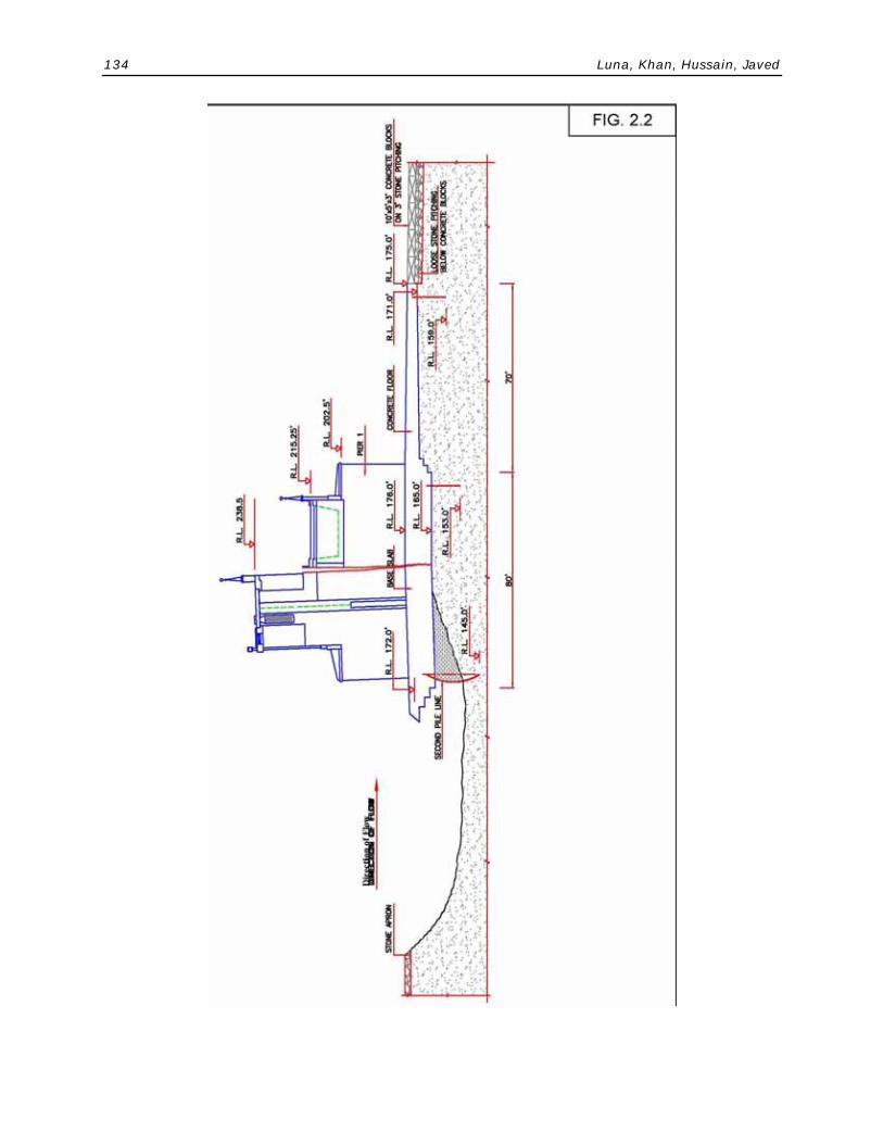
The canals of Sukkur Barrage are closed every year normally from January 06 to 21 to facilitate detailed inspection of under water works and appurtenant components of the Barrage and to provide adequate repairs if any damages are detected. During the annual closure of 2004, while taking soundings in the right pocket u/s of the Barrage on Jan. 12, 2004, a scour pit measuring 60´x 40´x 9´ (Av.) with a maximum depth of 22 feet was discovered in front of Bays No. 1, 2 and 3. The extent of the damage was so grave that the upstream stone apron, first sheet pile line, and part of the concrete floor reaching proximity of the upstream nose of the piers had disappeared in the pit. It was further noticed that the scour pit had extended up to the second line of sheet piles under the Barrage. Similarly a cavity had formed under the floor in front of the Head Regulator of Dadu Canal. The situation was interimly controlled by dumping stone in the pit and limiting the head across to 14 feet against the design limit of 18.5 feet, till such time that the proper rehabilitation works were planned and carried out. A plan and cross-section of the right pocket showing the scour hole are given in Fig. 2.1 and Fig. 2.2 respectively.
2.2 Preliminary Investigations Government of Sindh constituted a Technical/Advisory Committee of senior
engineers to assess: (i) the damage caused to the floor and its likely impact on safety of the structure; (ii) efficacy of given treatment; (iii) recommend short term and long term measures to rectify the situation till next canal closure and to secure safety of Barrage. Later, WAPDA was also requested to examine the problem.
Preliminary investigation reports of Technical/Advisory Committee and Dam Safety Organization, WAPDA (DSO) concluded that the damages in the right pocket could have been triggered by all or one of three factors: Adverse hydraulic conditions causing formation of swirls during flushing operations of the right pocket, swirl formation caused by cross flow from Bay No. 5 to Dadu Canal due to masking of bay Nos. 3, 4 and uneven opening of gates and opening of bottom gates of Dadu Canal head regulator.
3. CONSULTANCY AWARD AND DEPLOYMENT OF FRONTIER WORKS ORGANIZATION (FWO) AS AGENCY FOR EXECUTION OF WORKS.
The Government of Sindh took immediate notice of the critical condition and impaired safety of the Barrage and decided to take up repairs of the damages in the right pocket on war footing. Simultaneously, it was decided to undertake complete review and detailed studies for the Barrage safety using modern approach and technology. The Contract of consultancy services was awarded to the Joint Venture of M/s. National Development Consultants (NDC), Lahore and Engineering Associates (EA) (Pvt.) Limited, Karachi. The execution of works was assigned to Frontier Works Organization (FWO) as a special task under the orders of the President of Pakistan. Both the agencies
Pakistan Engineering Congress, 70th Annual Session Proceedings 103
mobilized immediately and a planning, design and execution strategy was formulated after a series of meetings amongst the Client, FWO and the Consultants.
4. PLANNING FOR EXECUTION OF THE EMERGENCY RESTORATION WORKS
The planning, design and execution of the emergency repair works in the right pocket of the Barrage presented a great challenge. Not only that the scour pit was filled with stone and gunny bags but the entire pocket was choked with sediment deposit right up to the pond level. The scour had gone up to the deepest level of 154 against the designed floor level of 176 and any operation indiscriminately conducted for clearance of the pit could cause further sucking of soil particles from the cavities formed underneath the floor and eventual collapse of the Barrage superstructure. Detailed consultation meetings were held between the Client, Consultants and FWO to evolve a strategy for carrying out the emergency works without jeopardizing the safety of the Barrage. The location and design of coffer dams related logistic arrangements and other issues as given below were discussed in particular:
i) Location and design of coffer dams ii) Section and quantity of sheet piles to be arranged iii) Dewatering arrangements iv) Areas for borrowing earthwork for coffer dams v) Site of erecting bailey bridge vi) Supply and carriage of stone vii) Arrangements of gunny bags viii) Sub-contractors for the specialized jobs of sheet piling, pressure
grouting and dewatering etc. ix) Construction of link channel between Rice Canal and Dadu Canal Based on these discussions a work plan was prepared to streamline the
working modalities and optimize the procurement of resources in order to meet the daunting challenge of the assignment and win the battle against time and odds. Following set of works was planned to accomplish the job:
i) Mobilization of man force, equipment and material ii) Construction of coffer dam upstream and downstream of the Right
Undersluices. iii) Construction of Link Canal between Rice Canal and Dadu Canal. iv) Dewatering of the working area v) Removal of sediment deposits/slush from the working area enclosed by
the coffer dams

104 Luna, Khan, Hussain, Javed
vi) Detailed physical checking of the actual scour caused in the pit and extent of cavities formed under the main weir floor and the upstream floor of Dadu Canal Head Regulator.
vii) Geophysical investigation in the Right Pocket viii) Sheet piling at the extended upstream and downstream ends of Main
Weir concrete floor. ix) Replacement of old concrete blocks and underneath stone pitching
downstream of the concrete floor by properly designed inverted filter, overlaid by concrete blocks measuring 4’x 4’ x 4’.
x) Provision of settling concrete blocks upstream of concrete floor. xi) Pressure grouting of cavities under the floor by cement sand mix of
proper consistency. xii) Installation of piezometers in the Main Weir and in the floor of Dadu
Canal Head Regulator. xiii) Concreting for extension of upstream floor. xiv) Replenishing deficient stone aprons on upstream and downstream of
the Right Pocket. xv) Removal of upstream and downstream coffer dams. All the works were to proceed in a chronological order for completion in the
given time starting from December 2004 to April 2005 working round the clock so that all the non-perennial and perennial channels could be opened in time and no set back was caused to the irrigated agriculture in the command areas.
5. EXECUTION OF WORKS The works were required to be carried out at a very tight time schedule. The
nature of some of the operations involved was quite hazardous and could threaten the very safety of the Barrage. Therefore quick and on the spot decisions were required to handle some of the critical situations so that the work could proceed uninterruptedly.
The execution details of different components of works are described in the following paragraphs with the help of necessary photographs and drawings citing the problems confronted and solutions adopted. The objective of the paper is to share the design and construction experience with brother engineers to have their views on the subject. This would be of great help in tackling similar situations during remodelling of numerous barrages now in progress in the Country.
5.1 Construction of Coffer Dams 5.1.1 Subsurface Investigations on Centre Line of
Cofferdams Two (2) bore holes were drilled on upstream cofferdam site and 5 No.
holes on downstream cofferdam site. The purpose was to find out sub-

Pakistan Engineering Congress, 70th Annual Session Proceedings 105
surface strata for making arrangements to procure specific equipment for driving of sheet piles and drilling for tubewells. The bore hole data showed presence of stone varying from 10 feet to 15 feet below the existing bed levels.
5.1.2 Construction of Upstream Cofferdam a) Coffer dams on the upstream and downstream sides of the right under-
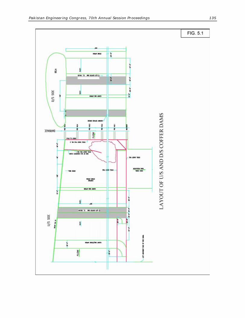
sluices were constructed to isolate the area for carrying out construction activities. The centre line of upstream coffer dam was fixed 300 feet from gate line to leave required space for extension of concrete floor, settling blocks and stone apron. Length of coffer dam between right abutment and divide wall was about 387 feet. The coffer dam was constructed with 40 ft top width, 3:1 side slope on the river side and 2:1 side slope towards the working area, with top level of embankment at EL. 202. The coffer dam was protected against scour at the toe by providing apron of gunny bags filled with material from the bela. Side slopes were protected by providing double row of gunny bags filled with material from the borrow area. The total earth work involved was 0.843 million cft and a total of 67,798 gunny bags were used in apron and side slopes. The layout plan and x-section of the coffer dams showing all the design details are given as Fig. 5.1 and Fig. 5.2 respectively.
b) Special Treatment for Joint with Right Abutment Wall
About 70 ft. portion of the cofferdam towards right abutment was kept open for feeding Dadu Canal and was filled during January closure of 2005. The joint of the earth work with the abutment wall required special treatment being vulnerable to leakage. It was planned to provide 200 ft. clay blanket on the upstream together with stone dumping in case the flow in 70 ft left over portion was excessive. However, during closure of 2005, it was found that the discharge was not high, and, therefore, the proposal was modified. Instead of stone, gunny bags were used in the apron. Moreover, to circumvent any chance of seepage at the joint of earth work with the masonry of abutment wall, puddling and staunching done in layers by use of excavator bucket, and manually by Army Jawans. The contact area of earthwork with the masonry wall was also increased by increasing top width of cofferdam.
c) Driving Sheet Piles at Centre of the Coffer Dams
For seepage control, 189 No. Larson Steel Sheet Piles (PU-12) each of 40 ft. length were driven with Vibro-hammer through the body of the dam down to EL 175, i.e. upto the floor level in front of Dadu Canal Head Regulator and upto EL 160 in the remaining portion by skilful handling. Four sheet piles could not be driven to the required depth due to large stone boulders lying underneath and were left at EL. 166. Two No. sheet piles in front of Bay No. 2 went down with their own weight, which indicated presence of some runnel (or hollow) below that portion. These

106 Luna, Khan, Hussain, Javed
piles were secured in position by welding with the adjacent piles. The provision of sheet piling in the cofferdams served the dual purpose of seepage control and physical stability of the structure. It was later on observed that had the sheet piles not been used, the upstream coffer dam would have given way and breached. The effectiveness of the piles was evident from the toe of downstream slope of coffer dam, which remained completely dry during the construction operation. The following photographs show different stages of construction of upstream cofferdam.
Upstream Coffer Dam under Construction

Pakistan Engineering Congress, 70th Annual Session Proceedings 107
Sheet Piles in Upstream Coffer Dam
Puddling in progress
Completed Upstream Coffer Dam
5.1.3 Construction of Downstream Coffer dam The centre line of cofferdam was fixed 620 ft. from the gate line and 100
ft. downstream of bypass bridge to avoid encountering of loose stone apron on downstream of under-sluices as well as the possible presence of

108 Luna, Khan, Hussain, Javed
stone concrete debris inadvertently left in the pocket during construction of bypass bridge. Top width of the cofferdam was kept 40 ft. and length as 520 ft. at EL-192. The slope on pocket side was kept as 2:1 and river side as 3:1. The stone apron, 20 feet in length, was provided on river side and 10 feet apron of gunny bags was provided on pocket side. The slopes were protected with double layers of gunny bags on both sides. Moreover two (2) rows of R.C.C. pipes were provided underneath the left end of the coffer dam to facilitate drainage of seepage water from the pocket area. No. AU-14 type Larson sheet piles were driven in the body of coffer dam down to EL-159. In downstream cofferdam, 2 No. sheet piles, as happened in case of upstream coffer dam, sank with their own weight in front of Bay No. 2, confirming existence of some runnels (or local hollows).
5.2 Construction of Link Canal at Ruk Complex A link canal was constructed between Rice Canal and Dadu Canal
upstream of Ruk Complex, RD 82 Rice Canal, to provide temporary arrangements for feeding perennial supplies into Dadu Canal during the period the head regulator of Dadu Canal remained closed for execution of emergency works in the right pocket of the Barrage. Irrigation water supply of 2,500 cusecs was routed through the Rice Canal upto RD 82 near Ruk Complex and then diverted into Dadu Canal through the link canal by adequate heading up at Ruk Complex. Earthen x-bund was provided downstream of Ruk Complex to keep head across under safe limit.
Link Canal at Ruk Complex
Pakistan Engineering Congress, 70th Annual Session Proceedings 109
5.3 Excavation and Disposal of Silt/ Debris from Right
Pocket Removal of sediment deposits from working area within the upstream
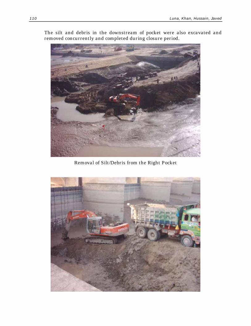
and downstream cofferdams in a limited time was in fact an activity lying on critical path. It was very essential to remove all these deposits to clear and expose the upstream and downstream floor for detailed inspection, subsurface investigations and to finalize the methodology for carrying out the repair works. As per programme the removal of sediment deposits was scheduled to be completed by end of February, 2005 starting from January 15, 2005. Taking cognizance of the situation, the demucking work was started within upstream cofferdam on December 15, 2004 from divide wall side by making ramp. Because of presence of thick layer of slush the excavators could not be deployed inside the pocket for removal of the huge quantity of the muck unless some special working arrangements were made. For this purpose a ramp was made with dry earth borrowed from the bela and it was dumped over the slushy area. At the end of ramp two pads were made for stationing of excavators. Two excavators were deployed for excavation of the slush/debris which was transported to the bela side by 25 No. tractor-driven trolleys. Five submersible pumps of 3 cusecs capacity and ten peter pumps were also used to bail out the surface water in the pocket to create dry conditions. The job was very cumbersome and time consuming. Quite a number of times the tractor/trolleys got stuck up and sank in the approach track because of slushy conditions. As the annual closure of canals was effected in January, the pocket area started drying up after piles were driven in the cofferdam. The work was carried out day and night. 42 No. flood lights were installed for the night work. The pocket gates were also opened during 2nd week of January 2005 to facilitate transportation of silt under the gates on downstream side through Bays No. 4 and 5. It was a gigantic and most difficult task which was successfully completed during 4th week of January, 2005 in a period of 6 weeks i.e. 4 weeks ahead of scheduled time. It was in fact a turning point in completion of the Project on schedule inspite of the fact that quantum of concreting work later increased by about 50%. This saving in time provided leverage to FWO for taking up and completing other activities ahead of scheduled time.
110 Luna, Khan, Hussain, Javed
The silt and debris in the downstream of pocket were also excavated and removed concurrently and completed during closure period.
Removal of Silt/Debris from the Right Pocket
Pakistan Engineering Congress, 70th Annual Session Proceedings 111
Removal of Silt/Debris from the Right Pocket
5.4 Dewatering of Working Area For surface and sub surface dewatering of the working area enclosed
by the cofferdams, following arrangements were made:
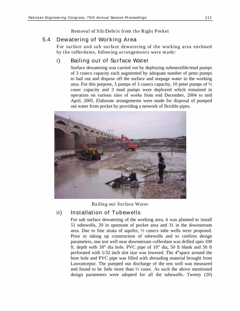
i) Bailing out of Surface Water Surface dewatering was carried out by deploying submersible/mud pumps
of 3 cusecs capacity each augmented by adequate number of peter pumps to bail out and dispose off the surface and seepage water in the working area. For this purpose, 5 pumps of 3 cusecs capacity, 10 peter pumps of ½ cusec capacity and 3 mud pumps were deployed which remained in operation on various sites of works from end December, 2004 to mid April, 2005. Elaborate arrangements were made for disposal of pumped out water from pocket by providing a network of flexible pipes.
Bailing out Surface Water
ii) Installation of Tubewells For sub surface dewatering of the working area, it was planned to install
51 tubewells, 20 in upstream of pocket area and 31 in the downstream area. Due to fine strata of aquifer, ½ cusecs tube wells were proposed. Prior to taking up construction of tubewells and to confirm design parameters, one test well near downstream cofferdam was drilled upto 100 ft. depth with 18” dia hole. PVC pipe of 10” dia, 50 ft blank and 50 ft perforated with 1/32 inch slot size was lowered. The 4”space around the bore hole and PVC pipe was filled with shrouding material brought from Lawrancepur. The pumped out discharge of the test well was measured and found to be little more than ½ cusec. As such the above mentioned design parameters were adopted for all the tubewells. Twenty (20)
112 Luna, Khan, Hussain, Javed
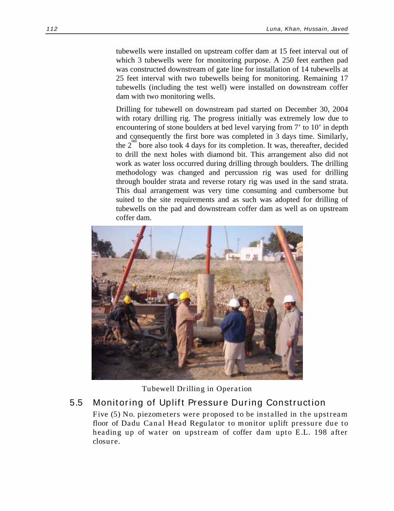
tubewells were installed on upstream coffer dam at 15 feet interval out of which 3 tubewells were for monitoring purpose. A 250 feet earthen pad was constructed downstream of gate line for installation of 14 tubewells at 25 feet interval with two tubewells being for monitoring. Remaining 17 tubewells (including the test well) were installed on downstream coffer dam with two monitoring wells.
Drilling for tubewell on downstream pad started on December 30, 2004 with rotary drilling rig. The progress initially was extremely low due to encountering of stone boulders at bed level varying from 7’ to 10’ in depth and consequently the first bore was completed in 3 days time. Similarly, the 2
nd bore also took 4 days for its completion. It was, thereafter, decided
to drill the next holes with diamond bit. This arrangement also did not work as water loss occurred during drilling through boulders. The drilling methodology was changed and percussion rig was used for drilling through boulder strata and reverse rotary rig was used in the sand strata. This dual arrangement was very time consuming and cumbersome but suited to the site requirements and as such was adopted for drilling of tubewells on the pad and downstream coffer dam as well as on upstream coffer dam.
Tubewell Drilling in Operation
5.5 Monitoring of Uplift Pressure During Construction Five (5) No. piezometers were proposed to be installed in the upstream
floor of Dadu Canal Head Regulator to monitor uplift pressure due to heading up of water on upstream of coffer dam upto E.L. 198 after closure.
Pakistan Engineering Congress, 70th Annual Session Proceedings 113
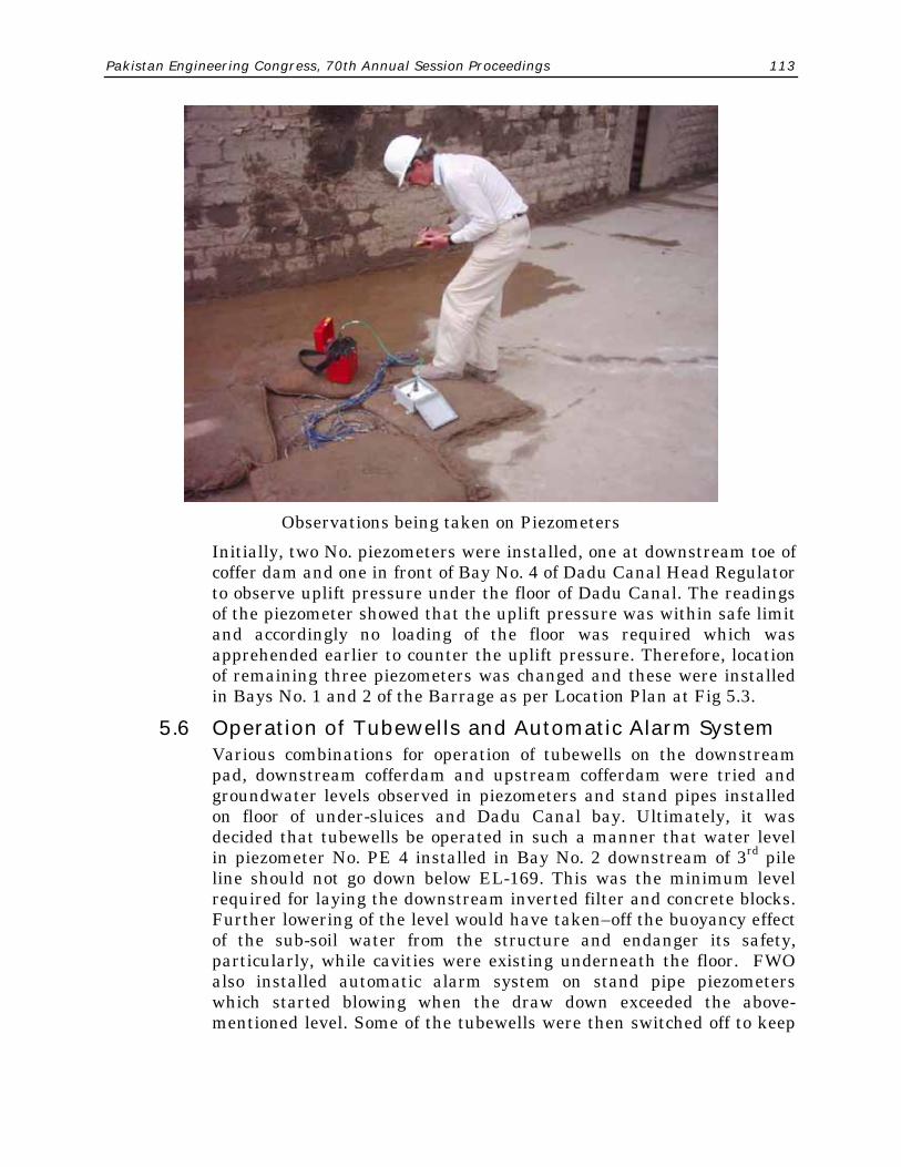
Observations being taken on Piezometers
Initially, two No. piezometers were installed, one at downstream toe of coffer dam and one in front of Bay No. 4 of Dadu Canal Head Regulator to observe uplift pressure under the floor of Dadu Canal. The readings of the piezometer showed that the uplift pressure was within safe limit and accordingly no loading of the floor was required which was apprehended earlier to counter the uplift pressure. Therefore, location of remaining three piezometers was changed and these were installed in Bays No. 1 and 2 of the Barrage as per Location Plan at Fig 5.3.
5.6 Operation of Tubewells and Automatic Alarm System Various combinations for operation of tubewells on the downstream
pad, downstream cofferdam and upstream cofferdam were tried and groundwater levels observed in piezometers and stand pipes installed on floor of under-sluices and Dadu Canal bay. Ultimately, it was decided that tubewells be operated in such a manner that water level in piezometer No. PE 4 installed in Bay No. 2 downstream of 3rd pile line should not go down below EL-169. This was the minimum level required for laying the downstream inverted filter and concrete blocks. Further lowering of the level would have taken–off the buoyancy effect of the sub-soil water from the structure and endanger its safety, particularly, while cavities were existing underneath the floor. FWO also installed automatic alarm system on stand pipe piezometers which started blowing when the draw down exceeded the above-mentioned level. Some of the tubewells were then switched off to keep

114 Luna, Khan, Hussain, Javed
the ground water level within safe limits. This arrangement worked very well and the groundwater was kept at permissible limit of E.L. 169.
Automatic Alarm System
5.7 Geophysical Investigations for Determination of Cavities
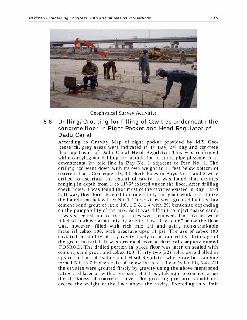
Geophysical investigations were conducted simultaneously through M/S Geo-Research, Sub-Contractor for geophysical investigations along with other investigations to find out the cavities under the floor. These investigations comprising Non-Destructive Evaluation (NDE) techniques of Gravity Method and Electric Resistivity Method, successfully conducted at Taunsa Barrage, were adopted at Sukkur Barrage. Before carrying out the investigations, the floor was made dry. Eight hundred and ninety-six (896) points were laid down on upstream and downstream floor of under-sluices and upstream floor of Dadu Canal Head Regulator for application of Gravity Method Technique. Similarly, 321 points were laid down on floors for carrying out Electric Resistivity Survey. Based on the results, Gravity Map was drawn for the right pocket. 38 locations were selected for drilling in view of existence of low density areas. Confirmatory check holes were drilled on the selected locations in order to verify the authenticity of investigations. About 80% of investigations work was found to be correct.
Pakistan Engineering Congress, 70th Annual Session Proceedings 115
Geophysical Survey Activities
5.8 Drilling/Grouting for Filling of Cavities underneath the concrete floor in Right Pocket and Head Regulator of Dadu Canal
According to Gravity Map of right pocket provided by M/S Geo-Research, grey areas were indicated in 1st Bay, 2nd Bay and concrete floor upstream of Dadu Canal Head Regulator. This was confirmed while carrying out drilling for installation of stand pipe piezometer at downstream 2nd pile line in Bay No. 1 adjacent to Pier No. 1. The drilling rod went down with its own weight to 11 feet below bottom of concrete floor. Consequently, 11 check holes in Bays No. 1 and 2 were drilled to ascertain the extent of cavity. It was found that cavities ranging in depth from 1’ to 11’-6” existed under the floor. After drilling check holes, it was found that most of the cavities existed in Bay 1 and 2. It was, therefore, decided to immediately carry out work to stabilize the foundation below Pier No. 1. The cavities were grouted by injecting cement sand grout of ratio 1:6, 1:5 & 1:4 with 2% bentonite depending on the pumpability of the mix. As it was difficult to inject coarse sand, it was screened and coarse particles were removed. The cavities were filled with above grout mix by gravity flow. The top 6” below the floor was, however, filled with rich mix 1:1 and using non-shrinkable material cebex 100, with pressure upto 11 psi. The use of cebex 100 obviated possibility of any cavity likely to be caused by shrinkage of the grout material. It was arranged from a chemical company named ‘FOSROC’. The drilled portion in pucca floor was later on sealed with cement, sand grout and cebex 100. Thirty two (32) holes were drilled in upstream floor of Dadu Canal Head Regulator where cavities ranging form 1.5 ft to 7 ft deep existed below the pucca floor (refer Fig 5.4). All the cavities were grouted firstly by gravity using the above mentioned ratios and later on with a pressure of 3-4 psi, taking into consideration the thickness of concrete above. The grouting pressure should not exceed the weight of the floor above the cavity. Exceeding this limit
116 Luna, Khan, Hussain, Javed
may lead to cracking of the floor. The total number of cement bags consumed in grouting were 6500 in bay No. 1 and 2 of the main weir and floor in front of Dadu Canal head regulator.
Two No. inclined holes at 45 degrees angle on slope portion in bay Nos. 1 and 2 of Dadu Canal head regulator were also drilled for depth of 16 ft. to check cavities below foundation of the Structure. No cavity was found therein. Later on, as per advice of Geo-technical Specialist and also to confirm the findings of Geo- Research, 25 holes were drilled in bay Nos. 1 to 5 of under-sluices upto 32 ft. depth and Standard Penetration Tests (SPTs) were carried out to confirm the density of foundation soil. In addition, 6 No. 5” dia bore holes upto depth of 9’ – 6” were drilled in bay Nos. 1 and 2 of under-sluices on advice of ATKINS to check the status and permeability of stone masonry/ concrete. After filling the holes with water, no substantial loss of water occurred upto 6 hours showing that masonry was in good shape. To check the runnels under the structure, 20 holes were drilled, spaced 15 ft. c/c and SPTs below the pucca floor were conducted, which confirmed presence of original river bed material and no loose material was confronted. This confirmed that no runnel had crossed the structure. The phenomenon of sinking of piles on upstream coffer dam could be attributed to local scour.
5.9 Treatment of Scour Pit Treatment of the pit was one of the most critical activities because of
its proximity with the main structure and especially Pier No. 1, which was just hanging over the cavity underneath on its upstream side. Various proposals as summarized below were discussed with the Client, Specialist on drilling and grouting, and the Contractors :
i) Top of the pit be shot-creted and then drilling be carried out for injection of cement grout in between the stone filled in the pit.
ii) Top layer of slush in the pit be removed only upto 4-5 feet and refilled with sand; and reinforced cement concrete be provided to avoid subsequent settlement.
iii) Sand piling method was also considered as one of the option to stabilize the soil.
iv) New pavement with ground beam be provided. After discussions and deliberations with experts, none of the above
proposals was found appealing and technically viable. It was, therefore, decided that unless whole of the slush along with filled stone and broken concrete slab in the pit was removed and refilled with stabilized soil, the problem was not going to be addressed properly. Removal of silt and stones etc. from the pit in front of Pier No. 1 nose was itself a very tricky job, because its removal near the foundation could cause sucking of the soil from underneath and further settlement/damage to Pier No. 1. However, after careful consideration

Pakistan Engineering Congress, 70th Annual Session Proceedings 117
of the situation, following methodology for removal of slush and stones from the pit was adopted which proved to be very effective and successful.
• The cavity around Pier No. 1 was filled with cement-sand grout to stabilize the foundation below the pier.
• Operation for excavation of the pit was started from Bay No. 4. The settled concrete floor in Bay No. 4 was first broken and concrete taken out. Bolari coarse sand was filled in length of about 15 feet to provide stable base for working of excavator. Local sand, being fine, was not suited to make a good foundation.
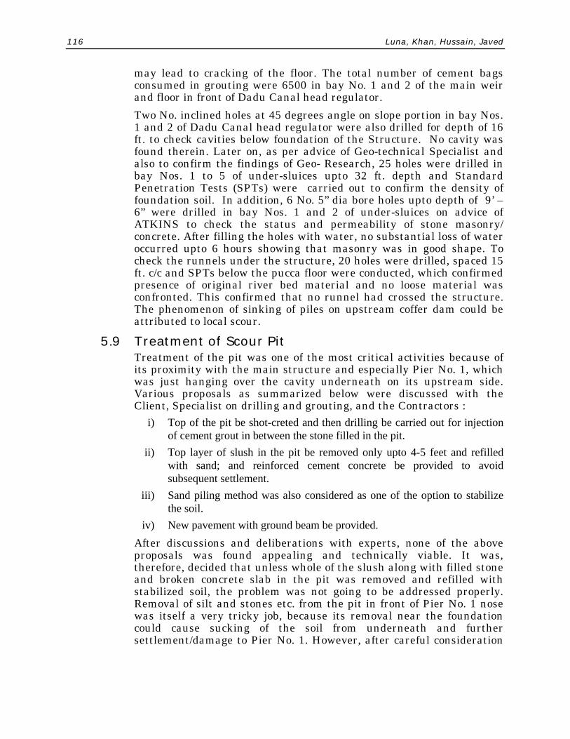
• Further excavation of the pit and removal of slush and broken concrete slab from the pit upto natural bed level was carried out and refilling done with compacted coarse Bolari sand simultaneously. The filled coarse sand was compacted to provide stable foundation for the concrete floor subsequently laid over it. The following photographs show different stages of pit treatment.
Sand Filling and Compaction at a Glance
118 Luna, Khan, Hussain, Javed

Pakistan Engineering Congress, 70th Annual Session Proceedings 119
Sand Filling and Compaction at a Glance
5.10 Treatment to Upstream Floor of Dadu Canal While carrying out filling of the pit and driving of additional sheet
piles upstream of Dadu Canal floor, a crack developed all along the floor 5 feet from the old sheet pile. Cavities were also noticed under 5 feet cantilever portion of concrete floor beyond the sheet pile. The last 10 feet of concrete floor upto Pier No. 3 were therefore dismantled. Examination of the remaining floor revealed that, inspite of grouting a number of holes at close spacing in the floor, some cavities still existed. One diagonal crack also appeared starting from end of floor opposite Pier No. 3 and extending upto left abutment. The crack was opened to check its extent. It was found that crack travelled right through the stone masonry. After careful consideration and discussion with the Client, it was decided to dismantle the concrete floor completely and to relay it. Only 15.0 feet strip along the toe of upstream glacis was left to give support to the structure.
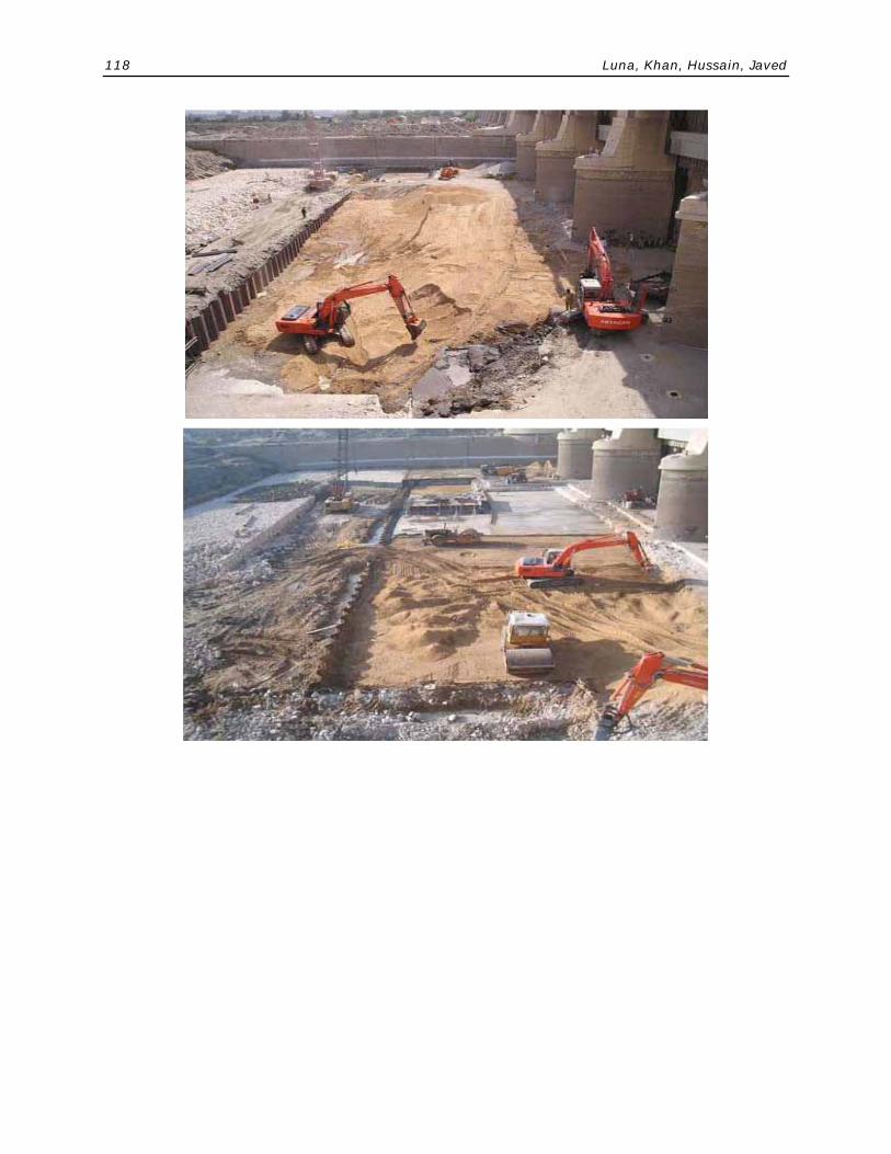
5.11 Sheet Piling i) Sheet Piling at Upstream End of Extended Floor: A new line of sheet
piles was driven at the upstream end of the extended floor in the right pocket. These sheet piles were driven to different levels (depth below top of floor varying from 17 feet to 30 feet) below the floor upto firm strata which was encountered below E.L 159.0. Reinforced pile capping was provided for proper anchorage. This cap was not provided in the earlier design.
120 Luna, Khan, Hussain, Javed
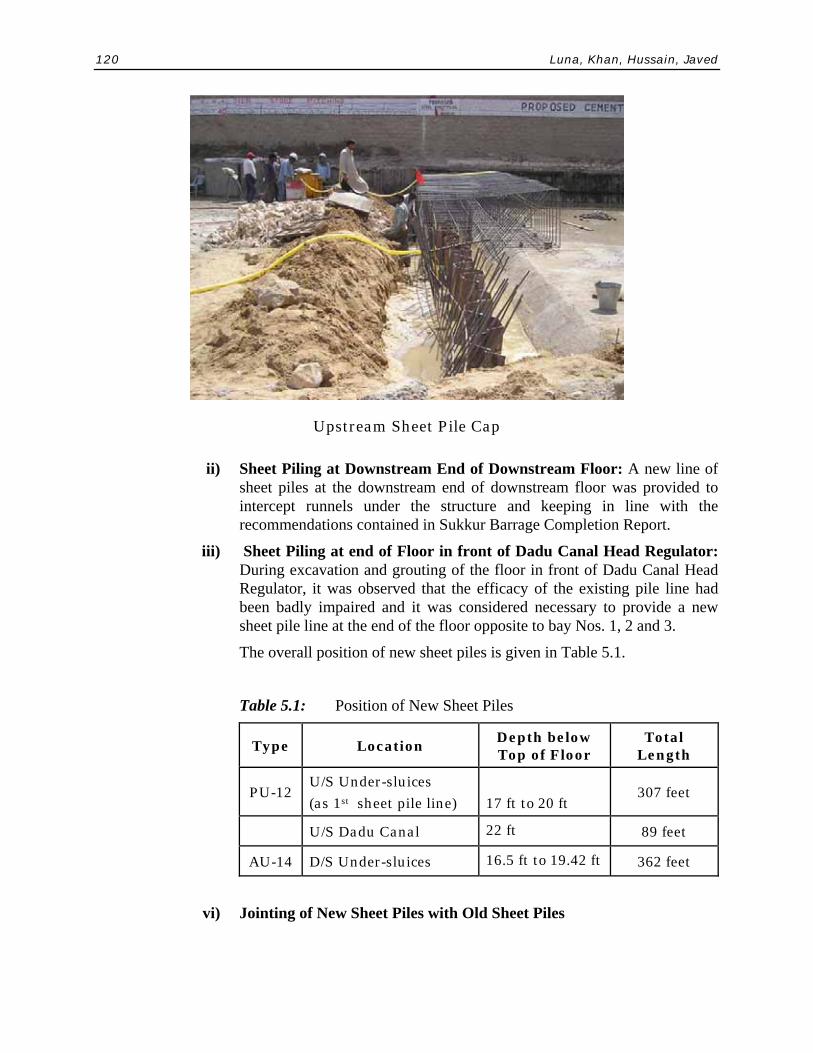
Upstream Sheet Pile Cap
ii) Sheet Piling at Downstream End of Downstream Floor: A new line of sheet piles at the downstream end of downstream floor was provided to intercept runnels under the structure and keeping in line with the recommendations contained in Sukkur Barrage Completion Report.
iii) Sheet Piling at end of Floor in front of Dadu Canal Head Regulator: During excavation and grouting of the floor in front of Dadu Canal Head Regulator, it was observed that the efficacy of the existing pile line had been badly impaired and it was considered necessary to provide a new sheet pile line at the end of the floor opposite to bay Nos. 1, 2 and 3.
The overall position of new sheet piles is given in Table 5.1.
Table 5.1: Position of New Sheet Piles
Type Location Depth below Top of Floor
Total Length
PU-12 U/S Under-sluices (as 1st sheet pile line)
17 ft to 20 ft
307 feet
U/S Dadu Canal 22 ft 89 feet
AU-14 D/S Under-sluices 16.5 ft to 19.42 ft 362 feet
vi) Jointing of New Sheet Piles with Old Sheet Piles
Pakistan Engineering Congress, 70th Annual Session Proceedings 121
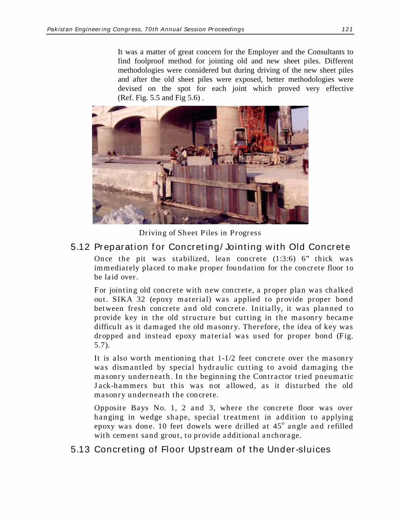
It was a matter of great concern for the Employer and the Consultants to find foolproof method for jointing old and new sheet piles. Different methodologies were considered but during driving of the new sheet piles and after the old sheet piles were exposed, better methodologies were devised on the spot for each joint which proved very effective (Ref. Fig. 5.5 and Fig 5.6) .
Driving of Sheet Piles in Progress
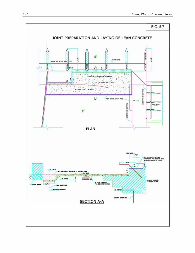
5.12 Preparation for Concreting/Jointing with Old Concrete Once the pit was stabilized, lean concrete (1:3:6) 6” thick was
immediately placed to make proper foundation for the concrete floor to be laid over.
For jointing old concrete with new concrete, a proper plan was chalked out. SIKA 32 (epoxy material) was applied to provide proper bond between fresh concrete and old concrete. Initially, it was planned to provide key in the old structure but cutting in the masonry became difficult as it damaged the old masonry. Therefore, the idea of key was dropped and instead epoxy material was used for proper bond (Fig. 5.7).
It is also worth mentioning that 1-1/2 feet concrete over the masonry was dismantled by special hydraulic cutting to avoid damaging the masonry underneath. In the beginning the Contractor tried pneumatic Jack-hammers but this was not allowed, as it disturbed the old masonry underneath the concrete.
Opposite Bays No. 1, 2 and 3, where the concrete floor was over hanging in wedge shape, special treatment in addition to applying epoxy was done. 10 feet dowels were drilled at 45o angle and refilled with cement sand grout, to provide additional anchorage.
5.13 Concreting of Floor Upstream of the Under-sluices

122 Luna, Khan, Hussain, Javed
The concreting of the extended upstream floor was done in alternate panels. Due to huge volume, concrete pumps and admixture/ super plasticizer (Sika-520) were used to increase setting time and improve workability and to avoid cold joints. By using super plasticizer, water-cement (W.C) ratio could be reduced from 0.45 to 0.40 which improved compression strength of concrete by about 15%.
A four thousand (4000) psi concrete was used and strict laboratory control was exercised by taking concrete samples in cylinders at regular intervals and slump was also taken frequently. Double water stoppers were provided to safeguard against possible leakage through the joints.
A View of New Concrete Floor after Rehabilitation
5.14 Upstream Settling Blocks In the original design, only stone apron 6.0 feet thick was provided on
upstream side in a length of 50 feet. After the damage, it was considered necessary to provide heavy concrete blocks which could counter swirling action immediately upstream of the concrete floor. Settling blocks 4’x4’x4’ were specially manufactured and placed upstream of the concrete floor in a length of 40 feet over 2.0 feet stone apron. No space was left in between the blocks. These blocks were casted in a separate yard using sulphate resisting cement and Sekament 163 as accelerating agent for quick setting. The compressive strength was kept as 3000 psi. The strength was checked frequently to monitor quality.

Pakistan Engineering Congress, 70th Annual Session Proceedings 123
Placing of Blocks Upstream of Barrage
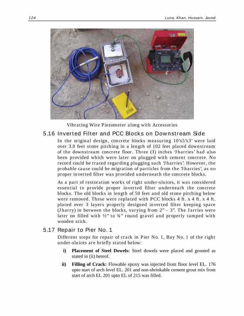
5.15 Installation of Remaining Piezometers The electronic type piezometers equipment comprised vibrating wire
piezometer and associated cabling, terminal unit and readout unit. The piezometers were imported from Geokon (USA). Later on during April, 2005, 24 No. additional vibrating wire piezometers were installed in the under-sluices of right pocket by M/s ATKINS in order to monitor on regular basis the uplift pressures in the under-sluices and upstream and downstream of Dadu Canal Head Regulator. The performance and adequacy of emergent works during operation of the Barrage would also be monitored with piezometer readings.
The procedure for installation of piezometers consisted of drilling of 2” dia holes with rotary core drilling machine extending beneath the pucca floor to a depth of about 6-7 ft. depending upon the strata. The drilled material was recovered for analysis of strata. Standard penetration tests (SPTs) were also carried out for each piezometer location. When the hole was advanced to the required depth, the piezometer was lowered into the hole with the cable extending upto the top of hole for subsequent connection with the terminal unit. Thereafter, the bore hole casing was slowly withdrawn with filling of sand of uniform grading (500-1200) micron. The hole was filled within 4-6 inch of the under side of the floor. Then 1:1 bentonite cement grout upto underside of the floor was filled. Thereafter, the pucca floor was filled upto the top with non shrinkable grout consisting of cement sand and Cebex 100. The piezometer details are given in Fig. 5.8.
124 Luna, Khan, Hussain, Javed
Vibrating Wire Piezometer along with Accessories
5.16 Inverted Filter and PCC Blocks on Downstream Side In the original design, concrete blocks measuring 10’x5’x3’ were laid
over 3.0 feet stone pitching in a length of 102 feet placed downstream of the downstream concrete floor. Three (3) inches ‘Jharries’ had also been provided which were later on plugged with cement concrete. No record could be traced regarding plugging such ‘Jharries’. However, the probable cause could be migration of particles from the ‘Jharries’, as no proper inverted filter was provided underneath the concrete blocks.
As a part of restoration works of right under-sluices, it was considered essential to provide proper inverted filter underneath the concrete blocks. The old blocks in length of 50 feet and old stone pitching below were removed. These were replaced with PCC blocks 4 ft. x 4 ft. x 4 ft. placed over 3 layers properly designed inverted filter keeping space (Jharry) in between the blocks, varying from 2” – 3”. The Jarries were later on filled with ½” to ¾” round gravel and properly tamped with wooden stick.
5.17 Repair to Pier No. 1 Different steps for repair of crack in Pier No. 1, Bay No. 1 of the right
under-sluices are briefly stated below: i) Placement of Steel Dowels: Steel dowels were placed and grouted as
stated in (ii) hereof.
ii) Filling of Crack: Flowable epoxy was injected from floor level EL. 176 upto start of arch level EL. 201 and non-shrinkable cement grout mix from start of arch EL 201 upto EL of 215 was filled.

Pakistan Engineering Congress, 70th Annual Session Proceedings 125
iii) Horizontal and Vertical Control for Dowel Positions: Slope of core hole, 1:50, was measured with the help of mason’s level, on the machine. Horizontal position was controlled at 45o, measurable from the machine mechanism.
5.18 Construction of Downstream Cut off Wall The cut off wall was cast at site with its bottom at EL-165. As per
drawing, the thickness of cut-off was 2.0 ft. However, during execution, due to difficulty in fixing the shuttering, the width of cut off wall in the bottom 4.0 ft. depth was increased to 3.5 ft. and was kept as 2.0 ft in the remaining height.
5.19 Reconstructing Upstream Stone Apron The stone apron in 6 ft depth and 60 ft. length placed upstream of
extended concrete floor was re-constructed with proper size stone. Similarly, stone apron downstream of the settling blocks placed over inverted filter was replenished to design depth of 6.0 feet.
Upstream Stone Apron
5.20 Removal of Upstream and Downstream Cofferdams
and Tubewells

126 Luna, Khan, Hussain, Javed
After completion of emergent works, during end April 2005, Consultants devised a methodology for removal of upstream & downstream cofferdams and dismantling of tubwells in a well planned manner so as not to cause any negative impact on the works. For this purpose, the following sequence of operations was followed:
5.20.1 Removal of Downstream Pad The activities were conducted sequentially as follows: i) Removal of
tubewells machinery ii) Filling of bore holes with shrouding material iii) Removal of earth work of pad and disposal to outside of the Project area.
5.20.2 Removal of Downstream Cofferdam The activities were carried out in the following order: i) Removal of gunny
bags from upstream and downstream slopes of the cofferdam. ii) Removal of gunny bags apron on the upstream side. iii) Removal of tubewell machinery and thereafter filling of bore holes with river bed material. iv) Extraction of sheet piles. v) Removal of earthwork of coffer dam after removal of the stone apron on the downstream side upto design level.
5.20.3 Removal of Upstream Cofferdam After removal of downstream cofferdam and the pad, the river water from
downstream side was allowed to enter the right pocket and downstream of the cofferdam to rise upto downstream river water level. Following operations thereafter were carried out in the given sequence.
i) Removal of tubewell machinery and refilling the bore holes with river bed material upto EL-202.
ii) Removal of upstream gunny bags apron starting from Dadu Canal regulator side.
iii) Removal of gunny bags apron upstream of the cofferdam in the remaining length.
iv) Extraction of sheet piles starting from the right side of Dadu Canal Regulator.
v) Removal of earth work of coffer dam by dredging including removal of the remaining bela upstream of the coffer dam.
While carrying out the above mentioned operations, it was ensured that no obstruction on the river bed/floor in the shape of earth heaps, stone material or gunny bags was left in the pocket as well as in the under-sluices because such obstructions would cause adverse effect on the functioning of the under-sluices.
All the above operations were taken up during Ist week of May, 2005. Two cuts in upstream cofferdam were made on May 21, 2005 in presence of DG FWO which marked the start of ponding of right pocket.

Pakistan Engineering Congress, 70th Annual Session Proceedings 127
6. CAUSE OF DAMAGE 6.1 General As a result of preliminary investigations by Technical/Advisory
Committee, Government of Sindh and Dam Safety Organization, WAPDA, it was postulated that swirl formation caused by adverse hydraulic conditions of flow in the right pocket of the Barrage triggered scour phenomena in the stone apron in front of bay Nos. 1, 2 and 3 which eventually led to collapse of the upstream pile line and the concrete floor. The Consultants carried out study of the cause of damage as a part of their assignment. They reviewed the previous reports and related data on the subject particularly that prepared after the damage was noticed in 2004. These reports/data, inter-alia, included: report of Technical/Advisory Committee of Senior Engineers constituted by the Government of Sindh in February 2004; Publication No. 802 (July, 2004) issued by Dam Safety Organization (DSO), WAPDA, record of the gauges, sounding plans, state of bela formation in the pockets, the mode of scouring operations and regulation practices. The Consultants also conducted detailed examination of the damage during dry conditions and carried out hydraulic analysis of the structure for surface and sub-surface flow conditions. The findings of the Study were confirmed on the physical model operated at Nandipur Research Station. The details of the study and conclusions drawn are given in the following paras.
6.2 Cause of Damage The detailed scrutiny of the related record, regulation and
maintenance practices at the Barrage, particularly that for the right pocket, appraisal of surface and sub-surface flow conditions, and confirmatory model study carried out at the Hydraulic Research Station Nandipur have led to following conclusions regarding the cause of the damage at Sukkur Barrage.
i) Still pond system of regulation at Sukkur Barrage caused sediment deposits in the pocket which could not be cleared due to inadequate flushing operations through the pockets. As a result heavy bela formation in the right pocket caused drastic reduction in the available water-way from about 350 feet to 70 feet leading to sharp increase in discharge intensity during passage of high floods when the under-sluices were opened.

128 Luna, Khan, Hussain, Javed
View of Bela in Right Pocket before Emergency works
ii) The uneven opening of gates during flushing operations induced vertical rollers and bed velocities ranging from 16’ to 20’/second as observed on the Model. On occasions, the flushing gates were opened 14’ to 16’, while the adjoining gates were opened 6’ to 8’ or closed. The high velocity flow from the restricted water way (only 70 ft.) would strike against the closed/almost closed gates, rise vertically against the gates and flow upstream and the turn towards the wide open gates Nos. 4 & 5 causing a severe swirling action near the bed. These abnormal hydraulic conditions triggered scour phenomena in the stone apron upstream of the concrete floor in the right pocket.
iii) The scouring action accentuated with enlargement of the scour pit and roller action in the cavity area which progressively extended upto and below the first line of sheet piles and to the concrete floor in front of bay Nos. 2 and 3.
iv) Though these developments must have taken some years to occur yet these were discovered/reported while observing soundings in the pocket during the closure of year 2004. The cross-sections of the right pocket show that the scour pit was first formed during the year 2002 which progressively enlarged and assumed alarming proportions in the year 2004.
7. REMEDIAL MEASURES FOR FUTURE SAFETY The recurrence of damages of the type that occurred in the right pocket
during 2004 can be checked by adopting the following two categories of measures for operation and maintenance of the Barrage.
Pakistan Engineering Congress, 70th Annual Session Proceedings 129
7.1 Special Flushing Measures i) As concluded above, formation of large belas in the pockets causing
drastic reduction of the available water-way should not be allowed. For this purpose the two pockets must be kept clear of sediment deposits as far as possible by carrying out flushing operations as and when required as per guidelines laid out in the regulation rules. Since frequent flushing closure of the canals is not admissible in the peculiar conditions of the areas served by the canals at Sukkur Barrage, special arrangements must be made for dredging of the pockets on regular basis. For this purpose, the Sindh Irrigation Department must arrange dredgers for dredging pockets of the Barrage and any other untoward shoal formations at sensitive locations elsewhere at the Barrage. A plan showing the areas to be kept clear of sediment deposits by flushing and dredging on an annual basis is enclosed as Figure 7.1. This plan can be modified based on the operational experiences in future and should be approved by the Chief Engineer Incharge of the Barrage.
ii) Large variations in the opening of adjoining gates during flushing operations which lead to formation of vertical rollers and generation of high bed velocities should not be allowed: The guidelines given in the operation and maintenance manual must be followed meticulously for operation of the Barrage. Any departure from the rules under abnormal conditions must be with the approval of the competent authority and under the personal supervision of the engineers incharge of the Barrage as laid down in the regulation rules. In order to counteract against high bed velocities and formation of scour pits, a flexible block apron has been added in the right pocket upstream of the first sheet pile line in a length of 40 feet. These heavy bocks (4’x4’x4’) cannot be lifted by high bed velocities and will protect the upstream sheet pile line against any scouring action.
7.3 Regular Maintenance Measures The following operational and maintenance procedures have been
proposed to minimize the chances of recurrence of damages in the two pockets and main weir of the Barrage:
i) History of Head works and Annual Headworks Reports must be prepared by regular inspections and periodic observations of soundings and probings at the Barrage. These documents must be prepared as per time schedule and submitted to the authorities concerned for appropriate decisions and timely remedial measures as required.
ii) Observation and maintenance of all the headworks record including, gauges, gate openings on proper log books and registers as per departmental procedures must be ensured. Vibrating wire piezometers are

130 Luna, Khan, Hussain, Javed
being installed at the Barrage. The record of uplift pressures must be maintained for monitoring foundation conditions of the Barrage.
iii) Hydraulic and Sediment Testing Laboratory must be re-established. Elaborate and fool-proof arrangements must be ensured for sediment sampling from the pockets and off-taking canals to monitor the sediment movement/deposit upstream of the pockets and into the canals.
iv) The practice of conducting morphological surveys upstream and downstream of the Barrage seems to have been stopped. These surveys must be annually carried out and detailed river survey plans prepared. These are essential to keep a watch on the river behaviour and are of tremendous help in preparation of future improvement plans.
v) No arrangement exists in both the pockets of the Barrage for carrying out observations of soundings/probings in the flowing river. The Consultants have designed and prepared a proposal for implementation for this purpose which should be carried out.
vi) The officers and Sub-Engineers posted at the Barrage should be suitably selected on the basis of their competence, experience and temperament for the relevant field. Most of the deterioration of the vital structures has resulted from in-apt staff which do not know the subject and shy away from their responsibilities.
vii) Besides observing the general operation and maintenance procedures for maintenance and operation of the Barrage the Engineer Incharge should keep a watch on development of any unusual situation and should promptly take adequate necessary action for keeping the things under control.
viii) None of the essential maintenance, repair or replenishing works required should be deferred and the authorities should ensure availability of essential required finances.

Pakistan Engineering Congress, 70th Annual Session Proceedings 131

132 Luna, Khan, Hussain, Javed

Pakistan Engineering Congress, 70th Annual Session Proceedings 133
134 Luna, Khan, Hussain, Javed
Pakistan Engineering Congress, 70th Annual Session Proceedings 135

136 Luna, Khan, Hussain, Javed

Pakistan Engineering Congress, 70th Annual Session Proceedings 137

138 Luna, Khan, Hussain, Javed

Pakistan Engineering Congress, 70th Annual Session Proceedings 139
140 Luna, Khan, Hussain, Javed

Pakistan Engineering Congress, 70th Annual Session Proceedings 141

142 Luna, Khan, Hussain, Javed

Pakistan Engineering Congress, 70th Annual Session Proceedings 143