csl manual - fanatec · thank you for choosing to get the most out of and before using your new csl...
TRANSCRIPT

Manual
www.fanatec.com

Thank you for choosing
To get the most out of and before using your new CSL Elite Pedals and the CSL Elite Pedals Loadcell Kit, please read this manual for important information regarding your health and how to safely use this product. This manual can also be used as a great tool for future reference.

3
INDEX1. General ............................................................................................................... 5-6
2. Introduction ........................................................................................................ 7
3. Compatibility ....................................................................................................... 8
4. Preparation ......................................................................................................... 9-124.1 Package content CSL Elite Pedals ............................................................. 9-104.2 Part list CSL Elite Pedals ............................................................................ 104.3 Package content CSL Elite Pedals Loadcell Kit........................................ 114.4 Part list CSL Elite Pedals Loadcell Kit ....................................................... 12
5. Assembly ............................................................................................................. 13-265.1 Plan your configuration .............................................................................. 135.2 Mounting the the CSL Elite Pedals ............................................................. 14-155.3 Mounting the CSL Elite Pedals LC ............................................................. 16-185.4 Stabilizer bars (recommendation) .............................................................. 19-205.5 Hardmounting the CSL Elite Pedals and/or CSL Elite Pedals LC ........... 20-215.6 Attaching / detaching the pedal plate rubber covers ............................... 225.7 Attaching anti-skid pads ............................................................................. 22-235.8 Connections CSL Elite Pedals .................................................................... 245.9 Connections CSL Elite Pedals LC .............................................................. 25-26
6. Functions & Features ......................................................................................... 27-386.1 PC driver software ....................................................................................... 27-326.2 Firmware and driver update ........................................................................ 32-356.3 Pedal auto calibration mode ....................................................................... 366.4 Pedal manual calibration ............................................................................ 36-38
7. Electronic operation ........................................................................................... 397.1 Hotkeys ......................................................................................................... 39
8. Cleaning .............................................................................................................. 40
9. Maintenance ........................................................................................................ 40
10. Troubleshooting ............................................................................................... 41-42
11. Serial number ..................................................................................................... 43
12. Trademarks ........................................................................................................ 43
13. Ecology Advice .................................................................................................. 44
14. FCC Compliance ................................................................................................ 45
15. CE Compliance .................................................................................................. 45
16. Warranty ............................................................................................................. 46

4
WARNING! Photosensitive Seizures
A very small percentage of people may experience a seizure when exposed to certain visual im- ages, including flashing lights or patterns that may appear in video games. Even people who have no history of seizures or epilepsy may have an undiagnosed condition that can cause these „pho- tosensitive epileptic seizures” while watching video games. These seizures may have a variety of symptoms, including light-headedness, altered vision, eye or face twitching, jerking or shaking of arms or legs, disorientation, confusion, or momentary loss of awareness. Seizures may also cause loss of consciousness or convulsions that can lead to injury from falling down or striking nearby objects. Immediately stop playing and consult a doctor if you experience any of these symptoms. Parents should watch for or ask their children about the above symptoms – children and teenagers are more likely than adults to experience these seizures.
The risk of photosensitive epileptic seizures may be reduced by taking the following precautions:• Sit farther from the TV screen.• Use a smaller TV screen.• Play in a well-lit room.• Do not play when you are drowsy or fatigued.
If you or any of your relatives have a history of seizures or epilepsy, consult a doctor before play- ing.
WARNING! Musculoskeletal disorders
Use of game controllers, keyboards, mice, or other electronic input devices may be linked to seri- ous injuries or disorders. When playing video games, as with many activities, you may experience occasional discomfort in your hands, arms, shoulders, neck, or other parts of your body. However, if you experience symptoms such as persistent or recurring discomfort, pain, throbbing, aching, tingling, numbness, burning sensation, or stiffness, DO NOT IGNORE THESE WARNING SIGNS. PROMPTLY SEE A QUALIFIED HEALTH PROFESSIONAL, even if symptoms occur when you are not playing a video game. Symptoms such as these can be associated with painful and some- times permanently disabling injuries or disorders of the nerves, muscles, tendons, blood vessels, and other parts of the body. These musculoskeletal disorders (MSDs) include carpal tunnel syn- drome, tendonitis, tenosynovitis, vibration syndromes, and other conditions.
While researchers are not yet able to answer many questions about MSDs, there is general agreement that many factors may be linked to their occurrence, including medical and physical conditions, stress and how one copes with it, overall health, and how a person positions and uses their body during work and other activities (including playing a video game). Some studies suggest that the amount of time a person performs an activity may also be a factor. If you have questions about how your own lifestyle, activities, or medical or physical condition may be related to MSDs, see a qualified health professional.

5
ATTENTION• The device must not be exposed to rain or humidity in order to avoid risk of fire and the danger
of electric shock.• Operating temperature: 15°C – 35°C room temperature• Long playing may cause health risks. Take a break of 5 minutes every 20 minutes, and do not
play for more than 2 hours per day.• We strongly advise you to not drive a vehicle immediately after using a video game.• Utilization of the vibration and Force Feedback function may cause damage to your health.• In case of interference with other wireless 2.4 GHz devices, the interfering devices must be
removed or switched off.• Not intended for children under the age of 6 years. Contains small pieces. Danger of swallowing!• Do not open the casing of the device.• This device contains components that cannot be repaired by the user, opening will void the
warranty.
WARNING! Electrical Safety
The CSL Elite Pedals and/or the CSL Elite Pedals LC must be connected to an appropriate power source:• For the used CSL Elite Pedals and CSL Elite Pedals LC use only the cords that came with your
CSL Elite Pedals and/or with the CSL Elite Pedals Loadcell Kit or that you received from an authorized repair center.
• For the used CSL Elite Pedals or CSL Elite Pedals LC do not use non-standard power sources, such as generators or inverters, even if the voltage and frequency appear acceptable. Only use power provided by PC USB port or wheel base port ‘Pedals’. To avoid damaging the CSL Elite Pedals LC:
� Do not try to use the CSL Elite Pedals and/or CSL Elite Pedals LC with cords different from the cords packaged with the CSL Elite Pedals and/or with the CSL Elite Pedals Loadcell Kit or received from authorized repair center.
� Unplug the power cord of your wheel base or disconnect the supply cord from CSL Elite Pedals and/or CSL Elite Pedals LC to PC USB port during storms or when unused for long periods of time to protect also your CSL Elite Pedals and/or CSL Elite Pedals LC.
� If the CSL Elite Pedals and/or CSL Elite Pedals LC become damaged in any way, stop using it immediately and contact Fanatec Customer Support
GENERAL1

6
GENERAL NOTES• CSL Elite Pedals and CSL Elite Pedals Loadcell Kit are both separately packed and sold
products. The CSL Elite Pedals Loadcell Kit is an add-on product which upgrades the basic CSL Elite Pedals to the CSL Elite Pedals LC. The basic CSL Elite Pedals are a mandatory requirement to operate the CSL Elite Pedals Loadcell Kit, the CSL Elite Pedals Loadcell Kit cannot be used without the basic CSL Elite Pedals.
• Additional peripheral devices like the Fanatec wheel bases, the ClubSport Handbrake and others which might be mentioned in this manual are not included within the CSL Elite Pedals and/or CSL Elite Pedals Loadcell Kit packages and sold separately.
• This manual explains a lot about assembly, connections and functions related to Fanatec wheel bases, other additional peripheral devices and also about PC or console functionalities but this manual is not a replacement for the manuals corresponding to the products! Read the quick guides or user manuals for the other products as well!
• All specifications in this document are subject to change. Especially the CSL Elite Pedals LC firmware, the wheel base firmware, the CS USB Adapter firmware or the PC driver might be changed or updated to implement new features or for general improvements.
• The warranty does not include defects that are due to commercial use of the product. See chapter “Warranty” at the end of this user manual as well as the terms & conditions on www.fanatec.com for more details.
• Technical copying partially or full product and reverse engineering is explicitly prohibited! Violation might have legal consequences

7
INTRODUCTION
The CSL Elite Pedals are an all new and innovative pedal set which offer a brake pedal, a throttle pedal and a heel rest made from solid metal.
The CSL Elite Pedals can be connected to Fanatec Wheel Bases like the CSL Elite Wheel Base or the ClubSport Wheel Bases and is immediately compatible to PC and consoles (please check the compatibility descriptions of your used Wheel Base for more details). Beyond that the CSL Elite Pedals can be con-nected to the ClubSport USB Adapter to establish a direct connection to PCs independent from the used Wheel Base or wheel.
The CSL Elite Pedals Loadcell Kit is an upgrade-product for the CSL Elite Ped-als which add a loadcell brake and make the original brake becoming the new clutch pedal. The loadcell brake provides a wide range of adjustment possibili-ties on hardware as well as on software side.
On top the Loadcell Kit comes with an own electronics module adding an USB to PC connection port as well as a handbrake connection port to the pedal sys-tem - of course the CSL Elite Pedals LC can stil be connected to Wheel Bases and wheels.
2
8
COMPATIBILITY
The CSL Elite Pedals can be used with the CSL Elite Wheel Base, the Club-Sport Wheel Base, the ClubSport Wheel Base V2, ClubSport USB Adapter and other peripheral devices from the Fanatec ClubSport and CSL platform!
The CSL Elite Pedals can be used on PC USB port only by a ClubSport USB Adapter or by wheel base connection (wheel base to be connected to PC USB port) and consoles (only by connection to wheel base, please check the com-patibility descriptions of the used Wheel Base for more details about PC and consoles compatibility).
The CSL Elite Pedals LC can be used with the CSL Elite Wheel Base, the ClubSport Wheel Base, the ClubSport Wheel Base V2, ClubSport Handbrake and other peripheral devices from the Fanatec ClubSport and CSL platform!
The CSL Elite Pedals can be used on PC USB port directly or by wheel base connection (wheel base to be connected to PC USB port) and consoles (only by connection to wheel base, please check the compatibility descriptions of the used Wheel Base for more details about PC and consoles compatibility).
IMPORTANT: Before first use the CSL Elite Pedals LC must be up-dated to the latest firmware version which is available on our website www.fanatec.com/support. See chapter ‘Firmware and driver update’ for more details! Also the firmware of your Fanatec wheel base and the PC driver must be updated to the latest versions available on our website www.fanatec.com/downloads.
3

9
PREPARATION
4.1 Package content CSL Elite Pedals
4
Heel rest
Pedal unit brake with rubber pedal covers
Pedal unit gas with rubber pedal covers
Slot cover

10
4.2 Part list CSL Elite Pedals
Part number Part name usage Picture Description
S1 ScrewM8 x 30 mm
4 Screw to mount the throttle pedal unit and/or brake pedal unit to the heel rest
N1 Self-securinghexagon nut M8
4 Nut to counter and tighten screws S1
W1 WasherID = 8 mm
8 Washers to be added onto screw S1
RJ12 cable
Allen Key 6 mm
Mounting screws, nuts and washers
Cropped wrench 13 mm
Quick Guide

11
4.3 Package content CSL Elite Pedals Loadcell Kit
CSL Elite Pedals LC electronics module
Pedal unit loadcell brake with rubber pedal cover
Allen Key 2 mm
USB cable
Clutch limiter pad
3x Anti-skid stickers for pedal plates
5x Elastomer spring shore 65 (pre-assembled, soft)
5x Elastomer spring shore 85 (medium)
5x Elastomer spring shore 95 (hard)
Quick Guide
Mounting screws, nuts and washers
Stabilizer bars with spacers

12
4.4 Part list CSL Elite Pedals Loadcell Kit
Part number Part name usage Picture Description
S1 ScrewM8 x 30 mm
2 Screw to mount the loadcell brake pedal unit to the heel rest
S2 Stabilizer barM8 x 250 mm
2 Stabilizer bars for reinforcement
N1 Self-securinghexagon nut M8
6 Nut to counter and tighten screws S1 (2 pcs.) and S2 (4 pcs.)
W1 WasherID = 8 mm
8 Washers to be added onto screw S1 (4 pcs.) and onto S2 (4 pcs)
E1 SpacerID = 6 mm
16 Spacers to be added onto stabilizer bars S2

13
ASSEMBLY
5.1 Plan your configurationFirst decide which pedals you will use, CSL Elite Pedals or CSL Elite Pedals LC. This decision leads into consequences for the next steps.
Then decide which way you want to connect the pedals, to wheel base or to PC USB port. This also needs to consider at which platform you want to use the pedals:
Option 1: Connect your CSL Elite Pedals or CSL Elite Pedals LC to the PC USB port. For CSL Elite Pedals you need the (optional) ClubSport USB Adapt-er, for CSL Elite Pedals LC the USB connection cable is included in CSL Elite Pedals Loadcell Kit package. This option is applicable only for use with PC, not applicable for use with consoles.
Option 2: Connect your CSL Elite Pedals or CSL Elite Pedals LC to the ‘Ped-als’ port of your Fanatec Wheel Base (e.g. CSL Elite Wheel Base). The RJ12 connection cable is included in CSL Elite Pedals package. This option is appli-cable for use with PC or consoles.
IMPORTANT: Use only the RJ12 cable which is packaged with your CSL Elite Pedals to avoid damages on the CSL Elite Pedals LC electron-ics! Use only the USB cable which is packaged with your CSL Elite Pedals Loadcell Kit to avoid damages on the CSL Elite Pedals LC electronics!Please check chapter ‘Connections’ to see which kind of peripheral devices have to be connected to which socket at the CSL Elite Pedals and/or CSL Elite Pedals LC electronics board.
Additional peripheral devices are not strictly required but will give the user a more similar feeling like driving a race car. We recommend using the ClubSport Handbrake from the Fanatec ClubSport platform. Watch out for up-coming compatible products as well. Visit our Webshop at www.fanatec.com for more compatible products.
5
14
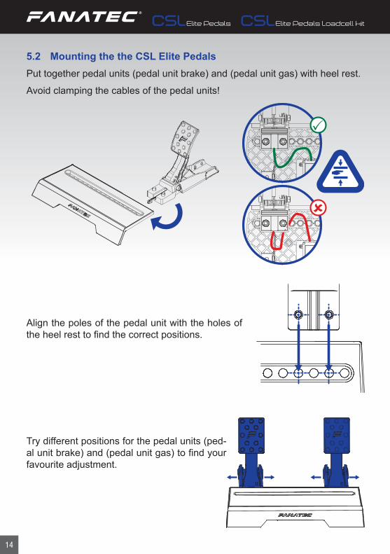
5.2 Mounting the the CSL Elite PedalsPut together pedal units (pedal unit brake) and (pedal unit gas) with heel rest.
Avoid clamping the cables of the pedal units!
Align the poles of the pedal unit with the holes of the heel rest to find the correct positions.
Try different positions for the pedal units (ped-al unit brake) and (pedal unit gas) to find your favourite adjustment.

15
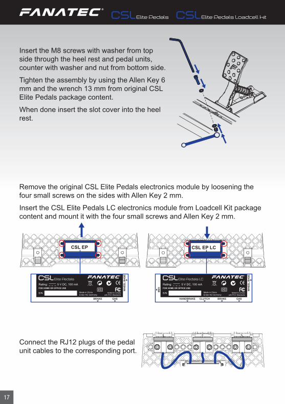
Insert the M8 screws with washer from top side through the heel rest and pedal unit (pedal unit brake)/(pedal unit gas), counter with washer and nut from bottom side.
Tighten the assembly by using the Allen Key and the wrench from package content.
When done insert the slot cover into the heel rest.
Connect the RJ12 plugs of the pedal unit cables to the corresponding port.
Store Allen Key and wrench safely for later use.

16
Align the poles of the pedal unit with the holes of the heel rest to find the correct positions.
Try different positions for the pedal units to find your favourite adjustment.
5.3 Mounting the CSL Elite Pedals LCPut together the pedal unit ‘loadcell brake’ (pedal unit loadcell brake) with heel rest of original CSL Elite Pedals (optional).Avoid clamping the cables of the pedal units!
17
Insert the M8 screws with washer from top side through the heel rest and pedal units, counter with washer and nut from bottom side.
Tighten the assembly by using the Allen Key 6 mm and the wrench 13 mm from original CSL Elite Pedals package content.
When done insert the slot cover into the heel rest.
Remove the original CSL Elite Pedals electronics module by loosening the four small screws on the sides with Allen Key 2 mm.
Insert the CSL Elite Pedals LC electronics module from Loadcell Kit package content and mount it with the four small screws and Allen Key 2 mm.
CSL EP CSL EP LC�
Connect the RJ12 plugs of the pedal unit cables to the corresponding port.
Made in ChinaEndor AG Germany
HANDBRAKE
USB W
HEE
L B
ASE
FOR HOME OR OFFICE USERating: 5 V DC, 100 mA
tested to complywith FCC Standards
CLUTCH BRAKE GAS
Made in ChinaEndor AG Germany
WH
EEL
BA
SE
FOR HOME OR OFFICE USERating: 5 V DC, 100 mA
tested to complywith FCC Standards
BRAKE GAS

18
Adjust the brake stiffness by arranging the different elastomer springs on the back side brake rod according to your setup and favour.The brake rod takes five pieces of elastomer springs plus the required soft yellow spring.Please refer to table of this Manual for correct setup!
Hardness Description Max. load Scenario / setup recommendation
Shore 65
Mediumhardness
18 kg Pedals on grippy floor or mounted to wheel stand
Shore 85
Hard 40 kg Pedals mounted to wheel stand or to rig / cockpit
Shore 95
Very hard 90 kg Pedals mounted to rig / cockpit
IMPORTANT: The elastomer springs must not be compressed more than 40% of their length so do not put more load on them than listed in table! If mixing brake springs with different hardness on the brake rod the maximum load is defined by the spring with lowest shore value!
Replace the brake limiter pad at the backside of the clutch pedal unit (former CSL Elite Pedals brake) by clutch limiter pad from CSL Elite Pedals Loadcell Kit package content.
19
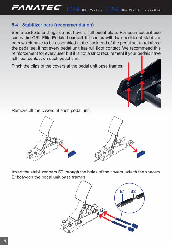
5.4 Stabilizer bars (recommendation)Some cockpits and rigs do not have a full pedal plate. For such special use cases the CSL Elite Pedals Loadcell Kit comes with two additional stabilizer bars which have to be assembled at the back end of the pedal set to reinforce the pedal set if not every pedal unit has full floor contact. We recommend this reinforcement for every user but it is not a strict requirement if your pedals have full floor contact on each pedal unit.
Pinch the clips of the covers at the pedal unit base frames:
Remove all the covers of each pedal unit:
Insert the stabilizer bars S2 through the holes of the covers, attach the spacers E1between the pedal unit base frames:
S2 E1

20
Add washers W1 and nuts N1 onto both ends of each stabilizer bar S2:
W1
N1
5.5 Hardmounting the CSL Elite Pedals and/or CSL Elite Pedals LCThe CSL Elite Pedals and CSL Elite Pedals LC offer hard-mount opportunity at several points of the pedal set as shown on the picture below:
• Heel rest: One hole at each corner for insertion of an M8 screw• Each single pedal unit: two holes at each pedal unit base frame
NOTE: Hard-mount screws are not included in the package contents.

21
To hard-mount the CSL Elite Pedals and/or CSL Elite Pedals LC to a rig by screws please find the printable drilling template in the download area of our website www.fanatec.com.
The drilling template shows the holes for all possible setus but of course it is only needed to drill the used holes depending on the pedal assembly setup.
NOTE: Always hardmount the pedals at the heel rest and at least with one screw at each pedal unit.
CSL EP
EN: When printing the Drilling Template at home, please make sure that the print size is 100% (�le size = print size).Therefore deactivate "automatic page scaling" in the print dialog for example.“
DE: Vergewissern Sie sich bei Druck der Bohrschablone zu Hause, dass die Druckgröße 100 % entspricht (Dateigröße = Druckgröße). Aus diesem Grund deaktivieren Sie bitte in den Druckeinstellungen die "automatische Seitenanpassung"
EN Top viewDE Ansicht von oben

22
5.6 Attaching / detaching the pedal plate rubber coversThe CSL Elite Pedals and the CSL Elite Pedals Loadcell Kit come with attached rubber covers on each pedal plate. These rubber covers can be removed to drive with a pure metal surface of the pedal plates with less grip.
The pedal plate rubber covers can be re-attached / detached at any time up to your favour:
IMPORTANT: Do not use any tools to attach or detach the pedal plate rubber covers to avoid damages, scratches and/or cuts on the product parts! The rubber covers are designed for attaching and detaching with-out tools.
5.7 Attaching anti-skid padsThe CSL Elite Pedals Loadcell Kit comes with three pieces anti-skid pads in the box content. These can be ap-plied to the pedal plates to provide a better grip for drivers using shoes.
To attach this first remove the pedal plate rubber cover as shown on the right hand side:

23
Then remove the film from the anti-skid pads backside:
Then attach the anti-skid pad onto the pedal plate:
NOTE: Make sure the pedal plate is clean and dry to allow a proper adhesion of the anti-skid pads!
The pedal plate rubber covers can be re-attached over the anti-skid pads at any time:

24
5.8. Connections CSL Elite PedalsTo connect your CSL Elite Pedals to PC or wheel base there are some connec-tor sockets at the bottom side of the CSL Elite Pedals mainboard:
5.8.1 Wheel BaseUse the RJ12 connection cable on this port and connect the other plug of the RJ12 cable to the wheel base port ‘Pedals’. This option is applicable for use of CSL Elite Pedals with PC or consoles.Or connect with the RJ12 cable to ClubSport USB Adapter for use on PC only.
IMPORTANT: Use only the RJ12 cable which is packaged with your CSL Elite Pedals to avoid damages on the CSL Elite Pedals electronics!
5.8.2 GasThis port is used for the connection to the gas / throttle pedal unit of the CSL Elite Pedals.
IMPORTANT: Do not try to use this port to connect any other device than the CSL Elite Pedals single pedal units!
5.8.3 BrakeThis port is used for the connection to the brake pedal unit of the CSL Elite Pedals.
IMPORTANT: Do not try to use this port to connect any other device than the CSL Elite Pedals single pedal units!
IMPORTANT: Use only the connection cables which are packaged with the CSL Elite Pedals and/or with the Wheel Bases! Wheel Bases and ClubSport USB Adapter are not included and sold separately!
Made in ChinaEndor AG Germany
WH
EEL
BA
SE
FOR HOME OR OFFICE USERating: 5 V DC, 100 mA
tested to complywith FCC Standards
BRAKE GAS

25
5.9 Connections CSL Elite Pedals LCTo connect your CSL Elite Pedals LC to PC or wheel base there are some con-nector sockets at the bottom side of the CSL Elite Pedals LC mainboard which comes with the CSL Elite Pedals Loadcell Kit:
Made in ChinaEndor AG Germany
HANDBRAKE
USB W
HEE
L B
ASE
FOR HOME OR OFFICE USERating: 5 V DC, 100 mA
tested to complywith FCC Standards
CLUTCH BRAKE GAS
5.9.1 Wheel BaseUse the RJ12 connection cable on this port and connect the other plug of the RJ12 cable to the wheel base port ‘Pedals’. This option is applicable for use of CSL Elite Pedals LC with PC or consoles.
IMPORTANT: Use only the RJ12 cable which is packaged with your CSL Elite Pedals to avoid damages on the CSL Elite Pedals electronics!
IMPORTANT: Do not connect to ClubSport USB Adapter to avoid any damages on the devices! Only use the USB socket of the CSL Elite Pedals LC mainboard for connection to PC USB port!
5.9.2 USBUse the USB connection cable on this port and connect the other plug of the USB cable to the USB port of your PC. This option is only applicable for use of CSL Elite Pedals LC with PC, not applicable for use of CSL Elite Pedals LC with consoles.
IMPORTANT: Use only the USB cable which is packaged with your CSL Elite Pedals Loadcell Kit to avoid damages on the CSL Elite Pedals LC electronics!
5.9.3 GasThis port is used for the connection to the gas / throttle pedal unit of the CSL Elite Pedals.

26
IMPORTANT: Do not try to use this port to connect any other device than the CSL Elite Pedals single pedal units, also not the loadcell brake unit!
5.9.4 BrakeThis port is used for the connection to the loadcell brake pedal unit of the CSL Elite Pedals Loadcell Kit.
IMPORTANT: Do not try to use this port to connect any other device than the loadcell pedal unit from CSL Elite Pedals Loadcell Kit!
5.9.5 ClutchThis port is used for the connection to the clutch pedal unit of the CSL Elite Pedals which is the original brake pedal unit from basic CSL Elite Pedals.
NOTE: This port does not need to be connected to the clutch pedal unit if you do not use a clutch at all. This allows you to use a similar flex-ible mechanical setup like with CSL Elite Pedals but with using the load-cell brake pedal unit from the CSL Elite Pedals Loadcell kit.
IMPORTANT: Do not try to use this port to connect any other device than the CSL Elite Pedals single pedal units, also not the loadcell brake unit!
5.9.6 HandbrakeThis port is used for connection of the ClubSport Handbrake. Cable needed to connect CSL Elite Pedals LC with ClubSport Handbrake is not included in the CSL Elite Pedals Loadcell Kit package but is included in the ClubSport Handbrake package.
IMPORTANT: Use only the connection cables which are packaged with the CSL Elite Pedals, CSL Elite Pedals Loadcell Kit and/or with the Wheel Bases! Wheel Bases and ClubSport Handbrake are not included and sold separately!
27
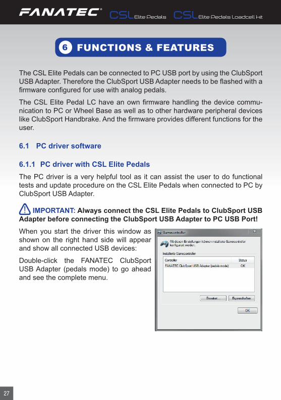
The CSL Elite Pedals can be connected to PC USB port by using the ClubSport USB Adapter. Therefore the ClubSport USB Adapter needs to be flashed with a firmware configured for use with analog pedals.
The CSL Elite Pedal LC have an own firmware handling the device commu- nication to PC or Wheel Base as well as to other hardware peripheral devices like ClubSport Handbrake. And the firmware provides different functions for the user.
6.1 PC driver software
6.1.1 PC driver with CSL Elite PedalsThe PC driver is a very helpful tool as it can assist the user to do functional tests and update procedure on the CSL Elite Pedals when connected to PC by ClubSport USB Adapter.
IMPORTANT: Always connect the CSL Elite Pedals to ClubSport USB Adapter before connecting the ClubSport USB Adapter to PC USB Port!When you start the driver this window as shown on the right hand side will appear and show all connected USB devices:
Double-click the FANATEC ClubSport USB Adapter (pedals mode) to go ahead and see the complete menu.
FUNCTIONS & FEATURES6

28
The next appearing menu ‘function test’ then is the function test window for pedals which includes signal indicators for gas, brake and clutch (clutch only for other analog pedals which come woth a clutch as well like the CSR pedals), see pictures below.
On the upper side of the PC driver you can switch from window ‘Function Test’ to window ‘Update’, see picture below:
There is also the button ‘Update USB Adapter Firmware’, see chapter ‘Firm-ware update procedure ClubSport USB Adapter’ of this manual for more de-tailed information about the firmware update process itself.

29
6.1.2 PC driver with CSL Elite Pedals LCThe PC driver is a very helpful tool as it can assist the user to do functional tests, adjustments and update procedure on the CSL Elite Pedals LC when connected to PC directly.
IMPORTANT: Do not connect the CSL Elite Pedals LC to PC USB through the ClubSport USB Adapter! Instead use the USB connection which the CSL Elite Pedals LC mainboard offers!When you start the driver this window as shown on the right hand side will appear and show all connected USB devices:
Double-click the FANATEC CSL Elite Pedals LC to go ahead and see the complete menu.
The next appearing menu ‘function test’ then is showing the CSL Elite Pedals LC, see picture below:

30
This window shows you a lot of different information and gives possibilities to test the currently used hardware and settings but also can be used for manual calibration:
On the upper left side there is a checkbox named ‘Enable auto calibration mode’ as shown on the right hand side (Note: This checkbox is shown on driver page ‘settings’ if CSL Elite Pedals LC are connected to wheel base):This checkbox is deactivated per default when auto calibration mode is active or after updating the CSL Elite Pedals LC firmware. Activate this checkbox manually to enable the manual calibration mode (indicated in driver window: The buttons right above and below each pedal indicator bar are displayed only when manual calibration mode is active after a moment). See chapter ‘Pedal manual calibration’ of this manual for more details about the calibration process itself.
On the lower left side you can see the indi-cator bars for each single pedal and for the ClubSport Handbrake, see picture on right hand side:
When pressing a pedal of the CSL Elite Ped-als the corresponding bar shows the signal level as a blue indicator, depending on the mechanical travel and on the manually cal-ibrated minimum and maximum positions. Same with the ClubSport Handbrake if con-nected to the CSL Elite Pedals LC.
Above every single indicator bar there are buttons ‘set max’, below every single indicator bar there are buttons ‘set min’. These buttons are only available when checkbox ‘Enable manual mode’ was activated by user before to enter manual calibration mode:
• When pressing a ‘set max’ button the current mechanical position of the corresponding pedal or the handbrake will be stored as the maximum position for this pedal or handbrake axis.
• When pressing a ‘set min’ button the current mechanical position of the corresponding pedal or the handbrake will be stored as the minimum position for this pedal or handbrake axis.
• See more detailed description in chapter ‘Pedal manual calibration’ of this manual.

31
Beside the indicator bar for the brake pedal there is another setting bar with an arrow, scaled into eleven stages (‘100’ on top end, ‘OFF’ on bottom end, indicated in the square above the brake axis indica-tor), see picture on right hand side:
This bar is only displayed and active when the Pedals are connect-ed to PC by USB directly. By moving the arrow from stage ‘OFF’ to stage ‘100’ the signal resistances of the brake pedal can be ad-justed: Increasing to 100 means the user needs to press the brake with maximum force to achieve 100% brake signal. Reducing to OFF means the user needs to press the brake only with a small force to achieve 100% brake signal.
NOTE: When the CSL Elite Pedals LC are connected to a wheel base this adjustment can be done in the wheel base tuning menu with param-eter BRF which has exactly the same functionality. Please read the user manual of your wheel base for more details.On the upper side of the PC driver you can switch from window ‘Function Test’ to window ‘Update’, see picture below:
This page gives you detailed informations about the currently installed PC driv-er version and the currently installed CSL Elite Pedals LC firmware version.
32
There is also the button ‘Update CSL Pedals LC Firmware’, see chapter ‘Firm-ware update procedure CSL Elite Pedals LC’ of this manual for more detailed information about the firmware update process itself.
6.2 Firmware and driver updateThe firmware and the PC driver can be updated to newer versions by Fanatec for software bug fixing or introduction of new features and compatibilities.
Before first use of the ClubSport USB Adapter with CSL Elite Pedals the Club-Sport USB Adapter has to be updated to the latest firmware version for pedals use which is included in the latest driver package available on our website www.fanatec.com/support.
Before first use CSL Elite Pedals LC electronics have to be updated to the lat-est firmware version which is included in the latest driver package available on our website www.fanatec.com/downloads.
You also have to use the latest PC driver version in order to use the CSL Elite Pedals and/or CSL Elite Pedals LC on a PC and perform the firmware updates.
Run the downloaded file(s) and follow the instructions shown on the screen.
See more detailed description later in this user manual chapter
IMPORTANT: The ClubSport USB Adapter firmware and the CSL Elite Pedals LC are secured by firmware and by driver so that usually it is not possible to install wrong firmwares on the devices! Do not try to force installation of any wrong firmware to the devices to avoid damages.
IMPORTANT: After firmware update the manually calibrated pedal po-sitions of the CSL Elite Pedals LC have to be manually calibrated again. Otherwise the CSL Elite Pedals LC uses the automatically calibrated posi-tions after pressing down each pedal to 100% of mechanical travel.This page gives you detailed informations about the currently installed PC driv-er version and the currently installed ClubSport USB Adapter firmware version.

33
6.1.2 Firmware update procedure ClubSport USB AdapterTo initiate the firmware update the ClubSport USB Adapter must be connected to the PC first. Then go to page ‘Update’ (see chapter ‘PC driver with CSL Elite Pedals’ of this manual) and press button ‘Update USB Adapter Firmware’ as shown on the right hand side:
Then the Firmware Updater starts, see picture below:
Right at start of the Firmware Updater the latest firmware file per driver default is selected and set. The user only has to select the ‘CSL Elite Pedals’ as the correct device.
Then press button ‘Start Update’ and the up-date process finishes:
Then disconnect the ClubSport USB Adapter and reconnect it again, the CSL Elite Pedals can be used now on PC USB port.
34
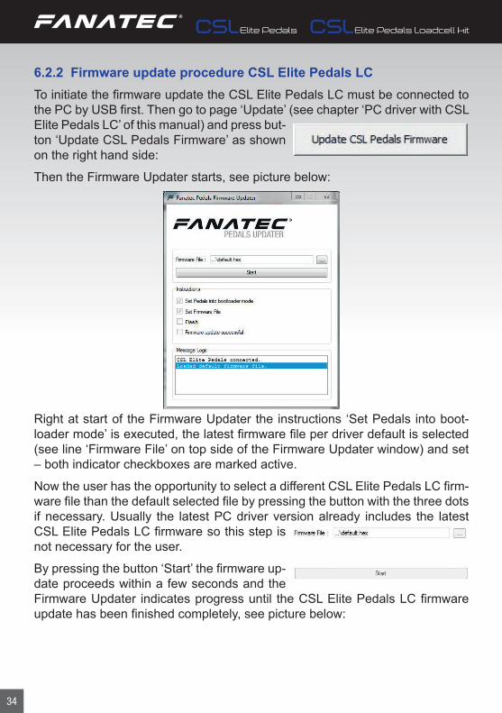
6.2.2 Firmware update procedure CSL Elite Pedals LCTo initiate the firmware update the CSL Elite Pedals LC must be connected to the PC by USB first. Then go to page ‘Update’ (see chapter ‘PC driver with CSL Elite Pedals LC’ of this manual) and press but-ton ‘Update CSL Pedals Firmware’ as shown on the right hand side:
Then the Firmware Updater starts, see picture below:
Right at start of the Firmware Updater the instructions ‘Set Pedals into boot-loader mode’ is executed, the latest firmware file per driver default is selected (see line ‘Firmware File’ on top side of the Firmware Updater window) and set – both indicator checkboxes are marked active.
Now the user has the opportunity to select a different CSL Elite Pedals LC firm-ware file than the default selected file by pressing the button with the three dots if necessary. Usually the latest PC driver version already includes the latest CSL Elite Pedals LC firmware so this step is not necessary for the user.
By pressing the button ‘Start’ the firmware up-date proceeds within a few seconds and the Firmware Updater indicates progress until the CSL Elite Pedals LC firmware update has been finished completely, see picture below:

35
When the firmware update has been finished the CSL Elite Pedals LC will re-boot automatically. As described on the Firmware Updater window please close the Firmware Updater application. Open the driver window again and check the CSL Elite Pedals LC functionality and calibration before next use.
IMPORTANT: The CSL Elite Pedals LC is secured by firmware and by driver so that usually it is not possible to install wrong firmware files on the CSL Elite Pedals LC! Do not try to force installation of any wrong firmware to the CSL Elite Pedals LC to avoid damages.
IMPORTANT: After firmware update the manually calibrated pedal po-sitions of the CSL Elite Pedals LC have to be manually calibrated again. Otherwise the CSL Elite Pedals uses the automatically calibrated posi-tions after pressing down each pedal to 100% of mechanical travel. See chapter ‘Pedal manual calibration’ of this manual for more details.
6.3. Start-Up procedureConnect the CSL Elite Pedals LC to the PC or wheel base, when the device is switched ON the CSL Elite Pedals are ON, too. The CSL Elite Pedals LC does not have an ON/OFF switch.

36
6.3 Pedal auto calibration modeFirst connect your ClubSport Handbrake to the ‘Handbrake’ port of your CSL Elite Pedals LC. If you do not use a handbrake skip this step.Then connect the CSL Elite Pedals LC to your PC or wheel base and switch ON the connected device.When the CSL Elite Pedals LC were powered without having done a manual calibration yet or after a firmware update the CSL Elite Pedals LC operates in auto calibration mode, the user can verify in PC driver, page ‘Function Test’, see picture on right hand side (Note: This checkbox is shown on driver page ‘settings’ if CSL Elite Pedals LC are connected to wheel base):To calibrate each pedal press every pedal lever from initial mechanical positiondown to 100% of pedal travel to maximum mechanical position and then backto initial mechanical position one time.Now the pressed pedal is calibrated automatically. The procedure for the hand-brake (if connected) is the same.
6.4 Pedal manual calibrationIf you want to make a more precise calibration of each pedal or even want to reduce the signal array within the mechanical travel you can do so by manual calibration.There are two different ways to do manual calibration:
• Manual calibration of minimum and maximum positions by PC dri-ver:
� Start PC driver application and monitor the single pedal signal indica-tor bars. Press the pedal to the wanted mechanical minimum position, then press the button ‘set min’ below the corresponding pedal indicator bar in PC driver. Now the new minimum position value is stored.
NOTE: Minimum position must be lower than maximum position, to be achieved by shorter physical travel of pedal lever during manual cali-bration.
� Start PC driver application and monitor the single pedal indicator bars. Press the pedal to the wanted mechanical maximum position, then press the button ‘set max’ above the corresponding pedal indicator bar in PC driver. Now the new maximum position value is stored.
NOTE: Maximum position must be higher than minimum position, to

37
be achieved by longer physical travel of pedal lever during manual cali-bration.
• Manual calibration of brake force by PC driver: � Beside the signal indicator bar for the brake pedal there is another set-ting bar with an arrow, scaled into eleven stages (‘100’ on top end, ‘Off’ on bottom end), see picture on right hand side. This bar is only active when checkbox ‘Enable manual calibration mode’ is active, and the pedals are connected to PC by USB directly. By moving the arrow from stage ‘OFF’ to stage ‘100’ the signal resistance of the brake pedal can be adjusted, the square above shows the current stage.
• Manual calibration of throttle and clutch by wheel base: � Press the clutch pedal and the throttle pedal to your wan-ted physical minimum position. Enter the Tuning Menu and press the button combination as follows on your attached steering wheel: Left Shifter Paddle + Right Shifter Paddle + Down on D-Pad Now the new minimum position values for both pedals are stored. After successfully calibrating the new minimum positions the display of the attached steering wheel shows ‘PNP’. Note: Minimum position must be lower than maximum position, to be achieved by shorter physical travel of pedal levers during manual calibration.
� Press the clutch pedal and the throttle pedal to your wanted physical maximum position. Enter the Tuning Menu and press the button com-bination as follows on your attached steering wheel: Left Shifter Paddle + Right Shifter Paddle + Up on D-Pad Now the new maximum position values for both pedals are stored. After successfully calibrating the new minimum positions the display of the attached steering wheel shows ‘PUP’. Note: Maximum position must be higher than minimum position, to be achieved by longer physi-cal travel of pedal levers during manual calibration.
• Brake force signal adjustment by wheel base: � Enter the Tuning Menu and navigate to parameter ‘BRF’ (brake force; is only shown if CSL Elite Pedals LC are connected to the wheel base) with default value 050. Change the value for ‘BRF’ according to your favourite setting within the range OFF to 100: - Value 100 means the user needs to press the brake with maximum force to achieve 100% brake signal - Value OFF means the user needs to press the brake only with a

38
small force to achieve 100% brake signal
ATTENTION: Manual calibration by driver is applicable when CSL Elite Pedals LC is connected to PC USB port or to wheel base. Manual calibration by wheel base is only applicable if CSL Elite Pedals LC is con-nected to the wheel base
NOTE: You can either check the brake signal level on the PC driver or you can see it on the RevLEDs of the CSL Elite Wheel Base and/or the attached Steering Wheel (depending on Steering Wheel type).
IMPORTANT: To switch back to auto calibration mode connect the CSL Elite Pedals LC to PC directly or to wheel base port ‘PEDAL’ and wheel base to PC. Then open the PC driver and activate the checkbox for ‘Enable manual calibration mode, see picture on right hand side:
For further information check the FAQ section on our websitewww.fanatec.com/Support

39
ELECTRICAL OPERATION
7.1 Hotkeys
This is a summary of all hotkeys related to the CSL Elite Pedals LC.
For the basic CSL Elite Pedals there are no hotkeys used.
NOTE: Note: Hotkeys are a functionality of the used Fanatec wheel base firmware. Wheel base firmware is subject to change.
7.1.1 Tuning menu
To enter the tuning menu use tuning menu button (usually the small black but- ton close to the LED display of the used Fanatec Steering Wheel; see correspond- ing quick guide of your Fanatec Steering Wheel). The picture just shows the tuning menu button on top of the ClubSport Uni- versal Hub as an example:
7.1.2 Pedals manual calibration (throttle and clutch)
First enter the Tuning menu by tuning menu button, then use these hotkeys to calibrate the minimum and maximum positions of the throttle and clutch pedals at the same time:
• Manual calibration of throttle and clutch pedals minimum position: Left Shifter Paddle + Right Shifter Paddle + Down on D-Pad
• Manual calibration of throttle and clutch pedals maximum position: Left Shifter Paddle + Right Shifter Paddle + Up on D-Pad
• Switch to auto calibration mode: Left Shifter Paddle + Right Shifter Paddle + Left on D-Pad
See chapter ‘Pedal manual calibration’ of this manual for more detailed infor-mation about the manual calibration process and auto calibration process.
7

40
MAINTENANCE9
Clean only with a dry or slightly damp cloth. Using cleaning solutions may dam- age your CSL Elite Pedals and/or CSL Elite Pedals LC.
CLEANING8
Please add some lithium grease to the parts where marked in the photos below when you can feel or even hear the parts grinding:

41
TROUBLESHOOTING10
The CSL Elite Pedals and/or the CSL Elite Pedals LC must not be modified dif-ferently than described in this manual. Endor® AG expressly prohibits analysis and utilization of the electronics, hardware, software and firmware contained in the controller. In case difficulties occur in connection with utilization of the CSL Elite Pedals and/or CSL Elite Pedals LC, please use the following guide for elimination of errors. On the website www.fanatec.com/support you will find further details and contact data.
If the CSL Elite Pedals and/or CSL Elite Pedals LC is not working properly:
Problem description Solution
After firmware update of the CSL Elite Pedals LC may manually calibrated positions are lost.
After doing a firmware update on the CSL Elite Pedals LC the manually calibrated pedal posi-tions have to be be manually calibrated again. See chapter ‘Pedals manual calibration’ and also Chapter Firmware update procedure’ of this manual for more details.
The PC driver or the wheel base does not recog-nize the CSL Elite Pedals / CSL Elite Pedals LC.
Make sure that you have updated your ClubSport USB Adapter firmware or CSL Elite Pedals LC firmware to the latest firmware version which can be downloaded from www.fanatec.com/ support.Make sure that you have updated your Fanatec wheel base to the latest firmware version which can be downloaded from www.fanatec.com/ downloads.Make sure that you have updated your PC driver to the latest version which can be downloaded from www.fanatec.com/ downloads.Make sure that the used RJ12 cable is plugged to the correct ports at CSL Elite Pedals bottom side and at ClubSport USB Adapter or wheel base.Make sure that the used cable (USB or RJ12) is plugged to the correct ports at CSL Elite Pedals LC bottom side and at PC or wheel base.
Pedal signal of CSL Elite Pedals and/or CSL Elite Pedals LC behaviour in game feels strange.
Connect the CSL Elite Pedals and/or CSL Elite Pedals LC to PC directly or through the wheel base. Start the PC driver and check the indicator bars of each pedal during pressing the corre-sponding pedal. On CSL Elite Pedals LC you may need to do manual calibration of minimum and / or maximum positions or reactivate the ‘Enable manual cali-bration mode’ to adjust the pedal signal behav-iour according to your favour.

42
Problem description Solution
After startup the CSL Elite Pedals and/or CSL Elite Pedals LC pedal signals are not correctly in-dicated, can be verified at PC driver.
When powering ON the CSL Elite Pedals LC in ‘Auto calibration mode’ every pedal lever must be pushed first to the maximum position and then back to the minimum position. When pressing the corresponding pedal lever then again the signal from the corresponding pedal should be fine. See chapter ‘Pedal auto calibration mode’ of this man-ual for more details.
My PC does not boot when CSL Elite Pedals LC are connected to USB before Windows is booted.
This phenomenon is related to some main board manufacturers’ BIOS. In this case the it is required to boot the PC first and then plug the CSL Elite Pedals LC to the USB port.

43
TRADEMARKS
SERIAL NUMBER
12
11
“Xbox®” and “Xbox OneTM” is a trademark of Microsoft Corporation. All rights reserved.
“FANATEC®” and “Endor®” are registered trademarks of Endor® AG/Germany. All rights reserved.
Before contacting the Fanatec Customer Support please note the serial num- ber of your CSL Elite Pedals: ………………………………………………...
Also please note the serial number of your CSL Elite Pedals Loadcell Kit: ………………………………………………...
You can find the serial numbers on a sticker on the bottom side of your CSL Elite Pedals and/or CSL Elite Pedals Loadcell Kit mainboard or on stickers on one of the packaging boxes.
The serial number for the CSL Elite Pedals starts with letters ‘ST’ and has ad-ditional 8 numbers, for example: ST64104013.
The serial number for the CSL Elite Pedals Loadcell Kit starts with letters ‘FS’ and has additional 8 numbers, for example: FS643902466.
Made in ChinaEndor AG Germany
HANDBRAKE
USB W
HEE
L B
ASE
FOR HOME OR OFFICE USERating: 5 V DC, 100 mA
tested to complywith FCC Standards
CLUTCH BRAKE GAS
Made in ChinaEndor AG Germany
WH
EEL
BA
SE
FOR HOME OR OFFICE USERating: 5 V DC, 100 mA
tested to complywith FCC Standards
BRAKE GAS

44
ECOLOGY ADVICE13
In the European Union: At the end of its working life, this product should not be disposed of with standard household waste, but rather dropped off at a collection point for the disposal of Waste Electrical and Electronic Equipment (WEEE) for recycling.
Depending on their characteristics, the materials may be recy-cled. Through recycling and other forms of processing Waste Electrical and Electronic Equipment, you can make a significant contribution towards helping to protect the environment.
Please contact your local authorities for information on the collection point nearest you.
For all other countries: Please adhere to local recycling laws for electrical and electronic equipment.
Retain this information. Colours and decorations may vary.
In the European Union: The packaging materials can be depollut-ed for recycling according to the legal regulations depending on the country responsible for the corresponding law.
For all other countries: Please adhere to local recycling laws for packaging materials.

45
FCC COMPLIANCE
CE COMPLIANCE
14
15
This device complies with part 15 of the FCC rules. The operation of this device is subject to the following two conditions:
• This device may not cause harmful interference, and must accept any interference received, including interference that may cause undesired operation.
• This device was not modified different than described explicitly in this user manual.
Note: This device was tested and approved to the limitations for class B of digital devices according to part 15 of the FCC rules. This limitations should en-sure an adequate protection against harming interferences in residental areas. However, a warranty for not-occuring of interferences is not assumed.
Do not modify the device different than described explicitly in this user manual. Nevertheless, if you do modifications different from the described in this manual you can be determined to stop the operation of the device.
This device complies with the European product regulations ac-cording to CE regulations.
The CE regulations contain basic requirements for safe usage of technical products.

46
WARRANTY16
Please check the FAQ database at www.fanatec.com/Support to see if your problem can be solved there. Normally, the warranty period is one year. How-ever, this may differ depending on the respective state.
1) Endor® AG grants for the hardware product – as extension of shorter na-tional warranty regulations, if applicable a one- year warranty for material and manufacturing defects. The warranty does not include defects that are due to commercial use of the product and/or normal wear and tear and/or damaging by third parties and/or improper utilization or treatment and/or utilization of the product contrary + to the operating and maintenance instructions and/or not in-tended installation and/or non-compliance with the local safety standards and/or the results of an intervention by a third party or a not authorized opening of the device including any measures for modification, adjustment and/or adap-tation measures (also in case of professional execution). Warranty applies as of the date of purchase when the final customer purchased the product, and is exclusively limited to the rights as of 2), as far as this does not limit any further legal warranty claims on the basis of various national laws. Warranty is subject to return of the defective product with carriage paid, within the warranty period, including the original receipt that must include date of purchase as well as the company stamp/company print of the first dealer.
2) The warranty covers – at the choice of Endor® AG – either gratis repair or re-placement of the device or components of the device. With defects that are not covered by the warranty and/or that are excluded from warranty (see above), possibilities for repair are to be requested with the local customer service or the local dealer. As far as permitted by law, any further liability - with the exception of intent and gross negligence – is excluded for any indirect or direct damages and consequential damages, regardless of whatsoever basis of claim.
This applies in particular to damages with other property, damages to persons, data losses as well as financial losses like loss of profit as well as transport damages in connection with returns to Endor® AG. As far as liability limitations are not legally allowed or effective in certain states or certain regions, the limi-tations are to be effective to such extent that exclusions of liability. This gaming device is designed to withstand approximately one hour of use per day during the course of the warranty period of one year.

Fanatec® is a registered trademark of Endor AGDesigned and developed by Endor AG in Germany10/2016