drum pedals
TRANSCRIPT


DRUM PEDAL PROJECT
• Nowadays, most drummers use a double pedal. Both beaters are attached to the kick-drum. The right beater is connected to the right pedal by a short linkage and the left beater is connected to the left pedal by a short linkage and a long shaft including 2 U-joints. Both beaters are connected to the frame by a return spring. The system pedal/shaft/linkage/beater/spring forms is equivalent to a torsional harmonic oscillator with a natural frequency:
• 𝒇 =𝟏
𝟐𝝅
𝒌
𝑰where K is the equivalent torsion coefficient and I the equivalent moment of inertia.
• Because of the added mass of the long shaft and linkage of the left pedal (higher moment of inertia) do not respond as well as the right pedal. It is slower and increasing the torsion coefficient makes it more difficult to operate.
DRUM PEDAL PROJECT
• There are basically 2 types of double pedal. The cheap ones, light but suffering from serious rigidity issues and questionable durability and the expensive ones, with all ball-bearing construction and (sadly) built like a tank as, it appears, that the more massive they are and the more appealing they are to the customer. (A drummer joke?...) The moment of inertia increases resulting in a slower pedal.
• The ideal pedal would have a pedal/shaft/linkages/beater’s shaft of zero mass with the total mass of the moving assembly concentrated into the beater head.
• In addition, the geometry of the linkage is very important in the way the pedal feels.
• The goal of the project was to design, fabricate and assemble a left pedal of minimum mass with adjustable geometric linkage.
SOME OLD SKETCHES
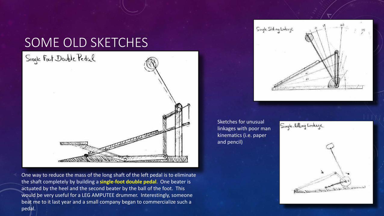
One way to reduce the mass of the long shaft of the left pedal is to eliminate the shaft completely by building a single-foot double pedal. One beater is actuated by the heel and the second beater by the ball of the foot. This would be very useful for a LEG AMPUTEE drummer. Interestingly, someone beat me to it last year and a small company began to commercialize such a pedal.
Sketches for unusual linkages with poor man kinematics (i.e. paper and pencil)
DRUM PEDAL
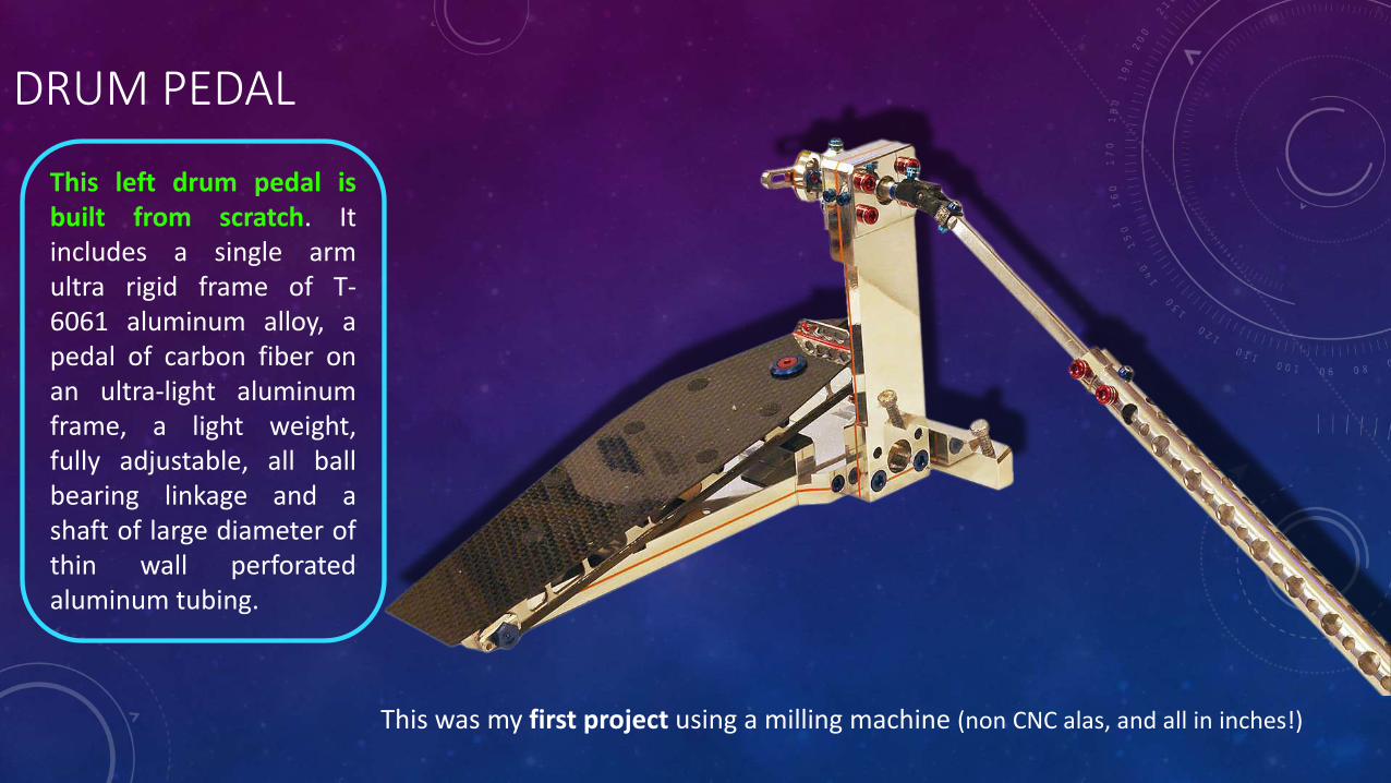
This left drum pedal isbuilt from scratch. Itincludes a single armultra rigid frame of T-6061 aluminum alloy, apedal of carbon fiber onan ultra-light aluminumframe, a light weight,fully adjustable, all ballbearing linkage and ashaft of large diameter ofthin wall perforatedaluminum tubing.
This was my first project using a milling machine (non CNC alas, and all in inches!)
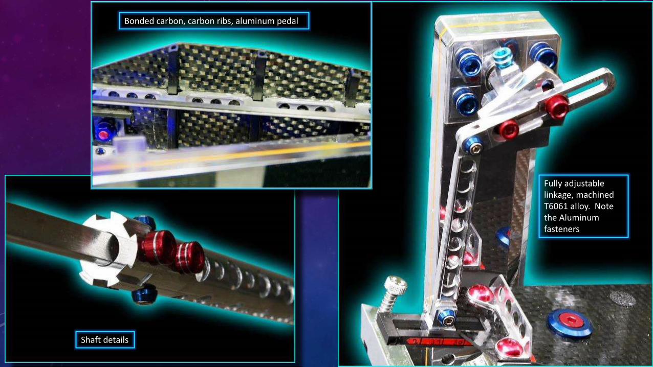
Bonded carbon, carbon ribs, aluminum pedal
Shaft details
Fully adjustable linkage, machined T6061 alloy. Note the Aluminum fasteners

RETURN
TO
MENU?

PEDAL PROJECT-2
• The pedal described earlier functioned very well and my son used it for several years until I purchased for him, last Christmas, a double pedal from Axis ($780, Ouch!), the only properly designed pedal on the market in my opinion.
• The shaft connecting the left pedal to the beater is a large part of the problem. So, why not eliminate the shaft completely? With this in mind, I decided to investigate the possibility of an electric pedal. The left pedal becomes a sensor capturing the motion of the foot and the signal is used to propel the beater.
PEDAL PROJECT-2GainOffset
Pot
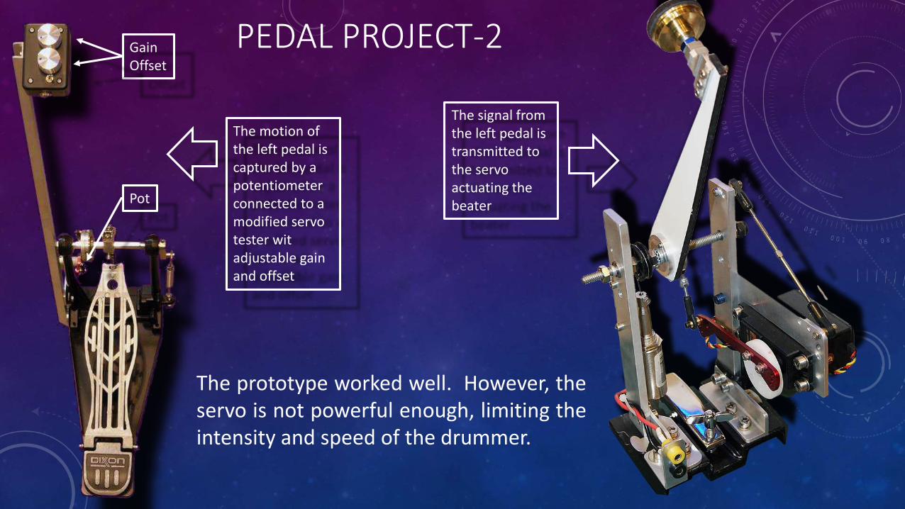
The signal from the left pedal is transmitted to the servo actuating the beater
The prototype worked well. However, theservo is not powerful enough, limiting theintensity and speed of the drummer.
The motion of the left pedal is captured by a potentiometer connected to a modified servo tester wit adjustable gain and offset

PEDAL PROJECT-2A
• The servo used in the proof of concept did not have the requiredtorque/speed capabilities required for “spirited” play, even though this servowas one of the most powerful analog servo available from the RC Hobbycommunity.
• Larger servomotors exist (CNC milling or routing application for example) butsuch expensive components were beyond the scope of this project. Weexperimented instead with a combination of servo and solenoids.
PEDAL PROJECT-2
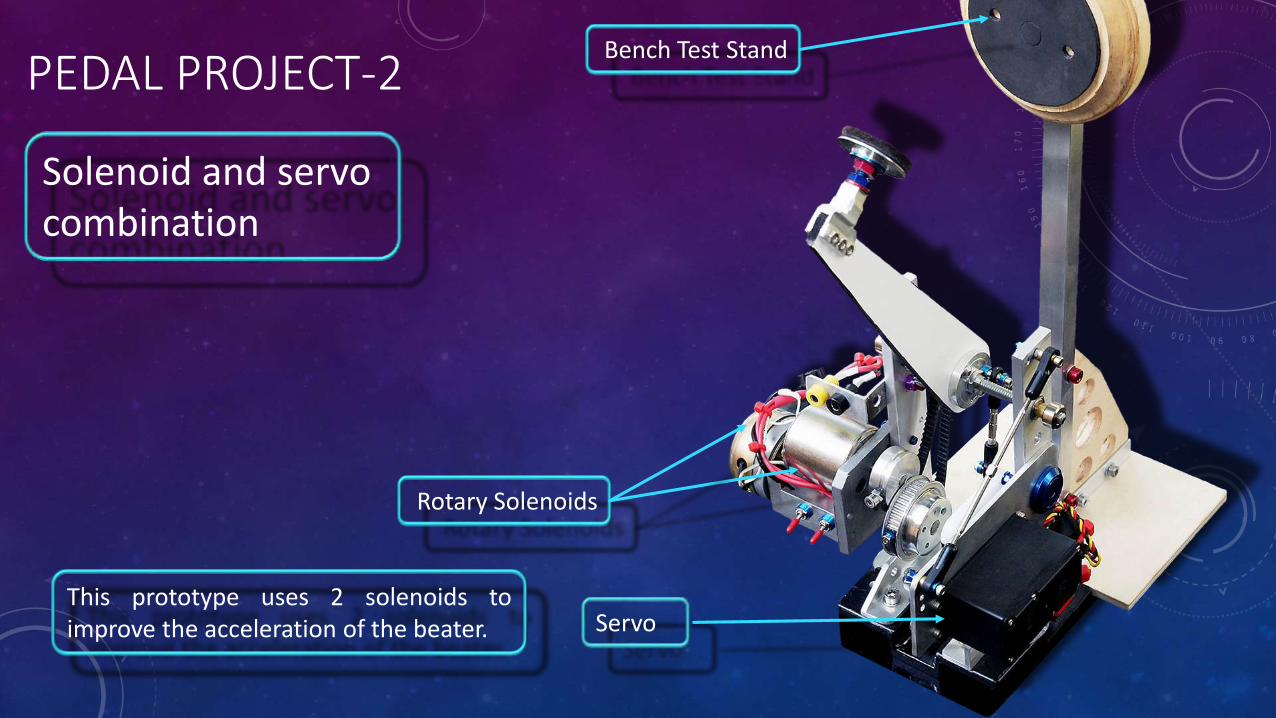
Rotary Solenoids
Servo
Solenoid and servo combination
This prototype uses 2 solenoids toimprove the acceleration of the beater.
Bench Test Stand
PEDAL PROJECT-2
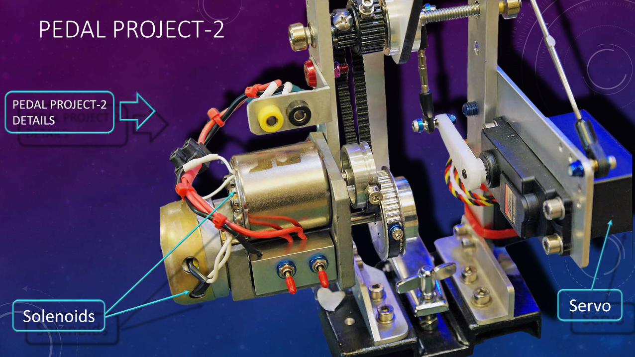
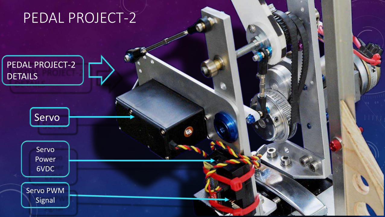
PEDAL PROJECT-2 DETAILS
SolenoidsServo
PEDAL PROJECT-2
PEDAL PROJECT-2 DETAILS
Servo Power6VDC
Servo
Servo PWM Signal

RETURN
TO
MENU?


PEDAL PROJECT - 3SEMI-ACTIVE PEDAL – CONCEPTUAL DESIGN
PEDAL PROJECT-3
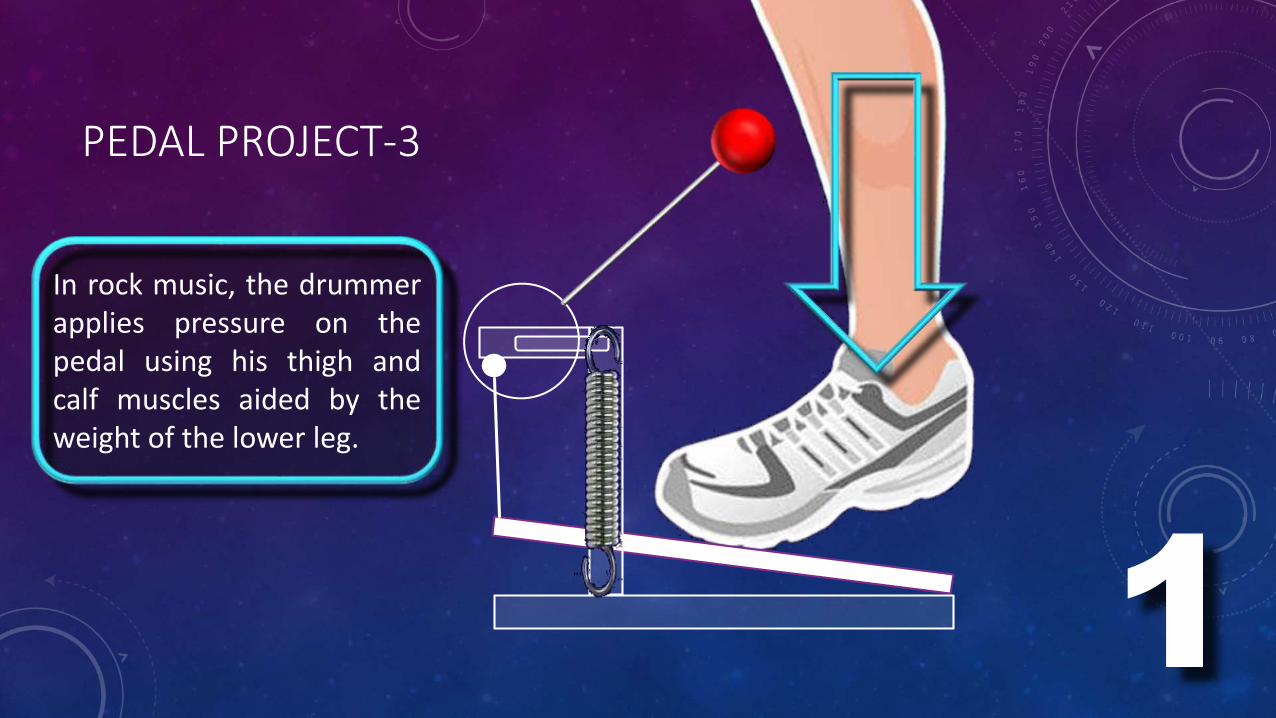
In rock music, the drummerapplies pressure on thepedal using his thigh andcalf muscles aided by theweight of the lower leg.
1
PEDAL PROJECT-3
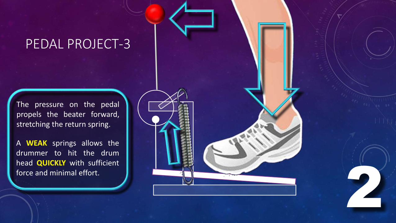
The pressure on the pedalpropels the beater forward,stretching the return spring.
2
A WEAK springs allows thedrummer to hit the drumhead QUICKLY with sufficientforce and minimal effort.
PEDAL PROJECT-3
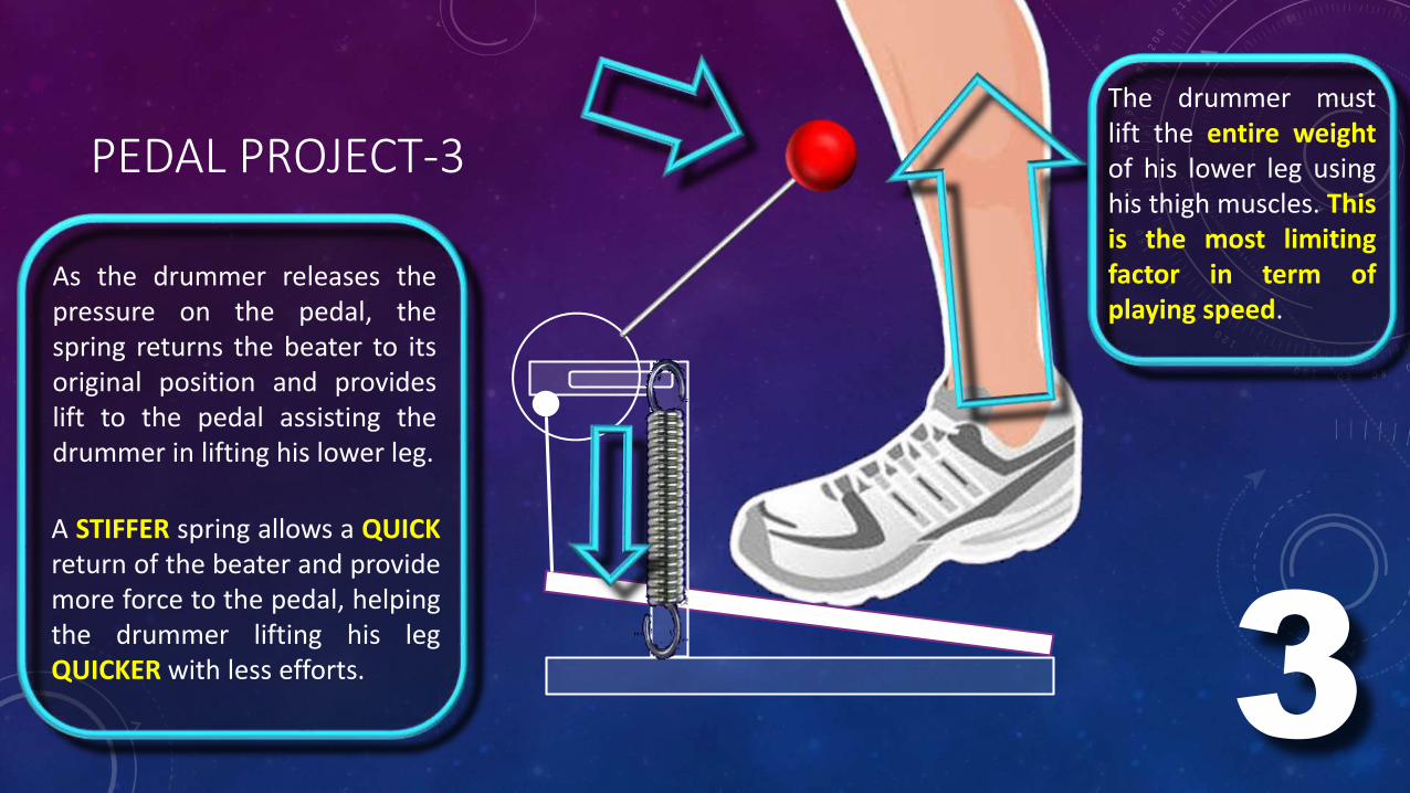
As the drummer releases thepressure on the pedal, thespring returns the beater to itsoriginal position and provideslift to the pedal assisting thedrummer in lifting his lower leg.
The drummer mustlift the entire weightof his lower leg usinghis thigh muscles. Thisis the most limitingfactor in term ofplaying speed.
3
A STIFFER spring allows a QUICKreturn of the beater and providemore force to the pedal, helpingthe drummer lifting his legQUICKER with less efforts.
PEDAL PROJECT-3
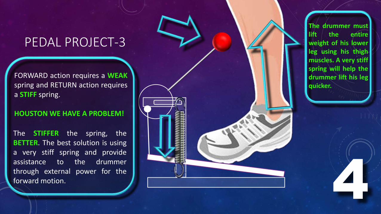
The STIFFER the spring, theBETTER. The best solution is usinga very stiff spring and provideassistance to the drummerthrough external power for theforward motion.
The drummer mustlift the entireweight of his lowerleg using his thighmuscles. A very stiffspring will help thedrummer lift his legquicker.
4
FORWARD action requires a WEAKspring and RETURN action requiresa STIFF spring.
HOUSTON WE HAVE A PROBLEM!
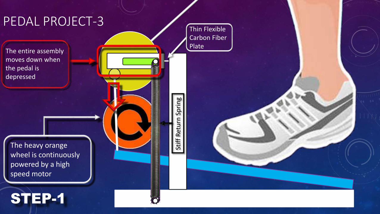
Thin Flexible Carbon Fiber Plate
PEDAL PROJECT-3
The entire assembly moves down when the pedal is depressed
The heavy orange wheel is continuously powered by a high speed motor
Stif
f R
etu
rn S
pri
ng
STEP-1
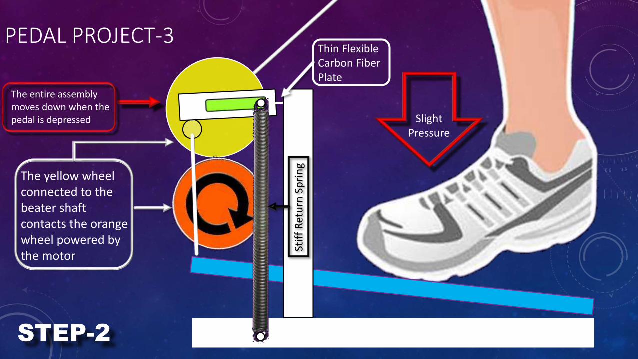
Thin Flexible Carbon Fiber Plate
PEDAL PROJECT-3
The entire assembly moves down when the pedal is depressed
The yellow wheel connected to the beater shaft contacts the orange wheel powered by the motor
Slight Pressure
Stif
f R
etu
rn S
pri
ng
STEP-2
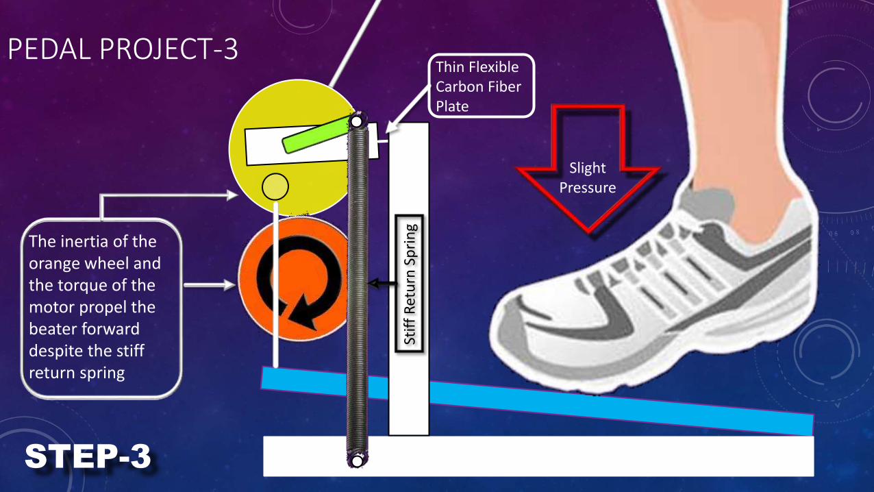
Thin Flexible Carbon Fiber Plate
PEDAL PROJECT-3
The inertia of the orange wheel and the torque of the motor propel the beater forward despite the stiff return spring
Stif
f R
etu
rn S
pri
ng
STEP-3
Slight Pressure
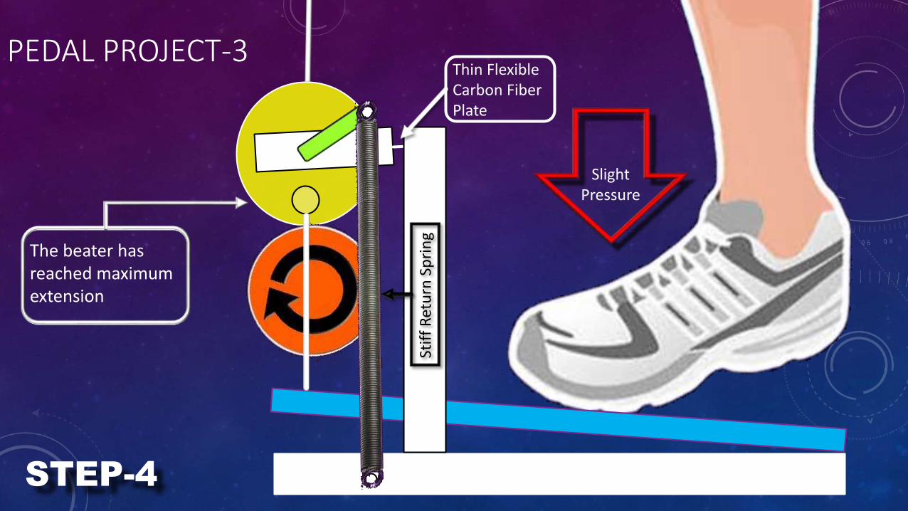
Thin Flexible Carbon Fiber Plate
PEDAL PROJECT-3
The beater has reached maximum extension
Slight Pressure
Stif
f R
etu
rn S
pri
ng
STEP-4
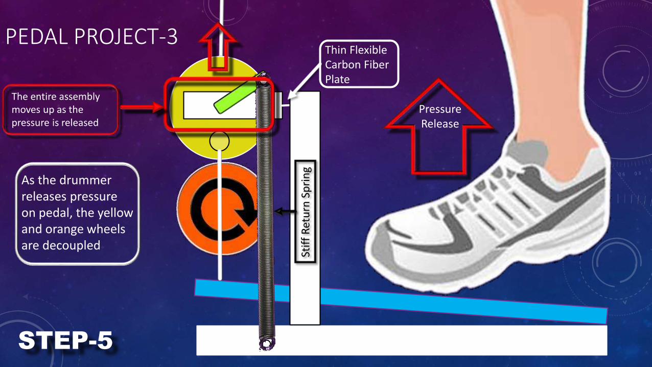
Thin Flexible Carbon Fiber Plate
PEDAL PROJECT-3
The entire assembly moves up as the pressure is released
As the drummer releases pressure on pedal, the yellow and orange wheels are decoupled
Pressure Release
Stif
f R
etu
rn S
pri
ng
STEP-5
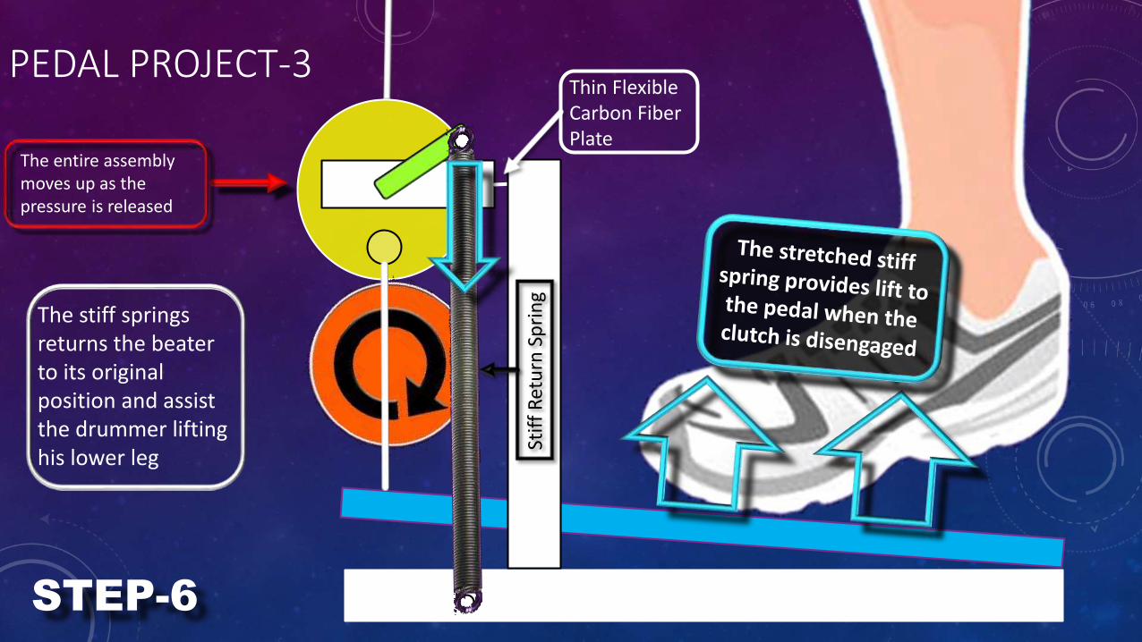
Thin Flexible Carbon Fiber Plate
PEDAL PROJECT-3
The stiff springs returns the beater to its original position and assist the drummer lifting his lower leg
Stif
f R
etu
rn S
pri
ng
STEP-6
The entire assembly moves up as the pressure is released
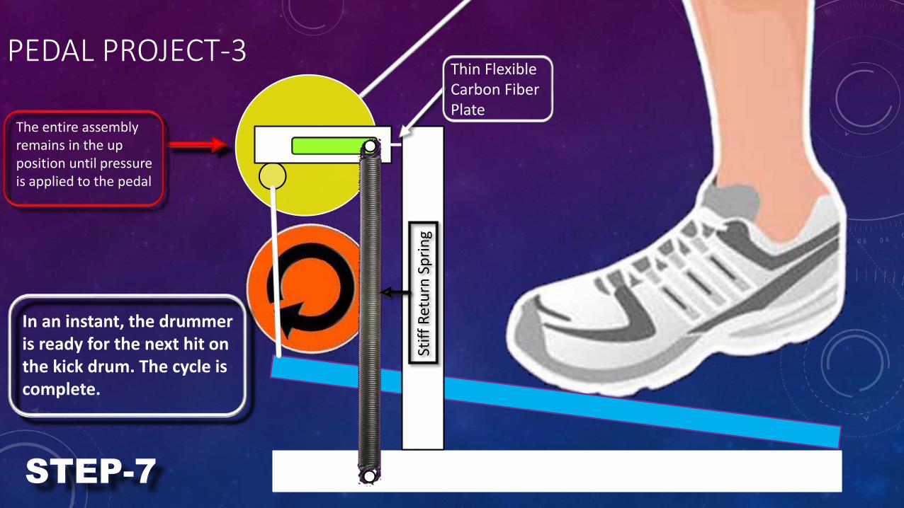
Thin Flexible Carbon Fiber Plate
PEDAL PROJECT-3
In an instant, the drummer is ready for the next hit on the kick drum. The cycle is complete.
Stif
f R
etu
rn S
pri
ng
STEP-7
The entire assembly remains in the up position until pressure is applied to the pedal
PEDAL PROJECT-3
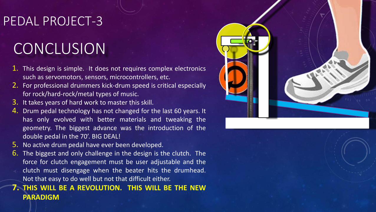
CONCLUSION1. This design is simple. It does not requires complex electronics
such as servomotors, sensors, microcontrollers, etc.2. For professional drummers kick-drum speed is critical especially
for rock/hard-rock/metal types of music.3. It takes years of hard work to master this skill.4. Drum pedal technology has not changed for the last 60 years. It
has only evolved with better materials and tweaking thegeometry. The biggest advance was the introduction of thedouble pedal in the 70’. BIG DEAL!
5. No active drum pedal have ever been developed.6. The biggest and only challenge in the design is the clutch. The
force for clutch engagement must be user adjustable and theclutch must disengage when the beater hits the drumhead.Not that easy to do well but not that difficult either.
7. THIS WILL BE A REVOLUTION. THIS WILL BE THE NEWPARADIGM

RETURN
TO
MENU?