conceptual plan - welcome to...
TRANSCRIPT

Conceptual Plan
i
Table of Contents
Sl. No. Contents Page Nos.
1.0 Introduction 1
1.1 Project Features and Location 1
1.2 Justification of the project 3
1.3 Proposal of Project Details (Area Statement) 3
1.4 Parking Requirements and Provisions 11
2.0 Water Requirement And Supply System 12
2.1 Source of water 14
2.2 Water Treatment system 14
2.3 Domestic water distribution system 16
2.4 Wastewater Treatment Technology 16
2.5 STP Process description 18
2.6 Storm water drainage and Rain Water Harvesting 20
3.0 Solid Waste collection / disposal plan 22
4.0 Power Requirement, Electrical, Building & fire safety
,DG sets details
24
4.1 General Description 24
4.2 Design Standards & Codes 24
4.3 Design Criteria 24
4.4 Electrical Load Estimates 25
4.5 Source of Power 26
4.6 Backup Power Supply 26
4.7 Landscape Plan 27
5.0 Fire fighting system 28
5.1 Firefighting system description 29
5.2 Sprinkling system 31
5.3 Smoke detection and automatic fire alarm system 32
5.4 Fire Extinguishers 33
5.5 Fire smoke exhaust system 37
6.0 Project Monitoring 38
6.1 Monitoring Strategy 38
6.2 Ambient Air Monitoring 38
6.3 Noise Monitoring 39
6.4 Water Quality Monitoring 39
6.5 Monitoring of STP 39
6.6 Budget for EMP 39
6.7 Environment Management Plan 40
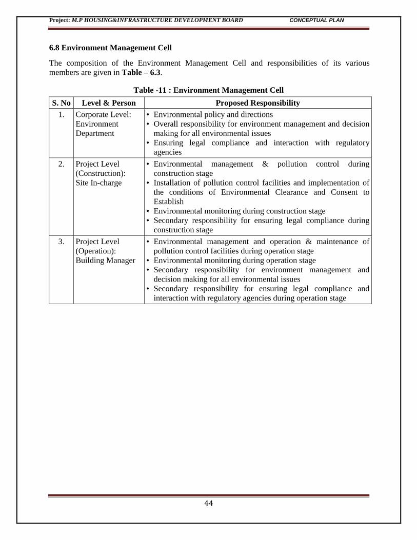
6.8 Environment Management Cell 44
ii
List of Tables
List of Figures
Sl. No. Figures Page Nos.
1 Photographs of proposed project site 5
2 Google image showing project site 6
3 Topographical Map showing 10 km radius 7
4 Project Layout Plan 8
5 Schematic plan of Water Supply system 16
6 STP schematic plan 18
List of Annexures:
Sl. No. Annexures Page Nos.
1 NOC for Water Supply from Indore Municipal Corporation 14
2 NOC for Sewerage disposal from Indore Municipal
Corporation
15
3 NOC for Solid waste disposal from Indore Municipal
Corporation
23
Sl. No. Tables Page Nos.
1 Permissible Activities as proposed hereunder 3
2 Detailed Area Statement 9
3 Calculation of population (Occupancy load) 12
4 Water Balance statement (Daily water requirement,
wastewater generation calculation etc)
13
5 Solid Waste Generation during operation phase 22
6 Design criteria for Energy Efficiency 24
7 Electrical Load Estimates 25
8 EMP Budget 39
9 Proposed Environmental Mitigation Measures 41
10 Environmental Monitoring Plan – Operation Phase 43
11 Environment Management Cell 44
Project: M.P HOUSING&INFRASTRUCTURE DEVELOPMENT BOARD CONCEPTUAL PLAN
1
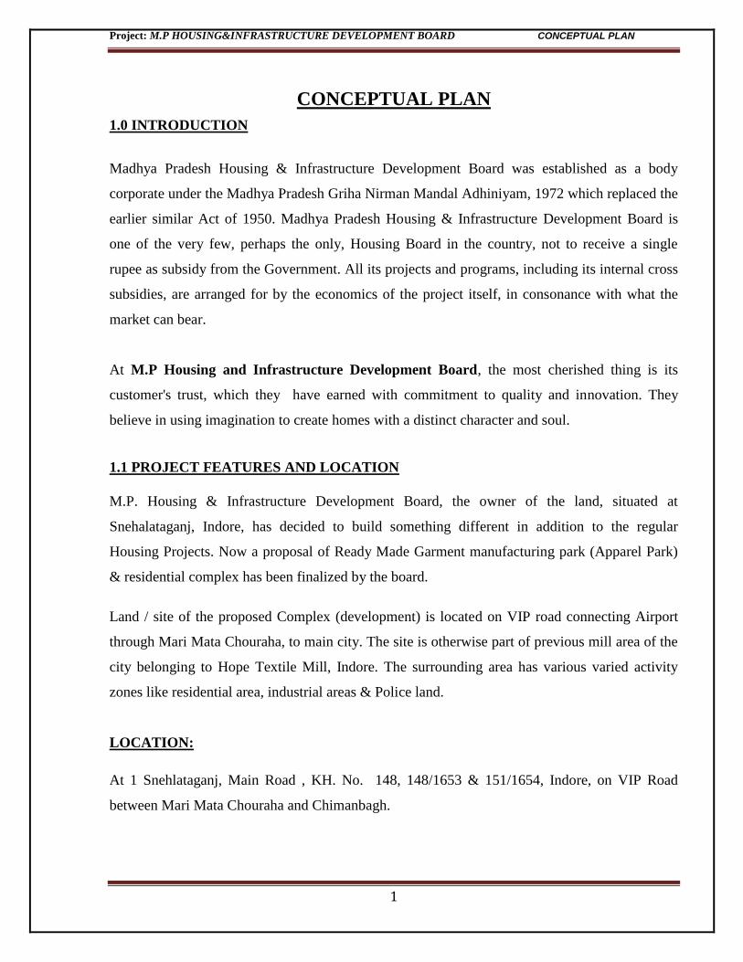
CONCEPTUAL PLAN
1.0 INTRODUCTION
Madhya Pradesh Housing & Infrastructure Development Board was established as a body
corporate under the Madhya Pradesh Griha Nirman Mandal Adhiniyam, 1972 which replaced the
earlier similar Act of 1950. Madhya Pradesh Housing & Infrastructure Development Board is
one of the very few, perhaps the only, Housing Board in the country, not to receive a single
rupee as subsidy from the Government. All its projects and programs, including its internal cross
subsidies, are arranged for by the economics of the project itself, in consonance with what the
market can bear.
At M.P Housing and Infrastructure Development Board, the most cherished thing is its
customer's trust, which they have earned with commitment to quality and innovation. They
believe in using imagination to create homes with a distinct character and soul.
1.1 PROJECT FEATURES AND LOCATION
M.P. Housing & Infrastructure Development Board, the owner of the land, situated at
Snehalataganj, Indore, has decided to build something different in addition to the regular
Housing Projects. Now a proposal of Ready Made Garment manufacturing park (Apparel Park)
& residential complex has been finalized by the board.
Land / site of the proposed Complex (development) is located on VIP road connecting Airport
through Mari Mata Chouraha, to main city. The site is otherwise part of previous mill area of the
city belonging to Hope Textile Mill, Indore. The surrounding area has various varied activity
zones like residential area, industrial areas & Police land.
LOCATION:
At 1 Snehlataganj, Main Road , KH. No. 148, 148/1653 & 151/1654, Indore, on VIP Road
between Mari Mata Chouraha and Chimanbagh.
Project: M.P HOUSING&INFRASTRUCTURE DEVELOPMENT BOARD CONCEPTUAL PLAN
2
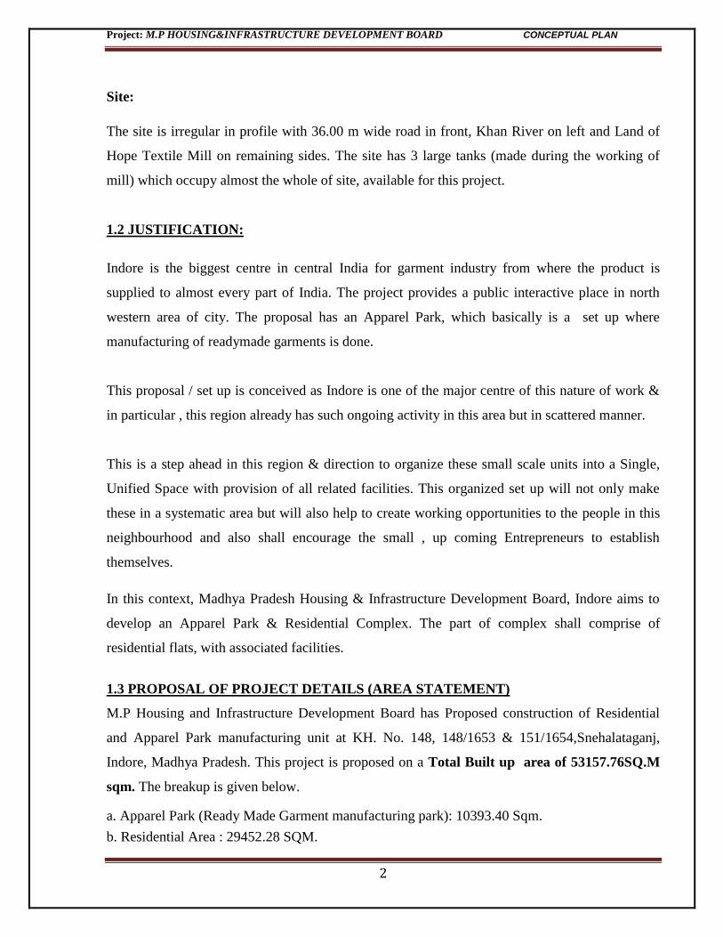
Site:
The site is irregular in profile with 36.00 m wide road in front, Khan River on left and Land of
Hope Textile Mill on remaining sides. The site has 3 large tanks (made during the working of
mill) which occupy almost the whole of site, available for this project.
1.2 JUSTIFICATION:
Indore is the biggest centre in central India for garment industry from where the product is
supplied to almost every part of India. The project provides a public interactive place in north
western area of city. The proposal has an Apparel Park, which basically is a set up where
manufacturing of readymade garments is done.
This proposal / set up is conceived as Indore is one of the major centre of this nature of work &
in particular , this region already has such ongoing activity in this area but in scattered manner.
This is a step ahead in this region & direction to organize these small scale units into a Single,
Unified Space with provision of all related facilities. This organized set up will not only make
these in a systematic area but will also help to create working opportunities to the people in this
neighbourhood and also shall encourage the small , up coming Entrepreneurs to establish
themselves.
In this context, Madhya Pradesh Housing & Infrastructure Development Board, Indore aims to
develop an Apparel Park & Residential Complex. The part of complex shall comprise of
residential flats, with associated facilities.
1.3 PROPOSAL OF PROJECT DETAILS (AREA STATEMENT)
M.P Housing and Infrastructure Development Board has Proposed construction of Residential
and Apparel Park manufacturing unit at KH. No. 148, 148/1653 & 151/1654,Snehalataganj,
Indore, Madhya Pradesh. This project is proposed on a Total Built up area of 53157.76SQ.M
sqm. The breakup is given below.
a. Apparel Park (Ready Made Garment manufacturing park): 10393.40 Sqm.
b. Residential Area : 29452.28 SQM.

Project: M.P HOUSING&INFRASTRUCTURE DEVELOPMENT BOARD CONCEPTUAL PLAN
3
c. Basement area (Lower basement of Residential Block + Upper basement of Commercial
Block) = 13312.08sq.m.
Table 1: Permissible Activities as proposed hereunder, are as per the Provisions of Master
Plan
Commercial Residential
Apparel Park in Gr. Floor to 7th Floor Block A : Stilt + 14 Floors + Service
Floor – 3 BHK (98 Flats )
Block B: Stilt + 14 Floors + Service
Floor – 2 BHK (94 Flats )
The project is proposed with 45.00m high, 3 towers & 24.00 m high one tower with varied
building heights as mentioned above, covering 30% only on ground. Remaining area is left open
for circulation and parking. The proposal has green areas, not only on the ground level, but even
on the upper floors, as terrace garden.
CIRCULATION
The access to the site is predominantly from front 36.00 m wide road (VIP road connecting
Airport to central Indore City). 7.50 m wide road loop is proposed within site which gives
accesses to all the blocks and is connected to the entry & exit of basement parking. Parking
entries to Apparel Park and Residential blocks are separate.
The Ready Made Garment manufacturing park (Apparel Park) has separate entry / exit in front
with approach to service yard on back side for the block to accesses the Cargo Lift. This block
has part, reserved parking in upper basement in addition to off street parking in front.
The residential blocks are approached by separate peripheral road all round both for approach to
each block & also for the Fire Engine movement. These blocks have 2 basements for the parking
as well as open parking area. Separate entry / exit to each tower which in turn has adequate lifts
& staircase for vertical circulation, not only from stilt but from upper & lower basement.
The campus has clear vehicular circulation on ground, for Public as well as for Fire Engines –
an important factor for any high rise building.Proper care is taken to provide safe & separate
pedestrian pathway net work with the campus & to the main approach road of the Complex.
Project: M.P HOUSING&INFRASTRUCTURE DEVELOPMENT BOARD CONCEPTUAL PLAN
4
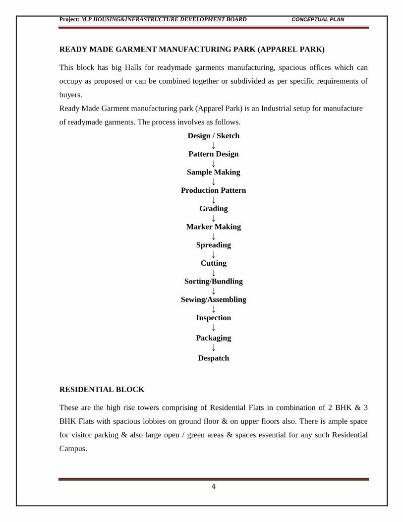
READY MADE GARMENT MANUFACTURING PARK (APPAREL PARK)
This block has big Halls for readymade garments manufacturing, spacious offices which can
occupy as proposed or can be combined together or subdivided as per specific requirements of
buyers.
Ready Made Garment manufacturing park (Apparel Park) is an Industrial setup for manufacture
of readymade garments. The process involves as follows.
Design / Sketch
↓
Pattern Design
↓
Sample Making
↓
Production Pattern
↓
Grading
↓
Marker Making
↓
Spreading
↓
Cutting
↓
Sorting/Bundling
↓
Sewing/Assembling
↓
Inspection
↓
Packaging
↓
Despatch
RESIDENTIAL BLOCK
These are the high rise towers comprising of Residential Flats in combination of 2 BHK & 3
BHK Flats with spacious lobbies on ground floor & on upper floors also. There is ample space
for visitor parking & also large open / green areas & spaces essential for any such Residential
Campus.
Project: M.P HOUSING&INFRASTRUCTURE DEVELOPMENT BOARD CONCEPTUAL PLAN
5
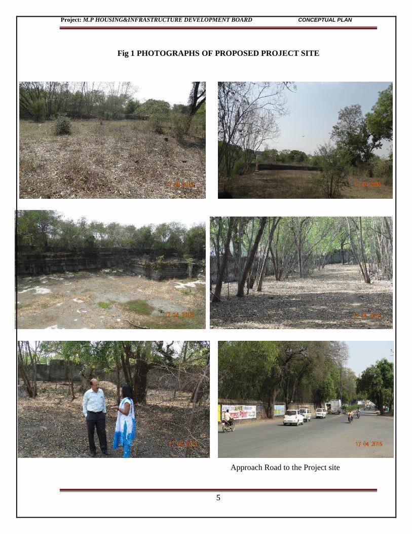
Fig 1 PHOTOGRAPHS OF PROPOSED PROJECT SITE
Approach Road to the Project site
Project: M.P HOUSING&INFRASTRUCTURE DEVELOPMENT BOARD CONCEPTUAL PLAN
6
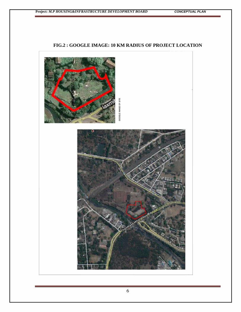
FIG.2 : GOOGLE IMAGE: 10 KM RADIUS OF PROJECT LOCATION
Project: M.P HOUSING&INFRASTRUCTURE DEVELOPMENT BOARD CONCEPTUAL PLAN
7
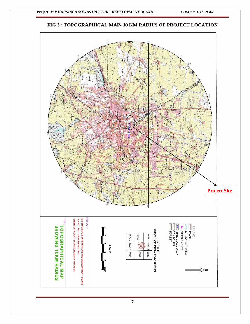
FIG 3 : TOPOGRAPHICAL MAP- 10 KM RADIUS OF PROJECT LOCATION
Project Site
Project: M.P HOUSING&INFRASTRUCTURE DEVELOPMENT BOARD CONCEPTUAL PLAN
8
FIG 4 : PROJECT LAYOUT PLAN
Project: M.P HOUSING&INFRASTRUCTURE DEVELOPMENT BOARD CONCEPTUAL PLAN
9
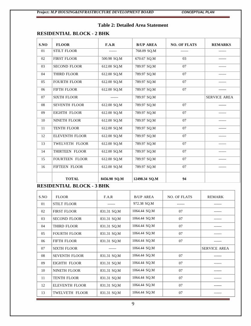
Table 2: Detailed Area Statement
RESIDENTIAL BLOCK - 2 BHK
RESIDENTIAL BLOCK - 3 BHK
S.NO
FLOOR
F.A.R
B/UP AREA
NO. OF FLATS
REMARK
01 STILT FLOOR ------ 972.38 SQ.M ------ ------
02 FIRST FLOOR 831.31 SQ.M 1064.44 SQ.M 07 ------
03 SECOND FLOOR 831.31 SQ.M 1064.44 SQ.M 07 ------
04 THIRD FLOOR 831.31 SQ.M 1064.44 SQ.M 07 ------
05 FOURTH FLOOR 831.31 SQ.M 1064.44 SQ.M 07 ------
06 FIFTH FLOOR 831.31 SQ.M 1064.44 SQ.M 07 ------
07 SIXTH FLOOR ------ 1064.44 SQ.M SERVICE AREA
08 SEVENTH FLOOR 831.31 SQ.M 1064.44 SQ.M 07 ------
09 EIGHTH FLOOR 831.31 SQ.M 1064.44 SQ.M 07 ------
10 NINETH FLOOR 831.31 SQ.M 1064.44 SQ.M 07 ------
11 TENTH FLOOR 831.31 SQ.M 1064.44 SQ.M 07 ------
12 ELEVENTH FLOOR 831.31 SQ.M 1064.44 SQ.M 07 ------
13 TWELVETH FLOOR 831.31 SQ.M 1064.44 SQ.M 07 ------
S.NO
FLOOR
F.A.R
B/UP AREA
NO. OF FLATS
REMARKS
01 STILT FLOOR ------ 768.09 SQ.M ------ ------
02 FIRST FLOOR 500.98 SQ.M 670.67 SQ.M 03 ------
03 SECOND FLOOR 612.00 SQ.M 789.97 SQ.M 07 ------
04 THIRD FLOOR 612.00 SQ.M 789.97 SQ.M 07 ------
05 FOURTH FLOOR 612.00 SQ.M 789.97 SQ.M 07 ------
06 FIFTH FLOOR 612.00 SQ.M 789.97 SQ.M 07 ------
07 SIXTH FLOOR ------ 789.97 SQ.M SERVICE AREA
08 SEVENTH FLOOR 612.00 SQ.M 789.97 SQ.M 07 ------
09 EIGHTH FLOOR 612.00 SQ.M 789.97 SQ.M 07 ------
10 NINETH FLOOR 612.00 SQ.M 789.97 SQ.M 07 ------
11 TENTH FLOOR 612.00 SQ.M 789.97 SQ.M 07 ------
12 ELEVENTH FLOOR 612.00 SQ.M 789.97 SQ.M 07 ------
13 TWELVETH FLOOR 612.00 SQ.M 789.97 SQ.M 07 ------
14 THIRTEEN FLOOR 612.00 SQ.M 789.97 SQ.M 07 ------
15 FOURTEEN FLOOR 612.00 SQ.M 789.97 SQ.M 07 ------
16 FIFTEEN FLOOR 612.00 SQ.M 789.97 SQ.M 07 ------
TOTAL
8456.98 SQ.M
12498.34 SQ.M
94
Project: M.P HOUSING&INFRASTRUCTURE DEVELOPMENT BOARD CONCEPTUAL PLAN
10
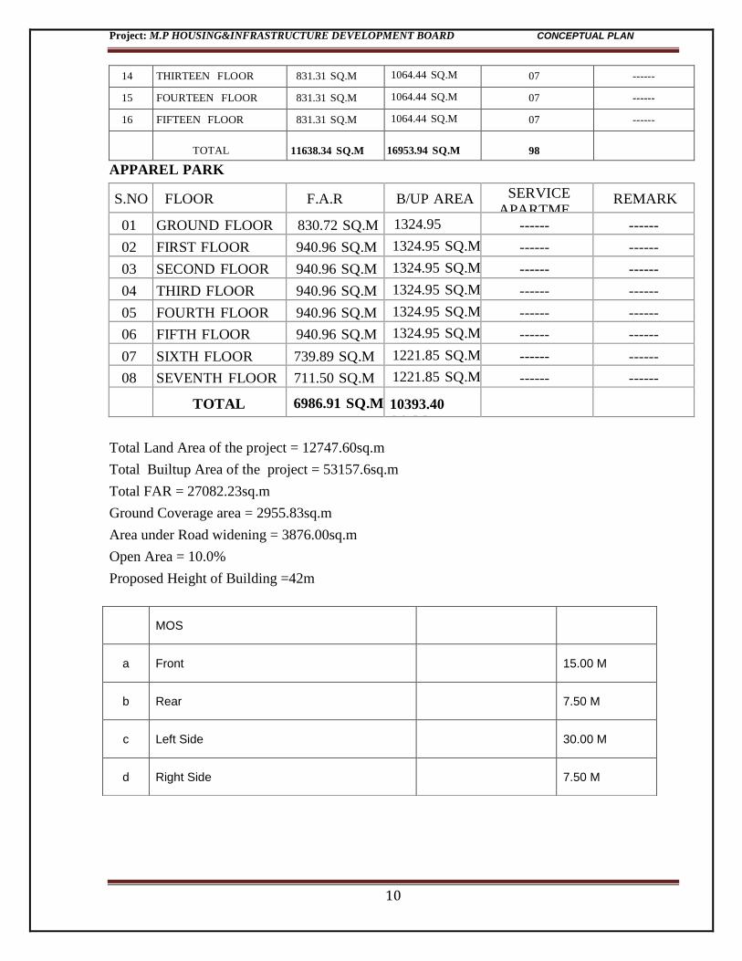
14 THIRTEEN FLOOR 831.31 SQ.M 1064.44 SQ.M 07 ------
15 FOURTEEN FLOOR 831.31 SQ.M 1064.44 SQ.M 07 ------
16 FIFTEEN FLOOR 831.31 SQ.M 1064.44 SQ.M 07 ------
TOTAL
11638.34 SQ.M
16953.94 SQ.M
98
APPAREL PARK
S.NO
FLOOR
F.A.R
B/UP AREA SERVICE
APARTME
NT
REMARK
01 GROUND FLOOR 830.72 SQ.M 1324.95
SQ.M ------ ------
02 FIRST FLOOR 940.96 SQ.M 1324.95 SQ.M ------ ------
03 SECOND FLOOR 940.96 SQ.M 1324.95 SQ.M ------ ------
04 THIRD FLOOR 940.96 SQ.M 1324.95 SQ.M ------ ------
05 FOURTH FLOOR 940.96 SQ.M 1324.95 SQ.M ------ ------
06 FIFTH FLOOR 940.96 SQ.M 1324.95 SQ.M ------ ------
07 SIXTH FLOOR 739.89 SQ.M 1221.85 SQ.M ------ ------
08 SEVENTH FLOOR 711.50 SQ.M 1221.85 SQ.M ------ ------
TOTAL
6986.91 SQ.M
10393.40
SQ.M
Total Land Area of the project = 12747.60sq.m
Total Builtup Area of the project = 53157.6sq.m
Total FAR = 27082.23sq.m
Ground Coverage area = 2955.83sq.m
Area under Road widening = 3876.00sq.m
Open Area = 10.0%
Proposed Height of Building =42m
MOS
a Front 15.00 M
b Rear 7.50 M
c Left Side 30.00 M
d Right Side 7.50 M
Project: M.P HOUSING&INFRASTRUCTURE DEVELOPMENT BOARD CONCEPTUAL PLAN
11
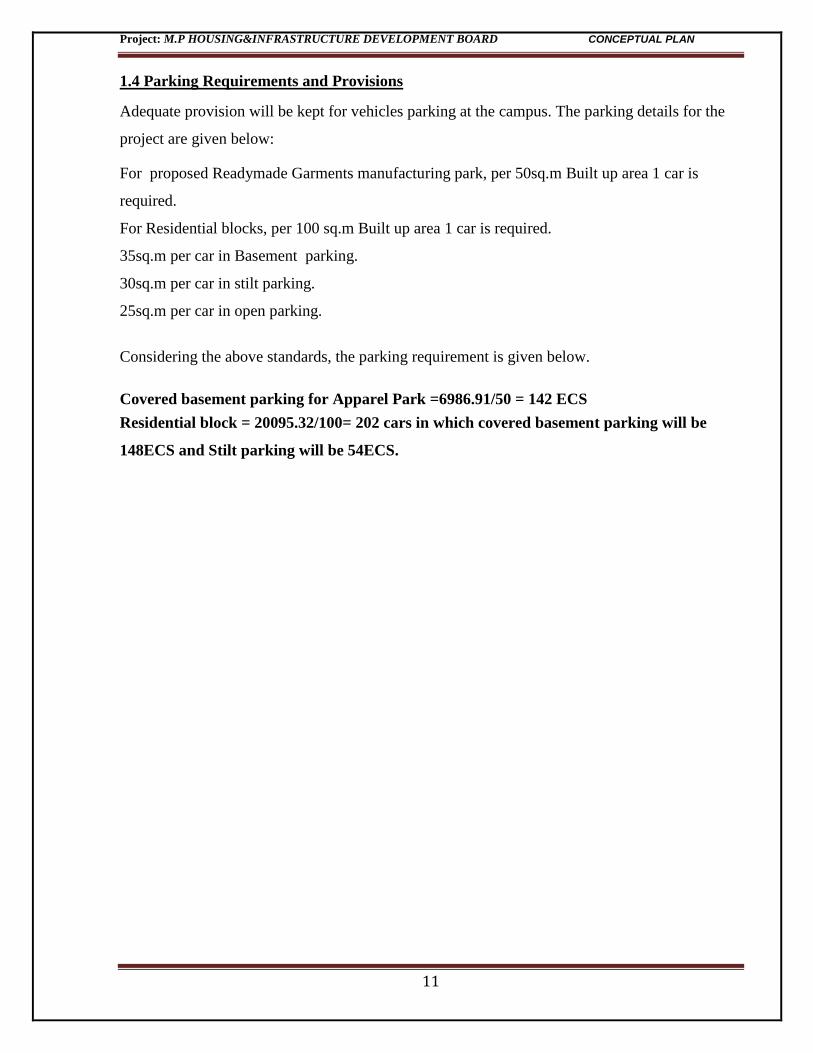
1.4 Parking Requirements and Provisions
Adequate provision will be kept for vehicles parking at the campus. The parking details for the
project are given below:
For proposed Readymade Garments manufacturing park, per 50sq.m Built up area 1 car is
required.
For Residential blocks, per 100 sq.m Built up area 1 car is required.
35sq.m per car in Basement parking.
30sq.m per car in stilt parking.
25sq.m per car in open parking.
Considering the above standards, the parking requirement is given below.
Covered basement parking for Apparel Park =6986.91/50 = 142 ECS
Residential block = 20095.32/100= 202 cars in which covered basement parking will be
148ECS and Stilt parking will be 54ECS.
Project: M.P HOUSING&INFRASTRUCTURE DEVELOPMENT BOARD CONCEPTUAL PLAN
12
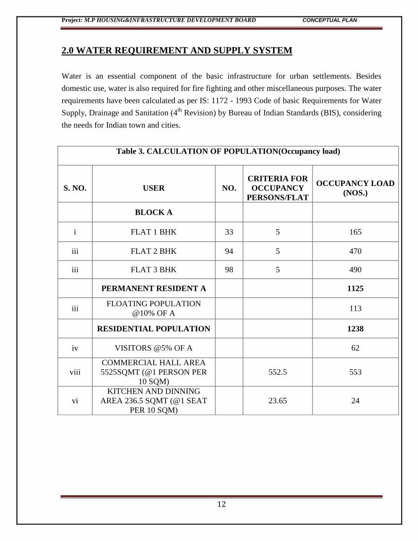
2.0 WATER REQUIREMENT AND SUPPLY SYSTEM
Water is an essential component of the basic infrastructure for urban settlements. Besides
domestic use, water is also required for fire fighting and other miscellaneous purposes. The water
requirements have been calculated as per IS: 1172 - 1993 Code of basic Requirements for Water
Supply, Drainage and Sanitation (4th
Revision) by Bureau of Indian Standards (BIS), considering
the needs for Indian town and cities.
Table 3. CALCULATION OF POPULATION(Occupancy load)
S. NO. USER NO.
CRITERIA FOR
OCCUPANCY
PERSONS/FLAT
OCCUPANCY LOAD
(NOS.)
BLOCK A
i FLAT 1 BHK 33 5 165
iii FLAT 2 BHK 94 5 470
iii FLAT 3 BHK 98 5 490
PERMANENT RESIDENT A
1125
iii FLOATING POPULATION
@10% OF A 113
RESIDENTIAL POPULATION
1238
iv VISITORS @5% OF A
62
viii
COMMERCIAL HALL AREA
5525SQMT (@1 PERSON PER
10 SQM)
552.5 553
vi
KITCHEN AND DINNING
AREA 236.5 SQMT (@1 SEAT
PER 10 SQM)
23.65 24
Project: M.P HOUSING&INFRASTRUCTURE DEVELOPMENT BOARD CONCEPTUAL PLAN
13
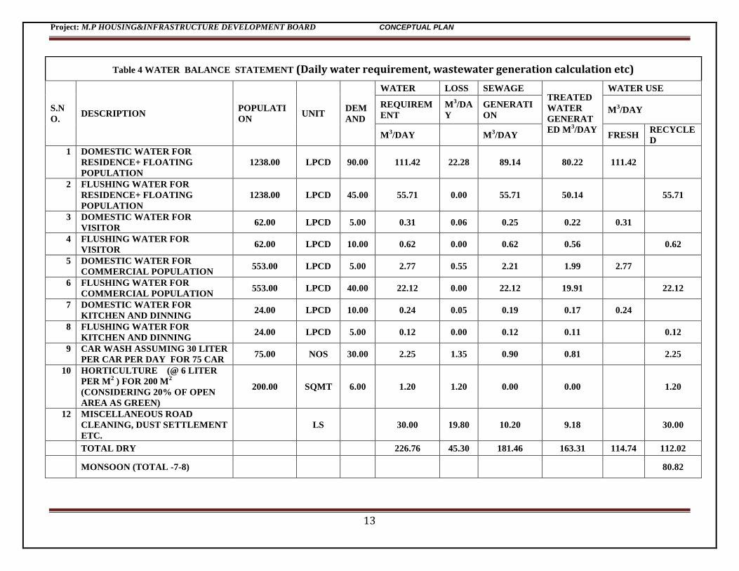
Table 4 WATER BALANCE STATEMENT (Daily water requirement, wastewater generation calculation etc)
S.N
O. DESCRIPTION
POPULATI
ON UNIT
DEM
AND
WATER LOSS SEWAGE TREATED
WATER
GENERAT
ED M3/DAY
WATER USE
REQUIREM
ENT
M3/DA
Y
GENERATI
ON M
3/DAY
M3/DAY M
3/DAY FRESH
RECYCLE
D
1 DOMESTIC WATER FOR
RESIDENCE+ FLOATING
POPULATION
1238.00 LPCD 90.00 111.42 22.28 89.14 80.22 111.42
2 FLUSHING WATER FOR
RESIDENCE+ FLOATING
POPULATION
1238.00 LPCD 45.00 55.71 0.00 55.71 50.14
55.71
3 DOMESTIC WATER FOR
VISITOR 62.00 LPCD 5.00 0.31 0.06 0.25 0.22 0.31
4 FLUSHING WATER FOR
VISITOR 62.00 LPCD 10.00 0.62 0.00 0.62 0.56
0.62
5 DOMESTIC WATER FOR
COMMERCIAL POPULATION 553.00 LPCD 5.00 2.77 0.55 2.21 1.99 2.77
6 FLUSHING WATER FOR
COMMERCIAL POPULATION 553.00 LPCD 40.00 22.12 0.00 22.12 19.91
22.12
7 DOMESTIC WATER FOR
KITCHEN AND DINNING 24.00 LPCD 10.00 0.24 0.05 0.19 0.17 0.24
8 FLUSHING WATER FOR
KITCHEN AND DINNING 24.00 LPCD 5.00 0.12 0.00 0.12 0.11
0.12
9 CAR WASH ASSUMING 30 LITER
PER CAR PER DAY FOR 75 CAR 75.00 NOS 30.00 2.25 1.35 0.90 0.81
2.25
10 HORTICULTURE (@ 6 LITER
PER M2 ) FOR 200 M
2
(CONSIDERING 20% OF OPEN
AREA AS GREEN)
200.00 SQMT 6.00 1.20 1.20 0.00 0.00
1.20
12 MISCELLANEOUS ROAD
CLEANING, DUST SETTLEMENT
ETC.
LS
30.00 19.80 10.20 9.18
30.00
TOTAL DRY
226.76 45.30 181.46 163.31 114.74 112.02
MONSOON (TOTAL -7-8)
80.82
Project: M.P HOUSING&INFRASTRUCTURE DEVELOPMENT BOARD CONCEPTUAL PLAN
14
2.1 SOURCE OF WATER
227 Cum water is required per day. 115 Cum fresh water is required per day. This can be obtain
from existing Municipal system. The required NOC certificate has been procured by the
proponent from Indore Municipal corporation given below.
Annexure-1 : NOC for Water Supply from Indore Municipal Corporation
2.2 WATER TREATMENT SYSTEM
Total sewage generation from the proposed project activity will be 180KLD. The sewage
generated during the operation phase will be treated up to the tertiary level in a STP setup
Project: M.P HOUSING&INFRASTRUCTURE DEVELOPMENT BOARD CONCEPTUAL PLAN
15
proposed in the site having capacity of 220KLD. The treated sewage is recycled/ reused for toilet
flushing and horticulture in the project site. The proponent has been obtained NOC for disposal
of treated wastewater by Indore Municipal Corporation given below.
Annexure-2 : NOC for sewerage disposal from Indore Municipal Corporation
Project: M.P HOUSING&INFRASTRUCTURE DEVELOPMENT BOARD CONCEPTUAL PLAN
16
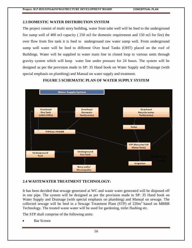
2.3 DOMESTIC WATER DISTRIBUTION SYSTEM
The project consist of multi story building, water from tube well will be feed to the underground
fire sump well of 400 m3 capacity ( 250 m3 for domestic requirement and 150 m3 for fire) the
over flow from fire tank it is feed to underground raw water sump well. From underground
sump well water will be feed to different Over head Tanks (OHT) placed on the roof of
Buildings. Water will be supplied to water main line in closed loop to various units through
gravity system which will keep water line under pressure for 24 hours. The system will be
designed as per the provision made in SP: 35 Hand book on Water Supply and Drainage (with
special emphasis on plumbing) and Manual on water supply and treatment.
FIGURE 5 SCHEMATIC PLAN OF WATER SUPPLY SYSTEM
SEWAGE
AND
2.4 WASTEWATER TREATMENT TECHNOLOGY:
It has been decided that sewage generated at WC and waste water generated will be disposed off
in one pipe. The system will be designed as per the provision made in SP: 35 Hand book on
Water Supply and Drainage (with special emphasis on plumbing) and Manual on sewage. The
collected sewage will be feed in a Sewage Treatment Plant (STP) of 220m3
based on MBBR
Technology. The treated waste water will be used for gardening, toilet flushing etc.
The STP shall comprise of the following units:
Bar Screen
Project: M.P HOUSING&INFRASTRUCTURE DEVELOPMENT BOARD CONCEPTUAL PLAN
17
Grit chamber
Equalization tank
Aeration tank
MBBR Bioreactor
Secondary classifier
Chlorine contact tank
Sludge holding tank
Pressure sand filter
Activated carbon filter.
RAW WATER SEWAGE CHARACTERISTICS
Tentative raw sewage characteristics are mentioned below, however the actual characteristic may vary widely as per site conditions. The bidders are requested to make their judgment for design of system. pH : 5.5 to 8.5 BOD (mg/l) : 150-350 COD (mg/l) : 250-600 Suspended solid (mg/l ) : 200-400 Oil & grease (mg/l) : 20-30
TREATED WATER CHARACTERISTIC General characteristics of treated water will be as below or as per pollution control board norms BOD : Less than 10 mg/l COD : Less than 50 mg/l Suspended Solid : Less than 10 mg/l Oil & grease : Less than 5 mg/l pH : 6.5 -7.5 Bio-assay test : Survival of fish after 96 hrs 100 %
Project: M.P HOUSING&INFRASTRUCTURE DEVELOPMENT BOARD CONCEPTUAL PLAN
18
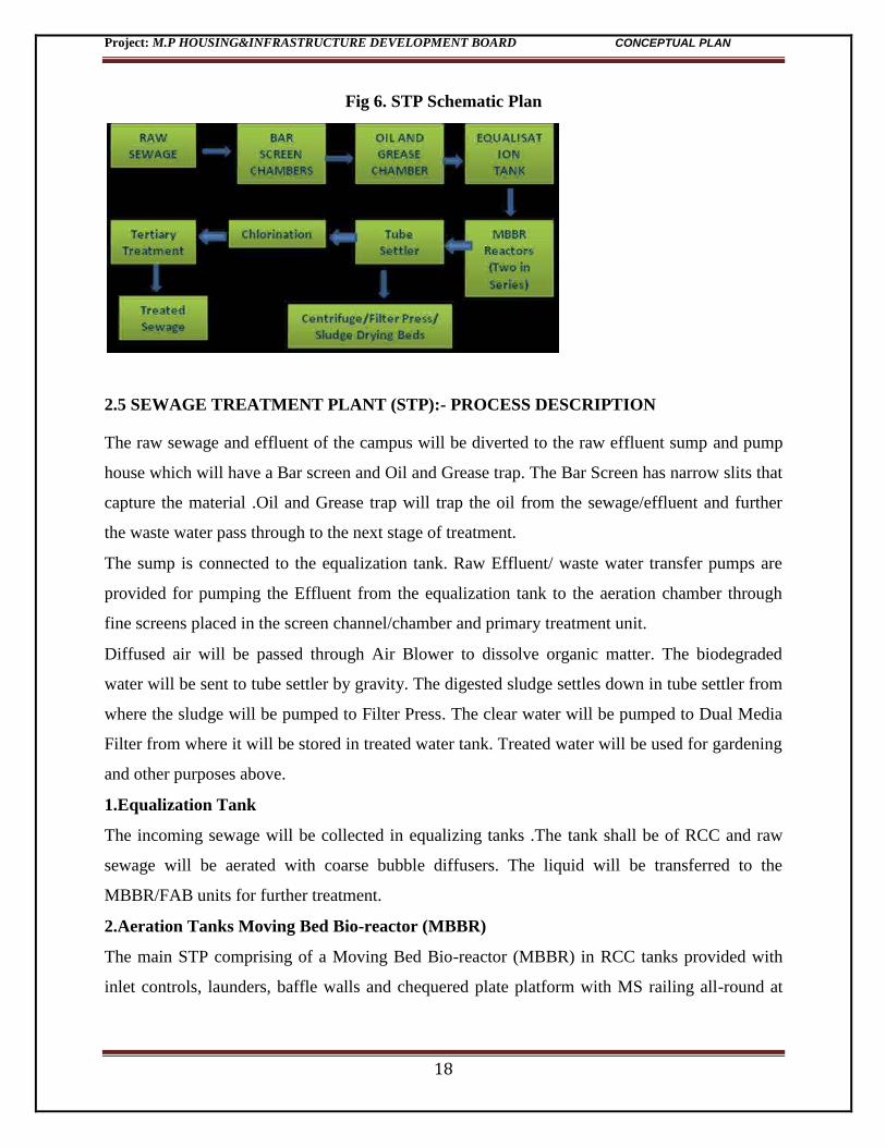
Fig 6. STP Schematic Plan
2.5 SEWAGE TREATMENT PLANT (STP):- PROCESS DESCRIPTION
The raw sewage and effluent of the campus will be diverted to the raw effluent sump and pump
house which will have a Bar screen and Oil and Grease trap. The Bar Screen has narrow slits that
capture the material .Oil and Grease trap will trap the oil from the sewage/effluent and further
the waste water pass through to the next stage of treatment.
The sump is connected to the equalization tank. Raw Effluent/ waste water transfer pumps are
provided for pumping the Effluent from the equalization tank to the aeration chamber through
fine screens placed in the screen channel/chamber and primary treatment unit.
Diffused air will be passed through Air Blower to dissolve organic matter. The biodegraded
water will be sent to tube settler by gravity. The digested sludge settles down in tube settler from
where the sludge will be pumped to Filter Press. The clear water will be pumped to Dual Media
Filter from where it will be stored in treated water tank. Treated water will be used for gardening
and other purposes above.
1.Equalization Tank
The incoming sewage will be collected in equalizing tanks .The tank shall be of RCC and raw
sewage will be aerated with coarse bubble diffusers. The liquid will be transferred to the
MBBR/FAB units for further treatment.
2.Aeration Tanks Moving Bed Bio-reactor (MBBR)
The main STP comprising of a Moving Bed Bio-reactor (MBBR) in RCC tanks provided with
inlet controls, launders, baffle walls and chequered plate platform with MS railing all-round at
Project: M.P HOUSING&INFRASTRUCTURE DEVELOPMENT BOARD CONCEPTUAL PLAN
19
top and a ladders at convenient locations. The units will have required quantity of HDPE media.
The reactors will be aerated as specified below.
3.Aeration
Following units will be aerated with air supplied from common air lowers Equalization Tank
with coarse bubble diffusers. MBBR treatment units with fine bubble diffusers Sludge holding
tanks with coarse bubble diffusers
The aeration will be done by air blowers of required capacity to be based on contractor's design
and kept in pump house as indicated on the tender drawing.
4.Settling Tanks
Aerated sludge in MBBR units will be settled in tube settlers using PVC tubes media. Settled
sludge will be transferred to the sludge holding tank for further disposal.
5.Tertiary Treatment of effluent
The chlorinated/oxidant effluent will be filtered in pressure filter using multi grade sand gravel
filter media and Activated carbon filter and final treated effluent will be collected in final
effluent RCC tank.
The final effluent will then be pumped to the point of re-use for horticultural operation, HVAC
and use in flushing, gardening Excess flow, if any from the STP shall be disposed off by
pumping into the natural or municipal drainage system.
6.Sludge Holding Tank
Sludge from the settling tanks shall be transferred to a sludge holding tank. The tank will be
aerated by means of coarse air bubble diffusers system for thickening and disposal through
pumps. (The sludge holding tank shall be constructed in RCC).
7.Excess sludge disposals
Excess sludge from the sludge holding tank will be pumped and further treated in centrifuge to
increase its consistency in order to produce cakes to be used as soil conditioner as per the
directions of the Engineer-in-Charge.
EXTERNAL SEWERAGE
Sewage lines will be laid along the natural slope of ground with a self cleansing design velocity
of 0.75mtr. /sec. Minimum 150mm dia. RCC NP2 pipe will be provided with a slope as
indicated in drawing.
Project: M.P HOUSING&INFRASTRUCTURE DEVELOPMENT BOARD CONCEPTUAL PLAN
20
2.6 STORM WATER DRAINAGE AND RAIN WATER HARVESTING
The maximum rain fall intensity of rain fall in the area is 63mm per hour terrace will be provided
with 1 % slope toward down pipe by ridges & valleys. uPVC down pipe class III 6 kg/cm2
conforming to IS 4985 will be used as per National Building Code 2005 Table No. 28 Part 9
Page 70. Rain water from terrace of buildings, paved areas and road surface will be collected and
harvested as per standard norms. The procedures followed for rain water harvesting is as per the
systems and procedures given by “Rain Water Harvesting and Conservation Manual” – Govt.,
of India , CPWD, New Delhi.( June 2002).Suitable number of rain
water harvest pits will be provided along the road side drain to
recharge the ground water.
Storm water drainage system will be design at a maximum
intensity of 100mm per hour with run off coefficient as under:
Roof &hard paved surface : 80%
Lawn / Non paved area : 40%
The storm water lines will be design having a Self Cleansing
velocity of 0.60mtr./sec.
2.7 WATER CONSERVATION
Following system / fixtures are provided to reduce/control the water consumption of the
complex.
1. Providing dual flushing cistern for water closet 3 -6 litres in place of 10 litres cistern.
2. Consumption requirement of fresh water will be reduced by 70 % by using –
a. Drip irrigation for horticultural plants.
b Planting plants which require less water reduction up to 40%
c. Air cooled air conditioning in place of water cooling system consumption requirement
of fresh water will be reduced by 70% by using.
Project: M.P HOUSING&INFRASTRUCTURE DEVELOPMENT BOARD CONCEPTUAL PLAN
21
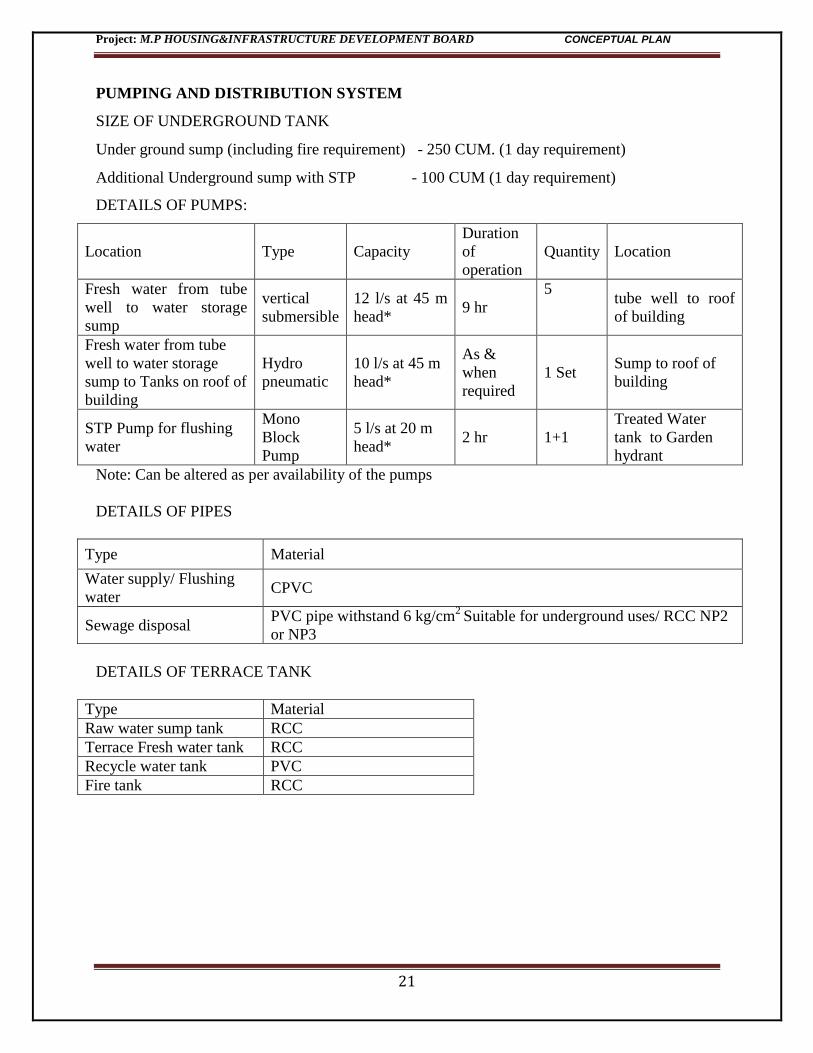
PUMPING AND DISTRIBUTION SYSTEM
SIZE OF UNDERGROUND TANK
Under ground sump (including fire requirement) - 250 CUM. (1 day requirement)
Additional Underground sump with STP - 100 CUM (1 day requirement)
DETAILS OF PUMPS:
Location Type Capacity
Duration
of
operation
Quantity Location
Fresh water from tube
well to water storage
sump
vertical
submersible
12 l/s at 45 m
head* 9 hr
5
tube well to roof
of building
Fresh water from tube
well to water storage
sump to Tanks on roof of
building
Hydro
pneumatic
10 l/s at 45 m
head*
As &
when
required
1 Set Sump to roof of
building
STP Pump for flushing
water
Mono
Block
Pump
5 l/s at 20 m
head* 2 hr 1+1
Treated Water
tank to Garden
hydrant
Note: Can be altered as per availability of the pumps
DETAILS OF PIPES
Type Material
Water supply/ Flushing
water CPVC
Sewage disposal PVC pipe withstand 6 kg/cm
2 Suitable for underground uses/ RCC NP2
or NP3
DETAILS OF TERRACE TANK
Type Material
Raw water sump tank RCC
Terrace Fresh water tank RCC
Recycle water tank PVC
Fire tank RCC
Project: M.P HOUSING&INFRASTRUCTURE DEVELOPMENT BOARD CONCEPTUAL PLAN
22
3.0 SOLID WASTE COLLECTION / DISPOSAL PLAN
Solid waste would be generated both during the construction as well as during the operation
phase. The solid waste expected to be generated during the construction phase will comprise of
excavated materials, used bags, bricks, concrete, MS rods, tiles, wood etc. The following steps
are to be followed for the management solid waste:
Construction yards for storage of construction materials.
The excavated material such as topsoil and stones will be stacked for reuse during later
stages of construction
Excavated top soil will be stored in temporary constructed soil bank and will be reused
for landscaping of the township project.
Remaining soil shall be utilized for refilling / road work / rising of site level at locations/
selling to outside agency for construction of roads etc.
The operations phase of the project the refuse generation rate as 0.5kg/Capita/day for residents,
0.25 Kg/Capita/day for staff and 0.15 Kg/Capita/day for visitors have been considered.
Collection systems comprise waste containers at ground floor of the building. The solid waste
shall be disposed to the appropriate site as per municipal authority. The generated solid waste
shall be first segregated as plastic, glass, paper and other waste separately and disposed off as per
MSW Rules, 2000. The inert solid waste will be transported to a govt. designated landfill site.
Table 5. SOLID WASTE GENERATION:
Solid Waste Calculation
Sl No. Description Occupancy kg/capita/day Total solid waste
generated in kg/day
a Residential 1238 0.5 619
B Commercial 577 0.25 144
C Visitors 62 0.15 9
D e-waste 1238 0.18 223
Total solid waste generated 996
Bio degradable 20% 199
Recyclable 70% 698
Inert 10% 99
Total 996
Project: M.P HOUSING&INFRASTRUCTURE DEVELOPMENT BOARD CONCEPTUAL PLAN
23
Bio-Degradable waste
Bio-degradable waste will be collected in the secondary processing area and fed to an
Organic Convertor the compost will be used as manure.
STP sludge is to be used for horticultural purposes as manure.
Horticultural Waste is to be composted and will be used for gardening purposes.
Recyclable waste
The segregated recyclable waste will be sold off to vendors
Inert waste
The inert waste collected at site will be sent to landfill through the municipal waste
handling system
MP Housing and Infrastructure Development Corporation has been procured NOC for the
disposal of solid waste that will be generated from the proposed construction site on operation.
It has been given below.
Annexure -3 NOC for Solid Waste Disposal
Project: M.P HOUSING&INFRASTRUCTURE DEVELOPMENT BOARD CONCEPTUAL PLAN
24
4.0 POWER REQUIREMENT, ELECTRICAL, BUILDING & FIRE
SAFETY ,DG SETS DETAILS :
4.1 GENERAL:
The Proposed commercial and residential building at HOPE, Indore mainly consists of
following major areas:-
a) Commercial building:- APPAREL PARK
b) Residential building:-BLOCK-A, BLOCK-B
Associated amenities are being provided with building.
4.2 DESIGN STANDARDS & CODES:
Electrical system design shall be in confirmation to the requirement of:
Indian Electricity Rule 1956.
Standards & Code Practice of Bureau of Indian Standard for various equipments &
Systems.
National Building Code of India -2005 (Part -8)
National Electricity Code of India
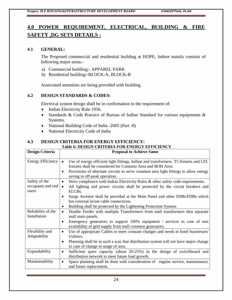
4.3 DESIGN CRITERIA FOR ENERGY EFFICIENCY: Table 6: DESIGN CRITERIA FOR ENERGY EFFICIENCY
Design Criteria Proposal to Achieve Same
Energy Efficiency Use of energy efficient light fittings, ballast and transformers. T5 fixtures and CFL
fixtures shall be considered for Common Area and BOH Area.
Provisions of alternate circuits to serve common area light fittings to allow energy
saving in off-peak operation.
Safety of the
occupants and end
users
Strict compliance with Indian Electricity Rules & other safety code requirements.
All lighting and power circuits shall be protected by the circuit breakers and
ELCBs.
Surge Arrestor shall be provided at the Main Panel and other SDBs/FDBs which
has external in/out cable connections.
Building shall be protected by the Lightening Protection System.
Reliability of the
Installation Double Feeder with multiple Transformers from mall transformers thru separate
mall main panels.
Emergency generators to support 100% equipment / services in case of non
availability of grid supply from mall common generators.
Flexibility and
Adaptability Use of appropriate Cables to meet constant changes and needs in hotel businesses/
Utilities.
Planning shall be in such a way that distribution system will not have major change
in case of change in usage of area.
Expandability Sufficient spare capacity (about 20-25%) in the design of switchboard and
distribution network to meet future load growth.
Maintainability Space planning shall be done with consideration of regular service, maintenance;
and future replacement.
Project: M.P HOUSING&INFRASTRUCTURE DEVELOPMENT BOARD CONCEPTUAL PLAN
25
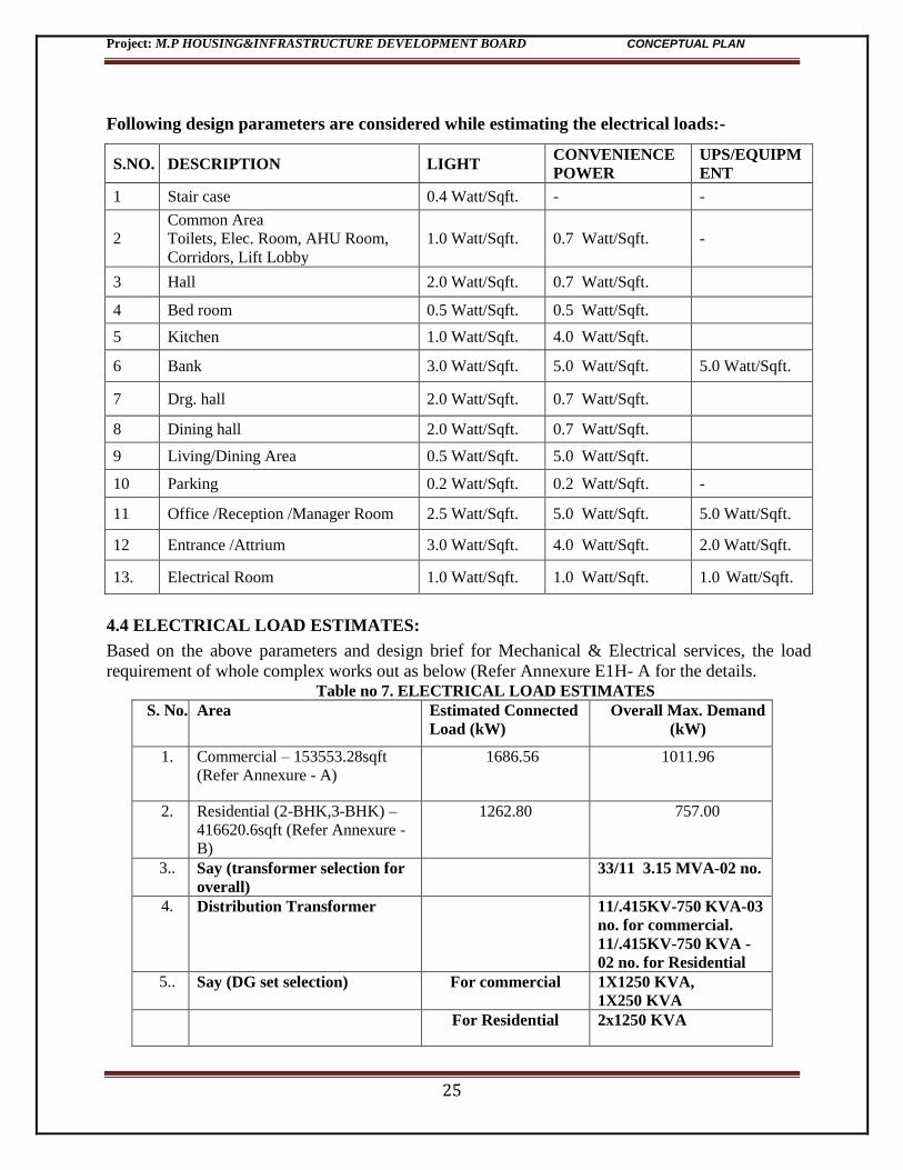
Following design parameters are considered while estimating the electrical loads:-
S.NO. DESCRIPTION LIGHT CONVENIENCE
POWER
UPS/EQUIPM
ENT
1 Stair case 0.4 Watt/Sqft. - -
2
Common Area
Toilets, Elec. Room, AHU Room,
Corridors, Lift Lobby
1.0 Watt/Sqft. 0.7 Watt/Sqft. -
3 Hall 2.0 Watt/Sqft. 0.7 Watt/Sqft.
4 Bed room 0.5 Watt/Sqft. 0.5 Watt/Sqft.
5 Kitchen 1.0 Watt/Sqft. 4.0 Watt/Sqft.
6 Bank 3.0 Watt/Sqft. 5.0 Watt/Sqft. 5.0 Watt/Sqft.
7 Drg. hall 2.0 Watt/Sqft. 0.7 Watt/Sqft.
8 Dining hall 2.0 Watt/Sqft. 0.7 Watt/Sqft.
9 Living/Dining Area 0.5 Watt/Sqft. 5.0 Watt/Sqft.
10 Parking 0.2 Watt/Sqft. 0.2 Watt/Sqft. -
11 Office /Reception /Manager Room 2.5 Watt/Sqft. 5.0 Watt/Sqft. 5.0 Watt/Sqft.
12 Entrance /Attrium 3.0 Watt/Sqft. 4.0 Watt/Sqft. 2.0 Watt/Sqft.
13. Electrical Room 1.0 Watt/Sqft. 1.0 Watt/Sqft. 1.0 Watt/Sqft.
4.4 ELECTRICAL LOAD ESTIMATES:
Based on the above parameters and design brief for Mechanical & Electrical services, the load
requirement of whole complex works out as below (Refer Annexure E1H- A for the details. Table no 7. ELECTRICAL LOAD ESTIMATES
S. No. Area Estimated Connected
Load (kW)
Overall Max. Demand
(kW)
1. Commercial – 153553.28sqft
(Refer Annexure - A)
1686.56 1011.96
2. Residential (2-BHK,3-BHK) –
416620.6sqft (Refer Annexure -
B)
1262.80 757.00
3.. Say (transformer selection for
overall)
33/11 3.15 MVA-02 no.
4. Distribution Transformer 11/.415KV-750 KVA-03
no. for commercial.
11/.415KV-750 KVA -
02 no. for Residential
5.. Say (DG set selection) For commercial 1X1250 KVA,
1X250 KVA
For Residential 2x1250 KVA
Project: M.P HOUSING&INFRASTRUCTURE DEVELOPMENT BOARD CONCEPTUAL PLAN
26
4.5 Source of Power:-
Overall maximum demand is for commercial building approximately 1011.96 KW. Or 1124.40
KVA at power factor 0.90, Power for commercial building shall be available at 415v voltage level
common 11/0.415 KV substation.
And overall maximum demand is for residential building approximately 757KW. or 841.11 KVA
at power factor 0.90, Power for residential building shall be available at 415v voltage level
common 11/0.415 KV substation
Supply to Commercial building & Residential building shall be brought through underground HT,
XLPE cables terminated at 33 KV Switchgear. However, the outgoings of 11KV switchgears shall
be provided with multifunction meter for required metering in the Commercial building &
Residential building premises of project. The billing from MPSEB shall be on single point basis
and submitting charges shall be collected from individual commercial & resident (by sub meter)
spaces by building management team.
4.5.1 33/11kv Sub Stations:-
33 KV Power supply from MPSEB will be brought by 100 % rated 33 KV feeders at
Outdoor Switch Yard.
a) Substation consisting of 33 KV HT Substation, Oil type Transformers & HT Breaker
(VCB at desired amp. Capacity) are planned at Outdoor Service Yard. An option of
alternative location is also suggested which needs approval from client.
Based on the Load Calculations, Transformers of 2x3.15 MVA Capacity are installed.
4.5.2 11kv/0.415 Volt Sub Stations:-
11KV Power supply from 33kv HT yard will be brought by 100 % rated, 11 KV feeders at
Outdoor Switch Yard..
b) Substation consisting of 11 KV LT Substation, Oil type Transformers & LT Breaker
(VCB at desired capacity) are planned at Outdoor Service Yard. An option of
alternative location is also suggested which needs approval from client.
Based on the Load Calculations, Transformers of 3x750 KVA (for commercial) and
2x750
KVA (for residential) Capacity are installed.
4.6 BACKUP POWER SUPPLY:-
80% Power backup is planned for the situation when normal power supply is not available. DG
Sets of 415 Volt are proposed in the DG Plant Room at nearby substation. As per the load
calculations, the DG Sets of 1 x 250 KVA, 3X1250 KVA capacities are required. All DG Sets
Project: M.P HOUSING&INFRASTRUCTURE DEVELOPMENT BOARD CONCEPTUAL PLAN
27
shall have heat exchanger and silent type with canopy water cooled with AMF panel planned.
Main panel for commercial and residential (above the commercial building) has feeds from
transformers of (3x750kva) and for separate residential block feeds from one transformer
(2x750kva.)
DG Plant Room shall be acoustically treated to arrest the noise pollution as per CPCB Norm.
Exhaust piping for the DG Sets shall be taken up to the highest point as per CPCB guidelines.
Power is reliable in Indore where site is located therefore continuous operation of DG Sets may not
arrive.
4.7 LANDSCAPE
The green belt design along the periphery of the plot is planned to achieve attenuation factor
confirming to the day and night noise standards prescribed for residential land use. The open
spaces inside the plot will be landscaped. Total green area proposed will be 33% of the total plot
area. Only native vegetation with a mix of evergreen and deciduous trees shall be utilized to
maintain seasonal greenery inside the complex in addition to flowering and ornamental plants.
Project: M.P HOUSING&INFRASTRUCTURE DEVELOPMENT BOARD CONCEPTUAL PLAN
28
5.0 FIRE FIGHTING SYSTEM :
No Objection Certificate from State Disaster Response and Fire services Department will be
obtained for the proposed building and conditions of the same shall be complied.
The Building Plans in respect of high rise building is in two parts, one part is Residence Building
& other part is for Apparel Park at Indore. The same have been examined from Life & Fire
Safety and Means of Escape point of and for making provision and execution of the scheme
conforming to NBC PART – IV and other relevant Codes, Bye-Laws of Madhya Pradesh Govt.
BRIEF ABOUT: APPAREL PARK:
No. of Floors - Apparel Park. : Ground + 6 Floors.
No. of Basement : 1 No.
No. of Lifts : 3 No.
No. of Staircase : 3 No.
Total Height of Apparel Park : 24 Mtr.
Total Basement Area Apparel Park : 3892.30Sqmtr
Floor Area of Apparel Park : Approx 1468.00 Sqmtr.
Refuge Area : After 18 Mtr.
M.O.S. : 6 Mtr. wide clear approaches in 7.50 m MOS.
BRIEF ABOUT: RESIDENTIAL BUILDING
No. of Floors : Stilt + 14 Floors. + Service Floor
No. of Basement : 2 Nos.
No. of Lifts : 2 Nos. (Each block)
No. of Staircase : 1 Nos. (Each block)
Total Height : 42 Mtr. (Excluding stilt floor & service floor)
Refuge Area : After 18 Mtr.
M.O.S. : 6 Mtr. wide clear approach in 7.50 m MOS.
Total Basement Area Apparel Park : 9411.59 Sqmtr
BOTH APPAREL PARK & RESIDENTIAL BUILDING SHALL BE PROTECTED
WITH THE FOLLOWING SYSTEM:
01. Hose reel system connected with overhead & underground water tank.
02. Wet riser system connected with overhead & under ground water tank.
03. Yard hydrant connected with overhead & under ground water tank.
04. Automatic Sprinkler system.
05. Automatic Smoke Detection \ emergency Fire Alarm System.
Project: M.P HOUSING&INFRASTRUCTURE DEVELOPMENT BOARD CONCEPTUAL PLAN
29
06. Fire Extinguishers of different category & capacity.
07. Fire Staircase/Exit.
08. Fireman switch in lift.
09. Earthling Conductor.
10. Fire Control room.
11. Overhead water tank.
12. Underground water tank.
13. Emergency & Escape Lighting.
14. Basement.
15. Exit & Travel Distance.
16. Corridors & Passageways.
17. Fire Doors.
18. Travel distance to Safe Area.
19. Refuge Area.
System Designed are as per: NBC Part IV (Fire & Life Safety)
According to NBC, Project this falls under :
Group F with Sub-division F-2 & Group A With Sub-division A-5
As per NBC Part 4- Fire Fighting System required as under:-
Fire Extinguishers
Hose Reel
Wet Riser
Yard Hydrants
Pressurization of Enclosed Staircase
Lift Lobby
Fire Doors
Automatic Smoke Detection \Fire Alarm System
Automatic Sprinkler System the Basement Plan.
Underground Static Water Storage Tank
Terrace Tank
Pump near Underground Static Water Storage Tank
5.1 FIRE FIGHTING SYSTEM DESCRIPTION
Hose reel- Wet riser- Yard Hydrant for Both Apparel Park & Residential Building
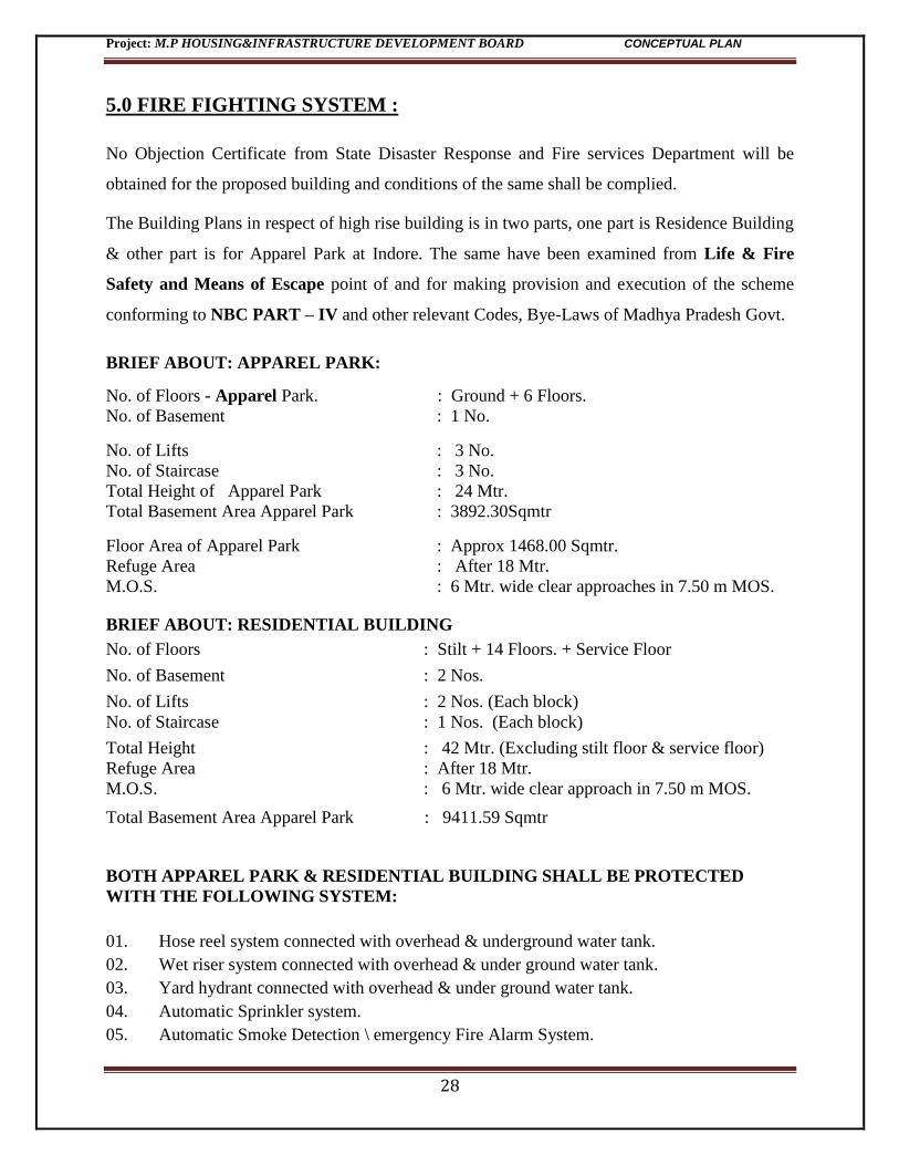
In BOTH BUILDINGS the Wet riser/Hydrant & Hose Reels system will be connected through
M S “C” class pipe Line at each floor along with basement and ground floor area. The pipe line
sizes will be respectively from 250 mm dia to 80 mm dia with NRV, gate valves / ball valves
Project: M.P HOUSING&INFRASTRUCTURE DEVELOPMENT BOARD CONCEPTUAL PLAN
30
including fittings like Tee, Sockets, Bends, Flanges, special design fire hydrant valves, hose reel
etc.; these pipe lines will be connected with main header of through Pump with M.S. “C” class
pipe with Underground Water Tanks as well as with overhead tank. Wherever necessary a 4 mm
thick water proof coating membrane has to be applied on underground pipes at Maximum at 1.2
Mt Depth.
A suitable pumps of 137m3/hr as a main pump of 88 Meter WC Head has to be connected with
the said system at ground level for whole buildings as well as Jockey pump of 10.8 m3/hr of
88Meter WC Head for pressuring the system for RESIDENTIAL Building.
A suitable pumps of 137m3/hr as a main pump of 88 Meter WC Head has to be connected with
the said system at ground level for whole buildings as well as Jockey pump of 10.8 m3/hr of 88
Meter WC Head for pressuring the system for APPAREL PARK.
These BOTH BUILDING pumps will be connected with their individual electrical supply panel
having a manual or auto change over either by MPEB or by DG set, so that at any hour the
electrical supply shall be provided to the said pump at any cost. This system will also be
connected with one fire brigade supply connection for an emergency (in case if specifically
stored water was consumed or used in case of an emergency). One similar capacity of diesel
pump set will be installed as a standby for both premises separately. There is also draw out
connection for taking water in case of emergency when pump fail to suck the water.
Similarly a yard hydrant at equal distance, around the both the
building will have to be provided. This system will be interlinked
with wet riser system also.
Pl. Note: Minimum one set of hydrant valve constructed in Gun
Metal/SS having ISI mark, Hose box, Hoses, Shutoff nozzle and hose
reel of 30 Mtr. Length will be installed at each floor area.
Project: M.P HOUSING&INFRASTRUCTURE DEVELOPMENT BOARD CONCEPTUAL PLAN
31
5.2 SPRINKLER SYSTEM
Refer Annexure – I Table – 23 NBC
FOR Apparel Park Suitable pumps of 137m3/hr as a Sprinkler pump of 80 Meter WC Head has
to be connected with the said system. The Sprinkler system is only for the common Basement
Parking area, for Club Hotel area and also to be provide in the Ground to Forth Floor Hall Area .
It will be provided with pipes sizes having dia from 25 mm to 150 mm dia & all fittings like tee,
sprinkler alarm valve with gong bell ,control valves, draining & testing assembly Butterfly
valves etc. These sprinklers will be such distributed & so designs and installed that it will cover
complete enclosed area of all floors from Ground to Fourth Floor , to the Hall area & Basement.
Flexible drop will be used in Sprinklers wherever the false ceiling will come for better fixation of
Sprinkler.
For Residential BUILDING separate pump for Sprinkler system is not required & Sprinkler
system will be provided in the basement parking area. It will be provided with pipes sizes
having dia from 25 mm to 150 mm dia & all fittings like tee, sprinkler alarm valve with gong
bell ,control valves, draining & testing assembly Butterfly valves etc. Also Sprinkler Alarm
Valve to be provided in Sprinkler line to distinguish the fire in the basement area. Sprinkler will
be distributed as per 3mtr spacing on both side, so that it will cover all the area of basement.
Project: M.P HOUSING&INFRASTRUCTURE DEVELOPMENT BOARD CONCEPTUAL PLAN
32
Refer Annexure – I Table – 23 NBC
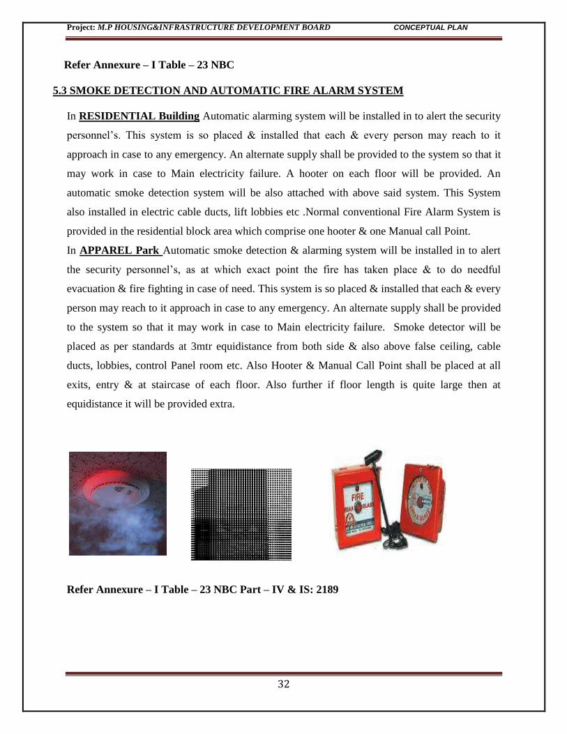
5.3 SMOKE DETECTION AND AUTOMATIC FIRE ALARM SYSTEM
In RESIDENTIAL Building Automatic alarming system will be installed in to alert the security
personnel’s. This system is so placed & installed that each & every person may reach to it
approach in case to any emergency. An alternate supply shall be provided to the system so that it
may work in case to Main electricity failure. A hooter on each floor will be provided. An
automatic smoke detection system will be also attached with above said system. This System
also installed in electric cable ducts, lift lobbies etc .Normal conventional Fire Alarm System is
provided in the residential block area which comprise one hooter & one Manual call Point.
In APPAREL Park Automatic smoke detection & alarming system will be installed in to alert
the security personnel’s, as at which exact point the fire has taken place & to do needful
evacuation & fire fighting in case of need. This system is so placed & installed that each & every
person may reach to it approach in case to any emergency. An alternate supply shall be provided
to the system so that it may work in case to Main electricity failure. Smoke detector will be
placed as per standards at 3mtr equidistance from both side & also above false ceiling, cable
ducts, lobbies, control Panel room etc. Also Hooter & Manual Call Point shall be placed at all
exits, entry & at staircase of each floor. Also further if floor length is quite large then at
equidistance it will be provided extra.
Refer Annexure – I Table – 23 NBC Part – IV & IS: 2189
Project: M.P HOUSING&INFRASTRUCTURE DEVELOPMENT BOARD CONCEPTUAL PLAN
33
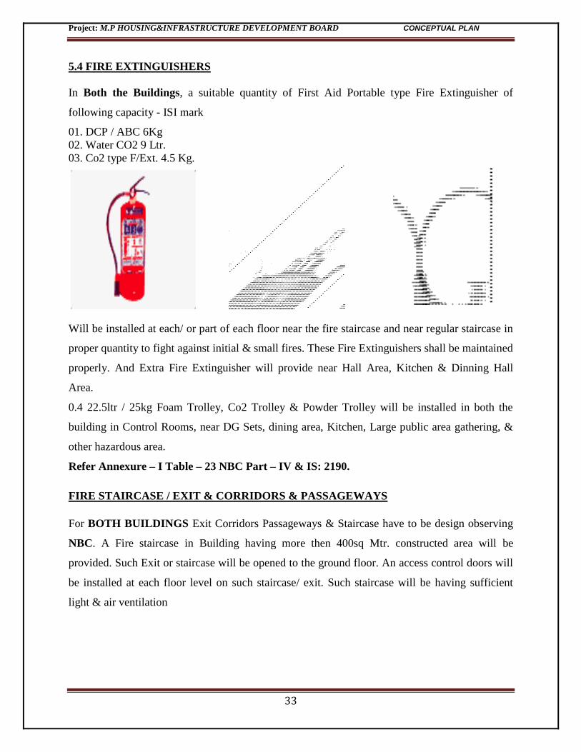
5.4 FIRE EXTINGUISHERS
In Both the Buildings, a suitable quantity of First Aid Portable type Fire Extinguisher of
following capacity - ISI mark
01. DCP / ABC 6Kg
02. Water CO2 9 Ltr.
03. Co2 type F/Ext. 4.5 Kg.
Will be installed at each/ or part of each floor near the fire staircase and near regular staircase in
proper quantity to fight against initial & small fires. These Fire Extinguishers shall be maintained
properly. And Extra Fire Extinguisher will provide near Hall Area, Kitchen & Dinning Hall
Area.
0.4 22.5ltr / 25kg Foam Trolley, Co2 Trolley & Powder Trolley will be installed in both the
building in Control Rooms, near DG Sets, dining area, Kitchen, Large public area gathering, &
other hazardous area.
Refer Annexure – I Table – 23 NBC Part – IV & IS: 2190.
FIRE STAIRCASE / EXIT & CORRIDORS & PASSAGEWAYS
For BOTH BUILDINGS Exit Corridors Passageways & Staircase have to be design observing
NBC. A Fire staircase in Building having more then 400sq Mtr. constructed area will be
provided. Such Exit or staircase will be opened to the ground floor. An access control doors will
be installed at each floor level on such staircase/ exit. Such staircase will be having sufficient
light & air ventilation
Project: M.P HOUSING&INFRASTRUCTURE DEVELOPMENT BOARD CONCEPTUAL PLAN
34
.
Refer Annexure – I Clause - 4.8, 4.9 NBC Part – IV & IS: 2190.
EXITS / TRAVEL DISTANCE
Adequate provision of Exits on all floors as per NBC Part - IV for this category of occupancy
have been made to meet Life Safety needs matching the prescribed Travel Distance requirements
leading to place of Safety.
Refer Annexure – I Clause – 4.2, 4.63 Table 21, 22, Clause 6.4 NBC Part – IV.
FIRE LIFTS
In Both buildings Two Fire Lifts for every
floor for minimum 6 passengers is to be
provided. Lift should be conforming to the
fire safety standards having solid doors
along with an alternate source of supply with
firemen switch and having fire rating of 2
hour’s is compulsory.
Refer Annexure – I Clause 4.15 NBC Part – IV
EARTHING CONDUCTOR
In Both Building Copper earthing conductor shall be provided by electrical agency. This
conductor will be earth with the help of a suitable armoured cable at ground floor with proper
earthing material.
Project: M.P HOUSING&INFRASTRUCTURE DEVELOPMENT BOARD CONCEPTUAL PLAN
35
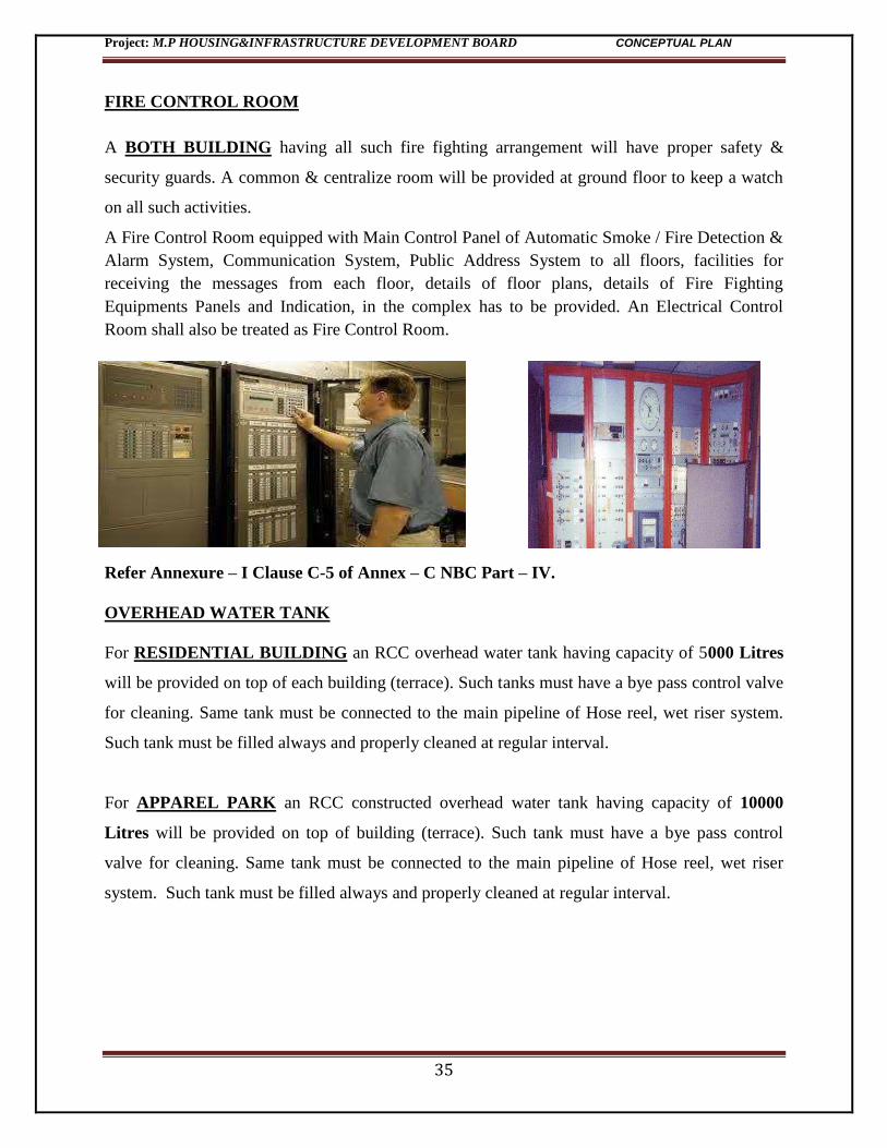
FIRE CONTROL ROOM
A BOTH BUILDING having all such fire fighting arrangement will have proper safety &
security guards. A common & centralize room will be provided at ground floor to keep a watch
on all such activities.
A Fire Control Room equipped with Main Control Panel of Automatic Smoke / Fire Detection &
Alarm System, Communication System, Public Address System to all floors, facilities for
receiving the messages from each floor, details of floor plans, details of Fire Fighting
Equipments Panels and Indication, in the complex has to be provided. An Electrical Control
Room shall also be treated as Fire Control Room.
Refer Annexure – I Clause C-5 of Annex – C NBC Part – IV.
OVERHEAD WATER TANK
For RESIDENTIAL BUILDING an RCC overhead water tank having capacity of 5000 Litres
will be provided on top of each building (terrace). Such tanks must have a bye pass control valve
for cleaning. Same tank must be connected to the main pipeline of Hose reel, wet riser system.
Such tank must be filled always and properly cleaned at regular interval.
For APPAREL PARK an RCC constructed overhead water tank having capacity of 10000
Litres will be provided on top of building (terrace). Such tank must have a bye pass control
valve for cleaning. Same tank must be connected to the main pipeline of Hose reel, wet riser
system. Such tank must be filled always and properly cleaned at regular interval.
Project: M.P HOUSING&INFRASTRUCTURE DEVELOPMENT BOARD CONCEPTUAL PLAN
36
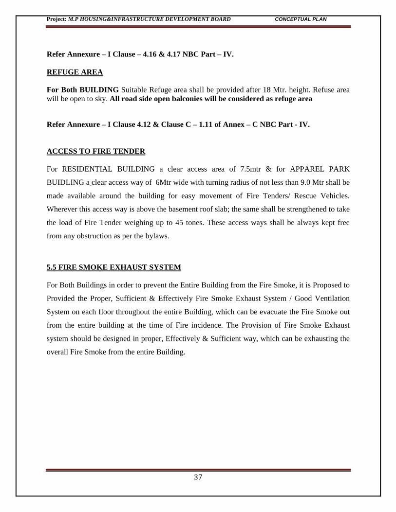
UNDERGROUND WATER TANK
For both BUILDING an RCC / PCC underground water tank of capacity 1.75 Lacs Litres will
be provide at ground/ basement level having two equal parts with common sump and control
valves. Such sump and control valves are provided for repairing and maintenance of the either
side of the tank.
At any case such tank will not be kept empty. In case of maintenance it is mandatory that one
part of the tank will be kept filled always.
All the above said wet riser, sprinkler, yard hydrant; hose reel system will be connected through
pump with this tank.
Refer Annexure – I Table 23 NBC Part – IV & IS: 9668.
EMERGENCY & ESCAPE LIGHTING
FOR BOTH BUILDING Emergency lighting powered from independent source capable of
indicating clearly the escape routes & exit points and identifies the MCP’s & Fire Fighting
Equipments.
Project: M.P HOUSING&INFRASTRUCTURE DEVELOPMENT BOARD CONCEPTUAL PLAN
37
Refer Annexure – I Clause – 4.16 & 4.17 NBC Part – IV.
REFUGE AREA
For Both BUILDING Suitable Refuge area shall be provided after 18 Mtr. height. Refuse area
will be open to sky. All road side open balconies will be considered as refuge area
Refer Annexure – I Clause 4.12 & Clause C – 1.11 of Annex – C NBC Part - IV.
ACCESS TO FIRE TENDER
For RESIDENTIAL BUILDING a clear access area of 7.5mtr & for APPAREL PARK
BUIDLING a clear access way of 6Mtr wide with turning radius of not less than 9.0 Mtr shall be
made available around the building for easy movement of Fire Tenders/ Rescue Vehicles.
Wherever this access way is above the basement roof slab; the same shall be strengthened to take
the load of Fire Tender weighing up to 45 tones. These access ways shall be always kept free
from any obstruction as per the bylaws.
5.5 FIRE SMOKE EXHAUST SYSTEM
For Both Buildings in order to prevent the Entire Building from the Fire Smoke, it is Proposed to
Provided the Proper, Sufficient & Effectively Fire Smoke Exhaust System / Good Ventilation
System on each floor throughout the entire Building, which can be evacuate the Fire Smoke out
from the entire building at the time of Fire incidence. The Provision of Fire Smoke Exhaust
system should be designed in proper, Effectively & Sufficient way, which can be exhausting the
overall Fire Smoke from the entire Building.
Project: M.P HOUSING&INFRASTRUCTURE DEVELOPMENT BOARD CONCEPTUAL PLAN
38
6.0 PROJECT MONITORING
Pollution monitoring program includes periodic analysis of air, ground water, soil and wastewater
samples. Ground water and soil samples at representative locations within and nearby the project
site will be periodically analyzed to detect contamination if any.
In the event of any contamination, concerned authorities will be intimated immediately and
appropriate corrective action in consultation with an approved technical agency will be initiated.
6.1 MONITORING STRATEGY
The monitoring of various environmental parameters is necessary and is a part and parcel of the
environmental protection measures. Monitoring is as important as that of control of pollution
since the efficiency of control measures can only be determined by monitoring.
A well-defined environmental monitoring program would be employed to monitor the
environmental attributes to check whether they maintained within the permissible limits.
The following Environmental attributes would be monitored:
Air pollution and meteorological aspects
Water and waste water quality
Noise levels
Soil characteristics
Ecological preservation and up gradation
Maintenance of water conservation methods
Maintenance & operation of STP
Locations and frequency of monitoring would be as per the guidelines of MPPCB/CPCB and
MOEF.
6.2 Ambient Air Monitoring
As per MOEF there is a need to identify 3 ambient air stations at 120o angle keeping the main
source in the center. The ground level concentrations of suspended particulate, sulphur dioxide
and nitrogen oxides in the ambient air outside the project boundaries and in the adjoining areas
will be monitored at regular intervals. Any deviation from predicted/expected values will be
investigated and necessary action will be taken.
Project: M.P HOUSING&INFRASTRUCTURE DEVELOPMENT BOARD CONCEPTUAL PLAN
39
6.3 Noise Monitoring
Noise levels in the complex will be monitored periodically. If any deviation is observed necessary
corrective measures will be taken.
Monitoring noise levels is essential to assess the efficacy of maintenance of schedules undertaken
to reduce noise levels and noise protection measures. A good quality sound pressure level meter is
essential for this purpose. Noise surveillance is for the benefit of the well being of residents and to
keep track of sources.
6.4 Water Quality Monitoring
Ground water near the project site will be routinely tested for its quality. No contamination of
ground water and surface water is expected. However the water will be periodically tested for
any change of water quality.
The effluents/sewage coming out of the complex should be monitored regularly. Ground water is
recommended to be monitored in at least two points in the direction of ground water flow to keep
surveillance on the ground water quality.
6.5 Sewage Treatment Plant
The operations of STP are monitored to ensure the quality of treated water and discharge of waste
water into municipal sewage system. The de-silting of sludge on regular basis needs to be
ensured.
6.6 BUDGET FOR EMP:
The details of activities and expenses to be incurred on EMP are presented below.
Table no.8 EMP Budget
The recurring expenditure includes maintenance of green area & landscape, monitoring of
environmental attributes and maintenance & operation of STP and rain harvesting system.
S.No. Component Amount
Rs Lakhs
1 STP & Rainwater Harvesting 100
2 Green Belt Development 35
3 Monitoring 10
Total 145
Recurring Expenditure 25
Project: M.P HOUSING&INFRASTRUCTURE DEVELOPMENT BOARD CONCEPTUAL PLAN
40
The budget for the components of EMP will be a part of project cost while the recurring
expenditure will be met from the maintenance charges collected from residents on monthly basis.
Implementation
The Environmental Management will be implemented by the project promoters through a
responsible in charge person, appointed exclusively for the purpose, with the help of assistants.
6.7 ENVIRONMENT MANAGEMENT PLAN
Environmental Management Plan (EMP) is the key to ensure a safe and clean environment. The
desired results from the environmental mitigation measures proposed in the project may not be
obtained without a management plan to assure its proper implementation & function. The EMP
envisages the plans for the proper implementation of mitigation measures to reduce the adverse
impacts arising out of the project activities. EMP has been prepared addressing the issues like:
• Pollution control/mitigation measures for abatement of the undesirable impacts caused during
the construction and operation stage
• Institutional set up identified/recommended for implementation of the EMP
• Post project environmental monitoring programme to be undertaken
• Expenditures for environmental protection measures and budget for EMP
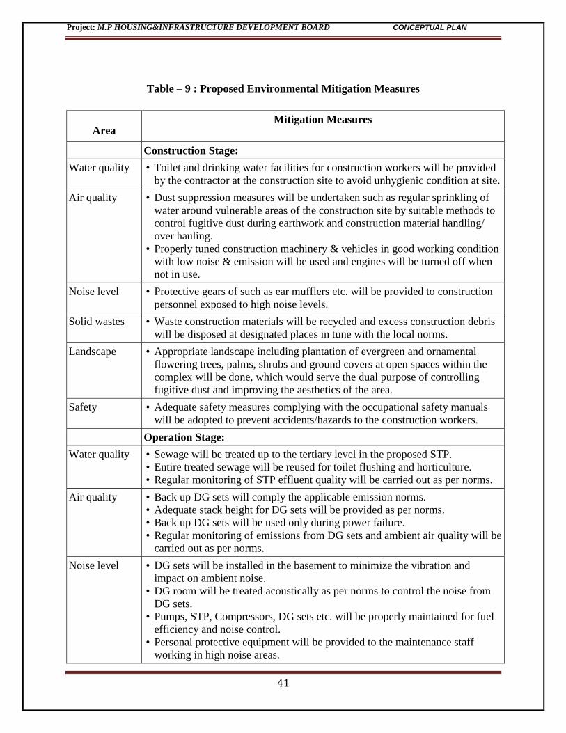
Proposed Environmental Mitigation Measures
These measures together constitute part of Environmental Management Plan (EMP). The
environmental mitigation measures for construction and operation phases has been given in
Table – 6.1.
Project: M.P HOUSING&INFRASTRUCTURE DEVELOPMENT BOARD CONCEPTUAL PLAN
41
Table – 9 : Proposed Environmental Mitigation Measures
Area Mitigation Measures
Construction Stage:
Water quality • Toilet and drinking water facilities for construction workers will be provided
by the contractor at the construction site to avoid unhygienic condition at site.
Air quality • Dust suppression measures will be undertaken such as regular sprinkling of
water around vulnerable areas of the construction site by suitable methods to
control fugitive dust during earthwork and construction material handling/
over hauling.
• Properly tuned construction machinery & vehicles in good working condition
with low noise & emission will be used and engines will be turned off when
not in use.
Noise level • Protective gears of such as ear mufflers etc. will be provided to construction
personnel exposed to high noise levels.
Solid wastes • Waste construction materials will be recycled and excess construction debris
will be disposed at designated places in tune with the local norms.
Landscape • Appropriate landscape including plantation of evergreen and ornamental
flowering trees, palms, shrubs and ground covers at open spaces within the
complex will be done, which would serve the dual purpose of controlling
fugitive dust and improving the aesthetics of the area.
Safety • Adequate safety measures complying with the occupational safety manuals
will be adopted to prevent accidents/hazards to the construction workers.
Operation Stage:
Water quality • Sewage will be treated up to the tertiary level in the proposed STP.
• Entire treated sewage will be reused for toilet flushing and horticulture.
• Regular monitoring of STP effluent quality will be carried out as per norms.
Air quality • Back up DG sets will comply the applicable emission norms.
• Adequate stack height for DG sets will be provided as per norms.
• Back up DG sets will be used only during power failure.
• Regular monitoring of emissions from DG sets and ambient air quality will be
carried out as per norms.
Noise level • DG sets will be installed in the basement to minimize the vibration and
impact on ambient noise.
• DG room will be treated acoustically as per norms to control the noise from
DG sets.
• Pumps, STP, Compressors, DG sets etc. will be properly maintained for fuel
efficiency and noise control.
• Personal protective equipment will be provided to the maintenance staff
working in high noise areas.
Project: M.P HOUSING&INFRASTRUCTURE DEVELOPMENT BOARD CONCEPTUAL PLAN
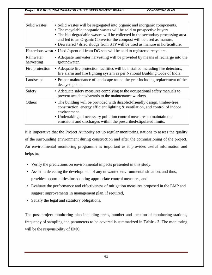
42
Solid wastes • Solid wastes will be segregated into organic and inorganic components.
• The recyclable inorganic wastes will be sold to prospective buyers.
• The bio-degradable wastes will be collected in the secondary processing area
and fed to an Organic Convertor the compost will be used as manure.
• Dewatered / dried sludge from STP will be used as manure in horticulture.
Hazardous waste • Used / spent oil from DG sets will be sold to registered recyclers.
Rainwater
harvesting
• Adequate rainwater harvesting will be provided by means of recharge into the
groundwater.
Fire protection • Adequate fire protection facilities will be installed including fire detectors,
fire alarm and fire fighting system as per National Building Code of India.
Landscape • Proper maintenance of landscape round the year including replacement of the
decayed plants.
Safety • Adequate safety measures complying to the occupational safety manuals to
prevent accidents/hazards to the maintenance workers.
Others • The building will be provided with disabled-friendly design, timber-free
construction, energy efficient lighting & ventilation, and control of indoor
environment.
• Undertaking all necessary pollution control measures to maintain the
emissions and discharges within the prescribed/stipulated limits.
It is imperative that the Project Authority set up regular monitoring stations to assess the quality
of the surrounding environment during construction and after the commissioning of the project.
An environmental monitoring programme is important as it provides useful information and
helps to:
• Verify the predictions on environmental impacts presented in this study,
• Assist in detecting the development of any unwanted environmental situation, and thus,
provides opportunities for adopting appropriate control measures, and
• Evaluate the performance and effectiveness of mitigation measures proposed in the EMP and
suggest improvements in management plan, if required,
• Satisfy the legal and statutory obligations.
The post project monitoring plan including areas, number and location of monitoring stations,
frequency of sampling and parameters to be covered is summarized in Table - 2. The monitoring
will be the responsibility of EMC.
Project: M.P HOUSING&INFRASTRUCTURE DEVELOPMENT BOARD CONCEPTUAL PLAN
43
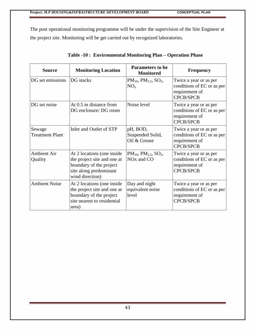
The post operational monitoring programme will be under the supervision of the Site Engineer at
the project site. Monitoring will be get carried out by recognized laboratories.
Table -10 : Environmental Monitoring Plan – Operation Phase
Source Monitoring Location Parameters to be
Monitored Frequency
DG set emissions DG stacks PM10, PM2.5, SO2,
NOx
Twice a year or as per
conditions of EC or as per
requirement of
CPCB/SPCB
DG set noise At 0.5 m distance from
DG enclosure/ DG room
Noise level Twice a year or as per
conditions of EC or as per
requirement of
CPCB/SPCB
Sewage
Treatment Plant
Inlet and Outlet of STP pH, BOD,
Suspended Solid,
Oil & Grease
Twice a year or as per
conditions of EC or as per
requirement of
CPCB/SPCB
Ambient Air
Quality
At 2 locations (one inside
the project site and one at
boundary of the project
site along predominant
wind direction)
PM10, PM2.5, SO2,
NOx and CO
Twice a year or as per
conditions of EC or as per
requirement of
CPCB/SPCB
Ambient Noise At 2 locations (one inside
the project site and one at
boundary of the project
site nearest to residential
area)
Day and night
equivalent noise
level
Twice a year or as per
conditions of EC or as per
requirement of
CPCB/SPCB
Project: M.P HOUSING&INFRASTRUCTURE DEVELOPMENT BOARD CONCEPTUAL PLAN
44
6.8 Environment Management Cell
The composition of the Environment Management Cell and responsibilities of its various
members are given in Table – 6.3.
Table -11 : Environment Management Cell
S. No Level & Person Proposed Responsibility
1. Corporate Level:
Environment
Department
• Environmental policy and directions
• Overall responsibility for environment management and decision
making for all environmental issues
• Ensuring legal compliance and interaction with regulatory
agencies
2. Project Level
(Construction):
Site In-charge
• Environmental management & pollution control during
construction stage
• Installation of pollution control facilities and implementation of
the conditions of Environmental Clearance and Consent to
Establish
• Environmental monitoring during construction stage
• Secondary responsibility for ensuring legal compliance during
construction stage
3. Project Level
(Operation):
Building Manager
• Environmental management and operation & maintenance of
pollution control facilities during operation stage
• Environmental monitoring during operation stage
• Secondary responsibility for environment management and
decision making for all environmental issues
• Secondary responsibility for ensuring legal compliance and
interaction with regulatory agencies during operation stage