clean development mechanism project design document … biomass energy... · clean development...
TRANSCRIPT

PROJECT DESIGN DOCUMENT FORM (CDM-SSC-PDD) - Version 03 CDM – Executive Board
1
CLEAN DEVELOPMENT MECHANISM PROJECT DESIGN DOCUMENT FORM (CDM-SSC-PDD)
Version 03 - in effect as of: 22 December 2006
CONTENTS A. General description of the small scale project activity B. Application of a baseline and monitoring methodology C. Duration of the project activity / crediting period D. Environmental impacts E. Stakeholders’ comments
Annexes Annex 1: Contact information on participants in the proposed small scale project activity Annex 2: Information regarding public funding Annex 3: Baseline information
Annex 4: Monitoring Information
PROJECT DESIGN DOCUMENT FORM (CDM-SSC-PDD) - Version 03 CDM – Executive Board
2
Revision history of this document Version Number
Date Description and reason of revision
01 21 January 2003
Initial adoption
02 8 July 2005 • The Board agreed to revise the CDM SSC PDD to reflect guidance and clarifications provided by the Board since version 01 of this document.
• As a consequence, the guidelines for completing CDM SSC PDD have been revised accordingly to version 2. The latest version can be found at <http://cdm.unfccc.int/Reference/Documents>.
03 22 December 2006
• The Board agreed to revise the CDM project design document for small-scale activities (CDM-SSC-PDD), taking into account CDM-PDD and CDM-NM.

PROJECT DESIGN DOCUMENT FORM (CDM-SSC-PDD) - Version 03 CDM – Executive Board
3
SECTION A. General description of small-scale project activity A.1 Title of the small-scale project activity: GEPL Biomass energy generation project at Faridabad, Haryana Version: 1.0 Date: 08/08/2007 A.2. Description of the small-scale project activity: The project activity consists of biomass based energy generation in the textile processing division of Gupta Exim (India) Pvt. Ltd (GEPL) at village Prithla, Tehsil Palwal in Faridabad, Haryana. The project activity is being carried out in two phases. The first phase entails the installation of a boiler to generate steam by combustion of biomass, thereby doing away with the use of coal for process heating, installation of one thermopac for heat generation for stenters and relax drier in the plant. The second phase consists of installation of a cogeneration unit (a new boiler and matching steam turbine are proposed) for the simultaneous production of steam and electricity. The boiler installed in the first phase will be used as a stand by, once the second phase is completed and commissioned. GEPL, a government recognized export house is part of the multifaceted group, having diversified interests. The company is engaged in the manufacturing and export of knitted cotton and woollen garments. Biomass (rice husk) will be used to generate power and steam for use within the plant premises. Details of Project Activity
Thermal Energy
Electrical Power Equipments in the Project Activity
Remarks
Steam generation in Boiler based on Renewable Biomass
HSEB1 grid power
Boiler 01 No. (Boiler No 1) Capacity = 10 TPH Pressure = 11.25 kg/cm2 (g) Temp. = 188 Deg C
Commissioned in September 2006
Phase I Heat generation2 in Thermic Fluid Heater based on Renewable Biomass
HSEB grid power
Thermopac of 2.0 million kcal/hour capacity
Commissioned in September 2006
Phase II
Renewable Biomass based
Renewable Biomass based
Boiler 01 No. (Boiler No. 2) Capacity = 20 TPH Pressure = 66 kg/cm2 Temp. = 490 Deg C
Expected commissioning by December 2008
1 HSEB: Haryana State Electricity Board 2 In case of non-availability of biomass fired boiler during shutdown/ breakdown, thermopac can also be used along with thermic steam generator for steam generation required in the process heating

PROJECT DESIGN DOCUMENT FORM (CDM-SSC-PDD) - Version 03 CDM – Executive Board
4
Turbine Capacity = 3 MW Type = Extraction-condensing turbine3
Expected commissioning by December 2008
The project activity reduces greenhouse gas emissions by avoiding fossil fuel combustion in steam and power generation. In the absence of project activity, GEPL would have installed a coal based energy generation unit and/ or continued withdrawal of power from the state grid, which is primarily based on fossil fuel combustion (Project activity is located in the state of Haryana, which is part of Northern Region Grid in India. The Grid Emission Factor of Northern Region Grid is 0.80tCO2e/MWh4). It is a carbon neutral project activity as the greenhouse gases generated during the process are of biogenic origin. Sustainable Development by the project activity The project activity will contribute towards the Government of India’s sustainable development criteria in the following manner: 1. The project activity will lead to overall development of the region, and will improve the rural economy. The use of biomass will provide an additional source of income for the rural community. Setting up of collection and delivery points will also generate employment for the local people.
2. It will generate employment opportunities for the skilled as well as unskilled labour during the construction, and operation phase of the project.
3. The project activity would help to reduce the demand-supply gap in power deficit regional grid.
4. This will provide necessary impetus for industries to come up with more such projects in the area
5. Since the project activity utilizes biomass as fuel, it helps in conservation of natural resources such as coal, natural gas etc.
6. The project activity is carbon neutral as the CO2 generated during combustion of fuel is taken up by the biomass for its growth.
7. The technology used in the project activity is indigenous and safe.
3 Steam extraction from the turbine would be used in process heating and the only steam boiler installed in phase I of project activity would be used as standby to the cogeneration unit. 4 CEA data on grid emission factor, http://www.cea.nic.in/planning/c%20and%20e/user_guide_ver2.pdf

PROJECT DESIGN DOCUMENT FORM (CDM-SSC-PDD) - Version 03 CDM – Executive Board
5
A.3. Project participants:
Name of Party involved (*) ((host) indicates a host involved)
Private and/or public entity(ies) Project Participants(*) (as applicable)
Party involved wishes to be considered as project participant (Yes/No)
India (host) Gupta Exim (India) Pvt. Limited (private entity) No
A.4. Technical description of the small-scale project activity: A.4.1. Location of the small-scale project activity: A.4.1.1. Host Party(ies): India A.4.1.2. Region/State/Province etc.: State: Haryana A.4.1.3. City/Town/Community etc: District: Faridabad Village: Prithla A.4.1.4. Details of physical location, including information allowing the unique identification of this small-scale project activity : The project activity is located on Chhaprola Road, village Prithla, on the Delhi- Agra Highway. It is situated approximately 20 km away from the nearest railway station, Ballabhgarh and the nearest airport is Indira Gandhi International Airport, New Delhi. It is geographically located between 28.42 N Latitude and 77.30 E Longitude. The physical address of the project site: Gupta Exim (India) Pvt. Limited Chhaprola Road, Village Prithla Tehsil Palwal, Distt. Faridabad Haryana, India Phone: 91-129-4090400 The map below shows the geographical location.

PROJECT DESIGN DOCUMENT FORM (CDM-SSC-PDD) - Version 03 CDM – Executive Board
6
Location Map of Project Site – Gupta Exim Pvt. Limited

PROJECT DESIGN DOCUMENT FORM (CDM-SSC-PDD) - Version 03 CDM – Executive Board
7
A.4.2. Type and category(ies) and technology/measure of the small-scale project activity:Main Category: Type I – Renewable Energy Projects Sub Category: AMS I C – Thermal energy for user with or without electricity Version 11, Scope 1 (EB 32) Technology of Project Activity: The following systems are part of the project boundary and constitute the biomass fired boiler, thermic fluid generator and the proposed cogeneration unit, metering and monitoring systems. Phase I: It constitutes energy generation using biomass. GEPL has installed a steam boiler and one thermopac along with one thermic fluid steam generator in this phase, the description of which is given below. Boiler: Parameter Details Boiler Model MTFH 100A Boiler Rated Capacity (MCR) 10 TPH Pressure (safety valve set) 11.25 kg/cm2(g)Temperature 188 °C Thermic fluid steam generator is a shell and tube type heat exchanger having horizontal orientation. Parameter Details Steam Output F & A 100 0 C 2000 kg/hr Design Pressure 10.54 kg/cm2g Safety Valve Set Pressure 10.54 kg/cm2g Heat Output 1.08x10⁶ kcal/hr Thermic Fluid Flow Rate 58 m3/hr
Thermic Fluid Inlet/Outlet temperature 270 / 230 deg C
Thermopac: The thermopac has an overhead feeding system for biomass consisting of a screw feeder provided along with a feeding hopper. The specifications are as listed below:
Parameters Details
Heater model VTAF-20
Heater output 2,000,000 kcal/hr
Maximum thermic fluid outlet temp. 280oC
Thermal oil flow 150 m3/hr
PROJECT DESIGN DOCUMENT FORM (CDM-SSC-PDD) - Version 03 CDM – Executive Board
8
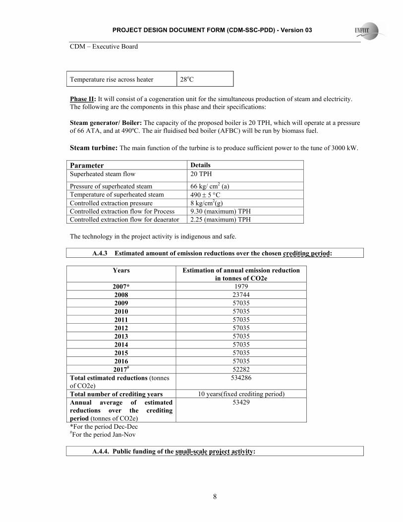
Temperature rise across heater 28oC
Phase II: It will consist of a cogeneration unit for the simultaneous production of steam and electricity. The following are the components in this phase and their specifications: Steam generator/ Boiler: The capacity of the proposed boiler is 20 TPH, which will operate at a pressure of 66 ATA, and at 490ºC. The air fluidised bed boiler (AFBC) will be run by biomass fuel. Steam turbine: The main function of the turbine is to produce sufficient power to the tune of 3000 kW. Parameter Details Superheated steam flow 20 TPH
Pressure of superheated steam 66 kg/ cm2 (a) Temperature of superheated steam 490 ± 5 °C Controlled extraction pressure 8 kg/cm2(g) Controlled extraction flow for Process 9.30 (maximum) TPH Controlled extraction flow for deaerator 2.25 (maximum) TPH The technology in the project activity is indigenous and safe.
A.4.3 Estimated amount of emission reductions over the chosen crediting period:
Years Estimation of annual emission reduction in tonnes of CO2e
2007* 1979 2008 23744 2009 57035 2010 57035 2011 57035 2012 57035 2013 57035 2014 57035 2015 57035 2016 57035 2017# 52282
Total estimated reductions (tonnes of CO2e)
534286
Total number of crediting years 10 years(fixed crediting period) Annual average of estimated reductions over the crediting period (tonnes of CO2e)
53429
*For the period Dec-Dec #For the period Jan-Nov A.4.4. Public funding of the small-scale project activity:
PROJECT DESIGN DOCUMENT FORM (CDM-SSC-PDD) - Version 03 CDM – Executive Board
9
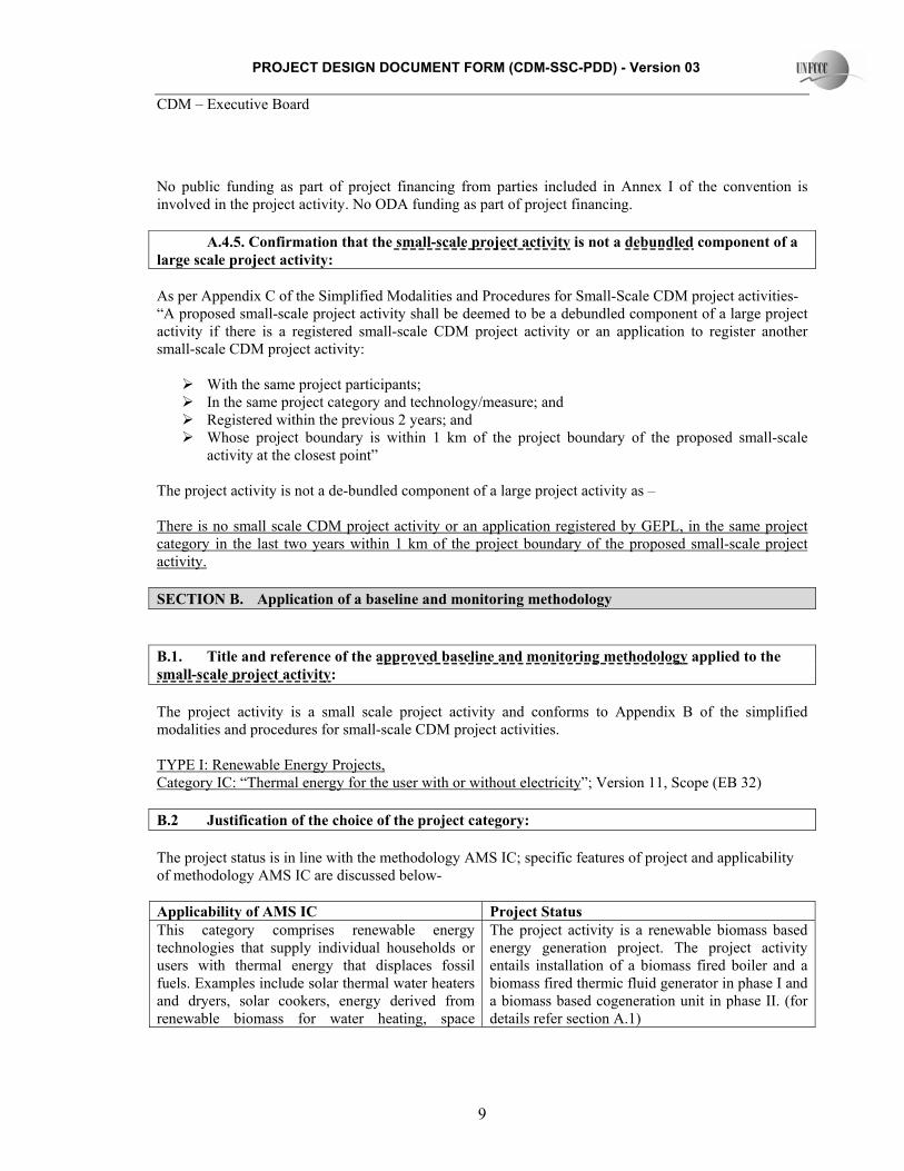
No public funding as part of project financing from parties included in Annex I of the convention is involved in the project activity. No ODA funding as part of project financing. A.4.5. Confirmation that the small-scale project activity is not a debundled component of a large scale project activity: As per Appendix C of the Simplified Modalities and Procedures for Small-Scale CDM project activities- “A proposed small-scale project activity shall be deemed to be a debundled component of a large project activity if there is a registered small-scale CDM project activity or an application to register another small-scale CDM project activity:
With the same project participants; In the same project category and technology/measure; and Registered within the previous 2 years; and Whose project boundary is within 1 km of the project boundary of the proposed small-scale
activity at the closest point” The project activity is not a de-bundled component of a large project activity as – There is no small scale CDM project activity or an application registered by GEPL, in the same project category in the last two years within 1 km of the project boundary of the proposed small-scale project activity. SECTION B. Application of a baseline and monitoring methodology B.1. Title and reference of the approved baseline and monitoring methodology applied to the small-scale project activity: The project activity is a small scale project activity and conforms to Appendix B of the simplified modalities and procedures for small-scale CDM project activities. TYPE I: Renewable Energy Projects, Category IC: “Thermal energy for the user with or without electricity”; Version 11, Scope (EB 32) B.2 Justification of the choice of the project category: The project status is in line with the methodology AMS IC; specific features of project and applicability of methodology AMS IC are discussed below- Applicability of AMS IC Project Status This category comprises renewable energy technologies that supply individual households or users with thermal energy that displaces fossil fuels. Examples include solar thermal water heaters and dryers, solar cookers, energy derived from renewable biomass for water heating, space
The project activity is a renewable biomass based energy generation project. The project activity entails installation of a biomass fired boiler and a biomass fired thermic fluid generator in phase I and a biomass based cogeneration unit in phase II. (for details refer section A.1)

PROJECT DESIGN DOCUMENT FORM (CDM-SSC-PDD) - Version 03 CDM – Executive Board
10
heating, or drying, and other technologies that provide thermal energy that displaces fossil fuel. Biomass-based co-generating systems that produce heat and electricity are included in this category. Where thermal generation capacity is specified by the manufacturer, it shall be less than 45 MW.
The thermal generation capacity of the project activity is less than 45 MW.5
For co-fired systems the aggregate installed capacity (specified for fossil fuel use) of all systems affected by the project activity shall not exceed 45 MWth. Cogeneration projects that displace/ avoid fossil fuel consumption in the production of thermal energy (e.g. steam or process heat) and/or electricity shall use this methodology. The capacity of the project in this case shall be the thermal energy production capacity i.e. 45 MWth.
The thermal generation capacity of the project activity is less than 45 MW.
In the case of project activities that involve the addition of renewable energy units at an existing renewable energy facility, the total capacity of the units added by the project should be lower than 45 MWth and should be physically distinct2 from the existing units.
The project activity is a green field project from PP and it is not an extension of an existing renewable energy project.
B.3. Description of the project boundary: The project boundary comprises of the following:
• Power generation equipment which includes boilers, thermopac, thermic fluid generator, steam turbine and metering equipments.
• Fuel storage It is illustrated in the diagram given below:
5 The cumulative installed capacity of thermal energy output for the equipments in the project activity is ~26 MW (6.5 MW for boiler, 2.5 MW for the thermopac in phase I and ~16.5 MW for the boiler proposed in Phase II.

PROJECT DESIGN DOCUMENT FORM (CDM-SSC-PDD) - Version 03 CDM – Executive Board
11
Phase I
Phase II
B.4. Description of baseline and its development: Approved methodology AMS IC has been applied to the project activity as it meets applicability criteria outlined in the methodology. Following paragraphs demonstrate selection of baseline scenario out of the various alternatives available to the project proponent. Identification of alternative baseline scenarios: The methodology as applied to the project activity involves the identification of alternative baseline scenarios that provide or produce electricity/ steam for in-house consumption. The possible alternative baseline scenarios are as follows: Alternative 1: Import of electricity from grid and steam is produced onsite using fossil fuels This alternative considers generation of equivalent amount of electricity in grid in the absence of the project activity and onsite generation of steam in a coal fired boiler. Alternative 2: Electricity and steam are produced onsite using fossil fuel in a cogeneration unit The second alternative is to produce both electricity as well as steam at the project site using coal.
Project boundary
Biomass storage
Boiler A
Thermopac Steam
generation
Thermic fluid steam generator
Biomass source
Emissions generated
Emissions sequestered
Emissions sequestered
Emissions generated
Biomass (Rice husk) storage
Boiler B
Steam Turbine
Steam
Power
Electricity and steam supply to textile plant
Steam

PROJECT DESIGN DOCUMENT FORM (CDM-SSC-PDD) - Version 03 CDM – Executive Board
12
Alternative 3: Electricity and steam are produced onsite using biomass as in the project activity without CDM benefits Alternative 3 faces many barriers and hence can not be a plausible baseline option for energy generation for the project proponent (refer section B.5 of the document for additionality). The other two alternatives are analyzed here for Levelized cost of power and the option with least Levelized cost of unit power generation is taken as baseline option for the project activity. For Alternative 1, power is drawn from the state grid and steam is generated in house using coal while in Alternative 2, cogeneration unit based on coal would have produced both steam and power simultaneously. As steam is extracted in a cogeneration unit from the turbine and it is not possible to dissociate the cost of steam from that of power generated, for analysis it has been assumed that steam cost from Alternative 2 is zero and all the cost is Levelized against power generated in the system. Similarly, for comparison with Alternative 1, again the cost of steam has been Levelized to the cost of power withdrawn from the state grid and effective cost of power is calculated. The comparison of the two power costs would give the least cost option to PP. The assumptions for the calculations considered are as below: Alternative 1: Import of electricity from grid and steam is produced onsite using fossil fuels In this case, GEPL would have gone for installation of a steam boiler solely to meet the process heat demand and would have continued grid power withdrawal from HSEB. Following financial data have been considered for estimation of Levelised cost of this mix of steam and power. Financial parameters: Description Details Remarks The project cost of the stand alone boiler in phase I
Rs. 10.2 million Includes cost of plant & machinery, land, civil, electrical, consultancy and other contingencies. This is considered to be the same as that of the biomass fired boiler installed by GEPL in Phase I.
Debt: equity ratio 70:30 As per the loan documents Interest rate on term loan 8.75% As per the loan documents for the
project activity, same has been considered for Alternative 1
O&M 3.5% Central Electricity Authority data Depreciation rate 4.5% Straight Line Method Insurance Rate 0.75% Coal price Rs.4400/ MT For imported coal of 6000 kcal/ kg
calorific value Technical parameters:

PROJECT DESIGN DOCUMENT FORM (CDM-SSC-PDD) - Version 03 CDM – Executive Board
13
Parameter Details Remarks Boiler Capacity 10 TPH Taken as that of the biomass fired boiler in the
project activity Boiler efficiency 88% Central Electricity Authority data on coal boiler
operations Steam Pressure 11.25 kg/cm2 Taken as that of biomass fired boiler in project
activity Steam Temperature 188 Deg C Taken as that of biomass fired boiler in project
activity Feed water inlet temperature 105 Deg C Taken as that of biomass fired boiler in project
activity Coal calorific value 6000 kcal/ kg For imported coal The Levelized cost of power in Alternative 1 has been estimated in following steps:
1. Estimation of cost of steam generation in coal fired boiler:
2. The steam cost from step 1 is added to the cost of power withdrawal from the grid and then the total cost (steam and power) is weighted against as cost of power considering steam available for no cost. This is done to equate the power cost with that in the Alternative 2.
Alternative 2: Financial parameters: Description Details Remarks The project cost of the cogeneration plant
is ~Rs. 158 million6 Includes cost of plant & machinery, land, civil, electrical, consultancy and other contingencies. This is considered to be the same as that of the biomass fired boiler proposed by GEPL in Phase II.
Debt: equity ratio 70:30 Debt Equity ratio as approved by lenders
Interest rate on term loan 8.75% As per the loan documents for the project activity, same has been considered for Alternative 1
O&M 3.5% Central Electricity Authority data Depreciation rate 4.5% Straight Line Method Insurance Rate 0.75% Coal price Rs.4200/ MT For imported coal of 6000 kcal/ kg
calorific value 6 GEPL in the project activity has installed a biomass fired boiler in phase I only for steam generation as the lead time for cogeneration unit is longer and to meet the immediate captive demand for steam they had to go for this boiler even though this would be kept as standby as soon as the cogeneration unit is commissioned. This is an additional cost in the project activity

PROJECT DESIGN DOCUMENT FORM (CDM-SSC-PDD) - Version 03 CDM – Executive Board
14
Technical parameters: Description Details Remarks Power Generation Capacity 3 MW Project Report Steam Flow at turbine Inlet at rated capacity
19 TPH As per HMBD of proposed cogeneration unit
Boiler efficiency 88% Central Electricity Authority data on coal boiler operations
Calorific value - Coal 6000 kcal/ kg For imported coal The comparison has been carried out for equivalent power generation for the above two options:
Parameter Unit
Annualized cost of power in
Alt 1 - Coal only Steam + power from grid
Annualized cost of power in
Alt 2 - Coal Cogen
Fixed Cost Cost of equity INR (Lacs) 4.3 66 Cost of debt INR (Lacs) 6.2 97 Depreciation cost INR (Lacs) 3.2 50 Insurance cost INR (Lacs) 0.8 8.3 Total Fixed Cost 14.5 221 Variable Cost Cost of fuel INR (Lacs) 322.4 902 Cost of O&M INR (Lacs) 2.5 39 Total Variable Cost 340.3 983 Total Cost (fixed+variable) INR (Lacs) 339.4 1161 Total steam Generation tonnes/annum 72360 72360 Total Generation/ withdrawal from grid MWh 21708 21708
Cost of power withdrawal from grid @ Rs. 4.50/ kWh INR (Lacs) 977 0*
Unit cost of power generation# Rs/kWh 6.06 5.35
*For cogen unit steam cost is taken as zero #Steam cost is transferred to power
As evident from the table above, Levelized cost of power generation for Alternative 1 is more than that in Alternative 2 and hence it can be concluded that Alternative 2 would have been the choice for steam and power generation for the project proponent. In the absence of the project activity, GEPL would have burnt coal for its steam and power requirement for meeting the steam and electricity demand in the cogeneration plant. B.5. Description of how the anthropogenic emissions of GHG by sources are reduced below those that would have occurred in the absence of the registered small-scale CDM project activity:

PROJECT DESIGN DOCUMENT FORM (CDM-SSC-PDD) - Version 03 CDM – Executive Board
15
The project activity is based on renewable biomass fuel (primarily rice-husk) which is GHG neutral. The project activity replaces the use of fossil fuel for steam & power generation. The main driving forces for the project proponent have been:
1. To actively participate in the climate change initiative and thereby contribute in the reduction of GHG emissions
2. To contribute towards the sustainable development of the region and promote such technologies in the region.
Simplified modalities and procedures for small scale CDM project activities guides to establish additionality of the project activity as per Attachment A to Appendix B. The Attachment A to appendix B mentions various barriers and requires explanation to show that the project activity would not have occurred due to at least any one barrier. The following paragraphs explain the additionality rationale: Investment barrier The project activity entails proposed installation of an Atmospheric Fluidized Bed Combustion (AFBC) boiler and an extraction-condensing turbine for steam and power generation. Extracted steam would be utilized for process heating purpose in the unit. The total investment in the project activity is approximately Rs. 158 million. This includes the cost of plant & machinery, civil & electrical works, cost of land, consultancy etc. In this section, we would analyse whether or not the project activity is financially more viable compared to the baseline scenario i.e. a coal fired cogeneration plant. As per a report from Central Electricity Authority on the capital cost requirement for a coal fired power plant would be ~Rs. 40 million per MW, which is less than that in the proposed cogeneration unit, which would further add to the cost of unit power generation. However, in the analysis we have considered the cost of power plant to be same for both the cases. In both the cases, cost of steam extracted has been considered as nil (assuming same performance parameters) and this cost has been weighted against the cost of power generation in the system. Other factors e.g. interest on term loan, debt: equity ratio, insurance, depreciation rate has also been considered to be the same. Following assumptions have been made for the comparison purpose: Financial parameters: Description Details Remarks The project cost of the cogeneration plant
is ~Rs. 158 million Includes cost of plant & machinery, land, civil, electrical, consultancy and other contingencies
Debt: equity ratio 70:30 Interest rate on term loan 8.75% As per the loan documents for the
project activity, same has been considered for Alternative 1
O&M 3.5% Central Electricity Authority data Depreciation rate 4.5% Straight Line Method Insurance Rate 0.75% Technical parameters: Description Details Remarks

PROJECT DESIGN DOCUMENT FORM (CDM-SSC-PDD) - Version 03 CDM – Executive Board
16
Power Generation Capacity 3 MW Project Report Steam Flow at turbine Inlet at rated capacity
19 TPH As per Heat Mass Balance Diagram (HMBD) of proposed cogeneration unit
Boiler efficiency 88% Central Electricity Authority data on coal boiler operations
Calorific value - Coal 6000 kcal/ kg For imported coal Calorific value – Rice Husk 3000 kcal/ kg As is basis Based on the values above, the comparison has been carried out for equivalent power generation for the above two options:
Parameter Unit Annualized
cost of power in Alt 2 - Coal Cogen
Annualized cost of power in – Project Activity
Fixed Cost Cost of equity INR (Lacs) 66 66 Cost of debt INR (Lacs) 97 97 Depreciation cost INR (Lacs) 50 50 Insurance cost INR (Lacs) 8.3 8.3 Total Fixed Cost 221 221 Variable Cost Cost of fuel INR (Lacs) 902 921 Cost of O&M INR (Lacs) 39 39 Total Variable Cost 983 1144 Total Cost (fixed+variable) INR (Lacs) 1161 1181 Total steam Generation tonnes/annum 72360 72360 Total Generation/ withdrawal from grid MWh 21708 21708
Cost of power withdrawal from grid @ Rs. 4.50/ kWh INR (Lacs) 0* 0*
Unit cost of power generation# Rs/kWh 5.35 5.44
*For cogen unit steam cost is taken as zero #Steam cost is transferred to power
As evident from above table, unit cost of power generation in the project activity is much higher that that from a coal fired cogeneration unit. This is not a business-as-usual case as apart from the higher cost, there are many issues, which need to be addressed for successful operation of project activity. These are discussed in following sections. Technological barrier The biomass based cogeneration systems as installed in the project activity have intrinsic shortcoming of lower overall efficiency compared to coal based conventional power plants. The boiler efficiency offered by various technology suppliers is in the range of about 80-82%. This is far below the boiler efficiency

PROJECT DESIGN DOCUMENT FORM (CDM-SSC-PDD) - Version 03 CDM – Executive Board
17
achievable in a coal fired boiler (88%)7. This efficiency difference would affect the fuel consumption rate in the system and hence it would cost more for the same amount of energy generation. There are many factors which affect the performance of biomass based systems. These include lower bulk density of the biomass i.e. lower energy density and lower net calorific value of biomass. Other problems with biomass combustion are of the presence of alkali substances in it that create problems in the super heater stage of the steam generation8. This tendency is more visible in higher pressure systems as installed in the project activity. This would have not been case, had GEPL either generated steam in a coal fired low pressure system (for process heating, only low pressure steam is required) or installed a coal based cogeneration unit. The other problem is of corrosion due to the presence of chlorine in biomass residues. The problems start occurring mainly at higher temperatures (beyond 420 Deg C)9 and boiler proposed in the project activity works at a higher temperature than this. This happens due to the formation of alkali chlorides in the superheater area of the system. This build up in the super heater area lead to lower energy transfer efficiency in the system and early breakdown of the system than normal. The problems with biomass combustion are further aggravated due to the higher level of moisture and at times presence of impurities added. Many a times, the rice husk procured is adulterated with impurities such as dust particle, stones and pebbles, and other biomass such as leaves, straw etc. The impurities present can damage the machinery and also provide incorrect estimates of the biomass requirement for power generation. In addition to this the effective cost of biomass is also increased affecting project’s viability. The moisture content of rice husk may vary depending upon the season and also during transportation. In the monsoons, the moisture content will be comparatively more as compared to the other seasons. While transportation of fuel, precautions will have to be taken against unpredictable rainfall, and other weather conditions to ensure availability of biomass with least moisture levels. The presence of moisture more than normal would not only affect the net calorific value of biomass but also result in increased effective cost of it. This would create problems during combustion and also affect the economic viability of the project activity and as there is no structured market for biomass, GEPL would have to depend on what ever is available and may have to face these problems. Other barrier Sustainable management of biomass The success of the project activity is dependent on good crop season in the region. In India including the region under consideration, agriculture is largely monsoon based. The rice sowing season in the state is from May-August. More than 50% of the crop is grown under irrigated conditions. Thus it becomes crucial to have a good monsoon year, to ensure a regular supply of water to the rice fields. The other important aspect for sustainable availability of biomass to the project activity is of logistics. Absence of a dependable logistic support for collection and delivery is a big hurdle to the project’s successful operation. In the following sections, we would try to highlight the status of biomass availability in the
7 Central Electricity Authority data on plant performance 8 Alkali Deposits Found In Biomass Power Plants, http://www.trmiles.com/alkali/alkali.htm 9 http://www.sciencedirect.com/science?_ob=MImg&_imagekey=B6V3B-4NYSDPV-1-1&_cdi=5726&_user=4910031&_orig=search&_coverDate=06%2F14%2F2007&_sk=999999999&view=c&wchp=dGLbVzb-zSkzS&md5=11e0f3225f15ad003f44e3ed92484b26&ie=/sdarticle.pdf

PROJECT DESIGN DOCUMENT FORM (CDM-SSC-PDD) - Version 03 CDM – Executive Board
18
region and analyze various factors that may impact the availability of biomass residues in the area for the project activity. Biomass potential in the state According to the HAREDA report, 2006, Haryana is an agriculture rich state with abundant potential of crop and agro-processing residues which are available for generation of energy both for captive industrial use and for grid supply of surplus electricity. Surplus biomass is available from crop residues, agro industries residues, and waste from barren un-cultivable forest land. Paddy crop generates paddy straw as direct crop residues and rice husk as the agro industry residues. In a biomass assessment survey carried out by Ministry of New and Renewable Energy, MNRE (erstwhile MNES) in the 24 identified blocks in Haryana, it is obvious that there is immense potential for biomass based power generation, as shown in the map/ table below:
Region of Project Activity

PROJECT DESIGN DOCUMENT FORM (CDM-SSC-PDD) - Version 03 CDM – Executive Board
19
Source: Haryana Renewable Energy Development Agency (HAREDA) Report, 2006
Region of Project Activity

PROJECT DESIGN DOCUMENT FORM (CDM-SSC-PDD) - Version 03 CDM – Executive Board
20
The project proponent has an annual requirement of approximately 55,000 tonnes of biomass. As can be seen from the table above, substantial amount of surplus biomass (624,361 tonnes, almost 12 times the requirement) is available in the neighbouring districts of Faridabad (project site) which is available for power production. This can ensure its round the year availability to the project activity. In a report on the rice productivity in the state of Haryana, the annual production in 2005-06 was 3210000 tonnes, thus indicating that there is a huge potential for rice husk utilization in biomass based power generation. Collection, transportation & storage of biomass and risk of fluctuating prices The efforts are required from the project proponent in collection and transportation of the biomass residues from various locations to the project site as presence of a structured and established market is not there and GEPL will have to put in resources to make sure the availability of the biomass in the project activity regularly. A situation like this will not only create availability issues but may also impact the prices of biomass severely. Other than this, due to seasonal availability of biomass residues, GEPL would have to make good arrangement for storage of biomass residues at the project site that would entail investment in land and its management. Formal markets for such products do not exist and as such in the future, it may not be possible to execute a long-term contract for procurement of biomass fuel for such power generation. Furthermore, the bulk density of biomass is very low and as such transportation cost is much higher compared to conventional fuel. To ensure a continuous and regular supply, a biomass management program will need to be prepared by the project proponent. It would include the following:
• Identification of the definite sources of biomass to the project site from the neighboring areas for the continuous functioning of the cogeneration unit.
• Identification of the delivery points for biomass collection, reliable agents, and transport to the project site.
• Construction of a bulk storage facility with enough space so that biomass can be brought to a certain level of moisture before use (this problem will be more during monsoon time when the moisture level in the biomass would be higher and it would also take more time to dry up the biomass along with sieving system to remove the impurities. All precautions should be taken by the project proponent to store the fuel from adverse weather conditions.
• An in-house facility to check the quality of fuel and to take immediate necessary action has to be appointed.
• A daily log of rice-husk available, consumed, and requirement in the cogeneration facility is to be maintained.
• Laboratory tests will have to be conducted at periodic intervals to check the moisture content and calorific value of fuel being procured.
Summary The project activity is first of its kind for the project proponent. They have never ventured into such an activity before and have no prior experience. Hence they may face difficulties in its operation and maintenance. CDM benefits accruing from the project activity would support it financially and to some extent cover the risks involved. Thus even though the project proponents face many barriers to the implementation of project activity, they have yet decided to generate power and steam using biomass after considering the CDM benefits that would cover to an extent the risks involved.

PROJECT DESIGN DOCUMENT FORM (CDM-SSC-PDD) - Version 03 CDM – Executive Board
21
B.6. Emission reductions:
B.6.1. Explanation of methodological choices: The baseline emissions as discussed in B.4 will include emissions that would have occurred in the absence of the project activity. As per the SSC methodology AMS IC, the baseline emissions will be calculated as follows: Baseline Emission: During Phase I, only biomass based boiler would be used for steam generation and hence prior to completion of Phase II, only steam/ thermal energy part would be considered for estimation of emission reductions. The baseline for this would be coal based steam generation. As per the methodology, baseline emissions for this case should be calculated as: BEy = BEy, boiler + BEy, thermopac ---------------------------------------------------------------- (1) & BEy, boiler = HGy, boiler * EF CO2 /ηth, boiler ---------------------------------------------------------------- (1.1) Where; BEy, boiler = The baseline emissions in the stand alone boiler from steam displaced by the project activity during the year y in tCO2e. HGy, boiler = The net quantity of steam supplied by stand alone boiler in the project activity during the year y in TJ. EFCO2 = The CO2 emission factor per unit of energy of the fuel that would have been used in the baseline plant in (tCO2 / TJ), IPCC default emission factors are used. ηth, boiler = The efficiency of the stand alone boiler using fossil fuel that would have been used in the absence of the project activity, CEA data on coal fired boiler For thermopac the baseline emissions would be estimated based on total energy generated in thermopac calculated based on temperature differential achieved through it and considering that the efficiency of energy transfer from fuel to thermic fluid is 100%. This is conservative and transparent. BEy, thermopac = HGy, thermopac * EF CO2 /ηth, thermopac ---------------------------------------------------------------- (1.2) Where; BEy, thermopac = The baseline emissions in the thermopac from steam displaced by the project activity during the year y in tCO2e.

PROJECT DESIGN DOCUMENT FORM (CDM-SSC-PDD) - Version 03 CDM – Executive Board
22
HGy, thermopac = The net quantity of energy supplied by thermopac in the project activity during the year y in TJ. EFCO2 = The CO2 emission factor per unit of energy of the fuel that would have been used in the baseline plant in (tCO2 / TJ), IPCC default emission factors are used. ηth, thermopac = The efficiency of the stand alone boiler using fossil fuel that would have been used in the absence of the project activity, considered to be 100%. This is conservative For Phase II, as suggested in the methodology AMS-IC, the baseline emissions for electricity and steam produced in a cogeneration unit using fossil fuels, following formula should be used: BEy, cogen = (HGy, cogen + EGy, cogen*3.6) * EF CO2 /ηcogen ------------------------- 2) Where; BEy = The baseline emissions from electricity and steam displaced by the project activity during the year y in tCO2e. EGy, cogen = The amount of electricity supplied by the cogeneration unit in project activity during the year y in GWh 3.6 = Conversion factor, expressed as TJ/GWh HGy, cogen = The net quantity of steam/heat supplied by the cogeneration unit in project activity during the year y in TJ. EFCO2 = The CO2 emission factor per unit of energy of the fuel that would have been used in the baseline cogeneration plant in (tCO2 / TJ); IPCC default emission factors are used. (96.1 tCO2/ TJ) ηCogen = The total efficiency (thermal and electrical both included) of the cogeneration plant using fossil fuel that would have been used in the absence of the project activity. Efficiency is calculated as total energy produced (electricity and steam/heat extracted) divided by thermal energy of the fuel used. Phase II Steam Extracted TJ/annum 187.4 Power Generated TJ/annum 78.1 Fuel energy input TJ/annum 539.3 Eff - cogen % 49%
It has been considered in the project activity that the boiler will be used as a standby once Phase II is completed. However, in the event of unavailability of cogeneration unit, steam would be generated again

PROJECT DESIGN DOCUMENT FORM (CDM-SSC-PDD) - Version 03 CDM – Executive Board
23
in the boiler installed in Phase I and power would be withdrawn from grid. Hence the total baseline emission will be calculated as: BEy = BEy1 + BE y2 Project Emission There are no project activity emissions as this is a renewable project activity. Leakage As per the “General guidance on leakage in biomass project activities, Version 02, EB 28” leakage estimation has been done as below: The project activity proposes using surplus biomass residues (predominantly rice husk) collected (purchased) in the region. The guidance has highlighted three distinct possibilities of leakage in biomass usage. Parameter Guidance on leakage Project Activity Status Shift of pre-project activity Decreases of carbon stocks, for
example as a result of deforestation, outside the land area where the biomass is grown, due to shifts of pre-project activities.
The project activity proposes use of only surplus biomass residue primarily rice husk in energy generation and does not lead to deforestation outside the land area where the biomass is grown. This would be verified through annual survey/ reports from government/ experts available in public domain. Also explained in Guidance, version 02, point 7.
Emissions from biomass generation/ cultivation
Potentially significant emission sources from the production of renewable biomass can be: (a) Emissions from application of fertilizer; and (b) Project emissions from clearance of lands.
As the biomass used in project activity is only crop residues, there are no additional emissions on account of generation/ cultivation.
Competing use of biomass The project participant shall evaluate annually if there is a surplus of the biomass in the region of the project activity, which is not utilised. If it is demonstrated (e.g. using published literature, official reports, surveys etc.) that the
GEPL has referred recent report from Haryana Renewable Energy Development Agency (HAREDA) for assessment of surplus biomass availability in the region. As per the report Faridabad district (where the project activity is located) has a

PROJECT DESIGN DOCUMENT FORM (CDM-SSC-PDD) - Version 03 CDM – Executive Board
24
quantity of available biomass in the region (e.g. 50 km radius), is at least 25% larger than the quantity of biomass that is utilised including the project activity, then this source of leakage can be neglected otherwise this leakage shall be estimated and deducted from the emission reductions.
potential of ~13MW power generation. This is more than 4 times the power generation capacity of project activity. Also the biomass required in the project activity would be ~50,000 tonnes per annum and this district holds approximately 1.76 lacs tonnes of biomass unutilized (refer section B.5). Further the assessment is part of the project monitoring plan and GEPL would carry out these assessments on annual basis as per the Guidnace if not available in public domain conducted by dependable sources.
As discussed above, project activity does not lead to any leakage.
B.6.2. Data and parameters that are available at validation: Data / Parameter: ηth, boiler Data unit: % Description: The efficiency of the stand alone boiler using fossil fuel that would have been
used in the absence of the project activity Source of data used: CEA data on coal fired boiler Value applied: 88% Justification of the choice of data or description of measurement methods and procedures actually applied :
This is transparent and verifiable
Any comment:
Data / Parameter: EF CO2 Data unit: tCO2/TJ Description: The CO2 emission factor per unit of energy of the fuel that would have been
used in the baseline plant in Source of data used: IPCC default values Value applied: 96.1 Justification of the choice of data or description of measurement methods
As per the methodology
PROJECT DESIGN DOCUMENT FORM (CDM-SSC-PDD) - Version 03 CDM – Executive Board
25
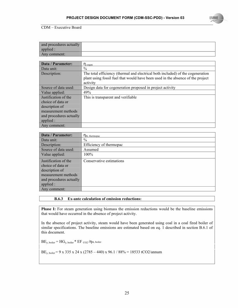
and procedures actually applied : Any comment: Data / Parameter: η cogen Data unit: % Description: The total efficiency (thermal and electrical both included) of the cogeneration
plant using fossil fuel that would have been used in the absence of the project activity
Source of data used: Design data for cogeneration proposed in project activity Value applied: 49% Justification of the choice of data or description of measurement methods and procedures actually applied :
This is transparent and verifiable
Any comment: Data / Parameter: ηth, thermopac Data unit: % Description: Efficiency of thermopac Source of data used: Assumed Value applied: 100% Justification of the choice of data or description of measurement methods and procedures actually applied :
Conservative estimations
Any comment: B.6.3 Ex-ante calculation of emission reductions:
Phase I: For steam generation using biomass the emission reductions would be the baseline emissions that would have occurred in the absence of project activity. In the absence of project activity, steam would have been generated using coal in a coal fired boiler of similar specifications. The baseline emissions are estimated based on eq. 1 described in section B.6.1 of this document. BEy, boiler = HGy, boiler * EF CO2 /ηth, boiler BEy, boiler = 9 x 335 x 24 x (2785 – 440) x 96.1 / 88% = 18533 tCO2/annum

PROJECT DESIGN DOCUMENT FORM (CDM-SSC-PDD) - Version 03 CDM – Executive Board
26
Also, thermopac runs on biomass that would have been based on fuel oil combustion in the absence of project activity. BEy, theropac = HGy, thermopac * EF CO2 /ηth, thermopac BEy, thermopac = 2000 x 4.187 x 335 x 24 x 77.4 / 100%/1000/1000 = 5211 tCO2/annum * Conservative estimates Phase 2: For steam extracted and power generation in the cogeneration unit the emission reductions would be the baseline emissions that would have occurred in the absence of project activity. In the absence of project activity, steam and power would have been generated using coal in coal fired cogeneration unit of similar specifications. The baseline emissions are estimated based on eq. 2 described in section B.6.1 of this document. BEy, cogen = (HGy, cogen + EGy, cogen*3.6) * EF CO2 /ηcogen BEy = [{9.3 x 335 x 24 x (2946-440)/10^6} + {21.708 x 3.6}] x 96.1/ 48% = 51824 tCO2/annum
B.6.4 Summary of the ex-ante estimation of emission reductions:
Year Estimation of project activity emissions (tCO2 e)
Estimations of baseline emissions (tCO2 e)
Estimation of leakage (tCO2 e)
Estimation of overall emission reductions (tCO2 e)
2007* 0 1979 0 1979 2008 0 23744 0 23744 2009 0 57035 0 57035 2010 0 57035 0 57035 2011 0 57035 0 57035 2012 0 57035 0 57035 2013 0 57035 0 57035 2014 0 57035 0 57035 2015 0 57035 0 57035 2016 0 57035 0 57035 2017# 0 52282 0 52282 Total (tonnes of CO2 e)
0 534286 0 534286
*For the period Dec #For the period Jan-Nov B.7 Application of a monitoring methodology and description of the monitoring plan:

PROJECT DESIGN DOCUMENT FORM (CDM-SSC-PDD) - Version 03 CDM – Executive Board
27
B.7.1 Data and parameters monitored: Data / Parameter: EGy, cogen Data unit: GWh Description: The amount of electricity supplied by the project activity during the year y Source of data to be used:
Onsite measurement
Value of data 21.708 Description of measurement methods and procedures to be applied:
Directly measured using energy meter
QA/QC procedures to be applied:
Energy meter is calibrated and checked annually
Any comment: Frequency of monitoring : Daily
Data / Parameter: Qexsteam, II Data unit: tonne Description: Quantity of steam extracted from the turbine in cogeneration unit Source of data to be used:
Onsite measurement
Value of data Actual values taken as part of monitoring procedure Description of measurement methods and procedures to be applied:
Directly Measured using steam flow meter
QA/QC procedures to be applied:
Steam flow meter is calibrated and checked annually
Any comment: Frequency of monitoring : Daily
Data / Parameter: Eexsteam, II Data unit: kcal/kg Description: Enthalpy of steam extracted from cogeneration unit Source of data to be used:
Estimated based on steam pressure and temperature
Value of data - Description of measurement methods and procedures to be applied:
Estimated values
QA/QC procedures to be applied:
Any comment: Frequency of monitoring : Daily
Data / Parameter: EFW, II Data unit: kcal/kg

PROJECT DESIGN DOCUMENT FORM (CDM-SSC-PDD) - Version 03 CDM – Executive Board
28
Description: Enthalpy of feed water into cogeneration unit Source of data to be used:
Estimated based on feed water temperature
Value of data - Description of measurement methods and procedures to be applied:
Estimated values
QA/QC procedures to be applied:
Any comment: Frequency of monitoring : Daily
Data / Parameter: Qsteam, I Data unit: tonne Description: Quantity of steam generated in stand alone boiler Source of data to be used:
Onsite measurement
Value of data Actual values taken as part of monitoring procedure Description of measurement methods and procedures to be applied:
Directly Measured using steam flow meter
QA/QC procedures to be applied:
Steam flow meter is calibrated and checked annually
Any comment: Frequency of monitoring : Daily
Data / Parameter: Esteam, I Data unit: kcal/kg Description: Enthalpy of steam generated in stand alone boiler Source of data to be used:
Estimated based on steam pressure and temperature
Value of data - Description of measurement methods and procedures to be applied:
Estimated values
QA/QC procedures to be applied:
Any comment: Frequency of monitoring : Daily
Data / Parameter: EFW, I Data unit: kcal/kg Description: Enthalpy of feed water into stand alone boiler Source of data to be used:
Estimated based on feed water temperature
Value of data - Description of Estimated values

PROJECT DESIGN DOCUMENT FORM (CDM-SSC-PDD) - Version 03 CDM – Executive Board
29
measurement methods and procedures to be applied: QA/QC procedures to be applied:
Any comment: Frequency of monitoring : Daily
Data / Parameter: QTP Data unit: kcal Description: Quantity of thermic fluid heated in thermopac Source of data to be used:
Onsite measurement
Value of data - Description of measurement methods and procedures to be applied:
Directly measured using flow meter
QA/QC procedures to be applied:
Any comment: Frequency of monitoring : Daily
Data / Parameter: Ti Data unit: Deg C Description: Temperature at inlet of thermic fluid Source of data to be used:
Onsite measurement
Value of data - Description of measurement methods and procedures to be applied:
Directly measured using temperature gauge
QA/QC procedures to be applied:
Any comment: Frequency of monitoring : Daily
Data / Parameter: To Data unit: Deg C Description: Temperature at outlet of thermic fluid Source of data to be used:
Onsite measurement
Value of data - Description of measurement methods and procedures to be applied:
Directly measured using temperature gauge
QA/QC procedures to be applied:

PROJECT DESIGN DOCUMENT FORM (CDM-SSC-PDD) - Version 03 CDM – Executive Board
30
Any comment: Frequency of monitoring : Daily
Data / Parameter: Sp Data unit: Deg C Description: Specific heat of thermic fluid Source of data to be used:
Onsite measurement
Value of data - Description of measurement methods and procedures to be applied:
Thermic fluid tests conducted onsite/ external labs
QA/QC procedures to be applied:
Any comment: Frequency of monitoring : Yearly
Data / Parameter: Biomass availability Data unit: tonnes Description: Surplus biomass availability in the region Source of data to be used:
To be based on publicly available reports on biomass availability in the region from state or central Government agencies and/ or other institutions of repute. GEPL would carry out its own assessment through external experts/ in-house resources in case of non-availability of such information otherwise.
Value of data - Description of measurement methods and procedures to be applied:
-
QA/QC procedures to be applied:
Any comment: Frequency of monitoring : Yearly B.7.2 Description of the monitoring plan:
GEPL has procedures for monitoring and recording of data on operation & maintenance of the plant equipments. Along with data as mentioned in section B.7.2, GEPL would also monitor annually the availability of surplus biomass in the region. This would be done either based on publicly available reports on biomass availability in the region from state or central Government agencies and/ or other institutions of repute. GEPL would carry out its own assessment through external experts/ in-house resources in case of non-availability of such information otherwise. GEPL proposed following structure for data monitoring, collection, data archiving, and calibration of metering equipments. It comprises of the following members:
PROJECT DESIGN DOCUMENT FORM (CDM-SSC-PDD) - Version 03 CDM – Executive Board
31
• Unit head • Power Plant In-charge • Shift In-charge/ shift operator
The unit head is responsible for the overall functioning and maintenance of the project activity. The Power Plant In-charge maintains all the data records and ensures the completeness and reliability of the data. The Shift In-charge maintains a day to day power generation log. The monitoring reports are checked periodically by the Power Plant In-charge and discussed thoroughly with the data monitoring personnel. Corrective action is taken immediately if any improper functioning or operation problem with the equipments is observed. The archived data shall be kept for two years after the crediting period or issuance of CERs. A log will also be maintained for the biomass supply on the site, its storage and usage in the project activity. The project activity does not result in any unidentified activity that can result in substantial emissions from the project activity. Hence, a need for emergency preparedness in the data monitoring is not required. After verification of the data and due diligence on the corrective ness if required, an annual report on monitoring and estimations shall be maintained by the CDM team and record to this effect shall be maintained for verification. B.8 Date of completion of the application of the baseline and monitoring methodology and the name of the responsible person(s)/entity(ies) The baseline and monitoring methodology was completed on 10/06/2007 Mr S K Agarwal General Manager - Projects Gupta Exim Pvt Ltd 144, DLF Industrial Area Phase I, Faridabad - 121-003 Haryana India Phone: 91-129-4090400 Fax: 91-129-2273733 Mobile: 9899884150 Email: [email protected] SECTION C. Duration of the project activity / crediting period C.1 Duration of the project activity: C.1.1. Starting date of the project activity: 20/12/2005 C.1.2. Expected operational lifetime of the project activity: 20 years

PROJECT DESIGN DOCUMENT FORM (CDM-SSC-PDD) - Version 03 CDM – Executive Board
32
C.2 Choice of the crediting period and related information: Fixed crediting period C.2.1. Renewable crediting period C.2.1.1. Starting date of the first crediting period: NA C.2.1.2. Length of the first crediting period: C.2.2. Fixed crediting period: 10 years C.2.2.1. Starting date: 01/12/2007 C.2.2.2. Length: SECTION D. Environmental impacts D.1. If required by the host Party, documentation on the analysis of the environmental impacts of the project activity: The project activity does not require environment impact study to be undertaken as per regulations for pollution control in India. The project activity envisages the use of biomass residue as fuel in steam and power generation and displacement of fossil fuels. There is no adverse impact by the project activity on the environment (air, water, soil). It has only positive impacts in the form of emission reduction of GHG. D.2. If environmental impacts are considered significant by the project participants or the host Party, please provide conclusions and all references to support documentation of an environmental impact assessment undertaken in accordance with the procedures as required by the host Party: GEPL has fulfilled the requirements stipulated under state and central laws for establishment of cogeneration plant. GEPL has received approval from state pollution control board for setting up the plant and also received consent to operate for the boiler. Consents for the proposed cogeneration unit would be obtained once it is commissioned. SECTION E. Stakeholders’ comments

PROJECT DESIGN DOCUMENT FORM (CDM-SSC-PDD) - Version 03 CDM – Executive Board
33
E.1. Brief description how comments by local stakeholders have been invited and compiled: The stakeholder consultation was carried out at various levels and through different modes of consultation. For the project activity, following stakeholders were identified:
District Authorities Village Panchayat Local Community State Electricity Board
A letter was sent to all the stakeholders and various authorities inviting them to the meeting to be conducted by GEPL. An advertisement was also published in the local newspaper, Punjab Kesari. In the meeting conducted, by Mr S.K. Agarwal of GEPL, on 30th June 2007 the project activity undertaken by the company was explained to those present in the meeting. He told the gathering about the greenhouse gases, their impact on the environment and the efforts which will be undertaken by the company to reduce the emission of such gases. It was further explained that all legal and statutory requirements were completed prior to the project activity. The entire procedure of procurement of biomass to reduction in the gases in the surrounding areas was satisfactorily described to the people. The queries put by the people were answered to their contentment by the GEPL representatives. E.2. Summary of the comments received: The efforts put in by GEPL were well accepted by the stakeholders. The village authority appreciated the move by the company in a positive manner. No adverse comments were received by those present in the meeting. E.3. Report on how due account was taken of any comments received: As there are no adverse comments, no specific action was taken.

PROJECT DESIGN DOCUMENT FORM (CDM-SSC-PDD) - Version 03 CDM – Executive Board
34
Annex 1
CONTACT INFORMATION ON PARTICIPANTS IN THE PROJECT ACTIVITY Organization: Gupta Exim Private Limited Street/P.O.Box: 144, DLF Industrial Area, Phase I Building: City: Faridabad State/Region: Haryana Postfix/ZIP: 121-003 Country: India Telephone: 91-129-4090400 FAX: 91-129-2273733 E-Mail: [email protected] URL: Represented by: Title: General Manager (Projects) Salutation: Mr Last Name: Agarwal Middle Name: K. First Name: S. Department: Mobile: 9899884150 Direct FAX: 91-129-2273733 Direct tel: 91-129-4090400 Personal E-Mail: [email protected]

PROJECT DESIGN DOCUMENT FORM (CDM-SSC-PDD) - Version 03 CDM – Executive Board
35
Annex 2
INFORMATION REGARDING PUBLIC FUNDING
No public funding or direct funding from Annex-1 countries availed for this project activity.

PROJECT DESIGN DOCUMENT FORM (CDM-SSC-PDD) - Version 03 CDM – Executive Board
36
Annex 3
BASELINE INFORMATION
Please refer section B.4 for details of baseline estimation.

PROJECT DESIGN DOCUMENT FORM (CDM-SSC-PDD) - Version 03 CDM – Executive Board
37
Annex 4
MONITORING INFORMATION
Please refer section B.7.1 for details of monitoring plan - - - - -