build your own high power rail launch pad your own high power rail launch pad joint against...
TRANSCRIPT

I S S U E 2 3 5 M AY 1 9 , 2 0 0 9
Apogee Components, Inc. — Your Source For Rocket Supplies That Will Take You To The “Peak-of-Flight”3355 Fillmore Ridge Heights
Colorado Springs, Colorado 80907-9024 USAwww.ApogeeRockets.com e-mail: [email protected]
Build Your Own High Power Rail Launch Pad
www.ApogeeRockets.com/Blue_Phenix.asp
Cover Photo: Always Ready Rocketry’s Blue Phenix Kit. For more info, visit:
Can You Believe It Is Well Under $50?
EMRR Corner
Where Does Deceleration Begin?
Tim’s Push-Me-Pull-You Rocket Plan

Page 2 I S S U E 2 3 5 M AY 1 9 , 2 0 0 9
You can subscribe to receive this e-zine FREE at the Apogee Components web site (www.ApogeeRockets.com), or by sending an e-mail to: [email protected] with “SUB-SCRIBE” as the subject line of the message.
About this Newsletter Newsletter Staff
Writer: Tim Van MilliganLayout / Cover Artist: Tim Van MilliganProofreader: Michelle Mason
By Daniel Kirk
Continued on page 3
{Edtor’s Note: In the last newsletter, I disclosed a secret list of ten types of products that I thought would be great selling items (see www.ApogeeRockets.com/Educa-tion/Downloads/Newsletter234.pdf). One of those items on the list was a rail launcher for mid and high power rockets. In response to that article, Daniel Kirk of Union Grove, Wis-consin wrote me about his really cool rail launcher that he built for a really cheap price using PVC pipe he bought at the hardware store. Excluding the rail, the total cost of the launch pad was under ten dollars!}
Parts ListA) 1-1/4” PVC pipe 5 pieces, 3 ft ea. (I’d have to check
the price on this again.)B) 1-1/4” PVC Tees, Slip-fit 3 @ .99 ea.C) 4” electrical junction box cover, 1 @ .55 eaD) Rail Buttons 6 @ .25 ea.E) 1 Wood screwF) 4 small machine screwsG) 7” of scrap 2 x 4 (dimension not critical)H) Rail (http://www.8020.net/): $22 plus shipping
Leg ConstructionCut PVC to length with a hand saw.
Base Construction1. Cut two pieces from the scrap PVC just long enough
to join the tees.2. Join two tees
end-to-end with PVC cement, rotating them so the middle leg of each tee is at a right angle to the other. When dry, add the third tee with its middle leg at 90 degrees to that of the center tee, and 180 degrees to that of the tee at the opposite end.
3. When dry, drill a hole for a machine screw on either side of each joint. Insert screws to strengthen the
Build Your Own High Power Rail Launch Padjoint against rotational forces.
Mast Construction1. Mark a longitudinal line on one length of PVC. (A
Sharpie marker is good for this.) Drill pilot holes on the line, and screw in rail buttons. One at each end would probably do, but I used 4 buttons, one an inch from each end, and another 3 inches from each end. Leave the bottom plastic washer off the rail button for a tighter fit.
Bracket for Blast Deflector Construction1.Cut one end of the 2 x 4 scrap at a 45 degree angle.
Install two rail buttons on the long side, one near the top, and the other 3-4” below it, again omit-ting the bottom washer. Drill a pilot hole, and screw the wood screw into the angled surface near the top.
Figure 2: Base of the launcher. (A) Screws in addition to the glue to provide extra support to keep the mast pole from rotating. (B) Mast pole. (C) Rail buttons to hold rail to the mast pole.
Figure 3: Blast deflector bracket with rail buttons.
Page 3I S S U E 2 3 5 M AY 1 9 , 2 0 0 9
Build A Rail Launch PadContinued from page 2
Continued on page 4
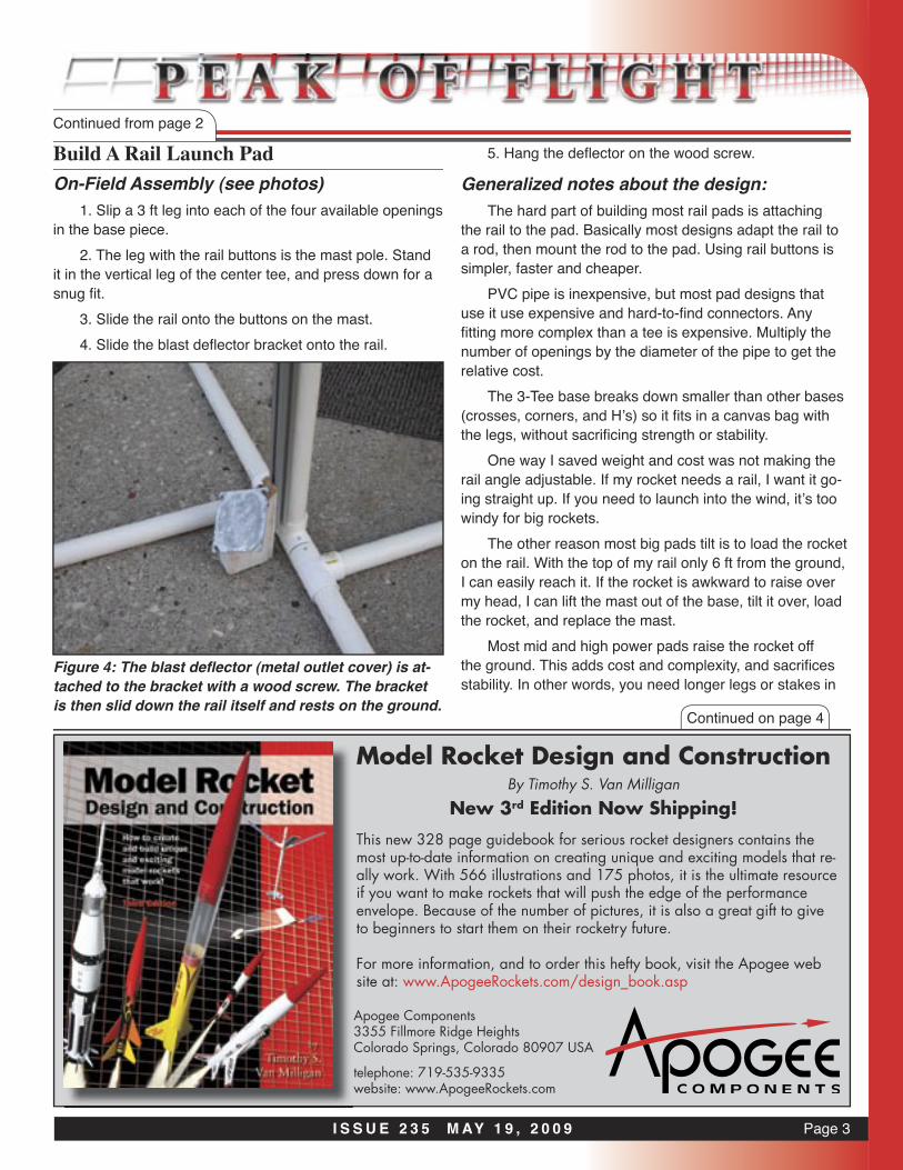
On-Field Assembly (see photos)1. Slip a 3 ft leg into each of the four available openings
in the base piece.2. The leg with the rail buttons is the mast pole. Stand
it in the vertical leg of the center tee, and press down for a snug fi t.
3. Slide the rail onto the buttons on the mast.4. Slide the blast defl ector bracket onto the rail.
5. Hang the defl ector on the wood screw.
Generalized notes about the design:The hard part of building most rail pads is attaching
the rail to the pad. Basically most designs adapt the rail to a rod, then mount the rod to the pad. Using rail buttons is simpler, faster and cheaper.
PVC pipe is inexpensive, but most pad designs that use it use expensive and hard-to-fi nd connectors. Any fi tting more complex than a tee is expensive. Multiply the number of openings by the diameter of the pipe to get the relative cost.
The 3-Tee base breaks down smaller than other bases (crosses, corners, and H’s) so it fi ts in a canvas bag with the legs, without sacrifi cing strength or stability.
One way I saved weight and cost was not making the rail angle adjustable. If my rocket needs a rail, I want it go-ing straight up. If you need to launch into the wind, it’s too windy for big rockets.
The other reason most big pads tilt is to load the rocket on the rail. With the top of my rail only 6 ft from the ground, I can easily reach it. If the rocket is awkward to raise over my head, I can lift the mast out of the base, tilt it over, load the rocket, and replace the mast.
Most mid and high power pads raise the rocket off the ground. This adds cost and complexity, and sacrifi ces stability. In other words, you need longer legs or stakes in
Model Rocket Design and ConstructionBy Timothy S. Van Milligan
New 3rd Edition Now Shipping!
Apogee Components3355 Fillmore Ridge HeightsColorado Springs, Colorado 80907 USA
telephone: 719-535-9335website: www.ApogeeRockets.com
This new 328 page guidebook for serious rocket designers contains the most up-to-date information on creating unique and exciting models that re-ally work. With 566 illustrations and 175 photos, it is the ultimate resource if you want to make rockets that will push the edge of the performance envelope. Because of the number of pictures, it is also a great gift to give to beginners to start them on their rocketry future.
For more information, and to order this hefty book, visit the Apogee web site at: www.ApogeeRockets.com/design_book.asp
Figure 4: The blast defl ector (metal outlet cover) is at-tached to the bracket with a wood screw. The bracket is then slid down the rail itself and rests on the ground.

Page 4 I S S U E 2 3 5 M AY 1 9 , 2 0 0 9
Build A Rail Launch PadContinued from page 3
the ground to keep your pad from tipping over in a gust of wind. It also makes it harder to load the rocket on the pad. The main advantage of raising the pad is that you don’t
Brought to you by Essence’s Model Rocketry Reviews & Resourses - www.rocketreviews.com
Let’s Cluster Some MotorsClustering: A boost technique which uses 2 or more motors side by side in the same rocket. Safe operation of rockets with different motor thrusts, in a cluster would be to ensure symetrical thrust around the center vertical axis of the rocket. This is also sometimes accomplished by canting motors toward the center of gravity.This is also sometimes accomplished by canting motors toward the center of gravity.
Cluster Ignition Tip - check the continuity of each igniter AFTER plug installation but BEFORE you twist them all together.
Fliskits has a very popular and unique way to get into clusters with the exciting Deuce’s Wild Kit.
There may be copies of the idea and design out there, but the Deuce is here to stay!
Boris Katan and his CLUS-TER TOGinator.
What started as a 1.6x upscale of the FlisKits US TOG... turned into some-thing more! Flies on 3x “G” Redline, 12x “E9” and 12x “D11” motors
Figure 5-7: The pad breaks down into components, and is easly transported in a folding chair bag (left). The pad when fully assembled (above) .
Continued on page 5

Page 5I S S U E 2 3 5 M AY 1 9 , 2 0 0 9
Build A Rail Launch PadContinued from page 4
Dollar for dollar, you’ll see the most results by advertising in the Peak-of-Flight Newsletter. In fact, I guarantee it. If you don’t see more results from your advertisement in the Peak-of-Flight Newsletter, I’ll run your
advertisment for two more issues at NO COST!
Call us at: (719) 535-9335
High Power Tubes & Couplers ww
w.A
pogeeRock
ets.co
m
• Won’t Shatter Like Brittle Phenolic Tubes!• Super Smooth Surface With Tight Spirals• Standard LOC Diameters Up To 6 inches
• Cut and Slot With Standard Tools• No Fiberglass Wrap Needed
• Sands and Paints Easily• Cheaper than Fiber-
glass
www.ApogeeRockets.com/blue_tubes.asp
Blue Tube FromAlways ReadyRocketry
have to kneel on ground that may be rocky or wet. Solution: I bought a foam kneeling pad made for gardeners. The de-luxe model is $4.50 at Wal-Mart. If the ground is really wet, I lay a plastic garbage bag on the ground under it.
I fly mostly mid-power. My HPR are toward the smaller end of the scale. For larger rockets, the design could be scaled up with larger diameter pipe, longer legs, longer rail, etc. In that case, I’d add screws as added insurance that the mast and legs couldn’t wiggle.
About the Author:Daniel Kirk writes: “I flew rockets as a kid in the early
‘80s. Even saved enough money from collecting cans and doing odd jobs to go to Space Camp. In 1999, I met Bob Wingate, who introduced me to his club, KCAR #505. I was amazed at the developments since I’d left the hobby in the mid-80’s, and found it was even more fun to fly with a group. I flew with KCAR and also with SMART #644 until I moved to Wisconsin, where I fly with WOOSH #558. I served as president of KCAR for 2 years.
I enjoy designing, building, and flying rockets, and am always looking for new ideas and ways to improve my skills, so I especially enjoy the wealth of information avail-able from Apogee Components.”

Page 6 I S S U E 2 3 5 M AY 1 9 , 2 0 0 9
Staging Electronics• Designed to ignite the top motor in two-stage rockets.
• Provides an easy way to stage composite propel-
lant motors
ww
w.A
pogeeRock
ets.co
m
• Fires off igniters after a preprogrammed amount of
time following liftoff• G-switch senses liftoff and
insures against a false launch-detection
• Small, lightweight design is great for skinny rockets
• Easy-to-use, and will fire off any ig-niter, including clusters!
www.ApogeeRockets.com/Staging_Timer.aspBattery, battery connector, mounting board and igniter are not incuded.
Continued on page 7
By Tim Van Milligan
Where Does Deceleration Start?
Figure 1: Aerotech’s Electronic Forward Closure
I got a question this past week from a RockSim user. The situation was that he was using Aerotech’s Electronic Forward Closure in his rocket, and wanted to know how to set it up in RockSim. That is what I’ll try to explain in this short article.
First of all, we don’t currently carry the Aerotech Elec-tronic Forward Closure, but we can special order it for you if you want it. Just give us a call at (719) 535-9335.
The device is an electronic timer that attaches to the forward end of the Rouse-Tech motor cases (www.apo-geerockets.com/Rouse-Tech_Monster_Motors.asp). It simply replaces the regular forward closure piece on the motor. The purpose of the device is to eject the parachute out of the rocket. Why use it? Many of the bigger motors do not have built-in ejection charges because the case is plugged. And many rocketeers like to get rid of the built-in pyrotechnic delay because they may not be very accurate if improperly assembled. So going to an electronic device can be more accurate. Finally, it can be used for extra redun-dancy in the situation where you are using other electronic devices to control the ejection of the chute.
How does the Electronic Forward Closure differ from other timers, such as the Perfect Flight MiniTimer3 (www.
apogeerockets.com/Staging_Timer.asp)? After all, a timer is a timer; they just count the number of seconds and then fire off an igniter to start an event (an “event” is either igniting another stage in the rocket, or firing off the ejection charge to deploy a parachute).
The obvious physical difference is that the Electronic Forward Closure attaches to the rocket motor, where the MiniTimer3 must be mounted elsewhere in the rocket.
But the key difference is how the devices start. Most electronic timers, such as the MiniTimer3, start by sens-ing lift-off. The MiniTimer has a G-sensor that detects the
Page 7I S S U E 2 3 5 M AY 1 9 , 2 0 0 9
Where Does Deceleration Start?Continued from page 6
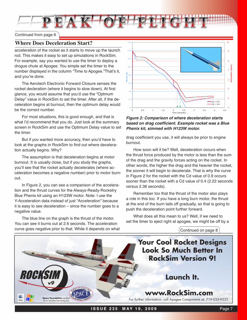
Figure 2: Comparison of where deceleration starts based on drag coefficient. Example rocket was a Blue Phenix kit, simmed with H123W motor.
acceleration of the rocket as it starts to move up the launch rod. This makes it easy to set up simulations in RockSim. For example, say you wanted to use the timer to deploy a drogue chute at Apogee. You simple set the timer to the number displayed in the column “Time to Apogee.”That’s it, and you’re done.
The Aerotech Electronic Forward Closure senses the rocket decleration (where it begins to slow down). At first glance, you would assume that you’d use the “Optmum Delay” value in RockSim to set the timer. After all, if the de-celeration begins at burnout, then the optimum delay would be the correct number.
For most situations, this is good enough, and that is what I’d recommend that you do. Just look at the summary screen in RockSim and use the Optimum Delay value to set the timer.
But if you wanted more accuracy, then you’d have to look at the graphs in RockSim to find out where decelera-tion actually begins. Why?
The assumption is that deceleration begins at motor burnout. It is usually close, but if you study the graphs, you’ll see that the rocket actually decelerates (where ac-celeration becomes a negative number) prior to motor burn-out.
In Figure 2, you can see a comparison of the accelera-tion and the thrust curves for the Always-Ready-Rocketry Blue Phenix kit using an H123W motor. Note: I use the Y-Acceleration data instead of just “Acceleration” because it is easy to see deceleration – since the number goes to a negative value.
The blue line on the graph is the thrust of the motor. You can see it burns out at 2.6 seconds. The acceleration curve goes negative prior to that. While it depends on what
drag coefficient you use, it will always be prior to engine burnout.
How soon will it be? Well, deceleration occurs when the thrust force produced by the motor is less than the sum of the drag and the gravity forces acting on the rocket. In other words, the higher the drag and the heavier the rocket, the sooner it will begin to decelerate. That is why the curve in Figure 2 for the rocket with the Cd value of 0.9 occurs sooner than the rocket with a Cd value of 0.4 (2.22 seconds versus 2.36 seconds).
Remember too that the thrust of the motor also plays a role in this too. If you have a long burn motor, the thrust at the end of the burn tails off gradually, so that is going to push the deceleration point further forward.
What does all this mean to us? Well, if we need to set the timer to eject right at apogee, we might be off by a
Space Foundation certified as an excellent teaching aid. For further information, call Apogee Components at: 719-535-9335.
www.RockSim.comv9
Your Cool Rocket Designs Look So Much Better In
RockSim Version 9!
Launch It.
Continued on page 8

Page 8 I S S U E 2 3 5 M AY 1 9 , 2 0 0 9
significant amount of time. In this example, if you read off the graph that decleration begins at 2.22 seconds when the motor burnout is 2.6 seconds, your timer would be off by .38 seconds if you used the Optimal Delay from the sum-mary screen in RockSim.
Now 0.38 seconds really isn’t a long time in most rock-ets. But you get the idea. You’ll need to check your simula-tions to see if that is going to result in a situation where the rocket is still travelling at a high rate of speed when the drouge chute is ejected.
So the procedure to set the correct delay value for Aerotech’s Electronic Forward Closure is to look at the accleration curve graph and find out when it begins decel-eration. Take that number and subtract it from the total burn time of the motor. This will give you how much time before burnout the rocket decelerates (and where the timer will start timing). Now take this number and add it to the Opti-mal Delay values. The final value is the number you’d use to set the Electronic Forward Closure timer to eject right at apogee.
It isn’t hard, is it?This is a great exercise to learn a bit more about thrust,
drag and gravity. It is fun to play with and see what the rocket may do in a lot of situations as everything changes when your rocket doesn’t go perfectly straight up. RockSim
Where Does Deceleration Start?Continued from page 7
is very valuable in this situation, as it can save you from setting up your electronics incorrectly. That’s one reason why I use it. Do you?
About The Author:Tim Van Milligan (a.k.a. “Mr. Rocket”) is a real rocket
scientist who likes helping out other rocketeers. Before he started writing articles and books about rocketry, he worked on the Delta II rocket that launched satellites into orbit. He has a B.S. in Aeronautical Engineering from Embry-Riddle Aeronautical University in Daytona Beach, Florida, and has worked toward a M.S. in Space Technology from the Florida Institute of Technology in Melbourne, Florida. Cur-rently, he is the owner of Apogee Components (http://www.apogeerockets.com) and the curator of the rocketry educa-tion web site: http://www.apogeerockets.com/education/. He is also the author of the books: “Model Rocket Design and Construction,” “69 Simple Science Fair Projects with Model Rockets: Aeronautics” and publisher of a FREE e-zine newsletter about model rockets. You can subscribe to the e-zine at the Apogee Components web site or by send-ing an e-mail to: [email protected] with “SUB-SCRIBE” as the subject line of the message.
You get:(4) AT 29/13(4) AT 41/18(2) AT 56/18(2) AT 66/18(1) AC-56(1) AC-66Price: $22.72You Save: $5.17
You get:(6) AT 13/18(6) AT 18/18(6) AT 24/18(6) AT 33/18
Price: $26.00From Estes, you would spend over $44.45!
http://www.ApogeeRockets.com/body_tubes.asp
FREE RocketConstruction
VideosA new Apogee video every two weeks to help you become a better modeler!
www.ApogeeRockets.com/Rocketry_Video_tips.asp
Yes...We Have Engine
Mounts Too.www.apogeerockets.com/motor_mount_kits.asp
Page 9I S S U E 2 3 5 M AY 1 9 , 2 0 0 9
By Tim Van Milligan
Rocket Plan: Tim’s Push-Me Pull-You
On page 260 of Model Rocket Design and Construc-tion, I showed a picture of a model I built for the NAR’s competition event called “Four A-motors, Cluster Altitude.” As you might expect, the purpose of the event is to fly the highest possible using four A motors. I never flew the rocket, but I have seen similar designs used in competition, and they worked fine.
A reader of this newsletter, Tsolo Tsolo, asked me if it was possible to simulate this design in RockSim. That got me scratching my head, because I wasn’t sure if it was pos-sible. I knew it wouldn’t be possible in the old version 8, but I told Tsolo that I suspected that it would be in version 9.0.
Well, I had to make sure because my integrity was on the line. Having a few minutes of free time this morning, I sat down and put it into RockSim version 9. It does work!
The design is pretty complicated in version 9, as it has a total of seven external pods, four nose cones, and each of the four fins must be attached seperately. I input the parts the same way that I would have physically built it. But every time I added a part, I first had to add a pod. And even though I used cut-and-paste extensively throughout the process, I still had to revisit every part to make sure that it was positioned and oriented properly. Continued on page 10
High-Power Reload Casings ww
w.A
pogeeRock
ets.co
m
• Reusable Rocket Motors Save Money• Holds Aerotech’s Reload Propellant• Sizes: 24mm To 98mm Diameter• Power Range: E Through N• Cases For Any Project• Rouse-Tech Quality• Affordable!
www.ApogeeRockets.com/Rouse-Tech_Monster_Motors.asp
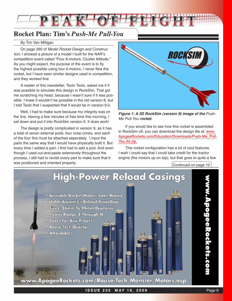
Figure 1: A 3D RockSim (version 9) image of the Push-Me Pull-You rocket.
If you would like to see how this rocket is assembled in RockSim v9, you can download the design file at: www.ApogeeRockets.com/Education/Downloads/Push-Me_Pull-You.rkt.zip.
This rocket configuration has a lot of cool features. I wish I could say that I could take credit for the tractor engine (the motors up on top), but that goes to quite a few

Page 10 I S S U E 2 3 5 M AY 1 9 , 2 0 0 9
Rocket Plan: Tim’s Push-Me Pull-YouContinued from page 9
Tim's Push-me Pull-YouLength: 22.6550 In. , Diameter: 0.5440 In. , Span diameter: 5.1337 In.Mass 54.277 g , Selected stage mass 54.277 gCG: 13.6153 In., CP: 19.8343 In., Margin: 11.45 OverstableEngines: [A3T-4, A3T-4, A3T-4, A3T-4, ]
(M)(S)(S) (M)
modelers that have done it before my time.By using the tractor motors in the front, the diameter
of the rocket is reduced and therefore the drag is reduced. That allows the rocket to fly higher than an arrangement where all the four motors were clustered at the rear of the model. In addition to that, the tractor motors also shift the CG of the rocket forward making the model more stable.
Plus, the two motors on top control two different streamers for recovery. That gives some redundancy to the rocket in case one motor in the top does not ignite properly.
According to RockSim, this rocket can reach 1,600 feet (487.7m) on four A3-4T motors. It could go higher if there
was a longer available delay. If such an motor actually ex-isted, the rocket could top out at 2028 feet (618.1m). If you did a delayed ignition on the tractor motors, so that they lit a little later in the flight, the rocket can go even higher. Pretty cool, eh?
The one drawback is that the exhaust of the tractor motors are going to impinge on the lower nose cones. Because of that, I’d recommend they be solid balsawood, and coated with epoxy to give them some heat resistence. It is going to get pretty sooty between flights, but the effect is going to be pretty cool when you launch it.
Don’t you think that RockSim v9 is very cool to allow such a configuration? Imagine what creative things you could design using it...
Available Online &Worldwide throughQuality Hobby Shops& Online Retailers
NOW ON SALE - 25% off selected model rocket kits - available from Apogee Rockets and Sunward!
TM
NOW ON SALE - 25% off Nylon Parachutes, NOMEX® Flame Resistant Blankets and Shock Cord Protectorsavailable from Sunward - www.sunward1.com
NEW 24” x 24” NOMEX® Flame Resistant Blankets and 5 foot x foot NOMEX® Flame Resistant Ground Cover Blankets
www.sunward1.com [email protected] 416-953-1847 fax 416-245-7985
SALE EXTENDED UNTIL MAY 31. GREAT SAVINGS NOWTM TM