bs66f3x0 and bs67f3x0 enhanced touch flash mcu application ... · bs66f3x0 and bs67f3x0 enhanced...
TRANSCRIPT

BS66F3x0 and BS67F3x0 Enhanced Touch Flash MCU Application Guidelines
AN0431E V1.00 1 / 20 December 11, 2016
BS66F3x0 and BS67F3x0 Enhanced Touch Flash MCU Application Guidelines
D/N:AN0431E
Introduction Holtek’s Enhanced Touch A/D Flash MCUs, the BS66F340/350/360/370, and Enhanced
Touch A/D LCD Flash MCUs, the BS67F340/350/360/370, integrate the enhanced Touch
Key Engine V3.2 version, which with its hardware acceleration circuitry, offers superior
Touch Key algorithm efficiency. These devices also provide highly integrated SoC solutions,
which can allow both master control MCU and touch key functions to be implemented in the
same MCU. Some of the special characteristics of the devices can be seen in their
industrial quality specification of -40°C~85°C, operating voltage range of 2.2V~5.5V, Flash
Program Memory capacity of 4K/8K/16K/32K words, SRAM Data Memory capacity of
512/768/1024/1536 bytes, touch keys pin-shared with I/O ports, I²C, SPI and UART
interfaces, fully integrated high accuracy RC oscillator, four selectable Low Voltage Reset
voltages and eight selectable Low Voltage Detector voltages. Containing 16, 20, 28 or 36
touch keys and in addition to the advantages of the previous generation devices, these new
devices have an enhanced touch detection rate and improved anti-interference abilities.
The BS66F3x0 internal LED drivers support four segments with current output control
which can drive LED displays directly without requiring additional external current-limiting
resistors or transistors. With fewer components and lower costs, the devices will find
excellent use in small appliances which require more touch keys and include LED display
as well as multiple functions, such as thermostats, electric cookers, microwave ovens,
consumer electronic products and others.
The BS67F3x0 internal 1/3 Bias R-Type and C-Type LCD drivers, which are able to drive
LCD panel display directly, support 24SEG × 4COM, 32SEG × 4COM, 40SEG × 4COM
and 48SEG × 4COM. With fewer components and lower costs, the devices will find
excellent use in small appliances which require more touch keys and include LCD display
as well as multiple functions, such as thermostats, electric cookers, microwave ovens,
consumer electronic products and others.
The BS66F3x0 and BS67F3x0 devices also include an 8-channel 12-bit A/D converter for
temperature, humidity and other voltage measurements for products such as thermostats,
electric cookers, electric ovens and other products. With their integrated 128×8 EEPROM,
the devices can store application parameters and settings directly. By also including
BS66F3x0 and BS67F3x0 Enhanced Touch Flash MCU Application Guidelines
AN0431E V1.00 2 / 20 December 11, 2016
Holtek's In-Application program technology, users have a convenient means with which to
directly store their measured data in the Flash Program Memory as well as having the ability
to update their application programs. The internal RTC oscillator, with its extremely low
power consumption, makes the devices applicable for use in battery powered products,
when the devices are in the Power Down mode.
As is the case with other Holtek 8-bit MCUs, these new devices have a full array of
protection features including high noise immunity, Watchdog Timer and Low Voltage Reset
to provide maximum protection when operating in electrically hostile environments. During
product development, by also providing an e-Link coupled with an OCDS EV device, as well
as Holtek's new touch development software platform, users have all the tools at hand to
ensure rapid touch switch product development.
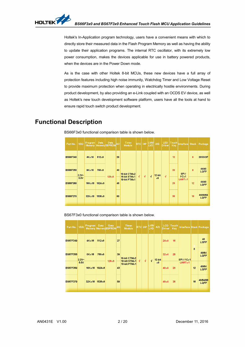
Functional Description BS66F3x0 functional comparison table is shown below.
BS67F3x0 functional comparison table is shown below.

BS66F3x0 and BS67F3x0 Enhanced Touch Flash MCU Application Guidelines
AN0431E V1.00 3 / 20 December 11, 2016
Figure 1
Figure 1 shows the BS66F3x0 and BS67F3x0 block diagram, which illustrates the Holtek
8-bit MCU core integrated with a Touch Key Engine (V3.2) and related peripherals, where
the BS66F3x0 supports LED display driving and the BS67F3x0 supports LCD display
driving.
Figure 2, 3 and 4 show the BS66F3x0 and BS67F3x0 application block diagrams.
Figure 2
Figure 3

BS66F3x0 and BS67F3x0 Enhanced Touch Flash MCU Application Guidelines
AN0431E V1.00 4 / 20 December 11, 2016
A/D
VDD
VSS10µF0.1µF
VDD
Analog Signals
KEY1
KEYx
XT1
XT232768Hz
TM PWM / Capture
TM Buzzer
OSC1
OSC2
System Crystal
I/O Control Device
COM0~COM3SEGx
I/O
RX
RS488 Transceiver
TX
I/ORS_DIR
SPI/I2C Communication Device
BS66F3x0
BS67F3x0
Figure 4
Operating Principles
Enhanced Touch Key Engine V3.2 The BS66F3x0 and BS67F3x0 devices use the enhanced V3.2 Touch Key Engine, which
with its hardware acceleration circuitry, offers significantly enhanced Touch Key algorithm
efficiency, to implement more complex product functions. The main features are as follows:
The hardware reads the reference oscillator settings for all touch keys automatically
The hardware stores the C/F counter values for all touch keys automatically
An interrupt will not be generated until the hardware has scanned all touch keys once
The operating modes are backward compatible to the V3.0 version

BS66F3x0 and BS67F3x0 Enhanced Touch Flash MCU Application Guidelines
AN0431E V1.00 5 / 20 December 11, 2016
The following figure shows the control block diagram and Data Memory Map, where the C/F
counter value is stored in RAM Bank 5, the Ref. OSC setting value is stored in RAM Bank
6, and the TKRAMC (TKC0.7) bit is used to determine if RAM Bank 5/6 can be accessed
and controlled by the Touch Key Engine (TKRAMC=1) or by the MCU (TKRAMC=0).
Single Port RAM
(Bank 5/6)MU
X
MCU
Touch Key Engine(V3.2)
Ref. OSC capacitor
C/F counter
SFR
TKRAMC
0
1
16-bit C/F counter
TKMn16DL / TKMn16DH
10-bit Ref. OSC capacitor
TKMnROL / TKMnROH
Touch Key Engine(V3.2)
TKM016DL_K1
TKM016DH_K1
TKM016DL_K2
TKM016DH_K2
TKM016DL_K3
TKM016DH_K3
TKM016DL_K4
TKM016DH_K4
TKM116DL_K1
TKM116DH_K1
TKM116DL_K2
TKM116DH_K2
TKM116DL_K3
TKM116DH_K3
TKM116DL_K4
TKM116DH_K4
Module 0
TKM0ROL_K1
TKM0ROH_K1
TKM0ROL_K2
TKM0ROH_K2
TKM0ROL_K4
TKM0ROH_K4
TKM0ROL_K3
TKM0ROH_K3
TKM1ROL_K1
TKM1ROH_K1
TKM1ROL_K2
TKM1ROH_K2
TKM1ROL_K4
TKM1ROH_K4
TKM1ROL_K3
TKM1ROH_K3
TKM216DL_K1
TKM216DH_K1
TKM216DL_K2
TKM216DH_K2
TKM216DL_K3
TKM216DH_K3
TKM216DL_K4
TKM216DH_K4
TKM316DL_K1
TKM316DH_K1
TKM316DL_K2
TKM316DH_K2
TKM316DL_K3
TKM316DH_K3
TKM316DL_K4
TKM316DH_K4
TKM2ROL_K1
TKM2ROH_K1
TKM2ROL_K2
TKM2ROH_K2
TKM2ROL_K4
TKM2ROH_K4
TKM2ROL_K3
TKM2ROH_K3
TKM3ROL_K1
TKM3ROH_K1
TKM3ROL_K2
TKM3ROH_K2
TKM3ROL_K4
TKM3ROH_K4
TKM3ROL_K3
TKM3ROH_K3
Module 1
Module 2
Module 3
C/F counter(Bank 5)
Ref. OSC Cap.(Bank 6)
Module n
00H01H02H......
.
.
.
.
.
.

BS66F3x0 and BS67F3x0 Enhanced Touch Flash MCU Application Guidelines
AN0431E V1.00 6 / 20 December 11, 2016
Touch Key Engine V3.0 and V3.2 Functional Comparison Item V3.0 V3.2
Ref. OSC Settings
These settings should be rewritten by the software before each key is scanned.
Before the key scan operations, all key settings should be written to the RAM, and then these settings will be automatically loaded in sequence by the hardware.
C/F counter values
These values should be re-read by the software after each key is scanned.
In the key scan process, the C/F counter results will be automatically written to the RAM in sequence by the hardware, and then read from the RAM by the software.
Touch Key scanning sequence
One key in each module will be scanned. The scanning sequence is switched by the software.
The hardware will automatically scan all the four keys in each module in a specific sequence which can be adjusted flexibly.
Interrupts
After one key in each module has been scanned, an interrupt request flag will be generated. That is, four interrupts for one scan cycle.
After the last key in all modules has been scanned, an interrupt request flag will be generated. That is, one interrupt for one scan cycle.
Touch Key RAM None
The used RAM size is different according to the number of touch keys. When the Touch Key function is not used, the RAM can be used for normal user RAM storage.
The number of registers
Common: 28 bit register Each Module: 41 bit register
Common: 31 bit register Each Module: 47 bit register
Operation modes Firmware (V3.0) control Firmware (V3.0) / Auto control (V3.2)
Touch MCU Development Platform – Touch MCU Workshop In order to help customers rapidly develop their touch products, Holtek provides a Touch
MCU Workshop to assist customers to quickly implement BS66F3x0 and BS67F3x0 touch
switch functions. The main features are as follows:
Customers do not need to develop the underlying touch program code themselves
Easy to use, allowing entry-level developers to get started quickly
The touch key functions can be implemented using drag and drop operations
Based on the program framework generated by the platform, users can modify or
expand their program
Easy to add other MCU functions besides touch key function for fast application
development
Open libraries for which users can add their own MCU functional program
Can be an assistive tool for project management

BS66F3x0 and BS67F3x0 Enhanced Touch Flash MCU Application Guidelines
AN0431E V1.00 7 / 20 December 11, 2016
Touch MCU workshop software interface description:
Setup the required MCU I/O pins as touch switch keys
Setup the touch library parameters
Provides program compiler and programming functions. The program can be
downloaded to the MCU after successful compilation.
Code generator
Based on the program framework generated by the platform, advanced users can
use the HT-IDE3000 to continue with their project development.
Tuning software
Provides a touch key sensitivity adjustment function
Allows users to observe the other touch key conditions immediately after adjusting
one touch key using the platform’s internal oscilloscope display.
Touch MCU Workshop Development Flow:
Touch Software Library The Holtek touch software library no longer just includes basic touch functions, but also
provides peripheral functional modules such as LED drivers, slider functions, wheel
functions, communication functions, voice functions and others.
These functions can be developed by original product engineers or third party agents, and
encapsulated into software packages which can then be provided to developers who
require their functions. By using these software functions, users are then relieved of the task
of repeated software development thus speeding up product development and lowering the
development threshold for touch key applications.
Software Library Structure and Rules: For functional modularity it is required to develop
software libraries for different functions. To ensure a standardised method of software
library development, some rules including file composition and naming rules must be
established.

BS66F3x0 and BS67F3x0 Enhanced Touch Flash MCU Application Guidelines
AN0431E V1.00 8 / 20 December 11, 2016
A software library should have at least four basic files (it also can add other documents or
schematic diagrams) and the four files must have the same base name and different
extension to distinguish their different purposes. The four basic files are:
1. xxxx.ASM: the assembly program file. If using C code, replace “.ASM” with “.C”. If there
is a confidentiality requirement then use the “.OBJ” extension. The touch software library
uses an .OBJ format.
2. xxxx.CEX: the reference file provided by the software library for other software libraries.
(C language)
3. xxxx.AEX: the reference file provided by the software library for other software libraries.
(Assembly language)
4. xxxx.INC: if the parameters, names or functions, which are set in other software libraries,
are used in the program file, the package library’s external reference file (.AEX file
or .CEX file) must be added into the .INC file.
For convenient management of increasing software libraries, it is required to not only have
the above files, but also to locate them in the same folder with their common base name, as
shown below.
Folder Name Files in the Folder
The closer to the actual functional description the folder name is, the better users can
understand the software library function, version or applicability.
Advantages of using a software library:
Helps users get started quickly and avoids repeating the same functional development
tasks
Shorten the product development cycle
Easy program management
Users can generate related library according to their requirements
Each functional module is independent which allows different people at the same time
to implement different module development.
Compatible with both assembly and C language and can be used together with the
Platform.

BS66F3x0 and BS67F3x0 Enhanced Touch Flash MCU Application Guidelines
AN0431E V1.00 9 / 20 December 11, 2016
Used with the Touch Development Platform:
Using the platform allows the direct adjustment of some parameters including
sensitivity, I/O configuration, etc.
Supports superposition of different functional modules
Users can modify the application function themselves then add it to the platform
More efficient program file management
Resource sharing
The BS66F3x0 and BS67F3x0 software library used resources are as follows:
IC ROM RAM Stack Interrupt Other
BS66F340 36% (total 4K)
36% (Total 512 bytes) Bank0 (80H-0AAH) Bank1 (80H-0A3H) Bank2 (80H-0AFH) Bank3 (80H-0BDH)
4 Time base0 Touch Key_Int
MP1L; MP1H; MP2H; MP2L
BS66F350 19% (total 8K)
37% (Total 768 bytes) Bank0 (80H-0B4H) Bank1 (80H-0BBH) Bank2 (80H-0CFH) Bank3 (80H-0DEH)
4 Time base0 Touch Key_Int
MP1L; MP1H; MP2H; MP2L
BS66F360 10% (total 16K)
37% (Total 1024 bytes) Bank0 (80H-0BFH) Bank1 (80H-0D4H) Bank2 (80H-0EFH) Bank3 (80H-0FFH)
4 Time base0 Touch Key_Int
MP1L; MP1H; MP2H; MP2L
BS66F370 5% (total 32K)
31% (Total 1536 bytes) Bank0 (80H-0CAH) Bank1 (80H-0ECH) Bank2 (80H-0FFH) Bank3 (80H-0FFH) Bank4 (80H-0A1H) Bank5 (80H-090H)
4 Time base0 Touch Key_Int
MP1L; MP1H; MP2H; MP2L
BS67F340 37% (total 4K)
46% (Total 512 bytes) Bank0 (80H-0AEH) Bank1 (80H-0AFH) Bank2 (80H-0BFH) Bank3 (80H-0CDH)
4 Time base0 Touch Key_Int
MP1L; MP1H; MP2H; MP2L
BS67F350 19% (total 8K)
37% (Total 768 bytes) Bank0 (80H-0B4H) Bank1 (80H-0BBH) Bank2 (80H-0CFH) Bank3 (80H-0DEH)
4 Time base0 Touch Key_Int
MP1L; MP1H; MP2H; MP2L
BS67F360 10% (total 16K)
37% (Total 1024 bytes) Bank0 (80H-0BFH) Bank1 (80H-0D4H) Bank2 (80H-0EFH) Bank3 (80H-0FFH)
4 Time base0 Touch Key_Int
MP1L; MP1H; MP2H; MP2L
BS67F370 5% (total 32K)
31% (Total 1536 bytes) Bank0 (80H-0CAH) Bank1 (80H-0ECH) Bank2 (80H-0FFH) Bank3 (80H-0FFH) Bank4 (80H-0A1H) Bank5 (80H-090H)
4 Time base0 Touch Key_Int
MP1L; MP1H; MP2H; MP2L

BS66F3x0 and BS67F3x0 Enhanced Touch Flash MCU Application Guidelines
AN0431E V1.00 10 / 20 December 11, 2016
Touch Software Package Usage
Flowchart
Create a new project folder and copy the required software libraries (functional modules) and
KS_GLOBE_VARIESE.INC (.H) into it
Start the IDE3000 and create a new project
Add the program files in the respectivesoftware libraries to the project
Modify or edit the .INC (.H) and TKS_GLOBE_VARIES.INC (.H) files in the
software libraries
Execute the IDE3000 compiler function
Is the compiled result right?
Add or modify application programs in the USER_PROGRAM.ASM (.C)
After the project is completed, execute function test and parameter adjustment
Are other application functions added?
Execute the IDE3000 compiler function
Is the compiled result right?
No
Yes
No
No
Yes
Yes
BS66F3x0 and BS67F3x0 Enhanced Touch Flash MCU Application Guidelines
AN0431E V1.00 11 / 20 December 11, 2016
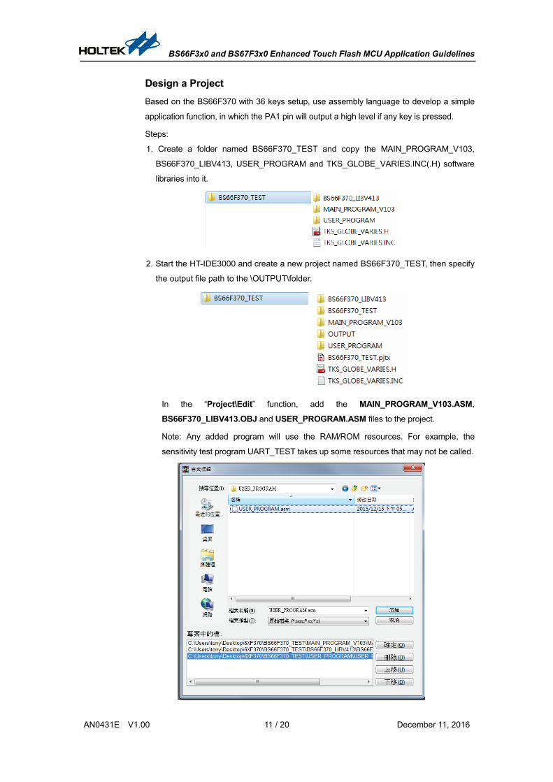
Design a Project Based on the BS66F370 with 36 keys setup, use assembly language to develop a simple
application function, in which the PA1 pin will output a high level if any key is pressed.
Steps:
1. Create a folder named BS66F370_TEST and copy the MAIN_PROGRAM_V103,
BS66F370_LIBV413, USER_PROGRAM and TKS_GLOBE_VARIES.INC(.H) software
libraries into it.
2. Start the HT-IDE3000 and create a new project named BS66F370_TEST, then specify
the output file path to the \OUTPUT\folder.
In the “Project\Edit” function, add the MAIN_PROGRAM_V103.ASM,
BS66F370_LIBV413.OBJ and USER_PROGRAM.ASM files to the project.
Note: Any added program will use the RAM/ROM resources. For example, the
sensitivity test program UART_TEST takes up some resources that may not be called.

BS66F3x0 and BS67F3x0 Enhanced Touch Flash MCU Application Guidelines
AN0431E V1.00 12 / 20 December 11, 2016
3. Modify the MAIN_PROGRAM_V103 \ MAIN_PROGRAM_V103.INC contents. INCLUDE "..\BS66F370_LIBV413\BS66F370_LIBV413.AEX" #DEFINE EXTEND_FUNCTION_1A_INITIAL _BS66F370_LIBV413_INITIAL #DEFINE EXTEND_FUNCTION_1A _BS66F370_LIBV413
INCLUDE "..\USER_PROGRAM\ USER_PROGRAM.AEX" #DEFINE EXTEND_FUNCTION_1B_INITIAL _ USER_PROGRAM _INITIAL #DEFINE EXTEND_FUNCTION_1B _ USER_PROGRAM
Modify the USER_PROGRAM \ USER_PROGRAM.INC contents.
INCLUDE "..\BS66F370_LIBV413\BS66F370_LIBV413.AEX"
The BS66F370_LIBV413 does not refer to the parameters of other software libraries,
therefore, the .INC contents are not required to be modified.
Modify the parameter definitions in TKS_GLOBE_VARIES.INC.

BS66F3x0 and BS67F3x0 Enhanced Touch Flash MCU Application Guidelines
AN0431E V1.00 13 / 20 December 11, 2016
BS66F3x0 and BS67F3x0 Enhanced Touch Flash MCU Application Guidelines
AN0431E V1.00 14 / 20 December 11, 2016
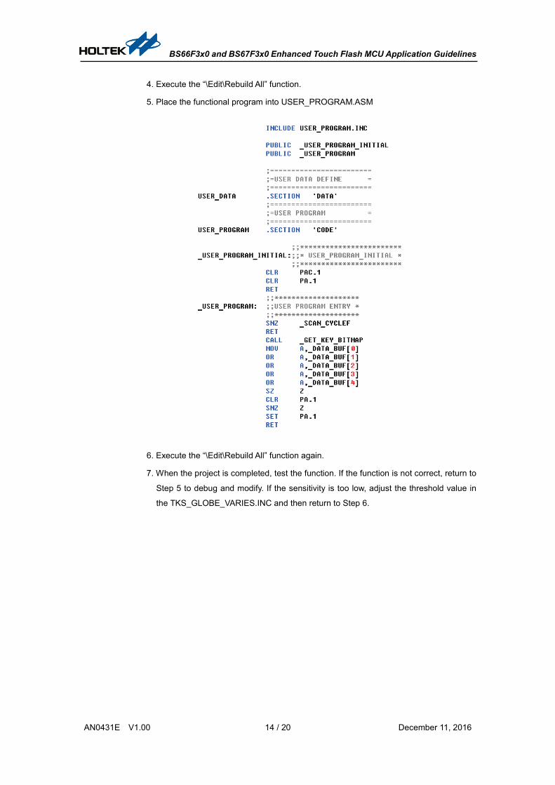
4. Execute the “\Edit\Rebuild All” function.
5. Place the functional program into USER_PROGRAM.ASM
6. Execute the “\Edit\Rebuild All” function again.
7. When the project is completed, test the function. If the function is not correct, return to
Step 5 to debug and modify. If the sensitivity is too low, adjust the threshold value in
the TKS_GLOBE_VARIES.INC and then return to Step 6.

BS66F3x0 and BS67F3x0 Enhanced Touch Flash MCU Application Guidelines
AN0431E V1.00 15 / 20 December 11, 2016
Software Library Usage Considerations
Specify Correct Path
Check if the folder path is correct. In the *.INC or *.H file,
INCLUDE "..\ Software Library Name \ Software Library Name.AEX" includes path
declaration.
Where “..” means to go back to the upper path, and finally point to *.AEX files in the
software library folder.
Program Entry Declaration
In the MAIN_PROGRAM_V103.INC, in addition to the added reference files for other
software libraries, the software library program entries, including the initialisation program
and functional program, should be specified.
INCLUDE "..\BS66F370_LIBV413\BS66F370_LIBV413.AEX" #DEFINE EXTEND_FUNCTION_1A_INITIAL _BS66F370_LIBV413_INITIAL #DEFINE EXTEND_FUNCTION_1A _BS66F370_LIBV413 INCLUDE "..\USER_PROGRAM\ USER_PROGRAM.AEX" #DEFINE EXTEND_FUNCTION_1B_INITIAL _ USER_PROGRAM _INITIAL #DEFINE EXTEND_FUNCTION_1B _ USER_PROGRAM
Program Address Declaration
The Program address, including interrupt address, are declared in an absolute address
method, not using the ORG method.
Data RAM Declaration
The Data RAM is declared using DB and DBIT
Note: For the Program Address and Data RAM declarations, refer to the appendix and the
IDE3000 user’s guide.

BS66F3x0 and BS67F3x0 Enhanced Touch Flash MCU Application Guidelines
AN0431E V1.00 16 / 20 December 11, 2016
Hardware Description
BS66F370 Evaluation Board PCB Schematic Diagram

BS66F3x0 and BS67F3x0 Enhanced Touch Flash MCU Application Guidelines
AN0431E V1.00 17 / 20 December 11, 2016

BS66F3x0 and BS67F3x0 Enhanced Touch Flash MCU Application Guidelines
AN0431E V1.00 18 / 20 December 11, 2016
BS67F370 Evaluation Board PCB Schematic Diagram

BS66F3x0 and BS67F3x0 Enhanced Touch Flash MCU Application Guidelines
AN0431E V1.00 19 / 20 December 11, 2016
Conclusion
This application note content has summarised the BS66F3x0 and BS67F3x0 V3.2 Touch Key
Engine features, providing usage considerations and other information. When combined with
touch library examples, this will assist users to use the various device functions.
Versions and Modify Information
Data Author Issue Release and Modification
2016.07.20 李乾嘉(Holtek) 謝東霖(優方)
First Version
References
Reference file: BS66F3x0, BS67F3x0 Datasheet.
For more information, refer to Holtek’s official website http://www.holtek.com.tw/en/home.
BS66F3x0 and BS67F3x0 Enhanced Touch Flash MCU Application Guidelines
AN0431E V1.00 20 / 20 December 11, 2016
Disclaimer All information, trademarks, logos, graphics, videos, audio clips, links and other items
appearing on this website ('Information') are for reference only and is subject to change at
any time without prior notice and at the discretion of Holtek Semiconductor Inc.
(hereinafter 'Holtek', 'the company', 'us', 'we' or 'our'). Whilst Holtek endeavors to ensure
the accuracy of the Information on this website, no express or implied warranty is given
by Holtek to the accuracy of the Information. Holtek shall bear no responsibility for any
incorrectness or leakage.
Holtek shall not be liable for any damages (including but not limited to computer virus,
system problems or data loss) whatsoever arising in using or in connection with the use of
this website by any party. There may be links in this area, which allow you to visit the
websites of other companies. These websites are not controlled by Holtek. Holtek will
bear no responsibility and no guarantee to whatsoever Information displayed at such sites.
Hyperlinks to other websites are at your own risk.
Limitation of Liability In any case, the Company has no need to take responsibility for any loss or damage
caused when anyone visits the website directly or indirectly and uses the contents,
information or service on the website.
Governing Law This disclaimer is subjected to the laws of the Republic of China and under the jurisdiction
of the Court of the Republic of China.
Update of Disclaimer Holtek reserves the right to update the Disclaimer at any time with or without prior notice,
all changes are effective immediately upon posting to the website.