bellswipe manual (pd-026 iss 3) - bell system uk manual (pd-026 iss 3).pdf · a bellswipe reader...
TRANSCRIPT

bellswipeCard Access System
Bell System (Telephones) Ltd.Presley Way, Crown Hill, Milton Keynes MK8 0ET.
Tel: 01908 261106 FAX: 01908 261116email: [email protected] website: www.bellsystem.co.uk
PD-026 Issue 3

bellswipe Card Access System
System features
� Up to 500 User cards.
� Two Time Zones for Staff / Executive operation.
� Outputs for Fail-safe and Fail-secure locks plus one isolated contact
� Shadow cards for easy deletion of User cards
� Eight function cards for easy system programming.
� Hi-Co Cards for a long durable life: Secure encrypted card data.
� Separate Control unit for maximum security.
� Combined Power Supply and Control Unit for simplified installation.
� Card data is retained after power failure using EEPROM.
� Optional battery backup for operation during mains power failure.
BS500 Kit Components
1 CR500 Control Unit with integral Power Supply
1 RH10 Card Reader
1 203 Lock Release (fail-secure)
1 BSF Starter Pack of cards ( 8 Function cards + 16 user cards & shadow cards)
Optional Components
Part No. Description
BS20C Additional pack of cards for 20 users (includes shadow cards)
TS2000 Time Clock, 7 day, quartz reserve, 12V operated
BAT02 12V 2AH Battery for CR500
bellswipe Card Access System
Contents
General Description . . . . . . . . . . . . . . . . . . . . . . . . . . . . . . . . . . . . . . . . . . . . 1
Basic Operation . . . . . . . . . . . . . . . . . . . . . . . . . . . . . . . . . . . . . . . . . . 1
Time-restricted access (Staff / Executive operation) . . . . . . . . . . . . . . 2
Exit Facility . . . . . . . . . . . . . . . . . . . . . . . . . . . . . . . . . . . . . . . . . . . . . . 2
Integrated Power Supply with optional battery backup . . . . . . . . . . . . 2
Installation . . . . . . . . . . . . . . . . . . . . . . . . . . . . . . . . . . . . . . . . . . . . . . . . . . . . 3
Wiring diagram . . . . . . . . . . . . . . . . . . . . . . . . . . . . . . . . . . . . . . . . . . . 3
Cable Requirements . . . . . . . . . . . . . . . . . . . . . . . . . . . . . . . . . . . . . . . 4
Important Safety Information . . . . . . . . . . . . . . . . . . . . . . . . . . . . . . . . 5
CR500 Control Unit . . . . . . . . . . . . . . . . . . . . . . . . . . . . . . . . . . . . . . . 8
RH10 Card Reader . . . . . . . . . . . . . . . . . . . . . . . . . . . . . . . . . . . . . . . . 9
Electric Lock Release . . . . . . . . . . . . . . . . . . . . . . . . . . . . . . . . . . . . . 11
Isolated Lock Relay Contact . . . . . . . . . . . . . . . . . . . . . . . . . . . . . . . 12
High Current Lock Releases . . . . . . . . . . . . . . . . . . . . . . . . . . . . . . . 13
Time Restricted Access . . . . . . . . . . . . . . . . . . . . . . . . . . . . . . . . . . . 14
Exit Facility . . . . . . . . . . . . . . . . . . . . . . . . . . . . . . . . . . . . . . . . . . . . . 14
Commissioning . . . . . . . . . . . . . . . . . . . . . . . . . . . . . . . . . . . . . . . . . . . . . . . 15
BS500 Kit . . . . . . . . . . . . . . . . . . . . . . . . . . . . . . . . . . . . . . . . 15
Adding further User cards . . . . . . . . . . . . . . . . . . . . . . . . . . . 17

bellswipe Card Access System
System/Card Management . . . . . . . . . . . . . . . . . . . . . . . . . . . . . . . . . . . . . 18
Summary of function cards . . . . . . . . . . . . . . . . . . . . . . . . . . . . . . . . 19
Programming the Lock Release time . . . . . . . . . . . . . . . . . . . . . . . . 20
Enabling or Changing a group of cards . . . . . . . . . . . . . . . . . . . . . . 21
Adding or Changing a card . . . . . . . . . . . . . . . . . . . . . . . . . . . . . . . . 23
Disabling a User Card . . . . . . . . . . . . . . . . . . . . . . . . . . . . . . . . . . . . 25
Deleting all user cards . . . . . . . . . . . . . . . . . . . . . . . . . . . . . . . . . . . 25
The TEST LOCK card . . . . . . . . . . . . . . . . . . . . . . . . . . . . . . . . . . . . 26
Engineering Functions . . . . . . . . . . . . . . . . . . . . . . . . . . . . . . . . . . . . . . . . 27
Restoring Factory Settings . . . . . . . . . . . . . . . . . . . . . . . . . . . . . . . . 27
Enabling the starter Pack . . . . . . . . . . . . . . . . . . . . . . . . . . . . . . . . . 27
Replacing the function cards . . . . . . . . . . . . . . . . . . . . . . . . . . . . . . 29
Troubleshooting . . . . . . . . . . . . . . . . . . . . . . . . . . . . . . . . . . . . . . . . . . . . . . 30
Summary of LED operation . . . . . . . . . . . . . . . . . . . . . . . . . . . . . . . 30
Fault Finding . . . . . . . . . . . . . . . . . . . . . . . . . . . . . . . . . . . . . . . . . . . 31
Testing . . . . . . . . . . . . . . . . . . . . . . . . . . . . . . . . . . . . . . . . . . . . . . . 33
Specification . . . . . . . . . . . . . . . . . . . . . . . . . . . . . . . . . . . . . . . . . . . . . . . . . 36
bellswipe Card Access System
1
General Description
The bellswipe Card Access System is a high quality security product for
controlling access to offices and apartments using proven Magstripe technology.
A Bellswipe reader should be installed adjacent to the building entrance, and the
door fitted with an electric lock release or magnetic lock. Authorised personnel
are each issued with an individual BellSwipe card. Swiping a valid card through
the reader will result in the door being released for a few seconds. A Time-clock
may be used to restrict access to certain card holders to specific times of the day
or week.
Basic Operation
When a valid user card is swiped through the reader the green LED illuminates
and the electric lock release operates for a predetermined time (1-250 seconds).
If an invalid card is swiped the red LED illuminates for 1 second and the lock
release does not operate. A card may be invalid either because it has not been
enabled on the system or its use has been restricted to another time period.
Swiping a Card
Swipe in the direction indicated by the arrows on
the reader and on the card, ensuring the black
Magnetic stripe passes through the reader .

bellswipe Card Access System
2
Time-restricted access (Staff / Executive operation)
Each card may be individually (or as a group) programmed to operate during a
restricted time period only. This time period can be determined by a time-clock or
manually via a key switch.
Typically this feature can be used to provide ‘Executive access’ (no restriction)
and ‘Staff access’ (restricted to Zone 1 or 2 time periods). Time Zones 1 and 2
can also operate as non -overlapping ‘shifts’ for two groups of workers.
Exit Facility
The Exit facility enables the lock release to operate directly from a push-button
for the predetermined lock duration. Typically this is used to allow personnel to
freely exit through the controlled door. The facility may also be used for a
Fireman’s key-switch, or to interface with other security products such as a Door
Entry Telephone system.
Integrated Power Supply with optional battery backup
The CR500 Control Unit is mounted in a rugged steel enclosure complete with an
integral power supply. This cost-effective approach significantly reduces the
number of system components and the amount of cabling. There is a provision
for an optional 12V 2AH battery which will maintain the system operation in the
event of a mains power failure.
bellswipe Card Access System
3
Installation
Read carefully all of the information presented in this chapter and then install the
system in accordance with the wiring diagram below.
Wiring diagram

bellswipe Card Access System
4
Cable Requirements
Cable types (solid core)
0.5 mm :
1.0 mm :
1.8 mm :
Twisted pair, e.g. BT spec CW1308
1.0 mm2 ‘Twin and Earth’
2.5 mm2 ‘Twin and Earth’
CR500 Control Unit
Connections
No. of
cores
Cable Length Core
diameter
**RH10 Card Reader 6 300 m 0.5 mm
Exit button / Fire switch 2 300 m 0.5 mm
Lock Release (up to 0.5A) 2 25 m
100 m
300 m
0.5 mm
1.0 mm
1.8 mm
Time Clock 4 100 m
300 m
0.5 mm
1.0 mm
** Must be twisted-pair cable.
Avoid running cables alongside mains or other transmission cables for any great
distance. In most cases cable length restrictions should not present a problem;
where longer lengths are required please refer to the manufacturer for advice.
bellswipe Card Access System
5
Important Safety InformationThe CR500 Control Unit and any other mains-powered equipment (e.g., a Time-
Clock) must be placed in a protected indoor environment, close to a 240V
electrical supply, e.g. an electrical cupboard. Connections to the 240V AC mains
supply must be carried out by a qualified electrician or similar competent person,
and made in accordance with accepted safety practices.
A two-pole switch (as provided by a Consumer Unit or Switch-Fuse) must be
included to isolate both Live and Neutral during Installation or Maintenance. The
circuit must be protected by a current limiting fuse or other device with a
maximum rating of 5A. A good mains safety earth must be connected to the
CR500.
The CR500 internal transformer is protected by a fuse; always replace this with
the correct type and rating:
T100mA 250V (20mm glass fuse, 100mA, 250V, Time delay, approved
to BS EN 60127 or equivalent.)
Mains Cables
Use only mains cable to BS6004, BS6500, or equivalent, within the following
specified limits:
Minimum Maximum
Conductor Diameter 1.0 mm (0.75 mm2) 2.25 mm (4 mm2)
Cable Diameter 4.0 mm 8.0 mm

bellswipe Card Access System
6
Battery (optional)
Care must be taken to ensure the battery terminals are not shorted together by
metal objects as this may constitute a Fire Hazard.
Observe the correct polarity when connecting:
Red wire Positive ¿Black wire Negative ×
The Battery is protected by a fuse, always replace this with the correct type and
rating:
F1A 250V (20mm glass fuse, 1A, Fast Blow, approved to BS EN 60127 or
equivalent.)
Battery type: 12V 2AH e.g. YUASA NP1.9-12
bellswipe Card Access System
7

bellswipe Card Access System
8
CR500 Control Unit
Description
The Controller PCB is housed in a strong steel enclosure. Security can be further
enhanced by installing the controller in a secured area. This arrangement
provides a superior level of security when compared to standalone card reader
/ controller units on the market where access may be attained by vandalism of the
card reader. With a correctly installed bellswipe system this is impossible.
Due to the presence of mains voltages the lid of the CR500 should only be
removed by qualified personnel. It should not normally be necessary to open the
lid once the unit has been wired up. All card management and setup operations
can be performed at the Card Reader.
Fitting
The enclosure contains a number of alternative mounting and conduit holes for
easy installation. For safety reasons, use the holes provided; do not drill or
modify the enclosure in any way. The unit should be wall-mounted in a
protected indoor environment. See also “Important Safety Information”.
When removing or replacing the lid, for convenience, the earth lead may be
temporarily disconnected from the spade connector. Take care not to damage or
trap this earth lead and always ensure that it is correctly replaced.
bellswipe Card Access System
9
RH10 Card Reader
Description
This Card reader is cast from LM24 alloy which is extremely robust and offers a
high degree of corrosion resistance. Additional protection is provided by a special
ALACROM anti-corrosion layer and a high quality abrasion resistant metallic
paint, whilst the internal electronics is sealed to resist water ingress. The unit is
recommended for most environments including protected external locations.
The reader has one red and one green LED for indication of operational status.
Six connections to the Control unit are required with 2 metres of captive cable
being provided. Wall fixing is accomplished with a removable mounting plate
secured by a countersunk security screw.
Fitting
1. Remove the mounting plate by undoing the security screw at the bottom
and unhinging the front.

bellswipe Card Access System
10
2. Mark and drill the cable entry and fixing holes. Fix the plate to the wall
using at least two of the fixing holes shown. Ensure that the screw head
does not stand proud by more than 4mm (eg No. 8 woodscrew).
3. Push the captive cable through the entry hole in the mounting plate.
Locate the reader on the mounting plate flange at the top and fix with the
security screw at the bottom.
bellswipe Card Access System
11
Electric Lock Release
When installing lock releases please allow a little movement on the door as
operation will be impaired if fitted too tight.
The CR500 Control unit provides two alternative pairs of connections for direct
connection of an electric lock release: -
‘FAIL SECR’: Use these connections for ‘Fail-Secure’ lock releases. These
devices require power to release the lock and will secure the door in the event of
power failure. These are the most commonly used lock releases.
‘FAIL SAFE’: Use these connections for ‘Fail-Safe’ lock releases and magnetic
locks. Both of these devices require continuous power to lock the door and will
release the door if power fails.
These outputs are rated at 12V DC with a maximum current consumption of 0.5A.
An isolated relay contact is also available for a non-standard lock release, please
refer to the next section.

bellswipe Card Access System
12
Isolated Lock Relay Contact
An isolated relay contact has been provided to interface with non-standard locks
and other devices. The load must not be rated above 1A AC or DC. Inductive
loads must have separate suppression for EMI.
Alternatively the contact can be used to trigger or interface with other equipment;
for example, to switch on a surveillance camera, trigger a carpark gate, or give
an audible indication.
bellswipe Card Access System
13
High Current Lock Releases
For a lock release or magnetic lock rated higher than 0.5A an additional power
supply will be required. Above 1A a relay must be used to interface with the
CR500 Control unit. For locks in the range 0.5 -1A refer to the previous section.
The relay contacts or the lock-release must be fitted with a suitable suppression
device to prevent voltage transient and electromagnetic interference being
generated by the coil of the lock release (refer to the manufacturer for further
advice).
Consideration should be given to the problem of a voltage drop at the lock
release. Please refer to the manufacturer of the particular lock release for
information on suitable cable length versus thickness and power supply rating.
High Current Lock Release

bellswipe Card Access System
14
Time Restricted Access
The CR500 Control unit has a pair of terminals marked ‘TIME’ which can be
connected to an external Time Clock or Key switch to control time-restricted
access. Any switch contact must be fully isolated (i.e. voltage-free) Refer to
‘Optional components’ at the front of this manual for a suitable Time Clock.
Cards may be programmed to operate as follows:
Access TIME switch status Usage
No Restriction - Executive
Zone 1 Contact closed Staff (shift 1)
Zone 2 Contact open Staff (shift 2)
Refer to ‘ENABLE CARD’ or ‘ENABLE GROUP’ to set a card’s time zone.
Exit Facility
The terminals marked ‘EXIT’ may be connected to an external push-button (e.g.
an M5077 switch) for ‘push to exit’ operation. Momentarily operating this button
will directly operate the lock release for the programmed duration.
Alternatively the input maybe used with a Fireman’s override switch which should
be of the normally open type. If this feature is to be used it is important that the
lock release be of the continuously rated design.
In general, a switch connected to the ‘EXIT’ terminals should be fully isolated, i.e.
voltage-free.
bellswipe Card Access System
15
Commissioning
BS500 Kit (with 16 user cards)
T Install and wire up the CR500 Control Unit, RH10 Card Reader and any
optional equipment, referring to the previous sections. Leave the lid of the
controller off and do not connect the battery at this stage (if supplied).
T Power up the CR500 Control Unit; the red and green LEDs on the PCB
will flash 3 times (also on the RH10 Card Reader). Fix the lid in place
ensuring that the earth lead has been correctly replaced.
Note: The system has already been initialised with the Starter
Pack at the factory. Any of the 16 user cards can be used
immediately.
.
Testing the system
T Ensure the ‘TIME’ connections are open circuit (If a Time clock is present
manually force it to OFF). Swipe the TEST LOCK card. Check the lock
release operates for 5 seconds with the green LED on at the same time
The red LED should remain off.
T Ensure the ‘TIME’ connections are short circuit. (Time clock forced to
ON) Swipe the TEST LOCK card. Check the lock release operates for
5 seconds with both the red and green LED on at the same time.

bellswipe Card Access System
16
T Check the periods for Zone 1 and 2 are set correctly on the Time Clock.
Setting the Lock release duration
T The lock release time is factory set at 5 seconds; if necessary adjust the
lock release time by following the procedure on page 20.
Setting time restrictions for the user cards
T The 16 user cards are factory programmed for unrestricted access. If
time restricted access is required for any of the 16 cards, follow the
procedure for adding a single or group of cards on pages 24 and 22
respectively.
Keep all the cards in a safe place and record each users name on
the back of the corresponding SHADOW card ( ie with the same
number.)
Testing battery backup (optional)
T Temporarily disconnect the mains supply. Connect the battery inside the
CR500 Control unit observing the ‘+’ and ‘-‘ markings.
T Swipe the TEST LOCK card through the Card Reader and check the lock
release operates. If the lock release does not operate, the battery may
need to be left to charge with the mains on for a period of several hours.
Repeat the previous step until the test is successful then reconnect the
mains.
bellswipe Card Access System
17
Adding further User cards
T Add each additional user pack with the ENABLE GROUP procedure on
page 21. If required, set time restricted access for the whole pack at the
same time; refer to page 22.
T If time restricted access is required, on a card by card basis, follow the
procedure for adding a single card or a group of cards on pages 24 and
22 respectively.
Keep all the cards in a safe place and record each users name on
the back of the corresponding SHADOW card ( ie with the same
number.)

bellswipe Card Access System
18
System/Card Management
The following procedures describe in detail, the programming and setup
operations required to manage cards on the system. There are 3 types of card
used:
User Cards User cards are issued to each person who is to
be given access to the protected area. They
have a signature strip on the back to record and
identify the user’s name, and on the front there
is a user number (01-20) and a 4-digit pack
number.
Shadow cards For each user card there is a corresponding
Shadow card with an identical user and pack
number. The shadow cards are used to disable
a user card (which may have been lost or
stolen).
Function cards Eight Function cards are provided for card and
System management, e.g. setting the lock
release time. All eight cards have the same 4-
digit pack number, which also appears on the lid
of the CR500 controller.
bellswipe Card Access System
19
Summary of function cards
Card Function
ENABLE CARD Enable a single user card
ENABLE GROUP Enable a group of user cards (max 20 )
ZONE 1 Restrict user card(s) to Time Zone 1
(used with ENABLE CARD or ENABLE GROUP)
ZONE 2 Restrict user card(s) to Time Zone 2
(used with ENABLE CARD or ENABLE GROUP)
LOCK TIME Set the lock release time
TEST LOCK Operate the lock release for 5 seconds
DELETE ALL Delete all user cards.
ENABLE PACK Use only under direction from the manufacturer
Enable a Starter pack (8 function cards and 16 users)
bellswipe Card Access System
20
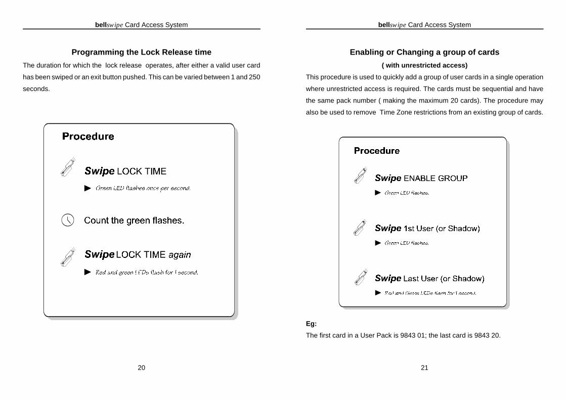
Programming the Lock Release time
The duration for which the lock release operates, after either a valid user card
has been swiped or an exit button pushed. This can be varied between 1 and 250
seconds.
bellswipe Card Access System
21
Enabling or Changing a group of cards
( with unrestricted access)
This procedure is used to quickly add a group of user cards in a single operation
where unrestricted access is required. The cards must be sequential and have
the same pack number ( making the maximum 20 cards). The procedure may
also be used to remove Time Zone restrictions from an existing group of cards.
Eg:
The first card in a User Pack is 9843 01; the last card is 9843 20.
bellswipe Card Access System
22
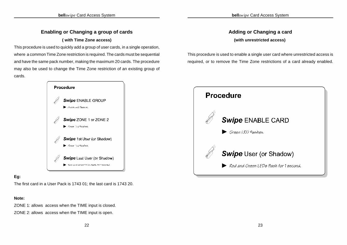
Enabling or Changing a group of cards
( with Time Zone access)
This procedure is used to quickly add a group of user cards, in a single operation,
where a common Time Zone restriction is required. The cards must be sequential
and have the same pack number, making the maximum 20 cards. The procedure
may also be used to change the Time Zone restriction of an existing group of
cards.
Eg:
The first card in a User Pack is 1743 01; the last card is 1743 20.
Note:
ZONE 1: allows access when the TIME input is closed.
ZONE 2: allows access when the TIME input is open.
bellswipe Card Access System
23
Adding or Changing a card
(with unrestricted access)
This procedure is used to enable a single user card where unrestricted access is
required, or to remove the Time Zone restrictions of a card already enabled.

bellswipe Card Access System
24
Adding or Changing a card
(with timed access)
This procedure is used to enable a single user card requiring a Time Zone
restriction, or to change the Time Zone of a card already enabled.
Notes
ZONE 1: allows access when the TIME input is closed.
ZONE 2: allows access when the TIME input is open.
bellswipe Card Access System
25
Disabling a User Card
Swiping a Shadow Card will disable the corresponding User Card ( which has the
same Pack number and User number).
Deleting all user cards
This procedure will completely disable (delete) all User cards from the system.
Please be sure this is what you want!

bellswipe Card Access System
26
The TEST LOCK card
This card will operate the lock release for a fixed 5 seconds, regardless of any
other settings. It is primarily intended as a quick and simple way of testing the
system after installation. The Card reader, lock release and ‘Active Time Zone’
are all tested with a single swipe. Swiping the card backwards tests the red LED
Comments
The lock release can also be tested directly from the CR500 Control unit. Please
refer to the Testing section on page 33.
ZONE 1: allows access when the TIME input is closed.
ZONE 2: allows access when the TIME input is open.
bellswipe Card Access System
27
Engineering Functions
CAUTION! Mains voltages present; The following procedures must only be
carried out by an Electrician or similarly competent person.
Warning
These procedures are normally only used when the system is setup at the factory.
They should only be used in the field under the manufacturer’s directions.
Restoring Factory Settings
All settings will be reset to the following defaults:
User cards: All disabled
Function cards: All disabled
Lock time: 5 seconds
Enabling the starter Pack
The 16 user cards in the starter pack are enabled with unrestricted access, as
well as, the 8 function cards.

bellswipe Card Access System
28
Notes:
Releasing the Factory Reset button prematurely during the above procedure may
cause only a partial reset (indicated by the red LED flashing for 1 second). In this
case the procedure must be repeated before adding the Starter Pack or using the
system.
bellswipe Card Access System
29
Replacing the function cards
This procedure can be used to replace the 8 function cards on the system without
affecting any user cards already present.
Notes
* Any new function card except ENABLE PACK.
The previous set of functions cards will be erased from the system.
bellswipe Card Access System
30
Troubleshooting
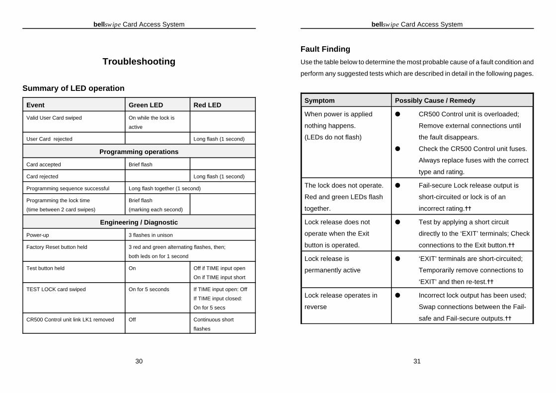
Summary of LED operation
Event Green LED Red LED
Valid User Card swiped On while the lock is
active
User Card rejected Long flash (1 second)
Programming operations
Card accepted Brief flash
Card rejected Long flash (1 second)
Programming sequence successful Long flash together (1 second)
Programming the lock time
(time between 2 card swipes)
Brief flash
(marking each second)
Engineering / Diagnostic
Power-up 3 flashes in unison
Factory Reset button held 3 red and green alternating flashes, then;
both leds on for 1 second
Test button held On Off if TIME input open
On if TIME input short
TEST LOCK card swiped On for 5 seconds If TIME input open: Off
If TIME input closed:
On for 5 secs
CR500 Control unit link LK1 removed Off Continuous short
flashes
bellswipe Card Access System
31
Fault Finding
Use the table below to determine the most probable cause of a fault condition and
perform any suggested tests which are described in detail in the following pages.
Symptom Possibly Cause / Remedy
When power is applied
nothing happens.
(LEDs do not flash)
� CR500 Control unit is overloaded;
Remove external connections until
the fault disappears.
� Check the CR500 Control unit fuses.
Always replace fuses with the correct
type and rating.
The lock does not operate.
Red and green LEDs flash
together.
� Fail-secure Lock release output is
short-circuited or lock is of an
incorrect rating.^^
Lock release does not
operate when the Exit
button is operated.
� Test by applying a short circuit
directly to the ‘EXIT’ terminals; Check
connections to the Exit button.^^
Lock release is
permanently active
� ‘EXIT’ terminals are short-circuited;
Temporarily remove connections to
‘EXIT’ and then re-test.^^
Lock release operates in
reverse
� Incorrect lock output has been used;
Swap connections between the Fail-
safe and Fail-secure outputs.^^

bellswipe Card Access System
32
The lock operates from the
test button but not the User
card.
� Check the system has been correctly
programmed for that user card.
� Check the Card Reader by refer to
page 33.
� Check the magnetic strip has not
become defective (exposure to
moisture, a strong magnetic field or
excessive abrasion).
^^ Refer to page 34 to confirm correct operation of the lock release..
bellswipe Card Access System
33
TestingEnsure the link LK1 in the CR500 Control unit is fitted before carrying out any
tests. Confirm that the red LED is not continuously flashing.
Testing the Card Reader
Swipe the TEST LOCK card through the reader:
< Check the green LED comes on for 5 seconds.(Depending on the Time Zone red may also come on)
Swipe the TEST LOCK card through the reader backwards (testing
the red LED):
< The red LED should come on for 1 second.
Warning Using the test button requires removing the lid of the
CR500 Control unit. To avoid the risk of electric shock,
care should be taken not to touch anything other than
the Test button. This operation should only be
undertaken by qualified personnel.

bellswipe Card Access System
34
Testing the Lock release outputs
Ensure the lock release is connected to the correct output (as shown in the wiring
diagram on page 3).
Press and hold the PCB TEST button
< The Lock outputs and green LED will operate whilst thebutton is held.
If the LED turns on as described, but the lock release fails to operate:
Check the lock release and its wiring by moving the lock connections to
C+,H-.The Control Unit PCB can be checked by measuring the voltage
output on the lock release pair; this should be the same as the power supply
(13.8V).
Note: the fail-safe output will have voltage present except when the TEST
button is pressed.
If pressing the TEST button causes the LEDs to flash immediately:
The power supply has been overloaded; look for either a short-circuit across
the lock release output, or check that the lock release used requires less
than 500mA @ 12V.
bellswipe Card Access System
35
Testing the Time Clock Input
ZONE 1
Set the Time Clock or key-switch to Zone 1 ( ‘TIME connection shorted).
Press the TEST button:
< Check the red and green LEDs stays on all the time thebutton is pressed.
ZONE 2
Set the Time Clock or key-switch to Zone 2 (‘TIME connection open circuit).
Press the TEST button:
< Check only the green LED stays on, while the TESTbutton is held.

bellswipe Card Access System
36
SpecificationCR500 Control Unit
Dimensions 215 mm (H) x 200 mm (W) x 70 mm (D)
Power Consumption 32VA max. @ 230V~ +10% 50Hz
Output( C + & H -) 13.8V DC @ 200mA max.
Lock outputs Fail-secure or Fail-safe
Undedicated relay
contact
13.8V DC @ 0.5A max.
connections: 1 pole changeover
(Voltage free)
switching current **1A @ 30VDC max.
Lock release time 1 - 250 seconds
Exit Input Normally open contact (must be voltage free)
Time input Normally open or closed contact (must be voltage free)
**protection must be added for Inductive loads, if used .
RH10 Card Reader
Dimensions 111 mm (H) x 38 mm (W) x 36mm (D)
Length of captive cable 2 m
Consumption 13.8V DC @ 40 mA maximum
Standards
ccThis Product complies with European Directives:
89/336/EEC for Electro-Magnetic Compatibility (EMC)
73/23/EEC for Low Voltage Systems (LVD)
Made in the United Kingdom