be installed with cover open and in - hot … · montage hydraulique montage latéral au sommet de...
TRANSCRIPT
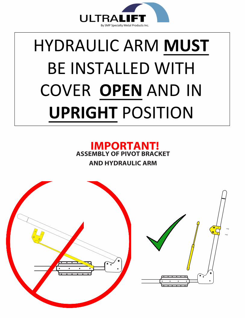
HYDRAULIC A RM MUSTBE INSTALLED WITH
COVER OPEN AND IN UPRIGHT POSITION
By SMP Specialty Metal Products Inc.
IMPORTANT!ASSEMBLY OF PIVOT BRACKET
AND HYDRAULIC ARM

Side Mount at top of spa OR Deck Mount on in-ground tubs ONLYAssembly, Installation Instructions & Parts List
ULTRALIFT HM COVER LIFTERHYDRAULIC MOUNT
PARTS LIST
SMP Specialty Metal Products Inc. 326 Watline Avenue Mississauga, ON L4Z 1X2 1-800-597-1343 www.ultrapoolandspa.com
TOOLS LISTPhillips screwdriver
Measuring tape Drill
1/8 drill bit Adjustable wrench
Nyon Washer x4
Mounting Bracket Assembly (x2) Slider Pivot Bracket (x2)3 1/4” Hook Pin (x1)Center Pole (x1)Round Pivot Arm (x2Cover Hook (x2)Foam Grip (x2)Hydraulic Arm (x2)Hydraulic Clamp (x2)
Bolt Pin (x2)Clevis Pin (x2)#10 - 5/8“ Self Tapping Screw (x24) #10 - 1” Woodscrew (x20)Ball Stud (x4)5/16 - NC NY-Lock Nut (x4)5/16 - C NY-Lock Nut (x4) (in bag with ball studs) #10-32 Button Head Machine Screw (x4) 1 1/4” Square Plastic Caps (x2)1 1/4” Round Plastic Caps (x2)Corner Support Arm (”L “Shaped) (x2)
MOUNTING BRACKET ASSEMBLY x 2
5/16 - NC NY-LOCK NUTS x4
HYDRAULIC CLAMP x 2
D
#10 - 32 BUTTON HEAD MACHINE SCREWS
#10 - 5/8” SELF-TAPPINGSCREWS
5/16 - C NY-LOCK NUT x4
HYDRAULIC ARM x 2
ATTACH AT “D” ONHYDRAULIC CLAMP
ATTACH AT “C” ON SLIDER PIVOT BRACKET
BALL STUD x4
BOLT PIN x 2
CENTER POLEx 1
SLIDER PIVOT BRACKET x 2
3 1/4” HOOK PIN x 1
#10 - 1” WOODSCREW with caps x 20
#10 - 5/8” SELF TAPPING SCREW with caps x 24
CLEVIS PIN x 2
ROUND PLASTIC CAP
x 2
SQUARE PLASTIC CAP x 2
BALL STUD X 4
ROUND PIVOT ARM x 2CORNER SUPPORT ARM (”L” SHAPED)
x 2
FOAM GRIP x 2
#10-32 BUTTON HEAD MACHINE SCREW X 4
ATTACH AT 'B' ONSLIDER PIVOT BRACKET
COVER HOOK X2
B C
INSTALLATION INSTRUCTIONS
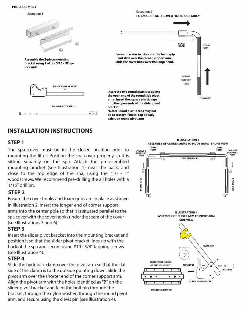
STEP 1The spa cover must be in the closed position prior to mounting the lifter. Position the spa cover properly so it is sitting squarely on the spa. Attach the preassembled mounting bracket (see Illustration 1) near the back, and close to the top edge of the spa, using the #10 - 1” woodscrews. We recommend pre-drilling the all holes with a 1/16” drill bit.
STEP 2Ensure the cover hooks and foam grips are in place as shown in Illustration 2. Insert the longer end of corner support arms into the center pole so that it is situated parallel to the spa cover with the cover hooks under the seam of the cover (see Illustrations 3 and 6)STEP 3Insert the slider pivot bracket into the mounting bracket and position it so that the slider pivot bracket lines up with the back of the spa and secure using #10 - 5/8" tapping screws (see Illustration 4).STEP 4Slide the hydraulic clamp over the pivot arm so that the flat side of the clamp is to the outside pointing down. Slide the pivot arm over the shorter end of the corner support arm. Align the pivot arm with the holes identified as "B" on the slider pivot bracket and feed the bolt pin through the bracket, through the nylon washer, through the round pivot arm, and secure using the clevis pin (see Illustration 4).
ILLUSTRATION 3ASSEMBLY OF CORNER ARMS TO PIVOT ARMS - FRONT VIEW
SUPPORT ARM
CORNER ARM
CORNER SUPPORT
CENTER POLE
PIV
OT
ARM
PIVO
T ARM
llustration 2FOAM GRIP AND COVER HOOK ASSEMBLY
Use warm water to lubricate the foam grip and slide over the corner support arm.
Slide the cover hook over the longer end.
FOAM GRIP
CORNER
SUPPORT
ARM
FOAM GRIP
ILLUSTRATION 4ASSEMBLY OF SLIDER ARM TO PIVOT ARM
SIDE VIEW
SLIDER PIVOT BRACKET
MOUNTING BRACKET
(ROTATE DEPENDING ON CHOSEN MOUNT)
B
PIVOT ARM
CLEVIS PIN
BOLT PIN
COVERHOOK
COVERHOOK
COVERHOOK
PRE-ASSEMBLY
Insert the two round plastic caps into the open end of the round side pivot arms. Insert the square plastic caps into the open ends of the slider pivot bracket.*Note: Round plastic caps may not be necessary if metal cap already exists on round pivot arm
Assemble the 2-piece mounting bracket using 2 of the 5/16 - NC ny-lock nuts.
SLIDER PIVOT BRACKET x 2
ROUND PIVOT ARM x 2
Illustration 1

COMPLETED COVER LIFTER
MOUNTING BRACKET
SLIDER PIVOT BRACKET
HYDRAULIC ARM
HYDRAULIC CLAMP
PIVOT ARM
CORNER SUPPORT
ARM
IMPORTANT!ASSEMBLY OF PIVOT BRACKET AND HYDRAULIC ARM
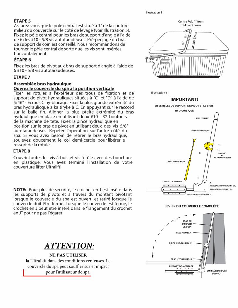
CAUTION: DO NOT USE
the UltraLift in windy conditions. The spa cover may blow over and impact the spa user.
Mid
dle
Seam
Centre Pole 1" from middle of cover
Illustration 5
Illustration 6
STEP 5Make sure the centre pole is located 1" from the middle seam of the cover on the lifter side (see Illustration 5). Attach the centre pole to the corner support arms using 6 of the #10 - 5/8 self-tapping screws. Pre-drilling the corner support arms is advised. We recommend rotating the centre pole so that the screws are inserted horizontally.
STEP 6Secure the pivot arms to the corner support arms using 6 #10 - 5/8 self-tapping screws.
STEP 7Hydraulic arm assembly:Open the spa cover to the upright position Fasten the ball studs to the outside of the hydraulic clamp and pivot bracket holes located at "C" and "D" using 5/16" - C ny-lock nuts . Attach the larger end of the hydraulic arm to the ball stud at C by pressing the end fitting over the ball stud. Align the smaller end of the hydraulic arm with the hydraulic clamp, and attach to the ball stud at D. Tighten the hydraulic clamp into place using two #10 – 32 button head machine screws. Secure the hydraulic clamp in position on the pivot arm using two of the 5/8” self-tapping screws. Repeat on the other side of the spa. If you need to remove the hydraulic arm, GENTLY pry the half-circle collar to release the spring from the ball stud.
STEP 8Cover all woodscrews and tapping screws with plastic caps. You have completed the installation of your Ultralift cover lifter
NOTE: The J - pin is inserted into the pivot brackets and through the round pivot arm when the spa cover is in the open position for added safety and removed when the cover is to be closed. When the cover is closed, the J - pin can be inserted into “J - pin storage” for safe-keeping.
PIVOT ARM
HYDRAULIC CLAMP
D
HYDRAULIC ARM
MOUNTING BRACKET
SLIDER PIVOT BRACKET
J-PIN LOCK
J-PIN STORAGE
#10 - 5/8"SELF TAPPING
SCREWS
C
B

MAKING A CLAIM:
To make a warranty claim; in the event of a defect covered by this warranty for UltraLift, contact the original retail seller and
provide original purchase receipt, any photo(s) clearly showing the defect(s) and an explanation. NO RETURNS OF MERCHANDISE WILL BE ACCEPTED UNTIL A "RETURN AUTHORIZATION NUMBER" HAS BEEN ISSUED.
The lifter will be repaired or replaced at the discretion of the Manufacturer. If necessary, the purchaser is responsible to ship any said parts back to the manufacturer. The warranty includes all Labor costs performed at the manufacturer's facility but not labor in the field. SMP will cover the cost(s) to repair and/or replacement of the items back to the retailer or seller.
Consequential Damages:SMP Specialty Metal Products Inc. will not be liable for any loss, expense, or damage other than to UltraLift, that may result from a defect in materials or workmanship. This warranty does not cover incidental damages including damage to property or injury arising from the use or inability to use this product. Manufacturer or Seller shall in no event be liable for any amount in excess of the original purchased amount. (Some Provinces / States do not allow the exclusion or limitation of incidental or consequential damages, so the above mentioned limitation may not apply to you).
It is important that you report to the Retailer from whom you purchased UltraLift, any defects as soon as they are detected. If it is impractical to report any defects to the Retailer, Contact SMP Specialty Metal Products Inc. 326 Watline Avenue, Mississauga, Ontario Canada, L4Z 1X2; Phone: 1-800-597-1343, Email: [email protected]
THE WARRANTY:SMP Specialty Metal Products Inc. warrants to you (the original purchaser) for the stated warranty term of FIVE YEARS(60 Months) from the original date of purchase, to be free from defects in material and workmanship.
UltraLift Cover Lifters will be free from defects in materials or workmanship that would cause the lifter to be inoperable innormal working conditions. Any claim made within these terms for Five years from the date of purchase will be repaired orreplaced at the option of the Manufacturer.
This is a 100% Non-Prorated Warranty on all parts for the full 5 years. Only parts excluded from the warranty are the gassprings which include a 100% One Year Warranty.
EXCLUSIONS TO WARRANTY
Lifter has been subjected to alteration, misuse or repairs by anyone other than an authorized representativeof the Manufacturer, unless written approval is provided
Damage caused by improper installation or during transportation from the seller to the purchaser
Any damage resulting from any misuse, abuse, negligence, accident or alteration, environmental, or use duringhigh winds
The warranty covers the operational use of the lifter but does not cover scratches, abrasions, rusting or any defects to the finish of the material caused by or resulting from the exposure to the environmental factors; i.e. sun, rain, chemicals or anydefects resulting from normal fading or minor deterioration.The warranty does not cover damage resulting from abuse or accidents, including but not limited to the following damage:
Use of abrasive or unapproved cleaners that could cause surface damage
Subjection to solvents or other chemicals which could deteriorate painted surfaces
Use for any other purpose than as a Spa or Hot tub cover lifter
FREIGHT DAMAGE:Any materials damaged in freight will be replaced by SMP Specialty Metal Products provided the purchaser files the appropriate claims form with the carrier, and submits copies to the manufacturer within five (5) business days of receivingthe damaged merchandise. All claims should also be reported to the seller.
by SMP Specialty Metal Products Inc.
Patent No. 2,432,833 US Patent No. 7290297B2 Patents Pending Made in Canada

By SMP Specialty Metal Products Inc.
BRAS HYDRAULIQUE DOIT ÊTRE INSTALLÉ AVEC
OUVERTE ET EN POSITION VERTICALE
IMPORTANT!ASSEMBLAGE DU SUPPORT DE PIVOT ET DU MONTANT
HYDRAULIQUE

Liste des outilsTournevis Phillips Ruban à mesurer
Perceuse 1/8 foret Clé à
molette
Support de Montage (x2) Curseur Support de Pivot (x2) 3 1/4" Pin à Crochet (x1) 1 Tringle Centrale (x1) Bras Pivotant (x2) Crochet du Couvercle (x2) Poignées en Mousse (x2) Bras Hydraulique (x2) Bride Hydraulique (x2) Rondelle en Nylon (x4)
Goupille de la Culasse (x2)Axe de Chape (x2)# 10 - 5/8 "Vis Autotaraudeuses avec Bouchons (x24) # 10 - 1" Vis à Bois avec Bouchons (x20) Pivots À Rotule (x4)5/16" Écrous - NC Nylock (x4)5/16" Écrous - C Nylock (x4) (dans un sac avec rotules)Vis Mécaniques à Tête Ronde #10-32 (x4)1 1/4" Rondes Capuchons en Plastique (x2) 1 1/4" Latérale Capuchons en Plastique(x2) Bras de Support de Coin ("L" en forme) (x2)
Liste des Pièces
2 SUPPORT DE MONTAGE
LEVIER DE COUVERCLE HM ULTRALIFT MONTAGE HYDRAULIQUE Montage latéral au sommet de la station thermale ou le pont du Mont sur cuves enterrées SEULEMENT
Instructions de Montage et d’Installation et Liste des Pièces
www.theultralift.com 1-800-597-1343
Parties
2 POIGNÉES EN MOUSSE
2 CURSEUR SUPPORT DE PIVOT
2 BRAS DE SUPPORT DE COIN (FORME DE “L”)
4 ÉCROUS - NC NYLOCK 5/16"
2 LATÉRALE CAPUCHONS EN PLASTIQUE
4 VIS MÉCANIQUES À TÊTE RONDE #10-32
2 GOUPILLE DE LA CULASSE
2 PIVOTS À ROTULE
20 VIS À BOIS AVEC BOUCHONS
1 TRINGLE CENTRALE
24 VIS AUTOTARAUDEUSES AVEC BOUCHONS #10-5/8"
CROCHET EN J 3 1/4"
2 BRAS PIVOTANTS'ATTACHE À 'B' SUR
LE SUPPORT DE PIVOT
2 AXE DE CHAPE
BRIDE HYDRAULIQUE
D
4 ÉCROUS-C NYLOCK 5/16"
2 BRAS HYDRAULIQUE
PIVOTS À ROTULE
S'ATTACHE À 'C' SUR LE SUPPORT DE PIVOT
S'ATTACHE À 'D' SUR LE ATTACHE
HYDRULIQUE
VIS MÉCANIQUES À TÊTE RONDE #10-32
VIS MÉCANIQUES À TÊTE RONDE #10-32
2 RONDES CAPUCHONS EN PLASTIQUE
2 CROCHET DU COUVERCLE
RONDELLE EN NYLON X4

Le couvercle du spa doit être en position fermée avant le montage du levier. Placer le couvercle du spa pour qu'il ne se repose carrérment sur la spa. Fixez le support de montage pré-assemblé (voir Illustration 1) prés de l'arrière, et à proximité du bord supérieur du spa, en utilisant les #10 - 5/8 vis à bois 1. Nous recommandons avant de percer les trous avec une mèche de 1/16" de forage.
Instructions d’InstallationÉTAPE 1
ÉTAPE 3Insérer le support curseur de pivot dans le support de montage et le positionner de sorte que les lignes de la console de pivot de curseur vers le haut avec le dos de la station thermale et de sécuriser en utilisant #10 - 5/8 vis parker (voir Illustration 4).
ÉTAPE 2Vérifiez que le capot crochets et poignées en mousse sont en place, comme indiqué dans l'illustration 2. Insérez l'extrémité longue de bras de support de coin dans le pôle central de sorte qu'il se trouve paralléle à la couverture du spa avec les crochets de couverture en vertu de la couture de la couverture (voir Illustrations 3 et 6).
ILLUSTRATION 4 VUE DE CÔTÉ - ASSEMBLÉE DES
SLIDER ARM PIVOTER ARM
AXE DE CHAPE
(ROULEMENT EN FONCTION CHOISI MOUNT)
SUPPORT DE MONTAGE
CURSEUR SUPPORT DE PIVOT
B
BRAS PIVOTANT
GOUPILLE DE LA CULASSE
Avant le montage: Utilisez de l'eau chaude pour lubrifier la poignée en mousse et glisser sur le bras de support de coin.
ASSEMBLAGE DU POIGNÉES EN MOUSSE
POIGNÉES EN MOUSSE
POIGNÉES EN MOUSSE
BRAS DE SUPPORT DE COIN
ILLUSTRATION 3VUE DE FACE -
ASSEMBLEE DES ARMES COIN PIVOTER ARMS
TRINGLE CENTRALE
COUVERCLE DE SPA
BRAS DE SUPPORT DE COIN
BRA
S PI
VOTA
NT
BRAS DE SUPPORT DE COIN
BRAS PIVO
TAN
T
ÉTAPE 4Faites glisser la pince hydraulique sur le bras de pivot de sorte que le côté plat de la pince est à l'extérieur de pointage vers la bas. Faites glisser le bras de pivot sur le bras de support de coin. Aligner le bras de pivot avec les trous identifiés comme "B" sur le support coulissant de la culasse à travers le support, à travers le bras de pivot rond, et de chape (voir Illustration 4).
CROCHETS DU COUVERCLE
CROCHETS DU COUVERCLE
CROCHETS DU COUVERCLE
PRÉMONTAGE
Illustration 1
Assemblez le support de montage 2 pièces en utilisant 2 des 5/16 - NC ny-blocage.
Insérez les deux bouchons en plastique ronds dans l'extrémité ouverte des rondes bras pivotants de côté. Insérer les bouchons en plastique carrés dans les extrémités ouvertes du support coulissant de pivot. Remarque: des bouchons en plastique rondes peuvent ne pas être nécessaire si le bouchon de métal existe déjà sur le bras de pivot rond.
CURSEUR SUPPORT DE PIVOT x 2
BRAS DE PIVOT ROND x 2
Illustration 2
LEVIER DU COUVERCLE COMPLÉTÉ
SUPPORT DE MONTAGE
BRAS HYDRAULIQUE
BRIDE HYDRAULIQUE
BRAS PIVOTANT
BRAS DE SUPPORT DE COIN
CURSEUR SUPPORT DE PIVOT
ATTENTION: NE PAS UTILISER
la UltraLift dans des conditions venteuses. Le couvercle du spa peut souffler sur et impact
pour l'utilisateur de spa.
ÉTAPE 5Assurez-vous que le pôle central est situé à 1" de la couture milieu du couvercle sur le côté de levage (voir Illustration 5). Fixez le pôle central pour les bras de support d'angle à l'aide de 6 des #10 - 5/8 vis autotaradeuses. Pré-perçage du bras de support de coin est conseillé. Nous recommandons de tourner le pôle central de sorte que les vis sont insérées horizontalement.ÉTAPE 6Fixez les bras de pivot aux bras de support d'angle à l'aide de 6 #10 - 5/8 vis autotaraudeuses.ÉTAPE 7Assemblée bras hydraulqueOuvrez le couvercle du spa à la position verticaleFixer les rotules à l'extérieur des trous de fixation et de support de pivot hydrauliques situées à "C" et "D" à l'aide de 5/46" - Écrous C ny-blocage. Fixer la plus grande extrémité du bras hydraulicque à ka tiryke à C. En appuyant sur le raccord sur la balle fin. Aligner la plus pteite extrémité du bras hydraulique en place en utilisant deux #10 - 32 bouton vis de la machine de tête. Fixez la pince hydraulique en position sur le bras de pivot en utilisant deux des vis 5/8" autotaraudeuses. Répéter l'opération sur l'autre côté du spa. Si vous avex besoin de retirer le bras hydraulique, soulevez doucement le col demi-cercle pour libérer le ressort de la rotule.ÉTAPE 8Couvrir toutes les vis à bois et vis à tôle avec des bouchons en plastique. Vous avez terminé l'installation de votre couverture lifter Ultralift!
NOTE: Pour plus de sécurité, le crochet en J est inséré dans les supports de pivots et à travers du montant pivotant lorsque le couvercle du spa est ouvert, et retiré lorsque le couvercle doit être fermé. Lorsque le couvercle est fermé, le crochet en J peut être inséré dans le “rangement du crochet en J” pour ne pas l’égarer.
Mid
dle
Seam
Centre Pole 1" from middle of cover
Illustration 5
IMPORTANT!ASSEMBLÉE DE SUPPORT DE PIVOT ET LE BRAS
HYDRAULIQUE
Illustration 6
BRAS PIVITANT
BRIDE HYDRAULIQUE
D
BRAS HYDRAULIQUE
SUPPORT DE MONTAGE
CURSEUR SUPPORT DE PIVOT
BLOCAGE DU CROCHET EN J
RANGEMENT DU CROCHET EN J
#10 - 5/8"VIS
AUTOTARAUDEUSES
C
B

FAIRE UNE DEMANDE:
Pour faire une demande de garantie; en cas d'un défaut couvert par cette garantie pour UltraLift, contacter le vendeur initial de détail et fournir un reçu d'achat original, la photo(s) montrant clairement le défaut(s) et une explication. AUCUN RETOUR DE MARCHANDISE seront acceptées jusqu'à un "numéro d'autorisation de retour" a été délivré.
Le dispositif de levage sera réparé ou remplacé à la discrétion du fabricant. Si nécessaire, l'acheteur est responsable d'expédier des dites parties au fabricant. La garantie couvre tous les coûts du travail effectués à l'usine du fabricant , mais pas le travail sur le terrain. SMP couvrira le coût(s) pour réparer et / ou le remplacement des pièces au détaillant ou le vendeur.
FRET DOMMAGE :Les matériaux endommagés dans le fret seront remplacés par SMP Specialty Metal Products fournis l'acheteur dépose les demandes appropriées forment avec le transporteur, et soumet des copies au fabricant dans les cinq ( 5 ) jours ouvrables suivant la réception de la marchandise endommagée. Toutes les demandes doivent également être signalés au vendeur.
LA GARANTIE:
SMP Specialty Metal Products Inc. vous garantit ( l'acheteur d'origine ) pour la période de garantie indiquée de cinq ans (60 mois) à partir de la date d'achat originale , sont exempts de défauts de matériaux et de fabrication
UltraLift Cover Lifters sera exempt de défauts de matériaux ou de fabrication qui causent le levage d'être inopérant dansdes conditions de travail normales. Toute réclamation faite dans ces conditions pendant cinq ans à compter de la date d'achat sera réparé ou remplacé au choix du fabricant.
Cette garantie est une garantie non proportionnelle 100% sur toutes les parties pour les 5 années complètes . Seules les pièces exclues de la garantie sont le gaz ressorts qui comprennent 100% Garantie d'un an.
EXCLUSIONS DE GARANTIE:
Lifter a été soumis à modification, usage impropre ou de réparation par une personne autre qu'un représentant autorisé du fabricant, sauf autorisation écrite est fournie
Les dommages causés par une mauvaise installation ou lors du transport du vendeur à l'acheteur
Tout dommage résultant d'une mauvaise utilisation, d'abus, de négligence, d'un accident ou d'altération, de l'environnement, ou de l'utilisation au cours vents forts
La garantie couvre l'utilisation opérationnelle du dispositif de levage, mais ne couvre pas les rayures, les abrasions, la rouille ou les défauts de la finition du matériel causé par ou résultant de l'exposition aux facteurs environnementaux; à-dire le soleil, la pluie, les produits chimiques ou tout défauts résultant d'une décoloration normale ou une détérioration mineure.La garantie ne couvre pas les dommages résultant d'un abus ou d'accidents, y compris mais sans s'y limiter les dommages suivants:
L'utilisation de nettoyants abrasifs ou non approuvées qui pourraient causer des dommages de surface
Assujettissement aux solvants ou autres produits chimiques qui peuvent endommager les surfaces peintes
L'utilisation à toute autre fin que comme un spa ou un jacuzzi couvert lifter
by SMP Specialty Metal Products Inc.
Patent No. 2,432,833 US Patent No. 7290297B2 Patents Pending Made in Canada
Dommages conséquents:SMP Specialty Metal Products Inc. ne sera pas responsable de toute perte, dépense ou dommage autre que de UltraLift , qui peut résulter d'un défaut de matériaux ou de fabrication. Cette garantie ne couvre pas les dommages accessoires, y compris les dommages matériels ou corporels résultant de l'utilisation ou de l'impossibilité d'utiliser ce produit. Fabricant ou vendeur ne doivent en aucun cas être tenu responsable pour tout montant en sus du montant de l'achat initial. (Certaines provinces / États ne permettent pas l' exclusion ou la limitation des dommages indirects ou consécutifs, la limitation mentionnée ci-dessus peuvent ne pas vous).Il est important que vous rapportez au détaillant où vous avez acheté UltraLift, tout défaut dès qu'ils sontdétecté. S'il est impossible de signaler tout défaut chez le détaillant, Contact SMP Specialty Metal Products Inc.326 Watline Avenue, Mississauga, ON L4Z 1X2, PH: 1-800-597-1343, Email: [email protected]