automatic acquisition and use of multimodal …etd.lib.metu.edu.tr/upload/12608462/index.pdf ·...
TRANSCRIPT

AUTOMATIC ACQUISITION AND USE OF MULTIMODAL MEDICALDEVICE OBSERVATIONS BASED ON ISO/IEEE 11073 AND HL7
STANDARDS
A THESIS SUBMITTED TOTHE GRADUATE SCHOOL OF NATURAL AND APPLIED SCIENCES
OFMIDDLE EAST TECHNICAL UNIVERSITY
BY
ALPER OKCAN
IN PARTIAL FULFILLMENT OF THE REQUIREMENTSFOR
THE DEGREE OF MASTER OF SCIENCEIN
COMPUTER ENGINEERING
JUNE 2007

Approval of the Graduate School of Natural and Applied Sciences.
Prof. Dr. Canan OzgenDirector
I certify that this thesis satisfies all the requirements as a thesis for the degreeof Master of Science.
Prof. Dr. Volkan AtalayHead of Department
This is to certify that we have read this thesis and that in our opinion it is fullyadequate, in scope and quality, as a thesis for the degree of Master of Science.
Prof. Dr. Asuman DogacSupervisor
Examining Committee Members
Prof. Dr. Ozgur Ulusoy (Bilkent,CENG)
Prof. Dr. Asuman Dogac (METU,CENG)
Prof. Dr. I. Hakkı Toroslu (METU,CENG)
Assoc. Prof. Dr. Nihan Kesim Cicekli (METU,CENG)
Gokce Banu Laleci Erturkmen (METU,SRDC)

I hereby declare that all information in this document has been obtainedand presented in accordance with academic rules and ethical conduct. Ialso declare that, as required by rules and conduct, I have fully cited andreferenced all material and results that are not original to this work.
Name, Last name: ALPER OKCAN
Signature:

ABSTRACT
AUTOMATIC ACQUISITION AND USE OF MULTIMODAL MEDICAL
DEVICE OBSERVATIONS BASED ON ISO/IEEE 11073 AND HL7
STANDARDS
Okcan, Alper
M.Sc., Department of Computer Engineering
Supervisor: Prof. Dr. Asuman Dogac
June 2007, 81 pages
The delivery of quality healthcare to all citizens at reasonable costs is an
important challenge. With the increase in the aging population, the costs of
managing chronic diseases increase. Today, healthcare services tend to shift
from recovery to prevention. Remote healthcare monitoring is crucial for pre-
vention and monitoring of chronic diseases since they require continuous and
long-term monitoring. The advances in networking, mobile communications and
medical device technologies offer a great potential to realize remote healthcare
monitoring. However, seamless integration of multi-modal medical devices to
the existing healthcare information systems is necessary for the automated use
of medical device observations in related applications.
The thesis addresses the automatic acquisition and use of multi-modal med-
ical device observations in healthcare information systems. The interoperability
of medical devices with healthcare information systems requires both physical
connectivity and application level interoperability. Therefore, the thesis concen-
iv

trates on both the medical device domain and the interoperability efforts on the
existing healthcare information systems. It provides an interoperability solution
based on ISO/IEEE 11073 and HL7 standards. This work is also realized the
automatic acquisition and use of multi-modal medical device observations in an
intelligent healthcare monitoring and decision support system which is devel-
oped as a part of the IST-027074 SAPHIRE project funded by the European
Commission.
Keywords: Medical Devices, Semantic Interoperability, Remote Healthcare Mon-
itoring, IEEE 11073, HL7,IHE PCD Profile, Ambient Intelligence, Sensor Net-
works
v
OZ
ISO/IEEE 11073 VE HL7 STANDARTLARI ILE MEDIKAL CIHAZ
GOZLEMLERININ OTOMATIK EDINIMI VE KULLANIMI
Okcan, Alper
Yuksek Lisans, Bilgisayar Muhendisligi Bolumu
Tez Yoneticisi: Prof. Dr. Asuman Dogac
Haziran 2007, 81 sayfa
Saglık servislerinin tum vatandaslara uygun maliyetlerle saglanması oldukca
zordur. Ozellikle yaslı insan nufusunun artısı ile birlikte kronik hastalıkların
bakım maliyetleri de artmaktadır. Gunumuzde, iyilestirmeden cok, onleme
dayalı saglık servislerine yonelim vardır. Kronik hastalıkların tedavisi devamlı
ve uzun sureli gozlem gerektirdiginden, uzaktan saglık gozlemi bu hastalıkların
gozlemlenmesi ve onlenmesi icin oldukca onemlidir. Bilgisayar agları, mobil
iletisim ve medikal cihaz teknolojilerindeki ilerlemelerle birlikte uzaktan saglık
gozlemi de artık mumkun olmaktadır. Fakat, farklı medikal cihazların mev-
cut saglık sistemlerine entegrasyonu, medical cihaz gozlemlerinin ilgili uygula-
malarda otomatik kullanımı acısından oldukca onemlidir.
Tez calısması, farklı medikal cihaz gozlemlerinin saglık sistemlerince otomatik
edinimini ve kullanımını amaclamaktadır. Medikal cihazların saglık sistemleriyle
birlikte calısabilirligi hem fiziksel baglantı hem de uygulama katmanında birlikte
calısabilirlik gerektirir. Bu yuzden, tez calısması hem medikal cihazları hem de
mevcut saglık sistemlerini incelemektedir. Bu calısmada ISO/IEEE 11073 ve
vi

HL7 standartlarına baglı bir cozum sunulmustur. Ayrıca bu tez calısması ile,
medikal cihazlardan gelen gozlemlerin, Avrupa Komisyonu tarafından destek-
lenen IST-027074 SAPHIRE projesi kapsamında gerceklestirilen akıllı saglık
gozlemi ve karar destek sistemine otomatik entegrasyonu saglanmıstır.
Anahtar Kelimeler: Medikal Cihazlar, Birlikte Calısabilirlik, Uzaktan Saglık
Gozlemlemesi, IEEE 11073, HL7, IHE PCD Profili, Cevresel Zeka, Sensor Agları
vii

To my family
viii

ACKNOWLEDGMENTS
I am honored to present my special thanks and deepest gratitude to my super-
visor Prof. Dr. Asuman DOGAC for all her guidance and support during this
study.
I would like to thank Software Research and Development Center team for their
support and patience during this study.
Finally, I would like to thank my family for all their life-long support.
ix

TABLE OF CONTENTS
ABSTRACT . . . . . . . . . . . . . . . . . . . . . . . . . . . . . . . . . iv
OZ . . . . . . . . . . . . . . . . . . . . . . . . . . . . . . . . . . . . . . . vi
DEDICATION . . . . . . . . . . . . . . . . . . . . . . . . . . . . . . . . viii
ACKNOWLEDGMENTS . . . . . . . . . . . . . . . . . . . . . . . . . . ix
TABLE OF CONTENTS . . . . . . . . . . . . . . . . . . . . . . . . . . x
LIST OF TABLES . . . . . . . . . . . . . . . . . . . . . . . . . . . . . . xii
LIST OF FIGURES . . . . . . . . . . . . . . . . . . . . . . . . . . . . . xiii
CHAPTER
1 INTRODUCTION . . . . . . . . . . . . . . . . . . . . . . . . . 1
2 RELATED WORK . . . . . . . . . . . . . . . . . . . . . . . . . 5
3 ENABLING TECHNOLOGIES . . . . . . . . . . . . . . . . . . 10
3.1 ISO/IEEE 11073 Point-of-care Medical Device Commu-nication . . . . . . . . . . . . . . . . . . . . . . . . . . . 10
3.1.1 ISO/IEEE 11073 Domain Information Model . 13
3.1.2 ISO/IEEE 11073 Nomenclature . . . . . . . . 14
3.2 Health Level Seven . . . . . . . . . . . . . . . . . . . . . 15
3.2.1 Message Framework . . . . . . . . . . . . . . . 16
3.2.2 Observation Reporting Trigger Events . . . . . 18
3.3 Integrating the Healthcare Enterprise . . . . . . . . . . 19
3.3.1 IHE Device Enterprise Communication Profile 21
4 PROVIDING AUTOMATED ACQUISITION OF MULTIMODALMEDICAL DEVICE OBSERVATIONS BY HEALTHCARE IN-FORMATION SYSTEMS . . . . . . . . . . . . . . . . . . . . . 23
x

4.1 Design Issues . . . . . . . . . . . . . . . . . . . . . . . . 23
4.2 Device Interface Interoperability . . . . . . . . . . . . . 25
4.2.1 Virtual Medical Object Generation . . . . . . . 26
4.2.2 Defining Data Mediation from Proprietary Mes-sages . . . . . . . . . . . . . . . . . . . . . . . 32
4.2.3 Data Mediation in the Mapping Engine . . . . 33
4.3 Observation Reporting Interface Interoperability . . . . 34
4.3.1 HL7 Unsolicited Observation Message . . . . . 36
5 REALIZATION OF THE CONCEPTS FOR THE AUTOMATEDUSE OF MEDICAL DEVICE OBSERVATIONS IN THE SAPHIREPROJECT . . . . . . . . . . . . . . . . . . . . . . . . . . . . . . 39
5.1 Saphire Medical Sensors . . . . . . . . . . . . . . . . . . 40
5.2 Data Mediation between HL7 and GLIF . . . . . . . . . 44
6 CONCLUSION . . . . . . . . . . . . . . . . . . . . . . . . . . . 47
REFERENCES . . . . . . . . . . . . . . . . . . . . . . . . . . . . . . . . 48
APPENDICES . . . . . . . . . . . . . . . . . . . . . . . . . . . . . . . . 52
A XML SCHEMA OF BLOOD PRESSURE SENSOR MESSAGES 52
B XML MESSAGE OF A BLOOD PRESSURE SENSOR OBSER-VATION . . . . . . . . . . . . . . . . . . . . . . . . . . . . . . . 55
C MAPPING FILE GENERATED FOR THE BLOOD PRESSURESENSOR . . . . . . . . . . . . . . . . . . . . . . . . . . . . . . . 57
D UNSOLICITED OBSERVATION MESSAGE TRANSFORMEDFOR THE BLOOD PRESSURE SENSOR OBSERVATION . . 65
E GLIF MESSAGE TRANSFORMED FOR THE BLOOD PRES-SURE SENSOR OBSERVATION . . . . . . . . . . . . . . . . . 66
F XML SCHEMA OF PULSE OXIMETER MESSAGES . . . . . 68
G XML MESSAGE OF A PULSE OXIMETER OBSERVATION . 71
H MAPPING FILE GENERATED FOR THE PULSE OXIMETERSENSOR . . . . . . . . . . . . . . . . . . . . . . . . . . . . . . . 72
I UNSOLICITED OBSERVATION MESSAGE TRANSFORMEDFOR THE PULSE OXIMETER SENSOR OBSERVATION . . 79
J GLIF MESSAGE TRANSFORMED FOR THE PULSE OXIME-TER SENSOR OBSERVATION . . . . . . . . . . . . . . . . . . 80
xi

LIST OF TABLES
3.1 Set of Semantic Concepts for Medical Device Differentiation . . 153.2 ADT-A01 Event Segments . . . . . . . . . . . . . . . . . . . . . 173.3 MSH Segment Attributes . . . . . . . . . . . . . . . . . . . . . . 18
4.1 OBX Segment Details . . . . . . . . . . . . . . . . . . . . . . . 37
xii

LIST OF FIGURES
1.1 Medical Device Observation Communication . . . . . . . . . . . 3
3.1 Conceptual Model of an ISO/IEEE 11073 Conformant MedicalDevice . . . . . . . . . . . . . . . . . . . . . . . . . . . . . . . . 12
3.2 ISO/IEEE 11073 Medical Package Conceptual Model . . . . . . 133.3 Nomenclature Attribution Example . . . . . . . . . . . . . . . . 153.4 A Sample ADT-A01 Message . . . . . . . . . . . . . . . . . . . 183.5 Unsolicited Observation Message . . . . . . . . . . . . . . . . . 203.6 Device Enterprise Communication Profile . . . . . . . . . . . . . 22
4.1 Communication Architecture of Related Domains . . . . . . . . 244.2 Virtual Medical Device Creation . . . . . . . . . . . . . . . . . . 304.3 Numeric Metric Creation . . . . . . . . . . . . . . . . . . . . . . 314.4 Proprietary Message Schema Panel . . . . . . . . . . . . . . . . 334.5 Data Transformation for Systolic Blood Pressure . . . . . . . . . 344.6 Part of a Mapping File Representing Blood Pressure Sensor . . 35
5.1 Step 1 - Display Input XML Schema . . . . . . . . . . . . . . . 415.2 Medical Device System Type Selection . . . . . . . . . . . . . . 425.3 Patient Demographics Mapping . . . . . . . . . . . . . . . . . . 435.4 Virtual Medical Device Creation for Blood Pressure Sensor . . . 445.5 Metric Creation for Systolic Blood Pressure . . . . . . . . . . . 455.6 Sample Design of an XSL Transformation between HL7 and GLIF 46
xiii

CHAPTER 1
INTRODUCTION
The delivery of quality healthcare to all citizens at reasonable costs is an im-
portant challenge. “Healthcare expenditure in Europe is already significant and
rising faster than overall economic growth itself [1]”. With the increase in the
aging population of Europe, the costs of managing chronic diseases increase.
Healthcare services are shifting from concentrating on illness to wellness and
recovery to prevention. Remote healthcare monitoring is crucial for preven-
tion and monitoring of chronic diseases since they require continuous, long-term
monitoring, rather than episodic assessments [2]. Also, automated monitoring
of citizens at their home would decrease the workload of medical practitioners.
Therefore, clinical use of medical device observations at remote locations would
improve the healthcare workflow, reduce medical errors, reduce healthcare costs
and improve the quality of care.
The advances in networking, mobile communications and medical device
technologies offer a great potential to realize remote chronic disease monitoring.
However, seamless integration of multi-modal medical devices to the existing
healthcare systems is an important problem to be solved.
Today, there are several efforts to store and use lifetime clinical data of a pa-
tient during medical decision processes. The idea to create an Electronic Health
Record (EHR) for a patient which stores all observations made and procedures
1

performed during the provision of care, requires integration of all healthcare
systems to communicate clinical data between each other. The simplest ISO
definition of an EHR is defined as “a repository of information regarding the
health of a subject of care in computer processable form, stored and transmit-
ted securely, and accessible by multiple authorized users. It has a commonly
agreed logical information model which is independent of EHR systems. Its
primary purpose is the support of continuing, efficient and quit contains infor-
mation which is retrospective, concurrent and prospective” [3].
The information in EHRs are generated, stored and used at different places
and at different points in time during the lifetime of the patient. Although there
is a single logical EHR for a patient storing all of his/her medical information,
there may be multiple physical EHRs distributed depending on the architec-
ture choices of different healthcare solutions. The clinical data stored related to
the patient may be needed at any instant of time for the treatment of patient.
Therefore, interoperability of EHR infrastructures between each other and with
other domains such as radiology information systems, diagnostic imaging sys-
tems, point of care systems, laboratory information systems must be supported
in order to create integrated healthcare systems. All these domains have different
special requirements. In addition, most of the systems use existing applications
developed by different vendors with different syntax and semantics. Therefore,
exchange of standardized messages is required for interoperability of systems.
Medical devices are essential to the practice of modern healthcare services.
In addition to the hospitals and specialized care units, medical devices are be-
coming popular for remote healthcare monitoring (homecare systems) with the
latest advances in wireless communication technology. However, despite health-
care systems are becoming more dependent on specialized medical devices, the
integration of these devices makes existing communication problems more com-
plex. In recent years the area of medical device communication has seen a con-
vergence of the various disparate health informatics standards efforts to solve
the problem of enabling real-time medical device communications. Since medical
2

Figure 1.1: Medical Device Observation Communication
devices produce important observations during the provision of care, the seam-
less communication of medical device derived information into the EHR systems
is necessary [4]. Networked medical device systems will support the widespread
clinical use of medical device data and produce complete and accurate electronic
health records, improve workflow, reduce medical errors, and reduce healthcare
costs [5].
The aim of this work is to automate the acquisition and use of multi-modal
medical device observations in order to improve the continuity of care. This
interoperable communication infrastructure requires both physical connectiv-
ity of devices and application level interoperability. “The physical connectivity
speaks to reliable and secure data transfer, where a system must detect the
presence of a new device and negotiate a communication protocol. Application-
level interoperability allows devices to synchronize their operational behavior
and working states, understanding each other by means of a common message
syntax, data types, encoding rules, and nomenclature [2]”. The application level
interoperability also includes the seamless communication with the healthcare
information systems. Figure 1.1 presents the medical device observation com-
munication architecture. There is a data manager located between two critical
interfaces along the communication line. The duty of the data manager is to
log, store, process and forward the incoming data to the receiver end. The first
critical interface is the device interface which connects the medical devices to
the data manager. Once the data is retrieved by the data manager, it must be
3

forwarded to the receiving end points; hospital information systems, laboratory
systems, EHRs, etc. As illustrated in the figure, there are several standard-
ization efforts used within both of the medical device domain and the hospital
information systems domain. Therefore, different methods must be facilitated
for achieving interoperability along the two interfaces; device interface and the
observation reporting interface (ORI).
In order to achieve plug-and-play communication between medical devices,
there are various standardization efforts to be detailed within the next chapters.
These efforts can also be used to achieve interoperability between the medical
devices and the data manager along the device interface. In order to achieve
interoperability along the ORI, the hospital information system domain must be
analyzed. The thesis work concentrates on both of the interfaces and proposes
novel ideas along the device interface. The work developed in the thesis is part
of the “Saphire: Intelligent Healthcare Monitoring based on Semantic Interoper-
ability Platform” project, which is funded by the European Commission, under
the 6th framework for Research and Development [6].
This thesis is organized as follows: Chapter 2 summarizes the related work
by emphasizing the innovative aspects of the proposed solution. In Chapter 3
the main technologies that have been used in this thesis are presented. Chapter
4 is devoted to the description of the solution proposed for achieving automated
acquisition and use of medical device observations in healthcare information
systems. Chapter 5 describes the realization of the proposed solution within the
Saphire project. Finally, Chapter 6 concludes the thesis.
4
CHAPTER 2
RELATED WORK
The need of an architecture for the automatic acquisition of medical device ob-
servations by clinical information systems was identified in early 1980s. The
IEEE (Institute of Electrical and Electronic Engineers, USA) developed a stan-
dard in this area, called the “Medical Information Bus (MIB)” [7]. This first
well-known effort was notified for its low adoption by medical device manufactur-
ers due to low clinical demand, complexity and hardware requirements brought
by the standard. IEEE initiated IEEE 1073 group and continued on efforts to
standardize and improve lower layers defined in MIB and adding work on upper
layers of the seven layer ISO communication model.
CEN also developed two related standards for point-of-care device communi-
cation; “ENV 13734:2000 Health informatics - Vital signs information represen-
tation” (VITAL) and “ENV 13735:2000 Health informatics - Interoperability of
patient connected medical devices” (INTERMED). VITAL standard “addresses
the definition and structuring of information that is communicated or referred
to in communication between application entities” [8]. The standard specifies
the interchange of vital signs information between medical devices and clinical
information systems. INTERMED specifically addresses medical devices com-
munication and specifies a communication controller model that should be used
by a set of applicable devices given in the standard [9].
5

“Point-of-Care Connectivity” (POCT) standard provides the basis for multi-
vendor, seamless interoperability between point-of-care devices, data managers,
and clinical results management systems [10]. This standard specifies interfaces
and protocols between medical devices and clinical information systems.
CEN, ISO and IEEE jointly published a single set of standards for point-
of-care device communication called ISO/IEEE 11073. The set of standards
include the previous work of all the three standardization bodies. Following
standards are published within ISO/IEEE 11073 family of standards:
• ISO/IEEE 11073-10101:2004(E) Health Informatics - Point-of-care medi-
cal device communication - Part 10101: Nomenclature
• ISO/IEEE 11073-10201:2004(E) Health Informatics - Point-of-care medi-
cal device communication - Part 10201: Domain Information Model
• ISO/IEEE 11073-20101:2004(E) Health Informatics - Point-of-care medi-
cal device communication - Part 20101: Application Profile - Base Stan-
dard
• ISO/IEEE 11073-30200:2004(E) Health Informatics - Point-of-care medi-
cal device communication - Part 30200: Transport Profile - Cable Con-
nected
• ISO/IEEE 11073-30300:2004(E) Health Informatics - Point-of-care medi-
cal device communication - Part 30300: Transport Profile - Infrared Wire-
less
Although the work accelerated with this joint family of standards, still adop-
tion of the standards by medical device manufacturers has been slow. Manu-
facturers prefer to produce proprietary solutions which work exclusively with
their vendor specific software. The incompatibility of different vendor products
requires duplicate work on the network. The thesis work is based on the joint
family of standards of ISO/IEEE 11073.
6

In addition to the interoperability efforts of medical devices within each
other, automatic acquisition of medical device observations by the healthcare
information systems is crucial. Hospital information systems are referred as
core systems handling basic patient data and keep track of patient stay and
phases of treatment in different departments [11]. Today, these systems are
also enhanced to provide healthcare services to ease medical practitioners work.
As a result, hospital information systems must be capable of communicating
clinical data with various healthcare actors such as EHR repositories, public
health services, and specialized information systems. Exchange of standardized
messages is required for interoperability of different healthcare systems. Groups
of system vendors and users started to develop standards for message exchange
between clinical systems. One of these consortia was called “Health Level 7”
(HL7) with reference to the application layer in the ISO/OSI reference model.
HL7 is the most successful and widely in use for hospital information system
communication and for interfacing between hospitals, insurance companies and
public health organizations [11].
“Data sharing among local hospitals is being increasingly realized with the
proliferation of the healthcare information system interoperability standard,
Health Level Seven (HL7)” [12]. The thesis work also concentrates on HL7
for interfacing between medical devices and hospital information systems.
There are also ongoing research efforts on medical device interoperability. In
[13], a wearable, portable monitoring health system was developed. This work
aims to provide plug-and-play sensor units complying with Bluetooth standard.
The system evaluates the connection between the data loggers and a set of
wearable medical sensors. However, integration of the vital signs data coming
from the sensors to the clinical information systems is not addressed in this
study.
In a similar work [14], a Bluetooth-enabled personal monitoring system and
a plug-and-play pulse oximeter were developed. The architecture proposed con-
sists of a base station, a data logger, and a medical sensor. The communication
7

between the sensor and the data logger is achieved with Bluetooth technology.
The data is forwarded to the base station on which activity viewer software is
deployed. The viewer which was used in the prototype was proprietary software
that was conformant to the incoming data, therefore semantic interoperability
of the incoming data with the clinical application was not considered within this
work.
[2] discusses the design and development of a plug-and-play system for home
care by adopting IEEE 1073 MIB standard. The prototype developed demon-
strates a proof of concept system on which device-to-device interoperability was
achieved using MIB. The proposed work in the paper must be enhanced to
promote seamless data access by clinical systems.
In [12], an extension was made to forward the data in an HL7 compliant
format to the patients EHR in a remote location. A similar approach to this
extension is followed within the thesis work. However, the interoperability of
vendor specific multi-modal medical devices is an important enhancement of the
thesis work.
There are also industry efforts in medical device connectivity area in recent
years. IBM Research Center is working on “Personal Care Connect” (PCC)
platform in order to facilitate remote monitoring of patients. Currently, PCC
platform support only vendors who request to integrate their devices with PCC
[15]. In USA, the “Medical Device Plug and Play (MD PnP) interoperability
program was established in 2004. MD PnP aims to lead adoption of open stan-
dards and technology for networking medical devices to support clinical solutions
for improving patient safety and healthcare efficiency [5].
The thesis work proposes to enhance these approaches with respect to two
aspects. First, the interconnected medical devices within the previous works
must be interoperable with the clinical information systems, laboratory systems,
electronic healthcare records, etc. The legacy medical devices must also be
considered since there are different vendor specific devices already deployed to
different application environments. Therefore, the interoperability of a medical
8

device that is not conformant to ISO/IEEE 11073 or a specific standard to a
clinical information system is also considered within the thesis work.
9

CHAPTER 3
ENABLING TECHNOLOGIES
This section provides the enabling technologies used in the thesis work. The en-
abling technologies with respect to different aspects of the interoperability issues
between medical device domain and the hospital information systems domain
are detailed. First, the ISO/IEEE 11073 standards family is described for the
interoperability among the medical devices. HL7 is also detailed in this section
to provide information on the acquisition of observation data by the hospital
information systems. Finally, Integrating the Healthcare Enterprise (IHE) ap-
proach is presented which provides integration profiles for the integration of the
two domains.
3.1 ISO/IEEE 11073 Point-of-care Medical Device Com-
munication
The need of an architecture for the automatic acquisition of medical device ob-
servations by clinical information systems was identified in early 1980s. Starting
with the Medical Information Bus (MIB) developed by IEEE in 1984, there are
various standardization efforts in medical device domain. The thesis work con-
centrates on ISO/IEEE 11073 which was approved in 2003 by CEN, ISO and
IEEE as a joint set of standards for point-of-care device communication. The
10

reason for choosing ISO/IEEE 11073 is not only its widely acceptance but also
its complementation efforts with the existing well known standards.
Following standards are published within ISO/IEEE 11073 family of stan-
dards:
• ISO/IEEE 11073-10101:2004(E) Health Informatics - Point-of-care medi-
cal device communication - Part 10101: Nomenclature
• ISO/IEEE 11073-10201:2004(E) Health Informatics - Point-of-care medi-
cal device communication - Part 10201: Domain Information Model
• ISO/IEEE 11073-20101:2004(E) Health Informatics - Point-of-care medi-
cal device communication - Part 20101: Application Profile - Base Stan-
dard
• ISO/IEEE 11073-30200:2004(E) Health Informatics - Point-of-care medi-
cal device communication - Part 30200: Transport Profile - Cable Con-
nected
• ISO/IEEE 11073-30300:2004(E) Health Informatics - Point-of-care medi-
cal device communication - Part 30300: Transport Profile - Infrared Wire-
less
“The ISO/IEEE 11073 standards are partitioned into layers that may be
combined as necessary to provide the communications appropriate for a given
device [16]”. These standards can be analyzed in three areas:
• Device data / semantics (ISO/IEEE 11073-1xxxx series)
• General communication services (ISO/IEEE 11073-2xxxx series)
• Transports (ISO/IEEE 11073-3xxxx series)
“The ISO/IEEE 11073 family is based on an object-oriented systems man-
agement paradigm [17]”. The medical devices, their measurements, units of
11

Figure 3.1: Conceptual Model of an ISO/IEEE 11073 Conformant Medical De-vice
measurements and similar domain related information can be accessed using ob-
ject access service protocol. The ISO/IEEE 11073 standards use the conceptual
model given in Figure 3.1 to define medical devices and they define sub-standards
that map the conceptual model to the full seven-layer ISO/OSI reference model
[18].
The thesis work concentrates on the interoperability issues of medical devices
with the hospital information systems. Therefore, application, presentation and
the session layers are of specific interest. The sub-standards used along these
layers are “Part 10101: Nomenclature”, and “Part 10201: Domain Information
Model” standards. These two standards are presented within the next subsec-
tions.
12

Figure 3.2: ISO/IEEE 11073 Medical Package Conceptual Model
3.1.1 ISO/IEEE 11073 Domain Information Model
“The domain information model (DIM) is an object-oriented model that consists
of objects, their attributes, and their methods, which are abstractions of real-
world entities in the domain of medical devices [17].”
The medical device domain is subdivided into packages, and each package
is defined in the form of object diagrams. The DIM consists of eight packages;
medical package, alert package, system package, control package, extended ser-
vices package, communication package, archival package and patient package.
The medical package is important for the thesis work since the medical devices;
their channels, their observations, and the data types used for the observations
are defined within the medical package. The medical package conceptual model
is given in Figure 3.2.
13

Each object in the medical package model is a Virtual Medical Object (VMO)
which is used for consistent naming and identification. The Medical Device
System (MDS) in the system package consist of a single Virtual Medical Device
(VMD) which is the abstraction of a medical device. The characteristics of
the medical device are captured in the VMD object. It is possible to relate
multiple channels to the VMD object which are used to group metric objects.
For example, one channel of a device can be created to group together the
heart rate metrics. A metric is used to represent medical devices qualitative
and quantitative measurements. For example, a Numeric object can be used for
representing a blood pressure observation of a patient where a Real-time Sample
Array is used for representing ECG waveform measurements of a patient.
It is possible to represent a medical device with objects using the DIM. How-
ever, in order to define interoperable medical devices, the attributes of these ob-
jects must consist of codes that are specified in a data dictionary. The ISO/IEEE
11073 - 10101: Nomenclature is a data dictionary which is used to represent the
objects with common codes. This standard is presented in the next subsection.
3.1.2 ISO/IEEE 11073 Nomenclature
“A common data dictionary is the prerequisite for interoperability of medical
devices and device systems [19].” The ISO/IEEE Nomenclature is the data dic-
tionary of the attribute fields of the objects of VMOs that represent the medical
device domain.
For the nomenclature of devices, for measurements, for body sites where
the devices are connected, for alerts, etc., systematic names have been con-
structed following the methodology described in the European standard CEN
ENV 12264 [20]. Each systematic name is constructed by different concepts
given in the nomenclature. A set of semantic concepts for differentiating med-
ical devices are given in Table 3.1. Following these semantic concepts, it is
possible to classify the medical device and find the specified code for the de-
vice. For example, a pulse oximeter (SpO2) is an analyzer and it measures
14

Table 3.1: Set of Semantic Concepts for Medical Device Differentiation
Base Concepts Differentiating Criteria1st <Device> 2nd <Has target> 3rd <Type>
Analyzer Concentration Airway MDSFilter Electric Potential Blood VMD
Calculator Flow Body Channel... ... ... ...
Figure 3.3: Nomenclature Attribution Example
the concentration of blood. This device is classified in the nomenclature as
“Analyzer|Concentration|Blood|<type>”, and the screen shot of the correspond-
ing section in the nomenclature is given in Figure 3.3.
By following the classification schema of the nomenclature, it is possible
to find the codes of vital signs medical devices, units of measurement, metrics
(measurements and enumerations), body sites, and alerts.
The use of the nomenclature with the DIM is going to be further described
within the next sections during the creation of the medical devices conceptual
models in ISO/IEEE 11073 and for the specific devices created in the Saphire
project.
3.2 Health Level Seven
”Health Level Seven” (HL7) is an American National Standards Institute (ANSI)
accredited standards developing organization operating in the healthcare domain
[21]. HL7 is particularly produce standards in clinical and administrative domain
15

excluding the medical device domain. Being the most widely used messaging
standard that enables disparate healthcare applications to exchange key clinical
data, HL7 develops specifications [21]. ”Level Seven” refers to the application
level of International Organization for Standardization (ISO) communications
model for Open Systems Interconnection (OSI). The issues occur on the applica-
tion level are data to be exchanged, timing of messages and the communication
of errors between applications.
“The messaging standard addresses the interfaces among various systems
that send or receive patient admissions/registration, discharge or transfer (ADT)
data, queries, resource and patient scheduling, orders, results, clinical observa-
tions, billing, master file update information, medical records, scheduling, pa-
tient referral, and patient care [22]”. Its purpose is to provide a way to integrate
heterogeneous systems. Therefore, the messaging standard is important for the
thesis work since it addresses clinical observations data exchange and it is cur-
rently the most widely deployed standard in the world. The thesis work intends
to seamlessly exchange medical device observation data to hospital information
systems using HL7.
3.2.1 Message Framework
HL7 messaging standard assumes that events in the real world create the need
for data flow among systems. These events are referred as “trigger events”. For
example, when an observation of a patient is ready, this event creates a data
flow between systems to communicate the observation data. HL7 specifies these
triggering events and the messages used for these triggering events.
A message is an atomic unit of data transferred between systems [22]. There
are different message types defined in HL7 referring to the purpose of the mes-
sage. For example, “Patient Administration (ADT)” message type is used to
transfer administration of a patient between systems. The messages consist of
several segments which are used for the grouping of data fields such as “Message
Header (MSH)” and “Patient Identifier (PID)”. The data fields are sequences
16

Table 3.2: ADT-A01 Event Segments
ADT*A01*ADT A01 Segments DescriptionMSH Message HeaderEVN Event TypePID Patient Identification
[PD1] Additional Demographics[ROL] Role[NK1] Next of KinPV1 Patient Visit[PV2] Patient Visit - Additional Info.
[ ROL ] Role[ DB1 ] Disability Information[ OBX ] Observation/Result[ AL1 ] Allergy Information[ DG1 ] Diagnosis Information[ DRG ] Diagnosis Related Group
of characters which conform to an HL7 data type such as “Address (AD)” and
“String (ST)”. A sample event is given below with construction details:
“An ADT-A01 event is intended to be used for “Admitted” patients only.
An A01 event is sent as a result of a patient undergoing the admission process
which assigns the patient to a bed. It signals the beginning of a patients stay in
a healthcare facility [22]”. In Table 3.2, a valid ADT-A01 message structure is
given.
The MSH segment is given as a sample segment that is used in ADT-A01 mes-
sage. MSH segment defines the intent, source, destination, and some specifics of
the syntax of a message [22]. Table 3.3 lists the attributes of the MSH segment.
Each data field is set to a specific location in the message segments. The
maximum length of these data fields, the data type used for the data fields
and data fields optionalities are also specified by the messaging standard. For
instance, the third data field of MSH segment, “Sending Application” is spec-
ified as a field that uniquely identifies the sending application among all other
applications within the network enterprise. HD data type stands for “Hier-
archic designator” and it consists of “<Namespace ID (IS)>*<Universal ID
17

Table 3.3: MSH Segment Attributes
Sequence Length Data Type Optionality Element Name1 1 ST R Field Separator2 4 ST R Encoding Characters3 227 HD O Sending Application4 227 HD O Sending Facility5 227 HD O Receiving Application6 227 HD O Receiving Facility7 26 TS R Date/Time Of Message8 40 ST O Security... ... ... ... ...
Figure 3.4: A Sample ADT-A01 Message
(ST)>*<Universal ID Type (ID)>” components where IS is a coded value for
user-defined tables, ID is a coded value for HL7 tables and ST is a string.
A sample ADT-A01 message for ADT-A01 event is given in Figure 3.4.
3.2.2 Observation Reporting Trigger Events
The transaction set required for delivering clinical observations between health-
care systems is defined in “Observation Reporting” section of the HL7 Messaging
Standard. The trigger events for observation reporting are analyzed since the
proper trigger events must be facilitated for the communication of medical device
observations.
The observation messages and the trigger events are defined as:
18

• Unsolicited Observation Message (Event R01)
• Unsolicited Laboratory Observation Message (Event R21)
• Query for Results of Observation (Events R02, R04)
• Unsolicited Point-of-Care Observation Message - Place Order (Event R30)
• Unsolicited New Point-of-Care Observation Message - Search Order (Event
R31)
• Unsolicited Pre-ordered Point-of-Care Observation (Event R32)
• Unsolicited Specimen Oriented Observation Message (Event R22)
• Unsolicited Specimen Container Oriented Observation Message (Event
R23)
• Unsolicited Order Oriented Observation Message (Event R24)
Within the thesis work, “Unsolicited Observation Message (Event R01)” will
be used for the delivery of medical device observations since remote healthcare
monitoring requires communication of observation data that is not specifically
ordered for a test.
The Unsolicited Observation Message (ORU) message consists of several seg-
ments, however, the Observation Result Segment (OBX) segment is important
to note since it is possible to construct almost any clinical report as a multi-
level hierarchy in this segment [22]. The detailed use of ORU message and the
OBX segment is going to be detailed in section 4.3.1. A sample unsolicited
transmission of radiology data is given in Figure 3.5.
3.3 Integrating the Healthcare Enterprise
“The Integrating the Healthcare Enterprise (IHE) is an initiative by healthcare
professionals and industry to improve the way computer systems in healthcare
share information [23]”. IHE is not a standard, however, it provides effort and
19

Figure 3.5: Unsolicited Observation Message
framework to integrate healthcare systems. Being a joint effort of the Radiolog-
ical Society of North America (RSNA) [24] and the Healthcare Information and
Management Systems Society (HIMSS) [25], the IHE initiative was launched in
1998.
In spite of the existence of the healthcare standards in various domains,
the interoperability of the healthcare information systems is problematic. HL7
standard, as introduced in section 3.2, is the most widely adopted healthcare
standard. Its wide acceptance is problematic due to the variations in the im-
plementations. For instance, the optionalities in the HL7 standard give also
vendors some development independence. Therefore, the standards may also
lack interoperability for some use cases. IHE aims to provide information on
how to use the existing standards upon different use cases.
There are eight technical frameworks under IHE where “Patient Care De-
vices (PCD) [26]” technical framework examines the medical device domain.
The technical frameworks provide information on how to overcome integration
problems by using the existing standards. Under the PCD technical framework,
there is a single integration profile, Device Enterprise Communication (DEC)
which aims to support communication of PCD data to enterprise applications
using consistent semantics [26].
Within the next subsections, the DEC profile is reviewed in order to provide
the IHE point of view for the medical device interoperability with the clinical
information systems.
20

3.3.1 IHE Device Enterprise Communication Profile
The Device Enterprise Communication (DEC) profile addresses the need for
consistent communication of PCD data to the enterprise. Enterprise recipi-
ents of PCD data include, but are not limited to, Clinical Decision Support
applications, Clinical Data Repositories (CDRs), Electronic Medical Record ap-
plications (EMRs), and Electronic Health Records (EHRs).
The Device Enterprise Communication Integration Profile supports commu-
nication of vendor independent, multi-modality Patient Care Device data to
Enterprise Applications using consistent semantics. Its aim is to accomplish
this by mapping PCD data from proprietary syntax and semantics into a sin-
gle syntactic and semantic representation for communication to the enterprise.
However, IHE have not yet proposed a solution for mapping the proprietary med-
ical device formats to ISO/IEEE 11073 syntax and semantics which is planned
to be done with Device Observation Reporter actor. The thesis work proposes
a novel solution for the transformation of proprietary medical device formats to
ISO/IEEE 11073 syntax and semantics.
The Device Enterprise Communication profile also provides an optional pub-
lish/subscribe mechanism for applications to negotiate which PCD messages are
communicated to a given application based on negotiated predicates (Device
Observation Filter). Options are provided to allow applications to filter partic-
ular PCD data of interest. The actors and the transactions of the profile are
shown in Figure 3.6.
The actors shown in the figure and their short descriptions are as follows:
• Device Observation Reporter: The Device Observation Reporter (DOR)
actor receives data from PCDs, including those based on proprietary for-
mats, and maps the received data to transactions providing consistent
syntax and semantics.
• Device Observation Filter: The Device Observation Filter (DOF) actor
is responsible for providing PCD data filtering services based on pub-
21

Figure 3.6: Device Enterprise Communication Profile
lish/subscribe predicates negotiated with client applications implementing
the Device Observation Consumer.
• Device Observation Consumer: The actor responsible for receiving PCD
data from the Device Observation Reporter, the Device Observation Filter,
or both.
The transactions shown in the figure and their short descriptions are as
follows:
• Communicate PCD Data: Transmit PCD data to enterprise clients from a
Device Observation Reporter or Observation Filter and Receive PCD data
by a Device Observation Consumer.
• Subscribe To PCD Data: Defines predicate for communication of PCD
data from DOF to a Device Observation Consumer.
22
CHAPTER 4
PROVIDING AUTOMATED ACQUISITION
OF MULTIMODAL MEDICAL DEVICE
OBSERVATIONS BY HEALTHCARE
INFORMATION SYSTEMS
The thesis work aims to provide automatic acquisition and use of multimodal
medical device observations in healthcare information systems. Automated use
of medical device systems will support the clinical use of medical device observa-
tions resulting in improved healthcare workflow, reduced medical errors, reduced
healthcare costs and improved quality of care.
4.1 Design Issues
The communication needs of the two domains to be connected lead to develop-
ment of a three tiered architecture where the medical device observations are
retrieved by an intermediate component, a data manager, and forwarded to the
related applications. The need of an intermediate component comes from the
possible deployment models of the medical devices. In addition to the clinical
units, the medical devices can be used at home, at work or mobile with the
patient. The data manager is needed to stay connected to the devices in their
23

Figure 4.1: Communication Architecture of Related Domains
local vicinity in order to record the observations no matter where the clinical
information system is. By making use of the data manager, it would be pos-
sible to forward the observations to the receiving applications when the data
manager has the connectivity to the applications. When the wireless communi-
cation technology is considered, the data manager can easily get connected to
the related applications. Another reason for using an intermediate component is
the utilization of a processing unit. The data manager can also be used to pro-
cess the observations, give alarm in emergency cases or do semantic mediation
between communicating entities for achieving interoperability. The three tiered
communication architecture is shown in Figure 4.1. The two interfaces that are
connected to the data manager must be analyzed separately due to the domain
specific requirements of the connected entities.
The device interface connects the medical devices to the data manager. There
are existing proposals to solve interoperability issues between the medical de-
vices. It is possible to make use of these efforts to facilitate interoperability along
the device interface for the communication of medical devices with the data
manager. As introduced in section 3, the most suitable way of plug-and-play
24

communication between the devices is the ISO/IEEE 11073 family of standards.
However, additional novel approaches needed in order to provide interoperability
of vendor specific proprietary medical devices.
The observation reporting interface (ORI) facilitates the communication be-
tween the data manager and the receiving applications. Along the ORI, the
thesis work is concentrated on the existing efforts of IHE introduced in section
3 which is based on interoperating HL7 conformant clinical applications. There-
fore, the interoperability of ISO/IEEE 11073 conformant models with HL7 based
clinical applications is ensured along the ORI. Also, enhancements to the work
proposed by IHE are going to be detailed in chapter 6 which are realized within
the scope of the thesis and used in the Saphire project.
4.2 Device Interface Interoperability
The ISO/IEEE 11073 family of standards is based on object-oriented conceptual
modeling of the medical device domain. As introduced in section 3, it is pos-
sible to access medical device, observations, body sites, units of measurement
and any vital signs related data using an object access service protocol [17]. By
facilitating the use of this family of standards, it is possible to provide inter-
operability between the connected medical devices. The DIM based conceptual
model can also be used along the device interface. However, one of the most
important interoperability problems is the low adoption rate of the standards by
the manufacturers. The medical devices that have proprietary interfaces work-
ing with vendor specific software require duplicate integration efforts on the
network. Therefore, in order to achieve interoperability along the device inter-
face for multi-modal medical devices that are conformant to different standards,
additional mechanisms must be deployed. Within the thesis work, a mapping
tool is developed for the design of medical device conceptual models conforming
to ISO/IEEE 11073 standards.
The mapping tool developed enables translating medical device data in-
stances in a proprietary data format, or in any standard sensor representation
25

format whose schema is defined with XML Schema (XSD) [27] to the ISO/IEEE
11073 format. In order to accomplish this task, the user is guided through a
set of steps to create the “Virtual Medical Device” abstraction for the device as
defined in the DIM. In other words, the medical device is graphically modeled
with the aid of the tool and the corresponding ISO/IEEE 11073 conformant
conceptual model is automatically generated.
This section provides the design of the ISO/IEEE 11073 based conceptual
model of the medical devices by the mapping tool developed within the thesis
work. Each important design phase is detailed in the following sub-sections.
4.2.1 Virtual Medical Object Generation
The medical package objects in the DIM are sub-classes of the Virtual Medical
Object (VMO) which is used for consistent naming and identification as detailed
in section 3.1. The aim of the tool developed is to create VMOs and specialize
each VMO to corresponding sub-classes so that the conceptual model of the
medical device that is conformant to ISO/IEEE 11073 standards is created.
The Virtual Medical Device (VMD) object is used for the abstraction of
the medical devices. The characteristics of the medical device are captured in
the VMD object and it is possible to link device related information such as
observation data to the VMD object with other specialized VMOs.
The VMD creation panel is designed based on the medical device classifica-
tion defined in the ISO/IEEE 11073 - 10101 Nomenclature. The nomenclature is
a data dictionary which is used to represent devices, measurements, body sites,
alerts, etc. with common codes. Systematic names are used in the nomenclature
according to the methodology described in the European standard CEN ENV
12264 [20]. The systematic names are grouped with respect to a set of differ-
entiating semantic links given in the nomenclature. The semantic links used
for medical device differentiation are: “Base Concepts”, “Has Measured”, “Has
Target”, and “Device Type”. According to the functionality of the devices, nine
base concepts are identified such as analyzer, meter, regulator and pump. Next,
26

for each base concept, possible measurements are listed such as concentration,
pressure and rate. “Has Target” link focuses on body subsystems such as blood,
heart and brain. Finally the device type is specified.
The nomenclature section A.5 lists the base concepts for a medical device as
follows:
• Analyzer (devices [or the subsystems of more complexb devices] that ma-
nipulate or interpret acquired data in order to produce derivative results.)
• Calculator (devices [or the subsystems of more complex devices] whose
primary function is to perform calculations upon raw or derived data)
• Filter (physical particle or chemical filters)
• Generator (devices [or the subsystems of more complex devices] that gen-
erate physical quantities such as heat, moisture, electrical activity, etc.)
• Meter (devices [or the subsystems of more complex devices] that perform
mensuration or measurement functions on physical properties such as cur-
rent, electrical potential, flow, etc.)
• Monitor (devices [or the subsystems of more complex devices] that both
acquire data and analyze it. Such a device is typically composed of a
number of virtual devices (VMDs) that perform the more basic tasks of
data acquisition or data analysis. As an example, a patient multiparameter
monitor would fall into this device class. This descriptor probably includes
most real devices.)
• Pump (devices [or the subsystems of more complex devices] that transfer
a liquid or gas from a source or container [to a patient, in the medical
device context])
• Regulator (devices [or the subsystems of more complex devices] that main-
tain or control the flow or parametric balance of gases, liquids, electrical
current, or other physiological analogues)
27

• Stimulator (devices [or the subsystems of more complex devices] that gen-
erate physical quantities such as heat, moisture, electrical activity, etc.)
• System (instruments that consist of transducive, analytical, and therapeu-
tic components. An anesthesia system and most ventilators would fall into
this device class.)
The first semantic link is based on the concept performs (typically afferent
functions, particularly measurement, but also efferent functions such as regula-
tion). The devices are, therefore, classified into a number of possible categories
based on the functionality they perform.
“Has Measured Property”:
• Concentration
• Electrical Potential
• Flow
• Multi-Parameter
• Negative
• Oxy
• Pressure
• Rate
• Resistance
• Temperature
• Volume
Measurements are typically focused or targeted on body subsystems. This
category is secondary to function because devices typically can measure or ef-
fectuate at multiple sites (singly or in parallel). Within each class of device, the
28

secondary semantic link refers to the primary body system that the device is
monitoring or affecting.
“Has Target”:
• Airway
• Blood
• Body
• Brain
• Gas
• Heart
• Infusion
• Intra-Aorta
• Lung
• Multi-Gas
• Muscle
• Physiologic
• Renal
• Resp
• Skin/Tissue
• Urine
As shown in Figure 4.2, the user selects the relevant semantic links in order
to see the resulting device list and select the appropriate one for the sensor to
be created.
29

Figure 4.2: Virtual Medical Device Creation
It is possible to access the medical device generated using an object access
service protocol. However, in order to achieve full interoperability between com-
municating entities, the attributes of these objects must consist of codes that are
specified in a data dictionary. For example, a blood pressure analyzer is defined
as a “VMD” object which basically represents the medical device generated.
In order to make this representation machine processable, the analyzer concept
must have been defined in a data dictionary and its code must be annotated
with the generated “VMD” object. Therefore, the tool developed annotates the
selected medical devices nomenclature code with the created VMD object. By
defining each DIM conformant object with nomenclature based codes, machine
processable representation of medical devices is achieved.
The design of the VMD follows the design of the measurement containers.
Detailed information related to the medical objects of the DIM can be found
30

Figure 4.3: Numeric Metric Creation
in section 3.1.1. Figure 4.3 shows a sample metric creation of type Numeric.
Similar to classification of medical devices, various semantic links are used in
order to classify the measurements of medical devices. The tool follows each
semantic link and lets users to define the measurements that are linked with
the VMD. The measurement container design requires additional effort since
there is a need of different data type representations in the DIM. While using a
simple “Numeric” object is adequate for representing blood pressure, a “Real-
time Sample Array” must be used in order to represent waveform observation
of an electrocardiograph. The user is free to choose each specified “Metric”
object in the DIM. The same procedure is also applied to let users define units
of measurement, body sites and rest of the objects defined in the DIM.
31

4.2.2 Defining Data Mediation from Proprietary Messages
As introduced earlier, the mapping tool is developed in order to model the vendor
specific medical devices in ISO/IEEE 11073 conformant conceptual models. The
design of the conceptual model is given in section 4.2.1. The mediation between
the medical device proprietary message schema and the DIM is needed in order
to finalize the design process.
The mediation between the values of the attributes and the proprietary mes-
sage are allowed by our tool so that in real-time the values of these attributes are
automatically set to values coming from the proprietary message of the medical
device. The tool accepts any proprietary message represented in “Extensible
Markup Language” (XML) [28] format. The proprietary messages of various
medical devices can be encoded in different formats. Therefore, an XML wrap-
per for the medical device message format might be needed. The tool developed
expects input in XML format because it is easier to wrap a proprietary message
to an XML document since it is self describing, hierarchical and flexible.
The tool takes the XML schema as an input which represents the propri-
etary message schema of the medical device and allows users to graphically
define mappings between the entities of the message schema and the generated
ISO/IEEE 11073 conformant medical device model. The panel on the left side
of the tool presents the proprietary message schema of the medical device as
shown in Figure 4.4.
The proprietary message nodes are mapped to the designed conceptual model
by the user. Figure 4.5 illustrates the mapping of a proprietary message to an
observation value attribute of a numeric object. The “SystolicPressure” node is
directly copied to the target attribute. The tool allows any data transformation
between the proprietary message schema and the designed conceptual model by
making use of JavaScripts [29].
32

Figure 4.4: Proprietary Message Schema Panel
4.2.3 Data Mediation in the Mapping Engine
The designed conceptual model of the medical device with the mappings from
the proprietary message format is represented in XML format by the tool where
each object corresponds to an XML Node. Part of a mapping file representing
the conceptual model of a blood pressure sensor is shown in Figure 4.6. For the
attributes that require input from the proprietary message, a “mapping” XML
Node is generated and the semantics of the mapping, the inputs, the path of the
inputs in the proprietary message and the data transformations are described
within this node. The mapping file generated is used by the mapping engine
developed. The XML message coming from the medical device in proprietary
format is mapped to the ISO/IEEE 11073 conformant model in real time using
the transformations in the mapping file.
33

Figure 4.5: Data Transformation for Systolic Blood Pressure
4.3 Observation Reporting Interface Interoperability
Automated acquisition of multi-modal medical device observations also requires
semantic interoperability along the observation reporting interface (ORI). Once
the data retrieved by the data manager in ISO/IEEE 11073 syntax and seman-
tics, it must be forwarded to the receiver ends; hospital information systems,
laboratory systems, EHRs, etc. Therefore, the semantic interoperability along
the observation reporting interface is strictly dependent on the existing protocols
used within the hospital information systems. As introduced earlier, HL7 is the
most widely used messaging standard that enables disparate healthcare applica-
tions to exchange key clinical data [21]. “Standardizing an observation reporting
interface between these two environments will reduce the cost and complexity
of deploying systems that automatically capture medical device data into HL7
based clinical applications, and thus will allow this capability to be more gen-
erally used in clinical environments, ultimately resulting in increased patient
34

<?xml version="1.0" encoding="UTF-8"?>
<MDS type="ieee.dim.system.SimpleMDS">
<VMD type="ieee.dim.medical.VirtualMedicalDevice">
<labelString>MDC_DEV_ANALY_PRESS_BLD_VMD</labelString>
<systemType type="ieee.dim.types.TYPE">
<code>4174</code>
<NomPartition type="ieee.dim.types.NomPartition">
<nomPartition>1</nomPartition>
</NomPartition>
</systemType>
<Channel type="ieee.dim.medical.Channel">
<channelID>1</channelID>
<Metric type="ieee.dim.medical.metric.Numeric">
<!-- systolic -->
<unitCode>3872</unitCode>
<unitLabel>MDC_DIM_MMHG</unitLabel>
<metricID>19229</metricID>
<labelString>MDC_PRESS_CUFF_SYS</labelString>
<observationValue type="ieee.dim.types.NuObsValue">
<unitCode>3872</unitCode>
<metricID>19229</metricID>
<value>
<mapping>
<input>BPData|BPMeasurement|SystolicPressure</input>
<function>function Copy(arg0){return arg0;}</function>
</mapping>
</value>
<state type="ieee.dim.types.MeasurementStatus">
<status>
<mapping>
<input>BPData|BPMeasurement|Valid</input>
<function>function isValid(arg0){ if(arg0==true)
return 8; else return 0;}</function>
</mapping>
</status>
</state>
</observationValue>
Figure 4.6: Part of a Mapping File Representing Blood Pressure Sensor
safety and quality of care [4]”. The thesis work intends to seamlessly exchange
medical device observations to hospital information systems using HL7.
There are various approaches to provide interoperability between medical
devices and the hospital information systems. The “Point-of-Care Connectivity
(POCT)” standard, “ISO/IEEE 11073-60101: Application Gateway” draft and
the IHE PCD technical framework specifies interfaces and protocols between
ISO/IEEE 11073 conformant medical devices and HL7 based hospital infor-
mation systems. The medical package of DIM is mapped to HL7 Observation
Reporting messages by these standardization efforts. The same approach is used
within the thesis work for providing interoperability along the ORI. This section
provides the implementation details for the interoperability along the ORI.
35

As introduced in section 3.2.2, “Unsolicited Observation Message (Event
R01)” is used for the delivery of medical device observations since remote health-
care monitoring requires communication of observation data that is not specif-
ically ordered for a test. The segments of the Unsolicited Observation Message
(ORU) are analyzed and the mappings between DIM objects and the ORU seg-
ments are developed.
4.3.1 HL7 Unsolicited Observation Message
The Observation Result Segment (OBX) is used to construct almost any clinical
report as a multi-level hierarchy [22]. The idea is to represent the medical
package conceptual model tree in the OBX segment of the HL7 ORU message.
The data fields of the OBX segment are given in Table 4.1. The mapping
procedure proposed by IHE and developed within the thesis work is detailed for
each important data field of OBX segment below.
• OBX-1 Set ID - OBX: This field is the sequence number of the OBX in
the message. Upon construction, for each new OBX segment (each new
observation), the sequence number is incremented.
• OBX-2 Value Type: The value type field gives the data type used for the
observation value given in field OBX-5. For example, if the observation
data is modeled using “Numeric” object in the ISO/IEEE 11073 DIM,
than the value of OBX-2 must be “NM”.
• OBX-3 Observation Identifier: This field identifies the type of the medical
device providing the observation values. The preferred format is an MDC
value. The systematic coded values for medical devices are passed to this
field upon mapping. For example, for a pulse oximeter, “150456*MDC -
PULS OXIM SAT O2*MDC” is used as the device type identifier. These
values are automatically inserted by the mapping tool developed during
conceptual model creation.
36

Table 4.1: OBX Segment Details
Seq Len DT Usage Card Element name1 4 SI R [1..1] Set ID - OBX2 2 ID C [0..1] Value Type3 250 CE R [1..1] Observation Identifier4 20 ST R [1..1] Observation Sub-ID5 99999 Varies C [0..1] Observation Value6 250 CE C [0..1] Units7 60 ST CE [0..1] References Range8 5 IS CE [0..1] Abnormal Flags9 5 NM X [0..0] Probability
10 2 ID CE [0..1] Nature of Abnormal Test11 1 ID R [1..1] Observation Result Status12 26 TS X [0..0] Effective Date of Reference Range13 20 ST X [0..0] User Defined Access Checks14 26 TS RE [0..1] Date/Time of the Observation15 250 CE RE [0..1] Producer’s ID16 250 XCN RE [0..1] Responsible Observer17 250 CE RE [0..1] Observation Method18 22 EI RE [0..1] Equipment Instance Identifier19 26 TS CE [0..1] Date/Time of the Analysis20 705 CWE RE [0..*] Observation Site
• OBX-4 Observation Sub-ID: This field is used to distinguish between mul-
tiple OBX segments by providing an unambiguous mapping from the med-
ical package of DIM. A dotted notation is followed to identify each OBX as
follows: <MDS><VMD><Channel><Metric>. For example, “1.1.2.1”
represents the first MDS, first VMD, second Channel and the first obser-
vation.
• OBX-5 Observation Value: This field contains the value observed by the
medical device. OBX-2 value represents the data type used for this obser-
vation value.
• OBX-6 Units: This field presents the data units of the observation. “Per-
centage”, “Millimeter” and “Pulse per Minute” are examples of observa-
tion units. These units of measurements are also represented in nomen-
37

clature codes. For example, “262688*MDC DIM PERCENT*MDC” is a
coded unit for “Percentage”. These coded values are also already captured
with the mapping tool along the device interface.
• OBX-11 Observation Result Status: This field is filled according to the
measurement status of the device for the observation.
• OBX-14 Date/Time of the Observation: Time of the observation is passed
to the clinical information systems through this field.
• OBX-20 Observation Site: This field is used to represent the body site on
which the observation is generated. For example, “460274*MDC HEAD -
EAR R*MDC” represents the right ear of the patient.
38

CHAPTER 5
REALIZATION OF THE CONCEPTS FOR
THE AUTOMATED USE OF MEDICAL
DEVICE OBSERVATIONS IN THE SAPHIRE
PROJECT
The Saphire project aims to develop an intelligent healthcare monitoring and
decision support system to address the problem of an ever-increasing workload
in medical fields due to the increasing percentage of elderly people in Europes
population [6]. In the Saphire project, the patient monitoring is achieved by
using agent technology where the “agent behavior” is supported by intelligent
decision support systems based on clinical practice guidelines.
The interoperability problem that needs to be addressed to develop an effec-
tive intelligent healthcare monitoring tool is as follows: the data coming from the
wireless medical sensors are either in proprietary format (for example, for elec-
trocardiogram data, Philips XML ECG Data Format) or when they conform to
a standard, this still does not solve the interoperability problem since there are
very many standards (again for electrocardiogram data, the available standards
include: SCP-ECP, US Food and Drug Administration FDA/HL7 Annotated
ECG, I-Med and ecgML). Furthermore, interoperability of data coming from
39

various wireless medical sensors is also essential to infer information by combin-
ing data coming from various sensors. The technical interoperability problem
of accessing multimodal medical device data is addressed in the Saphire project
by the work achieved in this thesis. The medical sensors used in the project
and the realization of the concepts proposed within the thesis work to provide
interoperability between the sensors and the clinical information systems are
presented in this chapter.
5.1 Saphire Medical Sensors
There are two medical sensors integrated to the system so far in the Saphire
project; blood pressure and pulse oximeter sensors. Both of the devices use
vendor specific proprietary software. In this section, the corresponding mapping
efforts from these proprietary systems to ISO/IEEE 11073 based conceptual
models by the tools described so far are given. The design of the blood pressure
sensor is described step by step in this section.
The schema of the blood pressure sensor consists of three main elements.
The first element identifies the patient; the second one represents the sensor
identification data and the third element represents the sensor measurements.
The medical device system (MDS) for the blood pressure sensor is created by
the mapping tool as described in section 4.2. In this section, step-by-step device
creation with the mapping tool is given. First of all, the input XML schema file
given in Appendix A is parsed by the mapping tool. The schema file is parsed
and displayed on the left panel of the tool (Figure 5.1).
The medical device system to be created for the Blood Pressure Sensor in
Saphire is a simple medical device which refers to a single sensor that does not
process integrated data coming from another device. Therefore, “Simple Medical
Device” is selected by the user when he clicks the “New MDS” button (Figure
5.2).
After the medical device system is initialized, the user is able to define new
“VMDs”, or related objects that are linked with the “MDS” such as patient
40

Figure 5.1: Step 1 - Display Input XML Schema
demographic data. Figure 5.3 illustrates a screen shot when the user selects
to define patient demographics object and creates a transformation for patient
identifier.
The transformation for the patient identifier is a copy function in this case.
Therefore, the “BPData|Patient|PatientID|IDNumber” attribute of device in-
stance is just copied for the value of the patient identifier in ISO/IEEE 11073
domain. A sample data transformation is given in (Figure 4.5).
The mapping tool lets the users to define unlimited number of VMDs for
the medical device system created. For the blood pressure sensor in Saphire,
there is a single corresponding VMD. The device is created as shown in Figure
5.4. The blood pressure sensor data is an “Analyzer”, its “Has Measured”
property is “Pressure” and the “Target Semantic Link” is “Blood”. Once these
properties are selected in the menu shown in Figure 5.4, the corresponding device
in ISO/IEEE 11073 domains appears for the user (MDC DEV ANALY PRESS -
41

Figure 5.2: Medical Device System Type Selection
BLD).
The mapping tool lets the users to define unlimited number of measurements
done by each VMDs defined. For the blood pressure sensor in Saphire, there are
four different measurements:
• Systolic Pressure
• Diastolic Pressure
• Mean Arterial Pressure
• Pulse Rate per Minute
Each of these measurements refer to a metric of type “Numeric” in ISO/IEEE
11073 DIM. Therefore, a numeric observation class is generated for each observa-
tion. The numeric metric created for systolic blood pressure is shown in Figures
5.5 and 4.5. In Figure 5.5, the semantic links corresponding to the systolic
42

Figure 5.3: Patient Demographics Mapping
blood pressure are chosen by the user. The tool returns (MDC PRESS CUFF -
SYS) as the result of the search for “Pressure”, “Systolic”, “Blood”, “CVS”
data set. User also selects the units of measurement as mmHg (MDC DIM -
MMHG). The user defines a data transformation by clicking the “Transform”
button for Measurement Value. The SystolicPressure node is selected as input
for the measurement value (Figure 4.5).
Similarly, each metric object is created for “Mean Arterial Pressure”, “Dias-
tolic Pressure” and “Pulse Rate per Minute” by using the mapping tool. Once
all VMDs and corresponding metrics are defined, the mapping file stored. The
result of this process is given in Appendix C. Once this mapping is created,
for each XML instance representing the blood pressure sensor data, the tool
dynamically translates the instance to ISO/IEEE 11073 conformant syntax and
semantics.
A sample blood pressure sensor data instance and the corresponding HL7
43

Figure 5.4: Virtual Medical Device Creation for Blood Pressure Sensor
observation message are given in Appendix B and Appendix D.
5.2 Data Mediation between HL7 and GLIF
The clinical decision support system used in the Saphire system are based on
clinical practice guidelines. The “Clinical Decision Support” systems aim to
assist general practitioners to make clinical decisions and managing medical
actions more effectively [30] and are based on clinical practice guidelines. Clinical
practice guidelines are the systematically developed statements designed to assist
practitioners to make decisions about medical problems, and usually include
plans for treatment. There are several computer interpretable models of Clinical
Guidelines such as GLIF [31], ASBRU [32], ARDEN [33] and EON [34].
During the execution of a guideline, there is a need to communicate with
external applications to retrieve patient data from medical devices or from the
44

Figure 5.5: Metric Creation for Systolic Blood Pressure
Electronic Health Record (EHR) systems, to initiate medical actions through
clinical workflows and to transmit information to alert/reminder systems. In
Saphire, we have developed an enhancement along the ORI in order to provide
the automated acquisition of multimodal medical device observations to clinical
guidelines. The solutions proposed are validated with various guidelines for
cardiac diseases expressed in GLIF (Guide Line Interchange Format) model.
In the GLIF model, clinical guidelines are represented as instances of a formal
model called guideline. The clinical process is represented through an algorithm,
which is a flowchart of guideline steps, including:
• Action step is used for modeling actions to be performed which may include
tasks. There are two types of tasks: medically oriented actions such as
45

Figure 5.6: Sample Design of an XSL Transformation between HL7 and GLIF
recommendation for a particular course of treatment, and programming-
oriented actions such as retrieving data from an electronic patient record
or from a medical device.
• Decision step represents decision points in the guideline defined in terms
of formal expressions.
• Branch and Synchronization steps allow modeling multiple simultaneous
paths through the guideline.
• Patient state step allows labeling patient states.
This section describes the mapping efforts between HL7 and GLIF by provid-
ing a sample mapping for translating the blood pressure sensor data generated
in the previous section. An XSD Mapping tool developed within the scope of
the Saphire project is used in order to define each necessary message field trans-
formation in a user friendly fashion. This tool facilitates defining XSL trans-
formations [35] in order to transform HL7 Unsolicited Observation Messages to
GLIF messages. For example, the value of the medical device observation, which
is stored inside the “<OBX.5>” element in the HL7 message, can be translated
to the GLIF specification as either a “Text Value” or an “Index Value” item.
A sample design of an XSL tranformation defined within the two domains for
patient identification is given in Figure 5.6.
46

CHAPTER 6
CONCLUSION
Remote healthcare monitoring is crucial for prevention and monitoring of chronic
diseases since they require continuous, long-term monitoring, rather than episodic
assessments. Clinical use of medical device observations at remote locations
would improve the healthcare workflow, reduce medical errors, reduce health-
care costs and improve the quality of care. It is crucial to provide automated
acquisition and use of multimodal medical device observations in healthcare in-
formation systems.
In the thesis, an interoperability platform is presented which addresses the
whole communication line between medical devices and healthcare information
systems. For the medical device connectivity ISO/IEEE 11073 standards are
used. In addition, the domain information model and the data dictionary of
these standards are used in order to capture medical device domain in standards
based syntax and semantics. A novel contribution of the thesis work along the
device interface is providing the ability to integrate proprietary systems based
medical devices to the interoperability platform with the aid of a medical device
design and data mapping tool.
The achievement along the observation reporting interface is the realization
of the work proposed by IHE PCD and ISO/IEEE 11073 standards for trans-
forming ISO/IEEE 11073 based models to HL7 Version 2.5 messages. Further-
47

more, the automated acquisiton of multimodal medical device observations in
clinical guidelines is achieved by facilitating additional mappings between HL7
and GLIF.
The work developed in the thesis is used for the automatic acquisition and use
of multi-modal medical device observations in an intelligent healthcare monitor-
ing and decision support system which is developed as a part of the IST-027074
Saphire project funded by the European Commission.
48
REFERENCES
[1] Organisation for Economic Co-operation and Development. Health at aGlance: OECD Indicators 2005. OECD Publishing, 2005.
[2] S. Warren J. Yao., R. Schmitz. A wearable point-of-care system for homeuse that incorporates plug-and-play and wireless standards. IEEE Transac-tions on Information Technology in Biomedicine, 9(3):363–371, September2005.
[3] ISO/DTR 20514. Health Informatics - Electronic Health Record: Defini-tion, Scope and Context. Schloeffel P, ed. Fourth Draft, March 2004.
[4] ISO/IEEE 11073-60101 Health informatics – Point-of-care medical devicecommunication – Part 60101: Application Gateway – HL7, ObservationReporting Interface (ORI).
[5] The Medical Device Plug-and-Play Interoperability Program (MD PnP),Booklet February 2007.
[6] Saphire: Intelligent Healthcare Monitoring based on Semantic Interoper-ability Platform, http://www.srdc.metu.edu.tr/webpage/projects/saphire,Last accessed date, May 2007.
[7] Norgall T. Reynolds M. and Cooper T. ISO/IEEE 11073 Standards forpoint-of-care medical device communication. What are they? What canthey do for me? IEEE 1073 Standards Abstract.
[8] CEN ENV 13734,2000: Health Informatics - Vital Signs Information Rep-resentation.
[9] CEN ENV 13735:2000: Health informatics - Interoperability of patient con-nected medical devices.
[10] Point-of-Care Connectivity; Approved Standard-Second Edition, Vol.26No.28.
[11] CEN/TC 251 Health Informatics. Short Strategic Study: Strategies forharmonisation and integration of device-level and enterprise-wide method-ologies for communication as applied to HL7, LOINC and ENV 13734-033,N01-033 rev 2, 2001.
49

[12] J.Yao J.W. Lebak and S. Warren. Hl7 Compliant Healthcare InformationSystems for Home Monitoring. Proceedings of the 26th Annual Interna-tional Conference of IEEE Engineering in Medicine and Biology Society,San Francisco, CA, pages 3338–3341, 2004.
[13] S. Barnes, G.; Warren. A wearable, bluetooth-enabled system for homehealth care. in Proc. 2nd Joint EMBS-BMES Conference, 3:1879–1880,Houston, TX, October 2002.
[14] J. Yao S.Warren and G. E. Barnes. Wearable sensors and componentbaseddesign for home health care. in Proc. 2nd Joint EMBS-BMES Conference,3:1871–1872, Houston, TX, October 2002.
[15] A. N. Capella M. R. Ebling W. F. Jerome S. M. Martin M. Nidd M. R.Niemi S. P. Wright M. Blount, V. M. Batra. Personal care connect mobilehealth monitoring solution. IBM Systems Journal, 46(1):1871–1872, 2007.
[16] IEEE 1073 Medical Device Communi-cations, http://www.ieee1073.org/standards/1073standards.html, Last ac-cessed date, January 2007.
[17] ISO/IEEE 11073-10201:2004(E) Health Informatics – Point-of-care medicaldevice communication – Part 10201: Domain Information Model.
[18] S. Warren J. Yao. Applying the ISO/IEEE 11073 standards to wearablehome health monitoring systems. Journal of Clinical Monitoring and Com-puting, 19:427–436, 2005.
[19] ISO/IEEE 11073-10101:2004(E) Health Informatics – Point-of-care medicaldevice communication – Part 10101: Nomenclature.
[20] CEN ENV 12264, Medical informatics - Categorical structures of systemsof concepts - Model for representation of semantics.
[21] Health Level Seven (HL7), http://www.hl7.org, Last accessed date, March2007.
[22] HL7 Messaging Standard Version 2.5, An Application Protocol for Elec-tronic Data Exchange in Healthcare Environments.
[23] Integrating the Healthcare Enterprise (IHE), http://www.ihe.net, Last ac-cessed date, April 2007.
[24] Radiological Society of North America (RSNA), http://www.rsna.org, Lastaccessed date, April 2007.
[25] Healthcare Information and Management Systems Society (HIMSS),http://www.himss.org, Last accessed date, April 2007.
[26] IHE Patient Care Device Technical Framework (IHE PCD), Vol. 1 Rev. 1.1.
50
[27] XML Schema, http://www.w3.org/XML/Schema, Last accessed date, April2007
[28] Extensible Markup Language (XML), http://www.w3.org/XML/, Last ac-cessed date, December 2006.
[29] JavaScript, http://developer.mozilla.org/en/docs/About JavaScript, Lastaccessed date, December 2006.
[30] Institute of Medicine. Crossing the Quality Chasm: A New Health Systemfor the 21st Century. National Academy Press, Washington DC, 2001.
[31] Guideline Interchange Format (GLIF) 3. Technical report, InterMed Col-laboratory, 2004.
[32] A. Seyfang, S. Miksch, and M. Marcos. Combining Diagnosis and Treat-ment using Asbru. International Journal of Medical Informatics, 68 (1-3):49–57, 2002.
[33] M. Peleg, O. Ogunyemi, and S. Tu. Using features of Arden Syntax withobject-oriented medical data models for guideline modeling. In Proceedingsof AMIA Symposium, pages 523–527, 2001.
[34] S.W. Tu and M.A. Musen. Modeling Data and Knowledge in the EONGuideline Architecture. In Proceedings of MedInfo 2001, pages 280–284,London, UK, 2001.
[35] XSL Transformations, http://www.w3.org/TR/xslt, Last accessed date,December 2006.
51
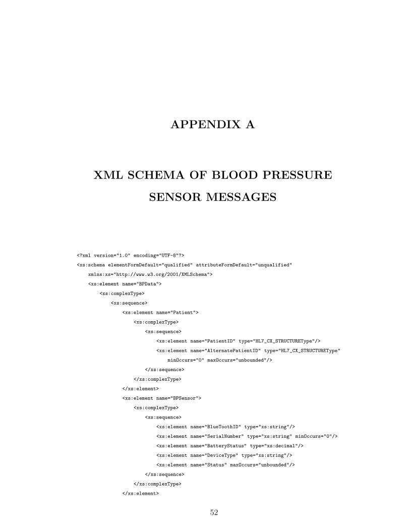
APPENDIX A
XML SCHEMA OF BLOOD PRESSURE
SENSOR MESSAGES
<?xml version="1.0" encoding="UTF-8"?>
<xs:schema elementFormDefault="qualified" attributeFormDefault="unqualified"
xmlns:xs="http://www.w3.org/2001/XMLSchema">
<xs:element name="BPData">
<xs:complexType>
<xs:sequence>
<xs:element name="Patient">
<xs:complexType>
<xs:sequence>
<xs:element name="PatientID" type="HL7_CX_STRUCTUREType"/>
<xs:element name="AlternatePatientID" type="HL7_CX_STRUCTUREType"
minOccurs="0" maxOccurs="unbounded"/>
</xs:sequence>
</xs:complexType>
</xs:element>
<xs:element name="BPSensor">
<xs:complexType>
<xs:sequence>
<xs:element name="BlueToothID" type="xs:string"/>
<xs:element name="SerialNumber" type="xs:string" minOccurs="0"/>
<xs:element name="BatteryStatus" type="xs:decimal"/>
<xs:element name="DeviceType" type="xs:string"/>
<xs:element name="Status" maxOccurs="unbounded"/>
</xs:sequence>
</xs:complexType>
</xs:element>
52

<xs:element name="BPMeasurement" maxOccurs="unbounded">
<xs:complexType>
<xs:sequence>
<xs:element name="Valid" type="xs:boolean"/>
<xs:element name="TimeOfMeasurement" type="xs:dateTime"/>
<xs:element name="TimeOfTransmission" type="xs:dateTime"/>
<xs:element name="SystolicPressure" type="xs:int"/>
<xs:element name="DiastolicPressure" type="xs:int"/>
<xs:element name="PulseRatePerMinute" type="xs:int"/>
<xs:element name="MeanArterialPressure" type="xs:int"/>
</xs:sequence>
</xs:complexType>
</xs:element>
</xs:sequence>
<xs:attribute name="SchemaVersion" type="xs:decimal" fixed="1.0"/>
</xs:complexType>
</xs:element>
<xs:element name="HL7_CX_STRUCTURE" type="HL7_CX_STRUCTUREType"/>
<xs:element name="HL7_HD_STRUCTURE" type="HL7_HD_STRUCTUREType"/>
<xs:complexType name="HL7_HD_STRUCTUREType">
<xs:sequence>
<xs:element name="NameSpaceID" type="xs:string"/>
<xs:element name="UniversalID" type="xs:string"/>
<xs:element name="UniversalIDType" type="xs:string"/>
</xs:sequence>
</xs:complexType>
<xs:element name="HL7_CWE_STRUCTURE" type="HL7_CWE_STRUCTUREType"/>
<xs:complexType name="HL7_CWE_STRUCTUREType">
<xs:sequence>
<xs:element name="Identifier" type="xs:string"/>
<xs:element name="Text" type="xs:string"/>
<xs:element name="NameOfCodingSystem" type="xs:string"/>
<xs:element name="AlternateIdentifier" type="xs:string"/>
<xs:element name="AlternateText" type="xs:string"/>
<xs:element name="NameOfAlternateCodingSystem" type="xs:string"/>
<xs:element name="CodingSystemVersionID" type="xs:string"/>
<xs:element name="AlternateCodingSystemVersionID" type="xs:string"/>
<xs:element name="OriginalText" type="xs:string"/>
</xs:sequence>
</xs:complexType>
<xs:complexType name="HL7_CX_STRUCTUREType">
<xs:sequence>
<xs:element name="IDNumber" type="xs:string"/>
<xs:element name="CheckDigit" type="xs:string" minOccurs="0"/>
<xs:element name="CheckDigitScheme" type="xs:string" minOccurs="0"/>
<xs:element name="AssigningAuthority" type="HL7_HD_STRUCTUREType"/>
53

<xs:element name="IdentifierTypeCode" type="xs:string" minOccurs="0"/>
<xs:element name="AssigningFacility" type="HL7_HD_STRUCTUREType" minOccurs="0"/>
<xs:element name="EffectiveDate" type="xs:dateTime" minOccurs="0"/>
<xs:element name="ExpirationDate" type="xs:dateTime" minOccurs="0"/>
<xs:element name="AssigningJurisdiction" type="HL7_CWE_STRUCTUREType" minOccurs="0"/>
<xs:element name="AssigningAgencyOrDepartment" type="HL7_CWE_STRUCTUREType" minOccurs="0"/>
</xs:sequence>
</xs:complexType>
</xs:schema>
54

APPENDIX B
XML MESSAGE OF A BLOOD PRESSURE
SENSOR OBSERVATION
<?xml version="1.0" encoding="UTF-8"?>
<BPData>
<Patient>
<PatientID>
<IDNumber>1248327</IDNumber>
<AssigningAuthority>
<NameSpaceID>METU</NameSpaceID>
<UniversalID>SAPHIRE</UniversalID>
</AssigningAuthority>
</PatientID>
</Patient>
<BPSensor>
<BlueToothID>blueID</BlueToothID>
<SerialNumber>Serial1.2.3</SerialNumber>
<BatteryStatus>23.2</BatteryStatus>
<DeviceType>23.2</DeviceType>
<Status>statusOK</Status>
</BPSensor>
<BPMeasurement>
<Valid>true</Valid>
<TimeOfMeasurement>2006-11-07T11:18:32</TimeOfMeasurement>
<TimeOfTransmission>2006-11-07T11:19:01</TimeOfTransmission>
<SystolicPressure>26</SystolicPressure>
<DiastolicPressure>84</DiastolicPressure>
<PulseRatePerMinute>5</PulseRatePerMinute>
<MeanArterialPressure>54</MeanArterialPressure>
55

</BPMeasurement>
</BPData>
56
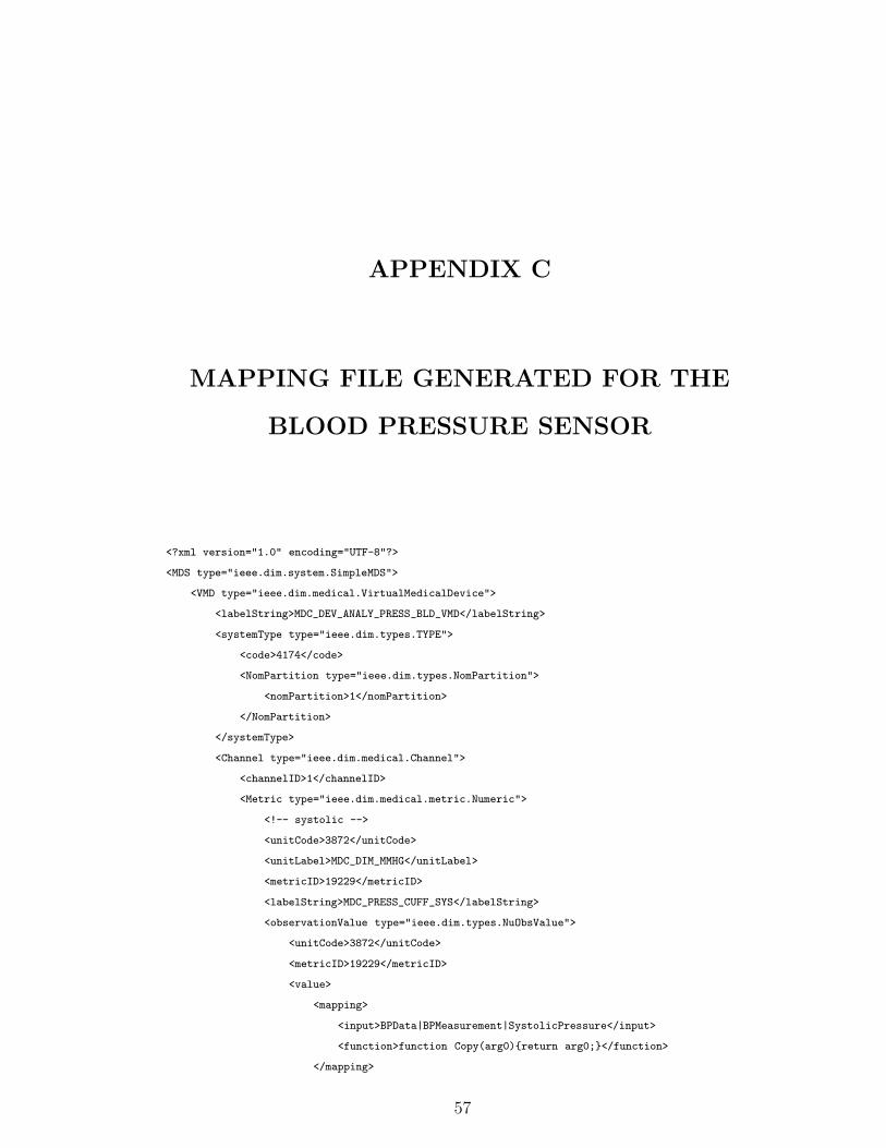
APPENDIX C
MAPPING FILE GENERATED FOR THE
BLOOD PRESSURE SENSOR
<?xml version="1.0" encoding="UTF-8"?>
<MDS type="ieee.dim.system.SimpleMDS">
<VMD type="ieee.dim.medical.VirtualMedicalDevice">
<labelString>MDC_DEV_ANALY_PRESS_BLD_VMD</labelString>
<systemType type="ieee.dim.types.TYPE">
<code>4174</code>
<NomPartition type="ieee.dim.types.NomPartition">
<nomPartition>1</nomPartition>
</NomPartition>
</systemType>
<Channel type="ieee.dim.medical.Channel">
<channelID>1</channelID>
<Metric type="ieee.dim.medical.metric.Numeric">
<!-- systolic -->
<unitCode>3872</unitCode>
<unitLabel>MDC_DIM_MMHG</unitLabel>
<metricID>19229</metricID>
<labelString>MDC_PRESS_CUFF_SYS</labelString>
<observationValue type="ieee.dim.types.NuObsValue">
<unitCode>3872</unitCode>
<metricID>19229</metricID>
<value>
<mapping>
<input>BPData|BPMeasurement|SystolicPressure</input>
<function>function Copy(arg0){return arg0;}</function>
</mapping>
57

</value>
<state type="ieee.dim.types.MeasurementStatus">
<status>
<mapping>
<input>BPData|BPMeasurement|Valid</input>
<function>function isValid(arg0){ if(arg0==true)
return 8; else return 0;}</function>
</mapping>
</status>
</state>
</observationValue>
<absoluteRange type="ieee.dim.types.AbsoluteRange">
<lowerValue>0</lowerValue>
<upperValue>100</upperValue>
</absoluteRange>
<bodySiteLabel>MDC_UPEXT_ARM_UPPER_L</bodySiteLabel>
<bodySiteCode>1781</bodySiteCode>
<metricPartition>
<NomPartition type="ieee.dim.types.NomPartition">
<nomPartition>2</nomPartition>
</NomPartition>
</metricPartition>
<absoluteTime type="ieee.dim.types.AbsoluteTime">
<!--CCYY-MM-DDThh:mm:ss-->
<hour>
<mapping>
<input>BPData|BPMeasurement|TimeOfMeasurement</input>
<function>function Copy(arg0){return
arg0.substring(11,13);}</function>
</mapping>
</hour>
<day>
<mapping>
<input>BPData|BPMeasurement|TimeOfMeasurement</input>
<function>function Copy(arg0){return
arg0.substring(8,10);}</function>
</mapping>
</day>
<second>
<mapping>
<input>BPData|BPMeasurement|TimeOfMeasurement</input>
<function>function Copy(arg0){return
arg0.substring(17,19);}</function>
</mapping>
</second>
<year>
58

<mapping>
<input>BPData|BPMeasurement|TimeOfMeasurement</input>
<function>function Copy(arg0){return
arg0.substring(0,3);}</function>
</mapping>
</year>
<month>
<mapping>
<input>BPData|BPMeasurement|TimeOfMeasurement</input>
<function>function Copy(arg0){return
arg0.substring(5,7);}</function>
</mapping>
</month>
<minute>
<mapping>
<input>BPData|BPMeasurement|TimeOfMeasurement</input>
<function>function Copy(arg0){return
arg0.substring(14,16);}</function>
</mapping>
</minute>
<century>21</century>
</absoluteTime>
</Metric>
<Metric type="ieee.dim.medical.metric.Numeric"><!-- diastolic -->
<unitCode>3872</unitCode>
<unitLabel>MDC_DIM_MMHG</unitLabel>
<metricID>19230</metricID>
<labelString>MDC_PRESS_CUFF_DIA</labelString>
<observationValue type="ieee.dim.types.NuObsValue">
<unitCode>3872</unitCode>
<metricID>19230</metricID>
<value>
<mapping>
<input>BPData|BPMeasurement|DiastolicPressure</input>
<function>function Copy(arg0){return arg0;}</function>
</mapping>
</value>
<state type="ieee.dim.types.MeasurementStatus">
<status>
<mapping>
<input>BPData|BPMeasurement|Valid</input>
<function>function isValid(arg0){if(arg0==true) return 8;
else return 0;}</function>
</mapping>
</status>
</state>
59
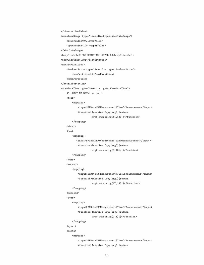
</observationValue>
<absoluteRange type="ieee.dim.types.AbsoluteRange">
<lowerValue>0</lowerValue>
<upperValue>100</upperValue>
</absoluteRange>
<bodySiteLabel>MDC_UPEXT_ARM_UPPER_L</bodySiteLabel>
<bodySiteCode>1781</bodySiteCode>
<metricPartition>
<NomPartition type="ieee.dim.types.NomPartition">
<nomPartition>2</nomPartition>
</NomPartition>
</metricPartition>
<absoluteTime type="ieee.dim.types.AbsoluteTime">
<!--CCYY-MM-DDThh:mm:ss-->
<hour>
<mapping>
<input>BPData|BPMeasurement|TimeOfMeasurement</input>
<function>function Copy(arg0){return
arg0.substring(11,13);}</function>
</mapping>
</hour>
<day>
<mapping>
<input>BPData|BPMeasurement|TimeOfMeasurement</input>
<function>function Copy(arg0){return
arg0.substring(8,10);}</function>
</mapping>
</day>
<second>
<mapping>
<input>BPData|BPMeasurement|TimeOfMeasurement</input>
<function>function Copy(arg0){return
arg0.substring(17,19);}</function>
</mapping>
</second>
<year>
<mapping>
<input>BPData|BPMeasurement|TimeOfMeasurement</input>
<function>function Copy(arg0){return
arg0.substring(0,3);}</function>
</mapping>
</year>
<month>
<mapping>
<input>BPData|BPMeasurement|TimeOfMeasurement</input>
<function>function Copy(arg0){return
60

arg0.substring(5,7);}</function>
</mapping>
</month>
<minute>
<mapping>
<input>BPData|BPMeasurement|TimeOfMeasurement</input>
<function>function Copy(arg0){return
arg0.substring(14,16);}</function>
</mapping>
</minute>
<century>21</century>
</absoluteTime>
</Metric>
<Metric type="ieee.dim.medical.metric.Numeric"><!-- MeanArterialPressure -->
<unitCode>3872</unitCode>
<unitLabel>MDC_DIM_MMHG</unitLabel>
<metricID>19231</metricID>
<labelString>MDC_PRESS_CUFF_MEAN</labelString>
<observationValue type="ieee.dim.types.NuObsValue">
<unitCode>3872</unitCode>
<metricID>19231</metricID>
<value>
<mapping>
<input>BPData|BPMeasurement|MeanArterialPressure</input>
<function>function Copy(arg0){return arg0;}</function>
</mapping>
</value>
<state type="ieee.dim.types.MeasurementStatus">
<status>
<mapping>
<input>BPData|BPMeasurement|Valid</input>
<function>function isValid(arg0){ if(arg0==true)
return 8; else return 0;}</function>
</mapping>
</status>
</state>
</observationValue>
<absoluteRange type="ieee.dim.types.AbsoluteRange">
<lowerValue>0</lowerValue>
<upperValue>100</upperValue>
</absoluteRange>
<bodySiteLabel>MDC_UPEXT_ARM_UPPER_L</bodySiteLabel>
<bodySiteCode>1781</bodySiteCode>
<metricPartition>
<NomPartition type="ieee.dim.types.NomPartition">
<nomPartition>2</nomPartition>
61
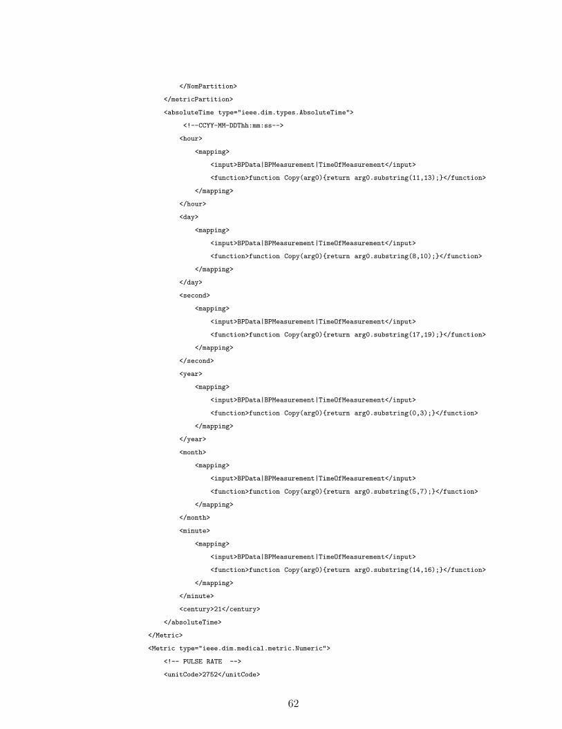
</NomPartition>
</metricPartition>
<absoluteTime type="ieee.dim.types.AbsoluteTime">
<!--CCYY-MM-DDThh:mm:ss-->
<hour>
<mapping>
<input>BPData|BPMeasurement|TimeOfMeasurement</input>
<function>function Copy(arg0){return arg0.substring(11,13);}</function>
</mapping>
</hour>
<day>
<mapping>
<input>BPData|BPMeasurement|TimeOfMeasurement</input>
<function>function Copy(arg0){return arg0.substring(8,10);}</function>
</mapping>
</day>
<second>
<mapping>
<input>BPData|BPMeasurement|TimeOfMeasurement</input>
<function>function Copy(arg0){return arg0.substring(17,19);}</function>
</mapping>
</second>
<year>
<mapping>
<input>BPData|BPMeasurement|TimeOfMeasurement</input>
<function>function Copy(arg0){return arg0.substring(0,3);}</function>
</mapping>
</year>
<month>
<mapping>
<input>BPData|BPMeasurement|TimeOfMeasurement</input>
<function>function Copy(arg0){return arg0.substring(5,7);}</function>
</mapping>
</month>
<minute>
<mapping>
<input>BPData|BPMeasurement|TimeOfMeasurement</input>
<function>function Copy(arg0){return arg0.substring(14,16);}</function>
</mapping>
</minute>
<century>21</century>
</absoluteTime>
</Metric>
<Metric type="ieee.dim.medical.metric.Numeric">
<!-- PULSE RATE -->
<unitCode>2752</unitCode>
62

<unitLabel>MDC_DIM_PULS_PER_MIN</unitLabel>
<metricID>18442</metricID>
<labelString>MDC_PULS_RATE</labelString>
<absoluteTime type="ieee.dim.types.AbsoluteTime">
<!--CCYY-MM-DDThh:mm:ss-->
<hour>
<mapping>
<input>BPData|BPMeasurement|TimeOfMeasurement</input>
<function>function Copy(arg0){return arg0.substring(11,13);}</function>
</mapping>
</hour>
<day>
<mapping>
<input>BPData|BPMeasurement|TimeOfMeasurement</input>
<function>function Copy(arg0){return arg0.substring(8,10);}</function>
</mapping>
</day>
<second>
<mapping>
<input>BPData|BPMeasurement|TimeOfMeasurement</input>
<function>function Copy(arg0){return arg0.substring(17,19);}</function>
</mapping>
</second>
<year>
<mapping>
<input>BPData|BPMeasurement|TimeOfMeasurement</input>
<function>function Copy(arg0){return arg0.substring(0,3);}</function>
</mapping>
</year>
<month>
<mapping>
<input>BPData|BPMeasurement|TimeOfMeasurement</input>
<function>function Copy(arg0){return arg0.substring(5,7);}</function>
</mapping>
</month>
<minute>
<mapping>
<input>BPData|BPMeasurement|TimeOfMeasurement</input>
<function>function Copy(arg0){return arg0.substring(14,16);}</function>
</mapping>
</minute>
<century>21</century>
</absoluteTime>
<observationValue type="ieee.dim.types.NuObsValue">
<unitCode>2752</unitCode>
<metricID>18442</metricID>
63

<value>
<mapping>
<input>BPData|BPMeasurement|PulseRatePerMinute</input>
<function>function Copy(arg0){return arg0;}</function>
</mapping>
</value>
<state type="ieee.dim.types.MeasurementStatus">
<status>
<mapping>
<input>BPData|BPMeasurement|PulseRatePerMinute</input>
<function>function isValid(arg0){ if(arg0==true)
return 8; else return 0;}</function>
</mapping>
</status>
</state>
</observationValue>
<absoluteRange type="ieee.dim.types.AbsoluteRange">
<lowerValue>0</lowerValue>
<upperValue>250</upperValue>
</absoluteRange>
<bodySiteLabel>MDC_UPEXT_ARM_UPPER_L</bodySiteLabel>
<bodySiteCode>1781</bodySiteCode>
<metricPartition>
<NomPartition type="ieee.dim.types.NomPartition">
<nomPartition>2</nomPartition>
</NomPartition>
</metricPartition>
</Metric>
</Channel>
</VMD>
<Patient type="ieee.dim.patient.PatientDemographics">
<patientID>
<mapping>
<input>BPData|Patient|PatientID|IDNumber</input>
<function>function Copy(arg0){return arg0;}</function>
</mapping>
</patientID>
</Patient>
</MDS>
64

APPENDIX D
UNSOLICITED OBSERVATION MESSAGE
TRANSFORMED FOR THE BLOOD
PRESSURE SENSOR OBSERVATION
MSH|^~\&|SRDCORIGateway^AABB12319231DDCA^EUI-64||UUID||20061107||ORU^R01^ORU_R01|MSG73910|P|2.5|
||NE|NE|TR||||IHE PCD ORU-R01 2006^HL7^2.16.840.1.113883.9.n.m^HL7
PID|||1248327^^^METU^SAPHIRE||null^null|||A
OBR|1|OBR73910^SRDCORIGateway^AABB12319231DDCA^EUI-64|Filler73910^SRDCORIGateway^AABB12319231DDCA^
EUI-64|69710^MDC_DEV_ANALY_PRESS_BLD_VMD^MDC|||20061107111832
OBX|1|NM|150301^MDC_PRESS_CUFF_SYS^MDC|1.1.1.1|26.0|266016^MDC_DIM_MMHG^MDC|10.0-78.0||||W|||
|20061107111832||||460533^MDC_UPEXT_ARM_UPPER_L^MDC
OBX|2|NM|150302^MDC_PRESS_CUFF_DIA^MDC|1.1.1.2|84.0|266016^MDC_DIM_MMHG^MDC|20.0-98.0||||W|||
|20061107111832||||460533^MDC_UPEXT_ARM_UPPER_L^MDC
OBX|3|NM|150303^MDC_PRESS_CUFF_MEAN^MDC|1.1.1.3|54.0|266016^MDC_DIM_MMHG^MDC|20.0-60.0||||W|||
|20061107111832||||460533^MDC_UPEXT_ARM_UPPER_L^MDC
OBX|4|NM|149514^MDC_PULS_RATE^MDC|1.1.1.4|5.0|264896^MDC_DIM_PULS_PER_MIN^MDC|0.0-250.0||||W|||
|20061107111832||||460533^MDC_UPEXT_ARM_UPPER_L^MDC
65

APPENDIX E
GLIF MESSAGE TRANSFORMED FOR THE
BLOOD PRESSURE SENSOR
OBSERVATION
<?xml version="1.0" encoding="UTF-8"?>
<Data>
<Patient_Data>
<Patient_ID>
<Internal_ID>1248327</Internal_ID>
</Patient_ID>
<Name>Alper</Name>
<Surname>Okcan</Surname>
<Title>Mr</Title>
<Gender>M</Gender>
<Birth_Information>
<Birth_Date>1982-03-31</Birth_Date>
</Birth_Information>
</Patient_Data>
<Observation>
<Id_OB>150303^MDC_PRESS_CUFF_MEAN</Id_OB>
<Severity_OB>0</Severity_OB>
<Text_Value>54.0</Text_Value>
</Observation>
<Observation>
<Id_OB>150301^MDC_PRESS_CUFF_SYS</Id_OB>
<Severity_OB>0</Severity_OB>
<Text_Value>26.0</Text_Value>
</Observation>
66

<Observation>
<Id_OB>150302^MDC_PRESS_CUFF_DIA</Id_OB>
<Severity_OB>0</Severity_OB>
<Text_Value>84.00</Text_Value>
</Observation>
<Observation>
<Id_OB>149514^MDC_PULS_RATE</Id_OB>
<Severity_OB>0</Severity_OB>
<Text_Value>5</Text_Value>
</Observation>
</Data>
67

APPENDIX F
XML SCHEMA OF PULSE OXIMETER
MESSAGES
<?xml version="1.0" encoding="UTF-8"?>
<xs:schema elementFormDefault="qualified" attributeFormDefault="unqualified"
xmlns:xs="http://www.w3.org/2001/XMLSchema">
<xs:element name="SPO2Data">
<xs:complexType>
<xs:sequence>
<xs:element name="Patient">
<xs:complexType>
<xs:sequence>
<xs:element name="PatientID" type="HL7_CX_STRUCTUREType"/>
<xs:element name="AlternatePatientID" type="HL7_CX_STRUCTUREType"
minOccurs="0" maxOccurs="unbounded"/>
</xs:sequence>
</xs:complexType>
</xs:element>
<xs:element name="SPO2Sensor">
<xs:complexType>
<xs:sequence>
<xs:element name="BlueToothID" type="xs:string"/>
<xs:element name="SerialNumber" type="xs:string" minOccurs="0"/>
<xs:element name="BatteryStatus" type="xs:decimal"/>
<xs:element name="DeviceType" type="xs:string"/>
<xs:element name="Status" type="xs:string" maxOccurs="unbounded"/>
</xs:sequence>
</xs:complexType>
</xs:element>
68

<xs:element name="SPO2Measurement" maxOccurs="unbounded">
<xs:complexType>
<xs:sequence>
<xs:element name="Valid" type="xs:boolean"/>
<xs:element name="TimeOfMeasurement" type="xs:dateTime"/>
<xs:element name="TimeOfTransmission" type="xs:dateTime"/>
<xs:element name="SPO2" type="xs:int"/>
<xs:element name="PulseRatePerMinute" type="xs:int"/>
<xs:element name="Pleth" type="xs:int" minOccurs="0" maxOccurs="10"/>
<xs:element name="SignalQuality" type="xs:int"/>
<xs:element name="SignalAmplification" type="xs:int"/>
</xs:sequence>
</xs:complexType>
</xs:element>
</xs:sequence>
<xs:attribute name="SchemaVersion" type="xs:decimal" fixed="1.0"/>
</xs:complexType>
</xs:element>
<xs:element name="HL7_CX_STRUCTURE" type="HL7_CX_STRUCTUREType"/>
<xs:element name="HL7_HD_STRUCTURE" type="HL7_HD_STRUCTUREType"/>
<xs:complexType name="HL7_HD_STRUCTUREType">
<xs:sequence>
<xs:element name="NameSpaceID" type="xs:string"/>
<xs:element name="UniversalID" type="xs:string"/>
<xs:element name="UniversalIDType" type="xs:string"/>
</xs:sequence>
</xs:complexType>
<xs:element name="HL7_CWE_STRUCTURE" type="HL7_CWE_STRUCTUREType"/>
<xs:complexType name="HL7_CWE_STRUCTUREType">
<xs:sequence>
<xs:element name="Identifier" type="xs:string"/>
<xs:element name="Text" type="xs:string"/>
<xs:element name="NameOfCodingSystem" type="xs:string"/>
<xs:element name="AlternateIdentifier" type="xs:string"/>
<xs:element name="AlternateText" type="xs:string"/>
<xs:element name="NameOfAlternateCodingSystem" type="xs:string"/>
<xs:element name="CodingSystemVersionID" type="xs:string"/>
<xs:element name="AlternateCodingSystemVersionID" type="xs:string"/>
<xs:element name="OriginalText" type="xs:string"/>
</xs:sequence>
</xs:complexType>
<xs:complexType name="HL7_CX_STRUCTUREType">
<xs:sequence>
<xs:element name="IDNumber" type="xs:string"/>
<xs:element name="CheckDigit" type="xs:string" minOccurs="0"/>
<xs:element name="CheckDigitScheme" type="xs:string" minOccurs="0"/>
69

<xs:element name="AssigningAuthority" type="HL7_HD_STRUCTUREType"/>
<xs:element name="IdentifierTypeCode" type="xs:string" minOccurs="0"/>
<xs:element name="AssigningFacility" type="HL7_HD_STRUCTUREType" minOccurs="0"/>
<xs:element name="EffectiveDate" type="xs:dateTime" minOccurs="0"/>
<xs:element name="ExpirationDate" type="xs:dateTime" minOccurs="0"/>
<xs:element name="AssigningJurisdiction" type="HL7_CWE_STRUCTUREType" minOccurs="0"/>
<xs:element name="AssigningAgencyOrDepartment" type="HL7_CWE_STRUCTUREType" minOccurs="0"/>
</xs:sequence>
</xs:complexType>
</xs:schema>
70
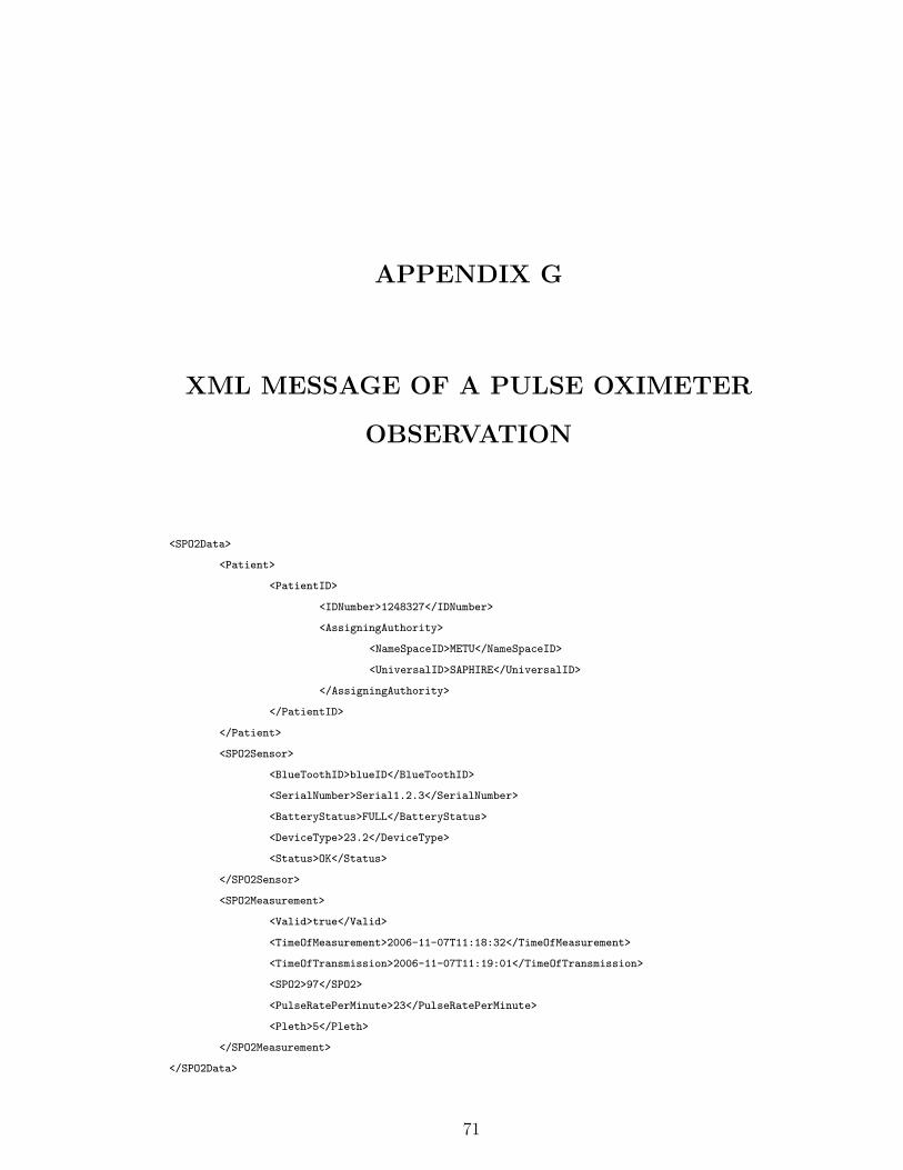
APPENDIX G
XML MESSAGE OF A PULSE OXIMETER
OBSERVATION
<SPO2Data>
<Patient>
<PatientID>
<IDNumber>1248327</IDNumber>
<AssigningAuthority>
<NameSpaceID>METU</NameSpaceID>
<UniversalID>SAPHIRE</UniversalID>
</AssigningAuthority>
</PatientID>
</Patient>
<SPO2Sensor>
<BlueToothID>blueID</BlueToothID>
<SerialNumber>Serial1.2.3</SerialNumber>
<BatteryStatus>FULL</BatteryStatus>
<DeviceType>23.2</DeviceType>
<Status>OK</Status>
</SPO2Sensor>
<SPO2Measurement>
<Valid>true</Valid>
<TimeOfMeasurement>2006-11-07T11:18:32</TimeOfMeasurement>
<TimeOfTransmission>2006-11-07T11:19:01</TimeOfTransmission>
<SPO2>97</SPO2>
<PulseRatePerMinute>23</PulseRatePerMinute>
<Pleth>5</Pleth>
</SPO2Measurement>
</SPO2Data>
71

APPENDIX H
MAPPING FILE GENERATED FOR THE
PULSE OXIMETER SENSOR
<MDS type="ieee.dim.system.SimpleMDS">
<VMD type="ieee.dim.medical.VirtualMedicalDevice">
<labelString>MDC_DEV_ANALY_SAT_O2_VMD</labelString>
<systemType type="ieee.dim.types.TYPE">
<code>4106</code>
<NomPartition type="ieee.dim.types.NomPartition">
<nomPartition>1</nomPartition>
</NomPartition>
</systemType>
<Channel type="ieee.dim.medical.Channel">
<channelID>1</channelID>
<Metric type="ieee.dim.medical.metric.Numeric">
<unitCode>544</unitCode>
<unitLabel>MDC_DIM_PERCENT</unitLabel>
<metricID>19384</metricID>
<labelString>MDC_PULS_OXIM_SAT_O2</labelString>
<absoluteTime type="ieee.dim.types.AbsoluteTime">
<!--CCYY-MM-DDThh:mm:ss-->
<hour>
<mapping>
<input>SPO2Data|SPO2Measurement|TimeOfMeasurement</input>
<function>function Copy(arg0){
return arg0.substring(11,13);}</function>
</mapping>
</hour>
<day>
72

<mapping>
<input>SPO2Data|SPO2Measurement|TimeOfMeasurement</input>
<function>function Copy(arg0){
return arg0.substring(8,10);}</function>
</mapping>
</day>
<second>
<mapping>
<input>SPO2Data|SPO2Measurement|TimeOfMeasurement</input>
<function>function Copy(arg0){
return arg0.substring(17,19);}</function>
</mapping>
</second>
<year>
<mapping>
<input>SPO2Data|SPO2Measurement|TimeOfMeasurement</input>
<function>function Copy(arg0){
return arg0.substring(0,3);}</function>
</mapping>
</year>
<month>
<mapping>
<input>SPO2Data|SPO2Measurement|TimeOfMeasurement</input>
<function>function Copy(arg0){
return arg0.substring(5,7);}</function>
</mapping>
</month>
<minute>
<mapping>
<input>SPO2Data|SPO2Measurement|TimeOfMeasurement</input>
<function>function Copy(arg0){
return arg0.substring(14,16);}</function>
</mapping>
</minute>
<century>21</century>
</absoluteTime>
<observationValue type="ieee.dim.types.NuObsValue">
<unitCode>544</unitCode>
<metricID>19384</metricID>
<value>
<mapping>
<input>SPO2Data|SPO2Measurement|SPO2</input>
<function>function Copy(arg0){return arg0;}</function>
</mapping>
</value>
<state type="ieee.dim.types.MeasurementStatus">
73

<status>
<mapping>
<input>SPO2Data|SPO2Measurement|Valid</input>
<function>function isValid(arg0){ if(arg0==true)
return 8; else return 0;}</function>
</mapping>
</status>
</state>
</observationValue>
<absoluteRange type="ieee.dim.types.AbsoluteRange">
<lowerValue>0</lowerValue>
<upperValue>100</upperValue>
</absoluteRange>
<bodySiteLabel>MDC_HEAD_EAR_R</bodySiteLabel>
<bodySiteCode>1522</bodySiteCode>
<metricPartition>
<NomPartition type="ieee.dim.types.NomPartition">
<nomPartition>2</nomPartition>
</NomPartition>
</metricPartition>
</Metric>
<Metric type="ieee.dim.medical.metric.Numeric"><!-- PULSE RATE -->
<unitCode>2752</unitCode>
<unitLabel>MDC_DIM_PULS_PER_MIN</unitLabel>
<metricID>18458</metricID>
<labelString>MDC_PULS_OXIM_PULS_RATE</labelString>
<absoluteTime type="ieee.dim.types.AbsoluteTime">
<!--CCYY-MM-DDThh:mm:ss-->
<hour>
<mapping>
<input>SPO2Data|SPO2Measurement|TimeOfMeasurement</input>
<function>function Copy(arg0){
return arg0.substring(11,13);}</function>
</mapping>
</hour>
<day>
<mapping>
<input>SPO2Data|SPO2Measurement|TimeOfMeasurement</input>
<function>function Copy(arg0){
return arg0.substring(8,10);}</function>
</mapping>
</day>
<second>
<mapping>
<input>SPO2Data|SPO2Measurement|TimeOfMeasurement</input>
<function>function Copy(arg0){
74

return arg0.substring(17,19);}</function>
</mapping>
</second>
<year>
<mapping>
<input>SPO2Data|SPO2Measurement|TimeOfMeasurement</input>
<function>function Copy(arg0){
return arg0.substring(0,3);}</function>
</mapping>
</year>
<month>
<mapping>
<input>SPO2Data|SPO2Measurement|TimeOfMeasurement</input>
<function>function Copy(arg0){
return arg0.substring(5,7);}</function>
</mapping>
</month>
<minute>
<mapping>
<input>SPO2Data|SPO2Measurement|TimeOfMeasurement</input>
<function>function Copy(arg0){
return arg0.substring(14,16);}</function>
</mapping>
</minute>
<century>21</century>
</absoluteTime>
<observationValue type="ieee.dim.types.NuObsValue">
<unitCode>2752</unitCode>
<metricID>18458</metricID>
<value>
<mapping>
<input>SPO2Data|SPO2Measurement|PulseRatePerMinute</input>
<function>function Copy(arg0){return arg0;}</function>
</mapping>
</value>
<state type="ieee.dim.types.MeasurementStatus">
<status>
<mapping>
<input>SPO2Data|SPO2Measurement|Valid</input>
<function>function isValid(arg0){
if(arg0==true) return 8; else return 0;}</function>
</mapping>
</status>
</state>
</observationValue>
<absoluteRange type="ieee.dim.types.AbsoluteRange">
75

<lowerValue>0</lowerValue>
<upperValue>250</upperValue>
</absoluteRange>
<bodySiteLabel>MDC_HEAD_EAR_R</bodySiteLabel>
<bodySiteCode>1522</bodySiteCode>
<metricPartition>
<NomPartition type="ieee.dim.types.NomPartition">
<nomPartition>2</nomPartition>
</NomPartition>
</metricPartition>
</Metric>
<Metric type="ieee.dim.medical.metric.Numeric"><!-- PLETH -->
<unitCode>2752</unitCode>
<unitLabel>MDC_DIM_PULS_PER_MIN</unitLabel>
<metricID>19380</metricID>
<labelString>MDC_PULS_OXIM_PLETH</labelString>
<absoluteTime type="ieee.dim.types.AbsoluteTime">
<!--CCYY-MM-DDThh:mm:ss-->
<hour>
<mapping>
<input>SPO2Data|SPO2Measurement|TimeOfMeasurement</input>
<function>function Copy(arg0){
return arg0.substring(11,13);}</function>
</mapping>
</hour>
<day>
<mapping>
<input>SPO2Data|SPO2Measurement|TimeOfMeasurement</input>
<function>function Copy(arg0){
return arg0.substring(8,10);}</function>
</mapping>
</day>
<second>
<mapping>
<input>SPO2Data|SPO2Measurement|TimeOfMeasurement</input>
<function>function Copy(arg0){
return arg0.substring(17,19);}</function>
</mapping>
</second>
<year>
<mapping>
<input>SPO2Data|SPO2Measurement|TimeOfMeasurement</input>
<function>function Copy(arg0){
return arg0.substring(0,3);}</function>
</mapping>
</year>
76

<month>
<mapping>
<input>SPO2Data|SPO2Measurement|TimeOfMeasurement</input>
<function>function Copy(arg0){
return arg0.substring(5,7);}</function>
</mapping>
</month>
<minute>
<mapping>
<input>SPO2Data|SPO2Measurement|TimeOfMeasurement</input>
<function>function Copy(arg0){
return arg0.substring(14,16);}</function>
</mapping>
</minute>
<century>21</century>
</absoluteTime>
<observationValue type="ieee.dim.types.NuObsValue">
<unitCode>2752</unitCode>
<metricID>19380</metricID>
<value>
<mapping>
<input>SPO2Data|SPO2Measurement|Pleth</input>
<function>function Copy(arg0){return arg0;}</function>
</mapping>
</value>
<state type="ieee.dim.types.MeasurementStatus">
<status>
<mapping>
<input>SPO2Data|SPO2Measurement|Valid</input>
<function>function isValid(arg0){
if(arg0==true) return 8; else return 0;}</function>
</mapping>
</status>
</state>
</observationValue>
<absoluteRange type="ieee.dim.types.AbsoluteRange">
<lowerValue>0</lowerValue>
<upperValue>125</upperValue>
</absoluteRange>
<bodySiteLabel>MDC_HEAD_EAR_R</bodySiteLabel>
<bodySiteCode>1522</bodySiteCode>
<metricPartition>
<NomPartition type="ieee.dim.types.NomPartition">
<nomPartition>2</nomPartition>
</NomPartition>
</metricPartition>
77

</Metric>
</Channel>
</VMD>
<Patient type="ieee.dim.patient.PatientDemographics">
<patientID>
<mapping>
<input>SPO2Data|Patient|PatientID|IDNumber</input>
<function>function Copy(arg0){return arg0;}</function>
</mapping>
</patientID>
<!--patientTitle>Mr</patientTitle-->
<!--DateOfBirth type="ieee.dim.types.Date">
<day>31</day>
<year>1982</year>
<month>3</month>
<century>20</century>
</DateOfBirth-->
<!--patientName>alper</patientName-->
<!--patientFamilyName>okcan</patientFamilyName-->
<!--PatientSex type="ieee.dim.types.PatientSex">
<patientSex>1</patientSex>
</PatientSex-->
</Patient>
</MDS>
78

APPENDIX I
UNSOLICITED OBSERVATION MESSAGE
TRANSFORMED FOR THE PULSE
OXIMETER SENSOR OBSERVATION
MSH|^~\&|SRDCORIGateway^AABB12319231DDCA^EUI-64||null^null^UUID||20061107||ORU^R01^ORU_R01|
MSG73354|P|2.5|||NE|NE|TR||||IHE PCD ORU-R01 2006^HL7^2.16.840.1.113883.9.n.m^HL7
PID|||1248327^^^METU^SAPHIRE||null^null|||A
OBR|1|OBR73354^SRDCORIGateway^AABB12319231DDCA^EUI-64|Filler73354^SRDCORIGateway^
AABB12319231DDCA^EUI-64|69642^MDC_DEV_ANALY_SAT_O2_VMD^MDC|||2001107111832
OBX|1|NM|150456^MDC_PULS_OXIM_SAT_O2^MDC|1.1.1.1|97.0|262688^MDC_DIM_PERCENT^MDC|0.0-100.0|
|||W||||2001107111832||||460274^MDC_HEAD_EAR_R^MDC
OBX|2|NM|149530^MDC_PULS_OXIM_PULS_RATE^MDC|1.1.1.2|23.0|264896^MDC_DIM_PULS_PER_MIN^MDC|
0.0-250.0||||W||||2001107111832||||460274^MDC_HEAD_EAR_R^MDC
OBX|3|NM|150452^MDC_PULS_OXIM_PLETH^MDC|1.1.1.3|5.0|264896^MDC_DIM_PULS_PER_MIN^MDC|
0.0-125.0||||W||||2001107111832||||460274^MDC_HEAD_EAR_R^MDC
79

APPENDIX J
GLIF MESSAGE TRANSFORMED FOR THE
PULSE OXIMETER SENSOR
OBSERVATION
<?xml version="1.0" encoding="UTF-8"?>
<Data>
<Patient_Data>
<Patient_ID>
<Internal_ID>1248327</Internal_ID>
</Patient_ID>
<Name>Alper</Name>
<Surname>Okcan</Surname>
<Title>Mr</Title>
<Gender>M</Gender>
<Birth_Information>
<Birth_Date>1982-03-31</Birth_Date>
</Birth_Information>
</Patient_Data>
<Observation>
<Id_OB>150456^MDC_PULS_OXIM_SAT_O2</Id_OB>
<Severity_OB>0</Severity_OB>
<Text_Value>97.0</Text_Value>
</Observation>
<Observation>
<Id_OB>149530^MDC_PULS_OXIM_PULS_RATE</Id_OB>
<Severity_OB>0</Severity_OB>
<Text_Value>23.0</Text_Value>
</Observation>
80

<Observation>
<Id_OB>150452^MDC_PULS_OXIM_PLETH</Id_OB>
<Severity_OB>0</Severity_OB>
<Text_Value>5.00</Text_Value>
</Observation>
<Observation>
<Id_OB>149514^MDC_PULS_RATE</Id_OB>
<Severity_OB>0</Severity_OB>
<Text_Value>5</Text_Value>
</Observation>
</Data>
81