arr estado solido
TRANSCRIPT
8122019 Arr Estado Solido
httpslidepdfcomreaderfullarr-estado-solido 140
8122019 Arr Estado Solido
httpslidepdfcomreaderfullarr-estado-solido 240
Related catalogs Contents
Low-Voltage Controls andDistributionSIRIUS middot SENTRON middot SIVACONOrder No
Catalog
E86060-K1002-A101-A5-7600Technical InformationE86060-T1002-A101-A5-7600
LV 1
LV 1 T
Systems middot Controls Contactors and contactor assem-blies solid-state switching devices middot Protection equip-ment middot Load feeders motor starters and soft starters middot Monitoring and control devices middot Detecting devices middot Commanding and signaling devices middot Transformers middot Power supplies middot ALPHA FIX terminal blocks middot Planning
and configuration with SIRIUS middot SIVACON busway andcubicle systems middot SENTRON switching and protectiondevices for power distribution Air circuit-breakersmolded case circuit-breakers switch disconnectors middot Planning design and management with SIMARIS middot BETA modular installation devices
Industrial CommunicationIndustrial Communicationfor Automation and Drives
Order NoE86060-K6710-A101-B5-7600
IK PI PROFINETIndustrial Ethernet middot Industrial MobileCommunicaton middot PROFIBUS to IEC 61158EN 50170 middot SIMATIC ET 200 distributed IOs middot AS-Interface toEN 50295IEC 61158 middot Remote operation with SINAUTST7 middot Routers middot ECOFAST system
SICUBE
System Cubicles and CubicleAir-Conditioning
Order NoE86060-K1920-A101-A3-7600
LV 50 System Cubicles middot Cubicle Modifications middot Cubicle
Expansion middot Accessories middot Special Cubicles middot CubicleSo-lutions in Practice middot Cubicle Air-Conditioning middot SpecialColors
SIDACReactors and Filters
Order NoE86060-K2803-A101-A3-7600
LV 60 Commutating reactors for converters middot Mains reactors forfrequency converters middot Iron-core output reactors middot Ferrite output reactors middot Iron-core smoothing reactors middot Smoothing air-core reactors middot Filter reactors middot Applica-tion-specific reactors middot Radio interference suppressionfilters middot dvdt filters middot Sinewave filters
SIVACON 8PSBusway systems
CD BD01 BD2 to 1250 AOrder NoE86060-K1870-A101-A2-7600
LV 70 Busway systems Overview middot CD system (25 A to 40 A) middot BD01 system (40 A to 160 A) middot BD2 system (160 A to
1250 A)
Automation amp DrivesThe AampD Offline Mall
Order NoE86060-D4001-A110-C4-7600DVDE86060-D4001-A510-C4-7600
CA 01 All Automation and Drives productsincluding those in the catalogs listed above
AampD MallInternethttpwwwsiemenscom
automationmall
All Automation and Drives productsincluding those in the catalogs listed above
Catalog PDFInternethttpwwwautomationsiemenscomcd
All catalogs for Low-Voltage Controls can bedownloaded as pdf files
Registered trademarks Technical Assistance
All product designations may be registered trademarksor product names of Siemens AG or other supplyingcompanies Third parties using these trademarks orproduct names for their own purposes may infringeupon the rights of the trademark owners
Further information about low-voltage controls isavailable on the Internet at
httpwwwsiemenscomlowvoltage
Expert technical assistancefor Low-Voltage Controls andElectrical Installations
Tel +49 (9 11) 8 95-59 00
Fax +49 (9 11) 8 95-59 07E-Mail technical-assistancesiemenscom
LV1_U2_Bosch-Druckfm Seite 2 Dienstag 4 Juli 2006 1113 11
8122019 Arr Estado Solido
httpslidepdfcomreaderfullarr-estado-solido 340
InvalidCatalog LV 1 News middot April 2006Chapter 6 Load Feeders MotorStarters and Soft StartersSection 3RW44 Soft Startersfor High-Feature Applications
copy Siemens AG 2006
The products and
systems listed in this
catalog are distributed
manufactured using a
certified quality
management system
which complies with
EN ISO 9001
(Certificate Register
Nos can be found in
the appendix)The certificates are
recognized in all
IQ Net countries
1 Introduction
F
u
n
k
t
i
o
n
e
n
11 SupplyPower supplies
2 Systems 12 Connecting withALPHAALPHA FIX terminal blocks
3 ControlsContactors andcontactor assemblies
13 EngineeringSoftwarePlanning and configurationwith SIRIUS
4 Solid-state switching devices 14 Distributing withSIVACONSIVACON power distributio
boards busway andcubicle systems
5 ProtectingProtection equipment
15 Switching andProtecting withSENTRONAir circuit-breakers
6 StartingLoad feeders motor starters
and soft starters
16Molded case circuit-break
7 Monitoring andControlMonitoring andcontrol devices
17Switch disconnectors
8
DetectionDetecting devices
18
Engineering SoftwaPlanning design andmanagement with SIMARIS
9 Commanding andSignalingCommanding andsignaling devices
19 Protecting with BEBETA modular installationdevices
10 SupplyTransformers 20 Appendix
s
Low-Voltage Controlsand DistributionSIRIUS middot SENTRON middot SIVACON
Catalog LV 1 News
3RW44 SoftStarters middot 062006
8122019 Arr Estado Solido
httpslidepdfcomreaderfullarr-estado-solido 440
Niederspannungs-Schalttechnik
Delivery times (DT)
Preferred type
A 2 working days
B 1 week
C 3 weeks
D 6 week
X on request
Preferred types are available immediately fromstock ie are dispatched within 24 hours
Normal quantities of the products are usually deliv-red within the specified time following receipt ofyour order at our branch
In exceptional cases the actual delivery periodmay differ from that specified
The delivery periods apply up to the ramp at Siemens AG (products ready fordispatch) The transport times depend on the destination and type of shippingThe standard transport time for Germany is 1 day
The delivery times specified here represent the state of 062006 They are per-manently optimized Up-to-date information can be found atwwwsiemenscomautomationmall
Price units (PU)
The price unit defines the number of units sets ormeters to which the specified price and weight
apply
Packaging sizes (PS)
The packaging size defines the number eg ofunits sets or meters for outer packaging
Only the quantity defined by the packaging size ora multiple thereof can be ordered
For multi-unit packaging and recyclable packaging see Appendix of the LV 1catalog 2006
Price groups (PG)
Each product is assigned to a price group
Weight
The defined weight in kg refers to the price unit(PU)
Dimensions
All dimensions in mm
Explanations
LV1_News_00_03fm Seite 4 Dienstag 4 Juli 2006 1121 11
8122019 Arr Estado Solido
httpslidepdfcomreaderfullarr-estado-solido 540
3RW Soft Starters
62 General data
62 - Overview
63 3RW44 for High-Feature applications
63 - Overview63 - Application64 - Selection and ordering data
3RW Soft Starters
610 3RW44 for High-Feature applications610 - Function611 - Technical specifications625 - Characteristic curves626 - More information
629 Project planning aids
629 - Dimensional drawings631 - Schematics
Load Feeders MotorStarters and Soft Starters
Catalog
Technical Information
8122019 Arr Estado Solido
httpslidepdfcomreaderfullarr-estado-solido 640
3RW Soft Starters
General data
Overview
The advantages of the SIRIUS soft starters at a glancebull Soft starting and smooth ramp-down1)
bull Stepless startingbull Reduction of current peaksbull Avoidance of mains voltage fluctuations during startingbull Reduced load on the power supply network
bull Reduction of the mechanical load in the operating mechanismbull Considerable space savings and reduced wiring compared
with conventional startersbull Maintenance-free switchingbull Very easy handlingbull Fits perfectly in the SIRIUS modular system
Function is available
-- Function not available1) Only soft starting available for 3RW30 -1AA12 and 3RW312) Not available for 3RW30 033) Not possible in inside-delta circuit4) Trace function with Soft Starter ES5) For 3RW30 03 up to 230 V
6) Calculate soft starter and motor with size allowance where required
More information can be found on the Internet athttpwwwsiemenscomsoftstarter
SIRIUS 3RW3031 SIRIUS 3RW40 SIRIUS 3RW44Standard applications High-Feature applications
Rated current up to 40 degC A 3 100 134 432 29 1214
Rated operational voltage V 200 575 200 600 200 690
Motor rating at 400 Vbull Inline circuit kW 11 55 75 250 15 710bull Inside-delta circuit kW -- -- 22 1200
Temperature range degC -25 +60 -25 +60 0 +60
Soft startingramp-down 1)
Voltage ramp
Startingstopping voltage 40 100 40 100 20 100
Starting and ramp-down time s 0 20 0 20 1 360
Torque control -- --
Startingstopping torque -- -- 20 100
Torque limit -- -- 20 200
Ramp time s -- -- 1 360
Integral bypass contact system 2)
Intrinsic device protection --
Motor overload protection --
Thermistor motor protection -- --
Adjustable current limiting --
Inside-delta circuit -- --
Breakaway pulse -- --
Creep speed in both directions -- --
Pump ramp-down -- -- 6)
DC braking -- -- 3) 6)
Combined braking -- -- 3) 6)
Motor heating -- --
Communication -- -- with PROFIBUS DP (optional)
External display and operator module -- -- (optional)
Operating measured value display -- --
Error logbook -- --
Event list -- --
Slave pointer function -- --
Trace function -- -- 4)
Programmable control inputs and outputs -- --
Number of parameter sets 1 (2 with 3RW31) 1 3
Parameterization software (Soft Starter ES) -- --
Power semiconductors (thyristors) 2 controlled phases 2 controlled phases 3 controlled phases
Spring-loaded terminals (only 3RW30 03)
Screw terminals
ULCSA 5)
CE marking
Soft starting under heavy starting conditions -- -- 6)
Configuring support Win-Soft Starter the electronic selection slider ruler Technical Assistance ++49 911 895 5900
8122019 Arr Estado Solido
httpslidepdfcomreaderfullarr-estado-solido 740
3RW Soft Starters
3RW44for High-Feature applications
Overview
In addition to soft starting and soft ramp-down the solid-stateSIRIUS 3RW44 soft starters provide numerous functions for
higher-level requirements They cover a rating range up to710 kW (at 400 V) in the inline circuit and up to 1200 kW(at 400 V) in the inside-delta circuit
The SIRIUS 3RW44 soft starters are characterized by a compactdesign for space-saving and clearly arranged control cabinetlayouts For optimized motor starting and stopping the innova-tive SIRIUS 3RW44 soft starters are an attractive alternative withconsiderable savings potential compared to applications with afrequency converter The new torque control and adjustablecurrent limiting enable the High-Feature soft starters to be usedin nearly every conceivable task They guarantee the reliableavoidance of sudden torque applications and current peaksduring motor starting and stopping This creates savings poten-tial when calculating the size of the switchgear and when servic-ing the machinery installed Be it for inline circuits or inside-deltacircuits ndash the SIRIUS 3RW44 soft starter offers savings especiallyin terms of size and equipment costs
Combinations of various starting operating and ramp-downpossibilities ensure an optimum adaptation to the application-specific requirements Operating and commissioning can beperformed by means of the user-friendly keypad and a menu-prompted multi-line graphic display with background lightingThe optimized motor ramp-up and ramp-down can be effectedby means of just a few settings with a previously selectedlanguage Four-key operation and plain-text displays for eachmenu point guarantee full clarity at every moment of theparameterization and operation
Applicable standards
bull IEC 60947-4-2
bull ULCSA
Application
The SIRIUS 3RW44 solid-state soft starters are suitable for thetorque-controlled soft starting and smooth ramp-down as well as
braking of three-phase asynchronous motors
Application areas e g
bull Pumps
bull Ventilators
bull Compressors
bull Water transport
bull Conveying systems and lifts
bull Hydraulics
bull Machine tools
bull Mills
bull Saws
bull Breakers
bull Mixersbull Centrifuges
bull Industrial cooling and refrigerating systems
8122019 Arr Estado Solido
httpslidepdfcomreaderfullarr-estado-solido 840
3RW Soft Starters
3RW44for High-Feature applications
Selection and ordering data
1) 3RW44 2 3RW44 3 and 3RW44 4 soft starters with screw-typeterminals delivery time class (preferred type)
2) Control by way of the internal 24 V DC supply and direct control by meansof PLC possible
NoteSoft starter selection depends on the motors rated current
The 3RW44 solid-state soft starters are designed for normalstarting (class 10) (Inertia load of the overall operating mecha- nism JLoad lt 10 x JMotor starting current 350 x Ie for 20 s orsimilar load) For any other conditions of use the devices shouldbe selected using the Win-Soft Starter selection and simulationprogram See Technical Specifications for information aboutrated currents for ambient temperatures gt 40 degC and operatingfrequency
3RW44 27-1BC44 3RW44 36-6BC44 3RW44 47-6BC44 3RW44 58-6BC44
Ambient temperature 40 degC Ambient temperature 50 degC DT Order No Priceper PU
PU(UNITSET M)
PS PG Weightper PUapprox
Ratedopera-tionalcurrent I e
Rated output of three-phase inductionmotors for rated operational voltageU e
Ratedopera-tionalcurrent I e
Rated output of three-phaseinduction motors for ratedoperational voltage U e
230 V 400 V 500 V 690 V 1000 V 200 V 230 V 460 V 575 V
A kW kW kW kW kW A hp hp hp hp kg
Inline circuit rated operational voltage 200 460 V1)
29 55 15 -- -- -- 26 75 75 15 -- 3RW44 22-BC4 1 1 unit 131 490036 75 185 -- -- -- 32 10 10 20 -- 3RW44 23-BC4 1 1 unit 131 490047 11 22 -- -- -- 42 10 15 25 -- 3RW44 24-BC4 1 1 unit 131 4900
57 15 30 -- -- -- 51 15 15 30 -- 3RW44 25-BC4 1 1 unit 131 490077 185 37 -- -- -- 68 20 20 50 -- 3RW44 26-BC4 1 1 unit 131 490093 22 45 -- -- -- 82 25 25 60 -- 3RW44 27-BC4 1 1 unit 131 4900
Order No supplement for connection methods
bull With spring-loaded terminals 3bull With screw terminals 1
113 30 55 -- -- -- 100 30 30 75 -- B 3RW44 34-BC4 1 1 unit 131 7900134 37 75 -- -- -- 117 30 40 75 -- B 3RW44 35-BC4 1 1 unit 131 7900162 45 90 -- -- -- 145 40 50 100 -- B 3RW44 36-BC4 1 1 unit 131 7900
203 55 110 -- -- -- 180 50 60 125 -- B 3RW44 43-BC4 1 1 unit 131 10300250 75 132 -- -- -- 215 60 75 150 -- B 3RW44 44-BC4 1 1 unit 131 10300313 90 160 -- -- -- 280 75 100 200 -- B 3RW44 45-BC4 1 1 unit 131 10300
356 110 200 -- -- -- 315 100 125 250 -- B 3RW44 46-BC4 1 1 unit 131 10300432 132 250 -- -- -- 385 125 150 300 -- B 3RW44 47-BC4 1 1 unit 131 10300
551 160 315 -- -- -- 494 150 200 400 -- C 3RW44 53-BC4 1 1 unit 131 50000615 200 355 -- -- -- 551 150 200 450 -- C 3RW44 54-BC4 1 1 unit 131 50000693 200 400 -- -- -- 615 200 250 500 -- C 3RW44 55-BC4 1 1 unit 131 50000
780 250 450 -- -- -- 693 200 250 600 -- C 3RW44 56-BC4 1 1 unit 131 50000880 250 500 -- -- -- 780 250 300 700 -- C 3RW44 57-BC4 1 1 unit 131 50000970 315 560 -- -- -- 850 300 350 750 -- C 3RW44 58-BC4 1 1 unit 131 50000
Order No supplement for connection methods
bull With spring-loaded terminals 2bull With screw terminals 6
Order No supplement for the rated control supply voltage U s2)
bull 115 V AC 3bull 230 V AC 4
8122019 Arr Estado Solido
httpslidepdfcomreaderfullarr-estado-solido 940
3RW Soft Starters
3RW44for High-Feature applications
1) 3RW44 2 3RW44 3 and 3RW44 4 soft starters with screw-typeterminals delivery time class A
2) Control by way of the internal 24 V DC supply and direct control by meansof PLC possible
NoteSoft starter selection depends on the motors rated current
The 3RW44 solid-state soft starters are designed for normalstarting (class 10) (Inertia load of the overall operating mecha-nism J Load lt 10 x J Motor starting current 350 x I e for 20 s orsimilar load) For any other conditions of use the devices shouldbe selected using the Win-Soft Starter selection and simulationprogram See Technical Specifications for information aboutrated currents for ambient temperatures gt 40 degC and operating
frequency
Ambient temperature 40 degC Ambient temperature 50 degC DT Order No Priceper PU
PU(UNITSET M)
PS PG Weightper PUapprox
Ratedopera-
tionalcurrent I e
Rated output of three-phaseinduction motors for rated operational
voltage U e
Ratedopera-
tionalcurrent I e
Rated output of three-phaseinduction motors for rated
operational voltage U e
230 V 400 V 500 V 690 V 1000 V 200 V 230 V 460 V 575 V
A kW kW kW kW kW A hp hp hp hp kg
Inline circuit rated operational voltage 400 600 V1)
29 -- 15 185 -- -- 26 -- -- 15 20 A 3RW44 22-BC5 1 1 unit 131 490036 -- 185 22 -- -- 32 -- -- 20 25 A 3RW44 23-BC5 1 1 unit 131 490047 -- 22 30 -- -- 42 -- -- 25 30 A 3RW44 24-BC5 1 1 unit 131 4900
57 -- 30 37 -- -- 51 -- -- 30 40 A 3RW44 25-BC5 1 1 unit 131 490077 -- 37 45 -- -- 68 -- -- 50 50 A 3RW44 26-BC5 1 1 unit 131 490093 -- 45 55 -- -- 82 -- -- 60 75 A 3RW44 27-BC5 1 1 unit 131 4900
Order No supplement for connection methods
bull With spring-loaded terminals 3bull With screw terminals 1
113 -- 55 75 -- -- 100 -- -- 75 75 B 3RW44 34-BC5 1 1 unit 131 7900134 -- 75 90 -- -- 117 -- -- 75 100 B 3RW44 35-BC5 1 1 unit 131 7900
162 -- 90 110 -- -- 145 -- -- 100 125 B 3RW44 36-BC5 1 1 unit 131 7900
203 -- 110 132 -- -- 180 -- -- 125 150 B 3RW44 43-BC5 1 1 unit 131 10300250 -- 132 160 -- -- 215 -- -- 150 200 B 3RW44 44-BC5 1 1 unit 131 10300313 -- 160 200 -- -- 280 -- -- 200 250 B 3RW44 45-BC5 1 1 unit 131 10300
356 -- 200 250 -- -- 315 -- -- 250 300 B 3RW44 46-BC5 1 1 unit 131 10300432 -- 250 315 -- -- 385 -- -- 300 400 B 3RW44 47-BC5 1 1 unit 131 10300
551 -- 315 355 -- -- 494 -- -- 400 500 C 3RW44 53-BC5 1 1 unit 131 50000615 -- 355 400 -- -- 551 -- -- 450 600 C 3RW44 54-BC5 1 1 unit 131 50000693 -- 400 500 -- -- 615 -- -- 500 700 C 3RW44 55-BC5 1 1 unit 131 50000
780 -- 450 560 -- -- 693 -- -- 600 750 C 3RW44 56-BC5 1 1 unit 131 50000880 -- 500 630 -- -- 780 -- -- 700 850 C 3RW44 57-BC5 1 1 unit 131 50000970 -- 560 710 -- -- 850 -- -- 750 950 C 3RW44 58-BC5 1 1 unit 131 50000
Order No supplement for connection methods
bull With spring-loaded terminals 2bull With screw terminals 6
Order No supplement for the rated control supply voltage U s2)
bull 115 V AC 3bull 230 V AC 4
You can order this quantity or a multiple thereof
8122019 Arr Estado Solido
httpslidepdfcomreaderfullarr-estado-solido 1040
3RW Soft Starters
3RW44for High-Feature applications
1) Control by way of the internal 24 V DC supply and direct control by meansof PLC possible
NoteSoft starter selection depends on the motors rated current
The 3RW44 solid-state soft starters are designed for normalstarting (class 10) (Inertia load of the overall operating mecha- nism J Load lt 10 x J Motor starting current 350 x I e for 20 s orsimilar load) For any other conditions of use the devices shouldbe selected using the Win-Soft Starter selection and simulationprogram See Technical Specifications for information aboutrated currents for ambient temperatures gt 40 degC and operatingfrequency
Ambient temperature 40 degC Ambient temperature 50 degC DT Order No Priceper PU
PU(UNITSET M)
PS PG Weightper PUapprox
Ratedopera-
tionalcurrent I e
Rated output of three-phaseinduction motors for rated operational
voltage U e
Ratedopera-
tionalcurrent I e
Rated output of three-phaseinduction motors for rated
operational voltage U e
230 V 400 V 500 V 690 V 1000 V 200 V 230 V 460 V 575 V
A kW kW kW kW kW A hp hp hp hp kg
Inline circuit rated operational voltage 400 690 V
29 -- 15 185 30 -- 26 -- -- 15 20 B 3RW44 22-BC6 1 1 unit 131 490036 -- 185 22 37 -- 32 -- -- 20 25 B 3RW44 23-BC6 1 1 unit 131 490047 -- 22 30 45 -- 42 -- -- 25 30 B 3RW44 24-BC6 1 1 unit 131 4900
57 -- 30 37 55 -- 51 -- -- 30 40 B 3RW44 25-BC6 1 1 unit 131 490077 -- 37 45 75 -- 68 -- -- 50 50 B 3RW44 26-BC6 1 1 unit 131 490093 -- 45 55 90 -- 82 -- -- 60 75 B 3RW44 27-BC6 1 1 unit 131 4900
Order No supplement for connection methods
bull With spring-loaded terminals 3bull With screw terminals 1
113 -- 55 75 110 -- 100 -- -- 75 75 B 3RW44 34-BC6 1 1 unit 131 7900134 -- 75 90 132 -- 117 -- -- 75 100 B 3RW44 35-BC6 1 1 unit 131 7900
162 -- 90 110 160 -- 145 -- -- 100 125 B 3RW44 36-BC6 1 1 unit 131 7900
203 -- 110 132 200 -- 180 -- -- 125 150 B 3RW44 43-BC6 1 1 unit 131 10300250 -- 132 160 250 -- 215 -- -- 150 200 B 3RW44 44-BC6 1 1 unit 131 10300313 -- 160 200 315 -- 280 -- -- 200 250 B 3RW44 45-BC6 1 1 unit 131 10300
356 -- 200 250 355 -- 315 -- -- 250 300 B 3RW44 46-BC6 1 1 unit 131 10300432 -- 250 315 400 -- 385 -- -- 300 400 B 3RW44 47-BC6 1 1 unit 131 10300
551 -- 315 355 560 -- 494 -- -- 400 500 C 3RW44 53-BC6 1 1 unit 131 50000615 -- 355 400 630 -- 551 -- -- 450 600 C 3RW44 54-BC6 1 1 unit 131 50000693 -- 400 500 710 -- 615 -- -- 500 700 C 3RW44 55-BC6 1 1 unit 131 50000
780 -- 450 560 800 -- 693 -- -- 600 750 C 3RW44 56-BC6 1 1 unit 131 50000880 -- 500 630 900 -- 780 -- -- 700 850 C 3RW44 57-BC6 1 1 unit 131 50000970 -- 560 710 1000 -- 850 -- -- 750 950 C 3RW44 58-BC6 1 1 unit 131 50000
Order No supplement for connection methods
bull With spring-loaded terminals 2bull With screw terminals 6
Order No supplement for the rated control supply voltage U s1)
bull 115 V AC 3bull 230 V AC 4
8122019 Arr Estado Solido
httpslidepdfcomreaderfullarr-estado-solido 1140
3RW Soft Starters
3RW44for High-Feature applications
1) In the selection table the unit rated operational current I e refers to the
three-phase motors rated operational current in the inside-delta circuitThe actual current of the unit is approx 58 of this value
2) 3RW44 2 3RW44 3 and 3RW44 4 soft starters with screw-typeterminals delivery time class (preferred type)
3) Control by way of the internal 24 V DC supply and direct control by meansof PLC possible
NoteSoft starter selection depends on the motors rated current
The 3RW44 solid-state soft starters are designed for normalstarting (class 10) (Inertia load of the overall operatingmechanism JLoad lt 10 x JMotor starting current 350 x Ie for20 s or similar load) For any other conditions of use the devicesshould be selected using the Win-Soft Starter selection andsimulation program See Technical Specifications for informationabout rated currents for ambient temperatures gt 40 degC andoperating frequency
3RW44 27-1BC44 3RW44 36-6BC44 3RW44 47-6BC44 3RW44 58-6BC44
Ambient temperature 40 degC Ambient temperature 50 degC DT Order No Priceper PU
PU(UNITSET M)
PS PG Weightper PUapprox
Ratedopera-tionalcurrent I e
1)
Rated output of three-phase inductionmotors for rated operational voltageU e
Ratedopera-tionalcurrent I e
Rated output of three-phaseinduction motors for ratedoperational voltage U e
230 V 400 V 500 V 690 V 1000 V 200 V 230 V 460 V 575 V
A kW kW kW kW kW A hp hp hp hp kgInside-delta circuits rated operational voltage 200 460 V2)
50 15 22 -- -- -- 45 10 15 30 -- B 3RW44 22-BC4 1 1 unit 131 490062 185 30 -- -- -- 55 15 20 40 -- B 3RW44 23-BC4 1 1 unit 131 490081 22 45 -- -- -- 73 20 25 50 -- B 3RW44 24-BC4 1 1 unit 131 4900
99 30 55 -- -- -- 88 25 30 60 -- B 3RW44 25-BC4 1 1 unit 131 4900133 37 75 -- -- -- 118 30 40 75 -- B 3RW44 26-BC4 1 1 unit 131 4900161 45 90 -- -- -- 142 40 50 100 -- B 3RW44 27-BC4 1 1 unit 131 4900
Order No supplement for connection methods
bull With spring-loaded terminals 3bull With screw terminals 1
196 55 110 -- -- -- 173 50 60 125 -- B 3RW44 34-BC4 1 1 unit 131 7900232 75 132 -- -- -- 203 60 75 150 -- B 3RW44 35-BC4 1 1 unit 131 7900281 90 160 -- -- -- 251 75 100 200 -- B 3RW44 36-BC4 1 1 unit 131 7900
352 110 200 -- -- -- 312 100 125 250 -- B 3RW44 43-BC4 1 1 unit 131 10300433 132 250 -- -- -- 372 125 150 300 -- B 3RW44 44-BC4 1 1 unit 131 10300542 160 315 -- -- -- 485 150 200 400 -- B 3RW44 45-BC4 1 1 unit 131 10300
617 200 355 -- -- -- 546 150 200 450 -- B 3RW44 46-BC4 1 1 unit 131 10300748 250 400 -- -- -- 667 200 250 600 -- B 3RW44 47-BC4 1 1 unit 131 10300
954 315 560 -- -- -- 856 300 350 750 -- C 3RW44 53-BC4 1 1 unit 131 500001065 355 630 -- -- -- 954 350 400 850 -- C 3RW44 54-BC4 1 1 unit 131 500001200 400 710 -- -- -- 1065 350 450 950 -- C 3RW44 55-BC4 1 1 unit 131 50000
1351 450 800 -- -- -- 1200 450 500 1050 -- C 3RW44 56-BC4 1 1 unit 131 500001524 500 900 -- -- -- 1351 450 600 1200 -- C 3RW44 57-BC4 1 1 unit 131 500001680 560 1000 -- -- -- 1472 550 650 1300 -- C 3RW44 58-BC4 1 1 unit 131 50000
Order No supplement for connection methods
bull With spring-loaded terminals 2bull With screw terminals 6
Order No supplement for the rated control supply voltage U s3)
bull 115 V AC 3bull 230 V AC 4
You can order this quantity or a multiple thereof
8122019 Arr Estado Solido
httpslidepdfcomreaderfullarr-estado-solido 1240
3RW Soft Starters
3RW44for High-Feature applications
1) In the selection table the unit rated operational current I e refers to thethree-phase motors rated operational current in the inside-delta circuitThe actual current of the unit is approx 58 of this value
2) 3RW44 2 3RW44 3 and 3RW44 4 soft starters with screw-typeterminals delivery time class A
3) Control by way of the internal 24 V DC supply and direct control by meansof PLC possible
Accessories
NoteSoft starter selection depends on the motors rated current
The 3RW44 solid-state soft starters are designed for normalstarting (class 10) (Inertia load of the overall operatingmechanism J Load lt 10 x J Motor starting current 350 x I e for20 s or similar load) For any other conditions of use the devicesshould be selected using the Win-Soft Starter selection andsimulation program See Technical Specifications for informationabout rated currents for ambient temperatures gt 40 degC andoperating frequency
Ambient temperature 40 degC Ambient temperature 50 degC DT Order No Priceper PU
PU(UNITSET M)
PS PG Weightper PUapprox
Ratedopera-
tionalcurrent I e
1)
Rated output of three-phaseinduction motors for rated opera-
tional voltage U e
Ratedopera-
tionalcurrent I e
Rated output of three-phaseinduction motors for rated
operational voltage U e
230 V 400 V 500 V 690 V 1000 V 200 V 230 V 460 V 575 V
A kW kW kW kW kW A hp hp hp hp kg
Inside-delta circuits rated operational voltage 400 600 V2)
50 -- 22 30 -- -- 45 -- -- 30 40 B 3RW44 22-BC5 1 1 unit 131 490062 -- 30 37 -- -- 55 -- -- 40 50 B 3RW44 23-BC5 1 1 unit 131 490081 -- 45 45 -- -- 73 -- -- 50 60 B 3RW44 24-BC5 1 1 unit 131 4900
99 -- 55 55 -- -- 88 -- -- 60 75 B 3RW44 25-BC5 1 1 unit 131 4900133 -- 75 90 -- -- 118 -- -- 75 100 B 3RW44 26-BC5 1 1 unit 131 4900161 -- 90 110 -- -- 142 -- -- 100 125 B 3RW44 27-BC5 1 1 unit 131 4900
Order No supplement for connection methods
bull With spring-loaded terminals 3bull With screw terminals 1
196 -- 110 132 -- -- 173 -- -- 125 150 B 3RW44 34-BC5 1 1 unit 131 7900232 -- 132 160 -- -- 203 -- -- 150 200 B 3RW44 35-BC5 1 1 unit 131 7900
281 -- 160 200 -- -- 251 -- -- 200 250 B 3RW44 36-BC5 1 1 unit 131 7900
352 -- 200 250 -- -- 312 -- -- 250 300 B 3RW44 43-BC5 1 1 unit 131 10300433 -- 250 315 -- -- 372 -- -- 300 350 B 3RW44 44-BC5 1 1 unit 131 10300542 -- 315 355 -- -- 485 -- -- 400 500 B 3RW44 45-BC5 1 1 unit 131 10300
617 -- 355 450 -- -- 546 -- -- 450 600 B 3RW44 46-BC5 1 1 unit 131 10300748 -- 400 500 -- -- 667 -- -- 600 750 B 3RW44 47-BC5 1 1 unit 131 10300
954 -- 560 630 -- -- 856 -- -- 750 950 C 3RW44 53-BC5 1 1 unit 131 500001065 -- 630 710 -- -- 954 -- -- 850 1050 C 3RW44 54-BC5 1 1 unit 131 500001200 -- 710 800 -- -- 1065 -- -- 950 1200 C 3RW44 55-BC5 1 1 unit 131 50000
1351 -- 800 900 -- -- 1200 -- -- 1050 1350 C 3RW44 56-BC5 1 1 unit 131 500001524 -- 900 1000 -- -- 1351 -- -- 1200 1500 C 3RW44 57-BC5 1 1 unit 131 500001680 -- 1000 1200 -- -- 1472 -- -- 1300 1650 C 3RW44 58-BC5 1 1 unit 131 50000
Order No supplement for connection methods
bull With spring-loaded terminals 2bull With screw terminals 6
Order No supplement for the rated control supply voltage U s3)
bull 115 V AC 3bull 230 V AC 4
Forsoft starters Version DT Order No Priceper PU PU(UNITSET M)
PS PG Weightper PUapprox
Type kg
Soft Starter ES 2006 PC communication program
Soft Starter ES 2006 Smart
Parameterization and service software forSIRIUS 3RW44 soft starters for parameterizingthrough the system interface on the deviceExecutes on PCPG under Windows 2000XPwithout PC cableType of supply CD single license
3ZS1 313-1CC10-0YA0 1 1 unit 131 0230
3ZS1 313-1CC10-0YA0 Soft Starter ES 2006 Professional
Parameterization and service software forSIRIUS 3RW44 soft starters for parameterizingthrough the system interface on the device andPROFIBUS DP interface (PROFIBUS as optional commu-nication module necessary)Executes on PCPG under Windows 2000XPwithout PC cableType of supply CD single license
A 3ZS1 313-2CC10-0YA0 1 1 unit 131 0230
8122019 Arr Estado Solido
httpslidepdfcomreaderfullarr-estado-solido 1340
3RW Soft Starters
3RW44for High-Feature applications
Spare parts
Forsoft starters
Version DT Order No Priceper PU
PU(UNITSET M)
PS PG Weightper PUapprox
Type kg
PC cables
For PCPG communication with SIRIUS 3RW44soft starters
through the system interface for connecting tothe serial interface of the PCPG
B 3UF7 940-0AA00-0 1 1 unit 131 0150
Box terminal blocks for soft starters
Box terminal blocks
3RW44 2 Included in del ivery
3RW44 3 bull Up to 70 mm2 3RT19 55-4G 1 1 unit 101 0237
bull Up to 120 mm2 3RT19 56-4G 1 1 unit 101 0270
3RW44 3 bull Up to 240 mm2 3RT19 66-4G 1 1 unit 101 0676
PROFIBUS Communication moduleModule to be plugged into the soft starter to connect thesoft starter to the PROFIBUS net
A 3RW4 900-0KC00 1 1 unit 131 0320
External display and operation module
to show and operate the fonctions supplied by the softstarter via externally mounted display and operationmodule(for example in the cubicle door)
A 3RW4 900-0AC00 1 1 unit 131 0320
Connection cable
from serial interface of 3RW44 soft starter to external dis-play and operation modulebull Length 05 m flat B 3UF7 932-0AA00-0 1 1 unit 131 0020bull Length 05 m round A 3UF7 932-0BA00-0 1 1 unit 131 0050bull Length10 m round A 3UF7 937-0BA00-0 1 1 unit 131 0100bull Length25 m round A 3UF7 933-0BA00-0 1 1 unit 131 0150
Covers for soft starters
Terminal covers for box terminals
Additional touch protection to be fitted at the boxterminals (2 units required per device)
3RW44 2 and3RW44 3
3RT19 56-4EA2 1 1 unit 101 0028
3RW44 4 3RT19 66-4EA2 1 1 unit 101 0038
Terminal covers for cable lugs and busbarconnections
3RW44 2 and3RW44 3
3RT19 56-4EA1 1 1 unit 101 0067
3RW44 4 3RT19 66-4EA1 1 1 unit 101 0124
Forsoft starters
Version DT Order No Priceper PU
PU(UNITSET M)
PS PG Weightper PUapprox
Type kg
Fans
Fans
3RW44 2 and3RW44 3
115 VAC 3RW49 36-8VX30 1 1 unit 131 0300230 VAC 3RW49 36-8VX40 1 1 unit 131 0300
3RW44 4 115 V AC 3RW49 47-8VX30 1 1 unit 131 0500230 VAC 3RW49 47-8VX40 1 1 unit 131 0500
3RW44 5 115 V AC 3RW49 57-8VX30 1 1 unit 131 0800230 VAC 3RW49 57-8VX40 1 1 unit 131 0800
You can order this quantity or a multiple thereof
8122019 Arr Estado Solido
httpslidepdfcomreaderfullarr-estado-solido 1440
3RW Soft Starters
3RW44for High-Feature applications
Function
Equipped with modern ergonomic user prompting theSIRIUS 3RW44 soft starters can be commissioned quickly and
easily using a keypad and a menu-prompted multi-line displaywith background lighting Motor starting and deceleration areoptimized quickly easily and safely with just a few settings in aselectable language Four-key operation and plain-text displaysfor each menu point guarantee full clarity at every moment of theparameterization and operation Measurement values and oper-ating values as well as warning messages and fault indicationsare output continuously on the front panel during operation andwhen control voltage is applied An external display and opera-tor module can be connected by means of a connecting cableto the soft starter thus enabling active indications and the like tobe read directly from the control cabinet door
The SIRIUS 3RW44 soft starters are equipped with optimumfunctionality An integral bypass contact system reduces thepower loss of the soft starter during operation This reliablyprevents heating of the switchgear environment TheSIRIUS 3RW44 soft starters have internal intrinsic deviceprotection This prevents thermal overloading of the powersections thyristors eg due to unacceptably high closingoperations
Wiring work for installing an additional motor overload relay is nolonger needed as the SIRIUS 3RW44 soft starters perform thisfunction too In addition they offer adjustable trip classes and athermistor motor protection function As an option the thyristorscan also be protected by SITOR semi-conductor fuses fromshort-circuiting And even inrush current peaks are reliablyavoided thanks to adjustable current limiting
As a further option the SIRIUS 3RW44 soft starters can beupgraded with a PROFIBUS DP module Thanks to their commu-nication capability and their programmable control inputs andrelay outputs the SIRIUS 3RW44 soft starters can be very easily
and quickly integrated in higher-level controllersIn addition a creep speed function is available for positioningand setting jobs With this function the motor can be controlledin both directions of rotation with reduced torque and an adjust-able low speed
On the other hand the SIRIUS 3RW44 soft starters offer a newcombined DC braking function for the fast stopping of drivingloads
Highlights bull Soft starting with breakaway pulse torque control or voltage
ramp and adjustable torque or current limiting as well as anycombination of these depending on load type
bull Integrated bypass contact system to minimize dissipatedpower
bull Various setting options for the starting parameters such asstarting torque starting voltage ramp-up and ramp-downtime and much more in three separate parameter sets
bull Start-up detectionbull Inside-delta circuit for savings in terms of size and equipment
costsbull Various ramp-down modes selectable free ramp-down
torque-controlled pump stopping combined DC brakingbull Solid-state motor overload and intrinsic device protectionbull Thermistor motor protectionbull Keypad with a menu-controlled multi-line graphic display with
background lighting
bull Interface for communication with the PC for more accuratesetting of the parameters as well as for control and monitoringbull Simple adaptation to the motor feederbull Simple mounting and commissioningbull Display of operating states and fault signalsbull Connection to PROFIBUS with optional PROFIBUS DP modulebull External display and operator modulebull System voltages from 200 to 690 V 50 to 60 Hzbull Applicable up to 60 degC (derating from 40 degC)
8122019 Arr Estado Solido
httpslidepdfcomreaderfullarr-estado-solido 1540
3RW Soft Starters
3RW44for High-Feature applications
Technical specifications
Type 3RW44 -BC3 3RW44 -BC4Terminal
Control electronics
Rated valuesRated control supply voltage A1A2PE V 115 AC 230 ACbull Tolerance -15+10 -15+10Rated control supply current STANDBY mA 30 20
Rated control supply current ONbull 3RW44 2 mA 300 170bull 3RW44 3 mA 500 250bull 3RW44 4 mA 750 400bull 3RW44 5 mA 450 200
Maximum current (pickup bypass)bull 3RW44 2 mA 1000 500bull 3RW44 3 mA 2500 1250bull 3RW44 4 mA 6000 3000bull 3RW44 5 mA 4500 2500
Rated frequency Hz 50 60 50 60bull Tolerance plusmn10 plusmn10
Type 3RW44 Terminal Factory presetting
Control electronics
Control inputsInput 1 IN1 Start motor right parameter set 1Input 2 IN2 No actionInput 3 IN3 No actionInput 4 IN4 Trip reset
Supply L+L-bull Rated operational current mA Approx 10 per input to DIN 19240bull Rated operational voltage L+ Internal voltage 24 V DC from inter-
nal supply through terminal L+ toIN1 IN4 Maximum load at L+approx 55 mA
L- External voltage DC external voltage(to DIN19240) through terminals
L- and IN1 IN4(min 12 V DC max 30 V DC)
Thermistor motor protection inputInput T1T2 PTC type A or Thermoclick Deactivated
Relay outputs (floating auxiliary contacts)Output 1 1314 ON periodOutput 2 2324 No actionOutput 3 3334 No actionOutput 4 959698 Group fault
Switching capacity of the relay outputs230 VAC-15 A 3 at 240 V24 VDC-13 A 1 at 24 VProtection against overvoltages Protection by means of Varistor through relay contactShort-circuit protection 4 A gLgG operational class
6 A quick (fuse is not included in scope of supply)
Protective functions
Motor protection functionsTrips in the event of Thermal overloading of the motor
Trip class to IEC 60947-4-1 Class 510152030 10Phase failure sensitivity gt 40
Overload warning yesReset and recovery ManualAutomatic ManualReset option after tripping ManualAutomatic ManualRecovery time min 1 30 1
Device protection functionsTrips in the event of Thermal overloading of the thyristorsReset option after tripping ManualAutomatic ManualRecovery time min 05
8122019 Arr Estado Solido
httpslidepdfcomreaderfullarr-estado-solido 1640
3RW Soft Starters
3RW44for High-Feature applications
Type 3RW44 Factory presetting
Control times and parameters
Control timesClosing delay (with connected control voltage) ms lt 50Closing delay (automatic mode) ms lt 4000Recovery time (closing command in active ramp-down) ms lt 100
Mains failure bridging timeControl supply voltage ms 100
Mains failure response timeLoad current circuit ms 100
Reclosing lockout after overload tripMotor protection trip min 1 30 1Device protection trip s 30
Setting options for startingVoltage ramp for starting voltage 20 100 30Torque control for starting torque 20 100 50Torque control for limit torque 20 200 150
Starting time s 0 360 20Maximum starting time s 1 1000 DeactivatedCurrent limit value 125 550 450
Breakaway voltage 40 100 80Breakaway time s 0 2 DeactivatedMotor heat output 0 100 0
Creep mode LeftRight runningSpeed factor as function of rated speed (n = n rated factor) 3 21 7Creep torque (reference variable depends on the motor used but isalways smaller than the rated torque of the motor)
20 100 50
Setting options for ramp-downTorque control for stopping torque 10 100 10Ramp-down time s 0 360 10Dynamic braking torque 20 100 50DC braking torque 20 100 50
Operating indicationsTest voltageTest mains phasesReady to start
Start active
Motor runningRamp-down active
Warningserror signalsMains voltage missingLeading-edge phase error
Phase failurebull L1bull L2bull L3
Missing load phasebull T1bull T2bull T3
Failurebull Contact element 1 (thyristor)bull Contact element 2 (thyristor)bull Contact element 3 (thyristor)
Flash memory faulty
Supply voltagebull Below 75 bull Below 85 bull Over 110
Current unbalance exceededThermal motor model overload
Prewarning limit exceededbull Motor heatingbull Time-related trip reserve
Bypass elements defectiveMains voltage too high
Device not namedWrong naming versionCurrent range exceeded
Motor blocking ndash shutdownCurrent limit exceeded
Power section
bull Overheatedbull OvertemperatureEmergency active
8122019 Arr Estado Solido
httpslidepdfcomreaderfullarr-estado-solido 1740
3RW Soft Starters
3RW44for High-Feature applications
1) Parameter motor left possible only in conjunction with creep mode
Type 3RW44 Factory presetting
Control times and parameters
Warningserror signals (contd)Temperature sensorbull Overloadbull Open-circuitbull Short-circuit
Ground faultbull Detectedbull Shutdown
Connection abort in manual modeMax number of starts exceeded I e limit value overshootundershoot
Cooling timebull Motor activebull Switch block active
Heat sink sensorbull Open-circuitbull Short-circuit
Quick-stop functionSwitch block faulty I e class setting not permissible
Control inputsInput 1 Motor right parameter set 1Input 2 No actionInput 3 No actionInput 4 Trip reset
Parameterizing options for control inputs 1 4 No actionLocal manual modeEmergency startCreep speedQuick-stopTrip reset
Motor right parameter set 1Motor left parameter set 11) Motor right parameter set 2Motor left parameter set 21) Motor right parameter set 3Motor left parameter set 31)
Relay outputsOutput 1 ON periodOutput 2 No actionOutput 3 No actionOutput 4 Group fault
Parameterizing options for relay outputs 1 3 No actionPAA output 1PAA output 2
Input 1Input 2Input 3Input 4
Ramp-upOperationBypassRamp-downON periodCommand motor on
FanDC braking contactor
Group warningGroup faultBus faultDevice error
Power onReady to start
Motor temperature sensors Deactivated DeactivatedThermoclickPTC type A
8122019 Arr Estado Solido
httpslidepdfcomreaderfullarr-estado-solido 1840
3RW Soft Starters
3RW44for High-Feature applications
1) Current limit on soft starter set to 350 I M
2) For intermittent duty S4 with ON period = 70 T u = 40 degC stand-aloneinstallation vertical The quoted operating frequencies do not apply forautomatic mode
3) Maximum adjustable rated motor current I M dependent on CLASS setting
Type 3RW44 -BC4 3RW44 -BC5 3RW44 -BC6
Power electronics
Rated operational voltage for inline circuit V 200 460 AC 400 600 AC 400 690 AC
Tolerance -15+10 -15+10 -15+10Rated operational voltage for inside-delta circuit V 200 460 AC 400 600 AC 400 600 ACTolerance -15+10 -15+10 -15+10
Rated frequency Hz 50 60Tolerance plusmn10
Continuous operation at 40 degC ( of I e) 115
Minimum load ( of set motor current I M) 8
Maximum conductor length between soft starter and motor m 200
Permissible installation height m 5000 (derating from 1000 see characteristics) higher on request
Permissible mounting position
Permissible ambient temperatureOperation degC 0 +60 (derating from +40)Storage degC -25 +80
Degree of protection IP00
Type 3RW44 22 3RW44 23 3RW44 24 3RW44 25 3RW44 26 3RW44 27
Power electronics
Rated operational current I e 29 36 47 57 77 93
Load rating with rated operational current I ebull Acc to IEC and ULCSA for individual mounting
at 405060 degC AC-53a A 292623 363229 474237 575145 776859 938272
Smallest adjustable rated motor current I Mfor the motor overload protection
A 5 7 9 11 15 18
Power lossbull In operation after completed ramp-up with uninterrupted rated
operational current (40 degC) approx W 8 10 32 36 45 55bull During starting with current limit set to 350 I M (40 degC) W 400 470 600 725 940 1160
Permissible rated motor current and starts per hour
bull Normal starting (Class 5)- Rated motor current I M
1) starting time 5 s A 29 36 47 57 77 93- Starts per hour2) 1h 41 34 41 41 41 41
- Rated motor current I M1)3) starting time 10 s A 29 36 47 57 77 93
- Starts per hour2) 1h 20 15 20 20 20 20
bull Normal starting (Class 10)- Rated motor current I M
1) starting time 10 s A 29 36 47 57 77 93- Starts per hour2) 1h 20 15 20 20 20 20
- Rated motor current I M1)3) starting time 20 s A 29 36 47 57 77 93
- Starts per hour2) 1h 10 6 10 10 8 8
bull Normal starting (Class 15)- Rated motor current I M
1) starting time 15 s A 29 36 47 57 77 93- Starts per hour2) 1h 13 9 13 13 13 13
- Rated motor current I M1)3) starting time 30 s A 29 36 47 57 77 93
- Starts per hour2) 1h 6 4 6 6 6 6
bull For heavy starting (Class 20)- Rated motor current I M
1) starting time 20 s A 29 36 47 57 73 88- Starts per hour2) 1h 10 6 10 10 10 10
- Rated motor current I M1)3) starting time 40 s A 29 36 47 57 73 88
- Starts per hour2) 1h 4 2 4 5 18 08
bull For very heavy starting (Class 30)- Rated motor current I M
1) starting time 30 s A 29 36 44 57 65 77- Starts per hour2) 1h 6 4 6 6 6 6
- Rated motor current I M1)3) starting time 60 s A 29 36 44 57 65 77
- Starts per hour2) 1h 18 08 33 15 2 1
8122019 Arr Estado Solido
httpslidepdfcomreaderfullarr-estado-solido 1940
3RW Soft Starters
3RW44for High-Feature applications
1) Current limit on soft starter set to 350 I M
2) For intermittent duty S4 with ON period = 70 T u = 40 degC stand-aloneinstallation vertical The quoted operating frequencies do not apply forautomatic mode
3) Maximum adjustable rated motor current I M dependent on CLASS setting
Type 3RW44 34 3RW44 35 3RW44 36
Power electronics
Rated operational current I e 113 134 162
Load rating with rated operational current I ebull Acc to IEC and ULCSA for individual mounting AC-53a
- at 40 degC A 113 134 162- at 50 degC A 100 117 145- at 60 degC A 88 100 125
Smallest adjustable rated motor current I Mfor the motor overload protection
A 22 26 32
Power lossbull In operation after completed ramp-up with uninterrupted rated
operational current (40 degC) approx W 64 76 95bull During starting with current limit set to 350 I M (40 degC) W 1350 1700 2460
Permissible rated motor current and starts per hour
bull Normal starting (Class 5)- Rated motor current I M
1) starting time 5 s A 113 134 162- Starts per hour2) 1h 41 39 41
- Rated motor current I M1)3) starting time 10 s A 113 134 162
- Starts per hour2) 1h 20 15 20
bull Normal starting (Class 10)- Rated motor current I M
1) starting time 10 s A 113 134 162- Starts per hour2) 1h 20 15 20
- Rated motor current I M1)3) starting time 20 s A 113 134 162
- Starts per hour2) 1h 9 6 7
bull Normal starting (Class 15)- Rated motor current I M
1) starting time 15 s A 113 134 162- Starts per hour2) 1h 13 9 12
- Rated motor current I M1)3) starting time 30 s A 113 134 162
- Starts per hour2) 1h 6 6 1
bull For heavy starting (Class 20)- Rated motor current I M
1) starting time 20 s A 106 125 147- Starts per hour2) 1h 9 9 10
- Rated motor current I M1)3) starting time 40 s A 106 125 147
- Starts per hour2) 1h 15 2 1
bull For very heavy starting (Class 30)- Rated motor current I M
1) starting time 30 s A 91 110 120
- Starts per hour2) 1h 6 6 6- Rated motor current I M
1)3) starting time 60 s A 91 110 120- Starts per hour2) 1h 2 2 2
8122019 Arr Estado Solido
httpslidepdfcomreaderfullarr-estado-solido 2040
3RW Soft Starters
3RW44for High-Feature applications
1) Current limit on soft starter set to 350 I M
2) For intermittent duty S4 with ON period = 70 T u = 40 degC stand-aloneinstallation vertical The quoted operating frequencies do not apply forautomatic mode
3) Maximum adjustable rated motor current I M dependent on CLASS setting
Type 3RW44 43 3RW44 44 3RW44 45 3RW44 46 3RW44 47
Power electronics
Rated operational current I e 203 250 313 356 432
Load rating with rated operational current I ebull Acc to IEC and ULCSA for individual mounting AC-53a
- at 40 degC A 203 250 313 356 432- at 50 degC A 180 215 280 315 385- at 60 degC A 156 185 250 280 335
Smallest adjustable rated motor current I Mfor the motor overload protection
A 40 50 62 71 86
Power lossbull In operation after completed ramp-up with uninterrupted rated
operational current (40 degC) approx W 89 110 145 174 232bull During starting with current limit set to 350 I M (40 degC) W 3350 4000 4470 5350 5860
Permissible rated motor current and starts per hour
bull Normal starting (Class 5)- Rated motor current I M
1) starting time 5 s A 203 250 313 356 432- Starts per hour2) 1h 41 41 41 41 39
- Rated motor current I M1)3) starting time 10 s A 203 250 313 356 432
- Starts per hour2) 1h 20 20 19 17 16
bull Normal starting (Class 10)- Rated motor current I M
1) starting time 10 s A 203 250 313 356 432- Starts per hour2) 1h 20 20 19 17 16
- Rated motor current I M1)3) starting time 20 s A 203 250 313 356 432
- Starts per hour2) 1h 9 10 6 4 5
bull Normal starting (Class 15)- Rated motor current I M
1) starting time 15 s A 203 240 313 325 402- Starts per hour2) 1h 13 13 10 13 11
- Rated motor current I M1)3) starting time 30 s A 203 240 313 325 402
- Starts per hour2) 1h 3 6 1 2 1
bull For heavy starting (Class 20)- Rated motor current I M
1) starting time 20 s A 195 215 275 285 356- Starts per hour2) 1h 10 10 10 10 10
- Rated motor current I M1)3) starting time 40 s A 195 215 275 285 356
- Starts per hour2) 1h 1 5 1 3 1
bull For very heavy starting (Class 30)- Rated motor current I M
1) starting time 30 s A 162 180 220 240 285
- Starts per hour2) 1h 6 6 6 6 6- Rated motor current I M
1)3) starting time 60 s A 162 180 220 240 285- Starts per hour2) 1h 3 3 3 2 1
8122019 Arr Estado Solido
httpslidepdfcomreaderfullarr-estado-solido 2140
3RW Soft Starters
3RW44for High-Feature applications
1) Current limit on soft starter set to 350 I M
2) For intermittent duty S4 with ON period = 70 T u = 40 degC stand-aloneinstallation vertical The quoted operating frequencies do not apply forautomatic mode
3) Maximum adjustable rated motor current I M dependent on CLASS setting
Type 3RW44 53 3RW44 54 3RW44 55 3RW44 56 3RW44 57 3RW44 58
Power electronics
Rated operational current I e 551 615 693 780 880 970
Load rating with rated operational current I ebull Acc to IEC and ULCSA for individual mounting AC-53a
- at 40 degC A 551 615 693 780 880 970- at 50 degC A 494 551 615 693 780 850- at 60 degC A 438 489 551 615 693 760
Smallest adjustable rated motor current I Mfor the motor overload protection
A 110 123 138 156 176 194
Power lossbull In operation after completed ramp-up with uninterrupted rated
operational current (40 degC) approx W 159 186 220 214 250 270bull During starting with current limit set to 350 I M (40 degC) W 7020 8100 9500 11100 13100 15000
Permissible rated motor current and starts per hour
bull Normal starting (Class 5)- Rated motor current I M
1) starting time 5 s A 551 615 693 780 880 970- Starts per hour2) 1h 41 41 37 33 22 17
- Rated motor current I M1)3) starting time 10 s A 551 615 693 780 880 970
- Starts per hour2) 1h 20 20 16 13 8 5
bull Normal starting (Class 10)- Rated motor current I M
1) starting time 10 s A 551 615 693 780 880 970- Starts per hour2) 1h 20 20 16 13 8 5
- Rated motor current I M1)3) starting time 20 s A 551 615 693 780 880 970
- Starts per hour2) 1h 10 9 6 4 03 03
bull Normal starting (Class 15)- Rated motor current I M
1) starting time 15 s A 551 615 666 723 780 821- Starts per hour2) 1h 13 13 11 9 8 8
- Rated motor current I M1)3) starting time 30 s A 551 615 666 723 780 821
- Starts per hour2) 1h 6 4 3 1 04 05
bull For heavy starting (Class 20)- Rated motor current I M
1) starting time 20 s A 551 591 633 670 710 740- Starts per hour2) 1h 10 10 7 8 8 9
- Rated motor current I M1)3) starting time 40 s A 551 591 633 670 710 740
- Starts per hour2) 1h 4 2 1 1 04 1
bull For very heavy starting (Class 30)- Rated motor current I M
1) starting time 30 s A 500 525 551 575 600 630
- Starts per hour2) 1h 6 6 6 6 6 6- Rated motor current I M
1)3) starting time 60 s A 500 525 551 575 600 630- Starts per hour2) 1h 2 1 1 1 15 1
8122019 Arr Estado Solido
httpslidepdfcomreaderfullarr-estado-solido 2240
3RW Soft Starters
3RW44for High-Feature applications
1) When connecting cable lugs to DIN 46235 use 3RT19 56-4EA1 terminalcover for conductor cross-sections from 95 mmsup2 to ensure phase spacing
2) When connecting cable lugs to DIN 46234 the 3RT19 66-4EA1 terminalcover must be used for conductor cross-sections of 240 mmsup2 and more aswell as DIN 46235 for conductor cross-sections of 185 mmsup2 and more tokeep the phase clearance
Type 3RW44 2 3RW44 3 3RW44 4 3RW44 5
Conductor cross-sections
Screw
terminals
Main conductors
with box terminal 3RT19 55-4G (55 kW) 3RT19 66-4G
Front clampingpoint connected
bull Finely stranded with end sleeve mm2 16 70 70 240bull Finely stranded without end sleeve mm2 16 70 70 240bull Stranded mm2 16 70 95 300
bull Ribbon cable conductors(number x width x thickness)
mm min 3 x 9 x 08max 6 x 155 x 08
min 6 x 9 x 08max 20 x 24 x 05
bull AWG conductors solid or stranded AWG 6 20 30 600 kcmil
Rear clamping pointconnected
bull Finely stranded with end sleeve mm2 16 70 120 185bull Finely stranded without end sleeve mm2 16 70 120 185bull Stranded mm2 16 70 120 240
bull Ribbon cable conductors(number x width x thickness)
mm min 3 x 9 x 08max 6 x 155 x 08
min 6 x 9 x 08max 20 x 24 x 05
bull AWG conductors solid or stranded AWG 6 20 250 500 kcmil
Both clamping
points connected
bull Finely stranded with end sleeve mm2 max 1 x 50 1 x 70 min 2 x 50 max 2 x 185
bull Finely stranded without end sleeve mm2 max 1 x 50 1 x 70 min 2 x 50 max 2 x 185bull Stranded mm2 max 2 x 70 max 2 x 70 max 2 x 240
bull Ribbon cable conductors(number x width x thickness)
mm max 2 x (6 x 155 x 08) max 2 x (20 x 24 x 05)
bull AWG conductors solid or stranded AWG max 2 x 10 min 2 x 20max 2 x 500 kcmil
bull Terminal screws M10 (hexagon socket AF4) M12 (hexagon socket AF5)- Pickup torque 10 12 20 22
90 110 180 195
Screwterminals
Main conductors
with box terminal 3RT19 56-4G
Front or rear clamp-ing point connected
bull Finely stranded with end sleeve mm2 16 120bull Finely stranded without end sleeve mm2 16 120bull Stranded mm2 16 120
bull Ribbon cable conductors(number x width x thickness)
mm min 3 x 9 x 08max 6 x 155 x 08
bull AWG conductors solid or stranded AWG 6 250 kcmil
Both clampingpoints connected
bull Finely stranded with end sleeve mm2 max 1 x 95 1 x 120bull Finely stranded without end sleeve mm2 max 1 x 95 1 x 120bull Stranded mm2 max 2 x 120
bull Ribbon cable conductors(number x width x thickness)
mm max 2 x (10 x 155 x 08)
bull AWG conductors solid or stranded AWG max 2 x 30
Screwterminals
Main conductors
Without box terminalrail connection
bull Finely stranded with cable lug mm2 16 951) 50 2402) 50 2402)
bull Stranded with cable lug mm2 25 1201) 70 2402) 70 2402)
bull AWG conductors solid or stranded AWG 4 250 kcmil 20 500 kcmil 10 500 kcmil
bull Connecting bar (max width) mm 17 25 60
bull Terminal screws M8 x 25 (AF13) M10 x 30 (AF17) M12 x 40- Pickup torque NM 10 14 14 24 20 35lbin 89 124 124 210 177 310
8122019 Arr Estado Solido
httpslidepdfcomreaderfullarr-estado-solido 2340
3RW Soft Starters
3RW44for High-Feature applications
Soft starters Type 3RW44
Conductor cross-sections
Auxiliary conductors (1 or 2 conductors can be connected)
Screw terminals
bull Solid mm2 2 x 05 25bull Finely stranded with end sleeve mm2 2 x 05 15
bull AWG cables- Solid or stranded AWG 2 x 20 14- Finely stranded with end sleeve AWG 2 x 20 16
bull Terminal screws- Pickup torque NM 07 09
lbin 7 8
Spring-loaded terminals
bull Solid mm2 2 x 025 25bull Finely stranded with end sleeve mm2 2 x 025 15bull AWG conductors solid or stranded AWG 2 x 24 14
Standard Parameters
Electromagnetic compatibility acc to EN 60947-4-2
EMC interference immunityElectrostatic discharge (ESD) EN 61000-4-2 plusmn4 kV contact discharge plusmn8 kV air discharge
Electromagnetic RF fields EN 61000-4-3 Frequency range 80 1000 MHz with 80 at 1 kHzDegree of severity 3 10 Vm
Conducted RF interference EN 61000-4-6 Frequency range 150 kHz 80 MHz with 80 at 1 kHzInterference 10 V
RF voltages and RF currents on conductorsBurst EN 61000-4-4 plusmn2 kV5 kHzSurge EN 61000-4-5 plusmn1 kV line to line
plusmn2 kV line to ground
EMC interference emission
EMC interference field strength EN55011 Limit value of Class A at 30 1000 MHz
Radio interference voltage EN55011 Limit value of Class A at 015 30 MHz
Is an RI suppression filter necessary
Degree of noise suppression A (industrial applications) no
8122019 Arr Estado Solido
httpslidepdfcomreaderfullarr-estado-solido 2440
3RW Soft Starters
3RW44for High-Feature applications
Fuse assignment
The coordination type to which the motor feeder with soft starteris mounted depends on the application-specific requirements
Normally fuseless mounting (combination of motor starter pro-tector and soft starter) is sufficient If type 2 coordination is to befulfilled semiconductor fuses must be fitted in the motor feeder
1) The rated motor current must be considered when selecting the devices
2) The types of coordination are explained in more detail in theTechnical information LV 1 T under ndash Fuseless Load Feeders
Inline circuit fuseless version
Soft starters Motor starter protectorscircuit-breakers1)
Rated current 440 V +10 Rated currentG1 Q1Type A Type A
Type of coordination 12) 3RW44 22 3RW44 27 I q = 32 kA 3RW44 34 and 3RW44 35 I q = 16 kA 3RW44 36 3RW44 57 I q = 65 kA
3RW44 22 29 3RV10 42-4HA10 503RW44 23 36 3RV10 42-4JA10 633RW44 24 47 3RV10 42-4KA10 75
3RW44 25 57 3RV10 42-4LA10 903RW44 26 77 3RV10 42-4MA10 1003RW44 27 93 3RV10 42-4MA10 100
3RW44 34 113 3VL17 16-2DD36 1603RW44 35 134 3VL17 16-2DD36 1603RW44 36 162 3VL37 25-2DC36 250
3RW44 43 203 3VL47 31-3DC36 3153RW44 44 250 3VL47 31-3DC36 3153RW44 45 313 3VL47 40-3DC36 400
3RW44 46 356 3VL47 40-3DC36 4003RW44 47 432 3VL57 50-3DC36 500
3RW44 53 551 3VL67 80-3DE36 8003RW44 54 615 3VL67 80-3DE36 8003RW44 55 693 3VL67 80-3DE36 800
3RW44 56 780 3VL77 10-3AB36 10003RW44 57 880 3VL77 10-3AB36 10003RW44 58 970 3VL77 12-3AB36 1200
8122019 Arr Estado Solido
httpslidepdfcomreaderfullarr-estado-solido 2540
3RW Soft Starters
3RW44for High-Feature applications
1) If the ramp-down function Combined braking is selected no brakingcontactor is requiredIf the ramp-down function DC braking is selected a braking contactormust also be used (see table for type)For applications with large centrifugal masses (J Load gt J Motor) werecommend the function DC braking
2) Additional auxiliary relay K4LZXRT4A4T30(3RW44 soft starter with rated control supply voltage 230 V AC)LZXRT4A4S15(3RW44 soft starter with rated control supply voltage 115 V AC)
3) The types of coordination are explained in more detail in theTechnical information LV 1 T under ndash Fuseless Load Feeders
Inline circuit fused version (line protection only)
Soft starters Line protections Line contactorsup to 400 V
Braking contactors1)2)
Rated current 690 V +5 Rated current Size (optional) (for typical circuit see page 633)G1 F1 K1 K2 K3Type A Type A Type Type Type
Type of coordination 13) I q = 65 kA
3RW44 22 29 3NA3 820-6 50 00 3RT10 34 3RT15 26 --3RW44 23 36 3NA3 822-6 63 00 3RT10 35 3RT15 26 --
3RW44 24 47 3NA3 824-6 80 00 3RT10 36 3RT15 35 --3RW44 25 57 3NA3 830-6 100 00 3RT10 44 3RT15 35 --3RW44 26 77 3NA3 132-6 125 1 3RT10 45 3RT10 24 3RT10 353RW44 27 93 3NA3 136-6 160 1 3RT10 46 3RT10 25 3RT10 36
3RW44 34 113 3NA3 244-6 250 2 3RT10 54 3RT10 34 3RT10 443RW44 35 134 3NA3 244-6 250 2 3RT10 55 3RT10 36 3RT10 453RW44 36 162 3NA3 365-6 500 3 3RT10 56 3RT10 44 3RT10 45
3RW44 43 203 2 x 3NA3 354-6 2 x 355 3 3RT10 64 3RT10 44 3RT10 543RW44 44 250 2 x 3NA3 354-6 2 x 355 3 3RT10 65 3RT10 44 3RT10 553RW44 45 313 2 x 3NA3 365-6 2 x 500 3 3RT10 75 3RT10 54 3RT10 56
3RW44 46 356 2 x 3NA3 365-6 2 x 500 3 3RT10 75 3RT10 54 3RT10 563RW44 47 432 2 x 3NA3 365-6 2 x 500 3 3RT10 76 3RT10 55 3RT10 64
3RW44 53 551 2 x 3NA3 365-6 2 x 500 3 3TF68 44-0CM7 3TF68 44-0CM7 3TF68 44-0CM73RW44 54 615 2 x 3NA3 365-6 2 x 500 3 3TF68 44-0CM7 3TF68 44-0CM7 3TF68 44-0CM73RW44 55 693 2 x 3NA3 365-6 2 x 500 3 3TF69 44-0CM7 3TF69 44-0CM7 3TF69 44-0CM7
3RW44 56 780 2 x 3NA3 365-6 2 x 500 3 3TF69 44-0CM7 3TF69 44-0CM7 3TF69 44-0CM73RW44 57 880 2 x 3NA3 365-6 2 x 500 3 2 x 3TF69 44-0CM7 2 x 3TF69 44-0CM7 2 x 3TF69 44-0CM7
3RW44 58 970 3 x 3NA3 365-6 3 x 500 3
8122019 Arr Estado Solido
httpslidepdfcomreaderfullarr-estado-solido 2640
3RW Soft Starters
3RW44for High-Feature applications
1) If the ramp-down function Combined braking is selected no brakingcontactor is requiredIf the ramp-down function DC braking is selected a braking contactormust also be used (see table for type)For applications with large centrifugal masses (J Load gt J Motor) werecommend the function DC braking
2) Additional auxiliary relay K4LZXRT4A4T30(3RW44 soft starter with rated control supply voltage 230 V AC)LZXRT4A4S15(3RW44 soft starter with rated control supply voltage 115 V AC)
3) The types of coordination are explained in more detail in theTechnical information LV 1 T under ndash Fuseless Load Feeders
Inline circuit fused version with 3NE1 SITOR all-range fuse (semiconductor and line protection)
Soft starters All-range fuses Line contactors upto 400 V
Braking contactors1)2)
Ratedcurrent
Rated current Voltage Size (optional) (for typical circuit see page 633)
G1 Frsquo1 K1 K2 K3Type A Type A V Type Type Type
Type of coordination 23) I q = 65 kA
3RW44 22 29 3NE1 020-2 80 690 +5 00 3RT10 34 3RT15 26 --
3RW44 23 36 3NE1 020-2 80 690 +5 00 3RT10 35 3RT15 26 --3RW44 24 47 3NE1 021-2 100 690 +5 00 3RT10 36 3RT15 35 --
3RW44 25 57 3NE1 022-2 125 690 +5 00 3RT10 44 3RT15 35 --3RW44 26 77 3NE1 022-2 125 690 +5 00 3RT10 45 3RT10 24 3RT10 353RW44 27 93 3NE1 024-2 160 690 +5 1 3RT10 46 3RT10 25 3RT10 36
3RW44 34 113 3NE1 225-2 200 690 +5 1 3RT10 54 3RT10 34 3RT10 443RW44 35 134 3NE1 227-2 250 690 +5 1 3RT10 55 3RT10 36 3RT10 453RW44 36 162 3NE1 227-2 250 690 +5 1 3RT10 56 3RT10 44 3RT10 45
3RW44 43 203 3NE1 230-2 315 600 +10 1 3RT10 64 3RT10 44 3RT10 543RW44 44 250 3NE1 331-2 350 460 +10 2 3RT10 65 3RT10 44 3RT10 553RW44 45 313 3NE1 333-2 450 690 +5 2 3RT10 75 3RT10 54 3RT10 56
3RW44 46 356 3NE1 334-2 500 690 +5 2 3RT10 75 3RT10 54 3RT10 563RW44 47 432 3NE1 435-2 560 690 +5 3 3RT10 76 3RT10 55 3RT10 64
3RW44 53 551 2 x 3NE1 334-2 500 690 +10 2 3TF68 44-0CM7 3TF68 44-0CM7 3TF68 44-0CM73RW44 54 615 2 x 3NE1 334-2 500 690 +10 2 3TF68 44-0CM7 3TF68 44-0CM7 3TF68 44-0CM73RW44 55 693 2 x 3NE1 334-2 500 690 +10 2 3TF69 44-0CM7 3TF69 44-0CM7 3TF69 44-0CM7
3RW44 56 780 2 x 3NE1 435-2 560 690 +10 3 3TF69 44-0CM7 3TF69 44-0CM7 3TF69 44-0CM7
3RW44 57 880 2 x 3NE1 435-2 560 690 +10 3 2 x 3TF69 44-0CM7 2 x 3TF69 44-0CM7 2 x 3TF69 44-0CM73RW44 58 970 2 x 3NE1 435-2 560 690 +10 3
8122019 Arr Estado Solido
httpslidepdfcomreaderfullarr-estado-solido 2740
3RW Soft Starters
3RW44for High-Feature applications
1) If the ramp-down function Combined braking is selected no brakingcontactor is requiredIf the ramp-down function DC braking is selected a braking contactor
must also be used (see table for type)For applications with large centrifugal masses (J Load gt J Motor) werecommend the function DC braking
2) Additional auxiliary relay K4LZXRT4A4T30(3RW44 soft starter with rated control supply voltage 230 V AC)
LZXRT4A4S15(3RW44 soft starter with rated control supply voltage 115 V AC)
3) The types of coordination are explained in more detail in theTechnical information LV 1 T under ndash Fuseless Load Feeders
Inline circuit fused version with 3NE or 3NC SITOR semiconductor fuse(semiconductor protection by fuse lead and overload protection by circuit-breaker)
Soft starters Semiconductor fuses minimum Semiconductor fuses maximum Semiconductor fuses (cylinder)
Ratedcurrent
Rated current Size Rated current Size Rated current Size
G1 F3 F3 F3Type A Type A Type A Type A
Type of coordination 23) I q = 65 kA
3RW44 22 29 3NE4 120 80 0 3NE4 121 100 0 3NC2 280 80 22 x 58
3RW44 23 36 3NE4 121 100 0 3NE4 122 125 0 3NC2 200 100 22 x 583RW44 24 47 3NE4 121 100 0 3NE4 122 125 0 3NC2 200 100 22 x 58
3RW44 25 57 3NE4 122 125 0 3NE4 124 160 03RW44 26 77 3NE4 124 160 0 3NE4 124 160 03RW44 27 93 3NE3 224 160 1 3NE3 333 450 2
3RW44 34 113 3NE3 225 200 1 3NE3 335 560 23RW44 35 134 3NE3 225 200 1 3NE3 335 560 23RW44 36 162 3NE3 227 250 1 3NE3 333 450 2
3RW44 43 203 3NE3 230-0B 315 1 3NE3 333 450 23RW44 44 250 3NE3 230-0B 315 1 3NE3 333 450 23RW44 45 313 3NE3 233 450 1 3NE3 336 630 2
3RW44 46 356 3NE3 333 450 2 3NE3 336 630 23RW44 47 432 3NE3 335 560 2 3NE3 338-8 800 2
3RW44 53 551 2 x 3NE3 335 560 2 3 x 3NE3 334-0B 500 23RW44 54 615 2 x 3NE3 335 560 2 3 x 3NE3 334-0B 500 23RW44 55 693 2 x 3NE3 335 560 2 3 x 3NE3 334-0B 500 2
3RW44 56 780 2 x 3NE3 336 630 2 2 x 3NE3 340-8 900 2
3RW44 57 880 2 x 3NE3 336 630 2 2 x 3NE3 340-8 900 23RW44 58 970 2 x 3NE3 336 630 2 2 x 3NE3 340-8 900 2
Soft starters Line contactorsup to 400 V
Braking contactors1)2) Motor starter protectors circuit-breakers
Max line protection
Ratedcurrent
(optional) (for typical circuit see page 633) 440 V +10 Rated current 690 V +5 Rated current Size
G1 K1 Q1 F1Type A Type Type Type Type A Type A
Type of coordination 23) 3RW44 22 3RW44 27 I q = 32 kA 3RW44 34 and 3RW44 35 I q = 16 kA 3RW44 36 3RW44 57 I q = 65 kA
3RW44 22 29 3RT10 34 3RT15 26 -- 3RV10 41-4HA10 50 3NA3 820-6 50 003RW44 23 36 3RT10 35 3RT15 26 -- 3RV10 41-4JA10 63 3NA3 822-6 63 003RW44 24 47 3RT10 36 3RT15 35 -- 3RV10 41-4KA10 75 3NA3 824-6 80 00
3RW44 25 57 3RT10 44 3RT15 35 -- 3RV10 41-4LA10 90 3NA3 830-6 100 003RW44 26 77 3RT10 45 3RT10 24 3RT10 35 3RV10 41-4MA10 100 3NA3 132-6 125 13RW44 27 93 3RT10 46 3RT10 25 3RT10 36 3RV10 41-4MA10 100 3NA3 136-6 160 1
3RW44 34 113 3RT10 54 3RT10 34 3RT10 44 3VL17 16-1DD36 160 3NA3 244-6 250 2
3RW44 35 134 3RT10 55 3RT10 36 3RT10 45 3VL17 16-1DD36 160 3NA3 244-6 250 23RW44 36 162 3RT10 56 3RT10 44 3RT10 45 3VL37 25-1DC36 250 3NA3 365-6 500 3
3RW44 43 203 3RT10 64 3RT10 44 3RT10 54 3VL47 31-1DC36 315 2 x 3NA3 354-6 2 x 355 33RW44 44 250 3RT10 65 3RT10 44 3RT10 55 3VL47 31-1DC36 315 2 x 3NA3 354-6 2 x 355 33RW44 45 313 3RT10 75 3RT10 54 3RT10 56 3VL47 40-1DC36 400 2 x 3NA3 365-6 2 x 500 3
3RW44 46 356 3RT10 75 3RT10 54 3RT10 56 3VL47 40-1DC36 400 2 x 3NA3 365-6 2 x 500 33RW44 47 432 3RT10 76 3RT10 55 3RT10 64 3VL57 50-1DC36 500 2 x 3NA3 365-6 2 x 500 3
3RW44 53 551 3TF68 44-0CM7 3TF68 44-0CM7 3TF68 44-0CM7 3VL67 80-1AB36 800 2 x 3NA3 365-6 2 x 500 33RW44 54 615 3TF68 44-0CM7 3TF68 44-0CM7 3TF68 44-0CM7 3VL67 80-1AB36 800 2 x 3NA3 365-6 2 x 500 33RW44 55 693 3TF69 44-0CM7 3TF69 44-0CM7 3TF69 44-0CM7 3VL67 80-1AB36 800 2 x 3NA3 365-6 2 x 500 3
3RW44 56 780 3TF69 44-0CM7 3TF69 44-0CM7 3TF69 44-0CM7 3VL77 10-1AB36 1000 2 x 3NA3 365-6 2 x 500 33RW44 57 880 2 x
3TF69 44-0CM72 x3TF69 44-0CM7
2 x3TF69 44-0CM7
3VL77 10-1AB36 1000 2 x 3NA3 365-6 2 x 500 3
3RW44 58 970 3VL77 12-1AB36 1200 3 x 3NA3 365-6 3 x 500 3
8122019 Arr Estado Solido
httpslidepdfcomreaderfullarr-estado-solido 2840
3RW Soft Starters
3RW44for High-Feature applications
1) The types of coordination are explained in more detail in theTechnical information LV 1 T under ndash Fuseless Load FeedersThe type of coordination 2 only refers to soft starters not to feeder compo-nents ( I q = 65 kA)
Inside-delta circuit fused version with 3NE or 3NC SITOR fuses(semiconductor protection by fuse lead and overload protection by circuit-breaker)
Soft starters Semiconductor fuses minimum Semiconductor fuses maximum Semiconductor fuses (cylinder)
Ratedcurrent
Rated current Size Rated current Size Rated current Size
G1 F3 F3 F3Type A Type A Type A Type A
Type of coordination 21)
3RW44 22 50 3NE4 120 80 0 3NE4 121 100 0 3NC2 280 80 22 x 58
3RW44 23 62 3NE4 121 100 0 3NE4 122 125 0 3NC2 200 100 22 x 583RW44 24 81 3NE4 121 100 0 3NE4 122 125 0 3NC2 200 100 22 x 58
3RW44 25 99 3NE4 122 125 0 3NE4 124 160 03RW44 26 133 3NE4 124 160 0 3NE4 124 160 03RW44 27 161 3NE3 224 160 1 3NE3 333 450 2
3RW44 34 196 3NE3 225 200 1 3NE3 335 560 23RW44 35 232 3NE3 225 200 1 3NE3 335 560 23RW44 36 281 3NE3 227 250 1 3NE3 333 450 2
3RW44 43 352 3NE3 230-0B 315 1 3NE3 333 450 23RW44 44 433 3NE3 230-0B 315 1 3NE3 333 450 23RW44 45 542 3NE3 233 450 1 3NE3 336 630 2
3RW44 46 617 3NE3 333 450 2 3NE3 336 630 23RW44 47 748 3NE3 335 560 2 3NE3 338-8 800 2
3RW44 53 954 2 x 3NE3 335 560 2 3 x 3NE3 334-0B 500 23RW44 54 1065 2 x 3NE3 335 560 2 3 x 3NE3 334-0B 500 23RW44 55 1200 2 x 3NE3 335 560 2 3 x 3NE3 334-0B 500 2
3RW44 56 1351 2 x 3NE3 336 630 2 2 x 3NE3 340-8 900 2
3RW44 57 1524 2 x 3NE3 336 630 2 3 x 3NE3 340-8 900 23RW44 58 1680 2 x 3NE3 336 630 2 3 x 3NE3 340-8 900 2
Soft starters Line contactorsup to 400 V
Motor starter protectors cirduit-breakers
Line protections
Ratedcurrent
(optional) 440 V +10 Rated current 690 V +5 Rated current Size
G1 K1 Q1 F1Type A Type Type A Type A
Type of coordination 21)
3RW44 22 50 3RT10 36-1AP04 3RV10 4-4KA10 75 3NA3 824-6 80 003RW44 23 62 3RT10 44-1AP04 3RV10 4-4LA10 90 3NA3 830-6 100 003RW44 24 81 3RT10 46-1AP04 3RV10 4-4MA10 100 3NA3 132-6 125 1
3RW44 25 99 3RT10 54-1AP36 3VL27 16-DC36 160 3NA3 136-6 160 13RW44 26 133 3RT10 55-6AP36 3VL27 16-DC36 160 3NA3 240-6 200 23RW44 27 161 3RT10 56-6AP36 3VL37 20-DC36 200 3NA3 244-6 250 2
3RW44 34 196 3RT10 64-6AP36 3VL37 25-DC36 250 3NA3 360-6 400 3
3RW44 35 232 3RT10 65-6AP36 3VL47 31-DC36 315 3NA3 360-6 400 33RW44 36 281 3RT10 66-6AP36 3VL47 40-DC36 400 2 x 3NA3 360-6 2 x 400 3
3RW44 43 352 3RT10 75-6AP36 3VL47 40-DC36 400 2 x 3NA3 365-6 2 x 500 33RW44 44 433 3RT10 76-6AP36 3VL57 50-DC36 500 2 x 3NA3 365-6 2 x 500 33RW44 45 542 3TF68 44-0CM7 3VL57 63-DC36 800 3 x 3NA3 365-6 3 x 500 3
3RW44 46 617 3TF68 44-0CM7 3VL67 80-AB36 800 3 x 3NA3 365-6 3 x 500 33RW44 47 748 3TF69 3VL67 80-AB36 1000 3 x 3NA3 365-6 3 x 500 3
3RW44 53 954 2 x 3TF68 44-0CM7 3VL77 10-AB36 1000 3 x 3NA3 365-6 3 x 500 33RW44 54 1065 2 x 3TF68 44-0CM7 3VL77 12-AB36 1250 3 x 3NA3 365-6 3 x 500 33RW44 55 1200 2 x 3TF69 44-0CM7 3VL87 16-AB36 1600 3 x 3NA3 365-6 3 x 500 3
3RW44 56 1351 2 x 3TF69 44-0CM7 3VL87 16-AB36 1600 3 x 3NA3 372 3 x 630 33RW44 57 1524 2 x 3TF69 44-0CM7 3VL87 16-AB36 1600 3 x 3NA3 372 3 x 630 33RW44 58 1680 3WL12 20 2000 2 x 3NA3 480 2 x 1000 4
8122019 Arr Estado Solido
httpslidepdfcomreaderfullarr-estado-solido 2940
3RW Soft Starters
3RW44for High-Feature applications
Characteristic curves
Motor protection tripping characteristics for 3RW44(with symmetry)
Admissible mounting height
The admissible operational voltage is reduced to 460 V with a mountingheight of more than 2000 m
Motor protection characteristics for 3RW44(with phase unbalance)
e
2 4 6 101
Class 10 Class 15 Class 20
100
101
102
103
2
4
6
2
4
6
2
4
6
Class 5 Class 30
N S B 0
_ 0 1 5 0 0 a
[ s ]
x
T r i p p i n g t i m e
85
105
70
75
80
90
95
100
N S B 0
_ 0 1 7 0 4
0 1000 2000 3000 4000 5000 O p e r
a t i o n a
l r a
t e d c u r r e n
t I
i n
Mounting height in m
e
e
1001
Class 10 Class 15 Class 20
100
101
102
103
2
4
6
2
4
6
2
4
6
Class 5 Class 30
N S B 0
_ 0 1 7 0 6
[ s ]
x10
T r i p p
i n g
t i m e
8122019 Arr Estado Solido
httpslidepdfcomreaderfullarr-estado-solido 3040
3RW Soft Starters
3RW44for High-Feature applications
More information
Application examples for normal starting (Class 10)
Application examples for heavy starting (Class 20)
Application examples for very heavy starting (Class 30)
NoteThese tables present sample setting values and device sizesThey are intended only for the purposes of information and arenot binding The setting values depend on the application inquestion and must be optimized during commissioningThe soft starter dimensions should be checked where necessarywith the Win-Soft Starter software or with the help ofTechnical Assistance
Normal starting Class 10 (up to 20 s with 350 I n motor)The soft starter rating can be selected to be as high as the rating of the motor used
Application Conveyor belts Roller conveyors Compressors Small ventilators Pumps Hydraulic pumps
Starting parameters
bull Voltage ramp and currentlimiting- Starting voltage 70 60 50 30 30 30- Starting time s 10 10 10 10 10 10- Current limit value Deactivated Deactivated 4 x I M 4 x I M Deactivated Deactivated
bull Torque ramp- Starting torque 60 50 40 20 10 10- End torque 150 150 150 150 150 150- Starting time 10 10 10 10 10 10
bull Breakaway pulse Deactivated (0 ms) Deactivated (0 ms) Deactivated (0 ms) Deactivated (0 ms) Deactivated (0 ms) Deactivated (0 ms)
Ramp-down mode Smoothramp-down
Smoothramp-down
Free ramp-down Free ramp-down Pump ramp-down Free ramp-down
Heavy starting Class 20 (up to 40 s with 350 I n motor)The soft starter has to be selected one rating class higher than the motor used
Application Stirrers Centrifuges Milling machines
Starting parameters
bull Voltage ramp and currentlimiting- Starting voltage 30 30 30- Starting time s 30 30 30- Current limit value 4 x I M 4 x I M 4 x I M
bull Torque ramp- Starting torque 30 30 30- End torque 150 150 150- Starting time 30 30 30
bull Breakaway pulse Deactivated (0 ms) Deactivated (0 ms) Deactivated (0 ms)
Ramp-down mode Free ramp-down Free ramp-down Free ramp-down or DC braking
Very heavy starting Class 30 (up to 60 s with 350 I n motor)The soft starter has to be selected two rating classes higher than the motor used
Application Large ventilators Mills Breakers Circular sawbandsaws
Starting parameters
bull Voltage ramp and currentlimiting- Starting voltage 30 50 50 30- Starting time s 60 60 60 60- Current limit value 4 x I M 4 x I M 4 x I M 4 x I M
bull Torque ramp- Starting torque 20 50 50 20- End torque 150 150 150 150- Starting time 60 60 60 60
bull Breakaway pulse Deactivated (0 ms) 80 300 ms 80 300 ms Deactivated (0 ms)
Ramp-down mode Free ramp-down Free ramp-down Free ramp-down Free ramp-down
8122019 Arr Estado Solido
httpslidepdfcomreaderfullarr-estado-solido 3140
3RW Soft Starters
3RW44for High-Feature applications
Circuit concept
The SIRIUS 3RW44 soft starters can be operated in two differenttypes of circuit
bull Inline circuitThe controls for isolating and protecting the motor are simplyconnected in series with the soft starter The motor isconnected to the soft starter with three leads
bull Inside-delta circuitThe wiring is similar to that of wye-delta starters The phases ofthe soft starter are connected in series with the individual motorwindings The soft starter then only has to carry the phasecurrent amounting to about 58 of the rated motor current(conductor current)
Comparison of the types of circuit
Inline circuitRated current I e corresponds to the rated motor current I n3 leads to the motor
Inside-delta circuit
Rated current I e corresponds to approx 58 of the rated motorcurrent I n6 leads to the motor (as with wye-delta starters)
Which circuit
Using the inline circuit involves the lowest wiring complexityIf the soft starter to motor connections are long this contactsequence is preferableWith the inside-delta circuit there is double the wiring complexitybut a smaller size of device can be used at the same rating
Thanks to choosing the operational mode between the inline cir-cuit and inside-delta circuit the most favorable solution can al-ways be chosen
The braking function is possible only in the inline circuit
Configuration
The 3RW44 solid-state soft starters are designed for normalstarting In case of heavy starting or increased starting
frequency a larger device must be selectedFor long starting times it is recommended to have a PTC ther-mistor detector in the motor This also applies for the ramp-downmodes smooth ramp-down pump ramp-down and DC brakingbecause during the ramp-down time in these modes an addi-tional current loading applies in contrast to free ramp-down
In the motor feeder between the SIRIUS 3RW soft starter and themotor no capacitive elements are permitted (eg no reactive-power compensation equipment) In addition neither staticsystems for reactive-power compensation nor dynamic PFC(Power Factor Correction) must be operated in parallel duringstarting and ramp-down of the soft starter This is important toprevent faults arising on the compensation equipment andor thesoft starter
All elements of the main circuit (such as fuses and controls)
should be dimensioned for direct starting following the localshort-circuit conditions Fuses switching devices and overloadrelays must be ordered separately
The harmonic component load for starting currents must betaken into consideration for the selection of motor starterprotectors (selection of release)
NoteWhen switching on three-phase current motors voltage dropsnormally will occur with all types of starters (direct starters star- delta starters soft starters) On principle the feeding transformermust be configured such that when starting the motor thevoltage drop must occur within the admissible tolerance Whenthe feeding transformer is designed quite scarce the control vol- tage (being independent of the main voltage) should be sup- plied with a separate circuit in order to prevent the soft starterfrom switching off
Serial PC interface PROFIBUS DP communication moduleand parameterizing and operating software Soft Starter ES
The solid-state 3RW44 soft starters have a PC interface forcommunicating with the Soft Starter ES 2006 Smart software orto be connected to an external operating and monitoring mod-ule When using the optional communication module PROFIBUSthe 3RW44 soft starter can be connected to the PROFIBUS netand can communicate via GSD file or software Soft Starter ES2006 Professional
Manual for SIRIUS 3RW44
Besides containing all important information on planning com-missioning and servicing the manual also contains suggestedcircuits and the technical specifications for all devices
Win-Soft Starter selection and simulation program
With this software you can simulate and select all Siemens softstarters taking into account various parameters such as mainsproperties motor and load data and special applicationrequirements
The software is a valuable tool which makes complicatedlengthy manual calculations for determining the required softstarters superfluous
You can order the CD-ROM under the following order numberOrder No E20001-D1020-P302-V2-7400
More information can be found on the Internet athttpwwwsiemenscomsoftstarter
8122019 Arr Estado Solido
httpslidepdfcomreaderfullarr-estado-solido 3240
3RW Soft Starters
3RW44for High-Feature applications
SIRIUS soft starter training course (SD-SIRIUSO)
Siemens offers a 2-day training course on the SIRIUS solid-statesoft starters to keep customers and own personnel up-to-date on
configuring commissioning and servicing issuesPlease direct enquiries and applications to
AampD PT 4 (Trainings-Center Erlangen)Werner-von-Siemens-Str 65D-91052 ErlangenTelefon ++49 9131 729262Telefax ++49 9131 728172sibrainindustrysiemenscomhttp wwwsiemenscomsitrain
8122019 Arr Estado Solido
httpslidepdfcomreaderfullarr-estado-solido 3340
3RW Soft Starters
Project planning aids
Dimensional drawings
3RW44 2 3RW44 3 and 3RW44 4 for High-Feature applications
TypeDimension(mm)
a b c d e f g h I k l m n o p q
3RW44 2 180 170 37 11 167 100 240 270 180 148 75 153 7 184 66 M6 10 Nm
3RW44 3 180 170 37 17 167 100 240 270 180 148 75 153 7 198 9 M6 10 Nm
3RW44 4 210 210 48 25 190 140 269 298 205 166 16 166 9 230 11 M8 15 Nm
8122019 Arr Estado Solido
httpslidepdfcomreaderfullarr-estado-solido 3440
3RW Soft Starters
Project planning aids
3RW44 5 for High-Feature applications
147
173
195
118
N S B 0_
0 1 6 5 3
261
290
249
162
152
6 2 3
1 0 5
2 5 3
1 6 5
76
44
470
510
1
5 5
2
0Oslash14 40
6 3 8 5
5 9 0
8122019 Arr Estado Solido
httpslidepdfcomreaderfullarr-estado-solido 3540
3RW Soft Starters
Project planning aids
Schematics
1) Permissible values for main and control voltagesee Technical Specifications
3RW44 connection examples for main and control circuits
Main circuit Control circuitPossibility 1a Possibility 1Inline circuit with circuit-breaker and SITOR fuse(semiconductor protection only)
Control by pushbutton
Main circuit
Possibility 1b Possibility 1cInline circuit with full-rangeprotection (line andsemiconductor protection)
Inline circuit with line andSITOR fuse(semiconductor protection only)
Q1
L3L2L1
G1
F3
T1 T2 T3
M1
N S B 0_
0 1 4 9 0 a
L1 L2 L3
V1U1 W1
MPE 3~
3NPE 400 V AC 50 Hz
(optionalsemiconductorprotection fuse)
13 14 23 24 33 34 95 9896 +
T1 T2IN4IN3IN2IN1L-L+A1
A2
NPE
PE
G1
F2
NSB0_01494a
S t a r t
S 2
R e s e t S
3
StopS1
L1
On periodGrouperror
N o a c t i o n
N o a c t i o n
Noaction
PTC type Aor
Thermoclick
Noaction
1NPE 230 V AC 50 Hz
M o t o r o
n r i g h t
P S
1
1)
8122019 Arr Estado Solido
httpslidepdfcomreaderfullarr-estado-solido 3640
3RW Soft Starters
Project planning aids
1) Permissible values for main and control voltagesee Technical Specifications
2) Caution Risk of restartingThe start command (eg from the PLC) must be reset prior to a resetcommand because a new automatic restart will take place automaticallyif a start command is active after the reset command This appliesespecially in case of motor protection trippingFor safety reasons we recommend incorporating the group error output(terminals 95 and 96) in the controller
Main circuit Control circuit
Possibility 2 Possibility 2Inline circuit with main contactor Control of a main contactor and control by means of PLC
Q1
L3L2L1
G1
K1
F3
L1 L2 L3
T1 T2 T3
M1
N S B 0_
0 1 4 9 5 a
V1U1 W1
MPE 3~
1)
(optionalsemiconductorprotection)
(optional linecontactor if floatingswitching of themotor is planned)
3NPE 400 V AC 50 Hz
13 14 23 24 33 34 95 9896+
T1 T2IN4IN3IN2IN1L-L+A1
A2
NPE
PE
G1
K1NSB0_01496a
F2+24 V DC
M
L1 1NPE AC 230 V 50 Hz1)
Switch-on duration
M o t o r r i g h t
T r i p R e s e t
PLC outputs PLC inputs
N o a c t i o n
N o a c t i o n
No action No action
Group error
PTC type A Thermoclick
(optional line contactorif floating switchingof the motor is planned)
P S 1
ResetStart 2)
8122019 Arr Estado Solido
httpslidepdfcomreaderfullarr-estado-solido 3740
3RW Soft Starters
Project planning aids
1) Permissible values for main and control voltagesee Technical Specifications
2) Caution Risk of restartingThe start command (eg from the PLC) must be reset prior to a resetcommand because a new automatic restart will take place automaticallyif a start command is active after the reset command This applies espe-cially in case of motor protection trippingFor safety reasons we recommend incorporating the group error output(terminals 95 and 96) in the controller
3) If the ramp-down function Combined braking is selected no brakingcontactor is requiredIf the ramp-down function DC braking is selected a braking contactormust be used in addition Type see Fuse Coordination (inline circuit) onpages 621 to 623For applications with large centrifugal masses (J Load gt J Motor) werecommend the function DC brakingThe output 2 must be switched over to DC braking contactor
4) Auxiliary relay K4 egLZXRT4A4T30 (230 V AC rated control supply voltage)LZXRT4A4S15 (115 V AC rated control supply voltage)
Main circuit Control circuit
Possibility 3a Possibility 3aInline circuit with ramp-down function DC braking3)
(for device types 3RW44 22 to 3RW44 25)Control of the braking contactor3)
Main circuit Control circuit
Possibility 3b Possibility 3bInline circuit with ramp-down function DC braking3)
(for device types 3RW44 26 to 3RW44 47)Control of the braking contactor3)
Q1
L3L2
G1
F3
T1 T2 T3
M1
N S B 0_
0 1 5 0 1 a
L1 L2 L3
V1U1 W1
M
K2 K2 K2
PE 3~
1)
2
(optionalsemi-conductorprotection)
L1 3NPE 400 V AC 50 Hz
13 14 23 24 33 34 95 9896 +
T1 T2IN4IN3IN2IN1L-L+A1
A2
NPE
PEG1
K2NSB0_01502
R e s e t
M Start Reset
+24 V DC
K2
F2
1)
2)
No action Group error
N o a c t i o n
N o a c t i o n
On period
PLC output
PTC type Aor
Thermoclick
L1 1NPE 230 V AC 50 Hz
DC braking contactor 3)
K2 K33 3
G1
F3
T1 T2 T3
M1
N S B 0_
0 1
5 0 3 a
L1 L2 L3
V1U1 W1
MPE 3~
Q1
L3L2
1)
(optionalsemi-conductorprotection)
L1 3NPE 400 V AC 50 Hz
13 14 23 24 33 34 95 9896 +
T1 T2IN4IN3IN2IN1L-L+A1
A2
NPE
PE
G1
K4
NSB0_01504
R e s e t
K4 K4
K3 K2
K2 K3
+24 V DC
M Start Reset
F2
1)
2)
4)
PLC output
No action Group error
N o a c t i o n
N o a c t i o n
ON period
PTC type Aor
Thermoclick
M o t o r o n r i g h t
L1 1NPE 230 V AC 50 Hz
DC braking contactor 3)
8122019 Arr Estado Solido
httpslidepdfcomreaderfullarr-estado-solido 3840
3RW Soft Starters
Notes
1) Permissible values for main and control voltagesee Technical Specifications
2) Caution Risk of restartingThe start command (eg from the PLC) must be reset prior to a resetcommand because a new automatic restart will take place automaticallyif a start command is active after the reset command This appliesespecially in case of motor protection trippingFor safety reasons we recommend incorporating the group error output(terminals 95 and 96) in the controller
Main circuit Control circuit
Possibility 4a Possibility 4b Possibility 4Inside-delta circuit Change of direction of rotation for
inside-delta circuitControl by means of PLC
13 14 23 24 33 34 95 9896+
T1 T2IN4IN3IN2IN1L-L+A1
A2
NPE
PEG1
NSB0_01498a
+24 V DC
M
F2
L1 1NPE AC 230 V 50 Hz1)
2)
R e s e t
Switch-onduration
No action
Group error
N o a c t i o n
N o a c t i o n
No action
PTC type A orThermoclick
M o t o r r i g h t
PLC outputs PLC inputs
Start Reset
7
8122019 Arr Estado Solido
httpslidepdfcomreaderfullarr-estado-solido 3940
Appendix
Conditions of sale and delivery
Terms and Conditions of Sale and Delivery
By using this catalog you can acquire hardware and softwareproducts described therein from the Siemens AG subject to the
following terms Please note The scope the quality and the con-ditions for supplies and services including software productsby any Siemens entity having a registered office outside of Ger-many shall be subject exclusively to the General Terms andConditions of the respective Siemens entity
For customers with a seat or registered office in theFederal Republic of Germany
The bdquoGeneral Terms of Paymentldquo as well as the bdquoGeneral Condi-tions for the Supply of Products and Services of the Electricaland Electronics Industryldquo shall apply
For software products the bdquoGeneral License Conditions for Soft-ware Products for Automation and Drives for Customers with aSeat or registered Office in Germanyldquo shall apply
For customers with a seat or registered office outside of
Germany The bdquoGeneral Terms of Paymentldquo as well as the bdquoGeneral Condi-tions for Supplies of Siemens Automation and Drives for Cus-tomers with a Seat or registered Office outside of Germanyldquo shallapply
For software products the bdquoGeneral License Conditions for Soft-ware Products for Automation and Drives for Customers with aSeat or registered Office outside of Germanyldquo shall apply
General
The prices are in 991404 (Euro) ex works exclusive packaging
The sales tax (value added tax) is not included in the pricesIt shall be debited separately at the respective rate according tothe applicable legal regulations
In addition to the prices of products which include silver plump
aluminum andor copper surcharges may be calculated if therespective limits of the notes are exceeded The respective note(eg source German newspaper bdquoHandesblattldquo in categorybdquodeutsche Edelmetalleldquo and bdquoMetallverarbeiterldquo) for silver (bdquover-arbeitetes Silberldquo) plump (bdquoBlei in Kabelnldquo) aluminum (bdquoAlumin-ium in Kabelnldquo) and copper (bdquoElektrolytkupferldquo bdquoDEL-Notizldquo) re-spectively of the day the order or rather the on call order isreceived is decisive for the calculation of the surcharges
Surcharges of copper shall be calculated for Drives at a note(bdquoDEL-Notizldquo) above EUR 22500 100 Kg and for chokes trans-formers above EUR 15000 100 kg
Surcharges shall be charged based on the quantities of the ma-terials which are contained in the relevant products
Prices are subject to change without prior notice We will debitthe prices valid at the time of delivery
The dimensions are in mm In Germany according to the Ger-man law on units in measuring technology data in inches onlyapply to devices for export
Illustrations are not binding
Insofar as there are no remarks on the corresponding pages- especially with regard to data dimensions and weights given -these are subject to change without prior notice
Comprehensive Terms and Conditions of Sale and Delivery areavailable free of charge from your local Siemens business officeunder the following Order Nos
bull 6ZB5310-0KR30-0BA0(for customers based in the Federal Republic of Germany)
bull 6ZB5310-0KS53-0BA0(for customers based outside of theFederal Republic ofGermany)
or download them from the Internethttpwwwsiemenscomautomationmall (Germany AampD Mall Online-Help System)
Export regulations
The products listed in this catalog price list may be subject toEuropean German andor US export regulations
Therefore any export requiring a license is subject to approvalby the competent authorities
According to current provisions the following export regulations
must be observed with respect to the products featured in thiscatalog price list
Even without a label or with an ldquoAL Nldquo or ldquoECCN Nldquo authoriza-tion may be required due to the final destination and purpose forwhich the goods are to be used
The deciding factors are the AL or ECCN export authorizationindicated on order confirmations delivery notes and invoices
Errors excepted and subject to change without prior notice
AampDVuLEn 060306
AL Number of the German Export List
Products marked other than ldquoNldquo require an exportlicenseIn the case of software products the export des-ignations of the relevant data medium must alsobe generally adhered to
Goods labeled with an ldquoAL not equal to Nldquo aresubject to a European or German export authori-zation when being exported out of the EU
ECCN Export Control Classification Number
Products marked other than ldquoNldquo are subject to a
reexport license to specific countriesIn the case of software products the exportdesignations of the relevant data medium mustalso be generally adhered to
Goods labeled with an ldquoECCN not equal to Nldquo aresubject to a US re-export authorization
_ _ _ _
8122019 Arr Estado Solido
httpslidepdfcomreaderfullarr-estado-solido 4040
8122019 Arr Estado Solido
httpslidepdfcomreaderfullarr-estado-solido 240
Related catalogs Contents
Low-Voltage Controls andDistributionSIRIUS middot SENTRON middot SIVACONOrder No
Catalog
E86060-K1002-A101-A5-7600Technical InformationE86060-T1002-A101-A5-7600
LV 1
LV 1 T
Systems middot Controls Contactors and contactor assem-blies solid-state switching devices middot Protection equip-ment middot Load feeders motor starters and soft starters middot Monitoring and control devices middot Detecting devices middot Commanding and signaling devices middot Transformers middot Power supplies middot ALPHA FIX terminal blocks middot Planning
and configuration with SIRIUS middot SIVACON busway andcubicle systems middot SENTRON switching and protectiondevices for power distribution Air circuit-breakersmolded case circuit-breakers switch disconnectors middot Planning design and management with SIMARIS middot BETA modular installation devices
Industrial CommunicationIndustrial Communicationfor Automation and Drives
Order NoE86060-K6710-A101-B5-7600
IK PI PROFINETIndustrial Ethernet middot Industrial MobileCommunicaton middot PROFIBUS to IEC 61158EN 50170 middot SIMATIC ET 200 distributed IOs middot AS-Interface toEN 50295IEC 61158 middot Remote operation with SINAUTST7 middot Routers middot ECOFAST system
SICUBE
System Cubicles and CubicleAir-Conditioning
Order NoE86060-K1920-A101-A3-7600
LV 50 System Cubicles middot Cubicle Modifications middot Cubicle
Expansion middot Accessories middot Special Cubicles middot CubicleSo-lutions in Practice middot Cubicle Air-Conditioning middot SpecialColors
SIDACReactors and Filters
Order NoE86060-K2803-A101-A3-7600
LV 60 Commutating reactors for converters middot Mains reactors forfrequency converters middot Iron-core output reactors middot Ferrite output reactors middot Iron-core smoothing reactors middot Smoothing air-core reactors middot Filter reactors middot Applica-tion-specific reactors middot Radio interference suppressionfilters middot dvdt filters middot Sinewave filters
SIVACON 8PSBusway systems
CD BD01 BD2 to 1250 AOrder NoE86060-K1870-A101-A2-7600
LV 70 Busway systems Overview middot CD system (25 A to 40 A) middot BD01 system (40 A to 160 A) middot BD2 system (160 A to
1250 A)
Automation amp DrivesThe AampD Offline Mall
Order NoE86060-D4001-A110-C4-7600DVDE86060-D4001-A510-C4-7600
CA 01 All Automation and Drives productsincluding those in the catalogs listed above
AampD MallInternethttpwwwsiemenscom
automationmall
All Automation and Drives productsincluding those in the catalogs listed above
Catalog PDFInternethttpwwwautomationsiemenscomcd
All catalogs for Low-Voltage Controls can bedownloaded as pdf files
Registered trademarks Technical Assistance
All product designations may be registered trademarksor product names of Siemens AG or other supplyingcompanies Third parties using these trademarks orproduct names for their own purposes may infringeupon the rights of the trademark owners
Further information about low-voltage controls isavailable on the Internet at
httpwwwsiemenscomlowvoltage
Expert technical assistancefor Low-Voltage Controls andElectrical Installations
Tel +49 (9 11) 8 95-59 00
Fax +49 (9 11) 8 95-59 07E-Mail technical-assistancesiemenscom
LV1_U2_Bosch-Druckfm Seite 2 Dienstag 4 Juli 2006 1113 11
8122019 Arr Estado Solido
httpslidepdfcomreaderfullarr-estado-solido 340
InvalidCatalog LV 1 News middot April 2006Chapter 6 Load Feeders MotorStarters and Soft StartersSection 3RW44 Soft Startersfor High-Feature Applications
copy Siemens AG 2006
The products and
systems listed in this
catalog are distributed
manufactured using a
certified quality
management system
which complies with
EN ISO 9001
(Certificate Register
Nos can be found in
the appendix)The certificates are
recognized in all
IQ Net countries
1 Introduction
F
u
n
k
t
i
o
n
e
n
11 SupplyPower supplies
2 Systems 12 Connecting withALPHAALPHA FIX terminal blocks
3 ControlsContactors andcontactor assemblies
13 EngineeringSoftwarePlanning and configurationwith SIRIUS
4 Solid-state switching devices 14 Distributing withSIVACONSIVACON power distributio
boards busway andcubicle systems
5 ProtectingProtection equipment
15 Switching andProtecting withSENTRONAir circuit-breakers
6 StartingLoad feeders motor starters
and soft starters
16Molded case circuit-break
7 Monitoring andControlMonitoring andcontrol devices
17Switch disconnectors
8
DetectionDetecting devices
18
Engineering SoftwaPlanning design andmanagement with SIMARIS
9 Commanding andSignalingCommanding andsignaling devices
19 Protecting with BEBETA modular installationdevices
10 SupplyTransformers 20 Appendix
s
Low-Voltage Controlsand DistributionSIRIUS middot SENTRON middot SIVACON
Catalog LV 1 News
3RW44 SoftStarters middot 062006
8122019 Arr Estado Solido
httpslidepdfcomreaderfullarr-estado-solido 440
Niederspannungs-Schalttechnik
Delivery times (DT)
Preferred type
A 2 working days
B 1 week
C 3 weeks
D 6 week
X on request
Preferred types are available immediately fromstock ie are dispatched within 24 hours
Normal quantities of the products are usually deliv-red within the specified time following receipt ofyour order at our branch
In exceptional cases the actual delivery periodmay differ from that specified
The delivery periods apply up to the ramp at Siemens AG (products ready fordispatch) The transport times depend on the destination and type of shippingThe standard transport time for Germany is 1 day
The delivery times specified here represent the state of 062006 They are per-manently optimized Up-to-date information can be found atwwwsiemenscomautomationmall
Price units (PU)
The price unit defines the number of units sets ormeters to which the specified price and weight
apply
Packaging sizes (PS)
The packaging size defines the number eg ofunits sets or meters for outer packaging
Only the quantity defined by the packaging size ora multiple thereof can be ordered
For multi-unit packaging and recyclable packaging see Appendix of the LV 1catalog 2006
Price groups (PG)
Each product is assigned to a price group
Weight
The defined weight in kg refers to the price unit(PU)
Dimensions
All dimensions in mm
Explanations
LV1_News_00_03fm Seite 4 Dienstag 4 Juli 2006 1121 11
8122019 Arr Estado Solido
httpslidepdfcomreaderfullarr-estado-solido 540
3RW Soft Starters
62 General data
62 - Overview
63 3RW44 for High-Feature applications
63 - Overview63 - Application64 - Selection and ordering data
3RW Soft Starters
610 3RW44 for High-Feature applications610 - Function611 - Technical specifications625 - Characteristic curves626 - More information
629 Project planning aids
629 - Dimensional drawings631 - Schematics
Load Feeders MotorStarters and Soft Starters
Catalog
Technical Information
8122019 Arr Estado Solido
httpslidepdfcomreaderfullarr-estado-solido 640
3RW Soft Starters
General data
Overview
The advantages of the SIRIUS soft starters at a glancebull Soft starting and smooth ramp-down1)
bull Stepless startingbull Reduction of current peaksbull Avoidance of mains voltage fluctuations during startingbull Reduced load on the power supply network
bull Reduction of the mechanical load in the operating mechanismbull Considerable space savings and reduced wiring compared
with conventional startersbull Maintenance-free switchingbull Very easy handlingbull Fits perfectly in the SIRIUS modular system
Function is available
-- Function not available1) Only soft starting available for 3RW30 -1AA12 and 3RW312) Not available for 3RW30 033) Not possible in inside-delta circuit4) Trace function with Soft Starter ES5) For 3RW30 03 up to 230 V
6) Calculate soft starter and motor with size allowance where required
More information can be found on the Internet athttpwwwsiemenscomsoftstarter
SIRIUS 3RW3031 SIRIUS 3RW40 SIRIUS 3RW44Standard applications High-Feature applications
Rated current up to 40 degC A 3 100 134 432 29 1214
Rated operational voltage V 200 575 200 600 200 690
Motor rating at 400 Vbull Inline circuit kW 11 55 75 250 15 710bull Inside-delta circuit kW -- -- 22 1200
Temperature range degC -25 +60 -25 +60 0 +60
Soft startingramp-down 1)
Voltage ramp
Startingstopping voltage 40 100 40 100 20 100
Starting and ramp-down time s 0 20 0 20 1 360
Torque control -- --
Startingstopping torque -- -- 20 100
Torque limit -- -- 20 200
Ramp time s -- -- 1 360
Integral bypass contact system 2)
Intrinsic device protection --
Motor overload protection --
Thermistor motor protection -- --
Adjustable current limiting --
Inside-delta circuit -- --
Breakaway pulse -- --
Creep speed in both directions -- --
Pump ramp-down -- -- 6)
DC braking -- -- 3) 6)
Combined braking -- -- 3) 6)
Motor heating -- --
Communication -- -- with PROFIBUS DP (optional)
External display and operator module -- -- (optional)
Operating measured value display -- --
Error logbook -- --
Event list -- --
Slave pointer function -- --
Trace function -- -- 4)
Programmable control inputs and outputs -- --
Number of parameter sets 1 (2 with 3RW31) 1 3
Parameterization software (Soft Starter ES) -- --
Power semiconductors (thyristors) 2 controlled phases 2 controlled phases 3 controlled phases
Spring-loaded terminals (only 3RW30 03)
Screw terminals
ULCSA 5)
CE marking
Soft starting under heavy starting conditions -- -- 6)
Configuring support Win-Soft Starter the electronic selection slider ruler Technical Assistance ++49 911 895 5900
8122019 Arr Estado Solido
httpslidepdfcomreaderfullarr-estado-solido 740
3RW Soft Starters
3RW44for High-Feature applications
Overview
In addition to soft starting and soft ramp-down the solid-stateSIRIUS 3RW44 soft starters provide numerous functions for
higher-level requirements They cover a rating range up to710 kW (at 400 V) in the inline circuit and up to 1200 kW(at 400 V) in the inside-delta circuit
The SIRIUS 3RW44 soft starters are characterized by a compactdesign for space-saving and clearly arranged control cabinetlayouts For optimized motor starting and stopping the innova-tive SIRIUS 3RW44 soft starters are an attractive alternative withconsiderable savings potential compared to applications with afrequency converter The new torque control and adjustablecurrent limiting enable the High-Feature soft starters to be usedin nearly every conceivable task They guarantee the reliableavoidance of sudden torque applications and current peaksduring motor starting and stopping This creates savings poten-tial when calculating the size of the switchgear and when servic-ing the machinery installed Be it for inline circuits or inside-deltacircuits ndash the SIRIUS 3RW44 soft starter offers savings especiallyin terms of size and equipment costs
Combinations of various starting operating and ramp-downpossibilities ensure an optimum adaptation to the application-specific requirements Operating and commissioning can beperformed by means of the user-friendly keypad and a menu-prompted multi-line graphic display with background lightingThe optimized motor ramp-up and ramp-down can be effectedby means of just a few settings with a previously selectedlanguage Four-key operation and plain-text displays for eachmenu point guarantee full clarity at every moment of theparameterization and operation
Applicable standards
bull IEC 60947-4-2
bull ULCSA
Application
The SIRIUS 3RW44 solid-state soft starters are suitable for thetorque-controlled soft starting and smooth ramp-down as well as
braking of three-phase asynchronous motors
Application areas e g
bull Pumps
bull Ventilators
bull Compressors
bull Water transport
bull Conveying systems and lifts
bull Hydraulics
bull Machine tools
bull Mills
bull Saws
bull Breakers
bull Mixersbull Centrifuges
bull Industrial cooling and refrigerating systems
8122019 Arr Estado Solido
httpslidepdfcomreaderfullarr-estado-solido 840
3RW Soft Starters
3RW44for High-Feature applications
Selection and ordering data
1) 3RW44 2 3RW44 3 and 3RW44 4 soft starters with screw-typeterminals delivery time class (preferred type)
2) Control by way of the internal 24 V DC supply and direct control by meansof PLC possible
NoteSoft starter selection depends on the motors rated current
The 3RW44 solid-state soft starters are designed for normalstarting (class 10) (Inertia load of the overall operating mecha- nism JLoad lt 10 x JMotor starting current 350 x Ie for 20 s orsimilar load) For any other conditions of use the devices shouldbe selected using the Win-Soft Starter selection and simulationprogram See Technical Specifications for information aboutrated currents for ambient temperatures gt 40 degC and operatingfrequency
3RW44 27-1BC44 3RW44 36-6BC44 3RW44 47-6BC44 3RW44 58-6BC44
Ambient temperature 40 degC Ambient temperature 50 degC DT Order No Priceper PU
PU(UNITSET M)
PS PG Weightper PUapprox
Ratedopera-tionalcurrent I e
Rated output of three-phase inductionmotors for rated operational voltageU e
Ratedopera-tionalcurrent I e
Rated output of three-phaseinduction motors for ratedoperational voltage U e
230 V 400 V 500 V 690 V 1000 V 200 V 230 V 460 V 575 V
A kW kW kW kW kW A hp hp hp hp kg
Inline circuit rated operational voltage 200 460 V1)
29 55 15 -- -- -- 26 75 75 15 -- 3RW44 22-BC4 1 1 unit 131 490036 75 185 -- -- -- 32 10 10 20 -- 3RW44 23-BC4 1 1 unit 131 490047 11 22 -- -- -- 42 10 15 25 -- 3RW44 24-BC4 1 1 unit 131 4900
57 15 30 -- -- -- 51 15 15 30 -- 3RW44 25-BC4 1 1 unit 131 490077 185 37 -- -- -- 68 20 20 50 -- 3RW44 26-BC4 1 1 unit 131 490093 22 45 -- -- -- 82 25 25 60 -- 3RW44 27-BC4 1 1 unit 131 4900
Order No supplement for connection methods
bull With spring-loaded terminals 3bull With screw terminals 1
113 30 55 -- -- -- 100 30 30 75 -- B 3RW44 34-BC4 1 1 unit 131 7900134 37 75 -- -- -- 117 30 40 75 -- B 3RW44 35-BC4 1 1 unit 131 7900162 45 90 -- -- -- 145 40 50 100 -- B 3RW44 36-BC4 1 1 unit 131 7900
203 55 110 -- -- -- 180 50 60 125 -- B 3RW44 43-BC4 1 1 unit 131 10300250 75 132 -- -- -- 215 60 75 150 -- B 3RW44 44-BC4 1 1 unit 131 10300313 90 160 -- -- -- 280 75 100 200 -- B 3RW44 45-BC4 1 1 unit 131 10300
356 110 200 -- -- -- 315 100 125 250 -- B 3RW44 46-BC4 1 1 unit 131 10300432 132 250 -- -- -- 385 125 150 300 -- B 3RW44 47-BC4 1 1 unit 131 10300
551 160 315 -- -- -- 494 150 200 400 -- C 3RW44 53-BC4 1 1 unit 131 50000615 200 355 -- -- -- 551 150 200 450 -- C 3RW44 54-BC4 1 1 unit 131 50000693 200 400 -- -- -- 615 200 250 500 -- C 3RW44 55-BC4 1 1 unit 131 50000
780 250 450 -- -- -- 693 200 250 600 -- C 3RW44 56-BC4 1 1 unit 131 50000880 250 500 -- -- -- 780 250 300 700 -- C 3RW44 57-BC4 1 1 unit 131 50000970 315 560 -- -- -- 850 300 350 750 -- C 3RW44 58-BC4 1 1 unit 131 50000
Order No supplement for connection methods
bull With spring-loaded terminals 2bull With screw terminals 6
Order No supplement for the rated control supply voltage U s2)
bull 115 V AC 3bull 230 V AC 4
8122019 Arr Estado Solido
httpslidepdfcomreaderfullarr-estado-solido 940
3RW Soft Starters
3RW44for High-Feature applications
1) 3RW44 2 3RW44 3 and 3RW44 4 soft starters with screw-typeterminals delivery time class A
2) Control by way of the internal 24 V DC supply and direct control by meansof PLC possible
NoteSoft starter selection depends on the motors rated current
The 3RW44 solid-state soft starters are designed for normalstarting (class 10) (Inertia load of the overall operating mecha-nism J Load lt 10 x J Motor starting current 350 x I e for 20 s orsimilar load) For any other conditions of use the devices shouldbe selected using the Win-Soft Starter selection and simulationprogram See Technical Specifications for information aboutrated currents for ambient temperatures gt 40 degC and operating
frequency
Ambient temperature 40 degC Ambient temperature 50 degC DT Order No Priceper PU
PU(UNITSET M)
PS PG Weightper PUapprox
Ratedopera-
tionalcurrent I e
Rated output of three-phaseinduction motors for rated operational
voltage U e
Ratedopera-
tionalcurrent I e
Rated output of three-phaseinduction motors for rated
operational voltage U e
230 V 400 V 500 V 690 V 1000 V 200 V 230 V 460 V 575 V
A kW kW kW kW kW A hp hp hp hp kg
Inline circuit rated operational voltage 400 600 V1)
29 -- 15 185 -- -- 26 -- -- 15 20 A 3RW44 22-BC5 1 1 unit 131 490036 -- 185 22 -- -- 32 -- -- 20 25 A 3RW44 23-BC5 1 1 unit 131 490047 -- 22 30 -- -- 42 -- -- 25 30 A 3RW44 24-BC5 1 1 unit 131 4900
57 -- 30 37 -- -- 51 -- -- 30 40 A 3RW44 25-BC5 1 1 unit 131 490077 -- 37 45 -- -- 68 -- -- 50 50 A 3RW44 26-BC5 1 1 unit 131 490093 -- 45 55 -- -- 82 -- -- 60 75 A 3RW44 27-BC5 1 1 unit 131 4900
Order No supplement for connection methods
bull With spring-loaded terminals 3bull With screw terminals 1
113 -- 55 75 -- -- 100 -- -- 75 75 B 3RW44 34-BC5 1 1 unit 131 7900134 -- 75 90 -- -- 117 -- -- 75 100 B 3RW44 35-BC5 1 1 unit 131 7900
162 -- 90 110 -- -- 145 -- -- 100 125 B 3RW44 36-BC5 1 1 unit 131 7900
203 -- 110 132 -- -- 180 -- -- 125 150 B 3RW44 43-BC5 1 1 unit 131 10300250 -- 132 160 -- -- 215 -- -- 150 200 B 3RW44 44-BC5 1 1 unit 131 10300313 -- 160 200 -- -- 280 -- -- 200 250 B 3RW44 45-BC5 1 1 unit 131 10300
356 -- 200 250 -- -- 315 -- -- 250 300 B 3RW44 46-BC5 1 1 unit 131 10300432 -- 250 315 -- -- 385 -- -- 300 400 B 3RW44 47-BC5 1 1 unit 131 10300
551 -- 315 355 -- -- 494 -- -- 400 500 C 3RW44 53-BC5 1 1 unit 131 50000615 -- 355 400 -- -- 551 -- -- 450 600 C 3RW44 54-BC5 1 1 unit 131 50000693 -- 400 500 -- -- 615 -- -- 500 700 C 3RW44 55-BC5 1 1 unit 131 50000
780 -- 450 560 -- -- 693 -- -- 600 750 C 3RW44 56-BC5 1 1 unit 131 50000880 -- 500 630 -- -- 780 -- -- 700 850 C 3RW44 57-BC5 1 1 unit 131 50000970 -- 560 710 -- -- 850 -- -- 750 950 C 3RW44 58-BC5 1 1 unit 131 50000
Order No supplement for connection methods
bull With spring-loaded terminals 2bull With screw terminals 6
Order No supplement for the rated control supply voltage U s2)
bull 115 V AC 3bull 230 V AC 4
You can order this quantity or a multiple thereof
8122019 Arr Estado Solido
httpslidepdfcomreaderfullarr-estado-solido 1040
3RW Soft Starters
3RW44for High-Feature applications
1) Control by way of the internal 24 V DC supply and direct control by meansof PLC possible
NoteSoft starter selection depends on the motors rated current
The 3RW44 solid-state soft starters are designed for normalstarting (class 10) (Inertia load of the overall operating mecha- nism J Load lt 10 x J Motor starting current 350 x I e for 20 s orsimilar load) For any other conditions of use the devices shouldbe selected using the Win-Soft Starter selection and simulationprogram See Technical Specifications for information aboutrated currents for ambient temperatures gt 40 degC and operatingfrequency
Ambient temperature 40 degC Ambient temperature 50 degC DT Order No Priceper PU
PU(UNITSET M)
PS PG Weightper PUapprox
Ratedopera-
tionalcurrent I e
Rated output of three-phaseinduction motors for rated operational
voltage U e
Ratedopera-
tionalcurrent I e
Rated output of three-phaseinduction motors for rated
operational voltage U e
230 V 400 V 500 V 690 V 1000 V 200 V 230 V 460 V 575 V
A kW kW kW kW kW A hp hp hp hp kg
Inline circuit rated operational voltage 400 690 V
29 -- 15 185 30 -- 26 -- -- 15 20 B 3RW44 22-BC6 1 1 unit 131 490036 -- 185 22 37 -- 32 -- -- 20 25 B 3RW44 23-BC6 1 1 unit 131 490047 -- 22 30 45 -- 42 -- -- 25 30 B 3RW44 24-BC6 1 1 unit 131 4900
57 -- 30 37 55 -- 51 -- -- 30 40 B 3RW44 25-BC6 1 1 unit 131 490077 -- 37 45 75 -- 68 -- -- 50 50 B 3RW44 26-BC6 1 1 unit 131 490093 -- 45 55 90 -- 82 -- -- 60 75 B 3RW44 27-BC6 1 1 unit 131 4900
Order No supplement for connection methods
bull With spring-loaded terminals 3bull With screw terminals 1
113 -- 55 75 110 -- 100 -- -- 75 75 B 3RW44 34-BC6 1 1 unit 131 7900134 -- 75 90 132 -- 117 -- -- 75 100 B 3RW44 35-BC6 1 1 unit 131 7900
162 -- 90 110 160 -- 145 -- -- 100 125 B 3RW44 36-BC6 1 1 unit 131 7900
203 -- 110 132 200 -- 180 -- -- 125 150 B 3RW44 43-BC6 1 1 unit 131 10300250 -- 132 160 250 -- 215 -- -- 150 200 B 3RW44 44-BC6 1 1 unit 131 10300313 -- 160 200 315 -- 280 -- -- 200 250 B 3RW44 45-BC6 1 1 unit 131 10300
356 -- 200 250 355 -- 315 -- -- 250 300 B 3RW44 46-BC6 1 1 unit 131 10300432 -- 250 315 400 -- 385 -- -- 300 400 B 3RW44 47-BC6 1 1 unit 131 10300
551 -- 315 355 560 -- 494 -- -- 400 500 C 3RW44 53-BC6 1 1 unit 131 50000615 -- 355 400 630 -- 551 -- -- 450 600 C 3RW44 54-BC6 1 1 unit 131 50000693 -- 400 500 710 -- 615 -- -- 500 700 C 3RW44 55-BC6 1 1 unit 131 50000
780 -- 450 560 800 -- 693 -- -- 600 750 C 3RW44 56-BC6 1 1 unit 131 50000880 -- 500 630 900 -- 780 -- -- 700 850 C 3RW44 57-BC6 1 1 unit 131 50000970 -- 560 710 1000 -- 850 -- -- 750 950 C 3RW44 58-BC6 1 1 unit 131 50000
Order No supplement for connection methods
bull With spring-loaded terminals 2bull With screw terminals 6
Order No supplement for the rated control supply voltage U s1)
bull 115 V AC 3bull 230 V AC 4
8122019 Arr Estado Solido
httpslidepdfcomreaderfullarr-estado-solido 1140
3RW Soft Starters
3RW44for High-Feature applications
1) In the selection table the unit rated operational current I e refers to the
three-phase motors rated operational current in the inside-delta circuitThe actual current of the unit is approx 58 of this value
2) 3RW44 2 3RW44 3 and 3RW44 4 soft starters with screw-typeterminals delivery time class (preferred type)
3) Control by way of the internal 24 V DC supply and direct control by meansof PLC possible
NoteSoft starter selection depends on the motors rated current
The 3RW44 solid-state soft starters are designed for normalstarting (class 10) (Inertia load of the overall operatingmechanism JLoad lt 10 x JMotor starting current 350 x Ie for20 s or similar load) For any other conditions of use the devicesshould be selected using the Win-Soft Starter selection andsimulation program See Technical Specifications for informationabout rated currents for ambient temperatures gt 40 degC andoperating frequency
3RW44 27-1BC44 3RW44 36-6BC44 3RW44 47-6BC44 3RW44 58-6BC44
Ambient temperature 40 degC Ambient temperature 50 degC DT Order No Priceper PU
PU(UNITSET M)
PS PG Weightper PUapprox
Ratedopera-tionalcurrent I e
1)
Rated output of three-phase inductionmotors for rated operational voltageU e
Ratedopera-tionalcurrent I e
Rated output of three-phaseinduction motors for ratedoperational voltage U e
230 V 400 V 500 V 690 V 1000 V 200 V 230 V 460 V 575 V
A kW kW kW kW kW A hp hp hp hp kgInside-delta circuits rated operational voltage 200 460 V2)
50 15 22 -- -- -- 45 10 15 30 -- B 3RW44 22-BC4 1 1 unit 131 490062 185 30 -- -- -- 55 15 20 40 -- B 3RW44 23-BC4 1 1 unit 131 490081 22 45 -- -- -- 73 20 25 50 -- B 3RW44 24-BC4 1 1 unit 131 4900
99 30 55 -- -- -- 88 25 30 60 -- B 3RW44 25-BC4 1 1 unit 131 4900133 37 75 -- -- -- 118 30 40 75 -- B 3RW44 26-BC4 1 1 unit 131 4900161 45 90 -- -- -- 142 40 50 100 -- B 3RW44 27-BC4 1 1 unit 131 4900
Order No supplement for connection methods
bull With spring-loaded terminals 3bull With screw terminals 1
196 55 110 -- -- -- 173 50 60 125 -- B 3RW44 34-BC4 1 1 unit 131 7900232 75 132 -- -- -- 203 60 75 150 -- B 3RW44 35-BC4 1 1 unit 131 7900281 90 160 -- -- -- 251 75 100 200 -- B 3RW44 36-BC4 1 1 unit 131 7900
352 110 200 -- -- -- 312 100 125 250 -- B 3RW44 43-BC4 1 1 unit 131 10300433 132 250 -- -- -- 372 125 150 300 -- B 3RW44 44-BC4 1 1 unit 131 10300542 160 315 -- -- -- 485 150 200 400 -- B 3RW44 45-BC4 1 1 unit 131 10300
617 200 355 -- -- -- 546 150 200 450 -- B 3RW44 46-BC4 1 1 unit 131 10300748 250 400 -- -- -- 667 200 250 600 -- B 3RW44 47-BC4 1 1 unit 131 10300
954 315 560 -- -- -- 856 300 350 750 -- C 3RW44 53-BC4 1 1 unit 131 500001065 355 630 -- -- -- 954 350 400 850 -- C 3RW44 54-BC4 1 1 unit 131 500001200 400 710 -- -- -- 1065 350 450 950 -- C 3RW44 55-BC4 1 1 unit 131 50000
1351 450 800 -- -- -- 1200 450 500 1050 -- C 3RW44 56-BC4 1 1 unit 131 500001524 500 900 -- -- -- 1351 450 600 1200 -- C 3RW44 57-BC4 1 1 unit 131 500001680 560 1000 -- -- -- 1472 550 650 1300 -- C 3RW44 58-BC4 1 1 unit 131 50000
Order No supplement for connection methods
bull With spring-loaded terminals 2bull With screw terminals 6
Order No supplement for the rated control supply voltage U s3)
bull 115 V AC 3bull 230 V AC 4
You can order this quantity or a multiple thereof
8122019 Arr Estado Solido
httpslidepdfcomreaderfullarr-estado-solido 1240
3RW Soft Starters
3RW44for High-Feature applications
1) In the selection table the unit rated operational current I e refers to thethree-phase motors rated operational current in the inside-delta circuitThe actual current of the unit is approx 58 of this value
2) 3RW44 2 3RW44 3 and 3RW44 4 soft starters with screw-typeterminals delivery time class A
3) Control by way of the internal 24 V DC supply and direct control by meansof PLC possible
Accessories
NoteSoft starter selection depends on the motors rated current
The 3RW44 solid-state soft starters are designed for normalstarting (class 10) (Inertia load of the overall operatingmechanism J Load lt 10 x J Motor starting current 350 x I e for20 s or similar load) For any other conditions of use the devicesshould be selected using the Win-Soft Starter selection andsimulation program See Technical Specifications for informationabout rated currents for ambient temperatures gt 40 degC andoperating frequency
Ambient temperature 40 degC Ambient temperature 50 degC DT Order No Priceper PU
PU(UNITSET M)
PS PG Weightper PUapprox
Ratedopera-
tionalcurrent I e
1)
Rated output of three-phaseinduction motors for rated opera-
tional voltage U e
Ratedopera-
tionalcurrent I e
Rated output of three-phaseinduction motors for rated
operational voltage U e
230 V 400 V 500 V 690 V 1000 V 200 V 230 V 460 V 575 V
A kW kW kW kW kW A hp hp hp hp kg
Inside-delta circuits rated operational voltage 400 600 V2)
50 -- 22 30 -- -- 45 -- -- 30 40 B 3RW44 22-BC5 1 1 unit 131 490062 -- 30 37 -- -- 55 -- -- 40 50 B 3RW44 23-BC5 1 1 unit 131 490081 -- 45 45 -- -- 73 -- -- 50 60 B 3RW44 24-BC5 1 1 unit 131 4900
99 -- 55 55 -- -- 88 -- -- 60 75 B 3RW44 25-BC5 1 1 unit 131 4900133 -- 75 90 -- -- 118 -- -- 75 100 B 3RW44 26-BC5 1 1 unit 131 4900161 -- 90 110 -- -- 142 -- -- 100 125 B 3RW44 27-BC5 1 1 unit 131 4900
Order No supplement for connection methods
bull With spring-loaded terminals 3bull With screw terminals 1
196 -- 110 132 -- -- 173 -- -- 125 150 B 3RW44 34-BC5 1 1 unit 131 7900232 -- 132 160 -- -- 203 -- -- 150 200 B 3RW44 35-BC5 1 1 unit 131 7900
281 -- 160 200 -- -- 251 -- -- 200 250 B 3RW44 36-BC5 1 1 unit 131 7900
352 -- 200 250 -- -- 312 -- -- 250 300 B 3RW44 43-BC5 1 1 unit 131 10300433 -- 250 315 -- -- 372 -- -- 300 350 B 3RW44 44-BC5 1 1 unit 131 10300542 -- 315 355 -- -- 485 -- -- 400 500 B 3RW44 45-BC5 1 1 unit 131 10300
617 -- 355 450 -- -- 546 -- -- 450 600 B 3RW44 46-BC5 1 1 unit 131 10300748 -- 400 500 -- -- 667 -- -- 600 750 B 3RW44 47-BC5 1 1 unit 131 10300
954 -- 560 630 -- -- 856 -- -- 750 950 C 3RW44 53-BC5 1 1 unit 131 500001065 -- 630 710 -- -- 954 -- -- 850 1050 C 3RW44 54-BC5 1 1 unit 131 500001200 -- 710 800 -- -- 1065 -- -- 950 1200 C 3RW44 55-BC5 1 1 unit 131 50000
1351 -- 800 900 -- -- 1200 -- -- 1050 1350 C 3RW44 56-BC5 1 1 unit 131 500001524 -- 900 1000 -- -- 1351 -- -- 1200 1500 C 3RW44 57-BC5 1 1 unit 131 500001680 -- 1000 1200 -- -- 1472 -- -- 1300 1650 C 3RW44 58-BC5 1 1 unit 131 50000
Order No supplement for connection methods
bull With spring-loaded terminals 2bull With screw terminals 6
Order No supplement for the rated control supply voltage U s3)
bull 115 V AC 3bull 230 V AC 4
Forsoft starters Version DT Order No Priceper PU PU(UNITSET M)
PS PG Weightper PUapprox
Type kg
Soft Starter ES 2006 PC communication program
Soft Starter ES 2006 Smart
Parameterization and service software forSIRIUS 3RW44 soft starters for parameterizingthrough the system interface on the deviceExecutes on PCPG under Windows 2000XPwithout PC cableType of supply CD single license
3ZS1 313-1CC10-0YA0 1 1 unit 131 0230
3ZS1 313-1CC10-0YA0 Soft Starter ES 2006 Professional
Parameterization and service software forSIRIUS 3RW44 soft starters for parameterizingthrough the system interface on the device andPROFIBUS DP interface (PROFIBUS as optional commu-nication module necessary)Executes on PCPG under Windows 2000XPwithout PC cableType of supply CD single license
A 3ZS1 313-2CC10-0YA0 1 1 unit 131 0230
8122019 Arr Estado Solido
httpslidepdfcomreaderfullarr-estado-solido 1340
3RW Soft Starters
3RW44for High-Feature applications
Spare parts
Forsoft starters
Version DT Order No Priceper PU
PU(UNITSET M)
PS PG Weightper PUapprox
Type kg
PC cables
For PCPG communication with SIRIUS 3RW44soft starters
through the system interface for connecting tothe serial interface of the PCPG
B 3UF7 940-0AA00-0 1 1 unit 131 0150
Box terminal blocks for soft starters
Box terminal blocks
3RW44 2 Included in del ivery
3RW44 3 bull Up to 70 mm2 3RT19 55-4G 1 1 unit 101 0237
bull Up to 120 mm2 3RT19 56-4G 1 1 unit 101 0270
3RW44 3 bull Up to 240 mm2 3RT19 66-4G 1 1 unit 101 0676
PROFIBUS Communication moduleModule to be plugged into the soft starter to connect thesoft starter to the PROFIBUS net
A 3RW4 900-0KC00 1 1 unit 131 0320
External display and operation module
to show and operate the fonctions supplied by the softstarter via externally mounted display and operationmodule(for example in the cubicle door)
A 3RW4 900-0AC00 1 1 unit 131 0320
Connection cable
from serial interface of 3RW44 soft starter to external dis-play and operation modulebull Length 05 m flat B 3UF7 932-0AA00-0 1 1 unit 131 0020bull Length 05 m round A 3UF7 932-0BA00-0 1 1 unit 131 0050bull Length10 m round A 3UF7 937-0BA00-0 1 1 unit 131 0100bull Length25 m round A 3UF7 933-0BA00-0 1 1 unit 131 0150
Covers for soft starters
Terminal covers for box terminals
Additional touch protection to be fitted at the boxterminals (2 units required per device)
3RW44 2 and3RW44 3
3RT19 56-4EA2 1 1 unit 101 0028
3RW44 4 3RT19 66-4EA2 1 1 unit 101 0038
Terminal covers for cable lugs and busbarconnections
3RW44 2 and3RW44 3
3RT19 56-4EA1 1 1 unit 101 0067
3RW44 4 3RT19 66-4EA1 1 1 unit 101 0124
Forsoft starters
Version DT Order No Priceper PU
PU(UNITSET M)
PS PG Weightper PUapprox
Type kg
Fans
Fans
3RW44 2 and3RW44 3
115 VAC 3RW49 36-8VX30 1 1 unit 131 0300230 VAC 3RW49 36-8VX40 1 1 unit 131 0300
3RW44 4 115 V AC 3RW49 47-8VX30 1 1 unit 131 0500230 VAC 3RW49 47-8VX40 1 1 unit 131 0500
3RW44 5 115 V AC 3RW49 57-8VX30 1 1 unit 131 0800230 VAC 3RW49 57-8VX40 1 1 unit 131 0800
You can order this quantity or a multiple thereof
8122019 Arr Estado Solido
httpslidepdfcomreaderfullarr-estado-solido 1440
3RW Soft Starters
3RW44for High-Feature applications
Function
Equipped with modern ergonomic user prompting theSIRIUS 3RW44 soft starters can be commissioned quickly and
easily using a keypad and a menu-prompted multi-line displaywith background lighting Motor starting and deceleration areoptimized quickly easily and safely with just a few settings in aselectable language Four-key operation and plain-text displaysfor each menu point guarantee full clarity at every moment of theparameterization and operation Measurement values and oper-ating values as well as warning messages and fault indicationsare output continuously on the front panel during operation andwhen control voltage is applied An external display and opera-tor module can be connected by means of a connecting cableto the soft starter thus enabling active indications and the like tobe read directly from the control cabinet door
The SIRIUS 3RW44 soft starters are equipped with optimumfunctionality An integral bypass contact system reduces thepower loss of the soft starter during operation This reliablyprevents heating of the switchgear environment TheSIRIUS 3RW44 soft starters have internal intrinsic deviceprotection This prevents thermal overloading of the powersections thyristors eg due to unacceptably high closingoperations
Wiring work for installing an additional motor overload relay is nolonger needed as the SIRIUS 3RW44 soft starters perform thisfunction too In addition they offer adjustable trip classes and athermistor motor protection function As an option the thyristorscan also be protected by SITOR semi-conductor fuses fromshort-circuiting And even inrush current peaks are reliablyavoided thanks to adjustable current limiting
As a further option the SIRIUS 3RW44 soft starters can beupgraded with a PROFIBUS DP module Thanks to their commu-nication capability and their programmable control inputs andrelay outputs the SIRIUS 3RW44 soft starters can be very easily
and quickly integrated in higher-level controllersIn addition a creep speed function is available for positioningand setting jobs With this function the motor can be controlledin both directions of rotation with reduced torque and an adjust-able low speed
On the other hand the SIRIUS 3RW44 soft starters offer a newcombined DC braking function for the fast stopping of drivingloads
Highlights bull Soft starting with breakaway pulse torque control or voltage
ramp and adjustable torque or current limiting as well as anycombination of these depending on load type
bull Integrated bypass contact system to minimize dissipatedpower
bull Various setting options for the starting parameters such asstarting torque starting voltage ramp-up and ramp-downtime and much more in three separate parameter sets
bull Start-up detectionbull Inside-delta circuit for savings in terms of size and equipment
costsbull Various ramp-down modes selectable free ramp-down
torque-controlled pump stopping combined DC brakingbull Solid-state motor overload and intrinsic device protectionbull Thermistor motor protectionbull Keypad with a menu-controlled multi-line graphic display with
background lighting
bull Interface for communication with the PC for more accuratesetting of the parameters as well as for control and monitoringbull Simple adaptation to the motor feederbull Simple mounting and commissioningbull Display of operating states and fault signalsbull Connection to PROFIBUS with optional PROFIBUS DP modulebull External display and operator modulebull System voltages from 200 to 690 V 50 to 60 Hzbull Applicable up to 60 degC (derating from 40 degC)
8122019 Arr Estado Solido
httpslidepdfcomreaderfullarr-estado-solido 1540
3RW Soft Starters
3RW44for High-Feature applications
Technical specifications
Type 3RW44 -BC3 3RW44 -BC4Terminal
Control electronics
Rated valuesRated control supply voltage A1A2PE V 115 AC 230 ACbull Tolerance -15+10 -15+10Rated control supply current STANDBY mA 30 20
Rated control supply current ONbull 3RW44 2 mA 300 170bull 3RW44 3 mA 500 250bull 3RW44 4 mA 750 400bull 3RW44 5 mA 450 200
Maximum current (pickup bypass)bull 3RW44 2 mA 1000 500bull 3RW44 3 mA 2500 1250bull 3RW44 4 mA 6000 3000bull 3RW44 5 mA 4500 2500
Rated frequency Hz 50 60 50 60bull Tolerance plusmn10 plusmn10
Type 3RW44 Terminal Factory presetting
Control electronics
Control inputsInput 1 IN1 Start motor right parameter set 1Input 2 IN2 No actionInput 3 IN3 No actionInput 4 IN4 Trip reset
Supply L+L-bull Rated operational current mA Approx 10 per input to DIN 19240bull Rated operational voltage L+ Internal voltage 24 V DC from inter-
nal supply through terminal L+ toIN1 IN4 Maximum load at L+approx 55 mA
L- External voltage DC external voltage(to DIN19240) through terminals
L- and IN1 IN4(min 12 V DC max 30 V DC)
Thermistor motor protection inputInput T1T2 PTC type A or Thermoclick Deactivated
Relay outputs (floating auxiliary contacts)Output 1 1314 ON periodOutput 2 2324 No actionOutput 3 3334 No actionOutput 4 959698 Group fault
Switching capacity of the relay outputs230 VAC-15 A 3 at 240 V24 VDC-13 A 1 at 24 VProtection against overvoltages Protection by means of Varistor through relay contactShort-circuit protection 4 A gLgG operational class
6 A quick (fuse is not included in scope of supply)
Protective functions
Motor protection functionsTrips in the event of Thermal overloading of the motor
Trip class to IEC 60947-4-1 Class 510152030 10Phase failure sensitivity gt 40
Overload warning yesReset and recovery ManualAutomatic ManualReset option after tripping ManualAutomatic ManualRecovery time min 1 30 1
Device protection functionsTrips in the event of Thermal overloading of the thyristorsReset option after tripping ManualAutomatic ManualRecovery time min 05
8122019 Arr Estado Solido
httpslidepdfcomreaderfullarr-estado-solido 1640
3RW Soft Starters
3RW44for High-Feature applications
Type 3RW44 Factory presetting
Control times and parameters
Control timesClosing delay (with connected control voltage) ms lt 50Closing delay (automatic mode) ms lt 4000Recovery time (closing command in active ramp-down) ms lt 100
Mains failure bridging timeControl supply voltage ms 100
Mains failure response timeLoad current circuit ms 100
Reclosing lockout after overload tripMotor protection trip min 1 30 1Device protection trip s 30
Setting options for startingVoltage ramp for starting voltage 20 100 30Torque control for starting torque 20 100 50Torque control for limit torque 20 200 150
Starting time s 0 360 20Maximum starting time s 1 1000 DeactivatedCurrent limit value 125 550 450
Breakaway voltage 40 100 80Breakaway time s 0 2 DeactivatedMotor heat output 0 100 0
Creep mode LeftRight runningSpeed factor as function of rated speed (n = n rated factor) 3 21 7Creep torque (reference variable depends on the motor used but isalways smaller than the rated torque of the motor)
20 100 50
Setting options for ramp-downTorque control for stopping torque 10 100 10Ramp-down time s 0 360 10Dynamic braking torque 20 100 50DC braking torque 20 100 50
Operating indicationsTest voltageTest mains phasesReady to start
Start active
Motor runningRamp-down active
Warningserror signalsMains voltage missingLeading-edge phase error
Phase failurebull L1bull L2bull L3
Missing load phasebull T1bull T2bull T3
Failurebull Contact element 1 (thyristor)bull Contact element 2 (thyristor)bull Contact element 3 (thyristor)
Flash memory faulty
Supply voltagebull Below 75 bull Below 85 bull Over 110
Current unbalance exceededThermal motor model overload
Prewarning limit exceededbull Motor heatingbull Time-related trip reserve
Bypass elements defectiveMains voltage too high
Device not namedWrong naming versionCurrent range exceeded
Motor blocking ndash shutdownCurrent limit exceeded
Power section
bull Overheatedbull OvertemperatureEmergency active
8122019 Arr Estado Solido
httpslidepdfcomreaderfullarr-estado-solido 1740
3RW Soft Starters
3RW44for High-Feature applications
1) Parameter motor left possible only in conjunction with creep mode
Type 3RW44 Factory presetting
Control times and parameters
Warningserror signals (contd)Temperature sensorbull Overloadbull Open-circuitbull Short-circuit
Ground faultbull Detectedbull Shutdown
Connection abort in manual modeMax number of starts exceeded I e limit value overshootundershoot
Cooling timebull Motor activebull Switch block active
Heat sink sensorbull Open-circuitbull Short-circuit
Quick-stop functionSwitch block faulty I e class setting not permissible
Control inputsInput 1 Motor right parameter set 1Input 2 No actionInput 3 No actionInput 4 Trip reset
Parameterizing options for control inputs 1 4 No actionLocal manual modeEmergency startCreep speedQuick-stopTrip reset
Motor right parameter set 1Motor left parameter set 11) Motor right parameter set 2Motor left parameter set 21) Motor right parameter set 3Motor left parameter set 31)
Relay outputsOutput 1 ON periodOutput 2 No actionOutput 3 No actionOutput 4 Group fault
Parameterizing options for relay outputs 1 3 No actionPAA output 1PAA output 2
Input 1Input 2Input 3Input 4
Ramp-upOperationBypassRamp-downON periodCommand motor on
FanDC braking contactor
Group warningGroup faultBus faultDevice error
Power onReady to start
Motor temperature sensors Deactivated DeactivatedThermoclickPTC type A
8122019 Arr Estado Solido
httpslidepdfcomreaderfullarr-estado-solido 1840
3RW Soft Starters
3RW44for High-Feature applications
1) Current limit on soft starter set to 350 I M
2) For intermittent duty S4 with ON period = 70 T u = 40 degC stand-aloneinstallation vertical The quoted operating frequencies do not apply forautomatic mode
3) Maximum adjustable rated motor current I M dependent on CLASS setting
Type 3RW44 -BC4 3RW44 -BC5 3RW44 -BC6
Power electronics
Rated operational voltage for inline circuit V 200 460 AC 400 600 AC 400 690 AC
Tolerance -15+10 -15+10 -15+10Rated operational voltage for inside-delta circuit V 200 460 AC 400 600 AC 400 600 ACTolerance -15+10 -15+10 -15+10
Rated frequency Hz 50 60Tolerance plusmn10
Continuous operation at 40 degC ( of I e) 115
Minimum load ( of set motor current I M) 8
Maximum conductor length between soft starter and motor m 200
Permissible installation height m 5000 (derating from 1000 see characteristics) higher on request
Permissible mounting position
Permissible ambient temperatureOperation degC 0 +60 (derating from +40)Storage degC -25 +80
Degree of protection IP00
Type 3RW44 22 3RW44 23 3RW44 24 3RW44 25 3RW44 26 3RW44 27
Power electronics
Rated operational current I e 29 36 47 57 77 93
Load rating with rated operational current I ebull Acc to IEC and ULCSA for individual mounting
at 405060 degC AC-53a A 292623 363229 474237 575145 776859 938272
Smallest adjustable rated motor current I Mfor the motor overload protection
A 5 7 9 11 15 18
Power lossbull In operation after completed ramp-up with uninterrupted rated
operational current (40 degC) approx W 8 10 32 36 45 55bull During starting with current limit set to 350 I M (40 degC) W 400 470 600 725 940 1160
Permissible rated motor current and starts per hour
bull Normal starting (Class 5)- Rated motor current I M
1) starting time 5 s A 29 36 47 57 77 93- Starts per hour2) 1h 41 34 41 41 41 41
- Rated motor current I M1)3) starting time 10 s A 29 36 47 57 77 93
- Starts per hour2) 1h 20 15 20 20 20 20
bull Normal starting (Class 10)- Rated motor current I M
1) starting time 10 s A 29 36 47 57 77 93- Starts per hour2) 1h 20 15 20 20 20 20
- Rated motor current I M1)3) starting time 20 s A 29 36 47 57 77 93
- Starts per hour2) 1h 10 6 10 10 8 8
bull Normal starting (Class 15)- Rated motor current I M
1) starting time 15 s A 29 36 47 57 77 93- Starts per hour2) 1h 13 9 13 13 13 13
- Rated motor current I M1)3) starting time 30 s A 29 36 47 57 77 93
- Starts per hour2) 1h 6 4 6 6 6 6
bull For heavy starting (Class 20)- Rated motor current I M
1) starting time 20 s A 29 36 47 57 73 88- Starts per hour2) 1h 10 6 10 10 10 10
- Rated motor current I M1)3) starting time 40 s A 29 36 47 57 73 88
- Starts per hour2) 1h 4 2 4 5 18 08
bull For very heavy starting (Class 30)- Rated motor current I M
1) starting time 30 s A 29 36 44 57 65 77- Starts per hour2) 1h 6 4 6 6 6 6
- Rated motor current I M1)3) starting time 60 s A 29 36 44 57 65 77
- Starts per hour2) 1h 18 08 33 15 2 1
8122019 Arr Estado Solido
httpslidepdfcomreaderfullarr-estado-solido 1940
3RW Soft Starters
3RW44for High-Feature applications
1) Current limit on soft starter set to 350 I M
2) For intermittent duty S4 with ON period = 70 T u = 40 degC stand-aloneinstallation vertical The quoted operating frequencies do not apply forautomatic mode
3) Maximum adjustable rated motor current I M dependent on CLASS setting
Type 3RW44 34 3RW44 35 3RW44 36
Power electronics
Rated operational current I e 113 134 162
Load rating with rated operational current I ebull Acc to IEC and ULCSA for individual mounting AC-53a
- at 40 degC A 113 134 162- at 50 degC A 100 117 145- at 60 degC A 88 100 125
Smallest adjustable rated motor current I Mfor the motor overload protection
A 22 26 32
Power lossbull In operation after completed ramp-up with uninterrupted rated
operational current (40 degC) approx W 64 76 95bull During starting with current limit set to 350 I M (40 degC) W 1350 1700 2460
Permissible rated motor current and starts per hour
bull Normal starting (Class 5)- Rated motor current I M
1) starting time 5 s A 113 134 162- Starts per hour2) 1h 41 39 41
- Rated motor current I M1)3) starting time 10 s A 113 134 162
- Starts per hour2) 1h 20 15 20
bull Normal starting (Class 10)- Rated motor current I M
1) starting time 10 s A 113 134 162- Starts per hour2) 1h 20 15 20
- Rated motor current I M1)3) starting time 20 s A 113 134 162
- Starts per hour2) 1h 9 6 7
bull Normal starting (Class 15)- Rated motor current I M
1) starting time 15 s A 113 134 162- Starts per hour2) 1h 13 9 12
- Rated motor current I M1)3) starting time 30 s A 113 134 162
- Starts per hour2) 1h 6 6 1
bull For heavy starting (Class 20)- Rated motor current I M
1) starting time 20 s A 106 125 147- Starts per hour2) 1h 9 9 10
- Rated motor current I M1)3) starting time 40 s A 106 125 147
- Starts per hour2) 1h 15 2 1
bull For very heavy starting (Class 30)- Rated motor current I M
1) starting time 30 s A 91 110 120
- Starts per hour2) 1h 6 6 6- Rated motor current I M
1)3) starting time 60 s A 91 110 120- Starts per hour2) 1h 2 2 2
8122019 Arr Estado Solido
httpslidepdfcomreaderfullarr-estado-solido 2040
3RW Soft Starters
3RW44for High-Feature applications
1) Current limit on soft starter set to 350 I M
2) For intermittent duty S4 with ON period = 70 T u = 40 degC stand-aloneinstallation vertical The quoted operating frequencies do not apply forautomatic mode
3) Maximum adjustable rated motor current I M dependent on CLASS setting
Type 3RW44 43 3RW44 44 3RW44 45 3RW44 46 3RW44 47
Power electronics
Rated operational current I e 203 250 313 356 432
Load rating with rated operational current I ebull Acc to IEC and ULCSA for individual mounting AC-53a
- at 40 degC A 203 250 313 356 432- at 50 degC A 180 215 280 315 385- at 60 degC A 156 185 250 280 335
Smallest adjustable rated motor current I Mfor the motor overload protection
A 40 50 62 71 86
Power lossbull In operation after completed ramp-up with uninterrupted rated
operational current (40 degC) approx W 89 110 145 174 232bull During starting with current limit set to 350 I M (40 degC) W 3350 4000 4470 5350 5860
Permissible rated motor current and starts per hour
bull Normal starting (Class 5)- Rated motor current I M
1) starting time 5 s A 203 250 313 356 432- Starts per hour2) 1h 41 41 41 41 39
- Rated motor current I M1)3) starting time 10 s A 203 250 313 356 432
- Starts per hour2) 1h 20 20 19 17 16
bull Normal starting (Class 10)- Rated motor current I M
1) starting time 10 s A 203 250 313 356 432- Starts per hour2) 1h 20 20 19 17 16
- Rated motor current I M1)3) starting time 20 s A 203 250 313 356 432
- Starts per hour2) 1h 9 10 6 4 5
bull Normal starting (Class 15)- Rated motor current I M
1) starting time 15 s A 203 240 313 325 402- Starts per hour2) 1h 13 13 10 13 11
- Rated motor current I M1)3) starting time 30 s A 203 240 313 325 402
- Starts per hour2) 1h 3 6 1 2 1
bull For heavy starting (Class 20)- Rated motor current I M
1) starting time 20 s A 195 215 275 285 356- Starts per hour2) 1h 10 10 10 10 10
- Rated motor current I M1)3) starting time 40 s A 195 215 275 285 356
- Starts per hour2) 1h 1 5 1 3 1
bull For very heavy starting (Class 30)- Rated motor current I M
1) starting time 30 s A 162 180 220 240 285
- Starts per hour2) 1h 6 6 6 6 6- Rated motor current I M
1)3) starting time 60 s A 162 180 220 240 285- Starts per hour2) 1h 3 3 3 2 1
8122019 Arr Estado Solido
httpslidepdfcomreaderfullarr-estado-solido 2140
3RW Soft Starters
3RW44for High-Feature applications
1) Current limit on soft starter set to 350 I M
2) For intermittent duty S4 with ON period = 70 T u = 40 degC stand-aloneinstallation vertical The quoted operating frequencies do not apply forautomatic mode
3) Maximum adjustable rated motor current I M dependent on CLASS setting
Type 3RW44 53 3RW44 54 3RW44 55 3RW44 56 3RW44 57 3RW44 58
Power electronics
Rated operational current I e 551 615 693 780 880 970
Load rating with rated operational current I ebull Acc to IEC and ULCSA for individual mounting AC-53a
- at 40 degC A 551 615 693 780 880 970- at 50 degC A 494 551 615 693 780 850- at 60 degC A 438 489 551 615 693 760
Smallest adjustable rated motor current I Mfor the motor overload protection
A 110 123 138 156 176 194
Power lossbull In operation after completed ramp-up with uninterrupted rated
operational current (40 degC) approx W 159 186 220 214 250 270bull During starting with current limit set to 350 I M (40 degC) W 7020 8100 9500 11100 13100 15000
Permissible rated motor current and starts per hour
bull Normal starting (Class 5)- Rated motor current I M
1) starting time 5 s A 551 615 693 780 880 970- Starts per hour2) 1h 41 41 37 33 22 17
- Rated motor current I M1)3) starting time 10 s A 551 615 693 780 880 970
- Starts per hour2) 1h 20 20 16 13 8 5
bull Normal starting (Class 10)- Rated motor current I M
1) starting time 10 s A 551 615 693 780 880 970- Starts per hour2) 1h 20 20 16 13 8 5
- Rated motor current I M1)3) starting time 20 s A 551 615 693 780 880 970
- Starts per hour2) 1h 10 9 6 4 03 03
bull Normal starting (Class 15)- Rated motor current I M
1) starting time 15 s A 551 615 666 723 780 821- Starts per hour2) 1h 13 13 11 9 8 8
- Rated motor current I M1)3) starting time 30 s A 551 615 666 723 780 821
- Starts per hour2) 1h 6 4 3 1 04 05
bull For heavy starting (Class 20)- Rated motor current I M
1) starting time 20 s A 551 591 633 670 710 740- Starts per hour2) 1h 10 10 7 8 8 9
- Rated motor current I M1)3) starting time 40 s A 551 591 633 670 710 740
- Starts per hour2) 1h 4 2 1 1 04 1
bull For very heavy starting (Class 30)- Rated motor current I M
1) starting time 30 s A 500 525 551 575 600 630
- Starts per hour2) 1h 6 6 6 6 6 6- Rated motor current I M
1)3) starting time 60 s A 500 525 551 575 600 630- Starts per hour2) 1h 2 1 1 1 15 1
8122019 Arr Estado Solido
httpslidepdfcomreaderfullarr-estado-solido 2240
3RW Soft Starters
3RW44for High-Feature applications
1) When connecting cable lugs to DIN 46235 use 3RT19 56-4EA1 terminalcover for conductor cross-sections from 95 mmsup2 to ensure phase spacing
2) When connecting cable lugs to DIN 46234 the 3RT19 66-4EA1 terminalcover must be used for conductor cross-sections of 240 mmsup2 and more aswell as DIN 46235 for conductor cross-sections of 185 mmsup2 and more tokeep the phase clearance
Type 3RW44 2 3RW44 3 3RW44 4 3RW44 5
Conductor cross-sections
Screw
terminals
Main conductors
with box terminal 3RT19 55-4G (55 kW) 3RT19 66-4G
Front clampingpoint connected
bull Finely stranded with end sleeve mm2 16 70 70 240bull Finely stranded without end sleeve mm2 16 70 70 240bull Stranded mm2 16 70 95 300
bull Ribbon cable conductors(number x width x thickness)
mm min 3 x 9 x 08max 6 x 155 x 08
min 6 x 9 x 08max 20 x 24 x 05
bull AWG conductors solid or stranded AWG 6 20 30 600 kcmil
Rear clamping pointconnected
bull Finely stranded with end sleeve mm2 16 70 120 185bull Finely stranded without end sleeve mm2 16 70 120 185bull Stranded mm2 16 70 120 240
bull Ribbon cable conductors(number x width x thickness)
mm min 3 x 9 x 08max 6 x 155 x 08
min 6 x 9 x 08max 20 x 24 x 05
bull AWG conductors solid or stranded AWG 6 20 250 500 kcmil
Both clamping
points connected
bull Finely stranded with end sleeve mm2 max 1 x 50 1 x 70 min 2 x 50 max 2 x 185
bull Finely stranded without end sleeve mm2 max 1 x 50 1 x 70 min 2 x 50 max 2 x 185bull Stranded mm2 max 2 x 70 max 2 x 70 max 2 x 240
bull Ribbon cable conductors(number x width x thickness)
mm max 2 x (6 x 155 x 08) max 2 x (20 x 24 x 05)
bull AWG conductors solid or stranded AWG max 2 x 10 min 2 x 20max 2 x 500 kcmil
bull Terminal screws M10 (hexagon socket AF4) M12 (hexagon socket AF5)- Pickup torque 10 12 20 22
90 110 180 195
Screwterminals
Main conductors
with box terminal 3RT19 56-4G
Front or rear clamp-ing point connected
bull Finely stranded with end sleeve mm2 16 120bull Finely stranded without end sleeve mm2 16 120bull Stranded mm2 16 120
bull Ribbon cable conductors(number x width x thickness)
mm min 3 x 9 x 08max 6 x 155 x 08
bull AWG conductors solid or stranded AWG 6 250 kcmil
Both clampingpoints connected
bull Finely stranded with end sleeve mm2 max 1 x 95 1 x 120bull Finely stranded without end sleeve mm2 max 1 x 95 1 x 120bull Stranded mm2 max 2 x 120
bull Ribbon cable conductors(number x width x thickness)
mm max 2 x (10 x 155 x 08)
bull AWG conductors solid or stranded AWG max 2 x 30
Screwterminals
Main conductors
Without box terminalrail connection
bull Finely stranded with cable lug mm2 16 951) 50 2402) 50 2402)
bull Stranded with cable lug mm2 25 1201) 70 2402) 70 2402)
bull AWG conductors solid or stranded AWG 4 250 kcmil 20 500 kcmil 10 500 kcmil
bull Connecting bar (max width) mm 17 25 60
bull Terminal screws M8 x 25 (AF13) M10 x 30 (AF17) M12 x 40- Pickup torque NM 10 14 14 24 20 35lbin 89 124 124 210 177 310
8122019 Arr Estado Solido
httpslidepdfcomreaderfullarr-estado-solido 2340
3RW Soft Starters
3RW44for High-Feature applications
Soft starters Type 3RW44
Conductor cross-sections
Auxiliary conductors (1 or 2 conductors can be connected)
Screw terminals
bull Solid mm2 2 x 05 25bull Finely stranded with end sleeve mm2 2 x 05 15
bull AWG cables- Solid or stranded AWG 2 x 20 14- Finely stranded with end sleeve AWG 2 x 20 16
bull Terminal screws- Pickup torque NM 07 09
lbin 7 8
Spring-loaded terminals
bull Solid mm2 2 x 025 25bull Finely stranded with end sleeve mm2 2 x 025 15bull AWG conductors solid or stranded AWG 2 x 24 14
Standard Parameters
Electromagnetic compatibility acc to EN 60947-4-2
EMC interference immunityElectrostatic discharge (ESD) EN 61000-4-2 plusmn4 kV contact discharge plusmn8 kV air discharge
Electromagnetic RF fields EN 61000-4-3 Frequency range 80 1000 MHz with 80 at 1 kHzDegree of severity 3 10 Vm
Conducted RF interference EN 61000-4-6 Frequency range 150 kHz 80 MHz with 80 at 1 kHzInterference 10 V
RF voltages and RF currents on conductorsBurst EN 61000-4-4 plusmn2 kV5 kHzSurge EN 61000-4-5 plusmn1 kV line to line
plusmn2 kV line to ground
EMC interference emission
EMC interference field strength EN55011 Limit value of Class A at 30 1000 MHz
Radio interference voltage EN55011 Limit value of Class A at 015 30 MHz
Is an RI suppression filter necessary
Degree of noise suppression A (industrial applications) no
8122019 Arr Estado Solido
httpslidepdfcomreaderfullarr-estado-solido 2440
3RW Soft Starters
3RW44for High-Feature applications
Fuse assignment
The coordination type to which the motor feeder with soft starteris mounted depends on the application-specific requirements
Normally fuseless mounting (combination of motor starter pro-tector and soft starter) is sufficient If type 2 coordination is to befulfilled semiconductor fuses must be fitted in the motor feeder
1) The rated motor current must be considered when selecting the devices
2) The types of coordination are explained in more detail in theTechnical information LV 1 T under ndash Fuseless Load Feeders
Inline circuit fuseless version
Soft starters Motor starter protectorscircuit-breakers1)
Rated current 440 V +10 Rated currentG1 Q1Type A Type A
Type of coordination 12) 3RW44 22 3RW44 27 I q = 32 kA 3RW44 34 and 3RW44 35 I q = 16 kA 3RW44 36 3RW44 57 I q = 65 kA
3RW44 22 29 3RV10 42-4HA10 503RW44 23 36 3RV10 42-4JA10 633RW44 24 47 3RV10 42-4KA10 75
3RW44 25 57 3RV10 42-4LA10 903RW44 26 77 3RV10 42-4MA10 1003RW44 27 93 3RV10 42-4MA10 100
3RW44 34 113 3VL17 16-2DD36 1603RW44 35 134 3VL17 16-2DD36 1603RW44 36 162 3VL37 25-2DC36 250
3RW44 43 203 3VL47 31-3DC36 3153RW44 44 250 3VL47 31-3DC36 3153RW44 45 313 3VL47 40-3DC36 400
3RW44 46 356 3VL47 40-3DC36 4003RW44 47 432 3VL57 50-3DC36 500
3RW44 53 551 3VL67 80-3DE36 8003RW44 54 615 3VL67 80-3DE36 8003RW44 55 693 3VL67 80-3DE36 800
3RW44 56 780 3VL77 10-3AB36 10003RW44 57 880 3VL77 10-3AB36 10003RW44 58 970 3VL77 12-3AB36 1200
8122019 Arr Estado Solido
httpslidepdfcomreaderfullarr-estado-solido 2540
3RW Soft Starters
3RW44for High-Feature applications
1) If the ramp-down function Combined braking is selected no brakingcontactor is requiredIf the ramp-down function DC braking is selected a braking contactormust also be used (see table for type)For applications with large centrifugal masses (J Load gt J Motor) werecommend the function DC braking
2) Additional auxiliary relay K4LZXRT4A4T30(3RW44 soft starter with rated control supply voltage 230 V AC)LZXRT4A4S15(3RW44 soft starter with rated control supply voltage 115 V AC)
3) The types of coordination are explained in more detail in theTechnical information LV 1 T under ndash Fuseless Load Feeders
Inline circuit fused version (line protection only)
Soft starters Line protections Line contactorsup to 400 V
Braking contactors1)2)
Rated current 690 V +5 Rated current Size (optional) (for typical circuit see page 633)G1 F1 K1 K2 K3Type A Type A Type Type Type
Type of coordination 13) I q = 65 kA
3RW44 22 29 3NA3 820-6 50 00 3RT10 34 3RT15 26 --3RW44 23 36 3NA3 822-6 63 00 3RT10 35 3RT15 26 --
3RW44 24 47 3NA3 824-6 80 00 3RT10 36 3RT15 35 --3RW44 25 57 3NA3 830-6 100 00 3RT10 44 3RT15 35 --3RW44 26 77 3NA3 132-6 125 1 3RT10 45 3RT10 24 3RT10 353RW44 27 93 3NA3 136-6 160 1 3RT10 46 3RT10 25 3RT10 36
3RW44 34 113 3NA3 244-6 250 2 3RT10 54 3RT10 34 3RT10 443RW44 35 134 3NA3 244-6 250 2 3RT10 55 3RT10 36 3RT10 453RW44 36 162 3NA3 365-6 500 3 3RT10 56 3RT10 44 3RT10 45
3RW44 43 203 2 x 3NA3 354-6 2 x 355 3 3RT10 64 3RT10 44 3RT10 543RW44 44 250 2 x 3NA3 354-6 2 x 355 3 3RT10 65 3RT10 44 3RT10 553RW44 45 313 2 x 3NA3 365-6 2 x 500 3 3RT10 75 3RT10 54 3RT10 56
3RW44 46 356 2 x 3NA3 365-6 2 x 500 3 3RT10 75 3RT10 54 3RT10 563RW44 47 432 2 x 3NA3 365-6 2 x 500 3 3RT10 76 3RT10 55 3RT10 64
3RW44 53 551 2 x 3NA3 365-6 2 x 500 3 3TF68 44-0CM7 3TF68 44-0CM7 3TF68 44-0CM73RW44 54 615 2 x 3NA3 365-6 2 x 500 3 3TF68 44-0CM7 3TF68 44-0CM7 3TF68 44-0CM73RW44 55 693 2 x 3NA3 365-6 2 x 500 3 3TF69 44-0CM7 3TF69 44-0CM7 3TF69 44-0CM7
3RW44 56 780 2 x 3NA3 365-6 2 x 500 3 3TF69 44-0CM7 3TF69 44-0CM7 3TF69 44-0CM73RW44 57 880 2 x 3NA3 365-6 2 x 500 3 2 x 3TF69 44-0CM7 2 x 3TF69 44-0CM7 2 x 3TF69 44-0CM7
3RW44 58 970 3 x 3NA3 365-6 3 x 500 3
8122019 Arr Estado Solido
httpslidepdfcomreaderfullarr-estado-solido 2640
3RW Soft Starters
3RW44for High-Feature applications
1) If the ramp-down function Combined braking is selected no brakingcontactor is requiredIf the ramp-down function DC braking is selected a braking contactormust also be used (see table for type)For applications with large centrifugal masses (J Load gt J Motor) werecommend the function DC braking
2) Additional auxiliary relay K4LZXRT4A4T30(3RW44 soft starter with rated control supply voltage 230 V AC)LZXRT4A4S15(3RW44 soft starter with rated control supply voltage 115 V AC)
3) The types of coordination are explained in more detail in theTechnical information LV 1 T under ndash Fuseless Load Feeders
Inline circuit fused version with 3NE1 SITOR all-range fuse (semiconductor and line protection)
Soft starters All-range fuses Line contactors upto 400 V
Braking contactors1)2)
Ratedcurrent
Rated current Voltage Size (optional) (for typical circuit see page 633)
G1 Frsquo1 K1 K2 K3Type A Type A V Type Type Type
Type of coordination 23) I q = 65 kA
3RW44 22 29 3NE1 020-2 80 690 +5 00 3RT10 34 3RT15 26 --
3RW44 23 36 3NE1 020-2 80 690 +5 00 3RT10 35 3RT15 26 --3RW44 24 47 3NE1 021-2 100 690 +5 00 3RT10 36 3RT15 35 --
3RW44 25 57 3NE1 022-2 125 690 +5 00 3RT10 44 3RT15 35 --3RW44 26 77 3NE1 022-2 125 690 +5 00 3RT10 45 3RT10 24 3RT10 353RW44 27 93 3NE1 024-2 160 690 +5 1 3RT10 46 3RT10 25 3RT10 36
3RW44 34 113 3NE1 225-2 200 690 +5 1 3RT10 54 3RT10 34 3RT10 443RW44 35 134 3NE1 227-2 250 690 +5 1 3RT10 55 3RT10 36 3RT10 453RW44 36 162 3NE1 227-2 250 690 +5 1 3RT10 56 3RT10 44 3RT10 45
3RW44 43 203 3NE1 230-2 315 600 +10 1 3RT10 64 3RT10 44 3RT10 543RW44 44 250 3NE1 331-2 350 460 +10 2 3RT10 65 3RT10 44 3RT10 553RW44 45 313 3NE1 333-2 450 690 +5 2 3RT10 75 3RT10 54 3RT10 56
3RW44 46 356 3NE1 334-2 500 690 +5 2 3RT10 75 3RT10 54 3RT10 563RW44 47 432 3NE1 435-2 560 690 +5 3 3RT10 76 3RT10 55 3RT10 64
3RW44 53 551 2 x 3NE1 334-2 500 690 +10 2 3TF68 44-0CM7 3TF68 44-0CM7 3TF68 44-0CM73RW44 54 615 2 x 3NE1 334-2 500 690 +10 2 3TF68 44-0CM7 3TF68 44-0CM7 3TF68 44-0CM73RW44 55 693 2 x 3NE1 334-2 500 690 +10 2 3TF69 44-0CM7 3TF69 44-0CM7 3TF69 44-0CM7
3RW44 56 780 2 x 3NE1 435-2 560 690 +10 3 3TF69 44-0CM7 3TF69 44-0CM7 3TF69 44-0CM7
3RW44 57 880 2 x 3NE1 435-2 560 690 +10 3 2 x 3TF69 44-0CM7 2 x 3TF69 44-0CM7 2 x 3TF69 44-0CM73RW44 58 970 2 x 3NE1 435-2 560 690 +10 3
8122019 Arr Estado Solido
httpslidepdfcomreaderfullarr-estado-solido 2740
3RW Soft Starters
3RW44for High-Feature applications
1) If the ramp-down function Combined braking is selected no brakingcontactor is requiredIf the ramp-down function DC braking is selected a braking contactor
must also be used (see table for type)For applications with large centrifugal masses (J Load gt J Motor) werecommend the function DC braking
2) Additional auxiliary relay K4LZXRT4A4T30(3RW44 soft starter with rated control supply voltage 230 V AC)
LZXRT4A4S15(3RW44 soft starter with rated control supply voltage 115 V AC)
3) The types of coordination are explained in more detail in theTechnical information LV 1 T under ndash Fuseless Load Feeders
Inline circuit fused version with 3NE or 3NC SITOR semiconductor fuse(semiconductor protection by fuse lead and overload protection by circuit-breaker)
Soft starters Semiconductor fuses minimum Semiconductor fuses maximum Semiconductor fuses (cylinder)
Ratedcurrent
Rated current Size Rated current Size Rated current Size
G1 F3 F3 F3Type A Type A Type A Type A
Type of coordination 23) I q = 65 kA
3RW44 22 29 3NE4 120 80 0 3NE4 121 100 0 3NC2 280 80 22 x 58
3RW44 23 36 3NE4 121 100 0 3NE4 122 125 0 3NC2 200 100 22 x 583RW44 24 47 3NE4 121 100 0 3NE4 122 125 0 3NC2 200 100 22 x 58
3RW44 25 57 3NE4 122 125 0 3NE4 124 160 03RW44 26 77 3NE4 124 160 0 3NE4 124 160 03RW44 27 93 3NE3 224 160 1 3NE3 333 450 2
3RW44 34 113 3NE3 225 200 1 3NE3 335 560 23RW44 35 134 3NE3 225 200 1 3NE3 335 560 23RW44 36 162 3NE3 227 250 1 3NE3 333 450 2
3RW44 43 203 3NE3 230-0B 315 1 3NE3 333 450 23RW44 44 250 3NE3 230-0B 315 1 3NE3 333 450 23RW44 45 313 3NE3 233 450 1 3NE3 336 630 2
3RW44 46 356 3NE3 333 450 2 3NE3 336 630 23RW44 47 432 3NE3 335 560 2 3NE3 338-8 800 2
3RW44 53 551 2 x 3NE3 335 560 2 3 x 3NE3 334-0B 500 23RW44 54 615 2 x 3NE3 335 560 2 3 x 3NE3 334-0B 500 23RW44 55 693 2 x 3NE3 335 560 2 3 x 3NE3 334-0B 500 2
3RW44 56 780 2 x 3NE3 336 630 2 2 x 3NE3 340-8 900 2
3RW44 57 880 2 x 3NE3 336 630 2 2 x 3NE3 340-8 900 23RW44 58 970 2 x 3NE3 336 630 2 2 x 3NE3 340-8 900 2
Soft starters Line contactorsup to 400 V
Braking contactors1)2) Motor starter protectors circuit-breakers
Max line protection
Ratedcurrent
(optional) (for typical circuit see page 633) 440 V +10 Rated current 690 V +5 Rated current Size
G1 K1 Q1 F1Type A Type Type Type Type A Type A
Type of coordination 23) 3RW44 22 3RW44 27 I q = 32 kA 3RW44 34 and 3RW44 35 I q = 16 kA 3RW44 36 3RW44 57 I q = 65 kA
3RW44 22 29 3RT10 34 3RT15 26 -- 3RV10 41-4HA10 50 3NA3 820-6 50 003RW44 23 36 3RT10 35 3RT15 26 -- 3RV10 41-4JA10 63 3NA3 822-6 63 003RW44 24 47 3RT10 36 3RT15 35 -- 3RV10 41-4KA10 75 3NA3 824-6 80 00
3RW44 25 57 3RT10 44 3RT15 35 -- 3RV10 41-4LA10 90 3NA3 830-6 100 003RW44 26 77 3RT10 45 3RT10 24 3RT10 35 3RV10 41-4MA10 100 3NA3 132-6 125 13RW44 27 93 3RT10 46 3RT10 25 3RT10 36 3RV10 41-4MA10 100 3NA3 136-6 160 1
3RW44 34 113 3RT10 54 3RT10 34 3RT10 44 3VL17 16-1DD36 160 3NA3 244-6 250 2
3RW44 35 134 3RT10 55 3RT10 36 3RT10 45 3VL17 16-1DD36 160 3NA3 244-6 250 23RW44 36 162 3RT10 56 3RT10 44 3RT10 45 3VL37 25-1DC36 250 3NA3 365-6 500 3
3RW44 43 203 3RT10 64 3RT10 44 3RT10 54 3VL47 31-1DC36 315 2 x 3NA3 354-6 2 x 355 33RW44 44 250 3RT10 65 3RT10 44 3RT10 55 3VL47 31-1DC36 315 2 x 3NA3 354-6 2 x 355 33RW44 45 313 3RT10 75 3RT10 54 3RT10 56 3VL47 40-1DC36 400 2 x 3NA3 365-6 2 x 500 3
3RW44 46 356 3RT10 75 3RT10 54 3RT10 56 3VL47 40-1DC36 400 2 x 3NA3 365-6 2 x 500 33RW44 47 432 3RT10 76 3RT10 55 3RT10 64 3VL57 50-1DC36 500 2 x 3NA3 365-6 2 x 500 3
3RW44 53 551 3TF68 44-0CM7 3TF68 44-0CM7 3TF68 44-0CM7 3VL67 80-1AB36 800 2 x 3NA3 365-6 2 x 500 33RW44 54 615 3TF68 44-0CM7 3TF68 44-0CM7 3TF68 44-0CM7 3VL67 80-1AB36 800 2 x 3NA3 365-6 2 x 500 33RW44 55 693 3TF69 44-0CM7 3TF69 44-0CM7 3TF69 44-0CM7 3VL67 80-1AB36 800 2 x 3NA3 365-6 2 x 500 3
3RW44 56 780 3TF69 44-0CM7 3TF69 44-0CM7 3TF69 44-0CM7 3VL77 10-1AB36 1000 2 x 3NA3 365-6 2 x 500 33RW44 57 880 2 x
3TF69 44-0CM72 x3TF69 44-0CM7
2 x3TF69 44-0CM7
3VL77 10-1AB36 1000 2 x 3NA3 365-6 2 x 500 3
3RW44 58 970 3VL77 12-1AB36 1200 3 x 3NA3 365-6 3 x 500 3
8122019 Arr Estado Solido
httpslidepdfcomreaderfullarr-estado-solido 2840
3RW Soft Starters
3RW44for High-Feature applications
1) The types of coordination are explained in more detail in theTechnical information LV 1 T under ndash Fuseless Load FeedersThe type of coordination 2 only refers to soft starters not to feeder compo-nents ( I q = 65 kA)
Inside-delta circuit fused version with 3NE or 3NC SITOR fuses(semiconductor protection by fuse lead and overload protection by circuit-breaker)
Soft starters Semiconductor fuses minimum Semiconductor fuses maximum Semiconductor fuses (cylinder)
Ratedcurrent
Rated current Size Rated current Size Rated current Size
G1 F3 F3 F3Type A Type A Type A Type A
Type of coordination 21)
3RW44 22 50 3NE4 120 80 0 3NE4 121 100 0 3NC2 280 80 22 x 58
3RW44 23 62 3NE4 121 100 0 3NE4 122 125 0 3NC2 200 100 22 x 583RW44 24 81 3NE4 121 100 0 3NE4 122 125 0 3NC2 200 100 22 x 58
3RW44 25 99 3NE4 122 125 0 3NE4 124 160 03RW44 26 133 3NE4 124 160 0 3NE4 124 160 03RW44 27 161 3NE3 224 160 1 3NE3 333 450 2
3RW44 34 196 3NE3 225 200 1 3NE3 335 560 23RW44 35 232 3NE3 225 200 1 3NE3 335 560 23RW44 36 281 3NE3 227 250 1 3NE3 333 450 2
3RW44 43 352 3NE3 230-0B 315 1 3NE3 333 450 23RW44 44 433 3NE3 230-0B 315 1 3NE3 333 450 23RW44 45 542 3NE3 233 450 1 3NE3 336 630 2
3RW44 46 617 3NE3 333 450 2 3NE3 336 630 23RW44 47 748 3NE3 335 560 2 3NE3 338-8 800 2
3RW44 53 954 2 x 3NE3 335 560 2 3 x 3NE3 334-0B 500 23RW44 54 1065 2 x 3NE3 335 560 2 3 x 3NE3 334-0B 500 23RW44 55 1200 2 x 3NE3 335 560 2 3 x 3NE3 334-0B 500 2
3RW44 56 1351 2 x 3NE3 336 630 2 2 x 3NE3 340-8 900 2
3RW44 57 1524 2 x 3NE3 336 630 2 3 x 3NE3 340-8 900 23RW44 58 1680 2 x 3NE3 336 630 2 3 x 3NE3 340-8 900 2
Soft starters Line contactorsup to 400 V
Motor starter protectors cirduit-breakers
Line protections
Ratedcurrent
(optional) 440 V +10 Rated current 690 V +5 Rated current Size
G1 K1 Q1 F1Type A Type Type A Type A
Type of coordination 21)
3RW44 22 50 3RT10 36-1AP04 3RV10 4-4KA10 75 3NA3 824-6 80 003RW44 23 62 3RT10 44-1AP04 3RV10 4-4LA10 90 3NA3 830-6 100 003RW44 24 81 3RT10 46-1AP04 3RV10 4-4MA10 100 3NA3 132-6 125 1
3RW44 25 99 3RT10 54-1AP36 3VL27 16-DC36 160 3NA3 136-6 160 13RW44 26 133 3RT10 55-6AP36 3VL27 16-DC36 160 3NA3 240-6 200 23RW44 27 161 3RT10 56-6AP36 3VL37 20-DC36 200 3NA3 244-6 250 2
3RW44 34 196 3RT10 64-6AP36 3VL37 25-DC36 250 3NA3 360-6 400 3
3RW44 35 232 3RT10 65-6AP36 3VL47 31-DC36 315 3NA3 360-6 400 33RW44 36 281 3RT10 66-6AP36 3VL47 40-DC36 400 2 x 3NA3 360-6 2 x 400 3
3RW44 43 352 3RT10 75-6AP36 3VL47 40-DC36 400 2 x 3NA3 365-6 2 x 500 33RW44 44 433 3RT10 76-6AP36 3VL57 50-DC36 500 2 x 3NA3 365-6 2 x 500 33RW44 45 542 3TF68 44-0CM7 3VL57 63-DC36 800 3 x 3NA3 365-6 3 x 500 3
3RW44 46 617 3TF68 44-0CM7 3VL67 80-AB36 800 3 x 3NA3 365-6 3 x 500 33RW44 47 748 3TF69 3VL67 80-AB36 1000 3 x 3NA3 365-6 3 x 500 3
3RW44 53 954 2 x 3TF68 44-0CM7 3VL77 10-AB36 1000 3 x 3NA3 365-6 3 x 500 33RW44 54 1065 2 x 3TF68 44-0CM7 3VL77 12-AB36 1250 3 x 3NA3 365-6 3 x 500 33RW44 55 1200 2 x 3TF69 44-0CM7 3VL87 16-AB36 1600 3 x 3NA3 365-6 3 x 500 3
3RW44 56 1351 2 x 3TF69 44-0CM7 3VL87 16-AB36 1600 3 x 3NA3 372 3 x 630 33RW44 57 1524 2 x 3TF69 44-0CM7 3VL87 16-AB36 1600 3 x 3NA3 372 3 x 630 33RW44 58 1680 3WL12 20 2000 2 x 3NA3 480 2 x 1000 4
8122019 Arr Estado Solido
httpslidepdfcomreaderfullarr-estado-solido 2940
3RW Soft Starters
3RW44for High-Feature applications
Characteristic curves
Motor protection tripping characteristics for 3RW44(with symmetry)
Admissible mounting height
The admissible operational voltage is reduced to 460 V with a mountingheight of more than 2000 m
Motor protection characteristics for 3RW44(with phase unbalance)
e
2 4 6 101
Class 10 Class 15 Class 20
100
101
102
103
2
4
6
2
4
6
2
4
6
Class 5 Class 30
N S B 0
_ 0 1 5 0 0 a
[ s ]
x
T r i p p i n g t i m e
85
105
70
75
80
90
95
100
N S B 0
_ 0 1 7 0 4
0 1000 2000 3000 4000 5000 O p e r
a t i o n a
l r a
t e d c u r r e n
t I
i n
Mounting height in m
e
e
1001
Class 10 Class 15 Class 20
100
101
102
103
2
4
6
2
4
6
2
4
6
Class 5 Class 30
N S B 0
_ 0 1 7 0 6
[ s ]
x10
T r i p p
i n g
t i m e
8122019 Arr Estado Solido
httpslidepdfcomreaderfullarr-estado-solido 3040
3RW Soft Starters
3RW44for High-Feature applications
More information
Application examples for normal starting (Class 10)
Application examples for heavy starting (Class 20)
Application examples for very heavy starting (Class 30)
NoteThese tables present sample setting values and device sizesThey are intended only for the purposes of information and arenot binding The setting values depend on the application inquestion and must be optimized during commissioningThe soft starter dimensions should be checked where necessarywith the Win-Soft Starter software or with the help ofTechnical Assistance
Normal starting Class 10 (up to 20 s with 350 I n motor)The soft starter rating can be selected to be as high as the rating of the motor used
Application Conveyor belts Roller conveyors Compressors Small ventilators Pumps Hydraulic pumps
Starting parameters
bull Voltage ramp and currentlimiting- Starting voltage 70 60 50 30 30 30- Starting time s 10 10 10 10 10 10- Current limit value Deactivated Deactivated 4 x I M 4 x I M Deactivated Deactivated
bull Torque ramp- Starting torque 60 50 40 20 10 10- End torque 150 150 150 150 150 150- Starting time 10 10 10 10 10 10
bull Breakaway pulse Deactivated (0 ms) Deactivated (0 ms) Deactivated (0 ms) Deactivated (0 ms) Deactivated (0 ms) Deactivated (0 ms)
Ramp-down mode Smoothramp-down
Smoothramp-down
Free ramp-down Free ramp-down Pump ramp-down Free ramp-down
Heavy starting Class 20 (up to 40 s with 350 I n motor)The soft starter has to be selected one rating class higher than the motor used
Application Stirrers Centrifuges Milling machines
Starting parameters
bull Voltage ramp and currentlimiting- Starting voltage 30 30 30- Starting time s 30 30 30- Current limit value 4 x I M 4 x I M 4 x I M
bull Torque ramp- Starting torque 30 30 30- End torque 150 150 150- Starting time 30 30 30
bull Breakaway pulse Deactivated (0 ms) Deactivated (0 ms) Deactivated (0 ms)
Ramp-down mode Free ramp-down Free ramp-down Free ramp-down or DC braking
Very heavy starting Class 30 (up to 60 s with 350 I n motor)The soft starter has to be selected two rating classes higher than the motor used
Application Large ventilators Mills Breakers Circular sawbandsaws
Starting parameters
bull Voltage ramp and currentlimiting- Starting voltage 30 50 50 30- Starting time s 60 60 60 60- Current limit value 4 x I M 4 x I M 4 x I M 4 x I M
bull Torque ramp- Starting torque 20 50 50 20- End torque 150 150 150 150- Starting time 60 60 60 60
bull Breakaway pulse Deactivated (0 ms) 80 300 ms 80 300 ms Deactivated (0 ms)
Ramp-down mode Free ramp-down Free ramp-down Free ramp-down Free ramp-down
8122019 Arr Estado Solido
httpslidepdfcomreaderfullarr-estado-solido 3140
3RW Soft Starters
3RW44for High-Feature applications
Circuit concept
The SIRIUS 3RW44 soft starters can be operated in two differenttypes of circuit
bull Inline circuitThe controls for isolating and protecting the motor are simplyconnected in series with the soft starter The motor isconnected to the soft starter with three leads
bull Inside-delta circuitThe wiring is similar to that of wye-delta starters The phases ofthe soft starter are connected in series with the individual motorwindings The soft starter then only has to carry the phasecurrent amounting to about 58 of the rated motor current(conductor current)
Comparison of the types of circuit
Inline circuitRated current I e corresponds to the rated motor current I n3 leads to the motor
Inside-delta circuit
Rated current I e corresponds to approx 58 of the rated motorcurrent I n6 leads to the motor (as with wye-delta starters)
Which circuit
Using the inline circuit involves the lowest wiring complexityIf the soft starter to motor connections are long this contactsequence is preferableWith the inside-delta circuit there is double the wiring complexitybut a smaller size of device can be used at the same rating
Thanks to choosing the operational mode between the inline cir-cuit and inside-delta circuit the most favorable solution can al-ways be chosen
The braking function is possible only in the inline circuit
Configuration
The 3RW44 solid-state soft starters are designed for normalstarting In case of heavy starting or increased starting
frequency a larger device must be selectedFor long starting times it is recommended to have a PTC ther-mistor detector in the motor This also applies for the ramp-downmodes smooth ramp-down pump ramp-down and DC brakingbecause during the ramp-down time in these modes an addi-tional current loading applies in contrast to free ramp-down
In the motor feeder between the SIRIUS 3RW soft starter and themotor no capacitive elements are permitted (eg no reactive-power compensation equipment) In addition neither staticsystems for reactive-power compensation nor dynamic PFC(Power Factor Correction) must be operated in parallel duringstarting and ramp-down of the soft starter This is important toprevent faults arising on the compensation equipment andor thesoft starter
All elements of the main circuit (such as fuses and controls)
should be dimensioned for direct starting following the localshort-circuit conditions Fuses switching devices and overloadrelays must be ordered separately
The harmonic component load for starting currents must betaken into consideration for the selection of motor starterprotectors (selection of release)
NoteWhen switching on three-phase current motors voltage dropsnormally will occur with all types of starters (direct starters star- delta starters soft starters) On principle the feeding transformermust be configured such that when starting the motor thevoltage drop must occur within the admissible tolerance Whenthe feeding transformer is designed quite scarce the control vol- tage (being independent of the main voltage) should be sup- plied with a separate circuit in order to prevent the soft starterfrom switching off
Serial PC interface PROFIBUS DP communication moduleand parameterizing and operating software Soft Starter ES
The solid-state 3RW44 soft starters have a PC interface forcommunicating with the Soft Starter ES 2006 Smart software orto be connected to an external operating and monitoring mod-ule When using the optional communication module PROFIBUSthe 3RW44 soft starter can be connected to the PROFIBUS netand can communicate via GSD file or software Soft Starter ES2006 Professional
Manual for SIRIUS 3RW44
Besides containing all important information on planning com-missioning and servicing the manual also contains suggestedcircuits and the technical specifications for all devices
Win-Soft Starter selection and simulation program
With this software you can simulate and select all Siemens softstarters taking into account various parameters such as mainsproperties motor and load data and special applicationrequirements
The software is a valuable tool which makes complicatedlengthy manual calculations for determining the required softstarters superfluous
You can order the CD-ROM under the following order numberOrder No E20001-D1020-P302-V2-7400
More information can be found on the Internet athttpwwwsiemenscomsoftstarter
8122019 Arr Estado Solido
httpslidepdfcomreaderfullarr-estado-solido 3240
3RW Soft Starters
3RW44for High-Feature applications
SIRIUS soft starter training course (SD-SIRIUSO)
Siemens offers a 2-day training course on the SIRIUS solid-statesoft starters to keep customers and own personnel up-to-date on
configuring commissioning and servicing issuesPlease direct enquiries and applications to
AampD PT 4 (Trainings-Center Erlangen)Werner-von-Siemens-Str 65D-91052 ErlangenTelefon ++49 9131 729262Telefax ++49 9131 728172sibrainindustrysiemenscomhttp wwwsiemenscomsitrain
8122019 Arr Estado Solido
httpslidepdfcomreaderfullarr-estado-solido 3340
3RW Soft Starters
Project planning aids
Dimensional drawings
3RW44 2 3RW44 3 and 3RW44 4 for High-Feature applications
TypeDimension(mm)
a b c d e f g h I k l m n o p q
3RW44 2 180 170 37 11 167 100 240 270 180 148 75 153 7 184 66 M6 10 Nm
3RW44 3 180 170 37 17 167 100 240 270 180 148 75 153 7 198 9 M6 10 Nm
3RW44 4 210 210 48 25 190 140 269 298 205 166 16 166 9 230 11 M8 15 Nm
8122019 Arr Estado Solido
httpslidepdfcomreaderfullarr-estado-solido 3440
3RW Soft Starters
Project planning aids
3RW44 5 for High-Feature applications
147
173
195
118
N S B 0_
0 1 6 5 3
261
290
249
162
152
6 2 3
1 0 5
2 5 3
1 6 5
76
44
470
510
1
5 5
2
0Oslash14 40
6 3 8 5
5 9 0
8122019 Arr Estado Solido
httpslidepdfcomreaderfullarr-estado-solido 3540
3RW Soft Starters
Project planning aids
Schematics
1) Permissible values for main and control voltagesee Technical Specifications
3RW44 connection examples for main and control circuits
Main circuit Control circuitPossibility 1a Possibility 1Inline circuit with circuit-breaker and SITOR fuse(semiconductor protection only)
Control by pushbutton
Main circuit
Possibility 1b Possibility 1cInline circuit with full-rangeprotection (line andsemiconductor protection)
Inline circuit with line andSITOR fuse(semiconductor protection only)
Q1
L3L2L1
G1
F3
T1 T2 T3
M1
N S B 0_
0 1 4 9 0 a
L1 L2 L3
V1U1 W1
MPE 3~
3NPE 400 V AC 50 Hz
(optionalsemiconductorprotection fuse)
13 14 23 24 33 34 95 9896 +
T1 T2IN4IN3IN2IN1L-L+A1
A2
NPE
PE
G1
F2
NSB0_01494a
S t a r t
S 2
R e s e t S
3
StopS1
L1
On periodGrouperror
N o a c t i o n
N o a c t i o n
Noaction
PTC type Aor
Thermoclick
Noaction
1NPE 230 V AC 50 Hz
M o t o r o
n r i g h t
P S
1
1)
8122019 Arr Estado Solido
httpslidepdfcomreaderfullarr-estado-solido 3640
3RW Soft Starters
Project planning aids
1) Permissible values for main and control voltagesee Technical Specifications
2) Caution Risk of restartingThe start command (eg from the PLC) must be reset prior to a resetcommand because a new automatic restart will take place automaticallyif a start command is active after the reset command This appliesespecially in case of motor protection trippingFor safety reasons we recommend incorporating the group error output(terminals 95 and 96) in the controller
Main circuit Control circuit
Possibility 2 Possibility 2Inline circuit with main contactor Control of a main contactor and control by means of PLC
Q1
L3L2L1
G1
K1
F3
L1 L2 L3
T1 T2 T3
M1
N S B 0_
0 1 4 9 5 a
V1U1 W1
MPE 3~
1)
(optionalsemiconductorprotection)
(optional linecontactor if floatingswitching of themotor is planned)
3NPE 400 V AC 50 Hz
13 14 23 24 33 34 95 9896+
T1 T2IN4IN3IN2IN1L-L+A1
A2
NPE
PE
G1
K1NSB0_01496a
F2+24 V DC
M
L1 1NPE AC 230 V 50 Hz1)
Switch-on duration
M o t o r r i g h t
T r i p R e s e t
PLC outputs PLC inputs
N o a c t i o n
N o a c t i o n
No action No action
Group error
PTC type A Thermoclick
(optional line contactorif floating switchingof the motor is planned)
P S 1
ResetStart 2)
8122019 Arr Estado Solido
httpslidepdfcomreaderfullarr-estado-solido 3740
3RW Soft Starters
Project planning aids
1) Permissible values for main and control voltagesee Technical Specifications
2) Caution Risk of restartingThe start command (eg from the PLC) must be reset prior to a resetcommand because a new automatic restart will take place automaticallyif a start command is active after the reset command This applies espe-cially in case of motor protection trippingFor safety reasons we recommend incorporating the group error output(terminals 95 and 96) in the controller
3) If the ramp-down function Combined braking is selected no brakingcontactor is requiredIf the ramp-down function DC braking is selected a braking contactormust be used in addition Type see Fuse Coordination (inline circuit) onpages 621 to 623For applications with large centrifugal masses (J Load gt J Motor) werecommend the function DC brakingThe output 2 must be switched over to DC braking contactor
4) Auxiliary relay K4 egLZXRT4A4T30 (230 V AC rated control supply voltage)LZXRT4A4S15 (115 V AC rated control supply voltage)
Main circuit Control circuit
Possibility 3a Possibility 3aInline circuit with ramp-down function DC braking3)
(for device types 3RW44 22 to 3RW44 25)Control of the braking contactor3)
Main circuit Control circuit
Possibility 3b Possibility 3bInline circuit with ramp-down function DC braking3)
(for device types 3RW44 26 to 3RW44 47)Control of the braking contactor3)
Q1
L3L2
G1
F3
T1 T2 T3
M1
N S B 0_
0 1 5 0 1 a
L1 L2 L3
V1U1 W1
M
K2 K2 K2
PE 3~
1)
2
(optionalsemi-conductorprotection)
L1 3NPE 400 V AC 50 Hz
13 14 23 24 33 34 95 9896 +
T1 T2IN4IN3IN2IN1L-L+A1
A2
NPE
PEG1
K2NSB0_01502
R e s e t
M Start Reset
+24 V DC
K2
F2
1)
2)
No action Group error
N o a c t i o n
N o a c t i o n
On period
PLC output
PTC type Aor
Thermoclick
L1 1NPE 230 V AC 50 Hz
DC braking contactor 3)
K2 K33 3
G1
F3
T1 T2 T3
M1
N S B 0_
0 1
5 0 3 a
L1 L2 L3
V1U1 W1
MPE 3~
Q1
L3L2
1)
(optionalsemi-conductorprotection)
L1 3NPE 400 V AC 50 Hz
13 14 23 24 33 34 95 9896 +
T1 T2IN4IN3IN2IN1L-L+A1
A2
NPE
PE
G1
K4
NSB0_01504
R e s e t
K4 K4
K3 K2
K2 K3
+24 V DC
M Start Reset
F2
1)
2)
4)
PLC output
No action Group error
N o a c t i o n
N o a c t i o n
ON period
PTC type Aor
Thermoclick
M o t o r o n r i g h t
L1 1NPE 230 V AC 50 Hz
DC braking contactor 3)
8122019 Arr Estado Solido
httpslidepdfcomreaderfullarr-estado-solido 3840
3RW Soft Starters
Notes
1) Permissible values for main and control voltagesee Technical Specifications
2) Caution Risk of restartingThe start command (eg from the PLC) must be reset prior to a resetcommand because a new automatic restart will take place automaticallyif a start command is active after the reset command This appliesespecially in case of motor protection trippingFor safety reasons we recommend incorporating the group error output(terminals 95 and 96) in the controller
Main circuit Control circuit
Possibility 4a Possibility 4b Possibility 4Inside-delta circuit Change of direction of rotation for
inside-delta circuitControl by means of PLC
13 14 23 24 33 34 95 9896+
T1 T2IN4IN3IN2IN1L-L+A1
A2
NPE
PEG1
NSB0_01498a
+24 V DC
M
F2
L1 1NPE AC 230 V 50 Hz1)
2)
R e s e t
Switch-onduration
No action
Group error
N o a c t i o n
N o a c t i o n
No action
PTC type A orThermoclick
M o t o r r i g h t
PLC outputs PLC inputs
Start Reset
7
8122019 Arr Estado Solido
httpslidepdfcomreaderfullarr-estado-solido 3940
Appendix
Conditions of sale and delivery
Terms and Conditions of Sale and Delivery
By using this catalog you can acquire hardware and softwareproducts described therein from the Siemens AG subject to the
following terms Please note The scope the quality and the con-ditions for supplies and services including software productsby any Siemens entity having a registered office outside of Ger-many shall be subject exclusively to the General Terms andConditions of the respective Siemens entity
For customers with a seat or registered office in theFederal Republic of Germany
The bdquoGeneral Terms of Paymentldquo as well as the bdquoGeneral Condi-tions for the Supply of Products and Services of the Electricaland Electronics Industryldquo shall apply
For software products the bdquoGeneral License Conditions for Soft-ware Products for Automation and Drives for Customers with aSeat or registered Office in Germanyldquo shall apply
For customers with a seat or registered office outside of
Germany The bdquoGeneral Terms of Paymentldquo as well as the bdquoGeneral Condi-tions for Supplies of Siemens Automation and Drives for Cus-tomers with a Seat or registered Office outside of Germanyldquo shallapply
For software products the bdquoGeneral License Conditions for Soft-ware Products for Automation and Drives for Customers with aSeat or registered Office outside of Germanyldquo shall apply
General
The prices are in 991404 (Euro) ex works exclusive packaging
The sales tax (value added tax) is not included in the pricesIt shall be debited separately at the respective rate according tothe applicable legal regulations
In addition to the prices of products which include silver plump
aluminum andor copper surcharges may be calculated if therespective limits of the notes are exceeded The respective note(eg source German newspaper bdquoHandesblattldquo in categorybdquodeutsche Edelmetalleldquo and bdquoMetallverarbeiterldquo) for silver (bdquover-arbeitetes Silberldquo) plump (bdquoBlei in Kabelnldquo) aluminum (bdquoAlumin-ium in Kabelnldquo) and copper (bdquoElektrolytkupferldquo bdquoDEL-Notizldquo) re-spectively of the day the order or rather the on call order isreceived is decisive for the calculation of the surcharges
Surcharges of copper shall be calculated for Drives at a note(bdquoDEL-Notizldquo) above EUR 22500 100 Kg and for chokes trans-formers above EUR 15000 100 kg
Surcharges shall be charged based on the quantities of the ma-terials which are contained in the relevant products
Prices are subject to change without prior notice We will debitthe prices valid at the time of delivery
The dimensions are in mm In Germany according to the Ger-man law on units in measuring technology data in inches onlyapply to devices for export
Illustrations are not binding
Insofar as there are no remarks on the corresponding pages- especially with regard to data dimensions and weights given -these are subject to change without prior notice
Comprehensive Terms and Conditions of Sale and Delivery areavailable free of charge from your local Siemens business officeunder the following Order Nos
bull 6ZB5310-0KR30-0BA0(for customers based in the Federal Republic of Germany)
bull 6ZB5310-0KS53-0BA0(for customers based outside of theFederal Republic ofGermany)
or download them from the Internethttpwwwsiemenscomautomationmall (Germany AampD Mall Online-Help System)
Export regulations
The products listed in this catalog price list may be subject toEuropean German andor US export regulations
Therefore any export requiring a license is subject to approvalby the competent authorities
According to current provisions the following export regulations
must be observed with respect to the products featured in thiscatalog price list
Even without a label or with an ldquoAL Nldquo or ldquoECCN Nldquo authoriza-tion may be required due to the final destination and purpose forwhich the goods are to be used
The deciding factors are the AL or ECCN export authorizationindicated on order confirmations delivery notes and invoices
Errors excepted and subject to change without prior notice
AampDVuLEn 060306
AL Number of the German Export List
Products marked other than ldquoNldquo require an exportlicenseIn the case of software products the export des-ignations of the relevant data medium must alsobe generally adhered to
Goods labeled with an ldquoAL not equal to Nldquo aresubject to a European or German export authori-zation when being exported out of the EU
ECCN Export Control Classification Number
Products marked other than ldquoNldquo are subject to a
reexport license to specific countriesIn the case of software products the exportdesignations of the relevant data medium mustalso be generally adhered to
Goods labeled with an ldquoECCN not equal to Nldquo aresubject to a US re-export authorization
_ _ _ _
8122019 Arr Estado Solido
httpslidepdfcomreaderfullarr-estado-solido 4040
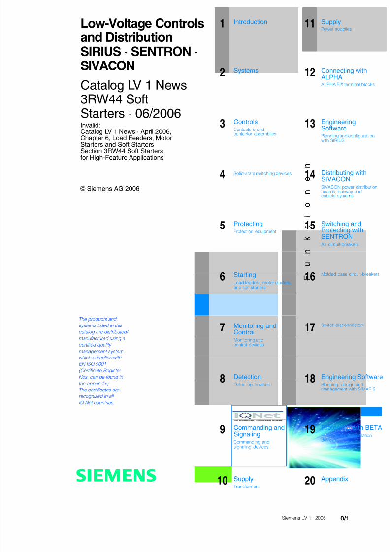
8122019 Arr Estado Solido
httpslidepdfcomreaderfullarr-estado-solido 340
InvalidCatalog LV 1 News middot April 2006Chapter 6 Load Feeders MotorStarters and Soft StartersSection 3RW44 Soft Startersfor High-Feature Applications
copy Siemens AG 2006
The products and
systems listed in this
catalog are distributed
manufactured using a
certified quality
management system
which complies with
EN ISO 9001
(Certificate Register
Nos can be found in
the appendix)The certificates are
recognized in all
IQ Net countries
1 Introduction
F
u
n
k
t
i
o
n
e
n
11 SupplyPower supplies
2 Systems 12 Connecting withALPHAALPHA FIX terminal blocks
3 ControlsContactors andcontactor assemblies
13 EngineeringSoftwarePlanning and configurationwith SIRIUS
4 Solid-state switching devices 14 Distributing withSIVACONSIVACON power distributio
boards busway andcubicle systems
5 ProtectingProtection equipment
15 Switching andProtecting withSENTRONAir circuit-breakers
6 StartingLoad feeders motor starters
and soft starters
16Molded case circuit-break
7 Monitoring andControlMonitoring andcontrol devices
17Switch disconnectors
8
DetectionDetecting devices
18
Engineering SoftwaPlanning design andmanagement with SIMARIS
9 Commanding andSignalingCommanding andsignaling devices
19 Protecting with BEBETA modular installationdevices
10 SupplyTransformers 20 Appendix
s
Low-Voltage Controlsand DistributionSIRIUS middot SENTRON middot SIVACON
Catalog LV 1 News
3RW44 SoftStarters middot 062006
8122019 Arr Estado Solido
httpslidepdfcomreaderfullarr-estado-solido 440
Niederspannungs-Schalttechnik
Delivery times (DT)
Preferred type
A 2 working days
B 1 week
C 3 weeks
D 6 week
X on request
Preferred types are available immediately fromstock ie are dispatched within 24 hours
Normal quantities of the products are usually deliv-red within the specified time following receipt ofyour order at our branch
In exceptional cases the actual delivery periodmay differ from that specified
The delivery periods apply up to the ramp at Siemens AG (products ready fordispatch) The transport times depend on the destination and type of shippingThe standard transport time for Germany is 1 day
The delivery times specified here represent the state of 062006 They are per-manently optimized Up-to-date information can be found atwwwsiemenscomautomationmall
Price units (PU)
The price unit defines the number of units sets ormeters to which the specified price and weight
apply
Packaging sizes (PS)
The packaging size defines the number eg ofunits sets or meters for outer packaging
Only the quantity defined by the packaging size ora multiple thereof can be ordered
For multi-unit packaging and recyclable packaging see Appendix of the LV 1catalog 2006
Price groups (PG)
Each product is assigned to a price group
Weight
The defined weight in kg refers to the price unit(PU)
Dimensions
All dimensions in mm
Explanations
LV1_News_00_03fm Seite 4 Dienstag 4 Juli 2006 1121 11
8122019 Arr Estado Solido
httpslidepdfcomreaderfullarr-estado-solido 540
3RW Soft Starters
62 General data
62 - Overview
63 3RW44 for High-Feature applications
63 - Overview63 - Application64 - Selection and ordering data
3RW Soft Starters
610 3RW44 for High-Feature applications610 - Function611 - Technical specifications625 - Characteristic curves626 - More information
629 Project planning aids
629 - Dimensional drawings631 - Schematics
Load Feeders MotorStarters and Soft Starters
Catalog
Technical Information
8122019 Arr Estado Solido
httpslidepdfcomreaderfullarr-estado-solido 640
3RW Soft Starters
General data
Overview
The advantages of the SIRIUS soft starters at a glancebull Soft starting and smooth ramp-down1)
bull Stepless startingbull Reduction of current peaksbull Avoidance of mains voltage fluctuations during startingbull Reduced load on the power supply network
bull Reduction of the mechanical load in the operating mechanismbull Considerable space savings and reduced wiring compared
with conventional startersbull Maintenance-free switchingbull Very easy handlingbull Fits perfectly in the SIRIUS modular system
Function is available
-- Function not available1) Only soft starting available for 3RW30 -1AA12 and 3RW312) Not available for 3RW30 033) Not possible in inside-delta circuit4) Trace function with Soft Starter ES5) For 3RW30 03 up to 230 V
6) Calculate soft starter and motor with size allowance where required
More information can be found on the Internet athttpwwwsiemenscomsoftstarter
SIRIUS 3RW3031 SIRIUS 3RW40 SIRIUS 3RW44Standard applications High-Feature applications
Rated current up to 40 degC A 3 100 134 432 29 1214
Rated operational voltage V 200 575 200 600 200 690
Motor rating at 400 Vbull Inline circuit kW 11 55 75 250 15 710bull Inside-delta circuit kW -- -- 22 1200
Temperature range degC -25 +60 -25 +60 0 +60
Soft startingramp-down 1)
Voltage ramp
Startingstopping voltage 40 100 40 100 20 100
Starting and ramp-down time s 0 20 0 20 1 360
Torque control -- --
Startingstopping torque -- -- 20 100
Torque limit -- -- 20 200
Ramp time s -- -- 1 360
Integral bypass contact system 2)
Intrinsic device protection --
Motor overload protection --
Thermistor motor protection -- --
Adjustable current limiting --
Inside-delta circuit -- --
Breakaway pulse -- --
Creep speed in both directions -- --
Pump ramp-down -- -- 6)
DC braking -- -- 3) 6)
Combined braking -- -- 3) 6)
Motor heating -- --
Communication -- -- with PROFIBUS DP (optional)
External display and operator module -- -- (optional)
Operating measured value display -- --
Error logbook -- --
Event list -- --
Slave pointer function -- --
Trace function -- -- 4)
Programmable control inputs and outputs -- --
Number of parameter sets 1 (2 with 3RW31) 1 3
Parameterization software (Soft Starter ES) -- --
Power semiconductors (thyristors) 2 controlled phases 2 controlled phases 3 controlled phases
Spring-loaded terminals (only 3RW30 03)
Screw terminals
ULCSA 5)
CE marking
Soft starting under heavy starting conditions -- -- 6)
Configuring support Win-Soft Starter the electronic selection slider ruler Technical Assistance ++49 911 895 5900
8122019 Arr Estado Solido
httpslidepdfcomreaderfullarr-estado-solido 740
3RW Soft Starters
3RW44for High-Feature applications
Overview
In addition to soft starting and soft ramp-down the solid-stateSIRIUS 3RW44 soft starters provide numerous functions for
higher-level requirements They cover a rating range up to710 kW (at 400 V) in the inline circuit and up to 1200 kW(at 400 V) in the inside-delta circuit
The SIRIUS 3RW44 soft starters are characterized by a compactdesign for space-saving and clearly arranged control cabinetlayouts For optimized motor starting and stopping the innova-tive SIRIUS 3RW44 soft starters are an attractive alternative withconsiderable savings potential compared to applications with afrequency converter The new torque control and adjustablecurrent limiting enable the High-Feature soft starters to be usedin nearly every conceivable task They guarantee the reliableavoidance of sudden torque applications and current peaksduring motor starting and stopping This creates savings poten-tial when calculating the size of the switchgear and when servic-ing the machinery installed Be it for inline circuits or inside-deltacircuits ndash the SIRIUS 3RW44 soft starter offers savings especiallyin terms of size and equipment costs
Combinations of various starting operating and ramp-downpossibilities ensure an optimum adaptation to the application-specific requirements Operating and commissioning can beperformed by means of the user-friendly keypad and a menu-prompted multi-line graphic display with background lightingThe optimized motor ramp-up and ramp-down can be effectedby means of just a few settings with a previously selectedlanguage Four-key operation and plain-text displays for eachmenu point guarantee full clarity at every moment of theparameterization and operation
Applicable standards
bull IEC 60947-4-2
bull ULCSA
Application
The SIRIUS 3RW44 solid-state soft starters are suitable for thetorque-controlled soft starting and smooth ramp-down as well as
braking of three-phase asynchronous motors
Application areas e g
bull Pumps
bull Ventilators
bull Compressors
bull Water transport
bull Conveying systems and lifts
bull Hydraulics
bull Machine tools
bull Mills
bull Saws
bull Breakers
bull Mixersbull Centrifuges
bull Industrial cooling and refrigerating systems
8122019 Arr Estado Solido
httpslidepdfcomreaderfullarr-estado-solido 840
3RW Soft Starters
3RW44for High-Feature applications
Selection and ordering data
1) 3RW44 2 3RW44 3 and 3RW44 4 soft starters with screw-typeterminals delivery time class (preferred type)
2) Control by way of the internal 24 V DC supply and direct control by meansof PLC possible
NoteSoft starter selection depends on the motors rated current
The 3RW44 solid-state soft starters are designed for normalstarting (class 10) (Inertia load of the overall operating mecha- nism JLoad lt 10 x JMotor starting current 350 x Ie for 20 s orsimilar load) For any other conditions of use the devices shouldbe selected using the Win-Soft Starter selection and simulationprogram See Technical Specifications for information aboutrated currents for ambient temperatures gt 40 degC and operatingfrequency
3RW44 27-1BC44 3RW44 36-6BC44 3RW44 47-6BC44 3RW44 58-6BC44
Ambient temperature 40 degC Ambient temperature 50 degC DT Order No Priceper PU
PU(UNITSET M)
PS PG Weightper PUapprox
Ratedopera-tionalcurrent I e
Rated output of three-phase inductionmotors for rated operational voltageU e
Ratedopera-tionalcurrent I e
Rated output of three-phaseinduction motors for ratedoperational voltage U e
230 V 400 V 500 V 690 V 1000 V 200 V 230 V 460 V 575 V
A kW kW kW kW kW A hp hp hp hp kg
Inline circuit rated operational voltage 200 460 V1)
29 55 15 -- -- -- 26 75 75 15 -- 3RW44 22-BC4 1 1 unit 131 490036 75 185 -- -- -- 32 10 10 20 -- 3RW44 23-BC4 1 1 unit 131 490047 11 22 -- -- -- 42 10 15 25 -- 3RW44 24-BC4 1 1 unit 131 4900
57 15 30 -- -- -- 51 15 15 30 -- 3RW44 25-BC4 1 1 unit 131 490077 185 37 -- -- -- 68 20 20 50 -- 3RW44 26-BC4 1 1 unit 131 490093 22 45 -- -- -- 82 25 25 60 -- 3RW44 27-BC4 1 1 unit 131 4900
Order No supplement for connection methods
bull With spring-loaded terminals 3bull With screw terminals 1
113 30 55 -- -- -- 100 30 30 75 -- B 3RW44 34-BC4 1 1 unit 131 7900134 37 75 -- -- -- 117 30 40 75 -- B 3RW44 35-BC4 1 1 unit 131 7900162 45 90 -- -- -- 145 40 50 100 -- B 3RW44 36-BC4 1 1 unit 131 7900
203 55 110 -- -- -- 180 50 60 125 -- B 3RW44 43-BC4 1 1 unit 131 10300250 75 132 -- -- -- 215 60 75 150 -- B 3RW44 44-BC4 1 1 unit 131 10300313 90 160 -- -- -- 280 75 100 200 -- B 3RW44 45-BC4 1 1 unit 131 10300
356 110 200 -- -- -- 315 100 125 250 -- B 3RW44 46-BC4 1 1 unit 131 10300432 132 250 -- -- -- 385 125 150 300 -- B 3RW44 47-BC4 1 1 unit 131 10300
551 160 315 -- -- -- 494 150 200 400 -- C 3RW44 53-BC4 1 1 unit 131 50000615 200 355 -- -- -- 551 150 200 450 -- C 3RW44 54-BC4 1 1 unit 131 50000693 200 400 -- -- -- 615 200 250 500 -- C 3RW44 55-BC4 1 1 unit 131 50000
780 250 450 -- -- -- 693 200 250 600 -- C 3RW44 56-BC4 1 1 unit 131 50000880 250 500 -- -- -- 780 250 300 700 -- C 3RW44 57-BC4 1 1 unit 131 50000970 315 560 -- -- -- 850 300 350 750 -- C 3RW44 58-BC4 1 1 unit 131 50000
Order No supplement for connection methods
bull With spring-loaded terminals 2bull With screw terminals 6
Order No supplement for the rated control supply voltage U s2)
bull 115 V AC 3bull 230 V AC 4
8122019 Arr Estado Solido
httpslidepdfcomreaderfullarr-estado-solido 940
3RW Soft Starters
3RW44for High-Feature applications
1) 3RW44 2 3RW44 3 and 3RW44 4 soft starters with screw-typeterminals delivery time class A
2) Control by way of the internal 24 V DC supply and direct control by meansof PLC possible
NoteSoft starter selection depends on the motors rated current
The 3RW44 solid-state soft starters are designed for normalstarting (class 10) (Inertia load of the overall operating mecha-nism J Load lt 10 x J Motor starting current 350 x I e for 20 s orsimilar load) For any other conditions of use the devices shouldbe selected using the Win-Soft Starter selection and simulationprogram See Technical Specifications for information aboutrated currents for ambient temperatures gt 40 degC and operating
frequency
Ambient temperature 40 degC Ambient temperature 50 degC DT Order No Priceper PU
PU(UNITSET M)
PS PG Weightper PUapprox
Ratedopera-
tionalcurrent I e
Rated output of three-phaseinduction motors for rated operational
voltage U e
Ratedopera-
tionalcurrent I e
Rated output of three-phaseinduction motors for rated
operational voltage U e
230 V 400 V 500 V 690 V 1000 V 200 V 230 V 460 V 575 V
A kW kW kW kW kW A hp hp hp hp kg
Inline circuit rated operational voltage 400 600 V1)
29 -- 15 185 -- -- 26 -- -- 15 20 A 3RW44 22-BC5 1 1 unit 131 490036 -- 185 22 -- -- 32 -- -- 20 25 A 3RW44 23-BC5 1 1 unit 131 490047 -- 22 30 -- -- 42 -- -- 25 30 A 3RW44 24-BC5 1 1 unit 131 4900
57 -- 30 37 -- -- 51 -- -- 30 40 A 3RW44 25-BC5 1 1 unit 131 490077 -- 37 45 -- -- 68 -- -- 50 50 A 3RW44 26-BC5 1 1 unit 131 490093 -- 45 55 -- -- 82 -- -- 60 75 A 3RW44 27-BC5 1 1 unit 131 4900
Order No supplement for connection methods
bull With spring-loaded terminals 3bull With screw terminals 1
113 -- 55 75 -- -- 100 -- -- 75 75 B 3RW44 34-BC5 1 1 unit 131 7900134 -- 75 90 -- -- 117 -- -- 75 100 B 3RW44 35-BC5 1 1 unit 131 7900
162 -- 90 110 -- -- 145 -- -- 100 125 B 3RW44 36-BC5 1 1 unit 131 7900
203 -- 110 132 -- -- 180 -- -- 125 150 B 3RW44 43-BC5 1 1 unit 131 10300250 -- 132 160 -- -- 215 -- -- 150 200 B 3RW44 44-BC5 1 1 unit 131 10300313 -- 160 200 -- -- 280 -- -- 200 250 B 3RW44 45-BC5 1 1 unit 131 10300
356 -- 200 250 -- -- 315 -- -- 250 300 B 3RW44 46-BC5 1 1 unit 131 10300432 -- 250 315 -- -- 385 -- -- 300 400 B 3RW44 47-BC5 1 1 unit 131 10300
551 -- 315 355 -- -- 494 -- -- 400 500 C 3RW44 53-BC5 1 1 unit 131 50000615 -- 355 400 -- -- 551 -- -- 450 600 C 3RW44 54-BC5 1 1 unit 131 50000693 -- 400 500 -- -- 615 -- -- 500 700 C 3RW44 55-BC5 1 1 unit 131 50000
780 -- 450 560 -- -- 693 -- -- 600 750 C 3RW44 56-BC5 1 1 unit 131 50000880 -- 500 630 -- -- 780 -- -- 700 850 C 3RW44 57-BC5 1 1 unit 131 50000970 -- 560 710 -- -- 850 -- -- 750 950 C 3RW44 58-BC5 1 1 unit 131 50000
Order No supplement for connection methods
bull With spring-loaded terminals 2bull With screw terminals 6
Order No supplement for the rated control supply voltage U s2)
bull 115 V AC 3bull 230 V AC 4
You can order this quantity or a multiple thereof
8122019 Arr Estado Solido
httpslidepdfcomreaderfullarr-estado-solido 1040
3RW Soft Starters
3RW44for High-Feature applications
1) Control by way of the internal 24 V DC supply and direct control by meansof PLC possible
NoteSoft starter selection depends on the motors rated current
The 3RW44 solid-state soft starters are designed for normalstarting (class 10) (Inertia load of the overall operating mecha- nism J Load lt 10 x J Motor starting current 350 x I e for 20 s orsimilar load) For any other conditions of use the devices shouldbe selected using the Win-Soft Starter selection and simulationprogram See Technical Specifications for information aboutrated currents for ambient temperatures gt 40 degC and operatingfrequency
Ambient temperature 40 degC Ambient temperature 50 degC DT Order No Priceper PU
PU(UNITSET M)
PS PG Weightper PUapprox
Ratedopera-
tionalcurrent I e
Rated output of three-phaseinduction motors for rated operational
voltage U e
Ratedopera-
tionalcurrent I e
Rated output of three-phaseinduction motors for rated
operational voltage U e
230 V 400 V 500 V 690 V 1000 V 200 V 230 V 460 V 575 V
A kW kW kW kW kW A hp hp hp hp kg
Inline circuit rated operational voltage 400 690 V
29 -- 15 185 30 -- 26 -- -- 15 20 B 3RW44 22-BC6 1 1 unit 131 490036 -- 185 22 37 -- 32 -- -- 20 25 B 3RW44 23-BC6 1 1 unit 131 490047 -- 22 30 45 -- 42 -- -- 25 30 B 3RW44 24-BC6 1 1 unit 131 4900
57 -- 30 37 55 -- 51 -- -- 30 40 B 3RW44 25-BC6 1 1 unit 131 490077 -- 37 45 75 -- 68 -- -- 50 50 B 3RW44 26-BC6 1 1 unit 131 490093 -- 45 55 90 -- 82 -- -- 60 75 B 3RW44 27-BC6 1 1 unit 131 4900
Order No supplement for connection methods
bull With spring-loaded terminals 3bull With screw terminals 1
113 -- 55 75 110 -- 100 -- -- 75 75 B 3RW44 34-BC6 1 1 unit 131 7900134 -- 75 90 132 -- 117 -- -- 75 100 B 3RW44 35-BC6 1 1 unit 131 7900
162 -- 90 110 160 -- 145 -- -- 100 125 B 3RW44 36-BC6 1 1 unit 131 7900
203 -- 110 132 200 -- 180 -- -- 125 150 B 3RW44 43-BC6 1 1 unit 131 10300250 -- 132 160 250 -- 215 -- -- 150 200 B 3RW44 44-BC6 1 1 unit 131 10300313 -- 160 200 315 -- 280 -- -- 200 250 B 3RW44 45-BC6 1 1 unit 131 10300
356 -- 200 250 355 -- 315 -- -- 250 300 B 3RW44 46-BC6 1 1 unit 131 10300432 -- 250 315 400 -- 385 -- -- 300 400 B 3RW44 47-BC6 1 1 unit 131 10300
551 -- 315 355 560 -- 494 -- -- 400 500 C 3RW44 53-BC6 1 1 unit 131 50000615 -- 355 400 630 -- 551 -- -- 450 600 C 3RW44 54-BC6 1 1 unit 131 50000693 -- 400 500 710 -- 615 -- -- 500 700 C 3RW44 55-BC6 1 1 unit 131 50000
780 -- 450 560 800 -- 693 -- -- 600 750 C 3RW44 56-BC6 1 1 unit 131 50000880 -- 500 630 900 -- 780 -- -- 700 850 C 3RW44 57-BC6 1 1 unit 131 50000970 -- 560 710 1000 -- 850 -- -- 750 950 C 3RW44 58-BC6 1 1 unit 131 50000
Order No supplement for connection methods
bull With spring-loaded terminals 2bull With screw terminals 6
Order No supplement for the rated control supply voltage U s1)
bull 115 V AC 3bull 230 V AC 4
8122019 Arr Estado Solido
httpslidepdfcomreaderfullarr-estado-solido 1140
3RW Soft Starters
3RW44for High-Feature applications
1) In the selection table the unit rated operational current I e refers to the
three-phase motors rated operational current in the inside-delta circuitThe actual current of the unit is approx 58 of this value
2) 3RW44 2 3RW44 3 and 3RW44 4 soft starters with screw-typeterminals delivery time class (preferred type)
3) Control by way of the internal 24 V DC supply and direct control by meansof PLC possible
NoteSoft starter selection depends on the motors rated current
The 3RW44 solid-state soft starters are designed for normalstarting (class 10) (Inertia load of the overall operatingmechanism JLoad lt 10 x JMotor starting current 350 x Ie for20 s or similar load) For any other conditions of use the devicesshould be selected using the Win-Soft Starter selection andsimulation program See Technical Specifications for informationabout rated currents for ambient temperatures gt 40 degC andoperating frequency
3RW44 27-1BC44 3RW44 36-6BC44 3RW44 47-6BC44 3RW44 58-6BC44
Ambient temperature 40 degC Ambient temperature 50 degC DT Order No Priceper PU
PU(UNITSET M)
PS PG Weightper PUapprox
Ratedopera-tionalcurrent I e
1)
Rated output of three-phase inductionmotors for rated operational voltageU e
Ratedopera-tionalcurrent I e
Rated output of three-phaseinduction motors for ratedoperational voltage U e
230 V 400 V 500 V 690 V 1000 V 200 V 230 V 460 V 575 V
A kW kW kW kW kW A hp hp hp hp kgInside-delta circuits rated operational voltage 200 460 V2)
50 15 22 -- -- -- 45 10 15 30 -- B 3RW44 22-BC4 1 1 unit 131 490062 185 30 -- -- -- 55 15 20 40 -- B 3RW44 23-BC4 1 1 unit 131 490081 22 45 -- -- -- 73 20 25 50 -- B 3RW44 24-BC4 1 1 unit 131 4900
99 30 55 -- -- -- 88 25 30 60 -- B 3RW44 25-BC4 1 1 unit 131 4900133 37 75 -- -- -- 118 30 40 75 -- B 3RW44 26-BC4 1 1 unit 131 4900161 45 90 -- -- -- 142 40 50 100 -- B 3RW44 27-BC4 1 1 unit 131 4900
Order No supplement for connection methods
bull With spring-loaded terminals 3bull With screw terminals 1
196 55 110 -- -- -- 173 50 60 125 -- B 3RW44 34-BC4 1 1 unit 131 7900232 75 132 -- -- -- 203 60 75 150 -- B 3RW44 35-BC4 1 1 unit 131 7900281 90 160 -- -- -- 251 75 100 200 -- B 3RW44 36-BC4 1 1 unit 131 7900
352 110 200 -- -- -- 312 100 125 250 -- B 3RW44 43-BC4 1 1 unit 131 10300433 132 250 -- -- -- 372 125 150 300 -- B 3RW44 44-BC4 1 1 unit 131 10300542 160 315 -- -- -- 485 150 200 400 -- B 3RW44 45-BC4 1 1 unit 131 10300
617 200 355 -- -- -- 546 150 200 450 -- B 3RW44 46-BC4 1 1 unit 131 10300748 250 400 -- -- -- 667 200 250 600 -- B 3RW44 47-BC4 1 1 unit 131 10300
954 315 560 -- -- -- 856 300 350 750 -- C 3RW44 53-BC4 1 1 unit 131 500001065 355 630 -- -- -- 954 350 400 850 -- C 3RW44 54-BC4 1 1 unit 131 500001200 400 710 -- -- -- 1065 350 450 950 -- C 3RW44 55-BC4 1 1 unit 131 50000
1351 450 800 -- -- -- 1200 450 500 1050 -- C 3RW44 56-BC4 1 1 unit 131 500001524 500 900 -- -- -- 1351 450 600 1200 -- C 3RW44 57-BC4 1 1 unit 131 500001680 560 1000 -- -- -- 1472 550 650 1300 -- C 3RW44 58-BC4 1 1 unit 131 50000
Order No supplement for connection methods
bull With spring-loaded terminals 2bull With screw terminals 6
Order No supplement for the rated control supply voltage U s3)
bull 115 V AC 3bull 230 V AC 4
You can order this quantity or a multiple thereof
8122019 Arr Estado Solido
httpslidepdfcomreaderfullarr-estado-solido 1240
3RW Soft Starters
3RW44for High-Feature applications
1) In the selection table the unit rated operational current I e refers to thethree-phase motors rated operational current in the inside-delta circuitThe actual current of the unit is approx 58 of this value
2) 3RW44 2 3RW44 3 and 3RW44 4 soft starters with screw-typeterminals delivery time class A
3) Control by way of the internal 24 V DC supply and direct control by meansof PLC possible
Accessories
NoteSoft starter selection depends on the motors rated current
The 3RW44 solid-state soft starters are designed for normalstarting (class 10) (Inertia load of the overall operatingmechanism J Load lt 10 x J Motor starting current 350 x I e for20 s or similar load) For any other conditions of use the devicesshould be selected using the Win-Soft Starter selection andsimulation program See Technical Specifications for informationabout rated currents for ambient temperatures gt 40 degC andoperating frequency
Ambient temperature 40 degC Ambient temperature 50 degC DT Order No Priceper PU
PU(UNITSET M)
PS PG Weightper PUapprox
Ratedopera-
tionalcurrent I e
1)
Rated output of three-phaseinduction motors for rated opera-
tional voltage U e
Ratedopera-
tionalcurrent I e
Rated output of three-phaseinduction motors for rated
operational voltage U e
230 V 400 V 500 V 690 V 1000 V 200 V 230 V 460 V 575 V
A kW kW kW kW kW A hp hp hp hp kg
Inside-delta circuits rated operational voltage 400 600 V2)
50 -- 22 30 -- -- 45 -- -- 30 40 B 3RW44 22-BC5 1 1 unit 131 490062 -- 30 37 -- -- 55 -- -- 40 50 B 3RW44 23-BC5 1 1 unit 131 490081 -- 45 45 -- -- 73 -- -- 50 60 B 3RW44 24-BC5 1 1 unit 131 4900
99 -- 55 55 -- -- 88 -- -- 60 75 B 3RW44 25-BC5 1 1 unit 131 4900133 -- 75 90 -- -- 118 -- -- 75 100 B 3RW44 26-BC5 1 1 unit 131 4900161 -- 90 110 -- -- 142 -- -- 100 125 B 3RW44 27-BC5 1 1 unit 131 4900
Order No supplement for connection methods
bull With spring-loaded terminals 3bull With screw terminals 1
196 -- 110 132 -- -- 173 -- -- 125 150 B 3RW44 34-BC5 1 1 unit 131 7900232 -- 132 160 -- -- 203 -- -- 150 200 B 3RW44 35-BC5 1 1 unit 131 7900
281 -- 160 200 -- -- 251 -- -- 200 250 B 3RW44 36-BC5 1 1 unit 131 7900
352 -- 200 250 -- -- 312 -- -- 250 300 B 3RW44 43-BC5 1 1 unit 131 10300433 -- 250 315 -- -- 372 -- -- 300 350 B 3RW44 44-BC5 1 1 unit 131 10300542 -- 315 355 -- -- 485 -- -- 400 500 B 3RW44 45-BC5 1 1 unit 131 10300
617 -- 355 450 -- -- 546 -- -- 450 600 B 3RW44 46-BC5 1 1 unit 131 10300748 -- 400 500 -- -- 667 -- -- 600 750 B 3RW44 47-BC5 1 1 unit 131 10300
954 -- 560 630 -- -- 856 -- -- 750 950 C 3RW44 53-BC5 1 1 unit 131 500001065 -- 630 710 -- -- 954 -- -- 850 1050 C 3RW44 54-BC5 1 1 unit 131 500001200 -- 710 800 -- -- 1065 -- -- 950 1200 C 3RW44 55-BC5 1 1 unit 131 50000
1351 -- 800 900 -- -- 1200 -- -- 1050 1350 C 3RW44 56-BC5 1 1 unit 131 500001524 -- 900 1000 -- -- 1351 -- -- 1200 1500 C 3RW44 57-BC5 1 1 unit 131 500001680 -- 1000 1200 -- -- 1472 -- -- 1300 1650 C 3RW44 58-BC5 1 1 unit 131 50000
Order No supplement for connection methods
bull With spring-loaded terminals 2bull With screw terminals 6
Order No supplement for the rated control supply voltage U s3)
bull 115 V AC 3bull 230 V AC 4
Forsoft starters Version DT Order No Priceper PU PU(UNITSET M)
PS PG Weightper PUapprox
Type kg
Soft Starter ES 2006 PC communication program
Soft Starter ES 2006 Smart
Parameterization and service software forSIRIUS 3RW44 soft starters for parameterizingthrough the system interface on the deviceExecutes on PCPG under Windows 2000XPwithout PC cableType of supply CD single license
3ZS1 313-1CC10-0YA0 1 1 unit 131 0230
3ZS1 313-1CC10-0YA0 Soft Starter ES 2006 Professional
Parameterization and service software forSIRIUS 3RW44 soft starters for parameterizingthrough the system interface on the device andPROFIBUS DP interface (PROFIBUS as optional commu-nication module necessary)Executes on PCPG under Windows 2000XPwithout PC cableType of supply CD single license
A 3ZS1 313-2CC10-0YA0 1 1 unit 131 0230
8122019 Arr Estado Solido
httpslidepdfcomreaderfullarr-estado-solido 1340
3RW Soft Starters
3RW44for High-Feature applications
Spare parts
Forsoft starters
Version DT Order No Priceper PU
PU(UNITSET M)
PS PG Weightper PUapprox
Type kg
PC cables
For PCPG communication with SIRIUS 3RW44soft starters
through the system interface for connecting tothe serial interface of the PCPG
B 3UF7 940-0AA00-0 1 1 unit 131 0150
Box terminal blocks for soft starters
Box terminal blocks
3RW44 2 Included in del ivery
3RW44 3 bull Up to 70 mm2 3RT19 55-4G 1 1 unit 101 0237
bull Up to 120 mm2 3RT19 56-4G 1 1 unit 101 0270
3RW44 3 bull Up to 240 mm2 3RT19 66-4G 1 1 unit 101 0676
PROFIBUS Communication moduleModule to be plugged into the soft starter to connect thesoft starter to the PROFIBUS net
A 3RW4 900-0KC00 1 1 unit 131 0320
External display and operation module
to show and operate the fonctions supplied by the softstarter via externally mounted display and operationmodule(for example in the cubicle door)
A 3RW4 900-0AC00 1 1 unit 131 0320
Connection cable
from serial interface of 3RW44 soft starter to external dis-play and operation modulebull Length 05 m flat B 3UF7 932-0AA00-0 1 1 unit 131 0020bull Length 05 m round A 3UF7 932-0BA00-0 1 1 unit 131 0050bull Length10 m round A 3UF7 937-0BA00-0 1 1 unit 131 0100bull Length25 m round A 3UF7 933-0BA00-0 1 1 unit 131 0150
Covers for soft starters
Terminal covers for box terminals
Additional touch protection to be fitted at the boxterminals (2 units required per device)
3RW44 2 and3RW44 3
3RT19 56-4EA2 1 1 unit 101 0028
3RW44 4 3RT19 66-4EA2 1 1 unit 101 0038
Terminal covers for cable lugs and busbarconnections
3RW44 2 and3RW44 3
3RT19 56-4EA1 1 1 unit 101 0067
3RW44 4 3RT19 66-4EA1 1 1 unit 101 0124
Forsoft starters
Version DT Order No Priceper PU
PU(UNITSET M)
PS PG Weightper PUapprox
Type kg
Fans
Fans
3RW44 2 and3RW44 3
115 VAC 3RW49 36-8VX30 1 1 unit 131 0300230 VAC 3RW49 36-8VX40 1 1 unit 131 0300
3RW44 4 115 V AC 3RW49 47-8VX30 1 1 unit 131 0500230 VAC 3RW49 47-8VX40 1 1 unit 131 0500
3RW44 5 115 V AC 3RW49 57-8VX30 1 1 unit 131 0800230 VAC 3RW49 57-8VX40 1 1 unit 131 0800
You can order this quantity or a multiple thereof
8122019 Arr Estado Solido
httpslidepdfcomreaderfullarr-estado-solido 1440
3RW Soft Starters
3RW44for High-Feature applications
Function
Equipped with modern ergonomic user prompting theSIRIUS 3RW44 soft starters can be commissioned quickly and
easily using a keypad and a menu-prompted multi-line displaywith background lighting Motor starting and deceleration areoptimized quickly easily and safely with just a few settings in aselectable language Four-key operation and plain-text displaysfor each menu point guarantee full clarity at every moment of theparameterization and operation Measurement values and oper-ating values as well as warning messages and fault indicationsare output continuously on the front panel during operation andwhen control voltage is applied An external display and opera-tor module can be connected by means of a connecting cableto the soft starter thus enabling active indications and the like tobe read directly from the control cabinet door
The SIRIUS 3RW44 soft starters are equipped with optimumfunctionality An integral bypass contact system reduces thepower loss of the soft starter during operation This reliablyprevents heating of the switchgear environment TheSIRIUS 3RW44 soft starters have internal intrinsic deviceprotection This prevents thermal overloading of the powersections thyristors eg due to unacceptably high closingoperations
Wiring work for installing an additional motor overload relay is nolonger needed as the SIRIUS 3RW44 soft starters perform thisfunction too In addition they offer adjustable trip classes and athermistor motor protection function As an option the thyristorscan also be protected by SITOR semi-conductor fuses fromshort-circuiting And even inrush current peaks are reliablyavoided thanks to adjustable current limiting
As a further option the SIRIUS 3RW44 soft starters can beupgraded with a PROFIBUS DP module Thanks to their commu-nication capability and their programmable control inputs andrelay outputs the SIRIUS 3RW44 soft starters can be very easily
and quickly integrated in higher-level controllersIn addition a creep speed function is available for positioningand setting jobs With this function the motor can be controlledin both directions of rotation with reduced torque and an adjust-able low speed
On the other hand the SIRIUS 3RW44 soft starters offer a newcombined DC braking function for the fast stopping of drivingloads
Highlights bull Soft starting with breakaway pulse torque control or voltage
ramp and adjustable torque or current limiting as well as anycombination of these depending on load type
bull Integrated bypass contact system to minimize dissipatedpower
bull Various setting options for the starting parameters such asstarting torque starting voltage ramp-up and ramp-downtime and much more in three separate parameter sets
bull Start-up detectionbull Inside-delta circuit for savings in terms of size and equipment
costsbull Various ramp-down modes selectable free ramp-down
torque-controlled pump stopping combined DC brakingbull Solid-state motor overload and intrinsic device protectionbull Thermistor motor protectionbull Keypad with a menu-controlled multi-line graphic display with
background lighting
bull Interface for communication with the PC for more accuratesetting of the parameters as well as for control and monitoringbull Simple adaptation to the motor feederbull Simple mounting and commissioningbull Display of operating states and fault signalsbull Connection to PROFIBUS with optional PROFIBUS DP modulebull External display and operator modulebull System voltages from 200 to 690 V 50 to 60 Hzbull Applicable up to 60 degC (derating from 40 degC)
8122019 Arr Estado Solido
httpslidepdfcomreaderfullarr-estado-solido 1540
3RW Soft Starters
3RW44for High-Feature applications
Technical specifications
Type 3RW44 -BC3 3RW44 -BC4Terminal
Control electronics
Rated valuesRated control supply voltage A1A2PE V 115 AC 230 ACbull Tolerance -15+10 -15+10Rated control supply current STANDBY mA 30 20
Rated control supply current ONbull 3RW44 2 mA 300 170bull 3RW44 3 mA 500 250bull 3RW44 4 mA 750 400bull 3RW44 5 mA 450 200
Maximum current (pickup bypass)bull 3RW44 2 mA 1000 500bull 3RW44 3 mA 2500 1250bull 3RW44 4 mA 6000 3000bull 3RW44 5 mA 4500 2500
Rated frequency Hz 50 60 50 60bull Tolerance plusmn10 plusmn10
Type 3RW44 Terminal Factory presetting
Control electronics
Control inputsInput 1 IN1 Start motor right parameter set 1Input 2 IN2 No actionInput 3 IN3 No actionInput 4 IN4 Trip reset
Supply L+L-bull Rated operational current mA Approx 10 per input to DIN 19240bull Rated operational voltage L+ Internal voltage 24 V DC from inter-
nal supply through terminal L+ toIN1 IN4 Maximum load at L+approx 55 mA
L- External voltage DC external voltage(to DIN19240) through terminals
L- and IN1 IN4(min 12 V DC max 30 V DC)
Thermistor motor protection inputInput T1T2 PTC type A or Thermoclick Deactivated
Relay outputs (floating auxiliary contacts)Output 1 1314 ON periodOutput 2 2324 No actionOutput 3 3334 No actionOutput 4 959698 Group fault
Switching capacity of the relay outputs230 VAC-15 A 3 at 240 V24 VDC-13 A 1 at 24 VProtection against overvoltages Protection by means of Varistor through relay contactShort-circuit protection 4 A gLgG operational class
6 A quick (fuse is not included in scope of supply)
Protective functions
Motor protection functionsTrips in the event of Thermal overloading of the motor
Trip class to IEC 60947-4-1 Class 510152030 10Phase failure sensitivity gt 40
Overload warning yesReset and recovery ManualAutomatic ManualReset option after tripping ManualAutomatic ManualRecovery time min 1 30 1
Device protection functionsTrips in the event of Thermal overloading of the thyristorsReset option after tripping ManualAutomatic ManualRecovery time min 05
8122019 Arr Estado Solido
httpslidepdfcomreaderfullarr-estado-solido 1640
3RW Soft Starters
3RW44for High-Feature applications
Type 3RW44 Factory presetting
Control times and parameters
Control timesClosing delay (with connected control voltage) ms lt 50Closing delay (automatic mode) ms lt 4000Recovery time (closing command in active ramp-down) ms lt 100
Mains failure bridging timeControl supply voltage ms 100
Mains failure response timeLoad current circuit ms 100
Reclosing lockout after overload tripMotor protection trip min 1 30 1Device protection trip s 30
Setting options for startingVoltage ramp for starting voltage 20 100 30Torque control for starting torque 20 100 50Torque control for limit torque 20 200 150
Starting time s 0 360 20Maximum starting time s 1 1000 DeactivatedCurrent limit value 125 550 450
Breakaway voltage 40 100 80Breakaway time s 0 2 DeactivatedMotor heat output 0 100 0
Creep mode LeftRight runningSpeed factor as function of rated speed (n = n rated factor) 3 21 7Creep torque (reference variable depends on the motor used but isalways smaller than the rated torque of the motor)
20 100 50
Setting options for ramp-downTorque control for stopping torque 10 100 10Ramp-down time s 0 360 10Dynamic braking torque 20 100 50DC braking torque 20 100 50
Operating indicationsTest voltageTest mains phasesReady to start
Start active
Motor runningRamp-down active
Warningserror signalsMains voltage missingLeading-edge phase error
Phase failurebull L1bull L2bull L3
Missing load phasebull T1bull T2bull T3
Failurebull Contact element 1 (thyristor)bull Contact element 2 (thyristor)bull Contact element 3 (thyristor)
Flash memory faulty
Supply voltagebull Below 75 bull Below 85 bull Over 110
Current unbalance exceededThermal motor model overload
Prewarning limit exceededbull Motor heatingbull Time-related trip reserve
Bypass elements defectiveMains voltage too high
Device not namedWrong naming versionCurrent range exceeded
Motor blocking ndash shutdownCurrent limit exceeded
Power section
bull Overheatedbull OvertemperatureEmergency active
8122019 Arr Estado Solido
httpslidepdfcomreaderfullarr-estado-solido 1740
3RW Soft Starters
3RW44for High-Feature applications
1) Parameter motor left possible only in conjunction with creep mode
Type 3RW44 Factory presetting
Control times and parameters
Warningserror signals (contd)Temperature sensorbull Overloadbull Open-circuitbull Short-circuit
Ground faultbull Detectedbull Shutdown
Connection abort in manual modeMax number of starts exceeded I e limit value overshootundershoot
Cooling timebull Motor activebull Switch block active
Heat sink sensorbull Open-circuitbull Short-circuit
Quick-stop functionSwitch block faulty I e class setting not permissible
Control inputsInput 1 Motor right parameter set 1Input 2 No actionInput 3 No actionInput 4 Trip reset
Parameterizing options for control inputs 1 4 No actionLocal manual modeEmergency startCreep speedQuick-stopTrip reset
Motor right parameter set 1Motor left parameter set 11) Motor right parameter set 2Motor left parameter set 21) Motor right parameter set 3Motor left parameter set 31)
Relay outputsOutput 1 ON periodOutput 2 No actionOutput 3 No actionOutput 4 Group fault
Parameterizing options for relay outputs 1 3 No actionPAA output 1PAA output 2
Input 1Input 2Input 3Input 4
Ramp-upOperationBypassRamp-downON periodCommand motor on
FanDC braking contactor
Group warningGroup faultBus faultDevice error
Power onReady to start
Motor temperature sensors Deactivated DeactivatedThermoclickPTC type A
8122019 Arr Estado Solido
httpslidepdfcomreaderfullarr-estado-solido 1840
3RW Soft Starters
3RW44for High-Feature applications
1) Current limit on soft starter set to 350 I M
2) For intermittent duty S4 with ON period = 70 T u = 40 degC stand-aloneinstallation vertical The quoted operating frequencies do not apply forautomatic mode
3) Maximum adjustable rated motor current I M dependent on CLASS setting
Type 3RW44 -BC4 3RW44 -BC5 3RW44 -BC6
Power electronics
Rated operational voltage for inline circuit V 200 460 AC 400 600 AC 400 690 AC
Tolerance -15+10 -15+10 -15+10Rated operational voltage for inside-delta circuit V 200 460 AC 400 600 AC 400 600 ACTolerance -15+10 -15+10 -15+10
Rated frequency Hz 50 60Tolerance plusmn10
Continuous operation at 40 degC ( of I e) 115
Minimum load ( of set motor current I M) 8
Maximum conductor length between soft starter and motor m 200
Permissible installation height m 5000 (derating from 1000 see characteristics) higher on request
Permissible mounting position
Permissible ambient temperatureOperation degC 0 +60 (derating from +40)Storage degC -25 +80
Degree of protection IP00
Type 3RW44 22 3RW44 23 3RW44 24 3RW44 25 3RW44 26 3RW44 27
Power electronics
Rated operational current I e 29 36 47 57 77 93
Load rating with rated operational current I ebull Acc to IEC and ULCSA for individual mounting
at 405060 degC AC-53a A 292623 363229 474237 575145 776859 938272
Smallest adjustable rated motor current I Mfor the motor overload protection
A 5 7 9 11 15 18
Power lossbull In operation after completed ramp-up with uninterrupted rated
operational current (40 degC) approx W 8 10 32 36 45 55bull During starting with current limit set to 350 I M (40 degC) W 400 470 600 725 940 1160
Permissible rated motor current and starts per hour
bull Normal starting (Class 5)- Rated motor current I M
1) starting time 5 s A 29 36 47 57 77 93- Starts per hour2) 1h 41 34 41 41 41 41
- Rated motor current I M1)3) starting time 10 s A 29 36 47 57 77 93
- Starts per hour2) 1h 20 15 20 20 20 20
bull Normal starting (Class 10)- Rated motor current I M
1) starting time 10 s A 29 36 47 57 77 93- Starts per hour2) 1h 20 15 20 20 20 20
- Rated motor current I M1)3) starting time 20 s A 29 36 47 57 77 93
- Starts per hour2) 1h 10 6 10 10 8 8
bull Normal starting (Class 15)- Rated motor current I M
1) starting time 15 s A 29 36 47 57 77 93- Starts per hour2) 1h 13 9 13 13 13 13
- Rated motor current I M1)3) starting time 30 s A 29 36 47 57 77 93
- Starts per hour2) 1h 6 4 6 6 6 6
bull For heavy starting (Class 20)- Rated motor current I M
1) starting time 20 s A 29 36 47 57 73 88- Starts per hour2) 1h 10 6 10 10 10 10
- Rated motor current I M1)3) starting time 40 s A 29 36 47 57 73 88
- Starts per hour2) 1h 4 2 4 5 18 08
bull For very heavy starting (Class 30)- Rated motor current I M
1) starting time 30 s A 29 36 44 57 65 77- Starts per hour2) 1h 6 4 6 6 6 6
- Rated motor current I M1)3) starting time 60 s A 29 36 44 57 65 77
- Starts per hour2) 1h 18 08 33 15 2 1
8122019 Arr Estado Solido
httpslidepdfcomreaderfullarr-estado-solido 1940
3RW Soft Starters
3RW44for High-Feature applications
1) Current limit on soft starter set to 350 I M
2) For intermittent duty S4 with ON period = 70 T u = 40 degC stand-aloneinstallation vertical The quoted operating frequencies do not apply forautomatic mode
3) Maximum adjustable rated motor current I M dependent on CLASS setting
Type 3RW44 34 3RW44 35 3RW44 36
Power electronics
Rated operational current I e 113 134 162
Load rating with rated operational current I ebull Acc to IEC and ULCSA for individual mounting AC-53a
- at 40 degC A 113 134 162- at 50 degC A 100 117 145- at 60 degC A 88 100 125
Smallest adjustable rated motor current I Mfor the motor overload protection
A 22 26 32
Power lossbull In operation after completed ramp-up with uninterrupted rated
operational current (40 degC) approx W 64 76 95bull During starting with current limit set to 350 I M (40 degC) W 1350 1700 2460
Permissible rated motor current and starts per hour
bull Normal starting (Class 5)- Rated motor current I M
1) starting time 5 s A 113 134 162- Starts per hour2) 1h 41 39 41
- Rated motor current I M1)3) starting time 10 s A 113 134 162
- Starts per hour2) 1h 20 15 20
bull Normal starting (Class 10)- Rated motor current I M
1) starting time 10 s A 113 134 162- Starts per hour2) 1h 20 15 20
- Rated motor current I M1)3) starting time 20 s A 113 134 162
- Starts per hour2) 1h 9 6 7
bull Normal starting (Class 15)- Rated motor current I M
1) starting time 15 s A 113 134 162- Starts per hour2) 1h 13 9 12
- Rated motor current I M1)3) starting time 30 s A 113 134 162
- Starts per hour2) 1h 6 6 1
bull For heavy starting (Class 20)- Rated motor current I M
1) starting time 20 s A 106 125 147- Starts per hour2) 1h 9 9 10
- Rated motor current I M1)3) starting time 40 s A 106 125 147
- Starts per hour2) 1h 15 2 1
bull For very heavy starting (Class 30)- Rated motor current I M
1) starting time 30 s A 91 110 120
- Starts per hour2) 1h 6 6 6- Rated motor current I M
1)3) starting time 60 s A 91 110 120- Starts per hour2) 1h 2 2 2
8122019 Arr Estado Solido
httpslidepdfcomreaderfullarr-estado-solido 2040
3RW Soft Starters
3RW44for High-Feature applications
1) Current limit on soft starter set to 350 I M
2) For intermittent duty S4 with ON period = 70 T u = 40 degC stand-aloneinstallation vertical The quoted operating frequencies do not apply forautomatic mode
3) Maximum adjustable rated motor current I M dependent on CLASS setting
Type 3RW44 43 3RW44 44 3RW44 45 3RW44 46 3RW44 47
Power electronics
Rated operational current I e 203 250 313 356 432
Load rating with rated operational current I ebull Acc to IEC and ULCSA for individual mounting AC-53a
- at 40 degC A 203 250 313 356 432- at 50 degC A 180 215 280 315 385- at 60 degC A 156 185 250 280 335
Smallest adjustable rated motor current I Mfor the motor overload protection
A 40 50 62 71 86
Power lossbull In operation after completed ramp-up with uninterrupted rated
operational current (40 degC) approx W 89 110 145 174 232bull During starting with current limit set to 350 I M (40 degC) W 3350 4000 4470 5350 5860
Permissible rated motor current and starts per hour
bull Normal starting (Class 5)- Rated motor current I M
1) starting time 5 s A 203 250 313 356 432- Starts per hour2) 1h 41 41 41 41 39
- Rated motor current I M1)3) starting time 10 s A 203 250 313 356 432
- Starts per hour2) 1h 20 20 19 17 16
bull Normal starting (Class 10)- Rated motor current I M
1) starting time 10 s A 203 250 313 356 432- Starts per hour2) 1h 20 20 19 17 16
- Rated motor current I M1)3) starting time 20 s A 203 250 313 356 432
- Starts per hour2) 1h 9 10 6 4 5
bull Normal starting (Class 15)- Rated motor current I M
1) starting time 15 s A 203 240 313 325 402- Starts per hour2) 1h 13 13 10 13 11
- Rated motor current I M1)3) starting time 30 s A 203 240 313 325 402
- Starts per hour2) 1h 3 6 1 2 1
bull For heavy starting (Class 20)- Rated motor current I M
1) starting time 20 s A 195 215 275 285 356- Starts per hour2) 1h 10 10 10 10 10
- Rated motor current I M1)3) starting time 40 s A 195 215 275 285 356
- Starts per hour2) 1h 1 5 1 3 1
bull For very heavy starting (Class 30)- Rated motor current I M
1) starting time 30 s A 162 180 220 240 285
- Starts per hour2) 1h 6 6 6 6 6- Rated motor current I M
1)3) starting time 60 s A 162 180 220 240 285- Starts per hour2) 1h 3 3 3 2 1
8122019 Arr Estado Solido
httpslidepdfcomreaderfullarr-estado-solido 2140
3RW Soft Starters
3RW44for High-Feature applications
1) Current limit on soft starter set to 350 I M
2) For intermittent duty S4 with ON period = 70 T u = 40 degC stand-aloneinstallation vertical The quoted operating frequencies do not apply forautomatic mode
3) Maximum adjustable rated motor current I M dependent on CLASS setting
Type 3RW44 53 3RW44 54 3RW44 55 3RW44 56 3RW44 57 3RW44 58
Power electronics
Rated operational current I e 551 615 693 780 880 970
Load rating with rated operational current I ebull Acc to IEC and ULCSA for individual mounting AC-53a
- at 40 degC A 551 615 693 780 880 970- at 50 degC A 494 551 615 693 780 850- at 60 degC A 438 489 551 615 693 760
Smallest adjustable rated motor current I Mfor the motor overload protection
A 110 123 138 156 176 194
Power lossbull In operation after completed ramp-up with uninterrupted rated
operational current (40 degC) approx W 159 186 220 214 250 270bull During starting with current limit set to 350 I M (40 degC) W 7020 8100 9500 11100 13100 15000
Permissible rated motor current and starts per hour
bull Normal starting (Class 5)- Rated motor current I M
1) starting time 5 s A 551 615 693 780 880 970- Starts per hour2) 1h 41 41 37 33 22 17
- Rated motor current I M1)3) starting time 10 s A 551 615 693 780 880 970
- Starts per hour2) 1h 20 20 16 13 8 5
bull Normal starting (Class 10)- Rated motor current I M
1) starting time 10 s A 551 615 693 780 880 970- Starts per hour2) 1h 20 20 16 13 8 5
- Rated motor current I M1)3) starting time 20 s A 551 615 693 780 880 970
- Starts per hour2) 1h 10 9 6 4 03 03
bull Normal starting (Class 15)- Rated motor current I M
1) starting time 15 s A 551 615 666 723 780 821- Starts per hour2) 1h 13 13 11 9 8 8
- Rated motor current I M1)3) starting time 30 s A 551 615 666 723 780 821
- Starts per hour2) 1h 6 4 3 1 04 05
bull For heavy starting (Class 20)- Rated motor current I M
1) starting time 20 s A 551 591 633 670 710 740- Starts per hour2) 1h 10 10 7 8 8 9
- Rated motor current I M1)3) starting time 40 s A 551 591 633 670 710 740
- Starts per hour2) 1h 4 2 1 1 04 1
bull For very heavy starting (Class 30)- Rated motor current I M
1) starting time 30 s A 500 525 551 575 600 630
- Starts per hour2) 1h 6 6 6 6 6 6- Rated motor current I M
1)3) starting time 60 s A 500 525 551 575 600 630- Starts per hour2) 1h 2 1 1 1 15 1
8122019 Arr Estado Solido
httpslidepdfcomreaderfullarr-estado-solido 2240
3RW Soft Starters
3RW44for High-Feature applications
1) When connecting cable lugs to DIN 46235 use 3RT19 56-4EA1 terminalcover for conductor cross-sections from 95 mmsup2 to ensure phase spacing
2) When connecting cable lugs to DIN 46234 the 3RT19 66-4EA1 terminalcover must be used for conductor cross-sections of 240 mmsup2 and more aswell as DIN 46235 for conductor cross-sections of 185 mmsup2 and more tokeep the phase clearance
Type 3RW44 2 3RW44 3 3RW44 4 3RW44 5
Conductor cross-sections
Screw
terminals
Main conductors
with box terminal 3RT19 55-4G (55 kW) 3RT19 66-4G
Front clampingpoint connected
bull Finely stranded with end sleeve mm2 16 70 70 240bull Finely stranded without end sleeve mm2 16 70 70 240bull Stranded mm2 16 70 95 300
bull Ribbon cable conductors(number x width x thickness)
mm min 3 x 9 x 08max 6 x 155 x 08
min 6 x 9 x 08max 20 x 24 x 05
bull AWG conductors solid or stranded AWG 6 20 30 600 kcmil
Rear clamping pointconnected
bull Finely stranded with end sleeve mm2 16 70 120 185bull Finely stranded without end sleeve mm2 16 70 120 185bull Stranded mm2 16 70 120 240
bull Ribbon cable conductors(number x width x thickness)
mm min 3 x 9 x 08max 6 x 155 x 08
min 6 x 9 x 08max 20 x 24 x 05
bull AWG conductors solid or stranded AWG 6 20 250 500 kcmil
Both clamping
points connected
bull Finely stranded with end sleeve mm2 max 1 x 50 1 x 70 min 2 x 50 max 2 x 185
bull Finely stranded without end sleeve mm2 max 1 x 50 1 x 70 min 2 x 50 max 2 x 185bull Stranded mm2 max 2 x 70 max 2 x 70 max 2 x 240
bull Ribbon cable conductors(number x width x thickness)
mm max 2 x (6 x 155 x 08) max 2 x (20 x 24 x 05)
bull AWG conductors solid or stranded AWG max 2 x 10 min 2 x 20max 2 x 500 kcmil
bull Terminal screws M10 (hexagon socket AF4) M12 (hexagon socket AF5)- Pickup torque 10 12 20 22
90 110 180 195
Screwterminals
Main conductors
with box terminal 3RT19 56-4G
Front or rear clamp-ing point connected
bull Finely stranded with end sleeve mm2 16 120bull Finely stranded without end sleeve mm2 16 120bull Stranded mm2 16 120
bull Ribbon cable conductors(number x width x thickness)
mm min 3 x 9 x 08max 6 x 155 x 08
bull AWG conductors solid or stranded AWG 6 250 kcmil
Both clampingpoints connected
bull Finely stranded with end sleeve mm2 max 1 x 95 1 x 120bull Finely stranded without end sleeve mm2 max 1 x 95 1 x 120bull Stranded mm2 max 2 x 120
bull Ribbon cable conductors(number x width x thickness)
mm max 2 x (10 x 155 x 08)
bull AWG conductors solid or stranded AWG max 2 x 30
Screwterminals
Main conductors
Without box terminalrail connection
bull Finely stranded with cable lug mm2 16 951) 50 2402) 50 2402)
bull Stranded with cable lug mm2 25 1201) 70 2402) 70 2402)
bull AWG conductors solid or stranded AWG 4 250 kcmil 20 500 kcmil 10 500 kcmil
bull Connecting bar (max width) mm 17 25 60
bull Terminal screws M8 x 25 (AF13) M10 x 30 (AF17) M12 x 40- Pickup torque NM 10 14 14 24 20 35lbin 89 124 124 210 177 310
8122019 Arr Estado Solido
httpslidepdfcomreaderfullarr-estado-solido 2340
3RW Soft Starters
3RW44for High-Feature applications
Soft starters Type 3RW44
Conductor cross-sections
Auxiliary conductors (1 or 2 conductors can be connected)
Screw terminals
bull Solid mm2 2 x 05 25bull Finely stranded with end sleeve mm2 2 x 05 15
bull AWG cables- Solid or stranded AWG 2 x 20 14- Finely stranded with end sleeve AWG 2 x 20 16
bull Terminal screws- Pickup torque NM 07 09
lbin 7 8
Spring-loaded terminals
bull Solid mm2 2 x 025 25bull Finely stranded with end sleeve mm2 2 x 025 15bull AWG conductors solid or stranded AWG 2 x 24 14
Standard Parameters
Electromagnetic compatibility acc to EN 60947-4-2
EMC interference immunityElectrostatic discharge (ESD) EN 61000-4-2 plusmn4 kV contact discharge plusmn8 kV air discharge
Electromagnetic RF fields EN 61000-4-3 Frequency range 80 1000 MHz with 80 at 1 kHzDegree of severity 3 10 Vm
Conducted RF interference EN 61000-4-6 Frequency range 150 kHz 80 MHz with 80 at 1 kHzInterference 10 V
RF voltages and RF currents on conductorsBurst EN 61000-4-4 plusmn2 kV5 kHzSurge EN 61000-4-5 plusmn1 kV line to line
plusmn2 kV line to ground
EMC interference emission
EMC interference field strength EN55011 Limit value of Class A at 30 1000 MHz
Radio interference voltage EN55011 Limit value of Class A at 015 30 MHz
Is an RI suppression filter necessary
Degree of noise suppression A (industrial applications) no
8122019 Arr Estado Solido
httpslidepdfcomreaderfullarr-estado-solido 2440
3RW Soft Starters
3RW44for High-Feature applications
Fuse assignment
The coordination type to which the motor feeder with soft starteris mounted depends on the application-specific requirements
Normally fuseless mounting (combination of motor starter pro-tector and soft starter) is sufficient If type 2 coordination is to befulfilled semiconductor fuses must be fitted in the motor feeder
1) The rated motor current must be considered when selecting the devices
2) The types of coordination are explained in more detail in theTechnical information LV 1 T under ndash Fuseless Load Feeders
Inline circuit fuseless version
Soft starters Motor starter protectorscircuit-breakers1)
Rated current 440 V +10 Rated currentG1 Q1Type A Type A
Type of coordination 12) 3RW44 22 3RW44 27 I q = 32 kA 3RW44 34 and 3RW44 35 I q = 16 kA 3RW44 36 3RW44 57 I q = 65 kA
3RW44 22 29 3RV10 42-4HA10 503RW44 23 36 3RV10 42-4JA10 633RW44 24 47 3RV10 42-4KA10 75
3RW44 25 57 3RV10 42-4LA10 903RW44 26 77 3RV10 42-4MA10 1003RW44 27 93 3RV10 42-4MA10 100
3RW44 34 113 3VL17 16-2DD36 1603RW44 35 134 3VL17 16-2DD36 1603RW44 36 162 3VL37 25-2DC36 250
3RW44 43 203 3VL47 31-3DC36 3153RW44 44 250 3VL47 31-3DC36 3153RW44 45 313 3VL47 40-3DC36 400
3RW44 46 356 3VL47 40-3DC36 4003RW44 47 432 3VL57 50-3DC36 500
3RW44 53 551 3VL67 80-3DE36 8003RW44 54 615 3VL67 80-3DE36 8003RW44 55 693 3VL67 80-3DE36 800
3RW44 56 780 3VL77 10-3AB36 10003RW44 57 880 3VL77 10-3AB36 10003RW44 58 970 3VL77 12-3AB36 1200
8122019 Arr Estado Solido
httpslidepdfcomreaderfullarr-estado-solido 2540
3RW Soft Starters
3RW44for High-Feature applications
1) If the ramp-down function Combined braking is selected no brakingcontactor is requiredIf the ramp-down function DC braking is selected a braking contactormust also be used (see table for type)For applications with large centrifugal masses (J Load gt J Motor) werecommend the function DC braking
2) Additional auxiliary relay K4LZXRT4A4T30(3RW44 soft starter with rated control supply voltage 230 V AC)LZXRT4A4S15(3RW44 soft starter with rated control supply voltage 115 V AC)
3) The types of coordination are explained in more detail in theTechnical information LV 1 T under ndash Fuseless Load Feeders
Inline circuit fused version (line protection only)
Soft starters Line protections Line contactorsup to 400 V
Braking contactors1)2)
Rated current 690 V +5 Rated current Size (optional) (for typical circuit see page 633)G1 F1 K1 K2 K3Type A Type A Type Type Type
Type of coordination 13) I q = 65 kA
3RW44 22 29 3NA3 820-6 50 00 3RT10 34 3RT15 26 --3RW44 23 36 3NA3 822-6 63 00 3RT10 35 3RT15 26 --
3RW44 24 47 3NA3 824-6 80 00 3RT10 36 3RT15 35 --3RW44 25 57 3NA3 830-6 100 00 3RT10 44 3RT15 35 --3RW44 26 77 3NA3 132-6 125 1 3RT10 45 3RT10 24 3RT10 353RW44 27 93 3NA3 136-6 160 1 3RT10 46 3RT10 25 3RT10 36
3RW44 34 113 3NA3 244-6 250 2 3RT10 54 3RT10 34 3RT10 443RW44 35 134 3NA3 244-6 250 2 3RT10 55 3RT10 36 3RT10 453RW44 36 162 3NA3 365-6 500 3 3RT10 56 3RT10 44 3RT10 45
3RW44 43 203 2 x 3NA3 354-6 2 x 355 3 3RT10 64 3RT10 44 3RT10 543RW44 44 250 2 x 3NA3 354-6 2 x 355 3 3RT10 65 3RT10 44 3RT10 553RW44 45 313 2 x 3NA3 365-6 2 x 500 3 3RT10 75 3RT10 54 3RT10 56
3RW44 46 356 2 x 3NA3 365-6 2 x 500 3 3RT10 75 3RT10 54 3RT10 563RW44 47 432 2 x 3NA3 365-6 2 x 500 3 3RT10 76 3RT10 55 3RT10 64
3RW44 53 551 2 x 3NA3 365-6 2 x 500 3 3TF68 44-0CM7 3TF68 44-0CM7 3TF68 44-0CM73RW44 54 615 2 x 3NA3 365-6 2 x 500 3 3TF68 44-0CM7 3TF68 44-0CM7 3TF68 44-0CM73RW44 55 693 2 x 3NA3 365-6 2 x 500 3 3TF69 44-0CM7 3TF69 44-0CM7 3TF69 44-0CM7
3RW44 56 780 2 x 3NA3 365-6 2 x 500 3 3TF69 44-0CM7 3TF69 44-0CM7 3TF69 44-0CM73RW44 57 880 2 x 3NA3 365-6 2 x 500 3 2 x 3TF69 44-0CM7 2 x 3TF69 44-0CM7 2 x 3TF69 44-0CM7
3RW44 58 970 3 x 3NA3 365-6 3 x 500 3
8122019 Arr Estado Solido
httpslidepdfcomreaderfullarr-estado-solido 2640
3RW Soft Starters
3RW44for High-Feature applications
1) If the ramp-down function Combined braking is selected no brakingcontactor is requiredIf the ramp-down function DC braking is selected a braking contactormust also be used (see table for type)For applications with large centrifugal masses (J Load gt J Motor) werecommend the function DC braking
2) Additional auxiliary relay K4LZXRT4A4T30(3RW44 soft starter with rated control supply voltage 230 V AC)LZXRT4A4S15(3RW44 soft starter with rated control supply voltage 115 V AC)
3) The types of coordination are explained in more detail in theTechnical information LV 1 T under ndash Fuseless Load Feeders
Inline circuit fused version with 3NE1 SITOR all-range fuse (semiconductor and line protection)
Soft starters All-range fuses Line contactors upto 400 V
Braking contactors1)2)
Ratedcurrent
Rated current Voltage Size (optional) (for typical circuit see page 633)
G1 Frsquo1 K1 K2 K3Type A Type A V Type Type Type
Type of coordination 23) I q = 65 kA
3RW44 22 29 3NE1 020-2 80 690 +5 00 3RT10 34 3RT15 26 --
3RW44 23 36 3NE1 020-2 80 690 +5 00 3RT10 35 3RT15 26 --3RW44 24 47 3NE1 021-2 100 690 +5 00 3RT10 36 3RT15 35 --
3RW44 25 57 3NE1 022-2 125 690 +5 00 3RT10 44 3RT15 35 --3RW44 26 77 3NE1 022-2 125 690 +5 00 3RT10 45 3RT10 24 3RT10 353RW44 27 93 3NE1 024-2 160 690 +5 1 3RT10 46 3RT10 25 3RT10 36
3RW44 34 113 3NE1 225-2 200 690 +5 1 3RT10 54 3RT10 34 3RT10 443RW44 35 134 3NE1 227-2 250 690 +5 1 3RT10 55 3RT10 36 3RT10 453RW44 36 162 3NE1 227-2 250 690 +5 1 3RT10 56 3RT10 44 3RT10 45
3RW44 43 203 3NE1 230-2 315 600 +10 1 3RT10 64 3RT10 44 3RT10 543RW44 44 250 3NE1 331-2 350 460 +10 2 3RT10 65 3RT10 44 3RT10 553RW44 45 313 3NE1 333-2 450 690 +5 2 3RT10 75 3RT10 54 3RT10 56
3RW44 46 356 3NE1 334-2 500 690 +5 2 3RT10 75 3RT10 54 3RT10 563RW44 47 432 3NE1 435-2 560 690 +5 3 3RT10 76 3RT10 55 3RT10 64
3RW44 53 551 2 x 3NE1 334-2 500 690 +10 2 3TF68 44-0CM7 3TF68 44-0CM7 3TF68 44-0CM73RW44 54 615 2 x 3NE1 334-2 500 690 +10 2 3TF68 44-0CM7 3TF68 44-0CM7 3TF68 44-0CM73RW44 55 693 2 x 3NE1 334-2 500 690 +10 2 3TF69 44-0CM7 3TF69 44-0CM7 3TF69 44-0CM7
3RW44 56 780 2 x 3NE1 435-2 560 690 +10 3 3TF69 44-0CM7 3TF69 44-0CM7 3TF69 44-0CM7
3RW44 57 880 2 x 3NE1 435-2 560 690 +10 3 2 x 3TF69 44-0CM7 2 x 3TF69 44-0CM7 2 x 3TF69 44-0CM73RW44 58 970 2 x 3NE1 435-2 560 690 +10 3
8122019 Arr Estado Solido
httpslidepdfcomreaderfullarr-estado-solido 2740
3RW Soft Starters
3RW44for High-Feature applications
1) If the ramp-down function Combined braking is selected no brakingcontactor is requiredIf the ramp-down function DC braking is selected a braking contactor
must also be used (see table for type)For applications with large centrifugal masses (J Load gt J Motor) werecommend the function DC braking
2) Additional auxiliary relay K4LZXRT4A4T30(3RW44 soft starter with rated control supply voltage 230 V AC)
LZXRT4A4S15(3RW44 soft starter with rated control supply voltage 115 V AC)
3) The types of coordination are explained in more detail in theTechnical information LV 1 T under ndash Fuseless Load Feeders
Inline circuit fused version with 3NE or 3NC SITOR semiconductor fuse(semiconductor protection by fuse lead and overload protection by circuit-breaker)
Soft starters Semiconductor fuses minimum Semiconductor fuses maximum Semiconductor fuses (cylinder)
Ratedcurrent
Rated current Size Rated current Size Rated current Size
G1 F3 F3 F3Type A Type A Type A Type A
Type of coordination 23) I q = 65 kA
3RW44 22 29 3NE4 120 80 0 3NE4 121 100 0 3NC2 280 80 22 x 58
3RW44 23 36 3NE4 121 100 0 3NE4 122 125 0 3NC2 200 100 22 x 583RW44 24 47 3NE4 121 100 0 3NE4 122 125 0 3NC2 200 100 22 x 58
3RW44 25 57 3NE4 122 125 0 3NE4 124 160 03RW44 26 77 3NE4 124 160 0 3NE4 124 160 03RW44 27 93 3NE3 224 160 1 3NE3 333 450 2
3RW44 34 113 3NE3 225 200 1 3NE3 335 560 23RW44 35 134 3NE3 225 200 1 3NE3 335 560 23RW44 36 162 3NE3 227 250 1 3NE3 333 450 2
3RW44 43 203 3NE3 230-0B 315 1 3NE3 333 450 23RW44 44 250 3NE3 230-0B 315 1 3NE3 333 450 23RW44 45 313 3NE3 233 450 1 3NE3 336 630 2
3RW44 46 356 3NE3 333 450 2 3NE3 336 630 23RW44 47 432 3NE3 335 560 2 3NE3 338-8 800 2
3RW44 53 551 2 x 3NE3 335 560 2 3 x 3NE3 334-0B 500 23RW44 54 615 2 x 3NE3 335 560 2 3 x 3NE3 334-0B 500 23RW44 55 693 2 x 3NE3 335 560 2 3 x 3NE3 334-0B 500 2
3RW44 56 780 2 x 3NE3 336 630 2 2 x 3NE3 340-8 900 2
3RW44 57 880 2 x 3NE3 336 630 2 2 x 3NE3 340-8 900 23RW44 58 970 2 x 3NE3 336 630 2 2 x 3NE3 340-8 900 2
Soft starters Line contactorsup to 400 V
Braking contactors1)2) Motor starter protectors circuit-breakers
Max line protection
Ratedcurrent
(optional) (for typical circuit see page 633) 440 V +10 Rated current 690 V +5 Rated current Size
G1 K1 Q1 F1Type A Type Type Type Type A Type A
Type of coordination 23) 3RW44 22 3RW44 27 I q = 32 kA 3RW44 34 and 3RW44 35 I q = 16 kA 3RW44 36 3RW44 57 I q = 65 kA
3RW44 22 29 3RT10 34 3RT15 26 -- 3RV10 41-4HA10 50 3NA3 820-6 50 003RW44 23 36 3RT10 35 3RT15 26 -- 3RV10 41-4JA10 63 3NA3 822-6 63 003RW44 24 47 3RT10 36 3RT15 35 -- 3RV10 41-4KA10 75 3NA3 824-6 80 00
3RW44 25 57 3RT10 44 3RT15 35 -- 3RV10 41-4LA10 90 3NA3 830-6 100 003RW44 26 77 3RT10 45 3RT10 24 3RT10 35 3RV10 41-4MA10 100 3NA3 132-6 125 13RW44 27 93 3RT10 46 3RT10 25 3RT10 36 3RV10 41-4MA10 100 3NA3 136-6 160 1
3RW44 34 113 3RT10 54 3RT10 34 3RT10 44 3VL17 16-1DD36 160 3NA3 244-6 250 2
3RW44 35 134 3RT10 55 3RT10 36 3RT10 45 3VL17 16-1DD36 160 3NA3 244-6 250 23RW44 36 162 3RT10 56 3RT10 44 3RT10 45 3VL37 25-1DC36 250 3NA3 365-6 500 3
3RW44 43 203 3RT10 64 3RT10 44 3RT10 54 3VL47 31-1DC36 315 2 x 3NA3 354-6 2 x 355 33RW44 44 250 3RT10 65 3RT10 44 3RT10 55 3VL47 31-1DC36 315 2 x 3NA3 354-6 2 x 355 33RW44 45 313 3RT10 75 3RT10 54 3RT10 56 3VL47 40-1DC36 400 2 x 3NA3 365-6 2 x 500 3
3RW44 46 356 3RT10 75 3RT10 54 3RT10 56 3VL47 40-1DC36 400 2 x 3NA3 365-6 2 x 500 33RW44 47 432 3RT10 76 3RT10 55 3RT10 64 3VL57 50-1DC36 500 2 x 3NA3 365-6 2 x 500 3
3RW44 53 551 3TF68 44-0CM7 3TF68 44-0CM7 3TF68 44-0CM7 3VL67 80-1AB36 800 2 x 3NA3 365-6 2 x 500 33RW44 54 615 3TF68 44-0CM7 3TF68 44-0CM7 3TF68 44-0CM7 3VL67 80-1AB36 800 2 x 3NA3 365-6 2 x 500 33RW44 55 693 3TF69 44-0CM7 3TF69 44-0CM7 3TF69 44-0CM7 3VL67 80-1AB36 800 2 x 3NA3 365-6 2 x 500 3
3RW44 56 780 3TF69 44-0CM7 3TF69 44-0CM7 3TF69 44-0CM7 3VL77 10-1AB36 1000 2 x 3NA3 365-6 2 x 500 33RW44 57 880 2 x
3TF69 44-0CM72 x3TF69 44-0CM7
2 x3TF69 44-0CM7
3VL77 10-1AB36 1000 2 x 3NA3 365-6 2 x 500 3
3RW44 58 970 3VL77 12-1AB36 1200 3 x 3NA3 365-6 3 x 500 3
8122019 Arr Estado Solido
httpslidepdfcomreaderfullarr-estado-solido 2840
3RW Soft Starters
3RW44for High-Feature applications
1) The types of coordination are explained in more detail in theTechnical information LV 1 T under ndash Fuseless Load FeedersThe type of coordination 2 only refers to soft starters not to feeder compo-nents ( I q = 65 kA)
Inside-delta circuit fused version with 3NE or 3NC SITOR fuses(semiconductor protection by fuse lead and overload protection by circuit-breaker)
Soft starters Semiconductor fuses minimum Semiconductor fuses maximum Semiconductor fuses (cylinder)
Ratedcurrent
Rated current Size Rated current Size Rated current Size
G1 F3 F3 F3Type A Type A Type A Type A
Type of coordination 21)
3RW44 22 50 3NE4 120 80 0 3NE4 121 100 0 3NC2 280 80 22 x 58
3RW44 23 62 3NE4 121 100 0 3NE4 122 125 0 3NC2 200 100 22 x 583RW44 24 81 3NE4 121 100 0 3NE4 122 125 0 3NC2 200 100 22 x 58
3RW44 25 99 3NE4 122 125 0 3NE4 124 160 03RW44 26 133 3NE4 124 160 0 3NE4 124 160 03RW44 27 161 3NE3 224 160 1 3NE3 333 450 2
3RW44 34 196 3NE3 225 200 1 3NE3 335 560 23RW44 35 232 3NE3 225 200 1 3NE3 335 560 23RW44 36 281 3NE3 227 250 1 3NE3 333 450 2
3RW44 43 352 3NE3 230-0B 315 1 3NE3 333 450 23RW44 44 433 3NE3 230-0B 315 1 3NE3 333 450 23RW44 45 542 3NE3 233 450 1 3NE3 336 630 2
3RW44 46 617 3NE3 333 450 2 3NE3 336 630 23RW44 47 748 3NE3 335 560 2 3NE3 338-8 800 2
3RW44 53 954 2 x 3NE3 335 560 2 3 x 3NE3 334-0B 500 23RW44 54 1065 2 x 3NE3 335 560 2 3 x 3NE3 334-0B 500 23RW44 55 1200 2 x 3NE3 335 560 2 3 x 3NE3 334-0B 500 2
3RW44 56 1351 2 x 3NE3 336 630 2 2 x 3NE3 340-8 900 2
3RW44 57 1524 2 x 3NE3 336 630 2 3 x 3NE3 340-8 900 23RW44 58 1680 2 x 3NE3 336 630 2 3 x 3NE3 340-8 900 2
Soft starters Line contactorsup to 400 V
Motor starter protectors cirduit-breakers
Line protections
Ratedcurrent
(optional) 440 V +10 Rated current 690 V +5 Rated current Size
G1 K1 Q1 F1Type A Type Type A Type A
Type of coordination 21)
3RW44 22 50 3RT10 36-1AP04 3RV10 4-4KA10 75 3NA3 824-6 80 003RW44 23 62 3RT10 44-1AP04 3RV10 4-4LA10 90 3NA3 830-6 100 003RW44 24 81 3RT10 46-1AP04 3RV10 4-4MA10 100 3NA3 132-6 125 1
3RW44 25 99 3RT10 54-1AP36 3VL27 16-DC36 160 3NA3 136-6 160 13RW44 26 133 3RT10 55-6AP36 3VL27 16-DC36 160 3NA3 240-6 200 23RW44 27 161 3RT10 56-6AP36 3VL37 20-DC36 200 3NA3 244-6 250 2
3RW44 34 196 3RT10 64-6AP36 3VL37 25-DC36 250 3NA3 360-6 400 3
3RW44 35 232 3RT10 65-6AP36 3VL47 31-DC36 315 3NA3 360-6 400 33RW44 36 281 3RT10 66-6AP36 3VL47 40-DC36 400 2 x 3NA3 360-6 2 x 400 3
3RW44 43 352 3RT10 75-6AP36 3VL47 40-DC36 400 2 x 3NA3 365-6 2 x 500 33RW44 44 433 3RT10 76-6AP36 3VL57 50-DC36 500 2 x 3NA3 365-6 2 x 500 33RW44 45 542 3TF68 44-0CM7 3VL57 63-DC36 800 3 x 3NA3 365-6 3 x 500 3
3RW44 46 617 3TF68 44-0CM7 3VL67 80-AB36 800 3 x 3NA3 365-6 3 x 500 33RW44 47 748 3TF69 3VL67 80-AB36 1000 3 x 3NA3 365-6 3 x 500 3
3RW44 53 954 2 x 3TF68 44-0CM7 3VL77 10-AB36 1000 3 x 3NA3 365-6 3 x 500 33RW44 54 1065 2 x 3TF68 44-0CM7 3VL77 12-AB36 1250 3 x 3NA3 365-6 3 x 500 33RW44 55 1200 2 x 3TF69 44-0CM7 3VL87 16-AB36 1600 3 x 3NA3 365-6 3 x 500 3
3RW44 56 1351 2 x 3TF69 44-0CM7 3VL87 16-AB36 1600 3 x 3NA3 372 3 x 630 33RW44 57 1524 2 x 3TF69 44-0CM7 3VL87 16-AB36 1600 3 x 3NA3 372 3 x 630 33RW44 58 1680 3WL12 20 2000 2 x 3NA3 480 2 x 1000 4
8122019 Arr Estado Solido
httpslidepdfcomreaderfullarr-estado-solido 2940
3RW Soft Starters
3RW44for High-Feature applications
Characteristic curves
Motor protection tripping characteristics for 3RW44(with symmetry)
Admissible mounting height
The admissible operational voltage is reduced to 460 V with a mountingheight of more than 2000 m
Motor protection characteristics for 3RW44(with phase unbalance)
e
2 4 6 101
Class 10 Class 15 Class 20
100
101
102
103
2
4
6
2
4
6
2
4
6
Class 5 Class 30
N S B 0
_ 0 1 5 0 0 a
[ s ]
x
T r i p p i n g t i m e
85
105
70
75
80
90
95
100
N S B 0
_ 0 1 7 0 4
0 1000 2000 3000 4000 5000 O p e r
a t i o n a
l r a
t e d c u r r e n
t I
i n
Mounting height in m
e
e
1001
Class 10 Class 15 Class 20
100
101
102
103
2
4
6
2
4
6
2
4
6
Class 5 Class 30
N S B 0
_ 0 1 7 0 6
[ s ]
x10
T r i p p
i n g
t i m e
8122019 Arr Estado Solido
httpslidepdfcomreaderfullarr-estado-solido 3040
3RW Soft Starters
3RW44for High-Feature applications
More information
Application examples for normal starting (Class 10)
Application examples for heavy starting (Class 20)
Application examples for very heavy starting (Class 30)
NoteThese tables present sample setting values and device sizesThey are intended only for the purposes of information and arenot binding The setting values depend on the application inquestion and must be optimized during commissioningThe soft starter dimensions should be checked where necessarywith the Win-Soft Starter software or with the help ofTechnical Assistance
Normal starting Class 10 (up to 20 s with 350 I n motor)The soft starter rating can be selected to be as high as the rating of the motor used
Application Conveyor belts Roller conveyors Compressors Small ventilators Pumps Hydraulic pumps
Starting parameters
bull Voltage ramp and currentlimiting- Starting voltage 70 60 50 30 30 30- Starting time s 10 10 10 10 10 10- Current limit value Deactivated Deactivated 4 x I M 4 x I M Deactivated Deactivated
bull Torque ramp- Starting torque 60 50 40 20 10 10- End torque 150 150 150 150 150 150- Starting time 10 10 10 10 10 10
bull Breakaway pulse Deactivated (0 ms) Deactivated (0 ms) Deactivated (0 ms) Deactivated (0 ms) Deactivated (0 ms) Deactivated (0 ms)
Ramp-down mode Smoothramp-down
Smoothramp-down
Free ramp-down Free ramp-down Pump ramp-down Free ramp-down
Heavy starting Class 20 (up to 40 s with 350 I n motor)The soft starter has to be selected one rating class higher than the motor used
Application Stirrers Centrifuges Milling machines
Starting parameters
bull Voltage ramp and currentlimiting- Starting voltage 30 30 30- Starting time s 30 30 30- Current limit value 4 x I M 4 x I M 4 x I M
bull Torque ramp- Starting torque 30 30 30- End torque 150 150 150- Starting time 30 30 30
bull Breakaway pulse Deactivated (0 ms) Deactivated (0 ms) Deactivated (0 ms)
Ramp-down mode Free ramp-down Free ramp-down Free ramp-down or DC braking
Very heavy starting Class 30 (up to 60 s with 350 I n motor)The soft starter has to be selected two rating classes higher than the motor used
Application Large ventilators Mills Breakers Circular sawbandsaws
Starting parameters
bull Voltage ramp and currentlimiting- Starting voltage 30 50 50 30- Starting time s 60 60 60 60- Current limit value 4 x I M 4 x I M 4 x I M 4 x I M
bull Torque ramp- Starting torque 20 50 50 20- End torque 150 150 150 150- Starting time 60 60 60 60
bull Breakaway pulse Deactivated (0 ms) 80 300 ms 80 300 ms Deactivated (0 ms)
Ramp-down mode Free ramp-down Free ramp-down Free ramp-down Free ramp-down
8122019 Arr Estado Solido
httpslidepdfcomreaderfullarr-estado-solido 3140
3RW Soft Starters
3RW44for High-Feature applications
Circuit concept
The SIRIUS 3RW44 soft starters can be operated in two differenttypes of circuit
bull Inline circuitThe controls for isolating and protecting the motor are simplyconnected in series with the soft starter The motor isconnected to the soft starter with three leads
bull Inside-delta circuitThe wiring is similar to that of wye-delta starters The phases ofthe soft starter are connected in series with the individual motorwindings The soft starter then only has to carry the phasecurrent amounting to about 58 of the rated motor current(conductor current)
Comparison of the types of circuit
Inline circuitRated current I e corresponds to the rated motor current I n3 leads to the motor
Inside-delta circuit
Rated current I e corresponds to approx 58 of the rated motorcurrent I n6 leads to the motor (as with wye-delta starters)
Which circuit
Using the inline circuit involves the lowest wiring complexityIf the soft starter to motor connections are long this contactsequence is preferableWith the inside-delta circuit there is double the wiring complexitybut a smaller size of device can be used at the same rating
Thanks to choosing the operational mode between the inline cir-cuit and inside-delta circuit the most favorable solution can al-ways be chosen
The braking function is possible only in the inline circuit
Configuration
The 3RW44 solid-state soft starters are designed for normalstarting In case of heavy starting or increased starting
frequency a larger device must be selectedFor long starting times it is recommended to have a PTC ther-mistor detector in the motor This also applies for the ramp-downmodes smooth ramp-down pump ramp-down and DC brakingbecause during the ramp-down time in these modes an addi-tional current loading applies in contrast to free ramp-down
In the motor feeder between the SIRIUS 3RW soft starter and themotor no capacitive elements are permitted (eg no reactive-power compensation equipment) In addition neither staticsystems for reactive-power compensation nor dynamic PFC(Power Factor Correction) must be operated in parallel duringstarting and ramp-down of the soft starter This is important toprevent faults arising on the compensation equipment andor thesoft starter
All elements of the main circuit (such as fuses and controls)
should be dimensioned for direct starting following the localshort-circuit conditions Fuses switching devices and overloadrelays must be ordered separately
The harmonic component load for starting currents must betaken into consideration for the selection of motor starterprotectors (selection of release)
NoteWhen switching on three-phase current motors voltage dropsnormally will occur with all types of starters (direct starters star- delta starters soft starters) On principle the feeding transformermust be configured such that when starting the motor thevoltage drop must occur within the admissible tolerance Whenthe feeding transformer is designed quite scarce the control vol- tage (being independent of the main voltage) should be sup- plied with a separate circuit in order to prevent the soft starterfrom switching off
Serial PC interface PROFIBUS DP communication moduleand parameterizing and operating software Soft Starter ES
The solid-state 3RW44 soft starters have a PC interface forcommunicating with the Soft Starter ES 2006 Smart software orto be connected to an external operating and monitoring mod-ule When using the optional communication module PROFIBUSthe 3RW44 soft starter can be connected to the PROFIBUS netand can communicate via GSD file or software Soft Starter ES2006 Professional
Manual for SIRIUS 3RW44
Besides containing all important information on planning com-missioning and servicing the manual also contains suggestedcircuits and the technical specifications for all devices
Win-Soft Starter selection and simulation program
With this software you can simulate and select all Siemens softstarters taking into account various parameters such as mainsproperties motor and load data and special applicationrequirements
The software is a valuable tool which makes complicatedlengthy manual calculations for determining the required softstarters superfluous
You can order the CD-ROM under the following order numberOrder No E20001-D1020-P302-V2-7400
More information can be found on the Internet athttpwwwsiemenscomsoftstarter
8122019 Arr Estado Solido
httpslidepdfcomreaderfullarr-estado-solido 3240
3RW Soft Starters
3RW44for High-Feature applications
SIRIUS soft starter training course (SD-SIRIUSO)
Siemens offers a 2-day training course on the SIRIUS solid-statesoft starters to keep customers and own personnel up-to-date on
configuring commissioning and servicing issuesPlease direct enquiries and applications to
AampD PT 4 (Trainings-Center Erlangen)Werner-von-Siemens-Str 65D-91052 ErlangenTelefon ++49 9131 729262Telefax ++49 9131 728172sibrainindustrysiemenscomhttp wwwsiemenscomsitrain
8122019 Arr Estado Solido
httpslidepdfcomreaderfullarr-estado-solido 3340
3RW Soft Starters
Project planning aids
Dimensional drawings
3RW44 2 3RW44 3 and 3RW44 4 for High-Feature applications
TypeDimension(mm)
a b c d e f g h I k l m n o p q
3RW44 2 180 170 37 11 167 100 240 270 180 148 75 153 7 184 66 M6 10 Nm
3RW44 3 180 170 37 17 167 100 240 270 180 148 75 153 7 198 9 M6 10 Nm
3RW44 4 210 210 48 25 190 140 269 298 205 166 16 166 9 230 11 M8 15 Nm
8122019 Arr Estado Solido
httpslidepdfcomreaderfullarr-estado-solido 3440
3RW Soft Starters
Project planning aids
3RW44 5 for High-Feature applications
147
173
195
118
N S B 0_
0 1 6 5 3
261
290
249
162
152
6 2 3
1 0 5
2 5 3
1 6 5
76
44
470
510
1
5 5
2
0Oslash14 40
6 3 8 5
5 9 0
8122019 Arr Estado Solido
httpslidepdfcomreaderfullarr-estado-solido 3540
3RW Soft Starters
Project planning aids
Schematics
1) Permissible values for main and control voltagesee Technical Specifications
3RW44 connection examples for main and control circuits
Main circuit Control circuitPossibility 1a Possibility 1Inline circuit with circuit-breaker and SITOR fuse(semiconductor protection only)
Control by pushbutton
Main circuit
Possibility 1b Possibility 1cInline circuit with full-rangeprotection (line andsemiconductor protection)
Inline circuit with line andSITOR fuse(semiconductor protection only)
Q1
L3L2L1
G1
F3
T1 T2 T3
M1
N S B 0_
0 1 4 9 0 a
L1 L2 L3
V1U1 W1
MPE 3~
3NPE 400 V AC 50 Hz
(optionalsemiconductorprotection fuse)
13 14 23 24 33 34 95 9896 +
T1 T2IN4IN3IN2IN1L-L+A1
A2
NPE
PE
G1
F2
NSB0_01494a
S t a r t
S 2
R e s e t S
3
StopS1
L1
On periodGrouperror
N o a c t i o n
N o a c t i o n
Noaction
PTC type Aor
Thermoclick
Noaction
1NPE 230 V AC 50 Hz
M o t o r o
n r i g h t
P S
1
1)
8122019 Arr Estado Solido
httpslidepdfcomreaderfullarr-estado-solido 3640
3RW Soft Starters
Project planning aids
1) Permissible values for main and control voltagesee Technical Specifications
2) Caution Risk of restartingThe start command (eg from the PLC) must be reset prior to a resetcommand because a new automatic restart will take place automaticallyif a start command is active after the reset command This appliesespecially in case of motor protection trippingFor safety reasons we recommend incorporating the group error output(terminals 95 and 96) in the controller
Main circuit Control circuit
Possibility 2 Possibility 2Inline circuit with main contactor Control of a main contactor and control by means of PLC
Q1
L3L2L1
G1
K1
F3
L1 L2 L3
T1 T2 T3
M1
N S B 0_
0 1 4 9 5 a
V1U1 W1
MPE 3~
1)
(optionalsemiconductorprotection)
(optional linecontactor if floatingswitching of themotor is planned)
3NPE 400 V AC 50 Hz
13 14 23 24 33 34 95 9896+
T1 T2IN4IN3IN2IN1L-L+A1
A2
NPE
PE
G1
K1NSB0_01496a
F2+24 V DC
M
L1 1NPE AC 230 V 50 Hz1)
Switch-on duration
M o t o r r i g h t
T r i p R e s e t
PLC outputs PLC inputs
N o a c t i o n
N o a c t i o n
No action No action
Group error
PTC type A Thermoclick
(optional line contactorif floating switchingof the motor is planned)
P S 1
ResetStart 2)
8122019 Arr Estado Solido
httpslidepdfcomreaderfullarr-estado-solido 3740
3RW Soft Starters
Project planning aids
1) Permissible values for main and control voltagesee Technical Specifications
2) Caution Risk of restartingThe start command (eg from the PLC) must be reset prior to a resetcommand because a new automatic restart will take place automaticallyif a start command is active after the reset command This applies espe-cially in case of motor protection trippingFor safety reasons we recommend incorporating the group error output(terminals 95 and 96) in the controller
3) If the ramp-down function Combined braking is selected no brakingcontactor is requiredIf the ramp-down function DC braking is selected a braking contactormust be used in addition Type see Fuse Coordination (inline circuit) onpages 621 to 623For applications with large centrifugal masses (J Load gt J Motor) werecommend the function DC brakingThe output 2 must be switched over to DC braking contactor
4) Auxiliary relay K4 egLZXRT4A4T30 (230 V AC rated control supply voltage)LZXRT4A4S15 (115 V AC rated control supply voltage)
Main circuit Control circuit
Possibility 3a Possibility 3aInline circuit with ramp-down function DC braking3)
(for device types 3RW44 22 to 3RW44 25)Control of the braking contactor3)
Main circuit Control circuit
Possibility 3b Possibility 3bInline circuit with ramp-down function DC braking3)
(for device types 3RW44 26 to 3RW44 47)Control of the braking contactor3)
Q1
L3L2
G1
F3
T1 T2 T3
M1
N S B 0_
0 1 5 0 1 a
L1 L2 L3
V1U1 W1
M
K2 K2 K2
PE 3~
1)
2
(optionalsemi-conductorprotection)
L1 3NPE 400 V AC 50 Hz
13 14 23 24 33 34 95 9896 +
T1 T2IN4IN3IN2IN1L-L+A1
A2
NPE
PEG1
K2NSB0_01502
R e s e t
M Start Reset
+24 V DC
K2
F2
1)
2)
No action Group error
N o a c t i o n
N o a c t i o n
On period
PLC output
PTC type Aor
Thermoclick
L1 1NPE 230 V AC 50 Hz
DC braking contactor 3)
K2 K33 3
G1
F3
T1 T2 T3
M1
N S B 0_
0 1
5 0 3 a
L1 L2 L3
V1U1 W1
MPE 3~
Q1
L3L2
1)
(optionalsemi-conductorprotection)
L1 3NPE 400 V AC 50 Hz
13 14 23 24 33 34 95 9896 +
T1 T2IN4IN3IN2IN1L-L+A1
A2
NPE
PE
G1
K4
NSB0_01504
R e s e t
K4 K4
K3 K2
K2 K3
+24 V DC
M Start Reset
F2
1)
2)
4)
PLC output
No action Group error
N o a c t i o n
N o a c t i o n
ON period
PTC type Aor
Thermoclick
M o t o r o n r i g h t
L1 1NPE 230 V AC 50 Hz
DC braking contactor 3)
8122019 Arr Estado Solido
httpslidepdfcomreaderfullarr-estado-solido 3840
3RW Soft Starters
Notes
1) Permissible values for main and control voltagesee Technical Specifications
2) Caution Risk of restartingThe start command (eg from the PLC) must be reset prior to a resetcommand because a new automatic restart will take place automaticallyif a start command is active after the reset command This appliesespecially in case of motor protection trippingFor safety reasons we recommend incorporating the group error output(terminals 95 and 96) in the controller
Main circuit Control circuit
Possibility 4a Possibility 4b Possibility 4Inside-delta circuit Change of direction of rotation for
inside-delta circuitControl by means of PLC
13 14 23 24 33 34 95 9896+
T1 T2IN4IN3IN2IN1L-L+A1
A2
NPE
PEG1
NSB0_01498a
+24 V DC
M
F2
L1 1NPE AC 230 V 50 Hz1)
2)
R e s e t
Switch-onduration
No action
Group error
N o a c t i o n
N o a c t i o n
No action
PTC type A orThermoclick
M o t o r r i g h t
PLC outputs PLC inputs
Start Reset
7
8122019 Arr Estado Solido
httpslidepdfcomreaderfullarr-estado-solido 3940
Appendix
Conditions of sale and delivery
Terms and Conditions of Sale and Delivery
By using this catalog you can acquire hardware and softwareproducts described therein from the Siemens AG subject to the
following terms Please note The scope the quality and the con-ditions for supplies and services including software productsby any Siemens entity having a registered office outside of Ger-many shall be subject exclusively to the General Terms andConditions of the respective Siemens entity
For customers with a seat or registered office in theFederal Republic of Germany
The bdquoGeneral Terms of Paymentldquo as well as the bdquoGeneral Condi-tions for the Supply of Products and Services of the Electricaland Electronics Industryldquo shall apply
For software products the bdquoGeneral License Conditions for Soft-ware Products for Automation and Drives for Customers with aSeat or registered Office in Germanyldquo shall apply
For customers with a seat or registered office outside of
Germany The bdquoGeneral Terms of Paymentldquo as well as the bdquoGeneral Condi-tions for Supplies of Siemens Automation and Drives for Cus-tomers with a Seat or registered Office outside of Germanyldquo shallapply
For software products the bdquoGeneral License Conditions for Soft-ware Products for Automation and Drives for Customers with aSeat or registered Office outside of Germanyldquo shall apply
General
The prices are in 991404 (Euro) ex works exclusive packaging
The sales tax (value added tax) is not included in the pricesIt shall be debited separately at the respective rate according tothe applicable legal regulations
In addition to the prices of products which include silver plump
aluminum andor copper surcharges may be calculated if therespective limits of the notes are exceeded The respective note(eg source German newspaper bdquoHandesblattldquo in categorybdquodeutsche Edelmetalleldquo and bdquoMetallverarbeiterldquo) for silver (bdquover-arbeitetes Silberldquo) plump (bdquoBlei in Kabelnldquo) aluminum (bdquoAlumin-ium in Kabelnldquo) and copper (bdquoElektrolytkupferldquo bdquoDEL-Notizldquo) re-spectively of the day the order or rather the on call order isreceived is decisive for the calculation of the surcharges
Surcharges of copper shall be calculated for Drives at a note(bdquoDEL-Notizldquo) above EUR 22500 100 Kg and for chokes trans-formers above EUR 15000 100 kg
Surcharges shall be charged based on the quantities of the ma-terials which are contained in the relevant products
Prices are subject to change without prior notice We will debitthe prices valid at the time of delivery
The dimensions are in mm In Germany according to the Ger-man law on units in measuring technology data in inches onlyapply to devices for export
Illustrations are not binding
Insofar as there are no remarks on the corresponding pages- especially with regard to data dimensions and weights given -these are subject to change without prior notice
Comprehensive Terms and Conditions of Sale and Delivery areavailable free of charge from your local Siemens business officeunder the following Order Nos
bull 6ZB5310-0KR30-0BA0(for customers based in the Federal Republic of Germany)
bull 6ZB5310-0KS53-0BA0(for customers based outside of theFederal Republic ofGermany)
or download them from the Internethttpwwwsiemenscomautomationmall (Germany AampD Mall Online-Help System)
Export regulations
The products listed in this catalog price list may be subject toEuropean German andor US export regulations
Therefore any export requiring a license is subject to approvalby the competent authorities
According to current provisions the following export regulations
must be observed with respect to the products featured in thiscatalog price list
Even without a label or with an ldquoAL Nldquo or ldquoECCN Nldquo authoriza-tion may be required due to the final destination and purpose forwhich the goods are to be used
The deciding factors are the AL or ECCN export authorizationindicated on order confirmations delivery notes and invoices
Errors excepted and subject to change without prior notice
AampDVuLEn 060306
AL Number of the German Export List
Products marked other than ldquoNldquo require an exportlicenseIn the case of software products the export des-ignations of the relevant data medium must alsobe generally adhered to
Goods labeled with an ldquoAL not equal to Nldquo aresubject to a European or German export authori-zation when being exported out of the EU
ECCN Export Control Classification Number
Products marked other than ldquoNldquo are subject to a
reexport license to specific countriesIn the case of software products the exportdesignations of the relevant data medium mustalso be generally adhered to
Goods labeled with an ldquoECCN not equal to Nldquo aresubject to a US re-export authorization
_ _ _ _
8122019 Arr Estado Solido
httpslidepdfcomreaderfullarr-estado-solido 4040
8122019 Arr Estado Solido
httpslidepdfcomreaderfullarr-estado-solido 540
3RW Soft Starters
62 General data
62 - Overview
63 3RW44 for High-Feature applications
63 - Overview63 - Application64 - Selection and ordering data
3RW Soft Starters
610 3RW44 for High-Feature applications610 - Function611 - Technical specifications625 - Characteristic curves626 - More information
629 Project planning aids
629 - Dimensional drawings631 - Schematics
Load Feeders MotorStarters and Soft Starters
Catalog
Technical Information
8122019 Arr Estado Solido
httpslidepdfcomreaderfullarr-estado-solido 640
3RW Soft Starters
General data
Overview
The advantages of the SIRIUS soft starters at a glancebull Soft starting and smooth ramp-down1)
bull Stepless startingbull Reduction of current peaksbull Avoidance of mains voltage fluctuations during startingbull Reduced load on the power supply network
bull Reduction of the mechanical load in the operating mechanismbull Considerable space savings and reduced wiring compared
with conventional startersbull Maintenance-free switchingbull Very easy handlingbull Fits perfectly in the SIRIUS modular system
Function is available
-- Function not available1) Only soft starting available for 3RW30 -1AA12 and 3RW312) Not available for 3RW30 033) Not possible in inside-delta circuit4) Trace function with Soft Starter ES5) For 3RW30 03 up to 230 V
6) Calculate soft starter and motor with size allowance where required
More information can be found on the Internet athttpwwwsiemenscomsoftstarter
SIRIUS 3RW3031 SIRIUS 3RW40 SIRIUS 3RW44Standard applications High-Feature applications
Rated current up to 40 degC A 3 100 134 432 29 1214
Rated operational voltage V 200 575 200 600 200 690
Motor rating at 400 Vbull Inline circuit kW 11 55 75 250 15 710bull Inside-delta circuit kW -- -- 22 1200
Temperature range degC -25 +60 -25 +60 0 +60
Soft startingramp-down 1)
Voltage ramp
Startingstopping voltage 40 100 40 100 20 100
Starting and ramp-down time s 0 20 0 20 1 360
Torque control -- --
Startingstopping torque -- -- 20 100
Torque limit -- -- 20 200
Ramp time s -- -- 1 360
Integral bypass contact system 2)
Intrinsic device protection --
Motor overload protection --
Thermistor motor protection -- --
Adjustable current limiting --
Inside-delta circuit -- --
Breakaway pulse -- --
Creep speed in both directions -- --
Pump ramp-down -- -- 6)
DC braking -- -- 3) 6)
Combined braking -- -- 3) 6)
Motor heating -- --
Communication -- -- with PROFIBUS DP (optional)
External display and operator module -- -- (optional)
Operating measured value display -- --
Error logbook -- --
Event list -- --
Slave pointer function -- --
Trace function -- -- 4)
Programmable control inputs and outputs -- --
Number of parameter sets 1 (2 with 3RW31) 1 3
Parameterization software (Soft Starter ES) -- --
Power semiconductors (thyristors) 2 controlled phases 2 controlled phases 3 controlled phases
Spring-loaded terminals (only 3RW30 03)
Screw terminals
ULCSA 5)
CE marking
Soft starting under heavy starting conditions -- -- 6)
Configuring support Win-Soft Starter the electronic selection slider ruler Technical Assistance ++49 911 895 5900
8122019 Arr Estado Solido
httpslidepdfcomreaderfullarr-estado-solido 740
3RW Soft Starters
3RW44for High-Feature applications
Overview
In addition to soft starting and soft ramp-down the solid-stateSIRIUS 3RW44 soft starters provide numerous functions for
higher-level requirements They cover a rating range up to710 kW (at 400 V) in the inline circuit and up to 1200 kW(at 400 V) in the inside-delta circuit
The SIRIUS 3RW44 soft starters are characterized by a compactdesign for space-saving and clearly arranged control cabinetlayouts For optimized motor starting and stopping the innova-tive SIRIUS 3RW44 soft starters are an attractive alternative withconsiderable savings potential compared to applications with afrequency converter The new torque control and adjustablecurrent limiting enable the High-Feature soft starters to be usedin nearly every conceivable task They guarantee the reliableavoidance of sudden torque applications and current peaksduring motor starting and stopping This creates savings poten-tial when calculating the size of the switchgear and when servic-ing the machinery installed Be it for inline circuits or inside-deltacircuits ndash the SIRIUS 3RW44 soft starter offers savings especiallyin terms of size and equipment costs
Combinations of various starting operating and ramp-downpossibilities ensure an optimum adaptation to the application-specific requirements Operating and commissioning can beperformed by means of the user-friendly keypad and a menu-prompted multi-line graphic display with background lightingThe optimized motor ramp-up and ramp-down can be effectedby means of just a few settings with a previously selectedlanguage Four-key operation and plain-text displays for eachmenu point guarantee full clarity at every moment of theparameterization and operation
Applicable standards
bull IEC 60947-4-2
bull ULCSA
Application
The SIRIUS 3RW44 solid-state soft starters are suitable for thetorque-controlled soft starting and smooth ramp-down as well as
braking of three-phase asynchronous motors
Application areas e g
bull Pumps
bull Ventilators
bull Compressors
bull Water transport
bull Conveying systems and lifts
bull Hydraulics
bull Machine tools
bull Mills
bull Saws
bull Breakers
bull Mixersbull Centrifuges
bull Industrial cooling and refrigerating systems
8122019 Arr Estado Solido
httpslidepdfcomreaderfullarr-estado-solido 840
3RW Soft Starters
3RW44for High-Feature applications
Selection and ordering data
1) 3RW44 2 3RW44 3 and 3RW44 4 soft starters with screw-typeterminals delivery time class (preferred type)
2) Control by way of the internal 24 V DC supply and direct control by meansof PLC possible
NoteSoft starter selection depends on the motors rated current
The 3RW44 solid-state soft starters are designed for normalstarting (class 10) (Inertia load of the overall operating mecha- nism JLoad lt 10 x JMotor starting current 350 x Ie for 20 s orsimilar load) For any other conditions of use the devices shouldbe selected using the Win-Soft Starter selection and simulationprogram See Technical Specifications for information aboutrated currents for ambient temperatures gt 40 degC and operatingfrequency
3RW44 27-1BC44 3RW44 36-6BC44 3RW44 47-6BC44 3RW44 58-6BC44
Ambient temperature 40 degC Ambient temperature 50 degC DT Order No Priceper PU
PU(UNITSET M)
PS PG Weightper PUapprox
Ratedopera-tionalcurrent I e
Rated output of three-phase inductionmotors for rated operational voltageU e
Ratedopera-tionalcurrent I e
Rated output of three-phaseinduction motors for ratedoperational voltage U e
230 V 400 V 500 V 690 V 1000 V 200 V 230 V 460 V 575 V
A kW kW kW kW kW A hp hp hp hp kg
Inline circuit rated operational voltage 200 460 V1)
29 55 15 -- -- -- 26 75 75 15 -- 3RW44 22-BC4 1 1 unit 131 490036 75 185 -- -- -- 32 10 10 20 -- 3RW44 23-BC4 1 1 unit 131 490047 11 22 -- -- -- 42 10 15 25 -- 3RW44 24-BC4 1 1 unit 131 4900
57 15 30 -- -- -- 51 15 15 30 -- 3RW44 25-BC4 1 1 unit 131 490077 185 37 -- -- -- 68 20 20 50 -- 3RW44 26-BC4 1 1 unit 131 490093 22 45 -- -- -- 82 25 25 60 -- 3RW44 27-BC4 1 1 unit 131 4900
Order No supplement for connection methods
bull With spring-loaded terminals 3bull With screw terminals 1
113 30 55 -- -- -- 100 30 30 75 -- B 3RW44 34-BC4 1 1 unit 131 7900134 37 75 -- -- -- 117 30 40 75 -- B 3RW44 35-BC4 1 1 unit 131 7900162 45 90 -- -- -- 145 40 50 100 -- B 3RW44 36-BC4 1 1 unit 131 7900
203 55 110 -- -- -- 180 50 60 125 -- B 3RW44 43-BC4 1 1 unit 131 10300250 75 132 -- -- -- 215 60 75 150 -- B 3RW44 44-BC4 1 1 unit 131 10300313 90 160 -- -- -- 280 75 100 200 -- B 3RW44 45-BC4 1 1 unit 131 10300
356 110 200 -- -- -- 315 100 125 250 -- B 3RW44 46-BC4 1 1 unit 131 10300432 132 250 -- -- -- 385 125 150 300 -- B 3RW44 47-BC4 1 1 unit 131 10300
551 160 315 -- -- -- 494 150 200 400 -- C 3RW44 53-BC4 1 1 unit 131 50000615 200 355 -- -- -- 551 150 200 450 -- C 3RW44 54-BC4 1 1 unit 131 50000693 200 400 -- -- -- 615 200 250 500 -- C 3RW44 55-BC4 1 1 unit 131 50000
780 250 450 -- -- -- 693 200 250 600 -- C 3RW44 56-BC4 1 1 unit 131 50000880 250 500 -- -- -- 780 250 300 700 -- C 3RW44 57-BC4 1 1 unit 131 50000970 315 560 -- -- -- 850 300 350 750 -- C 3RW44 58-BC4 1 1 unit 131 50000
Order No supplement for connection methods
bull With spring-loaded terminals 2bull With screw terminals 6
Order No supplement for the rated control supply voltage U s2)
bull 115 V AC 3bull 230 V AC 4
8122019 Arr Estado Solido
httpslidepdfcomreaderfullarr-estado-solido 940
3RW Soft Starters
3RW44for High-Feature applications
1) 3RW44 2 3RW44 3 and 3RW44 4 soft starters with screw-typeterminals delivery time class A
2) Control by way of the internal 24 V DC supply and direct control by meansof PLC possible
NoteSoft starter selection depends on the motors rated current
The 3RW44 solid-state soft starters are designed for normalstarting (class 10) (Inertia load of the overall operating mecha-nism J Load lt 10 x J Motor starting current 350 x I e for 20 s orsimilar load) For any other conditions of use the devices shouldbe selected using the Win-Soft Starter selection and simulationprogram See Technical Specifications for information aboutrated currents for ambient temperatures gt 40 degC and operating
frequency
Ambient temperature 40 degC Ambient temperature 50 degC DT Order No Priceper PU
PU(UNITSET M)
PS PG Weightper PUapprox
Ratedopera-
tionalcurrent I e
Rated output of three-phaseinduction motors for rated operational
voltage U e
Ratedopera-
tionalcurrent I e
Rated output of three-phaseinduction motors for rated
operational voltage U e
230 V 400 V 500 V 690 V 1000 V 200 V 230 V 460 V 575 V
A kW kW kW kW kW A hp hp hp hp kg
Inline circuit rated operational voltage 400 600 V1)
29 -- 15 185 -- -- 26 -- -- 15 20 A 3RW44 22-BC5 1 1 unit 131 490036 -- 185 22 -- -- 32 -- -- 20 25 A 3RW44 23-BC5 1 1 unit 131 490047 -- 22 30 -- -- 42 -- -- 25 30 A 3RW44 24-BC5 1 1 unit 131 4900
57 -- 30 37 -- -- 51 -- -- 30 40 A 3RW44 25-BC5 1 1 unit 131 490077 -- 37 45 -- -- 68 -- -- 50 50 A 3RW44 26-BC5 1 1 unit 131 490093 -- 45 55 -- -- 82 -- -- 60 75 A 3RW44 27-BC5 1 1 unit 131 4900
Order No supplement for connection methods
bull With spring-loaded terminals 3bull With screw terminals 1
113 -- 55 75 -- -- 100 -- -- 75 75 B 3RW44 34-BC5 1 1 unit 131 7900134 -- 75 90 -- -- 117 -- -- 75 100 B 3RW44 35-BC5 1 1 unit 131 7900
162 -- 90 110 -- -- 145 -- -- 100 125 B 3RW44 36-BC5 1 1 unit 131 7900
203 -- 110 132 -- -- 180 -- -- 125 150 B 3RW44 43-BC5 1 1 unit 131 10300250 -- 132 160 -- -- 215 -- -- 150 200 B 3RW44 44-BC5 1 1 unit 131 10300313 -- 160 200 -- -- 280 -- -- 200 250 B 3RW44 45-BC5 1 1 unit 131 10300
356 -- 200 250 -- -- 315 -- -- 250 300 B 3RW44 46-BC5 1 1 unit 131 10300432 -- 250 315 -- -- 385 -- -- 300 400 B 3RW44 47-BC5 1 1 unit 131 10300
551 -- 315 355 -- -- 494 -- -- 400 500 C 3RW44 53-BC5 1 1 unit 131 50000615 -- 355 400 -- -- 551 -- -- 450 600 C 3RW44 54-BC5 1 1 unit 131 50000693 -- 400 500 -- -- 615 -- -- 500 700 C 3RW44 55-BC5 1 1 unit 131 50000
780 -- 450 560 -- -- 693 -- -- 600 750 C 3RW44 56-BC5 1 1 unit 131 50000880 -- 500 630 -- -- 780 -- -- 700 850 C 3RW44 57-BC5 1 1 unit 131 50000970 -- 560 710 -- -- 850 -- -- 750 950 C 3RW44 58-BC5 1 1 unit 131 50000
Order No supplement for connection methods
bull With spring-loaded terminals 2bull With screw terminals 6
Order No supplement for the rated control supply voltage U s2)
bull 115 V AC 3bull 230 V AC 4
You can order this quantity or a multiple thereof
8122019 Arr Estado Solido
httpslidepdfcomreaderfullarr-estado-solido 1040
3RW Soft Starters
3RW44for High-Feature applications
1) Control by way of the internal 24 V DC supply and direct control by meansof PLC possible
NoteSoft starter selection depends on the motors rated current
The 3RW44 solid-state soft starters are designed for normalstarting (class 10) (Inertia load of the overall operating mecha- nism J Load lt 10 x J Motor starting current 350 x I e for 20 s orsimilar load) For any other conditions of use the devices shouldbe selected using the Win-Soft Starter selection and simulationprogram See Technical Specifications for information aboutrated currents for ambient temperatures gt 40 degC and operatingfrequency
Ambient temperature 40 degC Ambient temperature 50 degC DT Order No Priceper PU
PU(UNITSET M)
PS PG Weightper PUapprox
Ratedopera-
tionalcurrent I e
Rated output of three-phaseinduction motors for rated operational
voltage U e
Ratedopera-
tionalcurrent I e
Rated output of three-phaseinduction motors for rated
operational voltage U e
230 V 400 V 500 V 690 V 1000 V 200 V 230 V 460 V 575 V
A kW kW kW kW kW A hp hp hp hp kg
Inline circuit rated operational voltage 400 690 V
29 -- 15 185 30 -- 26 -- -- 15 20 B 3RW44 22-BC6 1 1 unit 131 490036 -- 185 22 37 -- 32 -- -- 20 25 B 3RW44 23-BC6 1 1 unit 131 490047 -- 22 30 45 -- 42 -- -- 25 30 B 3RW44 24-BC6 1 1 unit 131 4900
57 -- 30 37 55 -- 51 -- -- 30 40 B 3RW44 25-BC6 1 1 unit 131 490077 -- 37 45 75 -- 68 -- -- 50 50 B 3RW44 26-BC6 1 1 unit 131 490093 -- 45 55 90 -- 82 -- -- 60 75 B 3RW44 27-BC6 1 1 unit 131 4900
Order No supplement for connection methods
bull With spring-loaded terminals 3bull With screw terminals 1
113 -- 55 75 110 -- 100 -- -- 75 75 B 3RW44 34-BC6 1 1 unit 131 7900134 -- 75 90 132 -- 117 -- -- 75 100 B 3RW44 35-BC6 1 1 unit 131 7900
162 -- 90 110 160 -- 145 -- -- 100 125 B 3RW44 36-BC6 1 1 unit 131 7900
203 -- 110 132 200 -- 180 -- -- 125 150 B 3RW44 43-BC6 1 1 unit 131 10300250 -- 132 160 250 -- 215 -- -- 150 200 B 3RW44 44-BC6 1 1 unit 131 10300313 -- 160 200 315 -- 280 -- -- 200 250 B 3RW44 45-BC6 1 1 unit 131 10300
356 -- 200 250 355 -- 315 -- -- 250 300 B 3RW44 46-BC6 1 1 unit 131 10300432 -- 250 315 400 -- 385 -- -- 300 400 B 3RW44 47-BC6 1 1 unit 131 10300
551 -- 315 355 560 -- 494 -- -- 400 500 C 3RW44 53-BC6 1 1 unit 131 50000615 -- 355 400 630 -- 551 -- -- 450 600 C 3RW44 54-BC6 1 1 unit 131 50000693 -- 400 500 710 -- 615 -- -- 500 700 C 3RW44 55-BC6 1 1 unit 131 50000
780 -- 450 560 800 -- 693 -- -- 600 750 C 3RW44 56-BC6 1 1 unit 131 50000880 -- 500 630 900 -- 780 -- -- 700 850 C 3RW44 57-BC6 1 1 unit 131 50000970 -- 560 710 1000 -- 850 -- -- 750 950 C 3RW44 58-BC6 1 1 unit 131 50000
Order No supplement for connection methods
bull With spring-loaded terminals 2bull With screw terminals 6
Order No supplement for the rated control supply voltage U s1)
bull 115 V AC 3bull 230 V AC 4
8122019 Arr Estado Solido
httpslidepdfcomreaderfullarr-estado-solido 1140
3RW Soft Starters
3RW44for High-Feature applications
1) In the selection table the unit rated operational current I e refers to the
three-phase motors rated operational current in the inside-delta circuitThe actual current of the unit is approx 58 of this value
2) 3RW44 2 3RW44 3 and 3RW44 4 soft starters with screw-typeterminals delivery time class (preferred type)
3) Control by way of the internal 24 V DC supply and direct control by meansof PLC possible
NoteSoft starter selection depends on the motors rated current
The 3RW44 solid-state soft starters are designed for normalstarting (class 10) (Inertia load of the overall operatingmechanism JLoad lt 10 x JMotor starting current 350 x Ie for20 s or similar load) For any other conditions of use the devicesshould be selected using the Win-Soft Starter selection andsimulation program See Technical Specifications for informationabout rated currents for ambient temperatures gt 40 degC andoperating frequency
3RW44 27-1BC44 3RW44 36-6BC44 3RW44 47-6BC44 3RW44 58-6BC44
Ambient temperature 40 degC Ambient temperature 50 degC DT Order No Priceper PU
PU(UNITSET M)
PS PG Weightper PUapprox
Ratedopera-tionalcurrent I e
1)
Rated output of three-phase inductionmotors for rated operational voltageU e
Ratedopera-tionalcurrent I e
Rated output of three-phaseinduction motors for ratedoperational voltage U e
230 V 400 V 500 V 690 V 1000 V 200 V 230 V 460 V 575 V
A kW kW kW kW kW A hp hp hp hp kgInside-delta circuits rated operational voltage 200 460 V2)
50 15 22 -- -- -- 45 10 15 30 -- B 3RW44 22-BC4 1 1 unit 131 490062 185 30 -- -- -- 55 15 20 40 -- B 3RW44 23-BC4 1 1 unit 131 490081 22 45 -- -- -- 73 20 25 50 -- B 3RW44 24-BC4 1 1 unit 131 4900
99 30 55 -- -- -- 88 25 30 60 -- B 3RW44 25-BC4 1 1 unit 131 4900133 37 75 -- -- -- 118 30 40 75 -- B 3RW44 26-BC4 1 1 unit 131 4900161 45 90 -- -- -- 142 40 50 100 -- B 3RW44 27-BC4 1 1 unit 131 4900
Order No supplement for connection methods
bull With spring-loaded terminals 3bull With screw terminals 1
196 55 110 -- -- -- 173 50 60 125 -- B 3RW44 34-BC4 1 1 unit 131 7900232 75 132 -- -- -- 203 60 75 150 -- B 3RW44 35-BC4 1 1 unit 131 7900281 90 160 -- -- -- 251 75 100 200 -- B 3RW44 36-BC4 1 1 unit 131 7900
352 110 200 -- -- -- 312 100 125 250 -- B 3RW44 43-BC4 1 1 unit 131 10300433 132 250 -- -- -- 372 125 150 300 -- B 3RW44 44-BC4 1 1 unit 131 10300542 160 315 -- -- -- 485 150 200 400 -- B 3RW44 45-BC4 1 1 unit 131 10300
617 200 355 -- -- -- 546 150 200 450 -- B 3RW44 46-BC4 1 1 unit 131 10300748 250 400 -- -- -- 667 200 250 600 -- B 3RW44 47-BC4 1 1 unit 131 10300
954 315 560 -- -- -- 856 300 350 750 -- C 3RW44 53-BC4 1 1 unit 131 500001065 355 630 -- -- -- 954 350 400 850 -- C 3RW44 54-BC4 1 1 unit 131 500001200 400 710 -- -- -- 1065 350 450 950 -- C 3RW44 55-BC4 1 1 unit 131 50000
1351 450 800 -- -- -- 1200 450 500 1050 -- C 3RW44 56-BC4 1 1 unit 131 500001524 500 900 -- -- -- 1351 450 600 1200 -- C 3RW44 57-BC4 1 1 unit 131 500001680 560 1000 -- -- -- 1472 550 650 1300 -- C 3RW44 58-BC4 1 1 unit 131 50000
Order No supplement for connection methods
bull With spring-loaded terminals 2bull With screw terminals 6
Order No supplement for the rated control supply voltage U s3)
bull 115 V AC 3bull 230 V AC 4
You can order this quantity or a multiple thereof
8122019 Arr Estado Solido
httpslidepdfcomreaderfullarr-estado-solido 1240
3RW Soft Starters
3RW44for High-Feature applications
1) In the selection table the unit rated operational current I e refers to thethree-phase motors rated operational current in the inside-delta circuitThe actual current of the unit is approx 58 of this value
2) 3RW44 2 3RW44 3 and 3RW44 4 soft starters with screw-typeterminals delivery time class A
3) Control by way of the internal 24 V DC supply and direct control by meansof PLC possible
Accessories
NoteSoft starter selection depends on the motors rated current
The 3RW44 solid-state soft starters are designed for normalstarting (class 10) (Inertia load of the overall operatingmechanism J Load lt 10 x J Motor starting current 350 x I e for20 s or similar load) For any other conditions of use the devicesshould be selected using the Win-Soft Starter selection andsimulation program See Technical Specifications for informationabout rated currents for ambient temperatures gt 40 degC andoperating frequency
Ambient temperature 40 degC Ambient temperature 50 degC DT Order No Priceper PU
PU(UNITSET M)
PS PG Weightper PUapprox
Ratedopera-
tionalcurrent I e
1)
Rated output of three-phaseinduction motors for rated opera-
tional voltage U e
Ratedopera-
tionalcurrent I e
Rated output of three-phaseinduction motors for rated
operational voltage U e
230 V 400 V 500 V 690 V 1000 V 200 V 230 V 460 V 575 V
A kW kW kW kW kW A hp hp hp hp kg
Inside-delta circuits rated operational voltage 400 600 V2)
50 -- 22 30 -- -- 45 -- -- 30 40 B 3RW44 22-BC5 1 1 unit 131 490062 -- 30 37 -- -- 55 -- -- 40 50 B 3RW44 23-BC5 1 1 unit 131 490081 -- 45 45 -- -- 73 -- -- 50 60 B 3RW44 24-BC5 1 1 unit 131 4900
99 -- 55 55 -- -- 88 -- -- 60 75 B 3RW44 25-BC5 1 1 unit 131 4900133 -- 75 90 -- -- 118 -- -- 75 100 B 3RW44 26-BC5 1 1 unit 131 4900161 -- 90 110 -- -- 142 -- -- 100 125 B 3RW44 27-BC5 1 1 unit 131 4900
Order No supplement for connection methods
bull With spring-loaded terminals 3bull With screw terminals 1
196 -- 110 132 -- -- 173 -- -- 125 150 B 3RW44 34-BC5 1 1 unit 131 7900232 -- 132 160 -- -- 203 -- -- 150 200 B 3RW44 35-BC5 1 1 unit 131 7900
281 -- 160 200 -- -- 251 -- -- 200 250 B 3RW44 36-BC5 1 1 unit 131 7900
352 -- 200 250 -- -- 312 -- -- 250 300 B 3RW44 43-BC5 1 1 unit 131 10300433 -- 250 315 -- -- 372 -- -- 300 350 B 3RW44 44-BC5 1 1 unit 131 10300542 -- 315 355 -- -- 485 -- -- 400 500 B 3RW44 45-BC5 1 1 unit 131 10300
617 -- 355 450 -- -- 546 -- -- 450 600 B 3RW44 46-BC5 1 1 unit 131 10300748 -- 400 500 -- -- 667 -- -- 600 750 B 3RW44 47-BC5 1 1 unit 131 10300
954 -- 560 630 -- -- 856 -- -- 750 950 C 3RW44 53-BC5 1 1 unit 131 500001065 -- 630 710 -- -- 954 -- -- 850 1050 C 3RW44 54-BC5 1 1 unit 131 500001200 -- 710 800 -- -- 1065 -- -- 950 1200 C 3RW44 55-BC5 1 1 unit 131 50000
1351 -- 800 900 -- -- 1200 -- -- 1050 1350 C 3RW44 56-BC5 1 1 unit 131 500001524 -- 900 1000 -- -- 1351 -- -- 1200 1500 C 3RW44 57-BC5 1 1 unit 131 500001680 -- 1000 1200 -- -- 1472 -- -- 1300 1650 C 3RW44 58-BC5 1 1 unit 131 50000
Order No supplement for connection methods
bull With spring-loaded terminals 2bull With screw terminals 6
Order No supplement for the rated control supply voltage U s3)
bull 115 V AC 3bull 230 V AC 4
Forsoft starters Version DT Order No Priceper PU PU(UNITSET M)
PS PG Weightper PUapprox
Type kg
Soft Starter ES 2006 PC communication program
Soft Starter ES 2006 Smart
Parameterization and service software forSIRIUS 3RW44 soft starters for parameterizingthrough the system interface on the deviceExecutes on PCPG under Windows 2000XPwithout PC cableType of supply CD single license
3ZS1 313-1CC10-0YA0 1 1 unit 131 0230
3ZS1 313-1CC10-0YA0 Soft Starter ES 2006 Professional
Parameterization and service software forSIRIUS 3RW44 soft starters for parameterizingthrough the system interface on the device andPROFIBUS DP interface (PROFIBUS as optional commu-nication module necessary)Executes on PCPG under Windows 2000XPwithout PC cableType of supply CD single license
A 3ZS1 313-2CC10-0YA0 1 1 unit 131 0230
8122019 Arr Estado Solido
httpslidepdfcomreaderfullarr-estado-solido 1340
3RW Soft Starters
3RW44for High-Feature applications
Spare parts
Forsoft starters
Version DT Order No Priceper PU
PU(UNITSET M)
PS PG Weightper PUapprox
Type kg
PC cables
For PCPG communication with SIRIUS 3RW44soft starters
through the system interface for connecting tothe serial interface of the PCPG
B 3UF7 940-0AA00-0 1 1 unit 131 0150
Box terminal blocks for soft starters
Box terminal blocks
3RW44 2 Included in del ivery
3RW44 3 bull Up to 70 mm2 3RT19 55-4G 1 1 unit 101 0237
bull Up to 120 mm2 3RT19 56-4G 1 1 unit 101 0270
3RW44 3 bull Up to 240 mm2 3RT19 66-4G 1 1 unit 101 0676
PROFIBUS Communication moduleModule to be plugged into the soft starter to connect thesoft starter to the PROFIBUS net
A 3RW4 900-0KC00 1 1 unit 131 0320
External display and operation module
to show and operate the fonctions supplied by the softstarter via externally mounted display and operationmodule(for example in the cubicle door)
A 3RW4 900-0AC00 1 1 unit 131 0320
Connection cable
from serial interface of 3RW44 soft starter to external dis-play and operation modulebull Length 05 m flat B 3UF7 932-0AA00-0 1 1 unit 131 0020bull Length 05 m round A 3UF7 932-0BA00-0 1 1 unit 131 0050bull Length10 m round A 3UF7 937-0BA00-0 1 1 unit 131 0100bull Length25 m round A 3UF7 933-0BA00-0 1 1 unit 131 0150
Covers for soft starters
Terminal covers for box terminals
Additional touch protection to be fitted at the boxterminals (2 units required per device)
3RW44 2 and3RW44 3
3RT19 56-4EA2 1 1 unit 101 0028
3RW44 4 3RT19 66-4EA2 1 1 unit 101 0038
Terminal covers for cable lugs and busbarconnections
3RW44 2 and3RW44 3
3RT19 56-4EA1 1 1 unit 101 0067
3RW44 4 3RT19 66-4EA1 1 1 unit 101 0124
Forsoft starters
Version DT Order No Priceper PU
PU(UNITSET M)
PS PG Weightper PUapprox
Type kg
Fans
Fans
3RW44 2 and3RW44 3
115 VAC 3RW49 36-8VX30 1 1 unit 131 0300230 VAC 3RW49 36-8VX40 1 1 unit 131 0300
3RW44 4 115 V AC 3RW49 47-8VX30 1 1 unit 131 0500230 VAC 3RW49 47-8VX40 1 1 unit 131 0500
3RW44 5 115 V AC 3RW49 57-8VX30 1 1 unit 131 0800230 VAC 3RW49 57-8VX40 1 1 unit 131 0800
You can order this quantity or a multiple thereof
8122019 Arr Estado Solido
httpslidepdfcomreaderfullarr-estado-solido 1440
3RW Soft Starters
3RW44for High-Feature applications
Function
Equipped with modern ergonomic user prompting theSIRIUS 3RW44 soft starters can be commissioned quickly and
easily using a keypad and a menu-prompted multi-line displaywith background lighting Motor starting and deceleration areoptimized quickly easily and safely with just a few settings in aselectable language Four-key operation and plain-text displaysfor each menu point guarantee full clarity at every moment of theparameterization and operation Measurement values and oper-ating values as well as warning messages and fault indicationsare output continuously on the front panel during operation andwhen control voltage is applied An external display and opera-tor module can be connected by means of a connecting cableto the soft starter thus enabling active indications and the like tobe read directly from the control cabinet door
The SIRIUS 3RW44 soft starters are equipped with optimumfunctionality An integral bypass contact system reduces thepower loss of the soft starter during operation This reliablyprevents heating of the switchgear environment TheSIRIUS 3RW44 soft starters have internal intrinsic deviceprotection This prevents thermal overloading of the powersections thyristors eg due to unacceptably high closingoperations
Wiring work for installing an additional motor overload relay is nolonger needed as the SIRIUS 3RW44 soft starters perform thisfunction too In addition they offer adjustable trip classes and athermistor motor protection function As an option the thyristorscan also be protected by SITOR semi-conductor fuses fromshort-circuiting And even inrush current peaks are reliablyavoided thanks to adjustable current limiting
As a further option the SIRIUS 3RW44 soft starters can beupgraded with a PROFIBUS DP module Thanks to their commu-nication capability and their programmable control inputs andrelay outputs the SIRIUS 3RW44 soft starters can be very easily
and quickly integrated in higher-level controllersIn addition a creep speed function is available for positioningand setting jobs With this function the motor can be controlledin both directions of rotation with reduced torque and an adjust-able low speed
On the other hand the SIRIUS 3RW44 soft starters offer a newcombined DC braking function for the fast stopping of drivingloads
Highlights bull Soft starting with breakaway pulse torque control or voltage
ramp and adjustable torque or current limiting as well as anycombination of these depending on load type
bull Integrated bypass contact system to minimize dissipatedpower
bull Various setting options for the starting parameters such asstarting torque starting voltage ramp-up and ramp-downtime and much more in three separate parameter sets
bull Start-up detectionbull Inside-delta circuit for savings in terms of size and equipment
costsbull Various ramp-down modes selectable free ramp-down
torque-controlled pump stopping combined DC brakingbull Solid-state motor overload and intrinsic device protectionbull Thermistor motor protectionbull Keypad with a menu-controlled multi-line graphic display with
background lighting
bull Interface for communication with the PC for more accuratesetting of the parameters as well as for control and monitoringbull Simple adaptation to the motor feederbull Simple mounting and commissioningbull Display of operating states and fault signalsbull Connection to PROFIBUS with optional PROFIBUS DP modulebull External display and operator modulebull System voltages from 200 to 690 V 50 to 60 Hzbull Applicable up to 60 degC (derating from 40 degC)
8122019 Arr Estado Solido
httpslidepdfcomreaderfullarr-estado-solido 1540
3RW Soft Starters
3RW44for High-Feature applications
Technical specifications
Type 3RW44 -BC3 3RW44 -BC4Terminal
Control electronics
Rated valuesRated control supply voltage A1A2PE V 115 AC 230 ACbull Tolerance -15+10 -15+10Rated control supply current STANDBY mA 30 20
Rated control supply current ONbull 3RW44 2 mA 300 170bull 3RW44 3 mA 500 250bull 3RW44 4 mA 750 400bull 3RW44 5 mA 450 200
Maximum current (pickup bypass)bull 3RW44 2 mA 1000 500bull 3RW44 3 mA 2500 1250bull 3RW44 4 mA 6000 3000bull 3RW44 5 mA 4500 2500
Rated frequency Hz 50 60 50 60bull Tolerance plusmn10 plusmn10
Type 3RW44 Terminal Factory presetting
Control electronics
Control inputsInput 1 IN1 Start motor right parameter set 1Input 2 IN2 No actionInput 3 IN3 No actionInput 4 IN4 Trip reset
Supply L+L-bull Rated operational current mA Approx 10 per input to DIN 19240bull Rated operational voltage L+ Internal voltage 24 V DC from inter-
nal supply through terminal L+ toIN1 IN4 Maximum load at L+approx 55 mA
L- External voltage DC external voltage(to DIN19240) through terminals
L- and IN1 IN4(min 12 V DC max 30 V DC)
Thermistor motor protection inputInput T1T2 PTC type A or Thermoclick Deactivated
Relay outputs (floating auxiliary contacts)Output 1 1314 ON periodOutput 2 2324 No actionOutput 3 3334 No actionOutput 4 959698 Group fault
Switching capacity of the relay outputs230 VAC-15 A 3 at 240 V24 VDC-13 A 1 at 24 VProtection against overvoltages Protection by means of Varistor through relay contactShort-circuit protection 4 A gLgG operational class
6 A quick (fuse is not included in scope of supply)
Protective functions
Motor protection functionsTrips in the event of Thermal overloading of the motor
Trip class to IEC 60947-4-1 Class 510152030 10Phase failure sensitivity gt 40
Overload warning yesReset and recovery ManualAutomatic ManualReset option after tripping ManualAutomatic ManualRecovery time min 1 30 1
Device protection functionsTrips in the event of Thermal overloading of the thyristorsReset option after tripping ManualAutomatic ManualRecovery time min 05
8122019 Arr Estado Solido
httpslidepdfcomreaderfullarr-estado-solido 1640
3RW Soft Starters
3RW44for High-Feature applications
Type 3RW44 Factory presetting
Control times and parameters
Control timesClosing delay (with connected control voltage) ms lt 50Closing delay (automatic mode) ms lt 4000Recovery time (closing command in active ramp-down) ms lt 100
Mains failure bridging timeControl supply voltage ms 100
Mains failure response timeLoad current circuit ms 100
Reclosing lockout after overload tripMotor protection trip min 1 30 1Device protection trip s 30
Setting options for startingVoltage ramp for starting voltage 20 100 30Torque control for starting torque 20 100 50Torque control for limit torque 20 200 150
Starting time s 0 360 20Maximum starting time s 1 1000 DeactivatedCurrent limit value 125 550 450
Breakaway voltage 40 100 80Breakaway time s 0 2 DeactivatedMotor heat output 0 100 0
Creep mode LeftRight runningSpeed factor as function of rated speed (n = n rated factor) 3 21 7Creep torque (reference variable depends on the motor used but isalways smaller than the rated torque of the motor)
20 100 50
Setting options for ramp-downTorque control for stopping torque 10 100 10Ramp-down time s 0 360 10Dynamic braking torque 20 100 50DC braking torque 20 100 50
Operating indicationsTest voltageTest mains phasesReady to start
Start active
Motor runningRamp-down active
Warningserror signalsMains voltage missingLeading-edge phase error
Phase failurebull L1bull L2bull L3
Missing load phasebull T1bull T2bull T3
Failurebull Contact element 1 (thyristor)bull Contact element 2 (thyristor)bull Contact element 3 (thyristor)
Flash memory faulty
Supply voltagebull Below 75 bull Below 85 bull Over 110
Current unbalance exceededThermal motor model overload
Prewarning limit exceededbull Motor heatingbull Time-related trip reserve
Bypass elements defectiveMains voltage too high
Device not namedWrong naming versionCurrent range exceeded
Motor blocking ndash shutdownCurrent limit exceeded
Power section
bull Overheatedbull OvertemperatureEmergency active
8122019 Arr Estado Solido
httpslidepdfcomreaderfullarr-estado-solido 1740
3RW Soft Starters
3RW44for High-Feature applications
1) Parameter motor left possible only in conjunction with creep mode
Type 3RW44 Factory presetting
Control times and parameters
Warningserror signals (contd)Temperature sensorbull Overloadbull Open-circuitbull Short-circuit
Ground faultbull Detectedbull Shutdown
Connection abort in manual modeMax number of starts exceeded I e limit value overshootundershoot
Cooling timebull Motor activebull Switch block active
Heat sink sensorbull Open-circuitbull Short-circuit
Quick-stop functionSwitch block faulty I e class setting not permissible
Control inputsInput 1 Motor right parameter set 1Input 2 No actionInput 3 No actionInput 4 Trip reset
Parameterizing options for control inputs 1 4 No actionLocal manual modeEmergency startCreep speedQuick-stopTrip reset
Motor right parameter set 1Motor left parameter set 11) Motor right parameter set 2Motor left parameter set 21) Motor right parameter set 3Motor left parameter set 31)
Relay outputsOutput 1 ON periodOutput 2 No actionOutput 3 No actionOutput 4 Group fault
Parameterizing options for relay outputs 1 3 No actionPAA output 1PAA output 2
Input 1Input 2Input 3Input 4
Ramp-upOperationBypassRamp-downON periodCommand motor on
FanDC braking contactor
Group warningGroup faultBus faultDevice error
Power onReady to start
Motor temperature sensors Deactivated DeactivatedThermoclickPTC type A
8122019 Arr Estado Solido
httpslidepdfcomreaderfullarr-estado-solido 1840
3RW Soft Starters
3RW44for High-Feature applications
1) Current limit on soft starter set to 350 I M
2) For intermittent duty S4 with ON period = 70 T u = 40 degC stand-aloneinstallation vertical The quoted operating frequencies do not apply forautomatic mode
3) Maximum adjustable rated motor current I M dependent on CLASS setting
Type 3RW44 -BC4 3RW44 -BC5 3RW44 -BC6
Power electronics
Rated operational voltage for inline circuit V 200 460 AC 400 600 AC 400 690 AC
Tolerance -15+10 -15+10 -15+10Rated operational voltage for inside-delta circuit V 200 460 AC 400 600 AC 400 600 ACTolerance -15+10 -15+10 -15+10
Rated frequency Hz 50 60Tolerance plusmn10
Continuous operation at 40 degC ( of I e) 115
Minimum load ( of set motor current I M) 8
Maximum conductor length between soft starter and motor m 200
Permissible installation height m 5000 (derating from 1000 see characteristics) higher on request
Permissible mounting position
Permissible ambient temperatureOperation degC 0 +60 (derating from +40)Storage degC -25 +80
Degree of protection IP00
Type 3RW44 22 3RW44 23 3RW44 24 3RW44 25 3RW44 26 3RW44 27
Power electronics
Rated operational current I e 29 36 47 57 77 93
Load rating with rated operational current I ebull Acc to IEC and ULCSA for individual mounting
at 405060 degC AC-53a A 292623 363229 474237 575145 776859 938272
Smallest adjustable rated motor current I Mfor the motor overload protection
A 5 7 9 11 15 18
Power lossbull In operation after completed ramp-up with uninterrupted rated
operational current (40 degC) approx W 8 10 32 36 45 55bull During starting with current limit set to 350 I M (40 degC) W 400 470 600 725 940 1160
Permissible rated motor current and starts per hour
bull Normal starting (Class 5)- Rated motor current I M
1) starting time 5 s A 29 36 47 57 77 93- Starts per hour2) 1h 41 34 41 41 41 41
- Rated motor current I M1)3) starting time 10 s A 29 36 47 57 77 93
- Starts per hour2) 1h 20 15 20 20 20 20
bull Normal starting (Class 10)- Rated motor current I M
1) starting time 10 s A 29 36 47 57 77 93- Starts per hour2) 1h 20 15 20 20 20 20
- Rated motor current I M1)3) starting time 20 s A 29 36 47 57 77 93
- Starts per hour2) 1h 10 6 10 10 8 8
bull Normal starting (Class 15)- Rated motor current I M
1) starting time 15 s A 29 36 47 57 77 93- Starts per hour2) 1h 13 9 13 13 13 13
- Rated motor current I M1)3) starting time 30 s A 29 36 47 57 77 93
- Starts per hour2) 1h 6 4 6 6 6 6
bull For heavy starting (Class 20)- Rated motor current I M
1) starting time 20 s A 29 36 47 57 73 88- Starts per hour2) 1h 10 6 10 10 10 10
- Rated motor current I M1)3) starting time 40 s A 29 36 47 57 73 88
- Starts per hour2) 1h 4 2 4 5 18 08
bull For very heavy starting (Class 30)- Rated motor current I M
1) starting time 30 s A 29 36 44 57 65 77- Starts per hour2) 1h 6 4 6 6 6 6
- Rated motor current I M1)3) starting time 60 s A 29 36 44 57 65 77
- Starts per hour2) 1h 18 08 33 15 2 1
8122019 Arr Estado Solido
httpslidepdfcomreaderfullarr-estado-solido 1940
3RW Soft Starters
3RW44for High-Feature applications
1) Current limit on soft starter set to 350 I M
2) For intermittent duty S4 with ON period = 70 T u = 40 degC stand-aloneinstallation vertical The quoted operating frequencies do not apply forautomatic mode
3) Maximum adjustable rated motor current I M dependent on CLASS setting
Type 3RW44 34 3RW44 35 3RW44 36
Power electronics
Rated operational current I e 113 134 162
Load rating with rated operational current I ebull Acc to IEC and ULCSA for individual mounting AC-53a
- at 40 degC A 113 134 162- at 50 degC A 100 117 145- at 60 degC A 88 100 125
Smallest adjustable rated motor current I Mfor the motor overload protection
A 22 26 32
Power lossbull In operation after completed ramp-up with uninterrupted rated
operational current (40 degC) approx W 64 76 95bull During starting with current limit set to 350 I M (40 degC) W 1350 1700 2460
Permissible rated motor current and starts per hour
bull Normal starting (Class 5)- Rated motor current I M
1) starting time 5 s A 113 134 162- Starts per hour2) 1h 41 39 41
- Rated motor current I M1)3) starting time 10 s A 113 134 162
- Starts per hour2) 1h 20 15 20
bull Normal starting (Class 10)- Rated motor current I M
1) starting time 10 s A 113 134 162- Starts per hour2) 1h 20 15 20
- Rated motor current I M1)3) starting time 20 s A 113 134 162
- Starts per hour2) 1h 9 6 7
bull Normal starting (Class 15)- Rated motor current I M
1) starting time 15 s A 113 134 162- Starts per hour2) 1h 13 9 12
- Rated motor current I M1)3) starting time 30 s A 113 134 162
- Starts per hour2) 1h 6 6 1
bull For heavy starting (Class 20)- Rated motor current I M
1) starting time 20 s A 106 125 147- Starts per hour2) 1h 9 9 10
- Rated motor current I M1)3) starting time 40 s A 106 125 147
- Starts per hour2) 1h 15 2 1
bull For very heavy starting (Class 30)- Rated motor current I M
1) starting time 30 s A 91 110 120
- Starts per hour2) 1h 6 6 6- Rated motor current I M
1)3) starting time 60 s A 91 110 120- Starts per hour2) 1h 2 2 2
8122019 Arr Estado Solido
httpslidepdfcomreaderfullarr-estado-solido 2040
3RW Soft Starters
3RW44for High-Feature applications
1) Current limit on soft starter set to 350 I M
2) For intermittent duty S4 with ON period = 70 T u = 40 degC stand-aloneinstallation vertical The quoted operating frequencies do not apply forautomatic mode
3) Maximum adjustable rated motor current I M dependent on CLASS setting
Type 3RW44 43 3RW44 44 3RW44 45 3RW44 46 3RW44 47
Power electronics
Rated operational current I e 203 250 313 356 432
Load rating with rated operational current I ebull Acc to IEC and ULCSA for individual mounting AC-53a
- at 40 degC A 203 250 313 356 432- at 50 degC A 180 215 280 315 385- at 60 degC A 156 185 250 280 335
Smallest adjustable rated motor current I Mfor the motor overload protection
A 40 50 62 71 86
Power lossbull In operation after completed ramp-up with uninterrupted rated
operational current (40 degC) approx W 89 110 145 174 232bull During starting with current limit set to 350 I M (40 degC) W 3350 4000 4470 5350 5860
Permissible rated motor current and starts per hour
bull Normal starting (Class 5)- Rated motor current I M
1) starting time 5 s A 203 250 313 356 432- Starts per hour2) 1h 41 41 41 41 39
- Rated motor current I M1)3) starting time 10 s A 203 250 313 356 432
- Starts per hour2) 1h 20 20 19 17 16
bull Normal starting (Class 10)- Rated motor current I M
1) starting time 10 s A 203 250 313 356 432- Starts per hour2) 1h 20 20 19 17 16
- Rated motor current I M1)3) starting time 20 s A 203 250 313 356 432
- Starts per hour2) 1h 9 10 6 4 5
bull Normal starting (Class 15)- Rated motor current I M
1) starting time 15 s A 203 240 313 325 402- Starts per hour2) 1h 13 13 10 13 11
- Rated motor current I M1)3) starting time 30 s A 203 240 313 325 402
- Starts per hour2) 1h 3 6 1 2 1
bull For heavy starting (Class 20)- Rated motor current I M
1) starting time 20 s A 195 215 275 285 356- Starts per hour2) 1h 10 10 10 10 10
- Rated motor current I M1)3) starting time 40 s A 195 215 275 285 356
- Starts per hour2) 1h 1 5 1 3 1
bull For very heavy starting (Class 30)- Rated motor current I M
1) starting time 30 s A 162 180 220 240 285
- Starts per hour2) 1h 6 6 6 6 6- Rated motor current I M
1)3) starting time 60 s A 162 180 220 240 285- Starts per hour2) 1h 3 3 3 2 1
8122019 Arr Estado Solido
httpslidepdfcomreaderfullarr-estado-solido 2140
3RW Soft Starters
3RW44for High-Feature applications
1) Current limit on soft starter set to 350 I M
2) For intermittent duty S4 with ON period = 70 T u = 40 degC stand-aloneinstallation vertical The quoted operating frequencies do not apply forautomatic mode
3) Maximum adjustable rated motor current I M dependent on CLASS setting
Type 3RW44 53 3RW44 54 3RW44 55 3RW44 56 3RW44 57 3RW44 58
Power electronics
Rated operational current I e 551 615 693 780 880 970
Load rating with rated operational current I ebull Acc to IEC and ULCSA for individual mounting AC-53a
- at 40 degC A 551 615 693 780 880 970- at 50 degC A 494 551 615 693 780 850- at 60 degC A 438 489 551 615 693 760
Smallest adjustable rated motor current I Mfor the motor overload protection
A 110 123 138 156 176 194
Power lossbull In operation after completed ramp-up with uninterrupted rated
operational current (40 degC) approx W 159 186 220 214 250 270bull During starting with current limit set to 350 I M (40 degC) W 7020 8100 9500 11100 13100 15000
Permissible rated motor current and starts per hour
bull Normal starting (Class 5)- Rated motor current I M
1) starting time 5 s A 551 615 693 780 880 970- Starts per hour2) 1h 41 41 37 33 22 17
- Rated motor current I M1)3) starting time 10 s A 551 615 693 780 880 970
- Starts per hour2) 1h 20 20 16 13 8 5
bull Normal starting (Class 10)- Rated motor current I M
1) starting time 10 s A 551 615 693 780 880 970- Starts per hour2) 1h 20 20 16 13 8 5
- Rated motor current I M1)3) starting time 20 s A 551 615 693 780 880 970
- Starts per hour2) 1h 10 9 6 4 03 03
bull Normal starting (Class 15)- Rated motor current I M
1) starting time 15 s A 551 615 666 723 780 821- Starts per hour2) 1h 13 13 11 9 8 8
- Rated motor current I M1)3) starting time 30 s A 551 615 666 723 780 821
- Starts per hour2) 1h 6 4 3 1 04 05
bull For heavy starting (Class 20)- Rated motor current I M
1) starting time 20 s A 551 591 633 670 710 740- Starts per hour2) 1h 10 10 7 8 8 9
- Rated motor current I M1)3) starting time 40 s A 551 591 633 670 710 740
- Starts per hour2) 1h 4 2 1 1 04 1
bull For very heavy starting (Class 30)- Rated motor current I M
1) starting time 30 s A 500 525 551 575 600 630
- Starts per hour2) 1h 6 6 6 6 6 6- Rated motor current I M
1)3) starting time 60 s A 500 525 551 575 600 630- Starts per hour2) 1h 2 1 1 1 15 1
8122019 Arr Estado Solido
httpslidepdfcomreaderfullarr-estado-solido 2240
3RW Soft Starters
3RW44for High-Feature applications
1) When connecting cable lugs to DIN 46235 use 3RT19 56-4EA1 terminalcover for conductor cross-sections from 95 mmsup2 to ensure phase spacing
2) When connecting cable lugs to DIN 46234 the 3RT19 66-4EA1 terminalcover must be used for conductor cross-sections of 240 mmsup2 and more aswell as DIN 46235 for conductor cross-sections of 185 mmsup2 and more tokeep the phase clearance
Type 3RW44 2 3RW44 3 3RW44 4 3RW44 5
Conductor cross-sections
Screw
terminals
Main conductors
with box terminal 3RT19 55-4G (55 kW) 3RT19 66-4G
Front clampingpoint connected
bull Finely stranded with end sleeve mm2 16 70 70 240bull Finely stranded without end sleeve mm2 16 70 70 240bull Stranded mm2 16 70 95 300
bull Ribbon cable conductors(number x width x thickness)
mm min 3 x 9 x 08max 6 x 155 x 08
min 6 x 9 x 08max 20 x 24 x 05
bull AWG conductors solid or stranded AWG 6 20 30 600 kcmil
Rear clamping pointconnected
bull Finely stranded with end sleeve mm2 16 70 120 185bull Finely stranded without end sleeve mm2 16 70 120 185bull Stranded mm2 16 70 120 240
bull Ribbon cable conductors(number x width x thickness)
mm min 3 x 9 x 08max 6 x 155 x 08
min 6 x 9 x 08max 20 x 24 x 05
bull AWG conductors solid or stranded AWG 6 20 250 500 kcmil
Both clamping
points connected
bull Finely stranded with end sleeve mm2 max 1 x 50 1 x 70 min 2 x 50 max 2 x 185
bull Finely stranded without end sleeve mm2 max 1 x 50 1 x 70 min 2 x 50 max 2 x 185bull Stranded mm2 max 2 x 70 max 2 x 70 max 2 x 240
bull Ribbon cable conductors(number x width x thickness)
mm max 2 x (6 x 155 x 08) max 2 x (20 x 24 x 05)
bull AWG conductors solid or stranded AWG max 2 x 10 min 2 x 20max 2 x 500 kcmil
bull Terminal screws M10 (hexagon socket AF4) M12 (hexagon socket AF5)- Pickup torque 10 12 20 22
90 110 180 195
Screwterminals
Main conductors
with box terminal 3RT19 56-4G
Front or rear clamp-ing point connected
bull Finely stranded with end sleeve mm2 16 120bull Finely stranded without end sleeve mm2 16 120bull Stranded mm2 16 120
bull Ribbon cable conductors(number x width x thickness)
mm min 3 x 9 x 08max 6 x 155 x 08
bull AWG conductors solid or stranded AWG 6 250 kcmil
Both clampingpoints connected
bull Finely stranded with end sleeve mm2 max 1 x 95 1 x 120bull Finely stranded without end sleeve mm2 max 1 x 95 1 x 120bull Stranded mm2 max 2 x 120
bull Ribbon cable conductors(number x width x thickness)
mm max 2 x (10 x 155 x 08)
bull AWG conductors solid or stranded AWG max 2 x 30
Screwterminals
Main conductors
Without box terminalrail connection
bull Finely stranded with cable lug mm2 16 951) 50 2402) 50 2402)
bull Stranded with cable lug mm2 25 1201) 70 2402) 70 2402)
bull AWG conductors solid or stranded AWG 4 250 kcmil 20 500 kcmil 10 500 kcmil
bull Connecting bar (max width) mm 17 25 60
bull Terminal screws M8 x 25 (AF13) M10 x 30 (AF17) M12 x 40- Pickup torque NM 10 14 14 24 20 35lbin 89 124 124 210 177 310
8122019 Arr Estado Solido
httpslidepdfcomreaderfullarr-estado-solido 2340
3RW Soft Starters
3RW44for High-Feature applications
Soft starters Type 3RW44
Conductor cross-sections
Auxiliary conductors (1 or 2 conductors can be connected)
Screw terminals
bull Solid mm2 2 x 05 25bull Finely stranded with end sleeve mm2 2 x 05 15
bull AWG cables- Solid or stranded AWG 2 x 20 14- Finely stranded with end sleeve AWG 2 x 20 16
bull Terminal screws- Pickup torque NM 07 09
lbin 7 8
Spring-loaded terminals
bull Solid mm2 2 x 025 25bull Finely stranded with end sleeve mm2 2 x 025 15bull AWG conductors solid or stranded AWG 2 x 24 14
Standard Parameters
Electromagnetic compatibility acc to EN 60947-4-2
EMC interference immunityElectrostatic discharge (ESD) EN 61000-4-2 plusmn4 kV contact discharge plusmn8 kV air discharge
Electromagnetic RF fields EN 61000-4-3 Frequency range 80 1000 MHz with 80 at 1 kHzDegree of severity 3 10 Vm
Conducted RF interference EN 61000-4-6 Frequency range 150 kHz 80 MHz with 80 at 1 kHzInterference 10 V
RF voltages and RF currents on conductorsBurst EN 61000-4-4 plusmn2 kV5 kHzSurge EN 61000-4-5 plusmn1 kV line to line
plusmn2 kV line to ground
EMC interference emission
EMC interference field strength EN55011 Limit value of Class A at 30 1000 MHz
Radio interference voltage EN55011 Limit value of Class A at 015 30 MHz
Is an RI suppression filter necessary
Degree of noise suppression A (industrial applications) no
8122019 Arr Estado Solido
httpslidepdfcomreaderfullarr-estado-solido 2440
3RW Soft Starters
3RW44for High-Feature applications
Fuse assignment
The coordination type to which the motor feeder with soft starteris mounted depends on the application-specific requirements
Normally fuseless mounting (combination of motor starter pro-tector and soft starter) is sufficient If type 2 coordination is to befulfilled semiconductor fuses must be fitted in the motor feeder
1) The rated motor current must be considered when selecting the devices
2) The types of coordination are explained in more detail in theTechnical information LV 1 T under ndash Fuseless Load Feeders
Inline circuit fuseless version
Soft starters Motor starter protectorscircuit-breakers1)
Rated current 440 V +10 Rated currentG1 Q1Type A Type A
Type of coordination 12) 3RW44 22 3RW44 27 I q = 32 kA 3RW44 34 and 3RW44 35 I q = 16 kA 3RW44 36 3RW44 57 I q = 65 kA
3RW44 22 29 3RV10 42-4HA10 503RW44 23 36 3RV10 42-4JA10 633RW44 24 47 3RV10 42-4KA10 75
3RW44 25 57 3RV10 42-4LA10 903RW44 26 77 3RV10 42-4MA10 1003RW44 27 93 3RV10 42-4MA10 100
3RW44 34 113 3VL17 16-2DD36 1603RW44 35 134 3VL17 16-2DD36 1603RW44 36 162 3VL37 25-2DC36 250
3RW44 43 203 3VL47 31-3DC36 3153RW44 44 250 3VL47 31-3DC36 3153RW44 45 313 3VL47 40-3DC36 400
3RW44 46 356 3VL47 40-3DC36 4003RW44 47 432 3VL57 50-3DC36 500
3RW44 53 551 3VL67 80-3DE36 8003RW44 54 615 3VL67 80-3DE36 8003RW44 55 693 3VL67 80-3DE36 800
3RW44 56 780 3VL77 10-3AB36 10003RW44 57 880 3VL77 10-3AB36 10003RW44 58 970 3VL77 12-3AB36 1200
8122019 Arr Estado Solido
httpslidepdfcomreaderfullarr-estado-solido 2540
3RW Soft Starters
3RW44for High-Feature applications
1) If the ramp-down function Combined braking is selected no brakingcontactor is requiredIf the ramp-down function DC braking is selected a braking contactormust also be used (see table for type)For applications with large centrifugal masses (J Load gt J Motor) werecommend the function DC braking
2) Additional auxiliary relay K4LZXRT4A4T30(3RW44 soft starter with rated control supply voltage 230 V AC)LZXRT4A4S15(3RW44 soft starter with rated control supply voltage 115 V AC)
3) The types of coordination are explained in more detail in theTechnical information LV 1 T under ndash Fuseless Load Feeders
Inline circuit fused version (line protection only)
Soft starters Line protections Line contactorsup to 400 V
Braking contactors1)2)
Rated current 690 V +5 Rated current Size (optional) (for typical circuit see page 633)G1 F1 K1 K2 K3Type A Type A Type Type Type
Type of coordination 13) I q = 65 kA
3RW44 22 29 3NA3 820-6 50 00 3RT10 34 3RT15 26 --3RW44 23 36 3NA3 822-6 63 00 3RT10 35 3RT15 26 --
3RW44 24 47 3NA3 824-6 80 00 3RT10 36 3RT15 35 --3RW44 25 57 3NA3 830-6 100 00 3RT10 44 3RT15 35 --3RW44 26 77 3NA3 132-6 125 1 3RT10 45 3RT10 24 3RT10 353RW44 27 93 3NA3 136-6 160 1 3RT10 46 3RT10 25 3RT10 36
3RW44 34 113 3NA3 244-6 250 2 3RT10 54 3RT10 34 3RT10 443RW44 35 134 3NA3 244-6 250 2 3RT10 55 3RT10 36 3RT10 453RW44 36 162 3NA3 365-6 500 3 3RT10 56 3RT10 44 3RT10 45
3RW44 43 203 2 x 3NA3 354-6 2 x 355 3 3RT10 64 3RT10 44 3RT10 543RW44 44 250 2 x 3NA3 354-6 2 x 355 3 3RT10 65 3RT10 44 3RT10 553RW44 45 313 2 x 3NA3 365-6 2 x 500 3 3RT10 75 3RT10 54 3RT10 56
3RW44 46 356 2 x 3NA3 365-6 2 x 500 3 3RT10 75 3RT10 54 3RT10 563RW44 47 432 2 x 3NA3 365-6 2 x 500 3 3RT10 76 3RT10 55 3RT10 64
3RW44 53 551 2 x 3NA3 365-6 2 x 500 3 3TF68 44-0CM7 3TF68 44-0CM7 3TF68 44-0CM73RW44 54 615 2 x 3NA3 365-6 2 x 500 3 3TF68 44-0CM7 3TF68 44-0CM7 3TF68 44-0CM73RW44 55 693 2 x 3NA3 365-6 2 x 500 3 3TF69 44-0CM7 3TF69 44-0CM7 3TF69 44-0CM7
3RW44 56 780 2 x 3NA3 365-6 2 x 500 3 3TF69 44-0CM7 3TF69 44-0CM7 3TF69 44-0CM73RW44 57 880 2 x 3NA3 365-6 2 x 500 3 2 x 3TF69 44-0CM7 2 x 3TF69 44-0CM7 2 x 3TF69 44-0CM7
3RW44 58 970 3 x 3NA3 365-6 3 x 500 3
8122019 Arr Estado Solido
httpslidepdfcomreaderfullarr-estado-solido 2640
3RW Soft Starters
3RW44for High-Feature applications
1) If the ramp-down function Combined braking is selected no brakingcontactor is requiredIf the ramp-down function DC braking is selected a braking contactormust also be used (see table for type)For applications with large centrifugal masses (J Load gt J Motor) werecommend the function DC braking
2) Additional auxiliary relay K4LZXRT4A4T30(3RW44 soft starter with rated control supply voltage 230 V AC)LZXRT4A4S15(3RW44 soft starter with rated control supply voltage 115 V AC)
3) The types of coordination are explained in more detail in theTechnical information LV 1 T under ndash Fuseless Load Feeders
Inline circuit fused version with 3NE1 SITOR all-range fuse (semiconductor and line protection)
Soft starters All-range fuses Line contactors upto 400 V
Braking contactors1)2)
Ratedcurrent
Rated current Voltage Size (optional) (for typical circuit see page 633)
G1 Frsquo1 K1 K2 K3Type A Type A V Type Type Type
Type of coordination 23) I q = 65 kA
3RW44 22 29 3NE1 020-2 80 690 +5 00 3RT10 34 3RT15 26 --
3RW44 23 36 3NE1 020-2 80 690 +5 00 3RT10 35 3RT15 26 --3RW44 24 47 3NE1 021-2 100 690 +5 00 3RT10 36 3RT15 35 --
3RW44 25 57 3NE1 022-2 125 690 +5 00 3RT10 44 3RT15 35 --3RW44 26 77 3NE1 022-2 125 690 +5 00 3RT10 45 3RT10 24 3RT10 353RW44 27 93 3NE1 024-2 160 690 +5 1 3RT10 46 3RT10 25 3RT10 36
3RW44 34 113 3NE1 225-2 200 690 +5 1 3RT10 54 3RT10 34 3RT10 443RW44 35 134 3NE1 227-2 250 690 +5 1 3RT10 55 3RT10 36 3RT10 453RW44 36 162 3NE1 227-2 250 690 +5 1 3RT10 56 3RT10 44 3RT10 45
3RW44 43 203 3NE1 230-2 315 600 +10 1 3RT10 64 3RT10 44 3RT10 543RW44 44 250 3NE1 331-2 350 460 +10 2 3RT10 65 3RT10 44 3RT10 553RW44 45 313 3NE1 333-2 450 690 +5 2 3RT10 75 3RT10 54 3RT10 56
3RW44 46 356 3NE1 334-2 500 690 +5 2 3RT10 75 3RT10 54 3RT10 563RW44 47 432 3NE1 435-2 560 690 +5 3 3RT10 76 3RT10 55 3RT10 64
3RW44 53 551 2 x 3NE1 334-2 500 690 +10 2 3TF68 44-0CM7 3TF68 44-0CM7 3TF68 44-0CM73RW44 54 615 2 x 3NE1 334-2 500 690 +10 2 3TF68 44-0CM7 3TF68 44-0CM7 3TF68 44-0CM73RW44 55 693 2 x 3NE1 334-2 500 690 +10 2 3TF69 44-0CM7 3TF69 44-0CM7 3TF69 44-0CM7
3RW44 56 780 2 x 3NE1 435-2 560 690 +10 3 3TF69 44-0CM7 3TF69 44-0CM7 3TF69 44-0CM7
3RW44 57 880 2 x 3NE1 435-2 560 690 +10 3 2 x 3TF69 44-0CM7 2 x 3TF69 44-0CM7 2 x 3TF69 44-0CM73RW44 58 970 2 x 3NE1 435-2 560 690 +10 3
8122019 Arr Estado Solido
httpslidepdfcomreaderfullarr-estado-solido 2740
3RW Soft Starters
3RW44for High-Feature applications
1) If the ramp-down function Combined braking is selected no brakingcontactor is requiredIf the ramp-down function DC braking is selected a braking contactor
must also be used (see table for type)For applications with large centrifugal masses (J Load gt J Motor) werecommend the function DC braking
2) Additional auxiliary relay K4LZXRT4A4T30(3RW44 soft starter with rated control supply voltage 230 V AC)
LZXRT4A4S15(3RW44 soft starter with rated control supply voltage 115 V AC)
3) The types of coordination are explained in more detail in theTechnical information LV 1 T under ndash Fuseless Load Feeders
Inline circuit fused version with 3NE or 3NC SITOR semiconductor fuse(semiconductor protection by fuse lead and overload protection by circuit-breaker)
Soft starters Semiconductor fuses minimum Semiconductor fuses maximum Semiconductor fuses (cylinder)
Ratedcurrent
Rated current Size Rated current Size Rated current Size
G1 F3 F3 F3Type A Type A Type A Type A
Type of coordination 23) I q = 65 kA
3RW44 22 29 3NE4 120 80 0 3NE4 121 100 0 3NC2 280 80 22 x 58
3RW44 23 36 3NE4 121 100 0 3NE4 122 125 0 3NC2 200 100 22 x 583RW44 24 47 3NE4 121 100 0 3NE4 122 125 0 3NC2 200 100 22 x 58
3RW44 25 57 3NE4 122 125 0 3NE4 124 160 03RW44 26 77 3NE4 124 160 0 3NE4 124 160 03RW44 27 93 3NE3 224 160 1 3NE3 333 450 2
3RW44 34 113 3NE3 225 200 1 3NE3 335 560 23RW44 35 134 3NE3 225 200 1 3NE3 335 560 23RW44 36 162 3NE3 227 250 1 3NE3 333 450 2
3RW44 43 203 3NE3 230-0B 315 1 3NE3 333 450 23RW44 44 250 3NE3 230-0B 315 1 3NE3 333 450 23RW44 45 313 3NE3 233 450 1 3NE3 336 630 2
3RW44 46 356 3NE3 333 450 2 3NE3 336 630 23RW44 47 432 3NE3 335 560 2 3NE3 338-8 800 2
3RW44 53 551 2 x 3NE3 335 560 2 3 x 3NE3 334-0B 500 23RW44 54 615 2 x 3NE3 335 560 2 3 x 3NE3 334-0B 500 23RW44 55 693 2 x 3NE3 335 560 2 3 x 3NE3 334-0B 500 2
3RW44 56 780 2 x 3NE3 336 630 2 2 x 3NE3 340-8 900 2
3RW44 57 880 2 x 3NE3 336 630 2 2 x 3NE3 340-8 900 23RW44 58 970 2 x 3NE3 336 630 2 2 x 3NE3 340-8 900 2
Soft starters Line contactorsup to 400 V
Braking contactors1)2) Motor starter protectors circuit-breakers
Max line protection
Ratedcurrent
(optional) (for typical circuit see page 633) 440 V +10 Rated current 690 V +5 Rated current Size
G1 K1 Q1 F1Type A Type Type Type Type A Type A
Type of coordination 23) 3RW44 22 3RW44 27 I q = 32 kA 3RW44 34 and 3RW44 35 I q = 16 kA 3RW44 36 3RW44 57 I q = 65 kA
3RW44 22 29 3RT10 34 3RT15 26 -- 3RV10 41-4HA10 50 3NA3 820-6 50 003RW44 23 36 3RT10 35 3RT15 26 -- 3RV10 41-4JA10 63 3NA3 822-6 63 003RW44 24 47 3RT10 36 3RT15 35 -- 3RV10 41-4KA10 75 3NA3 824-6 80 00
3RW44 25 57 3RT10 44 3RT15 35 -- 3RV10 41-4LA10 90 3NA3 830-6 100 003RW44 26 77 3RT10 45 3RT10 24 3RT10 35 3RV10 41-4MA10 100 3NA3 132-6 125 13RW44 27 93 3RT10 46 3RT10 25 3RT10 36 3RV10 41-4MA10 100 3NA3 136-6 160 1
3RW44 34 113 3RT10 54 3RT10 34 3RT10 44 3VL17 16-1DD36 160 3NA3 244-6 250 2
3RW44 35 134 3RT10 55 3RT10 36 3RT10 45 3VL17 16-1DD36 160 3NA3 244-6 250 23RW44 36 162 3RT10 56 3RT10 44 3RT10 45 3VL37 25-1DC36 250 3NA3 365-6 500 3
3RW44 43 203 3RT10 64 3RT10 44 3RT10 54 3VL47 31-1DC36 315 2 x 3NA3 354-6 2 x 355 33RW44 44 250 3RT10 65 3RT10 44 3RT10 55 3VL47 31-1DC36 315 2 x 3NA3 354-6 2 x 355 33RW44 45 313 3RT10 75 3RT10 54 3RT10 56 3VL47 40-1DC36 400 2 x 3NA3 365-6 2 x 500 3
3RW44 46 356 3RT10 75 3RT10 54 3RT10 56 3VL47 40-1DC36 400 2 x 3NA3 365-6 2 x 500 33RW44 47 432 3RT10 76 3RT10 55 3RT10 64 3VL57 50-1DC36 500 2 x 3NA3 365-6 2 x 500 3
3RW44 53 551 3TF68 44-0CM7 3TF68 44-0CM7 3TF68 44-0CM7 3VL67 80-1AB36 800 2 x 3NA3 365-6 2 x 500 33RW44 54 615 3TF68 44-0CM7 3TF68 44-0CM7 3TF68 44-0CM7 3VL67 80-1AB36 800 2 x 3NA3 365-6 2 x 500 33RW44 55 693 3TF69 44-0CM7 3TF69 44-0CM7 3TF69 44-0CM7 3VL67 80-1AB36 800 2 x 3NA3 365-6 2 x 500 3
3RW44 56 780 3TF69 44-0CM7 3TF69 44-0CM7 3TF69 44-0CM7 3VL77 10-1AB36 1000 2 x 3NA3 365-6 2 x 500 33RW44 57 880 2 x
3TF69 44-0CM72 x3TF69 44-0CM7
2 x3TF69 44-0CM7
3VL77 10-1AB36 1000 2 x 3NA3 365-6 2 x 500 3
3RW44 58 970 3VL77 12-1AB36 1200 3 x 3NA3 365-6 3 x 500 3
8122019 Arr Estado Solido
httpslidepdfcomreaderfullarr-estado-solido 2840
3RW Soft Starters
3RW44for High-Feature applications
1) The types of coordination are explained in more detail in theTechnical information LV 1 T under ndash Fuseless Load FeedersThe type of coordination 2 only refers to soft starters not to feeder compo-nents ( I q = 65 kA)
Inside-delta circuit fused version with 3NE or 3NC SITOR fuses(semiconductor protection by fuse lead and overload protection by circuit-breaker)
Soft starters Semiconductor fuses minimum Semiconductor fuses maximum Semiconductor fuses (cylinder)
Ratedcurrent
Rated current Size Rated current Size Rated current Size
G1 F3 F3 F3Type A Type A Type A Type A
Type of coordination 21)
3RW44 22 50 3NE4 120 80 0 3NE4 121 100 0 3NC2 280 80 22 x 58
3RW44 23 62 3NE4 121 100 0 3NE4 122 125 0 3NC2 200 100 22 x 583RW44 24 81 3NE4 121 100 0 3NE4 122 125 0 3NC2 200 100 22 x 58
3RW44 25 99 3NE4 122 125 0 3NE4 124 160 03RW44 26 133 3NE4 124 160 0 3NE4 124 160 03RW44 27 161 3NE3 224 160 1 3NE3 333 450 2
3RW44 34 196 3NE3 225 200 1 3NE3 335 560 23RW44 35 232 3NE3 225 200 1 3NE3 335 560 23RW44 36 281 3NE3 227 250 1 3NE3 333 450 2
3RW44 43 352 3NE3 230-0B 315 1 3NE3 333 450 23RW44 44 433 3NE3 230-0B 315 1 3NE3 333 450 23RW44 45 542 3NE3 233 450 1 3NE3 336 630 2
3RW44 46 617 3NE3 333 450 2 3NE3 336 630 23RW44 47 748 3NE3 335 560 2 3NE3 338-8 800 2
3RW44 53 954 2 x 3NE3 335 560 2 3 x 3NE3 334-0B 500 23RW44 54 1065 2 x 3NE3 335 560 2 3 x 3NE3 334-0B 500 23RW44 55 1200 2 x 3NE3 335 560 2 3 x 3NE3 334-0B 500 2
3RW44 56 1351 2 x 3NE3 336 630 2 2 x 3NE3 340-8 900 2
3RW44 57 1524 2 x 3NE3 336 630 2 3 x 3NE3 340-8 900 23RW44 58 1680 2 x 3NE3 336 630 2 3 x 3NE3 340-8 900 2
Soft starters Line contactorsup to 400 V
Motor starter protectors cirduit-breakers
Line protections
Ratedcurrent
(optional) 440 V +10 Rated current 690 V +5 Rated current Size
G1 K1 Q1 F1Type A Type Type A Type A
Type of coordination 21)
3RW44 22 50 3RT10 36-1AP04 3RV10 4-4KA10 75 3NA3 824-6 80 003RW44 23 62 3RT10 44-1AP04 3RV10 4-4LA10 90 3NA3 830-6 100 003RW44 24 81 3RT10 46-1AP04 3RV10 4-4MA10 100 3NA3 132-6 125 1
3RW44 25 99 3RT10 54-1AP36 3VL27 16-DC36 160 3NA3 136-6 160 13RW44 26 133 3RT10 55-6AP36 3VL27 16-DC36 160 3NA3 240-6 200 23RW44 27 161 3RT10 56-6AP36 3VL37 20-DC36 200 3NA3 244-6 250 2
3RW44 34 196 3RT10 64-6AP36 3VL37 25-DC36 250 3NA3 360-6 400 3
3RW44 35 232 3RT10 65-6AP36 3VL47 31-DC36 315 3NA3 360-6 400 33RW44 36 281 3RT10 66-6AP36 3VL47 40-DC36 400 2 x 3NA3 360-6 2 x 400 3
3RW44 43 352 3RT10 75-6AP36 3VL47 40-DC36 400 2 x 3NA3 365-6 2 x 500 33RW44 44 433 3RT10 76-6AP36 3VL57 50-DC36 500 2 x 3NA3 365-6 2 x 500 33RW44 45 542 3TF68 44-0CM7 3VL57 63-DC36 800 3 x 3NA3 365-6 3 x 500 3
3RW44 46 617 3TF68 44-0CM7 3VL67 80-AB36 800 3 x 3NA3 365-6 3 x 500 33RW44 47 748 3TF69 3VL67 80-AB36 1000 3 x 3NA3 365-6 3 x 500 3
3RW44 53 954 2 x 3TF68 44-0CM7 3VL77 10-AB36 1000 3 x 3NA3 365-6 3 x 500 33RW44 54 1065 2 x 3TF68 44-0CM7 3VL77 12-AB36 1250 3 x 3NA3 365-6 3 x 500 33RW44 55 1200 2 x 3TF69 44-0CM7 3VL87 16-AB36 1600 3 x 3NA3 365-6 3 x 500 3
3RW44 56 1351 2 x 3TF69 44-0CM7 3VL87 16-AB36 1600 3 x 3NA3 372 3 x 630 33RW44 57 1524 2 x 3TF69 44-0CM7 3VL87 16-AB36 1600 3 x 3NA3 372 3 x 630 33RW44 58 1680 3WL12 20 2000 2 x 3NA3 480 2 x 1000 4
8122019 Arr Estado Solido
httpslidepdfcomreaderfullarr-estado-solido 2940
3RW Soft Starters
3RW44for High-Feature applications
Characteristic curves
Motor protection tripping characteristics for 3RW44(with symmetry)
Admissible mounting height
The admissible operational voltage is reduced to 460 V with a mountingheight of more than 2000 m
Motor protection characteristics for 3RW44(with phase unbalance)
e
2 4 6 101
Class 10 Class 15 Class 20
100
101
102
103
2
4
6
2
4
6
2
4
6
Class 5 Class 30
N S B 0
_ 0 1 5 0 0 a
[ s ]
x
T r i p p i n g t i m e
85
105
70
75
80
90
95
100
N S B 0
_ 0 1 7 0 4
0 1000 2000 3000 4000 5000 O p e r
a t i o n a
l r a
t e d c u r r e n
t I
i n
Mounting height in m
e
e
1001
Class 10 Class 15 Class 20
100
101
102
103
2
4
6
2
4
6
2
4
6
Class 5 Class 30
N S B 0
_ 0 1 7 0 6
[ s ]
x10
T r i p p
i n g
t i m e
8122019 Arr Estado Solido
httpslidepdfcomreaderfullarr-estado-solido 3040
3RW Soft Starters
3RW44for High-Feature applications
More information
Application examples for normal starting (Class 10)
Application examples for heavy starting (Class 20)
Application examples for very heavy starting (Class 30)
NoteThese tables present sample setting values and device sizesThey are intended only for the purposes of information and arenot binding The setting values depend on the application inquestion and must be optimized during commissioningThe soft starter dimensions should be checked where necessarywith the Win-Soft Starter software or with the help ofTechnical Assistance
Normal starting Class 10 (up to 20 s with 350 I n motor)The soft starter rating can be selected to be as high as the rating of the motor used
Application Conveyor belts Roller conveyors Compressors Small ventilators Pumps Hydraulic pumps
Starting parameters
bull Voltage ramp and currentlimiting- Starting voltage 70 60 50 30 30 30- Starting time s 10 10 10 10 10 10- Current limit value Deactivated Deactivated 4 x I M 4 x I M Deactivated Deactivated
bull Torque ramp- Starting torque 60 50 40 20 10 10- End torque 150 150 150 150 150 150- Starting time 10 10 10 10 10 10
bull Breakaway pulse Deactivated (0 ms) Deactivated (0 ms) Deactivated (0 ms) Deactivated (0 ms) Deactivated (0 ms) Deactivated (0 ms)
Ramp-down mode Smoothramp-down
Smoothramp-down
Free ramp-down Free ramp-down Pump ramp-down Free ramp-down
Heavy starting Class 20 (up to 40 s with 350 I n motor)The soft starter has to be selected one rating class higher than the motor used
Application Stirrers Centrifuges Milling machines
Starting parameters
bull Voltage ramp and currentlimiting- Starting voltage 30 30 30- Starting time s 30 30 30- Current limit value 4 x I M 4 x I M 4 x I M
bull Torque ramp- Starting torque 30 30 30- End torque 150 150 150- Starting time 30 30 30
bull Breakaway pulse Deactivated (0 ms) Deactivated (0 ms) Deactivated (0 ms)
Ramp-down mode Free ramp-down Free ramp-down Free ramp-down or DC braking
Very heavy starting Class 30 (up to 60 s with 350 I n motor)The soft starter has to be selected two rating classes higher than the motor used
Application Large ventilators Mills Breakers Circular sawbandsaws
Starting parameters
bull Voltage ramp and currentlimiting- Starting voltage 30 50 50 30- Starting time s 60 60 60 60- Current limit value 4 x I M 4 x I M 4 x I M 4 x I M
bull Torque ramp- Starting torque 20 50 50 20- End torque 150 150 150 150- Starting time 60 60 60 60
bull Breakaway pulse Deactivated (0 ms) 80 300 ms 80 300 ms Deactivated (0 ms)
Ramp-down mode Free ramp-down Free ramp-down Free ramp-down Free ramp-down
8122019 Arr Estado Solido
httpslidepdfcomreaderfullarr-estado-solido 3140
3RW Soft Starters
3RW44for High-Feature applications
Circuit concept
The SIRIUS 3RW44 soft starters can be operated in two differenttypes of circuit
bull Inline circuitThe controls for isolating and protecting the motor are simplyconnected in series with the soft starter The motor isconnected to the soft starter with three leads
bull Inside-delta circuitThe wiring is similar to that of wye-delta starters The phases ofthe soft starter are connected in series with the individual motorwindings The soft starter then only has to carry the phasecurrent amounting to about 58 of the rated motor current(conductor current)
Comparison of the types of circuit
Inline circuitRated current I e corresponds to the rated motor current I n3 leads to the motor
Inside-delta circuit
Rated current I e corresponds to approx 58 of the rated motorcurrent I n6 leads to the motor (as with wye-delta starters)
Which circuit
Using the inline circuit involves the lowest wiring complexityIf the soft starter to motor connections are long this contactsequence is preferableWith the inside-delta circuit there is double the wiring complexitybut a smaller size of device can be used at the same rating
Thanks to choosing the operational mode between the inline cir-cuit and inside-delta circuit the most favorable solution can al-ways be chosen
The braking function is possible only in the inline circuit
Configuration
The 3RW44 solid-state soft starters are designed for normalstarting In case of heavy starting or increased starting
frequency a larger device must be selectedFor long starting times it is recommended to have a PTC ther-mistor detector in the motor This also applies for the ramp-downmodes smooth ramp-down pump ramp-down and DC brakingbecause during the ramp-down time in these modes an addi-tional current loading applies in contrast to free ramp-down
In the motor feeder between the SIRIUS 3RW soft starter and themotor no capacitive elements are permitted (eg no reactive-power compensation equipment) In addition neither staticsystems for reactive-power compensation nor dynamic PFC(Power Factor Correction) must be operated in parallel duringstarting and ramp-down of the soft starter This is important toprevent faults arising on the compensation equipment andor thesoft starter
All elements of the main circuit (such as fuses and controls)
should be dimensioned for direct starting following the localshort-circuit conditions Fuses switching devices and overloadrelays must be ordered separately
The harmonic component load for starting currents must betaken into consideration for the selection of motor starterprotectors (selection of release)
NoteWhen switching on three-phase current motors voltage dropsnormally will occur with all types of starters (direct starters star- delta starters soft starters) On principle the feeding transformermust be configured such that when starting the motor thevoltage drop must occur within the admissible tolerance Whenthe feeding transformer is designed quite scarce the control vol- tage (being independent of the main voltage) should be sup- plied with a separate circuit in order to prevent the soft starterfrom switching off
Serial PC interface PROFIBUS DP communication moduleand parameterizing and operating software Soft Starter ES
The solid-state 3RW44 soft starters have a PC interface forcommunicating with the Soft Starter ES 2006 Smart software orto be connected to an external operating and monitoring mod-ule When using the optional communication module PROFIBUSthe 3RW44 soft starter can be connected to the PROFIBUS netand can communicate via GSD file or software Soft Starter ES2006 Professional
Manual for SIRIUS 3RW44
Besides containing all important information on planning com-missioning and servicing the manual also contains suggestedcircuits and the technical specifications for all devices
Win-Soft Starter selection and simulation program
With this software you can simulate and select all Siemens softstarters taking into account various parameters such as mainsproperties motor and load data and special applicationrequirements
The software is a valuable tool which makes complicatedlengthy manual calculations for determining the required softstarters superfluous
You can order the CD-ROM under the following order numberOrder No E20001-D1020-P302-V2-7400
More information can be found on the Internet athttpwwwsiemenscomsoftstarter
8122019 Arr Estado Solido
httpslidepdfcomreaderfullarr-estado-solido 3240
3RW Soft Starters
3RW44for High-Feature applications
SIRIUS soft starter training course (SD-SIRIUSO)
Siemens offers a 2-day training course on the SIRIUS solid-statesoft starters to keep customers and own personnel up-to-date on
configuring commissioning and servicing issuesPlease direct enquiries and applications to
AampD PT 4 (Trainings-Center Erlangen)Werner-von-Siemens-Str 65D-91052 ErlangenTelefon ++49 9131 729262Telefax ++49 9131 728172sibrainindustrysiemenscomhttp wwwsiemenscomsitrain
8122019 Arr Estado Solido
httpslidepdfcomreaderfullarr-estado-solido 3340
3RW Soft Starters
Project planning aids
Dimensional drawings
3RW44 2 3RW44 3 and 3RW44 4 for High-Feature applications
TypeDimension(mm)
a b c d e f g h I k l m n o p q
3RW44 2 180 170 37 11 167 100 240 270 180 148 75 153 7 184 66 M6 10 Nm
3RW44 3 180 170 37 17 167 100 240 270 180 148 75 153 7 198 9 M6 10 Nm
3RW44 4 210 210 48 25 190 140 269 298 205 166 16 166 9 230 11 M8 15 Nm
8122019 Arr Estado Solido
httpslidepdfcomreaderfullarr-estado-solido 3440
3RW Soft Starters
Project planning aids
3RW44 5 for High-Feature applications
147
173
195
118
N S B 0_
0 1 6 5 3
261
290
249
162
152
6 2 3
1 0 5
2 5 3
1 6 5
76
44
470
510
1
5 5
2
0Oslash14 40
6 3 8 5
5 9 0
8122019 Arr Estado Solido
httpslidepdfcomreaderfullarr-estado-solido 3540
3RW Soft Starters
Project planning aids
Schematics
1) Permissible values for main and control voltagesee Technical Specifications
3RW44 connection examples for main and control circuits
Main circuit Control circuitPossibility 1a Possibility 1Inline circuit with circuit-breaker and SITOR fuse(semiconductor protection only)
Control by pushbutton
Main circuit
Possibility 1b Possibility 1cInline circuit with full-rangeprotection (line andsemiconductor protection)
Inline circuit with line andSITOR fuse(semiconductor protection only)
Q1
L3L2L1
G1
F3
T1 T2 T3
M1
N S B 0_
0 1 4 9 0 a
L1 L2 L3
V1U1 W1
MPE 3~
3NPE 400 V AC 50 Hz
(optionalsemiconductorprotection fuse)
13 14 23 24 33 34 95 9896 +
T1 T2IN4IN3IN2IN1L-L+A1
A2
NPE
PE
G1
F2
NSB0_01494a
S t a r t
S 2
R e s e t S
3
StopS1
L1
On periodGrouperror
N o a c t i o n
N o a c t i o n
Noaction
PTC type Aor
Thermoclick
Noaction
1NPE 230 V AC 50 Hz
M o t o r o
n r i g h t
P S
1
1)
8122019 Arr Estado Solido
httpslidepdfcomreaderfullarr-estado-solido 3640
3RW Soft Starters
Project planning aids
1) Permissible values for main and control voltagesee Technical Specifications
2) Caution Risk of restartingThe start command (eg from the PLC) must be reset prior to a resetcommand because a new automatic restart will take place automaticallyif a start command is active after the reset command This appliesespecially in case of motor protection trippingFor safety reasons we recommend incorporating the group error output(terminals 95 and 96) in the controller
Main circuit Control circuit
Possibility 2 Possibility 2Inline circuit with main contactor Control of a main contactor and control by means of PLC
Q1
L3L2L1
G1
K1
F3
L1 L2 L3
T1 T2 T3
M1
N S B 0_
0 1 4 9 5 a
V1U1 W1
MPE 3~
1)
(optionalsemiconductorprotection)
(optional linecontactor if floatingswitching of themotor is planned)
3NPE 400 V AC 50 Hz
13 14 23 24 33 34 95 9896+
T1 T2IN4IN3IN2IN1L-L+A1
A2
NPE
PE
G1
K1NSB0_01496a
F2+24 V DC
M
L1 1NPE AC 230 V 50 Hz1)
Switch-on duration
M o t o r r i g h t
T r i p R e s e t
PLC outputs PLC inputs
N o a c t i o n
N o a c t i o n
No action No action
Group error
PTC type A Thermoclick
(optional line contactorif floating switchingof the motor is planned)
P S 1
ResetStart 2)
8122019 Arr Estado Solido
httpslidepdfcomreaderfullarr-estado-solido 3740
3RW Soft Starters
Project planning aids
1) Permissible values for main and control voltagesee Technical Specifications
2) Caution Risk of restartingThe start command (eg from the PLC) must be reset prior to a resetcommand because a new automatic restart will take place automaticallyif a start command is active after the reset command This applies espe-cially in case of motor protection trippingFor safety reasons we recommend incorporating the group error output(terminals 95 and 96) in the controller
3) If the ramp-down function Combined braking is selected no brakingcontactor is requiredIf the ramp-down function DC braking is selected a braking contactormust be used in addition Type see Fuse Coordination (inline circuit) onpages 621 to 623For applications with large centrifugal masses (J Load gt J Motor) werecommend the function DC brakingThe output 2 must be switched over to DC braking contactor
4) Auxiliary relay K4 egLZXRT4A4T30 (230 V AC rated control supply voltage)LZXRT4A4S15 (115 V AC rated control supply voltage)
Main circuit Control circuit
Possibility 3a Possibility 3aInline circuit with ramp-down function DC braking3)
(for device types 3RW44 22 to 3RW44 25)Control of the braking contactor3)
Main circuit Control circuit
Possibility 3b Possibility 3bInline circuit with ramp-down function DC braking3)
(for device types 3RW44 26 to 3RW44 47)Control of the braking contactor3)
Q1
L3L2
G1
F3
T1 T2 T3
M1
N S B 0_
0 1 5 0 1 a
L1 L2 L3
V1U1 W1
M
K2 K2 K2
PE 3~
1)
2
(optionalsemi-conductorprotection)
L1 3NPE 400 V AC 50 Hz
13 14 23 24 33 34 95 9896 +
T1 T2IN4IN3IN2IN1L-L+A1
A2
NPE
PEG1
K2NSB0_01502
R e s e t
M Start Reset
+24 V DC
K2
F2
1)
2)
No action Group error
N o a c t i o n
N o a c t i o n
On period
PLC output
PTC type Aor
Thermoclick
L1 1NPE 230 V AC 50 Hz
DC braking contactor 3)
K2 K33 3
G1
F3
T1 T2 T3
M1
N S B 0_
0 1
5 0 3 a
L1 L2 L3
V1U1 W1
MPE 3~
Q1
L3L2
1)
(optionalsemi-conductorprotection)
L1 3NPE 400 V AC 50 Hz
13 14 23 24 33 34 95 9896 +
T1 T2IN4IN3IN2IN1L-L+A1
A2
NPE
PE
G1
K4
NSB0_01504
R e s e t
K4 K4
K3 K2
K2 K3
+24 V DC
M Start Reset
F2
1)
2)
4)
PLC output
No action Group error
N o a c t i o n
N o a c t i o n
ON period
PTC type Aor
Thermoclick
M o t o r o n r i g h t
L1 1NPE 230 V AC 50 Hz
DC braking contactor 3)
8122019 Arr Estado Solido
httpslidepdfcomreaderfullarr-estado-solido 3840
3RW Soft Starters
Notes
1) Permissible values for main and control voltagesee Technical Specifications
2) Caution Risk of restartingThe start command (eg from the PLC) must be reset prior to a resetcommand because a new automatic restart will take place automaticallyif a start command is active after the reset command This appliesespecially in case of motor protection trippingFor safety reasons we recommend incorporating the group error output(terminals 95 and 96) in the controller
Main circuit Control circuit
Possibility 4a Possibility 4b Possibility 4Inside-delta circuit Change of direction of rotation for
inside-delta circuitControl by means of PLC
13 14 23 24 33 34 95 9896+
T1 T2IN4IN3IN2IN1L-L+A1
A2
NPE
PEG1
NSB0_01498a
+24 V DC
M
F2
L1 1NPE AC 230 V 50 Hz1)
2)
R e s e t
Switch-onduration
No action
Group error
N o a c t i o n
N o a c t i o n
No action
PTC type A orThermoclick
M o t o r r i g h t
PLC outputs PLC inputs
Start Reset
7
8122019 Arr Estado Solido
httpslidepdfcomreaderfullarr-estado-solido 3940
Appendix
Conditions of sale and delivery
Terms and Conditions of Sale and Delivery
By using this catalog you can acquire hardware and softwareproducts described therein from the Siemens AG subject to the
following terms Please note The scope the quality and the con-ditions for supplies and services including software productsby any Siemens entity having a registered office outside of Ger-many shall be subject exclusively to the General Terms andConditions of the respective Siemens entity
For customers with a seat or registered office in theFederal Republic of Germany
The bdquoGeneral Terms of Paymentldquo as well as the bdquoGeneral Condi-tions for the Supply of Products and Services of the Electricaland Electronics Industryldquo shall apply
For software products the bdquoGeneral License Conditions for Soft-ware Products for Automation and Drives for Customers with aSeat or registered Office in Germanyldquo shall apply
For customers with a seat or registered office outside of
Germany The bdquoGeneral Terms of Paymentldquo as well as the bdquoGeneral Condi-tions for Supplies of Siemens Automation and Drives for Cus-tomers with a Seat or registered Office outside of Germanyldquo shallapply
For software products the bdquoGeneral License Conditions for Soft-ware Products for Automation and Drives for Customers with aSeat or registered Office outside of Germanyldquo shall apply
General
The prices are in 991404 (Euro) ex works exclusive packaging
The sales tax (value added tax) is not included in the pricesIt shall be debited separately at the respective rate according tothe applicable legal regulations
In addition to the prices of products which include silver plump
aluminum andor copper surcharges may be calculated if therespective limits of the notes are exceeded The respective note(eg source German newspaper bdquoHandesblattldquo in categorybdquodeutsche Edelmetalleldquo and bdquoMetallverarbeiterldquo) for silver (bdquover-arbeitetes Silberldquo) plump (bdquoBlei in Kabelnldquo) aluminum (bdquoAlumin-ium in Kabelnldquo) and copper (bdquoElektrolytkupferldquo bdquoDEL-Notizldquo) re-spectively of the day the order or rather the on call order isreceived is decisive for the calculation of the surcharges
Surcharges of copper shall be calculated for Drives at a note(bdquoDEL-Notizldquo) above EUR 22500 100 Kg and for chokes trans-formers above EUR 15000 100 kg
Surcharges shall be charged based on the quantities of the ma-terials which are contained in the relevant products
Prices are subject to change without prior notice We will debitthe prices valid at the time of delivery
The dimensions are in mm In Germany according to the Ger-man law on units in measuring technology data in inches onlyapply to devices for export
Illustrations are not binding
Insofar as there are no remarks on the corresponding pages- especially with regard to data dimensions and weights given -these are subject to change without prior notice
Comprehensive Terms and Conditions of Sale and Delivery areavailable free of charge from your local Siemens business officeunder the following Order Nos
bull 6ZB5310-0KR30-0BA0(for customers based in the Federal Republic of Germany)
bull 6ZB5310-0KS53-0BA0(for customers based outside of theFederal Republic ofGermany)
or download them from the Internethttpwwwsiemenscomautomationmall (Germany AampD Mall Online-Help System)
Export regulations
The products listed in this catalog price list may be subject toEuropean German andor US export regulations
Therefore any export requiring a license is subject to approvalby the competent authorities
According to current provisions the following export regulations
must be observed with respect to the products featured in thiscatalog price list
Even without a label or with an ldquoAL Nldquo or ldquoECCN Nldquo authoriza-tion may be required due to the final destination and purpose forwhich the goods are to be used
The deciding factors are the AL or ECCN export authorizationindicated on order confirmations delivery notes and invoices
Errors excepted and subject to change without prior notice
AampDVuLEn 060306
AL Number of the German Export List
Products marked other than ldquoNldquo require an exportlicenseIn the case of software products the export des-ignations of the relevant data medium must alsobe generally adhered to
Goods labeled with an ldquoAL not equal to Nldquo aresubject to a European or German export authori-zation when being exported out of the EU
ECCN Export Control Classification Number
Products marked other than ldquoNldquo are subject to a
reexport license to specific countriesIn the case of software products the exportdesignations of the relevant data medium mustalso be generally adhered to
Goods labeled with an ldquoECCN not equal to Nldquo aresubject to a US re-export authorization
_ _ _ _
8122019 Arr Estado Solido
httpslidepdfcomreaderfullarr-estado-solido 4040
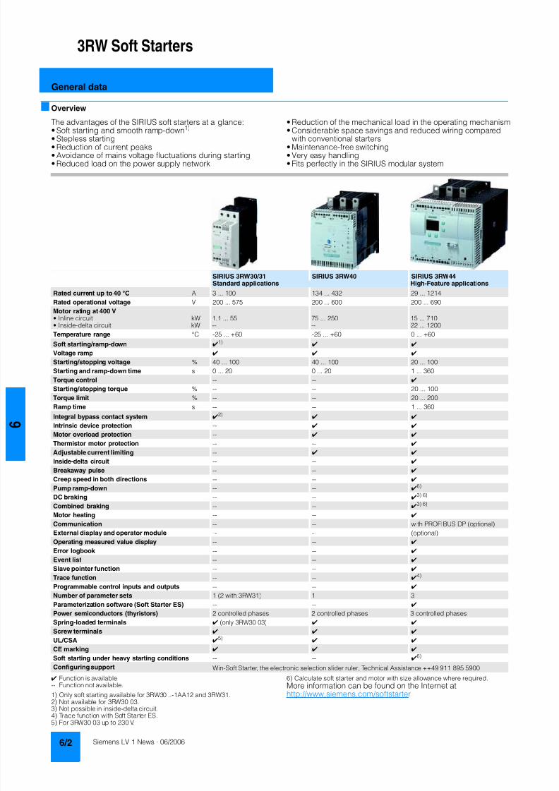
8122019 Arr Estado Solido
httpslidepdfcomreaderfullarr-estado-solido 640
3RW Soft Starters
General data
Overview
The advantages of the SIRIUS soft starters at a glancebull Soft starting and smooth ramp-down1)
bull Stepless startingbull Reduction of current peaksbull Avoidance of mains voltage fluctuations during startingbull Reduced load on the power supply network
bull Reduction of the mechanical load in the operating mechanismbull Considerable space savings and reduced wiring compared
with conventional startersbull Maintenance-free switchingbull Very easy handlingbull Fits perfectly in the SIRIUS modular system
Function is available
-- Function not available1) Only soft starting available for 3RW30 -1AA12 and 3RW312) Not available for 3RW30 033) Not possible in inside-delta circuit4) Trace function with Soft Starter ES5) For 3RW30 03 up to 230 V
6) Calculate soft starter and motor with size allowance where required
More information can be found on the Internet athttpwwwsiemenscomsoftstarter
SIRIUS 3RW3031 SIRIUS 3RW40 SIRIUS 3RW44Standard applications High-Feature applications
Rated current up to 40 degC A 3 100 134 432 29 1214
Rated operational voltage V 200 575 200 600 200 690
Motor rating at 400 Vbull Inline circuit kW 11 55 75 250 15 710bull Inside-delta circuit kW -- -- 22 1200
Temperature range degC -25 +60 -25 +60 0 +60
Soft startingramp-down 1)
Voltage ramp
Startingstopping voltage 40 100 40 100 20 100
Starting and ramp-down time s 0 20 0 20 1 360
Torque control -- --
Startingstopping torque -- -- 20 100
Torque limit -- -- 20 200
Ramp time s -- -- 1 360
Integral bypass contact system 2)
Intrinsic device protection --
Motor overload protection --
Thermistor motor protection -- --
Adjustable current limiting --
Inside-delta circuit -- --
Breakaway pulse -- --
Creep speed in both directions -- --
Pump ramp-down -- -- 6)
DC braking -- -- 3) 6)
Combined braking -- -- 3) 6)
Motor heating -- --
Communication -- -- with PROFIBUS DP (optional)
External display and operator module -- -- (optional)
Operating measured value display -- --
Error logbook -- --
Event list -- --
Slave pointer function -- --
Trace function -- -- 4)
Programmable control inputs and outputs -- --
Number of parameter sets 1 (2 with 3RW31) 1 3
Parameterization software (Soft Starter ES) -- --
Power semiconductors (thyristors) 2 controlled phases 2 controlled phases 3 controlled phases
Spring-loaded terminals (only 3RW30 03)
Screw terminals
ULCSA 5)
CE marking
Soft starting under heavy starting conditions -- -- 6)
Configuring support Win-Soft Starter the electronic selection slider ruler Technical Assistance ++49 911 895 5900
8122019 Arr Estado Solido
httpslidepdfcomreaderfullarr-estado-solido 740
3RW Soft Starters
3RW44for High-Feature applications
Overview
In addition to soft starting and soft ramp-down the solid-stateSIRIUS 3RW44 soft starters provide numerous functions for
higher-level requirements They cover a rating range up to710 kW (at 400 V) in the inline circuit and up to 1200 kW(at 400 V) in the inside-delta circuit
The SIRIUS 3RW44 soft starters are characterized by a compactdesign for space-saving and clearly arranged control cabinetlayouts For optimized motor starting and stopping the innova-tive SIRIUS 3RW44 soft starters are an attractive alternative withconsiderable savings potential compared to applications with afrequency converter The new torque control and adjustablecurrent limiting enable the High-Feature soft starters to be usedin nearly every conceivable task They guarantee the reliableavoidance of sudden torque applications and current peaksduring motor starting and stopping This creates savings poten-tial when calculating the size of the switchgear and when servic-ing the machinery installed Be it for inline circuits or inside-deltacircuits ndash the SIRIUS 3RW44 soft starter offers savings especiallyin terms of size and equipment costs
Combinations of various starting operating and ramp-downpossibilities ensure an optimum adaptation to the application-specific requirements Operating and commissioning can beperformed by means of the user-friendly keypad and a menu-prompted multi-line graphic display with background lightingThe optimized motor ramp-up and ramp-down can be effectedby means of just a few settings with a previously selectedlanguage Four-key operation and plain-text displays for eachmenu point guarantee full clarity at every moment of theparameterization and operation
Applicable standards
bull IEC 60947-4-2
bull ULCSA
Application
The SIRIUS 3RW44 solid-state soft starters are suitable for thetorque-controlled soft starting and smooth ramp-down as well as
braking of three-phase asynchronous motors
Application areas e g
bull Pumps
bull Ventilators
bull Compressors
bull Water transport
bull Conveying systems and lifts
bull Hydraulics
bull Machine tools
bull Mills
bull Saws
bull Breakers
bull Mixersbull Centrifuges
bull Industrial cooling and refrigerating systems
8122019 Arr Estado Solido
httpslidepdfcomreaderfullarr-estado-solido 840
3RW Soft Starters
3RW44for High-Feature applications
Selection and ordering data
1) 3RW44 2 3RW44 3 and 3RW44 4 soft starters with screw-typeterminals delivery time class (preferred type)
2) Control by way of the internal 24 V DC supply and direct control by meansof PLC possible
NoteSoft starter selection depends on the motors rated current
The 3RW44 solid-state soft starters are designed for normalstarting (class 10) (Inertia load of the overall operating mecha- nism JLoad lt 10 x JMotor starting current 350 x Ie for 20 s orsimilar load) For any other conditions of use the devices shouldbe selected using the Win-Soft Starter selection and simulationprogram See Technical Specifications for information aboutrated currents for ambient temperatures gt 40 degC and operatingfrequency
3RW44 27-1BC44 3RW44 36-6BC44 3RW44 47-6BC44 3RW44 58-6BC44
Ambient temperature 40 degC Ambient temperature 50 degC DT Order No Priceper PU
PU(UNITSET M)
PS PG Weightper PUapprox
Ratedopera-tionalcurrent I e
Rated output of three-phase inductionmotors for rated operational voltageU e
Ratedopera-tionalcurrent I e
Rated output of three-phaseinduction motors for ratedoperational voltage U e
230 V 400 V 500 V 690 V 1000 V 200 V 230 V 460 V 575 V
A kW kW kW kW kW A hp hp hp hp kg
Inline circuit rated operational voltage 200 460 V1)
29 55 15 -- -- -- 26 75 75 15 -- 3RW44 22-BC4 1 1 unit 131 490036 75 185 -- -- -- 32 10 10 20 -- 3RW44 23-BC4 1 1 unit 131 490047 11 22 -- -- -- 42 10 15 25 -- 3RW44 24-BC4 1 1 unit 131 4900
57 15 30 -- -- -- 51 15 15 30 -- 3RW44 25-BC4 1 1 unit 131 490077 185 37 -- -- -- 68 20 20 50 -- 3RW44 26-BC4 1 1 unit 131 490093 22 45 -- -- -- 82 25 25 60 -- 3RW44 27-BC4 1 1 unit 131 4900
Order No supplement for connection methods
bull With spring-loaded terminals 3bull With screw terminals 1
113 30 55 -- -- -- 100 30 30 75 -- B 3RW44 34-BC4 1 1 unit 131 7900134 37 75 -- -- -- 117 30 40 75 -- B 3RW44 35-BC4 1 1 unit 131 7900162 45 90 -- -- -- 145 40 50 100 -- B 3RW44 36-BC4 1 1 unit 131 7900
203 55 110 -- -- -- 180 50 60 125 -- B 3RW44 43-BC4 1 1 unit 131 10300250 75 132 -- -- -- 215 60 75 150 -- B 3RW44 44-BC4 1 1 unit 131 10300313 90 160 -- -- -- 280 75 100 200 -- B 3RW44 45-BC4 1 1 unit 131 10300
356 110 200 -- -- -- 315 100 125 250 -- B 3RW44 46-BC4 1 1 unit 131 10300432 132 250 -- -- -- 385 125 150 300 -- B 3RW44 47-BC4 1 1 unit 131 10300
551 160 315 -- -- -- 494 150 200 400 -- C 3RW44 53-BC4 1 1 unit 131 50000615 200 355 -- -- -- 551 150 200 450 -- C 3RW44 54-BC4 1 1 unit 131 50000693 200 400 -- -- -- 615 200 250 500 -- C 3RW44 55-BC4 1 1 unit 131 50000
780 250 450 -- -- -- 693 200 250 600 -- C 3RW44 56-BC4 1 1 unit 131 50000880 250 500 -- -- -- 780 250 300 700 -- C 3RW44 57-BC4 1 1 unit 131 50000970 315 560 -- -- -- 850 300 350 750 -- C 3RW44 58-BC4 1 1 unit 131 50000
Order No supplement for connection methods
bull With spring-loaded terminals 2bull With screw terminals 6
Order No supplement for the rated control supply voltage U s2)
bull 115 V AC 3bull 230 V AC 4
8122019 Arr Estado Solido
httpslidepdfcomreaderfullarr-estado-solido 940
3RW Soft Starters
3RW44for High-Feature applications
1) 3RW44 2 3RW44 3 and 3RW44 4 soft starters with screw-typeterminals delivery time class A
2) Control by way of the internal 24 V DC supply and direct control by meansof PLC possible
NoteSoft starter selection depends on the motors rated current
The 3RW44 solid-state soft starters are designed for normalstarting (class 10) (Inertia load of the overall operating mecha-nism J Load lt 10 x J Motor starting current 350 x I e for 20 s orsimilar load) For any other conditions of use the devices shouldbe selected using the Win-Soft Starter selection and simulationprogram See Technical Specifications for information aboutrated currents for ambient temperatures gt 40 degC and operating
frequency
Ambient temperature 40 degC Ambient temperature 50 degC DT Order No Priceper PU
PU(UNITSET M)
PS PG Weightper PUapprox
Ratedopera-
tionalcurrent I e
Rated output of three-phaseinduction motors for rated operational
voltage U e
Ratedopera-
tionalcurrent I e
Rated output of three-phaseinduction motors for rated
operational voltage U e
230 V 400 V 500 V 690 V 1000 V 200 V 230 V 460 V 575 V
A kW kW kW kW kW A hp hp hp hp kg
Inline circuit rated operational voltage 400 600 V1)
29 -- 15 185 -- -- 26 -- -- 15 20 A 3RW44 22-BC5 1 1 unit 131 490036 -- 185 22 -- -- 32 -- -- 20 25 A 3RW44 23-BC5 1 1 unit 131 490047 -- 22 30 -- -- 42 -- -- 25 30 A 3RW44 24-BC5 1 1 unit 131 4900
57 -- 30 37 -- -- 51 -- -- 30 40 A 3RW44 25-BC5 1 1 unit 131 490077 -- 37 45 -- -- 68 -- -- 50 50 A 3RW44 26-BC5 1 1 unit 131 490093 -- 45 55 -- -- 82 -- -- 60 75 A 3RW44 27-BC5 1 1 unit 131 4900
Order No supplement for connection methods
bull With spring-loaded terminals 3bull With screw terminals 1
113 -- 55 75 -- -- 100 -- -- 75 75 B 3RW44 34-BC5 1 1 unit 131 7900134 -- 75 90 -- -- 117 -- -- 75 100 B 3RW44 35-BC5 1 1 unit 131 7900
162 -- 90 110 -- -- 145 -- -- 100 125 B 3RW44 36-BC5 1 1 unit 131 7900
203 -- 110 132 -- -- 180 -- -- 125 150 B 3RW44 43-BC5 1 1 unit 131 10300250 -- 132 160 -- -- 215 -- -- 150 200 B 3RW44 44-BC5 1 1 unit 131 10300313 -- 160 200 -- -- 280 -- -- 200 250 B 3RW44 45-BC5 1 1 unit 131 10300
356 -- 200 250 -- -- 315 -- -- 250 300 B 3RW44 46-BC5 1 1 unit 131 10300432 -- 250 315 -- -- 385 -- -- 300 400 B 3RW44 47-BC5 1 1 unit 131 10300
551 -- 315 355 -- -- 494 -- -- 400 500 C 3RW44 53-BC5 1 1 unit 131 50000615 -- 355 400 -- -- 551 -- -- 450 600 C 3RW44 54-BC5 1 1 unit 131 50000693 -- 400 500 -- -- 615 -- -- 500 700 C 3RW44 55-BC5 1 1 unit 131 50000
780 -- 450 560 -- -- 693 -- -- 600 750 C 3RW44 56-BC5 1 1 unit 131 50000880 -- 500 630 -- -- 780 -- -- 700 850 C 3RW44 57-BC5 1 1 unit 131 50000970 -- 560 710 -- -- 850 -- -- 750 950 C 3RW44 58-BC5 1 1 unit 131 50000
Order No supplement for connection methods
bull With spring-loaded terminals 2bull With screw terminals 6
Order No supplement for the rated control supply voltage U s2)
bull 115 V AC 3bull 230 V AC 4
You can order this quantity or a multiple thereof
8122019 Arr Estado Solido
httpslidepdfcomreaderfullarr-estado-solido 1040
3RW Soft Starters
3RW44for High-Feature applications
1) Control by way of the internal 24 V DC supply and direct control by meansof PLC possible
NoteSoft starter selection depends on the motors rated current
The 3RW44 solid-state soft starters are designed for normalstarting (class 10) (Inertia load of the overall operating mecha- nism J Load lt 10 x J Motor starting current 350 x I e for 20 s orsimilar load) For any other conditions of use the devices shouldbe selected using the Win-Soft Starter selection and simulationprogram See Technical Specifications for information aboutrated currents for ambient temperatures gt 40 degC and operatingfrequency
Ambient temperature 40 degC Ambient temperature 50 degC DT Order No Priceper PU
PU(UNITSET M)
PS PG Weightper PUapprox
Ratedopera-
tionalcurrent I e
Rated output of three-phaseinduction motors for rated operational
voltage U e
Ratedopera-
tionalcurrent I e
Rated output of three-phaseinduction motors for rated
operational voltage U e
230 V 400 V 500 V 690 V 1000 V 200 V 230 V 460 V 575 V
A kW kW kW kW kW A hp hp hp hp kg
Inline circuit rated operational voltage 400 690 V
29 -- 15 185 30 -- 26 -- -- 15 20 B 3RW44 22-BC6 1 1 unit 131 490036 -- 185 22 37 -- 32 -- -- 20 25 B 3RW44 23-BC6 1 1 unit 131 490047 -- 22 30 45 -- 42 -- -- 25 30 B 3RW44 24-BC6 1 1 unit 131 4900
57 -- 30 37 55 -- 51 -- -- 30 40 B 3RW44 25-BC6 1 1 unit 131 490077 -- 37 45 75 -- 68 -- -- 50 50 B 3RW44 26-BC6 1 1 unit 131 490093 -- 45 55 90 -- 82 -- -- 60 75 B 3RW44 27-BC6 1 1 unit 131 4900
Order No supplement for connection methods
bull With spring-loaded terminals 3bull With screw terminals 1
113 -- 55 75 110 -- 100 -- -- 75 75 B 3RW44 34-BC6 1 1 unit 131 7900134 -- 75 90 132 -- 117 -- -- 75 100 B 3RW44 35-BC6 1 1 unit 131 7900
162 -- 90 110 160 -- 145 -- -- 100 125 B 3RW44 36-BC6 1 1 unit 131 7900
203 -- 110 132 200 -- 180 -- -- 125 150 B 3RW44 43-BC6 1 1 unit 131 10300250 -- 132 160 250 -- 215 -- -- 150 200 B 3RW44 44-BC6 1 1 unit 131 10300313 -- 160 200 315 -- 280 -- -- 200 250 B 3RW44 45-BC6 1 1 unit 131 10300
356 -- 200 250 355 -- 315 -- -- 250 300 B 3RW44 46-BC6 1 1 unit 131 10300432 -- 250 315 400 -- 385 -- -- 300 400 B 3RW44 47-BC6 1 1 unit 131 10300
551 -- 315 355 560 -- 494 -- -- 400 500 C 3RW44 53-BC6 1 1 unit 131 50000615 -- 355 400 630 -- 551 -- -- 450 600 C 3RW44 54-BC6 1 1 unit 131 50000693 -- 400 500 710 -- 615 -- -- 500 700 C 3RW44 55-BC6 1 1 unit 131 50000
780 -- 450 560 800 -- 693 -- -- 600 750 C 3RW44 56-BC6 1 1 unit 131 50000880 -- 500 630 900 -- 780 -- -- 700 850 C 3RW44 57-BC6 1 1 unit 131 50000970 -- 560 710 1000 -- 850 -- -- 750 950 C 3RW44 58-BC6 1 1 unit 131 50000
Order No supplement for connection methods
bull With spring-loaded terminals 2bull With screw terminals 6
Order No supplement for the rated control supply voltage U s1)
bull 115 V AC 3bull 230 V AC 4
8122019 Arr Estado Solido
httpslidepdfcomreaderfullarr-estado-solido 1140
3RW Soft Starters
3RW44for High-Feature applications
1) In the selection table the unit rated operational current I e refers to the
three-phase motors rated operational current in the inside-delta circuitThe actual current of the unit is approx 58 of this value
2) 3RW44 2 3RW44 3 and 3RW44 4 soft starters with screw-typeterminals delivery time class (preferred type)
3) Control by way of the internal 24 V DC supply and direct control by meansof PLC possible
NoteSoft starter selection depends on the motors rated current
The 3RW44 solid-state soft starters are designed for normalstarting (class 10) (Inertia load of the overall operatingmechanism JLoad lt 10 x JMotor starting current 350 x Ie for20 s or similar load) For any other conditions of use the devicesshould be selected using the Win-Soft Starter selection andsimulation program See Technical Specifications for informationabout rated currents for ambient temperatures gt 40 degC andoperating frequency
3RW44 27-1BC44 3RW44 36-6BC44 3RW44 47-6BC44 3RW44 58-6BC44
Ambient temperature 40 degC Ambient temperature 50 degC DT Order No Priceper PU
PU(UNITSET M)
PS PG Weightper PUapprox
Ratedopera-tionalcurrent I e
1)
Rated output of three-phase inductionmotors for rated operational voltageU e
Ratedopera-tionalcurrent I e
Rated output of three-phaseinduction motors for ratedoperational voltage U e
230 V 400 V 500 V 690 V 1000 V 200 V 230 V 460 V 575 V
A kW kW kW kW kW A hp hp hp hp kgInside-delta circuits rated operational voltage 200 460 V2)
50 15 22 -- -- -- 45 10 15 30 -- B 3RW44 22-BC4 1 1 unit 131 490062 185 30 -- -- -- 55 15 20 40 -- B 3RW44 23-BC4 1 1 unit 131 490081 22 45 -- -- -- 73 20 25 50 -- B 3RW44 24-BC4 1 1 unit 131 4900
99 30 55 -- -- -- 88 25 30 60 -- B 3RW44 25-BC4 1 1 unit 131 4900133 37 75 -- -- -- 118 30 40 75 -- B 3RW44 26-BC4 1 1 unit 131 4900161 45 90 -- -- -- 142 40 50 100 -- B 3RW44 27-BC4 1 1 unit 131 4900
Order No supplement for connection methods
bull With spring-loaded terminals 3bull With screw terminals 1
196 55 110 -- -- -- 173 50 60 125 -- B 3RW44 34-BC4 1 1 unit 131 7900232 75 132 -- -- -- 203 60 75 150 -- B 3RW44 35-BC4 1 1 unit 131 7900281 90 160 -- -- -- 251 75 100 200 -- B 3RW44 36-BC4 1 1 unit 131 7900
352 110 200 -- -- -- 312 100 125 250 -- B 3RW44 43-BC4 1 1 unit 131 10300433 132 250 -- -- -- 372 125 150 300 -- B 3RW44 44-BC4 1 1 unit 131 10300542 160 315 -- -- -- 485 150 200 400 -- B 3RW44 45-BC4 1 1 unit 131 10300
617 200 355 -- -- -- 546 150 200 450 -- B 3RW44 46-BC4 1 1 unit 131 10300748 250 400 -- -- -- 667 200 250 600 -- B 3RW44 47-BC4 1 1 unit 131 10300
954 315 560 -- -- -- 856 300 350 750 -- C 3RW44 53-BC4 1 1 unit 131 500001065 355 630 -- -- -- 954 350 400 850 -- C 3RW44 54-BC4 1 1 unit 131 500001200 400 710 -- -- -- 1065 350 450 950 -- C 3RW44 55-BC4 1 1 unit 131 50000
1351 450 800 -- -- -- 1200 450 500 1050 -- C 3RW44 56-BC4 1 1 unit 131 500001524 500 900 -- -- -- 1351 450 600 1200 -- C 3RW44 57-BC4 1 1 unit 131 500001680 560 1000 -- -- -- 1472 550 650 1300 -- C 3RW44 58-BC4 1 1 unit 131 50000
Order No supplement for connection methods
bull With spring-loaded terminals 2bull With screw terminals 6
Order No supplement for the rated control supply voltage U s3)
bull 115 V AC 3bull 230 V AC 4
You can order this quantity or a multiple thereof
8122019 Arr Estado Solido
httpslidepdfcomreaderfullarr-estado-solido 1240
3RW Soft Starters
3RW44for High-Feature applications
1) In the selection table the unit rated operational current I e refers to thethree-phase motors rated operational current in the inside-delta circuitThe actual current of the unit is approx 58 of this value
2) 3RW44 2 3RW44 3 and 3RW44 4 soft starters with screw-typeterminals delivery time class A
3) Control by way of the internal 24 V DC supply and direct control by meansof PLC possible
Accessories
NoteSoft starter selection depends on the motors rated current
The 3RW44 solid-state soft starters are designed for normalstarting (class 10) (Inertia load of the overall operatingmechanism J Load lt 10 x J Motor starting current 350 x I e for20 s or similar load) For any other conditions of use the devicesshould be selected using the Win-Soft Starter selection andsimulation program See Technical Specifications for informationabout rated currents for ambient temperatures gt 40 degC andoperating frequency
Ambient temperature 40 degC Ambient temperature 50 degC DT Order No Priceper PU
PU(UNITSET M)
PS PG Weightper PUapprox
Ratedopera-
tionalcurrent I e
1)
Rated output of three-phaseinduction motors for rated opera-
tional voltage U e
Ratedopera-
tionalcurrent I e
Rated output of three-phaseinduction motors for rated
operational voltage U e
230 V 400 V 500 V 690 V 1000 V 200 V 230 V 460 V 575 V
A kW kW kW kW kW A hp hp hp hp kg
Inside-delta circuits rated operational voltage 400 600 V2)
50 -- 22 30 -- -- 45 -- -- 30 40 B 3RW44 22-BC5 1 1 unit 131 490062 -- 30 37 -- -- 55 -- -- 40 50 B 3RW44 23-BC5 1 1 unit 131 490081 -- 45 45 -- -- 73 -- -- 50 60 B 3RW44 24-BC5 1 1 unit 131 4900
99 -- 55 55 -- -- 88 -- -- 60 75 B 3RW44 25-BC5 1 1 unit 131 4900133 -- 75 90 -- -- 118 -- -- 75 100 B 3RW44 26-BC5 1 1 unit 131 4900161 -- 90 110 -- -- 142 -- -- 100 125 B 3RW44 27-BC5 1 1 unit 131 4900
Order No supplement for connection methods
bull With spring-loaded terminals 3bull With screw terminals 1
196 -- 110 132 -- -- 173 -- -- 125 150 B 3RW44 34-BC5 1 1 unit 131 7900232 -- 132 160 -- -- 203 -- -- 150 200 B 3RW44 35-BC5 1 1 unit 131 7900
281 -- 160 200 -- -- 251 -- -- 200 250 B 3RW44 36-BC5 1 1 unit 131 7900
352 -- 200 250 -- -- 312 -- -- 250 300 B 3RW44 43-BC5 1 1 unit 131 10300433 -- 250 315 -- -- 372 -- -- 300 350 B 3RW44 44-BC5 1 1 unit 131 10300542 -- 315 355 -- -- 485 -- -- 400 500 B 3RW44 45-BC5 1 1 unit 131 10300
617 -- 355 450 -- -- 546 -- -- 450 600 B 3RW44 46-BC5 1 1 unit 131 10300748 -- 400 500 -- -- 667 -- -- 600 750 B 3RW44 47-BC5 1 1 unit 131 10300
954 -- 560 630 -- -- 856 -- -- 750 950 C 3RW44 53-BC5 1 1 unit 131 500001065 -- 630 710 -- -- 954 -- -- 850 1050 C 3RW44 54-BC5 1 1 unit 131 500001200 -- 710 800 -- -- 1065 -- -- 950 1200 C 3RW44 55-BC5 1 1 unit 131 50000
1351 -- 800 900 -- -- 1200 -- -- 1050 1350 C 3RW44 56-BC5 1 1 unit 131 500001524 -- 900 1000 -- -- 1351 -- -- 1200 1500 C 3RW44 57-BC5 1 1 unit 131 500001680 -- 1000 1200 -- -- 1472 -- -- 1300 1650 C 3RW44 58-BC5 1 1 unit 131 50000
Order No supplement for connection methods
bull With spring-loaded terminals 2bull With screw terminals 6
Order No supplement for the rated control supply voltage U s3)
bull 115 V AC 3bull 230 V AC 4
Forsoft starters Version DT Order No Priceper PU PU(UNITSET M)
PS PG Weightper PUapprox
Type kg
Soft Starter ES 2006 PC communication program
Soft Starter ES 2006 Smart
Parameterization and service software forSIRIUS 3RW44 soft starters for parameterizingthrough the system interface on the deviceExecutes on PCPG under Windows 2000XPwithout PC cableType of supply CD single license
3ZS1 313-1CC10-0YA0 1 1 unit 131 0230
3ZS1 313-1CC10-0YA0 Soft Starter ES 2006 Professional
Parameterization and service software forSIRIUS 3RW44 soft starters for parameterizingthrough the system interface on the device andPROFIBUS DP interface (PROFIBUS as optional commu-nication module necessary)Executes on PCPG under Windows 2000XPwithout PC cableType of supply CD single license
A 3ZS1 313-2CC10-0YA0 1 1 unit 131 0230
8122019 Arr Estado Solido
httpslidepdfcomreaderfullarr-estado-solido 1340
3RW Soft Starters
3RW44for High-Feature applications
Spare parts
Forsoft starters
Version DT Order No Priceper PU
PU(UNITSET M)
PS PG Weightper PUapprox
Type kg
PC cables
For PCPG communication with SIRIUS 3RW44soft starters
through the system interface for connecting tothe serial interface of the PCPG
B 3UF7 940-0AA00-0 1 1 unit 131 0150
Box terminal blocks for soft starters
Box terminal blocks
3RW44 2 Included in del ivery
3RW44 3 bull Up to 70 mm2 3RT19 55-4G 1 1 unit 101 0237
bull Up to 120 mm2 3RT19 56-4G 1 1 unit 101 0270
3RW44 3 bull Up to 240 mm2 3RT19 66-4G 1 1 unit 101 0676
PROFIBUS Communication moduleModule to be plugged into the soft starter to connect thesoft starter to the PROFIBUS net
A 3RW4 900-0KC00 1 1 unit 131 0320
External display and operation module
to show and operate the fonctions supplied by the softstarter via externally mounted display and operationmodule(for example in the cubicle door)
A 3RW4 900-0AC00 1 1 unit 131 0320
Connection cable
from serial interface of 3RW44 soft starter to external dis-play and operation modulebull Length 05 m flat B 3UF7 932-0AA00-0 1 1 unit 131 0020bull Length 05 m round A 3UF7 932-0BA00-0 1 1 unit 131 0050bull Length10 m round A 3UF7 937-0BA00-0 1 1 unit 131 0100bull Length25 m round A 3UF7 933-0BA00-0 1 1 unit 131 0150
Covers for soft starters
Terminal covers for box terminals
Additional touch protection to be fitted at the boxterminals (2 units required per device)
3RW44 2 and3RW44 3
3RT19 56-4EA2 1 1 unit 101 0028
3RW44 4 3RT19 66-4EA2 1 1 unit 101 0038
Terminal covers for cable lugs and busbarconnections
3RW44 2 and3RW44 3
3RT19 56-4EA1 1 1 unit 101 0067
3RW44 4 3RT19 66-4EA1 1 1 unit 101 0124
Forsoft starters
Version DT Order No Priceper PU
PU(UNITSET M)
PS PG Weightper PUapprox
Type kg
Fans
Fans
3RW44 2 and3RW44 3
115 VAC 3RW49 36-8VX30 1 1 unit 131 0300230 VAC 3RW49 36-8VX40 1 1 unit 131 0300
3RW44 4 115 V AC 3RW49 47-8VX30 1 1 unit 131 0500230 VAC 3RW49 47-8VX40 1 1 unit 131 0500
3RW44 5 115 V AC 3RW49 57-8VX30 1 1 unit 131 0800230 VAC 3RW49 57-8VX40 1 1 unit 131 0800
You can order this quantity or a multiple thereof
8122019 Arr Estado Solido
httpslidepdfcomreaderfullarr-estado-solido 1440
3RW Soft Starters
3RW44for High-Feature applications
Function
Equipped with modern ergonomic user prompting theSIRIUS 3RW44 soft starters can be commissioned quickly and
easily using a keypad and a menu-prompted multi-line displaywith background lighting Motor starting and deceleration areoptimized quickly easily and safely with just a few settings in aselectable language Four-key operation and plain-text displaysfor each menu point guarantee full clarity at every moment of theparameterization and operation Measurement values and oper-ating values as well as warning messages and fault indicationsare output continuously on the front panel during operation andwhen control voltage is applied An external display and opera-tor module can be connected by means of a connecting cableto the soft starter thus enabling active indications and the like tobe read directly from the control cabinet door
The SIRIUS 3RW44 soft starters are equipped with optimumfunctionality An integral bypass contact system reduces thepower loss of the soft starter during operation This reliablyprevents heating of the switchgear environment TheSIRIUS 3RW44 soft starters have internal intrinsic deviceprotection This prevents thermal overloading of the powersections thyristors eg due to unacceptably high closingoperations
Wiring work for installing an additional motor overload relay is nolonger needed as the SIRIUS 3RW44 soft starters perform thisfunction too In addition they offer adjustable trip classes and athermistor motor protection function As an option the thyristorscan also be protected by SITOR semi-conductor fuses fromshort-circuiting And even inrush current peaks are reliablyavoided thanks to adjustable current limiting
As a further option the SIRIUS 3RW44 soft starters can beupgraded with a PROFIBUS DP module Thanks to their commu-nication capability and their programmable control inputs andrelay outputs the SIRIUS 3RW44 soft starters can be very easily
and quickly integrated in higher-level controllersIn addition a creep speed function is available for positioningand setting jobs With this function the motor can be controlledin both directions of rotation with reduced torque and an adjust-able low speed
On the other hand the SIRIUS 3RW44 soft starters offer a newcombined DC braking function for the fast stopping of drivingloads
Highlights bull Soft starting with breakaway pulse torque control or voltage
ramp and adjustable torque or current limiting as well as anycombination of these depending on load type
bull Integrated bypass contact system to minimize dissipatedpower
bull Various setting options for the starting parameters such asstarting torque starting voltage ramp-up and ramp-downtime and much more in three separate parameter sets
bull Start-up detectionbull Inside-delta circuit for savings in terms of size and equipment
costsbull Various ramp-down modes selectable free ramp-down
torque-controlled pump stopping combined DC brakingbull Solid-state motor overload and intrinsic device protectionbull Thermistor motor protectionbull Keypad with a menu-controlled multi-line graphic display with
background lighting
bull Interface for communication with the PC for more accuratesetting of the parameters as well as for control and monitoringbull Simple adaptation to the motor feederbull Simple mounting and commissioningbull Display of operating states and fault signalsbull Connection to PROFIBUS with optional PROFIBUS DP modulebull External display and operator modulebull System voltages from 200 to 690 V 50 to 60 Hzbull Applicable up to 60 degC (derating from 40 degC)
8122019 Arr Estado Solido
httpslidepdfcomreaderfullarr-estado-solido 1540
3RW Soft Starters
3RW44for High-Feature applications
Technical specifications
Type 3RW44 -BC3 3RW44 -BC4Terminal
Control electronics
Rated valuesRated control supply voltage A1A2PE V 115 AC 230 ACbull Tolerance -15+10 -15+10Rated control supply current STANDBY mA 30 20
Rated control supply current ONbull 3RW44 2 mA 300 170bull 3RW44 3 mA 500 250bull 3RW44 4 mA 750 400bull 3RW44 5 mA 450 200
Maximum current (pickup bypass)bull 3RW44 2 mA 1000 500bull 3RW44 3 mA 2500 1250bull 3RW44 4 mA 6000 3000bull 3RW44 5 mA 4500 2500
Rated frequency Hz 50 60 50 60bull Tolerance plusmn10 plusmn10
Type 3RW44 Terminal Factory presetting
Control electronics
Control inputsInput 1 IN1 Start motor right parameter set 1Input 2 IN2 No actionInput 3 IN3 No actionInput 4 IN4 Trip reset
Supply L+L-bull Rated operational current mA Approx 10 per input to DIN 19240bull Rated operational voltage L+ Internal voltage 24 V DC from inter-
nal supply through terminal L+ toIN1 IN4 Maximum load at L+approx 55 mA
L- External voltage DC external voltage(to DIN19240) through terminals
L- and IN1 IN4(min 12 V DC max 30 V DC)
Thermistor motor protection inputInput T1T2 PTC type A or Thermoclick Deactivated
Relay outputs (floating auxiliary contacts)Output 1 1314 ON periodOutput 2 2324 No actionOutput 3 3334 No actionOutput 4 959698 Group fault
Switching capacity of the relay outputs230 VAC-15 A 3 at 240 V24 VDC-13 A 1 at 24 VProtection against overvoltages Protection by means of Varistor through relay contactShort-circuit protection 4 A gLgG operational class
6 A quick (fuse is not included in scope of supply)
Protective functions
Motor protection functionsTrips in the event of Thermal overloading of the motor
Trip class to IEC 60947-4-1 Class 510152030 10Phase failure sensitivity gt 40
Overload warning yesReset and recovery ManualAutomatic ManualReset option after tripping ManualAutomatic ManualRecovery time min 1 30 1
Device protection functionsTrips in the event of Thermal overloading of the thyristorsReset option after tripping ManualAutomatic ManualRecovery time min 05
8122019 Arr Estado Solido
httpslidepdfcomreaderfullarr-estado-solido 1640
3RW Soft Starters
3RW44for High-Feature applications
Type 3RW44 Factory presetting
Control times and parameters
Control timesClosing delay (with connected control voltage) ms lt 50Closing delay (automatic mode) ms lt 4000Recovery time (closing command in active ramp-down) ms lt 100
Mains failure bridging timeControl supply voltage ms 100
Mains failure response timeLoad current circuit ms 100
Reclosing lockout after overload tripMotor protection trip min 1 30 1Device protection trip s 30
Setting options for startingVoltage ramp for starting voltage 20 100 30Torque control for starting torque 20 100 50Torque control for limit torque 20 200 150
Starting time s 0 360 20Maximum starting time s 1 1000 DeactivatedCurrent limit value 125 550 450
Breakaway voltage 40 100 80Breakaway time s 0 2 DeactivatedMotor heat output 0 100 0
Creep mode LeftRight runningSpeed factor as function of rated speed (n = n rated factor) 3 21 7Creep torque (reference variable depends on the motor used but isalways smaller than the rated torque of the motor)
20 100 50
Setting options for ramp-downTorque control for stopping torque 10 100 10Ramp-down time s 0 360 10Dynamic braking torque 20 100 50DC braking torque 20 100 50
Operating indicationsTest voltageTest mains phasesReady to start
Start active
Motor runningRamp-down active
Warningserror signalsMains voltage missingLeading-edge phase error
Phase failurebull L1bull L2bull L3
Missing load phasebull T1bull T2bull T3
Failurebull Contact element 1 (thyristor)bull Contact element 2 (thyristor)bull Contact element 3 (thyristor)
Flash memory faulty
Supply voltagebull Below 75 bull Below 85 bull Over 110
Current unbalance exceededThermal motor model overload
Prewarning limit exceededbull Motor heatingbull Time-related trip reserve
Bypass elements defectiveMains voltage too high
Device not namedWrong naming versionCurrent range exceeded
Motor blocking ndash shutdownCurrent limit exceeded
Power section
bull Overheatedbull OvertemperatureEmergency active
8122019 Arr Estado Solido
httpslidepdfcomreaderfullarr-estado-solido 1740
3RW Soft Starters
3RW44for High-Feature applications
1) Parameter motor left possible only in conjunction with creep mode
Type 3RW44 Factory presetting
Control times and parameters
Warningserror signals (contd)Temperature sensorbull Overloadbull Open-circuitbull Short-circuit
Ground faultbull Detectedbull Shutdown
Connection abort in manual modeMax number of starts exceeded I e limit value overshootundershoot
Cooling timebull Motor activebull Switch block active
Heat sink sensorbull Open-circuitbull Short-circuit
Quick-stop functionSwitch block faulty I e class setting not permissible
Control inputsInput 1 Motor right parameter set 1Input 2 No actionInput 3 No actionInput 4 Trip reset
Parameterizing options for control inputs 1 4 No actionLocal manual modeEmergency startCreep speedQuick-stopTrip reset
Motor right parameter set 1Motor left parameter set 11) Motor right parameter set 2Motor left parameter set 21) Motor right parameter set 3Motor left parameter set 31)
Relay outputsOutput 1 ON periodOutput 2 No actionOutput 3 No actionOutput 4 Group fault
Parameterizing options for relay outputs 1 3 No actionPAA output 1PAA output 2
Input 1Input 2Input 3Input 4
Ramp-upOperationBypassRamp-downON periodCommand motor on
FanDC braking contactor
Group warningGroup faultBus faultDevice error
Power onReady to start
Motor temperature sensors Deactivated DeactivatedThermoclickPTC type A
8122019 Arr Estado Solido
httpslidepdfcomreaderfullarr-estado-solido 1840
3RW Soft Starters
3RW44for High-Feature applications
1) Current limit on soft starter set to 350 I M
2) For intermittent duty S4 with ON period = 70 T u = 40 degC stand-aloneinstallation vertical The quoted operating frequencies do not apply forautomatic mode
3) Maximum adjustable rated motor current I M dependent on CLASS setting
Type 3RW44 -BC4 3RW44 -BC5 3RW44 -BC6
Power electronics
Rated operational voltage for inline circuit V 200 460 AC 400 600 AC 400 690 AC
Tolerance -15+10 -15+10 -15+10Rated operational voltage for inside-delta circuit V 200 460 AC 400 600 AC 400 600 ACTolerance -15+10 -15+10 -15+10
Rated frequency Hz 50 60Tolerance plusmn10
Continuous operation at 40 degC ( of I e) 115
Minimum load ( of set motor current I M) 8
Maximum conductor length between soft starter and motor m 200
Permissible installation height m 5000 (derating from 1000 see characteristics) higher on request
Permissible mounting position
Permissible ambient temperatureOperation degC 0 +60 (derating from +40)Storage degC -25 +80
Degree of protection IP00
Type 3RW44 22 3RW44 23 3RW44 24 3RW44 25 3RW44 26 3RW44 27
Power electronics
Rated operational current I e 29 36 47 57 77 93
Load rating with rated operational current I ebull Acc to IEC and ULCSA for individual mounting
at 405060 degC AC-53a A 292623 363229 474237 575145 776859 938272
Smallest adjustable rated motor current I Mfor the motor overload protection
A 5 7 9 11 15 18
Power lossbull In operation after completed ramp-up with uninterrupted rated
operational current (40 degC) approx W 8 10 32 36 45 55bull During starting with current limit set to 350 I M (40 degC) W 400 470 600 725 940 1160
Permissible rated motor current and starts per hour
bull Normal starting (Class 5)- Rated motor current I M
1) starting time 5 s A 29 36 47 57 77 93- Starts per hour2) 1h 41 34 41 41 41 41
- Rated motor current I M1)3) starting time 10 s A 29 36 47 57 77 93
- Starts per hour2) 1h 20 15 20 20 20 20
bull Normal starting (Class 10)- Rated motor current I M
1) starting time 10 s A 29 36 47 57 77 93- Starts per hour2) 1h 20 15 20 20 20 20
- Rated motor current I M1)3) starting time 20 s A 29 36 47 57 77 93
- Starts per hour2) 1h 10 6 10 10 8 8
bull Normal starting (Class 15)- Rated motor current I M
1) starting time 15 s A 29 36 47 57 77 93- Starts per hour2) 1h 13 9 13 13 13 13
- Rated motor current I M1)3) starting time 30 s A 29 36 47 57 77 93
- Starts per hour2) 1h 6 4 6 6 6 6
bull For heavy starting (Class 20)- Rated motor current I M
1) starting time 20 s A 29 36 47 57 73 88- Starts per hour2) 1h 10 6 10 10 10 10
- Rated motor current I M1)3) starting time 40 s A 29 36 47 57 73 88
- Starts per hour2) 1h 4 2 4 5 18 08
bull For very heavy starting (Class 30)- Rated motor current I M
1) starting time 30 s A 29 36 44 57 65 77- Starts per hour2) 1h 6 4 6 6 6 6
- Rated motor current I M1)3) starting time 60 s A 29 36 44 57 65 77
- Starts per hour2) 1h 18 08 33 15 2 1
8122019 Arr Estado Solido
httpslidepdfcomreaderfullarr-estado-solido 1940
3RW Soft Starters
3RW44for High-Feature applications
1) Current limit on soft starter set to 350 I M
2) For intermittent duty S4 with ON period = 70 T u = 40 degC stand-aloneinstallation vertical The quoted operating frequencies do not apply forautomatic mode
3) Maximum adjustable rated motor current I M dependent on CLASS setting
Type 3RW44 34 3RW44 35 3RW44 36
Power electronics
Rated operational current I e 113 134 162
Load rating with rated operational current I ebull Acc to IEC and ULCSA for individual mounting AC-53a
- at 40 degC A 113 134 162- at 50 degC A 100 117 145- at 60 degC A 88 100 125
Smallest adjustable rated motor current I Mfor the motor overload protection
A 22 26 32
Power lossbull In operation after completed ramp-up with uninterrupted rated
operational current (40 degC) approx W 64 76 95bull During starting with current limit set to 350 I M (40 degC) W 1350 1700 2460
Permissible rated motor current and starts per hour
bull Normal starting (Class 5)- Rated motor current I M
1) starting time 5 s A 113 134 162- Starts per hour2) 1h 41 39 41
- Rated motor current I M1)3) starting time 10 s A 113 134 162
- Starts per hour2) 1h 20 15 20
bull Normal starting (Class 10)- Rated motor current I M
1) starting time 10 s A 113 134 162- Starts per hour2) 1h 20 15 20
- Rated motor current I M1)3) starting time 20 s A 113 134 162
- Starts per hour2) 1h 9 6 7
bull Normal starting (Class 15)- Rated motor current I M
1) starting time 15 s A 113 134 162- Starts per hour2) 1h 13 9 12
- Rated motor current I M1)3) starting time 30 s A 113 134 162
- Starts per hour2) 1h 6 6 1
bull For heavy starting (Class 20)- Rated motor current I M
1) starting time 20 s A 106 125 147- Starts per hour2) 1h 9 9 10
- Rated motor current I M1)3) starting time 40 s A 106 125 147
- Starts per hour2) 1h 15 2 1
bull For very heavy starting (Class 30)- Rated motor current I M
1) starting time 30 s A 91 110 120
- Starts per hour2) 1h 6 6 6- Rated motor current I M
1)3) starting time 60 s A 91 110 120- Starts per hour2) 1h 2 2 2
8122019 Arr Estado Solido
httpslidepdfcomreaderfullarr-estado-solido 2040
3RW Soft Starters
3RW44for High-Feature applications
1) Current limit on soft starter set to 350 I M
2) For intermittent duty S4 with ON period = 70 T u = 40 degC stand-aloneinstallation vertical The quoted operating frequencies do not apply forautomatic mode
3) Maximum adjustable rated motor current I M dependent on CLASS setting
Type 3RW44 43 3RW44 44 3RW44 45 3RW44 46 3RW44 47
Power electronics
Rated operational current I e 203 250 313 356 432
Load rating with rated operational current I ebull Acc to IEC and ULCSA for individual mounting AC-53a
- at 40 degC A 203 250 313 356 432- at 50 degC A 180 215 280 315 385- at 60 degC A 156 185 250 280 335
Smallest adjustable rated motor current I Mfor the motor overload protection
A 40 50 62 71 86
Power lossbull In operation after completed ramp-up with uninterrupted rated
operational current (40 degC) approx W 89 110 145 174 232bull During starting with current limit set to 350 I M (40 degC) W 3350 4000 4470 5350 5860
Permissible rated motor current and starts per hour
bull Normal starting (Class 5)- Rated motor current I M
1) starting time 5 s A 203 250 313 356 432- Starts per hour2) 1h 41 41 41 41 39
- Rated motor current I M1)3) starting time 10 s A 203 250 313 356 432
- Starts per hour2) 1h 20 20 19 17 16
bull Normal starting (Class 10)- Rated motor current I M
1) starting time 10 s A 203 250 313 356 432- Starts per hour2) 1h 20 20 19 17 16
- Rated motor current I M1)3) starting time 20 s A 203 250 313 356 432
- Starts per hour2) 1h 9 10 6 4 5
bull Normal starting (Class 15)- Rated motor current I M
1) starting time 15 s A 203 240 313 325 402- Starts per hour2) 1h 13 13 10 13 11
- Rated motor current I M1)3) starting time 30 s A 203 240 313 325 402
- Starts per hour2) 1h 3 6 1 2 1
bull For heavy starting (Class 20)- Rated motor current I M
1) starting time 20 s A 195 215 275 285 356- Starts per hour2) 1h 10 10 10 10 10
- Rated motor current I M1)3) starting time 40 s A 195 215 275 285 356
- Starts per hour2) 1h 1 5 1 3 1
bull For very heavy starting (Class 30)- Rated motor current I M
1) starting time 30 s A 162 180 220 240 285
- Starts per hour2) 1h 6 6 6 6 6- Rated motor current I M
1)3) starting time 60 s A 162 180 220 240 285- Starts per hour2) 1h 3 3 3 2 1
8122019 Arr Estado Solido
httpslidepdfcomreaderfullarr-estado-solido 2140
3RW Soft Starters
3RW44for High-Feature applications
1) Current limit on soft starter set to 350 I M
2) For intermittent duty S4 with ON period = 70 T u = 40 degC stand-aloneinstallation vertical The quoted operating frequencies do not apply forautomatic mode
3) Maximum adjustable rated motor current I M dependent on CLASS setting
Type 3RW44 53 3RW44 54 3RW44 55 3RW44 56 3RW44 57 3RW44 58
Power electronics
Rated operational current I e 551 615 693 780 880 970
Load rating with rated operational current I ebull Acc to IEC and ULCSA for individual mounting AC-53a
- at 40 degC A 551 615 693 780 880 970- at 50 degC A 494 551 615 693 780 850- at 60 degC A 438 489 551 615 693 760
Smallest adjustable rated motor current I Mfor the motor overload protection
A 110 123 138 156 176 194
Power lossbull In operation after completed ramp-up with uninterrupted rated
operational current (40 degC) approx W 159 186 220 214 250 270bull During starting with current limit set to 350 I M (40 degC) W 7020 8100 9500 11100 13100 15000
Permissible rated motor current and starts per hour
bull Normal starting (Class 5)- Rated motor current I M
1) starting time 5 s A 551 615 693 780 880 970- Starts per hour2) 1h 41 41 37 33 22 17
- Rated motor current I M1)3) starting time 10 s A 551 615 693 780 880 970
- Starts per hour2) 1h 20 20 16 13 8 5
bull Normal starting (Class 10)- Rated motor current I M
1) starting time 10 s A 551 615 693 780 880 970- Starts per hour2) 1h 20 20 16 13 8 5
- Rated motor current I M1)3) starting time 20 s A 551 615 693 780 880 970
- Starts per hour2) 1h 10 9 6 4 03 03
bull Normal starting (Class 15)- Rated motor current I M
1) starting time 15 s A 551 615 666 723 780 821- Starts per hour2) 1h 13 13 11 9 8 8
- Rated motor current I M1)3) starting time 30 s A 551 615 666 723 780 821
- Starts per hour2) 1h 6 4 3 1 04 05
bull For heavy starting (Class 20)- Rated motor current I M
1) starting time 20 s A 551 591 633 670 710 740- Starts per hour2) 1h 10 10 7 8 8 9
- Rated motor current I M1)3) starting time 40 s A 551 591 633 670 710 740
- Starts per hour2) 1h 4 2 1 1 04 1
bull For very heavy starting (Class 30)- Rated motor current I M
1) starting time 30 s A 500 525 551 575 600 630
- Starts per hour2) 1h 6 6 6 6 6 6- Rated motor current I M
1)3) starting time 60 s A 500 525 551 575 600 630- Starts per hour2) 1h 2 1 1 1 15 1
8122019 Arr Estado Solido
httpslidepdfcomreaderfullarr-estado-solido 2240
3RW Soft Starters
3RW44for High-Feature applications
1) When connecting cable lugs to DIN 46235 use 3RT19 56-4EA1 terminalcover for conductor cross-sections from 95 mmsup2 to ensure phase spacing
2) When connecting cable lugs to DIN 46234 the 3RT19 66-4EA1 terminalcover must be used for conductor cross-sections of 240 mmsup2 and more aswell as DIN 46235 for conductor cross-sections of 185 mmsup2 and more tokeep the phase clearance
Type 3RW44 2 3RW44 3 3RW44 4 3RW44 5
Conductor cross-sections
Screw
terminals
Main conductors
with box terminal 3RT19 55-4G (55 kW) 3RT19 66-4G
Front clampingpoint connected
bull Finely stranded with end sleeve mm2 16 70 70 240bull Finely stranded without end sleeve mm2 16 70 70 240bull Stranded mm2 16 70 95 300
bull Ribbon cable conductors(number x width x thickness)
mm min 3 x 9 x 08max 6 x 155 x 08
min 6 x 9 x 08max 20 x 24 x 05
bull AWG conductors solid or stranded AWG 6 20 30 600 kcmil
Rear clamping pointconnected
bull Finely stranded with end sleeve mm2 16 70 120 185bull Finely stranded without end sleeve mm2 16 70 120 185bull Stranded mm2 16 70 120 240
bull Ribbon cable conductors(number x width x thickness)
mm min 3 x 9 x 08max 6 x 155 x 08
min 6 x 9 x 08max 20 x 24 x 05
bull AWG conductors solid or stranded AWG 6 20 250 500 kcmil
Both clamping
points connected
bull Finely stranded with end sleeve mm2 max 1 x 50 1 x 70 min 2 x 50 max 2 x 185
bull Finely stranded without end sleeve mm2 max 1 x 50 1 x 70 min 2 x 50 max 2 x 185bull Stranded mm2 max 2 x 70 max 2 x 70 max 2 x 240
bull Ribbon cable conductors(number x width x thickness)
mm max 2 x (6 x 155 x 08) max 2 x (20 x 24 x 05)
bull AWG conductors solid or stranded AWG max 2 x 10 min 2 x 20max 2 x 500 kcmil
bull Terminal screws M10 (hexagon socket AF4) M12 (hexagon socket AF5)- Pickup torque 10 12 20 22
90 110 180 195
Screwterminals
Main conductors
with box terminal 3RT19 56-4G
Front or rear clamp-ing point connected
bull Finely stranded with end sleeve mm2 16 120bull Finely stranded without end sleeve mm2 16 120bull Stranded mm2 16 120
bull Ribbon cable conductors(number x width x thickness)
mm min 3 x 9 x 08max 6 x 155 x 08
bull AWG conductors solid or stranded AWG 6 250 kcmil
Both clampingpoints connected
bull Finely stranded with end sleeve mm2 max 1 x 95 1 x 120bull Finely stranded without end sleeve mm2 max 1 x 95 1 x 120bull Stranded mm2 max 2 x 120
bull Ribbon cable conductors(number x width x thickness)
mm max 2 x (10 x 155 x 08)
bull AWG conductors solid or stranded AWG max 2 x 30
Screwterminals
Main conductors
Without box terminalrail connection
bull Finely stranded with cable lug mm2 16 951) 50 2402) 50 2402)
bull Stranded with cable lug mm2 25 1201) 70 2402) 70 2402)
bull AWG conductors solid or stranded AWG 4 250 kcmil 20 500 kcmil 10 500 kcmil
bull Connecting bar (max width) mm 17 25 60
bull Terminal screws M8 x 25 (AF13) M10 x 30 (AF17) M12 x 40- Pickup torque NM 10 14 14 24 20 35lbin 89 124 124 210 177 310
8122019 Arr Estado Solido
httpslidepdfcomreaderfullarr-estado-solido 2340
3RW Soft Starters
3RW44for High-Feature applications
Soft starters Type 3RW44
Conductor cross-sections
Auxiliary conductors (1 or 2 conductors can be connected)
Screw terminals
bull Solid mm2 2 x 05 25bull Finely stranded with end sleeve mm2 2 x 05 15
bull AWG cables- Solid or stranded AWG 2 x 20 14- Finely stranded with end sleeve AWG 2 x 20 16
bull Terminal screws- Pickup torque NM 07 09
lbin 7 8
Spring-loaded terminals
bull Solid mm2 2 x 025 25bull Finely stranded with end sleeve mm2 2 x 025 15bull AWG conductors solid or stranded AWG 2 x 24 14
Standard Parameters
Electromagnetic compatibility acc to EN 60947-4-2
EMC interference immunityElectrostatic discharge (ESD) EN 61000-4-2 plusmn4 kV contact discharge plusmn8 kV air discharge
Electromagnetic RF fields EN 61000-4-3 Frequency range 80 1000 MHz with 80 at 1 kHzDegree of severity 3 10 Vm
Conducted RF interference EN 61000-4-6 Frequency range 150 kHz 80 MHz with 80 at 1 kHzInterference 10 V
RF voltages and RF currents on conductorsBurst EN 61000-4-4 plusmn2 kV5 kHzSurge EN 61000-4-5 plusmn1 kV line to line
plusmn2 kV line to ground
EMC interference emission
EMC interference field strength EN55011 Limit value of Class A at 30 1000 MHz
Radio interference voltage EN55011 Limit value of Class A at 015 30 MHz
Is an RI suppression filter necessary
Degree of noise suppression A (industrial applications) no
8122019 Arr Estado Solido
httpslidepdfcomreaderfullarr-estado-solido 2440
3RW Soft Starters
3RW44for High-Feature applications
Fuse assignment
The coordination type to which the motor feeder with soft starteris mounted depends on the application-specific requirements
Normally fuseless mounting (combination of motor starter pro-tector and soft starter) is sufficient If type 2 coordination is to befulfilled semiconductor fuses must be fitted in the motor feeder
1) The rated motor current must be considered when selecting the devices
2) The types of coordination are explained in more detail in theTechnical information LV 1 T under ndash Fuseless Load Feeders
Inline circuit fuseless version
Soft starters Motor starter protectorscircuit-breakers1)
Rated current 440 V +10 Rated currentG1 Q1Type A Type A
Type of coordination 12) 3RW44 22 3RW44 27 I q = 32 kA 3RW44 34 and 3RW44 35 I q = 16 kA 3RW44 36 3RW44 57 I q = 65 kA
3RW44 22 29 3RV10 42-4HA10 503RW44 23 36 3RV10 42-4JA10 633RW44 24 47 3RV10 42-4KA10 75
3RW44 25 57 3RV10 42-4LA10 903RW44 26 77 3RV10 42-4MA10 1003RW44 27 93 3RV10 42-4MA10 100
3RW44 34 113 3VL17 16-2DD36 1603RW44 35 134 3VL17 16-2DD36 1603RW44 36 162 3VL37 25-2DC36 250
3RW44 43 203 3VL47 31-3DC36 3153RW44 44 250 3VL47 31-3DC36 3153RW44 45 313 3VL47 40-3DC36 400
3RW44 46 356 3VL47 40-3DC36 4003RW44 47 432 3VL57 50-3DC36 500
3RW44 53 551 3VL67 80-3DE36 8003RW44 54 615 3VL67 80-3DE36 8003RW44 55 693 3VL67 80-3DE36 800
3RW44 56 780 3VL77 10-3AB36 10003RW44 57 880 3VL77 10-3AB36 10003RW44 58 970 3VL77 12-3AB36 1200
8122019 Arr Estado Solido
httpslidepdfcomreaderfullarr-estado-solido 2540
3RW Soft Starters
3RW44for High-Feature applications
1) If the ramp-down function Combined braking is selected no brakingcontactor is requiredIf the ramp-down function DC braking is selected a braking contactormust also be used (see table for type)For applications with large centrifugal masses (J Load gt J Motor) werecommend the function DC braking
2) Additional auxiliary relay K4LZXRT4A4T30(3RW44 soft starter with rated control supply voltage 230 V AC)LZXRT4A4S15(3RW44 soft starter with rated control supply voltage 115 V AC)
3) The types of coordination are explained in more detail in theTechnical information LV 1 T under ndash Fuseless Load Feeders
Inline circuit fused version (line protection only)
Soft starters Line protections Line contactorsup to 400 V
Braking contactors1)2)
Rated current 690 V +5 Rated current Size (optional) (for typical circuit see page 633)G1 F1 K1 K2 K3Type A Type A Type Type Type
Type of coordination 13) I q = 65 kA
3RW44 22 29 3NA3 820-6 50 00 3RT10 34 3RT15 26 --3RW44 23 36 3NA3 822-6 63 00 3RT10 35 3RT15 26 --
3RW44 24 47 3NA3 824-6 80 00 3RT10 36 3RT15 35 --3RW44 25 57 3NA3 830-6 100 00 3RT10 44 3RT15 35 --3RW44 26 77 3NA3 132-6 125 1 3RT10 45 3RT10 24 3RT10 353RW44 27 93 3NA3 136-6 160 1 3RT10 46 3RT10 25 3RT10 36
3RW44 34 113 3NA3 244-6 250 2 3RT10 54 3RT10 34 3RT10 443RW44 35 134 3NA3 244-6 250 2 3RT10 55 3RT10 36 3RT10 453RW44 36 162 3NA3 365-6 500 3 3RT10 56 3RT10 44 3RT10 45
3RW44 43 203 2 x 3NA3 354-6 2 x 355 3 3RT10 64 3RT10 44 3RT10 543RW44 44 250 2 x 3NA3 354-6 2 x 355 3 3RT10 65 3RT10 44 3RT10 553RW44 45 313 2 x 3NA3 365-6 2 x 500 3 3RT10 75 3RT10 54 3RT10 56
3RW44 46 356 2 x 3NA3 365-6 2 x 500 3 3RT10 75 3RT10 54 3RT10 563RW44 47 432 2 x 3NA3 365-6 2 x 500 3 3RT10 76 3RT10 55 3RT10 64
3RW44 53 551 2 x 3NA3 365-6 2 x 500 3 3TF68 44-0CM7 3TF68 44-0CM7 3TF68 44-0CM73RW44 54 615 2 x 3NA3 365-6 2 x 500 3 3TF68 44-0CM7 3TF68 44-0CM7 3TF68 44-0CM73RW44 55 693 2 x 3NA3 365-6 2 x 500 3 3TF69 44-0CM7 3TF69 44-0CM7 3TF69 44-0CM7
3RW44 56 780 2 x 3NA3 365-6 2 x 500 3 3TF69 44-0CM7 3TF69 44-0CM7 3TF69 44-0CM73RW44 57 880 2 x 3NA3 365-6 2 x 500 3 2 x 3TF69 44-0CM7 2 x 3TF69 44-0CM7 2 x 3TF69 44-0CM7
3RW44 58 970 3 x 3NA3 365-6 3 x 500 3
8122019 Arr Estado Solido
httpslidepdfcomreaderfullarr-estado-solido 2640
3RW Soft Starters
3RW44for High-Feature applications
1) If the ramp-down function Combined braking is selected no brakingcontactor is requiredIf the ramp-down function DC braking is selected a braking contactormust also be used (see table for type)For applications with large centrifugal masses (J Load gt J Motor) werecommend the function DC braking
2) Additional auxiliary relay K4LZXRT4A4T30(3RW44 soft starter with rated control supply voltage 230 V AC)LZXRT4A4S15(3RW44 soft starter with rated control supply voltage 115 V AC)
3) The types of coordination are explained in more detail in theTechnical information LV 1 T under ndash Fuseless Load Feeders
Inline circuit fused version with 3NE1 SITOR all-range fuse (semiconductor and line protection)
Soft starters All-range fuses Line contactors upto 400 V
Braking contactors1)2)
Ratedcurrent
Rated current Voltage Size (optional) (for typical circuit see page 633)
G1 Frsquo1 K1 K2 K3Type A Type A V Type Type Type
Type of coordination 23) I q = 65 kA
3RW44 22 29 3NE1 020-2 80 690 +5 00 3RT10 34 3RT15 26 --
3RW44 23 36 3NE1 020-2 80 690 +5 00 3RT10 35 3RT15 26 --3RW44 24 47 3NE1 021-2 100 690 +5 00 3RT10 36 3RT15 35 --
3RW44 25 57 3NE1 022-2 125 690 +5 00 3RT10 44 3RT15 35 --3RW44 26 77 3NE1 022-2 125 690 +5 00 3RT10 45 3RT10 24 3RT10 353RW44 27 93 3NE1 024-2 160 690 +5 1 3RT10 46 3RT10 25 3RT10 36
3RW44 34 113 3NE1 225-2 200 690 +5 1 3RT10 54 3RT10 34 3RT10 443RW44 35 134 3NE1 227-2 250 690 +5 1 3RT10 55 3RT10 36 3RT10 453RW44 36 162 3NE1 227-2 250 690 +5 1 3RT10 56 3RT10 44 3RT10 45
3RW44 43 203 3NE1 230-2 315 600 +10 1 3RT10 64 3RT10 44 3RT10 543RW44 44 250 3NE1 331-2 350 460 +10 2 3RT10 65 3RT10 44 3RT10 553RW44 45 313 3NE1 333-2 450 690 +5 2 3RT10 75 3RT10 54 3RT10 56
3RW44 46 356 3NE1 334-2 500 690 +5 2 3RT10 75 3RT10 54 3RT10 563RW44 47 432 3NE1 435-2 560 690 +5 3 3RT10 76 3RT10 55 3RT10 64
3RW44 53 551 2 x 3NE1 334-2 500 690 +10 2 3TF68 44-0CM7 3TF68 44-0CM7 3TF68 44-0CM73RW44 54 615 2 x 3NE1 334-2 500 690 +10 2 3TF68 44-0CM7 3TF68 44-0CM7 3TF68 44-0CM73RW44 55 693 2 x 3NE1 334-2 500 690 +10 2 3TF69 44-0CM7 3TF69 44-0CM7 3TF69 44-0CM7
3RW44 56 780 2 x 3NE1 435-2 560 690 +10 3 3TF69 44-0CM7 3TF69 44-0CM7 3TF69 44-0CM7
3RW44 57 880 2 x 3NE1 435-2 560 690 +10 3 2 x 3TF69 44-0CM7 2 x 3TF69 44-0CM7 2 x 3TF69 44-0CM73RW44 58 970 2 x 3NE1 435-2 560 690 +10 3
8122019 Arr Estado Solido
httpslidepdfcomreaderfullarr-estado-solido 2740
3RW Soft Starters
3RW44for High-Feature applications
1) If the ramp-down function Combined braking is selected no brakingcontactor is requiredIf the ramp-down function DC braking is selected a braking contactor
must also be used (see table for type)For applications with large centrifugal masses (J Load gt J Motor) werecommend the function DC braking
2) Additional auxiliary relay K4LZXRT4A4T30(3RW44 soft starter with rated control supply voltage 230 V AC)
LZXRT4A4S15(3RW44 soft starter with rated control supply voltage 115 V AC)
3) The types of coordination are explained in more detail in theTechnical information LV 1 T under ndash Fuseless Load Feeders
Inline circuit fused version with 3NE or 3NC SITOR semiconductor fuse(semiconductor protection by fuse lead and overload protection by circuit-breaker)
Soft starters Semiconductor fuses minimum Semiconductor fuses maximum Semiconductor fuses (cylinder)
Ratedcurrent
Rated current Size Rated current Size Rated current Size
G1 F3 F3 F3Type A Type A Type A Type A
Type of coordination 23) I q = 65 kA
3RW44 22 29 3NE4 120 80 0 3NE4 121 100 0 3NC2 280 80 22 x 58
3RW44 23 36 3NE4 121 100 0 3NE4 122 125 0 3NC2 200 100 22 x 583RW44 24 47 3NE4 121 100 0 3NE4 122 125 0 3NC2 200 100 22 x 58
3RW44 25 57 3NE4 122 125 0 3NE4 124 160 03RW44 26 77 3NE4 124 160 0 3NE4 124 160 03RW44 27 93 3NE3 224 160 1 3NE3 333 450 2
3RW44 34 113 3NE3 225 200 1 3NE3 335 560 23RW44 35 134 3NE3 225 200 1 3NE3 335 560 23RW44 36 162 3NE3 227 250 1 3NE3 333 450 2
3RW44 43 203 3NE3 230-0B 315 1 3NE3 333 450 23RW44 44 250 3NE3 230-0B 315 1 3NE3 333 450 23RW44 45 313 3NE3 233 450 1 3NE3 336 630 2
3RW44 46 356 3NE3 333 450 2 3NE3 336 630 23RW44 47 432 3NE3 335 560 2 3NE3 338-8 800 2
3RW44 53 551 2 x 3NE3 335 560 2 3 x 3NE3 334-0B 500 23RW44 54 615 2 x 3NE3 335 560 2 3 x 3NE3 334-0B 500 23RW44 55 693 2 x 3NE3 335 560 2 3 x 3NE3 334-0B 500 2
3RW44 56 780 2 x 3NE3 336 630 2 2 x 3NE3 340-8 900 2
3RW44 57 880 2 x 3NE3 336 630 2 2 x 3NE3 340-8 900 23RW44 58 970 2 x 3NE3 336 630 2 2 x 3NE3 340-8 900 2
Soft starters Line contactorsup to 400 V
Braking contactors1)2) Motor starter protectors circuit-breakers
Max line protection
Ratedcurrent
(optional) (for typical circuit see page 633) 440 V +10 Rated current 690 V +5 Rated current Size
G1 K1 Q1 F1Type A Type Type Type Type A Type A
Type of coordination 23) 3RW44 22 3RW44 27 I q = 32 kA 3RW44 34 and 3RW44 35 I q = 16 kA 3RW44 36 3RW44 57 I q = 65 kA
3RW44 22 29 3RT10 34 3RT15 26 -- 3RV10 41-4HA10 50 3NA3 820-6 50 003RW44 23 36 3RT10 35 3RT15 26 -- 3RV10 41-4JA10 63 3NA3 822-6 63 003RW44 24 47 3RT10 36 3RT15 35 -- 3RV10 41-4KA10 75 3NA3 824-6 80 00
3RW44 25 57 3RT10 44 3RT15 35 -- 3RV10 41-4LA10 90 3NA3 830-6 100 003RW44 26 77 3RT10 45 3RT10 24 3RT10 35 3RV10 41-4MA10 100 3NA3 132-6 125 13RW44 27 93 3RT10 46 3RT10 25 3RT10 36 3RV10 41-4MA10 100 3NA3 136-6 160 1
3RW44 34 113 3RT10 54 3RT10 34 3RT10 44 3VL17 16-1DD36 160 3NA3 244-6 250 2
3RW44 35 134 3RT10 55 3RT10 36 3RT10 45 3VL17 16-1DD36 160 3NA3 244-6 250 23RW44 36 162 3RT10 56 3RT10 44 3RT10 45 3VL37 25-1DC36 250 3NA3 365-6 500 3
3RW44 43 203 3RT10 64 3RT10 44 3RT10 54 3VL47 31-1DC36 315 2 x 3NA3 354-6 2 x 355 33RW44 44 250 3RT10 65 3RT10 44 3RT10 55 3VL47 31-1DC36 315 2 x 3NA3 354-6 2 x 355 33RW44 45 313 3RT10 75 3RT10 54 3RT10 56 3VL47 40-1DC36 400 2 x 3NA3 365-6 2 x 500 3
3RW44 46 356 3RT10 75 3RT10 54 3RT10 56 3VL47 40-1DC36 400 2 x 3NA3 365-6 2 x 500 33RW44 47 432 3RT10 76 3RT10 55 3RT10 64 3VL57 50-1DC36 500 2 x 3NA3 365-6 2 x 500 3
3RW44 53 551 3TF68 44-0CM7 3TF68 44-0CM7 3TF68 44-0CM7 3VL67 80-1AB36 800 2 x 3NA3 365-6 2 x 500 33RW44 54 615 3TF68 44-0CM7 3TF68 44-0CM7 3TF68 44-0CM7 3VL67 80-1AB36 800 2 x 3NA3 365-6 2 x 500 33RW44 55 693 3TF69 44-0CM7 3TF69 44-0CM7 3TF69 44-0CM7 3VL67 80-1AB36 800 2 x 3NA3 365-6 2 x 500 3
3RW44 56 780 3TF69 44-0CM7 3TF69 44-0CM7 3TF69 44-0CM7 3VL77 10-1AB36 1000 2 x 3NA3 365-6 2 x 500 33RW44 57 880 2 x
3TF69 44-0CM72 x3TF69 44-0CM7
2 x3TF69 44-0CM7
3VL77 10-1AB36 1000 2 x 3NA3 365-6 2 x 500 3
3RW44 58 970 3VL77 12-1AB36 1200 3 x 3NA3 365-6 3 x 500 3
8122019 Arr Estado Solido
httpslidepdfcomreaderfullarr-estado-solido 2840
3RW Soft Starters
3RW44for High-Feature applications
1) The types of coordination are explained in more detail in theTechnical information LV 1 T under ndash Fuseless Load FeedersThe type of coordination 2 only refers to soft starters not to feeder compo-nents ( I q = 65 kA)
Inside-delta circuit fused version with 3NE or 3NC SITOR fuses(semiconductor protection by fuse lead and overload protection by circuit-breaker)
Soft starters Semiconductor fuses minimum Semiconductor fuses maximum Semiconductor fuses (cylinder)
Ratedcurrent
Rated current Size Rated current Size Rated current Size
G1 F3 F3 F3Type A Type A Type A Type A
Type of coordination 21)
3RW44 22 50 3NE4 120 80 0 3NE4 121 100 0 3NC2 280 80 22 x 58
3RW44 23 62 3NE4 121 100 0 3NE4 122 125 0 3NC2 200 100 22 x 583RW44 24 81 3NE4 121 100 0 3NE4 122 125 0 3NC2 200 100 22 x 58
3RW44 25 99 3NE4 122 125 0 3NE4 124 160 03RW44 26 133 3NE4 124 160 0 3NE4 124 160 03RW44 27 161 3NE3 224 160 1 3NE3 333 450 2
3RW44 34 196 3NE3 225 200 1 3NE3 335 560 23RW44 35 232 3NE3 225 200 1 3NE3 335 560 23RW44 36 281 3NE3 227 250 1 3NE3 333 450 2
3RW44 43 352 3NE3 230-0B 315 1 3NE3 333 450 23RW44 44 433 3NE3 230-0B 315 1 3NE3 333 450 23RW44 45 542 3NE3 233 450 1 3NE3 336 630 2
3RW44 46 617 3NE3 333 450 2 3NE3 336 630 23RW44 47 748 3NE3 335 560 2 3NE3 338-8 800 2
3RW44 53 954 2 x 3NE3 335 560 2 3 x 3NE3 334-0B 500 23RW44 54 1065 2 x 3NE3 335 560 2 3 x 3NE3 334-0B 500 23RW44 55 1200 2 x 3NE3 335 560 2 3 x 3NE3 334-0B 500 2
3RW44 56 1351 2 x 3NE3 336 630 2 2 x 3NE3 340-8 900 2
3RW44 57 1524 2 x 3NE3 336 630 2 3 x 3NE3 340-8 900 23RW44 58 1680 2 x 3NE3 336 630 2 3 x 3NE3 340-8 900 2
Soft starters Line contactorsup to 400 V
Motor starter protectors cirduit-breakers
Line protections
Ratedcurrent
(optional) 440 V +10 Rated current 690 V +5 Rated current Size
G1 K1 Q1 F1Type A Type Type A Type A
Type of coordination 21)
3RW44 22 50 3RT10 36-1AP04 3RV10 4-4KA10 75 3NA3 824-6 80 003RW44 23 62 3RT10 44-1AP04 3RV10 4-4LA10 90 3NA3 830-6 100 003RW44 24 81 3RT10 46-1AP04 3RV10 4-4MA10 100 3NA3 132-6 125 1
3RW44 25 99 3RT10 54-1AP36 3VL27 16-DC36 160 3NA3 136-6 160 13RW44 26 133 3RT10 55-6AP36 3VL27 16-DC36 160 3NA3 240-6 200 23RW44 27 161 3RT10 56-6AP36 3VL37 20-DC36 200 3NA3 244-6 250 2
3RW44 34 196 3RT10 64-6AP36 3VL37 25-DC36 250 3NA3 360-6 400 3
3RW44 35 232 3RT10 65-6AP36 3VL47 31-DC36 315 3NA3 360-6 400 33RW44 36 281 3RT10 66-6AP36 3VL47 40-DC36 400 2 x 3NA3 360-6 2 x 400 3
3RW44 43 352 3RT10 75-6AP36 3VL47 40-DC36 400 2 x 3NA3 365-6 2 x 500 33RW44 44 433 3RT10 76-6AP36 3VL57 50-DC36 500 2 x 3NA3 365-6 2 x 500 33RW44 45 542 3TF68 44-0CM7 3VL57 63-DC36 800 3 x 3NA3 365-6 3 x 500 3
3RW44 46 617 3TF68 44-0CM7 3VL67 80-AB36 800 3 x 3NA3 365-6 3 x 500 33RW44 47 748 3TF69 3VL67 80-AB36 1000 3 x 3NA3 365-6 3 x 500 3
3RW44 53 954 2 x 3TF68 44-0CM7 3VL77 10-AB36 1000 3 x 3NA3 365-6 3 x 500 33RW44 54 1065 2 x 3TF68 44-0CM7 3VL77 12-AB36 1250 3 x 3NA3 365-6 3 x 500 33RW44 55 1200 2 x 3TF69 44-0CM7 3VL87 16-AB36 1600 3 x 3NA3 365-6 3 x 500 3
3RW44 56 1351 2 x 3TF69 44-0CM7 3VL87 16-AB36 1600 3 x 3NA3 372 3 x 630 33RW44 57 1524 2 x 3TF69 44-0CM7 3VL87 16-AB36 1600 3 x 3NA3 372 3 x 630 33RW44 58 1680 3WL12 20 2000 2 x 3NA3 480 2 x 1000 4
8122019 Arr Estado Solido
httpslidepdfcomreaderfullarr-estado-solido 2940
3RW Soft Starters
3RW44for High-Feature applications
Characteristic curves
Motor protection tripping characteristics for 3RW44(with symmetry)
Admissible mounting height
The admissible operational voltage is reduced to 460 V with a mountingheight of more than 2000 m
Motor protection characteristics for 3RW44(with phase unbalance)
e
2 4 6 101
Class 10 Class 15 Class 20
100
101
102
103
2
4
6
2
4
6
2
4
6
Class 5 Class 30
N S B 0
_ 0 1 5 0 0 a
[ s ]
x
T r i p p i n g t i m e
85
105
70
75
80
90
95
100
N S B 0
_ 0 1 7 0 4
0 1000 2000 3000 4000 5000 O p e r
a t i o n a
l r a
t e d c u r r e n
t I
i n
Mounting height in m
e
e
1001
Class 10 Class 15 Class 20
100
101
102
103
2
4
6
2
4
6
2
4
6
Class 5 Class 30
N S B 0
_ 0 1 7 0 6
[ s ]
x10
T r i p p
i n g
t i m e
8122019 Arr Estado Solido
httpslidepdfcomreaderfullarr-estado-solido 3040
3RW Soft Starters
3RW44for High-Feature applications
More information
Application examples for normal starting (Class 10)
Application examples for heavy starting (Class 20)
Application examples for very heavy starting (Class 30)
NoteThese tables present sample setting values and device sizesThey are intended only for the purposes of information and arenot binding The setting values depend on the application inquestion and must be optimized during commissioningThe soft starter dimensions should be checked where necessarywith the Win-Soft Starter software or with the help ofTechnical Assistance
Normal starting Class 10 (up to 20 s with 350 I n motor)The soft starter rating can be selected to be as high as the rating of the motor used
Application Conveyor belts Roller conveyors Compressors Small ventilators Pumps Hydraulic pumps
Starting parameters
bull Voltage ramp and currentlimiting- Starting voltage 70 60 50 30 30 30- Starting time s 10 10 10 10 10 10- Current limit value Deactivated Deactivated 4 x I M 4 x I M Deactivated Deactivated
bull Torque ramp- Starting torque 60 50 40 20 10 10- End torque 150 150 150 150 150 150- Starting time 10 10 10 10 10 10
bull Breakaway pulse Deactivated (0 ms) Deactivated (0 ms) Deactivated (0 ms) Deactivated (0 ms) Deactivated (0 ms) Deactivated (0 ms)
Ramp-down mode Smoothramp-down
Smoothramp-down
Free ramp-down Free ramp-down Pump ramp-down Free ramp-down
Heavy starting Class 20 (up to 40 s with 350 I n motor)The soft starter has to be selected one rating class higher than the motor used
Application Stirrers Centrifuges Milling machines
Starting parameters
bull Voltage ramp and currentlimiting- Starting voltage 30 30 30- Starting time s 30 30 30- Current limit value 4 x I M 4 x I M 4 x I M
bull Torque ramp- Starting torque 30 30 30- End torque 150 150 150- Starting time 30 30 30
bull Breakaway pulse Deactivated (0 ms) Deactivated (0 ms) Deactivated (0 ms)
Ramp-down mode Free ramp-down Free ramp-down Free ramp-down or DC braking
Very heavy starting Class 30 (up to 60 s with 350 I n motor)The soft starter has to be selected two rating classes higher than the motor used
Application Large ventilators Mills Breakers Circular sawbandsaws
Starting parameters
bull Voltage ramp and currentlimiting- Starting voltage 30 50 50 30- Starting time s 60 60 60 60- Current limit value 4 x I M 4 x I M 4 x I M 4 x I M
bull Torque ramp- Starting torque 20 50 50 20- End torque 150 150 150 150- Starting time 60 60 60 60
bull Breakaway pulse Deactivated (0 ms) 80 300 ms 80 300 ms Deactivated (0 ms)
Ramp-down mode Free ramp-down Free ramp-down Free ramp-down Free ramp-down
8122019 Arr Estado Solido
httpslidepdfcomreaderfullarr-estado-solido 3140
3RW Soft Starters
3RW44for High-Feature applications
Circuit concept
The SIRIUS 3RW44 soft starters can be operated in two differenttypes of circuit
bull Inline circuitThe controls for isolating and protecting the motor are simplyconnected in series with the soft starter The motor isconnected to the soft starter with three leads
bull Inside-delta circuitThe wiring is similar to that of wye-delta starters The phases ofthe soft starter are connected in series with the individual motorwindings The soft starter then only has to carry the phasecurrent amounting to about 58 of the rated motor current(conductor current)
Comparison of the types of circuit
Inline circuitRated current I e corresponds to the rated motor current I n3 leads to the motor
Inside-delta circuit
Rated current I e corresponds to approx 58 of the rated motorcurrent I n6 leads to the motor (as with wye-delta starters)
Which circuit
Using the inline circuit involves the lowest wiring complexityIf the soft starter to motor connections are long this contactsequence is preferableWith the inside-delta circuit there is double the wiring complexitybut a smaller size of device can be used at the same rating
Thanks to choosing the operational mode between the inline cir-cuit and inside-delta circuit the most favorable solution can al-ways be chosen
The braking function is possible only in the inline circuit
Configuration
The 3RW44 solid-state soft starters are designed for normalstarting In case of heavy starting or increased starting
frequency a larger device must be selectedFor long starting times it is recommended to have a PTC ther-mistor detector in the motor This also applies for the ramp-downmodes smooth ramp-down pump ramp-down and DC brakingbecause during the ramp-down time in these modes an addi-tional current loading applies in contrast to free ramp-down
In the motor feeder between the SIRIUS 3RW soft starter and themotor no capacitive elements are permitted (eg no reactive-power compensation equipment) In addition neither staticsystems for reactive-power compensation nor dynamic PFC(Power Factor Correction) must be operated in parallel duringstarting and ramp-down of the soft starter This is important toprevent faults arising on the compensation equipment andor thesoft starter
All elements of the main circuit (such as fuses and controls)
should be dimensioned for direct starting following the localshort-circuit conditions Fuses switching devices and overloadrelays must be ordered separately
The harmonic component load for starting currents must betaken into consideration for the selection of motor starterprotectors (selection of release)
NoteWhen switching on three-phase current motors voltage dropsnormally will occur with all types of starters (direct starters star- delta starters soft starters) On principle the feeding transformermust be configured such that when starting the motor thevoltage drop must occur within the admissible tolerance Whenthe feeding transformer is designed quite scarce the control vol- tage (being independent of the main voltage) should be sup- plied with a separate circuit in order to prevent the soft starterfrom switching off
Serial PC interface PROFIBUS DP communication moduleand parameterizing and operating software Soft Starter ES
The solid-state 3RW44 soft starters have a PC interface forcommunicating with the Soft Starter ES 2006 Smart software orto be connected to an external operating and monitoring mod-ule When using the optional communication module PROFIBUSthe 3RW44 soft starter can be connected to the PROFIBUS netand can communicate via GSD file or software Soft Starter ES2006 Professional
Manual for SIRIUS 3RW44
Besides containing all important information on planning com-missioning and servicing the manual also contains suggestedcircuits and the technical specifications for all devices
Win-Soft Starter selection and simulation program
With this software you can simulate and select all Siemens softstarters taking into account various parameters such as mainsproperties motor and load data and special applicationrequirements
The software is a valuable tool which makes complicatedlengthy manual calculations for determining the required softstarters superfluous
You can order the CD-ROM under the following order numberOrder No E20001-D1020-P302-V2-7400
More information can be found on the Internet athttpwwwsiemenscomsoftstarter
8122019 Arr Estado Solido
httpslidepdfcomreaderfullarr-estado-solido 3240
3RW Soft Starters
3RW44for High-Feature applications
SIRIUS soft starter training course (SD-SIRIUSO)
Siemens offers a 2-day training course on the SIRIUS solid-statesoft starters to keep customers and own personnel up-to-date on
configuring commissioning and servicing issuesPlease direct enquiries and applications to
AampD PT 4 (Trainings-Center Erlangen)Werner-von-Siemens-Str 65D-91052 ErlangenTelefon ++49 9131 729262Telefax ++49 9131 728172sibrainindustrysiemenscomhttp wwwsiemenscomsitrain
8122019 Arr Estado Solido
httpslidepdfcomreaderfullarr-estado-solido 3340
3RW Soft Starters
Project planning aids
Dimensional drawings
3RW44 2 3RW44 3 and 3RW44 4 for High-Feature applications
TypeDimension(mm)
a b c d e f g h I k l m n o p q
3RW44 2 180 170 37 11 167 100 240 270 180 148 75 153 7 184 66 M6 10 Nm
3RW44 3 180 170 37 17 167 100 240 270 180 148 75 153 7 198 9 M6 10 Nm
3RW44 4 210 210 48 25 190 140 269 298 205 166 16 166 9 230 11 M8 15 Nm
8122019 Arr Estado Solido
httpslidepdfcomreaderfullarr-estado-solido 3440
3RW Soft Starters
Project planning aids
3RW44 5 for High-Feature applications
147
173
195
118
N S B 0_
0 1 6 5 3
261
290
249
162
152
6 2 3
1 0 5
2 5 3
1 6 5
76
44
470
510
1
5 5
2
0Oslash14 40
6 3 8 5
5 9 0
8122019 Arr Estado Solido
httpslidepdfcomreaderfullarr-estado-solido 3540
3RW Soft Starters
Project planning aids
Schematics
1) Permissible values for main and control voltagesee Technical Specifications
3RW44 connection examples for main and control circuits
Main circuit Control circuitPossibility 1a Possibility 1Inline circuit with circuit-breaker and SITOR fuse(semiconductor protection only)
Control by pushbutton
Main circuit
Possibility 1b Possibility 1cInline circuit with full-rangeprotection (line andsemiconductor protection)
Inline circuit with line andSITOR fuse(semiconductor protection only)
Q1
L3L2L1
G1
F3
T1 T2 T3
M1
N S B 0_
0 1 4 9 0 a
L1 L2 L3
V1U1 W1
MPE 3~
3NPE 400 V AC 50 Hz
(optionalsemiconductorprotection fuse)
13 14 23 24 33 34 95 9896 +
T1 T2IN4IN3IN2IN1L-L+A1
A2
NPE
PE
G1
F2
NSB0_01494a
S t a r t
S 2
R e s e t S
3
StopS1
L1
On periodGrouperror
N o a c t i o n
N o a c t i o n
Noaction
PTC type Aor
Thermoclick
Noaction
1NPE 230 V AC 50 Hz
M o t o r o
n r i g h t
P S
1
1)
8122019 Arr Estado Solido
httpslidepdfcomreaderfullarr-estado-solido 3640
3RW Soft Starters
Project planning aids
1) Permissible values for main and control voltagesee Technical Specifications
2) Caution Risk of restartingThe start command (eg from the PLC) must be reset prior to a resetcommand because a new automatic restart will take place automaticallyif a start command is active after the reset command This appliesespecially in case of motor protection trippingFor safety reasons we recommend incorporating the group error output(terminals 95 and 96) in the controller
Main circuit Control circuit
Possibility 2 Possibility 2Inline circuit with main contactor Control of a main contactor and control by means of PLC
Q1
L3L2L1
G1
K1
F3
L1 L2 L3
T1 T2 T3
M1
N S B 0_
0 1 4 9 5 a
V1U1 W1
MPE 3~
1)
(optionalsemiconductorprotection)
(optional linecontactor if floatingswitching of themotor is planned)
3NPE 400 V AC 50 Hz
13 14 23 24 33 34 95 9896+
T1 T2IN4IN3IN2IN1L-L+A1
A2
NPE
PE
G1
K1NSB0_01496a
F2+24 V DC
M
L1 1NPE AC 230 V 50 Hz1)
Switch-on duration
M o t o r r i g h t
T r i p R e s e t
PLC outputs PLC inputs
N o a c t i o n
N o a c t i o n
No action No action
Group error
PTC type A Thermoclick
(optional line contactorif floating switchingof the motor is planned)
P S 1
ResetStart 2)
8122019 Arr Estado Solido
httpslidepdfcomreaderfullarr-estado-solido 3740
3RW Soft Starters
Project planning aids
1) Permissible values for main and control voltagesee Technical Specifications
2) Caution Risk of restartingThe start command (eg from the PLC) must be reset prior to a resetcommand because a new automatic restart will take place automaticallyif a start command is active after the reset command This applies espe-cially in case of motor protection trippingFor safety reasons we recommend incorporating the group error output(terminals 95 and 96) in the controller
3) If the ramp-down function Combined braking is selected no brakingcontactor is requiredIf the ramp-down function DC braking is selected a braking contactormust be used in addition Type see Fuse Coordination (inline circuit) onpages 621 to 623For applications with large centrifugal masses (J Load gt J Motor) werecommend the function DC brakingThe output 2 must be switched over to DC braking contactor
4) Auxiliary relay K4 egLZXRT4A4T30 (230 V AC rated control supply voltage)LZXRT4A4S15 (115 V AC rated control supply voltage)
Main circuit Control circuit
Possibility 3a Possibility 3aInline circuit with ramp-down function DC braking3)
(for device types 3RW44 22 to 3RW44 25)Control of the braking contactor3)
Main circuit Control circuit
Possibility 3b Possibility 3bInline circuit with ramp-down function DC braking3)
(for device types 3RW44 26 to 3RW44 47)Control of the braking contactor3)
Q1
L3L2
G1
F3
T1 T2 T3
M1
N S B 0_
0 1 5 0 1 a
L1 L2 L3
V1U1 W1
M
K2 K2 K2
PE 3~
1)
2
(optionalsemi-conductorprotection)
L1 3NPE 400 V AC 50 Hz
13 14 23 24 33 34 95 9896 +
T1 T2IN4IN3IN2IN1L-L+A1
A2
NPE
PEG1
K2NSB0_01502
R e s e t
M Start Reset
+24 V DC
K2
F2
1)
2)
No action Group error
N o a c t i o n
N o a c t i o n
On period
PLC output
PTC type Aor
Thermoclick
L1 1NPE 230 V AC 50 Hz
DC braking contactor 3)
K2 K33 3
G1
F3
T1 T2 T3
M1
N S B 0_
0 1
5 0 3 a
L1 L2 L3
V1U1 W1
MPE 3~
Q1
L3L2
1)
(optionalsemi-conductorprotection)
L1 3NPE 400 V AC 50 Hz
13 14 23 24 33 34 95 9896 +
T1 T2IN4IN3IN2IN1L-L+A1
A2
NPE
PE
G1
K4
NSB0_01504
R e s e t
K4 K4
K3 K2
K2 K3
+24 V DC
M Start Reset
F2
1)
2)
4)
PLC output
No action Group error
N o a c t i o n
N o a c t i o n
ON period
PTC type Aor
Thermoclick
M o t o r o n r i g h t
L1 1NPE 230 V AC 50 Hz
DC braking contactor 3)
8122019 Arr Estado Solido
httpslidepdfcomreaderfullarr-estado-solido 3840
3RW Soft Starters
Notes
1) Permissible values for main and control voltagesee Technical Specifications
2) Caution Risk of restartingThe start command (eg from the PLC) must be reset prior to a resetcommand because a new automatic restart will take place automaticallyif a start command is active after the reset command This appliesespecially in case of motor protection trippingFor safety reasons we recommend incorporating the group error output(terminals 95 and 96) in the controller
Main circuit Control circuit
Possibility 4a Possibility 4b Possibility 4Inside-delta circuit Change of direction of rotation for
inside-delta circuitControl by means of PLC
13 14 23 24 33 34 95 9896+
T1 T2IN4IN3IN2IN1L-L+A1
A2
NPE
PEG1
NSB0_01498a
+24 V DC
M
F2
L1 1NPE AC 230 V 50 Hz1)
2)
R e s e t
Switch-onduration
No action
Group error
N o a c t i o n
N o a c t i o n
No action
PTC type A orThermoclick
M o t o r r i g h t
PLC outputs PLC inputs
Start Reset
7
8122019 Arr Estado Solido
httpslidepdfcomreaderfullarr-estado-solido 3940
Appendix
Conditions of sale and delivery
Terms and Conditions of Sale and Delivery
By using this catalog you can acquire hardware and softwareproducts described therein from the Siemens AG subject to the
following terms Please note The scope the quality and the con-ditions for supplies and services including software productsby any Siemens entity having a registered office outside of Ger-many shall be subject exclusively to the General Terms andConditions of the respective Siemens entity
For customers with a seat or registered office in theFederal Republic of Germany
The bdquoGeneral Terms of Paymentldquo as well as the bdquoGeneral Condi-tions for the Supply of Products and Services of the Electricaland Electronics Industryldquo shall apply
For software products the bdquoGeneral License Conditions for Soft-ware Products for Automation and Drives for Customers with aSeat or registered Office in Germanyldquo shall apply
For customers with a seat or registered office outside of
Germany The bdquoGeneral Terms of Paymentldquo as well as the bdquoGeneral Condi-tions for Supplies of Siemens Automation and Drives for Cus-tomers with a Seat or registered Office outside of Germanyldquo shallapply
For software products the bdquoGeneral License Conditions for Soft-ware Products for Automation and Drives for Customers with aSeat or registered Office outside of Germanyldquo shall apply
General
The prices are in 991404 (Euro) ex works exclusive packaging
The sales tax (value added tax) is not included in the pricesIt shall be debited separately at the respective rate according tothe applicable legal regulations
In addition to the prices of products which include silver plump
aluminum andor copper surcharges may be calculated if therespective limits of the notes are exceeded The respective note(eg source German newspaper bdquoHandesblattldquo in categorybdquodeutsche Edelmetalleldquo and bdquoMetallverarbeiterldquo) for silver (bdquover-arbeitetes Silberldquo) plump (bdquoBlei in Kabelnldquo) aluminum (bdquoAlumin-ium in Kabelnldquo) and copper (bdquoElektrolytkupferldquo bdquoDEL-Notizldquo) re-spectively of the day the order or rather the on call order isreceived is decisive for the calculation of the surcharges
Surcharges of copper shall be calculated for Drives at a note(bdquoDEL-Notizldquo) above EUR 22500 100 Kg and for chokes trans-formers above EUR 15000 100 kg
Surcharges shall be charged based on the quantities of the ma-terials which are contained in the relevant products
Prices are subject to change without prior notice We will debitthe prices valid at the time of delivery
The dimensions are in mm In Germany according to the Ger-man law on units in measuring technology data in inches onlyapply to devices for export
Illustrations are not binding
Insofar as there are no remarks on the corresponding pages- especially with regard to data dimensions and weights given -these are subject to change without prior notice
Comprehensive Terms and Conditions of Sale and Delivery areavailable free of charge from your local Siemens business officeunder the following Order Nos
bull 6ZB5310-0KR30-0BA0(for customers based in the Federal Republic of Germany)
bull 6ZB5310-0KS53-0BA0(for customers based outside of theFederal Republic ofGermany)
or download them from the Internethttpwwwsiemenscomautomationmall (Germany AampD Mall Online-Help System)
Export regulations
The products listed in this catalog price list may be subject toEuropean German andor US export regulations
Therefore any export requiring a license is subject to approvalby the competent authorities
According to current provisions the following export regulations
must be observed with respect to the products featured in thiscatalog price list
Even without a label or with an ldquoAL Nldquo or ldquoECCN Nldquo authoriza-tion may be required due to the final destination and purpose forwhich the goods are to be used
The deciding factors are the AL or ECCN export authorizationindicated on order confirmations delivery notes and invoices
Errors excepted and subject to change without prior notice
AampDVuLEn 060306
AL Number of the German Export List
Products marked other than ldquoNldquo require an exportlicenseIn the case of software products the export des-ignations of the relevant data medium must alsobe generally adhered to
Goods labeled with an ldquoAL not equal to Nldquo aresubject to a European or German export authori-zation when being exported out of the EU
ECCN Export Control Classification Number
Products marked other than ldquoNldquo are subject to a
reexport license to specific countriesIn the case of software products the exportdesignations of the relevant data medium mustalso be generally adhered to
Goods labeled with an ldquoECCN not equal to Nldquo aresubject to a US re-export authorization
_ _ _ _
8122019 Arr Estado Solido
httpslidepdfcomreaderfullarr-estado-solido 4040
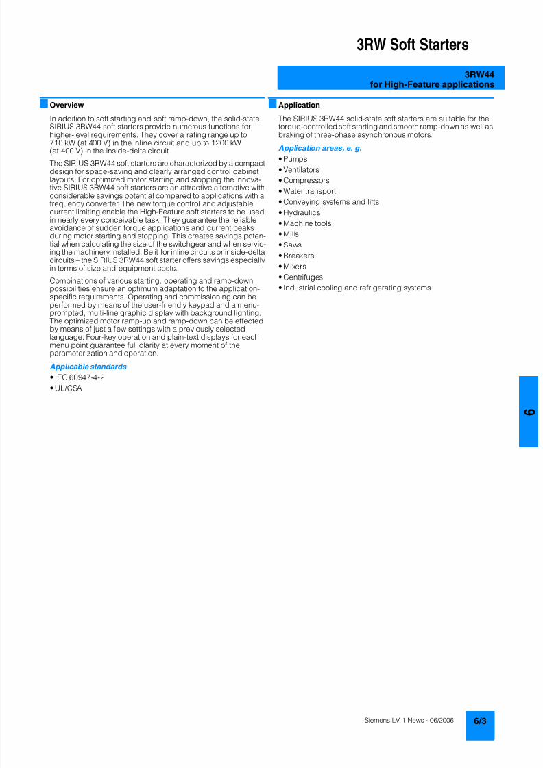
8122019 Arr Estado Solido
httpslidepdfcomreaderfullarr-estado-solido 740
3RW Soft Starters
3RW44for High-Feature applications
Overview
In addition to soft starting and soft ramp-down the solid-stateSIRIUS 3RW44 soft starters provide numerous functions for
higher-level requirements They cover a rating range up to710 kW (at 400 V) in the inline circuit and up to 1200 kW(at 400 V) in the inside-delta circuit
The SIRIUS 3RW44 soft starters are characterized by a compactdesign for space-saving and clearly arranged control cabinetlayouts For optimized motor starting and stopping the innova-tive SIRIUS 3RW44 soft starters are an attractive alternative withconsiderable savings potential compared to applications with afrequency converter The new torque control and adjustablecurrent limiting enable the High-Feature soft starters to be usedin nearly every conceivable task They guarantee the reliableavoidance of sudden torque applications and current peaksduring motor starting and stopping This creates savings poten-tial when calculating the size of the switchgear and when servic-ing the machinery installed Be it for inline circuits or inside-deltacircuits ndash the SIRIUS 3RW44 soft starter offers savings especiallyin terms of size and equipment costs
Combinations of various starting operating and ramp-downpossibilities ensure an optimum adaptation to the application-specific requirements Operating and commissioning can beperformed by means of the user-friendly keypad and a menu-prompted multi-line graphic display with background lightingThe optimized motor ramp-up and ramp-down can be effectedby means of just a few settings with a previously selectedlanguage Four-key operation and plain-text displays for eachmenu point guarantee full clarity at every moment of theparameterization and operation
Applicable standards
bull IEC 60947-4-2
bull ULCSA
Application
The SIRIUS 3RW44 solid-state soft starters are suitable for thetorque-controlled soft starting and smooth ramp-down as well as
braking of three-phase asynchronous motors
Application areas e g
bull Pumps
bull Ventilators
bull Compressors
bull Water transport
bull Conveying systems and lifts
bull Hydraulics
bull Machine tools
bull Mills
bull Saws
bull Breakers
bull Mixersbull Centrifuges
bull Industrial cooling and refrigerating systems
8122019 Arr Estado Solido
httpslidepdfcomreaderfullarr-estado-solido 840
3RW Soft Starters
3RW44for High-Feature applications
Selection and ordering data
1) 3RW44 2 3RW44 3 and 3RW44 4 soft starters with screw-typeterminals delivery time class (preferred type)
2) Control by way of the internal 24 V DC supply and direct control by meansof PLC possible
NoteSoft starter selection depends on the motors rated current
The 3RW44 solid-state soft starters are designed for normalstarting (class 10) (Inertia load of the overall operating mecha- nism JLoad lt 10 x JMotor starting current 350 x Ie for 20 s orsimilar load) For any other conditions of use the devices shouldbe selected using the Win-Soft Starter selection and simulationprogram See Technical Specifications for information aboutrated currents for ambient temperatures gt 40 degC and operatingfrequency
3RW44 27-1BC44 3RW44 36-6BC44 3RW44 47-6BC44 3RW44 58-6BC44
Ambient temperature 40 degC Ambient temperature 50 degC DT Order No Priceper PU
PU(UNITSET M)
PS PG Weightper PUapprox
Ratedopera-tionalcurrent I e
Rated output of three-phase inductionmotors for rated operational voltageU e
Ratedopera-tionalcurrent I e
Rated output of three-phaseinduction motors for ratedoperational voltage U e
230 V 400 V 500 V 690 V 1000 V 200 V 230 V 460 V 575 V
A kW kW kW kW kW A hp hp hp hp kg
Inline circuit rated operational voltage 200 460 V1)
29 55 15 -- -- -- 26 75 75 15 -- 3RW44 22-BC4 1 1 unit 131 490036 75 185 -- -- -- 32 10 10 20 -- 3RW44 23-BC4 1 1 unit 131 490047 11 22 -- -- -- 42 10 15 25 -- 3RW44 24-BC4 1 1 unit 131 4900
57 15 30 -- -- -- 51 15 15 30 -- 3RW44 25-BC4 1 1 unit 131 490077 185 37 -- -- -- 68 20 20 50 -- 3RW44 26-BC4 1 1 unit 131 490093 22 45 -- -- -- 82 25 25 60 -- 3RW44 27-BC4 1 1 unit 131 4900
Order No supplement for connection methods
bull With spring-loaded terminals 3bull With screw terminals 1
113 30 55 -- -- -- 100 30 30 75 -- B 3RW44 34-BC4 1 1 unit 131 7900134 37 75 -- -- -- 117 30 40 75 -- B 3RW44 35-BC4 1 1 unit 131 7900162 45 90 -- -- -- 145 40 50 100 -- B 3RW44 36-BC4 1 1 unit 131 7900
203 55 110 -- -- -- 180 50 60 125 -- B 3RW44 43-BC4 1 1 unit 131 10300250 75 132 -- -- -- 215 60 75 150 -- B 3RW44 44-BC4 1 1 unit 131 10300313 90 160 -- -- -- 280 75 100 200 -- B 3RW44 45-BC4 1 1 unit 131 10300
356 110 200 -- -- -- 315 100 125 250 -- B 3RW44 46-BC4 1 1 unit 131 10300432 132 250 -- -- -- 385 125 150 300 -- B 3RW44 47-BC4 1 1 unit 131 10300
551 160 315 -- -- -- 494 150 200 400 -- C 3RW44 53-BC4 1 1 unit 131 50000615 200 355 -- -- -- 551 150 200 450 -- C 3RW44 54-BC4 1 1 unit 131 50000693 200 400 -- -- -- 615 200 250 500 -- C 3RW44 55-BC4 1 1 unit 131 50000
780 250 450 -- -- -- 693 200 250 600 -- C 3RW44 56-BC4 1 1 unit 131 50000880 250 500 -- -- -- 780 250 300 700 -- C 3RW44 57-BC4 1 1 unit 131 50000970 315 560 -- -- -- 850 300 350 750 -- C 3RW44 58-BC4 1 1 unit 131 50000
Order No supplement for connection methods
bull With spring-loaded terminals 2bull With screw terminals 6
Order No supplement for the rated control supply voltage U s2)
bull 115 V AC 3bull 230 V AC 4
8122019 Arr Estado Solido
httpslidepdfcomreaderfullarr-estado-solido 940
3RW Soft Starters
3RW44for High-Feature applications
1) 3RW44 2 3RW44 3 and 3RW44 4 soft starters with screw-typeterminals delivery time class A
2) Control by way of the internal 24 V DC supply and direct control by meansof PLC possible
NoteSoft starter selection depends on the motors rated current
The 3RW44 solid-state soft starters are designed for normalstarting (class 10) (Inertia load of the overall operating mecha-nism J Load lt 10 x J Motor starting current 350 x I e for 20 s orsimilar load) For any other conditions of use the devices shouldbe selected using the Win-Soft Starter selection and simulationprogram See Technical Specifications for information aboutrated currents for ambient temperatures gt 40 degC and operating
frequency
Ambient temperature 40 degC Ambient temperature 50 degC DT Order No Priceper PU
PU(UNITSET M)
PS PG Weightper PUapprox
Ratedopera-
tionalcurrent I e
Rated output of three-phaseinduction motors for rated operational
voltage U e
Ratedopera-
tionalcurrent I e
Rated output of three-phaseinduction motors for rated
operational voltage U e
230 V 400 V 500 V 690 V 1000 V 200 V 230 V 460 V 575 V
A kW kW kW kW kW A hp hp hp hp kg
Inline circuit rated operational voltage 400 600 V1)
29 -- 15 185 -- -- 26 -- -- 15 20 A 3RW44 22-BC5 1 1 unit 131 490036 -- 185 22 -- -- 32 -- -- 20 25 A 3RW44 23-BC5 1 1 unit 131 490047 -- 22 30 -- -- 42 -- -- 25 30 A 3RW44 24-BC5 1 1 unit 131 4900
57 -- 30 37 -- -- 51 -- -- 30 40 A 3RW44 25-BC5 1 1 unit 131 490077 -- 37 45 -- -- 68 -- -- 50 50 A 3RW44 26-BC5 1 1 unit 131 490093 -- 45 55 -- -- 82 -- -- 60 75 A 3RW44 27-BC5 1 1 unit 131 4900
Order No supplement for connection methods
bull With spring-loaded terminals 3bull With screw terminals 1
113 -- 55 75 -- -- 100 -- -- 75 75 B 3RW44 34-BC5 1 1 unit 131 7900134 -- 75 90 -- -- 117 -- -- 75 100 B 3RW44 35-BC5 1 1 unit 131 7900
162 -- 90 110 -- -- 145 -- -- 100 125 B 3RW44 36-BC5 1 1 unit 131 7900
203 -- 110 132 -- -- 180 -- -- 125 150 B 3RW44 43-BC5 1 1 unit 131 10300250 -- 132 160 -- -- 215 -- -- 150 200 B 3RW44 44-BC5 1 1 unit 131 10300313 -- 160 200 -- -- 280 -- -- 200 250 B 3RW44 45-BC5 1 1 unit 131 10300
356 -- 200 250 -- -- 315 -- -- 250 300 B 3RW44 46-BC5 1 1 unit 131 10300432 -- 250 315 -- -- 385 -- -- 300 400 B 3RW44 47-BC5 1 1 unit 131 10300
551 -- 315 355 -- -- 494 -- -- 400 500 C 3RW44 53-BC5 1 1 unit 131 50000615 -- 355 400 -- -- 551 -- -- 450 600 C 3RW44 54-BC5 1 1 unit 131 50000693 -- 400 500 -- -- 615 -- -- 500 700 C 3RW44 55-BC5 1 1 unit 131 50000
780 -- 450 560 -- -- 693 -- -- 600 750 C 3RW44 56-BC5 1 1 unit 131 50000880 -- 500 630 -- -- 780 -- -- 700 850 C 3RW44 57-BC5 1 1 unit 131 50000970 -- 560 710 -- -- 850 -- -- 750 950 C 3RW44 58-BC5 1 1 unit 131 50000
Order No supplement for connection methods
bull With spring-loaded terminals 2bull With screw terminals 6
Order No supplement for the rated control supply voltage U s2)
bull 115 V AC 3bull 230 V AC 4
You can order this quantity or a multiple thereof
8122019 Arr Estado Solido
httpslidepdfcomreaderfullarr-estado-solido 1040
3RW Soft Starters
3RW44for High-Feature applications
1) Control by way of the internal 24 V DC supply and direct control by meansof PLC possible
NoteSoft starter selection depends on the motors rated current
The 3RW44 solid-state soft starters are designed for normalstarting (class 10) (Inertia load of the overall operating mecha- nism J Load lt 10 x J Motor starting current 350 x I e for 20 s orsimilar load) For any other conditions of use the devices shouldbe selected using the Win-Soft Starter selection and simulationprogram See Technical Specifications for information aboutrated currents for ambient temperatures gt 40 degC and operatingfrequency
Ambient temperature 40 degC Ambient temperature 50 degC DT Order No Priceper PU
PU(UNITSET M)
PS PG Weightper PUapprox
Ratedopera-
tionalcurrent I e
Rated output of three-phaseinduction motors for rated operational
voltage U e
Ratedopera-
tionalcurrent I e
Rated output of three-phaseinduction motors for rated
operational voltage U e
230 V 400 V 500 V 690 V 1000 V 200 V 230 V 460 V 575 V
A kW kW kW kW kW A hp hp hp hp kg
Inline circuit rated operational voltage 400 690 V
29 -- 15 185 30 -- 26 -- -- 15 20 B 3RW44 22-BC6 1 1 unit 131 490036 -- 185 22 37 -- 32 -- -- 20 25 B 3RW44 23-BC6 1 1 unit 131 490047 -- 22 30 45 -- 42 -- -- 25 30 B 3RW44 24-BC6 1 1 unit 131 4900
57 -- 30 37 55 -- 51 -- -- 30 40 B 3RW44 25-BC6 1 1 unit 131 490077 -- 37 45 75 -- 68 -- -- 50 50 B 3RW44 26-BC6 1 1 unit 131 490093 -- 45 55 90 -- 82 -- -- 60 75 B 3RW44 27-BC6 1 1 unit 131 4900
Order No supplement for connection methods
bull With spring-loaded terminals 3bull With screw terminals 1
113 -- 55 75 110 -- 100 -- -- 75 75 B 3RW44 34-BC6 1 1 unit 131 7900134 -- 75 90 132 -- 117 -- -- 75 100 B 3RW44 35-BC6 1 1 unit 131 7900
162 -- 90 110 160 -- 145 -- -- 100 125 B 3RW44 36-BC6 1 1 unit 131 7900
203 -- 110 132 200 -- 180 -- -- 125 150 B 3RW44 43-BC6 1 1 unit 131 10300250 -- 132 160 250 -- 215 -- -- 150 200 B 3RW44 44-BC6 1 1 unit 131 10300313 -- 160 200 315 -- 280 -- -- 200 250 B 3RW44 45-BC6 1 1 unit 131 10300
356 -- 200 250 355 -- 315 -- -- 250 300 B 3RW44 46-BC6 1 1 unit 131 10300432 -- 250 315 400 -- 385 -- -- 300 400 B 3RW44 47-BC6 1 1 unit 131 10300
551 -- 315 355 560 -- 494 -- -- 400 500 C 3RW44 53-BC6 1 1 unit 131 50000615 -- 355 400 630 -- 551 -- -- 450 600 C 3RW44 54-BC6 1 1 unit 131 50000693 -- 400 500 710 -- 615 -- -- 500 700 C 3RW44 55-BC6 1 1 unit 131 50000
780 -- 450 560 800 -- 693 -- -- 600 750 C 3RW44 56-BC6 1 1 unit 131 50000880 -- 500 630 900 -- 780 -- -- 700 850 C 3RW44 57-BC6 1 1 unit 131 50000970 -- 560 710 1000 -- 850 -- -- 750 950 C 3RW44 58-BC6 1 1 unit 131 50000
Order No supplement for connection methods
bull With spring-loaded terminals 2bull With screw terminals 6
Order No supplement for the rated control supply voltage U s1)
bull 115 V AC 3bull 230 V AC 4
8122019 Arr Estado Solido
httpslidepdfcomreaderfullarr-estado-solido 1140
3RW Soft Starters
3RW44for High-Feature applications
1) In the selection table the unit rated operational current I e refers to the
three-phase motors rated operational current in the inside-delta circuitThe actual current of the unit is approx 58 of this value
2) 3RW44 2 3RW44 3 and 3RW44 4 soft starters with screw-typeterminals delivery time class (preferred type)
3) Control by way of the internal 24 V DC supply and direct control by meansof PLC possible
NoteSoft starter selection depends on the motors rated current
The 3RW44 solid-state soft starters are designed for normalstarting (class 10) (Inertia load of the overall operatingmechanism JLoad lt 10 x JMotor starting current 350 x Ie for20 s or similar load) For any other conditions of use the devicesshould be selected using the Win-Soft Starter selection andsimulation program See Technical Specifications for informationabout rated currents for ambient temperatures gt 40 degC andoperating frequency
3RW44 27-1BC44 3RW44 36-6BC44 3RW44 47-6BC44 3RW44 58-6BC44
Ambient temperature 40 degC Ambient temperature 50 degC DT Order No Priceper PU
PU(UNITSET M)
PS PG Weightper PUapprox
Ratedopera-tionalcurrent I e
1)
Rated output of three-phase inductionmotors for rated operational voltageU e
Ratedopera-tionalcurrent I e
Rated output of three-phaseinduction motors for ratedoperational voltage U e
230 V 400 V 500 V 690 V 1000 V 200 V 230 V 460 V 575 V
A kW kW kW kW kW A hp hp hp hp kgInside-delta circuits rated operational voltage 200 460 V2)
50 15 22 -- -- -- 45 10 15 30 -- B 3RW44 22-BC4 1 1 unit 131 490062 185 30 -- -- -- 55 15 20 40 -- B 3RW44 23-BC4 1 1 unit 131 490081 22 45 -- -- -- 73 20 25 50 -- B 3RW44 24-BC4 1 1 unit 131 4900
99 30 55 -- -- -- 88 25 30 60 -- B 3RW44 25-BC4 1 1 unit 131 4900133 37 75 -- -- -- 118 30 40 75 -- B 3RW44 26-BC4 1 1 unit 131 4900161 45 90 -- -- -- 142 40 50 100 -- B 3RW44 27-BC4 1 1 unit 131 4900
Order No supplement for connection methods
bull With spring-loaded terminals 3bull With screw terminals 1
196 55 110 -- -- -- 173 50 60 125 -- B 3RW44 34-BC4 1 1 unit 131 7900232 75 132 -- -- -- 203 60 75 150 -- B 3RW44 35-BC4 1 1 unit 131 7900281 90 160 -- -- -- 251 75 100 200 -- B 3RW44 36-BC4 1 1 unit 131 7900
352 110 200 -- -- -- 312 100 125 250 -- B 3RW44 43-BC4 1 1 unit 131 10300433 132 250 -- -- -- 372 125 150 300 -- B 3RW44 44-BC4 1 1 unit 131 10300542 160 315 -- -- -- 485 150 200 400 -- B 3RW44 45-BC4 1 1 unit 131 10300
617 200 355 -- -- -- 546 150 200 450 -- B 3RW44 46-BC4 1 1 unit 131 10300748 250 400 -- -- -- 667 200 250 600 -- B 3RW44 47-BC4 1 1 unit 131 10300
954 315 560 -- -- -- 856 300 350 750 -- C 3RW44 53-BC4 1 1 unit 131 500001065 355 630 -- -- -- 954 350 400 850 -- C 3RW44 54-BC4 1 1 unit 131 500001200 400 710 -- -- -- 1065 350 450 950 -- C 3RW44 55-BC4 1 1 unit 131 50000
1351 450 800 -- -- -- 1200 450 500 1050 -- C 3RW44 56-BC4 1 1 unit 131 500001524 500 900 -- -- -- 1351 450 600 1200 -- C 3RW44 57-BC4 1 1 unit 131 500001680 560 1000 -- -- -- 1472 550 650 1300 -- C 3RW44 58-BC4 1 1 unit 131 50000
Order No supplement for connection methods
bull With spring-loaded terminals 2bull With screw terminals 6
Order No supplement for the rated control supply voltage U s3)
bull 115 V AC 3bull 230 V AC 4
You can order this quantity or a multiple thereof
8122019 Arr Estado Solido
httpslidepdfcomreaderfullarr-estado-solido 1240
3RW Soft Starters
3RW44for High-Feature applications
1) In the selection table the unit rated operational current I e refers to thethree-phase motors rated operational current in the inside-delta circuitThe actual current of the unit is approx 58 of this value
2) 3RW44 2 3RW44 3 and 3RW44 4 soft starters with screw-typeterminals delivery time class A
3) Control by way of the internal 24 V DC supply and direct control by meansof PLC possible
Accessories
NoteSoft starter selection depends on the motors rated current
The 3RW44 solid-state soft starters are designed for normalstarting (class 10) (Inertia load of the overall operatingmechanism J Load lt 10 x J Motor starting current 350 x I e for20 s or similar load) For any other conditions of use the devicesshould be selected using the Win-Soft Starter selection andsimulation program See Technical Specifications for informationabout rated currents for ambient temperatures gt 40 degC andoperating frequency
Ambient temperature 40 degC Ambient temperature 50 degC DT Order No Priceper PU
PU(UNITSET M)
PS PG Weightper PUapprox
Ratedopera-
tionalcurrent I e
1)
Rated output of three-phaseinduction motors for rated opera-
tional voltage U e
Ratedopera-
tionalcurrent I e
Rated output of three-phaseinduction motors for rated
operational voltage U e
230 V 400 V 500 V 690 V 1000 V 200 V 230 V 460 V 575 V
A kW kW kW kW kW A hp hp hp hp kg
Inside-delta circuits rated operational voltage 400 600 V2)
50 -- 22 30 -- -- 45 -- -- 30 40 B 3RW44 22-BC5 1 1 unit 131 490062 -- 30 37 -- -- 55 -- -- 40 50 B 3RW44 23-BC5 1 1 unit 131 490081 -- 45 45 -- -- 73 -- -- 50 60 B 3RW44 24-BC5 1 1 unit 131 4900
99 -- 55 55 -- -- 88 -- -- 60 75 B 3RW44 25-BC5 1 1 unit 131 4900133 -- 75 90 -- -- 118 -- -- 75 100 B 3RW44 26-BC5 1 1 unit 131 4900161 -- 90 110 -- -- 142 -- -- 100 125 B 3RW44 27-BC5 1 1 unit 131 4900
Order No supplement for connection methods
bull With spring-loaded terminals 3bull With screw terminals 1
196 -- 110 132 -- -- 173 -- -- 125 150 B 3RW44 34-BC5 1 1 unit 131 7900232 -- 132 160 -- -- 203 -- -- 150 200 B 3RW44 35-BC5 1 1 unit 131 7900
281 -- 160 200 -- -- 251 -- -- 200 250 B 3RW44 36-BC5 1 1 unit 131 7900
352 -- 200 250 -- -- 312 -- -- 250 300 B 3RW44 43-BC5 1 1 unit 131 10300433 -- 250 315 -- -- 372 -- -- 300 350 B 3RW44 44-BC5 1 1 unit 131 10300542 -- 315 355 -- -- 485 -- -- 400 500 B 3RW44 45-BC5 1 1 unit 131 10300
617 -- 355 450 -- -- 546 -- -- 450 600 B 3RW44 46-BC5 1 1 unit 131 10300748 -- 400 500 -- -- 667 -- -- 600 750 B 3RW44 47-BC5 1 1 unit 131 10300
954 -- 560 630 -- -- 856 -- -- 750 950 C 3RW44 53-BC5 1 1 unit 131 500001065 -- 630 710 -- -- 954 -- -- 850 1050 C 3RW44 54-BC5 1 1 unit 131 500001200 -- 710 800 -- -- 1065 -- -- 950 1200 C 3RW44 55-BC5 1 1 unit 131 50000
1351 -- 800 900 -- -- 1200 -- -- 1050 1350 C 3RW44 56-BC5 1 1 unit 131 500001524 -- 900 1000 -- -- 1351 -- -- 1200 1500 C 3RW44 57-BC5 1 1 unit 131 500001680 -- 1000 1200 -- -- 1472 -- -- 1300 1650 C 3RW44 58-BC5 1 1 unit 131 50000
Order No supplement for connection methods
bull With spring-loaded terminals 2bull With screw terminals 6
Order No supplement for the rated control supply voltage U s3)
bull 115 V AC 3bull 230 V AC 4
Forsoft starters Version DT Order No Priceper PU PU(UNITSET M)
PS PG Weightper PUapprox
Type kg
Soft Starter ES 2006 PC communication program
Soft Starter ES 2006 Smart
Parameterization and service software forSIRIUS 3RW44 soft starters for parameterizingthrough the system interface on the deviceExecutes on PCPG under Windows 2000XPwithout PC cableType of supply CD single license
3ZS1 313-1CC10-0YA0 1 1 unit 131 0230
3ZS1 313-1CC10-0YA0 Soft Starter ES 2006 Professional
Parameterization and service software forSIRIUS 3RW44 soft starters for parameterizingthrough the system interface on the device andPROFIBUS DP interface (PROFIBUS as optional commu-nication module necessary)Executes on PCPG under Windows 2000XPwithout PC cableType of supply CD single license
A 3ZS1 313-2CC10-0YA0 1 1 unit 131 0230
8122019 Arr Estado Solido
httpslidepdfcomreaderfullarr-estado-solido 1340
3RW Soft Starters
3RW44for High-Feature applications
Spare parts
Forsoft starters
Version DT Order No Priceper PU
PU(UNITSET M)
PS PG Weightper PUapprox
Type kg
PC cables
For PCPG communication with SIRIUS 3RW44soft starters
through the system interface for connecting tothe serial interface of the PCPG
B 3UF7 940-0AA00-0 1 1 unit 131 0150
Box terminal blocks for soft starters
Box terminal blocks
3RW44 2 Included in del ivery
3RW44 3 bull Up to 70 mm2 3RT19 55-4G 1 1 unit 101 0237
bull Up to 120 mm2 3RT19 56-4G 1 1 unit 101 0270
3RW44 3 bull Up to 240 mm2 3RT19 66-4G 1 1 unit 101 0676
PROFIBUS Communication moduleModule to be plugged into the soft starter to connect thesoft starter to the PROFIBUS net
A 3RW4 900-0KC00 1 1 unit 131 0320
External display and operation module
to show and operate the fonctions supplied by the softstarter via externally mounted display and operationmodule(for example in the cubicle door)
A 3RW4 900-0AC00 1 1 unit 131 0320
Connection cable
from serial interface of 3RW44 soft starter to external dis-play and operation modulebull Length 05 m flat B 3UF7 932-0AA00-0 1 1 unit 131 0020bull Length 05 m round A 3UF7 932-0BA00-0 1 1 unit 131 0050bull Length10 m round A 3UF7 937-0BA00-0 1 1 unit 131 0100bull Length25 m round A 3UF7 933-0BA00-0 1 1 unit 131 0150
Covers for soft starters
Terminal covers for box terminals
Additional touch protection to be fitted at the boxterminals (2 units required per device)
3RW44 2 and3RW44 3
3RT19 56-4EA2 1 1 unit 101 0028
3RW44 4 3RT19 66-4EA2 1 1 unit 101 0038
Terminal covers for cable lugs and busbarconnections
3RW44 2 and3RW44 3
3RT19 56-4EA1 1 1 unit 101 0067
3RW44 4 3RT19 66-4EA1 1 1 unit 101 0124
Forsoft starters
Version DT Order No Priceper PU
PU(UNITSET M)
PS PG Weightper PUapprox
Type kg
Fans
Fans
3RW44 2 and3RW44 3
115 VAC 3RW49 36-8VX30 1 1 unit 131 0300230 VAC 3RW49 36-8VX40 1 1 unit 131 0300
3RW44 4 115 V AC 3RW49 47-8VX30 1 1 unit 131 0500230 VAC 3RW49 47-8VX40 1 1 unit 131 0500
3RW44 5 115 V AC 3RW49 57-8VX30 1 1 unit 131 0800230 VAC 3RW49 57-8VX40 1 1 unit 131 0800
You can order this quantity or a multiple thereof
8122019 Arr Estado Solido
httpslidepdfcomreaderfullarr-estado-solido 1440
3RW Soft Starters
3RW44for High-Feature applications
Function
Equipped with modern ergonomic user prompting theSIRIUS 3RW44 soft starters can be commissioned quickly and
easily using a keypad and a menu-prompted multi-line displaywith background lighting Motor starting and deceleration areoptimized quickly easily and safely with just a few settings in aselectable language Four-key operation and plain-text displaysfor each menu point guarantee full clarity at every moment of theparameterization and operation Measurement values and oper-ating values as well as warning messages and fault indicationsare output continuously on the front panel during operation andwhen control voltage is applied An external display and opera-tor module can be connected by means of a connecting cableto the soft starter thus enabling active indications and the like tobe read directly from the control cabinet door
The SIRIUS 3RW44 soft starters are equipped with optimumfunctionality An integral bypass contact system reduces thepower loss of the soft starter during operation This reliablyprevents heating of the switchgear environment TheSIRIUS 3RW44 soft starters have internal intrinsic deviceprotection This prevents thermal overloading of the powersections thyristors eg due to unacceptably high closingoperations
Wiring work for installing an additional motor overload relay is nolonger needed as the SIRIUS 3RW44 soft starters perform thisfunction too In addition they offer adjustable trip classes and athermistor motor protection function As an option the thyristorscan also be protected by SITOR semi-conductor fuses fromshort-circuiting And even inrush current peaks are reliablyavoided thanks to adjustable current limiting
As a further option the SIRIUS 3RW44 soft starters can beupgraded with a PROFIBUS DP module Thanks to their commu-nication capability and their programmable control inputs andrelay outputs the SIRIUS 3RW44 soft starters can be very easily
and quickly integrated in higher-level controllersIn addition a creep speed function is available for positioningand setting jobs With this function the motor can be controlledin both directions of rotation with reduced torque and an adjust-able low speed
On the other hand the SIRIUS 3RW44 soft starters offer a newcombined DC braking function for the fast stopping of drivingloads
Highlights bull Soft starting with breakaway pulse torque control or voltage
ramp and adjustable torque or current limiting as well as anycombination of these depending on load type
bull Integrated bypass contact system to minimize dissipatedpower
bull Various setting options for the starting parameters such asstarting torque starting voltage ramp-up and ramp-downtime and much more in three separate parameter sets
bull Start-up detectionbull Inside-delta circuit for savings in terms of size and equipment
costsbull Various ramp-down modes selectable free ramp-down
torque-controlled pump stopping combined DC brakingbull Solid-state motor overload and intrinsic device protectionbull Thermistor motor protectionbull Keypad with a menu-controlled multi-line graphic display with
background lighting
bull Interface for communication with the PC for more accuratesetting of the parameters as well as for control and monitoringbull Simple adaptation to the motor feederbull Simple mounting and commissioningbull Display of operating states and fault signalsbull Connection to PROFIBUS with optional PROFIBUS DP modulebull External display and operator modulebull System voltages from 200 to 690 V 50 to 60 Hzbull Applicable up to 60 degC (derating from 40 degC)
8122019 Arr Estado Solido
httpslidepdfcomreaderfullarr-estado-solido 1540
3RW Soft Starters
3RW44for High-Feature applications
Technical specifications
Type 3RW44 -BC3 3RW44 -BC4Terminal
Control electronics
Rated valuesRated control supply voltage A1A2PE V 115 AC 230 ACbull Tolerance -15+10 -15+10Rated control supply current STANDBY mA 30 20
Rated control supply current ONbull 3RW44 2 mA 300 170bull 3RW44 3 mA 500 250bull 3RW44 4 mA 750 400bull 3RW44 5 mA 450 200
Maximum current (pickup bypass)bull 3RW44 2 mA 1000 500bull 3RW44 3 mA 2500 1250bull 3RW44 4 mA 6000 3000bull 3RW44 5 mA 4500 2500
Rated frequency Hz 50 60 50 60bull Tolerance plusmn10 plusmn10
Type 3RW44 Terminal Factory presetting
Control electronics
Control inputsInput 1 IN1 Start motor right parameter set 1Input 2 IN2 No actionInput 3 IN3 No actionInput 4 IN4 Trip reset
Supply L+L-bull Rated operational current mA Approx 10 per input to DIN 19240bull Rated operational voltage L+ Internal voltage 24 V DC from inter-
nal supply through terminal L+ toIN1 IN4 Maximum load at L+approx 55 mA
L- External voltage DC external voltage(to DIN19240) through terminals
L- and IN1 IN4(min 12 V DC max 30 V DC)
Thermistor motor protection inputInput T1T2 PTC type A or Thermoclick Deactivated
Relay outputs (floating auxiliary contacts)Output 1 1314 ON periodOutput 2 2324 No actionOutput 3 3334 No actionOutput 4 959698 Group fault
Switching capacity of the relay outputs230 VAC-15 A 3 at 240 V24 VDC-13 A 1 at 24 VProtection against overvoltages Protection by means of Varistor through relay contactShort-circuit protection 4 A gLgG operational class
6 A quick (fuse is not included in scope of supply)
Protective functions
Motor protection functionsTrips in the event of Thermal overloading of the motor
Trip class to IEC 60947-4-1 Class 510152030 10Phase failure sensitivity gt 40
Overload warning yesReset and recovery ManualAutomatic ManualReset option after tripping ManualAutomatic ManualRecovery time min 1 30 1
Device protection functionsTrips in the event of Thermal overloading of the thyristorsReset option after tripping ManualAutomatic ManualRecovery time min 05
8122019 Arr Estado Solido
httpslidepdfcomreaderfullarr-estado-solido 1640
3RW Soft Starters
3RW44for High-Feature applications
Type 3RW44 Factory presetting
Control times and parameters
Control timesClosing delay (with connected control voltage) ms lt 50Closing delay (automatic mode) ms lt 4000Recovery time (closing command in active ramp-down) ms lt 100
Mains failure bridging timeControl supply voltage ms 100
Mains failure response timeLoad current circuit ms 100
Reclosing lockout after overload tripMotor protection trip min 1 30 1Device protection trip s 30
Setting options for startingVoltage ramp for starting voltage 20 100 30Torque control for starting torque 20 100 50Torque control for limit torque 20 200 150
Starting time s 0 360 20Maximum starting time s 1 1000 DeactivatedCurrent limit value 125 550 450
Breakaway voltage 40 100 80Breakaway time s 0 2 DeactivatedMotor heat output 0 100 0
Creep mode LeftRight runningSpeed factor as function of rated speed (n = n rated factor) 3 21 7Creep torque (reference variable depends on the motor used but isalways smaller than the rated torque of the motor)
20 100 50
Setting options for ramp-downTorque control for stopping torque 10 100 10Ramp-down time s 0 360 10Dynamic braking torque 20 100 50DC braking torque 20 100 50
Operating indicationsTest voltageTest mains phasesReady to start
Start active
Motor runningRamp-down active
Warningserror signalsMains voltage missingLeading-edge phase error
Phase failurebull L1bull L2bull L3
Missing load phasebull T1bull T2bull T3
Failurebull Contact element 1 (thyristor)bull Contact element 2 (thyristor)bull Contact element 3 (thyristor)
Flash memory faulty
Supply voltagebull Below 75 bull Below 85 bull Over 110
Current unbalance exceededThermal motor model overload
Prewarning limit exceededbull Motor heatingbull Time-related trip reserve
Bypass elements defectiveMains voltage too high
Device not namedWrong naming versionCurrent range exceeded
Motor blocking ndash shutdownCurrent limit exceeded
Power section
bull Overheatedbull OvertemperatureEmergency active
8122019 Arr Estado Solido
httpslidepdfcomreaderfullarr-estado-solido 1740
3RW Soft Starters
3RW44for High-Feature applications
1) Parameter motor left possible only in conjunction with creep mode
Type 3RW44 Factory presetting
Control times and parameters
Warningserror signals (contd)Temperature sensorbull Overloadbull Open-circuitbull Short-circuit
Ground faultbull Detectedbull Shutdown
Connection abort in manual modeMax number of starts exceeded I e limit value overshootundershoot
Cooling timebull Motor activebull Switch block active
Heat sink sensorbull Open-circuitbull Short-circuit
Quick-stop functionSwitch block faulty I e class setting not permissible
Control inputsInput 1 Motor right parameter set 1Input 2 No actionInput 3 No actionInput 4 Trip reset
Parameterizing options for control inputs 1 4 No actionLocal manual modeEmergency startCreep speedQuick-stopTrip reset
Motor right parameter set 1Motor left parameter set 11) Motor right parameter set 2Motor left parameter set 21) Motor right parameter set 3Motor left parameter set 31)
Relay outputsOutput 1 ON periodOutput 2 No actionOutput 3 No actionOutput 4 Group fault
Parameterizing options for relay outputs 1 3 No actionPAA output 1PAA output 2
Input 1Input 2Input 3Input 4
Ramp-upOperationBypassRamp-downON periodCommand motor on
FanDC braking contactor
Group warningGroup faultBus faultDevice error
Power onReady to start
Motor temperature sensors Deactivated DeactivatedThermoclickPTC type A
8122019 Arr Estado Solido
httpslidepdfcomreaderfullarr-estado-solido 1840
3RW Soft Starters
3RW44for High-Feature applications
1) Current limit on soft starter set to 350 I M
2) For intermittent duty S4 with ON period = 70 T u = 40 degC stand-aloneinstallation vertical The quoted operating frequencies do not apply forautomatic mode
3) Maximum adjustable rated motor current I M dependent on CLASS setting
Type 3RW44 -BC4 3RW44 -BC5 3RW44 -BC6
Power electronics
Rated operational voltage for inline circuit V 200 460 AC 400 600 AC 400 690 AC
Tolerance -15+10 -15+10 -15+10Rated operational voltage for inside-delta circuit V 200 460 AC 400 600 AC 400 600 ACTolerance -15+10 -15+10 -15+10
Rated frequency Hz 50 60Tolerance plusmn10
Continuous operation at 40 degC ( of I e) 115
Minimum load ( of set motor current I M) 8
Maximum conductor length between soft starter and motor m 200
Permissible installation height m 5000 (derating from 1000 see characteristics) higher on request
Permissible mounting position
Permissible ambient temperatureOperation degC 0 +60 (derating from +40)Storage degC -25 +80
Degree of protection IP00
Type 3RW44 22 3RW44 23 3RW44 24 3RW44 25 3RW44 26 3RW44 27
Power electronics
Rated operational current I e 29 36 47 57 77 93
Load rating with rated operational current I ebull Acc to IEC and ULCSA for individual mounting
at 405060 degC AC-53a A 292623 363229 474237 575145 776859 938272
Smallest adjustable rated motor current I Mfor the motor overload protection
A 5 7 9 11 15 18
Power lossbull In operation after completed ramp-up with uninterrupted rated
operational current (40 degC) approx W 8 10 32 36 45 55bull During starting with current limit set to 350 I M (40 degC) W 400 470 600 725 940 1160
Permissible rated motor current and starts per hour
bull Normal starting (Class 5)- Rated motor current I M
1) starting time 5 s A 29 36 47 57 77 93- Starts per hour2) 1h 41 34 41 41 41 41
- Rated motor current I M1)3) starting time 10 s A 29 36 47 57 77 93
- Starts per hour2) 1h 20 15 20 20 20 20
bull Normal starting (Class 10)- Rated motor current I M
1) starting time 10 s A 29 36 47 57 77 93- Starts per hour2) 1h 20 15 20 20 20 20
- Rated motor current I M1)3) starting time 20 s A 29 36 47 57 77 93
- Starts per hour2) 1h 10 6 10 10 8 8
bull Normal starting (Class 15)- Rated motor current I M
1) starting time 15 s A 29 36 47 57 77 93- Starts per hour2) 1h 13 9 13 13 13 13
- Rated motor current I M1)3) starting time 30 s A 29 36 47 57 77 93
- Starts per hour2) 1h 6 4 6 6 6 6
bull For heavy starting (Class 20)- Rated motor current I M
1) starting time 20 s A 29 36 47 57 73 88- Starts per hour2) 1h 10 6 10 10 10 10
- Rated motor current I M1)3) starting time 40 s A 29 36 47 57 73 88
- Starts per hour2) 1h 4 2 4 5 18 08
bull For very heavy starting (Class 30)- Rated motor current I M
1) starting time 30 s A 29 36 44 57 65 77- Starts per hour2) 1h 6 4 6 6 6 6
- Rated motor current I M1)3) starting time 60 s A 29 36 44 57 65 77
- Starts per hour2) 1h 18 08 33 15 2 1
8122019 Arr Estado Solido
httpslidepdfcomreaderfullarr-estado-solido 1940
3RW Soft Starters
3RW44for High-Feature applications
1) Current limit on soft starter set to 350 I M
2) For intermittent duty S4 with ON period = 70 T u = 40 degC stand-aloneinstallation vertical The quoted operating frequencies do not apply forautomatic mode
3) Maximum adjustable rated motor current I M dependent on CLASS setting
Type 3RW44 34 3RW44 35 3RW44 36
Power electronics
Rated operational current I e 113 134 162
Load rating with rated operational current I ebull Acc to IEC and ULCSA for individual mounting AC-53a
- at 40 degC A 113 134 162- at 50 degC A 100 117 145- at 60 degC A 88 100 125
Smallest adjustable rated motor current I Mfor the motor overload protection
A 22 26 32
Power lossbull In operation after completed ramp-up with uninterrupted rated
operational current (40 degC) approx W 64 76 95bull During starting with current limit set to 350 I M (40 degC) W 1350 1700 2460
Permissible rated motor current and starts per hour
bull Normal starting (Class 5)- Rated motor current I M
1) starting time 5 s A 113 134 162- Starts per hour2) 1h 41 39 41
- Rated motor current I M1)3) starting time 10 s A 113 134 162
- Starts per hour2) 1h 20 15 20
bull Normal starting (Class 10)- Rated motor current I M
1) starting time 10 s A 113 134 162- Starts per hour2) 1h 20 15 20
- Rated motor current I M1)3) starting time 20 s A 113 134 162
- Starts per hour2) 1h 9 6 7
bull Normal starting (Class 15)- Rated motor current I M
1) starting time 15 s A 113 134 162- Starts per hour2) 1h 13 9 12
- Rated motor current I M1)3) starting time 30 s A 113 134 162
- Starts per hour2) 1h 6 6 1
bull For heavy starting (Class 20)- Rated motor current I M
1) starting time 20 s A 106 125 147- Starts per hour2) 1h 9 9 10
- Rated motor current I M1)3) starting time 40 s A 106 125 147
- Starts per hour2) 1h 15 2 1
bull For very heavy starting (Class 30)- Rated motor current I M
1) starting time 30 s A 91 110 120
- Starts per hour2) 1h 6 6 6- Rated motor current I M
1)3) starting time 60 s A 91 110 120- Starts per hour2) 1h 2 2 2
8122019 Arr Estado Solido
httpslidepdfcomreaderfullarr-estado-solido 2040
3RW Soft Starters
3RW44for High-Feature applications
1) Current limit on soft starter set to 350 I M
2) For intermittent duty S4 with ON period = 70 T u = 40 degC stand-aloneinstallation vertical The quoted operating frequencies do not apply forautomatic mode
3) Maximum adjustable rated motor current I M dependent on CLASS setting
Type 3RW44 43 3RW44 44 3RW44 45 3RW44 46 3RW44 47
Power electronics
Rated operational current I e 203 250 313 356 432
Load rating with rated operational current I ebull Acc to IEC and ULCSA for individual mounting AC-53a
- at 40 degC A 203 250 313 356 432- at 50 degC A 180 215 280 315 385- at 60 degC A 156 185 250 280 335
Smallest adjustable rated motor current I Mfor the motor overload protection
A 40 50 62 71 86
Power lossbull In operation after completed ramp-up with uninterrupted rated
operational current (40 degC) approx W 89 110 145 174 232bull During starting with current limit set to 350 I M (40 degC) W 3350 4000 4470 5350 5860
Permissible rated motor current and starts per hour
bull Normal starting (Class 5)- Rated motor current I M
1) starting time 5 s A 203 250 313 356 432- Starts per hour2) 1h 41 41 41 41 39
- Rated motor current I M1)3) starting time 10 s A 203 250 313 356 432
- Starts per hour2) 1h 20 20 19 17 16
bull Normal starting (Class 10)- Rated motor current I M
1) starting time 10 s A 203 250 313 356 432- Starts per hour2) 1h 20 20 19 17 16
- Rated motor current I M1)3) starting time 20 s A 203 250 313 356 432
- Starts per hour2) 1h 9 10 6 4 5
bull Normal starting (Class 15)- Rated motor current I M
1) starting time 15 s A 203 240 313 325 402- Starts per hour2) 1h 13 13 10 13 11
- Rated motor current I M1)3) starting time 30 s A 203 240 313 325 402
- Starts per hour2) 1h 3 6 1 2 1
bull For heavy starting (Class 20)- Rated motor current I M
1) starting time 20 s A 195 215 275 285 356- Starts per hour2) 1h 10 10 10 10 10
- Rated motor current I M1)3) starting time 40 s A 195 215 275 285 356
- Starts per hour2) 1h 1 5 1 3 1
bull For very heavy starting (Class 30)- Rated motor current I M
1) starting time 30 s A 162 180 220 240 285
- Starts per hour2) 1h 6 6 6 6 6- Rated motor current I M
1)3) starting time 60 s A 162 180 220 240 285- Starts per hour2) 1h 3 3 3 2 1
8122019 Arr Estado Solido
httpslidepdfcomreaderfullarr-estado-solido 2140
3RW Soft Starters
3RW44for High-Feature applications
1) Current limit on soft starter set to 350 I M
2) For intermittent duty S4 with ON period = 70 T u = 40 degC stand-aloneinstallation vertical The quoted operating frequencies do not apply forautomatic mode
3) Maximum adjustable rated motor current I M dependent on CLASS setting
Type 3RW44 53 3RW44 54 3RW44 55 3RW44 56 3RW44 57 3RW44 58
Power electronics
Rated operational current I e 551 615 693 780 880 970
Load rating with rated operational current I ebull Acc to IEC and ULCSA for individual mounting AC-53a
- at 40 degC A 551 615 693 780 880 970- at 50 degC A 494 551 615 693 780 850- at 60 degC A 438 489 551 615 693 760
Smallest adjustable rated motor current I Mfor the motor overload protection
A 110 123 138 156 176 194
Power lossbull In operation after completed ramp-up with uninterrupted rated
operational current (40 degC) approx W 159 186 220 214 250 270bull During starting with current limit set to 350 I M (40 degC) W 7020 8100 9500 11100 13100 15000
Permissible rated motor current and starts per hour
bull Normal starting (Class 5)- Rated motor current I M
1) starting time 5 s A 551 615 693 780 880 970- Starts per hour2) 1h 41 41 37 33 22 17
- Rated motor current I M1)3) starting time 10 s A 551 615 693 780 880 970
- Starts per hour2) 1h 20 20 16 13 8 5
bull Normal starting (Class 10)- Rated motor current I M
1) starting time 10 s A 551 615 693 780 880 970- Starts per hour2) 1h 20 20 16 13 8 5
- Rated motor current I M1)3) starting time 20 s A 551 615 693 780 880 970
- Starts per hour2) 1h 10 9 6 4 03 03
bull Normal starting (Class 15)- Rated motor current I M
1) starting time 15 s A 551 615 666 723 780 821- Starts per hour2) 1h 13 13 11 9 8 8
- Rated motor current I M1)3) starting time 30 s A 551 615 666 723 780 821
- Starts per hour2) 1h 6 4 3 1 04 05
bull For heavy starting (Class 20)- Rated motor current I M
1) starting time 20 s A 551 591 633 670 710 740- Starts per hour2) 1h 10 10 7 8 8 9
- Rated motor current I M1)3) starting time 40 s A 551 591 633 670 710 740
- Starts per hour2) 1h 4 2 1 1 04 1
bull For very heavy starting (Class 30)- Rated motor current I M
1) starting time 30 s A 500 525 551 575 600 630
- Starts per hour2) 1h 6 6 6 6 6 6- Rated motor current I M
1)3) starting time 60 s A 500 525 551 575 600 630- Starts per hour2) 1h 2 1 1 1 15 1
8122019 Arr Estado Solido
httpslidepdfcomreaderfullarr-estado-solido 2240
3RW Soft Starters
3RW44for High-Feature applications
1) When connecting cable lugs to DIN 46235 use 3RT19 56-4EA1 terminalcover for conductor cross-sections from 95 mmsup2 to ensure phase spacing
2) When connecting cable lugs to DIN 46234 the 3RT19 66-4EA1 terminalcover must be used for conductor cross-sections of 240 mmsup2 and more aswell as DIN 46235 for conductor cross-sections of 185 mmsup2 and more tokeep the phase clearance
Type 3RW44 2 3RW44 3 3RW44 4 3RW44 5
Conductor cross-sections
Screw
terminals
Main conductors
with box terminal 3RT19 55-4G (55 kW) 3RT19 66-4G
Front clampingpoint connected
bull Finely stranded with end sleeve mm2 16 70 70 240bull Finely stranded without end sleeve mm2 16 70 70 240bull Stranded mm2 16 70 95 300
bull Ribbon cable conductors(number x width x thickness)
mm min 3 x 9 x 08max 6 x 155 x 08
min 6 x 9 x 08max 20 x 24 x 05
bull AWG conductors solid or stranded AWG 6 20 30 600 kcmil
Rear clamping pointconnected
bull Finely stranded with end sleeve mm2 16 70 120 185bull Finely stranded without end sleeve mm2 16 70 120 185bull Stranded mm2 16 70 120 240
bull Ribbon cable conductors(number x width x thickness)
mm min 3 x 9 x 08max 6 x 155 x 08
min 6 x 9 x 08max 20 x 24 x 05
bull AWG conductors solid or stranded AWG 6 20 250 500 kcmil
Both clamping
points connected
bull Finely stranded with end sleeve mm2 max 1 x 50 1 x 70 min 2 x 50 max 2 x 185
bull Finely stranded without end sleeve mm2 max 1 x 50 1 x 70 min 2 x 50 max 2 x 185bull Stranded mm2 max 2 x 70 max 2 x 70 max 2 x 240
bull Ribbon cable conductors(number x width x thickness)
mm max 2 x (6 x 155 x 08) max 2 x (20 x 24 x 05)
bull AWG conductors solid or stranded AWG max 2 x 10 min 2 x 20max 2 x 500 kcmil
bull Terminal screws M10 (hexagon socket AF4) M12 (hexagon socket AF5)- Pickup torque 10 12 20 22
90 110 180 195
Screwterminals
Main conductors
with box terminal 3RT19 56-4G
Front or rear clamp-ing point connected
bull Finely stranded with end sleeve mm2 16 120bull Finely stranded without end sleeve mm2 16 120bull Stranded mm2 16 120
bull Ribbon cable conductors(number x width x thickness)
mm min 3 x 9 x 08max 6 x 155 x 08
bull AWG conductors solid or stranded AWG 6 250 kcmil
Both clampingpoints connected
bull Finely stranded with end sleeve mm2 max 1 x 95 1 x 120bull Finely stranded without end sleeve mm2 max 1 x 95 1 x 120bull Stranded mm2 max 2 x 120
bull Ribbon cable conductors(number x width x thickness)
mm max 2 x (10 x 155 x 08)
bull AWG conductors solid or stranded AWG max 2 x 30
Screwterminals
Main conductors
Without box terminalrail connection
bull Finely stranded with cable lug mm2 16 951) 50 2402) 50 2402)
bull Stranded with cable lug mm2 25 1201) 70 2402) 70 2402)
bull AWG conductors solid or stranded AWG 4 250 kcmil 20 500 kcmil 10 500 kcmil
bull Connecting bar (max width) mm 17 25 60
bull Terminal screws M8 x 25 (AF13) M10 x 30 (AF17) M12 x 40- Pickup torque NM 10 14 14 24 20 35lbin 89 124 124 210 177 310
8122019 Arr Estado Solido
httpslidepdfcomreaderfullarr-estado-solido 2340
3RW Soft Starters
3RW44for High-Feature applications
Soft starters Type 3RW44
Conductor cross-sections
Auxiliary conductors (1 or 2 conductors can be connected)
Screw terminals
bull Solid mm2 2 x 05 25bull Finely stranded with end sleeve mm2 2 x 05 15
bull AWG cables- Solid or stranded AWG 2 x 20 14- Finely stranded with end sleeve AWG 2 x 20 16
bull Terminal screws- Pickup torque NM 07 09
lbin 7 8
Spring-loaded terminals
bull Solid mm2 2 x 025 25bull Finely stranded with end sleeve mm2 2 x 025 15bull AWG conductors solid or stranded AWG 2 x 24 14
Standard Parameters
Electromagnetic compatibility acc to EN 60947-4-2
EMC interference immunityElectrostatic discharge (ESD) EN 61000-4-2 plusmn4 kV contact discharge plusmn8 kV air discharge
Electromagnetic RF fields EN 61000-4-3 Frequency range 80 1000 MHz with 80 at 1 kHzDegree of severity 3 10 Vm
Conducted RF interference EN 61000-4-6 Frequency range 150 kHz 80 MHz with 80 at 1 kHzInterference 10 V
RF voltages and RF currents on conductorsBurst EN 61000-4-4 plusmn2 kV5 kHzSurge EN 61000-4-5 plusmn1 kV line to line
plusmn2 kV line to ground
EMC interference emission
EMC interference field strength EN55011 Limit value of Class A at 30 1000 MHz
Radio interference voltage EN55011 Limit value of Class A at 015 30 MHz
Is an RI suppression filter necessary
Degree of noise suppression A (industrial applications) no
8122019 Arr Estado Solido
httpslidepdfcomreaderfullarr-estado-solido 2440
3RW Soft Starters
3RW44for High-Feature applications
Fuse assignment
The coordination type to which the motor feeder with soft starteris mounted depends on the application-specific requirements
Normally fuseless mounting (combination of motor starter pro-tector and soft starter) is sufficient If type 2 coordination is to befulfilled semiconductor fuses must be fitted in the motor feeder
1) The rated motor current must be considered when selecting the devices
2) The types of coordination are explained in more detail in theTechnical information LV 1 T under ndash Fuseless Load Feeders
Inline circuit fuseless version
Soft starters Motor starter protectorscircuit-breakers1)
Rated current 440 V +10 Rated currentG1 Q1Type A Type A
Type of coordination 12) 3RW44 22 3RW44 27 I q = 32 kA 3RW44 34 and 3RW44 35 I q = 16 kA 3RW44 36 3RW44 57 I q = 65 kA
3RW44 22 29 3RV10 42-4HA10 503RW44 23 36 3RV10 42-4JA10 633RW44 24 47 3RV10 42-4KA10 75
3RW44 25 57 3RV10 42-4LA10 903RW44 26 77 3RV10 42-4MA10 1003RW44 27 93 3RV10 42-4MA10 100
3RW44 34 113 3VL17 16-2DD36 1603RW44 35 134 3VL17 16-2DD36 1603RW44 36 162 3VL37 25-2DC36 250
3RW44 43 203 3VL47 31-3DC36 3153RW44 44 250 3VL47 31-3DC36 3153RW44 45 313 3VL47 40-3DC36 400
3RW44 46 356 3VL47 40-3DC36 4003RW44 47 432 3VL57 50-3DC36 500
3RW44 53 551 3VL67 80-3DE36 8003RW44 54 615 3VL67 80-3DE36 8003RW44 55 693 3VL67 80-3DE36 800
3RW44 56 780 3VL77 10-3AB36 10003RW44 57 880 3VL77 10-3AB36 10003RW44 58 970 3VL77 12-3AB36 1200
8122019 Arr Estado Solido
httpslidepdfcomreaderfullarr-estado-solido 2540
3RW Soft Starters
3RW44for High-Feature applications
1) If the ramp-down function Combined braking is selected no brakingcontactor is requiredIf the ramp-down function DC braking is selected a braking contactormust also be used (see table for type)For applications with large centrifugal masses (J Load gt J Motor) werecommend the function DC braking
2) Additional auxiliary relay K4LZXRT4A4T30(3RW44 soft starter with rated control supply voltage 230 V AC)LZXRT4A4S15(3RW44 soft starter with rated control supply voltage 115 V AC)
3) The types of coordination are explained in more detail in theTechnical information LV 1 T under ndash Fuseless Load Feeders
Inline circuit fused version (line protection only)
Soft starters Line protections Line contactorsup to 400 V
Braking contactors1)2)
Rated current 690 V +5 Rated current Size (optional) (for typical circuit see page 633)G1 F1 K1 K2 K3Type A Type A Type Type Type
Type of coordination 13) I q = 65 kA
3RW44 22 29 3NA3 820-6 50 00 3RT10 34 3RT15 26 --3RW44 23 36 3NA3 822-6 63 00 3RT10 35 3RT15 26 --
3RW44 24 47 3NA3 824-6 80 00 3RT10 36 3RT15 35 --3RW44 25 57 3NA3 830-6 100 00 3RT10 44 3RT15 35 --3RW44 26 77 3NA3 132-6 125 1 3RT10 45 3RT10 24 3RT10 353RW44 27 93 3NA3 136-6 160 1 3RT10 46 3RT10 25 3RT10 36
3RW44 34 113 3NA3 244-6 250 2 3RT10 54 3RT10 34 3RT10 443RW44 35 134 3NA3 244-6 250 2 3RT10 55 3RT10 36 3RT10 453RW44 36 162 3NA3 365-6 500 3 3RT10 56 3RT10 44 3RT10 45
3RW44 43 203 2 x 3NA3 354-6 2 x 355 3 3RT10 64 3RT10 44 3RT10 543RW44 44 250 2 x 3NA3 354-6 2 x 355 3 3RT10 65 3RT10 44 3RT10 553RW44 45 313 2 x 3NA3 365-6 2 x 500 3 3RT10 75 3RT10 54 3RT10 56
3RW44 46 356 2 x 3NA3 365-6 2 x 500 3 3RT10 75 3RT10 54 3RT10 563RW44 47 432 2 x 3NA3 365-6 2 x 500 3 3RT10 76 3RT10 55 3RT10 64
3RW44 53 551 2 x 3NA3 365-6 2 x 500 3 3TF68 44-0CM7 3TF68 44-0CM7 3TF68 44-0CM73RW44 54 615 2 x 3NA3 365-6 2 x 500 3 3TF68 44-0CM7 3TF68 44-0CM7 3TF68 44-0CM73RW44 55 693 2 x 3NA3 365-6 2 x 500 3 3TF69 44-0CM7 3TF69 44-0CM7 3TF69 44-0CM7
3RW44 56 780 2 x 3NA3 365-6 2 x 500 3 3TF69 44-0CM7 3TF69 44-0CM7 3TF69 44-0CM73RW44 57 880 2 x 3NA3 365-6 2 x 500 3 2 x 3TF69 44-0CM7 2 x 3TF69 44-0CM7 2 x 3TF69 44-0CM7
3RW44 58 970 3 x 3NA3 365-6 3 x 500 3
8122019 Arr Estado Solido
httpslidepdfcomreaderfullarr-estado-solido 2640
3RW Soft Starters
3RW44for High-Feature applications
1) If the ramp-down function Combined braking is selected no brakingcontactor is requiredIf the ramp-down function DC braking is selected a braking contactormust also be used (see table for type)For applications with large centrifugal masses (J Load gt J Motor) werecommend the function DC braking
2) Additional auxiliary relay K4LZXRT4A4T30(3RW44 soft starter with rated control supply voltage 230 V AC)LZXRT4A4S15(3RW44 soft starter with rated control supply voltage 115 V AC)
3) The types of coordination are explained in more detail in theTechnical information LV 1 T under ndash Fuseless Load Feeders
Inline circuit fused version with 3NE1 SITOR all-range fuse (semiconductor and line protection)
Soft starters All-range fuses Line contactors upto 400 V
Braking contactors1)2)
Ratedcurrent
Rated current Voltage Size (optional) (for typical circuit see page 633)
G1 Frsquo1 K1 K2 K3Type A Type A V Type Type Type
Type of coordination 23) I q = 65 kA
3RW44 22 29 3NE1 020-2 80 690 +5 00 3RT10 34 3RT15 26 --
3RW44 23 36 3NE1 020-2 80 690 +5 00 3RT10 35 3RT15 26 --3RW44 24 47 3NE1 021-2 100 690 +5 00 3RT10 36 3RT15 35 --
3RW44 25 57 3NE1 022-2 125 690 +5 00 3RT10 44 3RT15 35 --3RW44 26 77 3NE1 022-2 125 690 +5 00 3RT10 45 3RT10 24 3RT10 353RW44 27 93 3NE1 024-2 160 690 +5 1 3RT10 46 3RT10 25 3RT10 36
3RW44 34 113 3NE1 225-2 200 690 +5 1 3RT10 54 3RT10 34 3RT10 443RW44 35 134 3NE1 227-2 250 690 +5 1 3RT10 55 3RT10 36 3RT10 453RW44 36 162 3NE1 227-2 250 690 +5 1 3RT10 56 3RT10 44 3RT10 45
3RW44 43 203 3NE1 230-2 315 600 +10 1 3RT10 64 3RT10 44 3RT10 543RW44 44 250 3NE1 331-2 350 460 +10 2 3RT10 65 3RT10 44 3RT10 553RW44 45 313 3NE1 333-2 450 690 +5 2 3RT10 75 3RT10 54 3RT10 56
3RW44 46 356 3NE1 334-2 500 690 +5 2 3RT10 75 3RT10 54 3RT10 563RW44 47 432 3NE1 435-2 560 690 +5 3 3RT10 76 3RT10 55 3RT10 64
3RW44 53 551 2 x 3NE1 334-2 500 690 +10 2 3TF68 44-0CM7 3TF68 44-0CM7 3TF68 44-0CM73RW44 54 615 2 x 3NE1 334-2 500 690 +10 2 3TF68 44-0CM7 3TF68 44-0CM7 3TF68 44-0CM73RW44 55 693 2 x 3NE1 334-2 500 690 +10 2 3TF69 44-0CM7 3TF69 44-0CM7 3TF69 44-0CM7
3RW44 56 780 2 x 3NE1 435-2 560 690 +10 3 3TF69 44-0CM7 3TF69 44-0CM7 3TF69 44-0CM7
3RW44 57 880 2 x 3NE1 435-2 560 690 +10 3 2 x 3TF69 44-0CM7 2 x 3TF69 44-0CM7 2 x 3TF69 44-0CM73RW44 58 970 2 x 3NE1 435-2 560 690 +10 3
8122019 Arr Estado Solido
httpslidepdfcomreaderfullarr-estado-solido 2740
3RW Soft Starters
3RW44for High-Feature applications
1) If the ramp-down function Combined braking is selected no brakingcontactor is requiredIf the ramp-down function DC braking is selected a braking contactor
must also be used (see table for type)For applications with large centrifugal masses (J Load gt J Motor) werecommend the function DC braking
2) Additional auxiliary relay K4LZXRT4A4T30(3RW44 soft starter with rated control supply voltage 230 V AC)
LZXRT4A4S15(3RW44 soft starter with rated control supply voltage 115 V AC)
3) The types of coordination are explained in more detail in theTechnical information LV 1 T under ndash Fuseless Load Feeders
Inline circuit fused version with 3NE or 3NC SITOR semiconductor fuse(semiconductor protection by fuse lead and overload protection by circuit-breaker)
Soft starters Semiconductor fuses minimum Semiconductor fuses maximum Semiconductor fuses (cylinder)
Ratedcurrent
Rated current Size Rated current Size Rated current Size
G1 F3 F3 F3Type A Type A Type A Type A
Type of coordination 23) I q = 65 kA
3RW44 22 29 3NE4 120 80 0 3NE4 121 100 0 3NC2 280 80 22 x 58
3RW44 23 36 3NE4 121 100 0 3NE4 122 125 0 3NC2 200 100 22 x 583RW44 24 47 3NE4 121 100 0 3NE4 122 125 0 3NC2 200 100 22 x 58
3RW44 25 57 3NE4 122 125 0 3NE4 124 160 03RW44 26 77 3NE4 124 160 0 3NE4 124 160 03RW44 27 93 3NE3 224 160 1 3NE3 333 450 2
3RW44 34 113 3NE3 225 200 1 3NE3 335 560 23RW44 35 134 3NE3 225 200 1 3NE3 335 560 23RW44 36 162 3NE3 227 250 1 3NE3 333 450 2
3RW44 43 203 3NE3 230-0B 315 1 3NE3 333 450 23RW44 44 250 3NE3 230-0B 315 1 3NE3 333 450 23RW44 45 313 3NE3 233 450 1 3NE3 336 630 2
3RW44 46 356 3NE3 333 450 2 3NE3 336 630 23RW44 47 432 3NE3 335 560 2 3NE3 338-8 800 2
3RW44 53 551 2 x 3NE3 335 560 2 3 x 3NE3 334-0B 500 23RW44 54 615 2 x 3NE3 335 560 2 3 x 3NE3 334-0B 500 23RW44 55 693 2 x 3NE3 335 560 2 3 x 3NE3 334-0B 500 2
3RW44 56 780 2 x 3NE3 336 630 2 2 x 3NE3 340-8 900 2
3RW44 57 880 2 x 3NE3 336 630 2 2 x 3NE3 340-8 900 23RW44 58 970 2 x 3NE3 336 630 2 2 x 3NE3 340-8 900 2
Soft starters Line contactorsup to 400 V
Braking contactors1)2) Motor starter protectors circuit-breakers
Max line protection
Ratedcurrent
(optional) (for typical circuit see page 633) 440 V +10 Rated current 690 V +5 Rated current Size
G1 K1 Q1 F1Type A Type Type Type Type A Type A
Type of coordination 23) 3RW44 22 3RW44 27 I q = 32 kA 3RW44 34 and 3RW44 35 I q = 16 kA 3RW44 36 3RW44 57 I q = 65 kA
3RW44 22 29 3RT10 34 3RT15 26 -- 3RV10 41-4HA10 50 3NA3 820-6 50 003RW44 23 36 3RT10 35 3RT15 26 -- 3RV10 41-4JA10 63 3NA3 822-6 63 003RW44 24 47 3RT10 36 3RT15 35 -- 3RV10 41-4KA10 75 3NA3 824-6 80 00
3RW44 25 57 3RT10 44 3RT15 35 -- 3RV10 41-4LA10 90 3NA3 830-6 100 003RW44 26 77 3RT10 45 3RT10 24 3RT10 35 3RV10 41-4MA10 100 3NA3 132-6 125 13RW44 27 93 3RT10 46 3RT10 25 3RT10 36 3RV10 41-4MA10 100 3NA3 136-6 160 1
3RW44 34 113 3RT10 54 3RT10 34 3RT10 44 3VL17 16-1DD36 160 3NA3 244-6 250 2
3RW44 35 134 3RT10 55 3RT10 36 3RT10 45 3VL17 16-1DD36 160 3NA3 244-6 250 23RW44 36 162 3RT10 56 3RT10 44 3RT10 45 3VL37 25-1DC36 250 3NA3 365-6 500 3
3RW44 43 203 3RT10 64 3RT10 44 3RT10 54 3VL47 31-1DC36 315 2 x 3NA3 354-6 2 x 355 33RW44 44 250 3RT10 65 3RT10 44 3RT10 55 3VL47 31-1DC36 315 2 x 3NA3 354-6 2 x 355 33RW44 45 313 3RT10 75 3RT10 54 3RT10 56 3VL47 40-1DC36 400 2 x 3NA3 365-6 2 x 500 3
3RW44 46 356 3RT10 75 3RT10 54 3RT10 56 3VL47 40-1DC36 400 2 x 3NA3 365-6 2 x 500 33RW44 47 432 3RT10 76 3RT10 55 3RT10 64 3VL57 50-1DC36 500 2 x 3NA3 365-6 2 x 500 3
3RW44 53 551 3TF68 44-0CM7 3TF68 44-0CM7 3TF68 44-0CM7 3VL67 80-1AB36 800 2 x 3NA3 365-6 2 x 500 33RW44 54 615 3TF68 44-0CM7 3TF68 44-0CM7 3TF68 44-0CM7 3VL67 80-1AB36 800 2 x 3NA3 365-6 2 x 500 33RW44 55 693 3TF69 44-0CM7 3TF69 44-0CM7 3TF69 44-0CM7 3VL67 80-1AB36 800 2 x 3NA3 365-6 2 x 500 3
3RW44 56 780 3TF69 44-0CM7 3TF69 44-0CM7 3TF69 44-0CM7 3VL77 10-1AB36 1000 2 x 3NA3 365-6 2 x 500 33RW44 57 880 2 x
3TF69 44-0CM72 x3TF69 44-0CM7
2 x3TF69 44-0CM7
3VL77 10-1AB36 1000 2 x 3NA3 365-6 2 x 500 3
3RW44 58 970 3VL77 12-1AB36 1200 3 x 3NA3 365-6 3 x 500 3
8122019 Arr Estado Solido
httpslidepdfcomreaderfullarr-estado-solido 2840
3RW Soft Starters
3RW44for High-Feature applications
1) The types of coordination are explained in more detail in theTechnical information LV 1 T under ndash Fuseless Load FeedersThe type of coordination 2 only refers to soft starters not to feeder compo-nents ( I q = 65 kA)
Inside-delta circuit fused version with 3NE or 3NC SITOR fuses(semiconductor protection by fuse lead and overload protection by circuit-breaker)
Soft starters Semiconductor fuses minimum Semiconductor fuses maximum Semiconductor fuses (cylinder)
Ratedcurrent
Rated current Size Rated current Size Rated current Size
G1 F3 F3 F3Type A Type A Type A Type A
Type of coordination 21)
3RW44 22 50 3NE4 120 80 0 3NE4 121 100 0 3NC2 280 80 22 x 58
3RW44 23 62 3NE4 121 100 0 3NE4 122 125 0 3NC2 200 100 22 x 583RW44 24 81 3NE4 121 100 0 3NE4 122 125 0 3NC2 200 100 22 x 58
3RW44 25 99 3NE4 122 125 0 3NE4 124 160 03RW44 26 133 3NE4 124 160 0 3NE4 124 160 03RW44 27 161 3NE3 224 160 1 3NE3 333 450 2
3RW44 34 196 3NE3 225 200 1 3NE3 335 560 23RW44 35 232 3NE3 225 200 1 3NE3 335 560 23RW44 36 281 3NE3 227 250 1 3NE3 333 450 2
3RW44 43 352 3NE3 230-0B 315 1 3NE3 333 450 23RW44 44 433 3NE3 230-0B 315 1 3NE3 333 450 23RW44 45 542 3NE3 233 450 1 3NE3 336 630 2
3RW44 46 617 3NE3 333 450 2 3NE3 336 630 23RW44 47 748 3NE3 335 560 2 3NE3 338-8 800 2
3RW44 53 954 2 x 3NE3 335 560 2 3 x 3NE3 334-0B 500 23RW44 54 1065 2 x 3NE3 335 560 2 3 x 3NE3 334-0B 500 23RW44 55 1200 2 x 3NE3 335 560 2 3 x 3NE3 334-0B 500 2
3RW44 56 1351 2 x 3NE3 336 630 2 2 x 3NE3 340-8 900 2
3RW44 57 1524 2 x 3NE3 336 630 2 3 x 3NE3 340-8 900 23RW44 58 1680 2 x 3NE3 336 630 2 3 x 3NE3 340-8 900 2
Soft starters Line contactorsup to 400 V
Motor starter protectors cirduit-breakers
Line protections
Ratedcurrent
(optional) 440 V +10 Rated current 690 V +5 Rated current Size
G1 K1 Q1 F1Type A Type Type A Type A
Type of coordination 21)
3RW44 22 50 3RT10 36-1AP04 3RV10 4-4KA10 75 3NA3 824-6 80 003RW44 23 62 3RT10 44-1AP04 3RV10 4-4LA10 90 3NA3 830-6 100 003RW44 24 81 3RT10 46-1AP04 3RV10 4-4MA10 100 3NA3 132-6 125 1
3RW44 25 99 3RT10 54-1AP36 3VL27 16-DC36 160 3NA3 136-6 160 13RW44 26 133 3RT10 55-6AP36 3VL27 16-DC36 160 3NA3 240-6 200 23RW44 27 161 3RT10 56-6AP36 3VL37 20-DC36 200 3NA3 244-6 250 2
3RW44 34 196 3RT10 64-6AP36 3VL37 25-DC36 250 3NA3 360-6 400 3
3RW44 35 232 3RT10 65-6AP36 3VL47 31-DC36 315 3NA3 360-6 400 33RW44 36 281 3RT10 66-6AP36 3VL47 40-DC36 400 2 x 3NA3 360-6 2 x 400 3
3RW44 43 352 3RT10 75-6AP36 3VL47 40-DC36 400 2 x 3NA3 365-6 2 x 500 33RW44 44 433 3RT10 76-6AP36 3VL57 50-DC36 500 2 x 3NA3 365-6 2 x 500 33RW44 45 542 3TF68 44-0CM7 3VL57 63-DC36 800 3 x 3NA3 365-6 3 x 500 3
3RW44 46 617 3TF68 44-0CM7 3VL67 80-AB36 800 3 x 3NA3 365-6 3 x 500 33RW44 47 748 3TF69 3VL67 80-AB36 1000 3 x 3NA3 365-6 3 x 500 3
3RW44 53 954 2 x 3TF68 44-0CM7 3VL77 10-AB36 1000 3 x 3NA3 365-6 3 x 500 33RW44 54 1065 2 x 3TF68 44-0CM7 3VL77 12-AB36 1250 3 x 3NA3 365-6 3 x 500 33RW44 55 1200 2 x 3TF69 44-0CM7 3VL87 16-AB36 1600 3 x 3NA3 365-6 3 x 500 3
3RW44 56 1351 2 x 3TF69 44-0CM7 3VL87 16-AB36 1600 3 x 3NA3 372 3 x 630 33RW44 57 1524 2 x 3TF69 44-0CM7 3VL87 16-AB36 1600 3 x 3NA3 372 3 x 630 33RW44 58 1680 3WL12 20 2000 2 x 3NA3 480 2 x 1000 4
8122019 Arr Estado Solido
httpslidepdfcomreaderfullarr-estado-solido 2940
3RW Soft Starters
3RW44for High-Feature applications
Characteristic curves
Motor protection tripping characteristics for 3RW44(with symmetry)
Admissible mounting height
The admissible operational voltage is reduced to 460 V with a mountingheight of more than 2000 m
Motor protection characteristics for 3RW44(with phase unbalance)
e
2 4 6 101
Class 10 Class 15 Class 20
100
101
102
103
2
4
6
2
4
6
2
4
6
Class 5 Class 30
N S B 0
_ 0 1 5 0 0 a
[ s ]
x
T r i p p i n g t i m e
85
105
70
75
80
90
95
100
N S B 0
_ 0 1 7 0 4
0 1000 2000 3000 4000 5000 O p e r
a t i o n a
l r a
t e d c u r r e n
t I
i n
Mounting height in m
e
e
1001
Class 10 Class 15 Class 20
100
101
102
103
2
4
6
2
4
6
2
4
6
Class 5 Class 30
N S B 0
_ 0 1 7 0 6
[ s ]
x10
T r i p p
i n g
t i m e
8122019 Arr Estado Solido
httpslidepdfcomreaderfullarr-estado-solido 3040
3RW Soft Starters
3RW44for High-Feature applications
More information
Application examples for normal starting (Class 10)
Application examples for heavy starting (Class 20)
Application examples for very heavy starting (Class 30)
NoteThese tables present sample setting values and device sizesThey are intended only for the purposes of information and arenot binding The setting values depend on the application inquestion and must be optimized during commissioningThe soft starter dimensions should be checked where necessarywith the Win-Soft Starter software or with the help ofTechnical Assistance
Normal starting Class 10 (up to 20 s with 350 I n motor)The soft starter rating can be selected to be as high as the rating of the motor used
Application Conveyor belts Roller conveyors Compressors Small ventilators Pumps Hydraulic pumps
Starting parameters
bull Voltage ramp and currentlimiting- Starting voltage 70 60 50 30 30 30- Starting time s 10 10 10 10 10 10- Current limit value Deactivated Deactivated 4 x I M 4 x I M Deactivated Deactivated
bull Torque ramp- Starting torque 60 50 40 20 10 10- End torque 150 150 150 150 150 150- Starting time 10 10 10 10 10 10
bull Breakaway pulse Deactivated (0 ms) Deactivated (0 ms) Deactivated (0 ms) Deactivated (0 ms) Deactivated (0 ms) Deactivated (0 ms)
Ramp-down mode Smoothramp-down
Smoothramp-down
Free ramp-down Free ramp-down Pump ramp-down Free ramp-down
Heavy starting Class 20 (up to 40 s with 350 I n motor)The soft starter has to be selected one rating class higher than the motor used
Application Stirrers Centrifuges Milling machines
Starting parameters
bull Voltage ramp and currentlimiting- Starting voltage 30 30 30- Starting time s 30 30 30- Current limit value 4 x I M 4 x I M 4 x I M
bull Torque ramp- Starting torque 30 30 30- End torque 150 150 150- Starting time 30 30 30
bull Breakaway pulse Deactivated (0 ms) Deactivated (0 ms) Deactivated (0 ms)
Ramp-down mode Free ramp-down Free ramp-down Free ramp-down or DC braking
Very heavy starting Class 30 (up to 60 s with 350 I n motor)The soft starter has to be selected two rating classes higher than the motor used
Application Large ventilators Mills Breakers Circular sawbandsaws
Starting parameters
bull Voltage ramp and currentlimiting- Starting voltage 30 50 50 30- Starting time s 60 60 60 60- Current limit value 4 x I M 4 x I M 4 x I M 4 x I M
bull Torque ramp- Starting torque 20 50 50 20- End torque 150 150 150 150- Starting time 60 60 60 60
bull Breakaway pulse Deactivated (0 ms) 80 300 ms 80 300 ms Deactivated (0 ms)
Ramp-down mode Free ramp-down Free ramp-down Free ramp-down Free ramp-down
8122019 Arr Estado Solido
httpslidepdfcomreaderfullarr-estado-solido 3140
3RW Soft Starters
3RW44for High-Feature applications
Circuit concept
The SIRIUS 3RW44 soft starters can be operated in two differenttypes of circuit
bull Inline circuitThe controls for isolating and protecting the motor are simplyconnected in series with the soft starter The motor isconnected to the soft starter with three leads
bull Inside-delta circuitThe wiring is similar to that of wye-delta starters The phases ofthe soft starter are connected in series with the individual motorwindings The soft starter then only has to carry the phasecurrent amounting to about 58 of the rated motor current(conductor current)
Comparison of the types of circuit
Inline circuitRated current I e corresponds to the rated motor current I n3 leads to the motor
Inside-delta circuit
Rated current I e corresponds to approx 58 of the rated motorcurrent I n6 leads to the motor (as with wye-delta starters)
Which circuit
Using the inline circuit involves the lowest wiring complexityIf the soft starter to motor connections are long this contactsequence is preferableWith the inside-delta circuit there is double the wiring complexitybut a smaller size of device can be used at the same rating
Thanks to choosing the operational mode between the inline cir-cuit and inside-delta circuit the most favorable solution can al-ways be chosen
The braking function is possible only in the inline circuit
Configuration
The 3RW44 solid-state soft starters are designed for normalstarting In case of heavy starting or increased starting
frequency a larger device must be selectedFor long starting times it is recommended to have a PTC ther-mistor detector in the motor This also applies for the ramp-downmodes smooth ramp-down pump ramp-down and DC brakingbecause during the ramp-down time in these modes an addi-tional current loading applies in contrast to free ramp-down
In the motor feeder between the SIRIUS 3RW soft starter and themotor no capacitive elements are permitted (eg no reactive-power compensation equipment) In addition neither staticsystems for reactive-power compensation nor dynamic PFC(Power Factor Correction) must be operated in parallel duringstarting and ramp-down of the soft starter This is important toprevent faults arising on the compensation equipment andor thesoft starter
All elements of the main circuit (such as fuses and controls)
should be dimensioned for direct starting following the localshort-circuit conditions Fuses switching devices and overloadrelays must be ordered separately
The harmonic component load for starting currents must betaken into consideration for the selection of motor starterprotectors (selection of release)
NoteWhen switching on three-phase current motors voltage dropsnormally will occur with all types of starters (direct starters star- delta starters soft starters) On principle the feeding transformermust be configured such that when starting the motor thevoltage drop must occur within the admissible tolerance Whenthe feeding transformer is designed quite scarce the control vol- tage (being independent of the main voltage) should be sup- plied with a separate circuit in order to prevent the soft starterfrom switching off
Serial PC interface PROFIBUS DP communication moduleand parameterizing and operating software Soft Starter ES
The solid-state 3RW44 soft starters have a PC interface forcommunicating with the Soft Starter ES 2006 Smart software orto be connected to an external operating and monitoring mod-ule When using the optional communication module PROFIBUSthe 3RW44 soft starter can be connected to the PROFIBUS netand can communicate via GSD file or software Soft Starter ES2006 Professional
Manual for SIRIUS 3RW44
Besides containing all important information on planning com-missioning and servicing the manual also contains suggestedcircuits and the technical specifications for all devices
Win-Soft Starter selection and simulation program
With this software you can simulate and select all Siemens softstarters taking into account various parameters such as mainsproperties motor and load data and special applicationrequirements
The software is a valuable tool which makes complicatedlengthy manual calculations for determining the required softstarters superfluous
You can order the CD-ROM under the following order numberOrder No E20001-D1020-P302-V2-7400
More information can be found on the Internet athttpwwwsiemenscomsoftstarter
8122019 Arr Estado Solido
httpslidepdfcomreaderfullarr-estado-solido 3240
3RW Soft Starters
3RW44for High-Feature applications
SIRIUS soft starter training course (SD-SIRIUSO)
Siemens offers a 2-day training course on the SIRIUS solid-statesoft starters to keep customers and own personnel up-to-date on
configuring commissioning and servicing issuesPlease direct enquiries and applications to
AampD PT 4 (Trainings-Center Erlangen)Werner-von-Siemens-Str 65D-91052 ErlangenTelefon ++49 9131 729262Telefax ++49 9131 728172sibrainindustrysiemenscomhttp wwwsiemenscomsitrain
8122019 Arr Estado Solido
httpslidepdfcomreaderfullarr-estado-solido 3340
3RW Soft Starters
Project planning aids
Dimensional drawings
3RW44 2 3RW44 3 and 3RW44 4 for High-Feature applications
TypeDimension(mm)
a b c d e f g h I k l m n o p q
3RW44 2 180 170 37 11 167 100 240 270 180 148 75 153 7 184 66 M6 10 Nm
3RW44 3 180 170 37 17 167 100 240 270 180 148 75 153 7 198 9 M6 10 Nm
3RW44 4 210 210 48 25 190 140 269 298 205 166 16 166 9 230 11 M8 15 Nm
8122019 Arr Estado Solido
httpslidepdfcomreaderfullarr-estado-solido 3440
3RW Soft Starters
Project planning aids
3RW44 5 for High-Feature applications
147
173
195
118
N S B 0_
0 1 6 5 3
261
290
249
162
152
6 2 3
1 0 5
2 5 3
1 6 5
76
44
470
510
1
5 5
2
0Oslash14 40
6 3 8 5
5 9 0
8122019 Arr Estado Solido
httpslidepdfcomreaderfullarr-estado-solido 3540
3RW Soft Starters
Project planning aids
Schematics
1) Permissible values for main and control voltagesee Technical Specifications
3RW44 connection examples for main and control circuits
Main circuit Control circuitPossibility 1a Possibility 1Inline circuit with circuit-breaker and SITOR fuse(semiconductor protection only)
Control by pushbutton
Main circuit
Possibility 1b Possibility 1cInline circuit with full-rangeprotection (line andsemiconductor protection)
Inline circuit with line andSITOR fuse(semiconductor protection only)
Q1
L3L2L1
G1
F3
T1 T2 T3
M1
N S B 0_
0 1 4 9 0 a
L1 L2 L3
V1U1 W1
MPE 3~
3NPE 400 V AC 50 Hz
(optionalsemiconductorprotection fuse)
13 14 23 24 33 34 95 9896 +
T1 T2IN4IN3IN2IN1L-L+A1
A2
NPE
PE
G1
F2
NSB0_01494a
S t a r t
S 2
R e s e t S
3
StopS1
L1
On periodGrouperror
N o a c t i o n
N o a c t i o n
Noaction
PTC type Aor
Thermoclick
Noaction
1NPE 230 V AC 50 Hz
M o t o r o
n r i g h t
P S
1
1)
8122019 Arr Estado Solido
httpslidepdfcomreaderfullarr-estado-solido 3640
3RW Soft Starters
Project planning aids
1) Permissible values for main and control voltagesee Technical Specifications
2) Caution Risk of restartingThe start command (eg from the PLC) must be reset prior to a resetcommand because a new automatic restart will take place automaticallyif a start command is active after the reset command This appliesespecially in case of motor protection trippingFor safety reasons we recommend incorporating the group error output(terminals 95 and 96) in the controller
Main circuit Control circuit
Possibility 2 Possibility 2Inline circuit with main contactor Control of a main contactor and control by means of PLC
Q1
L3L2L1
G1
K1
F3
L1 L2 L3
T1 T2 T3
M1
N S B 0_
0 1 4 9 5 a
V1U1 W1
MPE 3~
1)
(optionalsemiconductorprotection)
(optional linecontactor if floatingswitching of themotor is planned)
3NPE 400 V AC 50 Hz
13 14 23 24 33 34 95 9896+
T1 T2IN4IN3IN2IN1L-L+A1
A2
NPE
PE
G1
K1NSB0_01496a
F2+24 V DC
M
L1 1NPE AC 230 V 50 Hz1)
Switch-on duration
M o t o r r i g h t
T r i p R e s e t
PLC outputs PLC inputs
N o a c t i o n
N o a c t i o n
No action No action
Group error
PTC type A Thermoclick
(optional line contactorif floating switchingof the motor is planned)
P S 1
ResetStart 2)
8122019 Arr Estado Solido
httpslidepdfcomreaderfullarr-estado-solido 3740
3RW Soft Starters
Project planning aids
1) Permissible values for main and control voltagesee Technical Specifications
2) Caution Risk of restartingThe start command (eg from the PLC) must be reset prior to a resetcommand because a new automatic restart will take place automaticallyif a start command is active after the reset command This applies espe-cially in case of motor protection trippingFor safety reasons we recommend incorporating the group error output(terminals 95 and 96) in the controller
3) If the ramp-down function Combined braking is selected no brakingcontactor is requiredIf the ramp-down function DC braking is selected a braking contactormust be used in addition Type see Fuse Coordination (inline circuit) onpages 621 to 623For applications with large centrifugal masses (J Load gt J Motor) werecommend the function DC brakingThe output 2 must be switched over to DC braking contactor
4) Auxiliary relay K4 egLZXRT4A4T30 (230 V AC rated control supply voltage)LZXRT4A4S15 (115 V AC rated control supply voltage)
Main circuit Control circuit
Possibility 3a Possibility 3aInline circuit with ramp-down function DC braking3)
(for device types 3RW44 22 to 3RW44 25)Control of the braking contactor3)
Main circuit Control circuit
Possibility 3b Possibility 3bInline circuit with ramp-down function DC braking3)
(for device types 3RW44 26 to 3RW44 47)Control of the braking contactor3)
Q1
L3L2
G1
F3
T1 T2 T3
M1
N S B 0_
0 1 5 0 1 a
L1 L2 L3
V1U1 W1
M
K2 K2 K2
PE 3~
1)
2
(optionalsemi-conductorprotection)
L1 3NPE 400 V AC 50 Hz
13 14 23 24 33 34 95 9896 +
T1 T2IN4IN3IN2IN1L-L+A1
A2
NPE
PEG1
K2NSB0_01502
R e s e t
M Start Reset
+24 V DC
K2
F2
1)
2)
No action Group error
N o a c t i o n
N o a c t i o n
On period
PLC output
PTC type Aor
Thermoclick
L1 1NPE 230 V AC 50 Hz
DC braking contactor 3)
K2 K33 3
G1
F3
T1 T2 T3
M1
N S B 0_
0 1
5 0 3 a
L1 L2 L3
V1U1 W1
MPE 3~
Q1
L3L2
1)
(optionalsemi-conductorprotection)
L1 3NPE 400 V AC 50 Hz
13 14 23 24 33 34 95 9896 +
T1 T2IN4IN3IN2IN1L-L+A1
A2
NPE
PE
G1
K4
NSB0_01504
R e s e t
K4 K4
K3 K2
K2 K3
+24 V DC
M Start Reset
F2
1)
2)
4)
PLC output
No action Group error
N o a c t i o n
N o a c t i o n
ON period
PTC type Aor
Thermoclick
M o t o r o n r i g h t
L1 1NPE 230 V AC 50 Hz
DC braking contactor 3)
8122019 Arr Estado Solido
httpslidepdfcomreaderfullarr-estado-solido 3840
3RW Soft Starters
Notes
1) Permissible values for main and control voltagesee Technical Specifications
2) Caution Risk of restartingThe start command (eg from the PLC) must be reset prior to a resetcommand because a new automatic restart will take place automaticallyif a start command is active after the reset command This appliesespecially in case of motor protection trippingFor safety reasons we recommend incorporating the group error output(terminals 95 and 96) in the controller
Main circuit Control circuit
Possibility 4a Possibility 4b Possibility 4Inside-delta circuit Change of direction of rotation for
inside-delta circuitControl by means of PLC
13 14 23 24 33 34 95 9896+
T1 T2IN4IN3IN2IN1L-L+A1
A2
NPE
PEG1
NSB0_01498a
+24 V DC
M
F2
L1 1NPE AC 230 V 50 Hz1)
2)
R e s e t
Switch-onduration
No action
Group error
N o a c t i o n
N o a c t i o n
No action
PTC type A orThermoclick
M o t o r r i g h t
PLC outputs PLC inputs
Start Reset
7
8122019 Arr Estado Solido
httpslidepdfcomreaderfullarr-estado-solido 3940
Appendix
Conditions of sale and delivery
Terms and Conditions of Sale and Delivery
By using this catalog you can acquire hardware and softwareproducts described therein from the Siemens AG subject to the
following terms Please note The scope the quality and the con-ditions for supplies and services including software productsby any Siemens entity having a registered office outside of Ger-many shall be subject exclusively to the General Terms andConditions of the respective Siemens entity
For customers with a seat or registered office in theFederal Republic of Germany
The bdquoGeneral Terms of Paymentldquo as well as the bdquoGeneral Condi-tions for the Supply of Products and Services of the Electricaland Electronics Industryldquo shall apply
For software products the bdquoGeneral License Conditions for Soft-ware Products for Automation and Drives for Customers with aSeat or registered Office in Germanyldquo shall apply
For customers with a seat or registered office outside of
Germany The bdquoGeneral Terms of Paymentldquo as well as the bdquoGeneral Condi-tions for Supplies of Siemens Automation and Drives for Cus-tomers with a Seat or registered Office outside of Germanyldquo shallapply
For software products the bdquoGeneral License Conditions for Soft-ware Products for Automation and Drives for Customers with aSeat or registered Office outside of Germanyldquo shall apply
General
The prices are in 991404 (Euro) ex works exclusive packaging
The sales tax (value added tax) is not included in the pricesIt shall be debited separately at the respective rate according tothe applicable legal regulations
In addition to the prices of products which include silver plump
aluminum andor copper surcharges may be calculated if therespective limits of the notes are exceeded The respective note(eg source German newspaper bdquoHandesblattldquo in categorybdquodeutsche Edelmetalleldquo and bdquoMetallverarbeiterldquo) for silver (bdquover-arbeitetes Silberldquo) plump (bdquoBlei in Kabelnldquo) aluminum (bdquoAlumin-ium in Kabelnldquo) and copper (bdquoElektrolytkupferldquo bdquoDEL-Notizldquo) re-spectively of the day the order or rather the on call order isreceived is decisive for the calculation of the surcharges
Surcharges of copper shall be calculated for Drives at a note(bdquoDEL-Notizldquo) above EUR 22500 100 Kg and for chokes trans-formers above EUR 15000 100 kg
Surcharges shall be charged based on the quantities of the ma-terials which are contained in the relevant products
Prices are subject to change without prior notice We will debitthe prices valid at the time of delivery
The dimensions are in mm In Germany according to the Ger-man law on units in measuring technology data in inches onlyapply to devices for export
Illustrations are not binding
Insofar as there are no remarks on the corresponding pages- especially with regard to data dimensions and weights given -these are subject to change without prior notice
Comprehensive Terms and Conditions of Sale and Delivery areavailable free of charge from your local Siemens business officeunder the following Order Nos
bull 6ZB5310-0KR30-0BA0(for customers based in the Federal Republic of Germany)
bull 6ZB5310-0KS53-0BA0(for customers based outside of theFederal Republic ofGermany)
or download them from the Internethttpwwwsiemenscomautomationmall (Germany AampD Mall Online-Help System)
Export regulations
The products listed in this catalog price list may be subject toEuropean German andor US export regulations
Therefore any export requiring a license is subject to approvalby the competent authorities
According to current provisions the following export regulations
must be observed with respect to the products featured in thiscatalog price list
Even without a label or with an ldquoAL Nldquo or ldquoECCN Nldquo authoriza-tion may be required due to the final destination and purpose forwhich the goods are to be used
The deciding factors are the AL or ECCN export authorizationindicated on order confirmations delivery notes and invoices
Errors excepted and subject to change without prior notice
AampDVuLEn 060306
AL Number of the German Export List
Products marked other than ldquoNldquo require an exportlicenseIn the case of software products the export des-ignations of the relevant data medium must alsobe generally adhered to
Goods labeled with an ldquoAL not equal to Nldquo aresubject to a European or German export authori-zation when being exported out of the EU
ECCN Export Control Classification Number
Products marked other than ldquoNldquo are subject to a
reexport license to specific countriesIn the case of software products the exportdesignations of the relevant data medium mustalso be generally adhered to
Goods labeled with an ldquoECCN not equal to Nldquo aresubject to a US re-export authorization
_ _ _ _
8122019 Arr Estado Solido
httpslidepdfcomreaderfullarr-estado-solido 4040
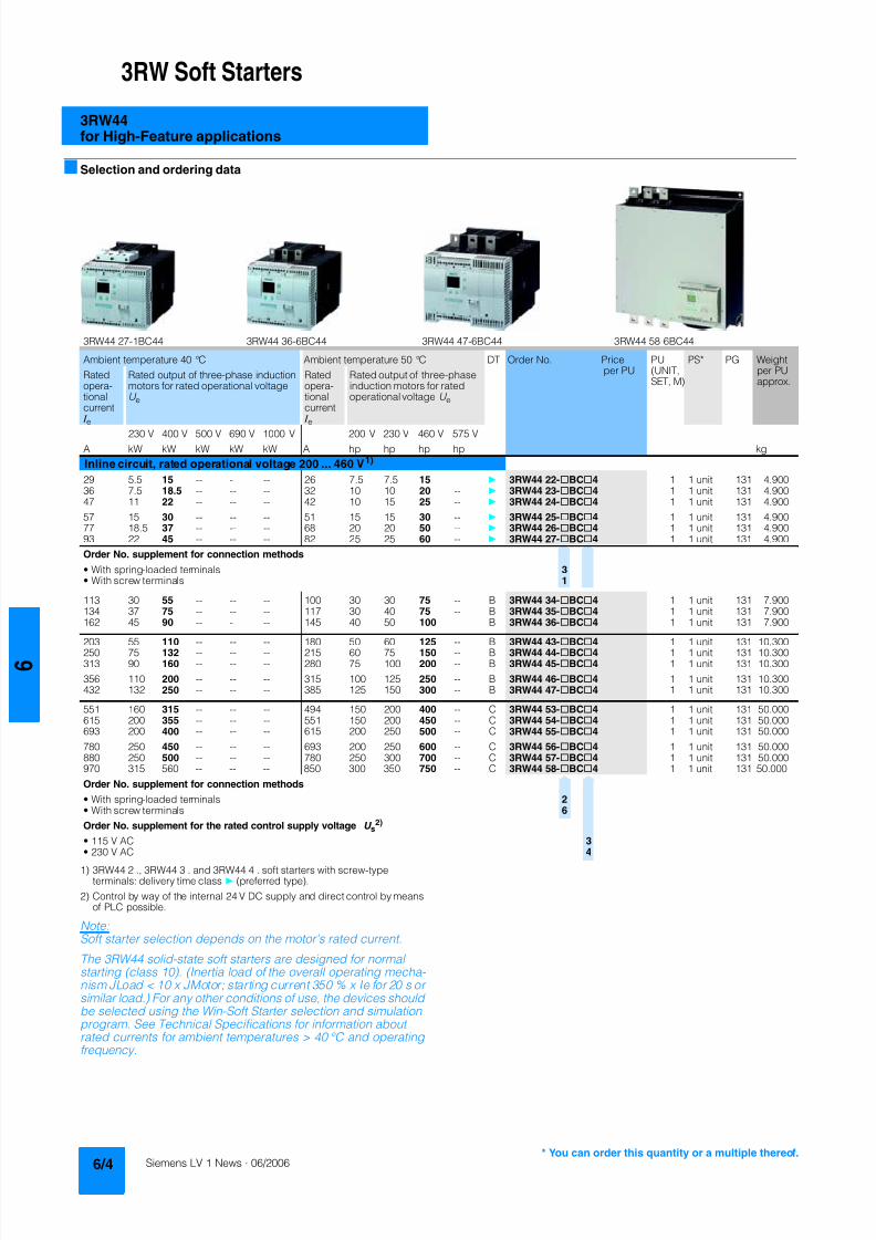
8122019 Arr Estado Solido
httpslidepdfcomreaderfullarr-estado-solido 840
3RW Soft Starters
3RW44for High-Feature applications
Selection and ordering data
1) 3RW44 2 3RW44 3 and 3RW44 4 soft starters with screw-typeterminals delivery time class (preferred type)
2) Control by way of the internal 24 V DC supply and direct control by meansof PLC possible
NoteSoft starter selection depends on the motors rated current
The 3RW44 solid-state soft starters are designed for normalstarting (class 10) (Inertia load of the overall operating mecha- nism JLoad lt 10 x JMotor starting current 350 x Ie for 20 s orsimilar load) For any other conditions of use the devices shouldbe selected using the Win-Soft Starter selection and simulationprogram See Technical Specifications for information aboutrated currents for ambient temperatures gt 40 degC and operatingfrequency
3RW44 27-1BC44 3RW44 36-6BC44 3RW44 47-6BC44 3RW44 58-6BC44
Ambient temperature 40 degC Ambient temperature 50 degC DT Order No Priceper PU
PU(UNITSET M)
PS PG Weightper PUapprox
Ratedopera-tionalcurrent I e
Rated output of three-phase inductionmotors for rated operational voltageU e
Ratedopera-tionalcurrent I e
Rated output of three-phaseinduction motors for ratedoperational voltage U e
230 V 400 V 500 V 690 V 1000 V 200 V 230 V 460 V 575 V
A kW kW kW kW kW A hp hp hp hp kg
Inline circuit rated operational voltage 200 460 V1)
29 55 15 -- -- -- 26 75 75 15 -- 3RW44 22-BC4 1 1 unit 131 490036 75 185 -- -- -- 32 10 10 20 -- 3RW44 23-BC4 1 1 unit 131 490047 11 22 -- -- -- 42 10 15 25 -- 3RW44 24-BC4 1 1 unit 131 4900
57 15 30 -- -- -- 51 15 15 30 -- 3RW44 25-BC4 1 1 unit 131 490077 185 37 -- -- -- 68 20 20 50 -- 3RW44 26-BC4 1 1 unit 131 490093 22 45 -- -- -- 82 25 25 60 -- 3RW44 27-BC4 1 1 unit 131 4900
Order No supplement for connection methods
bull With spring-loaded terminals 3bull With screw terminals 1
113 30 55 -- -- -- 100 30 30 75 -- B 3RW44 34-BC4 1 1 unit 131 7900134 37 75 -- -- -- 117 30 40 75 -- B 3RW44 35-BC4 1 1 unit 131 7900162 45 90 -- -- -- 145 40 50 100 -- B 3RW44 36-BC4 1 1 unit 131 7900
203 55 110 -- -- -- 180 50 60 125 -- B 3RW44 43-BC4 1 1 unit 131 10300250 75 132 -- -- -- 215 60 75 150 -- B 3RW44 44-BC4 1 1 unit 131 10300313 90 160 -- -- -- 280 75 100 200 -- B 3RW44 45-BC4 1 1 unit 131 10300
356 110 200 -- -- -- 315 100 125 250 -- B 3RW44 46-BC4 1 1 unit 131 10300432 132 250 -- -- -- 385 125 150 300 -- B 3RW44 47-BC4 1 1 unit 131 10300
551 160 315 -- -- -- 494 150 200 400 -- C 3RW44 53-BC4 1 1 unit 131 50000615 200 355 -- -- -- 551 150 200 450 -- C 3RW44 54-BC4 1 1 unit 131 50000693 200 400 -- -- -- 615 200 250 500 -- C 3RW44 55-BC4 1 1 unit 131 50000
780 250 450 -- -- -- 693 200 250 600 -- C 3RW44 56-BC4 1 1 unit 131 50000880 250 500 -- -- -- 780 250 300 700 -- C 3RW44 57-BC4 1 1 unit 131 50000970 315 560 -- -- -- 850 300 350 750 -- C 3RW44 58-BC4 1 1 unit 131 50000
Order No supplement for connection methods
bull With spring-loaded terminals 2bull With screw terminals 6
Order No supplement for the rated control supply voltage U s2)
bull 115 V AC 3bull 230 V AC 4
8122019 Arr Estado Solido
httpslidepdfcomreaderfullarr-estado-solido 940
3RW Soft Starters
3RW44for High-Feature applications
1) 3RW44 2 3RW44 3 and 3RW44 4 soft starters with screw-typeterminals delivery time class A
2) Control by way of the internal 24 V DC supply and direct control by meansof PLC possible
NoteSoft starter selection depends on the motors rated current
The 3RW44 solid-state soft starters are designed for normalstarting (class 10) (Inertia load of the overall operating mecha-nism J Load lt 10 x J Motor starting current 350 x I e for 20 s orsimilar load) For any other conditions of use the devices shouldbe selected using the Win-Soft Starter selection and simulationprogram See Technical Specifications for information aboutrated currents for ambient temperatures gt 40 degC and operating
frequency
Ambient temperature 40 degC Ambient temperature 50 degC DT Order No Priceper PU
PU(UNITSET M)
PS PG Weightper PUapprox
Ratedopera-
tionalcurrent I e
Rated output of three-phaseinduction motors for rated operational
voltage U e
Ratedopera-
tionalcurrent I e
Rated output of three-phaseinduction motors for rated
operational voltage U e
230 V 400 V 500 V 690 V 1000 V 200 V 230 V 460 V 575 V
A kW kW kW kW kW A hp hp hp hp kg
Inline circuit rated operational voltage 400 600 V1)
29 -- 15 185 -- -- 26 -- -- 15 20 A 3RW44 22-BC5 1 1 unit 131 490036 -- 185 22 -- -- 32 -- -- 20 25 A 3RW44 23-BC5 1 1 unit 131 490047 -- 22 30 -- -- 42 -- -- 25 30 A 3RW44 24-BC5 1 1 unit 131 4900
57 -- 30 37 -- -- 51 -- -- 30 40 A 3RW44 25-BC5 1 1 unit 131 490077 -- 37 45 -- -- 68 -- -- 50 50 A 3RW44 26-BC5 1 1 unit 131 490093 -- 45 55 -- -- 82 -- -- 60 75 A 3RW44 27-BC5 1 1 unit 131 4900
Order No supplement for connection methods
bull With spring-loaded terminals 3bull With screw terminals 1
113 -- 55 75 -- -- 100 -- -- 75 75 B 3RW44 34-BC5 1 1 unit 131 7900134 -- 75 90 -- -- 117 -- -- 75 100 B 3RW44 35-BC5 1 1 unit 131 7900
162 -- 90 110 -- -- 145 -- -- 100 125 B 3RW44 36-BC5 1 1 unit 131 7900
203 -- 110 132 -- -- 180 -- -- 125 150 B 3RW44 43-BC5 1 1 unit 131 10300250 -- 132 160 -- -- 215 -- -- 150 200 B 3RW44 44-BC5 1 1 unit 131 10300313 -- 160 200 -- -- 280 -- -- 200 250 B 3RW44 45-BC5 1 1 unit 131 10300
356 -- 200 250 -- -- 315 -- -- 250 300 B 3RW44 46-BC5 1 1 unit 131 10300432 -- 250 315 -- -- 385 -- -- 300 400 B 3RW44 47-BC5 1 1 unit 131 10300
551 -- 315 355 -- -- 494 -- -- 400 500 C 3RW44 53-BC5 1 1 unit 131 50000615 -- 355 400 -- -- 551 -- -- 450 600 C 3RW44 54-BC5 1 1 unit 131 50000693 -- 400 500 -- -- 615 -- -- 500 700 C 3RW44 55-BC5 1 1 unit 131 50000
780 -- 450 560 -- -- 693 -- -- 600 750 C 3RW44 56-BC5 1 1 unit 131 50000880 -- 500 630 -- -- 780 -- -- 700 850 C 3RW44 57-BC5 1 1 unit 131 50000970 -- 560 710 -- -- 850 -- -- 750 950 C 3RW44 58-BC5 1 1 unit 131 50000
Order No supplement for connection methods
bull With spring-loaded terminals 2bull With screw terminals 6
Order No supplement for the rated control supply voltage U s2)
bull 115 V AC 3bull 230 V AC 4
You can order this quantity or a multiple thereof
8122019 Arr Estado Solido
httpslidepdfcomreaderfullarr-estado-solido 1040
3RW Soft Starters
3RW44for High-Feature applications
1) Control by way of the internal 24 V DC supply and direct control by meansof PLC possible
NoteSoft starter selection depends on the motors rated current
The 3RW44 solid-state soft starters are designed for normalstarting (class 10) (Inertia load of the overall operating mecha- nism J Load lt 10 x J Motor starting current 350 x I e for 20 s orsimilar load) For any other conditions of use the devices shouldbe selected using the Win-Soft Starter selection and simulationprogram See Technical Specifications for information aboutrated currents for ambient temperatures gt 40 degC and operatingfrequency
Ambient temperature 40 degC Ambient temperature 50 degC DT Order No Priceper PU
PU(UNITSET M)
PS PG Weightper PUapprox
Ratedopera-
tionalcurrent I e
Rated output of three-phaseinduction motors for rated operational
voltage U e
Ratedopera-
tionalcurrent I e
Rated output of three-phaseinduction motors for rated
operational voltage U e
230 V 400 V 500 V 690 V 1000 V 200 V 230 V 460 V 575 V
A kW kW kW kW kW A hp hp hp hp kg
Inline circuit rated operational voltage 400 690 V
29 -- 15 185 30 -- 26 -- -- 15 20 B 3RW44 22-BC6 1 1 unit 131 490036 -- 185 22 37 -- 32 -- -- 20 25 B 3RW44 23-BC6 1 1 unit 131 490047 -- 22 30 45 -- 42 -- -- 25 30 B 3RW44 24-BC6 1 1 unit 131 4900
57 -- 30 37 55 -- 51 -- -- 30 40 B 3RW44 25-BC6 1 1 unit 131 490077 -- 37 45 75 -- 68 -- -- 50 50 B 3RW44 26-BC6 1 1 unit 131 490093 -- 45 55 90 -- 82 -- -- 60 75 B 3RW44 27-BC6 1 1 unit 131 4900
Order No supplement for connection methods
bull With spring-loaded terminals 3bull With screw terminals 1
113 -- 55 75 110 -- 100 -- -- 75 75 B 3RW44 34-BC6 1 1 unit 131 7900134 -- 75 90 132 -- 117 -- -- 75 100 B 3RW44 35-BC6 1 1 unit 131 7900
162 -- 90 110 160 -- 145 -- -- 100 125 B 3RW44 36-BC6 1 1 unit 131 7900
203 -- 110 132 200 -- 180 -- -- 125 150 B 3RW44 43-BC6 1 1 unit 131 10300250 -- 132 160 250 -- 215 -- -- 150 200 B 3RW44 44-BC6 1 1 unit 131 10300313 -- 160 200 315 -- 280 -- -- 200 250 B 3RW44 45-BC6 1 1 unit 131 10300
356 -- 200 250 355 -- 315 -- -- 250 300 B 3RW44 46-BC6 1 1 unit 131 10300432 -- 250 315 400 -- 385 -- -- 300 400 B 3RW44 47-BC6 1 1 unit 131 10300
551 -- 315 355 560 -- 494 -- -- 400 500 C 3RW44 53-BC6 1 1 unit 131 50000615 -- 355 400 630 -- 551 -- -- 450 600 C 3RW44 54-BC6 1 1 unit 131 50000693 -- 400 500 710 -- 615 -- -- 500 700 C 3RW44 55-BC6 1 1 unit 131 50000
780 -- 450 560 800 -- 693 -- -- 600 750 C 3RW44 56-BC6 1 1 unit 131 50000880 -- 500 630 900 -- 780 -- -- 700 850 C 3RW44 57-BC6 1 1 unit 131 50000970 -- 560 710 1000 -- 850 -- -- 750 950 C 3RW44 58-BC6 1 1 unit 131 50000
Order No supplement for connection methods
bull With spring-loaded terminals 2bull With screw terminals 6
Order No supplement for the rated control supply voltage U s1)
bull 115 V AC 3bull 230 V AC 4
8122019 Arr Estado Solido
httpslidepdfcomreaderfullarr-estado-solido 1140
3RW Soft Starters
3RW44for High-Feature applications
1) In the selection table the unit rated operational current I e refers to the
three-phase motors rated operational current in the inside-delta circuitThe actual current of the unit is approx 58 of this value
2) 3RW44 2 3RW44 3 and 3RW44 4 soft starters with screw-typeterminals delivery time class (preferred type)
3) Control by way of the internal 24 V DC supply and direct control by meansof PLC possible
NoteSoft starter selection depends on the motors rated current
The 3RW44 solid-state soft starters are designed for normalstarting (class 10) (Inertia load of the overall operatingmechanism JLoad lt 10 x JMotor starting current 350 x Ie for20 s or similar load) For any other conditions of use the devicesshould be selected using the Win-Soft Starter selection andsimulation program See Technical Specifications for informationabout rated currents for ambient temperatures gt 40 degC andoperating frequency
3RW44 27-1BC44 3RW44 36-6BC44 3RW44 47-6BC44 3RW44 58-6BC44
Ambient temperature 40 degC Ambient temperature 50 degC DT Order No Priceper PU
PU(UNITSET M)
PS PG Weightper PUapprox
Ratedopera-tionalcurrent I e
1)
Rated output of three-phase inductionmotors for rated operational voltageU e
Ratedopera-tionalcurrent I e
Rated output of three-phaseinduction motors for ratedoperational voltage U e
230 V 400 V 500 V 690 V 1000 V 200 V 230 V 460 V 575 V
A kW kW kW kW kW A hp hp hp hp kgInside-delta circuits rated operational voltage 200 460 V2)
50 15 22 -- -- -- 45 10 15 30 -- B 3RW44 22-BC4 1 1 unit 131 490062 185 30 -- -- -- 55 15 20 40 -- B 3RW44 23-BC4 1 1 unit 131 490081 22 45 -- -- -- 73 20 25 50 -- B 3RW44 24-BC4 1 1 unit 131 4900
99 30 55 -- -- -- 88 25 30 60 -- B 3RW44 25-BC4 1 1 unit 131 4900133 37 75 -- -- -- 118 30 40 75 -- B 3RW44 26-BC4 1 1 unit 131 4900161 45 90 -- -- -- 142 40 50 100 -- B 3RW44 27-BC4 1 1 unit 131 4900
Order No supplement for connection methods
bull With spring-loaded terminals 3bull With screw terminals 1
196 55 110 -- -- -- 173 50 60 125 -- B 3RW44 34-BC4 1 1 unit 131 7900232 75 132 -- -- -- 203 60 75 150 -- B 3RW44 35-BC4 1 1 unit 131 7900281 90 160 -- -- -- 251 75 100 200 -- B 3RW44 36-BC4 1 1 unit 131 7900
352 110 200 -- -- -- 312 100 125 250 -- B 3RW44 43-BC4 1 1 unit 131 10300433 132 250 -- -- -- 372 125 150 300 -- B 3RW44 44-BC4 1 1 unit 131 10300542 160 315 -- -- -- 485 150 200 400 -- B 3RW44 45-BC4 1 1 unit 131 10300
617 200 355 -- -- -- 546 150 200 450 -- B 3RW44 46-BC4 1 1 unit 131 10300748 250 400 -- -- -- 667 200 250 600 -- B 3RW44 47-BC4 1 1 unit 131 10300
954 315 560 -- -- -- 856 300 350 750 -- C 3RW44 53-BC4 1 1 unit 131 500001065 355 630 -- -- -- 954 350 400 850 -- C 3RW44 54-BC4 1 1 unit 131 500001200 400 710 -- -- -- 1065 350 450 950 -- C 3RW44 55-BC4 1 1 unit 131 50000
1351 450 800 -- -- -- 1200 450 500 1050 -- C 3RW44 56-BC4 1 1 unit 131 500001524 500 900 -- -- -- 1351 450 600 1200 -- C 3RW44 57-BC4 1 1 unit 131 500001680 560 1000 -- -- -- 1472 550 650 1300 -- C 3RW44 58-BC4 1 1 unit 131 50000
Order No supplement for connection methods
bull With spring-loaded terminals 2bull With screw terminals 6
Order No supplement for the rated control supply voltage U s3)
bull 115 V AC 3bull 230 V AC 4
You can order this quantity or a multiple thereof
8122019 Arr Estado Solido
httpslidepdfcomreaderfullarr-estado-solido 1240
3RW Soft Starters
3RW44for High-Feature applications
1) In the selection table the unit rated operational current I e refers to thethree-phase motors rated operational current in the inside-delta circuitThe actual current of the unit is approx 58 of this value
2) 3RW44 2 3RW44 3 and 3RW44 4 soft starters with screw-typeterminals delivery time class A
3) Control by way of the internal 24 V DC supply and direct control by meansof PLC possible
Accessories
NoteSoft starter selection depends on the motors rated current
The 3RW44 solid-state soft starters are designed for normalstarting (class 10) (Inertia load of the overall operatingmechanism J Load lt 10 x J Motor starting current 350 x I e for20 s or similar load) For any other conditions of use the devicesshould be selected using the Win-Soft Starter selection andsimulation program See Technical Specifications for informationabout rated currents for ambient temperatures gt 40 degC andoperating frequency
Ambient temperature 40 degC Ambient temperature 50 degC DT Order No Priceper PU
PU(UNITSET M)
PS PG Weightper PUapprox
Ratedopera-
tionalcurrent I e
1)
Rated output of three-phaseinduction motors for rated opera-
tional voltage U e
Ratedopera-
tionalcurrent I e
Rated output of three-phaseinduction motors for rated
operational voltage U e
230 V 400 V 500 V 690 V 1000 V 200 V 230 V 460 V 575 V
A kW kW kW kW kW A hp hp hp hp kg
Inside-delta circuits rated operational voltage 400 600 V2)
50 -- 22 30 -- -- 45 -- -- 30 40 B 3RW44 22-BC5 1 1 unit 131 490062 -- 30 37 -- -- 55 -- -- 40 50 B 3RW44 23-BC5 1 1 unit 131 490081 -- 45 45 -- -- 73 -- -- 50 60 B 3RW44 24-BC5 1 1 unit 131 4900
99 -- 55 55 -- -- 88 -- -- 60 75 B 3RW44 25-BC5 1 1 unit 131 4900133 -- 75 90 -- -- 118 -- -- 75 100 B 3RW44 26-BC5 1 1 unit 131 4900161 -- 90 110 -- -- 142 -- -- 100 125 B 3RW44 27-BC5 1 1 unit 131 4900
Order No supplement for connection methods
bull With spring-loaded terminals 3bull With screw terminals 1
196 -- 110 132 -- -- 173 -- -- 125 150 B 3RW44 34-BC5 1 1 unit 131 7900232 -- 132 160 -- -- 203 -- -- 150 200 B 3RW44 35-BC5 1 1 unit 131 7900
281 -- 160 200 -- -- 251 -- -- 200 250 B 3RW44 36-BC5 1 1 unit 131 7900
352 -- 200 250 -- -- 312 -- -- 250 300 B 3RW44 43-BC5 1 1 unit 131 10300433 -- 250 315 -- -- 372 -- -- 300 350 B 3RW44 44-BC5 1 1 unit 131 10300542 -- 315 355 -- -- 485 -- -- 400 500 B 3RW44 45-BC5 1 1 unit 131 10300
617 -- 355 450 -- -- 546 -- -- 450 600 B 3RW44 46-BC5 1 1 unit 131 10300748 -- 400 500 -- -- 667 -- -- 600 750 B 3RW44 47-BC5 1 1 unit 131 10300
954 -- 560 630 -- -- 856 -- -- 750 950 C 3RW44 53-BC5 1 1 unit 131 500001065 -- 630 710 -- -- 954 -- -- 850 1050 C 3RW44 54-BC5 1 1 unit 131 500001200 -- 710 800 -- -- 1065 -- -- 950 1200 C 3RW44 55-BC5 1 1 unit 131 50000
1351 -- 800 900 -- -- 1200 -- -- 1050 1350 C 3RW44 56-BC5 1 1 unit 131 500001524 -- 900 1000 -- -- 1351 -- -- 1200 1500 C 3RW44 57-BC5 1 1 unit 131 500001680 -- 1000 1200 -- -- 1472 -- -- 1300 1650 C 3RW44 58-BC5 1 1 unit 131 50000
Order No supplement for connection methods
bull With spring-loaded terminals 2bull With screw terminals 6
Order No supplement for the rated control supply voltage U s3)
bull 115 V AC 3bull 230 V AC 4
Forsoft starters Version DT Order No Priceper PU PU(UNITSET M)
PS PG Weightper PUapprox
Type kg
Soft Starter ES 2006 PC communication program
Soft Starter ES 2006 Smart
Parameterization and service software forSIRIUS 3RW44 soft starters for parameterizingthrough the system interface on the deviceExecutes on PCPG under Windows 2000XPwithout PC cableType of supply CD single license
3ZS1 313-1CC10-0YA0 1 1 unit 131 0230
3ZS1 313-1CC10-0YA0 Soft Starter ES 2006 Professional
Parameterization and service software forSIRIUS 3RW44 soft starters for parameterizingthrough the system interface on the device andPROFIBUS DP interface (PROFIBUS as optional commu-nication module necessary)Executes on PCPG under Windows 2000XPwithout PC cableType of supply CD single license
A 3ZS1 313-2CC10-0YA0 1 1 unit 131 0230
8122019 Arr Estado Solido
httpslidepdfcomreaderfullarr-estado-solido 1340
3RW Soft Starters
3RW44for High-Feature applications
Spare parts
Forsoft starters
Version DT Order No Priceper PU
PU(UNITSET M)
PS PG Weightper PUapprox
Type kg
PC cables
For PCPG communication with SIRIUS 3RW44soft starters
through the system interface for connecting tothe serial interface of the PCPG
B 3UF7 940-0AA00-0 1 1 unit 131 0150
Box terminal blocks for soft starters
Box terminal blocks
3RW44 2 Included in del ivery
3RW44 3 bull Up to 70 mm2 3RT19 55-4G 1 1 unit 101 0237
bull Up to 120 mm2 3RT19 56-4G 1 1 unit 101 0270
3RW44 3 bull Up to 240 mm2 3RT19 66-4G 1 1 unit 101 0676
PROFIBUS Communication moduleModule to be plugged into the soft starter to connect thesoft starter to the PROFIBUS net
A 3RW4 900-0KC00 1 1 unit 131 0320
External display and operation module
to show and operate the fonctions supplied by the softstarter via externally mounted display and operationmodule(for example in the cubicle door)
A 3RW4 900-0AC00 1 1 unit 131 0320
Connection cable
from serial interface of 3RW44 soft starter to external dis-play and operation modulebull Length 05 m flat B 3UF7 932-0AA00-0 1 1 unit 131 0020bull Length 05 m round A 3UF7 932-0BA00-0 1 1 unit 131 0050bull Length10 m round A 3UF7 937-0BA00-0 1 1 unit 131 0100bull Length25 m round A 3UF7 933-0BA00-0 1 1 unit 131 0150
Covers for soft starters
Terminal covers for box terminals
Additional touch protection to be fitted at the boxterminals (2 units required per device)
3RW44 2 and3RW44 3
3RT19 56-4EA2 1 1 unit 101 0028
3RW44 4 3RT19 66-4EA2 1 1 unit 101 0038
Terminal covers for cable lugs and busbarconnections
3RW44 2 and3RW44 3
3RT19 56-4EA1 1 1 unit 101 0067
3RW44 4 3RT19 66-4EA1 1 1 unit 101 0124
Forsoft starters
Version DT Order No Priceper PU
PU(UNITSET M)
PS PG Weightper PUapprox
Type kg
Fans
Fans
3RW44 2 and3RW44 3
115 VAC 3RW49 36-8VX30 1 1 unit 131 0300230 VAC 3RW49 36-8VX40 1 1 unit 131 0300
3RW44 4 115 V AC 3RW49 47-8VX30 1 1 unit 131 0500230 VAC 3RW49 47-8VX40 1 1 unit 131 0500
3RW44 5 115 V AC 3RW49 57-8VX30 1 1 unit 131 0800230 VAC 3RW49 57-8VX40 1 1 unit 131 0800
You can order this quantity or a multiple thereof
8122019 Arr Estado Solido
httpslidepdfcomreaderfullarr-estado-solido 1440
3RW Soft Starters
3RW44for High-Feature applications
Function
Equipped with modern ergonomic user prompting theSIRIUS 3RW44 soft starters can be commissioned quickly and
easily using a keypad and a menu-prompted multi-line displaywith background lighting Motor starting and deceleration areoptimized quickly easily and safely with just a few settings in aselectable language Four-key operation and plain-text displaysfor each menu point guarantee full clarity at every moment of theparameterization and operation Measurement values and oper-ating values as well as warning messages and fault indicationsare output continuously on the front panel during operation andwhen control voltage is applied An external display and opera-tor module can be connected by means of a connecting cableto the soft starter thus enabling active indications and the like tobe read directly from the control cabinet door
The SIRIUS 3RW44 soft starters are equipped with optimumfunctionality An integral bypass contact system reduces thepower loss of the soft starter during operation This reliablyprevents heating of the switchgear environment TheSIRIUS 3RW44 soft starters have internal intrinsic deviceprotection This prevents thermal overloading of the powersections thyristors eg due to unacceptably high closingoperations
Wiring work for installing an additional motor overload relay is nolonger needed as the SIRIUS 3RW44 soft starters perform thisfunction too In addition they offer adjustable trip classes and athermistor motor protection function As an option the thyristorscan also be protected by SITOR semi-conductor fuses fromshort-circuiting And even inrush current peaks are reliablyavoided thanks to adjustable current limiting
As a further option the SIRIUS 3RW44 soft starters can beupgraded with a PROFIBUS DP module Thanks to their commu-nication capability and their programmable control inputs andrelay outputs the SIRIUS 3RW44 soft starters can be very easily
and quickly integrated in higher-level controllersIn addition a creep speed function is available for positioningand setting jobs With this function the motor can be controlledin both directions of rotation with reduced torque and an adjust-able low speed
On the other hand the SIRIUS 3RW44 soft starters offer a newcombined DC braking function for the fast stopping of drivingloads
Highlights bull Soft starting with breakaway pulse torque control or voltage
ramp and adjustable torque or current limiting as well as anycombination of these depending on load type
bull Integrated bypass contact system to minimize dissipatedpower
bull Various setting options for the starting parameters such asstarting torque starting voltage ramp-up and ramp-downtime and much more in three separate parameter sets
bull Start-up detectionbull Inside-delta circuit for savings in terms of size and equipment
costsbull Various ramp-down modes selectable free ramp-down
torque-controlled pump stopping combined DC brakingbull Solid-state motor overload and intrinsic device protectionbull Thermistor motor protectionbull Keypad with a menu-controlled multi-line graphic display with
background lighting
bull Interface for communication with the PC for more accuratesetting of the parameters as well as for control and monitoringbull Simple adaptation to the motor feederbull Simple mounting and commissioningbull Display of operating states and fault signalsbull Connection to PROFIBUS with optional PROFIBUS DP modulebull External display and operator modulebull System voltages from 200 to 690 V 50 to 60 Hzbull Applicable up to 60 degC (derating from 40 degC)
8122019 Arr Estado Solido
httpslidepdfcomreaderfullarr-estado-solido 1540
3RW Soft Starters
3RW44for High-Feature applications
Technical specifications
Type 3RW44 -BC3 3RW44 -BC4Terminal
Control electronics
Rated valuesRated control supply voltage A1A2PE V 115 AC 230 ACbull Tolerance -15+10 -15+10Rated control supply current STANDBY mA 30 20
Rated control supply current ONbull 3RW44 2 mA 300 170bull 3RW44 3 mA 500 250bull 3RW44 4 mA 750 400bull 3RW44 5 mA 450 200
Maximum current (pickup bypass)bull 3RW44 2 mA 1000 500bull 3RW44 3 mA 2500 1250bull 3RW44 4 mA 6000 3000bull 3RW44 5 mA 4500 2500
Rated frequency Hz 50 60 50 60bull Tolerance plusmn10 plusmn10
Type 3RW44 Terminal Factory presetting
Control electronics
Control inputsInput 1 IN1 Start motor right parameter set 1Input 2 IN2 No actionInput 3 IN3 No actionInput 4 IN4 Trip reset
Supply L+L-bull Rated operational current mA Approx 10 per input to DIN 19240bull Rated operational voltage L+ Internal voltage 24 V DC from inter-
nal supply through terminal L+ toIN1 IN4 Maximum load at L+approx 55 mA
L- External voltage DC external voltage(to DIN19240) through terminals
L- and IN1 IN4(min 12 V DC max 30 V DC)
Thermistor motor protection inputInput T1T2 PTC type A or Thermoclick Deactivated
Relay outputs (floating auxiliary contacts)Output 1 1314 ON periodOutput 2 2324 No actionOutput 3 3334 No actionOutput 4 959698 Group fault
Switching capacity of the relay outputs230 VAC-15 A 3 at 240 V24 VDC-13 A 1 at 24 VProtection against overvoltages Protection by means of Varistor through relay contactShort-circuit protection 4 A gLgG operational class
6 A quick (fuse is not included in scope of supply)
Protective functions
Motor protection functionsTrips in the event of Thermal overloading of the motor
Trip class to IEC 60947-4-1 Class 510152030 10Phase failure sensitivity gt 40
Overload warning yesReset and recovery ManualAutomatic ManualReset option after tripping ManualAutomatic ManualRecovery time min 1 30 1
Device protection functionsTrips in the event of Thermal overloading of the thyristorsReset option after tripping ManualAutomatic ManualRecovery time min 05
8122019 Arr Estado Solido
httpslidepdfcomreaderfullarr-estado-solido 1640
3RW Soft Starters
3RW44for High-Feature applications
Type 3RW44 Factory presetting
Control times and parameters
Control timesClosing delay (with connected control voltage) ms lt 50Closing delay (automatic mode) ms lt 4000Recovery time (closing command in active ramp-down) ms lt 100
Mains failure bridging timeControl supply voltage ms 100
Mains failure response timeLoad current circuit ms 100
Reclosing lockout after overload tripMotor protection trip min 1 30 1Device protection trip s 30
Setting options for startingVoltage ramp for starting voltage 20 100 30Torque control for starting torque 20 100 50Torque control for limit torque 20 200 150
Starting time s 0 360 20Maximum starting time s 1 1000 DeactivatedCurrent limit value 125 550 450
Breakaway voltage 40 100 80Breakaway time s 0 2 DeactivatedMotor heat output 0 100 0
Creep mode LeftRight runningSpeed factor as function of rated speed (n = n rated factor) 3 21 7Creep torque (reference variable depends on the motor used but isalways smaller than the rated torque of the motor)
20 100 50
Setting options for ramp-downTorque control for stopping torque 10 100 10Ramp-down time s 0 360 10Dynamic braking torque 20 100 50DC braking torque 20 100 50
Operating indicationsTest voltageTest mains phasesReady to start
Start active
Motor runningRamp-down active
Warningserror signalsMains voltage missingLeading-edge phase error
Phase failurebull L1bull L2bull L3
Missing load phasebull T1bull T2bull T3
Failurebull Contact element 1 (thyristor)bull Contact element 2 (thyristor)bull Contact element 3 (thyristor)
Flash memory faulty
Supply voltagebull Below 75 bull Below 85 bull Over 110
Current unbalance exceededThermal motor model overload
Prewarning limit exceededbull Motor heatingbull Time-related trip reserve
Bypass elements defectiveMains voltage too high
Device not namedWrong naming versionCurrent range exceeded
Motor blocking ndash shutdownCurrent limit exceeded
Power section
bull Overheatedbull OvertemperatureEmergency active
8122019 Arr Estado Solido
httpslidepdfcomreaderfullarr-estado-solido 1740
3RW Soft Starters
3RW44for High-Feature applications
1) Parameter motor left possible only in conjunction with creep mode
Type 3RW44 Factory presetting
Control times and parameters
Warningserror signals (contd)Temperature sensorbull Overloadbull Open-circuitbull Short-circuit
Ground faultbull Detectedbull Shutdown
Connection abort in manual modeMax number of starts exceeded I e limit value overshootundershoot
Cooling timebull Motor activebull Switch block active
Heat sink sensorbull Open-circuitbull Short-circuit
Quick-stop functionSwitch block faulty I e class setting not permissible
Control inputsInput 1 Motor right parameter set 1Input 2 No actionInput 3 No actionInput 4 Trip reset
Parameterizing options for control inputs 1 4 No actionLocal manual modeEmergency startCreep speedQuick-stopTrip reset
Motor right parameter set 1Motor left parameter set 11) Motor right parameter set 2Motor left parameter set 21) Motor right parameter set 3Motor left parameter set 31)
Relay outputsOutput 1 ON periodOutput 2 No actionOutput 3 No actionOutput 4 Group fault
Parameterizing options for relay outputs 1 3 No actionPAA output 1PAA output 2
Input 1Input 2Input 3Input 4
Ramp-upOperationBypassRamp-downON periodCommand motor on
FanDC braking contactor
Group warningGroup faultBus faultDevice error
Power onReady to start
Motor temperature sensors Deactivated DeactivatedThermoclickPTC type A
8122019 Arr Estado Solido
httpslidepdfcomreaderfullarr-estado-solido 1840
3RW Soft Starters
3RW44for High-Feature applications
1) Current limit on soft starter set to 350 I M
2) For intermittent duty S4 with ON period = 70 T u = 40 degC stand-aloneinstallation vertical The quoted operating frequencies do not apply forautomatic mode
3) Maximum adjustable rated motor current I M dependent on CLASS setting
Type 3RW44 -BC4 3RW44 -BC5 3RW44 -BC6
Power electronics
Rated operational voltage for inline circuit V 200 460 AC 400 600 AC 400 690 AC
Tolerance -15+10 -15+10 -15+10Rated operational voltage for inside-delta circuit V 200 460 AC 400 600 AC 400 600 ACTolerance -15+10 -15+10 -15+10
Rated frequency Hz 50 60Tolerance plusmn10
Continuous operation at 40 degC ( of I e) 115
Minimum load ( of set motor current I M) 8
Maximum conductor length between soft starter and motor m 200
Permissible installation height m 5000 (derating from 1000 see characteristics) higher on request
Permissible mounting position
Permissible ambient temperatureOperation degC 0 +60 (derating from +40)Storage degC -25 +80
Degree of protection IP00
Type 3RW44 22 3RW44 23 3RW44 24 3RW44 25 3RW44 26 3RW44 27
Power electronics
Rated operational current I e 29 36 47 57 77 93
Load rating with rated operational current I ebull Acc to IEC and ULCSA for individual mounting
at 405060 degC AC-53a A 292623 363229 474237 575145 776859 938272
Smallest adjustable rated motor current I Mfor the motor overload protection
A 5 7 9 11 15 18
Power lossbull In operation after completed ramp-up with uninterrupted rated
operational current (40 degC) approx W 8 10 32 36 45 55bull During starting with current limit set to 350 I M (40 degC) W 400 470 600 725 940 1160
Permissible rated motor current and starts per hour
bull Normal starting (Class 5)- Rated motor current I M
1) starting time 5 s A 29 36 47 57 77 93- Starts per hour2) 1h 41 34 41 41 41 41
- Rated motor current I M1)3) starting time 10 s A 29 36 47 57 77 93
- Starts per hour2) 1h 20 15 20 20 20 20
bull Normal starting (Class 10)- Rated motor current I M
1) starting time 10 s A 29 36 47 57 77 93- Starts per hour2) 1h 20 15 20 20 20 20
- Rated motor current I M1)3) starting time 20 s A 29 36 47 57 77 93
- Starts per hour2) 1h 10 6 10 10 8 8
bull Normal starting (Class 15)- Rated motor current I M
1) starting time 15 s A 29 36 47 57 77 93- Starts per hour2) 1h 13 9 13 13 13 13
- Rated motor current I M1)3) starting time 30 s A 29 36 47 57 77 93
- Starts per hour2) 1h 6 4 6 6 6 6
bull For heavy starting (Class 20)- Rated motor current I M
1) starting time 20 s A 29 36 47 57 73 88- Starts per hour2) 1h 10 6 10 10 10 10
- Rated motor current I M1)3) starting time 40 s A 29 36 47 57 73 88
- Starts per hour2) 1h 4 2 4 5 18 08
bull For very heavy starting (Class 30)- Rated motor current I M
1) starting time 30 s A 29 36 44 57 65 77- Starts per hour2) 1h 6 4 6 6 6 6
- Rated motor current I M1)3) starting time 60 s A 29 36 44 57 65 77
- Starts per hour2) 1h 18 08 33 15 2 1
8122019 Arr Estado Solido
httpslidepdfcomreaderfullarr-estado-solido 1940
3RW Soft Starters
3RW44for High-Feature applications
1) Current limit on soft starter set to 350 I M
2) For intermittent duty S4 with ON period = 70 T u = 40 degC stand-aloneinstallation vertical The quoted operating frequencies do not apply forautomatic mode
3) Maximum adjustable rated motor current I M dependent on CLASS setting
Type 3RW44 34 3RW44 35 3RW44 36
Power electronics
Rated operational current I e 113 134 162
Load rating with rated operational current I ebull Acc to IEC and ULCSA for individual mounting AC-53a
- at 40 degC A 113 134 162- at 50 degC A 100 117 145- at 60 degC A 88 100 125
Smallest adjustable rated motor current I Mfor the motor overload protection
A 22 26 32
Power lossbull In operation after completed ramp-up with uninterrupted rated
operational current (40 degC) approx W 64 76 95bull During starting with current limit set to 350 I M (40 degC) W 1350 1700 2460
Permissible rated motor current and starts per hour
bull Normal starting (Class 5)- Rated motor current I M
1) starting time 5 s A 113 134 162- Starts per hour2) 1h 41 39 41
- Rated motor current I M1)3) starting time 10 s A 113 134 162
- Starts per hour2) 1h 20 15 20
bull Normal starting (Class 10)- Rated motor current I M
1) starting time 10 s A 113 134 162- Starts per hour2) 1h 20 15 20
- Rated motor current I M1)3) starting time 20 s A 113 134 162
- Starts per hour2) 1h 9 6 7
bull Normal starting (Class 15)- Rated motor current I M
1) starting time 15 s A 113 134 162- Starts per hour2) 1h 13 9 12
- Rated motor current I M1)3) starting time 30 s A 113 134 162
- Starts per hour2) 1h 6 6 1
bull For heavy starting (Class 20)- Rated motor current I M
1) starting time 20 s A 106 125 147- Starts per hour2) 1h 9 9 10
- Rated motor current I M1)3) starting time 40 s A 106 125 147
- Starts per hour2) 1h 15 2 1
bull For very heavy starting (Class 30)- Rated motor current I M
1) starting time 30 s A 91 110 120
- Starts per hour2) 1h 6 6 6- Rated motor current I M
1)3) starting time 60 s A 91 110 120- Starts per hour2) 1h 2 2 2
8122019 Arr Estado Solido
httpslidepdfcomreaderfullarr-estado-solido 2040
3RW Soft Starters
3RW44for High-Feature applications
1) Current limit on soft starter set to 350 I M
2) For intermittent duty S4 with ON period = 70 T u = 40 degC stand-aloneinstallation vertical The quoted operating frequencies do not apply forautomatic mode
3) Maximum adjustable rated motor current I M dependent on CLASS setting
Type 3RW44 43 3RW44 44 3RW44 45 3RW44 46 3RW44 47
Power electronics
Rated operational current I e 203 250 313 356 432
Load rating with rated operational current I ebull Acc to IEC and ULCSA for individual mounting AC-53a
- at 40 degC A 203 250 313 356 432- at 50 degC A 180 215 280 315 385- at 60 degC A 156 185 250 280 335
Smallest adjustable rated motor current I Mfor the motor overload protection
A 40 50 62 71 86
Power lossbull In operation after completed ramp-up with uninterrupted rated
operational current (40 degC) approx W 89 110 145 174 232bull During starting with current limit set to 350 I M (40 degC) W 3350 4000 4470 5350 5860
Permissible rated motor current and starts per hour
bull Normal starting (Class 5)- Rated motor current I M
1) starting time 5 s A 203 250 313 356 432- Starts per hour2) 1h 41 41 41 41 39
- Rated motor current I M1)3) starting time 10 s A 203 250 313 356 432
- Starts per hour2) 1h 20 20 19 17 16
bull Normal starting (Class 10)- Rated motor current I M
1) starting time 10 s A 203 250 313 356 432- Starts per hour2) 1h 20 20 19 17 16
- Rated motor current I M1)3) starting time 20 s A 203 250 313 356 432
- Starts per hour2) 1h 9 10 6 4 5
bull Normal starting (Class 15)- Rated motor current I M
1) starting time 15 s A 203 240 313 325 402- Starts per hour2) 1h 13 13 10 13 11
- Rated motor current I M1)3) starting time 30 s A 203 240 313 325 402
- Starts per hour2) 1h 3 6 1 2 1
bull For heavy starting (Class 20)- Rated motor current I M
1) starting time 20 s A 195 215 275 285 356- Starts per hour2) 1h 10 10 10 10 10
- Rated motor current I M1)3) starting time 40 s A 195 215 275 285 356
- Starts per hour2) 1h 1 5 1 3 1
bull For very heavy starting (Class 30)- Rated motor current I M
1) starting time 30 s A 162 180 220 240 285
- Starts per hour2) 1h 6 6 6 6 6- Rated motor current I M
1)3) starting time 60 s A 162 180 220 240 285- Starts per hour2) 1h 3 3 3 2 1
8122019 Arr Estado Solido
httpslidepdfcomreaderfullarr-estado-solido 2140
3RW Soft Starters
3RW44for High-Feature applications
1) Current limit on soft starter set to 350 I M
2) For intermittent duty S4 with ON period = 70 T u = 40 degC stand-aloneinstallation vertical The quoted operating frequencies do not apply forautomatic mode
3) Maximum adjustable rated motor current I M dependent on CLASS setting
Type 3RW44 53 3RW44 54 3RW44 55 3RW44 56 3RW44 57 3RW44 58
Power electronics
Rated operational current I e 551 615 693 780 880 970
Load rating with rated operational current I ebull Acc to IEC and ULCSA for individual mounting AC-53a
- at 40 degC A 551 615 693 780 880 970- at 50 degC A 494 551 615 693 780 850- at 60 degC A 438 489 551 615 693 760
Smallest adjustable rated motor current I Mfor the motor overload protection
A 110 123 138 156 176 194
Power lossbull In operation after completed ramp-up with uninterrupted rated
operational current (40 degC) approx W 159 186 220 214 250 270bull During starting with current limit set to 350 I M (40 degC) W 7020 8100 9500 11100 13100 15000
Permissible rated motor current and starts per hour
bull Normal starting (Class 5)- Rated motor current I M
1) starting time 5 s A 551 615 693 780 880 970- Starts per hour2) 1h 41 41 37 33 22 17
- Rated motor current I M1)3) starting time 10 s A 551 615 693 780 880 970
- Starts per hour2) 1h 20 20 16 13 8 5
bull Normal starting (Class 10)- Rated motor current I M
1) starting time 10 s A 551 615 693 780 880 970- Starts per hour2) 1h 20 20 16 13 8 5
- Rated motor current I M1)3) starting time 20 s A 551 615 693 780 880 970
- Starts per hour2) 1h 10 9 6 4 03 03
bull Normal starting (Class 15)- Rated motor current I M
1) starting time 15 s A 551 615 666 723 780 821- Starts per hour2) 1h 13 13 11 9 8 8
- Rated motor current I M1)3) starting time 30 s A 551 615 666 723 780 821
- Starts per hour2) 1h 6 4 3 1 04 05
bull For heavy starting (Class 20)- Rated motor current I M
1) starting time 20 s A 551 591 633 670 710 740- Starts per hour2) 1h 10 10 7 8 8 9
- Rated motor current I M1)3) starting time 40 s A 551 591 633 670 710 740
- Starts per hour2) 1h 4 2 1 1 04 1
bull For very heavy starting (Class 30)- Rated motor current I M
1) starting time 30 s A 500 525 551 575 600 630
- Starts per hour2) 1h 6 6 6 6 6 6- Rated motor current I M
1)3) starting time 60 s A 500 525 551 575 600 630- Starts per hour2) 1h 2 1 1 1 15 1
8122019 Arr Estado Solido
httpslidepdfcomreaderfullarr-estado-solido 2240
3RW Soft Starters
3RW44for High-Feature applications
1) When connecting cable lugs to DIN 46235 use 3RT19 56-4EA1 terminalcover for conductor cross-sections from 95 mmsup2 to ensure phase spacing
2) When connecting cable lugs to DIN 46234 the 3RT19 66-4EA1 terminalcover must be used for conductor cross-sections of 240 mmsup2 and more aswell as DIN 46235 for conductor cross-sections of 185 mmsup2 and more tokeep the phase clearance
Type 3RW44 2 3RW44 3 3RW44 4 3RW44 5
Conductor cross-sections
Screw
terminals
Main conductors
with box terminal 3RT19 55-4G (55 kW) 3RT19 66-4G
Front clampingpoint connected
bull Finely stranded with end sleeve mm2 16 70 70 240bull Finely stranded without end sleeve mm2 16 70 70 240bull Stranded mm2 16 70 95 300
bull Ribbon cable conductors(number x width x thickness)
mm min 3 x 9 x 08max 6 x 155 x 08
min 6 x 9 x 08max 20 x 24 x 05
bull AWG conductors solid or stranded AWG 6 20 30 600 kcmil
Rear clamping pointconnected
bull Finely stranded with end sleeve mm2 16 70 120 185bull Finely stranded without end sleeve mm2 16 70 120 185bull Stranded mm2 16 70 120 240
bull Ribbon cable conductors(number x width x thickness)
mm min 3 x 9 x 08max 6 x 155 x 08
min 6 x 9 x 08max 20 x 24 x 05
bull AWG conductors solid or stranded AWG 6 20 250 500 kcmil
Both clamping
points connected
bull Finely stranded with end sleeve mm2 max 1 x 50 1 x 70 min 2 x 50 max 2 x 185
bull Finely stranded without end sleeve mm2 max 1 x 50 1 x 70 min 2 x 50 max 2 x 185bull Stranded mm2 max 2 x 70 max 2 x 70 max 2 x 240
bull Ribbon cable conductors(number x width x thickness)
mm max 2 x (6 x 155 x 08) max 2 x (20 x 24 x 05)
bull AWG conductors solid or stranded AWG max 2 x 10 min 2 x 20max 2 x 500 kcmil
bull Terminal screws M10 (hexagon socket AF4) M12 (hexagon socket AF5)- Pickup torque 10 12 20 22
90 110 180 195
Screwterminals
Main conductors
with box terminal 3RT19 56-4G
Front or rear clamp-ing point connected
bull Finely stranded with end sleeve mm2 16 120bull Finely stranded without end sleeve mm2 16 120bull Stranded mm2 16 120
bull Ribbon cable conductors(number x width x thickness)
mm min 3 x 9 x 08max 6 x 155 x 08
bull AWG conductors solid or stranded AWG 6 250 kcmil
Both clampingpoints connected
bull Finely stranded with end sleeve mm2 max 1 x 95 1 x 120bull Finely stranded without end sleeve mm2 max 1 x 95 1 x 120bull Stranded mm2 max 2 x 120
bull Ribbon cable conductors(number x width x thickness)
mm max 2 x (10 x 155 x 08)
bull AWG conductors solid or stranded AWG max 2 x 30
Screwterminals
Main conductors
Without box terminalrail connection
bull Finely stranded with cable lug mm2 16 951) 50 2402) 50 2402)
bull Stranded with cable lug mm2 25 1201) 70 2402) 70 2402)
bull AWG conductors solid or stranded AWG 4 250 kcmil 20 500 kcmil 10 500 kcmil
bull Connecting bar (max width) mm 17 25 60
bull Terminal screws M8 x 25 (AF13) M10 x 30 (AF17) M12 x 40- Pickup torque NM 10 14 14 24 20 35lbin 89 124 124 210 177 310
8122019 Arr Estado Solido
httpslidepdfcomreaderfullarr-estado-solido 2340
3RW Soft Starters
3RW44for High-Feature applications
Soft starters Type 3RW44
Conductor cross-sections
Auxiliary conductors (1 or 2 conductors can be connected)
Screw terminals
bull Solid mm2 2 x 05 25bull Finely stranded with end sleeve mm2 2 x 05 15
bull AWG cables- Solid or stranded AWG 2 x 20 14- Finely stranded with end sleeve AWG 2 x 20 16
bull Terminal screws- Pickup torque NM 07 09
lbin 7 8
Spring-loaded terminals
bull Solid mm2 2 x 025 25bull Finely stranded with end sleeve mm2 2 x 025 15bull AWG conductors solid or stranded AWG 2 x 24 14
Standard Parameters
Electromagnetic compatibility acc to EN 60947-4-2
EMC interference immunityElectrostatic discharge (ESD) EN 61000-4-2 plusmn4 kV contact discharge plusmn8 kV air discharge
Electromagnetic RF fields EN 61000-4-3 Frequency range 80 1000 MHz with 80 at 1 kHzDegree of severity 3 10 Vm
Conducted RF interference EN 61000-4-6 Frequency range 150 kHz 80 MHz with 80 at 1 kHzInterference 10 V
RF voltages and RF currents on conductorsBurst EN 61000-4-4 plusmn2 kV5 kHzSurge EN 61000-4-5 plusmn1 kV line to line
plusmn2 kV line to ground
EMC interference emission
EMC interference field strength EN55011 Limit value of Class A at 30 1000 MHz
Radio interference voltage EN55011 Limit value of Class A at 015 30 MHz
Is an RI suppression filter necessary
Degree of noise suppression A (industrial applications) no
8122019 Arr Estado Solido
httpslidepdfcomreaderfullarr-estado-solido 2440
3RW Soft Starters
3RW44for High-Feature applications
Fuse assignment
The coordination type to which the motor feeder with soft starteris mounted depends on the application-specific requirements
Normally fuseless mounting (combination of motor starter pro-tector and soft starter) is sufficient If type 2 coordination is to befulfilled semiconductor fuses must be fitted in the motor feeder
1) The rated motor current must be considered when selecting the devices
2) The types of coordination are explained in more detail in theTechnical information LV 1 T under ndash Fuseless Load Feeders
Inline circuit fuseless version
Soft starters Motor starter protectorscircuit-breakers1)
Rated current 440 V +10 Rated currentG1 Q1Type A Type A
Type of coordination 12) 3RW44 22 3RW44 27 I q = 32 kA 3RW44 34 and 3RW44 35 I q = 16 kA 3RW44 36 3RW44 57 I q = 65 kA
3RW44 22 29 3RV10 42-4HA10 503RW44 23 36 3RV10 42-4JA10 633RW44 24 47 3RV10 42-4KA10 75
3RW44 25 57 3RV10 42-4LA10 903RW44 26 77 3RV10 42-4MA10 1003RW44 27 93 3RV10 42-4MA10 100
3RW44 34 113 3VL17 16-2DD36 1603RW44 35 134 3VL17 16-2DD36 1603RW44 36 162 3VL37 25-2DC36 250
3RW44 43 203 3VL47 31-3DC36 3153RW44 44 250 3VL47 31-3DC36 3153RW44 45 313 3VL47 40-3DC36 400
3RW44 46 356 3VL47 40-3DC36 4003RW44 47 432 3VL57 50-3DC36 500
3RW44 53 551 3VL67 80-3DE36 8003RW44 54 615 3VL67 80-3DE36 8003RW44 55 693 3VL67 80-3DE36 800
3RW44 56 780 3VL77 10-3AB36 10003RW44 57 880 3VL77 10-3AB36 10003RW44 58 970 3VL77 12-3AB36 1200
8122019 Arr Estado Solido
httpslidepdfcomreaderfullarr-estado-solido 2540
3RW Soft Starters
3RW44for High-Feature applications
1) If the ramp-down function Combined braking is selected no brakingcontactor is requiredIf the ramp-down function DC braking is selected a braking contactormust also be used (see table for type)For applications with large centrifugal masses (J Load gt J Motor) werecommend the function DC braking
2) Additional auxiliary relay K4LZXRT4A4T30(3RW44 soft starter with rated control supply voltage 230 V AC)LZXRT4A4S15(3RW44 soft starter with rated control supply voltage 115 V AC)
3) The types of coordination are explained in more detail in theTechnical information LV 1 T under ndash Fuseless Load Feeders
Inline circuit fused version (line protection only)
Soft starters Line protections Line contactorsup to 400 V
Braking contactors1)2)
Rated current 690 V +5 Rated current Size (optional) (for typical circuit see page 633)G1 F1 K1 K2 K3Type A Type A Type Type Type
Type of coordination 13) I q = 65 kA
3RW44 22 29 3NA3 820-6 50 00 3RT10 34 3RT15 26 --3RW44 23 36 3NA3 822-6 63 00 3RT10 35 3RT15 26 --
3RW44 24 47 3NA3 824-6 80 00 3RT10 36 3RT15 35 --3RW44 25 57 3NA3 830-6 100 00 3RT10 44 3RT15 35 --3RW44 26 77 3NA3 132-6 125 1 3RT10 45 3RT10 24 3RT10 353RW44 27 93 3NA3 136-6 160 1 3RT10 46 3RT10 25 3RT10 36
3RW44 34 113 3NA3 244-6 250 2 3RT10 54 3RT10 34 3RT10 443RW44 35 134 3NA3 244-6 250 2 3RT10 55 3RT10 36 3RT10 453RW44 36 162 3NA3 365-6 500 3 3RT10 56 3RT10 44 3RT10 45
3RW44 43 203 2 x 3NA3 354-6 2 x 355 3 3RT10 64 3RT10 44 3RT10 543RW44 44 250 2 x 3NA3 354-6 2 x 355 3 3RT10 65 3RT10 44 3RT10 553RW44 45 313 2 x 3NA3 365-6 2 x 500 3 3RT10 75 3RT10 54 3RT10 56
3RW44 46 356 2 x 3NA3 365-6 2 x 500 3 3RT10 75 3RT10 54 3RT10 563RW44 47 432 2 x 3NA3 365-6 2 x 500 3 3RT10 76 3RT10 55 3RT10 64
3RW44 53 551 2 x 3NA3 365-6 2 x 500 3 3TF68 44-0CM7 3TF68 44-0CM7 3TF68 44-0CM73RW44 54 615 2 x 3NA3 365-6 2 x 500 3 3TF68 44-0CM7 3TF68 44-0CM7 3TF68 44-0CM73RW44 55 693 2 x 3NA3 365-6 2 x 500 3 3TF69 44-0CM7 3TF69 44-0CM7 3TF69 44-0CM7
3RW44 56 780 2 x 3NA3 365-6 2 x 500 3 3TF69 44-0CM7 3TF69 44-0CM7 3TF69 44-0CM73RW44 57 880 2 x 3NA3 365-6 2 x 500 3 2 x 3TF69 44-0CM7 2 x 3TF69 44-0CM7 2 x 3TF69 44-0CM7
3RW44 58 970 3 x 3NA3 365-6 3 x 500 3
8122019 Arr Estado Solido
httpslidepdfcomreaderfullarr-estado-solido 2640
3RW Soft Starters
3RW44for High-Feature applications
1) If the ramp-down function Combined braking is selected no brakingcontactor is requiredIf the ramp-down function DC braking is selected a braking contactormust also be used (see table for type)For applications with large centrifugal masses (J Load gt J Motor) werecommend the function DC braking
2) Additional auxiliary relay K4LZXRT4A4T30(3RW44 soft starter with rated control supply voltage 230 V AC)LZXRT4A4S15(3RW44 soft starter with rated control supply voltage 115 V AC)
3) The types of coordination are explained in more detail in theTechnical information LV 1 T under ndash Fuseless Load Feeders
Inline circuit fused version with 3NE1 SITOR all-range fuse (semiconductor and line protection)
Soft starters All-range fuses Line contactors upto 400 V
Braking contactors1)2)
Ratedcurrent
Rated current Voltage Size (optional) (for typical circuit see page 633)
G1 Frsquo1 K1 K2 K3Type A Type A V Type Type Type
Type of coordination 23) I q = 65 kA
3RW44 22 29 3NE1 020-2 80 690 +5 00 3RT10 34 3RT15 26 --
3RW44 23 36 3NE1 020-2 80 690 +5 00 3RT10 35 3RT15 26 --3RW44 24 47 3NE1 021-2 100 690 +5 00 3RT10 36 3RT15 35 --
3RW44 25 57 3NE1 022-2 125 690 +5 00 3RT10 44 3RT15 35 --3RW44 26 77 3NE1 022-2 125 690 +5 00 3RT10 45 3RT10 24 3RT10 353RW44 27 93 3NE1 024-2 160 690 +5 1 3RT10 46 3RT10 25 3RT10 36
3RW44 34 113 3NE1 225-2 200 690 +5 1 3RT10 54 3RT10 34 3RT10 443RW44 35 134 3NE1 227-2 250 690 +5 1 3RT10 55 3RT10 36 3RT10 453RW44 36 162 3NE1 227-2 250 690 +5 1 3RT10 56 3RT10 44 3RT10 45
3RW44 43 203 3NE1 230-2 315 600 +10 1 3RT10 64 3RT10 44 3RT10 543RW44 44 250 3NE1 331-2 350 460 +10 2 3RT10 65 3RT10 44 3RT10 553RW44 45 313 3NE1 333-2 450 690 +5 2 3RT10 75 3RT10 54 3RT10 56
3RW44 46 356 3NE1 334-2 500 690 +5 2 3RT10 75 3RT10 54 3RT10 563RW44 47 432 3NE1 435-2 560 690 +5 3 3RT10 76 3RT10 55 3RT10 64
3RW44 53 551 2 x 3NE1 334-2 500 690 +10 2 3TF68 44-0CM7 3TF68 44-0CM7 3TF68 44-0CM73RW44 54 615 2 x 3NE1 334-2 500 690 +10 2 3TF68 44-0CM7 3TF68 44-0CM7 3TF68 44-0CM73RW44 55 693 2 x 3NE1 334-2 500 690 +10 2 3TF69 44-0CM7 3TF69 44-0CM7 3TF69 44-0CM7
3RW44 56 780 2 x 3NE1 435-2 560 690 +10 3 3TF69 44-0CM7 3TF69 44-0CM7 3TF69 44-0CM7
3RW44 57 880 2 x 3NE1 435-2 560 690 +10 3 2 x 3TF69 44-0CM7 2 x 3TF69 44-0CM7 2 x 3TF69 44-0CM73RW44 58 970 2 x 3NE1 435-2 560 690 +10 3
8122019 Arr Estado Solido
httpslidepdfcomreaderfullarr-estado-solido 2740
3RW Soft Starters
3RW44for High-Feature applications
1) If the ramp-down function Combined braking is selected no brakingcontactor is requiredIf the ramp-down function DC braking is selected a braking contactor
must also be used (see table for type)For applications with large centrifugal masses (J Load gt J Motor) werecommend the function DC braking
2) Additional auxiliary relay K4LZXRT4A4T30(3RW44 soft starter with rated control supply voltage 230 V AC)
LZXRT4A4S15(3RW44 soft starter with rated control supply voltage 115 V AC)
3) The types of coordination are explained in more detail in theTechnical information LV 1 T under ndash Fuseless Load Feeders
Inline circuit fused version with 3NE or 3NC SITOR semiconductor fuse(semiconductor protection by fuse lead and overload protection by circuit-breaker)
Soft starters Semiconductor fuses minimum Semiconductor fuses maximum Semiconductor fuses (cylinder)
Ratedcurrent
Rated current Size Rated current Size Rated current Size
G1 F3 F3 F3Type A Type A Type A Type A
Type of coordination 23) I q = 65 kA
3RW44 22 29 3NE4 120 80 0 3NE4 121 100 0 3NC2 280 80 22 x 58
3RW44 23 36 3NE4 121 100 0 3NE4 122 125 0 3NC2 200 100 22 x 583RW44 24 47 3NE4 121 100 0 3NE4 122 125 0 3NC2 200 100 22 x 58
3RW44 25 57 3NE4 122 125 0 3NE4 124 160 03RW44 26 77 3NE4 124 160 0 3NE4 124 160 03RW44 27 93 3NE3 224 160 1 3NE3 333 450 2
3RW44 34 113 3NE3 225 200 1 3NE3 335 560 23RW44 35 134 3NE3 225 200 1 3NE3 335 560 23RW44 36 162 3NE3 227 250 1 3NE3 333 450 2
3RW44 43 203 3NE3 230-0B 315 1 3NE3 333 450 23RW44 44 250 3NE3 230-0B 315 1 3NE3 333 450 23RW44 45 313 3NE3 233 450 1 3NE3 336 630 2
3RW44 46 356 3NE3 333 450 2 3NE3 336 630 23RW44 47 432 3NE3 335 560 2 3NE3 338-8 800 2
3RW44 53 551 2 x 3NE3 335 560 2 3 x 3NE3 334-0B 500 23RW44 54 615 2 x 3NE3 335 560 2 3 x 3NE3 334-0B 500 23RW44 55 693 2 x 3NE3 335 560 2 3 x 3NE3 334-0B 500 2
3RW44 56 780 2 x 3NE3 336 630 2 2 x 3NE3 340-8 900 2
3RW44 57 880 2 x 3NE3 336 630 2 2 x 3NE3 340-8 900 23RW44 58 970 2 x 3NE3 336 630 2 2 x 3NE3 340-8 900 2
Soft starters Line contactorsup to 400 V
Braking contactors1)2) Motor starter protectors circuit-breakers
Max line protection
Ratedcurrent
(optional) (for typical circuit see page 633) 440 V +10 Rated current 690 V +5 Rated current Size
G1 K1 Q1 F1Type A Type Type Type Type A Type A
Type of coordination 23) 3RW44 22 3RW44 27 I q = 32 kA 3RW44 34 and 3RW44 35 I q = 16 kA 3RW44 36 3RW44 57 I q = 65 kA
3RW44 22 29 3RT10 34 3RT15 26 -- 3RV10 41-4HA10 50 3NA3 820-6 50 003RW44 23 36 3RT10 35 3RT15 26 -- 3RV10 41-4JA10 63 3NA3 822-6 63 003RW44 24 47 3RT10 36 3RT15 35 -- 3RV10 41-4KA10 75 3NA3 824-6 80 00
3RW44 25 57 3RT10 44 3RT15 35 -- 3RV10 41-4LA10 90 3NA3 830-6 100 003RW44 26 77 3RT10 45 3RT10 24 3RT10 35 3RV10 41-4MA10 100 3NA3 132-6 125 13RW44 27 93 3RT10 46 3RT10 25 3RT10 36 3RV10 41-4MA10 100 3NA3 136-6 160 1
3RW44 34 113 3RT10 54 3RT10 34 3RT10 44 3VL17 16-1DD36 160 3NA3 244-6 250 2
3RW44 35 134 3RT10 55 3RT10 36 3RT10 45 3VL17 16-1DD36 160 3NA3 244-6 250 23RW44 36 162 3RT10 56 3RT10 44 3RT10 45 3VL37 25-1DC36 250 3NA3 365-6 500 3
3RW44 43 203 3RT10 64 3RT10 44 3RT10 54 3VL47 31-1DC36 315 2 x 3NA3 354-6 2 x 355 33RW44 44 250 3RT10 65 3RT10 44 3RT10 55 3VL47 31-1DC36 315 2 x 3NA3 354-6 2 x 355 33RW44 45 313 3RT10 75 3RT10 54 3RT10 56 3VL47 40-1DC36 400 2 x 3NA3 365-6 2 x 500 3
3RW44 46 356 3RT10 75 3RT10 54 3RT10 56 3VL47 40-1DC36 400 2 x 3NA3 365-6 2 x 500 33RW44 47 432 3RT10 76 3RT10 55 3RT10 64 3VL57 50-1DC36 500 2 x 3NA3 365-6 2 x 500 3
3RW44 53 551 3TF68 44-0CM7 3TF68 44-0CM7 3TF68 44-0CM7 3VL67 80-1AB36 800 2 x 3NA3 365-6 2 x 500 33RW44 54 615 3TF68 44-0CM7 3TF68 44-0CM7 3TF68 44-0CM7 3VL67 80-1AB36 800 2 x 3NA3 365-6 2 x 500 33RW44 55 693 3TF69 44-0CM7 3TF69 44-0CM7 3TF69 44-0CM7 3VL67 80-1AB36 800 2 x 3NA3 365-6 2 x 500 3
3RW44 56 780 3TF69 44-0CM7 3TF69 44-0CM7 3TF69 44-0CM7 3VL77 10-1AB36 1000 2 x 3NA3 365-6 2 x 500 33RW44 57 880 2 x
3TF69 44-0CM72 x3TF69 44-0CM7
2 x3TF69 44-0CM7
3VL77 10-1AB36 1000 2 x 3NA3 365-6 2 x 500 3
3RW44 58 970 3VL77 12-1AB36 1200 3 x 3NA3 365-6 3 x 500 3
8122019 Arr Estado Solido
httpslidepdfcomreaderfullarr-estado-solido 2840
3RW Soft Starters
3RW44for High-Feature applications
1) The types of coordination are explained in more detail in theTechnical information LV 1 T under ndash Fuseless Load FeedersThe type of coordination 2 only refers to soft starters not to feeder compo-nents ( I q = 65 kA)
Inside-delta circuit fused version with 3NE or 3NC SITOR fuses(semiconductor protection by fuse lead and overload protection by circuit-breaker)
Soft starters Semiconductor fuses minimum Semiconductor fuses maximum Semiconductor fuses (cylinder)
Ratedcurrent
Rated current Size Rated current Size Rated current Size
G1 F3 F3 F3Type A Type A Type A Type A
Type of coordination 21)
3RW44 22 50 3NE4 120 80 0 3NE4 121 100 0 3NC2 280 80 22 x 58
3RW44 23 62 3NE4 121 100 0 3NE4 122 125 0 3NC2 200 100 22 x 583RW44 24 81 3NE4 121 100 0 3NE4 122 125 0 3NC2 200 100 22 x 58
3RW44 25 99 3NE4 122 125 0 3NE4 124 160 03RW44 26 133 3NE4 124 160 0 3NE4 124 160 03RW44 27 161 3NE3 224 160 1 3NE3 333 450 2
3RW44 34 196 3NE3 225 200 1 3NE3 335 560 23RW44 35 232 3NE3 225 200 1 3NE3 335 560 23RW44 36 281 3NE3 227 250 1 3NE3 333 450 2
3RW44 43 352 3NE3 230-0B 315 1 3NE3 333 450 23RW44 44 433 3NE3 230-0B 315 1 3NE3 333 450 23RW44 45 542 3NE3 233 450 1 3NE3 336 630 2
3RW44 46 617 3NE3 333 450 2 3NE3 336 630 23RW44 47 748 3NE3 335 560 2 3NE3 338-8 800 2
3RW44 53 954 2 x 3NE3 335 560 2 3 x 3NE3 334-0B 500 23RW44 54 1065 2 x 3NE3 335 560 2 3 x 3NE3 334-0B 500 23RW44 55 1200 2 x 3NE3 335 560 2 3 x 3NE3 334-0B 500 2
3RW44 56 1351 2 x 3NE3 336 630 2 2 x 3NE3 340-8 900 2
3RW44 57 1524 2 x 3NE3 336 630 2 3 x 3NE3 340-8 900 23RW44 58 1680 2 x 3NE3 336 630 2 3 x 3NE3 340-8 900 2
Soft starters Line contactorsup to 400 V
Motor starter protectors cirduit-breakers
Line protections
Ratedcurrent
(optional) 440 V +10 Rated current 690 V +5 Rated current Size
G1 K1 Q1 F1Type A Type Type A Type A
Type of coordination 21)
3RW44 22 50 3RT10 36-1AP04 3RV10 4-4KA10 75 3NA3 824-6 80 003RW44 23 62 3RT10 44-1AP04 3RV10 4-4LA10 90 3NA3 830-6 100 003RW44 24 81 3RT10 46-1AP04 3RV10 4-4MA10 100 3NA3 132-6 125 1
3RW44 25 99 3RT10 54-1AP36 3VL27 16-DC36 160 3NA3 136-6 160 13RW44 26 133 3RT10 55-6AP36 3VL27 16-DC36 160 3NA3 240-6 200 23RW44 27 161 3RT10 56-6AP36 3VL37 20-DC36 200 3NA3 244-6 250 2
3RW44 34 196 3RT10 64-6AP36 3VL37 25-DC36 250 3NA3 360-6 400 3
3RW44 35 232 3RT10 65-6AP36 3VL47 31-DC36 315 3NA3 360-6 400 33RW44 36 281 3RT10 66-6AP36 3VL47 40-DC36 400 2 x 3NA3 360-6 2 x 400 3
3RW44 43 352 3RT10 75-6AP36 3VL47 40-DC36 400 2 x 3NA3 365-6 2 x 500 33RW44 44 433 3RT10 76-6AP36 3VL57 50-DC36 500 2 x 3NA3 365-6 2 x 500 33RW44 45 542 3TF68 44-0CM7 3VL57 63-DC36 800 3 x 3NA3 365-6 3 x 500 3
3RW44 46 617 3TF68 44-0CM7 3VL67 80-AB36 800 3 x 3NA3 365-6 3 x 500 33RW44 47 748 3TF69 3VL67 80-AB36 1000 3 x 3NA3 365-6 3 x 500 3
3RW44 53 954 2 x 3TF68 44-0CM7 3VL77 10-AB36 1000 3 x 3NA3 365-6 3 x 500 33RW44 54 1065 2 x 3TF68 44-0CM7 3VL77 12-AB36 1250 3 x 3NA3 365-6 3 x 500 33RW44 55 1200 2 x 3TF69 44-0CM7 3VL87 16-AB36 1600 3 x 3NA3 365-6 3 x 500 3
3RW44 56 1351 2 x 3TF69 44-0CM7 3VL87 16-AB36 1600 3 x 3NA3 372 3 x 630 33RW44 57 1524 2 x 3TF69 44-0CM7 3VL87 16-AB36 1600 3 x 3NA3 372 3 x 630 33RW44 58 1680 3WL12 20 2000 2 x 3NA3 480 2 x 1000 4
8122019 Arr Estado Solido
httpslidepdfcomreaderfullarr-estado-solido 2940
3RW Soft Starters
3RW44for High-Feature applications
Characteristic curves
Motor protection tripping characteristics for 3RW44(with symmetry)
Admissible mounting height
The admissible operational voltage is reduced to 460 V with a mountingheight of more than 2000 m
Motor protection characteristics for 3RW44(with phase unbalance)
e
2 4 6 101
Class 10 Class 15 Class 20
100
101
102
103
2
4
6
2
4
6
2
4
6
Class 5 Class 30
N S B 0
_ 0 1 5 0 0 a
[ s ]
x
T r i p p i n g t i m e
85
105
70
75
80
90
95
100
N S B 0
_ 0 1 7 0 4
0 1000 2000 3000 4000 5000 O p e r
a t i o n a
l r a
t e d c u r r e n
t I
i n
Mounting height in m
e
e
1001
Class 10 Class 15 Class 20
100
101
102
103
2
4
6
2
4
6
2
4
6
Class 5 Class 30
N S B 0
_ 0 1 7 0 6
[ s ]
x10
T r i p p
i n g
t i m e
8122019 Arr Estado Solido
httpslidepdfcomreaderfullarr-estado-solido 3040
3RW Soft Starters
3RW44for High-Feature applications
More information
Application examples for normal starting (Class 10)
Application examples for heavy starting (Class 20)
Application examples for very heavy starting (Class 30)
NoteThese tables present sample setting values and device sizesThey are intended only for the purposes of information and arenot binding The setting values depend on the application inquestion and must be optimized during commissioningThe soft starter dimensions should be checked where necessarywith the Win-Soft Starter software or with the help ofTechnical Assistance
Normal starting Class 10 (up to 20 s with 350 I n motor)The soft starter rating can be selected to be as high as the rating of the motor used
Application Conveyor belts Roller conveyors Compressors Small ventilators Pumps Hydraulic pumps
Starting parameters
bull Voltage ramp and currentlimiting- Starting voltage 70 60 50 30 30 30- Starting time s 10 10 10 10 10 10- Current limit value Deactivated Deactivated 4 x I M 4 x I M Deactivated Deactivated
bull Torque ramp- Starting torque 60 50 40 20 10 10- End torque 150 150 150 150 150 150- Starting time 10 10 10 10 10 10
bull Breakaway pulse Deactivated (0 ms) Deactivated (0 ms) Deactivated (0 ms) Deactivated (0 ms) Deactivated (0 ms) Deactivated (0 ms)
Ramp-down mode Smoothramp-down
Smoothramp-down
Free ramp-down Free ramp-down Pump ramp-down Free ramp-down
Heavy starting Class 20 (up to 40 s with 350 I n motor)The soft starter has to be selected one rating class higher than the motor used
Application Stirrers Centrifuges Milling machines
Starting parameters
bull Voltage ramp and currentlimiting- Starting voltage 30 30 30- Starting time s 30 30 30- Current limit value 4 x I M 4 x I M 4 x I M
bull Torque ramp- Starting torque 30 30 30- End torque 150 150 150- Starting time 30 30 30
bull Breakaway pulse Deactivated (0 ms) Deactivated (0 ms) Deactivated (0 ms)
Ramp-down mode Free ramp-down Free ramp-down Free ramp-down or DC braking
Very heavy starting Class 30 (up to 60 s with 350 I n motor)The soft starter has to be selected two rating classes higher than the motor used
Application Large ventilators Mills Breakers Circular sawbandsaws
Starting parameters
bull Voltage ramp and currentlimiting- Starting voltage 30 50 50 30- Starting time s 60 60 60 60- Current limit value 4 x I M 4 x I M 4 x I M 4 x I M
bull Torque ramp- Starting torque 20 50 50 20- End torque 150 150 150 150- Starting time 60 60 60 60
bull Breakaway pulse Deactivated (0 ms) 80 300 ms 80 300 ms Deactivated (0 ms)
Ramp-down mode Free ramp-down Free ramp-down Free ramp-down Free ramp-down
8122019 Arr Estado Solido
httpslidepdfcomreaderfullarr-estado-solido 3140
3RW Soft Starters
3RW44for High-Feature applications
Circuit concept
The SIRIUS 3RW44 soft starters can be operated in two differenttypes of circuit
bull Inline circuitThe controls for isolating and protecting the motor are simplyconnected in series with the soft starter The motor isconnected to the soft starter with three leads
bull Inside-delta circuitThe wiring is similar to that of wye-delta starters The phases ofthe soft starter are connected in series with the individual motorwindings The soft starter then only has to carry the phasecurrent amounting to about 58 of the rated motor current(conductor current)
Comparison of the types of circuit
Inline circuitRated current I e corresponds to the rated motor current I n3 leads to the motor
Inside-delta circuit
Rated current I e corresponds to approx 58 of the rated motorcurrent I n6 leads to the motor (as with wye-delta starters)
Which circuit
Using the inline circuit involves the lowest wiring complexityIf the soft starter to motor connections are long this contactsequence is preferableWith the inside-delta circuit there is double the wiring complexitybut a smaller size of device can be used at the same rating
Thanks to choosing the operational mode between the inline cir-cuit and inside-delta circuit the most favorable solution can al-ways be chosen
The braking function is possible only in the inline circuit
Configuration
The 3RW44 solid-state soft starters are designed for normalstarting In case of heavy starting or increased starting
frequency a larger device must be selectedFor long starting times it is recommended to have a PTC ther-mistor detector in the motor This also applies for the ramp-downmodes smooth ramp-down pump ramp-down and DC brakingbecause during the ramp-down time in these modes an addi-tional current loading applies in contrast to free ramp-down
In the motor feeder between the SIRIUS 3RW soft starter and themotor no capacitive elements are permitted (eg no reactive-power compensation equipment) In addition neither staticsystems for reactive-power compensation nor dynamic PFC(Power Factor Correction) must be operated in parallel duringstarting and ramp-down of the soft starter This is important toprevent faults arising on the compensation equipment andor thesoft starter
All elements of the main circuit (such as fuses and controls)
should be dimensioned for direct starting following the localshort-circuit conditions Fuses switching devices and overloadrelays must be ordered separately
The harmonic component load for starting currents must betaken into consideration for the selection of motor starterprotectors (selection of release)
NoteWhen switching on three-phase current motors voltage dropsnormally will occur with all types of starters (direct starters star- delta starters soft starters) On principle the feeding transformermust be configured such that when starting the motor thevoltage drop must occur within the admissible tolerance Whenthe feeding transformer is designed quite scarce the control vol- tage (being independent of the main voltage) should be sup- plied with a separate circuit in order to prevent the soft starterfrom switching off
Serial PC interface PROFIBUS DP communication moduleand parameterizing and operating software Soft Starter ES
The solid-state 3RW44 soft starters have a PC interface forcommunicating with the Soft Starter ES 2006 Smart software orto be connected to an external operating and monitoring mod-ule When using the optional communication module PROFIBUSthe 3RW44 soft starter can be connected to the PROFIBUS netand can communicate via GSD file or software Soft Starter ES2006 Professional
Manual for SIRIUS 3RW44
Besides containing all important information on planning com-missioning and servicing the manual also contains suggestedcircuits and the technical specifications for all devices
Win-Soft Starter selection and simulation program
With this software you can simulate and select all Siemens softstarters taking into account various parameters such as mainsproperties motor and load data and special applicationrequirements
The software is a valuable tool which makes complicatedlengthy manual calculations for determining the required softstarters superfluous
You can order the CD-ROM under the following order numberOrder No E20001-D1020-P302-V2-7400
More information can be found on the Internet athttpwwwsiemenscomsoftstarter
8122019 Arr Estado Solido
httpslidepdfcomreaderfullarr-estado-solido 3240
3RW Soft Starters
3RW44for High-Feature applications
SIRIUS soft starter training course (SD-SIRIUSO)
Siemens offers a 2-day training course on the SIRIUS solid-statesoft starters to keep customers and own personnel up-to-date on
configuring commissioning and servicing issuesPlease direct enquiries and applications to
AampD PT 4 (Trainings-Center Erlangen)Werner-von-Siemens-Str 65D-91052 ErlangenTelefon ++49 9131 729262Telefax ++49 9131 728172sibrainindustrysiemenscomhttp wwwsiemenscomsitrain
8122019 Arr Estado Solido
httpslidepdfcomreaderfullarr-estado-solido 3340
3RW Soft Starters
Project planning aids
Dimensional drawings
3RW44 2 3RW44 3 and 3RW44 4 for High-Feature applications
TypeDimension(mm)
a b c d e f g h I k l m n o p q
3RW44 2 180 170 37 11 167 100 240 270 180 148 75 153 7 184 66 M6 10 Nm
3RW44 3 180 170 37 17 167 100 240 270 180 148 75 153 7 198 9 M6 10 Nm
3RW44 4 210 210 48 25 190 140 269 298 205 166 16 166 9 230 11 M8 15 Nm
8122019 Arr Estado Solido
httpslidepdfcomreaderfullarr-estado-solido 3440
3RW Soft Starters
Project planning aids
3RW44 5 for High-Feature applications
147
173
195
118
N S B 0_
0 1 6 5 3
261
290
249
162
152
6 2 3
1 0 5
2 5 3
1 6 5
76
44
470
510
1
5 5
2
0Oslash14 40
6 3 8 5
5 9 0
8122019 Arr Estado Solido
httpslidepdfcomreaderfullarr-estado-solido 3540
3RW Soft Starters
Project planning aids
Schematics
1) Permissible values for main and control voltagesee Technical Specifications
3RW44 connection examples for main and control circuits
Main circuit Control circuitPossibility 1a Possibility 1Inline circuit with circuit-breaker and SITOR fuse(semiconductor protection only)
Control by pushbutton
Main circuit
Possibility 1b Possibility 1cInline circuit with full-rangeprotection (line andsemiconductor protection)
Inline circuit with line andSITOR fuse(semiconductor protection only)
Q1
L3L2L1
G1
F3
T1 T2 T3
M1
N S B 0_
0 1 4 9 0 a
L1 L2 L3
V1U1 W1
MPE 3~
3NPE 400 V AC 50 Hz
(optionalsemiconductorprotection fuse)
13 14 23 24 33 34 95 9896 +
T1 T2IN4IN3IN2IN1L-L+A1
A2
NPE
PE
G1
F2
NSB0_01494a
S t a r t
S 2
R e s e t S
3
StopS1
L1
On periodGrouperror
N o a c t i o n
N o a c t i o n
Noaction
PTC type Aor
Thermoclick
Noaction
1NPE 230 V AC 50 Hz
M o t o r o
n r i g h t
P S
1
1)
8122019 Arr Estado Solido
httpslidepdfcomreaderfullarr-estado-solido 3640
3RW Soft Starters
Project planning aids
1) Permissible values for main and control voltagesee Technical Specifications
2) Caution Risk of restartingThe start command (eg from the PLC) must be reset prior to a resetcommand because a new automatic restart will take place automaticallyif a start command is active after the reset command This appliesespecially in case of motor protection trippingFor safety reasons we recommend incorporating the group error output(terminals 95 and 96) in the controller
Main circuit Control circuit
Possibility 2 Possibility 2Inline circuit with main contactor Control of a main contactor and control by means of PLC
Q1
L3L2L1
G1
K1
F3
L1 L2 L3
T1 T2 T3
M1
N S B 0_
0 1 4 9 5 a
V1U1 W1
MPE 3~
1)
(optionalsemiconductorprotection)
(optional linecontactor if floatingswitching of themotor is planned)
3NPE 400 V AC 50 Hz
13 14 23 24 33 34 95 9896+
T1 T2IN4IN3IN2IN1L-L+A1
A2
NPE
PE
G1
K1NSB0_01496a
F2+24 V DC
M
L1 1NPE AC 230 V 50 Hz1)
Switch-on duration
M o t o r r i g h t
T r i p R e s e t
PLC outputs PLC inputs
N o a c t i o n
N o a c t i o n
No action No action
Group error
PTC type A Thermoclick
(optional line contactorif floating switchingof the motor is planned)
P S 1
ResetStart 2)
8122019 Arr Estado Solido
httpslidepdfcomreaderfullarr-estado-solido 3740
3RW Soft Starters
Project planning aids
1) Permissible values for main and control voltagesee Technical Specifications
2) Caution Risk of restartingThe start command (eg from the PLC) must be reset prior to a resetcommand because a new automatic restart will take place automaticallyif a start command is active after the reset command This applies espe-cially in case of motor protection trippingFor safety reasons we recommend incorporating the group error output(terminals 95 and 96) in the controller
3) If the ramp-down function Combined braking is selected no brakingcontactor is requiredIf the ramp-down function DC braking is selected a braking contactormust be used in addition Type see Fuse Coordination (inline circuit) onpages 621 to 623For applications with large centrifugal masses (J Load gt J Motor) werecommend the function DC brakingThe output 2 must be switched over to DC braking contactor
4) Auxiliary relay K4 egLZXRT4A4T30 (230 V AC rated control supply voltage)LZXRT4A4S15 (115 V AC rated control supply voltage)
Main circuit Control circuit
Possibility 3a Possibility 3aInline circuit with ramp-down function DC braking3)
(for device types 3RW44 22 to 3RW44 25)Control of the braking contactor3)
Main circuit Control circuit
Possibility 3b Possibility 3bInline circuit with ramp-down function DC braking3)
(for device types 3RW44 26 to 3RW44 47)Control of the braking contactor3)
Q1
L3L2
G1
F3
T1 T2 T3
M1
N S B 0_
0 1 5 0 1 a
L1 L2 L3
V1U1 W1
M
K2 K2 K2
PE 3~
1)
2
(optionalsemi-conductorprotection)
L1 3NPE 400 V AC 50 Hz
13 14 23 24 33 34 95 9896 +
T1 T2IN4IN3IN2IN1L-L+A1
A2
NPE
PEG1
K2NSB0_01502
R e s e t
M Start Reset
+24 V DC
K2
F2
1)
2)
No action Group error
N o a c t i o n
N o a c t i o n
On period
PLC output
PTC type Aor
Thermoclick
L1 1NPE 230 V AC 50 Hz
DC braking contactor 3)
K2 K33 3
G1
F3
T1 T2 T3
M1
N S B 0_
0 1
5 0 3 a
L1 L2 L3
V1U1 W1
MPE 3~
Q1
L3L2
1)
(optionalsemi-conductorprotection)
L1 3NPE 400 V AC 50 Hz
13 14 23 24 33 34 95 9896 +
T1 T2IN4IN3IN2IN1L-L+A1
A2
NPE
PE
G1
K4
NSB0_01504
R e s e t
K4 K4
K3 K2
K2 K3
+24 V DC
M Start Reset
F2
1)
2)
4)
PLC output
No action Group error
N o a c t i o n
N o a c t i o n
ON period
PTC type Aor
Thermoclick
M o t o r o n r i g h t
L1 1NPE 230 V AC 50 Hz
DC braking contactor 3)
8122019 Arr Estado Solido
httpslidepdfcomreaderfullarr-estado-solido 3840
3RW Soft Starters
Notes
1) Permissible values for main and control voltagesee Technical Specifications
2) Caution Risk of restartingThe start command (eg from the PLC) must be reset prior to a resetcommand because a new automatic restart will take place automaticallyif a start command is active after the reset command This appliesespecially in case of motor protection trippingFor safety reasons we recommend incorporating the group error output(terminals 95 and 96) in the controller
Main circuit Control circuit
Possibility 4a Possibility 4b Possibility 4Inside-delta circuit Change of direction of rotation for
inside-delta circuitControl by means of PLC
13 14 23 24 33 34 95 9896+
T1 T2IN4IN3IN2IN1L-L+A1
A2
NPE
PEG1
NSB0_01498a
+24 V DC
M
F2
L1 1NPE AC 230 V 50 Hz1)
2)
R e s e t
Switch-onduration
No action
Group error
N o a c t i o n
N o a c t i o n
No action
PTC type A orThermoclick
M o t o r r i g h t
PLC outputs PLC inputs
Start Reset
7
8122019 Arr Estado Solido
httpslidepdfcomreaderfullarr-estado-solido 3940
Appendix
Conditions of sale and delivery
Terms and Conditions of Sale and Delivery
By using this catalog you can acquire hardware and softwareproducts described therein from the Siemens AG subject to the
following terms Please note The scope the quality and the con-ditions for supplies and services including software productsby any Siemens entity having a registered office outside of Ger-many shall be subject exclusively to the General Terms andConditions of the respective Siemens entity
For customers with a seat or registered office in theFederal Republic of Germany
The bdquoGeneral Terms of Paymentldquo as well as the bdquoGeneral Condi-tions for the Supply of Products and Services of the Electricaland Electronics Industryldquo shall apply
For software products the bdquoGeneral License Conditions for Soft-ware Products for Automation and Drives for Customers with aSeat or registered Office in Germanyldquo shall apply
For customers with a seat or registered office outside of
Germany The bdquoGeneral Terms of Paymentldquo as well as the bdquoGeneral Condi-tions for Supplies of Siemens Automation and Drives for Cus-tomers with a Seat or registered Office outside of Germanyldquo shallapply
For software products the bdquoGeneral License Conditions for Soft-ware Products for Automation and Drives for Customers with aSeat or registered Office outside of Germanyldquo shall apply
General
The prices are in 991404 (Euro) ex works exclusive packaging
The sales tax (value added tax) is not included in the pricesIt shall be debited separately at the respective rate according tothe applicable legal regulations
In addition to the prices of products which include silver plump
aluminum andor copper surcharges may be calculated if therespective limits of the notes are exceeded The respective note(eg source German newspaper bdquoHandesblattldquo in categorybdquodeutsche Edelmetalleldquo and bdquoMetallverarbeiterldquo) for silver (bdquover-arbeitetes Silberldquo) plump (bdquoBlei in Kabelnldquo) aluminum (bdquoAlumin-ium in Kabelnldquo) and copper (bdquoElektrolytkupferldquo bdquoDEL-Notizldquo) re-spectively of the day the order or rather the on call order isreceived is decisive for the calculation of the surcharges
Surcharges of copper shall be calculated for Drives at a note(bdquoDEL-Notizldquo) above EUR 22500 100 Kg and for chokes trans-formers above EUR 15000 100 kg
Surcharges shall be charged based on the quantities of the ma-terials which are contained in the relevant products
Prices are subject to change without prior notice We will debitthe prices valid at the time of delivery
The dimensions are in mm In Germany according to the Ger-man law on units in measuring technology data in inches onlyapply to devices for export
Illustrations are not binding
Insofar as there are no remarks on the corresponding pages- especially with regard to data dimensions and weights given -these are subject to change without prior notice
Comprehensive Terms and Conditions of Sale and Delivery areavailable free of charge from your local Siemens business officeunder the following Order Nos
bull 6ZB5310-0KR30-0BA0(for customers based in the Federal Republic of Germany)
bull 6ZB5310-0KS53-0BA0(for customers based outside of theFederal Republic ofGermany)
or download them from the Internethttpwwwsiemenscomautomationmall (Germany AampD Mall Online-Help System)
Export regulations
The products listed in this catalog price list may be subject toEuropean German andor US export regulations
Therefore any export requiring a license is subject to approvalby the competent authorities
According to current provisions the following export regulations
must be observed with respect to the products featured in thiscatalog price list
Even without a label or with an ldquoAL Nldquo or ldquoECCN Nldquo authoriza-tion may be required due to the final destination and purpose forwhich the goods are to be used
The deciding factors are the AL or ECCN export authorizationindicated on order confirmations delivery notes and invoices
Errors excepted and subject to change without prior notice
AampDVuLEn 060306
AL Number of the German Export List
Products marked other than ldquoNldquo require an exportlicenseIn the case of software products the export des-ignations of the relevant data medium must alsobe generally adhered to
Goods labeled with an ldquoAL not equal to Nldquo aresubject to a European or German export authori-zation when being exported out of the EU
ECCN Export Control Classification Number
Products marked other than ldquoNldquo are subject to a
reexport license to specific countriesIn the case of software products the exportdesignations of the relevant data medium mustalso be generally adhered to
Goods labeled with an ldquoECCN not equal to Nldquo aresubject to a US re-export authorization
_ _ _ _
8122019 Arr Estado Solido
httpslidepdfcomreaderfullarr-estado-solido 4040
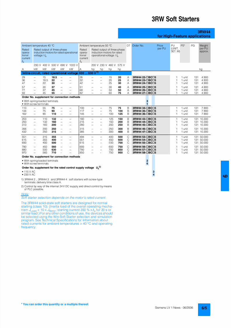
8122019 Arr Estado Solido
httpslidepdfcomreaderfullarr-estado-solido 940
3RW Soft Starters
3RW44for High-Feature applications
1) 3RW44 2 3RW44 3 and 3RW44 4 soft starters with screw-typeterminals delivery time class A
2) Control by way of the internal 24 V DC supply and direct control by meansof PLC possible
NoteSoft starter selection depends on the motors rated current
The 3RW44 solid-state soft starters are designed for normalstarting (class 10) (Inertia load of the overall operating mecha-nism J Load lt 10 x J Motor starting current 350 x I e for 20 s orsimilar load) For any other conditions of use the devices shouldbe selected using the Win-Soft Starter selection and simulationprogram See Technical Specifications for information aboutrated currents for ambient temperatures gt 40 degC and operating
frequency
Ambient temperature 40 degC Ambient temperature 50 degC DT Order No Priceper PU
PU(UNITSET M)
PS PG Weightper PUapprox
Ratedopera-
tionalcurrent I e
Rated output of three-phaseinduction motors for rated operational
voltage U e
Ratedopera-
tionalcurrent I e
Rated output of three-phaseinduction motors for rated
operational voltage U e
230 V 400 V 500 V 690 V 1000 V 200 V 230 V 460 V 575 V
A kW kW kW kW kW A hp hp hp hp kg
Inline circuit rated operational voltage 400 600 V1)
29 -- 15 185 -- -- 26 -- -- 15 20 A 3RW44 22-BC5 1 1 unit 131 490036 -- 185 22 -- -- 32 -- -- 20 25 A 3RW44 23-BC5 1 1 unit 131 490047 -- 22 30 -- -- 42 -- -- 25 30 A 3RW44 24-BC5 1 1 unit 131 4900
57 -- 30 37 -- -- 51 -- -- 30 40 A 3RW44 25-BC5 1 1 unit 131 490077 -- 37 45 -- -- 68 -- -- 50 50 A 3RW44 26-BC5 1 1 unit 131 490093 -- 45 55 -- -- 82 -- -- 60 75 A 3RW44 27-BC5 1 1 unit 131 4900
Order No supplement for connection methods
bull With spring-loaded terminals 3bull With screw terminals 1
113 -- 55 75 -- -- 100 -- -- 75 75 B 3RW44 34-BC5 1 1 unit 131 7900134 -- 75 90 -- -- 117 -- -- 75 100 B 3RW44 35-BC5 1 1 unit 131 7900
162 -- 90 110 -- -- 145 -- -- 100 125 B 3RW44 36-BC5 1 1 unit 131 7900
203 -- 110 132 -- -- 180 -- -- 125 150 B 3RW44 43-BC5 1 1 unit 131 10300250 -- 132 160 -- -- 215 -- -- 150 200 B 3RW44 44-BC5 1 1 unit 131 10300313 -- 160 200 -- -- 280 -- -- 200 250 B 3RW44 45-BC5 1 1 unit 131 10300
356 -- 200 250 -- -- 315 -- -- 250 300 B 3RW44 46-BC5 1 1 unit 131 10300432 -- 250 315 -- -- 385 -- -- 300 400 B 3RW44 47-BC5 1 1 unit 131 10300
551 -- 315 355 -- -- 494 -- -- 400 500 C 3RW44 53-BC5 1 1 unit 131 50000615 -- 355 400 -- -- 551 -- -- 450 600 C 3RW44 54-BC5 1 1 unit 131 50000693 -- 400 500 -- -- 615 -- -- 500 700 C 3RW44 55-BC5 1 1 unit 131 50000
780 -- 450 560 -- -- 693 -- -- 600 750 C 3RW44 56-BC5 1 1 unit 131 50000880 -- 500 630 -- -- 780 -- -- 700 850 C 3RW44 57-BC5 1 1 unit 131 50000970 -- 560 710 -- -- 850 -- -- 750 950 C 3RW44 58-BC5 1 1 unit 131 50000
Order No supplement for connection methods
bull With spring-loaded terminals 2bull With screw terminals 6
Order No supplement for the rated control supply voltage U s2)
bull 115 V AC 3bull 230 V AC 4
You can order this quantity or a multiple thereof
8122019 Arr Estado Solido
httpslidepdfcomreaderfullarr-estado-solido 1040
3RW Soft Starters
3RW44for High-Feature applications
1) Control by way of the internal 24 V DC supply and direct control by meansof PLC possible
NoteSoft starter selection depends on the motors rated current
The 3RW44 solid-state soft starters are designed for normalstarting (class 10) (Inertia load of the overall operating mecha- nism J Load lt 10 x J Motor starting current 350 x I e for 20 s orsimilar load) For any other conditions of use the devices shouldbe selected using the Win-Soft Starter selection and simulationprogram See Technical Specifications for information aboutrated currents for ambient temperatures gt 40 degC and operatingfrequency
Ambient temperature 40 degC Ambient temperature 50 degC DT Order No Priceper PU
PU(UNITSET M)
PS PG Weightper PUapprox
Ratedopera-
tionalcurrent I e
Rated output of three-phaseinduction motors for rated operational
voltage U e
Ratedopera-
tionalcurrent I e
Rated output of three-phaseinduction motors for rated
operational voltage U e
230 V 400 V 500 V 690 V 1000 V 200 V 230 V 460 V 575 V
A kW kW kW kW kW A hp hp hp hp kg
Inline circuit rated operational voltage 400 690 V
29 -- 15 185 30 -- 26 -- -- 15 20 B 3RW44 22-BC6 1 1 unit 131 490036 -- 185 22 37 -- 32 -- -- 20 25 B 3RW44 23-BC6 1 1 unit 131 490047 -- 22 30 45 -- 42 -- -- 25 30 B 3RW44 24-BC6 1 1 unit 131 4900
57 -- 30 37 55 -- 51 -- -- 30 40 B 3RW44 25-BC6 1 1 unit 131 490077 -- 37 45 75 -- 68 -- -- 50 50 B 3RW44 26-BC6 1 1 unit 131 490093 -- 45 55 90 -- 82 -- -- 60 75 B 3RW44 27-BC6 1 1 unit 131 4900
Order No supplement for connection methods
bull With spring-loaded terminals 3bull With screw terminals 1
113 -- 55 75 110 -- 100 -- -- 75 75 B 3RW44 34-BC6 1 1 unit 131 7900134 -- 75 90 132 -- 117 -- -- 75 100 B 3RW44 35-BC6 1 1 unit 131 7900
162 -- 90 110 160 -- 145 -- -- 100 125 B 3RW44 36-BC6 1 1 unit 131 7900
203 -- 110 132 200 -- 180 -- -- 125 150 B 3RW44 43-BC6 1 1 unit 131 10300250 -- 132 160 250 -- 215 -- -- 150 200 B 3RW44 44-BC6 1 1 unit 131 10300313 -- 160 200 315 -- 280 -- -- 200 250 B 3RW44 45-BC6 1 1 unit 131 10300
356 -- 200 250 355 -- 315 -- -- 250 300 B 3RW44 46-BC6 1 1 unit 131 10300432 -- 250 315 400 -- 385 -- -- 300 400 B 3RW44 47-BC6 1 1 unit 131 10300
551 -- 315 355 560 -- 494 -- -- 400 500 C 3RW44 53-BC6 1 1 unit 131 50000615 -- 355 400 630 -- 551 -- -- 450 600 C 3RW44 54-BC6 1 1 unit 131 50000693 -- 400 500 710 -- 615 -- -- 500 700 C 3RW44 55-BC6 1 1 unit 131 50000
780 -- 450 560 800 -- 693 -- -- 600 750 C 3RW44 56-BC6 1 1 unit 131 50000880 -- 500 630 900 -- 780 -- -- 700 850 C 3RW44 57-BC6 1 1 unit 131 50000970 -- 560 710 1000 -- 850 -- -- 750 950 C 3RW44 58-BC6 1 1 unit 131 50000
Order No supplement for connection methods
bull With spring-loaded terminals 2bull With screw terminals 6
Order No supplement for the rated control supply voltage U s1)
bull 115 V AC 3bull 230 V AC 4
8122019 Arr Estado Solido
httpslidepdfcomreaderfullarr-estado-solido 1140
3RW Soft Starters
3RW44for High-Feature applications
1) In the selection table the unit rated operational current I e refers to the
three-phase motors rated operational current in the inside-delta circuitThe actual current of the unit is approx 58 of this value
2) 3RW44 2 3RW44 3 and 3RW44 4 soft starters with screw-typeterminals delivery time class (preferred type)
3) Control by way of the internal 24 V DC supply and direct control by meansof PLC possible
NoteSoft starter selection depends on the motors rated current
The 3RW44 solid-state soft starters are designed for normalstarting (class 10) (Inertia load of the overall operatingmechanism JLoad lt 10 x JMotor starting current 350 x Ie for20 s or similar load) For any other conditions of use the devicesshould be selected using the Win-Soft Starter selection andsimulation program See Technical Specifications for informationabout rated currents for ambient temperatures gt 40 degC andoperating frequency
3RW44 27-1BC44 3RW44 36-6BC44 3RW44 47-6BC44 3RW44 58-6BC44
Ambient temperature 40 degC Ambient temperature 50 degC DT Order No Priceper PU
PU(UNITSET M)
PS PG Weightper PUapprox
Ratedopera-tionalcurrent I e
1)
Rated output of three-phase inductionmotors for rated operational voltageU e
Ratedopera-tionalcurrent I e
Rated output of three-phaseinduction motors for ratedoperational voltage U e
230 V 400 V 500 V 690 V 1000 V 200 V 230 V 460 V 575 V
A kW kW kW kW kW A hp hp hp hp kgInside-delta circuits rated operational voltage 200 460 V2)
50 15 22 -- -- -- 45 10 15 30 -- B 3RW44 22-BC4 1 1 unit 131 490062 185 30 -- -- -- 55 15 20 40 -- B 3RW44 23-BC4 1 1 unit 131 490081 22 45 -- -- -- 73 20 25 50 -- B 3RW44 24-BC4 1 1 unit 131 4900
99 30 55 -- -- -- 88 25 30 60 -- B 3RW44 25-BC4 1 1 unit 131 4900133 37 75 -- -- -- 118 30 40 75 -- B 3RW44 26-BC4 1 1 unit 131 4900161 45 90 -- -- -- 142 40 50 100 -- B 3RW44 27-BC4 1 1 unit 131 4900
Order No supplement for connection methods
bull With spring-loaded terminals 3bull With screw terminals 1
196 55 110 -- -- -- 173 50 60 125 -- B 3RW44 34-BC4 1 1 unit 131 7900232 75 132 -- -- -- 203 60 75 150 -- B 3RW44 35-BC4 1 1 unit 131 7900281 90 160 -- -- -- 251 75 100 200 -- B 3RW44 36-BC4 1 1 unit 131 7900
352 110 200 -- -- -- 312 100 125 250 -- B 3RW44 43-BC4 1 1 unit 131 10300433 132 250 -- -- -- 372 125 150 300 -- B 3RW44 44-BC4 1 1 unit 131 10300542 160 315 -- -- -- 485 150 200 400 -- B 3RW44 45-BC4 1 1 unit 131 10300
617 200 355 -- -- -- 546 150 200 450 -- B 3RW44 46-BC4 1 1 unit 131 10300748 250 400 -- -- -- 667 200 250 600 -- B 3RW44 47-BC4 1 1 unit 131 10300
954 315 560 -- -- -- 856 300 350 750 -- C 3RW44 53-BC4 1 1 unit 131 500001065 355 630 -- -- -- 954 350 400 850 -- C 3RW44 54-BC4 1 1 unit 131 500001200 400 710 -- -- -- 1065 350 450 950 -- C 3RW44 55-BC4 1 1 unit 131 50000
1351 450 800 -- -- -- 1200 450 500 1050 -- C 3RW44 56-BC4 1 1 unit 131 500001524 500 900 -- -- -- 1351 450 600 1200 -- C 3RW44 57-BC4 1 1 unit 131 500001680 560 1000 -- -- -- 1472 550 650 1300 -- C 3RW44 58-BC4 1 1 unit 131 50000
Order No supplement for connection methods
bull With spring-loaded terminals 2bull With screw terminals 6
Order No supplement for the rated control supply voltage U s3)
bull 115 V AC 3bull 230 V AC 4
You can order this quantity or a multiple thereof
8122019 Arr Estado Solido
httpslidepdfcomreaderfullarr-estado-solido 1240
3RW Soft Starters
3RW44for High-Feature applications
1) In the selection table the unit rated operational current I e refers to thethree-phase motors rated operational current in the inside-delta circuitThe actual current of the unit is approx 58 of this value
2) 3RW44 2 3RW44 3 and 3RW44 4 soft starters with screw-typeterminals delivery time class A
3) Control by way of the internal 24 V DC supply and direct control by meansof PLC possible
Accessories
NoteSoft starter selection depends on the motors rated current
The 3RW44 solid-state soft starters are designed for normalstarting (class 10) (Inertia load of the overall operatingmechanism J Load lt 10 x J Motor starting current 350 x I e for20 s or similar load) For any other conditions of use the devicesshould be selected using the Win-Soft Starter selection andsimulation program See Technical Specifications for informationabout rated currents for ambient temperatures gt 40 degC andoperating frequency
Ambient temperature 40 degC Ambient temperature 50 degC DT Order No Priceper PU
PU(UNITSET M)
PS PG Weightper PUapprox
Ratedopera-
tionalcurrent I e
1)
Rated output of three-phaseinduction motors for rated opera-
tional voltage U e
Ratedopera-
tionalcurrent I e
Rated output of three-phaseinduction motors for rated
operational voltage U e
230 V 400 V 500 V 690 V 1000 V 200 V 230 V 460 V 575 V
A kW kW kW kW kW A hp hp hp hp kg
Inside-delta circuits rated operational voltage 400 600 V2)
50 -- 22 30 -- -- 45 -- -- 30 40 B 3RW44 22-BC5 1 1 unit 131 490062 -- 30 37 -- -- 55 -- -- 40 50 B 3RW44 23-BC5 1 1 unit 131 490081 -- 45 45 -- -- 73 -- -- 50 60 B 3RW44 24-BC5 1 1 unit 131 4900
99 -- 55 55 -- -- 88 -- -- 60 75 B 3RW44 25-BC5 1 1 unit 131 4900133 -- 75 90 -- -- 118 -- -- 75 100 B 3RW44 26-BC5 1 1 unit 131 4900161 -- 90 110 -- -- 142 -- -- 100 125 B 3RW44 27-BC5 1 1 unit 131 4900
Order No supplement for connection methods
bull With spring-loaded terminals 3bull With screw terminals 1
196 -- 110 132 -- -- 173 -- -- 125 150 B 3RW44 34-BC5 1 1 unit 131 7900232 -- 132 160 -- -- 203 -- -- 150 200 B 3RW44 35-BC5 1 1 unit 131 7900
281 -- 160 200 -- -- 251 -- -- 200 250 B 3RW44 36-BC5 1 1 unit 131 7900
352 -- 200 250 -- -- 312 -- -- 250 300 B 3RW44 43-BC5 1 1 unit 131 10300433 -- 250 315 -- -- 372 -- -- 300 350 B 3RW44 44-BC5 1 1 unit 131 10300542 -- 315 355 -- -- 485 -- -- 400 500 B 3RW44 45-BC5 1 1 unit 131 10300
617 -- 355 450 -- -- 546 -- -- 450 600 B 3RW44 46-BC5 1 1 unit 131 10300748 -- 400 500 -- -- 667 -- -- 600 750 B 3RW44 47-BC5 1 1 unit 131 10300
954 -- 560 630 -- -- 856 -- -- 750 950 C 3RW44 53-BC5 1 1 unit 131 500001065 -- 630 710 -- -- 954 -- -- 850 1050 C 3RW44 54-BC5 1 1 unit 131 500001200 -- 710 800 -- -- 1065 -- -- 950 1200 C 3RW44 55-BC5 1 1 unit 131 50000
1351 -- 800 900 -- -- 1200 -- -- 1050 1350 C 3RW44 56-BC5 1 1 unit 131 500001524 -- 900 1000 -- -- 1351 -- -- 1200 1500 C 3RW44 57-BC5 1 1 unit 131 500001680 -- 1000 1200 -- -- 1472 -- -- 1300 1650 C 3RW44 58-BC5 1 1 unit 131 50000
Order No supplement for connection methods
bull With spring-loaded terminals 2bull With screw terminals 6
Order No supplement for the rated control supply voltage U s3)
bull 115 V AC 3bull 230 V AC 4
Forsoft starters Version DT Order No Priceper PU PU(UNITSET M)
PS PG Weightper PUapprox
Type kg
Soft Starter ES 2006 PC communication program
Soft Starter ES 2006 Smart
Parameterization and service software forSIRIUS 3RW44 soft starters for parameterizingthrough the system interface on the deviceExecutes on PCPG under Windows 2000XPwithout PC cableType of supply CD single license
3ZS1 313-1CC10-0YA0 1 1 unit 131 0230
3ZS1 313-1CC10-0YA0 Soft Starter ES 2006 Professional
Parameterization and service software forSIRIUS 3RW44 soft starters for parameterizingthrough the system interface on the device andPROFIBUS DP interface (PROFIBUS as optional commu-nication module necessary)Executes on PCPG under Windows 2000XPwithout PC cableType of supply CD single license
A 3ZS1 313-2CC10-0YA0 1 1 unit 131 0230
8122019 Arr Estado Solido
httpslidepdfcomreaderfullarr-estado-solido 1340
3RW Soft Starters
3RW44for High-Feature applications
Spare parts
Forsoft starters
Version DT Order No Priceper PU
PU(UNITSET M)
PS PG Weightper PUapprox
Type kg
PC cables
For PCPG communication with SIRIUS 3RW44soft starters
through the system interface for connecting tothe serial interface of the PCPG
B 3UF7 940-0AA00-0 1 1 unit 131 0150
Box terminal blocks for soft starters
Box terminal blocks
3RW44 2 Included in del ivery
3RW44 3 bull Up to 70 mm2 3RT19 55-4G 1 1 unit 101 0237
bull Up to 120 mm2 3RT19 56-4G 1 1 unit 101 0270
3RW44 3 bull Up to 240 mm2 3RT19 66-4G 1 1 unit 101 0676
PROFIBUS Communication moduleModule to be plugged into the soft starter to connect thesoft starter to the PROFIBUS net
A 3RW4 900-0KC00 1 1 unit 131 0320
External display and operation module
to show and operate the fonctions supplied by the softstarter via externally mounted display and operationmodule(for example in the cubicle door)
A 3RW4 900-0AC00 1 1 unit 131 0320
Connection cable
from serial interface of 3RW44 soft starter to external dis-play and operation modulebull Length 05 m flat B 3UF7 932-0AA00-0 1 1 unit 131 0020bull Length 05 m round A 3UF7 932-0BA00-0 1 1 unit 131 0050bull Length10 m round A 3UF7 937-0BA00-0 1 1 unit 131 0100bull Length25 m round A 3UF7 933-0BA00-0 1 1 unit 131 0150
Covers for soft starters
Terminal covers for box terminals
Additional touch protection to be fitted at the boxterminals (2 units required per device)
3RW44 2 and3RW44 3
3RT19 56-4EA2 1 1 unit 101 0028
3RW44 4 3RT19 66-4EA2 1 1 unit 101 0038
Terminal covers for cable lugs and busbarconnections
3RW44 2 and3RW44 3
3RT19 56-4EA1 1 1 unit 101 0067
3RW44 4 3RT19 66-4EA1 1 1 unit 101 0124
Forsoft starters
Version DT Order No Priceper PU
PU(UNITSET M)
PS PG Weightper PUapprox
Type kg
Fans
Fans
3RW44 2 and3RW44 3
115 VAC 3RW49 36-8VX30 1 1 unit 131 0300230 VAC 3RW49 36-8VX40 1 1 unit 131 0300
3RW44 4 115 V AC 3RW49 47-8VX30 1 1 unit 131 0500230 VAC 3RW49 47-8VX40 1 1 unit 131 0500
3RW44 5 115 V AC 3RW49 57-8VX30 1 1 unit 131 0800230 VAC 3RW49 57-8VX40 1 1 unit 131 0800
You can order this quantity or a multiple thereof
8122019 Arr Estado Solido
httpslidepdfcomreaderfullarr-estado-solido 1440
3RW Soft Starters
3RW44for High-Feature applications
Function
Equipped with modern ergonomic user prompting theSIRIUS 3RW44 soft starters can be commissioned quickly and
easily using a keypad and a menu-prompted multi-line displaywith background lighting Motor starting and deceleration areoptimized quickly easily and safely with just a few settings in aselectable language Four-key operation and plain-text displaysfor each menu point guarantee full clarity at every moment of theparameterization and operation Measurement values and oper-ating values as well as warning messages and fault indicationsare output continuously on the front panel during operation andwhen control voltage is applied An external display and opera-tor module can be connected by means of a connecting cableto the soft starter thus enabling active indications and the like tobe read directly from the control cabinet door
The SIRIUS 3RW44 soft starters are equipped with optimumfunctionality An integral bypass contact system reduces thepower loss of the soft starter during operation This reliablyprevents heating of the switchgear environment TheSIRIUS 3RW44 soft starters have internal intrinsic deviceprotection This prevents thermal overloading of the powersections thyristors eg due to unacceptably high closingoperations
Wiring work for installing an additional motor overload relay is nolonger needed as the SIRIUS 3RW44 soft starters perform thisfunction too In addition they offer adjustable trip classes and athermistor motor protection function As an option the thyristorscan also be protected by SITOR semi-conductor fuses fromshort-circuiting And even inrush current peaks are reliablyavoided thanks to adjustable current limiting
As a further option the SIRIUS 3RW44 soft starters can beupgraded with a PROFIBUS DP module Thanks to their commu-nication capability and their programmable control inputs andrelay outputs the SIRIUS 3RW44 soft starters can be very easily
and quickly integrated in higher-level controllersIn addition a creep speed function is available for positioningand setting jobs With this function the motor can be controlledin both directions of rotation with reduced torque and an adjust-able low speed
On the other hand the SIRIUS 3RW44 soft starters offer a newcombined DC braking function for the fast stopping of drivingloads
Highlights bull Soft starting with breakaway pulse torque control or voltage
ramp and adjustable torque or current limiting as well as anycombination of these depending on load type
bull Integrated bypass contact system to minimize dissipatedpower
bull Various setting options for the starting parameters such asstarting torque starting voltage ramp-up and ramp-downtime and much more in three separate parameter sets
bull Start-up detectionbull Inside-delta circuit for savings in terms of size and equipment
costsbull Various ramp-down modes selectable free ramp-down
torque-controlled pump stopping combined DC brakingbull Solid-state motor overload and intrinsic device protectionbull Thermistor motor protectionbull Keypad with a menu-controlled multi-line graphic display with
background lighting
bull Interface for communication with the PC for more accuratesetting of the parameters as well as for control and monitoringbull Simple adaptation to the motor feederbull Simple mounting and commissioningbull Display of operating states and fault signalsbull Connection to PROFIBUS with optional PROFIBUS DP modulebull External display and operator modulebull System voltages from 200 to 690 V 50 to 60 Hzbull Applicable up to 60 degC (derating from 40 degC)
8122019 Arr Estado Solido
httpslidepdfcomreaderfullarr-estado-solido 1540
3RW Soft Starters
3RW44for High-Feature applications
Technical specifications
Type 3RW44 -BC3 3RW44 -BC4Terminal
Control electronics
Rated valuesRated control supply voltage A1A2PE V 115 AC 230 ACbull Tolerance -15+10 -15+10Rated control supply current STANDBY mA 30 20
Rated control supply current ONbull 3RW44 2 mA 300 170bull 3RW44 3 mA 500 250bull 3RW44 4 mA 750 400bull 3RW44 5 mA 450 200
Maximum current (pickup bypass)bull 3RW44 2 mA 1000 500bull 3RW44 3 mA 2500 1250bull 3RW44 4 mA 6000 3000bull 3RW44 5 mA 4500 2500
Rated frequency Hz 50 60 50 60bull Tolerance plusmn10 plusmn10
Type 3RW44 Terminal Factory presetting
Control electronics
Control inputsInput 1 IN1 Start motor right parameter set 1Input 2 IN2 No actionInput 3 IN3 No actionInput 4 IN4 Trip reset
Supply L+L-bull Rated operational current mA Approx 10 per input to DIN 19240bull Rated operational voltage L+ Internal voltage 24 V DC from inter-
nal supply through terminal L+ toIN1 IN4 Maximum load at L+approx 55 mA
L- External voltage DC external voltage(to DIN19240) through terminals
L- and IN1 IN4(min 12 V DC max 30 V DC)
Thermistor motor protection inputInput T1T2 PTC type A or Thermoclick Deactivated
Relay outputs (floating auxiliary contacts)Output 1 1314 ON periodOutput 2 2324 No actionOutput 3 3334 No actionOutput 4 959698 Group fault
Switching capacity of the relay outputs230 VAC-15 A 3 at 240 V24 VDC-13 A 1 at 24 VProtection against overvoltages Protection by means of Varistor through relay contactShort-circuit protection 4 A gLgG operational class
6 A quick (fuse is not included in scope of supply)
Protective functions
Motor protection functionsTrips in the event of Thermal overloading of the motor
Trip class to IEC 60947-4-1 Class 510152030 10Phase failure sensitivity gt 40
Overload warning yesReset and recovery ManualAutomatic ManualReset option after tripping ManualAutomatic ManualRecovery time min 1 30 1
Device protection functionsTrips in the event of Thermal overloading of the thyristorsReset option after tripping ManualAutomatic ManualRecovery time min 05
8122019 Arr Estado Solido
httpslidepdfcomreaderfullarr-estado-solido 1640
3RW Soft Starters
3RW44for High-Feature applications
Type 3RW44 Factory presetting
Control times and parameters
Control timesClosing delay (with connected control voltage) ms lt 50Closing delay (automatic mode) ms lt 4000Recovery time (closing command in active ramp-down) ms lt 100
Mains failure bridging timeControl supply voltage ms 100
Mains failure response timeLoad current circuit ms 100
Reclosing lockout after overload tripMotor protection trip min 1 30 1Device protection trip s 30
Setting options for startingVoltage ramp for starting voltage 20 100 30Torque control for starting torque 20 100 50Torque control for limit torque 20 200 150
Starting time s 0 360 20Maximum starting time s 1 1000 DeactivatedCurrent limit value 125 550 450
Breakaway voltage 40 100 80Breakaway time s 0 2 DeactivatedMotor heat output 0 100 0
Creep mode LeftRight runningSpeed factor as function of rated speed (n = n rated factor) 3 21 7Creep torque (reference variable depends on the motor used but isalways smaller than the rated torque of the motor)
20 100 50
Setting options for ramp-downTorque control for stopping torque 10 100 10Ramp-down time s 0 360 10Dynamic braking torque 20 100 50DC braking torque 20 100 50
Operating indicationsTest voltageTest mains phasesReady to start
Start active
Motor runningRamp-down active
Warningserror signalsMains voltage missingLeading-edge phase error
Phase failurebull L1bull L2bull L3
Missing load phasebull T1bull T2bull T3
Failurebull Contact element 1 (thyristor)bull Contact element 2 (thyristor)bull Contact element 3 (thyristor)
Flash memory faulty
Supply voltagebull Below 75 bull Below 85 bull Over 110
Current unbalance exceededThermal motor model overload
Prewarning limit exceededbull Motor heatingbull Time-related trip reserve
Bypass elements defectiveMains voltage too high
Device not namedWrong naming versionCurrent range exceeded
Motor blocking ndash shutdownCurrent limit exceeded
Power section
bull Overheatedbull OvertemperatureEmergency active
8122019 Arr Estado Solido
httpslidepdfcomreaderfullarr-estado-solido 1740
3RW Soft Starters
3RW44for High-Feature applications
1) Parameter motor left possible only in conjunction with creep mode
Type 3RW44 Factory presetting
Control times and parameters
Warningserror signals (contd)Temperature sensorbull Overloadbull Open-circuitbull Short-circuit
Ground faultbull Detectedbull Shutdown
Connection abort in manual modeMax number of starts exceeded I e limit value overshootundershoot
Cooling timebull Motor activebull Switch block active
Heat sink sensorbull Open-circuitbull Short-circuit
Quick-stop functionSwitch block faulty I e class setting not permissible
Control inputsInput 1 Motor right parameter set 1Input 2 No actionInput 3 No actionInput 4 Trip reset
Parameterizing options for control inputs 1 4 No actionLocal manual modeEmergency startCreep speedQuick-stopTrip reset
Motor right parameter set 1Motor left parameter set 11) Motor right parameter set 2Motor left parameter set 21) Motor right parameter set 3Motor left parameter set 31)
Relay outputsOutput 1 ON periodOutput 2 No actionOutput 3 No actionOutput 4 Group fault
Parameterizing options for relay outputs 1 3 No actionPAA output 1PAA output 2
Input 1Input 2Input 3Input 4
Ramp-upOperationBypassRamp-downON periodCommand motor on
FanDC braking contactor
Group warningGroup faultBus faultDevice error
Power onReady to start
Motor temperature sensors Deactivated DeactivatedThermoclickPTC type A
8122019 Arr Estado Solido
httpslidepdfcomreaderfullarr-estado-solido 1840
3RW Soft Starters
3RW44for High-Feature applications
1) Current limit on soft starter set to 350 I M
2) For intermittent duty S4 with ON period = 70 T u = 40 degC stand-aloneinstallation vertical The quoted operating frequencies do not apply forautomatic mode
3) Maximum adjustable rated motor current I M dependent on CLASS setting
Type 3RW44 -BC4 3RW44 -BC5 3RW44 -BC6
Power electronics
Rated operational voltage for inline circuit V 200 460 AC 400 600 AC 400 690 AC
Tolerance -15+10 -15+10 -15+10Rated operational voltage for inside-delta circuit V 200 460 AC 400 600 AC 400 600 ACTolerance -15+10 -15+10 -15+10
Rated frequency Hz 50 60Tolerance plusmn10
Continuous operation at 40 degC ( of I e) 115
Minimum load ( of set motor current I M) 8
Maximum conductor length between soft starter and motor m 200
Permissible installation height m 5000 (derating from 1000 see characteristics) higher on request
Permissible mounting position
Permissible ambient temperatureOperation degC 0 +60 (derating from +40)Storage degC -25 +80
Degree of protection IP00
Type 3RW44 22 3RW44 23 3RW44 24 3RW44 25 3RW44 26 3RW44 27
Power electronics
Rated operational current I e 29 36 47 57 77 93
Load rating with rated operational current I ebull Acc to IEC and ULCSA for individual mounting
at 405060 degC AC-53a A 292623 363229 474237 575145 776859 938272
Smallest adjustable rated motor current I Mfor the motor overload protection
A 5 7 9 11 15 18
Power lossbull In operation after completed ramp-up with uninterrupted rated
operational current (40 degC) approx W 8 10 32 36 45 55bull During starting with current limit set to 350 I M (40 degC) W 400 470 600 725 940 1160
Permissible rated motor current and starts per hour
bull Normal starting (Class 5)- Rated motor current I M
1) starting time 5 s A 29 36 47 57 77 93- Starts per hour2) 1h 41 34 41 41 41 41
- Rated motor current I M1)3) starting time 10 s A 29 36 47 57 77 93
- Starts per hour2) 1h 20 15 20 20 20 20
bull Normal starting (Class 10)- Rated motor current I M
1) starting time 10 s A 29 36 47 57 77 93- Starts per hour2) 1h 20 15 20 20 20 20
- Rated motor current I M1)3) starting time 20 s A 29 36 47 57 77 93
- Starts per hour2) 1h 10 6 10 10 8 8
bull Normal starting (Class 15)- Rated motor current I M
1) starting time 15 s A 29 36 47 57 77 93- Starts per hour2) 1h 13 9 13 13 13 13
- Rated motor current I M1)3) starting time 30 s A 29 36 47 57 77 93
- Starts per hour2) 1h 6 4 6 6 6 6
bull For heavy starting (Class 20)- Rated motor current I M
1) starting time 20 s A 29 36 47 57 73 88- Starts per hour2) 1h 10 6 10 10 10 10
- Rated motor current I M1)3) starting time 40 s A 29 36 47 57 73 88
- Starts per hour2) 1h 4 2 4 5 18 08
bull For very heavy starting (Class 30)- Rated motor current I M
1) starting time 30 s A 29 36 44 57 65 77- Starts per hour2) 1h 6 4 6 6 6 6
- Rated motor current I M1)3) starting time 60 s A 29 36 44 57 65 77
- Starts per hour2) 1h 18 08 33 15 2 1
8122019 Arr Estado Solido
httpslidepdfcomreaderfullarr-estado-solido 1940
3RW Soft Starters
3RW44for High-Feature applications
1) Current limit on soft starter set to 350 I M
2) For intermittent duty S4 with ON period = 70 T u = 40 degC stand-aloneinstallation vertical The quoted operating frequencies do not apply forautomatic mode
3) Maximum adjustable rated motor current I M dependent on CLASS setting
Type 3RW44 34 3RW44 35 3RW44 36
Power electronics
Rated operational current I e 113 134 162
Load rating with rated operational current I ebull Acc to IEC and ULCSA for individual mounting AC-53a
- at 40 degC A 113 134 162- at 50 degC A 100 117 145- at 60 degC A 88 100 125
Smallest adjustable rated motor current I Mfor the motor overload protection
A 22 26 32
Power lossbull In operation after completed ramp-up with uninterrupted rated
operational current (40 degC) approx W 64 76 95bull During starting with current limit set to 350 I M (40 degC) W 1350 1700 2460
Permissible rated motor current and starts per hour
bull Normal starting (Class 5)- Rated motor current I M
1) starting time 5 s A 113 134 162- Starts per hour2) 1h 41 39 41
- Rated motor current I M1)3) starting time 10 s A 113 134 162
- Starts per hour2) 1h 20 15 20
bull Normal starting (Class 10)- Rated motor current I M
1) starting time 10 s A 113 134 162- Starts per hour2) 1h 20 15 20
- Rated motor current I M1)3) starting time 20 s A 113 134 162
- Starts per hour2) 1h 9 6 7
bull Normal starting (Class 15)- Rated motor current I M
1) starting time 15 s A 113 134 162- Starts per hour2) 1h 13 9 12
- Rated motor current I M1)3) starting time 30 s A 113 134 162
- Starts per hour2) 1h 6 6 1
bull For heavy starting (Class 20)- Rated motor current I M
1) starting time 20 s A 106 125 147- Starts per hour2) 1h 9 9 10
- Rated motor current I M1)3) starting time 40 s A 106 125 147
- Starts per hour2) 1h 15 2 1
bull For very heavy starting (Class 30)- Rated motor current I M
1) starting time 30 s A 91 110 120
- Starts per hour2) 1h 6 6 6- Rated motor current I M
1)3) starting time 60 s A 91 110 120- Starts per hour2) 1h 2 2 2
8122019 Arr Estado Solido
httpslidepdfcomreaderfullarr-estado-solido 2040
3RW Soft Starters
3RW44for High-Feature applications
1) Current limit on soft starter set to 350 I M
2) For intermittent duty S4 with ON period = 70 T u = 40 degC stand-aloneinstallation vertical The quoted operating frequencies do not apply forautomatic mode
3) Maximum adjustable rated motor current I M dependent on CLASS setting
Type 3RW44 43 3RW44 44 3RW44 45 3RW44 46 3RW44 47
Power electronics
Rated operational current I e 203 250 313 356 432
Load rating with rated operational current I ebull Acc to IEC and ULCSA for individual mounting AC-53a
- at 40 degC A 203 250 313 356 432- at 50 degC A 180 215 280 315 385- at 60 degC A 156 185 250 280 335
Smallest adjustable rated motor current I Mfor the motor overload protection
A 40 50 62 71 86
Power lossbull In operation after completed ramp-up with uninterrupted rated
operational current (40 degC) approx W 89 110 145 174 232bull During starting with current limit set to 350 I M (40 degC) W 3350 4000 4470 5350 5860
Permissible rated motor current and starts per hour
bull Normal starting (Class 5)- Rated motor current I M
1) starting time 5 s A 203 250 313 356 432- Starts per hour2) 1h 41 41 41 41 39
- Rated motor current I M1)3) starting time 10 s A 203 250 313 356 432
- Starts per hour2) 1h 20 20 19 17 16
bull Normal starting (Class 10)- Rated motor current I M
1) starting time 10 s A 203 250 313 356 432- Starts per hour2) 1h 20 20 19 17 16
- Rated motor current I M1)3) starting time 20 s A 203 250 313 356 432
- Starts per hour2) 1h 9 10 6 4 5
bull Normal starting (Class 15)- Rated motor current I M
1) starting time 15 s A 203 240 313 325 402- Starts per hour2) 1h 13 13 10 13 11
- Rated motor current I M1)3) starting time 30 s A 203 240 313 325 402
- Starts per hour2) 1h 3 6 1 2 1
bull For heavy starting (Class 20)- Rated motor current I M
1) starting time 20 s A 195 215 275 285 356- Starts per hour2) 1h 10 10 10 10 10
- Rated motor current I M1)3) starting time 40 s A 195 215 275 285 356
- Starts per hour2) 1h 1 5 1 3 1
bull For very heavy starting (Class 30)- Rated motor current I M
1) starting time 30 s A 162 180 220 240 285
- Starts per hour2) 1h 6 6 6 6 6- Rated motor current I M
1)3) starting time 60 s A 162 180 220 240 285- Starts per hour2) 1h 3 3 3 2 1
8122019 Arr Estado Solido
httpslidepdfcomreaderfullarr-estado-solido 2140
3RW Soft Starters
3RW44for High-Feature applications
1) Current limit on soft starter set to 350 I M
2) For intermittent duty S4 with ON period = 70 T u = 40 degC stand-aloneinstallation vertical The quoted operating frequencies do not apply forautomatic mode
3) Maximum adjustable rated motor current I M dependent on CLASS setting
Type 3RW44 53 3RW44 54 3RW44 55 3RW44 56 3RW44 57 3RW44 58
Power electronics
Rated operational current I e 551 615 693 780 880 970
Load rating with rated operational current I ebull Acc to IEC and ULCSA for individual mounting AC-53a
- at 40 degC A 551 615 693 780 880 970- at 50 degC A 494 551 615 693 780 850- at 60 degC A 438 489 551 615 693 760
Smallest adjustable rated motor current I Mfor the motor overload protection
A 110 123 138 156 176 194
Power lossbull In operation after completed ramp-up with uninterrupted rated
operational current (40 degC) approx W 159 186 220 214 250 270bull During starting with current limit set to 350 I M (40 degC) W 7020 8100 9500 11100 13100 15000
Permissible rated motor current and starts per hour
bull Normal starting (Class 5)- Rated motor current I M
1) starting time 5 s A 551 615 693 780 880 970- Starts per hour2) 1h 41 41 37 33 22 17
- Rated motor current I M1)3) starting time 10 s A 551 615 693 780 880 970
- Starts per hour2) 1h 20 20 16 13 8 5
bull Normal starting (Class 10)- Rated motor current I M
1) starting time 10 s A 551 615 693 780 880 970- Starts per hour2) 1h 20 20 16 13 8 5
- Rated motor current I M1)3) starting time 20 s A 551 615 693 780 880 970
- Starts per hour2) 1h 10 9 6 4 03 03
bull Normal starting (Class 15)- Rated motor current I M
1) starting time 15 s A 551 615 666 723 780 821- Starts per hour2) 1h 13 13 11 9 8 8
- Rated motor current I M1)3) starting time 30 s A 551 615 666 723 780 821
- Starts per hour2) 1h 6 4 3 1 04 05
bull For heavy starting (Class 20)- Rated motor current I M
1) starting time 20 s A 551 591 633 670 710 740- Starts per hour2) 1h 10 10 7 8 8 9
- Rated motor current I M1)3) starting time 40 s A 551 591 633 670 710 740
- Starts per hour2) 1h 4 2 1 1 04 1
bull For very heavy starting (Class 30)- Rated motor current I M
1) starting time 30 s A 500 525 551 575 600 630
- Starts per hour2) 1h 6 6 6 6 6 6- Rated motor current I M
1)3) starting time 60 s A 500 525 551 575 600 630- Starts per hour2) 1h 2 1 1 1 15 1
8122019 Arr Estado Solido
httpslidepdfcomreaderfullarr-estado-solido 2240
3RW Soft Starters
3RW44for High-Feature applications
1) When connecting cable lugs to DIN 46235 use 3RT19 56-4EA1 terminalcover for conductor cross-sections from 95 mmsup2 to ensure phase spacing
2) When connecting cable lugs to DIN 46234 the 3RT19 66-4EA1 terminalcover must be used for conductor cross-sections of 240 mmsup2 and more aswell as DIN 46235 for conductor cross-sections of 185 mmsup2 and more tokeep the phase clearance
Type 3RW44 2 3RW44 3 3RW44 4 3RW44 5
Conductor cross-sections
Screw
terminals
Main conductors
with box terminal 3RT19 55-4G (55 kW) 3RT19 66-4G
Front clampingpoint connected
bull Finely stranded with end sleeve mm2 16 70 70 240bull Finely stranded without end sleeve mm2 16 70 70 240bull Stranded mm2 16 70 95 300
bull Ribbon cable conductors(number x width x thickness)
mm min 3 x 9 x 08max 6 x 155 x 08
min 6 x 9 x 08max 20 x 24 x 05
bull AWG conductors solid or stranded AWG 6 20 30 600 kcmil
Rear clamping pointconnected
bull Finely stranded with end sleeve mm2 16 70 120 185bull Finely stranded without end sleeve mm2 16 70 120 185bull Stranded mm2 16 70 120 240
bull Ribbon cable conductors(number x width x thickness)
mm min 3 x 9 x 08max 6 x 155 x 08
min 6 x 9 x 08max 20 x 24 x 05
bull AWG conductors solid or stranded AWG 6 20 250 500 kcmil
Both clamping
points connected
bull Finely stranded with end sleeve mm2 max 1 x 50 1 x 70 min 2 x 50 max 2 x 185
bull Finely stranded without end sleeve mm2 max 1 x 50 1 x 70 min 2 x 50 max 2 x 185bull Stranded mm2 max 2 x 70 max 2 x 70 max 2 x 240
bull Ribbon cable conductors(number x width x thickness)
mm max 2 x (6 x 155 x 08) max 2 x (20 x 24 x 05)
bull AWG conductors solid or stranded AWG max 2 x 10 min 2 x 20max 2 x 500 kcmil
bull Terminal screws M10 (hexagon socket AF4) M12 (hexagon socket AF5)- Pickup torque 10 12 20 22
90 110 180 195
Screwterminals
Main conductors
with box terminal 3RT19 56-4G
Front or rear clamp-ing point connected
bull Finely stranded with end sleeve mm2 16 120bull Finely stranded without end sleeve mm2 16 120bull Stranded mm2 16 120
bull Ribbon cable conductors(number x width x thickness)
mm min 3 x 9 x 08max 6 x 155 x 08
bull AWG conductors solid or stranded AWG 6 250 kcmil
Both clampingpoints connected
bull Finely stranded with end sleeve mm2 max 1 x 95 1 x 120bull Finely stranded without end sleeve mm2 max 1 x 95 1 x 120bull Stranded mm2 max 2 x 120
bull Ribbon cable conductors(number x width x thickness)
mm max 2 x (10 x 155 x 08)
bull AWG conductors solid or stranded AWG max 2 x 30
Screwterminals
Main conductors
Without box terminalrail connection
bull Finely stranded with cable lug mm2 16 951) 50 2402) 50 2402)
bull Stranded with cable lug mm2 25 1201) 70 2402) 70 2402)
bull AWG conductors solid or stranded AWG 4 250 kcmil 20 500 kcmil 10 500 kcmil
bull Connecting bar (max width) mm 17 25 60
bull Terminal screws M8 x 25 (AF13) M10 x 30 (AF17) M12 x 40- Pickup torque NM 10 14 14 24 20 35lbin 89 124 124 210 177 310
8122019 Arr Estado Solido
httpslidepdfcomreaderfullarr-estado-solido 2340
3RW Soft Starters
3RW44for High-Feature applications
Soft starters Type 3RW44
Conductor cross-sections
Auxiliary conductors (1 or 2 conductors can be connected)
Screw terminals
bull Solid mm2 2 x 05 25bull Finely stranded with end sleeve mm2 2 x 05 15
bull AWG cables- Solid or stranded AWG 2 x 20 14- Finely stranded with end sleeve AWG 2 x 20 16
bull Terminal screws- Pickup torque NM 07 09
lbin 7 8
Spring-loaded terminals
bull Solid mm2 2 x 025 25bull Finely stranded with end sleeve mm2 2 x 025 15bull AWG conductors solid or stranded AWG 2 x 24 14
Standard Parameters
Electromagnetic compatibility acc to EN 60947-4-2
EMC interference immunityElectrostatic discharge (ESD) EN 61000-4-2 plusmn4 kV contact discharge plusmn8 kV air discharge
Electromagnetic RF fields EN 61000-4-3 Frequency range 80 1000 MHz with 80 at 1 kHzDegree of severity 3 10 Vm
Conducted RF interference EN 61000-4-6 Frequency range 150 kHz 80 MHz with 80 at 1 kHzInterference 10 V
RF voltages and RF currents on conductorsBurst EN 61000-4-4 plusmn2 kV5 kHzSurge EN 61000-4-5 plusmn1 kV line to line
plusmn2 kV line to ground
EMC interference emission
EMC interference field strength EN55011 Limit value of Class A at 30 1000 MHz
Radio interference voltage EN55011 Limit value of Class A at 015 30 MHz
Is an RI suppression filter necessary
Degree of noise suppression A (industrial applications) no
8122019 Arr Estado Solido
httpslidepdfcomreaderfullarr-estado-solido 2440
3RW Soft Starters
3RW44for High-Feature applications
Fuse assignment
The coordination type to which the motor feeder with soft starteris mounted depends on the application-specific requirements
Normally fuseless mounting (combination of motor starter pro-tector and soft starter) is sufficient If type 2 coordination is to befulfilled semiconductor fuses must be fitted in the motor feeder
1) The rated motor current must be considered when selecting the devices
2) The types of coordination are explained in more detail in theTechnical information LV 1 T under ndash Fuseless Load Feeders
Inline circuit fuseless version
Soft starters Motor starter protectorscircuit-breakers1)
Rated current 440 V +10 Rated currentG1 Q1Type A Type A
Type of coordination 12) 3RW44 22 3RW44 27 I q = 32 kA 3RW44 34 and 3RW44 35 I q = 16 kA 3RW44 36 3RW44 57 I q = 65 kA
3RW44 22 29 3RV10 42-4HA10 503RW44 23 36 3RV10 42-4JA10 633RW44 24 47 3RV10 42-4KA10 75
3RW44 25 57 3RV10 42-4LA10 903RW44 26 77 3RV10 42-4MA10 1003RW44 27 93 3RV10 42-4MA10 100
3RW44 34 113 3VL17 16-2DD36 1603RW44 35 134 3VL17 16-2DD36 1603RW44 36 162 3VL37 25-2DC36 250
3RW44 43 203 3VL47 31-3DC36 3153RW44 44 250 3VL47 31-3DC36 3153RW44 45 313 3VL47 40-3DC36 400
3RW44 46 356 3VL47 40-3DC36 4003RW44 47 432 3VL57 50-3DC36 500
3RW44 53 551 3VL67 80-3DE36 8003RW44 54 615 3VL67 80-3DE36 8003RW44 55 693 3VL67 80-3DE36 800
3RW44 56 780 3VL77 10-3AB36 10003RW44 57 880 3VL77 10-3AB36 10003RW44 58 970 3VL77 12-3AB36 1200
8122019 Arr Estado Solido
httpslidepdfcomreaderfullarr-estado-solido 2540
3RW Soft Starters
3RW44for High-Feature applications
1) If the ramp-down function Combined braking is selected no brakingcontactor is requiredIf the ramp-down function DC braking is selected a braking contactormust also be used (see table for type)For applications with large centrifugal masses (J Load gt J Motor) werecommend the function DC braking
2) Additional auxiliary relay K4LZXRT4A4T30(3RW44 soft starter with rated control supply voltage 230 V AC)LZXRT4A4S15(3RW44 soft starter with rated control supply voltage 115 V AC)
3) The types of coordination are explained in more detail in theTechnical information LV 1 T under ndash Fuseless Load Feeders
Inline circuit fused version (line protection only)
Soft starters Line protections Line contactorsup to 400 V
Braking contactors1)2)
Rated current 690 V +5 Rated current Size (optional) (for typical circuit see page 633)G1 F1 K1 K2 K3Type A Type A Type Type Type
Type of coordination 13) I q = 65 kA
3RW44 22 29 3NA3 820-6 50 00 3RT10 34 3RT15 26 --3RW44 23 36 3NA3 822-6 63 00 3RT10 35 3RT15 26 --
3RW44 24 47 3NA3 824-6 80 00 3RT10 36 3RT15 35 --3RW44 25 57 3NA3 830-6 100 00 3RT10 44 3RT15 35 --3RW44 26 77 3NA3 132-6 125 1 3RT10 45 3RT10 24 3RT10 353RW44 27 93 3NA3 136-6 160 1 3RT10 46 3RT10 25 3RT10 36
3RW44 34 113 3NA3 244-6 250 2 3RT10 54 3RT10 34 3RT10 443RW44 35 134 3NA3 244-6 250 2 3RT10 55 3RT10 36 3RT10 453RW44 36 162 3NA3 365-6 500 3 3RT10 56 3RT10 44 3RT10 45
3RW44 43 203 2 x 3NA3 354-6 2 x 355 3 3RT10 64 3RT10 44 3RT10 543RW44 44 250 2 x 3NA3 354-6 2 x 355 3 3RT10 65 3RT10 44 3RT10 553RW44 45 313 2 x 3NA3 365-6 2 x 500 3 3RT10 75 3RT10 54 3RT10 56
3RW44 46 356 2 x 3NA3 365-6 2 x 500 3 3RT10 75 3RT10 54 3RT10 563RW44 47 432 2 x 3NA3 365-6 2 x 500 3 3RT10 76 3RT10 55 3RT10 64
3RW44 53 551 2 x 3NA3 365-6 2 x 500 3 3TF68 44-0CM7 3TF68 44-0CM7 3TF68 44-0CM73RW44 54 615 2 x 3NA3 365-6 2 x 500 3 3TF68 44-0CM7 3TF68 44-0CM7 3TF68 44-0CM73RW44 55 693 2 x 3NA3 365-6 2 x 500 3 3TF69 44-0CM7 3TF69 44-0CM7 3TF69 44-0CM7
3RW44 56 780 2 x 3NA3 365-6 2 x 500 3 3TF69 44-0CM7 3TF69 44-0CM7 3TF69 44-0CM73RW44 57 880 2 x 3NA3 365-6 2 x 500 3 2 x 3TF69 44-0CM7 2 x 3TF69 44-0CM7 2 x 3TF69 44-0CM7
3RW44 58 970 3 x 3NA3 365-6 3 x 500 3
8122019 Arr Estado Solido
httpslidepdfcomreaderfullarr-estado-solido 2640
3RW Soft Starters
3RW44for High-Feature applications
1) If the ramp-down function Combined braking is selected no brakingcontactor is requiredIf the ramp-down function DC braking is selected a braking contactormust also be used (see table for type)For applications with large centrifugal masses (J Load gt J Motor) werecommend the function DC braking
2) Additional auxiliary relay K4LZXRT4A4T30(3RW44 soft starter with rated control supply voltage 230 V AC)LZXRT4A4S15(3RW44 soft starter with rated control supply voltage 115 V AC)
3) The types of coordination are explained in more detail in theTechnical information LV 1 T under ndash Fuseless Load Feeders
Inline circuit fused version with 3NE1 SITOR all-range fuse (semiconductor and line protection)
Soft starters All-range fuses Line contactors upto 400 V
Braking contactors1)2)
Ratedcurrent
Rated current Voltage Size (optional) (for typical circuit see page 633)
G1 Frsquo1 K1 K2 K3Type A Type A V Type Type Type
Type of coordination 23) I q = 65 kA
3RW44 22 29 3NE1 020-2 80 690 +5 00 3RT10 34 3RT15 26 --
3RW44 23 36 3NE1 020-2 80 690 +5 00 3RT10 35 3RT15 26 --3RW44 24 47 3NE1 021-2 100 690 +5 00 3RT10 36 3RT15 35 --
3RW44 25 57 3NE1 022-2 125 690 +5 00 3RT10 44 3RT15 35 --3RW44 26 77 3NE1 022-2 125 690 +5 00 3RT10 45 3RT10 24 3RT10 353RW44 27 93 3NE1 024-2 160 690 +5 1 3RT10 46 3RT10 25 3RT10 36
3RW44 34 113 3NE1 225-2 200 690 +5 1 3RT10 54 3RT10 34 3RT10 443RW44 35 134 3NE1 227-2 250 690 +5 1 3RT10 55 3RT10 36 3RT10 453RW44 36 162 3NE1 227-2 250 690 +5 1 3RT10 56 3RT10 44 3RT10 45
3RW44 43 203 3NE1 230-2 315 600 +10 1 3RT10 64 3RT10 44 3RT10 543RW44 44 250 3NE1 331-2 350 460 +10 2 3RT10 65 3RT10 44 3RT10 553RW44 45 313 3NE1 333-2 450 690 +5 2 3RT10 75 3RT10 54 3RT10 56
3RW44 46 356 3NE1 334-2 500 690 +5 2 3RT10 75 3RT10 54 3RT10 563RW44 47 432 3NE1 435-2 560 690 +5 3 3RT10 76 3RT10 55 3RT10 64
3RW44 53 551 2 x 3NE1 334-2 500 690 +10 2 3TF68 44-0CM7 3TF68 44-0CM7 3TF68 44-0CM73RW44 54 615 2 x 3NE1 334-2 500 690 +10 2 3TF68 44-0CM7 3TF68 44-0CM7 3TF68 44-0CM73RW44 55 693 2 x 3NE1 334-2 500 690 +10 2 3TF69 44-0CM7 3TF69 44-0CM7 3TF69 44-0CM7
3RW44 56 780 2 x 3NE1 435-2 560 690 +10 3 3TF69 44-0CM7 3TF69 44-0CM7 3TF69 44-0CM7
3RW44 57 880 2 x 3NE1 435-2 560 690 +10 3 2 x 3TF69 44-0CM7 2 x 3TF69 44-0CM7 2 x 3TF69 44-0CM73RW44 58 970 2 x 3NE1 435-2 560 690 +10 3
8122019 Arr Estado Solido
httpslidepdfcomreaderfullarr-estado-solido 2740
3RW Soft Starters
3RW44for High-Feature applications
1) If the ramp-down function Combined braking is selected no brakingcontactor is requiredIf the ramp-down function DC braking is selected a braking contactor
must also be used (see table for type)For applications with large centrifugal masses (J Load gt J Motor) werecommend the function DC braking
2) Additional auxiliary relay K4LZXRT4A4T30(3RW44 soft starter with rated control supply voltage 230 V AC)
LZXRT4A4S15(3RW44 soft starter with rated control supply voltage 115 V AC)
3) The types of coordination are explained in more detail in theTechnical information LV 1 T under ndash Fuseless Load Feeders
Inline circuit fused version with 3NE or 3NC SITOR semiconductor fuse(semiconductor protection by fuse lead and overload protection by circuit-breaker)
Soft starters Semiconductor fuses minimum Semiconductor fuses maximum Semiconductor fuses (cylinder)
Ratedcurrent
Rated current Size Rated current Size Rated current Size
G1 F3 F3 F3Type A Type A Type A Type A
Type of coordination 23) I q = 65 kA
3RW44 22 29 3NE4 120 80 0 3NE4 121 100 0 3NC2 280 80 22 x 58
3RW44 23 36 3NE4 121 100 0 3NE4 122 125 0 3NC2 200 100 22 x 583RW44 24 47 3NE4 121 100 0 3NE4 122 125 0 3NC2 200 100 22 x 58
3RW44 25 57 3NE4 122 125 0 3NE4 124 160 03RW44 26 77 3NE4 124 160 0 3NE4 124 160 03RW44 27 93 3NE3 224 160 1 3NE3 333 450 2
3RW44 34 113 3NE3 225 200 1 3NE3 335 560 23RW44 35 134 3NE3 225 200 1 3NE3 335 560 23RW44 36 162 3NE3 227 250 1 3NE3 333 450 2
3RW44 43 203 3NE3 230-0B 315 1 3NE3 333 450 23RW44 44 250 3NE3 230-0B 315 1 3NE3 333 450 23RW44 45 313 3NE3 233 450 1 3NE3 336 630 2
3RW44 46 356 3NE3 333 450 2 3NE3 336 630 23RW44 47 432 3NE3 335 560 2 3NE3 338-8 800 2
3RW44 53 551 2 x 3NE3 335 560 2 3 x 3NE3 334-0B 500 23RW44 54 615 2 x 3NE3 335 560 2 3 x 3NE3 334-0B 500 23RW44 55 693 2 x 3NE3 335 560 2 3 x 3NE3 334-0B 500 2
3RW44 56 780 2 x 3NE3 336 630 2 2 x 3NE3 340-8 900 2
3RW44 57 880 2 x 3NE3 336 630 2 2 x 3NE3 340-8 900 23RW44 58 970 2 x 3NE3 336 630 2 2 x 3NE3 340-8 900 2
Soft starters Line contactorsup to 400 V
Braking contactors1)2) Motor starter protectors circuit-breakers
Max line protection
Ratedcurrent
(optional) (for typical circuit see page 633) 440 V +10 Rated current 690 V +5 Rated current Size
G1 K1 Q1 F1Type A Type Type Type Type A Type A
Type of coordination 23) 3RW44 22 3RW44 27 I q = 32 kA 3RW44 34 and 3RW44 35 I q = 16 kA 3RW44 36 3RW44 57 I q = 65 kA
3RW44 22 29 3RT10 34 3RT15 26 -- 3RV10 41-4HA10 50 3NA3 820-6 50 003RW44 23 36 3RT10 35 3RT15 26 -- 3RV10 41-4JA10 63 3NA3 822-6 63 003RW44 24 47 3RT10 36 3RT15 35 -- 3RV10 41-4KA10 75 3NA3 824-6 80 00
3RW44 25 57 3RT10 44 3RT15 35 -- 3RV10 41-4LA10 90 3NA3 830-6 100 003RW44 26 77 3RT10 45 3RT10 24 3RT10 35 3RV10 41-4MA10 100 3NA3 132-6 125 13RW44 27 93 3RT10 46 3RT10 25 3RT10 36 3RV10 41-4MA10 100 3NA3 136-6 160 1
3RW44 34 113 3RT10 54 3RT10 34 3RT10 44 3VL17 16-1DD36 160 3NA3 244-6 250 2
3RW44 35 134 3RT10 55 3RT10 36 3RT10 45 3VL17 16-1DD36 160 3NA3 244-6 250 23RW44 36 162 3RT10 56 3RT10 44 3RT10 45 3VL37 25-1DC36 250 3NA3 365-6 500 3
3RW44 43 203 3RT10 64 3RT10 44 3RT10 54 3VL47 31-1DC36 315 2 x 3NA3 354-6 2 x 355 33RW44 44 250 3RT10 65 3RT10 44 3RT10 55 3VL47 31-1DC36 315 2 x 3NA3 354-6 2 x 355 33RW44 45 313 3RT10 75 3RT10 54 3RT10 56 3VL47 40-1DC36 400 2 x 3NA3 365-6 2 x 500 3
3RW44 46 356 3RT10 75 3RT10 54 3RT10 56 3VL47 40-1DC36 400 2 x 3NA3 365-6 2 x 500 33RW44 47 432 3RT10 76 3RT10 55 3RT10 64 3VL57 50-1DC36 500 2 x 3NA3 365-6 2 x 500 3
3RW44 53 551 3TF68 44-0CM7 3TF68 44-0CM7 3TF68 44-0CM7 3VL67 80-1AB36 800 2 x 3NA3 365-6 2 x 500 33RW44 54 615 3TF68 44-0CM7 3TF68 44-0CM7 3TF68 44-0CM7 3VL67 80-1AB36 800 2 x 3NA3 365-6 2 x 500 33RW44 55 693 3TF69 44-0CM7 3TF69 44-0CM7 3TF69 44-0CM7 3VL67 80-1AB36 800 2 x 3NA3 365-6 2 x 500 3
3RW44 56 780 3TF69 44-0CM7 3TF69 44-0CM7 3TF69 44-0CM7 3VL77 10-1AB36 1000 2 x 3NA3 365-6 2 x 500 33RW44 57 880 2 x
3TF69 44-0CM72 x3TF69 44-0CM7
2 x3TF69 44-0CM7
3VL77 10-1AB36 1000 2 x 3NA3 365-6 2 x 500 3
3RW44 58 970 3VL77 12-1AB36 1200 3 x 3NA3 365-6 3 x 500 3
8122019 Arr Estado Solido
httpslidepdfcomreaderfullarr-estado-solido 2840
3RW Soft Starters
3RW44for High-Feature applications
1) The types of coordination are explained in more detail in theTechnical information LV 1 T under ndash Fuseless Load FeedersThe type of coordination 2 only refers to soft starters not to feeder compo-nents ( I q = 65 kA)
Inside-delta circuit fused version with 3NE or 3NC SITOR fuses(semiconductor protection by fuse lead and overload protection by circuit-breaker)
Soft starters Semiconductor fuses minimum Semiconductor fuses maximum Semiconductor fuses (cylinder)
Ratedcurrent
Rated current Size Rated current Size Rated current Size
G1 F3 F3 F3Type A Type A Type A Type A
Type of coordination 21)
3RW44 22 50 3NE4 120 80 0 3NE4 121 100 0 3NC2 280 80 22 x 58
3RW44 23 62 3NE4 121 100 0 3NE4 122 125 0 3NC2 200 100 22 x 583RW44 24 81 3NE4 121 100 0 3NE4 122 125 0 3NC2 200 100 22 x 58
3RW44 25 99 3NE4 122 125 0 3NE4 124 160 03RW44 26 133 3NE4 124 160 0 3NE4 124 160 03RW44 27 161 3NE3 224 160 1 3NE3 333 450 2
3RW44 34 196 3NE3 225 200 1 3NE3 335 560 23RW44 35 232 3NE3 225 200 1 3NE3 335 560 23RW44 36 281 3NE3 227 250 1 3NE3 333 450 2
3RW44 43 352 3NE3 230-0B 315 1 3NE3 333 450 23RW44 44 433 3NE3 230-0B 315 1 3NE3 333 450 23RW44 45 542 3NE3 233 450 1 3NE3 336 630 2
3RW44 46 617 3NE3 333 450 2 3NE3 336 630 23RW44 47 748 3NE3 335 560 2 3NE3 338-8 800 2
3RW44 53 954 2 x 3NE3 335 560 2 3 x 3NE3 334-0B 500 23RW44 54 1065 2 x 3NE3 335 560 2 3 x 3NE3 334-0B 500 23RW44 55 1200 2 x 3NE3 335 560 2 3 x 3NE3 334-0B 500 2
3RW44 56 1351 2 x 3NE3 336 630 2 2 x 3NE3 340-8 900 2
3RW44 57 1524 2 x 3NE3 336 630 2 3 x 3NE3 340-8 900 23RW44 58 1680 2 x 3NE3 336 630 2 3 x 3NE3 340-8 900 2
Soft starters Line contactorsup to 400 V
Motor starter protectors cirduit-breakers
Line protections
Ratedcurrent
(optional) 440 V +10 Rated current 690 V +5 Rated current Size
G1 K1 Q1 F1Type A Type Type A Type A
Type of coordination 21)
3RW44 22 50 3RT10 36-1AP04 3RV10 4-4KA10 75 3NA3 824-6 80 003RW44 23 62 3RT10 44-1AP04 3RV10 4-4LA10 90 3NA3 830-6 100 003RW44 24 81 3RT10 46-1AP04 3RV10 4-4MA10 100 3NA3 132-6 125 1
3RW44 25 99 3RT10 54-1AP36 3VL27 16-DC36 160 3NA3 136-6 160 13RW44 26 133 3RT10 55-6AP36 3VL27 16-DC36 160 3NA3 240-6 200 23RW44 27 161 3RT10 56-6AP36 3VL37 20-DC36 200 3NA3 244-6 250 2
3RW44 34 196 3RT10 64-6AP36 3VL37 25-DC36 250 3NA3 360-6 400 3
3RW44 35 232 3RT10 65-6AP36 3VL47 31-DC36 315 3NA3 360-6 400 33RW44 36 281 3RT10 66-6AP36 3VL47 40-DC36 400 2 x 3NA3 360-6 2 x 400 3
3RW44 43 352 3RT10 75-6AP36 3VL47 40-DC36 400 2 x 3NA3 365-6 2 x 500 33RW44 44 433 3RT10 76-6AP36 3VL57 50-DC36 500 2 x 3NA3 365-6 2 x 500 33RW44 45 542 3TF68 44-0CM7 3VL57 63-DC36 800 3 x 3NA3 365-6 3 x 500 3
3RW44 46 617 3TF68 44-0CM7 3VL67 80-AB36 800 3 x 3NA3 365-6 3 x 500 33RW44 47 748 3TF69 3VL67 80-AB36 1000 3 x 3NA3 365-6 3 x 500 3
3RW44 53 954 2 x 3TF68 44-0CM7 3VL77 10-AB36 1000 3 x 3NA3 365-6 3 x 500 33RW44 54 1065 2 x 3TF68 44-0CM7 3VL77 12-AB36 1250 3 x 3NA3 365-6 3 x 500 33RW44 55 1200 2 x 3TF69 44-0CM7 3VL87 16-AB36 1600 3 x 3NA3 365-6 3 x 500 3
3RW44 56 1351 2 x 3TF69 44-0CM7 3VL87 16-AB36 1600 3 x 3NA3 372 3 x 630 33RW44 57 1524 2 x 3TF69 44-0CM7 3VL87 16-AB36 1600 3 x 3NA3 372 3 x 630 33RW44 58 1680 3WL12 20 2000 2 x 3NA3 480 2 x 1000 4
8122019 Arr Estado Solido
httpslidepdfcomreaderfullarr-estado-solido 2940
3RW Soft Starters
3RW44for High-Feature applications
Characteristic curves
Motor protection tripping characteristics for 3RW44(with symmetry)
Admissible mounting height
The admissible operational voltage is reduced to 460 V with a mountingheight of more than 2000 m
Motor protection characteristics for 3RW44(with phase unbalance)
e
2 4 6 101
Class 10 Class 15 Class 20
100
101
102
103
2
4
6
2
4
6
2
4
6
Class 5 Class 30
N S B 0
_ 0 1 5 0 0 a
[ s ]
x
T r i p p i n g t i m e
85
105
70
75
80
90
95
100
N S B 0
_ 0 1 7 0 4
0 1000 2000 3000 4000 5000 O p e r
a t i o n a
l r a
t e d c u r r e n
t I
i n
Mounting height in m
e
e
1001
Class 10 Class 15 Class 20
100
101
102
103
2
4
6
2
4
6
2
4
6
Class 5 Class 30
N S B 0
_ 0 1 7 0 6
[ s ]
x10
T r i p p
i n g
t i m e
8122019 Arr Estado Solido
httpslidepdfcomreaderfullarr-estado-solido 3040
3RW Soft Starters
3RW44for High-Feature applications
More information
Application examples for normal starting (Class 10)
Application examples for heavy starting (Class 20)
Application examples for very heavy starting (Class 30)
NoteThese tables present sample setting values and device sizesThey are intended only for the purposes of information and arenot binding The setting values depend on the application inquestion and must be optimized during commissioningThe soft starter dimensions should be checked where necessarywith the Win-Soft Starter software or with the help ofTechnical Assistance
Normal starting Class 10 (up to 20 s with 350 I n motor)The soft starter rating can be selected to be as high as the rating of the motor used
Application Conveyor belts Roller conveyors Compressors Small ventilators Pumps Hydraulic pumps
Starting parameters
bull Voltage ramp and currentlimiting- Starting voltage 70 60 50 30 30 30- Starting time s 10 10 10 10 10 10- Current limit value Deactivated Deactivated 4 x I M 4 x I M Deactivated Deactivated
bull Torque ramp- Starting torque 60 50 40 20 10 10- End torque 150 150 150 150 150 150- Starting time 10 10 10 10 10 10
bull Breakaway pulse Deactivated (0 ms) Deactivated (0 ms) Deactivated (0 ms) Deactivated (0 ms) Deactivated (0 ms) Deactivated (0 ms)
Ramp-down mode Smoothramp-down
Smoothramp-down
Free ramp-down Free ramp-down Pump ramp-down Free ramp-down
Heavy starting Class 20 (up to 40 s with 350 I n motor)The soft starter has to be selected one rating class higher than the motor used
Application Stirrers Centrifuges Milling machines
Starting parameters
bull Voltage ramp and currentlimiting- Starting voltage 30 30 30- Starting time s 30 30 30- Current limit value 4 x I M 4 x I M 4 x I M
bull Torque ramp- Starting torque 30 30 30- End torque 150 150 150- Starting time 30 30 30
bull Breakaway pulse Deactivated (0 ms) Deactivated (0 ms) Deactivated (0 ms)
Ramp-down mode Free ramp-down Free ramp-down Free ramp-down or DC braking
Very heavy starting Class 30 (up to 60 s with 350 I n motor)The soft starter has to be selected two rating classes higher than the motor used
Application Large ventilators Mills Breakers Circular sawbandsaws
Starting parameters
bull Voltage ramp and currentlimiting- Starting voltage 30 50 50 30- Starting time s 60 60 60 60- Current limit value 4 x I M 4 x I M 4 x I M 4 x I M
bull Torque ramp- Starting torque 20 50 50 20- End torque 150 150 150 150- Starting time 60 60 60 60
bull Breakaway pulse Deactivated (0 ms) 80 300 ms 80 300 ms Deactivated (0 ms)
Ramp-down mode Free ramp-down Free ramp-down Free ramp-down Free ramp-down
8122019 Arr Estado Solido
httpslidepdfcomreaderfullarr-estado-solido 3140
3RW Soft Starters
3RW44for High-Feature applications
Circuit concept
The SIRIUS 3RW44 soft starters can be operated in two differenttypes of circuit
bull Inline circuitThe controls for isolating and protecting the motor are simplyconnected in series with the soft starter The motor isconnected to the soft starter with three leads
bull Inside-delta circuitThe wiring is similar to that of wye-delta starters The phases ofthe soft starter are connected in series with the individual motorwindings The soft starter then only has to carry the phasecurrent amounting to about 58 of the rated motor current(conductor current)
Comparison of the types of circuit
Inline circuitRated current I e corresponds to the rated motor current I n3 leads to the motor
Inside-delta circuit
Rated current I e corresponds to approx 58 of the rated motorcurrent I n6 leads to the motor (as with wye-delta starters)
Which circuit
Using the inline circuit involves the lowest wiring complexityIf the soft starter to motor connections are long this contactsequence is preferableWith the inside-delta circuit there is double the wiring complexitybut a smaller size of device can be used at the same rating
Thanks to choosing the operational mode between the inline cir-cuit and inside-delta circuit the most favorable solution can al-ways be chosen
The braking function is possible only in the inline circuit
Configuration
The 3RW44 solid-state soft starters are designed for normalstarting In case of heavy starting or increased starting
frequency a larger device must be selectedFor long starting times it is recommended to have a PTC ther-mistor detector in the motor This also applies for the ramp-downmodes smooth ramp-down pump ramp-down and DC brakingbecause during the ramp-down time in these modes an addi-tional current loading applies in contrast to free ramp-down
In the motor feeder between the SIRIUS 3RW soft starter and themotor no capacitive elements are permitted (eg no reactive-power compensation equipment) In addition neither staticsystems for reactive-power compensation nor dynamic PFC(Power Factor Correction) must be operated in parallel duringstarting and ramp-down of the soft starter This is important toprevent faults arising on the compensation equipment andor thesoft starter
All elements of the main circuit (such as fuses and controls)
should be dimensioned for direct starting following the localshort-circuit conditions Fuses switching devices and overloadrelays must be ordered separately
The harmonic component load for starting currents must betaken into consideration for the selection of motor starterprotectors (selection of release)
NoteWhen switching on three-phase current motors voltage dropsnormally will occur with all types of starters (direct starters star- delta starters soft starters) On principle the feeding transformermust be configured such that when starting the motor thevoltage drop must occur within the admissible tolerance Whenthe feeding transformer is designed quite scarce the control vol- tage (being independent of the main voltage) should be sup- plied with a separate circuit in order to prevent the soft starterfrom switching off
Serial PC interface PROFIBUS DP communication moduleand parameterizing and operating software Soft Starter ES
The solid-state 3RW44 soft starters have a PC interface forcommunicating with the Soft Starter ES 2006 Smart software orto be connected to an external operating and monitoring mod-ule When using the optional communication module PROFIBUSthe 3RW44 soft starter can be connected to the PROFIBUS netand can communicate via GSD file or software Soft Starter ES2006 Professional
Manual for SIRIUS 3RW44
Besides containing all important information on planning com-missioning and servicing the manual also contains suggestedcircuits and the technical specifications for all devices
Win-Soft Starter selection and simulation program
With this software you can simulate and select all Siemens softstarters taking into account various parameters such as mainsproperties motor and load data and special applicationrequirements
The software is a valuable tool which makes complicatedlengthy manual calculations for determining the required softstarters superfluous
You can order the CD-ROM under the following order numberOrder No E20001-D1020-P302-V2-7400
More information can be found on the Internet athttpwwwsiemenscomsoftstarter
8122019 Arr Estado Solido
httpslidepdfcomreaderfullarr-estado-solido 3240
3RW Soft Starters
3RW44for High-Feature applications
SIRIUS soft starter training course (SD-SIRIUSO)
Siemens offers a 2-day training course on the SIRIUS solid-statesoft starters to keep customers and own personnel up-to-date on
configuring commissioning and servicing issuesPlease direct enquiries and applications to
AampD PT 4 (Trainings-Center Erlangen)Werner-von-Siemens-Str 65D-91052 ErlangenTelefon ++49 9131 729262Telefax ++49 9131 728172sibrainindustrysiemenscomhttp wwwsiemenscomsitrain
8122019 Arr Estado Solido
httpslidepdfcomreaderfullarr-estado-solido 3340
3RW Soft Starters
Project planning aids
Dimensional drawings
3RW44 2 3RW44 3 and 3RW44 4 for High-Feature applications
TypeDimension(mm)
a b c d e f g h I k l m n o p q
3RW44 2 180 170 37 11 167 100 240 270 180 148 75 153 7 184 66 M6 10 Nm
3RW44 3 180 170 37 17 167 100 240 270 180 148 75 153 7 198 9 M6 10 Nm
3RW44 4 210 210 48 25 190 140 269 298 205 166 16 166 9 230 11 M8 15 Nm
8122019 Arr Estado Solido
httpslidepdfcomreaderfullarr-estado-solido 3440
3RW Soft Starters
Project planning aids
3RW44 5 for High-Feature applications
147
173
195
118
N S B 0_
0 1 6 5 3
261
290
249
162
152
6 2 3
1 0 5
2 5 3
1 6 5
76
44
470
510
1
5 5
2
0Oslash14 40
6 3 8 5
5 9 0
8122019 Arr Estado Solido
httpslidepdfcomreaderfullarr-estado-solido 3540
3RW Soft Starters
Project planning aids
Schematics
1) Permissible values for main and control voltagesee Technical Specifications
3RW44 connection examples for main and control circuits
Main circuit Control circuitPossibility 1a Possibility 1Inline circuit with circuit-breaker and SITOR fuse(semiconductor protection only)
Control by pushbutton
Main circuit
Possibility 1b Possibility 1cInline circuit with full-rangeprotection (line andsemiconductor protection)
Inline circuit with line andSITOR fuse(semiconductor protection only)
Q1
L3L2L1
G1
F3
T1 T2 T3
M1
N S B 0_
0 1 4 9 0 a
L1 L2 L3
V1U1 W1
MPE 3~
3NPE 400 V AC 50 Hz
(optionalsemiconductorprotection fuse)
13 14 23 24 33 34 95 9896 +
T1 T2IN4IN3IN2IN1L-L+A1
A2
NPE
PE
G1
F2
NSB0_01494a
S t a r t
S 2
R e s e t S
3
StopS1
L1
On periodGrouperror
N o a c t i o n
N o a c t i o n
Noaction
PTC type Aor
Thermoclick
Noaction
1NPE 230 V AC 50 Hz
M o t o r o
n r i g h t
P S
1
1)
8122019 Arr Estado Solido
httpslidepdfcomreaderfullarr-estado-solido 3640
3RW Soft Starters
Project planning aids
1) Permissible values for main and control voltagesee Technical Specifications
2) Caution Risk of restartingThe start command (eg from the PLC) must be reset prior to a resetcommand because a new automatic restart will take place automaticallyif a start command is active after the reset command This appliesespecially in case of motor protection trippingFor safety reasons we recommend incorporating the group error output(terminals 95 and 96) in the controller
Main circuit Control circuit
Possibility 2 Possibility 2Inline circuit with main contactor Control of a main contactor and control by means of PLC
Q1
L3L2L1
G1
K1
F3
L1 L2 L3
T1 T2 T3
M1
N S B 0_
0 1 4 9 5 a
V1U1 W1
MPE 3~
1)
(optionalsemiconductorprotection)
(optional linecontactor if floatingswitching of themotor is planned)
3NPE 400 V AC 50 Hz
13 14 23 24 33 34 95 9896+
T1 T2IN4IN3IN2IN1L-L+A1
A2
NPE
PE
G1
K1NSB0_01496a
F2+24 V DC
M
L1 1NPE AC 230 V 50 Hz1)
Switch-on duration
M o t o r r i g h t
T r i p R e s e t
PLC outputs PLC inputs
N o a c t i o n
N o a c t i o n
No action No action
Group error
PTC type A Thermoclick
(optional line contactorif floating switchingof the motor is planned)
P S 1
ResetStart 2)
8122019 Arr Estado Solido
httpslidepdfcomreaderfullarr-estado-solido 3740
3RW Soft Starters
Project planning aids
1) Permissible values for main and control voltagesee Technical Specifications
2) Caution Risk of restartingThe start command (eg from the PLC) must be reset prior to a resetcommand because a new automatic restart will take place automaticallyif a start command is active after the reset command This applies espe-cially in case of motor protection trippingFor safety reasons we recommend incorporating the group error output(terminals 95 and 96) in the controller
3) If the ramp-down function Combined braking is selected no brakingcontactor is requiredIf the ramp-down function DC braking is selected a braking contactormust be used in addition Type see Fuse Coordination (inline circuit) onpages 621 to 623For applications with large centrifugal masses (J Load gt J Motor) werecommend the function DC brakingThe output 2 must be switched over to DC braking contactor
4) Auxiliary relay K4 egLZXRT4A4T30 (230 V AC rated control supply voltage)LZXRT4A4S15 (115 V AC rated control supply voltage)
Main circuit Control circuit
Possibility 3a Possibility 3aInline circuit with ramp-down function DC braking3)
(for device types 3RW44 22 to 3RW44 25)Control of the braking contactor3)
Main circuit Control circuit
Possibility 3b Possibility 3bInline circuit with ramp-down function DC braking3)
(for device types 3RW44 26 to 3RW44 47)Control of the braking contactor3)
Q1
L3L2
G1
F3
T1 T2 T3
M1
N S B 0_
0 1 5 0 1 a
L1 L2 L3
V1U1 W1
M
K2 K2 K2
PE 3~
1)
2
(optionalsemi-conductorprotection)
L1 3NPE 400 V AC 50 Hz
13 14 23 24 33 34 95 9896 +
T1 T2IN4IN3IN2IN1L-L+A1
A2
NPE
PEG1
K2NSB0_01502
R e s e t
M Start Reset
+24 V DC
K2
F2
1)
2)
No action Group error
N o a c t i o n
N o a c t i o n
On period
PLC output
PTC type Aor
Thermoclick
L1 1NPE 230 V AC 50 Hz
DC braking contactor 3)
K2 K33 3
G1
F3
T1 T2 T3
M1
N S B 0_
0 1
5 0 3 a
L1 L2 L3
V1U1 W1
MPE 3~
Q1
L3L2
1)
(optionalsemi-conductorprotection)
L1 3NPE 400 V AC 50 Hz
13 14 23 24 33 34 95 9896 +
T1 T2IN4IN3IN2IN1L-L+A1
A2
NPE
PE
G1
K4
NSB0_01504
R e s e t
K4 K4
K3 K2
K2 K3
+24 V DC
M Start Reset
F2
1)
2)
4)
PLC output
No action Group error
N o a c t i o n
N o a c t i o n
ON period
PTC type Aor
Thermoclick
M o t o r o n r i g h t
L1 1NPE 230 V AC 50 Hz
DC braking contactor 3)
8122019 Arr Estado Solido
httpslidepdfcomreaderfullarr-estado-solido 3840
3RW Soft Starters
Notes
1) Permissible values for main and control voltagesee Technical Specifications
2) Caution Risk of restartingThe start command (eg from the PLC) must be reset prior to a resetcommand because a new automatic restart will take place automaticallyif a start command is active after the reset command This appliesespecially in case of motor protection trippingFor safety reasons we recommend incorporating the group error output(terminals 95 and 96) in the controller
Main circuit Control circuit
Possibility 4a Possibility 4b Possibility 4Inside-delta circuit Change of direction of rotation for
inside-delta circuitControl by means of PLC
13 14 23 24 33 34 95 9896+
T1 T2IN4IN3IN2IN1L-L+A1
A2
NPE
PEG1
NSB0_01498a
+24 V DC
M
F2
L1 1NPE AC 230 V 50 Hz1)
2)
R e s e t
Switch-onduration
No action
Group error
N o a c t i o n
N o a c t i o n
No action
PTC type A orThermoclick
M o t o r r i g h t
PLC outputs PLC inputs
Start Reset
7
8122019 Arr Estado Solido
httpslidepdfcomreaderfullarr-estado-solido 3940
Appendix
Conditions of sale and delivery
Terms and Conditions of Sale and Delivery
By using this catalog you can acquire hardware and softwareproducts described therein from the Siemens AG subject to the
following terms Please note The scope the quality and the con-ditions for supplies and services including software productsby any Siemens entity having a registered office outside of Ger-many shall be subject exclusively to the General Terms andConditions of the respective Siemens entity
For customers with a seat or registered office in theFederal Republic of Germany
The bdquoGeneral Terms of Paymentldquo as well as the bdquoGeneral Condi-tions for the Supply of Products and Services of the Electricaland Electronics Industryldquo shall apply
For software products the bdquoGeneral License Conditions for Soft-ware Products for Automation and Drives for Customers with aSeat or registered Office in Germanyldquo shall apply
For customers with a seat or registered office outside of
Germany The bdquoGeneral Terms of Paymentldquo as well as the bdquoGeneral Condi-tions for Supplies of Siemens Automation and Drives for Cus-tomers with a Seat or registered Office outside of Germanyldquo shallapply
For software products the bdquoGeneral License Conditions for Soft-ware Products for Automation and Drives for Customers with aSeat or registered Office outside of Germanyldquo shall apply
General
The prices are in 991404 (Euro) ex works exclusive packaging
The sales tax (value added tax) is not included in the pricesIt shall be debited separately at the respective rate according tothe applicable legal regulations
In addition to the prices of products which include silver plump
aluminum andor copper surcharges may be calculated if therespective limits of the notes are exceeded The respective note(eg source German newspaper bdquoHandesblattldquo in categorybdquodeutsche Edelmetalleldquo and bdquoMetallverarbeiterldquo) for silver (bdquover-arbeitetes Silberldquo) plump (bdquoBlei in Kabelnldquo) aluminum (bdquoAlumin-ium in Kabelnldquo) and copper (bdquoElektrolytkupferldquo bdquoDEL-Notizldquo) re-spectively of the day the order or rather the on call order isreceived is decisive for the calculation of the surcharges
Surcharges of copper shall be calculated for Drives at a note(bdquoDEL-Notizldquo) above EUR 22500 100 Kg and for chokes trans-formers above EUR 15000 100 kg
Surcharges shall be charged based on the quantities of the ma-terials which are contained in the relevant products
Prices are subject to change without prior notice We will debitthe prices valid at the time of delivery
The dimensions are in mm In Germany according to the Ger-man law on units in measuring technology data in inches onlyapply to devices for export
Illustrations are not binding
Insofar as there are no remarks on the corresponding pages- especially with regard to data dimensions and weights given -these are subject to change without prior notice
Comprehensive Terms and Conditions of Sale and Delivery areavailable free of charge from your local Siemens business officeunder the following Order Nos
bull 6ZB5310-0KR30-0BA0(for customers based in the Federal Republic of Germany)
bull 6ZB5310-0KS53-0BA0(for customers based outside of theFederal Republic ofGermany)
or download them from the Internethttpwwwsiemenscomautomationmall (Germany AampD Mall Online-Help System)
Export regulations
The products listed in this catalog price list may be subject toEuropean German andor US export regulations
Therefore any export requiring a license is subject to approvalby the competent authorities
According to current provisions the following export regulations
must be observed with respect to the products featured in thiscatalog price list
Even without a label or with an ldquoAL Nldquo or ldquoECCN Nldquo authoriza-tion may be required due to the final destination and purpose forwhich the goods are to be used
The deciding factors are the AL or ECCN export authorizationindicated on order confirmations delivery notes and invoices
Errors excepted and subject to change without prior notice
AampDVuLEn 060306
AL Number of the German Export List
Products marked other than ldquoNldquo require an exportlicenseIn the case of software products the export des-ignations of the relevant data medium must alsobe generally adhered to
Goods labeled with an ldquoAL not equal to Nldquo aresubject to a European or German export authori-zation when being exported out of the EU
ECCN Export Control Classification Number
Products marked other than ldquoNldquo are subject to a
reexport license to specific countriesIn the case of software products the exportdesignations of the relevant data medium mustalso be generally adhered to
Goods labeled with an ldquoECCN not equal to Nldquo aresubject to a US re-export authorization
_ _ _ _
8122019 Arr Estado Solido
httpslidepdfcomreaderfullarr-estado-solido 4040
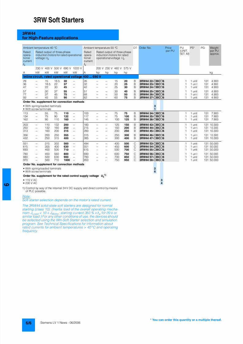
8122019 Arr Estado Solido
httpslidepdfcomreaderfullarr-estado-solido 1040
3RW Soft Starters
3RW44for High-Feature applications
1) Control by way of the internal 24 V DC supply and direct control by meansof PLC possible
NoteSoft starter selection depends on the motors rated current
The 3RW44 solid-state soft starters are designed for normalstarting (class 10) (Inertia load of the overall operating mecha- nism J Load lt 10 x J Motor starting current 350 x I e for 20 s orsimilar load) For any other conditions of use the devices shouldbe selected using the Win-Soft Starter selection and simulationprogram See Technical Specifications for information aboutrated currents for ambient temperatures gt 40 degC and operatingfrequency
Ambient temperature 40 degC Ambient temperature 50 degC DT Order No Priceper PU
PU(UNITSET M)
PS PG Weightper PUapprox
Ratedopera-
tionalcurrent I e
Rated output of three-phaseinduction motors for rated operational
voltage U e
Ratedopera-
tionalcurrent I e
Rated output of three-phaseinduction motors for rated
operational voltage U e
230 V 400 V 500 V 690 V 1000 V 200 V 230 V 460 V 575 V
A kW kW kW kW kW A hp hp hp hp kg
Inline circuit rated operational voltage 400 690 V
29 -- 15 185 30 -- 26 -- -- 15 20 B 3RW44 22-BC6 1 1 unit 131 490036 -- 185 22 37 -- 32 -- -- 20 25 B 3RW44 23-BC6 1 1 unit 131 490047 -- 22 30 45 -- 42 -- -- 25 30 B 3RW44 24-BC6 1 1 unit 131 4900
57 -- 30 37 55 -- 51 -- -- 30 40 B 3RW44 25-BC6 1 1 unit 131 490077 -- 37 45 75 -- 68 -- -- 50 50 B 3RW44 26-BC6 1 1 unit 131 490093 -- 45 55 90 -- 82 -- -- 60 75 B 3RW44 27-BC6 1 1 unit 131 4900
Order No supplement for connection methods
bull With spring-loaded terminals 3bull With screw terminals 1
113 -- 55 75 110 -- 100 -- -- 75 75 B 3RW44 34-BC6 1 1 unit 131 7900134 -- 75 90 132 -- 117 -- -- 75 100 B 3RW44 35-BC6 1 1 unit 131 7900
162 -- 90 110 160 -- 145 -- -- 100 125 B 3RW44 36-BC6 1 1 unit 131 7900
203 -- 110 132 200 -- 180 -- -- 125 150 B 3RW44 43-BC6 1 1 unit 131 10300250 -- 132 160 250 -- 215 -- -- 150 200 B 3RW44 44-BC6 1 1 unit 131 10300313 -- 160 200 315 -- 280 -- -- 200 250 B 3RW44 45-BC6 1 1 unit 131 10300
356 -- 200 250 355 -- 315 -- -- 250 300 B 3RW44 46-BC6 1 1 unit 131 10300432 -- 250 315 400 -- 385 -- -- 300 400 B 3RW44 47-BC6 1 1 unit 131 10300
551 -- 315 355 560 -- 494 -- -- 400 500 C 3RW44 53-BC6 1 1 unit 131 50000615 -- 355 400 630 -- 551 -- -- 450 600 C 3RW44 54-BC6 1 1 unit 131 50000693 -- 400 500 710 -- 615 -- -- 500 700 C 3RW44 55-BC6 1 1 unit 131 50000
780 -- 450 560 800 -- 693 -- -- 600 750 C 3RW44 56-BC6 1 1 unit 131 50000880 -- 500 630 900 -- 780 -- -- 700 850 C 3RW44 57-BC6 1 1 unit 131 50000970 -- 560 710 1000 -- 850 -- -- 750 950 C 3RW44 58-BC6 1 1 unit 131 50000
Order No supplement for connection methods
bull With spring-loaded terminals 2bull With screw terminals 6
Order No supplement for the rated control supply voltage U s1)
bull 115 V AC 3bull 230 V AC 4
8122019 Arr Estado Solido
httpslidepdfcomreaderfullarr-estado-solido 1140
3RW Soft Starters
3RW44for High-Feature applications
1) In the selection table the unit rated operational current I e refers to the
three-phase motors rated operational current in the inside-delta circuitThe actual current of the unit is approx 58 of this value
2) 3RW44 2 3RW44 3 and 3RW44 4 soft starters with screw-typeterminals delivery time class (preferred type)
3) Control by way of the internal 24 V DC supply and direct control by meansof PLC possible
NoteSoft starter selection depends on the motors rated current
The 3RW44 solid-state soft starters are designed for normalstarting (class 10) (Inertia load of the overall operatingmechanism JLoad lt 10 x JMotor starting current 350 x Ie for20 s or similar load) For any other conditions of use the devicesshould be selected using the Win-Soft Starter selection andsimulation program See Technical Specifications for informationabout rated currents for ambient temperatures gt 40 degC andoperating frequency
3RW44 27-1BC44 3RW44 36-6BC44 3RW44 47-6BC44 3RW44 58-6BC44
Ambient temperature 40 degC Ambient temperature 50 degC DT Order No Priceper PU
PU(UNITSET M)
PS PG Weightper PUapprox
Ratedopera-tionalcurrent I e
1)
Rated output of three-phase inductionmotors for rated operational voltageU e
Ratedopera-tionalcurrent I e
Rated output of three-phaseinduction motors for ratedoperational voltage U e
230 V 400 V 500 V 690 V 1000 V 200 V 230 V 460 V 575 V
A kW kW kW kW kW A hp hp hp hp kgInside-delta circuits rated operational voltage 200 460 V2)
50 15 22 -- -- -- 45 10 15 30 -- B 3RW44 22-BC4 1 1 unit 131 490062 185 30 -- -- -- 55 15 20 40 -- B 3RW44 23-BC4 1 1 unit 131 490081 22 45 -- -- -- 73 20 25 50 -- B 3RW44 24-BC4 1 1 unit 131 4900
99 30 55 -- -- -- 88 25 30 60 -- B 3RW44 25-BC4 1 1 unit 131 4900133 37 75 -- -- -- 118 30 40 75 -- B 3RW44 26-BC4 1 1 unit 131 4900161 45 90 -- -- -- 142 40 50 100 -- B 3RW44 27-BC4 1 1 unit 131 4900
Order No supplement for connection methods
bull With spring-loaded terminals 3bull With screw terminals 1
196 55 110 -- -- -- 173 50 60 125 -- B 3RW44 34-BC4 1 1 unit 131 7900232 75 132 -- -- -- 203 60 75 150 -- B 3RW44 35-BC4 1 1 unit 131 7900281 90 160 -- -- -- 251 75 100 200 -- B 3RW44 36-BC4 1 1 unit 131 7900
352 110 200 -- -- -- 312 100 125 250 -- B 3RW44 43-BC4 1 1 unit 131 10300433 132 250 -- -- -- 372 125 150 300 -- B 3RW44 44-BC4 1 1 unit 131 10300542 160 315 -- -- -- 485 150 200 400 -- B 3RW44 45-BC4 1 1 unit 131 10300
617 200 355 -- -- -- 546 150 200 450 -- B 3RW44 46-BC4 1 1 unit 131 10300748 250 400 -- -- -- 667 200 250 600 -- B 3RW44 47-BC4 1 1 unit 131 10300
954 315 560 -- -- -- 856 300 350 750 -- C 3RW44 53-BC4 1 1 unit 131 500001065 355 630 -- -- -- 954 350 400 850 -- C 3RW44 54-BC4 1 1 unit 131 500001200 400 710 -- -- -- 1065 350 450 950 -- C 3RW44 55-BC4 1 1 unit 131 50000
1351 450 800 -- -- -- 1200 450 500 1050 -- C 3RW44 56-BC4 1 1 unit 131 500001524 500 900 -- -- -- 1351 450 600 1200 -- C 3RW44 57-BC4 1 1 unit 131 500001680 560 1000 -- -- -- 1472 550 650 1300 -- C 3RW44 58-BC4 1 1 unit 131 50000
Order No supplement for connection methods
bull With spring-loaded terminals 2bull With screw terminals 6
Order No supplement for the rated control supply voltage U s3)
bull 115 V AC 3bull 230 V AC 4
You can order this quantity or a multiple thereof
8122019 Arr Estado Solido
httpslidepdfcomreaderfullarr-estado-solido 1240
3RW Soft Starters
3RW44for High-Feature applications
1) In the selection table the unit rated operational current I e refers to thethree-phase motors rated operational current in the inside-delta circuitThe actual current of the unit is approx 58 of this value
2) 3RW44 2 3RW44 3 and 3RW44 4 soft starters with screw-typeterminals delivery time class A
3) Control by way of the internal 24 V DC supply and direct control by meansof PLC possible
Accessories
NoteSoft starter selection depends on the motors rated current
The 3RW44 solid-state soft starters are designed for normalstarting (class 10) (Inertia load of the overall operatingmechanism J Load lt 10 x J Motor starting current 350 x I e for20 s or similar load) For any other conditions of use the devicesshould be selected using the Win-Soft Starter selection andsimulation program See Technical Specifications for informationabout rated currents for ambient temperatures gt 40 degC andoperating frequency
Ambient temperature 40 degC Ambient temperature 50 degC DT Order No Priceper PU
PU(UNITSET M)
PS PG Weightper PUapprox
Ratedopera-
tionalcurrent I e
1)
Rated output of three-phaseinduction motors for rated opera-
tional voltage U e
Ratedopera-
tionalcurrent I e
Rated output of three-phaseinduction motors for rated
operational voltage U e
230 V 400 V 500 V 690 V 1000 V 200 V 230 V 460 V 575 V
A kW kW kW kW kW A hp hp hp hp kg
Inside-delta circuits rated operational voltage 400 600 V2)
50 -- 22 30 -- -- 45 -- -- 30 40 B 3RW44 22-BC5 1 1 unit 131 490062 -- 30 37 -- -- 55 -- -- 40 50 B 3RW44 23-BC5 1 1 unit 131 490081 -- 45 45 -- -- 73 -- -- 50 60 B 3RW44 24-BC5 1 1 unit 131 4900
99 -- 55 55 -- -- 88 -- -- 60 75 B 3RW44 25-BC5 1 1 unit 131 4900133 -- 75 90 -- -- 118 -- -- 75 100 B 3RW44 26-BC5 1 1 unit 131 4900161 -- 90 110 -- -- 142 -- -- 100 125 B 3RW44 27-BC5 1 1 unit 131 4900
Order No supplement for connection methods
bull With spring-loaded terminals 3bull With screw terminals 1
196 -- 110 132 -- -- 173 -- -- 125 150 B 3RW44 34-BC5 1 1 unit 131 7900232 -- 132 160 -- -- 203 -- -- 150 200 B 3RW44 35-BC5 1 1 unit 131 7900
281 -- 160 200 -- -- 251 -- -- 200 250 B 3RW44 36-BC5 1 1 unit 131 7900
352 -- 200 250 -- -- 312 -- -- 250 300 B 3RW44 43-BC5 1 1 unit 131 10300433 -- 250 315 -- -- 372 -- -- 300 350 B 3RW44 44-BC5 1 1 unit 131 10300542 -- 315 355 -- -- 485 -- -- 400 500 B 3RW44 45-BC5 1 1 unit 131 10300
617 -- 355 450 -- -- 546 -- -- 450 600 B 3RW44 46-BC5 1 1 unit 131 10300748 -- 400 500 -- -- 667 -- -- 600 750 B 3RW44 47-BC5 1 1 unit 131 10300
954 -- 560 630 -- -- 856 -- -- 750 950 C 3RW44 53-BC5 1 1 unit 131 500001065 -- 630 710 -- -- 954 -- -- 850 1050 C 3RW44 54-BC5 1 1 unit 131 500001200 -- 710 800 -- -- 1065 -- -- 950 1200 C 3RW44 55-BC5 1 1 unit 131 50000
1351 -- 800 900 -- -- 1200 -- -- 1050 1350 C 3RW44 56-BC5 1 1 unit 131 500001524 -- 900 1000 -- -- 1351 -- -- 1200 1500 C 3RW44 57-BC5 1 1 unit 131 500001680 -- 1000 1200 -- -- 1472 -- -- 1300 1650 C 3RW44 58-BC5 1 1 unit 131 50000
Order No supplement for connection methods
bull With spring-loaded terminals 2bull With screw terminals 6
Order No supplement for the rated control supply voltage U s3)
bull 115 V AC 3bull 230 V AC 4
Forsoft starters Version DT Order No Priceper PU PU(UNITSET M)
PS PG Weightper PUapprox
Type kg
Soft Starter ES 2006 PC communication program
Soft Starter ES 2006 Smart
Parameterization and service software forSIRIUS 3RW44 soft starters for parameterizingthrough the system interface on the deviceExecutes on PCPG under Windows 2000XPwithout PC cableType of supply CD single license
3ZS1 313-1CC10-0YA0 1 1 unit 131 0230
3ZS1 313-1CC10-0YA0 Soft Starter ES 2006 Professional
Parameterization and service software forSIRIUS 3RW44 soft starters for parameterizingthrough the system interface on the device andPROFIBUS DP interface (PROFIBUS as optional commu-nication module necessary)Executes on PCPG under Windows 2000XPwithout PC cableType of supply CD single license
A 3ZS1 313-2CC10-0YA0 1 1 unit 131 0230
8122019 Arr Estado Solido
httpslidepdfcomreaderfullarr-estado-solido 1340
3RW Soft Starters
3RW44for High-Feature applications
Spare parts
Forsoft starters
Version DT Order No Priceper PU
PU(UNITSET M)
PS PG Weightper PUapprox
Type kg
PC cables
For PCPG communication with SIRIUS 3RW44soft starters
through the system interface for connecting tothe serial interface of the PCPG
B 3UF7 940-0AA00-0 1 1 unit 131 0150
Box terminal blocks for soft starters
Box terminal blocks
3RW44 2 Included in del ivery
3RW44 3 bull Up to 70 mm2 3RT19 55-4G 1 1 unit 101 0237
bull Up to 120 mm2 3RT19 56-4G 1 1 unit 101 0270
3RW44 3 bull Up to 240 mm2 3RT19 66-4G 1 1 unit 101 0676
PROFIBUS Communication moduleModule to be plugged into the soft starter to connect thesoft starter to the PROFIBUS net
A 3RW4 900-0KC00 1 1 unit 131 0320
External display and operation module
to show and operate the fonctions supplied by the softstarter via externally mounted display and operationmodule(for example in the cubicle door)
A 3RW4 900-0AC00 1 1 unit 131 0320
Connection cable
from serial interface of 3RW44 soft starter to external dis-play and operation modulebull Length 05 m flat B 3UF7 932-0AA00-0 1 1 unit 131 0020bull Length 05 m round A 3UF7 932-0BA00-0 1 1 unit 131 0050bull Length10 m round A 3UF7 937-0BA00-0 1 1 unit 131 0100bull Length25 m round A 3UF7 933-0BA00-0 1 1 unit 131 0150
Covers for soft starters
Terminal covers for box terminals
Additional touch protection to be fitted at the boxterminals (2 units required per device)
3RW44 2 and3RW44 3
3RT19 56-4EA2 1 1 unit 101 0028
3RW44 4 3RT19 66-4EA2 1 1 unit 101 0038
Terminal covers for cable lugs and busbarconnections
3RW44 2 and3RW44 3
3RT19 56-4EA1 1 1 unit 101 0067
3RW44 4 3RT19 66-4EA1 1 1 unit 101 0124
Forsoft starters
Version DT Order No Priceper PU
PU(UNITSET M)
PS PG Weightper PUapprox
Type kg
Fans
Fans
3RW44 2 and3RW44 3
115 VAC 3RW49 36-8VX30 1 1 unit 131 0300230 VAC 3RW49 36-8VX40 1 1 unit 131 0300
3RW44 4 115 V AC 3RW49 47-8VX30 1 1 unit 131 0500230 VAC 3RW49 47-8VX40 1 1 unit 131 0500
3RW44 5 115 V AC 3RW49 57-8VX30 1 1 unit 131 0800230 VAC 3RW49 57-8VX40 1 1 unit 131 0800
You can order this quantity or a multiple thereof
8122019 Arr Estado Solido
httpslidepdfcomreaderfullarr-estado-solido 1440
3RW Soft Starters
3RW44for High-Feature applications
Function
Equipped with modern ergonomic user prompting theSIRIUS 3RW44 soft starters can be commissioned quickly and
easily using a keypad and a menu-prompted multi-line displaywith background lighting Motor starting and deceleration areoptimized quickly easily and safely with just a few settings in aselectable language Four-key operation and plain-text displaysfor each menu point guarantee full clarity at every moment of theparameterization and operation Measurement values and oper-ating values as well as warning messages and fault indicationsare output continuously on the front panel during operation andwhen control voltage is applied An external display and opera-tor module can be connected by means of a connecting cableto the soft starter thus enabling active indications and the like tobe read directly from the control cabinet door
The SIRIUS 3RW44 soft starters are equipped with optimumfunctionality An integral bypass contact system reduces thepower loss of the soft starter during operation This reliablyprevents heating of the switchgear environment TheSIRIUS 3RW44 soft starters have internal intrinsic deviceprotection This prevents thermal overloading of the powersections thyristors eg due to unacceptably high closingoperations
Wiring work for installing an additional motor overload relay is nolonger needed as the SIRIUS 3RW44 soft starters perform thisfunction too In addition they offer adjustable trip classes and athermistor motor protection function As an option the thyristorscan also be protected by SITOR semi-conductor fuses fromshort-circuiting And even inrush current peaks are reliablyavoided thanks to adjustable current limiting
As a further option the SIRIUS 3RW44 soft starters can beupgraded with a PROFIBUS DP module Thanks to their commu-nication capability and their programmable control inputs andrelay outputs the SIRIUS 3RW44 soft starters can be very easily
and quickly integrated in higher-level controllersIn addition a creep speed function is available for positioningand setting jobs With this function the motor can be controlledin both directions of rotation with reduced torque and an adjust-able low speed
On the other hand the SIRIUS 3RW44 soft starters offer a newcombined DC braking function for the fast stopping of drivingloads
Highlights bull Soft starting with breakaway pulse torque control or voltage
ramp and adjustable torque or current limiting as well as anycombination of these depending on load type
bull Integrated bypass contact system to minimize dissipatedpower
bull Various setting options for the starting parameters such asstarting torque starting voltage ramp-up and ramp-downtime and much more in three separate parameter sets
bull Start-up detectionbull Inside-delta circuit for savings in terms of size and equipment
costsbull Various ramp-down modes selectable free ramp-down
torque-controlled pump stopping combined DC brakingbull Solid-state motor overload and intrinsic device protectionbull Thermistor motor protectionbull Keypad with a menu-controlled multi-line graphic display with
background lighting
bull Interface for communication with the PC for more accuratesetting of the parameters as well as for control and monitoringbull Simple adaptation to the motor feederbull Simple mounting and commissioningbull Display of operating states and fault signalsbull Connection to PROFIBUS with optional PROFIBUS DP modulebull External display and operator modulebull System voltages from 200 to 690 V 50 to 60 Hzbull Applicable up to 60 degC (derating from 40 degC)
8122019 Arr Estado Solido
httpslidepdfcomreaderfullarr-estado-solido 1540
3RW Soft Starters
3RW44for High-Feature applications
Technical specifications
Type 3RW44 -BC3 3RW44 -BC4Terminal
Control electronics
Rated valuesRated control supply voltage A1A2PE V 115 AC 230 ACbull Tolerance -15+10 -15+10Rated control supply current STANDBY mA 30 20
Rated control supply current ONbull 3RW44 2 mA 300 170bull 3RW44 3 mA 500 250bull 3RW44 4 mA 750 400bull 3RW44 5 mA 450 200
Maximum current (pickup bypass)bull 3RW44 2 mA 1000 500bull 3RW44 3 mA 2500 1250bull 3RW44 4 mA 6000 3000bull 3RW44 5 mA 4500 2500
Rated frequency Hz 50 60 50 60bull Tolerance plusmn10 plusmn10
Type 3RW44 Terminal Factory presetting
Control electronics
Control inputsInput 1 IN1 Start motor right parameter set 1Input 2 IN2 No actionInput 3 IN3 No actionInput 4 IN4 Trip reset
Supply L+L-bull Rated operational current mA Approx 10 per input to DIN 19240bull Rated operational voltage L+ Internal voltage 24 V DC from inter-
nal supply through terminal L+ toIN1 IN4 Maximum load at L+approx 55 mA
L- External voltage DC external voltage(to DIN19240) through terminals
L- and IN1 IN4(min 12 V DC max 30 V DC)
Thermistor motor protection inputInput T1T2 PTC type A or Thermoclick Deactivated
Relay outputs (floating auxiliary contacts)Output 1 1314 ON periodOutput 2 2324 No actionOutput 3 3334 No actionOutput 4 959698 Group fault
Switching capacity of the relay outputs230 VAC-15 A 3 at 240 V24 VDC-13 A 1 at 24 VProtection against overvoltages Protection by means of Varistor through relay contactShort-circuit protection 4 A gLgG operational class
6 A quick (fuse is not included in scope of supply)
Protective functions
Motor protection functionsTrips in the event of Thermal overloading of the motor
Trip class to IEC 60947-4-1 Class 510152030 10Phase failure sensitivity gt 40
Overload warning yesReset and recovery ManualAutomatic ManualReset option after tripping ManualAutomatic ManualRecovery time min 1 30 1
Device protection functionsTrips in the event of Thermal overloading of the thyristorsReset option after tripping ManualAutomatic ManualRecovery time min 05
8122019 Arr Estado Solido
httpslidepdfcomreaderfullarr-estado-solido 1640
3RW Soft Starters
3RW44for High-Feature applications
Type 3RW44 Factory presetting
Control times and parameters
Control timesClosing delay (with connected control voltage) ms lt 50Closing delay (automatic mode) ms lt 4000Recovery time (closing command in active ramp-down) ms lt 100
Mains failure bridging timeControl supply voltage ms 100
Mains failure response timeLoad current circuit ms 100
Reclosing lockout after overload tripMotor protection trip min 1 30 1Device protection trip s 30
Setting options for startingVoltage ramp for starting voltage 20 100 30Torque control for starting torque 20 100 50Torque control for limit torque 20 200 150
Starting time s 0 360 20Maximum starting time s 1 1000 DeactivatedCurrent limit value 125 550 450
Breakaway voltage 40 100 80Breakaway time s 0 2 DeactivatedMotor heat output 0 100 0
Creep mode LeftRight runningSpeed factor as function of rated speed (n = n rated factor) 3 21 7Creep torque (reference variable depends on the motor used but isalways smaller than the rated torque of the motor)
20 100 50
Setting options for ramp-downTorque control for stopping torque 10 100 10Ramp-down time s 0 360 10Dynamic braking torque 20 100 50DC braking torque 20 100 50
Operating indicationsTest voltageTest mains phasesReady to start
Start active
Motor runningRamp-down active
Warningserror signalsMains voltage missingLeading-edge phase error
Phase failurebull L1bull L2bull L3
Missing load phasebull T1bull T2bull T3
Failurebull Contact element 1 (thyristor)bull Contact element 2 (thyristor)bull Contact element 3 (thyristor)
Flash memory faulty
Supply voltagebull Below 75 bull Below 85 bull Over 110
Current unbalance exceededThermal motor model overload
Prewarning limit exceededbull Motor heatingbull Time-related trip reserve
Bypass elements defectiveMains voltage too high
Device not namedWrong naming versionCurrent range exceeded
Motor blocking ndash shutdownCurrent limit exceeded
Power section
bull Overheatedbull OvertemperatureEmergency active
8122019 Arr Estado Solido
httpslidepdfcomreaderfullarr-estado-solido 1740
3RW Soft Starters
3RW44for High-Feature applications
1) Parameter motor left possible only in conjunction with creep mode
Type 3RW44 Factory presetting
Control times and parameters
Warningserror signals (contd)Temperature sensorbull Overloadbull Open-circuitbull Short-circuit
Ground faultbull Detectedbull Shutdown
Connection abort in manual modeMax number of starts exceeded I e limit value overshootundershoot
Cooling timebull Motor activebull Switch block active
Heat sink sensorbull Open-circuitbull Short-circuit
Quick-stop functionSwitch block faulty I e class setting not permissible
Control inputsInput 1 Motor right parameter set 1Input 2 No actionInput 3 No actionInput 4 Trip reset
Parameterizing options for control inputs 1 4 No actionLocal manual modeEmergency startCreep speedQuick-stopTrip reset
Motor right parameter set 1Motor left parameter set 11) Motor right parameter set 2Motor left parameter set 21) Motor right parameter set 3Motor left parameter set 31)
Relay outputsOutput 1 ON periodOutput 2 No actionOutput 3 No actionOutput 4 Group fault
Parameterizing options for relay outputs 1 3 No actionPAA output 1PAA output 2
Input 1Input 2Input 3Input 4
Ramp-upOperationBypassRamp-downON periodCommand motor on
FanDC braking contactor
Group warningGroup faultBus faultDevice error
Power onReady to start
Motor temperature sensors Deactivated DeactivatedThermoclickPTC type A
8122019 Arr Estado Solido
httpslidepdfcomreaderfullarr-estado-solido 1840
3RW Soft Starters
3RW44for High-Feature applications
1) Current limit on soft starter set to 350 I M
2) For intermittent duty S4 with ON period = 70 T u = 40 degC stand-aloneinstallation vertical The quoted operating frequencies do not apply forautomatic mode
3) Maximum adjustable rated motor current I M dependent on CLASS setting
Type 3RW44 -BC4 3RW44 -BC5 3RW44 -BC6
Power electronics
Rated operational voltage for inline circuit V 200 460 AC 400 600 AC 400 690 AC
Tolerance -15+10 -15+10 -15+10Rated operational voltage for inside-delta circuit V 200 460 AC 400 600 AC 400 600 ACTolerance -15+10 -15+10 -15+10
Rated frequency Hz 50 60Tolerance plusmn10
Continuous operation at 40 degC ( of I e) 115
Minimum load ( of set motor current I M) 8
Maximum conductor length between soft starter and motor m 200
Permissible installation height m 5000 (derating from 1000 see characteristics) higher on request
Permissible mounting position
Permissible ambient temperatureOperation degC 0 +60 (derating from +40)Storage degC -25 +80
Degree of protection IP00
Type 3RW44 22 3RW44 23 3RW44 24 3RW44 25 3RW44 26 3RW44 27
Power electronics
Rated operational current I e 29 36 47 57 77 93
Load rating with rated operational current I ebull Acc to IEC and ULCSA for individual mounting
at 405060 degC AC-53a A 292623 363229 474237 575145 776859 938272
Smallest adjustable rated motor current I Mfor the motor overload protection
A 5 7 9 11 15 18
Power lossbull In operation after completed ramp-up with uninterrupted rated
operational current (40 degC) approx W 8 10 32 36 45 55bull During starting with current limit set to 350 I M (40 degC) W 400 470 600 725 940 1160
Permissible rated motor current and starts per hour
bull Normal starting (Class 5)- Rated motor current I M
1) starting time 5 s A 29 36 47 57 77 93- Starts per hour2) 1h 41 34 41 41 41 41
- Rated motor current I M1)3) starting time 10 s A 29 36 47 57 77 93
- Starts per hour2) 1h 20 15 20 20 20 20
bull Normal starting (Class 10)- Rated motor current I M
1) starting time 10 s A 29 36 47 57 77 93- Starts per hour2) 1h 20 15 20 20 20 20
- Rated motor current I M1)3) starting time 20 s A 29 36 47 57 77 93
- Starts per hour2) 1h 10 6 10 10 8 8
bull Normal starting (Class 15)- Rated motor current I M
1) starting time 15 s A 29 36 47 57 77 93- Starts per hour2) 1h 13 9 13 13 13 13
- Rated motor current I M1)3) starting time 30 s A 29 36 47 57 77 93
- Starts per hour2) 1h 6 4 6 6 6 6
bull For heavy starting (Class 20)- Rated motor current I M
1) starting time 20 s A 29 36 47 57 73 88- Starts per hour2) 1h 10 6 10 10 10 10
- Rated motor current I M1)3) starting time 40 s A 29 36 47 57 73 88
- Starts per hour2) 1h 4 2 4 5 18 08
bull For very heavy starting (Class 30)- Rated motor current I M
1) starting time 30 s A 29 36 44 57 65 77- Starts per hour2) 1h 6 4 6 6 6 6
- Rated motor current I M1)3) starting time 60 s A 29 36 44 57 65 77
- Starts per hour2) 1h 18 08 33 15 2 1
8122019 Arr Estado Solido
httpslidepdfcomreaderfullarr-estado-solido 1940
3RW Soft Starters
3RW44for High-Feature applications
1) Current limit on soft starter set to 350 I M
2) For intermittent duty S4 with ON period = 70 T u = 40 degC stand-aloneinstallation vertical The quoted operating frequencies do not apply forautomatic mode
3) Maximum adjustable rated motor current I M dependent on CLASS setting
Type 3RW44 34 3RW44 35 3RW44 36
Power electronics
Rated operational current I e 113 134 162
Load rating with rated operational current I ebull Acc to IEC and ULCSA for individual mounting AC-53a
- at 40 degC A 113 134 162- at 50 degC A 100 117 145- at 60 degC A 88 100 125
Smallest adjustable rated motor current I Mfor the motor overload protection
A 22 26 32
Power lossbull In operation after completed ramp-up with uninterrupted rated
operational current (40 degC) approx W 64 76 95bull During starting with current limit set to 350 I M (40 degC) W 1350 1700 2460
Permissible rated motor current and starts per hour
bull Normal starting (Class 5)- Rated motor current I M
1) starting time 5 s A 113 134 162- Starts per hour2) 1h 41 39 41
- Rated motor current I M1)3) starting time 10 s A 113 134 162
- Starts per hour2) 1h 20 15 20
bull Normal starting (Class 10)- Rated motor current I M
1) starting time 10 s A 113 134 162- Starts per hour2) 1h 20 15 20
- Rated motor current I M1)3) starting time 20 s A 113 134 162
- Starts per hour2) 1h 9 6 7
bull Normal starting (Class 15)- Rated motor current I M
1) starting time 15 s A 113 134 162- Starts per hour2) 1h 13 9 12
- Rated motor current I M1)3) starting time 30 s A 113 134 162
- Starts per hour2) 1h 6 6 1
bull For heavy starting (Class 20)- Rated motor current I M
1) starting time 20 s A 106 125 147- Starts per hour2) 1h 9 9 10
- Rated motor current I M1)3) starting time 40 s A 106 125 147
- Starts per hour2) 1h 15 2 1
bull For very heavy starting (Class 30)- Rated motor current I M
1) starting time 30 s A 91 110 120
- Starts per hour2) 1h 6 6 6- Rated motor current I M
1)3) starting time 60 s A 91 110 120- Starts per hour2) 1h 2 2 2
8122019 Arr Estado Solido
httpslidepdfcomreaderfullarr-estado-solido 2040
3RW Soft Starters
3RW44for High-Feature applications
1) Current limit on soft starter set to 350 I M
2) For intermittent duty S4 with ON period = 70 T u = 40 degC stand-aloneinstallation vertical The quoted operating frequencies do not apply forautomatic mode
3) Maximum adjustable rated motor current I M dependent on CLASS setting
Type 3RW44 43 3RW44 44 3RW44 45 3RW44 46 3RW44 47
Power electronics
Rated operational current I e 203 250 313 356 432
Load rating with rated operational current I ebull Acc to IEC and ULCSA for individual mounting AC-53a
- at 40 degC A 203 250 313 356 432- at 50 degC A 180 215 280 315 385- at 60 degC A 156 185 250 280 335
Smallest adjustable rated motor current I Mfor the motor overload protection
A 40 50 62 71 86
Power lossbull In operation after completed ramp-up with uninterrupted rated
operational current (40 degC) approx W 89 110 145 174 232bull During starting with current limit set to 350 I M (40 degC) W 3350 4000 4470 5350 5860
Permissible rated motor current and starts per hour
bull Normal starting (Class 5)- Rated motor current I M
1) starting time 5 s A 203 250 313 356 432- Starts per hour2) 1h 41 41 41 41 39
- Rated motor current I M1)3) starting time 10 s A 203 250 313 356 432
- Starts per hour2) 1h 20 20 19 17 16
bull Normal starting (Class 10)- Rated motor current I M
1) starting time 10 s A 203 250 313 356 432- Starts per hour2) 1h 20 20 19 17 16
- Rated motor current I M1)3) starting time 20 s A 203 250 313 356 432
- Starts per hour2) 1h 9 10 6 4 5
bull Normal starting (Class 15)- Rated motor current I M
1) starting time 15 s A 203 240 313 325 402- Starts per hour2) 1h 13 13 10 13 11
- Rated motor current I M1)3) starting time 30 s A 203 240 313 325 402
- Starts per hour2) 1h 3 6 1 2 1
bull For heavy starting (Class 20)- Rated motor current I M
1) starting time 20 s A 195 215 275 285 356- Starts per hour2) 1h 10 10 10 10 10
- Rated motor current I M1)3) starting time 40 s A 195 215 275 285 356
- Starts per hour2) 1h 1 5 1 3 1
bull For very heavy starting (Class 30)- Rated motor current I M
1) starting time 30 s A 162 180 220 240 285
- Starts per hour2) 1h 6 6 6 6 6- Rated motor current I M
1)3) starting time 60 s A 162 180 220 240 285- Starts per hour2) 1h 3 3 3 2 1
8122019 Arr Estado Solido
httpslidepdfcomreaderfullarr-estado-solido 2140
3RW Soft Starters
3RW44for High-Feature applications
1) Current limit on soft starter set to 350 I M
2) For intermittent duty S4 with ON period = 70 T u = 40 degC stand-aloneinstallation vertical The quoted operating frequencies do not apply forautomatic mode
3) Maximum adjustable rated motor current I M dependent on CLASS setting
Type 3RW44 53 3RW44 54 3RW44 55 3RW44 56 3RW44 57 3RW44 58
Power electronics
Rated operational current I e 551 615 693 780 880 970
Load rating with rated operational current I ebull Acc to IEC and ULCSA for individual mounting AC-53a
- at 40 degC A 551 615 693 780 880 970- at 50 degC A 494 551 615 693 780 850- at 60 degC A 438 489 551 615 693 760
Smallest adjustable rated motor current I Mfor the motor overload protection
A 110 123 138 156 176 194
Power lossbull In operation after completed ramp-up with uninterrupted rated
operational current (40 degC) approx W 159 186 220 214 250 270bull During starting with current limit set to 350 I M (40 degC) W 7020 8100 9500 11100 13100 15000
Permissible rated motor current and starts per hour
bull Normal starting (Class 5)- Rated motor current I M
1) starting time 5 s A 551 615 693 780 880 970- Starts per hour2) 1h 41 41 37 33 22 17
- Rated motor current I M1)3) starting time 10 s A 551 615 693 780 880 970
- Starts per hour2) 1h 20 20 16 13 8 5
bull Normal starting (Class 10)- Rated motor current I M
1) starting time 10 s A 551 615 693 780 880 970- Starts per hour2) 1h 20 20 16 13 8 5
- Rated motor current I M1)3) starting time 20 s A 551 615 693 780 880 970
- Starts per hour2) 1h 10 9 6 4 03 03
bull Normal starting (Class 15)- Rated motor current I M
1) starting time 15 s A 551 615 666 723 780 821- Starts per hour2) 1h 13 13 11 9 8 8
- Rated motor current I M1)3) starting time 30 s A 551 615 666 723 780 821
- Starts per hour2) 1h 6 4 3 1 04 05
bull For heavy starting (Class 20)- Rated motor current I M
1) starting time 20 s A 551 591 633 670 710 740- Starts per hour2) 1h 10 10 7 8 8 9
- Rated motor current I M1)3) starting time 40 s A 551 591 633 670 710 740
- Starts per hour2) 1h 4 2 1 1 04 1
bull For very heavy starting (Class 30)- Rated motor current I M
1) starting time 30 s A 500 525 551 575 600 630
- Starts per hour2) 1h 6 6 6 6 6 6- Rated motor current I M
1)3) starting time 60 s A 500 525 551 575 600 630- Starts per hour2) 1h 2 1 1 1 15 1
8122019 Arr Estado Solido
httpslidepdfcomreaderfullarr-estado-solido 2240
3RW Soft Starters
3RW44for High-Feature applications
1) When connecting cable lugs to DIN 46235 use 3RT19 56-4EA1 terminalcover for conductor cross-sections from 95 mmsup2 to ensure phase spacing
2) When connecting cable lugs to DIN 46234 the 3RT19 66-4EA1 terminalcover must be used for conductor cross-sections of 240 mmsup2 and more aswell as DIN 46235 for conductor cross-sections of 185 mmsup2 and more tokeep the phase clearance
Type 3RW44 2 3RW44 3 3RW44 4 3RW44 5
Conductor cross-sections
Screw
terminals
Main conductors
with box terminal 3RT19 55-4G (55 kW) 3RT19 66-4G
Front clampingpoint connected
bull Finely stranded with end sleeve mm2 16 70 70 240bull Finely stranded without end sleeve mm2 16 70 70 240bull Stranded mm2 16 70 95 300
bull Ribbon cable conductors(number x width x thickness)
mm min 3 x 9 x 08max 6 x 155 x 08
min 6 x 9 x 08max 20 x 24 x 05
bull AWG conductors solid or stranded AWG 6 20 30 600 kcmil
Rear clamping pointconnected
bull Finely stranded with end sleeve mm2 16 70 120 185bull Finely stranded without end sleeve mm2 16 70 120 185bull Stranded mm2 16 70 120 240
bull Ribbon cable conductors(number x width x thickness)
mm min 3 x 9 x 08max 6 x 155 x 08
min 6 x 9 x 08max 20 x 24 x 05
bull AWG conductors solid or stranded AWG 6 20 250 500 kcmil
Both clamping
points connected
bull Finely stranded with end sleeve mm2 max 1 x 50 1 x 70 min 2 x 50 max 2 x 185
bull Finely stranded without end sleeve mm2 max 1 x 50 1 x 70 min 2 x 50 max 2 x 185bull Stranded mm2 max 2 x 70 max 2 x 70 max 2 x 240
bull Ribbon cable conductors(number x width x thickness)
mm max 2 x (6 x 155 x 08) max 2 x (20 x 24 x 05)
bull AWG conductors solid or stranded AWG max 2 x 10 min 2 x 20max 2 x 500 kcmil
bull Terminal screws M10 (hexagon socket AF4) M12 (hexagon socket AF5)- Pickup torque 10 12 20 22
90 110 180 195
Screwterminals
Main conductors
with box terminal 3RT19 56-4G
Front or rear clamp-ing point connected
bull Finely stranded with end sleeve mm2 16 120bull Finely stranded without end sleeve mm2 16 120bull Stranded mm2 16 120
bull Ribbon cable conductors(number x width x thickness)
mm min 3 x 9 x 08max 6 x 155 x 08
bull AWG conductors solid or stranded AWG 6 250 kcmil
Both clampingpoints connected
bull Finely stranded with end sleeve mm2 max 1 x 95 1 x 120bull Finely stranded without end sleeve mm2 max 1 x 95 1 x 120bull Stranded mm2 max 2 x 120
bull Ribbon cable conductors(number x width x thickness)
mm max 2 x (10 x 155 x 08)
bull AWG conductors solid or stranded AWG max 2 x 30
Screwterminals
Main conductors
Without box terminalrail connection
bull Finely stranded with cable lug mm2 16 951) 50 2402) 50 2402)
bull Stranded with cable lug mm2 25 1201) 70 2402) 70 2402)
bull AWG conductors solid or stranded AWG 4 250 kcmil 20 500 kcmil 10 500 kcmil
bull Connecting bar (max width) mm 17 25 60
bull Terminal screws M8 x 25 (AF13) M10 x 30 (AF17) M12 x 40- Pickup torque NM 10 14 14 24 20 35lbin 89 124 124 210 177 310
8122019 Arr Estado Solido
httpslidepdfcomreaderfullarr-estado-solido 2340
3RW Soft Starters
3RW44for High-Feature applications
Soft starters Type 3RW44
Conductor cross-sections
Auxiliary conductors (1 or 2 conductors can be connected)
Screw terminals
bull Solid mm2 2 x 05 25bull Finely stranded with end sleeve mm2 2 x 05 15
bull AWG cables- Solid or stranded AWG 2 x 20 14- Finely stranded with end sleeve AWG 2 x 20 16
bull Terminal screws- Pickup torque NM 07 09
lbin 7 8
Spring-loaded terminals
bull Solid mm2 2 x 025 25bull Finely stranded with end sleeve mm2 2 x 025 15bull AWG conductors solid or stranded AWG 2 x 24 14
Standard Parameters
Electromagnetic compatibility acc to EN 60947-4-2
EMC interference immunityElectrostatic discharge (ESD) EN 61000-4-2 plusmn4 kV contact discharge plusmn8 kV air discharge
Electromagnetic RF fields EN 61000-4-3 Frequency range 80 1000 MHz with 80 at 1 kHzDegree of severity 3 10 Vm
Conducted RF interference EN 61000-4-6 Frequency range 150 kHz 80 MHz with 80 at 1 kHzInterference 10 V
RF voltages and RF currents on conductorsBurst EN 61000-4-4 plusmn2 kV5 kHzSurge EN 61000-4-5 plusmn1 kV line to line
plusmn2 kV line to ground
EMC interference emission
EMC interference field strength EN55011 Limit value of Class A at 30 1000 MHz
Radio interference voltage EN55011 Limit value of Class A at 015 30 MHz
Is an RI suppression filter necessary
Degree of noise suppression A (industrial applications) no
8122019 Arr Estado Solido
httpslidepdfcomreaderfullarr-estado-solido 2440
3RW Soft Starters
3RW44for High-Feature applications
Fuse assignment
The coordination type to which the motor feeder with soft starteris mounted depends on the application-specific requirements
Normally fuseless mounting (combination of motor starter pro-tector and soft starter) is sufficient If type 2 coordination is to befulfilled semiconductor fuses must be fitted in the motor feeder
1) The rated motor current must be considered when selecting the devices
2) The types of coordination are explained in more detail in theTechnical information LV 1 T under ndash Fuseless Load Feeders
Inline circuit fuseless version
Soft starters Motor starter protectorscircuit-breakers1)
Rated current 440 V +10 Rated currentG1 Q1Type A Type A
Type of coordination 12) 3RW44 22 3RW44 27 I q = 32 kA 3RW44 34 and 3RW44 35 I q = 16 kA 3RW44 36 3RW44 57 I q = 65 kA
3RW44 22 29 3RV10 42-4HA10 503RW44 23 36 3RV10 42-4JA10 633RW44 24 47 3RV10 42-4KA10 75
3RW44 25 57 3RV10 42-4LA10 903RW44 26 77 3RV10 42-4MA10 1003RW44 27 93 3RV10 42-4MA10 100
3RW44 34 113 3VL17 16-2DD36 1603RW44 35 134 3VL17 16-2DD36 1603RW44 36 162 3VL37 25-2DC36 250
3RW44 43 203 3VL47 31-3DC36 3153RW44 44 250 3VL47 31-3DC36 3153RW44 45 313 3VL47 40-3DC36 400
3RW44 46 356 3VL47 40-3DC36 4003RW44 47 432 3VL57 50-3DC36 500
3RW44 53 551 3VL67 80-3DE36 8003RW44 54 615 3VL67 80-3DE36 8003RW44 55 693 3VL67 80-3DE36 800
3RW44 56 780 3VL77 10-3AB36 10003RW44 57 880 3VL77 10-3AB36 10003RW44 58 970 3VL77 12-3AB36 1200
8122019 Arr Estado Solido
httpslidepdfcomreaderfullarr-estado-solido 2540
3RW Soft Starters
3RW44for High-Feature applications
1) If the ramp-down function Combined braking is selected no brakingcontactor is requiredIf the ramp-down function DC braking is selected a braking contactormust also be used (see table for type)For applications with large centrifugal masses (J Load gt J Motor) werecommend the function DC braking
2) Additional auxiliary relay K4LZXRT4A4T30(3RW44 soft starter with rated control supply voltage 230 V AC)LZXRT4A4S15(3RW44 soft starter with rated control supply voltage 115 V AC)
3) The types of coordination are explained in more detail in theTechnical information LV 1 T under ndash Fuseless Load Feeders
Inline circuit fused version (line protection only)
Soft starters Line protections Line contactorsup to 400 V
Braking contactors1)2)
Rated current 690 V +5 Rated current Size (optional) (for typical circuit see page 633)G1 F1 K1 K2 K3Type A Type A Type Type Type
Type of coordination 13) I q = 65 kA
3RW44 22 29 3NA3 820-6 50 00 3RT10 34 3RT15 26 --3RW44 23 36 3NA3 822-6 63 00 3RT10 35 3RT15 26 --
3RW44 24 47 3NA3 824-6 80 00 3RT10 36 3RT15 35 --3RW44 25 57 3NA3 830-6 100 00 3RT10 44 3RT15 35 --3RW44 26 77 3NA3 132-6 125 1 3RT10 45 3RT10 24 3RT10 353RW44 27 93 3NA3 136-6 160 1 3RT10 46 3RT10 25 3RT10 36
3RW44 34 113 3NA3 244-6 250 2 3RT10 54 3RT10 34 3RT10 443RW44 35 134 3NA3 244-6 250 2 3RT10 55 3RT10 36 3RT10 453RW44 36 162 3NA3 365-6 500 3 3RT10 56 3RT10 44 3RT10 45
3RW44 43 203 2 x 3NA3 354-6 2 x 355 3 3RT10 64 3RT10 44 3RT10 543RW44 44 250 2 x 3NA3 354-6 2 x 355 3 3RT10 65 3RT10 44 3RT10 553RW44 45 313 2 x 3NA3 365-6 2 x 500 3 3RT10 75 3RT10 54 3RT10 56
3RW44 46 356 2 x 3NA3 365-6 2 x 500 3 3RT10 75 3RT10 54 3RT10 563RW44 47 432 2 x 3NA3 365-6 2 x 500 3 3RT10 76 3RT10 55 3RT10 64
3RW44 53 551 2 x 3NA3 365-6 2 x 500 3 3TF68 44-0CM7 3TF68 44-0CM7 3TF68 44-0CM73RW44 54 615 2 x 3NA3 365-6 2 x 500 3 3TF68 44-0CM7 3TF68 44-0CM7 3TF68 44-0CM73RW44 55 693 2 x 3NA3 365-6 2 x 500 3 3TF69 44-0CM7 3TF69 44-0CM7 3TF69 44-0CM7
3RW44 56 780 2 x 3NA3 365-6 2 x 500 3 3TF69 44-0CM7 3TF69 44-0CM7 3TF69 44-0CM73RW44 57 880 2 x 3NA3 365-6 2 x 500 3 2 x 3TF69 44-0CM7 2 x 3TF69 44-0CM7 2 x 3TF69 44-0CM7
3RW44 58 970 3 x 3NA3 365-6 3 x 500 3
8122019 Arr Estado Solido
httpslidepdfcomreaderfullarr-estado-solido 2640
3RW Soft Starters
3RW44for High-Feature applications
1) If the ramp-down function Combined braking is selected no brakingcontactor is requiredIf the ramp-down function DC braking is selected a braking contactormust also be used (see table for type)For applications with large centrifugal masses (J Load gt J Motor) werecommend the function DC braking
2) Additional auxiliary relay K4LZXRT4A4T30(3RW44 soft starter with rated control supply voltage 230 V AC)LZXRT4A4S15(3RW44 soft starter with rated control supply voltage 115 V AC)
3) The types of coordination are explained in more detail in theTechnical information LV 1 T under ndash Fuseless Load Feeders
Inline circuit fused version with 3NE1 SITOR all-range fuse (semiconductor and line protection)
Soft starters All-range fuses Line contactors upto 400 V
Braking contactors1)2)
Ratedcurrent
Rated current Voltage Size (optional) (for typical circuit see page 633)
G1 Frsquo1 K1 K2 K3Type A Type A V Type Type Type
Type of coordination 23) I q = 65 kA
3RW44 22 29 3NE1 020-2 80 690 +5 00 3RT10 34 3RT15 26 --
3RW44 23 36 3NE1 020-2 80 690 +5 00 3RT10 35 3RT15 26 --3RW44 24 47 3NE1 021-2 100 690 +5 00 3RT10 36 3RT15 35 --
3RW44 25 57 3NE1 022-2 125 690 +5 00 3RT10 44 3RT15 35 --3RW44 26 77 3NE1 022-2 125 690 +5 00 3RT10 45 3RT10 24 3RT10 353RW44 27 93 3NE1 024-2 160 690 +5 1 3RT10 46 3RT10 25 3RT10 36
3RW44 34 113 3NE1 225-2 200 690 +5 1 3RT10 54 3RT10 34 3RT10 443RW44 35 134 3NE1 227-2 250 690 +5 1 3RT10 55 3RT10 36 3RT10 453RW44 36 162 3NE1 227-2 250 690 +5 1 3RT10 56 3RT10 44 3RT10 45
3RW44 43 203 3NE1 230-2 315 600 +10 1 3RT10 64 3RT10 44 3RT10 543RW44 44 250 3NE1 331-2 350 460 +10 2 3RT10 65 3RT10 44 3RT10 553RW44 45 313 3NE1 333-2 450 690 +5 2 3RT10 75 3RT10 54 3RT10 56
3RW44 46 356 3NE1 334-2 500 690 +5 2 3RT10 75 3RT10 54 3RT10 563RW44 47 432 3NE1 435-2 560 690 +5 3 3RT10 76 3RT10 55 3RT10 64
3RW44 53 551 2 x 3NE1 334-2 500 690 +10 2 3TF68 44-0CM7 3TF68 44-0CM7 3TF68 44-0CM73RW44 54 615 2 x 3NE1 334-2 500 690 +10 2 3TF68 44-0CM7 3TF68 44-0CM7 3TF68 44-0CM73RW44 55 693 2 x 3NE1 334-2 500 690 +10 2 3TF69 44-0CM7 3TF69 44-0CM7 3TF69 44-0CM7
3RW44 56 780 2 x 3NE1 435-2 560 690 +10 3 3TF69 44-0CM7 3TF69 44-0CM7 3TF69 44-0CM7
3RW44 57 880 2 x 3NE1 435-2 560 690 +10 3 2 x 3TF69 44-0CM7 2 x 3TF69 44-0CM7 2 x 3TF69 44-0CM73RW44 58 970 2 x 3NE1 435-2 560 690 +10 3
8122019 Arr Estado Solido
httpslidepdfcomreaderfullarr-estado-solido 2740
3RW Soft Starters
3RW44for High-Feature applications
1) If the ramp-down function Combined braking is selected no brakingcontactor is requiredIf the ramp-down function DC braking is selected a braking contactor
must also be used (see table for type)For applications with large centrifugal masses (J Load gt J Motor) werecommend the function DC braking
2) Additional auxiliary relay K4LZXRT4A4T30(3RW44 soft starter with rated control supply voltage 230 V AC)
LZXRT4A4S15(3RW44 soft starter with rated control supply voltage 115 V AC)
3) The types of coordination are explained in more detail in theTechnical information LV 1 T under ndash Fuseless Load Feeders
Inline circuit fused version with 3NE or 3NC SITOR semiconductor fuse(semiconductor protection by fuse lead and overload protection by circuit-breaker)
Soft starters Semiconductor fuses minimum Semiconductor fuses maximum Semiconductor fuses (cylinder)
Ratedcurrent
Rated current Size Rated current Size Rated current Size
G1 F3 F3 F3Type A Type A Type A Type A
Type of coordination 23) I q = 65 kA
3RW44 22 29 3NE4 120 80 0 3NE4 121 100 0 3NC2 280 80 22 x 58
3RW44 23 36 3NE4 121 100 0 3NE4 122 125 0 3NC2 200 100 22 x 583RW44 24 47 3NE4 121 100 0 3NE4 122 125 0 3NC2 200 100 22 x 58
3RW44 25 57 3NE4 122 125 0 3NE4 124 160 03RW44 26 77 3NE4 124 160 0 3NE4 124 160 03RW44 27 93 3NE3 224 160 1 3NE3 333 450 2
3RW44 34 113 3NE3 225 200 1 3NE3 335 560 23RW44 35 134 3NE3 225 200 1 3NE3 335 560 23RW44 36 162 3NE3 227 250 1 3NE3 333 450 2
3RW44 43 203 3NE3 230-0B 315 1 3NE3 333 450 23RW44 44 250 3NE3 230-0B 315 1 3NE3 333 450 23RW44 45 313 3NE3 233 450 1 3NE3 336 630 2
3RW44 46 356 3NE3 333 450 2 3NE3 336 630 23RW44 47 432 3NE3 335 560 2 3NE3 338-8 800 2
3RW44 53 551 2 x 3NE3 335 560 2 3 x 3NE3 334-0B 500 23RW44 54 615 2 x 3NE3 335 560 2 3 x 3NE3 334-0B 500 23RW44 55 693 2 x 3NE3 335 560 2 3 x 3NE3 334-0B 500 2
3RW44 56 780 2 x 3NE3 336 630 2 2 x 3NE3 340-8 900 2
3RW44 57 880 2 x 3NE3 336 630 2 2 x 3NE3 340-8 900 23RW44 58 970 2 x 3NE3 336 630 2 2 x 3NE3 340-8 900 2
Soft starters Line contactorsup to 400 V
Braking contactors1)2) Motor starter protectors circuit-breakers
Max line protection
Ratedcurrent
(optional) (for typical circuit see page 633) 440 V +10 Rated current 690 V +5 Rated current Size
G1 K1 Q1 F1Type A Type Type Type Type A Type A
Type of coordination 23) 3RW44 22 3RW44 27 I q = 32 kA 3RW44 34 and 3RW44 35 I q = 16 kA 3RW44 36 3RW44 57 I q = 65 kA
3RW44 22 29 3RT10 34 3RT15 26 -- 3RV10 41-4HA10 50 3NA3 820-6 50 003RW44 23 36 3RT10 35 3RT15 26 -- 3RV10 41-4JA10 63 3NA3 822-6 63 003RW44 24 47 3RT10 36 3RT15 35 -- 3RV10 41-4KA10 75 3NA3 824-6 80 00
3RW44 25 57 3RT10 44 3RT15 35 -- 3RV10 41-4LA10 90 3NA3 830-6 100 003RW44 26 77 3RT10 45 3RT10 24 3RT10 35 3RV10 41-4MA10 100 3NA3 132-6 125 13RW44 27 93 3RT10 46 3RT10 25 3RT10 36 3RV10 41-4MA10 100 3NA3 136-6 160 1
3RW44 34 113 3RT10 54 3RT10 34 3RT10 44 3VL17 16-1DD36 160 3NA3 244-6 250 2
3RW44 35 134 3RT10 55 3RT10 36 3RT10 45 3VL17 16-1DD36 160 3NA3 244-6 250 23RW44 36 162 3RT10 56 3RT10 44 3RT10 45 3VL37 25-1DC36 250 3NA3 365-6 500 3
3RW44 43 203 3RT10 64 3RT10 44 3RT10 54 3VL47 31-1DC36 315 2 x 3NA3 354-6 2 x 355 33RW44 44 250 3RT10 65 3RT10 44 3RT10 55 3VL47 31-1DC36 315 2 x 3NA3 354-6 2 x 355 33RW44 45 313 3RT10 75 3RT10 54 3RT10 56 3VL47 40-1DC36 400 2 x 3NA3 365-6 2 x 500 3
3RW44 46 356 3RT10 75 3RT10 54 3RT10 56 3VL47 40-1DC36 400 2 x 3NA3 365-6 2 x 500 33RW44 47 432 3RT10 76 3RT10 55 3RT10 64 3VL57 50-1DC36 500 2 x 3NA3 365-6 2 x 500 3
3RW44 53 551 3TF68 44-0CM7 3TF68 44-0CM7 3TF68 44-0CM7 3VL67 80-1AB36 800 2 x 3NA3 365-6 2 x 500 33RW44 54 615 3TF68 44-0CM7 3TF68 44-0CM7 3TF68 44-0CM7 3VL67 80-1AB36 800 2 x 3NA3 365-6 2 x 500 33RW44 55 693 3TF69 44-0CM7 3TF69 44-0CM7 3TF69 44-0CM7 3VL67 80-1AB36 800 2 x 3NA3 365-6 2 x 500 3
3RW44 56 780 3TF69 44-0CM7 3TF69 44-0CM7 3TF69 44-0CM7 3VL77 10-1AB36 1000 2 x 3NA3 365-6 2 x 500 33RW44 57 880 2 x
3TF69 44-0CM72 x3TF69 44-0CM7
2 x3TF69 44-0CM7
3VL77 10-1AB36 1000 2 x 3NA3 365-6 2 x 500 3
3RW44 58 970 3VL77 12-1AB36 1200 3 x 3NA3 365-6 3 x 500 3
8122019 Arr Estado Solido
httpslidepdfcomreaderfullarr-estado-solido 2840
3RW Soft Starters
3RW44for High-Feature applications
1) The types of coordination are explained in more detail in theTechnical information LV 1 T under ndash Fuseless Load FeedersThe type of coordination 2 only refers to soft starters not to feeder compo-nents ( I q = 65 kA)
Inside-delta circuit fused version with 3NE or 3NC SITOR fuses(semiconductor protection by fuse lead and overload protection by circuit-breaker)
Soft starters Semiconductor fuses minimum Semiconductor fuses maximum Semiconductor fuses (cylinder)
Ratedcurrent
Rated current Size Rated current Size Rated current Size
G1 F3 F3 F3Type A Type A Type A Type A
Type of coordination 21)
3RW44 22 50 3NE4 120 80 0 3NE4 121 100 0 3NC2 280 80 22 x 58
3RW44 23 62 3NE4 121 100 0 3NE4 122 125 0 3NC2 200 100 22 x 583RW44 24 81 3NE4 121 100 0 3NE4 122 125 0 3NC2 200 100 22 x 58
3RW44 25 99 3NE4 122 125 0 3NE4 124 160 03RW44 26 133 3NE4 124 160 0 3NE4 124 160 03RW44 27 161 3NE3 224 160 1 3NE3 333 450 2
3RW44 34 196 3NE3 225 200 1 3NE3 335 560 23RW44 35 232 3NE3 225 200 1 3NE3 335 560 23RW44 36 281 3NE3 227 250 1 3NE3 333 450 2
3RW44 43 352 3NE3 230-0B 315 1 3NE3 333 450 23RW44 44 433 3NE3 230-0B 315 1 3NE3 333 450 23RW44 45 542 3NE3 233 450 1 3NE3 336 630 2
3RW44 46 617 3NE3 333 450 2 3NE3 336 630 23RW44 47 748 3NE3 335 560 2 3NE3 338-8 800 2
3RW44 53 954 2 x 3NE3 335 560 2 3 x 3NE3 334-0B 500 23RW44 54 1065 2 x 3NE3 335 560 2 3 x 3NE3 334-0B 500 23RW44 55 1200 2 x 3NE3 335 560 2 3 x 3NE3 334-0B 500 2
3RW44 56 1351 2 x 3NE3 336 630 2 2 x 3NE3 340-8 900 2
3RW44 57 1524 2 x 3NE3 336 630 2 3 x 3NE3 340-8 900 23RW44 58 1680 2 x 3NE3 336 630 2 3 x 3NE3 340-8 900 2
Soft starters Line contactorsup to 400 V
Motor starter protectors cirduit-breakers
Line protections
Ratedcurrent
(optional) 440 V +10 Rated current 690 V +5 Rated current Size
G1 K1 Q1 F1Type A Type Type A Type A
Type of coordination 21)
3RW44 22 50 3RT10 36-1AP04 3RV10 4-4KA10 75 3NA3 824-6 80 003RW44 23 62 3RT10 44-1AP04 3RV10 4-4LA10 90 3NA3 830-6 100 003RW44 24 81 3RT10 46-1AP04 3RV10 4-4MA10 100 3NA3 132-6 125 1
3RW44 25 99 3RT10 54-1AP36 3VL27 16-DC36 160 3NA3 136-6 160 13RW44 26 133 3RT10 55-6AP36 3VL27 16-DC36 160 3NA3 240-6 200 23RW44 27 161 3RT10 56-6AP36 3VL37 20-DC36 200 3NA3 244-6 250 2
3RW44 34 196 3RT10 64-6AP36 3VL37 25-DC36 250 3NA3 360-6 400 3
3RW44 35 232 3RT10 65-6AP36 3VL47 31-DC36 315 3NA3 360-6 400 33RW44 36 281 3RT10 66-6AP36 3VL47 40-DC36 400 2 x 3NA3 360-6 2 x 400 3
3RW44 43 352 3RT10 75-6AP36 3VL47 40-DC36 400 2 x 3NA3 365-6 2 x 500 33RW44 44 433 3RT10 76-6AP36 3VL57 50-DC36 500 2 x 3NA3 365-6 2 x 500 33RW44 45 542 3TF68 44-0CM7 3VL57 63-DC36 800 3 x 3NA3 365-6 3 x 500 3
3RW44 46 617 3TF68 44-0CM7 3VL67 80-AB36 800 3 x 3NA3 365-6 3 x 500 33RW44 47 748 3TF69 3VL67 80-AB36 1000 3 x 3NA3 365-6 3 x 500 3
3RW44 53 954 2 x 3TF68 44-0CM7 3VL77 10-AB36 1000 3 x 3NA3 365-6 3 x 500 33RW44 54 1065 2 x 3TF68 44-0CM7 3VL77 12-AB36 1250 3 x 3NA3 365-6 3 x 500 33RW44 55 1200 2 x 3TF69 44-0CM7 3VL87 16-AB36 1600 3 x 3NA3 365-6 3 x 500 3
3RW44 56 1351 2 x 3TF69 44-0CM7 3VL87 16-AB36 1600 3 x 3NA3 372 3 x 630 33RW44 57 1524 2 x 3TF69 44-0CM7 3VL87 16-AB36 1600 3 x 3NA3 372 3 x 630 33RW44 58 1680 3WL12 20 2000 2 x 3NA3 480 2 x 1000 4
8122019 Arr Estado Solido
httpslidepdfcomreaderfullarr-estado-solido 2940
3RW Soft Starters
3RW44for High-Feature applications
Characteristic curves
Motor protection tripping characteristics for 3RW44(with symmetry)
Admissible mounting height
The admissible operational voltage is reduced to 460 V with a mountingheight of more than 2000 m
Motor protection characteristics for 3RW44(with phase unbalance)
e
2 4 6 101
Class 10 Class 15 Class 20
100
101
102
103
2
4
6
2
4
6
2
4
6
Class 5 Class 30
N S B 0
_ 0 1 5 0 0 a
[ s ]
x
T r i p p i n g t i m e
85
105
70
75
80
90
95
100
N S B 0
_ 0 1 7 0 4
0 1000 2000 3000 4000 5000 O p e r
a t i o n a
l r a
t e d c u r r e n
t I
i n
Mounting height in m
e
e
1001
Class 10 Class 15 Class 20
100
101
102
103
2
4
6
2
4
6
2
4
6
Class 5 Class 30
N S B 0
_ 0 1 7 0 6
[ s ]
x10
T r i p p
i n g
t i m e
8122019 Arr Estado Solido
httpslidepdfcomreaderfullarr-estado-solido 3040
3RW Soft Starters
3RW44for High-Feature applications
More information
Application examples for normal starting (Class 10)
Application examples for heavy starting (Class 20)
Application examples for very heavy starting (Class 30)
NoteThese tables present sample setting values and device sizesThey are intended only for the purposes of information and arenot binding The setting values depend on the application inquestion and must be optimized during commissioningThe soft starter dimensions should be checked where necessarywith the Win-Soft Starter software or with the help ofTechnical Assistance
Normal starting Class 10 (up to 20 s with 350 I n motor)The soft starter rating can be selected to be as high as the rating of the motor used
Application Conveyor belts Roller conveyors Compressors Small ventilators Pumps Hydraulic pumps
Starting parameters
bull Voltage ramp and currentlimiting- Starting voltage 70 60 50 30 30 30- Starting time s 10 10 10 10 10 10- Current limit value Deactivated Deactivated 4 x I M 4 x I M Deactivated Deactivated
bull Torque ramp- Starting torque 60 50 40 20 10 10- End torque 150 150 150 150 150 150- Starting time 10 10 10 10 10 10
bull Breakaway pulse Deactivated (0 ms) Deactivated (0 ms) Deactivated (0 ms) Deactivated (0 ms) Deactivated (0 ms) Deactivated (0 ms)
Ramp-down mode Smoothramp-down
Smoothramp-down
Free ramp-down Free ramp-down Pump ramp-down Free ramp-down
Heavy starting Class 20 (up to 40 s with 350 I n motor)The soft starter has to be selected one rating class higher than the motor used
Application Stirrers Centrifuges Milling machines
Starting parameters
bull Voltage ramp and currentlimiting- Starting voltage 30 30 30- Starting time s 30 30 30- Current limit value 4 x I M 4 x I M 4 x I M
bull Torque ramp- Starting torque 30 30 30- End torque 150 150 150- Starting time 30 30 30
bull Breakaway pulse Deactivated (0 ms) Deactivated (0 ms) Deactivated (0 ms)
Ramp-down mode Free ramp-down Free ramp-down Free ramp-down or DC braking
Very heavy starting Class 30 (up to 60 s with 350 I n motor)The soft starter has to be selected two rating classes higher than the motor used
Application Large ventilators Mills Breakers Circular sawbandsaws
Starting parameters
bull Voltage ramp and currentlimiting- Starting voltage 30 50 50 30- Starting time s 60 60 60 60- Current limit value 4 x I M 4 x I M 4 x I M 4 x I M
bull Torque ramp- Starting torque 20 50 50 20- End torque 150 150 150 150- Starting time 60 60 60 60
bull Breakaway pulse Deactivated (0 ms) 80 300 ms 80 300 ms Deactivated (0 ms)
Ramp-down mode Free ramp-down Free ramp-down Free ramp-down Free ramp-down
8122019 Arr Estado Solido
httpslidepdfcomreaderfullarr-estado-solido 3140
3RW Soft Starters
3RW44for High-Feature applications
Circuit concept
The SIRIUS 3RW44 soft starters can be operated in two differenttypes of circuit
bull Inline circuitThe controls for isolating and protecting the motor are simplyconnected in series with the soft starter The motor isconnected to the soft starter with three leads
bull Inside-delta circuitThe wiring is similar to that of wye-delta starters The phases ofthe soft starter are connected in series with the individual motorwindings The soft starter then only has to carry the phasecurrent amounting to about 58 of the rated motor current(conductor current)
Comparison of the types of circuit
Inline circuitRated current I e corresponds to the rated motor current I n3 leads to the motor
Inside-delta circuit
Rated current I e corresponds to approx 58 of the rated motorcurrent I n6 leads to the motor (as with wye-delta starters)
Which circuit
Using the inline circuit involves the lowest wiring complexityIf the soft starter to motor connections are long this contactsequence is preferableWith the inside-delta circuit there is double the wiring complexitybut a smaller size of device can be used at the same rating
Thanks to choosing the operational mode between the inline cir-cuit and inside-delta circuit the most favorable solution can al-ways be chosen
The braking function is possible only in the inline circuit
Configuration
The 3RW44 solid-state soft starters are designed for normalstarting In case of heavy starting or increased starting
frequency a larger device must be selectedFor long starting times it is recommended to have a PTC ther-mistor detector in the motor This also applies for the ramp-downmodes smooth ramp-down pump ramp-down and DC brakingbecause during the ramp-down time in these modes an addi-tional current loading applies in contrast to free ramp-down
In the motor feeder between the SIRIUS 3RW soft starter and themotor no capacitive elements are permitted (eg no reactive-power compensation equipment) In addition neither staticsystems for reactive-power compensation nor dynamic PFC(Power Factor Correction) must be operated in parallel duringstarting and ramp-down of the soft starter This is important toprevent faults arising on the compensation equipment andor thesoft starter
All elements of the main circuit (such as fuses and controls)
should be dimensioned for direct starting following the localshort-circuit conditions Fuses switching devices and overloadrelays must be ordered separately
The harmonic component load for starting currents must betaken into consideration for the selection of motor starterprotectors (selection of release)
NoteWhen switching on three-phase current motors voltage dropsnormally will occur with all types of starters (direct starters star- delta starters soft starters) On principle the feeding transformermust be configured such that when starting the motor thevoltage drop must occur within the admissible tolerance Whenthe feeding transformer is designed quite scarce the control vol- tage (being independent of the main voltage) should be sup- plied with a separate circuit in order to prevent the soft starterfrom switching off
Serial PC interface PROFIBUS DP communication moduleand parameterizing and operating software Soft Starter ES
The solid-state 3RW44 soft starters have a PC interface forcommunicating with the Soft Starter ES 2006 Smart software orto be connected to an external operating and monitoring mod-ule When using the optional communication module PROFIBUSthe 3RW44 soft starter can be connected to the PROFIBUS netand can communicate via GSD file or software Soft Starter ES2006 Professional
Manual for SIRIUS 3RW44
Besides containing all important information on planning com-missioning and servicing the manual also contains suggestedcircuits and the technical specifications for all devices
Win-Soft Starter selection and simulation program
With this software you can simulate and select all Siemens softstarters taking into account various parameters such as mainsproperties motor and load data and special applicationrequirements
The software is a valuable tool which makes complicatedlengthy manual calculations for determining the required softstarters superfluous
You can order the CD-ROM under the following order numberOrder No E20001-D1020-P302-V2-7400
More information can be found on the Internet athttpwwwsiemenscomsoftstarter
8122019 Arr Estado Solido
httpslidepdfcomreaderfullarr-estado-solido 3240
3RW Soft Starters
3RW44for High-Feature applications
SIRIUS soft starter training course (SD-SIRIUSO)
Siemens offers a 2-day training course on the SIRIUS solid-statesoft starters to keep customers and own personnel up-to-date on
configuring commissioning and servicing issuesPlease direct enquiries and applications to
AampD PT 4 (Trainings-Center Erlangen)Werner-von-Siemens-Str 65D-91052 ErlangenTelefon ++49 9131 729262Telefax ++49 9131 728172sibrainindustrysiemenscomhttp wwwsiemenscomsitrain
8122019 Arr Estado Solido
httpslidepdfcomreaderfullarr-estado-solido 3340
3RW Soft Starters
Project planning aids
Dimensional drawings
3RW44 2 3RW44 3 and 3RW44 4 for High-Feature applications
TypeDimension(mm)
a b c d e f g h I k l m n o p q
3RW44 2 180 170 37 11 167 100 240 270 180 148 75 153 7 184 66 M6 10 Nm
3RW44 3 180 170 37 17 167 100 240 270 180 148 75 153 7 198 9 M6 10 Nm
3RW44 4 210 210 48 25 190 140 269 298 205 166 16 166 9 230 11 M8 15 Nm
8122019 Arr Estado Solido
httpslidepdfcomreaderfullarr-estado-solido 3440
3RW Soft Starters
Project planning aids
3RW44 5 for High-Feature applications
147
173
195
118
N S B 0_
0 1 6 5 3
261
290
249
162
152
6 2 3
1 0 5
2 5 3
1 6 5
76
44
470
510
1
5 5
2
0Oslash14 40
6 3 8 5
5 9 0
8122019 Arr Estado Solido
httpslidepdfcomreaderfullarr-estado-solido 3540
3RW Soft Starters
Project planning aids
Schematics
1) Permissible values for main and control voltagesee Technical Specifications
3RW44 connection examples for main and control circuits
Main circuit Control circuitPossibility 1a Possibility 1Inline circuit with circuit-breaker and SITOR fuse(semiconductor protection only)
Control by pushbutton
Main circuit
Possibility 1b Possibility 1cInline circuit with full-rangeprotection (line andsemiconductor protection)
Inline circuit with line andSITOR fuse(semiconductor protection only)
Q1
L3L2L1
G1
F3
T1 T2 T3
M1
N S B 0_
0 1 4 9 0 a
L1 L2 L3
V1U1 W1
MPE 3~
3NPE 400 V AC 50 Hz
(optionalsemiconductorprotection fuse)
13 14 23 24 33 34 95 9896 +
T1 T2IN4IN3IN2IN1L-L+A1
A2
NPE
PE
G1
F2
NSB0_01494a
S t a r t
S 2
R e s e t S
3
StopS1
L1
On periodGrouperror
N o a c t i o n
N o a c t i o n
Noaction
PTC type Aor
Thermoclick
Noaction
1NPE 230 V AC 50 Hz
M o t o r o
n r i g h t
P S
1
1)
8122019 Arr Estado Solido
httpslidepdfcomreaderfullarr-estado-solido 3640
3RW Soft Starters
Project planning aids
1) Permissible values for main and control voltagesee Technical Specifications
2) Caution Risk of restartingThe start command (eg from the PLC) must be reset prior to a resetcommand because a new automatic restart will take place automaticallyif a start command is active after the reset command This appliesespecially in case of motor protection trippingFor safety reasons we recommend incorporating the group error output(terminals 95 and 96) in the controller
Main circuit Control circuit
Possibility 2 Possibility 2Inline circuit with main contactor Control of a main contactor and control by means of PLC
Q1
L3L2L1
G1
K1
F3
L1 L2 L3
T1 T2 T3
M1
N S B 0_
0 1 4 9 5 a
V1U1 W1
MPE 3~
1)
(optionalsemiconductorprotection)
(optional linecontactor if floatingswitching of themotor is planned)
3NPE 400 V AC 50 Hz
13 14 23 24 33 34 95 9896+
T1 T2IN4IN3IN2IN1L-L+A1
A2
NPE
PE
G1
K1NSB0_01496a
F2+24 V DC
M
L1 1NPE AC 230 V 50 Hz1)
Switch-on duration
M o t o r r i g h t
T r i p R e s e t
PLC outputs PLC inputs
N o a c t i o n
N o a c t i o n
No action No action
Group error
PTC type A Thermoclick
(optional line contactorif floating switchingof the motor is planned)
P S 1
ResetStart 2)
8122019 Arr Estado Solido
httpslidepdfcomreaderfullarr-estado-solido 3740
3RW Soft Starters
Project planning aids
1) Permissible values for main and control voltagesee Technical Specifications
2) Caution Risk of restartingThe start command (eg from the PLC) must be reset prior to a resetcommand because a new automatic restart will take place automaticallyif a start command is active after the reset command This applies espe-cially in case of motor protection trippingFor safety reasons we recommend incorporating the group error output(terminals 95 and 96) in the controller
3) If the ramp-down function Combined braking is selected no brakingcontactor is requiredIf the ramp-down function DC braking is selected a braking contactormust be used in addition Type see Fuse Coordination (inline circuit) onpages 621 to 623For applications with large centrifugal masses (J Load gt J Motor) werecommend the function DC brakingThe output 2 must be switched over to DC braking contactor
4) Auxiliary relay K4 egLZXRT4A4T30 (230 V AC rated control supply voltage)LZXRT4A4S15 (115 V AC rated control supply voltage)
Main circuit Control circuit
Possibility 3a Possibility 3aInline circuit with ramp-down function DC braking3)
(for device types 3RW44 22 to 3RW44 25)Control of the braking contactor3)
Main circuit Control circuit
Possibility 3b Possibility 3bInline circuit with ramp-down function DC braking3)
(for device types 3RW44 26 to 3RW44 47)Control of the braking contactor3)
Q1
L3L2
G1
F3
T1 T2 T3
M1
N S B 0_
0 1 5 0 1 a
L1 L2 L3
V1U1 W1
M
K2 K2 K2
PE 3~
1)
2
(optionalsemi-conductorprotection)
L1 3NPE 400 V AC 50 Hz
13 14 23 24 33 34 95 9896 +
T1 T2IN4IN3IN2IN1L-L+A1
A2
NPE
PEG1
K2NSB0_01502
R e s e t
M Start Reset
+24 V DC
K2
F2
1)
2)
No action Group error
N o a c t i o n
N o a c t i o n
On period
PLC output
PTC type Aor
Thermoclick
L1 1NPE 230 V AC 50 Hz
DC braking contactor 3)
K2 K33 3
G1
F3
T1 T2 T3
M1
N S B 0_
0 1
5 0 3 a
L1 L2 L3
V1U1 W1
MPE 3~
Q1
L3L2
1)
(optionalsemi-conductorprotection)
L1 3NPE 400 V AC 50 Hz
13 14 23 24 33 34 95 9896 +
T1 T2IN4IN3IN2IN1L-L+A1
A2
NPE
PE
G1
K4
NSB0_01504
R e s e t
K4 K4
K3 K2
K2 K3
+24 V DC
M Start Reset
F2
1)
2)
4)
PLC output
No action Group error
N o a c t i o n
N o a c t i o n
ON period
PTC type Aor
Thermoclick
M o t o r o n r i g h t
L1 1NPE 230 V AC 50 Hz
DC braking contactor 3)
8122019 Arr Estado Solido
httpslidepdfcomreaderfullarr-estado-solido 3840
3RW Soft Starters
Notes
1) Permissible values for main and control voltagesee Technical Specifications
2) Caution Risk of restartingThe start command (eg from the PLC) must be reset prior to a resetcommand because a new automatic restart will take place automaticallyif a start command is active after the reset command This appliesespecially in case of motor protection trippingFor safety reasons we recommend incorporating the group error output(terminals 95 and 96) in the controller
Main circuit Control circuit
Possibility 4a Possibility 4b Possibility 4Inside-delta circuit Change of direction of rotation for
inside-delta circuitControl by means of PLC
13 14 23 24 33 34 95 9896+
T1 T2IN4IN3IN2IN1L-L+A1
A2
NPE
PEG1
NSB0_01498a
+24 V DC
M
F2
L1 1NPE AC 230 V 50 Hz1)
2)
R e s e t
Switch-onduration
No action
Group error
N o a c t i o n
N o a c t i o n
No action
PTC type A orThermoclick
M o t o r r i g h t
PLC outputs PLC inputs
Start Reset
7
8122019 Arr Estado Solido
httpslidepdfcomreaderfullarr-estado-solido 3940
Appendix
Conditions of sale and delivery
Terms and Conditions of Sale and Delivery
By using this catalog you can acquire hardware and softwareproducts described therein from the Siemens AG subject to the
following terms Please note The scope the quality and the con-ditions for supplies and services including software productsby any Siemens entity having a registered office outside of Ger-many shall be subject exclusively to the General Terms andConditions of the respective Siemens entity
For customers with a seat or registered office in theFederal Republic of Germany
The bdquoGeneral Terms of Paymentldquo as well as the bdquoGeneral Condi-tions for the Supply of Products and Services of the Electricaland Electronics Industryldquo shall apply
For software products the bdquoGeneral License Conditions for Soft-ware Products for Automation and Drives for Customers with aSeat or registered Office in Germanyldquo shall apply
For customers with a seat or registered office outside of
Germany The bdquoGeneral Terms of Paymentldquo as well as the bdquoGeneral Condi-tions for Supplies of Siemens Automation and Drives for Cus-tomers with a Seat or registered Office outside of Germanyldquo shallapply
For software products the bdquoGeneral License Conditions for Soft-ware Products for Automation and Drives for Customers with aSeat or registered Office outside of Germanyldquo shall apply
General
The prices are in 991404 (Euro) ex works exclusive packaging
The sales tax (value added tax) is not included in the pricesIt shall be debited separately at the respective rate according tothe applicable legal regulations
In addition to the prices of products which include silver plump
aluminum andor copper surcharges may be calculated if therespective limits of the notes are exceeded The respective note(eg source German newspaper bdquoHandesblattldquo in categorybdquodeutsche Edelmetalleldquo and bdquoMetallverarbeiterldquo) for silver (bdquover-arbeitetes Silberldquo) plump (bdquoBlei in Kabelnldquo) aluminum (bdquoAlumin-ium in Kabelnldquo) and copper (bdquoElektrolytkupferldquo bdquoDEL-Notizldquo) re-spectively of the day the order or rather the on call order isreceived is decisive for the calculation of the surcharges
Surcharges of copper shall be calculated for Drives at a note(bdquoDEL-Notizldquo) above EUR 22500 100 Kg and for chokes trans-formers above EUR 15000 100 kg
Surcharges shall be charged based on the quantities of the ma-terials which are contained in the relevant products
Prices are subject to change without prior notice We will debitthe prices valid at the time of delivery
The dimensions are in mm In Germany according to the Ger-man law on units in measuring technology data in inches onlyapply to devices for export
Illustrations are not binding
Insofar as there are no remarks on the corresponding pages- especially with regard to data dimensions and weights given -these are subject to change without prior notice
Comprehensive Terms and Conditions of Sale and Delivery areavailable free of charge from your local Siemens business officeunder the following Order Nos
bull 6ZB5310-0KR30-0BA0(for customers based in the Federal Republic of Germany)
bull 6ZB5310-0KS53-0BA0(for customers based outside of theFederal Republic ofGermany)
or download them from the Internethttpwwwsiemenscomautomationmall (Germany AampD Mall Online-Help System)
Export regulations
The products listed in this catalog price list may be subject toEuropean German andor US export regulations
Therefore any export requiring a license is subject to approvalby the competent authorities
According to current provisions the following export regulations
must be observed with respect to the products featured in thiscatalog price list
Even without a label or with an ldquoAL Nldquo or ldquoECCN Nldquo authoriza-tion may be required due to the final destination and purpose forwhich the goods are to be used
The deciding factors are the AL or ECCN export authorizationindicated on order confirmations delivery notes and invoices
Errors excepted and subject to change without prior notice
AampDVuLEn 060306
AL Number of the German Export List
Products marked other than ldquoNldquo require an exportlicenseIn the case of software products the export des-ignations of the relevant data medium must alsobe generally adhered to
Goods labeled with an ldquoAL not equal to Nldquo aresubject to a European or German export authori-zation when being exported out of the EU
ECCN Export Control Classification Number
Products marked other than ldquoNldquo are subject to a
reexport license to specific countriesIn the case of software products the exportdesignations of the relevant data medium mustalso be generally adhered to
Goods labeled with an ldquoECCN not equal to Nldquo aresubject to a US re-export authorization
_ _ _ _
8122019 Arr Estado Solido
httpslidepdfcomreaderfullarr-estado-solido 4040
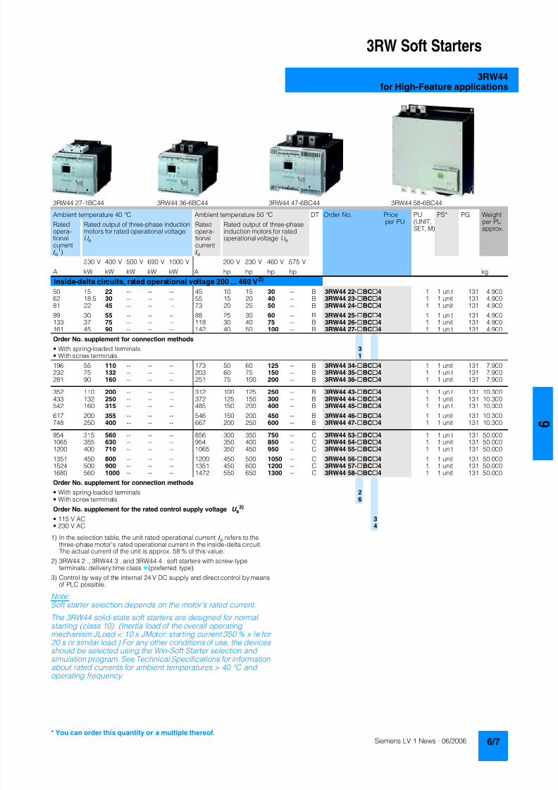
8122019 Arr Estado Solido
httpslidepdfcomreaderfullarr-estado-solido 1140
3RW Soft Starters
3RW44for High-Feature applications
1) In the selection table the unit rated operational current I e refers to the
three-phase motors rated operational current in the inside-delta circuitThe actual current of the unit is approx 58 of this value
2) 3RW44 2 3RW44 3 and 3RW44 4 soft starters with screw-typeterminals delivery time class (preferred type)
3) Control by way of the internal 24 V DC supply and direct control by meansof PLC possible
NoteSoft starter selection depends on the motors rated current
The 3RW44 solid-state soft starters are designed for normalstarting (class 10) (Inertia load of the overall operatingmechanism JLoad lt 10 x JMotor starting current 350 x Ie for20 s or similar load) For any other conditions of use the devicesshould be selected using the Win-Soft Starter selection andsimulation program See Technical Specifications for informationabout rated currents for ambient temperatures gt 40 degC andoperating frequency
3RW44 27-1BC44 3RW44 36-6BC44 3RW44 47-6BC44 3RW44 58-6BC44
Ambient temperature 40 degC Ambient temperature 50 degC DT Order No Priceper PU
PU(UNITSET M)
PS PG Weightper PUapprox
Ratedopera-tionalcurrent I e
1)
Rated output of three-phase inductionmotors for rated operational voltageU e
Ratedopera-tionalcurrent I e
Rated output of three-phaseinduction motors for ratedoperational voltage U e
230 V 400 V 500 V 690 V 1000 V 200 V 230 V 460 V 575 V
A kW kW kW kW kW A hp hp hp hp kgInside-delta circuits rated operational voltage 200 460 V2)
50 15 22 -- -- -- 45 10 15 30 -- B 3RW44 22-BC4 1 1 unit 131 490062 185 30 -- -- -- 55 15 20 40 -- B 3RW44 23-BC4 1 1 unit 131 490081 22 45 -- -- -- 73 20 25 50 -- B 3RW44 24-BC4 1 1 unit 131 4900
99 30 55 -- -- -- 88 25 30 60 -- B 3RW44 25-BC4 1 1 unit 131 4900133 37 75 -- -- -- 118 30 40 75 -- B 3RW44 26-BC4 1 1 unit 131 4900161 45 90 -- -- -- 142 40 50 100 -- B 3RW44 27-BC4 1 1 unit 131 4900
Order No supplement for connection methods
bull With spring-loaded terminals 3bull With screw terminals 1
196 55 110 -- -- -- 173 50 60 125 -- B 3RW44 34-BC4 1 1 unit 131 7900232 75 132 -- -- -- 203 60 75 150 -- B 3RW44 35-BC4 1 1 unit 131 7900281 90 160 -- -- -- 251 75 100 200 -- B 3RW44 36-BC4 1 1 unit 131 7900
352 110 200 -- -- -- 312 100 125 250 -- B 3RW44 43-BC4 1 1 unit 131 10300433 132 250 -- -- -- 372 125 150 300 -- B 3RW44 44-BC4 1 1 unit 131 10300542 160 315 -- -- -- 485 150 200 400 -- B 3RW44 45-BC4 1 1 unit 131 10300
617 200 355 -- -- -- 546 150 200 450 -- B 3RW44 46-BC4 1 1 unit 131 10300748 250 400 -- -- -- 667 200 250 600 -- B 3RW44 47-BC4 1 1 unit 131 10300
954 315 560 -- -- -- 856 300 350 750 -- C 3RW44 53-BC4 1 1 unit 131 500001065 355 630 -- -- -- 954 350 400 850 -- C 3RW44 54-BC4 1 1 unit 131 500001200 400 710 -- -- -- 1065 350 450 950 -- C 3RW44 55-BC4 1 1 unit 131 50000
1351 450 800 -- -- -- 1200 450 500 1050 -- C 3RW44 56-BC4 1 1 unit 131 500001524 500 900 -- -- -- 1351 450 600 1200 -- C 3RW44 57-BC4 1 1 unit 131 500001680 560 1000 -- -- -- 1472 550 650 1300 -- C 3RW44 58-BC4 1 1 unit 131 50000
Order No supplement for connection methods
bull With spring-loaded terminals 2bull With screw terminals 6
Order No supplement for the rated control supply voltage U s3)
bull 115 V AC 3bull 230 V AC 4
You can order this quantity or a multiple thereof
8122019 Arr Estado Solido
httpslidepdfcomreaderfullarr-estado-solido 1240
3RW Soft Starters
3RW44for High-Feature applications
1) In the selection table the unit rated operational current I e refers to thethree-phase motors rated operational current in the inside-delta circuitThe actual current of the unit is approx 58 of this value
2) 3RW44 2 3RW44 3 and 3RW44 4 soft starters with screw-typeterminals delivery time class A
3) Control by way of the internal 24 V DC supply and direct control by meansof PLC possible
Accessories
NoteSoft starter selection depends on the motors rated current
The 3RW44 solid-state soft starters are designed for normalstarting (class 10) (Inertia load of the overall operatingmechanism J Load lt 10 x J Motor starting current 350 x I e for20 s or similar load) For any other conditions of use the devicesshould be selected using the Win-Soft Starter selection andsimulation program See Technical Specifications for informationabout rated currents for ambient temperatures gt 40 degC andoperating frequency
Ambient temperature 40 degC Ambient temperature 50 degC DT Order No Priceper PU
PU(UNITSET M)
PS PG Weightper PUapprox
Ratedopera-
tionalcurrent I e
1)
Rated output of three-phaseinduction motors for rated opera-
tional voltage U e
Ratedopera-
tionalcurrent I e
Rated output of three-phaseinduction motors for rated
operational voltage U e
230 V 400 V 500 V 690 V 1000 V 200 V 230 V 460 V 575 V
A kW kW kW kW kW A hp hp hp hp kg
Inside-delta circuits rated operational voltage 400 600 V2)
50 -- 22 30 -- -- 45 -- -- 30 40 B 3RW44 22-BC5 1 1 unit 131 490062 -- 30 37 -- -- 55 -- -- 40 50 B 3RW44 23-BC5 1 1 unit 131 490081 -- 45 45 -- -- 73 -- -- 50 60 B 3RW44 24-BC5 1 1 unit 131 4900
99 -- 55 55 -- -- 88 -- -- 60 75 B 3RW44 25-BC5 1 1 unit 131 4900133 -- 75 90 -- -- 118 -- -- 75 100 B 3RW44 26-BC5 1 1 unit 131 4900161 -- 90 110 -- -- 142 -- -- 100 125 B 3RW44 27-BC5 1 1 unit 131 4900
Order No supplement for connection methods
bull With spring-loaded terminals 3bull With screw terminals 1
196 -- 110 132 -- -- 173 -- -- 125 150 B 3RW44 34-BC5 1 1 unit 131 7900232 -- 132 160 -- -- 203 -- -- 150 200 B 3RW44 35-BC5 1 1 unit 131 7900
281 -- 160 200 -- -- 251 -- -- 200 250 B 3RW44 36-BC5 1 1 unit 131 7900
352 -- 200 250 -- -- 312 -- -- 250 300 B 3RW44 43-BC5 1 1 unit 131 10300433 -- 250 315 -- -- 372 -- -- 300 350 B 3RW44 44-BC5 1 1 unit 131 10300542 -- 315 355 -- -- 485 -- -- 400 500 B 3RW44 45-BC5 1 1 unit 131 10300
617 -- 355 450 -- -- 546 -- -- 450 600 B 3RW44 46-BC5 1 1 unit 131 10300748 -- 400 500 -- -- 667 -- -- 600 750 B 3RW44 47-BC5 1 1 unit 131 10300
954 -- 560 630 -- -- 856 -- -- 750 950 C 3RW44 53-BC5 1 1 unit 131 500001065 -- 630 710 -- -- 954 -- -- 850 1050 C 3RW44 54-BC5 1 1 unit 131 500001200 -- 710 800 -- -- 1065 -- -- 950 1200 C 3RW44 55-BC5 1 1 unit 131 50000
1351 -- 800 900 -- -- 1200 -- -- 1050 1350 C 3RW44 56-BC5 1 1 unit 131 500001524 -- 900 1000 -- -- 1351 -- -- 1200 1500 C 3RW44 57-BC5 1 1 unit 131 500001680 -- 1000 1200 -- -- 1472 -- -- 1300 1650 C 3RW44 58-BC5 1 1 unit 131 50000
Order No supplement for connection methods
bull With spring-loaded terminals 2bull With screw terminals 6
Order No supplement for the rated control supply voltage U s3)
bull 115 V AC 3bull 230 V AC 4
Forsoft starters Version DT Order No Priceper PU PU(UNITSET M)
PS PG Weightper PUapprox
Type kg
Soft Starter ES 2006 PC communication program
Soft Starter ES 2006 Smart
Parameterization and service software forSIRIUS 3RW44 soft starters for parameterizingthrough the system interface on the deviceExecutes on PCPG under Windows 2000XPwithout PC cableType of supply CD single license
3ZS1 313-1CC10-0YA0 1 1 unit 131 0230
3ZS1 313-1CC10-0YA0 Soft Starter ES 2006 Professional
Parameterization and service software forSIRIUS 3RW44 soft starters for parameterizingthrough the system interface on the device andPROFIBUS DP interface (PROFIBUS as optional commu-nication module necessary)Executes on PCPG under Windows 2000XPwithout PC cableType of supply CD single license
A 3ZS1 313-2CC10-0YA0 1 1 unit 131 0230
8122019 Arr Estado Solido
httpslidepdfcomreaderfullarr-estado-solido 1340
3RW Soft Starters
3RW44for High-Feature applications
Spare parts
Forsoft starters
Version DT Order No Priceper PU
PU(UNITSET M)
PS PG Weightper PUapprox
Type kg
PC cables
For PCPG communication with SIRIUS 3RW44soft starters
through the system interface for connecting tothe serial interface of the PCPG
B 3UF7 940-0AA00-0 1 1 unit 131 0150
Box terminal blocks for soft starters
Box terminal blocks
3RW44 2 Included in del ivery
3RW44 3 bull Up to 70 mm2 3RT19 55-4G 1 1 unit 101 0237
bull Up to 120 mm2 3RT19 56-4G 1 1 unit 101 0270
3RW44 3 bull Up to 240 mm2 3RT19 66-4G 1 1 unit 101 0676
PROFIBUS Communication moduleModule to be plugged into the soft starter to connect thesoft starter to the PROFIBUS net
A 3RW4 900-0KC00 1 1 unit 131 0320
External display and operation module
to show and operate the fonctions supplied by the softstarter via externally mounted display and operationmodule(for example in the cubicle door)
A 3RW4 900-0AC00 1 1 unit 131 0320
Connection cable
from serial interface of 3RW44 soft starter to external dis-play and operation modulebull Length 05 m flat B 3UF7 932-0AA00-0 1 1 unit 131 0020bull Length 05 m round A 3UF7 932-0BA00-0 1 1 unit 131 0050bull Length10 m round A 3UF7 937-0BA00-0 1 1 unit 131 0100bull Length25 m round A 3UF7 933-0BA00-0 1 1 unit 131 0150
Covers for soft starters
Terminal covers for box terminals
Additional touch protection to be fitted at the boxterminals (2 units required per device)
3RW44 2 and3RW44 3
3RT19 56-4EA2 1 1 unit 101 0028
3RW44 4 3RT19 66-4EA2 1 1 unit 101 0038
Terminal covers for cable lugs and busbarconnections
3RW44 2 and3RW44 3
3RT19 56-4EA1 1 1 unit 101 0067
3RW44 4 3RT19 66-4EA1 1 1 unit 101 0124
Forsoft starters
Version DT Order No Priceper PU
PU(UNITSET M)
PS PG Weightper PUapprox
Type kg
Fans
Fans
3RW44 2 and3RW44 3
115 VAC 3RW49 36-8VX30 1 1 unit 131 0300230 VAC 3RW49 36-8VX40 1 1 unit 131 0300
3RW44 4 115 V AC 3RW49 47-8VX30 1 1 unit 131 0500230 VAC 3RW49 47-8VX40 1 1 unit 131 0500
3RW44 5 115 V AC 3RW49 57-8VX30 1 1 unit 131 0800230 VAC 3RW49 57-8VX40 1 1 unit 131 0800
You can order this quantity or a multiple thereof
8122019 Arr Estado Solido
httpslidepdfcomreaderfullarr-estado-solido 1440
3RW Soft Starters
3RW44for High-Feature applications
Function
Equipped with modern ergonomic user prompting theSIRIUS 3RW44 soft starters can be commissioned quickly and
easily using a keypad and a menu-prompted multi-line displaywith background lighting Motor starting and deceleration areoptimized quickly easily and safely with just a few settings in aselectable language Four-key operation and plain-text displaysfor each menu point guarantee full clarity at every moment of theparameterization and operation Measurement values and oper-ating values as well as warning messages and fault indicationsare output continuously on the front panel during operation andwhen control voltage is applied An external display and opera-tor module can be connected by means of a connecting cableto the soft starter thus enabling active indications and the like tobe read directly from the control cabinet door
The SIRIUS 3RW44 soft starters are equipped with optimumfunctionality An integral bypass contact system reduces thepower loss of the soft starter during operation This reliablyprevents heating of the switchgear environment TheSIRIUS 3RW44 soft starters have internal intrinsic deviceprotection This prevents thermal overloading of the powersections thyristors eg due to unacceptably high closingoperations
Wiring work for installing an additional motor overload relay is nolonger needed as the SIRIUS 3RW44 soft starters perform thisfunction too In addition they offer adjustable trip classes and athermistor motor protection function As an option the thyristorscan also be protected by SITOR semi-conductor fuses fromshort-circuiting And even inrush current peaks are reliablyavoided thanks to adjustable current limiting
As a further option the SIRIUS 3RW44 soft starters can beupgraded with a PROFIBUS DP module Thanks to their commu-nication capability and their programmable control inputs andrelay outputs the SIRIUS 3RW44 soft starters can be very easily
and quickly integrated in higher-level controllersIn addition a creep speed function is available for positioningand setting jobs With this function the motor can be controlledin both directions of rotation with reduced torque and an adjust-able low speed
On the other hand the SIRIUS 3RW44 soft starters offer a newcombined DC braking function for the fast stopping of drivingloads
Highlights bull Soft starting with breakaway pulse torque control or voltage
ramp and adjustable torque or current limiting as well as anycombination of these depending on load type
bull Integrated bypass contact system to minimize dissipatedpower
bull Various setting options for the starting parameters such asstarting torque starting voltage ramp-up and ramp-downtime and much more in three separate parameter sets
bull Start-up detectionbull Inside-delta circuit for savings in terms of size and equipment
costsbull Various ramp-down modes selectable free ramp-down
torque-controlled pump stopping combined DC brakingbull Solid-state motor overload and intrinsic device protectionbull Thermistor motor protectionbull Keypad with a menu-controlled multi-line graphic display with
background lighting
bull Interface for communication with the PC for more accuratesetting of the parameters as well as for control and monitoringbull Simple adaptation to the motor feederbull Simple mounting and commissioningbull Display of operating states and fault signalsbull Connection to PROFIBUS with optional PROFIBUS DP modulebull External display and operator modulebull System voltages from 200 to 690 V 50 to 60 Hzbull Applicable up to 60 degC (derating from 40 degC)
8122019 Arr Estado Solido
httpslidepdfcomreaderfullarr-estado-solido 1540
3RW Soft Starters
3RW44for High-Feature applications
Technical specifications
Type 3RW44 -BC3 3RW44 -BC4Terminal
Control electronics
Rated valuesRated control supply voltage A1A2PE V 115 AC 230 ACbull Tolerance -15+10 -15+10Rated control supply current STANDBY mA 30 20
Rated control supply current ONbull 3RW44 2 mA 300 170bull 3RW44 3 mA 500 250bull 3RW44 4 mA 750 400bull 3RW44 5 mA 450 200
Maximum current (pickup bypass)bull 3RW44 2 mA 1000 500bull 3RW44 3 mA 2500 1250bull 3RW44 4 mA 6000 3000bull 3RW44 5 mA 4500 2500
Rated frequency Hz 50 60 50 60bull Tolerance plusmn10 plusmn10
Type 3RW44 Terminal Factory presetting
Control electronics
Control inputsInput 1 IN1 Start motor right parameter set 1Input 2 IN2 No actionInput 3 IN3 No actionInput 4 IN4 Trip reset
Supply L+L-bull Rated operational current mA Approx 10 per input to DIN 19240bull Rated operational voltage L+ Internal voltage 24 V DC from inter-
nal supply through terminal L+ toIN1 IN4 Maximum load at L+approx 55 mA
L- External voltage DC external voltage(to DIN19240) through terminals
L- and IN1 IN4(min 12 V DC max 30 V DC)
Thermistor motor protection inputInput T1T2 PTC type A or Thermoclick Deactivated
Relay outputs (floating auxiliary contacts)Output 1 1314 ON periodOutput 2 2324 No actionOutput 3 3334 No actionOutput 4 959698 Group fault
Switching capacity of the relay outputs230 VAC-15 A 3 at 240 V24 VDC-13 A 1 at 24 VProtection against overvoltages Protection by means of Varistor through relay contactShort-circuit protection 4 A gLgG operational class
6 A quick (fuse is not included in scope of supply)
Protective functions
Motor protection functionsTrips in the event of Thermal overloading of the motor
Trip class to IEC 60947-4-1 Class 510152030 10Phase failure sensitivity gt 40
Overload warning yesReset and recovery ManualAutomatic ManualReset option after tripping ManualAutomatic ManualRecovery time min 1 30 1
Device protection functionsTrips in the event of Thermal overloading of the thyristorsReset option after tripping ManualAutomatic ManualRecovery time min 05
8122019 Arr Estado Solido
httpslidepdfcomreaderfullarr-estado-solido 1640
3RW Soft Starters
3RW44for High-Feature applications
Type 3RW44 Factory presetting
Control times and parameters
Control timesClosing delay (with connected control voltage) ms lt 50Closing delay (automatic mode) ms lt 4000Recovery time (closing command in active ramp-down) ms lt 100
Mains failure bridging timeControl supply voltage ms 100
Mains failure response timeLoad current circuit ms 100
Reclosing lockout after overload tripMotor protection trip min 1 30 1Device protection trip s 30
Setting options for startingVoltage ramp for starting voltage 20 100 30Torque control for starting torque 20 100 50Torque control for limit torque 20 200 150
Starting time s 0 360 20Maximum starting time s 1 1000 DeactivatedCurrent limit value 125 550 450
Breakaway voltage 40 100 80Breakaway time s 0 2 DeactivatedMotor heat output 0 100 0
Creep mode LeftRight runningSpeed factor as function of rated speed (n = n rated factor) 3 21 7Creep torque (reference variable depends on the motor used but isalways smaller than the rated torque of the motor)
20 100 50
Setting options for ramp-downTorque control for stopping torque 10 100 10Ramp-down time s 0 360 10Dynamic braking torque 20 100 50DC braking torque 20 100 50
Operating indicationsTest voltageTest mains phasesReady to start
Start active
Motor runningRamp-down active
Warningserror signalsMains voltage missingLeading-edge phase error
Phase failurebull L1bull L2bull L3
Missing load phasebull T1bull T2bull T3
Failurebull Contact element 1 (thyristor)bull Contact element 2 (thyristor)bull Contact element 3 (thyristor)
Flash memory faulty
Supply voltagebull Below 75 bull Below 85 bull Over 110
Current unbalance exceededThermal motor model overload
Prewarning limit exceededbull Motor heatingbull Time-related trip reserve
Bypass elements defectiveMains voltage too high
Device not namedWrong naming versionCurrent range exceeded
Motor blocking ndash shutdownCurrent limit exceeded
Power section
bull Overheatedbull OvertemperatureEmergency active
8122019 Arr Estado Solido
httpslidepdfcomreaderfullarr-estado-solido 1740
3RW Soft Starters
3RW44for High-Feature applications
1) Parameter motor left possible only in conjunction with creep mode
Type 3RW44 Factory presetting
Control times and parameters
Warningserror signals (contd)Temperature sensorbull Overloadbull Open-circuitbull Short-circuit
Ground faultbull Detectedbull Shutdown
Connection abort in manual modeMax number of starts exceeded I e limit value overshootundershoot
Cooling timebull Motor activebull Switch block active
Heat sink sensorbull Open-circuitbull Short-circuit
Quick-stop functionSwitch block faulty I e class setting not permissible
Control inputsInput 1 Motor right parameter set 1Input 2 No actionInput 3 No actionInput 4 Trip reset
Parameterizing options for control inputs 1 4 No actionLocal manual modeEmergency startCreep speedQuick-stopTrip reset
Motor right parameter set 1Motor left parameter set 11) Motor right parameter set 2Motor left parameter set 21) Motor right parameter set 3Motor left parameter set 31)
Relay outputsOutput 1 ON periodOutput 2 No actionOutput 3 No actionOutput 4 Group fault
Parameterizing options for relay outputs 1 3 No actionPAA output 1PAA output 2
Input 1Input 2Input 3Input 4
Ramp-upOperationBypassRamp-downON periodCommand motor on
FanDC braking contactor
Group warningGroup faultBus faultDevice error
Power onReady to start
Motor temperature sensors Deactivated DeactivatedThermoclickPTC type A
8122019 Arr Estado Solido
httpslidepdfcomreaderfullarr-estado-solido 1840
3RW Soft Starters
3RW44for High-Feature applications
1) Current limit on soft starter set to 350 I M
2) For intermittent duty S4 with ON period = 70 T u = 40 degC stand-aloneinstallation vertical The quoted operating frequencies do not apply forautomatic mode
3) Maximum adjustable rated motor current I M dependent on CLASS setting
Type 3RW44 -BC4 3RW44 -BC5 3RW44 -BC6
Power electronics
Rated operational voltage for inline circuit V 200 460 AC 400 600 AC 400 690 AC
Tolerance -15+10 -15+10 -15+10Rated operational voltage for inside-delta circuit V 200 460 AC 400 600 AC 400 600 ACTolerance -15+10 -15+10 -15+10
Rated frequency Hz 50 60Tolerance plusmn10
Continuous operation at 40 degC ( of I e) 115
Minimum load ( of set motor current I M) 8
Maximum conductor length between soft starter and motor m 200
Permissible installation height m 5000 (derating from 1000 see characteristics) higher on request
Permissible mounting position
Permissible ambient temperatureOperation degC 0 +60 (derating from +40)Storage degC -25 +80
Degree of protection IP00
Type 3RW44 22 3RW44 23 3RW44 24 3RW44 25 3RW44 26 3RW44 27
Power electronics
Rated operational current I e 29 36 47 57 77 93
Load rating with rated operational current I ebull Acc to IEC and ULCSA for individual mounting
at 405060 degC AC-53a A 292623 363229 474237 575145 776859 938272
Smallest adjustable rated motor current I Mfor the motor overload protection
A 5 7 9 11 15 18
Power lossbull In operation after completed ramp-up with uninterrupted rated
operational current (40 degC) approx W 8 10 32 36 45 55bull During starting with current limit set to 350 I M (40 degC) W 400 470 600 725 940 1160
Permissible rated motor current and starts per hour
bull Normal starting (Class 5)- Rated motor current I M
1) starting time 5 s A 29 36 47 57 77 93- Starts per hour2) 1h 41 34 41 41 41 41
- Rated motor current I M1)3) starting time 10 s A 29 36 47 57 77 93
- Starts per hour2) 1h 20 15 20 20 20 20
bull Normal starting (Class 10)- Rated motor current I M
1) starting time 10 s A 29 36 47 57 77 93- Starts per hour2) 1h 20 15 20 20 20 20
- Rated motor current I M1)3) starting time 20 s A 29 36 47 57 77 93
- Starts per hour2) 1h 10 6 10 10 8 8
bull Normal starting (Class 15)- Rated motor current I M
1) starting time 15 s A 29 36 47 57 77 93- Starts per hour2) 1h 13 9 13 13 13 13
- Rated motor current I M1)3) starting time 30 s A 29 36 47 57 77 93
- Starts per hour2) 1h 6 4 6 6 6 6
bull For heavy starting (Class 20)- Rated motor current I M
1) starting time 20 s A 29 36 47 57 73 88- Starts per hour2) 1h 10 6 10 10 10 10
- Rated motor current I M1)3) starting time 40 s A 29 36 47 57 73 88
- Starts per hour2) 1h 4 2 4 5 18 08
bull For very heavy starting (Class 30)- Rated motor current I M
1) starting time 30 s A 29 36 44 57 65 77- Starts per hour2) 1h 6 4 6 6 6 6
- Rated motor current I M1)3) starting time 60 s A 29 36 44 57 65 77
- Starts per hour2) 1h 18 08 33 15 2 1
8122019 Arr Estado Solido
httpslidepdfcomreaderfullarr-estado-solido 1940
3RW Soft Starters
3RW44for High-Feature applications
1) Current limit on soft starter set to 350 I M
2) For intermittent duty S4 with ON period = 70 T u = 40 degC stand-aloneinstallation vertical The quoted operating frequencies do not apply forautomatic mode
3) Maximum adjustable rated motor current I M dependent on CLASS setting
Type 3RW44 34 3RW44 35 3RW44 36
Power electronics
Rated operational current I e 113 134 162
Load rating with rated operational current I ebull Acc to IEC and ULCSA for individual mounting AC-53a
- at 40 degC A 113 134 162- at 50 degC A 100 117 145- at 60 degC A 88 100 125
Smallest adjustable rated motor current I Mfor the motor overload protection
A 22 26 32
Power lossbull In operation after completed ramp-up with uninterrupted rated
operational current (40 degC) approx W 64 76 95bull During starting with current limit set to 350 I M (40 degC) W 1350 1700 2460
Permissible rated motor current and starts per hour
bull Normal starting (Class 5)- Rated motor current I M
1) starting time 5 s A 113 134 162- Starts per hour2) 1h 41 39 41
- Rated motor current I M1)3) starting time 10 s A 113 134 162
- Starts per hour2) 1h 20 15 20
bull Normal starting (Class 10)- Rated motor current I M
1) starting time 10 s A 113 134 162- Starts per hour2) 1h 20 15 20
- Rated motor current I M1)3) starting time 20 s A 113 134 162
- Starts per hour2) 1h 9 6 7
bull Normal starting (Class 15)- Rated motor current I M
1) starting time 15 s A 113 134 162- Starts per hour2) 1h 13 9 12
- Rated motor current I M1)3) starting time 30 s A 113 134 162
- Starts per hour2) 1h 6 6 1
bull For heavy starting (Class 20)- Rated motor current I M
1) starting time 20 s A 106 125 147- Starts per hour2) 1h 9 9 10
- Rated motor current I M1)3) starting time 40 s A 106 125 147
- Starts per hour2) 1h 15 2 1
bull For very heavy starting (Class 30)- Rated motor current I M
1) starting time 30 s A 91 110 120
- Starts per hour2) 1h 6 6 6- Rated motor current I M
1)3) starting time 60 s A 91 110 120- Starts per hour2) 1h 2 2 2
8122019 Arr Estado Solido
httpslidepdfcomreaderfullarr-estado-solido 2040
3RW Soft Starters
3RW44for High-Feature applications
1) Current limit on soft starter set to 350 I M
2) For intermittent duty S4 with ON period = 70 T u = 40 degC stand-aloneinstallation vertical The quoted operating frequencies do not apply forautomatic mode
3) Maximum adjustable rated motor current I M dependent on CLASS setting
Type 3RW44 43 3RW44 44 3RW44 45 3RW44 46 3RW44 47
Power electronics
Rated operational current I e 203 250 313 356 432
Load rating with rated operational current I ebull Acc to IEC and ULCSA for individual mounting AC-53a
- at 40 degC A 203 250 313 356 432- at 50 degC A 180 215 280 315 385- at 60 degC A 156 185 250 280 335
Smallest adjustable rated motor current I Mfor the motor overload protection
A 40 50 62 71 86
Power lossbull In operation after completed ramp-up with uninterrupted rated
operational current (40 degC) approx W 89 110 145 174 232bull During starting with current limit set to 350 I M (40 degC) W 3350 4000 4470 5350 5860
Permissible rated motor current and starts per hour
bull Normal starting (Class 5)- Rated motor current I M
1) starting time 5 s A 203 250 313 356 432- Starts per hour2) 1h 41 41 41 41 39
- Rated motor current I M1)3) starting time 10 s A 203 250 313 356 432
- Starts per hour2) 1h 20 20 19 17 16
bull Normal starting (Class 10)- Rated motor current I M
1) starting time 10 s A 203 250 313 356 432- Starts per hour2) 1h 20 20 19 17 16
- Rated motor current I M1)3) starting time 20 s A 203 250 313 356 432
- Starts per hour2) 1h 9 10 6 4 5
bull Normal starting (Class 15)- Rated motor current I M
1) starting time 15 s A 203 240 313 325 402- Starts per hour2) 1h 13 13 10 13 11
- Rated motor current I M1)3) starting time 30 s A 203 240 313 325 402
- Starts per hour2) 1h 3 6 1 2 1
bull For heavy starting (Class 20)- Rated motor current I M
1) starting time 20 s A 195 215 275 285 356- Starts per hour2) 1h 10 10 10 10 10
- Rated motor current I M1)3) starting time 40 s A 195 215 275 285 356
- Starts per hour2) 1h 1 5 1 3 1
bull For very heavy starting (Class 30)- Rated motor current I M
1) starting time 30 s A 162 180 220 240 285
- Starts per hour2) 1h 6 6 6 6 6- Rated motor current I M
1)3) starting time 60 s A 162 180 220 240 285- Starts per hour2) 1h 3 3 3 2 1
8122019 Arr Estado Solido
httpslidepdfcomreaderfullarr-estado-solido 2140
3RW Soft Starters
3RW44for High-Feature applications
1) Current limit on soft starter set to 350 I M
2) For intermittent duty S4 with ON period = 70 T u = 40 degC stand-aloneinstallation vertical The quoted operating frequencies do not apply forautomatic mode
3) Maximum adjustable rated motor current I M dependent on CLASS setting
Type 3RW44 53 3RW44 54 3RW44 55 3RW44 56 3RW44 57 3RW44 58
Power electronics
Rated operational current I e 551 615 693 780 880 970
Load rating with rated operational current I ebull Acc to IEC and ULCSA for individual mounting AC-53a
- at 40 degC A 551 615 693 780 880 970- at 50 degC A 494 551 615 693 780 850- at 60 degC A 438 489 551 615 693 760
Smallest adjustable rated motor current I Mfor the motor overload protection
A 110 123 138 156 176 194
Power lossbull In operation after completed ramp-up with uninterrupted rated
operational current (40 degC) approx W 159 186 220 214 250 270bull During starting with current limit set to 350 I M (40 degC) W 7020 8100 9500 11100 13100 15000
Permissible rated motor current and starts per hour
bull Normal starting (Class 5)- Rated motor current I M
1) starting time 5 s A 551 615 693 780 880 970- Starts per hour2) 1h 41 41 37 33 22 17
- Rated motor current I M1)3) starting time 10 s A 551 615 693 780 880 970
- Starts per hour2) 1h 20 20 16 13 8 5
bull Normal starting (Class 10)- Rated motor current I M
1) starting time 10 s A 551 615 693 780 880 970- Starts per hour2) 1h 20 20 16 13 8 5
- Rated motor current I M1)3) starting time 20 s A 551 615 693 780 880 970
- Starts per hour2) 1h 10 9 6 4 03 03
bull Normal starting (Class 15)- Rated motor current I M
1) starting time 15 s A 551 615 666 723 780 821- Starts per hour2) 1h 13 13 11 9 8 8
- Rated motor current I M1)3) starting time 30 s A 551 615 666 723 780 821
- Starts per hour2) 1h 6 4 3 1 04 05
bull For heavy starting (Class 20)- Rated motor current I M
1) starting time 20 s A 551 591 633 670 710 740- Starts per hour2) 1h 10 10 7 8 8 9
- Rated motor current I M1)3) starting time 40 s A 551 591 633 670 710 740
- Starts per hour2) 1h 4 2 1 1 04 1
bull For very heavy starting (Class 30)- Rated motor current I M
1) starting time 30 s A 500 525 551 575 600 630
- Starts per hour2) 1h 6 6 6 6 6 6- Rated motor current I M
1)3) starting time 60 s A 500 525 551 575 600 630- Starts per hour2) 1h 2 1 1 1 15 1
8122019 Arr Estado Solido
httpslidepdfcomreaderfullarr-estado-solido 2240
3RW Soft Starters
3RW44for High-Feature applications
1) When connecting cable lugs to DIN 46235 use 3RT19 56-4EA1 terminalcover for conductor cross-sections from 95 mmsup2 to ensure phase spacing
2) When connecting cable lugs to DIN 46234 the 3RT19 66-4EA1 terminalcover must be used for conductor cross-sections of 240 mmsup2 and more aswell as DIN 46235 for conductor cross-sections of 185 mmsup2 and more tokeep the phase clearance
Type 3RW44 2 3RW44 3 3RW44 4 3RW44 5
Conductor cross-sections
Screw
terminals
Main conductors
with box terminal 3RT19 55-4G (55 kW) 3RT19 66-4G
Front clampingpoint connected
bull Finely stranded with end sleeve mm2 16 70 70 240bull Finely stranded without end sleeve mm2 16 70 70 240bull Stranded mm2 16 70 95 300
bull Ribbon cable conductors(number x width x thickness)
mm min 3 x 9 x 08max 6 x 155 x 08
min 6 x 9 x 08max 20 x 24 x 05
bull AWG conductors solid or stranded AWG 6 20 30 600 kcmil
Rear clamping pointconnected
bull Finely stranded with end sleeve mm2 16 70 120 185bull Finely stranded without end sleeve mm2 16 70 120 185bull Stranded mm2 16 70 120 240
bull Ribbon cable conductors(number x width x thickness)
mm min 3 x 9 x 08max 6 x 155 x 08
min 6 x 9 x 08max 20 x 24 x 05
bull AWG conductors solid or stranded AWG 6 20 250 500 kcmil
Both clamping
points connected
bull Finely stranded with end sleeve mm2 max 1 x 50 1 x 70 min 2 x 50 max 2 x 185
bull Finely stranded without end sleeve mm2 max 1 x 50 1 x 70 min 2 x 50 max 2 x 185bull Stranded mm2 max 2 x 70 max 2 x 70 max 2 x 240
bull Ribbon cable conductors(number x width x thickness)
mm max 2 x (6 x 155 x 08) max 2 x (20 x 24 x 05)
bull AWG conductors solid or stranded AWG max 2 x 10 min 2 x 20max 2 x 500 kcmil
bull Terminal screws M10 (hexagon socket AF4) M12 (hexagon socket AF5)- Pickup torque 10 12 20 22
90 110 180 195
Screwterminals
Main conductors
with box terminal 3RT19 56-4G
Front or rear clamp-ing point connected
bull Finely stranded with end sleeve mm2 16 120bull Finely stranded without end sleeve mm2 16 120bull Stranded mm2 16 120
bull Ribbon cable conductors(number x width x thickness)
mm min 3 x 9 x 08max 6 x 155 x 08
bull AWG conductors solid or stranded AWG 6 250 kcmil
Both clampingpoints connected
bull Finely stranded with end sleeve mm2 max 1 x 95 1 x 120bull Finely stranded without end sleeve mm2 max 1 x 95 1 x 120bull Stranded mm2 max 2 x 120
bull Ribbon cable conductors(number x width x thickness)
mm max 2 x (10 x 155 x 08)
bull AWG conductors solid or stranded AWG max 2 x 30
Screwterminals
Main conductors
Without box terminalrail connection
bull Finely stranded with cable lug mm2 16 951) 50 2402) 50 2402)
bull Stranded with cable lug mm2 25 1201) 70 2402) 70 2402)
bull AWG conductors solid or stranded AWG 4 250 kcmil 20 500 kcmil 10 500 kcmil
bull Connecting bar (max width) mm 17 25 60
bull Terminal screws M8 x 25 (AF13) M10 x 30 (AF17) M12 x 40- Pickup torque NM 10 14 14 24 20 35lbin 89 124 124 210 177 310
8122019 Arr Estado Solido
httpslidepdfcomreaderfullarr-estado-solido 2340
3RW Soft Starters
3RW44for High-Feature applications
Soft starters Type 3RW44
Conductor cross-sections
Auxiliary conductors (1 or 2 conductors can be connected)
Screw terminals
bull Solid mm2 2 x 05 25bull Finely stranded with end sleeve mm2 2 x 05 15
bull AWG cables- Solid or stranded AWG 2 x 20 14- Finely stranded with end sleeve AWG 2 x 20 16
bull Terminal screws- Pickup torque NM 07 09
lbin 7 8
Spring-loaded terminals
bull Solid mm2 2 x 025 25bull Finely stranded with end sleeve mm2 2 x 025 15bull AWG conductors solid or stranded AWG 2 x 24 14
Standard Parameters
Electromagnetic compatibility acc to EN 60947-4-2
EMC interference immunityElectrostatic discharge (ESD) EN 61000-4-2 plusmn4 kV contact discharge plusmn8 kV air discharge
Electromagnetic RF fields EN 61000-4-3 Frequency range 80 1000 MHz with 80 at 1 kHzDegree of severity 3 10 Vm
Conducted RF interference EN 61000-4-6 Frequency range 150 kHz 80 MHz with 80 at 1 kHzInterference 10 V
RF voltages and RF currents on conductorsBurst EN 61000-4-4 plusmn2 kV5 kHzSurge EN 61000-4-5 plusmn1 kV line to line
plusmn2 kV line to ground
EMC interference emission
EMC interference field strength EN55011 Limit value of Class A at 30 1000 MHz
Radio interference voltage EN55011 Limit value of Class A at 015 30 MHz
Is an RI suppression filter necessary
Degree of noise suppression A (industrial applications) no
8122019 Arr Estado Solido
httpslidepdfcomreaderfullarr-estado-solido 2440
3RW Soft Starters
3RW44for High-Feature applications
Fuse assignment
The coordination type to which the motor feeder with soft starteris mounted depends on the application-specific requirements
Normally fuseless mounting (combination of motor starter pro-tector and soft starter) is sufficient If type 2 coordination is to befulfilled semiconductor fuses must be fitted in the motor feeder
1) The rated motor current must be considered when selecting the devices
2) The types of coordination are explained in more detail in theTechnical information LV 1 T under ndash Fuseless Load Feeders
Inline circuit fuseless version
Soft starters Motor starter protectorscircuit-breakers1)
Rated current 440 V +10 Rated currentG1 Q1Type A Type A
Type of coordination 12) 3RW44 22 3RW44 27 I q = 32 kA 3RW44 34 and 3RW44 35 I q = 16 kA 3RW44 36 3RW44 57 I q = 65 kA
3RW44 22 29 3RV10 42-4HA10 503RW44 23 36 3RV10 42-4JA10 633RW44 24 47 3RV10 42-4KA10 75
3RW44 25 57 3RV10 42-4LA10 903RW44 26 77 3RV10 42-4MA10 1003RW44 27 93 3RV10 42-4MA10 100
3RW44 34 113 3VL17 16-2DD36 1603RW44 35 134 3VL17 16-2DD36 1603RW44 36 162 3VL37 25-2DC36 250
3RW44 43 203 3VL47 31-3DC36 3153RW44 44 250 3VL47 31-3DC36 3153RW44 45 313 3VL47 40-3DC36 400
3RW44 46 356 3VL47 40-3DC36 4003RW44 47 432 3VL57 50-3DC36 500
3RW44 53 551 3VL67 80-3DE36 8003RW44 54 615 3VL67 80-3DE36 8003RW44 55 693 3VL67 80-3DE36 800
3RW44 56 780 3VL77 10-3AB36 10003RW44 57 880 3VL77 10-3AB36 10003RW44 58 970 3VL77 12-3AB36 1200
8122019 Arr Estado Solido
httpslidepdfcomreaderfullarr-estado-solido 2540
3RW Soft Starters
3RW44for High-Feature applications
1) If the ramp-down function Combined braking is selected no brakingcontactor is requiredIf the ramp-down function DC braking is selected a braking contactormust also be used (see table for type)For applications with large centrifugal masses (J Load gt J Motor) werecommend the function DC braking
2) Additional auxiliary relay K4LZXRT4A4T30(3RW44 soft starter with rated control supply voltage 230 V AC)LZXRT4A4S15(3RW44 soft starter with rated control supply voltage 115 V AC)
3) The types of coordination are explained in more detail in theTechnical information LV 1 T under ndash Fuseless Load Feeders
Inline circuit fused version (line protection only)
Soft starters Line protections Line contactorsup to 400 V
Braking contactors1)2)
Rated current 690 V +5 Rated current Size (optional) (for typical circuit see page 633)G1 F1 K1 K2 K3Type A Type A Type Type Type
Type of coordination 13) I q = 65 kA
3RW44 22 29 3NA3 820-6 50 00 3RT10 34 3RT15 26 --3RW44 23 36 3NA3 822-6 63 00 3RT10 35 3RT15 26 --
3RW44 24 47 3NA3 824-6 80 00 3RT10 36 3RT15 35 --3RW44 25 57 3NA3 830-6 100 00 3RT10 44 3RT15 35 --3RW44 26 77 3NA3 132-6 125 1 3RT10 45 3RT10 24 3RT10 353RW44 27 93 3NA3 136-6 160 1 3RT10 46 3RT10 25 3RT10 36
3RW44 34 113 3NA3 244-6 250 2 3RT10 54 3RT10 34 3RT10 443RW44 35 134 3NA3 244-6 250 2 3RT10 55 3RT10 36 3RT10 453RW44 36 162 3NA3 365-6 500 3 3RT10 56 3RT10 44 3RT10 45
3RW44 43 203 2 x 3NA3 354-6 2 x 355 3 3RT10 64 3RT10 44 3RT10 543RW44 44 250 2 x 3NA3 354-6 2 x 355 3 3RT10 65 3RT10 44 3RT10 553RW44 45 313 2 x 3NA3 365-6 2 x 500 3 3RT10 75 3RT10 54 3RT10 56
3RW44 46 356 2 x 3NA3 365-6 2 x 500 3 3RT10 75 3RT10 54 3RT10 563RW44 47 432 2 x 3NA3 365-6 2 x 500 3 3RT10 76 3RT10 55 3RT10 64
3RW44 53 551 2 x 3NA3 365-6 2 x 500 3 3TF68 44-0CM7 3TF68 44-0CM7 3TF68 44-0CM73RW44 54 615 2 x 3NA3 365-6 2 x 500 3 3TF68 44-0CM7 3TF68 44-0CM7 3TF68 44-0CM73RW44 55 693 2 x 3NA3 365-6 2 x 500 3 3TF69 44-0CM7 3TF69 44-0CM7 3TF69 44-0CM7
3RW44 56 780 2 x 3NA3 365-6 2 x 500 3 3TF69 44-0CM7 3TF69 44-0CM7 3TF69 44-0CM73RW44 57 880 2 x 3NA3 365-6 2 x 500 3 2 x 3TF69 44-0CM7 2 x 3TF69 44-0CM7 2 x 3TF69 44-0CM7
3RW44 58 970 3 x 3NA3 365-6 3 x 500 3
8122019 Arr Estado Solido
httpslidepdfcomreaderfullarr-estado-solido 2640
3RW Soft Starters
3RW44for High-Feature applications
1) If the ramp-down function Combined braking is selected no brakingcontactor is requiredIf the ramp-down function DC braking is selected a braking contactormust also be used (see table for type)For applications with large centrifugal masses (J Load gt J Motor) werecommend the function DC braking
2) Additional auxiliary relay K4LZXRT4A4T30(3RW44 soft starter with rated control supply voltage 230 V AC)LZXRT4A4S15(3RW44 soft starter with rated control supply voltage 115 V AC)
3) The types of coordination are explained in more detail in theTechnical information LV 1 T under ndash Fuseless Load Feeders
Inline circuit fused version with 3NE1 SITOR all-range fuse (semiconductor and line protection)
Soft starters All-range fuses Line contactors upto 400 V
Braking contactors1)2)
Ratedcurrent
Rated current Voltage Size (optional) (for typical circuit see page 633)
G1 Frsquo1 K1 K2 K3Type A Type A V Type Type Type
Type of coordination 23) I q = 65 kA
3RW44 22 29 3NE1 020-2 80 690 +5 00 3RT10 34 3RT15 26 --
3RW44 23 36 3NE1 020-2 80 690 +5 00 3RT10 35 3RT15 26 --3RW44 24 47 3NE1 021-2 100 690 +5 00 3RT10 36 3RT15 35 --
3RW44 25 57 3NE1 022-2 125 690 +5 00 3RT10 44 3RT15 35 --3RW44 26 77 3NE1 022-2 125 690 +5 00 3RT10 45 3RT10 24 3RT10 353RW44 27 93 3NE1 024-2 160 690 +5 1 3RT10 46 3RT10 25 3RT10 36
3RW44 34 113 3NE1 225-2 200 690 +5 1 3RT10 54 3RT10 34 3RT10 443RW44 35 134 3NE1 227-2 250 690 +5 1 3RT10 55 3RT10 36 3RT10 453RW44 36 162 3NE1 227-2 250 690 +5 1 3RT10 56 3RT10 44 3RT10 45
3RW44 43 203 3NE1 230-2 315 600 +10 1 3RT10 64 3RT10 44 3RT10 543RW44 44 250 3NE1 331-2 350 460 +10 2 3RT10 65 3RT10 44 3RT10 553RW44 45 313 3NE1 333-2 450 690 +5 2 3RT10 75 3RT10 54 3RT10 56
3RW44 46 356 3NE1 334-2 500 690 +5 2 3RT10 75 3RT10 54 3RT10 563RW44 47 432 3NE1 435-2 560 690 +5 3 3RT10 76 3RT10 55 3RT10 64
3RW44 53 551 2 x 3NE1 334-2 500 690 +10 2 3TF68 44-0CM7 3TF68 44-0CM7 3TF68 44-0CM73RW44 54 615 2 x 3NE1 334-2 500 690 +10 2 3TF68 44-0CM7 3TF68 44-0CM7 3TF68 44-0CM73RW44 55 693 2 x 3NE1 334-2 500 690 +10 2 3TF69 44-0CM7 3TF69 44-0CM7 3TF69 44-0CM7
3RW44 56 780 2 x 3NE1 435-2 560 690 +10 3 3TF69 44-0CM7 3TF69 44-0CM7 3TF69 44-0CM7
3RW44 57 880 2 x 3NE1 435-2 560 690 +10 3 2 x 3TF69 44-0CM7 2 x 3TF69 44-0CM7 2 x 3TF69 44-0CM73RW44 58 970 2 x 3NE1 435-2 560 690 +10 3
8122019 Arr Estado Solido
httpslidepdfcomreaderfullarr-estado-solido 2740
3RW Soft Starters
3RW44for High-Feature applications
1) If the ramp-down function Combined braking is selected no brakingcontactor is requiredIf the ramp-down function DC braking is selected a braking contactor
must also be used (see table for type)For applications with large centrifugal masses (J Load gt J Motor) werecommend the function DC braking
2) Additional auxiliary relay K4LZXRT4A4T30(3RW44 soft starter with rated control supply voltage 230 V AC)
LZXRT4A4S15(3RW44 soft starter with rated control supply voltage 115 V AC)
3) The types of coordination are explained in more detail in theTechnical information LV 1 T under ndash Fuseless Load Feeders
Inline circuit fused version with 3NE or 3NC SITOR semiconductor fuse(semiconductor protection by fuse lead and overload protection by circuit-breaker)
Soft starters Semiconductor fuses minimum Semiconductor fuses maximum Semiconductor fuses (cylinder)
Ratedcurrent
Rated current Size Rated current Size Rated current Size
G1 F3 F3 F3Type A Type A Type A Type A
Type of coordination 23) I q = 65 kA
3RW44 22 29 3NE4 120 80 0 3NE4 121 100 0 3NC2 280 80 22 x 58
3RW44 23 36 3NE4 121 100 0 3NE4 122 125 0 3NC2 200 100 22 x 583RW44 24 47 3NE4 121 100 0 3NE4 122 125 0 3NC2 200 100 22 x 58
3RW44 25 57 3NE4 122 125 0 3NE4 124 160 03RW44 26 77 3NE4 124 160 0 3NE4 124 160 03RW44 27 93 3NE3 224 160 1 3NE3 333 450 2
3RW44 34 113 3NE3 225 200 1 3NE3 335 560 23RW44 35 134 3NE3 225 200 1 3NE3 335 560 23RW44 36 162 3NE3 227 250 1 3NE3 333 450 2
3RW44 43 203 3NE3 230-0B 315 1 3NE3 333 450 23RW44 44 250 3NE3 230-0B 315 1 3NE3 333 450 23RW44 45 313 3NE3 233 450 1 3NE3 336 630 2
3RW44 46 356 3NE3 333 450 2 3NE3 336 630 23RW44 47 432 3NE3 335 560 2 3NE3 338-8 800 2
3RW44 53 551 2 x 3NE3 335 560 2 3 x 3NE3 334-0B 500 23RW44 54 615 2 x 3NE3 335 560 2 3 x 3NE3 334-0B 500 23RW44 55 693 2 x 3NE3 335 560 2 3 x 3NE3 334-0B 500 2
3RW44 56 780 2 x 3NE3 336 630 2 2 x 3NE3 340-8 900 2
3RW44 57 880 2 x 3NE3 336 630 2 2 x 3NE3 340-8 900 23RW44 58 970 2 x 3NE3 336 630 2 2 x 3NE3 340-8 900 2
Soft starters Line contactorsup to 400 V
Braking contactors1)2) Motor starter protectors circuit-breakers
Max line protection
Ratedcurrent
(optional) (for typical circuit see page 633) 440 V +10 Rated current 690 V +5 Rated current Size
G1 K1 Q1 F1Type A Type Type Type Type A Type A
Type of coordination 23) 3RW44 22 3RW44 27 I q = 32 kA 3RW44 34 and 3RW44 35 I q = 16 kA 3RW44 36 3RW44 57 I q = 65 kA
3RW44 22 29 3RT10 34 3RT15 26 -- 3RV10 41-4HA10 50 3NA3 820-6 50 003RW44 23 36 3RT10 35 3RT15 26 -- 3RV10 41-4JA10 63 3NA3 822-6 63 003RW44 24 47 3RT10 36 3RT15 35 -- 3RV10 41-4KA10 75 3NA3 824-6 80 00
3RW44 25 57 3RT10 44 3RT15 35 -- 3RV10 41-4LA10 90 3NA3 830-6 100 003RW44 26 77 3RT10 45 3RT10 24 3RT10 35 3RV10 41-4MA10 100 3NA3 132-6 125 13RW44 27 93 3RT10 46 3RT10 25 3RT10 36 3RV10 41-4MA10 100 3NA3 136-6 160 1
3RW44 34 113 3RT10 54 3RT10 34 3RT10 44 3VL17 16-1DD36 160 3NA3 244-6 250 2
3RW44 35 134 3RT10 55 3RT10 36 3RT10 45 3VL17 16-1DD36 160 3NA3 244-6 250 23RW44 36 162 3RT10 56 3RT10 44 3RT10 45 3VL37 25-1DC36 250 3NA3 365-6 500 3
3RW44 43 203 3RT10 64 3RT10 44 3RT10 54 3VL47 31-1DC36 315 2 x 3NA3 354-6 2 x 355 33RW44 44 250 3RT10 65 3RT10 44 3RT10 55 3VL47 31-1DC36 315 2 x 3NA3 354-6 2 x 355 33RW44 45 313 3RT10 75 3RT10 54 3RT10 56 3VL47 40-1DC36 400 2 x 3NA3 365-6 2 x 500 3
3RW44 46 356 3RT10 75 3RT10 54 3RT10 56 3VL47 40-1DC36 400 2 x 3NA3 365-6 2 x 500 33RW44 47 432 3RT10 76 3RT10 55 3RT10 64 3VL57 50-1DC36 500 2 x 3NA3 365-6 2 x 500 3
3RW44 53 551 3TF68 44-0CM7 3TF68 44-0CM7 3TF68 44-0CM7 3VL67 80-1AB36 800 2 x 3NA3 365-6 2 x 500 33RW44 54 615 3TF68 44-0CM7 3TF68 44-0CM7 3TF68 44-0CM7 3VL67 80-1AB36 800 2 x 3NA3 365-6 2 x 500 33RW44 55 693 3TF69 44-0CM7 3TF69 44-0CM7 3TF69 44-0CM7 3VL67 80-1AB36 800 2 x 3NA3 365-6 2 x 500 3
3RW44 56 780 3TF69 44-0CM7 3TF69 44-0CM7 3TF69 44-0CM7 3VL77 10-1AB36 1000 2 x 3NA3 365-6 2 x 500 33RW44 57 880 2 x
3TF69 44-0CM72 x3TF69 44-0CM7
2 x3TF69 44-0CM7
3VL77 10-1AB36 1000 2 x 3NA3 365-6 2 x 500 3
3RW44 58 970 3VL77 12-1AB36 1200 3 x 3NA3 365-6 3 x 500 3
8122019 Arr Estado Solido
httpslidepdfcomreaderfullarr-estado-solido 2840
3RW Soft Starters
3RW44for High-Feature applications
1) The types of coordination are explained in more detail in theTechnical information LV 1 T under ndash Fuseless Load FeedersThe type of coordination 2 only refers to soft starters not to feeder compo-nents ( I q = 65 kA)
Inside-delta circuit fused version with 3NE or 3NC SITOR fuses(semiconductor protection by fuse lead and overload protection by circuit-breaker)
Soft starters Semiconductor fuses minimum Semiconductor fuses maximum Semiconductor fuses (cylinder)
Ratedcurrent
Rated current Size Rated current Size Rated current Size
G1 F3 F3 F3Type A Type A Type A Type A
Type of coordination 21)
3RW44 22 50 3NE4 120 80 0 3NE4 121 100 0 3NC2 280 80 22 x 58
3RW44 23 62 3NE4 121 100 0 3NE4 122 125 0 3NC2 200 100 22 x 583RW44 24 81 3NE4 121 100 0 3NE4 122 125 0 3NC2 200 100 22 x 58
3RW44 25 99 3NE4 122 125 0 3NE4 124 160 03RW44 26 133 3NE4 124 160 0 3NE4 124 160 03RW44 27 161 3NE3 224 160 1 3NE3 333 450 2
3RW44 34 196 3NE3 225 200 1 3NE3 335 560 23RW44 35 232 3NE3 225 200 1 3NE3 335 560 23RW44 36 281 3NE3 227 250 1 3NE3 333 450 2
3RW44 43 352 3NE3 230-0B 315 1 3NE3 333 450 23RW44 44 433 3NE3 230-0B 315 1 3NE3 333 450 23RW44 45 542 3NE3 233 450 1 3NE3 336 630 2
3RW44 46 617 3NE3 333 450 2 3NE3 336 630 23RW44 47 748 3NE3 335 560 2 3NE3 338-8 800 2
3RW44 53 954 2 x 3NE3 335 560 2 3 x 3NE3 334-0B 500 23RW44 54 1065 2 x 3NE3 335 560 2 3 x 3NE3 334-0B 500 23RW44 55 1200 2 x 3NE3 335 560 2 3 x 3NE3 334-0B 500 2
3RW44 56 1351 2 x 3NE3 336 630 2 2 x 3NE3 340-8 900 2
3RW44 57 1524 2 x 3NE3 336 630 2 3 x 3NE3 340-8 900 23RW44 58 1680 2 x 3NE3 336 630 2 3 x 3NE3 340-8 900 2
Soft starters Line contactorsup to 400 V
Motor starter protectors cirduit-breakers
Line protections
Ratedcurrent
(optional) 440 V +10 Rated current 690 V +5 Rated current Size
G1 K1 Q1 F1Type A Type Type A Type A
Type of coordination 21)
3RW44 22 50 3RT10 36-1AP04 3RV10 4-4KA10 75 3NA3 824-6 80 003RW44 23 62 3RT10 44-1AP04 3RV10 4-4LA10 90 3NA3 830-6 100 003RW44 24 81 3RT10 46-1AP04 3RV10 4-4MA10 100 3NA3 132-6 125 1
3RW44 25 99 3RT10 54-1AP36 3VL27 16-DC36 160 3NA3 136-6 160 13RW44 26 133 3RT10 55-6AP36 3VL27 16-DC36 160 3NA3 240-6 200 23RW44 27 161 3RT10 56-6AP36 3VL37 20-DC36 200 3NA3 244-6 250 2
3RW44 34 196 3RT10 64-6AP36 3VL37 25-DC36 250 3NA3 360-6 400 3
3RW44 35 232 3RT10 65-6AP36 3VL47 31-DC36 315 3NA3 360-6 400 33RW44 36 281 3RT10 66-6AP36 3VL47 40-DC36 400 2 x 3NA3 360-6 2 x 400 3
3RW44 43 352 3RT10 75-6AP36 3VL47 40-DC36 400 2 x 3NA3 365-6 2 x 500 33RW44 44 433 3RT10 76-6AP36 3VL57 50-DC36 500 2 x 3NA3 365-6 2 x 500 33RW44 45 542 3TF68 44-0CM7 3VL57 63-DC36 800 3 x 3NA3 365-6 3 x 500 3
3RW44 46 617 3TF68 44-0CM7 3VL67 80-AB36 800 3 x 3NA3 365-6 3 x 500 33RW44 47 748 3TF69 3VL67 80-AB36 1000 3 x 3NA3 365-6 3 x 500 3
3RW44 53 954 2 x 3TF68 44-0CM7 3VL77 10-AB36 1000 3 x 3NA3 365-6 3 x 500 33RW44 54 1065 2 x 3TF68 44-0CM7 3VL77 12-AB36 1250 3 x 3NA3 365-6 3 x 500 33RW44 55 1200 2 x 3TF69 44-0CM7 3VL87 16-AB36 1600 3 x 3NA3 365-6 3 x 500 3
3RW44 56 1351 2 x 3TF69 44-0CM7 3VL87 16-AB36 1600 3 x 3NA3 372 3 x 630 33RW44 57 1524 2 x 3TF69 44-0CM7 3VL87 16-AB36 1600 3 x 3NA3 372 3 x 630 33RW44 58 1680 3WL12 20 2000 2 x 3NA3 480 2 x 1000 4
8122019 Arr Estado Solido
httpslidepdfcomreaderfullarr-estado-solido 2940
3RW Soft Starters
3RW44for High-Feature applications
Characteristic curves
Motor protection tripping characteristics for 3RW44(with symmetry)
Admissible mounting height
The admissible operational voltage is reduced to 460 V with a mountingheight of more than 2000 m
Motor protection characteristics for 3RW44(with phase unbalance)
e
2 4 6 101
Class 10 Class 15 Class 20
100
101
102
103
2
4
6
2
4
6
2
4
6
Class 5 Class 30
N S B 0
_ 0 1 5 0 0 a
[ s ]
x
T r i p p i n g t i m e
85
105
70
75
80
90
95
100
N S B 0
_ 0 1 7 0 4
0 1000 2000 3000 4000 5000 O p e r
a t i o n a
l r a
t e d c u r r e n
t I
i n
Mounting height in m
e
e
1001
Class 10 Class 15 Class 20
100
101
102
103
2
4
6
2
4
6
2
4
6
Class 5 Class 30
N S B 0
_ 0 1 7 0 6
[ s ]
x10
T r i p p
i n g
t i m e
8122019 Arr Estado Solido
httpslidepdfcomreaderfullarr-estado-solido 3040
3RW Soft Starters
3RW44for High-Feature applications
More information
Application examples for normal starting (Class 10)
Application examples for heavy starting (Class 20)
Application examples for very heavy starting (Class 30)
NoteThese tables present sample setting values and device sizesThey are intended only for the purposes of information and arenot binding The setting values depend on the application inquestion and must be optimized during commissioningThe soft starter dimensions should be checked where necessarywith the Win-Soft Starter software or with the help ofTechnical Assistance
Normal starting Class 10 (up to 20 s with 350 I n motor)The soft starter rating can be selected to be as high as the rating of the motor used
Application Conveyor belts Roller conveyors Compressors Small ventilators Pumps Hydraulic pumps
Starting parameters
bull Voltage ramp and currentlimiting- Starting voltage 70 60 50 30 30 30- Starting time s 10 10 10 10 10 10- Current limit value Deactivated Deactivated 4 x I M 4 x I M Deactivated Deactivated
bull Torque ramp- Starting torque 60 50 40 20 10 10- End torque 150 150 150 150 150 150- Starting time 10 10 10 10 10 10
bull Breakaway pulse Deactivated (0 ms) Deactivated (0 ms) Deactivated (0 ms) Deactivated (0 ms) Deactivated (0 ms) Deactivated (0 ms)
Ramp-down mode Smoothramp-down
Smoothramp-down
Free ramp-down Free ramp-down Pump ramp-down Free ramp-down
Heavy starting Class 20 (up to 40 s with 350 I n motor)The soft starter has to be selected one rating class higher than the motor used
Application Stirrers Centrifuges Milling machines
Starting parameters
bull Voltage ramp and currentlimiting- Starting voltage 30 30 30- Starting time s 30 30 30- Current limit value 4 x I M 4 x I M 4 x I M
bull Torque ramp- Starting torque 30 30 30- End torque 150 150 150- Starting time 30 30 30
bull Breakaway pulse Deactivated (0 ms) Deactivated (0 ms) Deactivated (0 ms)
Ramp-down mode Free ramp-down Free ramp-down Free ramp-down or DC braking
Very heavy starting Class 30 (up to 60 s with 350 I n motor)The soft starter has to be selected two rating classes higher than the motor used
Application Large ventilators Mills Breakers Circular sawbandsaws
Starting parameters
bull Voltage ramp and currentlimiting- Starting voltage 30 50 50 30- Starting time s 60 60 60 60- Current limit value 4 x I M 4 x I M 4 x I M 4 x I M
bull Torque ramp- Starting torque 20 50 50 20- End torque 150 150 150 150- Starting time 60 60 60 60
bull Breakaway pulse Deactivated (0 ms) 80 300 ms 80 300 ms Deactivated (0 ms)
Ramp-down mode Free ramp-down Free ramp-down Free ramp-down Free ramp-down
8122019 Arr Estado Solido
httpslidepdfcomreaderfullarr-estado-solido 3140
3RW Soft Starters
3RW44for High-Feature applications
Circuit concept
The SIRIUS 3RW44 soft starters can be operated in two differenttypes of circuit
bull Inline circuitThe controls for isolating and protecting the motor are simplyconnected in series with the soft starter The motor isconnected to the soft starter with three leads
bull Inside-delta circuitThe wiring is similar to that of wye-delta starters The phases ofthe soft starter are connected in series with the individual motorwindings The soft starter then only has to carry the phasecurrent amounting to about 58 of the rated motor current(conductor current)
Comparison of the types of circuit
Inline circuitRated current I e corresponds to the rated motor current I n3 leads to the motor
Inside-delta circuit
Rated current I e corresponds to approx 58 of the rated motorcurrent I n6 leads to the motor (as with wye-delta starters)
Which circuit
Using the inline circuit involves the lowest wiring complexityIf the soft starter to motor connections are long this contactsequence is preferableWith the inside-delta circuit there is double the wiring complexitybut a smaller size of device can be used at the same rating
Thanks to choosing the operational mode between the inline cir-cuit and inside-delta circuit the most favorable solution can al-ways be chosen
The braking function is possible only in the inline circuit
Configuration
The 3RW44 solid-state soft starters are designed for normalstarting In case of heavy starting or increased starting
frequency a larger device must be selectedFor long starting times it is recommended to have a PTC ther-mistor detector in the motor This also applies for the ramp-downmodes smooth ramp-down pump ramp-down and DC brakingbecause during the ramp-down time in these modes an addi-tional current loading applies in contrast to free ramp-down
In the motor feeder between the SIRIUS 3RW soft starter and themotor no capacitive elements are permitted (eg no reactive-power compensation equipment) In addition neither staticsystems for reactive-power compensation nor dynamic PFC(Power Factor Correction) must be operated in parallel duringstarting and ramp-down of the soft starter This is important toprevent faults arising on the compensation equipment andor thesoft starter
All elements of the main circuit (such as fuses and controls)
should be dimensioned for direct starting following the localshort-circuit conditions Fuses switching devices and overloadrelays must be ordered separately
The harmonic component load for starting currents must betaken into consideration for the selection of motor starterprotectors (selection of release)
NoteWhen switching on three-phase current motors voltage dropsnormally will occur with all types of starters (direct starters star- delta starters soft starters) On principle the feeding transformermust be configured such that when starting the motor thevoltage drop must occur within the admissible tolerance Whenthe feeding transformer is designed quite scarce the control vol- tage (being independent of the main voltage) should be sup- plied with a separate circuit in order to prevent the soft starterfrom switching off
Serial PC interface PROFIBUS DP communication moduleand parameterizing and operating software Soft Starter ES
The solid-state 3RW44 soft starters have a PC interface forcommunicating with the Soft Starter ES 2006 Smart software orto be connected to an external operating and monitoring mod-ule When using the optional communication module PROFIBUSthe 3RW44 soft starter can be connected to the PROFIBUS netand can communicate via GSD file or software Soft Starter ES2006 Professional
Manual for SIRIUS 3RW44
Besides containing all important information on planning com-missioning and servicing the manual also contains suggestedcircuits and the technical specifications for all devices
Win-Soft Starter selection and simulation program
With this software you can simulate and select all Siemens softstarters taking into account various parameters such as mainsproperties motor and load data and special applicationrequirements
The software is a valuable tool which makes complicatedlengthy manual calculations for determining the required softstarters superfluous
You can order the CD-ROM under the following order numberOrder No E20001-D1020-P302-V2-7400
More information can be found on the Internet athttpwwwsiemenscomsoftstarter
8122019 Arr Estado Solido
httpslidepdfcomreaderfullarr-estado-solido 3240
3RW Soft Starters
3RW44for High-Feature applications
SIRIUS soft starter training course (SD-SIRIUSO)
Siemens offers a 2-day training course on the SIRIUS solid-statesoft starters to keep customers and own personnel up-to-date on
configuring commissioning and servicing issuesPlease direct enquiries and applications to
AampD PT 4 (Trainings-Center Erlangen)Werner-von-Siemens-Str 65D-91052 ErlangenTelefon ++49 9131 729262Telefax ++49 9131 728172sibrainindustrysiemenscomhttp wwwsiemenscomsitrain
8122019 Arr Estado Solido
httpslidepdfcomreaderfullarr-estado-solido 3340
3RW Soft Starters
Project planning aids
Dimensional drawings
3RW44 2 3RW44 3 and 3RW44 4 for High-Feature applications
TypeDimension(mm)
a b c d e f g h I k l m n o p q
3RW44 2 180 170 37 11 167 100 240 270 180 148 75 153 7 184 66 M6 10 Nm
3RW44 3 180 170 37 17 167 100 240 270 180 148 75 153 7 198 9 M6 10 Nm
3RW44 4 210 210 48 25 190 140 269 298 205 166 16 166 9 230 11 M8 15 Nm
8122019 Arr Estado Solido
httpslidepdfcomreaderfullarr-estado-solido 3440
3RW Soft Starters
Project planning aids
3RW44 5 for High-Feature applications
147
173
195
118
N S B 0_
0 1 6 5 3
261
290
249
162
152
6 2 3
1 0 5
2 5 3
1 6 5
76
44
470
510
1
5 5
2
0Oslash14 40
6 3 8 5
5 9 0
8122019 Arr Estado Solido
httpslidepdfcomreaderfullarr-estado-solido 3540
3RW Soft Starters
Project planning aids
Schematics
1) Permissible values for main and control voltagesee Technical Specifications
3RW44 connection examples for main and control circuits
Main circuit Control circuitPossibility 1a Possibility 1Inline circuit with circuit-breaker and SITOR fuse(semiconductor protection only)
Control by pushbutton
Main circuit
Possibility 1b Possibility 1cInline circuit with full-rangeprotection (line andsemiconductor protection)
Inline circuit with line andSITOR fuse(semiconductor protection only)
Q1
L3L2L1
G1
F3
T1 T2 T3
M1
N S B 0_
0 1 4 9 0 a
L1 L2 L3
V1U1 W1
MPE 3~
3NPE 400 V AC 50 Hz
(optionalsemiconductorprotection fuse)
13 14 23 24 33 34 95 9896 +
T1 T2IN4IN3IN2IN1L-L+A1
A2
NPE
PE
G1
F2
NSB0_01494a
S t a r t
S 2
R e s e t S
3
StopS1
L1
On periodGrouperror
N o a c t i o n
N o a c t i o n
Noaction
PTC type Aor
Thermoclick
Noaction
1NPE 230 V AC 50 Hz
M o t o r o
n r i g h t
P S
1
1)
8122019 Arr Estado Solido
httpslidepdfcomreaderfullarr-estado-solido 3640
3RW Soft Starters
Project planning aids
1) Permissible values for main and control voltagesee Technical Specifications
2) Caution Risk of restartingThe start command (eg from the PLC) must be reset prior to a resetcommand because a new automatic restart will take place automaticallyif a start command is active after the reset command This appliesespecially in case of motor protection trippingFor safety reasons we recommend incorporating the group error output(terminals 95 and 96) in the controller
Main circuit Control circuit
Possibility 2 Possibility 2Inline circuit with main contactor Control of a main contactor and control by means of PLC
Q1
L3L2L1
G1
K1
F3
L1 L2 L3
T1 T2 T3
M1
N S B 0_
0 1 4 9 5 a
V1U1 W1
MPE 3~
1)
(optionalsemiconductorprotection)
(optional linecontactor if floatingswitching of themotor is planned)
3NPE 400 V AC 50 Hz
13 14 23 24 33 34 95 9896+
T1 T2IN4IN3IN2IN1L-L+A1
A2
NPE
PE
G1
K1NSB0_01496a
F2+24 V DC
M
L1 1NPE AC 230 V 50 Hz1)
Switch-on duration
M o t o r r i g h t
T r i p R e s e t
PLC outputs PLC inputs
N o a c t i o n
N o a c t i o n
No action No action
Group error
PTC type A Thermoclick
(optional line contactorif floating switchingof the motor is planned)
P S 1
ResetStart 2)
8122019 Arr Estado Solido
httpslidepdfcomreaderfullarr-estado-solido 3740
3RW Soft Starters
Project planning aids
1) Permissible values for main and control voltagesee Technical Specifications
2) Caution Risk of restartingThe start command (eg from the PLC) must be reset prior to a resetcommand because a new automatic restart will take place automaticallyif a start command is active after the reset command This applies espe-cially in case of motor protection trippingFor safety reasons we recommend incorporating the group error output(terminals 95 and 96) in the controller
3) If the ramp-down function Combined braking is selected no brakingcontactor is requiredIf the ramp-down function DC braking is selected a braking contactormust be used in addition Type see Fuse Coordination (inline circuit) onpages 621 to 623For applications with large centrifugal masses (J Load gt J Motor) werecommend the function DC brakingThe output 2 must be switched over to DC braking contactor
4) Auxiliary relay K4 egLZXRT4A4T30 (230 V AC rated control supply voltage)LZXRT4A4S15 (115 V AC rated control supply voltage)
Main circuit Control circuit
Possibility 3a Possibility 3aInline circuit with ramp-down function DC braking3)
(for device types 3RW44 22 to 3RW44 25)Control of the braking contactor3)
Main circuit Control circuit
Possibility 3b Possibility 3bInline circuit with ramp-down function DC braking3)
(for device types 3RW44 26 to 3RW44 47)Control of the braking contactor3)
Q1
L3L2
G1
F3
T1 T2 T3
M1
N S B 0_
0 1 5 0 1 a
L1 L2 L3
V1U1 W1
M
K2 K2 K2
PE 3~
1)
2
(optionalsemi-conductorprotection)
L1 3NPE 400 V AC 50 Hz
13 14 23 24 33 34 95 9896 +
T1 T2IN4IN3IN2IN1L-L+A1
A2
NPE
PEG1
K2NSB0_01502
R e s e t
M Start Reset
+24 V DC
K2
F2
1)
2)
No action Group error
N o a c t i o n
N o a c t i o n
On period
PLC output
PTC type Aor
Thermoclick
L1 1NPE 230 V AC 50 Hz
DC braking contactor 3)
K2 K33 3
G1
F3
T1 T2 T3
M1
N S B 0_
0 1
5 0 3 a
L1 L2 L3
V1U1 W1
MPE 3~
Q1
L3L2
1)
(optionalsemi-conductorprotection)
L1 3NPE 400 V AC 50 Hz
13 14 23 24 33 34 95 9896 +
T1 T2IN4IN3IN2IN1L-L+A1
A2
NPE
PE
G1
K4
NSB0_01504
R e s e t
K4 K4
K3 K2
K2 K3
+24 V DC
M Start Reset
F2
1)
2)
4)
PLC output
No action Group error
N o a c t i o n
N o a c t i o n
ON period
PTC type Aor
Thermoclick
M o t o r o n r i g h t
L1 1NPE 230 V AC 50 Hz
DC braking contactor 3)
8122019 Arr Estado Solido
httpslidepdfcomreaderfullarr-estado-solido 3840
3RW Soft Starters
Notes
1) Permissible values for main and control voltagesee Technical Specifications
2) Caution Risk of restartingThe start command (eg from the PLC) must be reset prior to a resetcommand because a new automatic restart will take place automaticallyif a start command is active after the reset command This appliesespecially in case of motor protection trippingFor safety reasons we recommend incorporating the group error output(terminals 95 and 96) in the controller
Main circuit Control circuit
Possibility 4a Possibility 4b Possibility 4Inside-delta circuit Change of direction of rotation for
inside-delta circuitControl by means of PLC
13 14 23 24 33 34 95 9896+
T1 T2IN4IN3IN2IN1L-L+A1
A2
NPE
PEG1
NSB0_01498a
+24 V DC
M
F2
L1 1NPE AC 230 V 50 Hz1)
2)
R e s e t
Switch-onduration
No action
Group error
N o a c t i o n
N o a c t i o n
No action
PTC type A orThermoclick
M o t o r r i g h t
PLC outputs PLC inputs
Start Reset
7
8122019 Arr Estado Solido
httpslidepdfcomreaderfullarr-estado-solido 3940
Appendix
Conditions of sale and delivery
Terms and Conditions of Sale and Delivery
By using this catalog you can acquire hardware and softwareproducts described therein from the Siemens AG subject to the
following terms Please note The scope the quality and the con-ditions for supplies and services including software productsby any Siemens entity having a registered office outside of Ger-many shall be subject exclusively to the General Terms andConditions of the respective Siemens entity
For customers with a seat or registered office in theFederal Republic of Germany
The bdquoGeneral Terms of Paymentldquo as well as the bdquoGeneral Condi-tions for the Supply of Products and Services of the Electricaland Electronics Industryldquo shall apply
For software products the bdquoGeneral License Conditions for Soft-ware Products for Automation and Drives for Customers with aSeat or registered Office in Germanyldquo shall apply
For customers with a seat or registered office outside of
Germany The bdquoGeneral Terms of Paymentldquo as well as the bdquoGeneral Condi-tions for Supplies of Siemens Automation and Drives for Cus-tomers with a Seat or registered Office outside of Germanyldquo shallapply
For software products the bdquoGeneral License Conditions for Soft-ware Products for Automation and Drives for Customers with aSeat or registered Office outside of Germanyldquo shall apply
General
The prices are in 991404 (Euro) ex works exclusive packaging
The sales tax (value added tax) is not included in the pricesIt shall be debited separately at the respective rate according tothe applicable legal regulations
In addition to the prices of products which include silver plump
aluminum andor copper surcharges may be calculated if therespective limits of the notes are exceeded The respective note(eg source German newspaper bdquoHandesblattldquo in categorybdquodeutsche Edelmetalleldquo and bdquoMetallverarbeiterldquo) for silver (bdquover-arbeitetes Silberldquo) plump (bdquoBlei in Kabelnldquo) aluminum (bdquoAlumin-ium in Kabelnldquo) and copper (bdquoElektrolytkupferldquo bdquoDEL-Notizldquo) re-spectively of the day the order or rather the on call order isreceived is decisive for the calculation of the surcharges
Surcharges of copper shall be calculated for Drives at a note(bdquoDEL-Notizldquo) above EUR 22500 100 Kg and for chokes trans-formers above EUR 15000 100 kg
Surcharges shall be charged based on the quantities of the ma-terials which are contained in the relevant products
Prices are subject to change without prior notice We will debitthe prices valid at the time of delivery
The dimensions are in mm In Germany according to the Ger-man law on units in measuring technology data in inches onlyapply to devices for export
Illustrations are not binding
Insofar as there are no remarks on the corresponding pages- especially with regard to data dimensions and weights given -these are subject to change without prior notice
Comprehensive Terms and Conditions of Sale and Delivery areavailable free of charge from your local Siemens business officeunder the following Order Nos
bull 6ZB5310-0KR30-0BA0(for customers based in the Federal Republic of Germany)
bull 6ZB5310-0KS53-0BA0(for customers based outside of theFederal Republic ofGermany)
or download them from the Internethttpwwwsiemenscomautomationmall (Germany AampD Mall Online-Help System)
Export regulations
The products listed in this catalog price list may be subject toEuropean German andor US export regulations
Therefore any export requiring a license is subject to approvalby the competent authorities
According to current provisions the following export regulations
must be observed with respect to the products featured in thiscatalog price list
Even without a label or with an ldquoAL Nldquo or ldquoECCN Nldquo authoriza-tion may be required due to the final destination and purpose forwhich the goods are to be used
The deciding factors are the AL or ECCN export authorizationindicated on order confirmations delivery notes and invoices
Errors excepted and subject to change without prior notice
AampDVuLEn 060306
AL Number of the German Export List
Products marked other than ldquoNldquo require an exportlicenseIn the case of software products the export des-ignations of the relevant data medium must alsobe generally adhered to
Goods labeled with an ldquoAL not equal to Nldquo aresubject to a European or German export authori-zation when being exported out of the EU
ECCN Export Control Classification Number
Products marked other than ldquoNldquo are subject to a
reexport license to specific countriesIn the case of software products the exportdesignations of the relevant data medium mustalso be generally adhered to
Goods labeled with an ldquoECCN not equal to Nldquo aresubject to a US re-export authorization
_ _ _ _
8122019 Arr Estado Solido
httpslidepdfcomreaderfullarr-estado-solido 4040
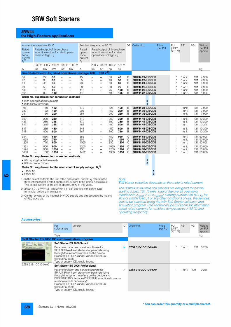
8122019 Arr Estado Solido
httpslidepdfcomreaderfullarr-estado-solido 1240
3RW Soft Starters
3RW44for High-Feature applications
1) In the selection table the unit rated operational current I e refers to thethree-phase motors rated operational current in the inside-delta circuitThe actual current of the unit is approx 58 of this value
2) 3RW44 2 3RW44 3 and 3RW44 4 soft starters with screw-typeterminals delivery time class A
3) Control by way of the internal 24 V DC supply and direct control by meansof PLC possible
Accessories
NoteSoft starter selection depends on the motors rated current
The 3RW44 solid-state soft starters are designed for normalstarting (class 10) (Inertia load of the overall operatingmechanism J Load lt 10 x J Motor starting current 350 x I e for20 s or similar load) For any other conditions of use the devicesshould be selected using the Win-Soft Starter selection andsimulation program See Technical Specifications for informationabout rated currents for ambient temperatures gt 40 degC andoperating frequency
Ambient temperature 40 degC Ambient temperature 50 degC DT Order No Priceper PU
PU(UNITSET M)
PS PG Weightper PUapprox
Ratedopera-
tionalcurrent I e
1)
Rated output of three-phaseinduction motors for rated opera-
tional voltage U e
Ratedopera-
tionalcurrent I e
Rated output of three-phaseinduction motors for rated
operational voltage U e
230 V 400 V 500 V 690 V 1000 V 200 V 230 V 460 V 575 V
A kW kW kW kW kW A hp hp hp hp kg
Inside-delta circuits rated operational voltage 400 600 V2)
50 -- 22 30 -- -- 45 -- -- 30 40 B 3RW44 22-BC5 1 1 unit 131 490062 -- 30 37 -- -- 55 -- -- 40 50 B 3RW44 23-BC5 1 1 unit 131 490081 -- 45 45 -- -- 73 -- -- 50 60 B 3RW44 24-BC5 1 1 unit 131 4900
99 -- 55 55 -- -- 88 -- -- 60 75 B 3RW44 25-BC5 1 1 unit 131 4900133 -- 75 90 -- -- 118 -- -- 75 100 B 3RW44 26-BC5 1 1 unit 131 4900161 -- 90 110 -- -- 142 -- -- 100 125 B 3RW44 27-BC5 1 1 unit 131 4900
Order No supplement for connection methods
bull With spring-loaded terminals 3bull With screw terminals 1
196 -- 110 132 -- -- 173 -- -- 125 150 B 3RW44 34-BC5 1 1 unit 131 7900232 -- 132 160 -- -- 203 -- -- 150 200 B 3RW44 35-BC5 1 1 unit 131 7900
281 -- 160 200 -- -- 251 -- -- 200 250 B 3RW44 36-BC5 1 1 unit 131 7900
352 -- 200 250 -- -- 312 -- -- 250 300 B 3RW44 43-BC5 1 1 unit 131 10300433 -- 250 315 -- -- 372 -- -- 300 350 B 3RW44 44-BC5 1 1 unit 131 10300542 -- 315 355 -- -- 485 -- -- 400 500 B 3RW44 45-BC5 1 1 unit 131 10300
617 -- 355 450 -- -- 546 -- -- 450 600 B 3RW44 46-BC5 1 1 unit 131 10300748 -- 400 500 -- -- 667 -- -- 600 750 B 3RW44 47-BC5 1 1 unit 131 10300
954 -- 560 630 -- -- 856 -- -- 750 950 C 3RW44 53-BC5 1 1 unit 131 500001065 -- 630 710 -- -- 954 -- -- 850 1050 C 3RW44 54-BC5 1 1 unit 131 500001200 -- 710 800 -- -- 1065 -- -- 950 1200 C 3RW44 55-BC5 1 1 unit 131 50000
1351 -- 800 900 -- -- 1200 -- -- 1050 1350 C 3RW44 56-BC5 1 1 unit 131 500001524 -- 900 1000 -- -- 1351 -- -- 1200 1500 C 3RW44 57-BC5 1 1 unit 131 500001680 -- 1000 1200 -- -- 1472 -- -- 1300 1650 C 3RW44 58-BC5 1 1 unit 131 50000
Order No supplement for connection methods
bull With spring-loaded terminals 2bull With screw terminals 6
Order No supplement for the rated control supply voltage U s3)
bull 115 V AC 3bull 230 V AC 4
Forsoft starters Version DT Order No Priceper PU PU(UNITSET M)
PS PG Weightper PUapprox
Type kg
Soft Starter ES 2006 PC communication program
Soft Starter ES 2006 Smart
Parameterization and service software forSIRIUS 3RW44 soft starters for parameterizingthrough the system interface on the deviceExecutes on PCPG under Windows 2000XPwithout PC cableType of supply CD single license
3ZS1 313-1CC10-0YA0 1 1 unit 131 0230
3ZS1 313-1CC10-0YA0 Soft Starter ES 2006 Professional
Parameterization and service software forSIRIUS 3RW44 soft starters for parameterizingthrough the system interface on the device andPROFIBUS DP interface (PROFIBUS as optional commu-nication module necessary)Executes on PCPG under Windows 2000XPwithout PC cableType of supply CD single license
A 3ZS1 313-2CC10-0YA0 1 1 unit 131 0230
8122019 Arr Estado Solido
httpslidepdfcomreaderfullarr-estado-solido 1340
3RW Soft Starters
3RW44for High-Feature applications
Spare parts
Forsoft starters
Version DT Order No Priceper PU
PU(UNITSET M)
PS PG Weightper PUapprox
Type kg
PC cables
For PCPG communication with SIRIUS 3RW44soft starters
through the system interface for connecting tothe serial interface of the PCPG
B 3UF7 940-0AA00-0 1 1 unit 131 0150
Box terminal blocks for soft starters
Box terminal blocks
3RW44 2 Included in del ivery
3RW44 3 bull Up to 70 mm2 3RT19 55-4G 1 1 unit 101 0237
bull Up to 120 mm2 3RT19 56-4G 1 1 unit 101 0270
3RW44 3 bull Up to 240 mm2 3RT19 66-4G 1 1 unit 101 0676
PROFIBUS Communication moduleModule to be plugged into the soft starter to connect thesoft starter to the PROFIBUS net
A 3RW4 900-0KC00 1 1 unit 131 0320
External display and operation module
to show and operate the fonctions supplied by the softstarter via externally mounted display and operationmodule(for example in the cubicle door)
A 3RW4 900-0AC00 1 1 unit 131 0320
Connection cable
from serial interface of 3RW44 soft starter to external dis-play and operation modulebull Length 05 m flat B 3UF7 932-0AA00-0 1 1 unit 131 0020bull Length 05 m round A 3UF7 932-0BA00-0 1 1 unit 131 0050bull Length10 m round A 3UF7 937-0BA00-0 1 1 unit 131 0100bull Length25 m round A 3UF7 933-0BA00-0 1 1 unit 131 0150
Covers for soft starters
Terminal covers for box terminals
Additional touch protection to be fitted at the boxterminals (2 units required per device)
3RW44 2 and3RW44 3
3RT19 56-4EA2 1 1 unit 101 0028
3RW44 4 3RT19 66-4EA2 1 1 unit 101 0038
Terminal covers for cable lugs and busbarconnections
3RW44 2 and3RW44 3
3RT19 56-4EA1 1 1 unit 101 0067
3RW44 4 3RT19 66-4EA1 1 1 unit 101 0124
Forsoft starters
Version DT Order No Priceper PU
PU(UNITSET M)
PS PG Weightper PUapprox
Type kg
Fans
Fans
3RW44 2 and3RW44 3
115 VAC 3RW49 36-8VX30 1 1 unit 131 0300230 VAC 3RW49 36-8VX40 1 1 unit 131 0300
3RW44 4 115 V AC 3RW49 47-8VX30 1 1 unit 131 0500230 VAC 3RW49 47-8VX40 1 1 unit 131 0500
3RW44 5 115 V AC 3RW49 57-8VX30 1 1 unit 131 0800230 VAC 3RW49 57-8VX40 1 1 unit 131 0800
You can order this quantity or a multiple thereof
8122019 Arr Estado Solido
httpslidepdfcomreaderfullarr-estado-solido 1440
3RW Soft Starters
3RW44for High-Feature applications
Function
Equipped with modern ergonomic user prompting theSIRIUS 3RW44 soft starters can be commissioned quickly and
easily using a keypad and a menu-prompted multi-line displaywith background lighting Motor starting and deceleration areoptimized quickly easily and safely with just a few settings in aselectable language Four-key operation and plain-text displaysfor each menu point guarantee full clarity at every moment of theparameterization and operation Measurement values and oper-ating values as well as warning messages and fault indicationsare output continuously on the front panel during operation andwhen control voltage is applied An external display and opera-tor module can be connected by means of a connecting cableto the soft starter thus enabling active indications and the like tobe read directly from the control cabinet door
The SIRIUS 3RW44 soft starters are equipped with optimumfunctionality An integral bypass contact system reduces thepower loss of the soft starter during operation This reliablyprevents heating of the switchgear environment TheSIRIUS 3RW44 soft starters have internal intrinsic deviceprotection This prevents thermal overloading of the powersections thyristors eg due to unacceptably high closingoperations
Wiring work for installing an additional motor overload relay is nolonger needed as the SIRIUS 3RW44 soft starters perform thisfunction too In addition they offer adjustable trip classes and athermistor motor protection function As an option the thyristorscan also be protected by SITOR semi-conductor fuses fromshort-circuiting And even inrush current peaks are reliablyavoided thanks to adjustable current limiting
As a further option the SIRIUS 3RW44 soft starters can beupgraded with a PROFIBUS DP module Thanks to their commu-nication capability and their programmable control inputs andrelay outputs the SIRIUS 3RW44 soft starters can be very easily
and quickly integrated in higher-level controllersIn addition a creep speed function is available for positioningand setting jobs With this function the motor can be controlledin both directions of rotation with reduced torque and an adjust-able low speed
On the other hand the SIRIUS 3RW44 soft starters offer a newcombined DC braking function for the fast stopping of drivingloads
Highlights bull Soft starting with breakaway pulse torque control or voltage
ramp and adjustable torque or current limiting as well as anycombination of these depending on load type
bull Integrated bypass contact system to minimize dissipatedpower
bull Various setting options for the starting parameters such asstarting torque starting voltage ramp-up and ramp-downtime and much more in three separate parameter sets
bull Start-up detectionbull Inside-delta circuit for savings in terms of size and equipment
costsbull Various ramp-down modes selectable free ramp-down
torque-controlled pump stopping combined DC brakingbull Solid-state motor overload and intrinsic device protectionbull Thermistor motor protectionbull Keypad with a menu-controlled multi-line graphic display with
background lighting
bull Interface for communication with the PC for more accuratesetting of the parameters as well as for control and monitoringbull Simple adaptation to the motor feederbull Simple mounting and commissioningbull Display of operating states and fault signalsbull Connection to PROFIBUS with optional PROFIBUS DP modulebull External display and operator modulebull System voltages from 200 to 690 V 50 to 60 Hzbull Applicable up to 60 degC (derating from 40 degC)
8122019 Arr Estado Solido
httpslidepdfcomreaderfullarr-estado-solido 1540
3RW Soft Starters
3RW44for High-Feature applications
Technical specifications
Type 3RW44 -BC3 3RW44 -BC4Terminal
Control electronics
Rated valuesRated control supply voltage A1A2PE V 115 AC 230 ACbull Tolerance -15+10 -15+10Rated control supply current STANDBY mA 30 20
Rated control supply current ONbull 3RW44 2 mA 300 170bull 3RW44 3 mA 500 250bull 3RW44 4 mA 750 400bull 3RW44 5 mA 450 200
Maximum current (pickup bypass)bull 3RW44 2 mA 1000 500bull 3RW44 3 mA 2500 1250bull 3RW44 4 mA 6000 3000bull 3RW44 5 mA 4500 2500
Rated frequency Hz 50 60 50 60bull Tolerance plusmn10 plusmn10
Type 3RW44 Terminal Factory presetting
Control electronics
Control inputsInput 1 IN1 Start motor right parameter set 1Input 2 IN2 No actionInput 3 IN3 No actionInput 4 IN4 Trip reset
Supply L+L-bull Rated operational current mA Approx 10 per input to DIN 19240bull Rated operational voltage L+ Internal voltage 24 V DC from inter-
nal supply through terminal L+ toIN1 IN4 Maximum load at L+approx 55 mA
L- External voltage DC external voltage(to DIN19240) through terminals
L- and IN1 IN4(min 12 V DC max 30 V DC)
Thermistor motor protection inputInput T1T2 PTC type A or Thermoclick Deactivated
Relay outputs (floating auxiliary contacts)Output 1 1314 ON periodOutput 2 2324 No actionOutput 3 3334 No actionOutput 4 959698 Group fault
Switching capacity of the relay outputs230 VAC-15 A 3 at 240 V24 VDC-13 A 1 at 24 VProtection against overvoltages Protection by means of Varistor through relay contactShort-circuit protection 4 A gLgG operational class
6 A quick (fuse is not included in scope of supply)
Protective functions
Motor protection functionsTrips in the event of Thermal overloading of the motor
Trip class to IEC 60947-4-1 Class 510152030 10Phase failure sensitivity gt 40
Overload warning yesReset and recovery ManualAutomatic ManualReset option after tripping ManualAutomatic ManualRecovery time min 1 30 1
Device protection functionsTrips in the event of Thermal overloading of the thyristorsReset option after tripping ManualAutomatic ManualRecovery time min 05
8122019 Arr Estado Solido
httpslidepdfcomreaderfullarr-estado-solido 1640
3RW Soft Starters
3RW44for High-Feature applications
Type 3RW44 Factory presetting
Control times and parameters
Control timesClosing delay (with connected control voltage) ms lt 50Closing delay (automatic mode) ms lt 4000Recovery time (closing command in active ramp-down) ms lt 100
Mains failure bridging timeControl supply voltage ms 100
Mains failure response timeLoad current circuit ms 100
Reclosing lockout after overload tripMotor protection trip min 1 30 1Device protection trip s 30
Setting options for startingVoltage ramp for starting voltage 20 100 30Torque control for starting torque 20 100 50Torque control for limit torque 20 200 150
Starting time s 0 360 20Maximum starting time s 1 1000 DeactivatedCurrent limit value 125 550 450
Breakaway voltage 40 100 80Breakaway time s 0 2 DeactivatedMotor heat output 0 100 0
Creep mode LeftRight runningSpeed factor as function of rated speed (n = n rated factor) 3 21 7Creep torque (reference variable depends on the motor used but isalways smaller than the rated torque of the motor)
20 100 50
Setting options for ramp-downTorque control for stopping torque 10 100 10Ramp-down time s 0 360 10Dynamic braking torque 20 100 50DC braking torque 20 100 50
Operating indicationsTest voltageTest mains phasesReady to start
Start active
Motor runningRamp-down active
Warningserror signalsMains voltage missingLeading-edge phase error
Phase failurebull L1bull L2bull L3
Missing load phasebull T1bull T2bull T3
Failurebull Contact element 1 (thyristor)bull Contact element 2 (thyristor)bull Contact element 3 (thyristor)
Flash memory faulty
Supply voltagebull Below 75 bull Below 85 bull Over 110
Current unbalance exceededThermal motor model overload
Prewarning limit exceededbull Motor heatingbull Time-related trip reserve
Bypass elements defectiveMains voltage too high
Device not namedWrong naming versionCurrent range exceeded
Motor blocking ndash shutdownCurrent limit exceeded
Power section
bull Overheatedbull OvertemperatureEmergency active
8122019 Arr Estado Solido
httpslidepdfcomreaderfullarr-estado-solido 1740
3RW Soft Starters
3RW44for High-Feature applications
1) Parameter motor left possible only in conjunction with creep mode
Type 3RW44 Factory presetting
Control times and parameters
Warningserror signals (contd)Temperature sensorbull Overloadbull Open-circuitbull Short-circuit
Ground faultbull Detectedbull Shutdown
Connection abort in manual modeMax number of starts exceeded I e limit value overshootundershoot
Cooling timebull Motor activebull Switch block active
Heat sink sensorbull Open-circuitbull Short-circuit
Quick-stop functionSwitch block faulty I e class setting not permissible
Control inputsInput 1 Motor right parameter set 1Input 2 No actionInput 3 No actionInput 4 Trip reset
Parameterizing options for control inputs 1 4 No actionLocal manual modeEmergency startCreep speedQuick-stopTrip reset
Motor right parameter set 1Motor left parameter set 11) Motor right parameter set 2Motor left parameter set 21) Motor right parameter set 3Motor left parameter set 31)
Relay outputsOutput 1 ON periodOutput 2 No actionOutput 3 No actionOutput 4 Group fault
Parameterizing options for relay outputs 1 3 No actionPAA output 1PAA output 2
Input 1Input 2Input 3Input 4
Ramp-upOperationBypassRamp-downON periodCommand motor on
FanDC braking contactor
Group warningGroup faultBus faultDevice error
Power onReady to start
Motor temperature sensors Deactivated DeactivatedThermoclickPTC type A
8122019 Arr Estado Solido
httpslidepdfcomreaderfullarr-estado-solido 1840
3RW Soft Starters
3RW44for High-Feature applications
1) Current limit on soft starter set to 350 I M
2) For intermittent duty S4 with ON period = 70 T u = 40 degC stand-aloneinstallation vertical The quoted operating frequencies do not apply forautomatic mode
3) Maximum adjustable rated motor current I M dependent on CLASS setting
Type 3RW44 -BC4 3RW44 -BC5 3RW44 -BC6
Power electronics
Rated operational voltage for inline circuit V 200 460 AC 400 600 AC 400 690 AC
Tolerance -15+10 -15+10 -15+10Rated operational voltage for inside-delta circuit V 200 460 AC 400 600 AC 400 600 ACTolerance -15+10 -15+10 -15+10
Rated frequency Hz 50 60Tolerance plusmn10
Continuous operation at 40 degC ( of I e) 115
Minimum load ( of set motor current I M) 8
Maximum conductor length between soft starter and motor m 200
Permissible installation height m 5000 (derating from 1000 see characteristics) higher on request
Permissible mounting position
Permissible ambient temperatureOperation degC 0 +60 (derating from +40)Storage degC -25 +80
Degree of protection IP00
Type 3RW44 22 3RW44 23 3RW44 24 3RW44 25 3RW44 26 3RW44 27
Power electronics
Rated operational current I e 29 36 47 57 77 93
Load rating with rated operational current I ebull Acc to IEC and ULCSA for individual mounting
at 405060 degC AC-53a A 292623 363229 474237 575145 776859 938272
Smallest adjustable rated motor current I Mfor the motor overload protection
A 5 7 9 11 15 18
Power lossbull In operation after completed ramp-up with uninterrupted rated
operational current (40 degC) approx W 8 10 32 36 45 55bull During starting with current limit set to 350 I M (40 degC) W 400 470 600 725 940 1160
Permissible rated motor current and starts per hour
bull Normal starting (Class 5)- Rated motor current I M
1) starting time 5 s A 29 36 47 57 77 93- Starts per hour2) 1h 41 34 41 41 41 41
- Rated motor current I M1)3) starting time 10 s A 29 36 47 57 77 93
- Starts per hour2) 1h 20 15 20 20 20 20
bull Normal starting (Class 10)- Rated motor current I M
1) starting time 10 s A 29 36 47 57 77 93- Starts per hour2) 1h 20 15 20 20 20 20
- Rated motor current I M1)3) starting time 20 s A 29 36 47 57 77 93
- Starts per hour2) 1h 10 6 10 10 8 8
bull Normal starting (Class 15)- Rated motor current I M
1) starting time 15 s A 29 36 47 57 77 93- Starts per hour2) 1h 13 9 13 13 13 13
- Rated motor current I M1)3) starting time 30 s A 29 36 47 57 77 93
- Starts per hour2) 1h 6 4 6 6 6 6
bull For heavy starting (Class 20)- Rated motor current I M
1) starting time 20 s A 29 36 47 57 73 88- Starts per hour2) 1h 10 6 10 10 10 10
- Rated motor current I M1)3) starting time 40 s A 29 36 47 57 73 88
- Starts per hour2) 1h 4 2 4 5 18 08
bull For very heavy starting (Class 30)- Rated motor current I M
1) starting time 30 s A 29 36 44 57 65 77- Starts per hour2) 1h 6 4 6 6 6 6
- Rated motor current I M1)3) starting time 60 s A 29 36 44 57 65 77
- Starts per hour2) 1h 18 08 33 15 2 1
8122019 Arr Estado Solido
httpslidepdfcomreaderfullarr-estado-solido 1940
3RW Soft Starters
3RW44for High-Feature applications
1) Current limit on soft starter set to 350 I M
2) For intermittent duty S4 with ON period = 70 T u = 40 degC stand-aloneinstallation vertical The quoted operating frequencies do not apply forautomatic mode
3) Maximum adjustable rated motor current I M dependent on CLASS setting
Type 3RW44 34 3RW44 35 3RW44 36
Power electronics
Rated operational current I e 113 134 162
Load rating with rated operational current I ebull Acc to IEC and ULCSA for individual mounting AC-53a
- at 40 degC A 113 134 162- at 50 degC A 100 117 145- at 60 degC A 88 100 125
Smallest adjustable rated motor current I Mfor the motor overload protection
A 22 26 32
Power lossbull In operation after completed ramp-up with uninterrupted rated
operational current (40 degC) approx W 64 76 95bull During starting with current limit set to 350 I M (40 degC) W 1350 1700 2460
Permissible rated motor current and starts per hour
bull Normal starting (Class 5)- Rated motor current I M
1) starting time 5 s A 113 134 162- Starts per hour2) 1h 41 39 41
- Rated motor current I M1)3) starting time 10 s A 113 134 162
- Starts per hour2) 1h 20 15 20
bull Normal starting (Class 10)- Rated motor current I M
1) starting time 10 s A 113 134 162- Starts per hour2) 1h 20 15 20
- Rated motor current I M1)3) starting time 20 s A 113 134 162
- Starts per hour2) 1h 9 6 7
bull Normal starting (Class 15)- Rated motor current I M
1) starting time 15 s A 113 134 162- Starts per hour2) 1h 13 9 12
- Rated motor current I M1)3) starting time 30 s A 113 134 162
- Starts per hour2) 1h 6 6 1
bull For heavy starting (Class 20)- Rated motor current I M
1) starting time 20 s A 106 125 147- Starts per hour2) 1h 9 9 10
- Rated motor current I M1)3) starting time 40 s A 106 125 147
- Starts per hour2) 1h 15 2 1
bull For very heavy starting (Class 30)- Rated motor current I M
1) starting time 30 s A 91 110 120
- Starts per hour2) 1h 6 6 6- Rated motor current I M
1)3) starting time 60 s A 91 110 120- Starts per hour2) 1h 2 2 2
8122019 Arr Estado Solido
httpslidepdfcomreaderfullarr-estado-solido 2040
3RW Soft Starters
3RW44for High-Feature applications
1) Current limit on soft starter set to 350 I M
2) For intermittent duty S4 with ON period = 70 T u = 40 degC stand-aloneinstallation vertical The quoted operating frequencies do not apply forautomatic mode
3) Maximum adjustable rated motor current I M dependent on CLASS setting
Type 3RW44 43 3RW44 44 3RW44 45 3RW44 46 3RW44 47
Power electronics
Rated operational current I e 203 250 313 356 432
Load rating with rated operational current I ebull Acc to IEC and ULCSA for individual mounting AC-53a
- at 40 degC A 203 250 313 356 432- at 50 degC A 180 215 280 315 385- at 60 degC A 156 185 250 280 335
Smallest adjustable rated motor current I Mfor the motor overload protection
A 40 50 62 71 86
Power lossbull In operation after completed ramp-up with uninterrupted rated
operational current (40 degC) approx W 89 110 145 174 232bull During starting with current limit set to 350 I M (40 degC) W 3350 4000 4470 5350 5860
Permissible rated motor current and starts per hour
bull Normal starting (Class 5)- Rated motor current I M
1) starting time 5 s A 203 250 313 356 432- Starts per hour2) 1h 41 41 41 41 39
- Rated motor current I M1)3) starting time 10 s A 203 250 313 356 432
- Starts per hour2) 1h 20 20 19 17 16
bull Normal starting (Class 10)- Rated motor current I M
1) starting time 10 s A 203 250 313 356 432- Starts per hour2) 1h 20 20 19 17 16
- Rated motor current I M1)3) starting time 20 s A 203 250 313 356 432
- Starts per hour2) 1h 9 10 6 4 5
bull Normal starting (Class 15)- Rated motor current I M
1) starting time 15 s A 203 240 313 325 402- Starts per hour2) 1h 13 13 10 13 11
- Rated motor current I M1)3) starting time 30 s A 203 240 313 325 402
- Starts per hour2) 1h 3 6 1 2 1
bull For heavy starting (Class 20)- Rated motor current I M
1) starting time 20 s A 195 215 275 285 356- Starts per hour2) 1h 10 10 10 10 10
- Rated motor current I M1)3) starting time 40 s A 195 215 275 285 356
- Starts per hour2) 1h 1 5 1 3 1
bull For very heavy starting (Class 30)- Rated motor current I M
1) starting time 30 s A 162 180 220 240 285
- Starts per hour2) 1h 6 6 6 6 6- Rated motor current I M
1)3) starting time 60 s A 162 180 220 240 285- Starts per hour2) 1h 3 3 3 2 1
8122019 Arr Estado Solido
httpslidepdfcomreaderfullarr-estado-solido 2140
3RW Soft Starters
3RW44for High-Feature applications
1) Current limit on soft starter set to 350 I M
2) For intermittent duty S4 with ON period = 70 T u = 40 degC stand-aloneinstallation vertical The quoted operating frequencies do not apply forautomatic mode
3) Maximum adjustable rated motor current I M dependent on CLASS setting
Type 3RW44 53 3RW44 54 3RW44 55 3RW44 56 3RW44 57 3RW44 58
Power electronics
Rated operational current I e 551 615 693 780 880 970
Load rating with rated operational current I ebull Acc to IEC and ULCSA for individual mounting AC-53a
- at 40 degC A 551 615 693 780 880 970- at 50 degC A 494 551 615 693 780 850- at 60 degC A 438 489 551 615 693 760
Smallest adjustable rated motor current I Mfor the motor overload protection
A 110 123 138 156 176 194
Power lossbull In operation after completed ramp-up with uninterrupted rated
operational current (40 degC) approx W 159 186 220 214 250 270bull During starting with current limit set to 350 I M (40 degC) W 7020 8100 9500 11100 13100 15000
Permissible rated motor current and starts per hour
bull Normal starting (Class 5)- Rated motor current I M
1) starting time 5 s A 551 615 693 780 880 970- Starts per hour2) 1h 41 41 37 33 22 17
- Rated motor current I M1)3) starting time 10 s A 551 615 693 780 880 970
- Starts per hour2) 1h 20 20 16 13 8 5
bull Normal starting (Class 10)- Rated motor current I M
1) starting time 10 s A 551 615 693 780 880 970- Starts per hour2) 1h 20 20 16 13 8 5
- Rated motor current I M1)3) starting time 20 s A 551 615 693 780 880 970
- Starts per hour2) 1h 10 9 6 4 03 03
bull Normal starting (Class 15)- Rated motor current I M
1) starting time 15 s A 551 615 666 723 780 821- Starts per hour2) 1h 13 13 11 9 8 8
- Rated motor current I M1)3) starting time 30 s A 551 615 666 723 780 821
- Starts per hour2) 1h 6 4 3 1 04 05
bull For heavy starting (Class 20)- Rated motor current I M
1) starting time 20 s A 551 591 633 670 710 740- Starts per hour2) 1h 10 10 7 8 8 9
- Rated motor current I M1)3) starting time 40 s A 551 591 633 670 710 740
- Starts per hour2) 1h 4 2 1 1 04 1
bull For very heavy starting (Class 30)- Rated motor current I M
1) starting time 30 s A 500 525 551 575 600 630
- Starts per hour2) 1h 6 6 6 6 6 6- Rated motor current I M
1)3) starting time 60 s A 500 525 551 575 600 630- Starts per hour2) 1h 2 1 1 1 15 1
8122019 Arr Estado Solido
httpslidepdfcomreaderfullarr-estado-solido 2240
3RW Soft Starters
3RW44for High-Feature applications
1) When connecting cable lugs to DIN 46235 use 3RT19 56-4EA1 terminalcover for conductor cross-sections from 95 mmsup2 to ensure phase spacing
2) When connecting cable lugs to DIN 46234 the 3RT19 66-4EA1 terminalcover must be used for conductor cross-sections of 240 mmsup2 and more aswell as DIN 46235 for conductor cross-sections of 185 mmsup2 and more tokeep the phase clearance
Type 3RW44 2 3RW44 3 3RW44 4 3RW44 5
Conductor cross-sections
Screw
terminals
Main conductors
with box terminal 3RT19 55-4G (55 kW) 3RT19 66-4G
Front clampingpoint connected
bull Finely stranded with end sleeve mm2 16 70 70 240bull Finely stranded without end sleeve mm2 16 70 70 240bull Stranded mm2 16 70 95 300
bull Ribbon cable conductors(number x width x thickness)
mm min 3 x 9 x 08max 6 x 155 x 08
min 6 x 9 x 08max 20 x 24 x 05
bull AWG conductors solid or stranded AWG 6 20 30 600 kcmil
Rear clamping pointconnected
bull Finely stranded with end sleeve mm2 16 70 120 185bull Finely stranded without end sleeve mm2 16 70 120 185bull Stranded mm2 16 70 120 240
bull Ribbon cable conductors(number x width x thickness)
mm min 3 x 9 x 08max 6 x 155 x 08
min 6 x 9 x 08max 20 x 24 x 05
bull AWG conductors solid or stranded AWG 6 20 250 500 kcmil
Both clamping
points connected
bull Finely stranded with end sleeve mm2 max 1 x 50 1 x 70 min 2 x 50 max 2 x 185
bull Finely stranded without end sleeve mm2 max 1 x 50 1 x 70 min 2 x 50 max 2 x 185bull Stranded mm2 max 2 x 70 max 2 x 70 max 2 x 240
bull Ribbon cable conductors(number x width x thickness)
mm max 2 x (6 x 155 x 08) max 2 x (20 x 24 x 05)
bull AWG conductors solid or stranded AWG max 2 x 10 min 2 x 20max 2 x 500 kcmil
bull Terminal screws M10 (hexagon socket AF4) M12 (hexagon socket AF5)- Pickup torque 10 12 20 22
90 110 180 195
Screwterminals
Main conductors
with box terminal 3RT19 56-4G
Front or rear clamp-ing point connected
bull Finely stranded with end sleeve mm2 16 120bull Finely stranded without end sleeve mm2 16 120bull Stranded mm2 16 120
bull Ribbon cable conductors(number x width x thickness)
mm min 3 x 9 x 08max 6 x 155 x 08
bull AWG conductors solid or stranded AWG 6 250 kcmil
Both clampingpoints connected
bull Finely stranded with end sleeve mm2 max 1 x 95 1 x 120bull Finely stranded without end sleeve mm2 max 1 x 95 1 x 120bull Stranded mm2 max 2 x 120
bull Ribbon cable conductors(number x width x thickness)
mm max 2 x (10 x 155 x 08)
bull AWG conductors solid or stranded AWG max 2 x 30
Screwterminals
Main conductors
Without box terminalrail connection
bull Finely stranded with cable lug mm2 16 951) 50 2402) 50 2402)
bull Stranded with cable lug mm2 25 1201) 70 2402) 70 2402)
bull AWG conductors solid or stranded AWG 4 250 kcmil 20 500 kcmil 10 500 kcmil
bull Connecting bar (max width) mm 17 25 60
bull Terminal screws M8 x 25 (AF13) M10 x 30 (AF17) M12 x 40- Pickup torque NM 10 14 14 24 20 35lbin 89 124 124 210 177 310
8122019 Arr Estado Solido
httpslidepdfcomreaderfullarr-estado-solido 2340
3RW Soft Starters
3RW44for High-Feature applications
Soft starters Type 3RW44
Conductor cross-sections
Auxiliary conductors (1 or 2 conductors can be connected)
Screw terminals
bull Solid mm2 2 x 05 25bull Finely stranded with end sleeve mm2 2 x 05 15
bull AWG cables- Solid or stranded AWG 2 x 20 14- Finely stranded with end sleeve AWG 2 x 20 16
bull Terminal screws- Pickup torque NM 07 09
lbin 7 8
Spring-loaded terminals
bull Solid mm2 2 x 025 25bull Finely stranded with end sleeve mm2 2 x 025 15bull AWG conductors solid or stranded AWG 2 x 24 14
Standard Parameters
Electromagnetic compatibility acc to EN 60947-4-2
EMC interference immunityElectrostatic discharge (ESD) EN 61000-4-2 plusmn4 kV contact discharge plusmn8 kV air discharge
Electromagnetic RF fields EN 61000-4-3 Frequency range 80 1000 MHz with 80 at 1 kHzDegree of severity 3 10 Vm
Conducted RF interference EN 61000-4-6 Frequency range 150 kHz 80 MHz with 80 at 1 kHzInterference 10 V
RF voltages and RF currents on conductorsBurst EN 61000-4-4 plusmn2 kV5 kHzSurge EN 61000-4-5 plusmn1 kV line to line
plusmn2 kV line to ground
EMC interference emission
EMC interference field strength EN55011 Limit value of Class A at 30 1000 MHz
Radio interference voltage EN55011 Limit value of Class A at 015 30 MHz
Is an RI suppression filter necessary
Degree of noise suppression A (industrial applications) no
8122019 Arr Estado Solido
httpslidepdfcomreaderfullarr-estado-solido 2440
3RW Soft Starters
3RW44for High-Feature applications
Fuse assignment
The coordination type to which the motor feeder with soft starteris mounted depends on the application-specific requirements
Normally fuseless mounting (combination of motor starter pro-tector and soft starter) is sufficient If type 2 coordination is to befulfilled semiconductor fuses must be fitted in the motor feeder
1) The rated motor current must be considered when selecting the devices
2) The types of coordination are explained in more detail in theTechnical information LV 1 T under ndash Fuseless Load Feeders
Inline circuit fuseless version
Soft starters Motor starter protectorscircuit-breakers1)
Rated current 440 V +10 Rated currentG1 Q1Type A Type A
Type of coordination 12) 3RW44 22 3RW44 27 I q = 32 kA 3RW44 34 and 3RW44 35 I q = 16 kA 3RW44 36 3RW44 57 I q = 65 kA
3RW44 22 29 3RV10 42-4HA10 503RW44 23 36 3RV10 42-4JA10 633RW44 24 47 3RV10 42-4KA10 75
3RW44 25 57 3RV10 42-4LA10 903RW44 26 77 3RV10 42-4MA10 1003RW44 27 93 3RV10 42-4MA10 100
3RW44 34 113 3VL17 16-2DD36 1603RW44 35 134 3VL17 16-2DD36 1603RW44 36 162 3VL37 25-2DC36 250
3RW44 43 203 3VL47 31-3DC36 3153RW44 44 250 3VL47 31-3DC36 3153RW44 45 313 3VL47 40-3DC36 400
3RW44 46 356 3VL47 40-3DC36 4003RW44 47 432 3VL57 50-3DC36 500
3RW44 53 551 3VL67 80-3DE36 8003RW44 54 615 3VL67 80-3DE36 8003RW44 55 693 3VL67 80-3DE36 800
3RW44 56 780 3VL77 10-3AB36 10003RW44 57 880 3VL77 10-3AB36 10003RW44 58 970 3VL77 12-3AB36 1200
8122019 Arr Estado Solido
httpslidepdfcomreaderfullarr-estado-solido 2540
3RW Soft Starters
3RW44for High-Feature applications
1) If the ramp-down function Combined braking is selected no brakingcontactor is requiredIf the ramp-down function DC braking is selected a braking contactormust also be used (see table for type)For applications with large centrifugal masses (J Load gt J Motor) werecommend the function DC braking
2) Additional auxiliary relay K4LZXRT4A4T30(3RW44 soft starter with rated control supply voltage 230 V AC)LZXRT4A4S15(3RW44 soft starter with rated control supply voltage 115 V AC)
3) The types of coordination are explained in more detail in theTechnical information LV 1 T under ndash Fuseless Load Feeders
Inline circuit fused version (line protection only)
Soft starters Line protections Line contactorsup to 400 V
Braking contactors1)2)
Rated current 690 V +5 Rated current Size (optional) (for typical circuit see page 633)G1 F1 K1 K2 K3Type A Type A Type Type Type
Type of coordination 13) I q = 65 kA
3RW44 22 29 3NA3 820-6 50 00 3RT10 34 3RT15 26 --3RW44 23 36 3NA3 822-6 63 00 3RT10 35 3RT15 26 --
3RW44 24 47 3NA3 824-6 80 00 3RT10 36 3RT15 35 --3RW44 25 57 3NA3 830-6 100 00 3RT10 44 3RT15 35 --3RW44 26 77 3NA3 132-6 125 1 3RT10 45 3RT10 24 3RT10 353RW44 27 93 3NA3 136-6 160 1 3RT10 46 3RT10 25 3RT10 36
3RW44 34 113 3NA3 244-6 250 2 3RT10 54 3RT10 34 3RT10 443RW44 35 134 3NA3 244-6 250 2 3RT10 55 3RT10 36 3RT10 453RW44 36 162 3NA3 365-6 500 3 3RT10 56 3RT10 44 3RT10 45
3RW44 43 203 2 x 3NA3 354-6 2 x 355 3 3RT10 64 3RT10 44 3RT10 543RW44 44 250 2 x 3NA3 354-6 2 x 355 3 3RT10 65 3RT10 44 3RT10 553RW44 45 313 2 x 3NA3 365-6 2 x 500 3 3RT10 75 3RT10 54 3RT10 56
3RW44 46 356 2 x 3NA3 365-6 2 x 500 3 3RT10 75 3RT10 54 3RT10 563RW44 47 432 2 x 3NA3 365-6 2 x 500 3 3RT10 76 3RT10 55 3RT10 64
3RW44 53 551 2 x 3NA3 365-6 2 x 500 3 3TF68 44-0CM7 3TF68 44-0CM7 3TF68 44-0CM73RW44 54 615 2 x 3NA3 365-6 2 x 500 3 3TF68 44-0CM7 3TF68 44-0CM7 3TF68 44-0CM73RW44 55 693 2 x 3NA3 365-6 2 x 500 3 3TF69 44-0CM7 3TF69 44-0CM7 3TF69 44-0CM7
3RW44 56 780 2 x 3NA3 365-6 2 x 500 3 3TF69 44-0CM7 3TF69 44-0CM7 3TF69 44-0CM73RW44 57 880 2 x 3NA3 365-6 2 x 500 3 2 x 3TF69 44-0CM7 2 x 3TF69 44-0CM7 2 x 3TF69 44-0CM7
3RW44 58 970 3 x 3NA3 365-6 3 x 500 3
8122019 Arr Estado Solido
httpslidepdfcomreaderfullarr-estado-solido 2640
3RW Soft Starters
3RW44for High-Feature applications
1) If the ramp-down function Combined braking is selected no brakingcontactor is requiredIf the ramp-down function DC braking is selected a braking contactormust also be used (see table for type)For applications with large centrifugal masses (J Load gt J Motor) werecommend the function DC braking
2) Additional auxiliary relay K4LZXRT4A4T30(3RW44 soft starter with rated control supply voltage 230 V AC)LZXRT4A4S15(3RW44 soft starter with rated control supply voltage 115 V AC)
3) The types of coordination are explained in more detail in theTechnical information LV 1 T under ndash Fuseless Load Feeders
Inline circuit fused version with 3NE1 SITOR all-range fuse (semiconductor and line protection)
Soft starters All-range fuses Line contactors upto 400 V
Braking contactors1)2)
Ratedcurrent
Rated current Voltage Size (optional) (for typical circuit see page 633)
G1 Frsquo1 K1 K2 K3Type A Type A V Type Type Type
Type of coordination 23) I q = 65 kA
3RW44 22 29 3NE1 020-2 80 690 +5 00 3RT10 34 3RT15 26 --
3RW44 23 36 3NE1 020-2 80 690 +5 00 3RT10 35 3RT15 26 --3RW44 24 47 3NE1 021-2 100 690 +5 00 3RT10 36 3RT15 35 --
3RW44 25 57 3NE1 022-2 125 690 +5 00 3RT10 44 3RT15 35 --3RW44 26 77 3NE1 022-2 125 690 +5 00 3RT10 45 3RT10 24 3RT10 353RW44 27 93 3NE1 024-2 160 690 +5 1 3RT10 46 3RT10 25 3RT10 36
3RW44 34 113 3NE1 225-2 200 690 +5 1 3RT10 54 3RT10 34 3RT10 443RW44 35 134 3NE1 227-2 250 690 +5 1 3RT10 55 3RT10 36 3RT10 453RW44 36 162 3NE1 227-2 250 690 +5 1 3RT10 56 3RT10 44 3RT10 45
3RW44 43 203 3NE1 230-2 315 600 +10 1 3RT10 64 3RT10 44 3RT10 543RW44 44 250 3NE1 331-2 350 460 +10 2 3RT10 65 3RT10 44 3RT10 553RW44 45 313 3NE1 333-2 450 690 +5 2 3RT10 75 3RT10 54 3RT10 56
3RW44 46 356 3NE1 334-2 500 690 +5 2 3RT10 75 3RT10 54 3RT10 563RW44 47 432 3NE1 435-2 560 690 +5 3 3RT10 76 3RT10 55 3RT10 64
3RW44 53 551 2 x 3NE1 334-2 500 690 +10 2 3TF68 44-0CM7 3TF68 44-0CM7 3TF68 44-0CM73RW44 54 615 2 x 3NE1 334-2 500 690 +10 2 3TF68 44-0CM7 3TF68 44-0CM7 3TF68 44-0CM73RW44 55 693 2 x 3NE1 334-2 500 690 +10 2 3TF69 44-0CM7 3TF69 44-0CM7 3TF69 44-0CM7
3RW44 56 780 2 x 3NE1 435-2 560 690 +10 3 3TF69 44-0CM7 3TF69 44-0CM7 3TF69 44-0CM7
3RW44 57 880 2 x 3NE1 435-2 560 690 +10 3 2 x 3TF69 44-0CM7 2 x 3TF69 44-0CM7 2 x 3TF69 44-0CM73RW44 58 970 2 x 3NE1 435-2 560 690 +10 3
8122019 Arr Estado Solido
httpslidepdfcomreaderfullarr-estado-solido 2740
3RW Soft Starters
3RW44for High-Feature applications
1) If the ramp-down function Combined braking is selected no brakingcontactor is requiredIf the ramp-down function DC braking is selected a braking contactor
must also be used (see table for type)For applications with large centrifugal masses (J Load gt J Motor) werecommend the function DC braking
2) Additional auxiliary relay K4LZXRT4A4T30(3RW44 soft starter with rated control supply voltage 230 V AC)
LZXRT4A4S15(3RW44 soft starter with rated control supply voltage 115 V AC)
3) The types of coordination are explained in more detail in theTechnical information LV 1 T under ndash Fuseless Load Feeders
Inline circuit fused version with 3NE or 3NC SITOR semiconductor fuse(semiconductor protection by fuse lead and overload protection by circuit-breaker)
Soft starters Semiconductor fuses minimum Semiconductor fuses maximum Semiconductor fuses (cylinder)
Ratedcurrent
Rated current Size Rated current Size Rated current Size
G1 F3 F3 F3Type A Type A Type A Type A
Type of coordination 23) I q = 65 kA
3RW44 22 29 3NE4 120 80 0 3NE4 121 100 0 3NC2 280 80 22 x 58
3RW44 23 36 3NE4 121 100 0 3NE4 122 125 0 3NC2 200 100 22 x 583RW44 24 47 3NE4 121 100 0 3NE4 122 125 0 3NC2 200 100 22 x 58
3RW44 25 57 3NE4 122 125 0 3NE4 124 160 03RW44 26 77 3NE4 124 160 0 3NE4 124 160 03RW44 27 93 3NE3 224 160 1 3NE3 333 450 2
3RW44 34 113 3NE3 225 200 1 3NE3 335 560 23RW44 35 134 3NE3 225 200 1 3NE3 335 560 23RW44 36 162 3NE3 227 250 1 3NE3 333 450 2
3RW44 43 203 3NE3 230-0B 315 1 3NE3 333 450 23RW44 44 250 3NE3 230-0B 315 1 3NE3 333 450 23RW44 45 313 3NE3 233 450 1 3NE3 336 630 2
3RW44 46 356 3NE3 333 450 2 3NE3 336 630 23RW44 47 432 3NE3 335 560 2 3NE3 338-8 800 2
3RW44 53 551 2 x 3NE3 335 560 2 3 x 3NE3 334-0B 500 23RW44 54 615 2 x 3NE3 335 560 2 3 x 3NE3 334-0B 500 23RW44 55 693 2 x 3NE3 335 560 2 3 x 3NE3 334-0B 500 2
3RW44 56 780 2 x 3NE3 336 630 2 2 x 3NE3 340-8 900 2
3RW44 57 880 2 x 3NE3 336 630 2 2 x 3NE3 340-8 900 23RW44 58 970 2 x 3NE3 336 630 2 2 x 3NE3 340-8 900 2
Soft starters Line contactorsup to 400 V
Braking contactors1)2) Motor starter protectors circuit-breakers
Max line protection
Ratedcurrent
(optional) (for typical circuit see page 633) 440 V +10 Rated current 690 V +5 Rated current Size
G1 K1 Q1 F1Type A Type Type Type Type A Type A
Type of coordination 23) 3RW44 22 3RW44 27 I q = 32 kA 3RW44 34 and 3RW44 35 I q = 16 kA 3RW44 36 3RW44 57 I q = 65 kA
3RW44 22 29 3RT10 34 3RT15 26 -- 3RV10 41-4HA10 50 3NA3 820-6 50 003RW44 23 36 3RT10 35 3RT15 26 -- 3RV10 41-4JA10 63 3NA3 822-6 63 003RW44 24 47 3RT10 36 3RT15 35 -- 3RV10 41-4KA10 75 3NA3 824-6 80 00
3RW44 25 57 3RT10 44 3RT15 35 -- 3RV10 41-4LA10 90 3NA3 830-6 100 003RW44 26 77 3RT10 45 3RT10 24 3RT10 35 3RV10 41-4MA10 100 3NA3 132-6 125 13RW44 27 93 3RT10 46 3RT10 25 3RT10 36 3RV10 41-4MA10 100 3NA3 136-6 160 1
3RW44 34 113 3RT10 54 3RT10 34 3RT10 44 3VL17 16-1DD36 160 3NA3 244-6 250 2
3RW44 35 134 3RT10 55 3RT10 36 3RT10 45 3VL17 16-1DD36 160 3NA3 244-6 250 23RW44 36 162 3RT10 56 3RT10 44 3RT10 45 3VL37 25-1DC36 250 3NA3 365-6 500 3
3RW44 43 203 3RT10 64 3RT10 44 3RT10 54 3VL47 31-1DC36 315 2 x 3NA3 354-6 2 x 355 33RW44 44 250 3RT10 65 3RT10 44 3RT10 55 3VL47 31-1DC36 315 2 x 3NA3 354-6 2 x 355 33RW44 45 313 3RT10 75 3RT10 54 3RT10 56 3VL47 40-1DC36 400 2 x 3NA3 365-6 2 x 500 3
3RW44 46 356 3RT10 75 3RT10 54 3RT10 56 3VL47 40-1DC36 400 2 x 3NA3 365-6 2 x 500 33RW44 47 432 3RT10 76 3RT10 55 3RT10 64 3VL57 50-1DC36 500 2 x 3NA3 365-6 2 x 500 3
3RW44 53 551 3TF68 44-0CM7 3TF68 44-0CM7 3TF68 44-0CM7 3VL67 80-1AB36 800 2 x 3NA3 365-6 2 x 500 33RW44 54 615 3TF68 44-0CM7 3TF68 44-0CM7 3TF68 44-0CM7 3VL67 80-1AB36 800 2 x 3NA3 365-6 2 x 500 33RW44 55 693 3TF69 44-0CM7 3TF69 44-0CM7 3TF69 44-0CM7 3VL67 80-1AB36 800 2 x 3NA3 365-6 2 x 500 3
3RW44 56 780 3TF69 44-0CM7 3TF69 44-0CM7 3TF69 44-0CM7 3VL77 10-1AB36 1000 2 x 3NA3 365-6 2 x 500 33RW44 57 880 2 x
3TF69 44-0CM72 x3TF69 44-0CM7
2 x3TF69 44-0CM7
3VL77 10-1AB36 1000 2 x 3NA3 365-6 2 x 500 3
3RW44 58 970 3VL77 12-1AB36 1200 3 x 3NA3 365-6 3 x 500 3
8122019 Arr Estado Solido
httpslidepdfcomreaderfullarr-estado-solido 2840
3RW Soft Starters
3RW44for High-Feature applications
1) The types of coordination are explained in more detail in theTechnical information LV 1 T under ndash Fuseless Load FeedersThe type of coordination 2 only refers to soft starters not to feeder compo-nents ( I q = 65 kA)
Inside-delta circuit fused version with 3NE or 3NC SITOR fuses(semiconductor protection by fuse lead and overload protection by circuit-breaker)
Soft starters Semiconductor fuses minimum Semiconductor fuses maximum Semiconductor fuses (cylinder)
Ratedcurrent
Rated current Size Rated current Size Rated current Size
G1 F3 F3 F3Type A Type A Type A Type A
Type of coordination 21)
3RW44 22 50 3NE4 120 80 0 3NE4 121 100 0 3NC2 280 80 22 x 58
3RW44 23 62 3NE4 121 100 0 3NE4 122 125 0 3NC2 200 100 22 x 583RW44 24 81 3NE4 121 100 0 3NE4 122 125 0 3NC2 200 100 22 x 58
3RW44 25 99 3NE4 122 125 0 3NE4 124 160 03RW44 26 133 3NE4 124 160 0 3NE4 124 160 03RW44 27 161 3NE3 224 160 1 3NE3 333 450 2
3RW44 34 196 3NE3 225 200 1 3NE3 335 560 23RW44 35 232 3NE3 225 200 1 3NE3 335 560 23RW44 36 281 3NE3 227 250 1 3NE3 333 450 2
3RW44 43 352 3NE3 230-0B 315 1 3NE3 333 450 23RW44 44 433 3NE3 230-0B 315 1 3NE3 333 450 23RW44 45 542 3NE3 233 450 1 3NE3 336 630 2
3RW44 46 617 3NE3 333 450 2 3NE3 336 630 23RW44 47 748 3NE3 335 560 2 3NE3 338-8 800 2
3RW44 53 954 2 x 3NE3 335 560 2 3 x 3NE3 334-0B 500 23RW44 54 1065 2 x 3NE3 335 560 2 3 x 3NE3 334-0B 500 23RW44 55 1200 2 x 3NE3 335 560 2 3 x 3NE3 334-0B 500 2
3RW44 56 1351 2 x 3NE3 336 630 2 2 x 3NE3 340-8 900 2
3RW44 57 1524 2 x 3NE3 336 630 2 3 x 3NE3 340-8 900 23RW44 58 1680 2 x 3NE3 336 630 2 3 x 3NE3 340-8 900 2
Soft starters Line contactorsup to 400 V
Motor starter protectors cirduit-breakers
Line protections
Ratedcurrent
(optional) 440 V +10 Rated current 690 V +5 Rated current Size
G1 K1 Q1 F1Type A Type Type A Type A
Type of coordination 21)
3RW44 22 50 3RT10 36-1AP04 3RV10 4-4KA10 75 3NA3 824-6 80 003RW44 23 62 3RT10 44-1AP04 3RV10 4-4LA10 90 3NA3 830-6 100 003RW44 24 81 3RT10 46-1AP04 3RV10 4-4MA10 100 3NA3 132-6 125 1
3RW44 25 99 3RT10 54-1AP36 3VL27 16-DC36 160 3NA3 136-6 160 13RW44 26 133 3RT10 55-6AP36 3VL27 16-DC36 160 3NA3 240-6 200 23RW44 27 161 3RT10 56-6AP36 3VL37 20-DC36 200 3NA3 244-6 250 2
3RW44 34 196 3RT10 64-6AP36 3VL37 25-DC36 250 3NA3 360-6 400 3
3RW44 35 232 3RT10 65-6AP36 3VL47 31-DC36 315 3NA3 360-6 400 33RW44 36 281 3RT10 66-6AP36 3VL47 40-DC36 400 2 x 3NA3 360-6 2 x 400 3
3RW44 43 352 3RT10 75-6AP36 3VL47 40-DC36 400 2 x 3NA3 365-6 2 x 500 33RW44 44 433 3RT10 76-6AP36 3VL57 50-DC36 500 2 x 3NA3 365-6 2 x 500 33RW44 45 542 3TF68 44-0CM7 3VL57 63-DC36 800 3 x 3NA3 365-6 3 x 500 3
3RW44 46 617 3TF68 44-0CM7 3VL67 80-AB36 800 3 x 3NA3 365-6 3 x 500 33RW44 47 748 3TF69 3VL67 80-AB36 1000 3 x 3NA3 365-6 3 x 500 3
3RW44 53 954 2 x 3TF68 44-0CM7 3VL77 10-AB36 1000 3 x 3NA3 365-6 3 x 500 33RW44 54 1065 2 x 3TF68 44-0CM7 3VL77 12-AB36 1250 3 x 3NA3 365-6 3 x 500 33RW44 55 1200 2 x 3TF69 44-0CM7 3VL87 16-AB36 1600 3 x 3NA3 365-6 3 x 500 3
3RW44 56 1351 2 x 3TF69 44-0CM7 3VL87 16-AB36 1600 3 x 3NA3 372 3 x 630 33RW44 57 1524 2 x 3TF69 44-0CM7 3VL87 16-AB36 1600 3 x 3NA3 372 3 x 630 33RW44 58 1680 3WL12 20 2000 2 x 3NA3 480 2 x 1000 4
8122019 Arr Estado Solido
httpslidepdfcomreaderfullarr-estado-solido 2940
3RW Soft Starters
3RW44for High-Feature applications
Characteristic curves
Motor protection tripping characteristics for 3RW44(with symmetry)
Admissible mounting height
The admissible operational voltage is reduced to 460 V with a mountingheight of more than 2000 m
Motor protection characteristics for 3RW44(with phase unbalance)
e
2 4 6 101
Class 10 Class 15 Class 20
100
101
102
103
2
4
6
2
4
6
2
4
6
Class 5 Class 30
N S B 0
_ 0 1 5 0 0 a
[ s ]
x
T r i p p i n g t i m e
85
105
70
75
80
90
95
100
N S B 0
_ 0 1 7 0 4
0 1000 2000 3000 4000 5000 O p e r
a t i o n a
l r a
t e d c u r r e n
t I
i n
Mounting height in m
e
e
1001
Class 10 Class 15 Class 20
100
101
102
103
2
4
6
2
4
6
2
4
6
Class 5 Class 30
N S B 0
_ 0 1 7 0 6
[ s ]
x10
T r i p p
i n g
t i m e
8122019 Arr Estado Solido
httpslidepdfcomreaderfullarr-estado-solido 3040
3RW Soft Starters
3RW44for High-Feature applications
More information
Application examples for normal starting (Class 10)
Application examples for heavy starting (Class 20)
Application examples for very heavy starting (Class 30)
NoteThese tables present sample setting values and device sizesThey are intended only for the purposes of information and arenot binding The setting values depend on the application inquestion and must be optimized during commissioningThe soft starter dimensions should be checked where necessarywith the Win-Soft Starter software or with the help ofTechnical Assistance
Normal starting Class 10 (up to 20 s with 350 I n motor)The soft starter rating can be selected to be as high as the rating of the motor used
Application Conveyor belts Roller conveyors Compressors Small ventilators Pumps Hydraulic pumps
Starting parameters
bull Voltage ramp and currentlimiting- Starting voltage 70 60 50 30 30 30- Starting time s 10 10 10 10 10 10- Current limit value Deactivated Deactivated 4 x I M 4 x I M Deactivated Deactivated
bull Torque ramp- Starting torque 60 50 40 20 10 10- End torque 150 150 150 150 150 150- Starting time 10 10 10 10 10 10
bull Breakaway pulse Deactivated (0 ms) Deactivated (0 ms) Deactivated (0 ms) Deactivated (0 ms) Deactivated (0 ms) Deactivated (0 ms)
Ramp-down mode Smoothramp-down
Smoothramp-down
Free ramp-down Free ramp-down Pump ramp-down Free ramp-down
Heavy starting Class 20 (up to 40 s with 350 I n motor)The soft starter has to be selected one rating class higher than the motor used
Application Stirrers Centrifuges Milling machines
Starting parameters
bull Voltage ramp and currentlimiting- Starting voltage 30 30 30- Starting time s 30 30 30- Current limit value 4 x I M 4 x I M 4 x I M
bull Torque ramp- Starting torque 30 30 30- End torque 150 150 150- Starting time 30 30 30
bull Breakaway pulse Deactivated (0 ms) Deactivated (0 ms) Deactivated (0 ms)
Ramp-down mode Free ramp-down Free ramp-down Free ramp-down or DC braking
Very heavy starting Class 30 (up to 60 s with 350 I n motor)The soft starter has to be selected two rating classes higher than the motor used
Application Large ventilators Mills Breakers Circular sawbandsaws
Starting parameters
bull Voltage ramp and currentlimiting- Starting voltage 30 50 50 30- Starting time s 60 60 60 60- Current limit value 4 x I M 4 x I M 4 x I M 4 x I M
bull Torque ramp- Starting torque 20 50 50 20- End torque 150 150 150 150- Starting time 60 60 60 60
bull Breakaway pulse Deactivated (0 ms) 80 300 ms 80 300 ms Deactivated (0 ms)
Ramp-down mode Free ramp-down Free ramp-down Free ramp-down Free ramp-down
8122019 Arr Estado Solido
httpslidepdfcomreaderfullarr-estado-solido 3140
3RW Soft Starters
3RW44for High-Feature applications
Circuit concept
The SIRIUS 3RW44 soft starters can be operated in two differenttypes of circuit
bull Inline circuitThe controls for isolating and protecting the motor are simplyconnected in series with the soft starter The motor isconnected to the soft starter with three leads
bull Inside-delta circuitThe wiring is similar to that of wye-delta starters The phases ofthe soft starter are connected in series with the individual motorwindings The soft starter then only has to carry the phasecurrent amounting to about 58 of the rated motor current(conductor current)
Comparison of the types of circuit
Inline circuitRated current I e corresponds to the rated motor current I n3 leads to the motor
Inside-delta circuit
Rated current I e corresponds to approx 58 of the rated motorcurrent I n6 leads to the motor (as with wye-delta starters)
Which circuit
Using the inline circuit involves the lowest wiring complexityIf the soft starter to motor connections are long this contactsequence is preferableWith the inside-delta circuit there is double the wiring complexitybut a smaller size of device can be used at the same rating
Thanks to choosing the operational mode between the inline cir-cuit and inside-delta circuit the most favorable solution can al-ways be chosen
The braking function is possible only in the inline circuit
Configuration
The 3RW44 solid-state soft starters are designed for normalstarting In case of heavy starting or increased starting
frequency a larger device must be selectedFor long starting times it is recommended to have a PTC ther-mistor detector in the motor This also applies for the ramp-downmodes smooth ramp-down pump ramp-down and DC brakingbecause during the ramp-down time in these modes an addi-tional current loading applies in contrast to free ramp-down
In the motor feeder between the SIRIUS 3RW soft starter and themotor no capacitive elements are permitted (eg no reactive-power compensation equipment) In addition neither staticsystems for reactive-power compensation nor dynamic PFC(Power Factor Correction) must be operated in parallel duringstarting and ramp-down of the soft starter This is important toprevent faults arising on the compensation equipment andor thesoft starter
All elements of the main circuit (such as fuses and controls)
should be dimensioned for direct starting following the localshort-circuit conditions Fuses switching devices and overloadrelays must be ordered separately
The harmonic component load for starting currents must betaken into consideration for the selection of motor starterprotectors (selection of release)
NoteWhen switching on three-phase current motors voltage dropsnormally will occur with all types of starters (direct starters star- delta starters soft starters) On principle the feeding transformermust be configured such that when starting the motor thevoltage drop must occur within the admissible tolerance Whenthe feeding transformer is designed quite scarce the control vol- tage (being independent of the main voltage) should be sup- plied with a separate circuit in order to prevent the soft starterfrom switching off
Serial PC interface PROFIBUS DP communication moduleand parameterizing and operating software Soft Starter ES
The solid-state 3RW44 soft starters have a PC interface forcommunicating with the Soft Starter ES 2006 Smart software orto be connected to an external operating and monitoring mod-ule When using the optional communication module PROFIBUSthe 3RW44 soft starter can be connected to the PROFIBUS netand can communicate via GSD file or software Soft Starter ES2006 Professional
Manual for SIRIUS 3RW44
Besides containing all important information on planning com-missioning and servicing the manual also contains suggestedcircuits and the technical specifications for all devices
Win-Soft Starter selection and simulation program
With this software you can simulate and select all Siemens softstarters taking into account various parameters such as mainsproperties motor and load data and special applicationrequirements
The software is a valuable tool which makes complicatedlengthy manual calculations for determining the required softstarters superfluous
You can order the CD-ROM under the following order numberOrder No E20001-D1020-P302-V2-7400
More information can be found on the Internet athttpwwwsiemenscomsoftstarter
8122019 Arr Estado Solido
httpslidepdfcomreaderfullarr-estado-solido 3240
3RW Soft Starters
3RW44for High-Feature applications
SIRIUS soft starter training course (SD-SIRIUSO)
Siemens offers a 2-day training course on the SIRIUS solid-statesoft starters to keep customers and own personnel up-to-date on
configuring commissioning and servicing issuesPlease direct enquiries and applications to
AampD PT 4 (Trainings-Center Erlangen)Werner-von-Siemens-Str 65D-91052 ErlangenTelefon ++49 9131 729262Telefax ++49 9131 728172sibrainindustrysiemenscomhttp wwwsiemenscomsitrain
8122019 Arr Estado Solido
httpslidepdfcomreaderfullarr-estado-solido 3340
3RW Soft Starters
Project planning aids
Dimensional drawings
3RW44 2 3RW44 3 and 3RW44 4 for High-Feature applications
TypeDimension(mm)
a b c d e f g h I k l m n o p q
3RW44 2 180 170 37 11 167 100 240 270 180 148 75 153 7 184 66 M6 10 Nm
3RW44 3 180 170 37 17 167 100 240 270 180 148 75 153 7 198 9 M6 10 Nm
3RW44 4 210 210 48 25 190 140 269 298 205 166 16 166 9 230 11 M8 15 Nm
8122019 Arr Estado Solido
httpslidepdfcomreaderfullarr-estado-solido 3440
3RW Soft Starters
Project planning aids
3RW44 5 for High-Feature applications
147
173
195
118
N S B 0_
0 1 6 5 3
261
290
249
162
152
6 2 3
1 0 5
2 5 3
1 6 5
76
44
470
510
1
5 5
2
0Oslash14 40
6 3 8 5
5 9 0
8122019 Arr Estado Solido
httpslidepdfcomreaderfullarr-estado-solido 3540
3RW Soft Starters
Project planning aids
Schematics
1) Permissible values for main and control voltagesee Technical Specifications
3RW44 connection examples for main and control circuits
Main circuit Control circuitPossibility 1a Possibility 1Inline circuit with circuit-breaker and SITOR fuse(semiconductor protection only)
Control by pushbutton
Main circuit
Possibility 1b Possibility 1cInline circuit with full-rangeprotection (line andsemiconductor protection)
Inline circuit with line andSITOR fuse(semiconductor protection only)
Q1
L3L2L1
G1
F3
T1 T2 T3
M1
N S B 0_
0 1 4 9 0 a
L1 L2 L3
V1U1 W1
MPE 3~
3NPE 400 V AC 50 Hz
(optionalsemiconductorprotection fuse)
13 14 23 24 33 34 95 9896 +
T1 T2IN4IN3IN2IN1L-L+A1
A2
NPE
PE
G1
F2
NSB0_01494a
S t a r t
S 2
R e s e t S
3
StopS1
L1
On periodGrouperror
N o a c t i o n
N o a c t i o n
Noaction
PTC type Aor
Thermoclick
Noaction
1NPE 230 V AC 50 Hz
M o t o r o
n r i g h t
P S
1
1)
8122019 Arr Estado Solido
httpslidepdfcomreaderfullarr-estado-solido 3640
3RW Soft Starters
Project planning aids
1) Permissible values for main and control voltagesee Technical Specifications
2) Caution Risk of restartingThe start command (eg from the PLC) must be reset prior to a resetcommand because a new automatic restart will take place automaticallyif a start command is active after the reset command This appliesespecially in case of motor protection trippingFor safety reasons we recommend incorporating the group error output(terminals 95 and 96) in the controller
Main circuit Control circuit
Possibility 2 Possibility 2Inline circuit with main contactor Control of a main contactor and control by means of PLC
Q1
L3L2L1
G1
K1
F3
L1 L2 L3
T1 T2 T3
M1
N S B 0_
0 1 4 9 5 a
V1U1 W1
MPE 3~
1)
(optionalsemiconductorprotection)
(optional linecontactor if floatingswitching of themotor is planned)
3NPE 400 V AC 50 Hz
13 14 23 24 33 34 95 9896+
T1 T2IN4IN3IN2IN1L-L+A1
A2
NPE
PE
G1
K1NSB0_01496a
F2+24 V DC
M
L1 1NPE AC 230 V 50 Hz1)
Switch-on duration
M o t o r r i g h t
T r i p R e s e t
PLC outputs PLC inputs
N o a c t i o n
N o a c t i o n
No action No action
Group error
PTC type A Thermoclick
(optional line contactorif floating switchingof the motor is planned)
P S 1
ResetStart 2)
8122019 Arr Estado Solido
httpslidepdfcomreaderfullarr-estado-solido 3740
3RW Soft Starters
Project planning aids
1) Permissible values for main and control voltagesee Technical Specifications
2) Caution Risk of restartingThe start command (eg from the PLC) must be reset prior to a resetcommand because a new automatic restart will take place automaticallyif a start command is active after the reset command This applies espe-cially in case of motor protection trippingFor safety reasons we recommend incorporating the group error output(terminals 95 and 96) in the controller
3) If the ramp-down function Combined braking is selected no brakingcontactor is requiredIf the ramp-down function DC braking is selected a braking contactormust be used in addition Type see Fuse Coordination (inline circuit) onpages 621 to 623For applications with large centrifugal masses (J Load gt J Motor) werecommend the function DC brakingThe output 2 must be switched over to DC braking contactor
4) Auxiliary relay K4 egLZXRT4A4T30 (230 V AC rated control supply voltage)LZXRT4A4S15 (115 V AC rated control supply voltage)
Main circuit Control circuit
Possibility 3a Possibility 3aInline circuit with ramp-down function DC braking3)
(for device types 3RW44 22 to 3RW44 25)Control of the braking contactor3)
Main circuit Control circuit
Possibility 3b Possibility 3bInline circuit with ramp-down function DC braking3)
(for device types 3RW44 26 to 3RW44 47)Control of the braking contactor3)
Q1
L3L2
G1
F3
T1 T2 T3
M1
N S B 0_
0 1 5 0 1 a
L1 L2 L3
V1U1 W1
M
K2 K2 K2
PE 3~
1)
2
(optionalsemi-conductorprotection)
L1 3NPE 400 V AC 50 Hz
13 14 23 24 33 34 95 9896 +
T1 T2IN4IN3IN2IN1L-L+A1
A2
NPE
PEG1
K2NSB0_01502
R e s e t
M Start Reset
+24 V DC
K2
F2
1)
2)
No action Group error
N o a c t i o n
N o a c t i o n
On period
PLC output
PTC type Aor
Thermoclick
L1 1NPE 230 V AC 50 Hz
DC braking contactor 3)
K2 K33 3
G1
F3
T1 T2 T3
M1
N S B 0_
0 1
5 0 3 a
L1 L2 L3
V1U1 W1
MPE 3~
Q1
L3L2
1)
(optionalsemi-conductorprotection)
L1 3NPE 400 V AC 50 Hz
13 14 23 24 33 34 95 9896 +
T1 T2IN4IN3IN2IN1L-L+A1
A2
NPE
PE
G1
K4
NSB0_01504
R e s e t
K4 K4
K3 K2
K2 K3
+24 V DC
M Start Reset
F2
1)
2)
4)
PLC output
No action Group error
N o a c t i o n
N o a c t i o n
ON period
PTC type Aor
Thermoclick
M o t o r o n r i g h t
L1 1NPE 230 V AC 50 Hz
DC braking contactor 3)
8122019 Arr Estado Solido
httpslidepdfcomreaderfullarr-estado-solido 3840
3RW Soft Starters
Notes
1) Permissible values for main and control voltagesee Technical Specifications
2) Caution Risk of restartingThe start command (eg from the PLC) must be reset prior to a resetcommand because a new automatic restart will take place automaticallyif a start command is active after the reset command This appliesespecially in case of motor protection trippingFor safety reasons we recommend incorporating the group error output(terminals 95 and 96) in the controller
Main circuit Control circuit
Possibility 4a Possibility 4b Possibility 4Inside-delta circuit Change of direction of rotation for
inside-delta circuitControl by means of PLC
13 14 23 24 33 34 95 9896+
T1 T2IN4IN3IN2IN1L-L+A1
A2
NPE
PEG1
NSB0_01498a
+24 V DC
M
F2
L1 1NPE AC 230 V 50 Hz1)
2)
R e s e t
Switch-onduration
No action
Group error
N o a c t i o n
N o a c t i o n
No action
PTC type A orThermoclick
M o t o r r i g h t
PLC outputs PLC inputs
Start Reset
7
8122019 Arr Estado Solido
httpslidepdfcomreaderfullarr-estado-solido 3940
Appendix
Conditions of sale and delivery
Terms and Conditions of Sale and Delivery
By using this catalog you can acquire hardware and softwareproducts described therein from the Siemens AG subject to the
following terms Please note The scope the quality and the con-ditions for supplies and services including software productsby any Siemens entity having a registered office outside of Ger-many shall be subject exclusively to the General Terms andConditions of the respective Siemens entity
For customers with a seat or registered office in theFederal Republic of Germany
The bdquoGeneral Terms of Paymentldquo as well as the bdquoGeneral Condi-tions for the Supply of Products and Services of the Electricaland Electronics Industryldquo shall apply
For software products the bdquoGeneral License Conditions for Soft-ware Products for Automation and Drives for Customers with aSeat or registered Office in Germanyldquo shall apply
For customers with a seat or registered office outside of
Germany The bdquoGeneral Terms of Paymentldquo as well as the bdquoGeneral Condi-tions for Supplies of Siemens Automation and Drives for Cus-tomers with a Seat or registered Office outside of Germanyldquo shallapply
For software products the bdquoGeneral License Conditions for Soft-ware Products for Automation and Drives for Customers with aSeat or registered Office outside of Germanyldquo shall apply
General
The prices are in 991404 (Euro) ex works exclusive packaging
The sales tax (value added tax) is not included in the pricesIt shall be debited separately at the respective rate according tothe applicable legal regulations
In addition to the prices of products which include silver plump
aluminum andor copper surcharges may be calculated if therespective limits of the notes are exceeded The respective note(eg source German newspaper bdquoHandesblattldquo in categorybdquodeutsche Edelmetalleldquo and bdquoMetallverarbeiterldquo) for silver (bdquover-arbeitetes Silberldquo) plump (bdquoBlei in Kabelnldquo) aluminum (bdquoAlumin-ium in Kabelnldquo) and copper (bdquoElektrolytkupferldquo bdquoDEL-Notizldquo) re-spectively of the day the order or rather the on call order isreceived is decisive for the calculation of the surcharges
Surcharges of copper shall be calculated for Drives at a note(bdquoDEL-Notizldquo) above EUR 22500 100 Kg and for chokes trans-formers above EUR 15000 100 kg
Surcharges shall be charged based on the quantities of the ma-terials which are contained in the relevant products
Prices are subject to change without prior notice We will debitthe prices valid at the time of delivery
The dimensions are in mm In Germany according to the Ger-man law on units in measuring technology data in inches onlyapply to devices for export
Illustrations are not binding
Insofar as there are no remarks on the corresponding pages- especially with regard to data dimensions and weights given -these are subject to change without prior notice
Comprehensive Terms and Conditions of Sale and Delivery areavailable free of charge from your local Siemens business officeunder the following Order Nos
bull 6ZB5310-0KR30-0BA0(for customers based in the Federal Republic of Germany)
bull 6ZB5310-0KS53-0BA0(for customers based outside of theFederal Republic ofGermany)
or download them from the Internethttpwwwsiemenscomautomationmall (Germany AampD Mall Online-Help System)
Export regulations
The products listed in this catalog price list may be subject toEuropean German andor US export regulations
Therefore any export requiring a license is subject to approvalby the competent authorities
According to current provisions the following export regulations
must be observed with respect to the products featured in thiscatalog price list
Even without a label or with an ldquoAL Nldquo or ldquoECCN Nldquo authoriza-tion may be required due to the final destination and purpose forwhich the goods are to be used
The deciding factors are the AL or ECCN export authorizationindicated on order confirmations delivery notes and invoices
Errors excepted and subject to change without prior notice
AampDVuLEn 060306
AL Number of the German Export List
Products marked other than ldquoNldquo require an exportlicenseIn the case of software products the export des-ignations of the relevant data medium must alsobe generally adhered to
Goods labeled with an ldquoAL not equal to Nldquo aresubject to a European or German export authori-zation when being exported out of the EU
ECCN Export Control Classification Number
Products marked other than ldquoNldquo are subject to a
reexport license to specific countriesIn the case of software products the exportdesignations of the relevant data medium mustalso be generally adhered to
Goods labeled with an ldquoECCN not equal to Nldquo aresubject to a US re-export authorization
_ _ _ _
8122019 Arr Estado Solido
httpslidepdfcomreaderfullarr-estado-solido 4040
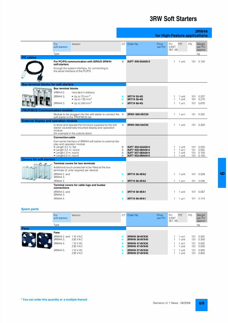
8122019 Arr Estado Solido
httpslidepdfcomreaderfullarr-estado-solido 1340
3RW Soft Starters
3RW44for High-Feature applications
Spare parts
Forsoft starters
Version DT Order No Priceper PU
PU(UNITSET M)
PS PG Weightper PUapprox
Type kg
PC cables
For PCPG communication with SIRIUS 3RW44soft starters
through the system interface for connecting tothe serial interface of the PCPG
B 3UF7 940-0AA00-0 1 1 unit 131 0150
Box terminal blocks for soft starters
Box terminal blocks
3RW44 2 Included in del ivery
3RW44 3 bull Up to 70 mm2 3RT19 55-4G 1 1 unit 101 0237
bull Up to 120 mm2 3RT19 56-4G 1 1 unit 101 0270
3RW44 3 bull Up to 240 mm2 3RT19 66-4G 1 1 unit 101 0676
PROFIBUS Communication moduleModule to be plugged into the soft starter to connect thesoft starter to the PROFIBUS net
A 3RW4 900-0KC00 1 1 unit 131 0320
External display and operation module
to show and operate the fonctions supplied by the softstarter via externally mounted display and operationmodule(for example in the cubicle door)
A 3RW4 900-0AC00 1 1 unit 131 0320
Connection cable
from serial interface of 3RW44 soft starter to external dis-play and operation modulebull Length 05 m flat B 3UF7 932-0AA00-0 1 1 unit 131 0020bull Length 05 m round A 3UF7 932-0BA00-0 1 1 unit 131 0050bull Length10 m round A 3UF7 937-0BA00-0 1 1 unit 131 0100bull Length25 m round A 3UF7 933-0BA00-0 1 1 unit 131 0150
Covers for soft starters
Terminal covers for box terminals
Additional touch protection to be fitted at the boxterminals (2 units required per device)
3RW44 2 and3RW44 3
3RT19 56-4EA2 1 1 unit 101 0028
3RW44 4 3RT19 66-4EA2 1 1 unit 101 0038
Terminal covers for cable lugs and busbarconnections
3RW44 2 and3RW44 3
3RT19 56-4EA1 1 1 unit 101 0067
3RW44 4 3RT19 66-4EA1 1 1 unit 101 0124
Forsoft starters
Version DT Order No Priceper PU
PU(UNITSET M)
PS PG Weightper PUapprox
Type kg
Fans
Fans
3RW44 2 and3RW44 3
115 VAC 3RW49 36-8VX30 1 1 unit 131 0300230 VAC 3RW49 36-8VX40 1 1 unit 131 0300
3RW44 4 115 V AC 3RW49 47-8VX30 1 1 unit 131 0500230 VAC 3RW49 47-8VX40 1 1 unit 131 0500
3RW44 5 115 V AC 3RW49 57-8VX30 1 1 unit 131 0800230 VAC 3RW49 57-8VX40 1 1 unit 131 0800
You can order this quantity or a multiple thereof
8122019 Arr Estado Solido
httpslidepdfcomreaderfullarr-estado-solido 1440
3RW Soft Starters
3RW44for High-Feature applications
Function
Equipped with modern ergonomic user prompting theSIRIUS 3RW44 soft starters can be commissioned quickly and
easily using a keypad and a menu-prompted multi-line displaywith background lighting Motor starting and deceleration areoptimized quickly easily and safely with just a few settings in aselectable language Four-key operation and plain-text displaysfor each menu point guarantee full clarity at every moment of theparameterization and operation Measurement values and oper-ating values as well as warning messages and fault indicationsare output continuously on the front panel during operation andwhen control voltage is applied An external display and opera-tor module can be connected by means of a connecting cableto the soft starter thus enabling active indications and the like tobe read directly from the control cabinet door
The SIRIUS 3RW44 soft starters are equipped with optimumfunctionality An integral bypass contact system reduces thepower loss of the soft starter during operation This reliablyprevents heating of the switchgear environment TheSIRIUS 3RW44 soft starters have internal intrinsic deviceprotection This prevents thermal overloading of the powersections thyristors eg due to unacceptably high closingoperations
Wiring work for installing an additional motor overload relay is nolonger needed as the SIRIUS 3RW44 soft starters perform thisfunction too In addition they offer adjustable trip classes and athermistor motor protection function As an option the thyristorscan also be protected by SITOR semi-conductor fuses fromshort-circuiting And even inrush current peaks are reliablyavoided thanks to adjustable current limiting
As a further option the SIRIUS 3RW44 soft starters can beupgraded with a PROFIBUS DP module Thanks to their commu-nication capability and their programmable control inputs andrelay outputs the SIRIUS 3RW44 soft starters can be very easily
and quickly integrated in higher-level controllersIn addition a creep speed function is available for positioningand setting jobs With this function the motor can be controlledin both directions of rotation with reduced torque and an adjust-able low speed
On the other hand the SIRIUS 3RW44 soft starters offer a newcombined DC braking function for the fast stopping of drivingloads
Highlights bull Soft starting with breakaway pulse torque control or voltage
ramp and adjustable torque or current limiting as well as anycombination of these depending on load type
bull Integrated bypass contact system to minimize dissipatedpower
bull Various setting options for the starting parameters such asstarting torque starting voltage ramp-up and ramp-downtime and much more in three separate parameter sets
bull Start-up detectionbull Inside-delta circuit for savings in terms of size and equipment
costsbull Various ramp-down modes selectable free ramp-down
torque-controlled pump stopping combined DC brakingbull Solid-state motor overload and intrinsic device protectionbull Thermistor motor protectionbull Keypad with a menu-controlled multi-line graphic display with
background lighting
bull Interface for communication with the PC for more accuratesetting of the parameters as well as for control and monitoringbull Simple adaptation to the motor feederbull Simple mounting and commissioningbull Display of operating states and fault signalsbull Connection to PROFIBUS with optional PROFIBUS DP modulebull External display and operator modulebull System voltages from 200 to 690 V 50 to 60 Hzbull Applicable up to 60 degC (derating from 40 degC)
8122019 Arr Estado Solido
httpslidepdfcomreaderfullarr-estado-solido 1540
3RW Soft Starters
3RW44for High-Feature applications
Technical specifications
Type 3RW44 -BC3 3RW44 -BC4Terminal
Control electronics
Rated valuesRated control supply voltage A1A2PE V 115 AC 230 ACbull Tolerance -15+10 -15+10Rated control supply current STANDBY mA 30 20
Rated control supply current ONbull 3RW44 2 mA 300 170bull 3RW44 3 mA 500 250bull 3RW44 4 mA 750 400bull 3RW44 5 mA 450 200
Maximum current (pickup bypass)bull 3RW44 2 mA 1000 500bull 3RW44 3 mA 2500 1250bull 3RW44 4 mA 6000 3000bull 3RW44 5 mA 4500 2500
Rated frequency Hz 50 60 50 60bull Tolerance plusmn10 plusmn10
Type 3RW44 Terminal Factory presetting
Control electronics
Control inputsInput 1 IN1 Start motor right parameter set 1Input 2 IN2 No actionInput 3 IN3 No actionInput 4 IN4 Trip reset
Supply L+L-bull Rated operational current mA Approx 10 per input to DIN 19240bull Rated operational voltage L+ Internal voltage 24 V DC from inter-
nal supply through terminal L+ toIN1 IN4 Maximum load at L+approx 55 mA
L- External voltage DC external voltage(to DIN19240) through terminals
L- and IN1 IN4(min 12 V DC max 30 V DC)
Thermistor motor protection inputInput T1T2 PTC type A or Thermoclick Deactivated
Relay outputs (floating auxiliary contacts)Output 1 1314 ON periodOutput 2 2324 No actionOutput 3 3334 No actionOutput 4 959698 Group fault
Switching capacity of the relay outputs230 VAC-15 A 3 at 240 V24 VDC-13 A 1 at 24 VProtection against overvoltages Protection by means of Varistor through relay contactShort-circuit protection 4 A gLgG operational class
6 A quick (fuse is not included in scope of supply)
Protective functions
Motor protection functionsTrips in the event of Thermal overloading of the motor
Trip class to IEC 60947-4-1 Class 510152030 10Phase failure sensitivity gt 40
Overload warning yesReset and recovery ManualAutomatic ManualReset option after tripping ManualAutomatic ManualRecovery time min 1 30 1
Device protection functionsTrips in the event of Thermal overloading of the thyristorsReset option after tripping ManualAutomatic ManualRecovery time min 05
8122019 Arr Estado Solido
httpslidepdfcomreaderfullarr-estado-solido 1640
3RW Soft Starters
3RW44for High-Feature applications
Type 3RW44 Factory presetting
Control times and parameters
Control timesClosing delay (with connected control voltage) ms lt 50Closing delay (automatic mode) ms lt 4000Recovery time (closing command in active ramp-down) ms lt 100
Mains failure bridging timeControl supply voltage ms 100
Mains failure response timeLoad current circuit ms 100
Reclosing lockout after overload tripMotor protection trip min 1 30 1Device protection trip s 30
Setting options for startingVoltage ramp for starting voltage 20 100 30Torque control for starting torque 20 100 50Torque control for limit torque 20 200 150
Starting time s 0 360 20Maximum starting time s 1 1000 DeactivatedCurrent limit value 125 550 450
Breakaway voltage 40 100 80Breakaway time s 0 2 DeactivatedMotor heat output 0 100 0
Creep mode LeftRight runningSpeed factor as function of rated speed (n = n rated factor) 3 21 7Creep torque (reference variable depends on the motor used but isalways smaller than the rated torque of the motor)
20 100 50
Setting options for ramp-downTorque control for stopping torque 10 100 10Ramp-down time s 0 360 10Dynamic braking torque 20 100 50DC braking torque 20 100 50
Operating indicationsTest voltageTest mains phasesReady to start
Start active
Motor runningRamp-down active
Warningserror signalsMains voltage missingLeading-edge phase error
Phase failurebull L1bull L2bull L3
Missing load phasebull T1bull T2bull T3
Failurebull Contact element 1 (thyristor)bull Contact element 2 (thyristor)bull Contact element 3 (thyristor)
Flash memory faulty
Supply voltagebull Below 75 bull Below 85 bull Over 110
Current unbalance exceededThermal motor model overload
Prewarning limit exceededbull Motor heatingbull Time-related trip reserve
Bypass elements defectiveMains voltage too high
Device not namedWrong naming versionCurrent range exceeded
Motor blocking ndash shutdownCurrent limit exceeded
Power section
bull Overheatedbull OvertemperatureEmergency active
8122019 Arr Estado Solido
httpslidepdfcomreaderfullarr-estado-solido 1740
3RW Soft Starters
3RW44for High-Feature applications
1) Parameter motor left possible only in conjunction with creep mode
Type 3RW44 Factory presetting
Control times and parameters
Warningserror signals (contd)Temperature sensorbull Overloadbull Open-circuitbull Short-circuit
Ground faultbull Detectedbull Shutdown
Connection abort in manual modeMax number of starts exceeded I e limit value overshootundershoot
Cooling timebull Motor activebull Switch block active
Heat sink sensorbull Open-circuitbull Short-circuit
Quick-stop functionSwitch block faulty I e class setting not permissible
Control inputsInput 1 Motor right parameter set 1Input 2 No actionInput 3 No actionInput 4 Trip reset
Parameterizing options for control inputs 1 4 No actionLocal manual modeEmergency startCreep speedQuick-stopTrip reset
Motor right parameter set 1Motor left parameter set 11) Motor right parameter set 2Motor left parameter set 21) Motor right parameter set 3Motor left parameter set 31)
Relay outputsOutput 1 ON periodOutput 2 No actionOutput 3 No actionOutput 4 Group fault
Parameterizing options for relay outputs 1 3 No actionPAA output 1PAA output 2
Input 1Input 2Input 3Input 4
Ramp-upOperationBypassRamp-downON periodCommand motor on
FanDC braking contactor
Group warningGroup faultBus faultDevice error
Power onReady to start
Motor temperature sensors Deactivated DeactivatedThermoclickPTC type A
8122019 Arr Estado Solido
httpslidepdfcomreaderfullarr-estado-solido 1840
3RW Soft Starters
3RW44for High-Feature applications
1) Current limit on soft starter set to 350 I M
2) For intermittent duty S4 with ON period = 70 T u = 40 degC stand-aloneinstallation vertical The quoted operating frequencies do not apply forautomatic mode
3) Maximum adjustable rated motor current I M dependent on CLASS setting
Type 3RW44 -BC4 3RW44 -BC5 3RW44 -BC6
Power electronics
Rated operational voltage for inline circuit V 200 460 AC 400 600 AC 400 690 AC
Tolerance -15+10 -15+10 -15+10Rated operational voltage for inside-delta circuit V 200 460 AC 400 600 AC 400 600 ACTolerance -15+10 -15+10 -15+10
Rated frequency Hz 50 60Tolerance plusmn10
Continuous operation at 40 degC ( of I e) 115
Minimum load ( of set motor current I M) 8
Maximum conductor length between soft starter and motor m 200
Permissible installation height m 5000 (derating from 1000 see characteristics) higher on request
Permissible mounting position
Permissible ambient temperatureOperation degC 0 +60 (derating from +40)Storage degC -25 +80
Degree of protection IP00
Type 3RW44 22 3RW44 23 3RW44 24 3RW44 25 3RW44 26 3RW44 27
Power electronics
Rated operational current I e 29 36 47 57 77 93
Load rating with rated operational current I ebull Acc to IEC and ULCSA for individual mounting
at 405060 degC AC-53a A 292623 363229 474237 575145 776859 938272
Smallest adjustable rated motor current I Mfor the motor overload protection
A 5 7 9 11 15 18
Power lossbull In operation after completed ramp-up with uninterrupted rated
operational current (40 degC) approx W 8 10 32 36 45 55bull During starting with current limit set to 350 I M (40 degC) W 400 470 600 725 940 1160
Permissible rated motor current and starts per hour
bull Normal starting (Class 5)- Rated motor current I M
1) starting time 5 s A 29 36 47 57 77 93- Starts per hour2) 1h 41 34 41 41 41 41
- Rated motor current I M1)3) starting time 10 s A 29 36 47 57 77 93
- Starts per hour2) 1h 20 15 20 20 20 20
bull Normal starting (Class 10)- Rated motor current I M
1) starting time 10 s A 29 36 47 57 77 93- Starts per hour2) 1h 20 15 20 20 20 20
- Rated motor current I M1)3) starting time 20 s A 29 36 47 57 77 93
- Starts per hour2) 1h 10 6 10 10 8 8
bull Normal starting (Class 15)- Rated motor current I M
1) starting time 15 s A 29 36 47 57 77 93- Starts per hour2) 1h 13 9 13 13 13 13
- Rated motor current I M1)3) starting time 30 s A 29 36 47 57 77 93
- Starts per hour2) 1h 6 4 6 6 6 6
bull For heavy starting (Class 20)- Rated motor current I M
1) starting time 20 s A 29 36 47 57 73 88- Starts per hour2) 1h 10 6 10 10 10 10
- Rated motor current I M1)3) starting time 40 s A 29 36 47 57 73 88
- Starts per hour2) 1h 4 2 4 5 18 08
bull For very heavy starting (Class 30)- Rated motor current I M
1) starting time 30 s A 29 36 44 57 65 77- Starts per hour2) 1h 6 4 6 6 6 6
- Rated motor current I M1)3) starting time 60 s A 29 36 44 57 65 77
- Starts per hour2) 1h 18 08 33 15 2 1
8122019 Arr Estado Solido
httpslidepdfcomreaderfullarr-estado-solido 1940
3RW Soft Starters
3RW44for High-Feature applications
1) Current limit on soft starter set to 350 I M
2) For intermittent duty S4 with ON period = 70 T u = 40 degC stand-aloneinstallation vertical The quoted operating frequencies do not apply forautomatic mode
3) Maximum adjustable rated motor current I M dependent on CLASS setting
Type 3RW44 34 3RW44 35 3RW44 36
Power electronics
Rated operational current I e 113 134 162
Load rating with rated operational current I ebull Acc to IEC and ULCSA for individual mounting AC-53a
- at 40 degC A 113 134 162- at 50 degC A 100 117 145- at 60 degC A 88 100 125
Smallest adjustable rated motor current I Mfor the motor overload protection
A 22 26 32
Power lossbull In operation after completed ramp-up with uninterrupted rated
operational current (40 degC) approx W 64 76 95bull During starting with current limit set to 350 I M (40 degC) W 1350 1700 2460
Permissible rated motor current and starts per hour
bull Normal starting (Class 5)- Rated motor current I M
1) starting time 5 s A 113 134 162- Starts per hour2) 1h 41 39 41
- Rated motor current I M1)3) starting time 10 s A 113 134 162
- Starts per hour2) 1h 20 15 20
bull Normal starting (Class 10)- Rated motor current I M
1) starting time 10 s A 113 134 162- Starts per hour2) 1h 20 15 20
- Rated motor current I M1)3) starting time 20 s A 113 134 162
- Starts per hour2) 1h 9 6 7
bull Normal starting (Class 15)- Rated motor current I M
1) starting time 15 s A 113 134 162- Starts per hour2) 1h 13 9 12
- Rated motor current I M1)3) starting time 30 s A 113 134 162
- Starts per hour2) 1h 6 6 1
bull For heavy starting (Class 20)- Rated motor current I M
1) starting time 20 s A 106 125 147- Starts per hour2) 1h 9 9 10
- Rated motor current I M1)3) starting time 40 s A 106 125 147
- Starts per hour2) 1h 15 2 1
bull For very heavy starting (Class 30)- Rated motor current I M
1) starting time 30 s A 91 110 120
- Starts per hour2) 1h 6 6 6- Rated motor current I M
1)3) starting time 60 s A 91 110 120- Starts per hour2) 1h 2 2 2
8122019 Arr Estado Solido
httpslidepdfcomreaderfullarr-estado-solido 2040
3RW Soft Starters
3RW44for High-Feature applications
1) Current limit on soft starter set to 350 I M
2) For intermittent duty S4 with ON period = 70 T u = 40 degC stand-aloneinstallation vertical The quoted operating frequencies do not apply forautomatic mode
3) Maximum adjustable rated motor current I M dependent on CLASS setting
Type 3RW44 43 3RW44 44 3RW44 45 3RW44 46 3RW44 47
Power electronics
Rated operational current I e 203 250 313 356 432
Load rating with rated operational current I ebull Acc to IEC and ULCSA for individual mounting AC-53a
- at 40 degC A 203 250 313 356 432- at 50 degC A 180 215 280 315 385- at 60 degC A 156 185 250 280 335
Smallest adjustable rated motor current I Mfor the motor overload protection
A 40 50 62 71 86
Power lossbull In operation after completed ramp-up with uninterrupted rated
operational current (40 degC) approx W 89 110 145 174 232bull During starting with current limit set to 350 I M (40 degC) W 3350 4000 4470 5350 5860
Permissible rated motor current and starts per hour
bull Normal starting (Class 5)- Rated motor current I M
1) starting time 5 s A 203 250 313 356 432- Starts per hour2) 1h 41 41 41 41 39
- Rated motor current I M1)3) starting time 10 s A 203 250 313 356 432
- Starts per hour2) 1h 20 20 19 17 16
bull Normal starting (Class 10)- Rated motor current I M
1) starting time 10 s A 203 250 313 356 432- Starts per hour2) 1h 20 20 19 17 16
- Rated motor current I M1)3) starting time 20 s A 203 250 313 356 432
- Starts per hour2) 1h 9 10 6 4 5
bull Normal starting (Class 15)- Rated motor current I M
1) starting time 15 s A 203 240 313 325 402- Starts per hour2) 1h 13 13 10 13 11
- Rated motor current I M1)3) starting time 30 s A 203 240 313 325 402
- Starts per hour2) 1h 3 6 1 2 1
bull For heavy starting (Class 20)- Rated motor current I M
1) starting time 20 s A 195 215 275 285 356- Starts per hour2) 1h 10 10 10 10 10
- Rated motor current I M1)3) starting time 40 s A 195 215 275 285 356
- Starts per hour2) 1h 1 5 1 3 1
bull For very heavy starting (Class 30)- Rated motor current I M
1) starting time 30 s A 162 180 220 240 285
- Starts per hour2) 1h 6 6 6 6 6- Rated motor current I M
1)3) starting time 60 s A 162 180 220 240 285- Starts per hour2) 1h 3 3 3 2 1
8122019 Arr Estado Solido
httpslidepdfcomreaderfullarr-estado-solido 2140
3RW Soft Starters
3RW44for High-Feature applications
1) Current limit on soft starter set to 350 I M
2) For intermittent duty S4 with ON period = 70 T u = 40 degC stand-aloneinstallation vertical The quoted operating frequencies do not apply forautomatic mode
3) Maximum adjustable rated motor current I M dependent on CLASS setting
Type 3RW44 53 3RW44 54 3RW44 55 3RW44 56 3RW44 57 3RW44 58
Power electronics
Rated operational current I e 551 615 693 780 880 970
Load rating with rated operational current I ebull Acc to IEC and ULCSA for individual mounting AC-53a
- at 40 degC A 551 615 693 780 880 970- at 50 degC A 494 551 615 693 780 850- at 60 degC A 438 489 551 615 693 760
Smallest adjustable rated motor current I Mfor the motor overload protection
A 110 123 138 156 176 194
Power lossbull In operation after completed ramp-up with uninterrupted rated
operational current (40 degC) approx W 159 186 220 214 250 270bull During starting with current limit set to 350 I M (40 degC) W 7020 8100 9500 11100 13100 15000
Permissible rated motor current and starts per hour
bull Normal starting (Class 5)- Rated motor current I M
1) starting time 5 s A 551 615 693 780 880 970- Starts per hour2) 1h 41 41 37 33 22 17
- Rated motor current I M1)3) starting time 10 s A 551 615 693 780 880 970
- Starts per hour2) 1h 20 20 16 13 8 5
bull Normal starting (Class 10)- Rated motor current I M
1) starting time 10 s A 551 615 693 780 880 970- Starts per hour2) 1h 20 20 16 13 8 5
- Rated motor current I M1)3) starting time 20 s A 551 615 693 780 880 970
- Starts per hour2) 1h 10 9 6 4 03 03
bull Normal starting (Class 15)- Rated motor current I M
1) starting time 15 s A 551 615 666 723 780 821- Starts per hour2) 1h 13 13 11 9 8 8
- Rated motor current I M1)3) starting time 30 s A 551 615 666 723 780 821
- Starts per hour2) 1h 6 4 3 1 04 05
bull For heavy starting (Class 20)- Rated motor current I M
1) starting time 20 s A 551 591 633 670 710 740- Starts per hour2) 1h 10 10 7 8 8 9
- Rated motor current I M1)3) starting time 40 s A 551 591 633 670 710 740
- Starts per hour2) 1h 4 2 1 1 04 1
bull For very heavy starting (Class 30)- Rated motor current I M
1) starting time 30 s A 500 525 551 575 600 630
- Starts per hour2) 1h 6 6 6 6 6 6- Rated motor current I M
1)3) starting time 60 s A 500 525 551 575 600 630- Starts per hour2) 1h 2 1 1 1 15 1
8122019 Arr Estado Solido
httpslidepdfcomreaderfullarr-estado-solido 2240
3RW Soft Starters
3RW44for High-Feature applications
1) When connecting cable lugs to DIN 46235 use 3RT19 56-4EA1 terminalcover for conductor cross-sections from 95 mmsup2 to ensure phase spacing
2) When connecting cable lugs to DIN 46234 the 3RT19 66-4EA1 terminalcover must be used for conductor cross-sections of 240 mmsup2 and more aswell as DIN 46235 for conductor cross-sections of 185 mmsup2 and more tokeep the phase clearance
Type 3RW44 2 3RW44 3 3RW44 4 3RW44 5
Conductor cross-sections
Screw
terminals
Main conductors
with box terminal 3RT19 55-4G (55 kW) 3RT19 66-4G
Front clampingpoint connected
bull Finely stranded with end sleeve mm2 16 70 70 240bull Finely stranded without end sleeve mm2 16 70 70 240bull Stranded mm2 16 70 95 300
bull Ribbon cable conductors(number x width x thickness)
mm min 3 x 9 x 08max 6 x 155 x 08
min 6 x 9 x 08max 20 x 24 x 05
bull AWG conductors solid or stranded AWG 6 20 30 600 kcmil
Rear clamping pointconnected
bull Finely stranded with end sleeve mm2 16 70 120 185bull Finely stranded without end sleeve mm2 16 70 120 185bull Stranded mm2 16 70 120 240
bull Ribbon cable conductors(number x width x thickness)
mm min 3 x 9 x 08max 6 x 155 x 08
min 6 x 9 x 08max 20 x 24 x 05
bull AWG conductors solid or stranded AWG 6 20 250 500 kcmil
Both clamping
points connected
bull Finely stranded with end sleeve mm2 max 1 x 50 1 x 70 min 2 x 50 max 2 x 185
bull Finely stranded without end sleeve mm2 max 1 x 50 1 x 70 min 2 x 50 max 2 x 185bull Stranded mm2 max 2 x 70 max 2 x 70 max 2 x 240
bull Ribbon cable conductors(number x width x thickness)
mm max 2 x (6 x 155 x 08) max 2 x (20 x 24 x 05)
bull AWG conductors solid or stranded AWG max 2 x 10 min 2 x 20max 2 x 500 kcmil
bull Terminal screws M10 (hexagon socket AF4) M12 (hexagon socket AF5)- Pickup torque 10 12 20 22
90 110 180 195
Screwterminals
Main conductors
with box terminal 3RT19 56-4G
Front or rear clamp-ing point connected
bull Finely stranded with end sleeve mm2 16 120bull Finely stranded without end sleeve mm2 16 120bull Stranded mm2 16 120
bull Ribbon cable conductors(number x width x thickness)
mm min 3 x 9 x 08max 6 x 155 x 08
bull AWG conductors solid or stranded AWG 6 250 kcmil
Both clampingpoints connected
bull Finely stranded with end sleeve mm2 max 1 x 95 1 x 120bull Finely stranded without end sleeve mm2 max 1 x 95 1 x 120bull Stranded mm2 max 2 x 120
bull Ribbon cable conductors(number x width x thickness)
mm max 2 x (10 x 155 x 08)
bull AWG conductors solid or stranded AWG max 2 x 30
Screwterminals
Main conductors
Without box terminalrail connection
bull Finely stranded with cable lug mm2 16 951) 50 2402) 50 2402)
bull Stranded with cable lug mm2 25 1201) 70 2402) 70 2402)
bull AWG conductors solid or stranded AWG 4 250 kcmil 20 500 kcmil 10 500 kcmil
bull Connecting bar (max width) mm 17 25 60
bull Terminal screws M8 x 25 (AF13) M10 x 30 (AF17) M12 x 40- Pickup torque NM 10 14 14 24 20 35lbin 89 124 124 210 177 310
8122019 Arr Estado Solido
httpslidepdfcomreaderfullarr-estado-solido 2340
3RW Soft Starters
3RW44for High-Feature applications
Soft starters Type 3RW44
Conductor cross-sections
Auxiliary conductors (1 or 2 conductors can be connected)
Screw terminals
bull Solid mm2 2 x 05 25bull Finely stranded with end sleeve mm2 2 x 05 15
bull AWG cables- Solid or stranded AWG 2 x 20 14- Finely stranded with end sleeve AWG 2 x 20 16
bull Terminal screws- Pickup torque NM 07 09
lbin 7 8
Spring-loaded terminals
bull Solid mm2 2 x 025 25bull Finely stranded with end sleeve mm2 2 x 025 15bull AWG conductors solid or stranded AWG 2 x 24 14
Standard Parameters
Electromagnetic compatibility acc to EN 60947-4-2
EMC interference immunityElectrostatic discharge (ESD) EN 61000-4-2 plusmn4 kV contact discharge plusmn8 kV air discharge
Electromagnetic RF fields EN 61000-4-3 Frequency range 80 1000 MHz with 80 at 1 kHzDegree of severity 3 10 Vm
Conducted RF interference EN 61000-4-6 Frequency range 150 kHz 80 MHz with 80 at 1 kHzInterference 10 V
RF voltages and RF currents on conductorsBurst EN 61000-4-4 plusmn2 kV5 kHzSurge EN 61000-4-5 plusmn1 kV line to line
plusmn2 kV line to ground
EMC interference emission
EMC interference field strength EN55011 Limit value of Class A at 30 1000 MHz
Radio interference voltage EN55011 Limit value of Class A at 015 30 MHz
Is an RI suppression filter necessary
Degree of noise suppression A (industrial applications) no
8122019 Arr Estado Solido
httpslidepdfcomreaderfullarr-estado-solido 2440
3RW Soft Starters
3RW44for High-Feature applications
Fuse assignment
The coordination type to which the motor feeder with soft starteris mounted depends on the application-specific requirements
Normally fuseless mounting (combination of motor starter pro-tector and soft starter) is sufficient If type 2 coordination is to befulfilled semiconductor fuses must be fitted in the motor feeder
1) The rated motor current must be considered when selecting the devices
2) The types of coordination are explained in more detail in theTechnical information LV 1 T under ndash Fuseless Load Feeders
Inline circuit fuseless version
Soft starters Motor starter protectorscircuit-breakers1)
Rated current 440 V +10 Rated currentG1 Q1Type A Type A
Type of coordination 12) 3RW44 22 3RW44 27 I q = 32 kA 3RW44 34 and 3RW44 35 I q = 16 kA 3RW44 36 3RW44 57 I q = 65 kA
3RW44 22 29 3RV10 42-4HA10 503RW44 23 36 3RV10 42-4JA10 633RW44 24 47 3RV10 42-4KA10 75
3RW44 25 57 3RV10 42-4LA10 903RW44 26 77 3RV10 42-4MA10 1003RW44 27 93 3RV10 42-4MA10 100
3RW44 34 113 3VL17 16-2DD36 1603RW44 35 134 3VL17 16-2DD36 1603RW44 36 162 3VL37 25-2DC36 250
3RW44 43 203 3VL47 31-3DC36 3153RW44 44 250 3VL47 31-3DC36 3153RW44 45 313 3VL47 40-3DC36 400
3RW44 46 356 3VL47 40-3DC36 4003RW44 47 432 3VL57 50-3DC36 500
3RW44 53 551 3VL67 80-3DE36 8003RW44 54 615 3VL67 80-3DE36 8003RW44 55 693 3VL67 80-3DE36 800
3RW44 56 780 3VL77 10-3AB36 10003RW44 57 880 3VL77 10-3AB36 10003RW44 58 970 3VL77 12-3AB36 1200
8122019 Arr Estado Solido
httpslidepdfcomreaderfullarr-estado-solido 2540
3RW Soft Starters
3RW44for High-Feature applications
1) If the ramp-down function Combined braking is selected no brakingcontactor is requiredIf the ramp-down function DC braking is selected a braking contactormust also be used (see table for type)For applications with large centrifugal masses (J Load gt J Motor) werecommend the function DC braking
2) Additional auxiliary relay K4LZXRT4A4T30(3RW44 soft starter with rated control supply voltage 230 V AC)LZXRT4A4S15(3RW44 soft starter with rated control supply voltage 115 V AC)
3) The types of coordination are explained in more detail in theTechnical information LV 1 T under ndash Fuseless Load Feeders
Inline circuit fused version (line protection only)
Soft starters Line protections Line contactorsup to 400 V
Braking contactors1)2)
Rated current 690 V +5 Rated current Size (optional) (for typical circuit see page 633)G1 F1 K1 K2 K3Type A Type A Type Type Type
Type of coordination 13) I q = 65 kA
3RW44 22 29 3NA3 820-6 50 00 3RT10 34 3RT15 26 --3RW44 23 36 3NA3 822-6 63 00 3RT10 35 3RT15 26 --
3RW44 24 47 3NA3 824-6 80 00 3RT10 36 3RT15 35 --3RW44 25 57 3NA3 830-6 100 00 3RT10 44 3RT15 35 --3RW44 26 77 3NA3 132-6 125 1 3RT10 45 3RT10 24 3RT10 353RW44 27 93 3NA3 136-6 160 1 3RT10 46 3RT10 25 3RT10 36
3RW44 34 113 3NA3 244-6 250 2 3RT10 54 3RT10 34 3RT10 443RW44 35 134 3NA3 244-6 250 2 3RT10 55 3RT10 36 3RT10 453RW44 36 162 3NA3 365-6 500 3 3RT10 56 3RT10 44 3RT10 45
3RW44 43 203 2 x 3NA3 354-6 2 x 355 3 3RT10 64 3RT10 44 3RT10 543RW44 44 250 2 x 3NA3 354-6 2 x 355 3 3RT10 65 3RT10 44 3RT10 553RW44 45 313 2 x 3NA3 365-6 2 x 500 3 3RT10 75 3RT10 54 3RT10 56
3RW44 46 356 2 x 3NA3 365-6 2 x 500 3 3RT10 75 3RT10 54 3RT10 563RW44 47 432 2 x 3NA3 365-6 2 x 500 3 3RT10 76 3RT10 55 3RT10 64
3RW44 53 551 2 x 3NA3 365-6 2 x 500 3 3TF68 44-0CM7 3TF68 44-0CM7 3TF68 44-0CM73RW44 54 615 2 x 3NA3 365-6 2 x 500 3 3TF68 44-0CM7 3TF68 44-0CM7 3TF68 44-0CM73RW44 55 693 2 x 3NA3 365-6 2 x 500 3 3TF69 44-0CM7 3TF69 44-0CM7 3TF69 44-0CM7
3RW44 56 780 2 x 3NA3 365-6 2 x 500 3 3TF69 44-0CM7 3TF69 44-0CM7 3TF69 44-0CM73RW44 57 880 2 x 3NA3 365-6 2 x 500 3 2 x 3TF69 44-0CM7 2 x 3TF69 44-0CM7 2 x 3TF69 44-0CM7
3RW44 58 970 3 x 3NA3 365-6 3 x 500 3
8122019 Arr Estado Solido
httpslidepdfcomreaderfullarr-estado-solido 2640
3RW Soft Starters
3RW44for High-Feature applications
1) If the ramp-down function Combined braking is selected no brakingcontactor is requiredIf the ramp-down function DC braking is selected a braking contactormust also be used (see table for type)For applications with large centrifugal masses (J Load gt J Motor) werecommend the function DC braking
2) Additional auxiliary relay K4LZXRT4A4T30(3RW44 soft starter with rated control supply voltage 230 V AC)LZXRT4A4S15(3RW44 soft starter with rated control supply voltage 115 V AC)
3) The types of coordination are explained in more detail in theTechnical information LV 1 T under ndash Fuseless Load Feeders
Inline circuit fused version with 3NE1 SITOR all-range fuse (semiconductor and line protection)
Soft starters All-range fuses Line contactors upto 400 V
Braking contactors1)2)
Ratedcurrent
Rated current Voltage Size (optional) (for typical circuit see page 633)
G1 Frsquo1 K1 K2 K3Type A Type A V Type Type Type
Type of coordination 23) I q = 65 kA
3RW44 22 29 3NE1 020-2 80 690 +5 00 3RT10 34 3RT15 26 --
3RW44 23 36 3NE1 020-2 80 690 +5 00 3RT10 35 3RT15 26 --3RW44 24 47 3NE1 021-2 100 690 +5 00 3RT10 36 3RT15 35 --
3RW44 25 57 3NE1 022-2 125 690 +5 00 3RT10 44 3RT15 35 --3RW44 26 77 3NE1 022-2 125 690 +5 00 3RT10 45 3RT10 24 3RT10 353RW44 27 93 3NE1 024-2 160 690 +5 1 3RT10 46 3RT10 25 3RT10 36
3RW44 34 113 3NE1 225-2 200 690 +5 1 3RT10 54 3RT10 34 3RT10 443RW44 35 134 3NE1 227-2 250 690 +5 1 3RT10 55 3RT10 36 3RT10 453RW44 36 162 3NE1 227-2 250 690 +5 1 3RT10 56 3RT10 44 3RT10 45
3RW44 43 203 3NE1 230-2 315 600 +10 1 3RT10 64 3RT10 44 3RT10 543RW44 44 250 3NE1 331-2 350 460 +10 2 3RT10 65 3RT10 44 3RT10 553RW44 45 313 3NE1 333-2 450 690 +5 2 3RT10 75 3RT10 54 3RT10 56
3RW44 46 356 3NE1 334-2 500 690 +5 2 3RT10 75 3RT10 54 3RT10 563RW44 47 432 3NE1 435-2 560 690 +5 3 3RT10 76 3RT10 55 3RT10 64
3RW44 53 551 2 x 3NE1 334-2 500 690 +10 2 3TF68 44-0CM7 3TF68 44-0CM7 3TF68 44-0CM73RW44 54 615 2 x 3NE1 334-2 500 690 +10 2 3TF68 44-0CM7 3TF68 44-0CM7 3TF68 44-0CM73RW44 55 693 2 x 3NE1 334-2 500 690 +10 2 3TF69 44-0CM7 3TF69 44-0CM7 3TF69 44-0CM7
3RW44 56 780 2 x 3NE1 435-2 560 690 +10 3 3TF69 44-0CM7 3TF69 44-0CM7 3TF69 44-0CM7
3RW44 57 880 2 x 3NE1 435-2 560 690 +10 3 2 x 3TF69 44-0CM7 2 x 3TF69 44-0CM7 2 x 3TF69 44-0CM73RW44 58 970 2 x 3NE1 435-2 560 690 +10 3
8122019 Arr Estado Solido
httpslidepdfcomreaderfullarr-estado-solido 2740
3RW Soft Starters
3RW44for High-Feature applications
1) If the ramp-down function Combined braking is selected no brakingcontactor is requiredIf the ramp-down function DC braking is selected a braking contactor
must also be used (see table for type)For applications with large centrifugal masses (J Load gt J Motor) werecommend the function DC braking
2) Additional auxiliary relay K4LZXRT4A4T30(3RW44 soft starter with rated control supply voltage 230 V AC)
LZXRT4A4S15(3RW44 soft starter with rated control supply voltage 115 V AC)
3) The types of coordination are explained in more detail in theTechnical information LV 1 T under ndash Fuseless Load Feeders
Inline circuit fused version with 3NE or 3NC SITOR semiconductor fuse(semiconductor protection by fuse lead and overload protection by circuit-breaker)
Soft starters Semiconductor fuses minimum Semiconductor fuses maximum Semiconductor fuses (cylinder)
Ratedcurrent
Rated current Size Rated current Size Rated current Size
G1 F3 F3 F3Type A Type A Type A Type A
Type of coordination 23) I q = 65 kA
3RW44 22 29 3NE4 120 80 0 3NE4 121 100 0 3NC2 280 80 22 x 58
3RW44 23 36 3NE4 121 100 0 3NE4 122 125 0 3NC2 200 100 22 x 583RW44 24 47 3NE4 121 100 0 3NE4 122 125 0 3NC2 200 100 22 x 58
3RW44 25 57 3NE4 122 125 0 3NE4 124 160 03RW44 26 77 3NE4 124 160 0 3NE4 124 160 03RW44 27 93 3NE3 224 160 1 3NE3 333 450 2
3RW44 34 113 3NE3 225 200 1 3NE3 335 560 23RW44 35 134 3NE3 225 200 1 3NE3 335 560 23RW44 36 162 3NE3 227 250 1 3NE3 333 450 2
3RW44 43 203 3NE3 230-0B 315 1 3NE3 333 450 23RW44 44 250 3NE3 230-0B 315 1 3NE3 333 450 23RW44 45 313 3NE3 233 450 1 3NE3 336 630 2
3RW44 46 356 3NE3 333 450 2 3NE3 336 630 23RW44 47 432 3NE3 335 560 2 3NE3 338-8 800 2
3RW44 53 551 2 x 3NE3 335 560 2 3 x 3NE3 334-0B 500 23RW44 54 615 2 x 3NE3 335 560 2 3 x 3NE3 334-0B 500 23RW44 55 693 2 x 3NE3 335 560 2 3 x 3NE3 334-0B 500 2
3RW44 56 780 2 x 3NE3 336 630 2 2 x 3NE3 340-8 900 2
3RW44 57 880 2 x 3NE3 336 630 2 2 x 3NE3 340-8 900 23RW44 58 970 2 x 3NE3 336 630 2 2 x 3NE3 340-8 900 2
Soft starters Line contactorsup to 400 V
Braking contactors1)2) Motor starter protectors circuit-breakers
Max line protection
Ratedcurrent
(optional) (for typical circuit see page 633) 440 V +10 Rated current 690 V +5 Rated current Size
G1 K1 Q1 F1Type A Type Type Type Type A Type A
Type of coordination 23) 3RW44 22 3RW44 27 I q = 32 kA 3RW44 34 and 3RW44 35 I q = 16 kA 3RW44 36 3RW44 57 I q = 65 kA
3RW44 22 29 3RT10 34 3RT15 26 -- 3RV10 41-4HA10 50 3NA3 820-6 50 003RW44 23 36 3RT10 35 3RT15 26 -- 3RV10 41-4JA10 63 3NA3 822-6 63 003RW44 24 47 3RT10 36 3RT15 35 -- 3RV10 41-4KA10 75 3NA3 824-6 80 00
3RW44 25 57 3RT10 44 3RT15 35 -- 3RV10 41-4LA10 90 3NA3 830-6 100 003RW44 26 77 3RT10 45 3RT10 24 3RT10 35 3RV10 41-4MA10 100 3NA3 132-6 125 13RW44 27 93 3RT10 46 3RT10 25 3RT10 36 3RV10 41-4MA10 100 3NA3 136-6 160 1
3RW44 34 113 3RT10 54 3RT10 34 3RT10 44 3VL17 16-1DD36 160 3NA3 244-6 250 2
3RW44 35 134 3RT10 55 3RT10 36 3RT10 45 3VL17 16-1DD36 160 3NA3 244-6 250 23RW44 36 162 3RT10 56 3RT10 44 3RT10 45 3VL37 25-1DC36 250 3NA3 365-6 500 3
3RW44 43 203 3RT10 64 3RT10 44 3RT10 54 3VL47 31-1DC36 315 2 x 3NA3 354-6 2 x 355 33RW44 44 250 3RT10 65 3RT10 44 3RT10 55 3VL47 31-1DC36 315 2 x 3NA3 354-6 2 x 355 33RW44 45 313 3RT10 75 3RT10 54 3RT10 56 3VL47 40-1DC36 400 2 x 3NA3 365-6 2 x 500 3
3RW44 46 356 3RT10 75 3RT10 54 3RT10 56 3VL47 40-1DC36 400 2 x 3NA3 365-6 2 x 500 33RW44 47 432 3RT10 76 3RT10 55 3RT10 64 3VL57 50-1DC36 500 2 x 3NA3 365-6 2 x 500 3
3RW44 53 551 3TF68 44-0CM7 3TF68 44-0CM7 3TF68 44-0CM7 3VL67 80-1AB36 800 2 x 3NA3 365-6 2 x 500 33RW44 54 615 3TF68 44-0CM7 3TF68 44-0CM7 3TF68 44-0CM7 3VL67 80-1AB36 800 2 x 3NA3 365-6 2 x 500 33RW44 55 693 3TF69 44-0CM7 3TF69 44-0CM7 3TF69 44-0CM7 3VL67 80-1AB36 800 2 x 3NA3 365-6 2 x 500 3
3RW44 56 780 3TF69 44-0CM7 3TF69 44-0CM7 3TF69 44-0CM7 3VL77 10-1AB36 1000 2 x 3NA3 365-6 2 x 500 33RW44 57 880 2 x
3TF69 44-0CM72 x3TF69 44-0CM7
2 x3TF69 44-0CM7
3VL77 10-1AB36 1000 2 x 3NA3 365-6 2 x 500 3
3RW44 58 970 3VL77 12-1AB36 1200 3 x 3NA3 365-6 3 x 500 3
8122019 Arr Estado Solido
httpslidepdfcomreaderfullarr-estado-solido 2840
3RW Soft Starters
3RW44for High-Feature applications
1) The types of coordination are explained in more detail in theTechnical information LV 1 T under ndash Fuseless Load FeedersThe type of coordination 2 only refers to soft starters not to feeder compo-nents ( I q = 65 kA)
Inside-delta circuit fused version with 3NE or 3NC SITOR fuses(semiconductor protection by fuse lead and overload protection by circuit-breaker)
Soft starters Semiconductor fuses minimum Semiconductor fuses maximum Semiconductor fuses (cylinder)
Ratedcurrent
Rated current Size Rated current Size Rated current Size
G1 F3 F3 F3Type A Type A Type A Type A
Type of coordination 21)
3RW44 22 50 3NE4 120 80 0 3NE4 121 100 0 3NC2 280 80 22 x 58
3RW44 23 62 3NE4 121 100 0 3NE4 122 125 0 3NC2 200 100 22 x 583RW44 24 81 3NE4 121 100 0 3NE4 122 125 0 3NC2 200 100 22 x 58
3RW44 25 99 3NE4 122 125 0 3NE4 124 160 03RW44 26 133 3NE4 124 160 0 3NE4 124 160 03RW44 27 161 3NE3 224 160 1 3NE3 333 450 2
3RW44 34 196 3NE3 225 200 1 3NE3 335 560 23RW44 35 232 3NE3 225 200 1 3NE3 335 560 23RW44 36 281 3NE3 227 250 1 3NE3 333 450 2
3RW44 43 352 3NE3 230-0B 315 1 3NE3 333 450 23RW44 44 433 3NE3 230-0B 315 1 3NE3 333 450 23RW44 45 542 3NE3 233 450 1 3NE3 336 630 2
3RW44 46 617 3NE3 333 450 2 3NE3 336 630 23RW44 47 748 3NE3 335 560 2 3NE3 338-8 800 2
3RW44 53 954 2 x 3NE3 335 560 2 3 x 3NE3 334-0B 500 23RW44 54 1065 2 x 3NE3 335 560 2 3 x 3NE3 334-0B 500 23RW44 55 1200 2 x 3NE3 335 560 2 3 x 3NE3 334-0B 500 2
3RW44 56 1351 2 x 3NE3 336 630 2 2 x 3NE3 340-8 900 2
3RW44 57 1524 2 x 3NE3 336 630 2 3 x 3NE3 340-8 900 23RW44 58 1680 2 x 3NE3 336 630 2 3 x 3NE3 340-8 900 2
Soft starters Line contactorsup to 400 V
Motor starter protectors cirduit-breakers
Line protections
Ratedcurrent
(optional) 440 V +10 Rated current 690 V +5 Rated current Size
G1 K1 Q1 F1Type A Type Type A Type A
Type of coordination 21)
3RW44 22 50 3RT10 36-1AP04 3RV10 4-4KA10 75 3NA3 824-6 80 003RW44 23 62 3RT10 44-1AP04 3RV10 4-4LA10 90 3NA3 830-6 100 003RW44 24 81 3RT10 46-1AP04 3RV10 4-4MA10 100 3NA3 132-6 125 1
3RW44 25 99 3RT10 54-1AP36 3VL27 16-DC36 160 3NA3 136-6 160 13RW44 26 133 3RT10 55-6AP36 3VL27 16-DC36 160 3NA3 240-6 200 23RW44 27 161 3RT10 56-6AP36 3VL37 20-DC36 200 3NA3 244-6 250 2
3RW44 34 196 3RT10 64-6AP36 3VL37 25-DC36 250 3NA3 360-6 400 3
3RW44 35 232 3RT10 65-6AP36 3VL47 31-DC36 315 3NA3 360-6 400 33RW44 36 281 3RT10 66-6AP36 3VL47 40-DC36 400 2 x 3NA3 360-6 2 x 400 3
3RW44 43 352 3RT10 75-6AP36 3VL47 40-DC36 400 2 x 3NA3 365-6 2 x 500 33RW44 44 433 3RT10 76-6AP36 3VL57 50-DC36 500 2 x 3NA3 365-6 2 x 500 33RW44 45 542 3TF68 44-0CM7 3VL57 63-DC36 800 3 x 3NA3 365-6 3 x 500 3
3RW44 46 617 3TF68 44-0CM7 3VL67 80-AB36 800 3 x 3NA3 365-6 3 x 500 33RW44 47 748 3TF69 3VL67 80-AB36 1000 3 x 3NA3 365-6 3 x 500 3
3RW44 53 954 2 x 3TF68 44-0CM7 3VL77 10-AB36 1000 3 x 3NA3 365-6 3 x 500 33RW44 54 1065 2 x 3TF68 44-0CM7 3VL77 12-AB36 1250 3 x 3NA3 365-6 3 x 500 33RW44 55 1200 2 x 3TF69 44-0CM7 3VL87 16-AB36 1600 3 x 3NA3 365-6 3 x 500 3
3RW44 56 1351 2 x 3TF69 44-0CM7 3VL87 16-AB36 1600 3 x 3NA3 372 3 x 630 33RW44 57 1524 2 x 3TF69 44-0CM7 3VL87 16-AB36 1600 3 x 3NA3 372 3 x 630 33RW44 58 1680 3WL12 20 2000 2 x 3NA3 480 2 x 1000 4
8122019 Arr Estado Solido
httpslidepdfcomreaderfullarr-estado-solido 2940
3RW Soft Starters
3RW44for High-Feature applications
Characteristic curves
Motor protection tripping characteristics for 3RW44(with symmetry)
Admissible mounting height
The admissible operational voltage is reduced to 460 V with a mountingheight of more than 2000 m
Motor protection characteristics for 3RW44(with phase unbalance)
e
2 4 6 101
Class 10 Class 15 Class 20
100
101
102
103
2
4
6
2
4
6
2
4
6
Class 5 Class 30
N S B 0
_ 0 1 5 0 0 a
[ s ]
x
T r i p p i n g t i m e
85
105
70
75
80
90
95
100
N S B 0
_ 0 1 7 0 4
0 1000 2000 3000 4000 5000 O p e r
a t i o n a
l r a
t e d c u r r e n
t I
i n
Mounting height in m
e
e
1001
Class 10 Class 15 Class 20
100
101
102
103
2
4
6
2
4
6
2
4
6
Class 5 Class 30
N S B 0
_ 0 1 7 0 6
[ s ]
x10
T r i p p
i n g
t i m e
8122019 Arr Estado Solido
httpslidepdfcomreaderfullarr-estado-solido 3040
3RW Soft Starters
3RW44for High-Feature applications
More information
Application examples for normal starting (Class 10)
Application examples for heavy starting (Class 20)
Application examples for very heavy starting (Class 30)
NoteThese tables present sample setting values and device sizesThey are intended only for the purposes of information and arenot binding The setting values depend on the application inquestion and must be optimized during commissioningThe soft starter dimensions should be checked where necessarywith the Win-Soft Starter software or with the help ofTechnical Assistance
Normal starting Class 10 (up to 20 s with 350 I n motor)The soft starter rating can be selected to be as high as the rating of the motor used
Application Conveyor belts Roller conveyors Compressors Small ventilators Pumps Hydraulic pumps
Starting parameters
bull Voltage ramp and currentlimiting- Starting voltage 70 60 50 30 30 30- Starting time s 10 10 10 10 10 10- Current limit value Deactivated Deactivated 4 x I M 4 x I M Deactivated Deactivated
bull Torque ramp- Starting torque 60 50 40 20 10 10- End torque 150 150 150 150 150 150- Starting time 10 10 10 10 10 10
bull Breakaway pulse Deactivated (0 ms) Deactivated (0 ms) Deactivated (0 ms) Deactivated (0 ms) Deactivated (0 ms) Deactivated (0 ms)
Ramp-down mode Smoothramp-down
Smoothramp-down
Free ramp-down Free ramp-down Pump ramp-down Free ramp-down
Heavy starting Class 20 (up to 40 s with 350 I n motor)The soft starter has to be selected one rating class higher than the motor used
Application Stirrers Centrifuges Milling machines
Starting parameters
bull Voltage ramp and currentlimiting- Starting voltage 30 30 30- Starting time s 30 30 30- Current limit value 4 x I M 4 x I M 4 x I M
bull Torque ramp- Starting torque 30 30 30- End torque 150 150 150- Starting time 30 30 30
bull Breakaway pulse Deactivated (0 ms) Deactivated (0 ms) Deactivated (0 ms)
Ramp-down mode Free ramp-down Free ramp-down Free ramp-down or DC braking
Very heavy starting Class 30 (up to 60 s with 350 I n motor)The soft starter has to be selected two rating classes higher than the motor used
Application Large ventilators Mills Breakers Circular sawbandsaws
Starting parameters
bull Voltage ramp and currentlimiting- Starting voltage 30 50 50 30- Starting time s 60 60 60 60- Current limit value 4 x I M 4 x I M 4 x I M 4 x I M
bull Torque ramp- Starting torque 20 50 50 20- End torque 150 150 150 150- Starting time 60 60 60 60
bull Breakaway pulse Deactivated (0 ms) 80 300 ms 80 300 ms Deactivated (0 ms)
Ramp-down mode Free ramp-down Free ramp-down Free ramp-down Free ramp-down
8122019 Arr Estado Solido
httpslidepdfcomreaderfullarr-estado-solido 3140
3RW Soft Starters
3RW44for High-Feature applications
Circuit concept
The SIRIUS 3RW44 soft starters can be operated in two differenttypes of circuit
bull Inline circuitThe controls for isolating and protecting the motor are simplyconnected in series with the soft starter The motor isconnected to the soft starter with three leads
bull Inside-delta circuitThe wiring is similar to that of wye-delta starters The phases ofthe soft starter are connected in series with the individual motorwindings The soft starter then only has to carry the phasecurrent amounting to about 58 of the rated motor current(conductor current)
Comparison of the types of circuit
Inline circuitRated current I e corresponds to the rated motor current I n3 leads to the motor
Inside-delta circuit
Rated current I e corresponds to approx 58 of the rated motorcurrent I n6 leads to the motor (as with wye-delta starters)
Which circuit
Using the inline circuit involves the lowest wiring complexityIf the soft starter to motor connections are long this contactsequence is preferableWith the inside-delta circuit there is double the wiring complexitybut a smaller size of device can be used at the same rating
Thanks to choosing the operational mode between the inline cir-cuit and inside-delta circuit the most favorable solution can al-ways be chosen
The braking function is possible only in the inline circuit
Configuration
The 3RW44 solid-state soft starters are designed for normalstarting In case of heavy starting or increased starting
frequency a larger device must be selectedFor long starting times it is recommended to have a PTC ther-mistor detector in the motor This also applies for the ramp-downmodes smooth ramp-down pump ramp-down and DC brakingbecause during the ramp-down time in these modes an addi-tional current loading applies in contrast to free ramp-down
In the motor feeder between the SIRIUS 3RW soft starter and themotor no capacitive elements are permitted (eg no reactive-power compensation equipment) In addition neither staticsystems for reactive-power compensation nor dynamic PFC(Power Factor Correction) must be operated in parallel duringstarting and ramp-down of the soft starter This is important toprevent faults arising on the compensation equipment andor thesoft starter
All elements of the main circuit (such as fuses and controls)
should be dimensioned for direct starting following the localshort-circuit conditions Fuses switching devices and overloadrelays must be ordered separately
The harmonic component load for starting currents must betaken into consideration for the selection of motor starterprotectors (selection of release)
NoteWhen switching on three-phase current motors voltage dropsnormally will occur with all types of starters (direct starters star- delta starters soft starters) On principle the feeding transformermust be configured such that when starting the motor thevoltage drop must occur within the admissible tolerance Whenthe feeding transformer is designed quite scarce the control vol- tage (being independent of the main voltage) should be sup- plied with a separate circuit in order to prevent the soft starterfrom switching off
Serial PC interface PROFIBUS DP communication moduleand parameterizing and operating software Soft Starter ES
The solid-state 3RW44 soft starters have a PC interface forcommunicating with the Soft Starter ES 2006 Smart software orto be connected to an external operating and monitoring mod-ule When using the optional communication module PROFIBUSthe 3RW44 soft starter can be connected to the PROFIBUS netand can communicate via GSD file or software Soft Starter ES2006 Professional
Manual for SIRIUS 3RW44
Besides containing all important information on planning com-missioning and servicing the manual also contains suggestedcircuits and the technical specifications for all devices
Win-Soft Starter selection and simulation program
With this software you can simulate and select all Siemens softstarters taking into account various parameters such as mainsproperties motor and load data and special applicationrequirements
The software is a valuable tool which makes complicatedlengthy manual calculations for determining the required softstarters superfluous
You can order the CD-ROM under the following order numberOrder No E20001-D1020-P302-V2-7400
More information can be found on the Internet athttpwwwsiemenscomsoftstarter
8122019 Arr Estado Solido
httpslidepdfcomreaderfullarr-estado-solido 3240
3RW Soft Starters
3RW44for High-Feature applications
SIRIUS soft starter training course (SD-SIRIUSO)
Siemens offers a 2-day training course on the SIRIUS solid-statesoft starters to keep customers and own personnel up-to-date on
configuring commissioning and servicing issuesPlease direct enquiries and applications to
AampD PT 4 (Trainings-Center Erlangen)Werner-von-Siemens-Str 65D-91052 ErlangenTelefon ++49 9131 729262Telefax ++49 9131 728172sibrainindustrysiemenscomhttp wwwsiemenscomsitrain
8122019 Arr Estado Solido
httpslidepdfcomreaderfullarr-estado-solido 3340
3RW Soft Starters
Project planning aids
Dimensional drawings
3RW44 2 3RW44 3 and 3RW44 4 for High-Feature applications
TypeDimension(mm)
a b c d e f g h I k l m n o p q
3RW44 2 180 170 37 11 167 100 240 270 180 148 75 153 7 184 66 M6 10 Nm
3RW44 3 180 170 37 17 167 100 240 270 180 148 75 153 7 198 9 M6 10 Nm
3RW44 4 210 210 48 25 190 140 269 298 205 166 16 166 9 230 11 M8 15 Nm
8122019 Arr Estado Solido
httpslidepdfcomreaderfullarr-estado-solido 3440
3RW Soft Starters
Project planning aids
3RW44 5 for High-Feature applications
147
173
195
118
N S B 0_
0 1 6 5 3
261
290
249
162
152
6 2 3
1 0 5
2 5 3
1 6 5
76
44
470
510
1
5 5
2
0Oslash14 40
6 3 8 5
5 9 0
8122019 Arr Estado Solido
httpslidepdfcomreaderfullarr-estado-solido 3540
3RW Soft Starters
Project planning aids
Schematics
1) Permissible values for main and control voltagesee Technical Specifications
3RW44 connection examples for main and control circuits
Main circuit Control circuitPossibility 1a Possibility 1Inline circuit with circuit-breaker and SITOR fuse(semiconductor protection only)
Control by pushbutton
Main circuit
Possibility 1b Possibility 1cInline circuit with full-rangeprotection (line andsemiconductor protection)
Inline circuit with line andSITOR fuse(semiconductor protection only)
Q1
L3L2L1
G1
F3
T1 T2 T3
M1
N S B 0_
0 1 4 9 0 a
L1 L2 L3
V1U1 W1
MPE 3~
3NPE 400 V AC 50 Hz
(optionalsemiconductorprotection fuse)
13 14 23 24 33 34 95 9896 +
T1 T2IN4IN3IN2IN1L-L+A1
A2
NPE
PE
G1
F2
NSB0_01494a
S t a r t
S 2
R e s e t S
3
StopS1
L1
On periodGrouperror
N o a c t i o n
N o a c t i o n
Noaction
PTC type Aor
Thermoclick
Noaction
1NPE 230 V AC 50 Hz
M o t o r o
n r i g h t
P S
1
1)
8122019 Arr Estado Solido
httpslidepdfcomreaderfullarr-estado-solido 3640
3RW Soft Starters
Project planning aids
1) Permissible values for main and control voltagesee Technical Specifications
2) Caution Risk of restartingThe start command (eg from the PLC) must be reset prior to a resetcommand because a new automatic restart will take place automaticallyif a start command is active after the reset command This appliesespecially in case of motor protection trippingFor safety reasons we recommend incorporating the group error output(terminals 95 and 96) in the controller
Main circuit Control circuit
Possibility 2 Possibility 2Inline circuit with main contactor Control of a main contactor and control by means of PLC
Q1
L3L2L1
G1
K1
F3
L1 L2 L3
T1 T2 T3
M1
N S B 0_
0 1 4 9 5 a
V1U1 W1
MPE 3~
1)
(optionalsemiconductorprotection)
(optional linecontactor if floatingswitching of themotor is planned)
3NPE 400 V AC 50 Hz
13 14 23 24 33 34 95 9896+
T1 T2IN4IN3IN2IN1L-L+A1
A2
NPE
PE
G1
K1NSB0_01496a
F2+24 V DC
M
L1 1NPE AC 230 V 50 Hz1)
Switch-on duration
M o t o r r i g h t
T r i p R e s e t
PLC outputs PLC inputs
N o a c t i o n
N o a c t i o n
No action No action
Group error
PTC type A Thermoclick
(optional line contactorif floating switchingof the motor is planned)
P S 1
ResetStart 2)
8122019 Arr Estado Solido
httpslidepdfcomreaderfullarr-estado-solido 3740
3RW Soft Starters
Project planning aids
1) Permissible values for main and control voltagesee Technical Specifications
2) Caution Risk of restartingThe start command (eg from the PLC) must be reset prior to a resetcommand because a new automatic restart will take place automaticallyif a start command is active after the reset command This applies espe-cially in case of motor protection trippingFor safety reasons we recommend incorporating the group error output(terminals 95 and 96) in the controller
3) If the ramp-down function Combined braking is selected no brakingcontactor is requiredIf the ramp-down function DC braking is selected a braking contactormust be used in addition Type see Fuse Coordination (inline circuit) onpages 621 to 623For applications with large centrifugal masses (J Load gt J Motor) werecommend the function DC brakingThe output 2 must be switched over to DC braking contactor
4) Auxiliary relay K4 egLZXRT4A4T30 (230 V AC rated control supply voltage)LZXRT4A4S15 (115 V AC rated control supply voltage)
Main circuit Control circuit
Possibility 3a Possibility 3aInline circuit with ramp-down function DC braking3)
(for device types 3RW44 22 to 3RW44 25)Control of the braking contactor3)
Main circuit Control circuit
Possibility 3b Possibility 3bInline circuit with ramp-down function DC braking3)
(for device types 3RW44 26 to 3RW44 47)Control of the braking contactor3)
Q1
L3L2
G1
F3
T1 T2 T3
M1
N S B 0_
0 1 5 0 1 a
L1 L2 L3
V1U1 W1
M
K2 K2 K2
PE 3~
1)
2
(optionalsemi-conductorprotection)
L1 3NPE 400 V AC 50 Hz
13 14 23 24 33 34 95 9896 +
T1 T2IN4IN3IN2IN1L-L+A1
A2
NPE
PEG1
K2NSB0_01502
R e s e t
M Start Reset
+24 V DC
K2
F2
1)
2)
No action Group error
N o a c t i o n
N o a c t i o n
On period
PLC output
PTC type Aor
Thermoclick
L1 1NPE 230 V AC 50 Hz
DC braking contactor 3)
K2 K33 3
G1
F3
T1 T2 T3
M1
N S B 0_
0 1
5 0 3 a
L1 L2 L3
V1U1 W1
MPE 3~
Q1
L3L2
1)
(optionalsemi-conductorprotection)
L1 3NPE 400 V AC 50 Hz
13 14 23 24 33 34 95 9896 +
T1 T2IN4IN3IN2IN1L-L+A1
A2
NPE
PE
G1
K4
NSB0_01504
R e s e t
K4 K4
K3 K2
K2 K3
+24 V DC
M Start Reset
F2
1)
2)
4)
PLC output
No action Group error
N o a c t i o n
N o a c t i o n
ON period
PTC type Aor
Thermoclick
M o t o r o n r i g h t
L1 1NPE 230 V AC 50 Hz
DC braking contactor 3)
8122019 Arr Estado Solido
httpslidepdfcomreaderfullarr-estado-solido 3840
3RW Soft Starters
Notes
1) Permissible values for main and control voltagesee Technical Specifications
2) Caution Risk of restartingThe start command (eg from the PLC) must be reset prior to a resetcommand because a new automatic restart will take place automaticallyif a start command is active after the reset command This appliesespecially in case of motor protection trippingFor safety reasons we recommend incorporating the group error output(terminals 95 and 96) in the controller
Main circuit Control circuit
Possibility 4a Possibility 4b Possibility 4Inside-delta circuit Change of direction of rotation for
inside-delta circuitControl by means of PLC
13 14 23 24 33 34 95 9896+
T1 T2IN4IN3IN2IN1L-L+A1
A2
NPE
PEG1
NSB0_01498a
+24 V DC
M
F2
L1 1NPE AC 230 V 50 Hz1)
2)
R e s e t
Switch-onduration
No action
Group error
N o a c t i o n
N o a c t i o n
No action
PTC type A orThermoclick
M o t o r r i g h t
PLC outputs PLC inputs
Start Reset
7
8122019 Arr Estado Solido
httpslidepdfcomreaderfullarr-estado-solido 3940
Appendix
Conditions of sale and delivery
Terms and Conditions of Sale and Delivery
By using this catalog you can acquire hardware and softwareproducts described therein from the Siemens AG subject to the
following terms Please note The scope the quality and the con-ditions for supplies and services including software productsby any Siemens entity having a registered office outside of Ger-many shall be subject exclusively to the General Terms andConditions of the respective Siemens entity
For customers with a seat or registered office in theFederal Republic of Germany
The bdquoGeneral Terms of Paymentldquo as well as the bdquoGeneral Condi-tions for the Supply of Products and Services of the Electricaland Electronics Industryldquo shall apply
For software products the bdquoGeneral License Conditions for Soft-ware Products for Automation and Drives for Customers with aSeat or registered Office in Germanyldquo shall apply
For customers with a seat or registered office outside of
Germany The bdquoGeneral Terms of Paymentldquo as well as the bdquoGeneral Condi-tions for Supplies of Siemens Automation and Drives for Cus-tomers with a Seat or registered Office outside of Germanyldquo shallapply
For software products the bdquoGeneral License Conditions for Soft-ware Products for Automation and Drives for Customers with aSeat or registered Office outside of Germanyldquo shall apply
General
The prices are in 991404 (Euro) ex works exclusive packaging
The sales tax (value added tax) is not included in the pricesIt shall be debited separately at the respective rate according tothe applicable legal regulations
In addition to the prices of products which include silver plump
aluminum andor copper surcharges may be calculated if therespective limits of the notes are exceeded The respective note(eg source German newspaper bdquoHandesblattldquo in categorybdquodeutsche Edelmetalleldquo and bdquoMetallverarbeiterldquo) for silver (bdquover-arbeitetes Silberldquo) plump (bdquoBlei in Kabelnldquo) aluminum (bdquoAlumin-ium in Kabelnldquo) and copper (bdquoElektrolytkupferldquo bdquoDEL-Notizldquo) re-spectively of the day the order or rather the on call order isreceived is decisive for the calculation of the surcharges
Surcharges of copper shall be calculated for Drives at a note(bdquoDEL-Notizldquo) above EUR 22500 100 Kg and for chokes trans-formers above EUR 15000 100 kg
Surcharges shall be charged based on the quantities of the ma-terials which are contained in the relevant products
Prices are subject to change without prior notice We will debitthe prices valid at the time of delivery
The dimensions are in mm In Germany according to the Ger-man law on units in measuring technology data in inches onlyapply to devices for export
Illustrations are not binding
Insofar as there are no remarks on the corresponding pages- especially with regard to data dimensions and weights given -these are subject to change without prior notice
Comprehensive Terms and Conditions of Sale and Delivery areavailable free of charge from your local Siemens business officeunder the following Order Nos
bull 6ZB5310-0KR30-0BA0(for customers based in the Federal Republic of Germany)
bull 6ZB5310-0KS53-0BA0(for customers based outside of theFederal Republic ofGermany)
or download them from the Internethttpwwwsiemenscomautomationmall (Germany AampD Mall Online-Help System)
Export regulations
The products listed in this catalog price list may be subject toEuropean German andor US export regulations
Therefore any export requiring a license is subject to approvalby the competent authorities
According to current provisions the following export regulations
must be observed with respect to the products featured in thiscatalog price list
Even without a label or with an ldquoAL Nldquo or ldquoECCN Nldquo authoriza-tion may be required due to the final destination and purpose forwhich the goods are to be used
The deciding factors are the AL or ECCN export authorizationindicated on order confirmations delivery notes and invoices
Errors excepted and subject to change without prior notice
AampDVuLEn 060306
AL Number of the German Export List
Products marked other than ldquoNldquo require an exportlicenseIn the case of software products the export des-ignations of the relevant data medium must alsobe generally adhered to
Goods labeled with an ldquoAL not equal to Nldquo aresubject to a European or German export authori-zation when being exported out of the EU
ECCN Export Control Classification Number
Products marked other than ldquoNldquo are subject to a
reexport license to specific countriesIn the case of software products the exportdesignations of the relevant data medium mustalso be generally adhered to
Goods labeled with an ldquoECCN not equal to Nldquo aresubject to a US re-export authorization
_ _ _ _
8122019 Arr Estado Solido
httpslidepdfcomreaderfullarr-estado-solido 4040
8122019 Arr Estado Solido
httpslidepdfcomreaderfullarr-estado-solido 1440
3RW Soft Starters
3RW44for High-Feature applications
Function
Equipped with modern ergonomic user prompting theSIRIUS 3RW44 soft starters can be commissioned quickly and
easily using a keypad and a menu-prompted multi-line displaywith background lighting Motor starting and deceleration areoptimized quickly easily and safely with just a few settings in aselectable language Four-key operation and plain-text displaysfor each menu point guarantee full clarity at every moment of theparameterization and operation Measurement values and oper-ating values as well as warning messages and fault indicationsare output continuously on the front panel during operation andwhen control voltage is applied An external display and opera-tor module can be connected by means of a connecting cableto the soft starter thus enabling active indications and the like tobe read directly from the control cabinet door
The SIRIUS 3RW44 soft starters are equipped with optimumfunctionality An integral bypass contact system reduces thepower loss of the soft starter during operation This reliablyprevents heating of the switchgear environment TheSIRIUS 3RW44 soft starters have internal intrinsic deviceprotection This prevents thermal overloading of the powersections thyristors eg due to unacceptably high closingoperations
Wiring work for installing an additional motor overload relay is nolonger needed as the SIRIUS 3RW44 soft starters perform thisfunction too In addition they offer adjustable trip classes and athermistor motor protection function As an option the thyristorscan also be protected by SITOR semi-conductor fuses fromshort-circuiting And even inrush current peaks are reliablyavoided thanks to adjustable current limiting
As a further option the SIRIUS 3RW44 soft starters can beupgraded with a PROFIBUS DP module Thanks to their commu-nication capability and their programmable control inputs andrelay outputs the SIRIUS 3RW44 soft starters can be very easily
and quickly integrated in higher-level controllersIn addition a creep speed function is available for positioningand setting jobs With this function the motor can be controlledin both directions of rotation with reduced torque and an adjust-able low speed
On the other hand the SIRIUS 3RW44 soft starters offer a newcombined DC braking function for the fast stopping of drivingloads
Highlights bull Soft starting with breakaway pulse torque control or voltage
ramp and adjustable torque or current limiting as well as anycombination of these depending on load type
bull Integrated bypass contact system to minimize dissipatedpower
bull Various setting options for the starting parameters such asstarting torque starting voltage ramp-up and ramp-downtime and much more in three separate parameter sets
bull Start-up detectionbull Inside-delta circuit for savings in terms of size and equipment
costsbull Various ramp-down modes selectable free ramp-down
torque-controlled pump stopping combined DC brakingbull Solid-state motor overload and intrinsic device protectionbull Thermistor motor protectionbull Keypad with a menu-controlled multi-line graphic display with
background lighting
bull Interface for communication with the PC for more accuratesetting of the parameters as well as for control and monitoringbull Simple adaptation to the motor feederbull Simple mounting and commissioningbull Display of operating states and fault signalsbull Connection to PROFIBUS with optional PROFIBUS DP modulebull External display and operator modulebull System voltages from 200 to 690 V 50 to 60 Hzbull Applicable up to 60 degC (derating from 40 degC)
8122019 Arr Estado Solido
httpslidepdfcomreaderfullarr-estado-solido 1540
3RW Soft Starters
3RW44for High-Feature applications
Technical specifications
Type 3RW44 -BC3 3RW44 -BC4Terminal
Control electronics
Rated valuesRated control supply voltage A1A2PE V 115 AC 230 ACbull Tolerance -15+10 -15+10Rated control supply current STANDBY mA 30 20
Rated control supply current ONbull 3RW44 2 mA 300 170bull 3RW44 3 mA 500 250bull 3RW44 4 mA 750 400bull 3RW44 5 mA 450 200
Maximum current (pickup bypass)bull 3RW44 2 mA 1000 500bull 3RW44 3 mA 2500 1250bull 3RW44 4 mA 6000 3000bull 3RW44 5 mA 4500 2500
Rated frequency Hz 50 60 50 60bull Tolerance plusmn10 plusmn10
Type 3RW44 Terminal Factory presetting
Control electronics
Control inputsInput 1 IN1 Start motor right parameter set 1Input 2 IN2 No actionInput 3 IN3 No actionInput 4 IN4 Trip reset
Supply L+L-bull Rated operational current mA Approx 10 per input to DIN 19240bull Rated operational voltage L+ Internal voltage 24 V DC from inter-
nal supply through terminal L+ toIN1 IN4 Maximum load at L+approx 55 mA
L- External voltage DC external voltage(to DIN19240) through terminals
L- and IN1 IN4(min 12 V DC max 30 V DC)
Thermistor motor protection inputInput T1T2 PTC type A or Thermoclick Deactivated
Relay outputs (floating auxiliary contacts)Output 1 1314 ON periodOutput 2 2324 No actionOutput 3 3334 No actionOutput 4 959698 Group fault
Switching capacity of the relay outputs230 VAC-15 A 3 at 240 V24 VDC-13 A 1 at 24 VProtection against overvoltages Protection by means of Varistor through relay contactShort-circuit protection 4 A gLgG operational class
6 A quick (fuse is not included in scope of supply)
Protective functions
Motor protection functionsTrips in the event of Thermal overloading of the motor
Trip class to IEC 60947-4-1 Class 510152030 10Phase failure sensitivity gt 40
Overload warning yesReset and recovery ManualAutomatic ManualReset option after tripping ManualAutomatic ManualRecovery time min 1 30 1
Device protection functionsTrips in the event of Thermal overloading of the thyristorsReset option after tripping ManualAutomatic ManualRecovery time min 05
8122019 Arr Estado Solido
httpslidepdfcomreaderfullarr-estado-solido 1640
3RW Soft Starters
3RW44for High-Feature applications
Type 3RW44 Factory presetting
Control times and parameters
Control timesClosing delay (with connected control voltage) ms lt 50Closing delay (automatic mode) ms lt 4000Recovery time (closing command in active ramp-down) ms lt 100
Mains failure bridging timeControl supply voltage ms 100
Mains failure response timeLoad current circuit ms 100
Reclosing lockout after overload tripMotor protection trip min 1 30 1Device protection trip s 30
Setting options for startingVoltage ramp for starting voltage 20 100 30Torque control for starting torque 20 100 50Torque control for limit torque 20 200 150
Starting time s 0 360 20Maximum starting time s 1 1000 DeactivatedCurrent limit value 125 550 450
Breakaway voltage 40 100 80Breakaway time s 0 2 DeactivatedMotor heat output 0 100 0
Creep mode LeftRight runningSpeed factor as function of rated speed (n = n rated factor) 3 21 7Creep torque (reference variable depends on the motor used but isalways smaller than the rated torque of the motor)
20 100 50
Setting options for ramp-downTorque control for stopping torque 10 100 10Ramp-down time s 0 360 10Dynamic braking torque 20 100 50DC braking torque 20 100 50
Operating indicationsTest voltageTest mains phasesReady to start
Start active
Motor runningRamp-down active
Warningserror signalsMains voltage missingLeading-edge phase error
Phase failurebull L1bull L2bull L3
Missing load phasebull T1bull T2bull T3
Failurebull Contact element 1 (thyristor)bull Contact element 2 (thyristor)bull Contact element 3 (thyristor)
Flash memory faulty
Supply voltagebull Below 75 bull Below 85 bull Over 110
Current unbalance exceededThermal motor model overload
Prewarning limit exceededbull Motor heatingbull Time-related trip reserve
Bypass elements defectiveMains voltage too high
Device not namedWrong naming versionCurrent range exceeded
Motor blocking ndash shutdownCurrent limit exceeded
Power section
bull Overheatedbull OvertemperatureEmergency active
8122019 Arr Estado Solido
httpslidepdfcomreaderfullarr-estado-solido 1740
3RW Soft Starters
3RW44for High-Feature applications
1) Parameter motor left possible only in conjunction with creep mode
Type 3RW44 Factory presetting
Control times and parameters
Warningserror signals (contd)Temperature sensorbull Overloadbull Open-circuitbull Short-circuit
Ground faultbull Detectedbull Shutdown
Connection abort in manual modeMax number of starts exceeded I e limit value overshootundershoot
Cooling timebull Motor activebull Switch block active
Heat sink sensorbull Open-circuitbull Short-circuit
Quick-stop functionSwitch block faulty I e class setting not permissible
Control inputsInput 1 Motor right parameter set 1Input 2 No actionInput 3 No actionInput 4 Trip reset
Parameterizing options for control inputs 1 4 No actionLocal manual modeEmergency startCreep speedQuick-stopTrip reset
Motor right parameter set 1Motor left parameter set 11) Motor right parameter set 2Motor left parameter set 21) Motor right parameter set 3Motor left parameter set 31)
Relay outputsOutput 1 ON periodOutput 2 No actionOutput 3 No actionOutput 4 Group fault
Parameterizing options for relay outputs 1 3 No actionPAA output 1PAA output 2
Input 1Input 2Input 3Input 4
Ramp-upOperationBypassRamp-downON periodCommand motor on
FanDC braking contactor
Group warningGroup faultBus faultDevice error
Power onReady to start
Motor temperature sensors Deactivated DeactivatedThermoclickPTC type A
8122019 Arr Estado Solido
httpslidepdfcomreaderfullarr-estado-solido 1840
3RW Soft Starters
3RW44for High-Feature applications
1) Current limit on soft starter set to 350 I M
2) For intermittent duty S4 with ON period = 70 T u = 40 degC stand-aloneinstallation vertical The quoted operating frequencies do not apply forautomatic mode
3) Maximum adjustable rated motor current I M dependent on CLASS setting
Type 3RW44 -BC4 3RW44 -BC5 3RW44 -BC6
Power electronics
Rated operational voltage for inline circuit V 200 460 AC 400 600 AC 400 690 AC
Tolerance -15+10 -15+10 -15+10Rated operational voltage for inside-delta circuit V 200 460 AC 400 600 AC 400 600 ACTolerance -15+10 -15+10 -15+10
Rated frequency Hz 50 60Tolerance plusmn10
Continuous operation at 40 degC ( of I e) 115
Minimum load ( of set motor current I M) 8
Maximum conductor length between soft starter and motor m 200
Permissible installation height m 5000 (derating from 1000 see characteristics) higher on request
Permissible mounting position
Permissible ambient temperatureOperation degC 0 +60 (derating from +40)Storage degC -25 +80
Degree of protection IP00
Type 3RW44 22 3RW44 23 3RW44 24 3RW44 25 3RW44 26 3RW44 27
Power electronics
Rated operational current I e 29 36 47 57 77 93
Load rating with rated operational current I ebull Acc to IEC and ULCSA for individual mounting
at 405060 degC AC-53a A 292623 363229 474237 575145 776859 938272
Smallest adjustable rated motor current I Mfor the motor overload protection
A 5 7 9 11 15 18
Power lossbull In operation after completed ramp-up with uninterrupted rated
operational current (40 degC) approx W 8 10 32 36 45 55bull During starting with current limit set to 350 I M (40 degC) W 400 470 600 725 940 1160
Permissible rated motor current and starts per hour
bull Normal starting (Class 5)- Rated motor current I M
1) starting time 5 s A 29 36 47 57 77 93- Starts per hour2) 1h 41 34 41 41 41 41
- Rated motor current I M1)3) starting time 10 s A 29 36 47 57 77 93
- Starts per hour2) 1h 20 15 20 20 20 20
bull Normal starting (Class 10)- Rated motor current I M
1) starting time 10 s A 29 36 47 57 77 93- Starts per hour2) 1h 20 15 20 20 20 20
- Rated motor current I M1)3) starting time 20 s A 29 36 47 57 77 93
- Starts per hour2) 1h 10 6 10 10 8 8
bull Normal starting (Class 15)- Rated motor current I M
1) starting time 15 s A 29 36 47 57 77 93- Starts per hour2) 1h 13 9 13 13 13 13
- Rated motor current I M1)3) starting time 30 s A 29 36 47 57 77 93
- Starts per hour2) 1h 6 4 6 6 6 6
bull For heavy starting (Class 20)- Rated motor current I M
1) starting time 20 s A 29 36 47 57 73 88- Starts per hour2) 1h 10 6 10 10 10 10
- Rated motor current I M1)3) starting time 40 s A 29 36 47 57 73 88
- Starts per hour2) 1h 4 2 4 5 18 08
bull For very heavy starting (Class 30)- Rated motor current I M
1) starting time 30 s A 29 36 44 57 65 77- Starts per hour2) 1h 6 4 6 6 6 6
- Rated motor current I M1)3) starting time 60 s A 29 36 44 57 65 77
- Starts per hour2) 1h 18 08 33 15 2 1
8122019 Arr Estado Solido
httpslidepdfcomreaderfullarr-estado-solido 1940
3RW Soft Starters
3RW44for High-Feature applications
1) Current limit on soft starter set to 350 I M
2) For intermittent duty S4 with ON period = 70 T u = 40 degC stand-aloneinstallation vertical The quoted operating frequencies do not apply forautomatic mode
3) Maximum adjustable rated motor current I M dependent on CLASS setting
Type 3RW44 34 3RW44 35 3RW44 36
Power electronics
Rated operational current I e 113 134 162
Load rating with rated operational current I ebull Acc to IEC and ULCSA for individual mounting AC-53a
- at 40 degC A 113 134 162- at 50 degC A 100 117 145- at 60 degC A 88 100 125
Smallest adjustable rated motor current I Mfor the motor overload protection
A 22 26 32
Power lossbull In operation after completed ramp-up with uninterrupted rated
operational current (40 degC) approx W 64 76 95bull During starting with current limit set to 350 I M (40 degC) W 1350 1700 2460
Permissible rated motor current and starts per hour
bull Normal starting (Class 5)- Rated motor current I M
1) starting time 5 s A 113 134 162- Starts per hour2) 1h 41 39 41
- Rated motor current I M1)3) starting time 10 s A 113 134 162
- Starts per hour2) 1h 20 15 20
bull Normal starting (Class 10)- Rated motor current I M
1) starting time 10 s A 113 134 162- Starts per hour2) 1h 20 15 20
- Rated motor current I M1)3) starting time 20 s A 113 134 162
- Starts per hour2) 1h 9 6 7
bull Normal starting (Class 15)- Rated motor current I M
1) starting time 15 s A 113 134 162- Starts per hour2) 1h 13 9 12
- Rated motor current I M1)3) starting time 30 s A 113 134 162
- Starts per hour2) 1h 6 6 1
bull For heavy starting (Class 20)- Rated motor current I M
1) starting time 20 s A 106 125 147- Starts per hour2) 1h 9 9 10
- Rated motor current I M1)3) starting time 40 s A 106 125 147
- Starts per hour2) 1h 15 2 1
bull For very heavy starting (Class 30)- Rated motor current I M
1) starting time 30 s A 91 110 120
- Starts per hour2) 1h 6 6 6- Rated motor current I M
1)3) starting time 60 s A 91 110 120- Starts per hour2) 1h 2 2 2
8122019 Arr Estado Solido
httpslidepdfcomreaderfullarr-estado-solido 2040
3RW Soft Starters
3RW44for High-Feature applications
1) Current limit on soft starter set to 350 I M
2) For intermittent duty S4 with ON period = 70 T u = 40 degC stand-aloneinstallation vertical The quoted operating frequencies do not apply forautomatic mode
3) Maximum adjustable rated motor current I M dependent on CLASS setting
Type 3RW44 43 3RW44 44 3RW44 45 3RW44 46 3RW44 47
Power electronics
Rated operational current I e 203 250 313 356 432
Load rating with rated operational current I ebull Acc to IEC and ULCSA for individual mounting AC-53a
- at 40 degC A 203 250 313 356 432- at 50 degC A 180 215 280 315 385- at 60 degC A 156 185 250 280 335
Smallest adjustable rated motor current I Mfor the motor overload protection
A 40 50 62 71 86
Power lossbull In operation after completed ramp-up with uninterrupted rated
operational current (40 degC) approx W 89 110 145 174 232bull During starting with current limit set to 350 I M (40 degC) W 3350 4000 4470 5350 5860
Permissible rated motor current and starts per hour
bull Normal starting (Class 5)- Rated motor current I M
1) starting time 5 s A 203 250 313 356 432- Starts per hour2) 1h 41 41 41 41 39
- Rated motor current I M1)3) starting time 10 s A 203 250 313 356 432
- Starts per hour2) 1h 20 20 19 17 16
bull Normal starting (Class 10)- Rated motor current I M
1) starting time 10 s A 203 250 313 356 432- Starts per hour2) 1h 20 20 19 17 16
- Rated motor current I M1)3) starting time 20 s A 203 250 313 356 432
- Starts per hour2) 1h 9 10 6 4 5
bull Normal starting (Class 15)- Rated motor current I M
1) starting time 15 s A 203 240 313 325 402- Starts per hour2) 1h 13 13 10 13 11
- Rated motor current I M1)3) starting time 30 s A 203 240 313 325 402
- Starts per hour2) 1h 3 6 1 2 1
bull For heavy starting (Class 20)- Rated motor current I M
1) starting time 20 s A 195 215 275 285 356- Starts per hour2) 1h 10 10 10 10 10
- Rated motor current I M1)3) starting time 40 s A 195 215 275 285 356
- Starts per hour2) 1h 1 5 1 3 1
bull For very heavy starting (Class 30)- Rated motor current I M
1) starting time 30 s A 162 180 220 240 285
- Starts per hour2) 1h 6 6 6 6 6- Rated motor current I M
1)3) starting time 60 s A 162 180 220 240 285- Starts per hour2) 1h 3 3 3 2 1
8122019 Arr Estado Solido
httpslidepdfcomreaderfullarr-estado-solido 2140
3RW Soft Starters
3RW44for High-Feature applications
1) Current limit on soft starter set to 350 I M
2) For intermittent duty S4 with ON period = 70 T u = 40 degC stand-aloneinstallation vertical The quoted operating frequencies do not apply forautomatic mode
3) Maximum adjustable rated motor current I M dependent on CLASS setting
Type 3RW44 53 3RW44 54 3RW44 55 3RW44 56 3RW44 57 3RW44 58
Power electronics
Rated operational current I e 551 615 693 780 880 970
Load rating with rated operational current I ebull Acc to IEC and ULCSA for individual mounting AC-53a
- at 40 degC A 551 615 693 780 880 970- at 50 degC A 494 551 615 693 780 850- at 60 degC A 438 489 551 615 693 760
Smallest adjustable rated motor current I Mfor the motor overload protection
A 110 123 138 156 176 194
Power lossbull In operation after completed ramp-up with uninterrupted rated
operational current (40 degC) approx W 159 186 220 214 250 270bull During starting with current limit set to 350 I M (40 degC) W 7020 8100 9500 11100 13100 15000
Permissible rated motor current and starts per hour
bull Normal starting (Class 5)- Rated motor current I M
1) starting time 5 s A 551 615 693 780 880 970- Starts per hour2) 1h 41 41 37 33 22 17
- Rated motor current I M1)3) starting time 10 s A 551 615 693 780 880 970
- Starts per hour2) 1h 20 20 16 13 8 5
bull Normal starting (Class 10)- Rated motor current I M
1) starting time 10 s A 551 615 693 780 880 970- Starts per hour2) 1h 20 20 16 13 8 5
- Rated motor current I M1)3) starting time 20 s A 551 615 693 780 880 970
- Starts per hour2) 1h 10 9 6 4 03 03
bull Normal starting (Class 15)- Rated motor current I M
1) starting time 15 s A 551 615 666 723 780 821- Starts per hour2) 1h 13 13 11 9 8 8
- Rated motor current I M1)3) starting time 30 s A 551 615 666 723 780 821
- Starts per hour2) 1h 6 4 3 1 04 05
bull For heavy starting (Class 20)- Rated motor current I M
1) starting time 20 s A 551 591 633 670 710 740- Starts per hour2) 1h 10 10 7 8 8 9
- Rated motor current I M1)3) starting time 40 s A 551 591 633 670 710 740
- Starts per hour2) 1h 4 2 1 1 04 1
bull For very heavy starting (Class 30)- Rated motor current I M
1) starting time 30 s A 500 525 551 575 600 630
- Starts per hour2) 1h 6 6 6 6 6 6- Rated motor current I M
1)3) starting time 60 s A 500 525 551 575 600 630- Starts per hour2) 1h 2 1 1 1 15 1
8122019 Arr Estado Solido
httpslidepdfcomreaderfullarr-estado-solido 2240
3RW Soft Starters
3RW44for High-Feature applications
1) When connecting cable lugs to DIN 46235 use 3RT19 56-4EA1 terminalcover for conductor cross-sections from 95 mmsup2 to ensure phase spacing
2) When connecting cable lugs to DIN 46234 the 3RT19 66-4EA1 terminalcover must be used for conductor cross-sections of 240 mmsup2 and more aswell as DIN 46235 for conductor cross-sections of 185 mmsup2 and more tokeep the phase clearance
Type 3RW44 2 3RW44 3 3RW44 4 3RW44 5
Conductor cross-sections
Screw
terminals
Main conductors
with box terminal 3RT19 55-4G (55 kW) 3RT19 66-4G
Front clampingpoint connected
bull Finely stranded with end sleeve mm2 16 70 70 240bull Finely stranded without end sleeve mm2 16 70 70 240bull Stranded mm2 16 70 95 300
bull Ribbon cable conductors(number x width x thickness)
mm min 3 x 9 x 08max 6 x 155 x 08
min 6 x 9 x 08max 20 x 24 x 05
bull AWG conductors solid or stranded AWG 6 20 30 600 kcmil
Rear clamping pointconnected
bull Finely stranded with end sleeve mm2 16 70 120 185bull Finely stranded without end sleeve mm2 16 70 120 185bull Stranded mm2 16 70 120 240
bull Ribbon cable conductors(number x width x thickness)
mm min 3 x 9 x 08max 6 x 155 x 08
min 6 x 9 x 08max 20 x 24 x 05
bull AWG conductors solid or stranded AWG 6 20 250 500 kcmil
Both clamping
points connected
bull Finely stranded with end sleeve mm2 max 1 x 50 1 x 70 min 2 x 50 max 2 x 185
bull Finely stranded without end sleeve mm2 max 1 x 50 1 x 70 min 2 x 50 max 2 x 185bull Stranded mm2 max 2 x 70 max 2 x 70 max 2 x 240
bull Ribbon cable conductors(number x width x thickness)
mm max 2 x (6 x 155 x 08) max 2 x (20 x 24 x 05)
bull AWG conductors solid or stranded AWG max 2 x 10 min 2 x 20max 2 x 500 kcmil
bull Terminal screws M10 (hexagon socket AF4) M12 (hexagon socket AF5)- Pickup torque 10 12 20 22
90 110 180 195
Screwterminals
Main conductors
with box terminal 3RT19 56-4G
Front or rear clamp-ing point connected
bull Finely stranded with end sleeve mm2 16 120bull Finely stranded without end sleeve mm2 16 120bull Stranded mm2 16 120
bull Ribbon cable conductors(number x width x thickness)
mm min 3 x 9 x 08max 6 x 155 x 08
bull AWG conductors solid or stranded AWG 6 250 kcmil
Both clampingpoints connected
bull Finely stranded with end sleeve mm2 max 1 x 95 1 x 120bull Finely stranded without end sleeve mm2 max 1 x 95 1 x 120bull Stranded mm2 max 2 x 120
bull Ribbon cable conductors(number x width x thickness)
mm max 2 x (10 x 155 x 08)
bull AWG conductors solid or stranded AWG max 2 x 30
Screwterminals
Main conductors
Without box terminalrail connection
bull Finely stranded with cable lug mm2 16 951) 50 2402) 50 2402)
bull Stranded with cable lug mm2 25 1201) 70 2402) 70 2402)
bull AWG conductors solid or stranded AWG 4 250 kcmil 20 500 kcmil 10 500 kcmil
bull Connecting bar (max width) mm 17 25 60
bull Terminal screws M8 x 25 (AF13) M10 x 30 (AF17) M12 x 40- Pickup torque NM 10 14 14 24 20 35lbin 89 124 124 210 177 310
8122019 Arr Estado Solido
httpslidepdfcomreaderfullarr-estado-solido 2340
3RW Soft Starters
3RW44for High-Feature applications
Soft starters Type 3RW44
Conductor cross-sections
Auxiliary conductors (1 or 2 conductors can be connected)
Screw terminals
bull Solid mm2 2 x 05 25bull Finely stranded with end sleeve mm2 2 x 05 15
bull AWG cables- Solid or stranded AWG 2 x 20 14- Finely stranded with end sleeve AWG 2 x 20 16
bull Terminal screws- Pickup torque NM 07 09
lbin 7 8
Spring-loaded terminals
bull Solid mm2 2 x 025 25bull Finely stranded with end sleeve mm2 2 x 025 15bull AWG conductors solid or stranded AWG 2 x 24 14
Standard Parameters
Electromagnetic compatibility acc to EN 60947-4-2
EMC interference immunityElectrostatic discharge (ESD) EN 61000-4-2 plusmn4 kV contact discharge plusmn8 kV air discharge
Electromagnetic RF fields EN 61000-4-3 Frequency range 80 1000 MHz with 80 at 1 kHzDegree of severity 3 10 Vm
Conducted RF interference EN 61000-4-6 Frequency range 150 kHz 80 MHz with 80 at 1 kHzInterference 10 V
RF voltages and RF currents on conductorsBurst EN 61000-4-4 plusmn2 kV5 kHzSurge EN 61000-4-5 plusmn1 kV line to line
plusmn2 kV line to ground
EMC interference emission
EMC interference field strength EN55011 Limit value of Class A at 30 1000 MHz
Radio interference voltage EN55011 Limit value of Class A at 015 30 MHz
Is an RI suppression filter necessary
Degree of noise suppression A (industrial applications) no
8122019 Arr Estado Solido
httpslidepdfcomreaderfullarr-estado-solido 2440
3RW Soft Starters
3RW44for High-Feature applications
Fuse assignment
The coordination type to which the motor feeder with soft starteris mounted depends on the application-specific requirements
Normally fuseless mounting (combination of motor starter pro-tector and soft starter) is sufficient If type 2 coordination is to befulfilled semiconductor fuses must be fitted in the motor feeder
1) The rated motor current must be considered when selecting the devices
2) The types of coordination are explained in more detail in theTechnical information LV 1 T under ndash Fuseless Load Feeders
Inline circuit fuseless version
Soft starters Motor starter protectorscircuit-breakers1)
Rated current 440 V +10 Rated currentG1 Q1Type A Type A
Type of coordination 12) 3RW44 22 3RW44 27 I q = 32 kA 3RW44 34 and 3RW44 35 I q = 16 kA 3RW44 36 3RW44 57 I q = 65 kA
3RW44 22 29 3RV10 42-4HA10 503RW44 23 36 3RV10 42-4JA10 633RW44 24 47 3RV10 42-4KA10 75
3RW44 25 57 3RV10 42-4LA10 903RW44 26 77 3RV10 42-4MA10 1003RW44 27 93 3RV10 42-4MA10 100
3RW44 34 113 3VL17 16-2DD36 1603RW44 35 134 3VL17 16-2DD36 1603RW44 36 162 3VL37 25-2DC36 250
3RW44 43 203 3VL47 31-3DC36 3153RW44 44 250 3VL47 31-3DC36 3153RW44 45 313 3VL47 40-3DC36 400
3RW44 46 356 3VL47 40-3DC36 4003RW44 47 432 3VL57 50-3DC36 500
3RW44 53 551 3VL67 80-3DE36 8003RW44 54 615 3VL67 80-3DE36 8003RW44 55 693 3VL67 80-3DE36 800
3RW44 56 780 3VL77 10-3AB36 10003RW44 57 880 3VL77 10-3AB36 10003RW44 58 970 3VL77 12-3AB36 1200
8122019 Arr Estado Solido
httpslidepdfcomreaderfullarr-estado-solido 2540
3RW Soft Starters
3RW44for High-Feature applications
1) If the ramp-down function Combined braking is selected no brakingcontactor is requiredIf the ramp-down function DC braking is selected a braking contactormust also be used (see table for type)For applications with large centrifugal masses (J Load gt J Motor) werecommend the function DC braking
2) Additional auxiliary relay K4LZXRT4A4T30(3RW44 soft starter with rated control supply voltage 230 V AC)LZXRT4A4S15(3RW44 soft starter with rated control supply voltage 115 V AC)
3) The types of coordination are explained in more detail in theTechnical information LV 1 T under ndash Fuseless Load Feeders
Inline circuit fused version (line protection only)
Soft starters Line protections Line contactorsup to 400 V
Braking contactors1)2)
Rated current 690 V +5 Rated current Size (optional) (for typical circuit see page 633)G1 F1 K1 K2 K3Type A Type A Type Type Type
Type of coordination 13) I q = 65 kA
3RW44 22 29 3NA3 820-6 50 00 3RT10 34 3RT15 26 --3RW44 23 36 3NA3 822-6 63 00 3RT10 35 3RT15 26 --
3RW44 24 47 3NA3 824-6 80 00 3RT10 36 3RT15 35 --3RW44 25 57 3NA3 830-6 100 00 3RT10 44 3RT15 35 --3RW44 26 77 3NA3 132-6 125 1 3RT10 45 3RT10 24 3RT10 353RW44 27 93 3NA3 136-6 160 1 3RT10 46 3RT10 25 3RT10 36
3RW44 34 113 3NA3 244-6 250 2 3RT10 54 3RT10 34 3RT10 443RW44 35 134 3NA3 244-6 250 2 3RT10 55 3RT10 36 3RT10 453RW44 36 162 3NA3 365-6 500 3 3RT10 56 3RT10 44 3RT10 45
3RW44 43 203 2 x 3NA3 354-6 2 x 355 3 3RT10 64 3RT10 44 3RT10 543RW44 44 250 2 x 3NA3 354-6 2 x 355 3 3RT10 65 3RT10 44 3RT10 553RW44 45 313 2 x 3NA3 365-6 2 x 500 3 3RT10 75 3RT10 54 3RT10 56
3RW44 46 356 2 x 3NA3 365-6 2 x 500 3 3RT10 75 3RT10 54 3RT10 563RW44 47 432 2 x 3NA3 365-6 2 x 500 3 3RT10 76 3RT10 55 3RT10 64
3RW44 53 551 2 x 3NA3 365-6 2 x 500 3 3TF68 44-0CM7 3TF68 44-0CM7 3TF68 44-0CM73RW44 54 615 2 x 3NA3 365-6 2 x 500 3 3TF68 44-0CM7 3TF68 44-0CM7 3TF68 44-0CM73RW44 55 693 2 x 3NA3 365-6 2 x 500 3 3TF69 44-0CM7 3TF69 44-0CM7 3TF69 44-0CM7
3RW44 56 780 2 x 3NA3 365-6 2 x 500 3 3TF69 44-0CM7 3TF69 44-0CM7 3TF69 44-0CM73RW44 57 880 2 x 3NA3 365-6 2 x 500 3 2 x 3TF69 44-0CM7 2 x 3TF69 44-0CM7 2 x 3TF69 44-0CM7
3RW44 58 970 3 x 3NA3 365-6 3 x 500 3
8122019 Arr Estado Solido
httpslidepdfcomreaderfullarr-estado-solido 2640
3RW Soft Starters
3RW44for High-Feature applications
1) If the ramp-down function Combined braking is selected no brakingcontactor is requiredIf the ramp-down function DC braking is selected a braking contactormust also be used (see table for type)For applications with large centrifugal masses (J Load gt J Motor) werecommend the function DC braking
2) Additional auxiliary relay K4LZXRT4A4T30(3RW44 soft starter with rated control supply voltage 230 V AC)LZXRT4A4S15(3RW44 soft starter with rated control supply voltage 115 V AC)
3) The types of coordination are explained in more detail in theTechnical information LV 1 T under ndash Fuseless Load Feeders
Inline circuit fused version with 3NE1 SITOR all-range fuse (semiconductor and line protection)
Soft starters All-range fuses Line contactors upto 400 V
Braking contactors1)2)
Ratedcurrent
Rated current Voltage Size (optional) (for typical circuit see page 633)
G1 Frsquo1 K1 K2 K3Type A Type A V Type Type Type
Type of coordination 23) I q = 65 kA
3RW44 22 29 3NE1 020-2 80 690 +5 00 3RT10 34 3RT15 26 --
3RW44 23 36 3NE1 020-2 80 690 +5 00 3RT10 35 3RT15 26 --3RW44 24 47 3NE1 021-2 100 690 +5 00 3RT10 36 3RT15 35 --
3RW44 25 57 3NE1 022-2 125 690 +5 00 3RT10 44 3RT15 35 --3RW44 26 77 3NE1 022-2 125 690 +5 00 3RT10 45 3RT10 24 3RT10 353RW44 27 93 3NE1 024-2 160 690 +5 1 3RT10 46 3RT10 25 3RT10 36
3RW44 34 113 3NE1 225-2 200 690 +5 1 3RT10 54 3RT10 34 3RT10 443RW44 35 134 3NE1 227-2 250 690 +5 1 3RT10 55 3RT10 36 3RT10 453RW44 36 162 3NE1 227-2 250 690 +5 1 3RT10 56 3RT10 44 3RT10 45
3RW44 43 203 3NE1 230-2 315 600 +10 1 3RT10 64 3RT10 44 3RT10 543RW44 44 250 3NE1 331-2 350 460 +10 2 3RT10 65 3RT10 44 3RT10 553RW44 45 313 3NE1 333-2 450 690 +5 2 3RT10 75 3RT10 54 3RT10 56
3RW44 46 356 3NE1 334-2 500 690 +5 2 3RT10 75 3RT10 54 3RT10 563RW44 47 432 3NE1 435-2 560 690 +5 3 3RT10 76 3RT10 55 3RT10 64
3RW44 53 551 2 x 3NE1 334-2 500 690 +10 2 3TF68 44-0CM7 3TF68 44-0CM7 3TF68 44-0CM73RW44 54 615 2 x 3NE1 334-2 500 690 +10 2 3TF68 44-0CM7 3TF68 44-0CM7 3TF68 44-0CM73RW44 55 693 2 x 3NE1 334-2 500 690 +10 2 3TF69 44-0CM7 3TF69 44-0CM7 3TF69 44-0CM7
3RW44 56 780 2 x 3NE1 435-2 560 690 +10 3 3TF69 44-0CM7 3TF69 44-0CM7 3TF69 44-0CM7
3RW44 57 880 2 x 3NE1 435-2 560 690 +10 3 2 x 3TF69 44-0CM7 2 x 3TF69 44-0CM7 2 x 3TF69 44-0CM73RW44 58 970 2 x 3NE1 435-2 560 690 +10 3
8122019 Arr Estado Solido
httpslidepdfcomreaderfullarr-estado-solido 2740
3RW Soft Starters
3RW44for High-Feature applications
1) If the ramp-down function Combined braking is selected no brakingcontactor is requiredIf the ramp-down function DC braking is selected a braking contactor
must also be used (see table for type)For applications with large centrifugal masses (J Load gt J Motor) werecommend the function DC braking
2) Additional auxiliary relay K4LZXRT4A4T30(3RW44 soft starter with rated control supply voltage 230 V AC)
LZXRT4A4S15(3RW44 soft starter with rated control supply voltage 115 V AC)
3) The types of coordination are explained in more detail in theTechnical information LV 1 T under ndash Fuseless Load Feeders
Inline circuit fused version with 3NE or 3NC SITOR semiconductor fuse(semiconductor protection by fuse lead and overload protection by circuit-breaker)
Soft starters Semiconductor fuses minimum Semiconductor fuses maximum Semiconductor fuses (cylinder)
Ratedcurrent
Rated current Size Rated current Size Rated current Size
G1 F3 F3 F3Type A Type A Type A Type A
Type of coordination 23) I q = 65 kA
3RW44 22 29 3NE4 120 80 0 3NE4 121 100 0 3NC2 280 80 22 x 58
3RW44 23 36 3NE4 121 100 0 3NE4 122 125 0 3NC2 200 100 22 x 583RW44 24 47 3NE4 121 100 0 3NE4 122 125 0 3NC2 200 100 22 x 58
3RW44 25 57 3NE4 122 125 0 3NE4 124 160 03RW44 26 77 3NE4 124 160 0 3NE4 124 160 03RW44 27 93 3NE3 224 160 1 3NE3 333 450 2
3RW44 34 113 3NE3 225 200 1 3NE3 335 560 23RW44 35 134 3NE3 225 200 1 3NE3 335 560 23RW44 36 162 3NE3 227 250 1 3NE3 333 450 2
3RW44 43 203 3NE3 230-0B 315 1 3NE3 333 450 23RW44 44 250 3NE3 230-0B 315 1 3NE3 333 450 23RW44 45 313 3NE3 233 450 1 3NE3 336 630 2
3RW44 46 356 3NE3 333 450 2 3NE3 336 630 23RW44 47 432 3NE3 335 560 2 3NE3 338-8 800 2
3RW44 53 551 2 x 3NE3 335 560 2 3 x 3NE3 334-0B 500 23RW44 54 615 2 x 3NE3 335 560 2 3 x 3NE3 334-0B 500 23RW44 55 693 2 x 3NE3 335 560 2 3 x 3NE3 334-0B 500 2
3RW44 56 780 2 x 3NE3 336 630 2 2 x 3NE3 340-8 900 2
3RW44 57 880 2 x 3NE3 336 630 2 2 x 3NE3 340-8 900 23RW44 58 970 2 x 3NE3 336 630 2 2 x 3NE3 340-8 900 2
Soft starters Line contactorsup to 400 V
Braking contactors1)2) Motor starter protectors circuit-breakers
Max line protection
Ratedcurrent
(optional) (for typical circuit see page 633) 440 V +10 Rated current 690 V +5 Rated current Size
G1 K1 Q1 F1Type A Type Type Type Type A Type A
Type of coordination 23) 3RW44 22 3RW44 27 I q = 32 kA 3RW44 34 and 3RW44 35 I q = 16 kA 3RW44 36 3RW44 57 I q = 65 kA
3RW44 22 29 3RT10 34 3RT15 26 -- 3RV10 41-4HA10 50 3NA3 820-6 50 003RW44 23 36 3RT10 35 3RT15 26 -- 3RV10 41-4JA10 63 3NA3 822-6 63 003RW44 24 47 3RT10 36 3RT15 35 -- 3RV10 41-4KA10 75 3NA3 824-6 80 00
3RW44 25 57 3RT10 44 3RT15 35 -- 3RV10 41-4LA10 90 3NA3 830-6 100 003RW44 26 77 3RT10 45 3RT10 24 3RT10 35 3RV10 41-4MA10 100 3NA3 132-6 125 13RW44 27 93 3RT10 46 3RT10 25 3RT10 36 3RV10 41-4MA10 100 3NA3 136-6 160 1
3RW44 34 113 3RT10 54 3RT10 34 3RT10 44 3VL17 16-1DD36 160 3NA3 244-6 250 2
3RW44 35 134 3RT10 55 3RT10 36 3RT10 45 3VL17 16-1DD36 160 3NA3 244-6 250 23RW44 36 162 3RT10 56 3RT10 44 3RT10 45 3VL37 25-1DC36 250 3NA3 365-6 500 3
3RW44 43 203 3RT10 64 3RT10 44 3RT10 54 3VL47 31-1DC36 315 2 x 3NA3 354-6 2 x 355 33RW44 44 250 3RT10 65 3RT10 44 3RT10 55 3VL47 31-1DC36 315 2 x 3NA3 354-6 2 x 355 33RW44 45 313 3RT10 75 3RT10 54 3RT10 56 3VL47 40-1DC36 400 2 x 3NA3 365-6 2 x 500 3
3RW44 46 356 3RT10 75 3RT10 54 3RT10 56 3VL47 40-1DC36 400 2 x 3NA3 365-6 2 x 500 33RW44 47 432 3RT10 76 3RT10 55 3RT10 64 3VL57 50-1DC36 500 2 x 3NA3 365-6 2 x 500 3
3RW44 53 551 3TF68 44-0CM7 3TF68 44-0CM7 3TF68 44-0CM7 3VL67 80-1AB36 800 2 x 3NA3 365-6 2 x 500 33RW44 54 615 3TF68 44-0CM7 3TF68 44-0CM7 3TF68 44-0CM7 3VL67 80-1AB36 800 2 x 3NA3 365-6 2 x 500 33RW44 55 693 3TF69 44-0CM7 3TF69 44-0CM7 3TF69 44-0CM7 3VL67 80-1AB36 800 2 x 3NA3 365-6 2 x 500 3
3RW44 56 780 3TF69 44-0CM7 3TF69 44-0CM7 3TF69 44-0CM7 3VL77 10-1AB36 1000 2 x 3NA3 365-6 2 x 500 33RW44 57 880 2 x
3TF69 44-0CM72 x3TF69 44-0CM7
2 x3TF69 44-0CM7
3VL77 10-1AB36 1000 2 x 3NA3 365-6 2 x 500 3
3RW44 58 970 3VL77 12-1AB36 1200 3 x 3NA3 365-6 3 x 500 3
8122019 Arr Estado Solido
httpslidepdfcomreaderfullarr-estado-solido 2840
3RW Soft Starters
3RW44for High-Feature applications
1) The types of coordination are explained in more detail in theTechnical information LV 1 T under ndash Fuseless Load FeedersThe type of coordination 2 only refers to soft starters not to feeder compo-nents ( I q = 65 kA)
Inside-delta circuit fused version with 3NE or 3NC SITOR fuses(semiconductor protection by fuse lead and overload protection by circuit-breaker)
Soft starters Semiconductor fuses minimum Semiconductor fuses maximum Semiconductor fuses (cylinder)
Ratedcurrent
Rated current Size Rated current Size Rated current Size
G1 F3 F3 F3Type A Type A Type A Type A
Type of coordination 21)
3RW44 22 50 3NE4 120 80 0 3NE4 121 100 0 3NC2 280 80 22 x 58
3RW44 23 62 3NE4 121 100 0 3NE4 122 125 0 3NC2 200 100 22 x 583RW44 24 81 3NE4 121 100 0 3NE4 122 125 0 3NC2 200 100 22 x 58
3RW44 25 99 3NE4 122 125 0 3NE4 124 160 03RW44 26 133 3NE4 124 160 0 3NE4 124 160 03RW44 27 161 3NE3 224 160 1 3NE3 333 450 2
3RW44 34 196 3NE3 225 200 1 3NE3 335 560 23RW44 35 232 3NE3 225 200 1 3NE3 335 560 23RW44 36 281 3NE3 227 250 1 3NE3 333 450 2
3RW44 43 352 3NE3 230-0B 315 1 3NE3 333 450 23RW44 44 433 3NE3 230-0B 315 1 3NE3 333 450 23RW44 45 542 3NE3 233 450 1 3NE3 336 630 2
3RW44 46 617 3NE3 333 450 2 3NE3 336 630 23RW44 47 748 3NE3 335 560 2 3NE3 338-8 800 2
3RW44 53 954 2 x 3NE3 335 560 2 3 x 3NE3 334-0B 500 23RW44 54 1065 2 x 3NE3 335 560 2 3 x 3NE3 334-0B 500 23RW44 55 1200 2 x 3NE3 335 560 2 3 x 3NE3 334-0B 500 2
3RW44 56 1351 2 x 3NE3 336 630 2 2 x 3NE3 340-8 900 2
3RW44 57 1524 2 x 3NE3 336 630 2 3 x 3NE3 340-8 900 23RW44 58 1680 2 x 3NE3 336 630 2 3 x 3NE3 340-8 900 2
Soft starters Line contactorsup to 400 V
Motor starter protectors cirduit-breakers
Line protections
Ratedcurrent
(optional) 440 V +10 Rated current 690 V +5 Rated current Size
G1 K1 Q1 F1Type A Type Type A Type A
Type of coordination 21)
3RW44 22 50 3RT10 36-1AP04 3RV10 4-4KA10 75 3NA3 824-6 80 003RW44 23 62 3RT10 44-1AP04 3RV10 4-4LA10 90 3NA3 830-6 100 003RW44 24 81 3RT10 46-1AP04 3RV10 4-4MA10 100 3NA3 132-6 125 1
3RW44 25 99 3RT10 54-1AP36 3VL27 16-DC36 160 3NA3 136-6 160 13RW44 26 133 3RT10 55-6AP36 3VL27 16-DC36 160 3NA3 240-6 200 23RW44 27 161 3RT10 56-6AP36 3VL37 20-DC36 200 3NA3 244-6 250 2
3RW44 34 196 3RT10 64-6AP36 3VL37 25-DC36 250 3NA3 360-6 400 3
3RW44 35 232 3RT10 65-6AP36 3VL47 31-DC36 315 3NA3 360-6 400 33RW44 36 281 3RT10 66-6AP36 3VL47 40-DC36 400 2 x 3NA3 360-6 2 x 400 3
3RW44 43 352 3RT10 75-6AP36 3VL47 40-DC36 400 2 x 3NA3 365-6 2 x 500 33RW44 44 433 3RT10 76-6AP36 3VL57 50-DC36 500 2 x 3NA3 365-6 2 x 500 33RW44 45 542 3TF68 44-0CM7 3VL57 63-DC36 800 3 x 3NA3 365-6 3 x 500 3
3RW44 46 617 3TF68 44-0CM7 3VL67 80-AB36 800 3 x 3NA3 365-6 3 x 500 33RW44 47 748 3TF69 3VL67 80-AB36 1000 3 x 3NA3 365-6 3 x 500 3
3RW44 53 954 2 x 3TF68 44-0CM7 3VL77 10-AB36 1000 3 x 3NA3 365-6 3 x 500 33RW44 54 1065 2 x 3TF68 44-0CM7 3VL77 12-AB36 1250 3 x 3NA3 365-6 3 x 500 33RW44 55 1200 2 x 3TF69 44-0CM7 3VL87 16-AB36 1600 3 x 3NA3 365-6 3 x 500 3
3RW44 56 1351 2 x 3TF69 44-0CM7 3VL87 16-AB36 1600 3 x 3NA3 372 3 x 630 33RW44 57 1524 2 x 3TF69 44-0CM7 3VL87 16-AB36 1600 3 x 3NA3 372 3 x 630 33RW44 58 1680 3WL12 20 2000 2 x 3NA3 480 2 x 1000 4
8122019 Arr Estado Solido
httpslidepdfcomreaderfullarr-estado-solido 2940
3RW Soft Starters
3RW44for High-Feature applications
Characteristic curves
Motor protection tripping characteristics for 3RW44(with symmetry)
Admissible mounting height
The admissible operational voltage is reduced to 460 V with a mountingheight of more than 2000 m
Motor protection characteristics for 3RW44(with phase unbalance)
e
2 4 6 101
Class 10 Class 15 Class 20
100
101
102
103
2
4
6
2
4
6
2
4
6
Class 5 Class 30
N S B 0
_ 0 1 5 0 0 a
[ s ]
x
T r i p p i n g t i m e
85
105
70
75
80
90
95
100
N S B 0
_ 0 1 7 0 4
0 1000 2000 3000 4000 5000 O p e r
a t i o n a
l r a
t e d c u r r e n
t I
i n
Mounting height in m
e
e
1001
Class 10 Class 15 Class 20
100
101
102
103
2
4
6
2
4
6
2
4
6
Class 5 Class 30
N S B 0
_ 0 1 7 0 6
[ s ]
x10
T r i p p
i n g
t i m e
8122019 Arr Estado Solido
httpslidepdfcomreaderfullarr-estado-solido 3040
3RW Soft Starters
3RW44for High-Feature applications
More information
Application examples for normal starting (Class 10)
Application examples for heavy starting (Class 20)
Application examples for very heavy starting (Class 30)
NoteThese tables present sample setting values and device sizesThey are intended only for the purposes of information and arenot binding The setting values depend on the application inquestion and must be optimized during commissioningThe soft starter dimensions should be checked where necessarywith the Win-Soft Starter software or with the help ofTechnical Assistance
Normal starting Class 10 (up to 20 s with 350 I n motor)The soft starter rating can be selected to be as high as the rating of the motor used
Application Conveyor belts Roller conveyors Compressors Small ventilators Pumps Hydraulic pumps
Starting parameters
bull Voltage ramp and currentlimiting- Starting voltage 70 60 50 30 30 30- Starting time s 10 10 10 10 10 10- Current limit value Deactivated Deactivated 4 x I M 4 x I M Deactivated Deactivated
bull Torque ramp- Starting torque 60 50 40 20 10 10- End torque 150 150 150 150 150 150- Starting time 10 10 10 10 10 10
bull Breakaway pulse Deactivated (0 ms) Deactivated (0 ms) Deactivated (0 ms) Deactivated (0 ms) Deactivated (0 ms) Deactivated (0 ms)
Ramp-down mode Smoothramp-down
Smoothramp-down
Free ramp-down Free ramp-down Pump ramp-down Free ramp-down
Heavy starting Class 20 (up to 40 s with 350 I n motor)The soft starter has to be selected one rating class higher than the motor used
Application Stirrers Centrifuges Milling machines
Starting parameters
bull Voltage ramp and currentlimiting- Starting voltage 30 30 30- Starting time s 30 30 30- Current limit value 4 x I M 4 x I M 4 x I M
bull Torque ramp- Starting torque 30 30 30- End torque 150 150 150- Starting time 30 30 30
bull Breakaway pulse Deactivated (0 ms) Deactivated (0 ms) Deactivated (0 ms)
Ramp-down mode Free ramp-down Free ramp-down Free ramp-down or DC braking
Very heavy starting Class 30 (up to 60 s with 350 I n motor)The soft starter has to be selected two rating classes higher than the motor used
Application Large ventilators Mills Breakers Circular sawbandsaws
Starting parameters
bull Voltage ramp and currentlimiting- Starting voltage 30 50 50 30- Starting time s 60 60 60 60- Current limit value 4 x I M 4 x I M 4 x I M 4 x I M
bull Torque ramp- Starting torque 20 50 50 20- End torque 150 150 150 150- Starting time 60 60 60 60
bull Breakaway pulse Deactivated (0 ms) 80 300 ms 80 300 ms Deactivated (0 ms)
Ramp-down mode Free ramp-down Free ramp-down Free ramp-down Free ramp-down
8122019 Arr Estado Solido
httpslidepdfcomreaderfullarr-estado-solido 3140
3RW Soft Starters
3RW44for High-Feature applications
Circuit concept
The SIRIUS 3RW44 soft starters can be operated in two differenttypes of circuit
bull Inline circuitThe controls for isolating and protecting the motor are simplyconnected in series with the soft starter The motor isconnected to the soft starter with three leads
bull Inside-delta circuitThe wiring is similar to that of wye-delta starters The phases ofthe soft starter are connected in series with the individual motorwindings The soft starter then only has to carry the phasecurrent amounting to about 58 of the rated motor current(conductor current)
Comparison of the types of circuit
Inline circuitRated current I e corresponds to the rated motor current I n3 leads to the motor
Inside-delta circuit
Rated current I e corresponds to approx 58 of the rated motorcurrent I n6 leads to the motor (as with wye-delta starters)
Which circuit
Using the inline circuit involves the lowest wiring complexityIf the soft starter to motor connections are long this contactsequence is preferableWith the inside-delta circuit there is double the wiring complexitybut a smaller size of device can be used at the same rating
Thanks to choosing the operational mode between the inline cir-cuit and inside-delta circuit the most favorable solution can al-ways be chosen
The braking function is possible only in the inline circuit
Configuration
The 3RW44 solid-state soft starters are designed for normalstarting In case of heavy starting or increased starting
frequency a larger device must be selectedFor long starting times it is recommended to have a PTC ther-mistor detector in the motor This also applies for the ramp-downmodes smooth ramp-down pump ramp-down and DC brakingbecause during the ramp-down time in these modes an addi-tional current loading applies in contrast to free ramp-down
In the motor feeder between the SIRIUS 3RW soft starter and themotor no capacitive elements are permitted (eg no reactive-power compensation equipment) In addition neither staticsystems for reactive-power compensation nor dynamic PFC(Power Factor Correction) must be operated in parallel duringstarting and ramp-down of the soft starter This is important toprevent faults arising on the compensation equipment andor thesoft starter
All elements of the main circuit (such as fuses and controls)
should be dimensioned for direct starting following the localshort-circuit conditions Fuses switching devices and overloadrelays must be ordered separately
The harmonic component load for starting currents must betaken into consideration for the selection of motor starterprotectors (selection of release)
NoteWhen switching on three-phase current motors voltage dropsnormally will occur with all types of starters (direct starters star- delta starters soft starters) On principle the feeding transformermust be configured such that when starting the motor thevoltage drop must occur within the admissible tolerance Whenthe feeding transformer is designed quite scarce the control vol- tage (being independent of the main voltage) should be sup- plied with a separate circuit in order to prevent the soft starterfrom switching off
Serial PC interface PROFIBUS DP communication moduleand parameterizing and operating software Soft Starter ES
The solid-state 3RW44 soft starters have a PC interface forcommunicating with the Soft Starter ES 2006 Smart software orto be connected to an external operating and monitoring mod-ule When using the optional communication module PROFIBUSthe 3RW44 soft starter can be connected to the PROFIBUS netand can communicate via GSD file or software Soft Starter ES2006 Professional
Manual for SIRIUS 3RW44
Besides containing all important information on planning com-missioning and servicing the manual also contains suggestedcircuits and the technical specifications for all devices
Win-Soft Starter selection and simulation program
With this software you can simulate and select all Siemens softstarters taking into account various parameters such as mainsproperties motor and load data and special applicationrequirements
The software is a valuable tool which makes complicatedlengthy manual calculations for determining the required softstarters superfluous
You can order the CD-ROM under the following order numberOrder No E20001-D1020-P302-V2-7400
More information can be found on the Internet athttpwwwsiemenscomsoftstarter
8122019 Arr Estado Solido
httpslidepdfcomreaderfullarr-estado-solido 3240
3RW Soft Starters
3RW44for High-Feature applications
SIRIUS soft starter training course (SD-SIRIUSO)
Siemens offers a 2-day training course on the SIRIUS solid-statesoft starters to keep customers and own personnel up-to-date on
configuring commissioning and servicing issuesPlease direct enquiries and applications to
AampD PT 4 (Trainings-Center Erlangen)Werner-von-Siemens-Str 65D-91052 ErlangenTelefon ++49 9131 729262Telefax ++49 9131 728172sibrainindustrysiemenscomhttp wwwsiemenscomsitrain
8122019 Arr Estado Solido
httpslidepdfcomreaderfullarr-estado-solido 3340
3RW Soft Starters
Project planning aids
Dimensional drawings
3RW44 2 3RW44 3 and 3RW44 4 for High-Feature applications
TypeDimension(mm)
a b c d e f g h I k l m n o p q
3RW44 2 180 170 37 11 167 100 240 270 180 148 75 153 7 184 66 M6 10 Nm
3RW44 3 180 170 37 17 167 100 240 270 180 148 75 153 7 198 9 M6 10 Nm
3RW44 4 210 210 48 25 190 140 269 298 205 166 16 166 9 230 11 M8 15 Nm
8122019 Arr Estado Solido
httpslidepdfcomreaderfullarr-estado-solido 3440
3RW Soft Starters
Project planning aids
3RW44 5 for High-Feature applications
147
173
195
118
N S B 0_
0 1 6 5 3
261
290
249
162
152
6 2 3
1 0 5
2 5 3
1 6 5
76
44
470
510
1
5 5
2
0Oslash14 40
6 3 8 5
5 9 0
8122019 Arr Estado Solido
httpslidepdfcomreaderfullarr-estado-solido 3540
3RW Soft Starters
Project planning aids
Schematics
1) Permissible values for main and control voltagesee Technical Specifications
3RW44 connection examples for main and control circuits
Main circuit Control circuitPossibility 1a Possibility 1Inline circuit with circuit-breaker and SITOR fuse(semiconductor protection only)
Control by pushbutton
Main circuit
Possibility 1b Possibility 1cInline circuit with full-rangeprotection (line andsemiconductor protection)
Inline circuit with line andSITOR fuse(semiconductor protection only)
Q1
L3L2L1
G1
F3
T1 T2 T3
M1
N S B 0_
0 1 4 9 0 a
L1 L2 L3
V1U1 W1
MPE 3~
3NPE 400 V AC 50 Hz
(optionalsemiconductorprotection fuse)
13 14 23 24 33 34 95 9896 +
T1 T2IN4IN3IN2IN1L-L+A1
A2
NPE
PE
G1
F2
NSB0_01494a
S t a r t
S 2
R e s e t S
3
StopS1
L1
On periodGrouperror
N o a c t i o n
N o a c t i o n
Noaction
PTC type Aor
Thermoclick
Noaction
1NPE 230 V AC 50 Hz
M o t o r o
n r i g h t
P S
1
1)
8122019 Arr Estado Solido
httpslidepdfcomreaderfullarr-estado-solido 3640
3RW Soft Starters
Project planning aids
1) Permissible values for main and control voltagesee Technical Specifications
2) Caution Risk of restartingThe start command (eg from the PLC) must be reset prior to a resetcommand because a new automatic restart will take place automaticallyif a start command is active after the reset command This appliesespecially in case of motor protection trippingFor safety reasons we recommend incorporating the group error output(terminals 95 and 96) in the controller
Main circuit Control circuit
Possibility 2 Possibility 2Inline circuit with main contactor Control of a main contactor and control by means of PLC
Q1
L3L2L1
G1
K1
F3
L1 L2 L3
T1 T2 T3
M1
N S B 0_
0 1 4 9 5 a
V1U1 W1
MPE 3~
1)
(optionalsemiconductorprotection)
(optional linecontactor if floatingswitching of themotor is planned)
3NPE 400 V AC 50 Hz
13 14 23 24 33 34 95 9896+
T1 T2IN4IN3IN2IN1L-L+A1
A2
NPE
PE
G1
K1NSB0_01496a
F2+24 V DC
M
L1 1NPE AC 230 V 50 Hz1)
Switch-on duration
M o t o r r i g h t
T r i p R e s e t
PLC outputs PLC inputs
N o a c t i o n
N o a c t i o n
No action No action
Group error
PTC type A Thermoclick
(optional line contactorif floating switchingof the motor is planned)
P S 1
ResetStart 2)
8122019 Arr Estado Solido
httpslidepdfcomreaderfullarr-estado-solido 3740
3RW Soft Starters
Project planning aids
1) Permissible values for main and control voltagesee Technical Specifications
2) Caution Risk of restartingThe start command (eg from the PLC) must be reset prior to a resetcommand because a new automatic restart will take place automaticallyif a start command is active after the reset command This applies espe-cially in case of motor protection trippingFor safety reasons we recommend incorporating the group error output(terminals 95 and 96) in the controller
3) If the ramp-down function Combined braking is selected no brakingcontactor is requiredIf the ramp-down function DC braking is selected a braking contactormust be used in addition Type see Fuse Coordination (inline circuit) onpages 621 to 623For applications with large centrifugal masses (J Load gt J Motor) werecommend the function DC brakingThe output 2 must be switched over to DC braking contactor
4) Auxiliary relay K4 egLZXRT4A4T30 (230 V AC rated control supply voltage)LZXRT4A4S15 (115 V AC rated control supply voltage)
Main circuit Control circuit
Possibility 3a Possibility 3aInline circuit with ramp-down function DC braking3)
(for device types 3RW44 22 to 3RW44 25)Control of the braking contactor3)
Main circuit Control circuit
Possibility 3b Possibility 3bInline circuit with ramp-down function DC braking3)
(for device types 3RW44 26 to 3RW44 47)Control of the braking contactor3)
Q1
L3L2
G1
F3
T1 T2 T3
M1
N S B 0_
0 1 5 0 1 a
L1 L2 L3
V1U1 W1
M
K2 K2 K2
PE 3~
1)
2
(optionalsemi-conductorprotection)
L1 3NPE 400 V AC 50 Hz
13 14 23 24 33 34 95 9896 +
T1 T2IN4IN3IN2IN1L-L+A1
A2
NPE
PEG1
K2NSB0_01502
R e s e t
M Start Reset
+24 V DC
K2
F2
1)
2)
No action Group error
N o a c t i o n
N o a c t i o n
On period
PLC output
PTC type Aor
Thermoclick
L1 1NPE 230 V AC 50 Hz
DC braking contactor 3)
K2 K33 3
G1
F3
T1 T2 T3
M1
N S B 0_
0 1
5 0 3 a
L1 L2 L3
V1U1 W1
MPE 3~
Q1
L3L2
1)
(optionalsemi-conductorprotection)
L1 3NPE 400 V AC 50 Hz
13 14 23 24 33 34 95 9896 +
T1 T2IN4IN3IN2IN1L-L+A1
A2
NPE
PE
G1
K4
NSB0_01504
R e s e t
K4 K4
K3 K2
K2 K3
+24 V DC
M Start Reset
F2
1)
2)
4)
PLC output
No action Group error
N o a c t i o n
N o a c t i o n
ON period
PTC type Aor
Thermoclick
M o t o r o n r i g h t
L1 1NPE 230 V AC 50 Hz
DC braking contactor 3)
8122019 Arr Estado Solido
httpslidepdfcomreaderfullarr-estado-solido 3840
3RW Soft Starters
Notes
1) Permissible values for main and control voltagesee Technical Specifications
2) Caution Risk of restartingThe start command (eg from the PLC) must be reset prior to a resetcommand because a new automatic restart will take place automaticallyif a start command is active after the reset command This appliesespecially in case of motor protection trippingFor safety reasons we recommend incorporating the group error output(terminals 95 and 96) in the controller
Main circuit Control circuit
Possibility 4a Possibility 4b Possibility 4Inside-delta circuit Change of direction of rotation for
inside-delta circuitControl by means of PLC
13 14 23 24 33 34 95 9896+
T1 T2IN4IN3IN2IN1L-L+A1
A2
NPE
PEG1
NSB0_01498a
+24 V DC
M
F2
L1 1NPE AC 230 V 50 Hz1)
2)
R e s e t
Switch-onduration
No action
Group error
N o a c t i o n
N o a c t i o n
No action
PTC type A orThermoclick
M o t o r r i g h t
PLC outputs PLC inputs
Start Reset
7
8122019 Arr Estado Solido
httpslidepdfcomreaderfullarr-estado-solido 3940
Appendix
Conditions of sale and delivery
Terms and Conditions of Sale and Delivery
By using this catalog you can acquire hardware and softwareproducts described therein from the Siemens AG subject to the
following terms Please note The scope the quality and the con-ditions for supplies and services including software productsby any Siemens entity having a registered office outside of Ger-many shall be subject exclusively to the General Terms andConditions of the respective Siemens entity
For customers with a seat or registered office in theFederal Republic of Germany
The bdquoGeneral Terms of Paymentldquo as well as the bdquoGeneral Condi-tions for the Supply of Products and Services of the Electricaland Electronics Industryldquo shall apply
For software products the bdquoGeneral License Conditions for Soft-ware Products for Automation and Drives for Customers with aSeat or registered Office in Germanyldquo shall apply
For customers with a seat or registered office outside of
Germany The bdquoGeneral Terms of Paymentldquo as well as the bdquoGeneral Condi-tions for Supplies of Siemens Automation and Drives for Cus-tomers with a Seat or registered Office outside of Germanyldquo shallapply
For software products the bdquoGeneral License Conditions for Soft-ware Products for Automation and Drives for Customers with aSeat or registered Office outside of Germanyldquo shall apply
General
The prices are in 991404 (Euro) ex works exclusive packaging
The sales tax (value added tax) is not included in the pricesIt shall be debited separately at the respective rate according tothe applicable legal regulations
In addition to the prices of products which include silver plump
aluminum andor copper surcharges may be calculated if therespective limits of the notes are exceeded The respective note(eg source German newspaper bdquoHandesblattldquo in categorybdquodeutsche Edelmetalleldquo and bdquoMetallverarbeiterldquo) for silver (bdquover-arbeitetes Silberldquo) plump (bdquoBlei in Kabelnldquo) aluminum (bdquoAlumin-ium in Kabelnldquo) and copper (bdquoElektrolytkupferldquo bdquoDEL-Notizldquo) re-spectively of the day the order or rather the on call order isreceived is decisive for the calculation of the surcharges
Surcharges of copper shall be calculated for Drives at a note(bdquoDEL-Notizldquo) above EUR 22500 100 Kg and for chokes trans-formers above EUR 15000 100 kg
Surcharges shall be charged based on the quantities of the ma-terials which are contained in the relevant products
Prices are subject to change without prior notice We will debitthe prices valid at the time of delivery
The dimensions are in mm In Germany according to the Ger-man law on units in measuring technology data in inches onlyapply to devices for export
Illustrations are not binding
Insofar as there are no remarks on the corresponding pages- especially with regard to data dimensions and weights given -these are subject to change without prior notice
Comprehensive Terms and Conditions of Sale and Delivery areavailable free of charge from your local Siemens business officeunder the following Order Nos
bull 6ZB5310-0KR30-0BA0(for customers based in the Federal Republic of Germany)
bull 6ZB5310-0KS53-0BA0(for customers based outside of theFederal Republic ofGermany)
or download them from the Internethttpwwwsiemenscomautomationmall (Germany AampD Mall Online-Help System)
Export regulations
The products listed in this catalog price list may be subject toEuropean German andor US export regulations
Therefore any export requiring a license is subject to approvalby the competent authorities
According to current provisions the following export regulations
must be observed with respect to the products featured in thiscatalog price list
Even without a label or with an ldquoAL Nldquo or ldquoECCN Nldquo authoriza-tion may be required due to the final destination and purpose forwhich the goods are to be used
The deciding factors are the AL or ECCN export authorizationindicated on order confirmations delivery notes and invoices
Errors excepted and subject to change without prior notice
AampDVuLEn 060306
AL Number of the German Export List
Products marked other than ldquoNldquo require an exportlicenseIn the case of software products the export des-ignations of the relevant data medium must alsobe generally adhered to
Goods labeled with an ldquoAL not equal to Nldquo aresubject to a European or German export authori-zation when being exported out of the EU
ECCN Export Control Classification Number
Products marked other than ldquoNldquo are subject to a
reexport license to specific countriesIn the case of software products the exportdesignations of the relevant data medium mustalso be generally adhered to
Goods labeled with an ldquoECCN not equal to Nldquo aresubject to a US re-export authorization
_ _ _ _
8122019 Arr Estado Solido
httpslidepdfcomreaderfullarr-estado-solido 4040
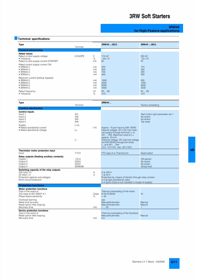
8122019 Arr Estado Solido
httpslidepdfcomreaderfullarr-estado-solido 1540
3RW Soft Starters
3RW44for High-Feature applications
Technical specifications
Type 3RW44 -BC3 3RW44 -BC4Terminal
Control electronics
Rated valuesRated control supply voltage A1A2PE V 115 AC 230 ACbull Tolerance -15+10 -15+10Rated control supply current STANDBY mA 30 20
Rated control supply current ONbull 3RW44 2 mA 300 170bull 3RW44 3 mA 500 250bull 3RW44 4 mA 750 400bull 3RW44 5 mA 450 200
Maximum current (pickup bypass)bull 3RW44 2 mA 1000 500bull 3RW44 3 mA 2500 1250bull 3RW44 4 mA 6000 3000bull 3RW44 5 mA 4500 2500
Rated frequency Hz 50 60 50 60bull Tolerance plusmn10 plusmn10
Type 3RW44 Terminal Factory presetting
Control electronics
Control inputsInput 1 IN1 Start motor right parameter set 1Input 2 IN2 No actionInput 3 IN3 No actionInput 4 IN4 Trip reset
Supply L+L-bull Rated operational current mA Approx 10 per input to DIN 19240bull Rated operational voltage L+ Internal voltage 24 V DC from inter-
nal supply through terminal L+ toIN1 IN4 Maximum load at L+approx 55 mA
L- External voltage DC external voltage(to DIN19240) through terminals
L- and IN1 IN4(min 12 V DC max 30 V DC)
Thermistor motor protection inputInput T1T2 PTC type A or Thermoclick Deactivated
Relay outputs (floating auxiliary contacts)Output 1 1314 ON periodOutput 2 2324 No actionOutput 3 3334 No actionOutput 4 959698 Group fault
Switching capacity of the relay outputs230 VAC-15 A 3 at 240 V24 VDC-13 A 1 at 24 VProtection against overvoltages Protection by means of Varistor through relay contactShort-circuit protection 4 A gLgG operational class
6 A quick (fuse is not included in scope of supply)
Protective functions
Motor protection functionsTrips in the event of Thermal overloading of the motor
Trip class to IEC 60947-4-1 Class 510152030 10Phase failure sensitivity gt 40
Overload warning yesReset and recovery ManualAutomatic ManualReset option after tripping ManualAutomatic ManualRecovery time min 1 30 1
Device protection functionsTrips in the event of Thermal overloading of the thyristorsReset option after tripping ManualAutomatic ManualRecovery time min 05
8122019 Arr Estado Solido
httpslidepdfcomreaderfullarr-estado-solido 1640
3RW Soft Starters
3RW44for High-Feature applications
Type 3RW44 Factory presetting
Control times and parameters
Control timesClosing delay (with connected control voltage) ms lt 50Closing delay (automatic mode) ms lt 4000Recovery time (closing command in active ramp-down) ms lt 100
Mains failure bridging timeControl supply voltage ms 100
Mains failure response timeLoad current circuit ms 100
Reclosing lockout after overload tripMotor protection trip min 1 30 1Device protection trip s 30
Setting options for startingVoltage ramp for starting voltage 20 100 30Torque control for starting torque 20 100 50Torque control for limit torque 20 200 150
Starting time s 0 360 20Maximum starting time s 1 1000 DeactivatedCurrent limit value 125 550 450
Breakaway voltage 40 100 80Breakaway time s 0 2 DeactivatedMotor heat output 0 100 0
Creep mode LeftRight runningSpeed factor as function of rated speed (n = n rated factor) 3 21 7Creep torque (reference variable depends on the motor used but isalways smaller than the rated torque of the motor)
20 100 50
Setting options for ramp-downTorque control for stopping torque 10 100 10Ramp-down time s 0 360 10Dynamic braking torque 20 100 50DC braking torque 20 100 50
Operating indicationsTest voltageTest mains phasesReady to start
Start active
Motor runningRamp-down active
Warningserror signalsMains voltage missingLeading-edge phase error
Phase failurebull L1bull L2bull L3
Missing load phasebull T1bull T2bull T3
Failurebull Contact element 1 (thyristor)bull Contact element 2 (thyristor)bull Contact element 3 (thyristor)
Flash memory faulty
Supply voltagebull Below 75 bull Below 85 bull Over 110
Current unbalance exceededThermal motor model overload
Prewarning limit exceededbull Motor heatingbull Time-related trip reserve
Bypass elements defectiveMains voltage too high
Device not namedWrong naming versionCurrent range exceeded
Motor blocking ndash shutdownCurrent limit exceeded
Power section
bull Overheatedbull OvertemperatureEmergency active
8122019 Arr Estado Solido
httpslidepdfcomreaderfullarr-estado-solido 1740
3RW Soft Starters
3RW44for High-Feature applications
1) Parameter motor left possible only in conjunction with creep mode
Type 3RW44 Factory presetting
Control times and parameters
Warningserror signals (contd)Temperature sensorbull Overloadbull Open-circuitbull Short-circuit
Ground faultbull Detectedbull Shutdown
Connection abort in manual modeMax number of starts exceeded I e limit value overshootundershoot
Cooling timebull Motor activebull Switch block active
Heat sink sensorbull Open-circuitbull Short-circuit
Quick-stop functionSwitch block faulty I e class setting not permissible
Control inputsInput 1 Motor right parameter set 1Input 2 No actionInput 3 No actionInput 4 Trip reset
Parameterizing options for control inputs 1 4 No actionLocal manual modeEmergency startCreep speedQuick-stopTrip reset
Motor right parameter set 1Motor left parameter set 11) Motor right parameter set 2Motor left parameter set 21) Motor right parameter set 3Motor left parameter set 31)
Relay outputsOutput 1 ON periodOutput 2 No actionOutput 3 No actionOutput 4 Group fault
Parameterizing options for relay outputs 1 3 No actionPAA output 1PAA output 2
Input 1Input 2Input 3Input 4
Ramp-upOperationBypassRamp-downON periodCommand motor on
FanDC braking contactor
Group warningGroup faultBus faultDevice error
Power onReady to start
Motor temperature sensors Deactivated DeactivatedThermoclickPTC type A
8122019 Arr Estado Solido
httpslidepdfcomreaderfullarr-estado-solido 1840
3RW Soft Starters
3RW44for High-Feature applications
1) Current limit on soft starter set to 350 I M
2) For intermittent duty S4 with ON period = 70 T u = 40 degC stand-aloneinstallation vertical The quoted operating frequencies do not apply forautomatic mode
3) Maximum adjustable rated motor current I M dependent on CLASS setting
Type 3RW44 -BC4 3RW44 -BC5 3RW44 -BC6
Power electronics
Rated operational voltage for inline circuit V 200 460 AC 400 600 AC 400 690 AC
Tolerance -15+10 -15+10 -15+10Rated operational voltage for inside-delta circuit V 200 460 AC 400 600 AC 400 600 ACTolerance -15+10 -15+10 -15+10
Rated frequency Hz 50 60Tolerance plusmn10
Continuous operation at 40 degC ( of I e) 115
Minimum load ( of set motor current I M) 8
Maximum conductor length between soft starter and motor m 200
Permissible installation height m 5000 (derating from 1000 see characteristics) higher on request
Permissible mounting position
Permissible ambient temperatureOperation degC 0 +60 (derating from +40)Storage degC -25 +80
Degree of protection IP00
Type 3RW44 22 3RW44 23 3RW44 24 3RW44 25 3RW44 26 3RW44 27
Power electronics
Rated operational current I e 29 36 47 57 77 93
Load rating with rated operational current I ebull Acc to IEC and ULCSA for individual mounting
at 405060 degC AC-53a A 292623 363229 474237 575145 776859 938272
Smallest adjustable rated motor current I Mfor the motor overload protection
A 5 7 9 11 15 18
Power lossbull In operation after completed ramp-up with uninterrupted rated
operational current (40 degC) approx W 8 10 32 36 45 55bull During starting with current limit set to 350 I M (40 degC) W 400 470 600 725 940 1160
Permissible rated motor current and starts per hour
bull Normal starting (Class 5)- Rated motor current I M
1) starting time 5 s A 29 36 47 57 77 93- Starts per hour2) 1h 41 34 41 41 41 41
- Rated motor current I M1)3) starting time 10 s A 29 36 47 57 77 93
- Starts per hour2) 1h 20 15 20 20 20 20
bull Normal starting (Class 10)- Rated motor current I M
1) starting time 10 s A 29 36 47 57 77 93- Starts per hour2) 1h 20 15 20 20 20 20
- Rated motor current I M1)3) starting time 20 s A 29 36 47 57 77 93
- Starts per hour2) 1h 10 6 10 10 8 8
bull Normal starting (Class 15)- Rated motor current I M
1) starting time 15 s A 29 36 47 57 77 93- Starts per hour2) 1h 13 9 13 13 13 13
- Rated motor current I M1)3) starting time 30 s A 29 36 47 57 77 93
- Starts per hour2) 1h 6 4 6 6 6 6
bull For heavy starting (Class 20)- Rated motor current I M
1) starting time 20 s A 29 36 47 57 73 88- Starts per hour2) 1h 10 6 10 10 10 10
- Rated motor current I M1)3) starting time 40 s A 29 36 47 57 73 88
- Starts per hour2) 1h 4 2 4 5 18 08
bull For very heavy starting (Class 30)- Rated motor current I M
1) starting time 30 s A 29 36 44 57 65 77- Starts per hour2) 1h 6 4 6 6 6 6
- Rated motor current I M1)3) starting time 60 s A 29 36 44 57 65 77
- Starts per hour2) 1h 18 08 33 15 2 1
8122019 Arr Estado Solido
httpslidepdfcomreaderfullarr-estado-solido 1940
3RW Soft Starters
3RW44for High-Feature applications
1) Current limit on soft starter set to 350 I M
2) For intermittent duty S4 with ON period = 70 T u = 40 degC stand-aloneinstallation vertical The quoted operating frequencies do not apply forautomatic mode
3) Maximum adjustable rated motor current I M dependent on CLASS setting
Type 3RW44 34 3RW44 35 3RW44 36
Power electronics
Rated operational current I e 113 134 162
Load rating with rated operational current I ebull Acc to IEC and ULCSA for individual mounting AC-53a
- at 40 degC A 113 134 162- at 50 degC A 100 117 145- at 60 degC A 88 100 125
Smallest adjustable rated motor current I Mfor the motor overload protection
A 22 26 32
Power lossbull In operation after completed ramp-up with uninterrupted rated
operational current (40 degC) approx W 64 76 95bull During starting with current limit set to 350 I M (40 degC) W 1350 1700 2460
Permissible rated motor current and starts per hour
bull Normal starting (Class 5)- Rated motor current I M
1) starting time 5 s A 113 134 162- Starts per hour2) 1h 41 39 41
- Rated motor current I M1)3) starting time 10 s A 113 134 162
- Starts per hour2) 1h 20 15 20
bull Normal starting (Class 10)- Rated motor current I M
1) starting time 10 s A 113 134 162- Starts per hour2) 1h 20 15 20
- Rated motor current I M1)3) starting time 20 s A 113 134 162
- Starts per hour2) 1h 9 6 7
bull Normal starting (Class 15)- Rated motor current I M
1) starting time 15 s A 113 134 162- Starts per hour2) 1h 13 9 12
- Rated motor current I M1)3) starting time 30 s A 113 134 162
- Starts per hour2) 1h 6 6 1
bull For heavy starting (Class 20)- Rated motor current I M
1) starting time 20 s A 106 125 147- Starts per hour2) 1h 9 9 10
- Rated motor current I M1)3) starting time 40 s A 106 125 147
- Starts per hour2) 1h 15 2 1
bull For very heavy starting (Class 30)- Rated motor current I M
1) starting time 30 s A 91 110 120
- Starts per hour2) 1h 6 6 6- Rated motor current I M
1)3) starting time 60 s A 91 110 120- Starts per hour2) 1h 2 2 2
8122019 Arr Estado Solido
httpslidepdfcomreaderfullarr-estado-solido 2040
3RW Soft Starters
3RW44for High-Feature applications
1) Current limit on soft starter set to 350 I M
2) For intermittent duty S4 with ON period = 70 T u = 40 degC stand-aloneinstallation vertical The quoted operating frequencies do not apply forautomatic mode
3) Maximum adjustable rated motor current I M dependent on CLASS setting
Type 3RW44 43 3RW44 44 3RW44 45 3RW44 46 3RW44 47
Power electronics
Rated operational current I e 203 250 313 356 432
Load rating with rated operational current I ebull Acc to IEC and ULCSA for individual mounting AC-53a
- at 40 degC A 203 250 313 356 432- at 50 degC A 180 215 280 315 385- at 60 degC A 156 185 250 280 335
Smallest adjustable rated motor current I Mfor the motor overload protection
A 40 50 62 71 86
Power lossbull In operation after completed ramp-up with uninterrupted rated
operational current (40 degC) approx W 89 110 145 174 232bull During starting with current limit set to 350 I M (40 degC) W 3350 4000 4470 5350 5860
Permissible rated motor current and starts per hour
bull Normal starting (Class 5)- Rated motor current I M
1) starting time 5 s A 203 250 313 356 432- Starts per hour2) 1h 41 41 41 41 39
- Rated motor current I M1)3) starting time 10 s A 203 250 313 356 432
- Starts per hour2) 1h 20 20 19 17 16
bull Normal starting (Class 10)- Rated motor current I M
1) starting time 10 s A 203 250 313 356 432- Starts per hour2) 1h 20 20 19 17 16
- Rated motor current I M1)3) starting time 20 s A 203 250 313 356 432
- Starts per hour2) 1h 9 10 6 4 5
bull Normal starting (Class 15)- Rated motor current I M
1) starting time 15 s A 203 240 313 325 402- Starts per hour2) 1h 13 13 10 13 11
- Rated motor current I M1)3) starting time 30 s A 203 240 313 325 402
- Starts per hour2) 1h 3 6 1 2 1
bull For heavy starting (Class 20)- Rated motor current I M
1) starting time 20 s A 195 215 275 285 356- Starts per hour2) 1h 10 10 10 10 10
- Rated motor current I M1)3) starting time 40 s A 195 215 275 285 356
- Starts per hour2) 1h 1 5 1 3 1
bull For very heavy starting (Class 30)- Rated motor current I M
1) starting time 30 s A 162 180 220 240 285
- Starts per hour2) 1h 6 6 6 6 6- Rated motor current I M
1)3) starting time 60 s A 162 180 220 240 285- Starts per hour2) 1h 3 3 3 2 1
8122019 Arr Estado Solido
httpslidepdfcomreaderfullarr-estado-solido 2140
3RW Soft Starters
3RW44for High-Feature applications
1) Current limit on soft starter set to 350 I M
2) For intermittent duty S4 with ON period = 70 T u = 40 degC stand-aloneinstallation vertical The quoted operating frequencies do not apply forautomatic mode
3) Maximum adjustable rated motor current I M dependent on CLASS setting
Type 3RW44 53 3RW44 54 3RW44 55 3RW44 56 3RW44 57 3RW44 58
Power electronics
Rated operational current I e 551 615 693 780 880 970
Load rating with rated operational current I ebull Acc to IEC and ULCSA for individual mounting AC-53a
- at 40 degC A 551 615 693 780 880 970- at 50 degC A 494 551 615 693 780 850- at 60 degC A 438 489 551 615 693 760
Smallest adjustable rated motor current I Mfor the motor overload protection
A 110 123 138 156 176 194
Power lossbull In operation after completed ramp-up with uninterrupted rated
operational current (40 degC) approx W 159 186 220 214 250 270bull During starting with current limit set to 350 I M (40 degC) W 7020 8100 9500 11100 13100 15000
Permissible rated motor current and starts per hour
bull Normal starting (Class 5)- Rated motor current I M
1) starting time 5 s A 551 615 693 780 880 970- Starts per hour2) 1h 41 41 37 33 22 17
- Rated motor current I M1)3) starting time 10 s A 551 615 693 780 880 970
- Starts per hour2) 1h 20 20 16 13 8 5
bull Normal starting (Class 10)- Rated motor current I M
1) starting time 10 s A 551 615 693 780 880 970- Starts per hour2) 1h 20 20 16 13 8 5
- Rated motor current I M1)3) starting time 20 s A 551 615 693 780 880 970
- Starts per hour2) 1h 10 9 6 4 03 03
bull Normal starting (Class 15)- Rated motor current I M
1) starting time 15 s A 551 615 666 723 780 821- Starts per hour2) 1h 13 13 11 9 8 8
- Rated motor current I M1)3) starting time 30 s A 551 615 666 723 780 821
- Starts per hour2) 1h 6 4 3 1 04 05
bull For heavy starting (Class 20)- Rated motor current I M
1) starting time 20 s A 551 591 633 670 710 740- Starts per hour2) 1h 10 10 7 8 8 9
- Rated motor current I M1)3) starting time 40 s A 551 591 633 670 710 740
- Starts per hour2) 1h 4 2 1 1 04 1
bull For very heavy starting (Class 30)- Rated motor current I M
1) starting time 30 s A 500 525 551 575 600 630
- Starts per hour2) 1h 6 6 6 6 6 6- Rated motor current I M
1)3) starting time 60 s A 500 525 551 575 600 630- Starts per hour2) 1h 2 1 1 1 15 1
8122019 Arr Estado Solido
httpslidepdfcomreaderfullarr-estado-solido 2240
3RW Soft Starters
3RW44for High-Feature applications
1) When connecting cable lugs to DIN 46235 use 3RT19 56-4EA1 terminalcover for conductor cross-sections from 95 mmsup2 to ensure phase spacing
2) When connecting cable lugs to DIN 46234 the 3RT19 66-4EA1 terminalcover must be used for conductor cross-sections of 240 mmsup2 and more aswell as DIN 46235 for conductor cross-sections of 185 mmsup2 and more tokeep the phase clearance
Type 3RW44 2 3RW44 3 3RW44 4 3RW44 5
Conductor cross-sections
Screw
terminals
Main conductors
with box terminal 3RT19 55-4G (55 kW) 3RT19 66-4G
Front clampingpoint connected
bull Finely stranded with end sleeve mm2 16 70 70 240bull Finely stranded without end sleeve mm2 16 70 70 240bull Stranded mm2 16 70 95 300
bull Ribbon cable conductors(number x width x thickness)
mm min 3 x 9 x 08max 6 x 155 x 08
min 6 x 9 x 08max 20 x 24 x 05
bull AWG conductors solid or stranded AWG 6 20 30 600 kcmil
Rear clamping pointconnected
bull Finely stranded with end sleeve mm2 16 70 120 185bull Finely stranded without end sleeve mm2 16 70 120 185bull Stranded mm2 16 70 120 240
bull Ribbon cable conductors(number x width x thickness)
mm min 3 x 9 x 08max 6 x 155 x 08
min 6 x 9 x 08max 20 x 24 x 05
bull AWG conductors solid or stranded AWG 6 20 250 500 kcmil
Both clamping
points connected
bull Finely stranded with end sleeve mm2 max 1 x 50 1 x 70 min 2 x 50 max 2 x 185
bull Finely stranded without end sleeve mm2 max 1 x 50 1 x 70 min 2 x 50 max 2 x 185bull Stranded mm2 max 2 x 70 max 2 x 70 max 2 x 240
bull Ribbon cable conductors(number x width x thickness)
mm max 2 x (6 x 155 x 08) max 2 x (20 x 24 x 05)
bull AWG conductors solid or stranded AWG max 2 x 10 min 2 x 20max 2 x 500 kcmil
bull Terminal screws M10 (hexagon socket AF4) M12 (hexagon socket AF5)- Pickup torque 10 12 20 22
90 110 180 195
Screwterminals
Main conductors
with box terminal 3RT19 56-4G
Front or rear clamp-ing point connected
bull Finely stranded with end sleeve mm2 16 120bull Finely stranded without end sleeve mm2 16 120bull Stranded mm2 16 120
bull Ribbon cable conductors(number x width x thickness)
mm min 3 x 9 x 08max 6 x 155 x 08
bull AWG conductors solid or stranded AWG 6 250 kcmil
Both clampingpoints connected
bull Finely stranded with end sleeve mm2 max 1 x 95 1 x 120bull Finely stranded without end sleeve mm2 max 1 x 95 1 x 120bull Stranded mm2 max 2 x 120
bull Ribbon cable conductors(number x width x thickness)
mm max 2 x (10 x 155 x 08)
bull AWG conductors solid or stranded AWG max 2 x 30
Screwterminals
Main conductors
Without box terminalrail connection
bull Finely stranded with cable lug mm2 16 951) 50 2402) 50 2402)
bull Stranded with cable lug mm2 25 1201) 70 2402) 70 2402)
bull AWG conductors solid or stranded AWG 4 250 kcmil 20 500 kcmil 10 500 kcmil
bull Connecting bar (max width) mm 17 25 60
bull Terminal screws M8 x 25 (AF13) M10 x 30 (AF17) M12 x 40- Pickup torque NM 10 14 14 24 20 35lbin 89 124 124 210 177 310
8122019 Arr Estado Solido
httpslidepdfcomreaderfullarr-estado-solido 2340
3RW Soft Starters
3RW44for High-Feature applications
Soft starters Type 3RW44
Conductor cross-sections
Auxiliary conductors (1 or 2 conductors can be connected)
Screw terminals
bull Solid mm2 2 x 05 25bull Finely stranded with end sleeve mm2 2 x 05 15
bull AWG cables- Solid or stranded AWG 2 x 20 14- Finely stranded with end sleeve AWG 2 x 20 16
bull Terminal screws- Pickup torque NM 07 09
lbin 7 8
Spring-loaded terminals
bull Solid mm2 2 x 025 25bull Finely stranded with end sleeve mm2 2 x 025 15bull AWG conductors solid or stranded AWG 2 x 24 14
Standard Parameters
Electromagnetic compatibility acc to EN 60947-4-2
EMC interference immunityElectrostatic discharge (ESD) EN 61000-4-2 plusmn4 kV contact discharge plusmn8 kV air discharge
Electromagnetic RF fields EN 61000-4-3 Frequency range 80 1000 MHz with 80 at 1 kHzDegree of severity 3 10 Vm
Conducted RF interference EN 61000-4-6 Frequency range 150 kHz 80 MHz with 80 at 1 kHzInterference 10 V
RF voltages and RF currents on conductorsBurst EN 61000-4-4 plusmn2 kV5 kHzSurge EN 61000-4-5 plusmn1 kV line to line
plusmn2 kV line to ground
EMC interference emission
EMC interference field strength EN55011 Limit value of Class A at 30 1000 MHz
Radio interference voltage EN55011 Limit value of Class A at 015 30 MHz
Is an RI suppression filter necessary
Degree of noise suppression A (industrial applications) no
8122019 Arr Estado Solido
httpslidepdfcomreaderfullarr-estado-solido 2440
3RW Soft Starters
3RW44for High-Feature applications
Fuse assignment
The coordination type to which the motor feeder with soft starteris mounted depends on the application-specific requirements
Normally fuseless mounting (combination of motor starter pro-tector and soft starter) is sufficient If type 2 coordination is to befulfilled semiconductor fuses must be fitted in the motor feeder
1) The rated motor current must be considered when selecting the devices
2) The types of coordination are explained in more detail in theTechnical information LV 1 T under ndash Fuseless Load Feeders
Inline circuit fuseless version
Soft starters Motor starter protectorscircuit-breakers1)
Rated current 440 V +10 Rated currentG1 Q1Type A Type A
Type of coordination 12) 3RW44 22 3RW44 27 I q = 32 kA 3RW44 34 and 3RW44 35 I q = 16 kA 3RW44 36 3RW44 57 I q = 65 kA
3RW44 22 29 3RV10 42-4HA10 503RW44 23 36 3RV10 42-4JA10 633RW44 24 47 3RV10 42-4KA10 75
3RW44 25 57 3RV10 42-4LA10 903RW44 26 77 3RV10 42-4MA10 1003RW44 27 93 3RV10 42-4MA10 100
3RW44 34 113 3VL17 16-2DD36 1603RW44 35 134 3VL17 16-2DD36 1603RW44 36 162 3VL37 25-2DC36 250
3RW44 43 203 3VL47 31-3DC36 3153RW44 44 250 3VL47 31-3DC36 3153RW44 45 313 3VL47 40-3DC36 400
3RW44 46 356 3VL47 40-3DC36 4003RW44 47 432 3VL57 50-3DC36 500
3RW44 53 551 3VL67 80-3DE36 8003RW44 54 615 3VL67 80-3DE36 8003RW44 55 693 3VL67 80-3DE36 800
3RW44 56 780 3VL77 10-3AB36 10003RW44 57 880 3VL77 10-3AB36 10003RW44 58 970 3VL77 12-3AB36 1200
8122019 Arr Estado Solido
httpslidepdfcomreaderfullarr-estado-solido 2540
3RW Soft Starters
3RW44for High-Feature applications
1) If the ramp-down function Combined braking is selected no brakingcontactor is requiredIf the ramp-down function DC braking is selected a braking contactormust also be used (see table for type)For applications with large centrifugal masses (J Load gt J Motor) werecommend the function DC braking
2) Additional auxiliary relay K4LZXRT4A4T30(3RW44 soft starter with rated control supply voltage 230 V AC)LZXRT4A4S15(3RW44 soft starter with rated control supply voltage 115 V AC)
3) The types of coordination are explained in more detail in theTechnical information LV 1 T under ndash Fuseless Load Feeders
Inline circuit fused version (line protection only)
Soft starters Line protections Line contactorsup to 400 V
Braking contactors1)2)
Rated current 690 V +5 Rated current Size (optional) (for typical circuit see page 633)G1 F1 K1 K2 K3Type A Type A Type Type Type
Type of coordination 13) I q = 65 kA
3RW44 22 29 3NA3 820-6 50 00 3RT10 34 3RT15 26 --3RW44 23 36 3NA3 822-6 63 00 3RT10 35 3RT15 26 --
3RW44 24 47 3NA3 824-6 80 00 3RT10 36 3RT15 35 --3RW44 25 57 3NA3 830-6 100 00 3RT10 44 3RT15 35 --3RW44 26 77 3NA3 132-6 125 1 3RT10 45 3RT10 24 3RT10 353RW44 27 93 3NA3 136-6 160 1 3RT10 46 3RT10 25 3RT10 36
3RW44 34 113 3NA3 244-6 250 2 3RT10 54 3RT10 34 3RT10 443RW44 35 134 3NA3 244-6 250 2 3RT10 55 3RT10 36 3RT10 453RW44 36 162 3NA3 365-6 500 3 3RT10 56 3RT10 44 3RT10 45
3RW44 43 203 2 x 3NA3 354-6 2 x 355 3 3RT10 64 3RT10 44 3RT10 543RW44 44 250 2 x 3NA3 354-6 2 x 355 3 3RT10 65 3RT10 44 3RT10 553RW44 45 313 2 x 3NA3 365-6 2 x 500 3 3RT10 75 3RT10 54 3RT10 56
3RW44 46 356 2 x 3NA3 365-6 2 x 500 3 3RT10 75 3RT10 54 3RT10 563RW44 47 432 2 x 3NA3 365-6 2 x 500 3 3RT10 76 3RT10 55 3RT10 64
3RW44 53 551 2 x 3NA3 365-6 2 x 500 3 3TF68 44-0CM7 3TF68 44-0CM7 3TF68 44-0CM73RW44 54 615 2 x 3NA3 365-6 2 x 500 3 3TF68 44-0CM7 3TF68 44-0CM7 3TF68 44-0CM73RW44 55 693 2 x 3NA3 365-6 2 x 500 3 3TF69 44-0CM7 3TF69 44-0CM7 3TF69 44-0CM7
3RW44 56 780 2 x 3NA3 365-6 2 x 500 3 3TF69 44-0CM7 3TF69 44-0CM7 3TF69 44-0CM73RW44 57 880 2 x 3NA3 365-6 2 x 500 3 2 x 3TF69 44-0CM7 2 x 3TF69 44-0CM7 2 x 3TF69 44-0CM7
3RW44 58 970 3 x 3NA3 365-6 3 x 500 3
8122019 Arr Estado Solido
httpslidepdfcomreaderfullarr-estado-solido 2640
3RW Soft Starters
3RW44for High-Feature applications
1) If the ramp-down function Combined braking is selected no brakingcontactor is requiredIf the ramp-down function DC braking is selected a braking contactormust also be used (see table for type)For applications with large centrifugal masses (J Load gt J Motor) werecommend the function DC braking
2) Additional auxiliary relay K4LZXRT4A4T30(3RW44 soft starter with rated control supply voltage 230 V AC)LZXRT4A4S15(3RW44 soft starter with rated control supply voltage 115 V AC)
3) The types of coordination are explained in more detail in theTechnical information LV 1 T under ndash Fuseless Load Feeders
Inline circuit fused version with 3NE1 SITOR all-range fuse (semiconductor and line protection)
Soft starters All-range fuses Line contactors upto 400 V
Braking contactors1)2)
Ratedcurrent
Rated current Voltage Size (optional) (for typical circuit see page 633)
G1 Frsquo1 K1 K2 K3Type A Type A V Type Type Type
Type of coordination 23) I q = 65 kA
3RW44 22 29 3NE1 020-2 80 690 +5 00 3RT10 34 3RT15 26 --
3RW44 23 36 3NE1 020-2 80 690 +5 00 3RT10 35 3RT15 26 --3RW44 24 47 3NE1 021-2 100 690 +5 00 3RT10 36 3RT15 35 --
3RW44 25 57 3NE1 022-2 125 690 +5 00 3RT10 44 3RT15 35 --3RW44 26 77 3NE1 022-2 125 690 +5 00 3RT10 45 3RT10 24 3RT10 353RW44 27 93 3NE1 024-2 160 690 +5 1 3RT10 46 3RT10 25 3RT10 36
3RW44 34 113 3NE1 225-2 200 690 +5 1 3RT10 54 3RT10 34 3RT10 443RW44 35 134 3NE1 227-2 250 690 +5 1 3RT10 55 3RT10 36 3RT10 453RW44 36 162 3NE1 227-2 250 690 +5 1 3RT10 56 3RT10 44 3RT10 45
3RW44 43 203 3NE1 230-2 315 600 +10 1 3RT10 64 3RT10 44 3RT10 543RW44 44 250 3NE1 331-2 350 460 +10 2 3RT10 65 3RT10 44 3RT10 553RW44 45 313 3NE1 333-2 450 690 +5 2 3RT10 75 3RT10 54 3RT10 56
3RW44 46 356 3NE1 334-2 500 690 +5 2 3RT10 75 3RT10 54 3RT10 563RW44 47 432 3NE1 435-2 560 690 +5 3 3RT10 76 3RT10 55 3RT10 64
3RW44 53 551 2 x 3NE1 334-2 500 690 +10 2 3TF68 44-0CM7 3TF68 44-0CM7 3TF68 44-0CM73RW44 54 615 2 x 3NE1 334-2 500 690 +10 2 3TF68 44-0CM7 3TF68 44-0CM7 3TF68 44-0CM73RW44 55 693 2 x 3NE1 334-2 500 690 +10 2 3TF69 44-0CM7 3TF69 44-0CM7 3TF69 44-0CM7
3RW44 56 780 2 x 3NE1 435-2 560 690 +10 3 3TF69 44-0CM7 3TF69 44-0CM7 3TF69 44-0CM7
3RW44 57 880 2 x 3NE1 435-2 560 690 +10 3 2 x 3TF69 44-0CM7 2 x 3TF69 44-0CM7 2 x 3TF69 44-0CM73RW44 58 970 2 x 3NE1 435-2 560 690 +10 3
8122019 Arr Estado Solido
httpslidepdfcomreaderfullarr-estado-solido 2740
3RW Soft Starters
3RW44for High-Feature applications
1) If the ramp-down function Combined braking is selected no brakingcontactor is requiredIf the ramp-down function DC braking is selected a braking contactor
must also be used (see table for type)For applications with large centrifugal masses (J Load gt J Motor) werecommend the function DC braking
2) Additional auxiliary relay K4LZXRT4A4T30(3RW44 soft starter with rated control supply voltage 230 V AC)
LZXRT4A4S15(3RW44 soft starter with rated control supply voltage 115 V AC)
3) The types of coordination are explained in more detail in theTechnical information LV 1 T under ndash Fuseless Load Feeders
Inline circuit fused version with 3NE or 3NC SITOR semiconductor fuse(semiconductor protection by fuse lead and overload protection by circuit-breaker)
Soft starters Semiconductor fuses minimum Semiconductor fuses maximum Semiconductor fuses (cylinder)
Ratedcurrent
Rated current Size Rated current Size Rated current Size
G1 F3 F3 F3Type A Type A Type A Type A
Type of coordination 23) I q = 65 kA
3RW44 22 29 3NE4 120 80 0 3NE4 121 100 0 3NC2 280 80 22 x 58
3RW44 23 36 3NE4 121 100 0 3NE4 122 125 0 3NC2 200 100 22 x 583RW44 24 47 3NE4 121 100 0 3NE4 122 125 0 3NC2 200 100 22 x 58
3RW44 25 57 3NE4 122 125 0 3NE4 124 160 03RW44 26 77 3NE4 124 160 0 3NE4 124 160 03RW44 27 93 3NE3 224 160 1 3NE3 333 450 2
3RW44 34 113 3NE3 225 200 1 3NE3 335 560 23RW44 35 134 3NE3 225 200 1 3NE3 335 560 23RW44 36 162 3NE3 227 250 1 3NE3 333 450 2
3RW44 43 203 3NE3 230-0B 315 1 3NE3 333 450 23RW44 44 250 3NE3 230-0B 315 1 3NE3 333 450 23RW44 45 313 3NE3 233 450 1 3NE3 336 630 2
3RW44 46 356 3NE3 333 450 2 3NE3 336 630 23RW44 47 432 3NE3 335 560 2 3NE3 338-8 800 2
3RW44 53 551 2 x 3NE3 335 560 2 3 x 3NE3 334-0B 500 23RW44 54 615 2 x 3NE3 335 560 2 3 x 3NE3 334-0B 500 23RW44 55 693 2 x 3NE3 335 560 2 3 x 3NE3 334-0B 500 2
3RW44 56 780 2 x 3NE3 336 630 2 2 x 3NE3 340-8 900 2
3RW44 57 880 2 x 3NE3 336 630 2 2 x 3NE3 340-8 900 23RW44 58 970 2 x 3NE3 336 630 2 2 x 3NE3 340-8 900 2
Soft starters Line contactorsup to 400 V
Braking contactors1)2) Motor starter protectors circuit-breakers
Max line protection
Ratedcurrent
(optional) (for typical circuit see page 633) 440 V +10 Rated current 690 V +5 Rated current Size
G1 K1 Q1 F1Type A Type Type Type Type A Type A
Type of coordination 23) 3RW44 22 3RW44 27 I q = 32 kA 3RW44 34 and 3RW44 35 I q = 16 kA 3RW44 36 3RW44 57 I q = 65 kA
3RW44 22 29 3RT10 34 3RT15 26 -- 3RV10 41-4HA10 50 3NA3 820-6 50 003RW44 23 36 3RT10 35 3RT15 26 -- 3RV10 41-4JA10 63 3NA3 822-6 63 003RW44 24 47 3RT10 36 3RT15 35 -- 3RV10 41-4KA10 75 3NA3 824-6 80 00
3RW44 25 57 3RT10 44 3RT15 35 -- 3RV10 41-4LA10 90 3NA3 830-6 100 003RW44 26 77 3RT10 45 3RT10 24 3RT10 35 3RV10 41-4MA10 100 3NA3 132-6 125 13RW44 27 93 3RT10 46 3RT10 25 3RT10 36 3RV10 41-4MA10 100 3NA3 136-6 160 1
3RW44 34 113 3RT10 54 3RT10 34 3RT10 44 3VL17 16-1DD36 160 3NA3 244-6 250 2
3RW44 35 134 3RT10 55 3RT10 36 3RT10 45 3VL17 16-1DD36 160 3NA3 244-6 250 23RW44 36 162 3RT10 56 3RT10 44 3RT10 45 3VL37 25-1DC36 250 3NA3 365-6 500 3
3RW44 43 203 3RT10 64 3RT10 44 3RT10 54 3VL47 31-1DC36 315 2 x 3NA3 354-6 2 x 355 33RW44 44 250 3RT10 65 3RT10 44 3RT10 55 3VL47 31-1DC36 315 2 x 3NA3 354-6 2 x 355 33RW44 45 313 3RT10 75 3RT10 54 3RT10 56 3VL47 40-1DC36 400 2 x 3NA3 365-6 2 x 500 3
3RW44 46 356 3RT10 75 3RT10 54 3RT10 56 3VL47 40-1DC36 400 2 x 3NA3 365-6 2 x 500 33RW44 47 432 3RT10 76 3RT10 55 3RT10 64 3VL57 50-1DC36 500 2 x 3NA3 365-6 2 x 500 3
3RW44 53 551 3TF68 44-0CM7 3TF68 44-0CM7 3TF68 44-0CM7 3VL67 80-1AB36 800 2 x 3NA3 365-6 2 x 500 33RW44 54 615 3TF68 44-0CM7 3TF68 44-0CM7 3TF68 44-0CM7 3VL67 80-1AB36 800 2 x 3NA3 365-6 2 x 500 33RW44 55 693 3TF69 44-0CM7 3TF69 44-0CM7 3TF69 44-0CM7 3VL67 80-1AB36 800 2 x 3NA3 365-6 2 x 500 3
3RW44 56 780 3TF69 44-0CM7 3TF69 44-0CM7 3TF69 44-0CM7 3VL77 10-1AB36 1000 2 x 3NA3 365-6 2 x 500 33RW44 57 880 2 x
3TF69 44-0CM72 x3TF69 44-0CM7
2 x3TF69 44-0CM7
3VL77 10-1AB36 1000 2 x 3NA3 365-6 2 x 500 3
3RW44 58 970 3VL77 12-1AB36 1200 3 x 3NA3 365-6 3 x 500 3
8122019 Arr Estado Solido
httpslidepdfcomreaderfullarr-estado-solido 2840
3RW Soft Starters
3RW44for High-Feature applications
1) The types of coordination are explained in more detail in theTechnical information LV 1 T under ndash Fuseless Load FeedersThe type of coordination 2 only refers to soft starters not to feeder compo-nents ( I q = 65 kA)
Inside-delta circuit fused version with 3NE or 3NC SITOR fuses(semiconductor protection by fuse lead and overload protection by circuit-breaker)
Soft starters Semiconductor fuses minimum Semiconductor fuses maximum Semiconductor fuses (cylinder)
Ratedcurrent
Rated current Size Rated current Size Rated current Size
G1 F3 F3 F3Type A Type A Type A Type A
Type of coordination 21)
3RW44 22 50 3NE4 120 80 0 3NE4 121 100 0 3NC2 280 80 22 x 58
3RW44 23 62 3NE4 121 100 0 3NE4 122 125 0 3NC2 200 100 22 x 583RW44 24 81 3NE4 121 100 0 3NE4 122 125 0 3NC2 200 100 22 x 58
3RW44 25 99 3NE4 122 125 0 3NE4 124 160 03RW44 26 133 3NE4 124 160 0 3NE4 124 160 03RW44 27 161 3NE3 224 160 1 3NE3 333 450 2
3RW44 34 196 3NE3 225 200 1 3NE3 335 560 23RW44 35 232 3NE3 225 200 1 3NE3 335 560 23RW44 36 281 3NE3 227 250 1 3NE3 333 450 2
3RW44 43 352 3NE3 230-0B 315 1 3NE3 333 450 23RW44 44 433 3NE3 230-0B 315 1 3NE3 333 450 23RW44 45 542 3NE3 233 450 1 3NE3 336 630 2
3RW44 46 617 3NE3 333 450 2 3NE3 336 630 23RW44 47 748 3NE3 335 560 2 3NE3 338-8 800 2
3RW44 53 954 2 x 3NE3 335 560 2 3 x 3NE3 334-0B 500 23RW44 54 1065 2 x 3NE3 335 560 2 3 x 3NE3 334-0B 500 23RW44 55 1200 2 x 3NE3 335 560 2 3 x 3NE3 334-0B 500 2
3RW44 56 1351 2 x 3NE3 336 630 2 2 x 3NE3 340-8 900 2
3RW44 57 1524 2 x 3NE3 336 630 2 3 x 3NE3 340-8 900 23RW44 58 1680 2 x 3NE3 336 630 2 3 x 3NE3 340-8 900 2
Soft starters Line contactorsup to 400 V
Motor starter protectors cirduit-breakers
Line protections
Ratedcurrent
(optional) 440 V +10 Rated current 690 V +5 Rated current Size
G1 K1 Q1 F1Type A Type Type A Type A
Type of coordination 21)
3RW44 22 50 3RT10 36-1AP04 3RV10 4-4KA10 75 3NA3 824-6 80 003RW44 23 62 3RT10 44-1AP04 3RV10 4-4LA10 90 3NA3 830-6 100 003RW44 24 81 3RT10 46-1AP04 3RV10 4-4MA10 100 3NA3 132-6 125 1
3RW44 25 99 3RT10 54-1AP36 3VL27 16-DC36 160 3NA3 136-6 160 13RW44 26 133 3RT10 55-6AP36 3VL27 16-DC36 160 3NA3 240-6 200 23RW44 27 161 3RT10 56-6AP36 3VL37 20-DC36 200 3NA3 244-6 250 2
3RW44 34 196 3RT10 64-6AP36 3VL37 25-DC36 250 3NA3 360-6 400 3
3RW44 35 232 3RT10 65-6AP36 3VL47 31-DC36 315 3NA3 360-6 400 33RW44 36 281 3RT10 66-6AP36 3VL47 40-DC36 400 2 x 3NA3 360-6 2 x 400 3
3RW44 43 352 3RT10 75-6AP36 3VL47 40-DC36 400 2 x 3NA3 365-6 2 x 500 33RW44 44 433 3RT10 76-6AP36 3VL57 50-DC36 500 2 x 3NA3 365-6 2 x 500 33RW44 45 542 3TF68 44-0CM7 3VL57 63-DC36 800 3 x 3NA3 365-6 3 x 500 3
3RW44 46 617 3TF68 44-0CM7 3VL67 80-AB36 800 3 x 3NA3 365-6 3 x 500 33RW44 47 748 3TF69 3VL67 80-AB36 1000 3 x 3NA3 365-6 3 x 500 3
3RW44 53 954 2 x 3TF68 44-0CM7 3VL77 10-AB36 1000 3 x 3NA3 365-6 3 x 500 33RW44 54 1065 2 x 3TF68 44-0CM7 3VL77 12-AB36 1250 3 x 3NA3 365-6 3 x 500 33RW44 55 1200 2 x 3TF69 44-0CM7 3VL87 16-AB36 1600 3 x 3NA3 365-6 3 x 500 3
3RW44 56 1351 2 x 3TF69 44-0CM7 3VL87 16-AB36 1600 3 x 3NA3 372 3 x 630 33RW44 57 1524 2 x 3TF69 44-0CM7 3VL87 16-AB36 1600 3 x 3NA3 372 3 x 630 33RW44 58 1680 3WL12 20 2000 2 x 3NA3 480 2 x 1000 4
8122019 Arr Estado Solido
httpslidepdfcomreaderfullarr-estado-solido 2940
3RW Soft Starters
3RW44for High-Feature applications
Characteristic curves
Motor protection tripping characteristics for 3RW44(with symmetry)
Admissible mounting height
The admissible operational voltage is reduced to 460 V with a mountingheight of more than 2000 m
Motor protection characteristics for 3RW44(with phase unbalance)
e
2 4 6 101
Class 10 Class 15 Class 20
100
101
102
103
2
4
6
2
4
6
2
4
6
Class 5 Class 30
N S B 0
_ 0 1 5 0 0 a
[ s ]
x
T r i p p i n g t i m e
85
105
70
75
80
90
95
100
N S B 0
_ 0 1 7 0 4
0 1000 2000 3000 4000 5000 O p e r
a t i o n a
l r a
t e d c u r r e n
t I
i n
Mounting height in m
e
e
1001
Class 10 Class 15 Class 20
100
101
102
103
2
4
6
2
4
6
2
4
6
Class 5 Class 30
N S B 0
_ 0 1 7 0 6
[ s ]
x10
T r i p p
i n g
t i m e
8122019 Arr Estado Solido
httpslidepdfcomreaderfullarr-estado-solido 3040
3RW Soft Starters
3RW44for High-Feature applications
More information
Application examples for normal starting (Class 10)
Application examples for heavy starting (Class 20)
Application examples for very heavy starting (Class 30)
NoteThese tables present sample setting values and device sizesThey are intended only for the purposes of information and arenot binding The setting values depend on the application inquestion and must be optimized during commissioningThe soft starter dimensions should be checked where necessarywith the Win-Soft Starter software or with the help ofTechnical Assistance
Normal starting Class 10 (up to 20 s with 350 I n motor)The soft starter rating can be selected to be as high as the rating of the motor used
Application Conveyor belts Roller conveyors Compressors Small ventilators Pumps Hydraulic pumps
Starting parameters
bull Voltage ramp and currentlimiting- Starting voltage 70 60 50 30 30 30- Starting time s 10 10 10 10 10 10- Current limit value Deactivated Deactivated 4 x I M 4 x I M Deactivated Deactivated
bull Torque ramp- Starting torque 60 50 40 20 10 10- End torque 150 150 150 150 150 150- Starting time 10 10 10 10 10 10
bull Breakaway pulse Deactivated (0 ms) Deactivated (0 ms) Deactivated (0 ms) Deactivated (0 ms) Deactivated (0 ms) Deactivated (0 ms)
Ramp-down mode Smoothramp-down
Smoothramp-down
Free ramp-down Free ramp-down Pump ramp-down Free ramp-down
Heavy starting Class 20 (up to 40 s with 350 I n motor)The soft starter has to be selected one rating class higher than the motor used
Application Stirrers Centrifuges Milling machines
Starting parameters
bull Voltage ramp and currentlimiting- Starting voltage 30 30 30- Starting time s 30 30 30- Current limit value 4 x I M 4 x I M 4 x I M
bull Torque ramp- Starting torque 30 30 30- End torque 150 150 150- Starting time 30 30 30
bull Breakaway pulse Deactivated (0 ms) Deactivated (0 ms) Deactivated (0 ms)
Ramp-down mode Free ramp-down Free ramp-down Free ramp-down or DC braking
Very heavy starting Class 30 (up to 60 s with 350 I n motor)The soft starter has to be selected two rating classes higher than the motor used
Application Large ventilators Mills Breakers Circular sawbandsaws
Starting parameters
bull Voltage ramp and currentlimiting- Starting voltage 30 50 50 30- Starting time s 60 60 60 60- Current limit value 4 x I M 4 x I M 4 x I M 4 x I M
bull Torque ramp- Starting torque 20 50 50 20- End torque 150 150 150 150- Starting time 60 60 60 60
bull Breakaway pulse Deactivated (0 ms) 80 300 ms 80 300 ms Deactivated (0 ms)
Ramp-down mode Free ramp-down Free ramp-down Free ramp-down Free ramp-down
8122019 Arr Estado Solido
httpslidepdfcomreaderfullarr-estado-solido 3140
3RW Soft Starters
3RW44for High-Feature applications
Circuit concept
The SIRIUS 3RW44 soft starters can be operated in two differenttypes of circuit
bull Inline circuitThe controls for isolating and protecting the motor are simplyconnected in series with the soft starter The motor isconnected to the soft starter with three leads
bull Inside-delta circuitThe wiring is similar to that of wye-delta starters The phases ofthe soft starter are connected in series with the individual motorwindings The soft starter then only has to carry the phasecurrent amounting to about 58 of the rated motor current(conductor current)
Comparison of the types of circuit
Inline circuitRated current I e corresponds to the rated motor current I n3 leads to the motor
Inside-delta circuit
Rated current I e corresponds to approx 58 of the rated motorcurrent I n6 leads to the motor (as with wye-delta starters)
Which circuit
Using the inline circuit involves the lowest wiring complexityIf the soft starter to motor connections are long this contactsequence is preferableWith the inside-delta circuit there is double the wiring complexitybut a smaller size of device can be used at the same rating
Thanks to choosing the operational mode between the inline cir-cuit and inside-delta circuit the most favorable solution can al-ways be chosen
The braking function is possible only in the inline circuit
Configuration
The 3RW44 solid-state soft starters are designed for normalstarting In case of heavy starting or increased starting
frequency a larger device must be selectedFor long starting times it is recommended to have a PTC ther-mistor detector in the motor This also applies for the ramp-downmodes smooth ramp-down pump ramp-down and DC brakingbecause during the ramp-down time in these modes an addi-tional current loading applies in contrast to free ramp-down
In the motor feeder between the SIRIUS 3RW soft starter and themotor no capacitive elements are permitted (eg no reactive-power compensation equipment) In addition neither staticsystems for reactive-power compensation nor dynamic PFC(Power Factor Correction) must be operated in parallel duringstarting and ramp-down of the soft starter This is important toprevent faults arising on the compensation equipment andor thesoft starter
All elements of the main circuit (such as fuses and controls)
should be dimensioned for direct starting following the localshort-circuit conditions Fuses switching devices and overloadrelays must be ordered separately
The harmonic component load for starting currents must betaken into consideration for the selection of motor starterprotectors (selection of release)
NoteWhen switching on three-phase current motors voltage dropsnormally will occur with all types of starters (direct starters star- delta starters soft starters) On principle the feeding transformermust be configured such that when starting the motor thevoltage drop must occur within the admissible tolerance Whenthe feeding transformer is designed quite scarce the control vol- tage (being independent of the main voltage) should be sup- plied with a separate circuit in order to prevent the soft starterfrom switching off
Serial PC interface PROFIBUS DP communication moduleand parameterizing and operating software Soft Starter ES
The solid-state 3RW44 soft starters have a PC interface forcommunicating with the Soft Starter ES 2006 Smart software orto be connected to an external operating and monitoring mod-ule When using the optional communication module PROFIBUSthe 3RW44 soft starter can be connected to the PROFIBUS netand can communicate via GSD file or software Soft Starter ES2006 Professional
Manual for SIRIUS 3RW44
Besides containing all important information on planning com-missioning and servicing the manual also contains suggestedcircuits and the technical specifications for all devices
Win-Soft Starter selection and simulation program
With this software you can simulate and select all Siemens softstarters taking into account various parameters such as mainsproperties motor and load data and special applicationrequirements
The software is a valuable tool which makes complicatedlengthy manual calculations for determining the required softstarters superfluous
You can order the CD-ROM under the following order numberOrder No E20001-D1020-P302-V2-7400
More information can be found on the Internet athttpwwwsiemenscomsoftstarter
8122019 Arr Estado Solido
httpslidepdfcomreaderfullarr-estado-solido 3240
3RW Soft Starters
3RW44for High-Feature applications
SIRIUS soft starter training course (SD-SIRIUSO)
Siemens offers a 2-day training course on the SIRIUS solid-statesoft starters to keep customers and own personnel up-to-date on
configuring commissioning and servicing issuesPlease direct enquiries and applications to
AampD PT 4 (Trainings-Center Erlangen)Werner-von-Siemens-Str 65D-91052 ErlangenTelefon ++49 9131 729262Telefax ++49 9131 728172sibrainindustrysiemenscomhttp wwwsiemenscomsitrain
8122019 Arr Estado Solido
httpslidepdfcomreaderfullarr-estado-solido 3340
3RW Soft Starters
Project planning aids
Dimensional drawings
3RW44 2 3RW44 3 and 3RW44 4 for High-Feature applications
TypeDimension(mm)
a b c d e f g h I k l m n o p q
3RW44 2 180 170 37 11 167 100 240 270 180 148 75 153 7 184 66 M6 10 Nm
3RW44 3 180 170 37 17 167 100 240 270 180 148 75 153 7 198 9 M6 10 Nm
3RW44 4 210 210 48 25 190 140 269 298 205 166 16 166 9 230 11 M8 15 Nm
8122019 Arr Estado Solido
httpslidepdfcomreaderfullarr-estado-solido 3440
3RW Soft Starters
Project planning aids
3RW44 5 for High-Feature applications
147
173
195
118
N S B 0_
0 1 6 5 3
261
290
249
162
152
6 2 3
1 0 5
2 5 3
1 6 5
76
44
470
510
1
5 5
2
0Oslash14 40
6 3 8 5
5 9 0
8122019 Arr Estado Solido
httpslidepdfcomreaderfullarr-estado-solido 3540
3RW Soft Starters
Project planning aids
Schematics
1) Permissible values for main and control voltagesee Technical Specifications
3RW44 connection examples for main and control circuits
Main circuit Control circuitPossibility 1a Possibility 1Inline circuit with circuit-breaker and SITOR fuse(semiconductor protection only)
Control by pushbutton
Main circuit
Possibility 1b Possibility 1cInline circuit with full-rangeprotection (line andsemiconductor protection)
Inline circuit with line andSITOR fuse(semiconductor protection only)
Q1
L3L2L1
G1
F3
T1 T2 T3
M1
N S B 0_
0 1 4 9 0 a
L1 L2 L3
V1U1 W1
MPE 3~
3NPE 400 V AC 50 Hz
(optionalsemiconductorprotection fuse)
13 14 23 24 33 34 95 9896 +
T1 T2IN4IN3IN2IN1L-L+A1
A2
NPE
PE
G1
F2
NSB0_01494a
S t a r t
S 2
R e s e t S
3
StopS1
L1
On periodGrouperror
N o a c t i o n
N o a c t i o n
Noaction
PTC type Aor
Thermoclick
Noaction
1NPE 230 V AC 50 Hz
M o t o r o
n r i g h t
P S
1
1)
8122019 Arr Estado Solido
httpslidepdfcomreaderfullarr-estado-solido 3640
3RW Soft Starters
Project planning aids
1) Permissible values for main and control voltagesee Technical Specifications
2) Caution Risk of restartingThe start command (eg from the PLC) must be reset prior to a resetcommand because a new automatic restart will take place automaticallyif a start command is active after the reset command This appliesespecially in case of motor protection trippingFor safety reasons we recommend incorporating the group error output(terminals 95 and 96) in the controller
Main circuit Control circuit
Possibility 2 Possibility 2Inline circuit with main contactor Control of a main contactor and control by means of PLC
Q1
L3L2L1
G1
K1
F3
L1 L2 L3
T1 T2 T3
M1
N S B 0_
0 1 4 9 5 a
V1U1 W1
MPE 3~
1)
(optionalsemiconductorprotection)
(optional linecontactor if floatingswitching of themotor is planned)
3NPE 400 V AC 50 Hz
13 14 23 24 33 34 95 9896+
T1 T2IN4IN3IN2IN1L-L+A1
A2
NPE
PE
G1
K1NSB0_01496a
F2+24 V DC
M
L1 1NPE AC 230 V 50 Hz1)
Switch-on duration
M o t o r r i g h t
T r i p R e s e t
PLC outputs PLC inputs
N o a c t i o n
N o a c t i o n
No action No action
Group error
PTC type A Thermoclick
(optional line contactorif floating switchingof the motor is planned)
P S 1
ResetStart 2)
8122019 Arr Estado Solido
httpslidepdfcomreaderfullarr-estado-solido 3740
3RW Soft Starters
Project planning aids
1) Permissible values for main and control voltagesee Technical Specifications
2) Caution Risk of restartingThe start command (eg from the PLC) must be reset prior to a resetcommand because a new automatic restart will take place automaticallyif a start command is active after the reset command This applies espe-cially in case of motor protection trippingFor safety reasons we recommend incorporating the group error output(terminals 95 and 96) in the controller
3) If the ramp-down function Combined braking is selected no brakingcontactor is requiredIf the ramp-down function DC braking is selected a braking contactormust be used in addition Type see Fuse Coordination (inline circuit) onpages 621 to 623For applications with large centrifugal masses (J Load gt J Motor) werecommend the function DC brakingThe output 2 must be switched over to DC braking contactor
4) Auxiliary relay K4 egLZXRT4A4T30 (230 V AC rated control supply voltage)LZXRT4A4S15 (115 V AC rated control supply voltage)
Main circuit Control circuit
Possibility 3a Possibility 3aInline circuit with ramp-down function DC braking3)
(for device types 3RW44 22 to 3RW44 25)Control of the braking contactor3)
Main circuit Control circuit
Possibility 3b Possibility 3bInline circuit with ramp-down function DC braking3)
(for device types 3RW44 26 to 3RW44 47)Control of the braking contactor3)
Q1
L3L2
G1
F3
T1 T2 T3
M1
N S B 0_
0 1 5 0 1 a
L1 L2 L3
V1U1 W1
M
K2 K2 K2
PE 3~
1)
2
(optionalsemi-conductorprotection)
L1 3NPE 400 V AC 50 Hz
13 14 23 24 33 34 95 9896 +
T1 T2IN4IN3IN2IN1L-L+A1
A2
NPE
PEG1
K2NSB0_01502
R e s e t
M Start Reset
+24 V DC
K2
F2
1)
2)
No action Group error
N o a c t i o n
N o a c t i o n
On period
PLC output
PTC type Aor
Thermoclick
L1 1NPE 230 V AC 50 Hz
DC braking contactor 3)
K2 K33 3
G1
F3
T1 T2 T3
M1
N S B 0_
0 1
5 0 3 a
L1 L2 L3
V1U1 W1
MPE 3~
Q1
L3L2
1)
(optionalsemi-conductorprotection)
L1 3NPE 400 V AC 50 Hz
13 14 23 24 33 34 95 9896 +
T1 T2IN4IN3IN2IN1L-L+A1
A2
NPE
PE
G1
K4
NSB0_01504
R e s e t
K4 K4
K3 K2
K2 K3
+24 V DC
M Start Reset
F2
1)
2)
4)
PLC output
No action Group error
N o a c t i o n
N o a c t i o n
ON period
PTC type Aor
Thermoclick
M o t o r o n r i g h t
L1 1NPE 230 V AC 50 Hz
DC braking contactor 3)
8122019 Arr Estado Solido
httpslidepdfcomreaderfullarr-estado-solido 3840
3RW Soft Starters
Notes
1) Permissible values for main and control voltagesee Technical Specifications
2) Caution Risk of restartingThe start command (eg from the PLC) must be reset prior to a resetcommand because a new automatic restart will take place automaticallyif a start command is active after the reset command This appliesespecially in case of motor protection trippingFor safety reasons we recommend incorporating the group error output(terminals 95 and 96) in the controller
Main circuit Control circuit
Possibility 4a Possibility 4b Possibility 4Inside-delta circuit Change of direction of rotation for
inside-delta circuitControl by means of PLC
13 14 23 24 33 34 95 9896+
T1 T2IN4IN3IN2IN1L-L+A1
A2
NPE
PEG1
NSB0_01498a
+24 V DC
M
F2
L1 1NPE AC 230 V 50 Hz1)
2)
R e s e t
Switch-onduration
No action
Group error
N o a c t i o n
N o a c t i o n
No action
PTC type A orThermoclick
M o t o r r i g h t
PLC outputs PLC inputs
Start Reset
7
8122019 Arr Estado Solido
httpslidepdfcomreaderfullarr-estado-solido 3940
Appendix
Conditions of sale and delivery
Terms and Conditions of Sale and Delivery
By using this catalog you can acquire hardware and softwareproducts described therein from the Siemens AG subject to the
following terms Please note The scope the quality and the con-ditions for supplies and services including software productsby any Siemens entity having a registered office outside of Ger-many shall be subject exclusively to the General Terms andConditions of the respective Siemens entity
For customers with a seat or registered office in theFederal Republic of Germany
The bdquoGeneral Terms of Paymentldquo as well as the bdquoGeneral Condi-tions for the Supply of Products and Services of the Electricaland Electronics Industryldquo shall apply
For software products the bdquoGeneral License Conditions for Soft-ware Products for Automation and Drives for Customers with aSeat or registered Office in Germanyldquo shall apply
For customers with a seat or registered office outside of
Germany The bdquoGeneral Terms of Paymentldquo as well as the bdquoGeneral Condi-tions for Supplies of Siemens Automation and Drives for Cus-tomers with a Seat or registered Office outside of Germanyldquo shallapply
For software products the bdquoGeneral License Conditions for Soft-ware Products for Automation and Drives for Customers with aSeat or registered Office outside of Germanyldquo shall apply
General
The prices are in 991404 (Euro) ex works exclusive packaging
The sales tax (value added tax) is not included in the pricesIt shall be debited separately at the respective rate according tothe applicable legal regulations
In addition to the prices of products which include silver plump
aluminum andor copper surcharges may be calculated if therespective limits of the notes are exceeded The respective note(eg source German newspaper bdquoHandesblattldquo in categorybdquodeutsche Edelmetalleldquo and bdquoMetallverarbeiterldquo) for silver (bdquover-arbeitetes Silberldquo) plump (bdquoBlei in Kabelnldquo) aluminum (bdquoAlumin-ium in Kabelnldquo) and copper (bdquoElektrolytkupferldquo bdquoDEL-Notizldquo) re-spectively of the day the order or rather the on call order isreceived is decisive for the calculation of the surcharges
Surcharges of copper shall be calculated for Drives at a note(bdquoDEL-Notizldquo) above EUR 22500 100 Kg and for chokes trans-formers above EUR 15000 100 kg
Surcharges shall be charged based on the quantities of the ma-terials which are contained in the relevant products
Prices are subject to change without prior notice We will debitthe prices valid at the time of delivery
The dimensions are in mm In Germany according to the Ger-man law on units in measuring technology data in inches onlyapply to devices for export
Illustrations are not binding
Insofar as there are no remarks on the corresponding pages- especially with regard to data dimensions and weights given -these are subject to change without prior notice
Comprehensive Terms and Conditions of Sale and Delivery areavailable free of charge from your local Siemens business officeunder the following Order Nos
bull 6ZB5310-0KR30-0BA0(for customers based in the Federal Republic of Germany)
bull 6ZB5310-0KS53-0BA0(for customers based outside of theFederal Republic ofGermany)
or download them from the Internethttpwwwsiemenscomautomationmall (Germany AampD Mall Online-Help System)
Export regulations
The products listed in this catalog price list may be subject toEuropean German andor US export regulations
Therefore any export requiring a license is subject to approvalby the competent authorities
According to current provisions the following export regulations
must be observed with respect to the products featured in thiscatalog price list
Even without a label or with an ldquoAL Nldquo or ldquoECCN Nldquo authoriza-tion may be required due to the final destination and purpose forwhich the goods are to be used
The deciding factors are the AL or ECCN export authorizationindicated on order confirmations delivery notes and invoices
Errors excepted and subject to change without prior notice
AampDVuLEn 060306
AL Number of the German Export List
Products marked other than ldquoNldquo require an exportlicenseIn the case of software products the export des-ignations of the relevant data medium must alsobe generally adhered to
Goods labeled with an ldquoAL not equal to Nldquo aresubject to a European or German export authori-zation when being exported out of the EU
ECCN Export Control Classification Number
Products marked other than ldquoNldquo are subject to a
reexport license to specific countriesIn the case of software products the exportdesignations of the relevant data medium mustalso be generally adhered to
Goods labeled with an ldquoECCN not equal to Nldquo aresubject to a US re-export authorization
_ _ _ _
8122019 Arr Estado Solido
httpslidepdfcomreaderfullarr-estado-solido 4040
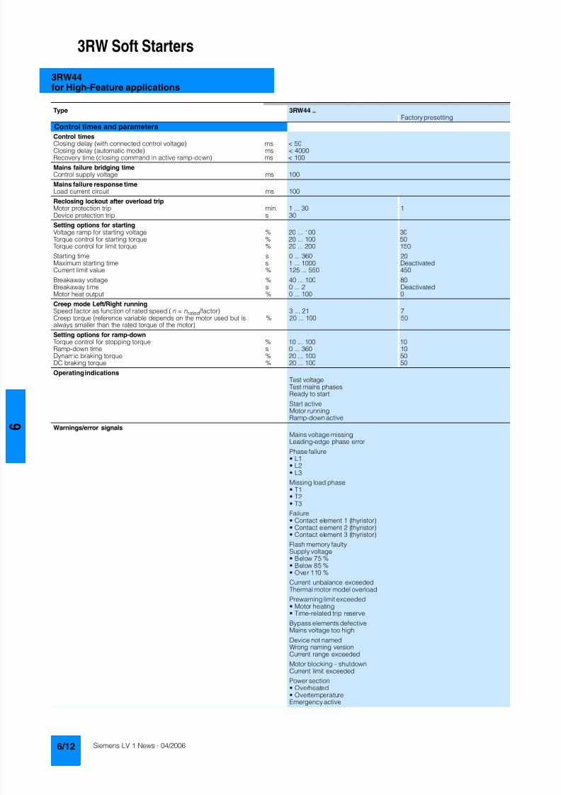
8122019 Arr Estado Solido
httpslidepdfcomreaderfullarr-estado-solido 1640
3RW Soft Starters
3RW44for High-Feature applications
Type 3RW44 Factory presetting
Control times and parameters
Control timesClosing delay (with connected control voltage) ms lt 50Closing delay (automatic mode) ms lt 4000Recovery time (closing command in active ramp-down) ms lt 100
Mains failure bridging timeControl supply voltage ms 100
Mains failure response timeLoad current circuit ms 100
Reclosing lockout after overload tripMotor protection trip min 1 30 1Device protection trip s 30
Setting options for startingVoltage ramp for starting voltage 20 100 30Torque control for starting torque 20 100 50Torque control for limit torque 20 200 150
Starting time s 0 360 20Maximum starting time s 1 1000 DeactivatedCurrent limit value 125 550 450
Breakaway voltage 40 100 80Breakaway time s 0 2 DeactivatedMotor heat output 0 100 0
Creep mode LeftRight runningSpeed factor as function of rated speed (n = n rated factor) 3 21 7Creep torque (reference variable depends on the motor used but isalways smaller than the rated torque of the motor)
20 100 50
Setting options for ramp-downTorque control for stopping torque 10 100 10Ramp-down time s 0 360 10Dynamic braking torque 20 100 50DC braking torque 20 100 50
Operating indicationsTest voltageTest mains phasesReady to start
Start active
Motor runningRamp-down active
Warningserror signalsMains voltage missingLeading-edge phase error
Phase failurebull L1bull L2bull L3
Missing load phasebull T1bull T2bull T3
Failurebull Contact element 1 (thyristor)bull Contact element 2 (thyristor)bull Contact element 3 (thyristor)
Flash memory faulty
Supply voltagebull Below 75 bull Below 85 bull Over 110
Current unbalance exceededThermal motor model overload
Prewarning limit exceededbull Motor heatingbull Time-related trip reserve
Bypass elements defectiveMains voltage too high
Device not namedWrong naming versionCurrent range exceeded
Motor blocking ndash shutdownCurrent limit exceeded
Power section
bull Overheatedbull OvertemperatureEmergency active
8122019 Arr Estado Solido
httpslidepdfcomreaderfullarr-estado-solido 1740
3RW Soft Starters
3RW44for High-Feature applications
1) Parameter motor left possible only in conjunction with creep mode
Type 3RW44 Factory presetting
Control times and parameters
Warningserror signals (contd)Temperature sensorbull Overloadbull Open-circuitbull Short-circuit
Ground faultbull Detectedbull Shutdown
Connection abort in manual modeMax number of starts exceeded I e limit value overshootundershoot
Cooling timebull Motor activebull Switch block active
Heat sink sensorbull Open-circuitbull Short-circuit
Quick-stop functionSwitch block faulty I e class setting not permissible
Control inputsInput 1 Motor right parameter set 1Input 2 No actionInput 3 No actionInput 4 Trip reset
Parameterizing options for control inputs 1 4 No actionLocal manual modeEmergency startCreep speedQuick-stopTrip reset
Motor right parameter set 1Motor left parameter set 11) Motor right parameter set 2Motor left parameter set 21) Motor right parameter set 3Motor left parameter set 31)
Relay outputsOutput 1 ON periodOutput 2 No actionOutput 3 No actionOutput 4 Group fault
Parameterizing options for relay outputs 1 3 No actionPAA output 1PAA output 2
Input 1Input 2Input 3Input 4
Ramp-upOperationBypassRamp-downON periodCommand motor on
FanDC braking contactor
Group warningGroup faultBus faultDevice error
Power onReady to start
Motor temperature sensors Deactivated DeactivatedThermoclickPTC type A
8122019 Arr Estado Solido
httpslidepdfcomreaderfullarr-estado-solido 1840
3RW Soft Starters
3RW44for High-Feature applications
1) Current limit on soft starter set to 350 I M
2) For intermittent duty S4 with ON period = 70 T u = 40 degC stand-aloneinstallation vertical The quoted operating frequencies do not apply forautomatic mode
3) Maximum adjustable rated motor current I M dependent on CLASS setting
Type 3RW44 -BC4 3RW44 -BC5 3RW44 -BC6
Power electronics
Rated operational voltage for inline circuit V 200 460 AC 400 600 AC 400 690 AC
Tolerance -15+10 -15+10 -15+10Rated operational voltage for inside-delta circuit V 200 460 AC 400 600 AC 400 600 ACTolerance -15+10 -15+10 -15+10
Rated frequency Hz 50 60Tolerance plusmn10
Continuous operation at 40 degC ( of I e) 115
Minimum load ( of set motor current I M) 8
Maximum conductor length between soft starter and motor m 200
Permissible installation height m 5000 (derating from 1000 see characteristics) higher on request
Permissible mounting position
Permissible ambient temperatureOperation degC 0 +60 (derating from +40)Storage degC -25 +80
Degree of protection IP00
Type 3RW44 22 3RW44 23 3RW44 24 3RW44 25 3RW44 26 3RW44 27
Power electronics
Rated operational current I e 29 36 47 57 77 93
Load rating with rated operational current I ebull Acc to IEC and ULCSA for individual mounting
at 405060 degC AC-53a A 292623 363229 474237 575145 776859 938272
Smallest adjustable rated motor current I Mfor the motor overload protection
A 5 7 9 11 15 18
Power lossbull In operation after completed ramp-up with uninterrupted rated
operational current (40 degC) approx W 8 10 32 36 45 55bull During starting with current limit set to 350 I M (40 degC) W 400 470 600 725 940 1160
Permissible rated motor current and starts per hour
bull Normal starting (Class 5)- Rated motor current I M
1) starting time 5 s A 29 36 47 57 77 93- Starts per hour2) 1h 41 34 41 41 41 41
- Rated motor current I M1)3) starting time 10 s A 29 36 47 57 77 93
- Starts per hour2) 1h 20 15 20 20 20 20
bull Normal starting (Class 10)- Rated motor current I M
1) starting time 10 s A 29 36 47 57 77 93- Starts per hour2) 1h 20 15 20 20 20 20
- Rated motor current I M1)3) starting time 20 s A 29 36 47 57 77 93
- Starts per hour2) 1h 10 6 10 10 8 8
bull Normal starting (Class 15)- Rated motor current I M
1) starting time 15 s A 29 36 47 57 77 93- Starts per hour2) 1h 13 9 13 13 13 13
- Rated motor current I M1)3) starting time 30 s A 29 36 47 57 77 93
- Starts per hour2) 1h 6 4 6 6 6 6
bull For heavy starting (Class 20)- Rated motor current I M
1) starting time 20 s A 29 36 47 57 73 88- Starts per hour2) 1h 10 6 10 10 10 10
- Rated motor current I M1)3) starting time 40 s A 29 36 47 57 73 88
- Starts per hour2) 1h 4 2 4 5 18 08
bull For very heavy starting (Class 30)- Rated motor current I M
1) starting time 30 s A 29 36 44 57 65 77- Starts per hour2) 1h 6 4 6 6 6 6
- Rated motor current I M1)3) starting time 60 s A 29 36 44 57 65 77
- Starts per hour2) 1h 18 08 33 15 2 1
8122019 Arr Estado Solido
httpslidepdfcomreaderfullarr-estado-solido 1940
3RW Soft Starters
3RW44for High-Feature applications
1) Current limit on soft starter set to 350 I M
2) For intermittent duty S4 with ON period = 70 T u = 40 degC stand-aloneinstallation vertical The quoted operating frequencies do not apply forautomatic mode
3) Maximum adjustable rated motor current I M dependent on CLASS setting
Type 3RW44 34 3RW44 35 3RW44 36
Power electronics
Rated operational current I e 113 134 162
Load rating with rated operational current I ebull Acc to IEC and ULCSA for individual mounting AC-53a
- at 40 degC A 113 134 162- at 50 degC A 100 117 145- at 60 degC A 88 100 125
Smallest adjustable rated motor current I Mfor the motor overload protection
A 22 26 32
Power lossbull In operation after completed ramp-up with uninterrupted rated
operational current (40 degC) approx W 64 76 95bull During starting with current limit set to 350 I M (40 degC) W 1350 1700 2460
Permissible rated motor current and starts per hour
bull Normal starting (Class 5)- Rated motor current I M
1) starting time 5 s A 113 134 162- Starts per hour2) 1h 41 39 41
- Rated motor current I M1)3) starting time 10 s A 113 134 162
- Starts per hour2) 1h 20 15 20
bull Normal starting (Class 10)- Rated motor current I M
1) starting time 10 s A 113 134 162- Starts per hour2) 1h 20 15 20
- Rated motor current I M1)3) starting time 20 s A 113 134 162
- Starts per hour2) 1h 9 6 7
bull Normal starting (Class 15)- Rated motor current I M
1) starting time 15 s A 113 134 162- Starts per hour2) 1h 13 9 12
- Rated motor current I M1)3) starting time 30 s A 113 134 162
- Starts per hour2) 1h 6 6 1
bull For heavy starting (Class 20)- Rated motor current I M
1) starting time 20 s A 106 125 147- Starts per hour2) 1h 9 9 10
- Rated motor current I M1)3) starting time 40 s A 106 125 147
- Starts per hour2) 1h 15 2 1
bull For very heavy starting (Class 30)- Rated motor current I M
1) starting time 30 s A 91 110 120
- Starts per hour2) 1h 6 6 6- Rated motor current I M
1)3) starting time 60 s A 91 110 120- Starts per hour2) 1h 2 2 2
8122019 Arr Estado Solido
httpslidepdfcomreaderfullarr-estado-solido 2040
3RW Soft Starters
3RW44for High-Feature applications
1) Current limit on soft starter set to 350 I M
2) For intermittent duty S4 with ON period = 70 T u = 40 degC stand-aloneinstallation vertical The quoted operating frequencies do not apply forautomatic mode
3) Maximum adjustable rated motor current I M dependent on CLASS setting
Type 3RW44 43 3RW44 44 3RW44 45 3RW44 46 3RW44 47
Power electronics
Rated operational current I e 203 250 313 356 432
Load rating with rated operational current I ebull Acc to IEC and ULCSA for individual mounting AC-53a
- at 40 degC A 203 250 313 356 432- at 50 degC A 180 215 280 315 385- at 60 degC A 156 185 250 280 335
Smallest adjustable rated motor current I Mfor the motor overload protection
A 40 50 62 71 86
Power lossbull In operation after completed ramp-up with uninterrupted rated
operational current (40 degC) approx W 89 110 145 174 232bull During starting with current limit set to 350 I M (40 degC) W 3350 4000 4470 5350 5860
Permissible rated motor current and starts per hour
bull Normal starting (Class 5)- Rated motor current I M
1) starting time 5 s A 203 250 313 356 432- Starts per hour2) 1h 41 41 41 41 39
- Rated motor current I M1)3) starting time 10 s A 203 250 313 356 432
- Starts per hour2) 1h 20 20 19 17 16
bull Normal starting (Class 10)- Rated motor current I M
1) starting time 10 s A 203 250 313 356 432- Starts per hour2) 1h 20 20 19 17 16
- Rated motor current I M1)3) starting time 20 s A 203 250 313 356 432
- Starts per hour2) 1h 9 10 6 4 5
bull Normal starting (Class 15)- Rated motor current I M
1) starting time 15 s A 203 240 313 325 402- Starts per hour2) 1h 13 13 10 13 11
- Rated motor current I M1)3) starting time 30 s A 203 240 313 325 402
- Starts per hour2) 1h 3 6 1 2 1
bull For heavy starting (Class 20)- Rated motor current I M
1) starting time 20 s A 195 215 275 285 356- Starts per hour2) 1h 10 10 10 10 10
- Rated motor current I M1)3) starting time 40 s A 195 215 275 285 356
- Starts per hour2) 1h 1 5 1 3 1
bull For very heavy starting (Class 30)- Rated motor current I M
1) starting time 30 s A 162 180 220 240 285
- Starts per hour2) 1h 6 6 6 6 6- Rated motor current I M
1)3) starting time 60 s A 162 180 220 240 285- Starts per hour2) 1h 3 3 3 2 1
8122019 Arr Estado Solido
httpslidepdfcomreaderfullarr-estado-solido 2140
3RW Soft Starters
3RW44for High-Feature applications
1) Current limit on soft starter set to 350 I M
2) For intermittent duty S4 with ON period = 70 T u = 40 degC stand-aloneinstallation vertical The quoted operating frequencies do not apply forautomatic mode
3) Maximum adjustable rated motor current I M dependent on CLASS setting
Type 3RW44 53 3RW44 54 3RW44 55 3RW44 56 3RW44 57 3RW44 58
Power electronics
Rated operational current I e 551 615 693 780 880 970
Load rating with rated operational current I ebull Acc to IEC and ULCSA for individual mounting AC-53a
- at 40 degC A 551 615 693 780 880 970- at 50 degC A 494 551 615 693 780 850- at 60 degC A 438 489 551 615 693 760
Smallest adjustable rated motor current I Mfor the motor overload protection
A 110 123 138 156 176 194
Power lossbull In operation after completed ramp-up with uninterrupted rated
operational current (40 degC) approx W 159 186 220 214 250 270bull During starting with current limit set to 350 I M (40 degC) W 7020 8100 9500 11100 13100 15000
Permissible rated motor current and starts per hour
bull Normal starting (Class 5)- Rated motor current I M
1) starting time 5 s A 551 615 693 780 880 970- Starts per hour2) 1h 41 41 37 33 22 17
- Rated motor current I M1)3) starting time 10 s A 551 615 693 780 880 970
- Starts per hour2) 1h 20 20 16 13 8 5
bull Normal starting (Class 10)- Rated motor current I M
1) starting time 10 s A 551 615 693 780 880 970- Starts per hour2) 1h 20 20 16 13 8 5
- Rated motor current I M1)3) starting time 20 s A 551 615 693 780 880 970
- Starts per hour2) 1h 10 9 6 4 03 03
bull Normal starting (Class 15)- Rated motor current I M
1) starting time 15 s A 551 615 666 723 780 821- Starts per hour2) 1h 13 13 11 9 8 8
- Rated motor current I M1)3) starting time 30 s A 551 615 666 723 780 821
- Starts per hour2) 1h 6 4 3 1 04 05
bull For heavy starting (Class 20)- Rated motor current I M
1) starting time 20 s A 551 591 633 670 710 740- Starts per hour2) 1h 10 10 7 8 8 9
- Rated motor current I M1)3) starting time 40 s A 551 591 633 670 710 740
- Starts per hour2) 1h 4 2 1 1 04 1
bull For very heavy starting (Class 30)- Rated motor current I M
1) starting time 30 s A 500 525 551 575 600 630
- Starts per hour2) 1h 6 6 6 6 6 6- Rated motor current I M
1)3) starting time 60 s A 500 525 551 575 600 630- Starts per hour2) 1h 2 1 1 1 15 1
8122019 Arr Estado Solido
httpslidepdfcomreaderfullarr-estado-solido 2240
3RW Soft Starters
3RW44for High-Feature applications
1) When connecting cable lugs to DIN 46235 use 3RT19 56-4EA1 terminalcover for conductor cross-sections from 95 mmsup2 to ensure phase spacing
2) When connecting cable lugs to DIN 46234 the 3RT19 66-4EA1 terminalcover must be used for conductor cross-sections of 240 mmsup2 and more aswell as DIN 46235 for conductor cross-sections of 185 mmsup2 and more tokeep the phase clearance
Type 3RW44 2 3RW44 3 3RW44 4 3RW44 5
Conductor cross-sections
Screw
terminals
Main conductors
with box terminal 3RT19 55-4G (55 kW) 3RT19 66-4G
Front clampingpoint connected
bull Finely stranded with end sleeve mm2 16 70 70 240bull Finely stranded without end sleeve mm2 16 70 70 240bull Stranded mm2 16 70 95 300
bull Ribbon cable conductors(number x width x thickness)
mm min 3 x 9 x 08max 6 x 155 x 08
min 6 x 9 x 08max 20 x 24 x 05
bull AWG conductors solid or stranded AWG 6 20 30 600 kcmil
Rear clamping pointconnected
bull Finely stranded with end sleeve mm2 16 70 120 185bull Finely stranded without end sleeve mm2 16 70 120 185bull Stranded mm2 16 70 120 240
bull Ribbon cable conductors(number x width x thickness)
mm min 3 x 9 x 08max 6 x 155 x 08
min 6 x 9 x 08max 20 x 24 x 05
bull AWG conductors solid or stranded AWG 6 20 250 500 kcmil
Both clamping
points connected
bull Finely stranded with end sleeve mm2 max 1 x 50 1 x 70 min 2 x 50 max 2 x 185
bull Finely stranded without end sleeve mm2 max 1 x 50 1 x 70 min 2 x 50 max 2 x 185bull Stranded mm2 max 2 x 70 max 2 x 70 max 2 x 240
bull Ribbon cable conductors(number x width x thickness)
mm max 2 x (6 x 155 x 08) max 2 x (20 x 24 x 05)
bull AWG conductors solid or stranded AWG max 2 x 10 min 2 x 20max 2 x 500 kcmil
bull Terminal screws M10 (hexagon socket AF4) M12 (hexagon socket AF5)- Pickup torque 10 12 20 22
90 110 180 195
Screwterminals
Main conductors
with box terminal 3RT19 56-4G
Front or rear clamp-ing point connected
bull Finely stranded with end sleeve mm2 16 120bull Finely stranded without end sleeve mm2 16 120bull Stranded mm2 16 120
bull Ribbon cable conductors(number x width x thickness)
mm min 3 x 9 x 08max 6 x 155 x 08
bull AWG conductors solid or stranded AWG 6 250 kcmil
Both clampingpoints connected
bull Finely stranded with end sleeve mm2 max 1 x 95 1 x 120bull Finely stranded without end sleeve mm2 max 1 x 95 1 x 120bull Stranded mm2 max 2 x 120
bull Ribbon cable conductors(number x width x thickness)
mm max 2 x (10 x 155 x 08)
bull AWG conductors solid or stranded AWG max 2 x 30
Screwterminals
Main conductors
Without box terminalrail connection
bull Finely stranded with cable lug mm2 16 951) 50 2402) 50 2402)
bull Stranded with cable lug mm2 25 1201) 70 2402) 70 2402)
bull AWG conductors solid or stranded AWG 4 250 kcmil 20 500 kcmil 10 500 kcmil
bull Connecting bar (max width) mm 17 25 60
bull Terminal screws M8 x 25 (AF13) M10 x 30 (AF17) M12 x 40- Pickup torque NM 10 14 14 24 20 35lbin 89 124 124 210 177 310
8122019 Arr Estado Solido
httpslidepdfcomreaderfullarr-estado-solido 2340
3RW Soft Starters
3RW44for High-Feature applications
Soft starters Type 3RW44
Conductor cross-sections
Auxiliary conductors (1 or 2 conductors can be connected)
Screw terminals
bull Solid mm2 2 x 05 25bull Finely stranded with end sleeve mm2 2 x 05 15
bull AWG cables- Solid or stranded AWG 2 x 20 14- Finely stranded with end sleeve AWG 2 x 20 16
bull Terminal screws- Pickup torque NM 07 09
lbin 7 8
Spring-loaded terminals
bull Solid mm2 2 x 025 25bull Finely stranded with end sleeve mm2 2 x 025 15bull AWG conductors solid or stranded AWG 2 x 24 14
Standard Parameters
Electromagnetic compatibility acc to EN 60947-4-2
EMC interference immunityElectrostatic discharge (ESD) EN 61000-4-2 plusmn4 kV contact discharge plusmn8 kV air discharge
Electromagnetic RF fields EN 61000-4-3 Frequency range 80 1000 MHz with 80 at 1 kHzDegree of severity 3 10 Vm
Conducted RF interference EN 61000-4-6 Frequency range 150 kHz 80 MHz with 80 at 1 kHzInterference 10 V
RF voltages and RF currents on conductorsBurst EN 61000-4-4 plusmn2 kV5 kHzSurge EN 61000-4-5 plusmn1 kV line to line
plusmn2 kV line to ground
EMC interference emission
EMC interference field strength EN55011 Limit value of Class A at 30 1000 MHz
Radio interference voltage EN55011 Limit value of Class A at 015 30 MHz
Is an RI suppression filter necessary
Degree of noise suppression A (industrial applications) no
8122019 Arr Estado Solido
httpslidepdfcomreaderfullarr-estado-solido 2440
3RW Soft Starters
3RW44for High-Feature applications
Fuse assignment
The coordination type to which the motor feeder with soft starteris mounted depends on the application-specific requirements
Normally fuseless mounting (combination of motor starter pro-tector and soft starter) is sufficient If type 2 coordination is to befulfilled semiconductor fuses must be fitted in the motor feeder
1) The rated motor current must be considered when selecting the devices
2) The types of coordination are explained in more detail in theTechnical information LV 1 T under ndash Fuseless Load Feeders
Inline circuit fuseless version
Soft starters Motor starter protectorscircuit-breakers1)
Rated current 440 V +10 Rated currentG1 Q1Type A Type A
Type of coordination 12) 3RW44 22 3RW44 27 I q = 32 kA 3RW44 34 and 3RW44 35 I q = 16 kA 3RW44 36 3RW44 57 I q = 65 kA
3RW44 22 29 3RV10 42-4HA10 503RW44 23 36 3RV10 42-4JA10 633RW44 24 47 3RV10 42-4KA10 75
3RW44 25 57 3RV10 42-4LA10 903RW44 26 77 3RV10 42-4MA10 1003RW44 27 93 3RV10 42-4MA10 100
3RW44 34 113 3VL17 16-2DD36 1603RW44 35 134 3VL17 16-2DD36 1603RW44 36 162 3VL37 25-2DC36 250
3RW44 43 203 3VL47 31-3DC36 3153RW44 44 250 3VL47 31-3DC36 3153RW44 45 313 3VL47 40-3DC36 400
3RW44 46 356 3VL47 40-3DC36 4003RW44 47 432 3VL57 50-3DC36 500
3RW44 53 551 3VL67 80-3DE36 8003RW44 54 615 3VL67 80-3DE36 8003RW44 55 693 3VL67 80-3DE36 800
3RW44 56 780 3VL77 10-3AB36 10003RW44 57 880 3VL77 10-3AB36 10003RW44 58 970 3VL77 12-3AB36 1200
8122019 Arr Estado Solido
httpslidepdfcomreaderfullarr-estado-solido 2540
3RW Soft Starters
3RW44for High-Feature applications
1) If the ramp-down function Combined braking is selected no brakingcontactor is requiredIf the ramp-down function DC braking is selected a braking contactormust also be used (see table for type)For applications with large centrifugal masses (J Load gt J Motor) werecommend the function DC braking
2) Additional auxiliary relay K4LZXRT4A4T30(3RW44 soft starter with rated control supply voltage 230 V AC)LZXRT4A4S15(3RW44 soft starter with rated control supply voltage 115 V AC)
3) The types of coordination are explained in more detail in theTechnical information LV 1 T under ndash Fuseless Load Feeders
Inline circuit fused version (line protection only)
Soft starters Line protections Line contactorsup to 400 V
Braking contactors1)2)
Rated current 690 V +5 Rated current Size (optional) (for typical circuit see page 633)G1 F1 K1 K2 K3Type A Type A Type Type Type
Type of coordination 13) I q = 65 kA
3RW44 22 29 3NA3 820-6 50 00 3RT10 34 3RT15 26 --3RW44 23 36 3NA3 822-6 63 00 3RT10 35 3RT15 26 --
3RW44 24 47 3NA3 824-6 80 00 3RT10 36 3RT15 35 --3RW44 25 57 3NA3 830-6 100 00 3RT10 44 3RT15 35 --3RW44 26 77 3NA3 132-6 125 1 3RT10 45 3RT10 24 3RT10 353RW44 27 93 3NA3 136-6 160 1 3RT10 46 3RT10 25 3RT10 36
3RW44 34 113 3NA3 244-6 250 2 3RT10 54 3RT10 34 3RT10 443RW44 35 134 3NA3 244-6 250 2 3RT10 55 3RT10 36 3RT10 453RW44 36 162 3NA3 365-6 500 3 3RT10 56 3RT10 44 3RT10 45
3RW44 43 203 2 x 3NA3 354-6 2 x 355 3 3RT10 64 3RT10 44 3RT10 543RW44 44 250 2 x 3NA3 354-6 2 x 355 3 3RT10 65 3RT10 44 3RT10 553RW44 45 313 2 x 3NA3 365-6 2 x 500 3 3RT10 75 3RT10 54 3RT10 56
3RW44 46 356 2 x 3NA3 365-6 2 x 500 3 3RT10 75 3RT10 54 3RT10 563RW44 47 432 2 x 3NA3 365-6 2 x 500 3 3RT10 76 3RT10 55 3RT10 64
3RW44 53 551 2 x 3NA3 365-6 2 x 500 3 3TF68 44-0CM7 3TF68 44-0CM7 3TF68 44-0CM73RW44 54 615 2 x 3NA3 365-6 2 x 500 3 3TF68 44-0CM7 3TF68 44-0CM7 3TF68 44-0CM73RW44 55 693 2 x 3NA3 365-6 2 x 500 3 3TF69 44-0CM7 3TF69 44-0CM7 3TF69 44-0CM7
3RW44 56 780 2 x 3NA3 365-6 2 x 500 3 3TF69 44-0CM7 3TF69 44-0CM7 3TF69 44-0CM73RW44 57 880 2 x 3NA3 365-6 2 x 500 3 2 x 3TF69 44-0CM7 2 x 3TF69 44-0CM7 2 x 3TF69 44-0CM7
3RW44 58 970 3 x 3NA3 365-6 3 x 500 3
8122019 Arr Estado Solido
httpslidepdfcomreaderfullarr-estado-solido 2640
3RW Soft Starters
3RW44for High-Feature applications
1) If the ramp-down function Combined braking is selected no brakingcontactor is requiredIf the ramp-down function DC braking is selected a braking contactormust also be used (see table for type)For applications with large centrifugal masses (J Load gt J Motor) werecommend the function DC braking
2) Additional auxiliary relay K4LZXRT4A4T30(3RW44 soft starter with rated control supply voltage 230 V AC)LZXRT4A4S15(3RW44 soft starter with rated control supply voltage 115 V AC)
3) The types of coordination are explained in more detail in theTechnical information LV 1 T under ndash Fuseless Load Feeders
Inline circuit fused version with 3NE1 SITOR all-range fuse (semiconductor and line protection)
Soft starters All-range fuses Line contactors upto 400 V
Braking contactors1)2)
Ratedcurrent
Rated current Voltage Size (optional) (for typical circuit see page 633)
G1 Frsquo1 K1 K2 K3Type A Type A V Type Type Type
Type of coordination 23) I q = 65 kA
3RW44 22 29 3NE1 020-2 80 690 +5 00 3RT10 34 3RT15 26 --
3RW44 23 36 3NE1 020-2 80 690 +5 00 3RT10 35 3RT15 26 --3RW44 24 47 3NE1 021-2 100 690 +5 00 3RT10 36 3RT15 35 --
3RW44 25 57 3NE1 022-2 125 690 +5 00 3RT10 44 3RT15 35 --3RW44 26 77 3NE1 022-2 125 690 +5 00 3RT10 45 3RT10 24 3RT10 353RW44 27 93 3NE1 024-2 160 690 +5 1 3RT10 46 3RT10 25 3RT10 36
3RW44 34 113 3NE1 225-2 200 690 +5 1 3RT10 54 3RT10 34 3RT10 443RW44 35 134 3NE1 227-2 250 690 +5 1 3RT10 55 3RT10 36 3RT10 453RW44 36 162 3NE1 227-2 250 690 +5 1 3RT10 56 3RT10 44 3RT10 45
3RW44 43 203 3NE1 230-2 315 600 +10 1 3RT10 64 3RT10 44 3RT10 543RW44 44 250 3NE1 331-2 350 460 +10 2 3RT10 65 3RT10 44 3RT10 553RW44 45 313 3NE1 333-2 450 690 +5 2 3RT10 75 3RT10 54 3RT10 56
3RW44 46 356 3NE1 334-2 500 690 +5 2 3RT10 75 3RT10 54 3RT10 563RW44 47 432 3NE1 435-2 560 690 +5 3 3RT10 76 3RT10 55 3RT10 64
3RW44 53 551 2 x 3NE1 334-2 500 690 +10 2 3TF68 44-0CM7 3TF68 44-0CM7 3TF68 44-0CM73RW44 54 615 2 x 3NE1 334-2 500 690 +10 2 3TF68 44-0CM7 3TF68 44-0CM7 3TF68 44-0CM73RW44 55 693 2 x 3NE1 334-2 500 690 +10 2 3TF69 44-0CM7 3TF69 44-0CM7 3TF69 44-0CM7
3RW44 56 780 2 x 3NE1 435-2 560 690 +10 3 3TF69 44-0CM7 3TF69 44-0CM7 3TF69 44-0CM7
3RW44 57 880 2 x 3NE1 435-2 560 690 +10 3 2 x 3TF69 44-0CM7 2 x 3TF69 44-0CM7 2 x 3TF69 44-0CM73RW44 58 970 2 x 3NE1 435-2 560 690 +10 3
8122019 Arr Estado Solido
httpslidepdfcomreaderfullarr-estado-solido 2740
3RW Soft Starters
3RW44for High-Feature applications
1) If the ramp-down function Combined braking is selected no brakingcontactor is requiredIf the ramp-down function DC braking is selected a braking contactor
must also be used (see table for type)For applications with large centrifugal masses (J Load gt J Motor) werecommend the function DC braking
2) Additional auxiliary relay K4LZXRT4A4T30(3RW44 soft starter with rated control supply voltage 230 V AC)
LZXRT4A4S15(3RW44 soft starter with rated control supply voltage 115 V AC)
3) The types of coordination are explained in more detail in theTechnical information LV 1 T under ndash Fuseless Load Feeders
Inline circuit fused version with 3NE or 3NC SITOR semiconductor fuse(semiconductor protection by fuse lead and overload protection by circuit-breaker)
Soft starters Semiconductor fuses minimum Semiconductor fuses maximum Semiconductor fuses (cylinder)
Ratedcurrent
Rated current Size Rated current Size Rated current Size
G1 F3 F3 F3Type A Type A Type A Type A
Type of coordination 23) I q = 65 kA
3RW44 22 29 3NE4 120 80 0 3NE4 121 100 0 3NC2 280 80 22 x 58
3RW44 23 36 3NE4 121 100 0 3NE4 122 125 0 3NC2 200 100 22 x 583RW44 24 47 3NE4 121 100 0 3NE4 122 125 0 3NC2 200 100 22 x 58
3RW44 25 57 3NE4 122 125 0 3NE4 124 160 03RW44 26 77 3NE4 124 160 0 3NE4 124 160 03RW44 27 93 3NE3 224 160 1 3NE3 333 450 2
3RW44 34 113 3NE3 225 200 1 3NE3 335 560 23RW44 35 134 3NE3 225 200 1 3NE3 335 560 23RW44 36 162 3NE3 227 250 1 3NE3 333 450 2
3RW44 43 203 3NE3 230-0B 315 1 3NE3 333 450 23RW44 44 250 3NE3 230-0B 315 1 3NE3 333 450 23RW44 45 313 3NE3 233 450 1 3NE3 336 630 2
3RW44 46 356 3NE3 333 450 2 3NE3 336 630 23RW44 47 432 3NE3 335 560 2 3NE3 338-8 800 2
3RW44 53 551 2 x 3NE3 335 560 2 3 x 3NE3 334-0B 500 23RW44 54 615 2 x 3NE3 335 560 2 3 x 3NE3 334-0B 500 23RW44 55 693 2 x 3NE3 335 560 2 3 x 3NE3 334-0B 500 2
3RW44 56 780 2 x 3NE3 336 630 2 2 x 3NE3 340-8 900 2
3RW44 57 880 2 x 3NE3 336 630 2 2 x 3NE3 340-8 900 23RW44 58 970 2 x 3NE3 336 630 2 2 x 3NE3 340-8 900 2
Soft starters Line contactorsup to 400 V
Braking contactors1)2) Motor starter protectors circuit-breakers
Max line protection
Ratedcurrent
(optional) (for typical circuit see page 633) 440 V +10 Rated current 690 V +5 Rated current Size
G1 K1 Q1 F1Type A Type Type Type Type A Type A
Type of coordination 23) 3RW44 22 3RW44 27 I q = 32 kA 3RW44 34 and 3RW44 35 I q = 16 kA 3RW44 36 3RW44 57 I q = 65 kA
3RW44 22 29 3RT10 34 3RT15 26 -- 3RV10 41-4HA10 50 3NA3 820-6 50 003RW44 23 36 3RT10 35 3RT15 26 -- 3RV10 41-4JA10 63 3NA3 822-6 63 003RW44 24 47 3RT10 36 3RT15 35 -- 3RV10 41-4KA10 75 3NA3 824-6 80 00
3RW44 25 57 3RT10 44 3RT15 35 -- 3RV10 41-4LA10 90 3NA3 830-6 100 003RW44 26 77 3RT10 45 3RT10 24 3RT10 35 3RV10 41-4MA10 100 3NA3 132-6 125 13RW44 27 93 3RT10 46 3RT10 25 3RT10 36 3RV10 41-4MA10 100 3NA3 136-6 160 1
3RW44 34 113 3RT10 54 3RT10 34 3RT10 44 3VL17 16-1DD36 160 3NA3 244-6 250 2
3RW44 35 134 3RT10 55 3RT10 36 3RT10 45 3VL17 16-1DD36 160 3NA3 244-6 250 23RW44 36 162 3RT10 56 3RT10 44 3RT10 45 3VL37 25-1DC36 250 3NA3 365-6 500 3
3RW44 43 203 3RT10 64 3RT10 44 3RT10 54 3VL47 31-1DC36 315 2 x 3NA3 354-6 2 x 355 33RW44 44 250 3RT10 65 3RT10 44 3RT10 55 3VL47 31-1DC36 315 2 x 3NA3 354-6 2 x 355 33RW44 45 313 3RT10 75 3RT10 54 3RT10 56 3VL47 40-1DC36 400 2 x 3NA3 365-6 2 x 500 3
3RW44 46 356 3RT10 75 3RT10 54 3RT10 56 3VL47 40-1DC36 400 2 x 3NA3 365-6 2 x 500 33RW44 47 432 3RT10 76 3RT10 55 3RT10 64 3VL57 50-1DC36 500 2 x 3NA3 365-6 2 x 500 3
3RW44 53 551 3TF68 44-0CM7 3TF68 44-0CM7 3TF68 44-0CM7 3VL67 80-1AB36 800 2 x 3NA3 365-6 2 x 500 33RW44 54 615 3TF68 44-0CM7 3TF68 44-0CM7 3TF68 44-0CM7 3VL67 80-1AB36 800 2 x 3NA3 365-6 2 x 500 33RW44 55 693 3TF69 44-0CM7 3TF69 44-0CM7 3TF69 44-0CM7 3VL67 80-1AB36 800 2 x 3NA3 365-6 2 x 500 3
3RW44 56 780 3TF69 44-0CM7 3TF69 44-0CM7 3TF69 44-0CM7 3VL77 10-1AB36 1000 2 x 3NA3 365-6 2 x 500 33RW44 57 880 2 x
3TF69 44-0CM72 x3TF69 44-0CM7
2 x3TF69 44-0CM7
3VL77 10-1AB36 1000 2 x 3NA3 365-6 2 x 500 3
3RW44 58 970 3VL77 12-1AB36 1200 3 x 3NA3 365-6 3 x 500 3
8122019 Arr Estado Solido
httpslidepdfcomreaderfullarr-estado-solido 2840
3RW Soft Starters
3RW44for High-Feature applications
1) The types of coordination are explained in more detail in theTechnical information LV 1 T under ndash Fuseless Load FeedersThe type of coordination 2 only refers to soft starters not to feeder compo-nents ( I q = 65 kA)
Inside-delta circuit fused version with 3NE or 3NC SITOR fuses(semiconductor protection by fuse lead and overload protection by circuit-breaker)
Soft starters Semiconductor fuses minimum Semiconductor fuses maximum Semiconductor fuses (cylinder)
Ratedcurrent
Rated current Size Rated current Size Rated current Size
G1 F3 F3 F3Type A Type A Type A Type A
Type of coordination 21)
3RW44 22 50 3NE4 120 80 0 3NE4 121 100 0 3NC2 280 80 22 x 58
3RW44 23 62 3NE4 121 100 0 3NE4 122 125 0 3NC2 200 100 22 x 583RW44 24 81 3NE4 121 100 0 3NE4 122 125 0 3NC2 200 100 22 x 58
3RW44 25 99 3NE4 122 125 0 3NE4 124 160 03RW44 26 133 3NE4 124 160 0 3NE4 124 160 03RW44 27 161 3NE3 224 160 1 3NE3 333 450 2
3RW44 34 196 3NE3 225 200 1 3NE3 335 560 23RW44 35 232 3NE3 225 200 1 3NE3 335 560 23RW44 36 281 3NE3 227 250 1 3NE3 333 450 2
3RW44 43 352 3NE3 230-0B 315 1 3NE3 333 450 23RW44 44 433 3NE3 230-0B 315 1 3NE3 333 450 23RW44 45 542 3NE3 233 450 1 3NE3 336 630 2
3RW44 46 617 3NE3 333 450 2 3NE3 336 630 23RW44 47 748 3NE3 335 560 2 3NE3 338-8 800 2
3RW44 53 954 2 x 3NE3 335 560 2 3 x 3NE3 334-0B 500 23RW44 54 1065 2 x 3NE3 335 560 2 3 x 3NE3 334-0B 500 23RW44 55 1200 2 x 3NE3 335 560 2 3 x 3NE3 334-0B 500 2
3RW44 56 1351 2 x 3NE3 336 630 2 2 x 3NE3 340-8 900 2
3RW44 57 1524 2 x 3NE3 336 630 2 3 x 3NE3 340-8 900 23RW44 58 1680 2 x 3NE3 336 630 2 3 x 3NE3 340-8 900 2
Soft starters Line contactorsup to 400 V
Motor starter protectors cirduit-breakers
Line protections
Ratedcurrent
(optional) 440 V +10 Rated current 690 V +5 Rated current Size
G1 K1 Q1 F1Type A Type Type A Type A
Type of coordination 21)
3RW44 22 50 3RT10 36-1AP04 3RV10 4-4KA10 75 3NA3 824-6 80 003RW44 23 62 3RT10 44-1AP04 3RV10 4-4LA10 90 3NA3 830-6 100 003RW44 24 81 3RT10 46-1AP04 3RV10 4-4MA10 100 3NA3 132-6 125 1
3RW44 25 99 3RT10 54-1AP36 3VL27 16-DC36 160 3NA3 136-6 160 13RW44 26 133 3RT10 55-6AP36 3VL27 16-DC36 160 3NA3 240-6 200 23RW44 27 161 3RT10 56-6AP36 3VL37 20-DC36 200 3NA3 244-6 250 2
3RW44 34 196 3RT10 64-6AP36 3VL37 25-DC36 250 3NA3 360-6 400 3
3RW44 35 232 3RT10 65-6AP36 3VL47 31-DC36 315 3NA3 360-6 400 33RW44 36 281 3RT10 66-6AP36 3VL47 40-DC36 400 2 x 3NA3 360-6 2 x 400 3
3RW44 43 352 3RT10 75-6AP36 3VL47 40-DC36 400 2 x 3NA3 365-6 2 x 500 33RW44 44 433 3RT10 76-6AP36 3VL57 50-DC36 500 2 x 3NA3 365-6 2 x 500 33RW44 45 542 3TF68 44-0CM7 3VL57 63-DC36 800 3 x 3NA3 365-6 3 x 500 3
3RW44 46 617 3TF68 44-0CM7 3VL67 80-AB36 800 3 x 3NA3 365-6 3 x 500 33RW44 47 748 3TF69 3VL67 80-AB36 1000 3 x 3NA3 365-6 3 x 500 3
3RW44 53 954 2 x 3TF68 44-0CM7 3VL77 10-AB36 1000 3 x 3NA3 365-6 3 x 500 33RW44 54 1065 2 x 3TF68 44-0CM7 3VL77 12-AB36 1250 3 x 3NA3 365-6 3 x 500 33RW44 55 1200 2 x 3TF69 44-0CM7 3VL87 16-AB36 1600 3 x 3NA3 365-6 3 x 500 3
3RW44 56 1351 2 x 3TF69 44-0CM7 3VL87 16-AB36 1600 3 x 3NA3 372 3 x 630 33RW44 57 1524 2 x 3TF69 44-0CM7 3VL87 16-AB36 1600 3 x 3NA3 372 3 x 630 33RW44 58 1680 3WL12 20 2000 2 x 3NA3 480 2 x 1000 4
8122019 Arr Estado Solido
httpslidepdfcomreaderfullarr-estado-solido 2940
3RW Soft Starters
3RW44for High-Feature applications
Characteristic curves
Motor protection tripping characteristics for 3RW44(with symmetry)
Admissible mounting height
The admissible operational voltage is reduced to 460 V with a mountingheight of more than 2000 m
Motor protection characteristics for 3RW44(with phase unbalance)
e
2 4 6 101
Class 10 Class 15 Class 20
100
101
102
103
2
4
6
2
4
6
2
4
6
Class 5 Class 30
N S B 0
_ 0 1 5 0 0 a
[ s ]
x
T r i p p i n g t i m e
85
105
70
75
80
90
95
100
N S B 0
_ 0 1 7 0 4
0 1000 2000 3000 4000 5000 O p e r
a t i o n a
l r a
t e d c u r r e n
t I
i n
Mounting height in m
e
e
1001
Class 10 Class 15 Class 20
100
101
102
103
2
4
6
2
4
6
2
4
6
Class 5 Class 30
N S B 0
_ 0 1 7 0 6
[ s ]
x10
T r i p p
i n g
t i m e
8122019 Arr Estado Solido
httpslidepdfcomreaderfullarr-estado-solido 3040
3RW Soft Starters
3RW44for High-Feature applications
More information
Application examples for normal starting (Class 10)
Application examples for heavy starting (Class 20)
Application examples for very heavy starting (Class 30)
NoteThese tables present sample setting values and device sizesThey are intended only for the purposes of information and arenot binding The setting values depend on the application inquestion and must be optimized during commissioningThe soft starter dimensions should be checked where necessarywith the Win-Soft Starter software or with the help ofTechnical Assistance
Normal starting Class 10 (up to 20 s with 350 I n motor)The soft starter rating can be selected to be as high as the rating of the motor used
Application Conveyor belts Roller conveyors Compressors Small ventilators Pumps Hydraulic pumps
Starting parameters
bull Voltage ramp and currentlimiting- Starting voltage 70 60 50 30 30 30- Starting time s 10 10 10 10 10 10- Current limit value Deactivated Deactivated 4 x I M 4 x I M Deactivated Deactivated
bull Torque ramp- Starting torque 60 50 40 20 10 10- End torque 150 150 150 150 150 150- Starting time 10 10 10 10 10 10
bull Breakaway pulse Deactivated (0 ms) Deactivated (0 ms) Deactivated (0 ms) Deactivated (0 ms) Deactivated (0 ms) Deactivated (0 ms)
Ramp-down mode Smoothramp-down
Smoothramp-down
Free ramp-down Free ramp-down Pump ramp-down Free ramp-down
Heavy starting Class 20 (up to 40 s with 350 I n motor)The soft starter has to be selected one rating class higher than the motor used
Application Stirrers Centrifuges Milling machines
Starting parameters
bull Voltage ramp and currentlimiting- Starting voltage 30 30 30- Starting time s 30 30 30- Current limit value 4 x I M 4 x I M 4 x I M
bull Torque ramp- Starting torque 30 30 30- End torque 150 150 150- Starting time 30 30 30
bull Breakaway pulse Deactivated (0 ms) Deactivated (0 ms) Deactivated (0 ms)
Ramp-down mode Free ramp-down Free ramp-down Free ramp-down or DC braking
Very heavy starting Class 30 (up to 60 s with 350 I n motor)The soft starter has to be selected two rating classes higher than the motor used
Application Large ventilators Mills Breakers Circular sawbandsaws
Starting parameters
bull Voltage ramp and currentlimiting- Starting voltage 30 50 50 30- Starting time s 60 60 60 60- Current limit value 4 x I M 4 x I M 4 x I M 4 x I M
bull Torque ramp- Starting torque 20 50 50 20- End torque 150 150 150 150- Starting time 60 60 60 60
bull Breakaway pulse Deactivated (0 ms) 80 300 ms 80 300 ms Deactivated (0 ms)
Ramp-down mode Free ramp-down Free ramp-down Free ramp-down Free ramp-down
8122019 Arr Estado Solido
httpslidepdfcomreaderfullarr-estado-solido 3140
3RW Soft Starters
3RW44for High-Feature applications
Circuit concept
The SIRIUS 3RW44 soft starters can be operated in two differenttypes of circuit
bull Inline circuitThe controls for isolating and protecting the motor are simplyconnected in series with the soft starter The motor isconnected to the soft starter with three leads
bull Inside-delta circuitThe wiring is similar to that of wye-delta starters The phases ofthe soft starter are connected in series with the individual motorwindings The soft starter then only has to carry the phasecurrent amounting to about 58 of the rated motor current(conductor current)
Comparison of the types of circuit
Inline circuitRated current I e corresponds to the rated motor current I n3 leads to the motor
Inside-delta circuit
Rated current I e corresponds to approx 58 of the rated motorcurrent I n6 leads to the motor (as with wye-delta starters)
Which circuit
Using the inline circuit involves the lowest wiring complexityIf the soft starter to motor connections are long this contactsequence is preferableWith the inside-delta circuit there is double the wiring complexitybut a smaller size of device can be used at the same rating
Thanks to choosing the operational mode between the inline cir-cuit and inside-delta circuit the most favorable solution can al-ways be chosen
The braking function is possible only in the inline circuit
Configuration
The 3RW44 solid-state soft starters are designed for normalstarting In case of heavy starting or increased starting
frequency a larger device must be selectedFor long starting times it is recommended to have a PTC ther-mistor detector in the motor This also applies for the ramp-downmodes smooth ramp-down pump ramp-down and DC brakingbecause during the ramp-down time in these modes an addi-tional current loading applies in contrast to free ramp-down
In the motor feeder between the SIRIUS 3RW soft starter and themotor no capacitive elements are permitted (eg no reactive-power compensation equipment) In addition neither staticsystems for reactive-power compensation nor dynamic PFC(Power Factor Correction) must be operated in parallel duringstarting and ramp-down of the soft starter This is important toprevent faults arising on the compensation equipment andor thesoft starter
All elements of the main circuit (such as fuses and controls)
should be dimensioned for direct starting following the localshort-circuit conditions Fuses switching devices and overloadrelays must be ordered separately
The harmonic component load for starting currents must betaken into consideration for the selection of motor starterprotectors (selection of release)
NoteWhen switching on three-phase current motors voltage dropsnormally will occur with all types of starters (direct starters star- delta starters soft starters) On principle the feeding transformermust be configured such that when starting the motor thevoltage drop must occur within the admissible tolerance Whenthe feeding transformer is designed quite scarce the control vol- tage (being independent of the main voltage) should be sup- plied with a separate circuit in order to prevent the soft starterfrom switching off
Serial PC interface PROFIBUS DP communication moduleand parameterizing and operating software Soft Starter ES
The solid-state 3RW44 soft starters have a PC interface forcommunicating with the Soft Starter ES 2006 Smart software orto be connected to an external operating and monitoring mod-ule When using the optional communication module PROFIBUSthe 3RW44 soft starter can be connected to the PROFIBUS netand can communicate via GSD file or software Soft Starter ES2006 Professional
Manual for SIRIUS 3RW44
Besides containing all important information on planning com-missioning and servicing the manual also contains suggestedcircuits and the technical specifications for all devices
Win-Soft Starter selection and simulation program
With this software you can simulate and select all Siemens softstarters taking into account various parameters such as mainsproperties motor and load data and special applicationrequirements
The software is a valuable tool which makes complicatedlengthy manual calculations for determining the required softstarters superfluous
You can order the CD-ROM under the following order numberOrder No E20001-D1020-P302-V2-7400
More information can be found on the Internet athttpwwwsiemenscomsoftstarter
8122019 Arr Estado Solido
httpslidepdfcomreaderfullarr-estado-solido 3240
3RW Soft Starters
3RW44for High-Feature applications
SIRIUS soft starter training course (SD-SIRIUSO)
Siemens offers a 2-day training course on the SIRIUS solid-statesoft starters to keep customers and own personnel up-to-date on
configuring commissioning and servicing issuesPlease direct enquiries and applications to
AampD PT 4 (Trainings-Center Erlangen)Werner-von-Siemens-Str 65D-91052 ErlangenTelefon ++49 9131 729262Telefax ++49 9131 728172sibrainindustrysiemenscomhttp wwwsiemenscomsitrain
8122019 Arr Estado Solido
httpslidepdfcomreaderfullarr-estado-solido 3340
3RW Soft Starters
Project planning aids
Dimensional drawings
3RW44 2 3RW44 3 and 3RW44 4 for High-Feature applications
TypeDimension(mm)
a b c d e f g h I k l m n o p q
3RW44 2 180 170 37 11 167 100 240 270 180 148 75 153 7 184 66 M6 10 Nm
3RW44 3 180 170 37 17 167 100 240 270 180 148 75 153 7 198 9 M6 10 Nm
3RW44 4 210 210 48 25 190 140 269 298 205 166 16 166 9 230 11 M8 15 Nm
8122019 Arr Estado Solido
httpslidepdfcomreaderfullarr-estado-solido 3440
3RW Soft Starters
Project planning aids
3RW44 5 for High-Feature applications
147
173
195
118
N S B 0_
0 1 6 5 3
261
290
249
162
152
6 2 3
1 0 5
2 5 3
1 6 5
76
44
470
510
1
5 5
2
0Oslash14 40
6 3 8 5
5 9 0
8122019 Arr Estado Solido
httpslidepdfcomreaderfullarr-estado-solido 3540
3RW Soft Starters
Project planning aids
Schematics
1) Permissible values for main and control voltagesee Technical Specifications
3RW44 connection examples for main and control circuits
Main circuit Control circuitPossibility 1a Possibility 1Inline circuit with circuit-breaker and SITOR fuse(semiconductor protection only)
Control by pushbutton
Main circuit
Possibility 1b Possibility 1cInline circuit with full-rangeprotection (line andsemiconductor protection)
Inline circuit with line andSITOR fuse(semiconductor protection only)
Q1
L3L2L1
G1
F3
T1 T2 T3
M1
N S B 0_
0 1 4 9 0 a
L1 L2 L3
V1U1 W1
MPE 3~
3NPE 400 V AC 50 Hz
(optionalsemiconductorprotection fuse)
13 14 23 24 33 34 95 9896 +
T1 T2IN4IN3IN2IN1L-L+A1
A2
NPE
PE
G1
F2
NSB0_01494a
S t a r t
S 2
R e s e t S
3
StopS1
L1
On periodGrouperror
N o a c t i o n
N o a c t i o n
Noaction
PTC type Aor
Thermoclick
Noaction
1NPE 230 V AC 50 Hz
M o t o r o
n r i g h t
P S
1
1)
8122019 Arr Estado Solido
httpslidepdfcomreaderfullarr-estado-solido 3640
3RW Soft Starters
Project planning aids
1) Permissible values for main and control voltagesee Technical Specifications
2) Caution Risk of restartingThe start command (eg from the PLC) must be reset prior to a resetcommand because a new automatic restart will take place automaticallyif a start command is active after the reset command This appliesespecially in case of motor protection trippingFor safety reasons we recommend incorporating the group error output(terminals 95 and 96) in the controller
Main circuit Control circuit
Possibility 2 Possibility 2Inline circuit with main contactor Control of a main contactor and control by means of PLC
Q1
L3L2L1
G1
K1
F3
L1 L2 L3
T1 T2 T3
M1
N S B 0_
0 1 4 9 5 a
V1U1 W1
MPE 3~
1)
(optionalsemiconductorprotection)
(optional linecontactor if floatingswitching of themotor is planned)
3NPE 400 V AC 50 Hz
13 14 23 24 33 34 95 9896+
T1 T2IN4IN3IN2IN1L-L+A1
A2
NPE
PE
G1
K1NSB0_01496a
F2+24 V DC
M
L1 1NPE AC 230 V 50 Hz1)
Switch-on duration
M o t o r r i g h t
T r i p R e s e t
PLC outputs PLC inputs
N o a c t i o n
N o a c t i o n
No action No action
Group error
PTC type A Thermoclick
(optional line contactorif floating switchingof the motor is planned)
P S 1
ResetStart 2)
8122019 Arr Estado Solido
httpslidepdfcomreaderfullarr-estado-solido 3740
3RW Soft Starters
Project planning aids
1) Permissible values for main and control voltagesee Technical Specifications
2) Caution Risk of restartingThe start command (eg from the PLC) must be reset prior to a resetcommand because a new automatic restart will take place automaticallyif a start command is active after the reset command This applies espe-cially in case of motor protection trippingFor safety reasons we recommend incorporating the group error output(terminals 95 and 96) in the controller
3) If the ramp-down function Combined braking is selected no brakingcontactor is requiredIf the ramp-down function DC braking is selected a braking contactormust be used in addition Type see Fuse Coordination (inline circuit) onpages 621 to 623For applications with large centrifugal masses (J Load gt J Motor) werecommend the function DC brakingThe output 2 must be switched over to DC braking contactor
4) Auxiliary relay K4 egLZXRT4A4T30 (230 V AC rated control supply voltage)LZXRT4A4S15 (115 V AC rated control supply voltage)
Main circuit Control circuit
Possibility 3a Possibility 3aInline circuit with ramp-down function DC braking3)
(for device types 3RW44 22 to 3RW44 25)Control of the braking contactor3)
Main circuit Control circuit
Possibility 3b Possibility 3bInline circuit with ramp-down function DC braking3)
(for device types 3RW44 26 to 3RW44 47)Control of the braking contactor3)
Q1
L3L2
G1
F3
T1 T2 T3
M1
N S B 0_
0 1 5 0 1 a
L1 L2 L3
V1U1 W1
M
K2 K2 K2
PE 3~
1)
2
(optionalsemi-conductorprotection)
L1 3NPE 400 V AC 50 Hz
13 14 23 24 33 34 95 9896 +
T1 T2IN4IN3IN2IN1L-L+A1
A2
NPE
PEG1
K2NSB0_01502
R e s e t
M Start Reset
+24 V DC
K2
F2
1)
2)
No action Group error
N o a c t i o n
N o a c t i o n
On period
PLC output
PTC type Aor
Thermoclick
L1 1NPE 230 V AC 50 Hz
DC braking contactor 3)
K2 K33 3
G1
F3
T1 T2 T3
M1
N S B 0_
0 1
5 0 3 a
L1 L2 L3
V1U1 W1
MPE 3~
Q1
L3L2
1)
(optionalsemi-conductorprotection)
L1 3NPE 400 V AC 50 Hz
13 14 23 24 33 34 95 9896 +
T1 T2IN4IN3IN2IN1L-L+A1
A2
NPE
PE
G1
K4
NSB0_01504
R e s e t
K4 K4
K3 K2
K2 K3
+24 V DC
M Start Reset
F2
1)
2)
4)
PLC output
No action Group error
N o a c t i o n
N o a c t i o n
ON period
PTC type Aor
Thermoclick
M o t o r o n r i g h t
L1 1NPE 230 V AC 50 Hz
DC braking contactor 3)
8122019 Arr Estado Solido
httpslidepdfcomreaderfullarr-estado-solido 3840
3RW Soft Starters
Notes
1) Permissible values for main and control voltagesee Technical Specifications
2) Caution Risk of restartingThe start command (eg from the PLC) must be reset prior to a resetcommand because a new automatic restart will take place automaticallyif a start command is active after the reset command This appliesespecially in case of motor protection trippingFor safety reasons we recommend incorporating the group error output(terminals 95 and 96) in the controller
Main circuit Control circuit
Possibility 4a Possibility 4b Possibility 4Inside-delta circuit Change of direction of rotation for
inside-delta circuitControl by means of PLC
13 14 23 24 33 34 95 9896+
T1 T2IN4IN3IN2IN1L-L+A1
A2
NPE
PEG1
NSB0_01498a
+24 V DC
M
F2
L1 1NPE AC 230 V 50 Hz1)
2)
R e s e t
Switch-onduration
No action
Group error
N o a c t i o n
N o a c t i o n
No action
PTC type A orThermoclick
M o t o r r i g h t
PLC outputs PLC inputs
Start Reset
7
8122019 Arr Estado Solido
httpslidepdfcomreaderfullarr-estado-solido 3940
Appendix
Conditions of sale and delivery
Terms and Conditions of Sale and Delivery
By using this catalog you can acquire hardware and softwareproducts described therein from the Siemens AG subject to the
following terms Please note The scope the quality and the con-ditions for supplies and services including software productsby any Siemens entity having a registered office outside of Ger-many shall be subject exclusively to the General Terms andConditions of the respective Siemens entity
For customers with a seat or registered office in theFederal Republic of Germany
The bdquoGeneral Terms of Paymentldquo as well as the bdquoGeneral Condi-tions for the Supply of Products and Services of the Electricaland Electronics Industryldquo shall apply
For software products the bdquoGeneral License Conditions for Soft-ware Products for Automation and Drives for Customers with aSeat or registered Office in Germanyldquo shall apply
For customers with a seat or registered office outside of
Germany The bdquoGeneral Terms of Paymentldquo as well as the bdquoGeneral Condi-tions for Supplies of Siemens Automation and Drives for Cus-tomers with a Seat or registered Office outside of Germanyldquo shallapply
For software products the bdquoGeneral License Conditions for Soft-ware Products for Automation and Drives for Customers with aSeat or registered Office outside of Germanyldquo shall apply
General
The prices are in 991404 (Euro) ex works exclusive packaging
The sales tax (value added tax) is not included in the pricesIt shall be debited separately at the respective rate according tothe applicable legal regulations
In addition to the prices of products which include silver plump
aluminum andor copper surcharges may be calculated if therespective limits of the notes are exceeded The respective note(eg source German newspaper bdquoHandesblattldquo in categorybdquodeutsche Edelmetalleldquo and bdquoMetallverarbeiterldquo) for silver (bdquover-arbeitetes Silberldquo) plump (bdquoBlei in Kabelnldquo) aluminum (bdquoAlumin-ium in Kabelnldquo) and copper (bdquoElektrolytkupferldquo bdquoDEL-Notizldquo) re-spectively of the day the order or rather the on call order isreceived is decisive for the calculation of the surcharges
Surcharges of copper shall be calculated for Drives at a note(bdquoDEL-Notizldquo) above EUR 22500 100 Kg and for chokes trans-formers above EUR 15000 100 kg
Surcharges shall be charged based on the quantities of the ma-terials which are contained in the relevant products
Prices are subject to change without prior notice We will debitthe prices valid at the time of delivery
The dimensions are in mm In Germany according to the Ger-man law on units in measuring technology data in inches onlyapply to devices for export
Illustrations are not binding
Insofar as there are no remarks on the corresponding pages- especially with regard to data dimensions and weights given -these are subject to change without prior notice
Comprehensive Terms and Conditions of Sale and Delivery areavailable free of charge from your local Siemens business officeunder the following Order Nos
bull 6ZB5310-0KR30-0BA0(for customers based in the Federal Republic of Germany)
bull 6ZB5310-0KS53-0BA0(for customers based outside of theFederal Republic ofGermany)
or download them from the Internethttpwwwsiemenscomautomationmall (Germany AampD Mall Online-Help System)
Export regulations
The products listed in this catalog price list may be subject toEuropean German andor US export regulations
Therefore any export requiring a license is subject to approvalby the competent authorities
According to current provisions the following export regulations
must be observed with respect to the products featured in thiscatalog price list
Even without a label or with an ldquoAL Nldquo or ldquoECCN Nldquo authoriza-tion may be required due to the final destination and purpose forwhich the goods are to be used
The deciding factors are the AL or ECCN export authorizationindicated on order confirmations delivery notes and invoices
Errors excepted and subject to change without prior notice
AampDVuLEn 060306
AL Number of the German Export List
Products marked other than ldquoNldquo require an exportlicenseIn the case of software products the export des-ignations of the relevant data medium must alsobe generally adhered to
Goods labeled with an ldquoAL not equal to Nldquo aresubject to a European or German export authori-zation when being exported out of the EU
ECCN Export Control Classification Number
Products marked other than ldquoNldquo are subject to a
reexport license to specific countriesIn the case of software products the exportdesignations of the relevant data medium mustalso be generally adhered to
Goods labeled with an ldquoECCN not equal to Nldquo aresubject to a US re-export authorization
_ _ _ _
8122019 Arr Estado Solido
httpslidepdfcomreaderfullarr-estado-solido 4040
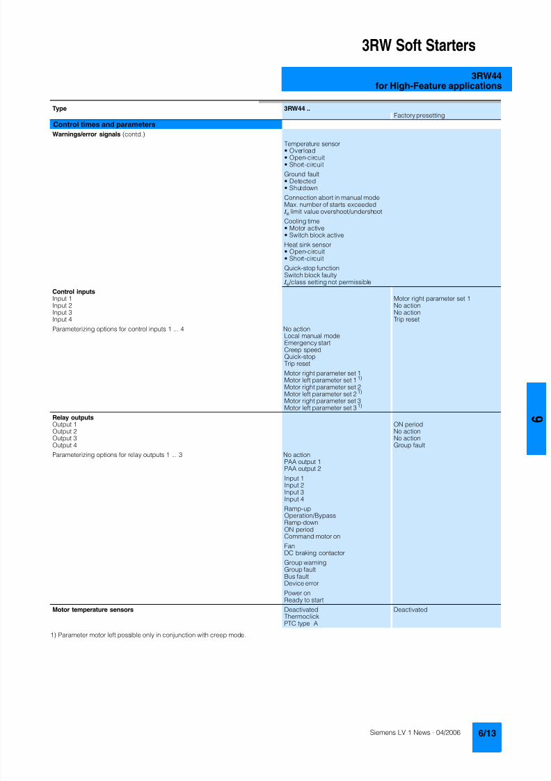
8122019 Arr Estado Solido
httpslidepdfcomreaderfullarr-estado-solido 1740
3RW Soft Starters
3RW44for High-Feature applications
1) Parameter motor left possible only in conjunction with creep mode
Type 3RW44 Factory presetting
Control times and parameters
Warningserror signals (contd)Temperature sensorbull Overloadbull Open-circuitbull Short-circuit
Ground faultbull Detectedbull Shutdown
Connection abort in manual modeMax number of starts exceeded I e limit value overshootundershoot
Cooling timebull Motor activebull Switch block active
Heat sink sensorbull Open-circuitbull Short-circuit
Quick-stop functionSwitch block faulty I e class setting not permissible
Control inputsInput 1 Motor right parameter set 1Input 2 No actionInput 3 No actionInput 4 Trip reset
Parameterizing options for control inputs 1 4 No actionLocal manual modeEmergency startCreep speedQuick-stopTrip reset
Motor right parameter set 1Motor left parameter set 11) Motor right parameter set 2Motor left parameter set 21) Motor right parameter set 3Motor left parameter set 31)
Relay outputsOutput 1 ON periodOutput 2 No actionOutput 3 No actionOutput 4 Group fault
Parameterizing options for relay outputs 1 3 No actionPAA output 1PAA output 2
Input 1Input 2Input 3Input 4
Ramp-upOperationBypassRamp-downON periodCommand motor on
FanDC braking contactor
Group warningGroup faultBus faultDevice error
Power onReady to start
Motor temperature sensors Deactivated DeactivatedThermoclickPTC type A
8122019 Arr Estado Solido
httpslidepdfcomreaderfullarr-estado-solido 1840
3RW Soft Starters
3RW44for High-Feature applications
1) Current limit on soft starter set to 350 I M
2) For intermittent duty S4 with ON period = 70 T u = 40 degC stand-aloneinstallation vertical The quoted operating frequencies do not apply forautomatic mode
3) Maximum adjustable rated motor current I M dependent on CLASS setting
Type 3RW44 -BC4 3RW44 -BC5 3RW44 -BC6
Power electronics
Rated operational voltage for inline circuit V 200 460 AC 400 600 AC 400 690 AC
Tolerance -15+10 -15+10 -15+10Rated operational voltage for inside-delta circuit V 200 460 AC 400 600 AC 400 600 ACTolerance -15+10 -15+10 -15+10
Rated frequency Hz 50 60Tolerance plusmn10
Continuous operation at 40 degC ( of I e) 115
Minimum load ( of set motor current I M) 8
Maximum conductor length between soft starter and motor m 200
Permissible installation height m 5000 (derating from 1000 see characteristics) higher on request
Permissible mounting position
Permissible ambient temperatureOperation degC 0 +60 (derating from +40)Storage degC -25 +80
Degree of protection IP00
Type 3RW44 22 3RW44 23 3RW44 24 3RW44 25 3RW44 26 3RW44 27
Power electronics
Rated operational current I e 29 36 47 57 77 93
Load rating with rated operational current I ebull Acc to IEC and ULCSA for individual mounting
at 405060 degC AC-53a A 292623 363229 474237 575145 776859 938272
Smallest adjustable rated motor current I Mfor the motor overload protection
A 5 7 9 11 15 18
Power lossbull In operation after completed ramp-up with uninterrupted rated
operational current (40 degC) approx W 8 10 32 36 45 55bull During starting with current limit set to 350 I M (40 degC) W 400 470 600 725 940 1160
Permissible rated motor current and starts per hour
bull Normal starting (Class 5)- Rated motor current I M
1) starting time 5 s A 29 36 47 57 77 93- Starts per hour2) 1h 41 34 41 41 41 41
- Rated motor current I M1)3) starting time 10 s A 29 36 47 57 77 93
- Starts per hour2) 1h 20 15 20 20 20 20
bull Normal starting (Class 10)- Rated motor current I M
1) starting time 10 s A 29 36 47 57 77 93- Starts per hour2) 1h 20 15 20 20 20 20
- Rated motor current I M1)3) starting time 20 s A 29 36 47 57 77 93
- Starts per hour2) 1h 10 6 10 10 8 8
bull Normal starting (Class 15)- Rated motor current I M
1) starting time 15 s A 29 36 47 57 77 93- Starts per hour2) 1h 13 9 13 13 13 13
- Rated motor current I M1)3) starting time 30 s A 29 36 47 57 77 93
- Starts per hour2) 1h 6 4 6 6 6 6
bull For heavy starting (Class 20)- Rated motor current I M
1) starting time 20 s A 29 36 47 57 73 88- Starts per hour2) 1h 10 6 10 10 10 10
- Rated motor current I M1)3) starting time 40 s A 29 36 47 57 73 88
- Starts per hour2) 1h 4 2 4 5 18 08
bull For very heavy starting (Class 30)- Rated motor current I M
1) starting time 30 s A 29 36 44 57 65 77- Starts per hour2) 1h 6 4 6 6 6 6
- Rated motor current I M1)3) starting time 60 s A 29 36 44 57 65 77
- Starts per hour2) 1h 18 08 33 15 2 1
8122019 Arr Estado Solido
httpslidepdfcomreaderfullarr-estado-solido 1940
3RW Soft Starters
3RW44for High-Feature applications
1) Current limit on soft starter set to 350 I M
2) For intermittent duty S4 with ON period = 70 T u = 40 degC stand-aloneinstallation vertical The quoted operating frequencies do not apply forautomatic mode
3) Maximum adjustable rated motor current I M dependent on CLASS setting
Type 3RW44 34 3RW44 35 3RW44 36
Power electronics
Rated operational current I e 113 134 162
Load rating with rated operational current I ebull Acc to IEC and ULCSA for individual mounting AC-53a
- at 40 degC A 113 134 162- at 50 degC A 100 117 145- at 60 degC A 88 100 125
Smallest adjustable rated motor current I Mfor the motor overload protection
A 22 26 32
Power lossbull In operation after completed ramp-up with uninterrupted rated
operational current (40 degC) approx W 64 76 95bull During starting with current limit set to 350 I M (40 degC) W 1350 1700 2460
Permissible rated motor current and starts per hour
bull Normal starting (Class 5)- Rated motor current I M
1) starting time 5 s A 113 134 162- Starts per hour2) 1h 41 39 41
- Rated motor current I M1)3) starting time 10 s A 113 134 162
- Starts per hour2) 1h 20 15 20
bull Normal starting (Class 10)- Rated motor current I M
1) starting time 10 s A 113 134 162- Starts per hour2) 1h 20 15 20
- Rated motor current I M1)3) starting time 20 s A 113 134 162
- Starts per hour2) 1h 9 6 7
bull Normal starting (Class 15)- Rated motor current I M
1) starting time 15 s A 113 134 162- Starts per hour2) 1h 13 9 12
- Rated motor current I M1)3) starting time 30 s A 113 134 162
- Starts per hour2) 1h 6 6 1
bull For heavy starting (Class 20)- Rated motor current I M
1) starting time 20 s A 106 125 147- Starts per hour2) 1h 9 9 10
- Rated motor current I M1)3) starting time 40 s A 106 125 147
- Starts per hour2) 1h 15 2 1
bull For very heavy starting (Class 30)- Rated motor current I M
1) starting time 30 s A 91 110 120
- Starts per hour2) 1h 6 6 6- Rated motor current I M
1)3) starting time 60 s A 91 110 120- Starts per hour2) 1h 2 2 2
8122019 Arr Estado Solido
httpslidepdfcomreaderfullarr-estado-solido 2040
3RW Soft Starters
3RW44for High-Feature applications
1) Current limit on soft starter set to 350 I M
2) For intermittent duty S4 with ON period = 70 T u = 40 degC stand-aloneinstallation vertical The quoted operating frequencies do not apply forautomatic mode
3) Maximum adjustable rated motor current I M dependent on CLASS setting
Type 3RW44 43 3RW44 44 3RW44 45 3RW44 46 3RW44 47
Power electronics
Rated operational current I e 203 250 313 356 432
Load rating with rated operational current I ebull Acc to IEC and ULCSA for individual mounting AC-53a
- at 40 degC A 203 250 313 356 432- at 50 degC A 180 215 280 315 385- at 60 degC A 156 185 250 280 335
Smallest adjustable rated motor current I Mfor the motor overload protection
A 40 50 62 71 86
Power lossbull In operation after completed ramp-up with uninterrupted rated
operational current (40 degC) approx W 89 110 145 174 232bull During starting with current limit set to 350 I M (40 degC) W 3350 4000 4470 5350 5860
Permissible rated motor current and starts per hour
bull Normal starting (Class 5)- Rated motor current I M
1) starting time 5 s A 203 250 313 356 432- Starts per hour2) 1h 41 41 41 41 39
- Rated motor current I M1)3) starting time 10 s A 203 250 313 356 432
- Starts per hour2) 1h 20 20 19 17 16
bull Normal starting (Class 10)- Rated motor current I M
1) starting time 10 s A 203 250 313 356 432- Starts per hour2) 1h 20 20 19 17 16
- Rated motor current I M1)3) starting time 20 s A 203 250 313 356 432
- Starts per hour2) 1h 9 10 6 4 5
bull Normal starting (Class 15)- Rated motor current I M
1) starting time 15 s A 203 240 313 325 402- Starts per hour2) 1h 13 13 10 13 11
- Rated motor current I M1)3) starting time 30 s A 203 240 313 325 402
- Starts per hour2) 1h 3 6 1 2 1
bull For heavy starting (Class 20)- Rated motor current I M
1) starting time 20 s A 195 215 275 285 356- Starts per hour2) 1h 10 10 10 10 10
- Rated motor current I M1)3) starting time 40 s A 195 215 275 285 356
- Starts per hour2) 1h 1 5 1 3 1
bull For very heavy starting (Class 30)- Rated motor current I M
1) starting time 30 s A 162 180 220 240 285
- Starts per hour2) 1h 6 6 6 6 6- Rated motor current I M
1)3) starting time 60 s A 162 180 220 240 285- Starts per hour2) 1h 3 3 3 2 1
8122019 Arr Estado Solido
httpslidepdfcomreaderfullarr-estado-solido 2140
3RW Soft Starters
3RW44for High-Feature applications
1) Current limit on soft starter set to 350 I M
2) For intermittent duty S4 with ON period = 70 T u = 40 degC stand-aloneinstallation vertical The quoted operating frequencies do not apply forautomatic mode
3) Maximum adjustable rated motor current I M dependent on CLASS setting
Type 3RW44 53 3RW44 54 3RW44 55 3RW44 56 3RW44 57 3RW44 58
Power electronics
Rated operational current I e 551 615 693 780 880 970
Load rating with rated operational current I ebull Acc to IEC and ULCSA for individual mounting AC-53a
- at 40 degC A 551 615 693 780 880 970- at 50 degC A 494 551 615 693 780 850- at 60 degC A 438 489 551 615 693 760
Smallest adjustable rated motor current I Mfor the motor overload protection
A 110 123 138 156 176 194
Power lossbull In operation after completed ramp-up with uninterrupted rated
operational current (40 degC) approx W 159 186 220 214 250 270bull During starting with current limit set to 350 I M (40 degC) W 7020 8100 9500 11100 13100 15000
Permissible rated motor current and starts per hour
bull Normal starting (Class 5)- Rated motor current I M
1) starting time 5 s A 551 615 693 780 880 970- Starts per hour2) 1h 41 41 37 33 22 17
- Rated motor current I M1)3) starting time 10 s A 551 615 693 780 880 970
- Starts per hour2) 1h 20 20 16 13 8 5
bull Normal starting (Class 10)- Rated motor current I M
1) starting time 10 s A 551 615 693 780 880 970- Starts per hour2) 1h 20 20 16 13 8 5
- Rated motor current I M1)3) starting time 20 s A 551 615 693 780 880 970
- Starts per hour2) 1h 10 9 6 4 03 03
bull Normal starting (Class 15)- Rated motor current I M
1) starting time 15 s A 551 615 666 723 780 821- Starts per hour2) 1h 13 13 11 9 8 8
- Rated motor current I M1)3) starting time 30 s A 551 615 666 723 780 821
- Starts per hour2) 1h 6 4 3 1 04 05
bull For heavy starting (Class 20)- Rated motor current I M
1) starting time 20 s A 551 591 633 670 710 740- Starts per hour2) 1h 10 10 7 8 8 9
- Rated motor current I M1)3) starting time 40 s A 551 591 633 670 710 740
- Starts per hour2) 1h 4 2 1 1 04 1
bull For very heavy starting (Class 30)- Rated motor current I M
1) starting time 30 s A 500 525 551 575 600 630
- Starts per hour2) 1h 6 6 6 6 6 6- Rated motor current I M
1)3) starting time 60 s A 500 525 551 575 600 630- Starts per hour2) 1h 2 1 1 1 15 1
8122019 Arr Estado Solido
httpslidepdfcomreaderfullarr-estado-solido 2240
3RW Soft Starters
3RW44for High-Feature applications
1) When connecting cable lugs to DIN 46235 use 3RT19 56-4EA1 terminalcover for conductor cross-sections from 95 mmsup2 to ensure phase spacing
2) When connecting cable lugs to DIN 46234 the 3RT19 66-4EA1 terminalcover must be used for conductor cross-sections of 240 mmsup2 and more aswell as DIN 46235 for conductor cross-sections of 185 mmsup2 and more tokeep the phase clearance
Type 3RW44 2 3RW44 3 3RW44 4 3RW44 5
Conductor cross-sections
Screw
terminals
Main conductors
with box terminal 3RT19 55-4G (55 kW) 3RT19 66-4G
Front clampingpoint connected
bull Finely stranded with end sleeve mm2 16 70 70 240bull Finely stranded without end sleeve mm2 16 70 70 240bull Stranded mm2 16 70 95 300
bull Ribbon cable conductors(number x width x thickness)
mm min 3 x 9 x 08max 6 x 155 x 08
min 6 x 9 x 08max 20 x 24 x 05
bull AWG conductors solid or stranded AWG 6 20 30 600 kcmil
Rear clamping pointconnected
bull Finely stranded with end sleeve mm2 16 70 120 185bull Finely stranded without end sleeve mm2 16 70 120 185bull Stranded mm2 16 70 120 240
bull Ribbon cable conductors(number x width x thickness)
mm min 3 x 9 x 08max 6 x 155 x 08
min 6 x 9 x 08max 20 x 24 x 05
bull AWG conductors solid or stranded AWG 6 20 250 500 kcmil
Both clamping
points connected
bull Finely stranded with end sleeve mm2 max 1 x 50 1 x 70 min 2 x 50 max 2 x 185
bull Finely stranded without end sleeve mm2 max 1 x 50 1 x 70 min 2 x 50 max 2 x 185bull Stranded mm2 max 2 x 70 max 2 x 70 max 2 x 240
bull Ribbon cable conductors(number x width x thickness)
mm max 2 x (6 x 155 x 08) max 2 x (20 x 24 x 05)
bull AWG conductors solid or stranded AWG max 2 x 10 min 2 x 20max 2 x 500 kcmil
bull Terminal screws M10 (hexagon socket AF4) M12 (hexagon socket AF5)- Pickup torque 10 12 20 22
90 110 180 195
Screwterminals
Main conductors
with box terminal 3RT19 56-4G
Front or rear clamp-ing point connected
bull Finely stranded with end sleeve mm2 16 120bull Finely stranded without end sleeve mm2 16 120bull Stranded mm2 16 120
bull Ribbon cable conductors(number x width x thickness)
mm min 3 x 9 x 08max 6 x 155 x 08
bull AWG conductors solid or stranded AWG 6 250 kcmil
Both clampingpoints connected
bull Finely stranded with end sleeve mm2 max 1 x 95 1 x 120bull Finely stranded without end sleeve mm2 max 1 x 95 1 x 120bull Stranded mm2 max 2 x 120
bull Ribbon cable conductors(number x width x thickness)
mm max 2 x (10 x 155 x 08)
bull AWG conductors solid or stranded AWG max 2 x 30
Screwterminals
Main conductors
Without box terminalrail connection
bull Finely stranded with cable lug mm2 16 951) 50 2402) 50 2402)
bull Stranded with cable lug mm2 25 1201) 70 2402) 70 2402)
bull AWG conductors solid or stranded AWG 4 250 kcmil 20 500 kcmil 10 500 kcmil
bull Connecting bar (max width) mm 17 25 60
bull Terminal screws M8 x 25 (AF13) M10 x 30 (AF17) M12 x 40- Pickup torque NM 10 14 14 24 20 35lbin 89 124 124 210 177 310
8122019 Arr Estado Solido
httpslidepdfcomreaderfullarr-estado-solido 2340
3RW Soft Starters
3RW44for High-Feature applications
Soft starters Type 3RW44
Conductor cross-sections
Auxiliary conductors (1 or 2 conductors can be connected)
Screw terminals
bull Solid mm2 2 x 05 25bull Finely stranded with end sleeve mm2 2 x 05 15
bull AWG cables- Solid or stranded AWG 2 x 20 14- Finely stranded with end sleeve AWG 2 x 20 16
bull Terminal screws- Pickup torque NM 07 09
lbin 7 8
Spring-loaded terminals
bull Solid mm2 2 x 025 25bull Finely stranded with end sleeve mm2 2 x 025 15bull AWG conductors solid or stranded AWG 2 x 24 14
Standard Parameters
Electromagnetic compatibility acc to EN 60947-4-2
EMC interference immunityElectrostatic discharge (ESD) EN 61000-4-2 plusmn4 kV contact discharge plusmn8 kV air discharge
Electromagnetic RF fields EN 61000-4-3 Frequency range 80 1000 MHz with 80 at 1 kHzDegree of severity 3 10 Vm
Conducted RF interference EN 61000-4-6 Frequency range 150 kHz 80 MHz with 80 at 1 kHzInterference 10 V
RF voltages and RF currents on conductorsBurst EN 61000-4-4 plusmn2 kV5 kHzSurge EN 61000-4-5 plusmn1 kV line to line
plusmn2 kV line to ground
EMC interference emission
EMC interference field strength EN55011 Limit value of Class A at 30 1000 MHz
Radio interference voltage EN55011 Limit value of Class A at 015 30 MHz
Is an RI suppression filter necessary
Degree of noise suppression A (industrial applications) no
8122019 Arr Estado Solido
httpslidepdfcomreaderfullarr-estado-solido 2440
3RW Soft Starters
3RW44for High-Feature applications
Fuse assignment
The coordination type to which the motor feeder with soft starteris mounted depends on the application-specific requirements
Normally fuseless mounting (combination of motor starter pro-tector and soft starter) is sufficient If type 2 coordination is to befulfilled semiconductor fuses must be fitted in the motor feeder
1) The rated motor current must be considered when selecting the devices
2) The types of coordination are explained in more detail in theTechnical information LV 1 T under ndash Fuseless Load Feeders
Inline circuit fuseless version
Soft starters Motor starter protectorscircuit-breakers1)
Rated current 440 V +10 Rated currentG1 Q1Type A Type A
Type of coordination 12) 3RW44 22 3RW44 27 I q = 32 kA 3RW44 34 and 3RW44 35 I q = 16 kA 3RW44 36 3RW44 57 I q = 65 kA
3RW44 22 29 3RV10 42-4HA10 503RW44 23 36 3RV10 42-4JA10 633RW44 24 47 3RV10 42-4KA10 75
3RW44 25 57 3RV10 42-4LA10 903RW44 26 77 3RV10 42-4MA10 1003RW44 27 93 3RV10 42-4MA10 100
3RW44 34 113 3VL17 16-2DD36 1603RW44 35 134 3VL17 16-2DD36 1603RW44 36 162 3VL37 25-2DC36 250
3RW44 43 203 3VL47 31-3DC36 3153RW44 44 250 3VL47 31-3DC36 3153RW44 45 313 3VL47 40-3DC36 400
3RW44 46 356 3VL47 40-3DC36 4003RW44 47 432 3VL57 50-3DC36 500
3RW44 53 551 3VL67 80-3DE36 8003RW44 54 615 3VL67 80-3DE36 8003RW44 55 693 3VL67 80-3DE36 800
3RW44 56 780 3VL77 10-3AB36 10003RW44 57 880 3VL77 10-3AB36 10003RW44 58 970 3VL77 12-3AB36 1200
8122019 Arr Estado Solido
httpslidepdfcomreaderfullarr-estado-solido 2540
3RW Soft Starters
3RW44for High-Feature applications
1) If the ramp-down function Combined braking is selected no brakingcontactor is requiredIf the ramp-down function DC braking is selected a braking contactormust also be used (see table for type)For applications with large centrifugal masses (J Load gt J Motor) werecommend the function DC braking
2) Additional auxiliary relay K4LZXRT4A4T30(3RW44 soft starter with rated control supply voltage 230 V AC)LZXRT4A4S15(3RW44 soft starter with rated control supply voltage 115 V AC)
3) The types of coordination are explained in more detail in theTechnical information LV 1 T under ndash Fuseless Load Feeders
Inline circuit fused version (line protection only)
Soft starters Line protections Line contactorsup to 400 V
Braking contactors1)2)
Rated current 690 V +5 Rated current Size (optional) (for typical circuit see page 633)G1 F1 K1 K2 K3Type A Type A Type Type Type
Type of coordination 13) I q = 65 kA
3RW44 22 29 3NA3 820-6 50 00 3RT10 34 3RT15 26 --3RW44 23 36 3NA3 822-6 63 00 3RT10 35 3RT15 26 --
3RW44 24 47 3NA3 824-6 80 00 3RT10 36 3RT15 35 --3RW44 25 57 3NA3 830-6 100 00 3RT10 44 3RT15 35 --3RW44 26 77 3NA3 132-6 125 1 3RT10 45 3RT10 24 3RT10 353RW44 27 93 3NA3 136-6 160 1 3RT10 46 3RT10 25 3RT10 36
3RW44 34 113 3NA3 244-6 250 2 3RT10 54 3RT10 34 3RT10 443RW44 35 134 3NA3 244-6 250 2 3RT10 55 3RT10 36 3RT10 453RW44 36 162 3NA3 365-6 500 3 3RT10 56 3RT10 44 3RT10 45
3RW44 43 203 2 x 3NA3 354-6 2 x 355 3 3RT10 64 3RT10 44 3RT10 543RW44 44 250 2 x 3NA3 354-6 2 x 355 3 3RT10 65 3RT10 44 3RT10 553RW44 45 313 2 x 3NA3 365-6 2 x 500 3 3RT10 75 3RT10 54 3RT10 56
3RW44 46 356 2 x 3NA3 365-6 2 x 500 3 3RT10 75 3RT10 54 3RT10 563RW44 47 432 2 x 3NA3 365-6 2 x 500 3 3RT10 76 3RT10 55 3RT10 64
3RW44 53 551 2 x 3NA3 365-6 2 x 500 3 3TF68 44-0CM7 3TF68 44-0CM7 3TF68 44-0CM73RW44 54 615 2 x 3NA3 365-6 2 x 500 3 3TF68 44-0CM7 3TF68 44-0CM7 3TF68 44-0CM73RW44 55 693 2 x 3NA3 365-6 2 x 500 3 3TF69 44-0CM7 3TF69 44-0CM7 3TF69 44-0CM7
3RW44 56 780 2 x 3NA3 365-6 2 x 500 3 3TF69 44-0CM7 3TF69 44-0CM7 3TF69 44-0CM73RW44 57 880 2 x 3NA3 365-6 2 x 500 3 2 x 3TF69 44-0CM7 2 x 3TF69 44-0CM7 2 x 3TF69 44-0CM7
3RW44 58 970 3 x 3NA3 365-6 3 x 500 3
8122019 Arr Estado Solido
httpslidepdfcomreaderfullarr-estado-solido 2640
3RW Soft Starters
3RW44for High-Feature applications
1) If the ramp-down function Combined braking is selected no brakingcontactor is requiredIf the ramp-down function DC braking is selected a braking contactormust also be used (see table for type)For applications with large centrifugal masses (J Load gt J Motor) werecommend the function DC braking
2) Additional auxiliary relay K4LZXRT4A4T30(3RW44 soft starter with rated control supply voltage 230 V AC)LZXRT4A4S15(3RW44 soft starter with rated control supply voltage 115 V AC)
3) The types of coordination are explained in more detail in theTechnical information LV 1 T under ndash Fuseless Load Feeders
Inline circuit fused version with 3NE1 SITOR all-range fuse (semiconductor and line protection)
Soft starters All-range fuses Line contactors upto 400 V
Braking contactors1)2)
Ratedcurrent
Rated current Voltage Size (optional) (for typical circuit see page 633)
G1 Frsquo1 K1 K2 K3Type A Type A V Type Type Type
Type of coordination 23) I q = 65 kA
3RW44 22 29 3NE1 020-2 80 690 +5 00 3RT10 34 3RT15 26 --
3RW44 23 36 3NE1 020-2 80 690 +5 00 3RT10 35 3RT15 26 --3RW44 24 47 3NE1 021-2 100 690 +5 00 3RT10 36 3RT15 35 --
3RW44 25 57 3NE1 022-2 125 690 +5 00 3RT10 44 3RT15 35 --3RW44 26 77 3NE1 022-2 125 690 +5 00 3RT10 45 3RT10 24 3RT10 353RW44 27 93 3NE1 024-2 160 690 +5 1 3RT10 46 3RT10 25 3RT10 36
3RW44 34 113 3NE1 225-2 200 690 +5 1 3RT10 54 3RT10 34 3RT10 443RW44 35 134 3NE1 227-2 250 690 +5 1 3RT10 55 3RT10 36 3RT10 453RW44 36 162 3NE1 227-2 250 690 +5 1 3RT10 56 3RT10 44 3RT10 45
3RW44 43 203 3NE1 230-2 315 600 +10 1 3RT10 64 3RT10 44 3RT10 543RW44 44 250 3NE1 331-2 350 460 +10 2 3RT10 65 3RT10 44 3RT10 553RW44 45 313 3NE1 333-2 450 690 +5 2 3RT10 75 3RT10 54 3RT10 56
3RW44 46 356 3NE1 334-2 500 690 +5 2 3RT10 75 3RT10 54 3RT10 563RW44 47 432 3NE1 435-2 560 690 +5 3 3RT10 76 3RT10 55 3RT10 64
3RW44 53 551 2 x 3NE1 334-2 500 690 +10 2 3TF68 44-0CM7 3TF68 44-0CM7 3TF68 44-0CM73RW44 54 615 2 x 3NE1 334-2 500 690 +10 2 3TF68 44-0CM7 3TF68 44-0CM7 3TF68 44-0CM73RW44 55 693 2 x 3NE1 334-2 500 690 +10 2 3TF69 44-0CM7 3TF69 44-0CM7 3TF69 44-0CM7
3RW44 56 780 2 x 3NE1 435-2 560 690 +10 3 3TF69 44-0CM7 3TF69 44-0CM7 3TF69 44-0CM7
3RW44 57 880 2 x 3NE1 435-2 560 690 +10 3 2 x 3TF69 44-0CM7 2 x 3TF69 44-0CM7 2 x 3TF69 44-0CM73RW44 58 970 2 x 3NE1 435-2 560 690 +10 3
8122019 Arr Estado Solido
httpslidepdfcomreaderfullarr-estado-solido 2740
3RW Soft Starters
3RW44for High-Feature applications
1) If the ramp-down function Combined braking is selected no brakingcontactor is requiredIf the ramp-down function DC braking is selected a braking contactor
must also be used (see table for type)For applications with large centrifugal masses (J Load gt J Motor) werecommend the function DC braking
2) Additional auxiliary relay K4LZXRT4A4T30(3RW44 soft starter with rated control supply voltage 230 V AC)
LZXRT4A4S15(3RW44 soft starter with rated control supply voltage 115 V AC)
3) The types of coordination are explained in more detail in theTechnical information LV 1 T under ndash Fuseless Load Feeders
Inline circuit fused version with 3NE or 3NC SITOR semiconductor fuse(semiconductor protection by fuse lead and overload protection by circuit-breaker)
Soft starters Semiconductor fuses minimum Semiconductor fuses maximum Semiconductor fuses (cylinder)
Ratedcurrent
Rated current Size Rated current Size Rated current Size
G1 F3 F3 F3Type A Type A Type A Type A
Type of coordination 23) I q = 65 kA
3RW44 22 29 3NE4 120 80 0 3NE4 121 100 0 3NC2 280 80 22 x 58
3RW44 23 36 3NE4 121 100 0 3NE4 122 125 0 3NC2 200 100 22 x 583RW44 24 47 3NE4 121 100 0 3NE4 122 125 0 3NC2 200 100 22 x 58
3RW44 25 57 3NE4 122 125 0 3NE4 124 160 03RW44 26 77 3NE4 124 160 0 3NE4 124 160 03RW44 27 93 3NE3 224 160 1 3NE3 333 450 2
3RW44 34 113 3NE3 225 200 1 3NE3 335 560 23RW44 35 134 3NE3 225 200 1 3NE3 335 560 23RW44 36 162 3NE3 227 250 1 3NE3 333 450 2
3RW44 43 203 3NE3 230-0B 315 1 3NE3 333 450 23RW44 44 250 3NE3 230-0B 315 1 3NE3 333 450 23RW44 45 313 3NE3 233 450 1 3NE3 336 630 2
3RW44 46 356 3NE3 333 450 2 3NE3 336 630 23RW44 47 432 3NE3 335 560 2 3NE3 338-8 800 2
3RW44 53 551 2 x 3NE3 335 560 2 3 x 3NE3 334-0B 500 23RW44 54 615 2 x 3NE3 335 560 2 3 x 3NE3 334-0B 500 23RW44 55 693 2 x 3NE3 335 560 2 3 x 3NE3 334-0B 500 2
3RW44 56 780 2 x 3NE3 336 630 2 2 x 3NE3 340-8 900 2
3RW44 57 880 2 x 3NE3 336 630 2 2 x 3NE3 340-8 900 23RW44 58 970 2 x 3NE3 336 630 2 2 x 3NE3 340-8 900 2
Soft starters Line contactorsup to 400 V
Braking contactors1)2) Motor starter protectors circuit-breakers
Max line protection
Ratedcurrent
(optional) (for typical circuit see page 633) 440 V +10 Rated current 690 V +5 Rated current Size
G1 K1 Q1 F1Type A Type Type Type Type A Type A
Type of coordination 23) 3RW44 22 3RW44 27 I q = 32 kA 3RW44 34 and 3RW44 35 I q = 16 kA 3RW44 36 3RW44 57 I q = 65 kA
3RW44 22 29 3RT10 34 3RT15 26 -- 3RV10 41-4HA10 50 3NA3 820-6 50 003RW44 23 36 3RT10 35 3RT15 26 -- 3RV10 41-4JA10 63 3NA3 822-6 63 003RW44 24 47 3RT10 36 3RT15 35 -- 3RV10 41-4KA10 75 3NA3 824-6 80 00
3RW44 25 57 3RT10 44 3RT15 35 -- 3RV10 41-4LA10 90 3NA3 830-6 100 003RW44 26 77 3RT10 45 3RT10 24 3RT10 35 3RV10 41-4MA10 100 3NA3 132-6 125 13RW44 27 93 3RT10 46 3RT10 25 3RT10 36 3RV10 41-4MA10 100 3NA3 136-6 160 1
3RW44 34 113 3RT10 54 3RT10 34 3RT10 44 3VL17 16-1DD36 160 3NA3 244-6 250 2
3RW44 35 134 3RT10 55 3RT10 36 3RT10 45 3VL17 16-1DD36 160 3NA3 244-6 250 23RW44 36 162 3RT10 56 3RT10 44 3RT10 45 3VL37 25-1DC36 250 3NA3 365-6 500 3
3RW44 43 203 3RT10 64 3RT10 44 3RT10 54 3VL47 31-1DC36 315 2 x 3NA3 354-6 2 x 355 33RW44 44 250 3RT10 65 3RT10 44 3RT10 55 3VL47 31-1DC36 315 2 x 3NA3 354-6 2 x 355 33RW44 45 313 3RT10 75 3RT10 54 3RT10 56 3VL47 40-1DC36 400 2 x 3NA3 365-6 2 x 500 3
3RW44 46 356 3RT10 75 3RT10 54 3RT10 56 3VL47 40-1DC36 400 2 x 3NA3 365-6 2 x 500 33RW44 47 432 3RT10 76 3RT10 55 3RT10 64 3VL57 50-1DC36 500 2 x 3NA3 365-6 2 x 500 3
3RW44 53 551 3TF68 44-0CM7 3TF68 44-0CM7 3TF68 44-0CM7 3VL67 80-1AB36 800 2 x 3NA3 365-6 2 x 500 33RW44 54 615 3TF68 44-0CM7 3TF68 44-0CM7 3TF68 44-0CM7 3VL67 80-1AB36 800 2 x 3NA3 365-6 2 x 500 33RW44 55 693 3TF69 44-0CM7 3TF69 44-0CM7 3TF69 44-0CM7 3VL67 80-1AB36 800 2 x 3NA3 365-6 2 x 500 3
3RW44 56 780 3TF69 44-0CM7 3TF69 44-0CM7 3TF69 44-0CM7 3VL77 10-1AB36 1000 2 x 3NA3 365-6 2 x 500 33RW44 57 880 2 x
3TF69 44-0CM72 x3TF69 44-0CM7
2 x3TF69 44-0CM7
3VL77 10-1AB36 1000 2 x 3NA3 365-6 2 x 500 3
3RW44 58 970 3VL77 12-1AB36 1200 3 x 3NA3 365-6 3 x 500 3
8122019 Arr Estado Solido
httpslidepdfcomreaderfullarr-estado-solido 2840
3RW Soft Starters
3RW44for High-Feature applications
1) The types of coordination are explained in more detail in theTechnical information LV 1 T under ndash Fuseless Load FeedersThe type of coordination 2 only refers to soft starters not to feeder compo-nents ( I q = 65 kA)
Inside-delta circuit fused version with 3NE or 3NC SITOR fuses(semiconductor protection by fuse lead and overload protection by circuit-breaker)
Soft starters Semiconductor fuses minimum Semiconductor fuses maximum Semiconductor fuses (cylinder)
Ratedcurrent
Rated current Size Rated current Size Rated current Size
G1 F3 F3 F3Type A Type A Type A Type A
Type of coordination 21)
3RW44 22 50 3NE4 120 80 0 3NE4 121 100 0 3NC2 280 80 22 x 58
3RW44 23 62 3NE4 121 100 0 3NE4 122 125 0 3NC2 200 100 22 x 583RW44 24 81 3NE4 121 100 0 3NE4 122 125 0 3NC2 200 100 22 x 58
3RW44 25 99 3NE4 122 125 0 3NE4 124 160 03RW44 26 133 3NE4 124 160 0 3NE4 124 160 03RW44 27 161 3NE3 224 160 1 3NE3 333 450 2
3RW44 34 196 3NE3 225 200 1 3NE3 335 560 23RW44 35 232 3NE3 225 200 1 3NE3 335 560 23RW44 36 281 3NE3 227 250 1 3NE3 333 450 2
3RW44 43 352 3NE3 230-0B 315 1 3NE3 333 450 23RW44 44 433 3NE3 230-0B 315 1 3NE3 333 450 23RW44 45 542 3NE3 233 450 1 3NE3 336 630 2
3RW44 46 617 3NE3 333 450 2 3NE3 336 630 23RW44 47 748 3NE3 335 560 2 3NE3 338-8 800 2
3RW44 53 954 2 x 3NE3 335 560 2 3 x 3NE3 334-0B 500 23RW44 54 1065 2 x 3NE3 335 560 2 3 x 3NE3 334-0B 500 23RW44 55 1200 2 x 3NE3 335 560 2 3 x 3NE3 334-0B 500 2
3RW44 56 1351 2 x 3NE3 336 630 2 2 x 3NE3 340-8 900 2
3RW44 57 1524 2 x 3NE3 336 630 2 3 x 3NE3 340-8 900 23RW44 58 1680 2 x 3NE3 336 630 2 3 x 3NE3 340-8 900 2
Soft starters Line contactorsup to 400 V
Motor starter protectors cirduit-breakers
Line protections
Ratedcurrent
(optional) 440 V +10 Rated current 690 V +5 Rated current Size
G1 K1 Q1 F1Type A Type Type A Type A
Type of coordination 21)
3RW44 22 50 3RT10 36-1AP04 3RV10 4-4KA10 75 3NA3 824-6 80 003RW44 23 62 3RT10 44-1AP04 3RV10 4-4LA10 90 3NA3 830-6 100 003RW44 24 81 3RT10 46-1AP04 3RV10 4-4MA10 100 3NA3 132-6 125 1
3RW44 25 99 3RT10 54-1AP36 3VL27 16-DC36 160 3NA3 136-6 160 13RW44 26 133 3RT10 55-6AP36 3VL27 16-DC36 160 3NA3 240-6 200 23RW44 27 161 3RT10 56-6AP36 3VL37 20-DC36 200 3NA3 244-6 250 2
3RW44 34 196 3RT10 64-6AP36 3VL37 25-DC36 250 3NA3 360-6 400 3
3RW44 35 232 3RT10 65-6AP36 3VL47 31-DC36 315 3NA3 360-6 400 33RW44 36 281 3RT10 66-6AP36 3VL47 40-DC36 400 2 x 3NA3 360-6 2 x 400 3
3RW44 43 352 3RT10 75-6AP36 3VL47 40-DC36 400 2 x 3NA3 365-6 2 x 500 33RW44 44 433 3RT10 76-6AP36 3VL57 50-DC36 500 2 x 3NA3 365-6 2 x 500 33RW44 45 542 3TF68 44-0CM7 3VL57 63-DC36 800 3 x 3NA3 365-6 3 x 500 3
3RW44 46 617 3TF68 44-0CM7 3VL67 80-AB36 800 3 x 3NA3 365-6 3 x 500 33RW44 47 748 3TF69 3VL67 80-AB36 1000 3 x 3NA3 365-6 3 x 500 3
3RW44 53 954 2 x 3TF68 44-0CM7 3VL77 10-AB36 1000 3 x 3NA3 365-6 3 x 500 33RW44 54 1065 2 x 3TF68 44-0CM7 3VL77 12-AB36 1250 3 x 3NA3 365-6 3 x 500 33RW44 55 1200 2 x 3TF69 44-0CM7 3VL87 16-AB36 1600 3 x 3NA3 365-6 3 x 500 3
3RW44 56 1351 2 x 3TF69 44-0CM7 3VL87 16-AB36 1600 3 x 3NA3 372 3 x 630 33RW44 57 1524 2 x 3TF69 44-0CM7 3VL87 16-AB36 1600 3 x 3NA3 372 3 x 630 33RW44 58 1680 3WL12 20 2000 2 x 3NA3 480 2 x 1000 4
8122019 Arr Estado Solido
httpslidepdfcomreaderfullarr-estado-solido 2940
3RW Soft Starters
3RW44for High-Feature applications
Characteristic curves
Motor protection tripping characteristics for 3RW44(with symmetry)
Admissible mounting height
The admissible operational voltage is reduced to 460 V with a mountingheight of more than 2000 m
Motor protection characteristics for 3RW44(with phase unbalance)
e
2 4 6 101
Class 10 Class 15 Class 20
100
101
102
103
2
4
6
2
4
6
2
4
6
Class 5 Class 30
N S B 0
_ 0 1 5 0 0 a
[ s ]
x
T r i p p i n g t i m e
85
105
70
75
80
90
95
100
N S B 0
_ 0 1 7 0 4
0 1000 2000 3000 4000 5000 O p e r
a t i o n a
l r a
t e d c u r r e n
t I
i n
Mounting height in m
e
e
1001
Class 10 Class 15 Class 20
100
101
102
103
2
4
6
2
4
6
2
4
6
Class 5 Class 30
N S B 0
_ 0 1 7 0 6
[ s ]
x10
T r i p p
i n g
t i m e
8122019 Arr Estado Solido
httpslidepdfcomreaderfullarr-estado-solido 3040
3RW Soft Starters
3RW44for High-Feature applications
More information
Application examples for normal starting (Class 10)
Application examples for heavy starting (Class 20)
Application examples for very heavy starting (Class 30)
NoteThese tables present sample setting values and device sizesThey are intended only for the purposes of information and arenot binding The setting values depend on the application inquestion and must be optimized during commissioningThe soft starter dimensions should be checked where necessarywith the Win-Soft Starter software or with the help ofTechnical Assistance
Normal starting Class 10 (up to 20 s with 350 I n motor)The soft starter rating can be selected to be as high as the rating of the motor used
Application Conveyor belts Roller conveyors Compressors Small ventilators Pumps Hydraulic pumps
Starting parameters
bull Voltage ramp and currentlimiting- Starting voltage 70 60 50 30 30 30- Starting time s 10 10 10 10 10 10- Current limit value Deactivated Deactivated 4 x I M 4 x I M Deactivated Deactivated
bull Torque ramp- Starting torque 60 50 40 20 10 10- End torque 150 150 150 150 150 150- Starting time 10 10 10 10 10 10
bull Breakaway pulse Deactivated (0 ms) Deactivated (0 ms) Deactivated (0 ms) Deactivated (0 ms) Deactivated (0 ms) Deactivated (0 ms)
Ramp-down mode Smoothramp-down
Smoothramp-down
Free ramp-down Free ramp-down Pump ramp-down Free ramp-down
Heavy starting Class 20 (up to 40 s with 350 I n motor)The soft starter has to be selected one rating class higher than the motor used
Application Stirrers Centrifuges Milling machines
Starting parameters
bull Voltage ramp and currentlimiting- Starting voltage 30 30 30- Starting time s 30 30 30- Current limit value 4 x I M 4 x I M 4 x I M
bull Torque ramp- Starting torque 30 30 30- End torque 150 150 150- Starting time 30 30 30
bull Breakaway pulse Deactivated (0 ms) Deactivated (0 ms) Deactivated (0 ms)
Ramp-down mode Free ramp-down Free ramp-down Free ramp-down or DC braking
Very heavy starting Class 30 (up to 60 s with 350 I n motor)The soft starter has to be selected two rating classes higher than the motor used
Application Large ventilators Mills Breakers Circular sawbandsaws
Starting parameters
bull Voltage ramp and currentlimiting- Starting voltage 30 50 50 30- Starting time s 60 60 60 60- Current limit value 4 x I M 4 x I M 4 x I M 4 x I M
bull Torque ramp- Starting torque 20 50 50 20- End torque 150 150 150 150- Starting time 60 60 60 60
bull Breakaway pulse Deactivated (0 ms) 80 300 ms 80 300 ms Deactivated (0 ms)
Ramp-down mode Free ramp-down Free ramp-down Free ramp-down Free ramp-down
8122019 Arr Estado Solido
httpslidepdfcomreaderfullarr-estado-solido 3140
3RW Soft Starters
3RW44for High-Feature applications
Circuit concept
The SIRIUS 3RW44 soft starters can be operated in two differenttypes of circuit
bull Inline circuitThe controls for isolating and protecting the motor are simplyconnected in series with the soft starter The motor isconnected to the soft starter with three leads
bull Inside-delta circuitThe wiring is similar to that of wye-delta starters The phases ofthe soft starter are connected in series with the individual motorwindings The soft starter then only has to carry the phasecurrent amounting to about 58 of the rated motor current(conductor current)
Comparison of the types of circuit
Inline circuitRated current I e corresponds to the rated motor current I n3 leads to the motor
Inside-delta circuit
Rated current I e corresponds to approx 58 of the rated motorcurrent I n6 leads to the motor (as with wye-delta starters)
Which circuit
Using the inline circuit involves the lowest wiring complexityIf the soft starter to motor connections are long this contactsequence is preferableWith the inside-delta circuit there is double the wiring complexitybut a smaller size of device can be used at the same rating
Thanks to choosing the operational mode between the inline cir-cuit and inside-delta circuit the most favorable solution can al-ways be chosen
The braking function is possible only in the inline circuit
Configuration
The 3RW44 solid-state soft starters are designed for normalstarting In case of heavy starting or increased starting
frequency a larger device must be selectedFor long starting times it is recommended to have a PTC ther-mistor detector in the motor This also applies for the ramp-downmodes smooth ramp-down pump ramp-down and DC brakingbecause during the ramp-down time in these modes an addi-tional current loading applies in contrast to free ramp-down
In the motor feeder between the SIRIUS 3RW soft starter and themotor no capacitive elements are permitted (eg no reactive-power compensation equipment) In addition neither staticsystems for reactive-power compensation nor dynamic PFC(Power Factor Correction) must be operated in parallel duringstarting and ramp-down of the soft starter This is important toprevent faults arising on the compensation equipment andor thesoft starter
All elements of the main circuit (such as fuses and controls)
should be dimensioned for direct starting following the localshort-circuit conditions Fuses switching devices and overloadrelays must be ordered separately
The harmonic component load for starting currents must betaken into consideration for the selection of motor starterprotectors (selection of release)
NoteWhen switching on three-phase current motors voltage dropsnormally will occur with all types of starters (direct starters star- delta starters soft starters) On principle the feeding transformermust be configured such that when starting the motor thevoltage drop must occur within the admissible tolerance Whenthe feeding transformer is designed quite scarce the control vol- tage (being independent of the main voltage) should be sup- plied with a separate circuit in order to prevent the soft starterfrom switching off
Serial PC interface PROFIBUS DP communication moduleand parameterizing and operating software Soft Starter ES
The solid-state 3RW44 soft starters have a PC interface forcommunicating with the Soft Starter ES 2006 Smart software orto be connected to an external operating and monitoring mod-ule When using the optional communication module PROFIBUSthe 3RW44 soft starter can be connected to the PROFIBUS netand can communicate via GSD file or software Soft Starter ES2006 Professional
Manual for SIRIUS 3RW44
Besides containing all important information on planning com-missioning and servicing the manual also contains suggestedcircuits and the technical specifications for all devices
Win-Soft Starter selection and simulation program
With this software you can simulate and select all Siemens softstarters taking into account various parameters such as mainsproperties motor and load data and special applicationrequirements
The software is a valuable tool which makes complicatedlengthy manual calculations for determining the required softstarters superfluous
You can order the CD-ROM under the following order numberOrder No E20001-D1020-P302-V2-7400
More information can be found on the Internet athttpwwwsiemenscomsoftstarter
8122019 Arr Estado Solido
httpslidepdfcomreaderfullarr-estado-solido 3240
3RW Soft Starters
3RW44for High-Feature applications
SIRIUS soft starter training course (SD-SIRIUSO)
Siemens offers a 2-day training course on the SIRIUS solid-statesoft starters to keep customers and own personnel up-to-date on
configuring commissioning and servicing issuesPlease direct enquiries and applications to
AampD PT 4 (Trainings-Center Erlangen)Werner-von-Siemens-Str 65D-91052 ErlangenTelefon ++49 9131 729262Telefax ++49 9131 728172sibrainindustrysiemenscomhttp wwwsiemenscomsitrain
8122019 Arr Estado Solido
httpslidepdfcomreaderfullarr-estado-solido 3340
3RW Soft Starters
Project planning aids
Dimensional drawings
3RW44 2 3RW44 3 and 3RW44 4 for High-Feature applications
TypeDimension(mm)
a b c d e f g h I k l m n o p q
3RW44 2 180 170 37 11 167 100 240 270 180 148 75 153 7 184 66 M6 10 Nm
3RW44 3 180 170 37 17 167 100 240 270 180 148 75 153 7 198 9 M6 10 Nm
3RW44 4 210 210 48 25 190 140 269 298 205 166 16 166 9 230 11 M8 15 Nm
8122019 Arr Estado Solido
httpslidepdfcomreaderfullarr-estado-solido 3440
3RW Soft Starters
Project planning aids
3RW44 5 for High-Feature applications
147
173
195
118
N S B 0_
0 1 6 5 3
261
290
249
162
152
6 2 3
1 0 5
2 5 3
1 6 5
76
44
470
510
1
5 5
2
0Oslash14 40
6 3 8 5
5 9 0
8122019 Arr Estado Solido
httpslidepdfcomreaderfullarr-estado-solido 3540
3RW Soft Starters
Project planning aids
Schematics
1) Permissible values for main and control voltagesee Technical Specifications
3RW44 connection examples for main and control circuits
Main circuit Control circuitPossibility 1a Possibility 1Inline circuit with circuit-breaker and SITOR fuse(semiconductor protection only)
Control by pushbutton
Main circuit
Possibility 1b Possibility 1cInline circuit with full-rangeprotection (line andsemiconductor protection)
Inline circuit with line andSITOR fuse(semiconductor protection only)
Q1
L3L2L1
G1
F3
T1 T2 T3
M1
N S B 0_
0 1 4 9 0 a
L1 L2 L3
V1U1 W1
MPE 3~
3NPE 400 V AC 50 Hz
(optionalsemiconductorprotection fuse)
13 14 23 24 33 34 95 9896 +
T1 T2IN4IN3IN2IN1L-L+A1
A2
NPE
PE
G1
F2
NSB0_01494a
S t a r t
S 2
R e s e t S
3
StopS1
L1
On periodGrouperror
N o a c t i o n
N o a c t i o n
Noaction
PTC type Aor
Thermoclick
Noaction
1NPE 230 V AC 50 Hz
M o t o r o
n r i g h t
P S
1
1)
8122019 Arr Estado Solido
httpslidepdfcomreaderfullarr-estado-solido 3640
3RW Soft Starters
Project planning aids
1) Permissible values for main and control voltagesee Technical Specifications
2) Caution Risk of restartingThe start command (eg from the PLC) must be reset prior to a resetcommand because a new automatic restart will take place automaticallyif a start command is active after the reset command This appliesespecially in case of motor protection trippingFor safety reasons we recommend incorporating the group error output(terminals 95 and 96) in the controller
Main circuit Control circuit
Possibility 2 Possibility 2Inline circuit with main contactor Control of a main contactor and control by means of PLC
Q1
L3L2L1
G1
K1
F3
L1 L2 L3
T1 T2 T3
M1
N S B 0_
0 1 4 9 5 a
V1U1 W1
MPE 3~
1)
(optionalsemiconductorprotection)
(optional linecontactor if floatingswitching of themotor is planned)
3NPE 400 V AC 50 Hz
13 14 23 24 33 34 95 9896+
T1 T2IN4IN3IN2IN1L-L+A1
A2
NPE
PE
G1
K1NSB0_01496a
F2+24 V DC
M
L1 1NPE AC 230 V 50 Hz1)
Switch-on duration
M o t o r r i g h t
T r i p R e s e t
PLC outputs PLC inputs
N o a c t i o n
N o a c t i o n
No action No action
Group error
PTC type A Thermoclick
(optional line contactorif floating switchingof the motor is planned)
P S 1
ResetStart 2)
8122019 Arr Estado Solido
httpslidepdfcomreaderfullarr-estado-solido 3740
3RW Soft Starters
Project planning aids
1) Permissible values for main and control voltagesee Technical Specifications
2) Caution Risk of restartingThe start command (eg from the PLC) must be reset prior to a resetcommand because a new automatic restart will take place automaticallyif a start command is active after the reset command This applies espe-cially in case of motor protection trippingFor safety reasons we recommend incorporating the group error output(terminals 95 and 96) in the controller
3) If the ramp-down function Combined braking is selected no brakingcontactor is requiredIf the ramp-down function DC braking is selected a braking contactormust be used in addition Type see Fuse Coordination (inline circuit) onpages 621 to 623For applications with large centrifugal masses (J Load gt J Motor) werecommend the function DC brakingThe output 2 must be switched over to DC braking contactor
4) Auxiliary relay K4 egLZXRT4A4T30 (230 V AC rated control supply voltage)LZXRT4A4S15 (115 V AC rated control supply voltage)
Main circuit Control circuit
Possibility 3a Possibility 3aInline circuit with ramp-down function DC braking3)
(for device types 3RW44 22 to 3RW44 25)Control of the braking contactor3)
Main circuit Control circuit
Possibility 3b Possibility 3bInline circuit with ramp-down function DC braking3)
(for device types 3RW44 26 to 3RW44 47)Control of the braking contactor3)
Q1
L3L2
G1
F3
T1 T2 T3
M1
N S B 0_
0 1 5 0 1 a
L1 L2 L3
V1U1 W1
M
K2 K2 K2
PE 3~
1)
2
(optionalsemi-conductorprotection)
L1 3NPE 400 V AC 50 Hz
13 14 23 24 33 34 95 9896 +
T1 T2IN4IN3IN2IN1L-L+A1
A2
NPE
PEG1
K2NSB0_01502
R e s e t
M Start Reset
+24 V DC
K2
F2
1)
2)
No action Group error
N o a c t i o n
N o a c t i o n
On period
PLC output
PTC type Aor
Thermoclick
L1 1NPE 230 V AC 50 Hz
DC braking contactor 3)
K2 K33 3
G1
F3
T1 T2 T3
M1
N S B 0_
0 1
5 0 3 a
L1 L2 L3
V1U1 W1
MPE 3~
Q1
L3L2
1)
(optionalsemi-conductorprotection)
L1 3NPE 400 V AC 50 Hz
13 14 23 24 33 34 95 9896 +
T1 T2IN4IN3IN2IN1L-L+A1
A2
NPE
PE
G1
K4
NSB0_01504
R e s e t
K4 K4
K3 K2
K2 K3
+24 V DC
M Start Reset
F2
1)
2)
4)
PLC output
No action Group error
N o a c t i o n
N o a c t i o n
ON period
PTC type Aor
Thermoclick
M o t o r o n r i g h t
L1 1NPE 230 V AC 50 Hz
DC braking contactor 3)
8122019 Arr Estado Solido
httpslidepdfcomreaderfullarr-estado-solido 3840
3RW Soft Starters
Notes
1) Permissible values for main and control voltagesee Technical Specifications
2) Caution Risk of restartingThe start command (eg from the PLC) must be reset prior to a resetcommand because a new automatic restart will take place automaticallyif a start command is active after the reset command This appliesespecially in case of motor protection trippingFor safety reasons we recommend incorporating the group error output(terminals 95 and 96) in the controller
Main circuit Control circuit
Possibility 4a Possibility 4b Possibility 4Inside-delta circuit Change of direction of rotation for
inside-delta circuitControl by means of PLC
13 14 23 24 33 34 95 9896+
T1 T2IN4IN3IN2IN1L-L+A1
A2
NPE
PEG1
NSB0_01498a
+24 V DC
M
F2
L1 1NPE AC 230 V 50 Hz1)
2)
R e s e t
Switch-onduration
No action
Group error
N o a c t i o n
N o a c t i o n
No action
PTC type A orThermoclick
M o t o r r i g h t
PLC outputs PLC inputs
Start Reset
7
8122019 Arr Estado Solido
httpslidepdfcomreaderfullarr-estado-solido 3940
Appendix
Conditions of sale and delivery
Terms and Conditions of Sale and Delivery
By using this catalog you can acquire hardware and softwareproducts described therein from the Siemens AG subject to the
following terms Please note The scope the quality and the con-ditions for supplies and services including software productsby any Siemens entity having a registered office outside of Ger-many shall be subject exclusively to the General Terms andConditions of the respective Siemens entity
For customers with a seat or registered office in theFederal Republic of Germany
The bdquoGeneral Terms of Paymentldquo as well as the bdquoGeneral Condi-tions for the Supply of Products and Services of the Electricaland Electronics Industryldquo shall apply
For software products the bdquoGeneral License Conditions for Soft-ware Products for Automation and Drives for Customers with aSeat or registered Office in Germanyldquo shall apply
For customers with a seat or registered office outside of
Germany The bdquoGeneral Terms of Paymentldquo as well as the bdquoGeneral Condi-tions for Supplies of Siemens Automation and Drives for Cus-tomers with a Seat or registered Office outside of Germanyldquo shallapply
For software products the bdquoGeneral License Conditions for Soft-ware Products for Automation and Drives for Customers with aSeat or registered Office outside of Germanyldquo shall apply
General
The prices are in 991404 (Euro) ex works exclusive packaging
The sales tax (value added tax) is not included in the pricesIt shall be debited separately at the respective rate according tothe applicable legal regulations
In addition to the prices of products which include silver plump
aluminum andor copper surcharges may be calculated if therespective limits of the notes are exceeded The respective note(eg source German newspaper bdquoHandesblattldquo in categorybdquodeutsche Edelmetalleldquo and bdquoMetallverarbeiterldquo) for silver (bdquover-arbeitetes Silberldquo) plump (bdquoBlei in Kabelnldquo) aluminum (bdquoAlumin-ium in Kabelnldquo) and copper (bdquoElektrolytkupferldquo bdquoDEL-Notizldquo) re-spectively of the day the order or rather the on call order isreceived is decisive for the calculation of the surcharges
Surcharges of copper shall be calculated for Drives at a note(bdquoDEL-Notizldquo) above EUR 22500 100 Kg and for chokes trans-formers above EUR 15000 100 kg
Surcharges shall be charged based on the quantities of the ma-terials which are contained in the relevant products
Prices are subject to change without prior notice We will debitthe prices valid at the time of delivery
The dimensions are in mm In Germany according to the Ger-man law on units in measuring technology data in inches onlyapply to devices for export
Illustrations are not binding
Insofar as there are no remarks on the corresponding pages- especially with regard to data dimensions and weights given -these are subject to change without prior notice
Comprehensive Terms and Conditions of Sale and Delivery areavailable free of charge from your local Siemens business officeunder the following Order Nos
bull 6ZB5310-0KR30-0BA0(for customers based in the Federal Republic of Germany)
bull 6ZB5310-0KS53-0BA0(for customers based outside of theFederal Republic ofGermany)
or download them from the Internethttpwwwsiemenscomautomationmall (Germany AampD Mall Online-Help System)
Export regulations
The products listed in this catalog price list may be subject toEuropean German andor US export regulations
Therefore any export requiring a license is subject to approvalby the competent authorities
According to current provisions the following export regulations
must be observed with respect to the products featured in thiscatalog price list
Even without a label or with an ldquoAL Nldquo or ldquoECCN Nldquo authoriza-tion may be required due to the final destination and purpose forwhich the goods are to be used
The deciding factors are the AL or ECCN export authorizationindicated on order confirmations delivery notes and invoices
Errors excepted and subject to change without prior notice
AampDVuLEn 060306
AL Number of the German Export List
Products marked other than ldquoNldquo require an exportlicenseIn the case of software products the export des-ignations of the relevant data medium must alsobe generally adhered to
Goods labeled with an ldquoAL not equal to Nldquo aresubject to a European or German export authori-zation when being exported out of the EU
ECCN Export Control Classification Number
Products marked other than ldquoNldquo are subject to a
reexport license to specific countriesIn the case of software products the exportdesignations of the relevant data medium mustalso be generally adhered to
Goods labeled with an ldquoECCN not equal to Nldquo aresubject to a US re-export authorization
_ _ _ _
8122019 Arr Estado Solido
httpslidepdfcomreaderfullarr-estado-solido 4040
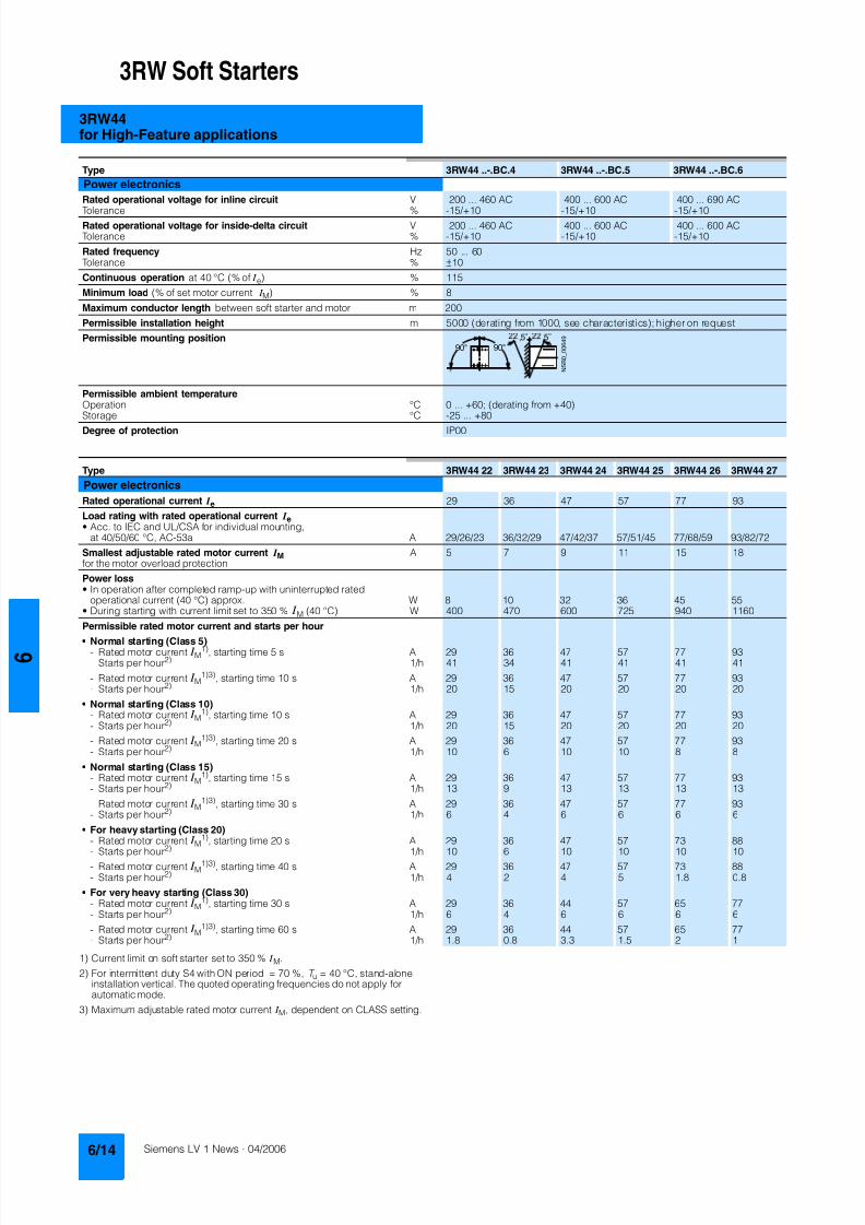
8122019 Arr Estado Solido
httpslidepdfcomreaderfullarr-estado-solido 1840
3RW Soft Starters
3RW44for High-Feature applications
1) Current limit on soft starter set to 350 I M
2) For intermittent duty S4 with ON period = 70 T u = 40 degC stand-aloneinstallation vertical The quoted operating frequencies do not apply forautomatic mode
3) Maximum adjustable rated motor current I M dependent on CLASS setting
Type 3RW44 -BC4 3RW44 -BC5 3RW44 -BC6
Power electronics
Rated operational voltage for inline circuit V 200 460 AC 400 600 AC 400 690 AC
Tolerance -15+10 -15+10 -15+10Rated operational voltage for inside-delta circuit V 200 460 AC 400 600 AC 400 600 ACTolerance -15+10 -15+10 -15+10
Rated frequency Hz 50 60Tolerance plusmn10
Continuous operation at 40 degC ( of I e) 115
Minimum load ( of set motor current I M) 8
Maximum conductor length between soft starter and motor m 200
Permissible installation height m 5000 (derating from 1000 see characteristics) higher on request
Permissible mounting position
Permissible ambient temperatureOperation degC 0 +60 (derating from +40)Storage degC -25 +80
Degree of protection IP00
Type 3RW44 22 3RW44 23 3RW44 24 3RW44 25 3RW44 26 3RW44 27
Power electronics
Rated operational current I e 29 36 47 57 77 93
Load rating with rated operational current I ebull Acc to IEC and ULCSA for individual mounting
at 405060 degC AC-53a A 292623 363229 474237 575145 776859 938272
Smallest adjustable rated motor current I Mfor the motor overload protection
A 5 7 9 11 15 18
Power lossbull In operation after completed ramp-up with uninterrupted rated
operational current (40 degC) approx W 8 10 32 36 45 55bull During starting with current limit set to 350 I M (40 degC) W 400 470 600 725 940 1160
Permissible rated motor current and starts per hour
bull Normal starting (Class 5)- Rated motor current I M
1) starting time 5 s A 29 36 47 57 77 93- Starts per hour2) 1h 41 34 41 41 41 41
- Rated motor current I M1)3) starting time 10 s A 29 36 47 57 77 93
- Starts per hour2) 1h 20 15 20 20 20 20
bull Normal starting (Class 10)- Rated motor current I M
1) starting time 10 s A 29 36 47 57 77 93- Starts per hour2) 1h 20 15 20 20 20 20
- Rated motor current I M1)3) starting time 20 s A 29 36 47 57 77 93
- Starts per hour2) 1h 10 6 10 10 8 8
bull Normal starting (Class 15)- Rated motor current I M
1) starting time 15 s A 29 36 47 57 77 93- Starts per hour2) 1h 13 9 13 13 13 13
- Rated motor current I M1)3) starting time 30 s A 29 36 47 57 77 93
- Starts per hour2) 1h 6 4 6 6 6 6
bull For heavy starting (Class 20)- Rated motor current I M
1) starting time 20 s A 29 36 47 57 73 88- Starts per hour2) 1h 10 6 10 10 10 10
- Rated motor current I M1)3) starting time 40 s A 29 36 47 57 73 88
- Starts per hour2) 1h 4 2 4 5 18 08
bull For very heavy starting (Class 30)- Rated motor current I M
1) starting time 30 s A 29 36 44 57 65 77- Starts per hour2) 1h 6 4 6 6 6 6
- Rated motor current I M1)3) starting time 60 s A 29 36 44 57 65 77
- Starts per hour2) 1h 18 08 33 15 2 1
8122019 Arr Estado Solido
httpslidepdfcomreaderfullarr-estado-solido 1940
3RW Soft Starters
3RW44for High-Feature applications
1) Current limit on soft starter set to 350 I M
2) For intermittent duty S4 with ON period = 70 T u = 40 degC stand-aloneinstallation vertical The quoted operating frequencies do not apply forautomatic mode
3) Maximum adjustable rated motor current I M dependent on CLASS setting
Type 3RW44 34 3RW44 35 3RW44 36
Power electronics
Rated operational current I e 113 134 162
Load rating with rated operational current I ebull Acc to IEC and ULCSA for individual mounting AC-53a
- at 40 degC A 113 134 162- at 50 degC A 100 117 145- at 60 degC A 88 100 125
Smallest adjustable rated motor current I Mfor the motor overload protection
A 22 26 32
Power lossbull In operation after completed ramp-up with uninterrupted rated
operational current (40 degC) approx W 64 76 95bull During starting with current limit set to 350 I M (40 degC) W 1350 1700 2460
Permissible rated motor current and starts per hour
bull Normal starting (Class 5)- Rated motor current I M
1) starting time 5 s A 113 134 162- Starts per hour2) 1h 41 39 41
- Rated motor current I M1)3) starting time 10 s A 113 134 162
- Starts per hour2) 1h 20 15 20
bull Normal starting (Class 10)- Rated motor current I M
1) starting time 10 s A 113 134 162- Starts per hour2) 1h 20 15 20
- Rated motor current I M1)3) starting time 20 s A 113 134 162
- Starts per hour2) 1h 9 6 7
bull Normal starting (Class 15)- Rated motor current I M
1) starting time 15 s A 113 134 162- Starts per hour2) 1h 13 9 12
- Rated motor current I M1)3) starting time 30 s A 113 134 162
- Starts per hour2) 1h 6 6 1
bull For heavy starting (Class 20)- Rated motor current I M
1) starting time 20 s A 106 125 147- Starts per hour2) 1h 9 9 10
- Rated motor current I M1)3) starting time 40 s A 106 125 147
- Starts per hour2) 1h 15 2 1
bull For very heavy starting (Class 30)- Rated motor current I M
1) starting time 30 s A 91 110 120
- Starts per hour2) 1h 6 6 6- Rated motor current I M
1)3) starting time 60 s A 91 110 120- Starts per hour2) 1h 2 2 2
8122019 Arr Estado Solido
httpslidepdfcomreaderfullarr-estado-solido 2040
3RW Soft Starters
3RW44for High-Feature applications
1) Current limit on soft starter set to 350 I M
2) For intermittent duty S4 with ON period = 70 T u = 40 degC stand-aloneinstallation vertical The quoted operating frequencies do not apply forautomatic mode
3) Maximum adjustable rated motor current I M dependent on CLASS setting
Type 3RW44 43 3RW44 44 3RW44 45 3RW44 46 3RW44 47
Power electronics
Rated operational current I e 203 250 313 356 432
Load rating with rated operational current I ebull Acc to IEC and ULCSA for individual mounting AC-53a
- at 40 degC A 203 250 313 356 432- at 50 degC A 180 215 280 315 385- at 60 degC A 156 185 250 280 335
Smallest adjustable rated motor current I Mfor the motor overload protection
A 40 50 62 71 86
Power lossbull In operation after completed ramp-up with uninterrupted rated
operational current (40 degC) approx W 89 110 145 174 232bull During starting with current limit set to 350 I M (40 degC) W 3350 4000 4470 5350 5860
Permissible rated motor current and starts per hour
bull Normal starting (Class 5)- Rated motor current I M
1) starting time 5 s A 203 250 313 356 432- Starts per hour2) 1h 41 41 41 41 39
- Rated motor current I M1)3) starting time 10 s A 203 250 313 356 432
- Starts per hour2) 1h 20 20 19 17 16
bull Normal starting (Class 10)- Rated motor current I M
1) starting time 10 s A 203 250 313 356 432- Starts per hour2) 1h 20 20 19 17 16
- Rated motor current I M1)3) starting time 20 s A 203 250 313 356 432
- Starts per hour2) 1h 9 10 6 4 5
bull Normal starting (Class 15)- Rated motor current I M
1) starting time 15 s A 203 240 313 325 402- Starts per hour2) 1h 13 13 10 13 11
- Rated motor current I M1)3) starting time 30 s A 203 240 313 325 402
- Starts per hour2) 1h 3 6 1 2 1
bull For heavy starting (Class 20)- Rated motor current I M
1) starting time 20 s A 195 215 275 285 356- Starts per hour2) 1h 10 10 10 10 10
- Rated motor current I M1)3) starting time 40 s A 195 215 275 285 356
- Starts per hour2) 1h 1 5 1 3 1
bull For very heavy starting (Class 30)- Rated motor current I M
1) starting time 30 s A 162 180 220 240 285
- Starts per hour2) 1h 6 6 6 6 6- Rated motor current I M
1)3) starting time 60 s A 162 180 220 240 285- Starts per hour2) 1h 3 3 3 2 1
8122019 Arr Estado Solido
httpslidepdfcomreaderfullarr-estado-solido 2140
3RW Soft Starters
3RW44for High-Feature applications
1) Current limit on soft starter set to 350 I M
2) For intermittent duty S4 with ON period = 70 T u = 40 degC stand-aloneinstallation vertical The quoted operating frequencies do not apply forautomatic mode
3) Maximum adjustable rated motor current I M dependent on CLASS setting
Type 3RW44 53 3RW44 54 3RW44 55 3RW44 56 3RW44 57 3RW44 58
Power electronics
Rated operational current I e 551 615 693 780 880 970
Load rating with rated operational current I ebull Acc to IEC and ULCSA for individual mounting AC-53a
- at 40 degC A 551 615 693 780 880 970- at 50 degC A 494 551 615 693 780 850- at 60 degC A 438 489 551 615 693 760
Smallest adjustable rated motor current I Mfor the motor overload protection
A 110 123 138 156 176 194
Power lossbull In operation after completed ramp-up with uninterrupted rated
operational current (40 degC) approx W 159 186 220 214 250 270bull During starting with current limit set to 350 I M (40 degC) W 7020 8100 9500 11100 13100 15000
Permissible rated motor current and starts per hour
bull Normal starting (Class 5)- Rated motor current I M
1) starting time 5 s A 551 615 693 780 880 970- Starts per hour2) 1h 41 41 37 33 22 17
- Rated motor current I M1)3) starting time 10 s A 551 615 693 780 880 970
- Starts per hour2) 1h 20 20 16 13 8 5
bull Normal starting (Class 10)- Rated motor current I M
1) starting time 10 s A 551 615 693 780 880 970- Starts per hour2) 1h 20 20 16 13 8 5
- Rated motor current I M1)3) starting time 20 s A 551 615 693 780 880 970
- Starts per hour2) 1h 10 9 6 4 03 03
bull Normal starting (Class 15)- Rated motor current I M
1) starting time 15 s A 551 615 666 723 780 821- Starts per hour2) 1h 13 13 11 9 8 8
- Rated motor current I M1)3) starting time 30 s A 551 615 666 723 780 821
- Starts per hour2) 1h 6 4 3 1 04 05
bull For heavy starting (Class 20)- Rated motor current I M
1) starting time 20 s A 551 591 633 670 710 740- Starts per hour2) 1h 10 10 7 8 8 9
- Rated motor current I M1)3) starting time 40 s A 551 591 633 670 710 740
- Starts per hour2) 1h 4 2 1 1 04 1
bull For very heavy starting (Class 30)- Rated motor current I M
1) starting time 30 s A 500 525 551 575 600 630
- Starts per hour2) 1h 6 6 6 6 6 6- Rated motor current I M
1)3) starting time 60 s A 500 525 551 575 600 630- Starts per hour2) 1h 2 1 1 1 15 1
8122019 Arr Estado Solido
httpslidepdfcomreaderfullarr-estado-solido 2240
3RW Soft Starters
3RW44for High-Feature applications
1) When connecting cable lugs to DIN 46235 use 3RT19 56-4EA1 terminalcover for conductor cross-sections from 95 mmsup2 to ensure phase spacing
2) When connecting cable lugs to DIN 46234 the 3RT19 66-4EA1 terminalcover must be used for conductor cross-sections of 240 mmsup2 and more aswell as DIN 46235 for conductor cross-sections of 185 mmsup2 and more tokeep the phase clearance
Type 3RW44 2 3RW44 3 3RW44 4 3RW44 5
Conductor cross-sections
Screw
terminals
Main conductors
with box terminal 3RT19 55-4G (55 kW) 3RT19 66-4G
Front clampingpoint connected
bull Finely stranded with end sleeve mm2 16 70 70 240bull Finely stranded without end sleeve mm2 16 70 70 240bull Stranded mm2 16 70 95 300
bull Ribbon cable conductors(number x width x thickness)
mm min 3 x 9 x 08max 6 x 155 x 08
min 6 x 9 x 08max 20 x 24 x 05
bull AWG conductors solid or stranded AWG 6 20 30 600 kcmil
Rear clamping pointconnected
bull Finely stranded with end sleeve mm2 16 70 120 185bull Finely stranded without end sleeve mm2 16 70 120 185bull Stranded mm2 16 70 120 240
bull Ribbon cable conductors(number x width x thickness)
mm min 3 x 9 x 08max 6 x 155 x 08
min 6 x 9 x 08max 20 x 24 x 05
bull AWG conductors solid or stranded AWG 6 20 250 500 kcmil
Both clamping
points connected
bull Finely stranded with end sleeve mm2 max 1 x 50 1 x 70 min 2 x 50 max 2 x 185
bull Finely stranded without end sleeve mm2 max 1 x 50 1 x 70 min 2 x 50 max 2 x 185bull Stranded mm2 max 2 x 70 max 2 x 70 max 2 x 240
bull Ribbon cable conductors(number x width x thickness)
mm max 2 x (6 x 155 x 08) max 2 x (20 x 24 x 05)
bull AWG conductors solid or stranded AWG max 2 x 10 min 2 x 20max 2 x 500 kcmil
bull Terminal screws M10 (hexagon socket AF4) M12 (hexagon socket AF5)- Pickup torque 10 12 20 22
90 110 180 195
Screwterminals
Main conductors
with box terminal 3RT19 56-4G
Front or rear clamp-ing point connected
bull Finely stranded with end sleeve mm2 16 120bull Finely stranded without end sleeve mm2 16 120bull Stranded mm2 16 120
bull Ribbon cable conductors(number x width x thickness)
mm min 3 x 9 x 08max 6 x 155 x 08
bull AWG conductors solid or stranded AWG 6 250 kcmil
Both clampingpoints connected
bull Finely stranded with end sleeve mm2 max 1 x 95 1 x 120bull Finely stranded without end sleeve mm2 max 1 x 95 1 x 120bull Stranded mm2 max 2 x 120
bull Ribbon cable conductors(number x width x thickness)
mm max 2 x (10 x 155 x 08)
bull AWG conductors solid or stranded AWG max 2 x 30
Screwterminals
Main conductors
Without box terminalrail connection
bull Finely stranded with cable lug mm2 16 951) 50 2402) 50 2402)
bull Stranded with cable lug mm2 25 1201) 70 2402) 70 2402)
bull AWG conductors solid or stranded AWG 4 250 kcmil 20 500 kcmil 10 500 kcmil
bull Connecting bar (max width) mm 17 25 60
bull Terminal screws M8 x 25 (AF13) M10 x 30 (AF17) M12 x 40- Pickup torque NM 10 14 14 24 20 35lbin 89 124 124 210 177 310
8122019 Arr Estado Solido
httpslidepdfcomreaderfullarr-estado-solido 2340
3RW Soft Starters
3RW44for High-Feature applications
Soft starters Type 3RW44
Conductor cross-sections
Auxiliary conductors (1 or 2 conductors can be connected)
Screw terminals
bull Solid mm2 2 x 05 25bull Finely stranded with end sleeve mm2 2 x 05 15
bull AWG cables- Solid or stranded AWG 2 x 20 14- Finely stranded with end sleeve AWG 2 x 20 16
bull Terminal screws- Pickup torque NM 07 09
lbin 7 8
Spring-loaded terminals
bull Solid mm2 2 x 025 25bull Finely stranded with end sleeve mm2 2 x 025 15bull AWG conductors solid or stranded AWG 2 x 24 14
Standard Parameters
Electromagnetic compatibility acc to EN 60947-4-2
EMC interference immunityElectrostatic discharge (ESD) EN 61000-4-2 plusmn4 kV contact discharge plusmn8 kV air discharge
Electromagnetic RF fields EN 61000-4-3 Frequency range 80 1000 MHz with 80 at 1 kHzDegree of severity 3 10 Vm
Conducted RF interference EN 61000-4-6 Frequency range 150 kHz 80 MHz with 80 at 1 kHzInterference 10 V
RF voltages and RF currents on conductorsBurst EN 61000-4-4 plusmn2 kV5 kHzSurge EN 61000-4-5 plusmn1 kV line to line
plusmn2 kV line to ground
EMC interference emission
EMC interference field strength EN55011 Limit value of Class A at 30 1000 MHz
Radio interference voltage EN55011 Limit value of Class A at 015 30 MHz
Is an RI suppression filter necessary
Degree of noise suppression A (industrial applications) no
8122019 Arr Estado Solido
httpslidepdfcomreaderfullarr-estado-solido 2440
3RW Soft Starters
3RW44for High-Feature applications
Fuse assignment
The coordination type to which the motor feeder with soft starteris mounted depends on the application-specific requirements
Normally fuseless mounting (combination of motor starter pro-tector and soft starter) is sufficient If type 2 coordination is to befulfilled semiconductor fuses must be fitted in the motor feeder
1) The rated motor current must be considered when selecting the devices
2) The types of coordination are explained in more detail in theTechnical information LV 1 T under ndash Fuseless Load Feeders
Inline circuit fuseless version
Soft starters Motor starter protectorscircuit-breakers1)
Rated current 440 V +10 Rated currentG1 Q1Type A Type A
Type of coordination 12) 3RW44 22 3RW44 27 I q = 32 kA 3RW44 34 and 3RW44 35 I q = 16 kA 3RW44 36 3RW44 57 I q = 65 kA
3RW44 22 29 3RV10 42-4HA10 503RW44 23 36 3RV10 42-4JA10 633RW44 24 47 3RV10 42-4KA10 75
3RW44 25 57 3RV10 42-4LA10 903RW44 26 77 3RV10 42-4MA10 1003RW44 27 93 3RV10 42-4MA10 100
3RW44 34 113 3VL17 16-2DD36 1603RW44 35 134 3VL17 16-2DD36 1603RW44 36 162 3VL37 25-2DC36 250
3RW44 43 203 3VL47 31-3DC36 3153RW44 44 250 3VL47 31-3DC36 3153RW44 45 313 3VL47 40-3DC36 400
3RW44 46 356 3VL47 40-3DC36 4003RW44 47 432 3VL57 50-3DC36 500
3RW44 53 551 3VL67 80-3DE36 8003RW44 54 615 3VL67 80-3DE36 8003RW44 55 693 3VL67 80-3DE36 800
3RW44 56 780 3VL77 10-3AB36 10003RW44 57 880 3VL77 10-3AB36 10003RW44 58 970 3VL77 12-3AB36 1200
8122019 Arr Estado Solido
httpslidepdfcomreaderfullarr-estado-solido 2540
3RW Soft Starters
3RW44for High-Feature applications
1) If the ramp-down function Combined braking is selected no brakingcontactor is requiredIf the ramp-down function DC braking is selected a braking contactormust also be used (see table for type)For applications with large centrifugal masses (J Load gt J Motor) werecommend the function DC braking
2) Additional auxiliary relay K4LZXRT4A4T30(3RW44 soft starter with rated control supply voltage 230 V AC)LZXRT4A4S15(3RW44 soft starter with rated control supply voltage 115 V AC)
3) The types of coordination are explained in more detail in theTechnical information LV 1 T under ndash Fuseless Load Feeders
Inline circuit fused version (line protection only)
Soft starters Line protections Line contactorsup to 400 V
Braking contactors1)2)
Rated current 690 V +5 Rated current Size (optional) (for typical circuit see page 633)G1 F1 K1 K2 K3Type A Type A Type Type Type
Type of coordination 13) I q = 65 kA
3RW44 22 29 3NA3 820-6 50 00 3RT10 34 3RT15 26 --3RW44 23 36 3NA3 822-6 63 00 3RT10 35 3RT15 26 --
3RW44 24 47 3NA3 824-6 80 00 3RT10 36 3RT15 35 --3RW44 25 57 3NA3 830-6 100 00 3RT10 44 3RT15 35 --3RW44 26 77 3NA3 132-6 125 1 3RT10 45 3RT10 24 3RT10 353RW44 27 93 3NA3 136-6 160 1 3RT10 46 3RT10 25 3RT10 36
3RW44 34 113 3NA3 244-6 250 2 3RT10 54 3RT10 34 3RT10 443RW44 35 134 3NA3 244-6 250 2 3RT10 55 3RT10 36 3RT10 453RW44 36 162 3NA3 365-6 500 3 3RT10 56 3RT10 44 3RT10 45
3RW44 43 203 2 x 3NA3 354-6 2 x 355 3 3RT10 64 3RT10 44 3RT10 543RW44 44 250 2 x 3NA3 354-6 2 x 355 3 3RT10 65 3RT10 44 3RT10 553RW44 45 313 2 x 3NA3 365-6 2 x 500 3 3RT10 75 3RT10 54 3RT10 56
3RW44 46 356 2 x 3NA3 365-6 2 x 500 3 3RT10 75 3RT10 54 3RT10 563RW44 47 432 2 x 3NA3 365-6 2 x 500 3 3RT10 76 3RT10 55 3RT10 64
3RW44 53 551 2 x 3NA3 365-6 2 x 500 3 3TF68 44-0CM7 3TF68 44-0CM7 3TF68 44-0CM73RW44 54 615 2 x 3NA3 365-6 2 x 500 3 3TF68 44-0CM7 3TF68 44-0CM7 3TF68 44-0CM73RW44 55 693 2 x 3NA3 365-6 2 x 500 3 3TF69 44-0CM7 3TF69 44-0CM7 3TF69 44-0CM7
3RW44 56 780 2 x 3NA3 365-6 2 x 500 3 3TF69 44-0CM7 3TF69 44-0CM7 3TF69 44-0CM73RW44 57 880 2 x 3NA3 365-6 2 x 500 3 2 x 3TF69 44-0CM7 2 x 3TF69 44-0CM7 2 x 3TF69 44-0CM7
3RW44 58 970 3 x 3NA3 365-6 3 x 500 3
8122019 Arr Estado Solido
httpslidepdfcomreaderfullarr-estado-solido 2640
3RW Soft Starters
3RW44for High-Feature applications
1) If the ramp-down function Combined braking is selected no brakingcontactor is requiredIf the ramp-down function DC braking is selected a braking contactormust also be used (see table for type)For applications with large centrifugal masses (J Load gt J Motor) werecommend the function DC braking
2) Additional auxiliary relay K4LZXRT4A4T30(3RW44 soft starter with rated control supply voltage 230 V AC)LZXRT4A4S15(3RW44 soft starter with rated control supply voltage 115 V AC)
3) The types of coordination are explained in more detail in theTechnical information LV 1 T under ndash Fuseless Load Feeders
Inline circuit fused version with 3NE1 SITOR all-range fuse (semiconductor and line protection)
Soft starters All-range fuses Line contactors upto 400 V
Braking contactors1)2)
Ratedcurrent
Rated current Voltage Size (optional) (for typical circuit see page 633)
G1 Frsquo1 K1 K2 K3Type A Type A V Type Type Type
Type of coordination 23) I q = 65 kA
3RW44 22 29 3NE1 020-2 80 690 +5 00 3RT10 34 3RT15 26 --
3RW44 23 36 3NE1 020-2 80 690 +5 00 3RT10 35 3RT15 26 --3RW44 24 47 3NE1 021-2 100 690 +5 00 3RT10 36 3RT15 35 --
3RW44 25 57 3NE1 022-2 125 690 +5 00 3RT10 44 3RT15 35 --3RW44 26 77 3NE1 022-2 125 690 +5 00 3RT10 45 3RT10 24 3RT10 353RW44 27 93 3NE1 024-2 160 690 +5 1 3RT10 46 3RT10 25 3RT10 36
3RW44 34 113 3NE1 225-2 200 690 +5 1 3RT10 54 3RT10 34 3RT10 443RW44 35 134 3NE1 227-2 250 690 +5 1 3RT10 55 3RT10 36 3RT10 453RW44 36 162 3NE1 227-2 250 690 +5 1 3RT10 56 3RT10 44 3RT10 45
3RW44 43 203 3NE1 230-2 315 600 +10 1 3RT10 64 3RT10 44 3RT10 543RW44 44 250 3NE1 331-2 350 460 +10 2 3RT10 65 3RT10 44 3RT10 553RW44 45 313 3NE1 333-2 450 690 +5 2 3RT10 75 3RT10 54 3RT10 56
3RW44 46 356 3NE1 334-2 500 690 +5 2 3RT10 75 3RT10 54 3RT10 563RW44 47 432 3NE1 435-2 560 690 +5 3 3RT10 76 3RT10 55 3RT10 64
3RW44 53 551 2 x 3NE1 334-2 500 690 +10 2 3TF68 44-0CM7 3TF68 44-0CM7 3TF68 44-0CM73RW44 54 615 2 x 3NE1 334-2 500 690 +10 2 3TF68 44-0CM7 3TF68 44-0CM7 3TF68 44-0CM73RW44 55 693 2 x 3NE1 334-2 500 690 +10 2 3TF69 44-0CM7 3TF69 44-0CM7 3TF69 44-0CM7
3RW44 56 780 2 x 3NE1 435-2 560 690 +10 3 3TF69 44-0CM7 3TF69 44-0CM7 3TF69 44-0CM7
3RW44 57 880 2 x 3NE1 435-2 560 690 +10 3 2 x 3TF69 44-0CM7 2 x 3TF69 44-0CM7 2 x 3TF69 44-0CM73RW44 58 970 2 x 3NE1 435-2 560 690 +10 3
8122019 Arr Estado Solido
httpslidepdfcomreaderfullarr-estado-solido 2740
3RW Soft Starters
3RW44for High-Feature applications
1) If the ramp-down function Combined braking is selected no brakingcontactor is requiredIf the ramp-down function DC braking is selected a braking contactor
must also be used (see table for type)For applications with large centrifugal masses (J Load gt J Motor) werecommend the function DC braking
2) Additional auxiliary relay K4LZXRT4A4T30(3RW44 soft starter with rated control supply voltage 230 V AC)
LZXRT4A4S15(3RW44 soft starter with rated control supply voltage 115 V AC)
3) The types of coordination are explained in more detail in theTechnical information LV 1 T under ndash Fuseless Load Feeders
Inline circuit fused version with 3NE or 3NC SITOR semiconductor fuse(semiconductor protection by fuse lead and overload protection by circuit-breaker)
Soft starters Semiconductor fuses minimum Semiconductor fuses maximum Semiconductor fuses (cylinder)
Ratedcurrent
Rated current Size Rated current Size Rated current Size
G1 F3 F3 F3Type A Type A Type A Type A
Type of coordination 23) I q = 65 kA
3RW44 22 29 3NE4 120 80 0 3NE4 121 100 0 3NC2 280 80 22 x 58
3RW44 23 36 3NE4 121 100 0 3NE4 122 125 0 3NC2 200 100 22 x 583RW44 24 47 3NE4 121 100 0 3NE4 122 125 0 3NC2 200 100 22 x 58
3RW44 25 57 3NE4 122 125 0 3NE4 124 160 03RW44 26 77 3NE4 124 160 0 3NE4 124 160 03RW44 27 93 3NE3 224 160 1 3NE3 333 450 2
3RW44 34 113 3NE3 225 200 1 3NE3 335 560 23RW44 35 134 3NE3 225 200 1 3NE3 335 560 23RW44 36 162 3NE3 227 250 1 3NE3 333 450 2
3RW44 43 203 3NE3 230-0B 315 1 3NE3 333 450 23RW44 44 250 3NE3 230-0B 315 1 3NE3 333 450 23RW44 45 313 3NE3 233 450 1 3NE3 336 630 2
3RW44 46 356 3NE3 333 450 2 3NE3 336 630 23RW44 47 432 3NE3 335 560 2 3NE3 338-8 800 2
3RW44 53 551 2 x 3NE3 335 560 2 3 x 3NE3 334-0B 500 23RW44 54 615 2 x 3NE3 335 560 2 3 x 3NE3 334-0B 500 23RW44 55 693 2 x 3NE3 335 560 2 3 x 3NE3 334-0B 500 2
3RW44 56 780 2 x 3NE3 336 630 2 2 x 3NE3 340-8 900 2
3RW44 57 880 2 x 3NE3 336 630 2 2 x 3NE3 340-8 900 23RW44 58 970 2 x 3NE3 336 630 2 2 x 3NE3 340-8 900 2
Soft starters Line contactorsup to 400 V
Braking contactors1)2) Motor starter protectors circuit-breakers
Max line protection
Ratedcurrent
(optional) (for typical circuit see page 633) 440 V +10 Rated current 690 V +5 Rated current Size
G1 K1 Q1 F1Type A Type Type Type Type A Type A
Type of coordination 23) 3RW44 22 3RW44 27 I q = 32 kA 3RW44 34 and 3RW44 35 I q = 16 kA 3RW44 36 3RW44 57 I q = 65 kA
3RW44 22 29 3RT10 34 3RT15 26 -- 3RV10 41-4HA10 50 3NA3 820-6 50 003RW44 23 36 3RT10 35 3RT15 26 -- 3RV10 41-4JA10 63 3NA3 822-6 63 003RW44 24 47 3RT10 36 3RT15 35 -- 3RV10 41-4KA10 75 3NA3 824-6 80 00
3RW44 25 57 3RT10 44 3RT15 35 -- 3RV10 41-4LA10 90 3NA3 830-6 100 003RW44 26 77 3RT10 45 3RT10 24 3RT10 35 3RV10 41-4MA10 100 3NA3 132-6 125 13RW44 27 93 3RT10 46 3RT10 25 3RT10 36 3RV10 41-4MA10 100 3NA3 136-6 160 1
3RW44 34 113 3RT10 54 3RT10 34 3RT10 44 3VL17 16-1DD36 160 3NA3 244-6 250 2
3RW44 35 134 3RT10 55 3RT10 36 3RT10 45 3VL17 16-1DD36 160 3NA3 244-6 250 23RW44 36 162 3RT10 56 3RT10 44 3RT10 45 3VL37 25-1DC36 250 3NA3 365-6 500 3
3RW44 43 203 3RT10 64 3RT10 44 3RT10 54 3VL47 31-1DC36 315 2 x 3NA3 354-6 2 x 355 33RW44 44 250 3RT10 65 3RT10 44 3RT10 55 3VL47 31-1DC36 315 2 x 3NA3 354-6 2 x 355 33RW44 45 313 3RT10 75 3RT10 54 3RT10 56 3VL47 40-1DC36 400 2 x 3NA3 365-6 2 x 500 3
3RW44 46 356 3RT10 75 3RT10 54 3RT10 56 3VL47 40-1DC36 400 2 x 3NA3 365-6 2 x 500 33RW44 47 432 3RT10 76 3RT10 55 3RT10 64 3VL57 50-1DC36 500 2 x 3NA3 365-6 2 x 500 3
3RW44 53 551 3TF68 44-0CM7 3TF68 44-0CM7 3TF68 44-0CM7 3VL67 80-1AB36 800 2 x 3NA3 365-6 2 x 500 33RW44 54 615 3TF68 44-0CM7 3TF68 44-0CM7 3TF68 44-0CM7 3VL67 80-1AB36 800 2 x 3NA3 365-6 2 x 500 33RW44 55 693 3TF69 44-0CM7 3TF69 44-0CM7 3TF69 44-0CM7 3VL67 80-1AB36 800 2 x 3NA3 365-6 2 x 500 3
3RW44 56 780 3TF69 44-0CM7 3TF69 44-0CM7 3TF69 44-0CM7 3VL77 10-1AB36 1000 2 x 3NA3 365-6 2 x 500 33RW44 57 880 2 x
3TF69 44-0CM72 x3TF69 44-0CM7
2 x3TF69 44-0CM7
3VL77 10-1AB36 1000 2 x 3NA3 365-6 2 x 500 3
3RW44 58 970 3VL77 12-1AB36 1200 3 x 3NA3 365-6 3 x 500 3
8122019 Arr Estado Solido
httpslidepdfcomreaderfullarr-estado-solido 2840
3RW Soft Starters
3RW44for High-Feature applications
1) The types of coordination are explained in more detail in theTechnical information LV 1 T under ndash Fuseless Load FeedersThe type of coordination 2 only refers to soft starters not to feeder compo-nents ( I q = 65 kA)
Inside-delta circuit fused version with 3NE or 3NC SITOR fuses(semiconductor protection by fuse lead and overload protection by circuit-breaker)
Soft starters Semiconductor fuses minimum Semiconductor fuses maximum Semiconductor fuses (cylinder)
Ratedcurrent
Rated current Size Rated current Size Rated current Size
G1 F3 F3 F3Type A Type A Type A Type A
Type of coordination 21)
3RW44 22 50 3NE4 120 80 0 3NE4 121 100 0 3NC2 280 80 22 x 58
3RW44 23 62 3NE4 121 100 0 3NE4 122 125 0 3NC2 200 100 22 x 583RW44 24 81 3NE4 121 100 0 3NE4 122 125 0 3NC2 200 100 22 x 58
3RW44 25 99 3NE4 122 125 0 3NE4 124 160 03RW44 26 133 3NE4 124 160 0 3NE4 124 160 03RW44 27 161 3NE3 224 160 1 3NE3 333 450 2
3RW44 34 196 3NE3 225 200 1 3NE3 335 560 23RW44 35 232 3NE3 225 200 1 3NE3 335 560 23RW44 36 281 3NE3 227 250 1 3NE3 333 450 2
3RW44 43 352 3NE3 230-0B 315 1 3NE3 333 450 23RW44 44 433 3NE3 230-0B 315 1 3NE3 333 450 23RW44 45 542 3NE3 233 450 1 3NE3 336 630 2
3RW44 46 617 3NE3 333 450 2 3NE3 336 630 23RW44 47 748 3NE3 335 560 2 3NE3 338-8 800 2
3RW44 53 954 2 x 3NE3 335 560 2 3 x 3NE3 334-0B 500 23RW44 54 1065 2 x 3NE3 335 560 2 3 x 3NE3 334-0B 500 23RW44 55 1200 2 x 3NE3 335 560 2 3 x 3NE3 334-0B 500 2
3RW44 56 1351 2 x 3NE3 336 630 2 2 x 3NE3 340-8 900 2
3RW44 57 1524 2 x 3NE3 336 630 2 3 x 3NE3 340-8 900 23RW44 58 1680 2 x 3NE3 336 630 2 3 x 3NE3 340-8 900 2
Soft starters Line contactorsup to 400 V
Motor starter protectors cirduit-breakers
Line protections
Ratedcurrent
(optional) 440 V +10 Rated current 690 V +5 Rated current Size
G1 K1 Q1 F1Type A Type Type A Type A
Type of coordination 21)
3RW44 22 50 3RT10 36-1AP04 3RV10 4-4KA10 75 3NA3 824-6 80 003RW44 23 62 3RT10 44-1AP04 3RV10 4-4LA10 90 3NA3 830-6 100 003RW44 24 81 3RT10 46-1AP04 3RV10 4-4MA10 100 3NA3 132-6 125 1
3RW44 25 99 3RT10 54-1AP36 3VL27 16-DC36 160 3NA3 136-6 160 13RW44 26 133 3RT10 55-6AP36 3VL27 16-DC36 160 3NA3 240-6 200 23RW44 27 161 3RT10 56-6AP36 3VL37 20-DC36 200 3NA3 244-6 250 2
3RW44 34 196 3RT10 64-6AP36 3VL37 25-DC36 250 3NA3 360-6 400 3
3RW44 35 232 3RT10 65-6AP36 3VL47 31-DC36 315 3NA3 360-6 400 33RW44 36 281 3RT10 66-6AP36 3VL47 40-DC36 400 2 x 3NA3 360-6 2 x 400 3
3RW44 43 352 3RT10 75-6AP36 3VL47 40-DC36 400 2 x 3NA3 365-6 2 x 500 33RW44 44 433 3RT10 76-6AP36 3VL57 50-DC36 500 2 x 3NA3 365-6 2 x 500 33RW44 45 542 3TF68 44-0CM7 3VL57 63-DC36 800 3 x 3NA3 365-6 3 x 500 3
3RW44 46 617 3TF68 44-0CM7 3VL67 80-AB36 800 3 x 3NA3 365-6 3 x 500 33RW44 47 748 3TF69 3VL67 80-AB36 1000 3 x 3NA3 365-6 3 x 500 3
3RW44 53 954 2 x 3TF68 44-0CM7 3VL77 10-AB36 1000 3 x 3NA3 365-6 3 x 500 33RW44 54 1065 2 x 3TF68 44-0CM7 3VL77 12-AB36 1250 3 x 3NA3 365-6 3 x 500 33RW44 55 1200 2 x 3TF69 44-0CM7 3VL87 16-AB36 1600 3 x 3NA3 365-6 3 x 500 3
3RW44 56 1351 2 x 3TF69 44-0CM7 3VL87 16-AB36 1600 3 x 3NA3 372 3 x 630 33RW44 57 1524 2 x 3TF69 44-0CM7 3VL87 16-AB36 1600 3 x 3NA3 372 3 x 630 33RW44 58 1680 3WL12 20 2000 2 x 3NA3 480 2 x 1000 4
8122019 Arr Estado Solido
httpslidepdfcomreaderfullarr-estado-solido 2940
3RW Soft Starters
3RW44for High-Feature applications
Characteristic curves
Motor protection tripping characteristics for 3RW44(with symmetry)
Admissible mounting height
The admissible operational voltage is reduced to 460 V with a mountingheight of more than 2000 m
Motor protection characteristics for 3RW44(with phase unbalance)
e
2 4 6 101
Class 10 Class 15 Class 20
100
101
102
103
2
4
6
2
4
6
2
4
6
Class 5 Class 30
N S B 0
_ 0 1 5 0 0 a
[ s ]
x
T r i p p i n g t i m e
85
105
70
75
80
90
95
100
N S B 0
_ 0 1 7 0 4
0 1000 2000 3000 4000 5000 O p e r
a t i o n a
l r a
t e d c u r r e n
t I
i n
Mounting height in m
e
e
1001
Class 10 Class 15 Class 20
100
101
102
103
2
4
6
2
4
6
2
4
6
Class 5 Class 30
N S B 0
_ 0 1 7 0 6
[ s ]
x10
T r i p p
i n g
t i m e
8122019 Arr Estado Solido
httpslidepdfcomreaderfullarr-estado-solido 3040
3RW Soft Starters
3RW44for High-Feature applications
More information
Application examples for normal starting (Class 10)
Application examples for heavy starting (Class 20)
Application examples for very heavy starting (Class 30)
NoteThese tables present sample setting values and device sizesThey are intended only for the purposes of information and arenot binding The setting values depend on the application inquestion and must be optimized during commissioningThe soft starter dimensions should be checked where necessarywith the Win-Soft Starter software or with the help ofTechnical Assistance
Normal starting Class 10 (up to 20 s with 350 I n motor)The soft starter rating can be selected to be as high as the rating of the motor used
Application Conveyor belts Roller conveyors Compressors Small ventilators Pumps Hydraulic pumps
Starting parameters
bull Voltage ramp and currentlimiting- Starting voltage 70 60 50 30 30 30- Starting time s 10 10 10 10 10 10- Current limit value Deactivated Deactivated 4 x I M 4 x I M Deactivated Deactivated
bull Torque ramp- Starting torque 60 50 40 20 10 10- End torque 150 150 150 150 150 150- Starting time 10 10 10 10 10 10
bull Breakaway pulse Deactivated (0 ms) Deactivated (0 ms) Deactivated (0 ms) Deactivated (0 ms) Deactivated (0 ms) Deactivated (0 ms)
Ramp-down mode Smoothramp-down
Smoothramp-down
Free ramp-down Free ramp-down Pump ramp-down Free ramp-down
Heavy starting Class 20 (up to 40 s with 350 I n motor)The soft starter has to be selected one rating class higher than the motor used
Application Stirrers Centrifuges Milling machines
Starting parameters
bull Voltage ramp and currentlimiting- Starting voltage 30 30 30- Starting time s 30 30 30- Current limit value 4 x I M 4 x I M 4 x I M
bull Torque ramp- Starting torque 30 30 30- End torque 150 150 150- Starting time 30 30 30
bull Breakaway pulse Deactivated (0 ms) Deactivated (0 ms) Deactivated (0 ms)
Ramp-down mode Free ramp-down Free ramp-down Free ramp-down or DC braking
Very heavy starting Class 30 (up to 60 s with 350 I n motor)The soft starter has to be selected two rating classes higher than the motor used
Application Large ventilators Mills Breakers Circular sawbandsaws
Starting parameters
bull Voltage ramp and currentlimiting- Starting voltage 30 50 50 30- Starting time s 60 60 60 60- Current limit value 4 x I M 4 x I M 4 x I M 4 x I M
bull Torque ramp- Starting torque 20 50 50 20- End torque 150 150 150 150- Starting time 60 60 60 60
bull Breakaway pulse Deactivated (0 ms) 80 300 ms 80 300 ms Deactivated (0 ms)
Ramp-down mode Free ramp-down Free ramp-down Free ramp-down Free ramp-down
8122019 Arr Estado Solido
httpslidepdfcomreaderfullarr-estado-solido 3140
3RW Soft Starters
3RW44for High-Feature applications
Circuit concept
The SIRIUS 3RW44 soft starters can be operated in two differenttypes of circuit
bull Inline circuitThe controls for isolating and protecting the motor are simplyconnected in series with the soft starter The motor isconnected to the soft starter with three leads
bull Inside-delta circuitThe wiring is similar to that of wye-delta starters The phases ofthe soft starter are connected in series with the individual motorwindings The soft starter then only has to carry the phasecurrent amounting to about 58 of the rated motor current(conductor current)
Comparison of the types of circuit
Inline circuitRated current I e corresponds to the rated motor current I n3 leads to the motor
Inside-delta circuit
Rated current I e corresponds to approx 58 of the rated motorcurrent I n6 leads to the motor (as with wye-delta starters)
Which circuit
Using the inline circuit involves the lowest wiring complexityIf the soft starter to motor connections are long this contactsequence is preferableWith the inside-delta circuit there is double the wiring complexitybut a smaller size of device can be used at the same rating
Thanks to choosing the operational mode between the inline cir-cuit and inside-delta circuit the most favorable solution can al-ways be chosen
The braking function is possible only in the inline circuit
Configuration
The 3RW44 solid-state soft starters are designed for normalstarting In case of heavy starting or increased starting
frequency a larger device must be selectedFor long starting times it is recommended to have a PTC ther-mistor detector in the motor This also applies for the ramp-downmodes smooth ramp-down pump ramp-down and DC brakingbecause during the ramp-down time in these modes an addi-tional current loading applies in contrast to free ramp-down
In the motor feeder between the SIRIUS 3RW soft starter and themotor no capacitive elements are permitted (eg no reactive-power compensation equipment) In addition neither staticsystems for reactive-power compensation nor dynamic PFC(Power Factor Correction) must be operated in parallel duringstarting and ramp-down of the soft starter This is important toprevent faults arising on the compensation equipment andor thesoft starter
All elements of the main circuit (such as fuses and controls)
should be dimensioned for direct starting following the localshort-circuit conditions Fuses switching devices and overloadrelays must be ordered separately
The harmonic component load for starting currents must betaken into consideration for the selection of motor starterprotectors (selection of release)
NoteWhen switching on three-phase current motors voltage dropsnormally will occur with all types of starters (direct starters star- delta starters soft starters) On principle the feeding transformermust be configured such that when starting the motor thevoltage drop must occur within the admissible tolerance Whenthe feeding transformer is designed quite scarce the control vol- tage (being independent of the main voltage) should be sup- plied with a separate circuit in order to prevent the soft starterfrom switching off
Serial PC interface PROFIBUS DP communication moduleand parameterizing and operating software Soft Starter ES
The solid-state 3RW44 soft starters have a PC interface forcommunicating with the Soft Starter ES 2006 Smart software orto be connected to an external operating and monitoring mod-ule When using the optional communication module PROFIBUSthe 3RW44 soft starter can be connected to the PROFIBUS netand can communicate via GSD file or software Soft Starter ES2006 Professional
Manual for SIRIUS 3RW44
Besides containing all important information on planning com-missioning and servicing the manual also contains suggestedcircuits and the technical specifications for all devices
Win-Soft Starter selection and simulation program
With this software you can simulate and select all Siemens softstarters taking into account various parameters such as mainsproperties motor and load data and special applicationrequirements
The software is a valuable tool which makes complicatedlengthy manual calculations for determining the required softstarters superfluous
You can order the CD-ROM under the following order numberOrder No E20001-D1020-P302-V2-7400
More information can be found on the Internet athttpwwwsiemenscomsoftstarter
8122019 Arr Estado Solido
httpslidepdfcomreaderfullarr-estado-solido 3240
3RW Soft Starters
3RW44for High-Feature applications
SIRIUS soft starter training course (SD-SIRIUSO)
Siemens offers a 2-day training course on the SIRIUS solid-statesoft starters to keep customers and own personnel up-to-date on
configuring commissioning and servicing issuesPlease direct enquiries and applications to
AampD PT 4 (Trainings-Center Erlangen)Werner-von-Siemens-Str 65D-91052 ErlangenTelefon ++49 9131 729262Telefax ++49 9131 728172sibrainindustrysiemenscomhttp wwwsiemenscomsitrain
8122019 Arr Estado Solido
httpslidepdfcomreaderfullarr-estado-solido 3340
3RW Soft Starters
Project planning aids
Dimensional drawings
3RW44 2 3RW44 3 and 3RW44 4 for High-Feature applications
TypeDimension(mm)
a b c d e f g h I k l m n o p q
3RW44 2 180 170 37 11 167 100 240 270 180 148 75 153 7 184 66 M6 10 Nm
3RW44 3 180 170 37 17 167 100 240 270 180 148 75 153 7 198 9 M6 10 Nm
3RW44 4 210 210 48 25 190 140 269 298 205 166 16 166 9 230 11 M8 15 Nm
8122019 Arr Estado Solido
httpslidepdfcomreaderfullarr-estado-solido 3440
3RW Soft Starters
Project planning aids
3RW44 5 for High-Feature applications
147
173
195
118
N S B 0_
0 1 6 5 3
261
290
249
162
152
6 2 3
1 0 5
2 5 3
1 6 5
76
44
470
510
1
5 5
2
0Oslash14 40
6 3 8 5
5 9 0
8122019 Arr Estado Solido
httpslidepdfcomreaderfullarr-estado-solido 3540
3RW Soft Starters
Project planning aids
Schematics
1) Permissible values for main and control voltagesee Technical Specifications
3RW44 connection examples for main and control circuits
Main circuit Control circuitPossibility 1a Possibility 1Inline circuit with circuit-breaker and SITOR fuse(semiconductor protection only)
Control by pushbutton
Main circuit
Possibility 1b Possibility 1cInline circuit with full-rangeprotection (line andsemiconductor protection)
Inline circuit with line andSITOR fuse(semiconductor protection only)
Q1
L3L2L1
G1
F3
T1 T2 T3
M1
N S B 0_
0 1 4 9 0 a
L1 L2 L3
V1U1 W1
MPE 3~
3NPE 400 V AC 50 Hz
(optionalsemiconductorprotection fuse)
13 14 23 24 33 34 95 9896 +
T1 T2IN4IN3IN2IN1L-L+A1
A2
NPE
PE
G1
F2
NSB0_01494a
S t a r t
S 2
R e s e t S
3
StopS1
L1
On periodGrouperror
N o a c t i o n
N o a c t i o n
Noaction
PTC type Aor
Thermoclick
Noaction
1NPE 230 V AC 50 Hz
M o t o r o
n r i g h t
P S
1
1)
8122019 Arr Estado Solido
httpslidepdfcomreaderfullarr-estado-solido 3640
3RW Soft Starters
Project planning aids
1) Permissible values for main and control voltagesee Technical Specifications
2) Caution Risk of restartingThe start command (eg from the PLC) must be reset prior to a resetcommand because a new automatic restart will take place automaticallyif a start command is active after the reset command This appliesespecially in case of motor protection trippingFor safety reasons we recommend incorporating the group error output(terminals 95 and 96) in the controller
Main circuit Control circuit
Possibility 2 Possibility 2Inline circuit with main contactor Control of a main contactor and control by means of PLC
Q1
L3L2L1
G1
K1
F3
L1 L2 L3
T1 T2 T3
M1
N S B 0_
0 1 4 9 5 a
V1U1 W1
MPE 3~
1)
(optionalsemiconductorprotection)
(optional linecontactor if floatingswitching of themotor is planned)
3NPE 400 V AC 50 Hz
13 14 23 24 33 34 95 9896+
T1 T2IN4IN3IN2IN1L-L+A1
A2
NPE
PE
G1
K1NSB0_01496a
F2+24 V DC
M
L1 1NPE AC 230 V 50 Hz1)
Switch-on duration
M o t o r r i g h t
T r i p R e s e t
PLC outputs PLC inputs
N o a c t i o n
N o a c t i o n
No action No action
Group error
PTC type A Thermoclick
(optional line contactorif floating switchingof the motor is planned)
P S 1
ResetStart 2)
8122019 Arr Estado Solido
httpslidepdfcomreaderfullarr-estado-solido 3740
3RW Soft Starters
Project planning aids
1) Permissible values for main and control voltagesee Technical Specifications
2) Caution Risk of restartingThe start command (eg from the PLC) must be reset prior to a resetcommand because a new automatic restart will take place automaticallyif a start command is active after the reset command This applies espe-cially in case of motor protection trippingFor safety reasons we recommend incorporating the group error output(terminals 95 and 96) in the controller
3) If the ramp-down function Combined braking is selected no brakingcontactor is requiredIf the ramp-down function DC braking is selected a braking contactormust be used in addition Type see Fuse Coordination (inline circuit) onpages 621 to 623For applications with large centrifugal masses (J Load gt J Motor) werecommend the function DC brakingThe output 2 must be switched over to DC braking contactor
4) Auxiliary relay K4 egLZXRT4A4T30 (230 V AC rated control supply voltage)LZXRT4A4S15 (115 V AC rated control supply voltage)
Main circuit Control circuit
Possibility 3a Possibility 3aInline circuit with ramp-down function DC braking3)
(for device types 3RW44 22 to 3RW44 25)Control of the braking contactor3)
Main circuit Control circuit
Possibility 3b Possibility 3bInline circuit with ramp-down function DC braking3)
(for device types 3RW44 26 to 3RW44 47)Control of the braking contactor3)
Q1
L3L2
G1
F3
T1 T2 T3
M1
N S B 0_
0 1 5 0 1 a
L1 L2 L3
V1U1 W1
M
K2 K2 K2
PE 3~
1)
2
(optionalsemi-conductorprotection)
L1 3NPE 400 V AC 50 Hz
13 14 23 24 33 34 95 9896 +
T1 T2IN4IN3IN2IN1L-L+A1
A2
NPE
PEG1
K2NSB0_01502
R e s e t
M Start Reset
+24 V DC
K2
F2
1)
2)
No action Group error
N o a c t i o n
N o a c t i o n
On period
PLC output
PTC type Aor
Thermoclick
L1 1NPE 230 V AC 50 Hz
DC braking contactor 3)
K2 K33 3
G1
F3
T1 T2 T3
M1
N S B 0_
0 1
5 0 3 a
L1 L2 L3
V1U1 W1
MPE 3~
Q1
L3L2
1)
(optionalsemi-conductorprotection)
L1 3NPE 400 V AC 50 Hz
13 14 23 24 33 34 95 9896 +
T1 T2IN4IN3IN2IN1L-L+A1
A2
NPE
PE
G1
K4
NSB0_01504
R e s e t
K4 K4
K3 K2
K2 K3
+24 V DC
M Start Reset
F2
1)
2)
4)
PLC output
No action Group error
N o a c t i o n
N o a c t i o n
ON period
PTC type Aor
Thermoclick
M o t o r o n r i g h t
L1 1NPE 230 V AC 50 Hz
DC braking contactor 3)
8122019 Arr Estado Solido
httpslidepdfcomreaderfullarr-estado-solido 3840
3RW Soft Starters
Notes
1) Permissible values for main and control voltagesee Technical Specifications
2) Caution Risk of restartingThe start command (eg from the PLC) must be reset prior to a resetcommand because a new automatic restart will take place automaticallyif a start command is active after the reset command This appliesespecially in case of motor protection trippingFor safety reasons we recommend incorporating the group error output(terminals 95 and 96) in the controller
Main circuit Control circuit
Possibility 4a Possibility 4b Possibility 4Inside-delta circuit Change of direction of rotation for
inside-delta circuitControl by means of PLC
13 14 23 24 33 34 95 9896+
T1 T2IN4IN3IN2IN1L-L+A1
A2
NPE
PEG1
NSB0_01498a
+24 V DC
M
F2
L1 1NPE AC 230 V 50 Hz1)
2)
R e s e t
Switch-onduration
No action
Group error
N o a c t i o n
N o a c t i o n
No action
PTC type A orThermoclick
M o t o r r i g h t
PLC outputs PLC inputs
Start Reset
7
8122019 Arr Estado Solido
httpslidepdfcomreaderfullarr-estado-solido 3940
Appendix
Conditions of sale and delivery
Terms and Conditions of Sale and Delivery
By using this catalog you can acquire hardware and softwareproducts described therein from the Siemens AG subject to the
following terms Please note The scope the quality and the con-ditions for supplies and services including software productsby any Siemens entity having a registered office outside of Ger-many shall be subject exclusively to the General Terms andConditions of the respective Siemens entity
For customers with a seat or registered office in theFederal Republic of Germany
The bdquoGeneral Terms of Paymentldquo as well as the bdquoGeneral Condi-tions for the Supply of Products and Services of the Electricaland Electronics Industryldquo shall apply
For software products the bdquoGeneral License Conditions for Soft-ware Products for Automation and Drives for Customers with aSeat or registered Office in Germanyldquo shall apply
For customers with a seat or registered office outside of
Germany The bdquoGeneral Terms of Paymentldquo as well as the bdquoGeneral Condi-tions for Supplies of Siemens Automation and Drives for Cus-tomers with a Seat or registered Office outside of Germanyldquo shallapply
For software products the bdquoGeneral License Conditions for Soft-ware Products for Automation and Drives for Customers with aSeat or registered Office outside of Germanyldquo shall apply
General
The prices are in 991404 (Euro) ex works exclusive packaging
The sales tax (value added tax) is not included in the pricesIt shall be debited separately at the respective rate according tothe applicable legal regulations
In addition to the prices of products which include silver plump
aluminum andor copper surcharges may be calculated if therespective limits of the notes are exceeded The respective note(eg source German newspaper bdquoHandesblattldquo in categorybdquodeutsche Edelmetalleldquo and bdquoMetallverarbeiterldquo) for silver (bdquover-arbeitetes Silberldquo) plump (bdquoBlei in Kabelnldquo) aluminum (bdquoAlumin-ium in Kabelnldquo) and copper (bdquoElektrolytkupferldquo bdquoDEL-Notizldquo) re-spectively of the day the order or rather the on call order isreceived is decisive for the calculation of the surcharges
Surcharges of copper shall be calculated for Drives at a note(bdquoDEL-Notizldquo) above EUR 22500 100 Kg and for chokes trans-formers above EUR 15000 100 kg
Surcharges shall be charged based on the quantities of the ma-terials which are contained in the relevant products
Prices are subject to change without prior notice We will debitthe prices valid at the time of delivery
The dimensions are in mm In Germany according to the Ger-man law on units in measuring technology data in inches onlyapply to devices for export
Illustrations are not binding
Insofar as there are no remarks on the corresponding pages- especially with regard to data dimensions and weights given -these are subject to change without prior notice
Comprehensive Terms and Conditions of Sale and Delivery areavailable free of charge from your local Siemens business officeunder the following Order Nos
bull 6ZB5310-0KR30-0BA0(for customers based in the Federal Republic of Germany)
bull 6ZB5310-0KS53-0BA0(for customers based outside of theFederal Republic ofGermany)
or download them from the Internethttpwwwsiemenscomautomationmall (Germany AampD Mall Online-Help System)
Export regulations
The products listed in this catalog price list may be subject toEuropean German andor US export regulations
Therefore any export requiring a license is subject to approvalby the competent authorities
According to current provisions the following export regulations
must be observed with respect to the products featured in thiscatalog price list
Even without a label or with an ldquoAL Nldquo or ldquoECCN Nldquo authoriza-tion may be required due to the final destination and purpose forwhich the goods are to be used
The deciding factors are the AL or ECCN export authorizationindicated on order confirmations delivery notes and invoices
Errors excepted and subject to change without prior notice
AampDVuLEn 060306
AL Number of the German Export List
Products marked other than ldquoNldquo require an exportlicenseIn the case of software products the export des-ignations of the relevant data medium must alsobe generally adhered to
Goods labeled with an ldquoAL not equal to Nldquo aresubject to a European or German export authori-zation when being exported out of the EU
ECCN Export Control Classification Number
Products marked other than ldquoNldquo are subject to a
reexport license to specific countriesIn the case of software products the exportdesignations of the relevant data medium mustalso be generally adhered to
Goods labeled with an ldquoECCN not equal to Nldquo aresubject to a US re-export authorization
_ _ _ _
8122019 Arr Estado Solido
httpslidepdfcomreaderfullarr-estado-solido 4040
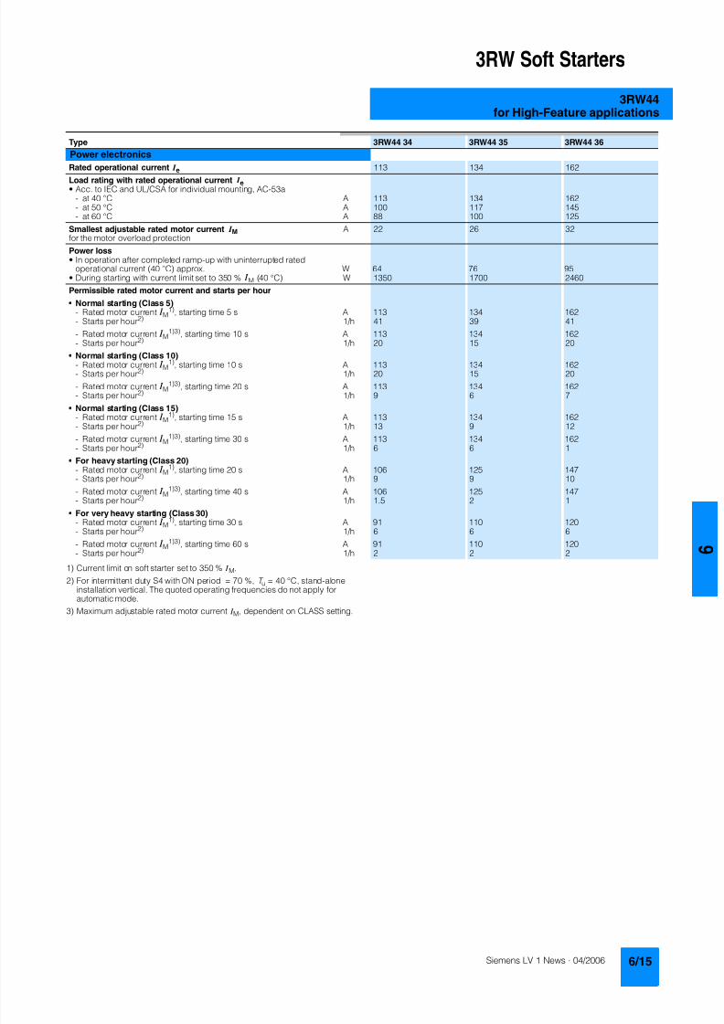
8122019 Arr Estado Solido
httpslidepdfcomreaderfullarr-estado-solido 1940
3RW Soft Starters
3RW44for High-Feature applications
1) Current limit on soft starter set to 350 I M
2) For intermittent duty S4 with ON period = 70 T u = 40 degC stand-aloneinstallation vertical The quoted operating frequencies do not apply forautomatic mode
3) Maximum adjustable rated motor current I M dependent on CLASS setting
Type 3RW44 34 3RW44 35 3RW44 36
Power electronics
Rated operational current I e 113 134 162
Load rating with rated operational current I ebull Acc to IEC and ULCSA for individual mounting AC-53a
- at 40 degC A 113 134 162- at 50 degC A 100 117 145- at 60 degC A 88 100 125
Smallest adjustable rated motor current I Mfor the motor overload protection
A 22 26 32
Power lossbull In operation after completed ramp-up with uninterrupted rated
operational current (40 degC) approx W 64 76 95bull During starting with current limit set to 350 I M (40 degC) W 1350 1700 2460
Permissible rated motor current and starts per hour
bull Normal starting (Class 5)- Rated motor current I M
1) starting time 5 s A 113 134 162- Starts per hour2) 1h 41 39 41
- Rated motor current I M1)3) starting time 10 s A 113 134 162
- Starts per hour2) 1h 20 15 20
bull Normal starting (Class 10)- Rated motor current I M
1) starting time 10 s A 113 134 162- Starts per hour2) 1h 20 15 20
- Rated motor current I M1)3) starting time 20 s A 113 134 162
- Starts per hour2) 1h 9 6 7
bull Normal starting (Class 15)- Rated motor current I M
1) starting time 15 s A 113 134 162- Starts per hour2) 1h 13 9 12
- Rated motor current I M1)3) starting time 30 s A 113 134 162
- Starts per hour2) 1h 6 6 1
bull For heavy starting (Class 20)- Rated motor current I M
1) starting time 20 s A 106 125 147- Starts per hour2) 1h 9 9 10
- Rated motor current I M1)3) starting time 40 s A 106 125 147
- Starts per hour2) 1h 15 2 1
bull For very heavy starting (Class 30)- Rated motor current I M
1) starting time 30 s A 91 110 120
- Starts per hour2) 1h 6 6 6- Rated motor current I M
1)3) starting time 60 s A 91 110 120- Starts per hour2) 1h 2 2 2
8122019 Arr Estado Solido
httpslidepdfcomreaderfullarr-estado-solido 2040
3RW Soft Starters
3RW44for High-Feature applications
1) Current limit on soft starter set to 350 I M
2) For intermittent duty S4 with ON period = 70 T u = 40 degC stand-aloneinstallation vertical The quoted operating frequencies do not apply forautomatic mode
3) Maximum adjustable rated motor current I M dependent on CLASS setting
Type 3RW44 43 3RW44 44 3RW44 45 3RW44 46 3RW44 47
Power electronics
Rated operational current I e 203 250 313 356 432
Load rating with rated operational current I ebull Acc to IEC and ULCSA for individual mounting AC-53a
- at 40 degC A 203 250 313 356 432- at 50 degC A 180 215 280 315 385- at 60 degC A 156 185 250 280 335
Smallest adjustable rated motor current I Mfor the motor overload protection
A 40 50 62 71 86
Power lossbull In operation after completed ramp-up with uninterrupted rated
operational current (40 degC) approx W 89 110 145 174 232bull During starting with current limit set to 350 I M (40 degC) W 3350 4000 4470 5350 5860
Permissible rated motor current and starts per hour
bull Normal starting (Class 5)- Rated motor current I M
1) starting time 5 s A 203 250 313 356 432- Starts per hour2) 1h 41 41 41 41 39
- Rated motor current I M1)3) starting time 10 s A 203 250 313 356 432
- Starts per hour2) 1h 20 20 19 17 16
bull Normal starting (Class 10)- Rated motor current I M
1) starting time 10 s A 203 250 313 356 432- Starts per hour2) 1h 20 20 19 17 16
- Rated motor current I M1)3) starting time 20 s A 203 250 313 356 432
- Starts per hour2) 1h 9 10 6 4 5
bull Normal starting (Class 15)- Rated motor current I M
1) starting time 15 s A 203 240 313 325 402- Starts per hour2) 1h 13 13 10 13 11
- Rated motor current I M1)3) starting time 30 s A 203 240 313 325 402
- Starts per hour2) 1h 3 6 1 2 1
bull For heavy starting (Class 20)- Rated motor current I M
1) starting time 20 s A 195 215 275 285 356- Starts per hour2) 1h 10 10 10 10 10
- Rated motor current I M1)3) starting time 40 s A 195 215 275 285 356
- Starts per hour2) 1h 1 5 1 3 1
bull For very heavy starting (Class 30)- Rated motor current I M
1) starting time 30 s A 162 180 220 240 285
- Starts per hour2) 1h 6 6 6 6 6- Rated motor current I M
1)3) starting time 60 s A 162 180 220 240 285- Starts per hour2) 1h 3 3 3 2 1
8122019 Arr Estado Solido
httpslidepdfcomreaderfullarr-estado-solido 2140
3RW Soft Starters
3RW44for High-Feature applications
1) Current limit on soft starter set to 350 I M
2) For intermittent duty S4 with ON period = 70 T u = 40 degC stand-aloneinstallation vertical The quoted operating frequencies do not apply forautomatic mode
3) Maximum adjustable rated motor current I M dependent on CLASS setting
Type 3RW44 53 3RW44 54 3RW44 55 3RW44 56 3RW44 57 3RW44 58
Power electronics
Rated operational current I e 551 615 693 780 880 970
Load rating with rated operational current I ebull Acc to IEC and ULCSA for individual mounting AC-53a
- at 40 degC A 551 615 693 780 880 970- at 50 degC A 494 551 615 693 780 850- at 60 degC A 438 489 551 615 693 760
Smallest adjustable rated motor current I Mfor the motor overload protection
A 110 123 138 156 176 194
Power lossbull In operation after completed ramp-up with uninterrupted rated
operational current (40 degC) approx W 159 186 220 214 250 270bull During starting with current limit set to 350 I M (40 degC) W 7020 8100 9500 11100 13100 15000
Permissible rated motor current and starts per hour
bull Normal starting (Class 5)- Rated motor current I M
1) starting time 5 s A 551 615 693 780 880 970- Starts per hour2) 1h 41 41 37 33 22 17
- Rated motor current I M1)3) starting time 10 s A 551 615 693 780 880 970
- Starts per hour2) 1h 20 20 16 13 8 5
bull Normal starting (Class 10)- Rated motor current I M
1) starting time 10 s A 551 615 693 780 880 970- Starts per hour2) 1h 20 20 16 13 8 5
- Rated motor current I M1)3) starting time 20 s A 551 615 693 780 880 970
- Starts per hour2) 1h 10 9 6 4 03 03
bull Normal starting (Class 15)- Rated motor current I M
1) starting time 15 s A 551 615 666 723 780 821- Starts per hour2) 1h 13 13 11 9 8 8
- Rated motor current I M1)3) starting time 30 s A 551 615 666 723 780 821
- Starts per hour2) 1h 6 4 3 1 04 05
bull For heavy starting (Class 20)- Rated motor current I M
1) starting time 20 s A 551 591 633 670 710 740- Starts per hour2) 1h 10 10 7 8 8 9
- Rated motor current I M1)3) starting time 40 s A 551 591 633 670 710 740
- Starts per hour2) 1h 4 2 1 1 04 1
bull For very heavy starting (Class 30)- Rated motor current I M
1) starting time 30 s A 500 525 551 575 600 630
- Starts per hour2) 1h 6 6 6 6 6 6- Rated motor current I M
1)3) starting time 60 s A 500 525 551 575 600 630- Starts per hour2) 1h 2 1 1 1 15 1
8122019 Arr Estado Solido
httpslidepdfcomreaderfullarr-estado-solido 2240
3RW Soft Starters
3RW44for High-Feature applications
1) When connecting cable lugs to DIN 46235 use 3RT19 56-4EA1 terminalcover for conductor cross-sections from 95 mmsup2 to ensure phase spacing
2) When connecting cable lugs to DIN 46234 the 3RT19 66-4EA1 terminalcover must be used for conductor cross-sections of 240 mmsup2 and more aswell as DIN 46235 for conductor cross-sections of 185 mmsup2 and more tokeep the phase clearance
Type 3RW44 2 3RW44 3 3RW44 4 3RW44 5
Conductor cross-sections
Screw
terminals
Main conductors
with box terminal 3RT19 55-4G (55 kW) 3RT19 66-4G
Front clampingpoint connected
bull Finely stranded with end sleeve mm2 16 70 70 240bull Finely stranded without end sleeve mm2 16 70 70 240bull Stranded mm2 16 70 95 300
bull Ribbon cable conductors(number x width x thickness)
mm min 3 x 9 x 08max 6 x 155 x 08
min 6 x 9 x 08max 20 x 24 x 05
bull AWG conductors solid or stranded AWG 6 20 30 600 kcmil
Rear clamping pointconnected
bull Finely stranded with end sleeve mm2 16 70 120 185bull Finely stranded without end sleeve mm2 16 70 120 185bull Stranded mm2 16 70 120 240
bull Ribbon cable conductors(number x width x thickness)
mm min 3 x 9 x 08max 6 x 155 x 08
min 6 x 9 x 08max 20 x 24 x 05
bull AWG conductors solid or stranded AWG 6 20 250 500 kcmil
Both clamping
points connected
bull Finely stranded with end sleeve mm2 max 1 x 50 1 x 70 min 2 x 50 max 2 x 185
bull Finely stranded without end sleeve mm2 max 1 x 50 1 x 70 min 2 x 50 max 2 x 185bull Stranded mm2 max 2 x 70 max 2 x 70 max 2 x 240
bull Ribbon cable conductors(number x width x thickness)
mm max 2 x (6 x 155 x 08) max 2 x (20 x 24 x 05)
bull AWG conductors solid or stranded AWG max 2 x 10 min 2 x 20max 2 x 500 kcmil
bull Terminal screws M10 (hexagon socket AF4) M12 (hexagon socket AF5)- Pickup torque 10 12 20 22
90 110 180 195
Screwterminals
Main conductors
with box terminal 3RT19 56-4G
Front or rear clamp-ing point connected
bull Finely stranded with end sleeve mm2 16 120bull Finely stranded without end sleeve mm2 16 120bull Stranded mm2 16 120
bull Ribbon cable conductors(number x width x thickness)
mm min 3 x 9 x 08max 6 x 155 x 08
bull AWG conductors solid or stranded AWG 6 250 kcmil
Both clampingpoints connected
bull Finely stranded with end sleeve mm2 max 1 x 95 1 x 120bull Finely stranded without end sleeve mm2 max 1 x 95 1 x 120bull Stranded mm2 max 2 x 120
bull Ribbon cable conductors(number x width x thickness)
mm max 2 x (10 x 155 x 08)
bull AWG conductors solid or stranded AWG max 2 x 30
Screwterminals
Main conductors
Without box terminalrail connection
bull Finely stranded with cable lug mm2 16 951) 50 2402) 50 2402)
bull Stranded with cable lug mm2 25 1201) 70 2402) 70 2402)
bull AWG conductors solid or stranded AWG 4 250 kcmil 20 500 kcmil 10 500 kcmil
bull Connecting bar (max width) mm 17 25 60
bull Terminal screws M8 x 25 (AF13) M10 x 30 (AF17) M12 x 40- Pickup torque NM 10 14 14 24 20 35lbin 89 124 124 210 177 310
8122019 Arr Estado Solido
httpslidepdfcomreaderfullarr-estado-solido 2340
3RW Soft Starters
3RW44for High-Feature applications
Soft starters Type 3RW44
Conductor cross-sections
Auxiliary conductors (1 or 2 conductors can be connected)
Screw terminals
bull Solid mm2 2 x 05 25bull Finely stranded with end sleeve mm2 2 x 05 15
bull AWG cables- Solid or stranded AWG 2 x 20 14- Finely stranded with end sleeve AWG 2 x 20 16
bull Terminal screws- Pickup torque NM 07 09
lbin 7 8
Spring-loaded terminals
bull Solid mm2 2 x 025 25bull Finely stranded with end sleeve mm2 2 x 025 15bull AWG conductors solid or stranded AWG 2 x 24 14
Standard Parameters
Electromagnetic compatibility acc to EN 60947-4-2
EMC interference immunityElectrostatic discharge (ESD) EN 61000-4-2 plusmn4 kV contact discharge plusmn8 kV air discharge
Electromagnetic RF fields EN 61000-4-3 Frequency range 80 1000 MHz with 80 at 1 kHzDegree of severity 3 10 Vm
Conducted RF interference EN 61000-4-6 Frequency range 150 kHz 80 MHz with 80 at 1 kHzInterference 10 V
RF voltages and RF currents on conductorsBurst EN 61000-4-4 plusmn2 kV5 kHzSurge EN 61000-4-5 plusmn1 kV line to line
plusmn2 kV line to ground
EMC interference emission
EMC interference field strength EN55011 Limit value of Class A at 30 1000 MHz
Radio interference voltage EN55011 Limit value of Class A at 015 30 MHz
Is an RI suppression filter necessary
Degree of noise suppression A (industrial applications) no
8122019 Arr Estado Solido
httpslidepdfcomreaderfullarr-estado-solido 2440
3RW Soft Starters
3RW44for High-Feature applications
Fuse assignment
The coordination type to which the motor feeder with soft starteris mounted depends on the application-specific requirements
Normally fuseless mounting (combination of motor starter pro-tector and soft starter) is sufficient If type 2 coordination is to befulfilled semiconductor fuses must be fitted in the motor feeder
1) The rated motor current must be considered when selecting the devices
2) The types of coordination are explained in more detail in theTechnical information LV 1 T under ndash Fuseless Load Feeders
Inline circuit fuseless version
Soft starters Motor starter protectorscircuit-breakers1)
Rated current 440 V +10 Rated currentG1 Q1Type A Type A
Type of coordination 12) 3RW44 22 3RW44 27 I q = 32 kA 3RW44 34 and 3RW44 35 I q = 16 kA 3RW44 36 3RW44 57 I q = 65 kA
3RW44 22 29 3RV10 42-4HA10 503RW44 23 36 3RV10 42-4JA10 633RW44 24 47 3RV10 42-4KA10 75
3RW44 25 57 3RV10 42-4LA10 903RW44 26 77 3RV10 42-4MA10 1003RW44 27 93 3RV10 42-4MA10 100
3RW44 34 113 3VL17 16-2DD36 1603RW44 35 134 3VL17 16-2DD36 1603RW44 36 162 3VL37 25-2DC36 250
3RW44 43 203 3VL47 31-3DC36 3153RW44 44 250 3VL47 31-3DC36 3153RW44 45 313 3VL47 40-3DC36 400
3RW44 46 356 3VL47 40-3DC36 4003RW44 47 432 3VL57 50-3DC36 500
3RW44 53 551 3VL67 80-3DE36 8003RW44 54 615 3VL67 80-3DE36 8003RW44 55 693 3VL67 80-3DE36 800
3RW44 56 780 3VL77 10-3AB36 10003RW44 57 880 3VL77 10-3AB36 10003RW44 58 970 3VL77 12-3AB36 1200
8122019 Arr Estado Solido
httpslidepdfcomreaderfullarr-estado-solido 2540
3RW Soft Starters
3RW44for High-Feature applications
1) If the ramp-down function Combined braking is selected no brakingcontactor is requiredIf the ramp-down function DC braking is selected a braking contactormust also be used (see table for type)For applications with large centrifugal masses (J Load gt J Motor) werecommend the function DC braking
2) Additional auxiliary relay K4LZXRT4A4T30(3RW44 soft starter with rated control supply voltage 230 V AC)LZXRT4A4S15(3RW44 soft starter with rated control supply voltage 115 V AC)
3) The types of coordination are explained in more detail in theTechnical information LV 1 T under ndash Fuseless Load Feeders
Inline circuit fused version (line protection only)
Soft starters Line protections Line contactorsup to 400 V
Braking contactors1)2)
Rated current 690 V +5 Rated current Size (optional) (for typical circuit see page 633)G1 F1 K1 K2 K3Type A Type A Type Type Type
Type of coordination 13) I q = 65 kA
3RW44 22 29 3NA3 820-6 50 00 3RT10 34 3RT15 26 --3RW44 23 36 3NA3 822-6 63 00 3RT10 35 3RT15 26 --
3RW44 24 47 3NA3 824-6 80 00 3RT10 36 3RT15 35 --3RW44 25 57 3NA3 830-6 100 00 3RT10 44 3RT15 35 --3RW44 26 77 3NA3 132-6 125 1 3RT10 45 3RT10 24 3RT10 353RW44 27 93 3NA3 136-6 160 1 3RT10 46 3RT10 25 3RT10 36
3RW44 34 113 3NA3 244-6 250 2 3RT10 54 3RT10 34 3RT10 443RW44 35 134 3NA3 244-6 250 2 3RT10 55 3RT10 36 3RT10 453RW44 36 162 3NA3 365-6 500 3 3RT10 56 3RT10 44 3RT10 45
3RW44 43 203 2 x 3NA3 354-6 2 x 355 3 3RT10 64 3RT10 44 3RT10 543RW44 44 250 2 x 3NA3 354-6 2 x 355 3 3RT10 65 3RT10 44 3RT10 553RW44 45 313 2 x 3NA3 365-6 2 x 500 3 3RT10 75 3RT10 54 3RT10 56
3RW44 46 356 2 x 3NA3 365-6 2 x 500 3 3RT10 75 3RT10 54 3RT10 563RW44 47 432 2 x 3NA3 365-6 2 x 500 3 3RT10 76 3RT10 55 3RT10 64
3RW44 53 551 2 x 3NA3 365-6 2 x 500 3 3TF68 44-0CM7 3TF68 44-0CM7 3TF68 44-0CM73RW44 54 615 2 x 3NA3 365-6 2 x 500 3 3TF68 44-0CM7 3TF68 44-0CM7 3TF68 44-0CM73RW44 55 693 2 x 3NA3 365-6 2 x 500 3 3TF69 44-0CM7 3TF69 44-0CM7 3TF69 44-0CM7
3RW44 56 780 2 x 3NA3 365-6 2 x 500 3 3TF69 44-0CM7 3TF69 44-0CM7 3TF69 44-0CM73RW44 57 880 2 x 3NA3 365-6 2 x 500 3 2 x 3TF69 44-0CM7 2 x 3TF69 44-0CM7 2 x 3TF69 44-0CM7
3RW44 58 970 3 x 3NA3 365-6 3 x 500 3
8122019 Arr Estado Solido
httpslidepdfcomreaderfullarr-estado-solido 2640
3RW Soft Starters
3RW44for High-Feature applications
1) If the ramp-down function Combined braking is selected no brakingcontactor is requiredIf the ramp-down function DC braking is selected a braking contactormust also be used (see table for type)For applications with large centrifugal masses (J Load gt J Motor) werecommend the function DC braking
2) Additional auxiliary relay K4LZXRT4A4T30(3RW44 soft starter with rated control supply voltage 230 V AC)LZXRT4A4S15(3RW44 soft starter with rated control supply voltage 115 V AC)
3) The types of coordination are explained in more detail in theTechnical information LV 1 T under ndash Fuseless Load Feeders
Inline circuit fused version with 3NE1 SITOR all-range fuse (semiconductor and line protection)
Soft starters All-range fuses Line contactors upto 400 V
Braking contactors1)2)
Ratedcurrent
Rated current Voltage Size (optional) (for typical circuit see page 633)
G1 Frsquo1 K1 K2 K3Type A Type A V Type Type Type
Type of coordination 23) I q = 65 kA
3RW44 22 29 3NE1 020-2 80 690 +5 00 3RT10 34 3RT15 26 --
3RW44 23 36 3NE1 020-2 80 690 +5 00 3RT10 35 3RT15 26 --3RW44 24 47 3NE1 021-2 100 690 +5 00 3RT10 36 3RT15 35 --
3RW44 25 57 3NE1 022-2 125 690 +5 00 3RT10 44 3RT15 35 --3RW44 26 77 3NE1 022-2 125 690 +5 00 3RT10 45 3RT10 24 3RT10 353RW44 27 93 3NE1 024-2 160 690 +5 1 3RT10 46 3RT10 25 3RT10 36
3RW44 34 113 3NE1 225-2 200 690 +5 1 3RT10 54 3RT10 34 3RT10 443RW44 35 134 3NE1 227-2 250 690 +5 1 3RT10 55 3RT10 36 3RT10 453RW44 36 162 3NE1 227-2 250 690 +5 1 3RT10 56 3RT10 44 3RT10 45
3RW44 43 203 3NE1 230-2 315 600 +10 1 3RT10 64 3RT10 44 3RT10 543RW44 44 250 3NE1 331-2 350 460 +10 2 3RT10 65 3RT10 44 3RT10 553RW44 45 313 3NE1 333-2 450 690 +5 2 3RT10 75 3RT10 54 3RT10 56
3RW44 46 356 3NE1 334-2 500 690 +5 2 3RT10 75 3RT10 54 3RT10 563RW44 47 432 3NE1 435-2 560 690 +5 3 3RT10 76 3RT10 55 3RT10 64
3RW44 53 551 2 x 3NE1 334-2 500 690 +10 2 3TF68 44-0CM7 3TF68 44-0CM7 3TF68 44-0CM73RW44 54 615 2 x 3NE1 334-2 500 690 +10 2 3TF68 44-0CM7 3TF68 44-0CM7 3TF68 44-0CM73RW44 55 693 2 x 3NE1 334-2 500 690 +10 2 3TF69 44-0CM7 3TF69 44-0CM7 3TF69 44-0CM7
3RW44 56 780 2 x 3NE1 435-2 560 690 +10 3 3TF69 44-0CM7 3TF69 44-0CM7 3TF69 44-0CM7
3RW44 57 880 2 x 3NE1 435-2 560 690 +10 3 2 x 3TF69 44-0CM7 2 x 3TF69 44-0CM7 2 x 3TF69 44-0CM73RW44 58 970 2 x 3NE1 435-2 560 690 +10 3
8122019 Arr Estado Solido
httpslidepdfcomreaderfullarr-estado-solido 2740
3RW Soft Starters
3RW44for High-Feature applications
1) If the ramp-down function Combined braking is selected no brakingcontactor is requiredIf the ramp-down function DC braking is selected a braking contactor
must also be used (see table for type)For applications with large centrifugal masses (J Load gt J Motor) werecommend the function DC braking
2) Additional auxiliary relay K4LZXRT4A4T30(3RW44 soft starter with rated control supply voltage 230 V AC)
LZXRT4A4S15(3RW44 soft starter with rated control supply voltage 115 V AC)
3) The types of coordination are explained in more detail in theTechnical information LV 1 T under ndash Fuseless Load Feeders
Inline circuit fused version with 3NE or 3NC SITOR semiconductor fuse(semiconductor protection by fuse lead and overload protection by circuit-breaker)
Soft starters Semiconductor fuses minimum Semiconductor fuses maximum Semiconductor fuses (cylinder)
Ratedcurrent
Rated current Size Rated current Size Rated current Size
G1 F3 F3 F3Type A Type A Type A Type A
Type of coordination 23) I q = 65 kA
3RW44 22 29 3NE4 120 80 0 3NE4 121 100 0 3NC2 280 80 22 x 58
3RW44 23 36 3NE4 121 100 0 3NE4 122 125 0 3NC2 200 100 22 x 583RW44 24 47 3NE4 121 100 0 3NE4 122 125 0 3NC2 200 100 22 x 58
3RW44 25 57 3NE4 122 125 0 3NE4 124 160 03RW44 26 77 3NE4 124 160 0 3NE4 124 160 03RW44 27 93 3NE3 224 160 1 3NE3 333 450 2
3RW44 34 113 3NE3 225 200 1 3NE3 335 560 23RW44 35 134 3NE3 225 200 1 3NE3 335 560 23RW44 36 162 3NE3 227 250 1 3NE3 333 450 2
3RW44 43 203 3NE3 230-0B 315 1 3NE3 333 450 23RW44 44 250 3NE3 230-0B 315 1 3NE3 333 450 23RW44 45 313 3NE3 233 450 1 3NE3 336 630 2
3RW44 46 356 3NE3 333 450 2 3NE3 336 630 23RW44 47 432 3NE3 335 560 2 3NE3 338-8 800 2
3RW44 53 551 2 x 3NE3 335 560 2 3 x 3NE3 334-0B 500 23RW44 54 615 2 x 3NE3 335 560 2 3 x 3NE3 334-0B 500 23RW44 55 693 2 x 3NE3 335 560 2 3 x 3NE3 334-0B 500 2
3RW44 56 780 2 x 3NE3 336 630 2 2 x 3NE3 340-8 900 2
3RW44 57 880 2 x 3NE3 336 630 2 2 x 3NE3 340-8 900 23RW44 58 970 2 x 3NE3 336 630 2 2 x 3NE3 340-8 900 2
Soft starters Line contactorsup to 400 V
Braking contactors1)2) Motor starter protectors circuit-breakers
Max line protection
Ratedcurrent
(optional) (for typical circuit see page 633) 440 V +10 Rated current 690 V +5 Rated current Size
G1 K1 Q1 F1Type A Type Type Type Type A Type A
Type of coordination 23) 3RW44 22 3RW44 27 I q = 32 kA 3RW44 34 and 3RW44 35 I q = 16 kA 3RW44 36 3RW44 57 I q = 65 kA
3RW44 22 29 3RT10 34 3RT15 26 -- 3RV10 41-4HA10 50 3NA3 820-6 50 003RW44 23 36 3RT10 35 3RT15 26 -- 3RV10 41-4JA10 63 3NA3 822-6 63 003RW44 24 47 3RT10 36 3RT15 35 -- 3RV10 41-4KA10 75 3NA3 824-6 80 00
3RW44 25 57 3RT10 44 3RT15 35 -- 3RV10 41-4LA10 90 3NA3 830-6 100 003RW44 26 77 3RT10 45 3RT10 24 3RT10 35 3RV10 41-4MA10 100 3NA3 132-6 125 13RW44 27 93 3RT10 46 3RT10 25 3RT10 36 3RV10 41-4MA10 100 3NA3 136-6 160 1
3RW44 34 113 3RT10 54 3RT10 34 3RT10 44 3VL17 16-1DD36 160 3NA3 244-6 250 2
3RW44 35 134 3RT10 55 3RT10 36 3RT10 45 3VL17 16-1DD36 160 3NA3 244-6 250 23RW44 36 162 3RT10 56 3RT10 44 3RT10 45 3VL37 25-1DC36 250 3NA3 365-6 500 3
3RW44 43 203 3RT10 64 3RT10 44 3RT10 54 3VL47 31-1DC36 315 2 x 3NA3 354-6 2 x 355 33RW44 44 250 3RT10 65 3RT10 44 3RT10 55 3VL47 31-1DC36 315 2 x 3NA3 354-6 2 x 355 33RW44 45 313 3RT10 75 3RT10 54 3RT10 56 3VL47 40-1DC36 400 2 x 3NA3 365-6 2 x 500 3
3RW44 46 356 3RT10 75 3RT10 54 3RT10 56 3VL47 40-1DC36 400 2 x 3NA3 365-6 2 x 500 33RW44 47 432 3RT10 76 3RT10 55 3RT10 64 3VL57 50-1DC36 500 2 x 3NA3 365-6 2 x 500 3
3RW44 53 551 3TF68 44-0CM7 3TF68 44-0CM7 3TF68 44-0CM7 3VL67 80-1AB36 800 2 x 3NA3 365-6 2 x 500 33RW44 54 615 3TF68 44-0CM7 3TF68 44-0CM7 3TF68 44-0CM7 3VL67 80-1AB36 800 2 x 3NA3 365-6 2 x 500 33RW44 55 693 3TF69 44-0CM7 3TF69 44-0CM7 3TF69 44-0CM7 3VL67 80-1AB36 800 2 x 3NA3 365-6 2 x 500 3
3RW44 56 780 3TF69 44-0CM7 3TF69 44-0CM7 3TF69 44-0CM7 3VL77 10-1AB36 1000 2 x 3NA3 365-6 2 x 500 33RW44 57 880 2 x
3TF69 44-0CM72 x3TF69 44-0CM7
2 x3TF69 44-0CM7
3VL77 10-1AB36 1000 2 x 3NA3 365-6 2 x 500 3
3RW44 58 970 3VL77 12-1AB36 1200 3 x 3NA3 365-6 3 x 500 3
8122019 Arr Estado Solido
httpslidepdfcomreaderfullarr-estado-solido 2840
3RW Soft Starters
3RW44for High-Feature applications
1) The types of coordination are explained in more detail in theTechnical information LV 1 T under ndash Fuseless Load FeedersThe type of coordination 2 only refers to soft starters not to feeder compo-nents ( I q = 65 kA)
Inside-delta circuit fused version with 3NE or 3NC SITOR fuses(semiconductor protection by fuse lead and overload protection by circuit-breaker)
Soft starters Semiconductor fuses minimum Semiconductor fuses maximum Semiconductor fuses (cylinder)
Ratedcurrent
Rated current Size Rated current Size Rated current Size
G1 F3 F3 F3Type A Type A Type A Type A
Type of coordination 21)
3RW44 22 50 3NE4 120 80 0 3NE4 121 100 0 3NC2 280 80 22 x 58
3RW44 23 62 3NE4 121 100 0 3NE4 122 125 0 3NC2 200 100 22 x 583RW44 24 81 3NE4 121 100 0 3NE4 122 125 0 3NC2 200 100 22 x 58
3RW44 25 99 3NE4 122 125 0 3NE4 124 160 03RW44 26 133 3NE4 124 160 0 3NE4 124 160 03RW44 27 161 3NE3 224 160 1 3NE3 333 450 2
3RW44 34 196 3NE3 225 200 1 3NE3 335 560 23RW44 35 232 3NE3 225 200 1 3NE3 335 560 23RW44 36 281 3NE3 227 250 1 3NE3 333 450 2
3RW44 43 352 3NE3 230-0B 315 1 3NE3 333 450 23RW44 44 433 3NE3 230-0B 315 1 3NE3 333 450 23RW44 45 542 3NE3 233 450 1 3NE3 336 630 2
3RW44 46 617 3NE3 333 450 2 3NE3 336 630 23RW44 47 748 3NE3 335 560 2 3NE3 338-8 800 2
3RW44 53 954 2 x 3NE3 335 560 2 3 x 3NE3 334-0B 500 23RW44 54 1065 2 x 3NE3 335 560 2 3 x 3NE3 334-0B 500 23RW44 55 1200 2 x 3NE3 335 560 2 3 x 3NE3 334-0B 500 2
3RW44 56 1351 2 x 3NE3 336 630 2 2 x 3NE3 340-8 900 2
3RW44 57 1524 2 x 3NE3 336 630 2 3 x 3NE3 340-8 900 23RW44 58 1680 2 x 3NE3 336 630 2 3 x 3NE3 340-8 900 2
Soft starters Line contactorsup to 400 V
Motor starter protectors cirduit-breakers
Line protections
Ratedcurrent
(optional) 440 V +10 Rated current 690 V +5 Rated current Size
G1 K1 Q1 F1Type A Type Type A Type A
Type of coordination 21)
3RW44 22 50 3RT10 36-1AP04 3RV10 4-4KA10 75 3NA3 824-6 80 003RW44 23 62 3RT10 44-1AP04 3RV10 4-4LA10 90 3NA3 830-6 100 003RW44 24 81 3RT10 46-1AP04 3RV10 4-4MA10 100 3NA3 132-6 125 1
3RW44 25 99 3RT10 54-1AP36 3VL27 16-DC36 160 3NA3 136-6 160 13RW44 26 133 3RT10 55-6AP36 3VL27 16-DC36 160 3NA3 240-6 200 23RW44 27 161 3RT10 56-6AP36 3VL37 20-DC36 200 3NA3 244-6 250 2
3RW44 34 196 3RT10 64-6AP36 3VL37 25-DC36 250 3NA3 360-6 400 3
3RW44 35 232 3RT10 65-6AP36 3VL47 31-DC36 315 3NA3 360-6 400 33RW44 36 281 3RT10 66-6AP36 3VL47 40-DC36 400 2 x 3NA3 360-6 2 x 400 3
3RW44 43 352 3RT10 75-6AP36 3VL47 40-DC36 400 2 x 3NA3 365-6 2 x 500 33RW44 44 433 3RT10 76-6AP36 3VL57 50-DC36 500 2 x 3NA3 365-6 2 x 500 33RW44 45 542 3TF68 44-0CM7 3VL57 63-DC36 800 3 x 3NA3 365-6 3 x 500 3
3RW44 46 617 3TF68 44-0CM7 3VL67 80-AB36 800 3 x 3NA3 365-6 3 x 500 33RW44 47 748 3TF69 3VL67 80-AB36 1000 3 x 3NA3 365-6 3 x 500 3
3RW44 53 954 2 x 3TF68 44-0CM7 3VL77 10-AB36 1000 3 x 3NA3 365-6 3 x 500 33RW44 54 1065 2 x 3TF68 44-0CM7 3VL77 12-AB36 1250 3 x 3NA3 365-6 3 x 500 33RW44 55 1200 2 x 3TF69 44-0CM7 3VL87 16-AB36 1600 3 x 3NA3 365-6 3 x 500 3
3RW44 56 1351 2 x 3TF69 44-0CM7 3VL87 16-AB36 1600 3 x 3NA3 372 3 x 630 33RW44 57 1524 2 x 3TF69 44-0CM7 3VL87 16-AB36 1600 3 x 3NA3 372 3 x 630 33RW44 58 1680 3WL12 20 2000 2 x 3NA3 480 2 x 1000 4
8122019 Arr Estado Solido
httpslidepdfcomreaderfullarr-estado-solido 2940
3RW Soft Starters
3RW44for High-Feature applications
Characteristic curves
Motor protection tripping characteristics for 3RW44(with symmetry)
Admissible mounting height
The admissible operational voltage is reduced to 460 V with a mountingheight of more than 2000 m
Motor protection characteristics for 3RW44(with phase unbalance)
e
2 4 6 101
Class 10 Class 15 Class 20
100
101
102
103
2
4
6
2
4
6
2
4
6
Class 5 Class 30
N S B 0
_ 0 1 5 0 0 a
[ s ]
x
T r i p p i n g t i m e
85
105
70
75
80
90
95
100
N S B 0
_ 0 1 7 0 4
0 1000 2000 3000 4000 5000 O p e r
a t i o n a
l r a
t e d c u r r e n
t I
i n
Mounting height in m
e
e
1001
Class 10 Class 15 Class 20
100
101
102
103
2
4
6
2
4
6
2
4
6
Class 5 Class 30
N S B 0
_ 0 1 7 0 6
[ s ]
x10
T r i p p
i n g
t i m e
8122019 Arr Estado Solido
httpslidepdfcomreaderfullarr-estado-solido 3040
3RW Soft Starters
3RW44for High-Feature applications
More information
Application examples for normal starting (Class 10)
Application examples for heavy starting (Class 20)
Application examples for very heavy starting (Class 30)
NoteThese tables present sample setting values and device sizesThey are intended only for the purposes of information and arenot binding The setting values depend on the application inquestion and must be optimized during commissioningThe soft starter dimensions should be checked where necessarywith the Win-Soft Starter software or with the help ofTechnical Assistance
Normal starting Class 10 (up to 20 s with 350 I n motor)The soft starter rating can be selected to be as high as the rating of the motor used
Application Conveyor belts Roller conveyors Compressors Small ventilators Pumps Hydraulic pumps
Starting parameters
bull Voltage ramp and currentlimiting- Starting voltage 70 60 50 30 30 30- Starting time s 10 10 10 10 10 10- Current limit value Deactivated Deactivated 4 x I M 4 x I M Deactivated Deactivated
bull Torque ramp- Starting torque 60 50 40 20 10 10- End torque 150 150 150 150 150 150- Starting time 10 10 10 10 10 10
bull Breakaway pulse Deactivated (0 ms) Deactivated (0 ms) Deactivated (0 ms) Deactivated (0 ms) Deactivated (0 ms) Deactivated (0 ms)
Ramp-down mode Smoothramp-down
Smoothramp-down
Free ramp-down Free ramp-down Pump ramp-down Free ramp-down
Heavy starting Class 20 (up to 40 s with 350 I n motor)The soft starter has to be selected one rating class higher than the motor used
Application Stirrers Centrifuges Milling machines
Starting parameters
bull Voltage ramp and currentlimiting- Starting voltage 30 30 30- Starting time s 30 30 30- Current limit value 4 x I M 4 x I M 4 x I M
bull Torque ramp- Starting torque 30 30 30- End torque 150 150 150- Starting time 30 30 30
bull Breakaway pulse Deactivated (0 ms) Deactivated (0 ms) Deactivated (0 ms)
Ramp-down mode Free ramp-down Free ramp-down Free ramp-down or DC braking
Very heavy starting Class 30 (up to 60 s with 350 I n motor)The soft starter has to be selected two rating classes higher than the motor used
Application Large ventilators Mills Breakers Circular sawbandsaws
Starting parameters
bull Voltage ramp and currentlimiting- Starting voltage 30 50 50 30- Starting time s 60 60 60 60- Current limit value 4 x I M 4 x I M 4 x I M 4 x I M
bull Torque ramp- Starting torque 20 50 50 20- End torque 150 150 150 150- Starting time 60 60 60 60
bull Breakaway pulse Deactivated (0 ms) 80 300 ms 80 300 ms Deactivated (0 ms)
Ramp-down mode Free ramp-down Free ramp-down Free ramp-down Free ramp-down
8122019 Arr Estado Solido
httpslidepdfcomreaderfullarr-estado-solido 3140
3RW Soft Starters
3RW44for High-Feature applications
Circuit concept
The SIRIUS 3RW44 soft starters can be operated in two differenttypes of circuit
bull Inline circuitThe controls for isolating and protecting the motor are simplyconnected in series with the soft starter The motor isconnected to the soft starter with three leads
bull Inside-delta circuitThe wiring is similar to that of wye-delta starters The phases ofthe soft starter are connected in series with the individual motorwindings The soft starter then only has to carry the phasecurrent amounting to about 58 of the rated motor current(conductor current)
Comparison of the types of circuit
Inline circuitRated current I e corresponds to the rated motor current I n3 leads to the motor
Inside-delta circuit
Rated current I e corresponds to approx 58 of the rated motorcurrent I n6 leads to the motor (as with wye-delta starters)
Which circuit
Using the inline circuit involves the lowest wiring complexityIf the soft starter to motor connections are long this contactsequence is preferableWith the inside-delta circuit there is double the wiring complexitybut a smaller size of device can be used at the same rating
Thanks to choosing the operational mode between the inline cir-cuit and inside-delta circuit the most favorable solution can al-ways be chosen
The braking function is possible only in the inline circuit
Configuration
The 3RW44 solid-state soft starters are designed for normalstarting In case of heavy starting or increased starting
frequency a larger device must be selectedFor long starting times it is recommended to have a PTC ther-mistor detector in the motor This also applies for the ramp-downmodes smooth ramp-down pump ramp-down and DC brakingbecause during the ramp-down time in these modes an addi-tional current loading applies in contrast to free ramp-down
In the motor feeder between the SIRIUS 3RW soft starter and themotor no capacitive elements are permitted (eg no reactive-power compensation equipment) In addition neither staticsystems for reactive-power compensation nor dynamic PFC(Power Factor Correction) must be operated in parallel duringstarting and ramp-down of the soft starter This is important toprevent faults arising on the compensation equipment andor thesoft starter
All elements of the main circuit (such as fuses and controls)
should be dimensioned for direct starting following the localshort-circuit conditions Fuses switching devices and overloadrelays must be ordered separately
The harmonic component load for starting currents must betaken into consideration for the selection of motor starterprotectors (selection of release)
NoteWhen switching on three-phase current motors voltage dropsnormally will occur with all types of starters (direct starters star- delta starters soft starters) On principle the feeding transformermust be configured such that when starting the motor thevoltage drop must occur within the admissible tolerance Whenthe feeding transformer is designed quite scarce the control vol- tage (being independent of the main voltage) should be sup- plied with a separate circuit in order to prevent the soft starterfrom switching off
Serial PC interface PROFIBUS DP communication moduleand parameterizing and operating software Soft Starter ES
The solid-state 3RW44 soft starters have a PC interface forcommunicating with the Soft Starter ES 2006 Smart software orto be connected to an external operating and monitoring mod-ule When using the optional communication module PROFIBUSthe 3RW44 soft starter can be connected to the PROFIBUS netand can communicate via GSD file or software Soft Starter ES2006 Professional
Manual for SIRIUS 3RW44
Besides containing all important information on planning com-missioning and servicing the manual also contains suggestedcircuits and the technical specifications for all devices
Win-Soft Starter selection and simulation program
With this software you can simulate and select all Siemens softstarters taking into account various parameters such as mainsproperties motor and load data and special applicationrequirements
The software is a valuable tool which makes complicatedlengthy manual calculations for determining the required softstarters superfluous
You can order the CD-ROM under the following order numberOrder No E20001-D1020-P302-V2-7400
More information can be found on the Internet athttpwwwsiemenscomsoftstarter
8122019 Arr Estado Solido
httpslidepdfcomreaderfullarr-estado-solido 3240
3RW Soft Starters
3RW44for High-Feature applications
SIRIUS soft starter training course (SD-SIRIUSO)
Siemens offers a 2-day training course on the SIRIUS solid-statesoft starters to keep customers and own personnel up-to-date on
configuring commissioning and servicing issuesPlease direct enquiries and applications to
AampD PT 4 (Trainings-Center Erlangen)Werner-von-Siemens-Str 65D-91052 ErlangenTelefon ++49 9131 729262Telefax ++49 9131 728172sibrainindustrysiemenscomhttp wwwsiemenscomsitrain
8122019 Arr Estado Solido
httpslidepdfcomreaderfullarr-estado-solido 3340
3RW Soft Starters
Project planning aids
Dimensional drawings
3RW44 2 3RW44 3 and 3RW44 4 for High-Feature applications
TypeDimension(mm)
a b c d e f g h I k l m n o p q
3RW44 2 180 170 37 11 167 100 240 270 180 148 75 153 7 184 66 M6 10 Nm
3RW44 3 180 170 37 17 167 100 240 270 180 148 75 153 7 198 9 M6 10 Nm
3RW44 4 210 210 48 25 190 140 269 298 205 166 16 166 9 230 11 M8 15 Nm
8122019 Arr Estado Solido
httpslidepdfcomreaderfullarr-estado-solido 3440
3RW Soft Starters
Project planning aids
3RW44 5 for High-Feature applications
147
173
195
118
N S B 0_
0 1 6 5 3
261
290
249
162
152
6 2 3
1 0 5
2 5 3
1 6 5
76
44
470
510
1
5 5
2
0Oslash14 40
6 3 8 5
5 9 0
8122019 Arr Estado Solido
httpslidepdfcomreaderfullarr-estado-solido 3540
3RW Soft Starters
Project planning aids
Schematics
1) Permissible values for main and control voltagesee Technical Specifications
3RW44 connection examples for main and control circuits
Main circuit Control circuitPossibility 1a Possibility 1Inline circuit with circuit-breaker and SITOR fuse(semiconductor protection only)
Control by pushbutton
Main circuit
Possibility 1b Possibility 1cInline circuit with full-rangeprotection (line andsemiconductor protection)
Inline circuit with line andSITOR fuse(semiconductor protection only)
Q1
L3L2L1
G1
F3
T1 T2 T3
M1
N S B 0_
0 1 4 9 0 a
L1 L2 L3
V1U1 W1
MPE 3~
3NPE 400 V AC 50 Hz
(optionalsemiconductorprotection fuse)
13 14 23 24 33 34 95 9896 +
T1 T2IN4IN3IN2IN1L-L+A1
A2
NPE
PE
G1
F2
NSB0_01494a
S t a r t
S 2
R e s e t S
3
StopS1
L1
On periodGrouperror
N o a c t i o n
N o a c t i o n
Noaction
PTC type Aor
Thermoclick
Noaction
1NPE 230 V AC 50 Hz
M o t o r o
n r i g h t
P S
1
1)
8122019 Arr Estado Solido
httpslidepdfcomreaderfullarr-estado-solido 3640
3RW Soft Starters
Project planning aids
1) Permissible values for main and control voltagesee Technical Specifications
2) Caution Risk of restartingThe start command (eg from the PLC) must be reset prior to a resetcommand because a new automatic restart will take place automaticallyif a start command is active after the reset command This appliesespecially in case of motor protection trippingFor safety reasons we recommend incorporating the group error output(terminals 95 and 96) in the controller
Main circuit Control circuit
Possibility 2 Possibility 2Inline circuit with main contactor Control of a main contactor and control by means of PLC
Q1
L3L2L1
G1
K1
F3
L1 L2 L3
T1 T2 T3
M1
N S B 0_
0 1 4 9 5 a
V1U1 W1
MPE 3~
1)
(optionalsemiconductorprotection)
(optional linecontactor if floatingswitching of themotor is planned)
3NPE 400 V AC 50 Hz
13 14 23 24 33 34 95 9896+
T1 T2IN4IN3IN2IN1L-L+A1
A2
NPE
PE
G1
K1NSB0_01496a
F2+24 V DC
M
L1 1NPE AC 230 V 50 Hz1)
Switch-on duration
M o t o r r i g h t
T r i p R e s e t
PLC outputs PLC inputs
N o a c t i o n
N o a c t i o n
No action No action
Group error
PTC type A Thermoclick
(optional line contactorif floating switchingof the motor is planned)
P S 1
ResetStart 2)
8122019 Arr Estado Solido
httpslidepdfcomreaderfullarr-estado-solido 3740
3RW Soft Starters
Project planning aids
1) Permissible values for main and control voltagesee Technical Specifications
2) Caution Risk of restartingThe start command (eg from the PLC) must be reset prior to a resetcommand because a new automatic restart will take place automaticallyif a start command is active after the reset command This applies espe-cially in case of motor protection trippingFor safety reasons we recommend incorporating the group error output(terminals 95 and 96) in the controller
3) If the ramp-down function Combined braking is selected no brakingcontactor is requiredIf the ramp-down function DC braking is selected a braking contactormust be used in addition Type see Fuse Coordination (inline circuit) onpages 621 to 623For applications with large centrifugal masses (J Load gt J Motor) werecommend the function DC brakingThe output 2 must be switched over to DC braking contactor
4) Auxiliary relay K4 egLZXRT4A4T30 (230 V AC rated control supply voltage)LZXRT4A4S15 (115 V AC rated control supply voltage)
Main circuit Control circuit
Possibility 3a Possibility 3aInline circuit with ramp-down function DC braking3)
(for device types 3RW44 22 to 3RW44 25)Control of the braking contactor3)
Main circuit Control circuit
Possibility 3b Possibility 3bInline circuit with ramp-down function DC braking3)
(for device types 3RW44 26 to 3RW44 47)Control of the braking contactor3)
Q1
L3L2
G1
F3
T1 T2 T3
M1
N S B 0_
0 1 5 0 1 a
L1 L2 L3
V1U1 W1
M
K2 K2 K2
PE 3~
1)
2
(optionalsemi-conductorprotection)
L1 3NPE 400 V AC 50 Hz
13 14 23 24 33 34 95 9896 +
T1 T2IN4IN3IN2IN1L-L+A1
A2
NPE
PEG1
K2NSB0_01502
R e s e t
M Start Reset
+24 V DC
K2
F2
1)
2)
No action Group error
N o a c t i o n
N o a c t i o n
On period
PLC output
PTC type Aor
Thermoclick
L1 1NPE 230 V AC 50 Hz
DC braking contactor 3)
K2 K33 3
G1
F3
T1 T2 T3
M1
N S B 0_
0 1
5 0 3 a
L1 L2 L3
V1U1 W1
MPE 3~
Q1
L3L2
1)
(optionalsemi-conductorprotection)
L1 3NPE 400 V AC 50 Hz
13 14 23 24 33 34 95 9896 +
T1 T2IN4IN3IN2IN1L-L+A1
A2
NPE
PE
G1
K4
NSB0_01504
R e s e t
K4 K4
K3 K2
K2 K3
+24 V DC
M Start Reset
F2
1)
2)
4)
PLC output
No action Group error
N o a c t i o n
N o a c t i o n
ON period
PTC type Aor
Thermoclick
M o t o r o n r i g h t
L1 1NPE 230 V AC 50 Hz
DC braking contactor 3)
8122019 Arr Estado Solido
httpslidepdfcomreaderfullarr-estado-solido 3840
3RW Soft Starters
Notes
1) Permissible values for main and control voltagesee Technical Specifications
2) Caution Risk of restartingThe start command (eg from the PLC) must be reset prior to a resetcommand because a new automatic restart will take place automaticallyif a start command is active after the reset command This appliesespecially in case of motor protection trippingFor safety reasons we recommend incorporating the group error output(terminals 95 and 96) in the controller
Main circuit Control circuit
Possibility 4a Possibility 4b Possibility 4Inside-delta circuit Change of direction of rotation for
inside-delta circuitControl by means of PLC
13 14 23 24 33 34 95 9896+
T1 T2IN4IN3IN2IN1L-L+A1
A2
NPE
PEG1
NSB0_01498a
+24 V DC
M
F2
L1 1NPE AC 230 V 50 Hz1)
2)
R e s e t
Switch-onduration
No action
Group error
N o a c t i o n
N o a c t i o n
No action
PTC type A orThermoclick
M o t o r r i g h t
PLC outputs PLC inputs
Start Reset
7
8122019 Arr Estado Solido
httpslidepdfcomreaderfullarr-estado-solido 3940
Appendix
Conditions of sale and delivery
Terms and Conditions of Sale and Delivery
By using this catalog you can acquire hardware and softwareproducts described therein from the Siemens AG subject to the
following terms Please note The scope the quality and the con-ditions for supplies and services including software productsby any Siemens entity having a registered office outside of Ger-many shall be subject exclusively to the General Terms andConditions of the respective Siemens entity
For customers with a seat or registered office in theFederal Republic of Germany
The bdquoGeneral Terms of Paymentldquo as well as the bdquoGeneral Condi-tions for the Supply of Products and Services of the Electricaland Electronics Industryldquo shall apply
For software products the bdquoGeneral License Conditions for Soft-ware Products for Automation and Drives for Customers with aSeat or registered Office in Germanyldquo shall apply
For customers with a seat or registered office outside of
Germany The bdquoGeneral Terms of Paymentldquo as well as the bdquoGeneral Condi-tions for Supplies of Siemens Automation and Drives for Cus-tomers with a Seat or registered Office outside of Germanyldquo shallapply
For software products the bdquoGeneral License Conditions for Soft-ware Products for Automation and Drives for Customers with aSeat or registered Office outside of Germanyldquo shall apply
General
The prices are in 991404 (Euro) ex works exclusive packaging
The sales tax (value added tax) is not included in the pricesIt shall be debited separately at the respective rate according tothe applicable legal regulations
In addition to the prices of products which include silver plump
aluminum andor copper surcharges may be calculated if therespective limits of the notes are exceeded The respective note(eg source German newspaper bdquoHandesblattldquo in categorybdquodeutsche Edelmetalleldquo and bdquoMetallverarbeiterldquo) for silver (bdquover-arbeitetes Silberldquo) plump (bdquoBlei in Kabelnldquo) aluminum (bdquoAlumin-ium in Kabelnldquo) and copper (bdquoElektrolytkupferldquo bdquoDEL-Notizldquo) re-spectively of the day the order or rather the on call order isreceived is decisive for the calculation of the surcharges
Surcharges of copper shall be calculated for Drives at a note(bdquoDEL-Notizldquo) above EUR 22500 100 Kg and for chokes trans-formers above EUR 15000 100 kg
Surcharges shall be charged based on the quantities of the ma-terials which are contained in the relevant products
Prices are subject to change without prior notice We will debitthe prices valid at the time of delivery
The dimensions are in mm In Germany according to the Ger-man law on units in measuring technology data in inches onlyapply to devices for export
Illustrations are not binding
Insofar as there are no remarks on the corresponding pages- especially with regard to data dimensions and weights given -these are subject to change without prior notice
Comprehensive Terms and Conditions of Sale and Delivery areavailable free of charge from your local Siemens business officeunder the following Order Nos
bull 6ZB5310-0KR30-0BA0(for customers based in the Federal Republic of Germany)
bull 6ZB5310-0KS53-0BA0(for customers based outside of theFederal Republic ofGermany)
or download them from the Internethttpwwwsiemenscomautomationmall (Germany AampD Mall Online-Help System)
Export regulations
The products listed in this catalog price list may be subject toEuropean German andor US export regulations
Therefore any export requiring a license is subject to approvalby the competent authorities
According to current provisions the following export regulations
must be observed with respect to the products featured in thiscatalog price list
Even without a label or with an ldquoAL Nldquo or ldquoECCN Nldquo authoriza-tion may be required due to the final destination and purpose forwhich the goods are to be used
The deciding factors are the AL or ECCN export authorizationindicated on order confirmations delivery notes and invoices
Errors excepted and subject to change without prior notice
AampDVuLEn 060306
AL Number of the German Export List
Products marked other than ldquoNldquo require an exportlicenseIn the case of software products the export des-ignations of the relevant data medium must alsobe generally adhered to
Goods labeled with an ldquoAL not equal to Nldquo aresubject to a European or German export authori-zation when being exported out of the EU
ECCN Export Control Classification Number
Products marked other than ldquoNldquo are subject to a
reexport license to specific countriesIn the case of software products the exportdesignations of the relevant data medium mustalso be generally adhered to
Goods labeled with an ldquoECCN not equal to Nldquo aresubject to a US re-export authorization
_ _ _ _
8122019 Arr Estado Solido
httpslidepdfcomreaderfullarr-estado-solido 4040
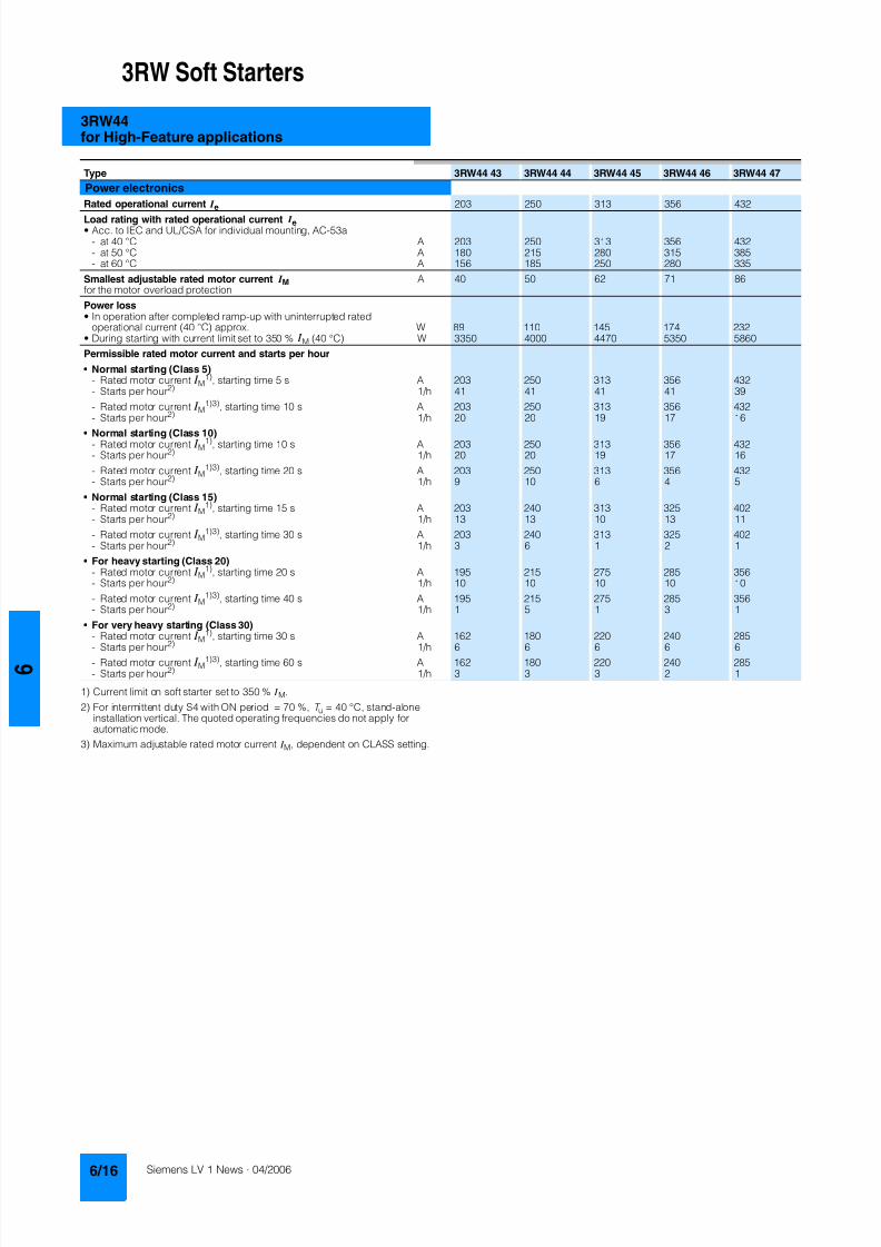
8122019 Arr Estado Solido
httpslidepdfcomreaderfullarr-estado-solido 2140
3RW Soft Starters
3RW44for High-Feature applications
1) Current limit on soft starter set to 350 I M
2) For intermittent duty S4 with ON period = 70 T u = 40 degC stand-aloneinstallation vertical The quoted operating frequencies do not apply forautomatic mode
3) Maximum adjustable rated motor current I M dependent on CLASS setting
Type 3RW44 53 3RW44 54 3RW44 55 3RW44 56 3RW44 57 3RW44 58
Power electronics
Rated operational current I e 551 615 693 780 880 970
Load rating with rated operational current I ebull Acc to IEC and ULCSA for individual mounting AC-53a
- at 40 degC A 551 615 693 780 880 970- at 50 degC A 494 551 615 693 780 850- at 60 degC A 438 489 551 615 693 760
Smallest adjustable rated motor current I Mfor the motor overload protection
A 110 123 138 156 176 194
Power lossbull In operation after completed ramp-up with uninterrupted rated
operational current (40 degC) approx W 159 186 220 214 250 270bull During starting with current limit set to 350 I M (40 degC) W 7020 8100 9500 11100 13100 15000
Permissible rated motor current and starts per hour
bull Normal starting (Class 5)- Rated motor current I M
1) starting time 5 s A 551 615 693 780 880 970- Starts per hour2) 1h 41 41 37 33 22 17
- Rated motor current I M1)3) starting time 10 s A 551 615 693 780 880 970
- Starts per hour2) 1h 20 20 16 13 8 5
bull Normal starting (Class 10)- Rated motor current I M
1) starting time 10 s A 551 615 693 780 880 970- Starts per hour2) 1h 20 20 16 13 8 5
- Rated motor current I M1)3) starting time 20 s A 551 615 693 780 880 970
- Starts per hour2) 1h 10 9 6 4 03 03
bull Normal starting (Class 15)- Rated motor current I M
1) starting time 15 s A 551 615 666 723 780 821- Starts per hour2) 1h 13 13 11 9 8 8
- Rated motor current I M1)3) starting time 30 s A 551 615 666 723 780 821
- Starts per hour2) 1h 6 4 3 1 04 05
bull For heavy starting (Class 20)- Rated motor current I M
1) starting time 20 s A 551 591 633 670 710 740- Starts per hour2) 1h 10 10 7 8 8 9
- Rated motor current I M1)3) starting time 40 s A 551 591 633 670 710 740
- Starts per hour2) 1h 4 2 1 1 04 1
bull For very heavy starting (Class 30)- Rated motor current I M
1) starting time 30 s A 500 525 551 575 600 630
- Starts per hour2) 1h 6 6 6 6 6 6- Rated motor current I M
1)3) starting time 60 s A 500 525 551 575 600 630- Starts per hour2) 1h 2 1 1 1 15 1
8122019 Arr Estado Solido
httpslidepdfcomreaderfullarr-estado-solido 2240
3RW Soft Starters
3RW44for High-Feature applications
1) When connecting cable lugs to DIN 46235 use 3RT19 56-4EA1 terminalcover for conductor cross-sections from 95 mmsup2 to ensure phase spacing
2) When connecting cable lugs to DIN 46234 the 3RT19 66-4EA1 terminalcover must be used for conductor cross-sections of 240 mmsup2 and more aswell as DIN 46235 for conductor cross-sections of 185 mmsup2 and more tokeep the phase clearance
Type 3RW44 2 3RW44 3 3RW44 4 3RW44 5
Conductor cross-sections
Screw
terminals
Main conductors
with box terminal 3RT19 55-4G (55 kW) 3RT19 66-4G
Front clampingpoint connected
bull Finely stranded with end sleeve mm2 16 70 70 240bull Finely stranded without end sleeve mm2 16 70 70 240bull Stranded mm2 16 70 95 300
bull Ribbon cable conductors(number x width x thickness)
mm min 3 x 9 x 08max 6 x 155 x 08
min 6 x 9 x 08max 20 x 24 x 05
bull AWG conductors solid or stranded AWG 6 20 30 600 kcmil
Rear clamping pointconnected
bull Finely stranded with end sleeve mm2 16 70 120 185bull Finely stranded without end sleeve mm2 16 70 120 185bull Stranded mm2 16 70 120 240
bull Ribbon cable conductors(number x width x thickness)
mm min 3 x 9 x 08max 6 x 155 x 08
min 6 x 9 x 08max 20 x 24 x 05
bull AWG conductors solid or stranded AWG 6 20 250 500 kcmil
Both clamping
points connected
bull Finely stranded with end sleeve mm2 max 1 x 50 1 x 70 min 2 x 50 max 2 x 185
bull Finely stranded without end sleeve mm2 max 1 x 50 1 x 70 min 2 x 50 max 2 x 185bull Stranded mm2 max 2 x 70 max 2 x 70 max 2 x 240
bull Ribbon cable conductors(number x width x thickness)
mm max 2 x (6 x 155 x 08) max 2 x (20 x 24 x 05)
bull AWG conductors solid or stranded AWG max 2 x 10 min 2 x 20max 2 x 500 kcmil
bull Terminal screws M10 (hexagon socket AF4) M12 (hexagon socket AF5)- Pickup torque 10 12 20 22
90 110 180 195
Screwterminals
Main conductors
with box terminal 3RT19 56-4G
Front or rear clamp-ing point connected
bull Finely stranded with end sleeve mm2 16 120bull Finely stranded without end sleeve mm2 16 120bull Stranded mm2 16 120
bull Ribbon cable conductors(number x width x thickness)
mm min 3 x 9 x 08max 6 x 155 x 08
bull AWG conductors solid or stranded AWG 6 250 kcmil
Both clampingpoints connected
bull Finely stranded with end sleeve mm2 max 1 x 95 1 x 120bull Finely stranded without end sleeve mm2 max 1 x 95 1 x 120bull Stranded mm2 max 2 x 120
bull Ribbon cable conductors(number x width x thickness)
mm max 2 x (10 x 155 x 08)
bull AWG conductors solid or stranded AWG max 2 x 30
Screwterminals
Main conductors
Without box terminalrail connection
bull Finely stranded with cable lug mm2 16 951) 50 2402) 50 2402)
bull Stranded with cable lug mm2 25 1201) 70 2402) 70 2402)
bull AWG conductors solid or stranded AWG 4 250 kcmil 20 500 kcmil 10 500 kcmil
bull Connecting bar (max width) mm 17 25 60
bull Terminal screws M8 x 25 (AF13) M10 x 30 (AF17) M12 x 40- Pickup torque NM 10 14 14 24 20 35lbin 89 124 124 210 177 310
8122019 Arr Estado Solido
httpslidepdfcomreaderfullarr-estado-solido 2340
3RW Soft Starters
3RW44for High-Feature applications
Soft starters Type 3RW44
Conductor cross-sections
Auxiliary conductors (1 or 2 conductors can be connected)
Screw terminals
bull Solid mm2 2 x 05 25bull Finely stranded with end sleeve mm2 2 x 05 15
bull AWG cables- Solid or stranded AWG 2 x 20 14- Finely stranded with end sleeve AWG 2 x 20 16
bull Terminal screws- Pickup torque NM 07 09
lbin 7 8
Spring-loaded terminals
bull Solid mm2 2 x 025 25bull Finely stranded with end sleeve mm2 2 x 025 15bull AWG conductors solid or stranded AWG 2 x 24 14
Standard Parameters
Electromagnetic compatibility acc to EN 60947-4-2
EMC interference immunityElectrostatic discharge (ESD) EN 61000-4-2 plusmn4 kV contact discharge plusmn8 kV air discharge
Electromagnetic RF fields EN 61000-4-3 Frequency range 80 1000 MHz with 80 at 1 kHzDegree of severity 3 10 Vm
Conducted RF interference EN 61000-4-6 Frequency range 150 kHz 80 MHz with 80 at 1 kHzInterference 10 V
RF voltages and RF currents on conductorsBurst EN 61000-4-4 plusmn2 kV5 kHzSurge EN 61000-4-5 plusmn1 kV line to line
plusmn2 kV line to ground
EMC interference emission
EMC interference field strength EN55011 Limit value of Class A at 30 1000 MHz
Radio interference voltage EN55011 Limit value of Class A at 015 30 MHz
Is an RI suppression filter necessary
Degree of noise suppression A (industrial applications) no
8122019 Arr Estado Solido
httpslidepdfcomreaderfullarr-estado-solido 2440
3RW Soft Starters
3RW44for High-Feature applications
Fuse assignment
The coordination type to which the motor feeder with soft starteris mounted depends on the application-specific requirements
Normally fuseless mounting (combination of motor starter pro-tector and soft starter) is sufficient If type 2 coordination is to befulfilled semiconductor fuses must be fitted in the motor feeder
1) The rated motor current must be considered when selecting the devices
2) The types of coordination are explained in more detail in theTechnical information LV 1 T under ndash Fuseless Load Feeders
Inline circuit fuseless version
Soft starters Motor starter protectorscircuit-breakers1)
Rated current 440 V +10 Rated currentG1 Q1Type A Type A
Type of coordination 12) 3RW44 22 3RW44 27 I q = 32 kA 3RW44 34 and 3RW44 35 I q = 16 kA 3RW44 36 3RW44 57 I q = 65 kA
3RW44 22 29 3RV10 42-4HA10 503RW44 23 36 3RV10 42-4JA10 633RW44 24 47 3RV10 42-4KA10 75
3RW44 25 57 3RV10 42-4LA10 903RW44 26 77 3RV10 42-4MA10 1003RW44 27 93 3RV10 42-4MA10 100
3RW44 34 113 3VL17 16-2DD36 1603RW44 35 134 3VL17 16-2DD36 1603RW44 36 162 3VL37 25-2DC36 250
3RW44 43 203 3VL47 31-3DC36 3153RW44 44 250 3VL47 31-3DC36 3153RW44 45 313 3VL47 40-3DC36 400
3RW44 46 356 3VL47 40-3DC36 4003RW44 47 432 3VL57 50-3DC36 500
3RW44 53 551 3VL67 80-3DE36 8003RW44 54 615 3VL67 80-3DE36 8003RW44 55 693 3VL67 80-3DE36 800
3RW44 56 780 3VL77 10-3AB36 10003RW44 57 880 3VL77 10-3AB36 10003RW44 58 970 3VL77 12-3AB36 1200
8122019 Arr Estado Solido
httpslidepdfcomreaderfullarr-estado-solido 2540
3RW Soft Starters
3RW44for High-Feature applications
1) If the ramp-down function Combined braking is selected no brakingcontactor is requiredIf the ramp-down function DC braking is selected a braking contactormust also be used (see table for type)For applications with large centrifugal masses (J Load gt J Motor) werecommend the function DC braking
2) Additional auxiliary relay K4LZXRT4A4T30(3RW44 soft starter with rated control supply voltage 230 V AC)LZXRT4A4S15(3RW44 soft starter with rated control supply voltage 115 V AC)
3) The types of coordination are explained in more detail in theTechnical information LV 1 T under ndash Fuseless Load Feeders
Inline circuit fused version (line protection only)
Soft starters Line protections Line contactorsup to 400 V
Braking contactors1)2)
Rated current 690 V +5 Rated current Size (optional) (for typical circuit see page 633)G1 F1 K1 K2 K3Type A Type A Type Type Type
Type of coordination 13) I q = 65 kA
3RW44 22 29 3NA3 820-6 50 00 3RT10 34 3RT15 26 --3RW44 23 36 3NA3 822-6 63 00 3RT10 35 3RT15 26 --
3RW44 24 47 3NA3 824-6 80 00 3RT10 36 3RT15 35 --3RW44 25 57 3NA3 830-6 100 00 3RT10 44 3RT15 35 --3RW44 26 77 3NA3 132-6 125 1 3RT10 45 3RT10 24 3RT10 353RW44 27 93 3NA3 136-6 160 1 3RT10 46 3RT10 25 3RT10 36
3RW44 34 113 3NA3 244-6 250 2 3RT10 54 3RT10 34 3RT10 443RW44 35 134 3NA3 244-6 250 2 3RT10 55 3RT10 36 3RT10 453RW44 36 162 3NA3 365-6 500 3 3RT10 56 3RT10 44 3RT10 45
3RW44 43 203 2 x 3NA3 354-6 2 x 355 3 3RT10 64 3RT10 44 3RT10 543RW44 44 250 2 x 3NA3 354-6 2 x 355 3 3RT10 65 3RT10 44 3RT10 553RW44 45 313 2 x 3NA3 365-6 2 x 500 3 3RT10 75 3RT10 54 3RT10 56
3RW44 46 356 2 x 3NA3 365-6 2 x 500 3 3RT10 75 3RT10 54 3RT10 563RW44 47 432 2 x 3NA3 365-6 2 x 500 3 3RT10 76 3RT10 55 3RT10 64
3RW44 53 551 2 x 3NA3 365-6 2 x 500 3 3TF68 44-0CM7 3TF68 44-0CM7 3TF68 44-0CM73RW44 54 615 2 x 3NA3 365-6 2 x 500 3 3TF68 44-0CM7 3TF68 44-0CM7 3TF68 44-0CM73RW44 55 693 2 x 3NA3 365-6 2 x 500 3 3TF69 44-0CM7 3TF69 44-0CM7 3TF69 44-0CM7
3RW44 56 780 2 x 3NA3 365-6 2 x 500 3 3TF69 44-0CM7 3TF69 44-0CM7 3TF69 44-0CM73RW44 57 880 2 x 3NA3 365-6 2 x 500 3 2 x 3TF69 44-0CM7 2 x 3TF69 44-0CM7 2 x 3TF69 44-0CM7
3RW44 58 970 3 x 3NA3 365-6 3 x 500 3
8122019 Arr Estado Solido
httpslidepdfcomreaderfullarr-estado-solido 2640
3RW Soft Starters
3RW44for High-Feature applications
1) If the ramp-down function Combined braking is selected no brakingcontactor is requiredIf the ramp-down function DC braking is selected a braking contactormust also be used (see table for type)For applications with large centrifugal masses (J Load gt J Motor) werecommend the function DC braking
2) Additional auxiliary relay K4LZXRT4A4T30(3RW44 soft starter with rated control supply voltage 230 V AC)LZXRT4A4S15(3RW44 soft starter with rated control supply voltage 115 V AC)
3) The types of coordination are explained in more detail in theTechnical information LV 1 T under ndash Fuseless Load Feeders
Inline circuit fused version with 3NE1 SITOR all-range fuse (semiconductor and line protection)
Soft starters All-range fuses Line contactors upto 400 V
Braking contactors1)2)
Ratedcurrent
Rated current Voltage Size (optional) (for typical circuit see page 633)
G1 Frsquo1 K1 K2 K3Type A Type A V Type Type Type
Type of coordination 23) I q = 65 kA
3RW44 22 29 3NE1 020-2 80 690 +5 00 3RT10 34 3RT15 26 --
3RW44 23 36 3NE1 020-2 80 690 +5 00 3RT10 35 3RT15 26 --3RW44 24 47 3NE1 021-2 100 690 +5 00 3RT10 36 3RT15 35 --
3RW44 25 57 3NE1 022-2 125 690 +5 00 3RT10 44 3RT15 35 --3RW44 26 77 3NE1 022-2 125 690 +5 00 3RT10 45 3RT10 24 3RT10 353RW44 27 93 3NE1 024-2 160 690 +5 1 3RT10 46 3RT10 25 3RT10 36
3RW44 34 113 3NE1 225-2 200 690 +5 1 3RT10 54 3RT10 34 3RT10 443RW44 35 134 3NE1 227-2 250 690 +5 1 3RT10 55 3RT10 36 3RT10 453RW44 36 162 3NE1 227-2 250 690 +5 1 3RT10 56 3RT10 44 3RT10 45
3RW44 43 203 3NE1 230-2 315 600 +10 1 3RT10 64 3RT10 44 3RT10 543RW44 44 250 3NE1 331-2 350 460 +10 2 3RT10 65 3RT10 44 3RT10 553RW44 45 313 3NE1 333-2 450 690 +5 2 3RT10 75 3RT10 54 3RT10 56
3RW44 46 356 3NE1 334-2 500 690 +5 2 3RT10 75 3RT10 54 3RT10 563RW44 47 432 3NE1 435-2 560 690 +5 3 3RT10 76 3RT10 55 3RT10 64
3RW44 53 551 2 x 3NE1 334-2 500 690 +10 2 3TF68 44-0CM7 3TF68 44-0CM7 3TF68 44-0CM73RW44 54 615 2 x 3NE1 334-2 500 690 +10 2 3TF68 44-0CM7 3TF68 44-0CM7 3TF68 44-0CM73RW44 55 693 2 x 3NE1 334-2 500 690 +10 2 3TF69 44-0CM7 3TF69 44-0CM7 3TF69 44-0CM7
3RW44 56 780 2 x 3NE1 435-2 560 690 +10 3 3TF69 44-0CM7 3TF69 44-0CM7 3TF69 44-0CM7
3RW44 57 880 2 x 3NE1 435-2 560 690 +10 3 2 x 3TF69 44-0CM7 2 x 3TF69 44-0CM7 2 x 3TF69 44-0CM73RW44 58 970 2 x 3NE1 435-2 560 690 +10 3
8122019 Arr Estado Solido
httpslidepdfcomreaderfullarr-estado-solido 2740
3RW Soft Starters
3RW44for High-Feature applications
1) If the ramp-down function Combined braking is selected no brakingcontactor is requiredIf the ramp-down function DC braking is selected a braking contactor
must also be used (see table for type)For applications with large centrifugal masses (J Load gt J Motor) werecommend the function DC braking
2) Additional auxiliary relay K4LZXRT4A4T30(3RW44 soft starter with rated control supply voltage 230 V AC)
LZXRT4A4S15(3RW44 soft starter with rated control supply voltage 115 V AC)
3) The types of coordination are explained in more detail in theTechnical information LV 1 T under ndash Fuseless Load Feeders
Inline circuit fused version with 3NE or 3NC SITOR semiconductor fuse(semiconductor protection by fuse lead and overload protection by circuit-breaker)
Soft starters Semiconductor fuses minimum Semiconductor fuses maximum Semiconductor fuses (cylinder)
Ratedcurrent
Rated current Size Rated current Size Rated current Size
G1 F3 F3 F3Type A Type A Type A Type A
Type of coordination 23) I q = 65 kA
3RW44 22 29 3NE4 120 80 0 3NE4 121 100 0 3NC2 280 80 22 x 58
3RW44 23 36 3NE4 121 100 0 3NE4 122 125 0 3NC2 200 100 22 x 583RW44 24 47 3NE4 121 100 0 3NE4 122 125 0 3NC2 200 100 22 x 58
3RW44 25 57 3NE4 122 125 0 3NE4 124 160 03RW44 26 77 3NE4 124 160 0 3NE4 124 160 03RW44 27 93 3NE3 224 160 1 3NE3 333 450 2
3RW44 34 113 3NE3 225 200 1 3NE3 335 560 23RW44 35 134 3NE3 225 200 1 3NE3 335 560 23RW44 36 162 3NE3 227 250 1 3NE3 333 450 2
3RW44 43 203 3NE3 230-0B 315 1 3NE3 333 450 23RW44 44 250 3NE3 230-0B 315 1 3NE3 333 450 23RW44 45 313 3NE3 233 450 1 3NE3 336 630 2
3RW44 46 356 3NE3 333 450 2 3NE3 336 630 23RW44 47 432 3NE3 335 560 2 3NE3 338-8 800 2
3RW44 53 551 2 x 3NE3 335 560 2 3 x 3NE3 334-0B 500 23RW44 54 615 2 x 3NE3 335 560 2 3 x 3NE3 334-0B 500 23RW44 55 693 2 x 3NE3 335 560 2 3 x 3NE3 334-0B 500 2
3RW44 56 780 2 x 3NE3 336 630 2 2 x 3NE3 340-8 900 2
3RW44 57 880 2 x 3NE3 336 630 2 2 x 3NE3 340-8 900 23RW44 58 970 2 x 3NE3 336 630 2 2 x 3NE3 340-8 900 2
Soft starters Line contactorsup to 400 V
Braking contactors1)2) Motor starter protectors circuit-breakers
Max line protection
Ratedcurrent
(optional) (for typical circuit see page 633) 440 V +10 Rated current 690 V +5 Rated current Size
G1 K1 Q1 F1Type A Type Type Type Type A Type A
Type of coordination 23) 3RW44 22 3RW44 27 I q = 32 kA 3RW44 34 and 3RW44 35 I q = 16 kA 3RW44 36 3RW44 57 I q = 65 kA
3RW44 22 29 3RT10 34 3RT15 26 -- 3RV10 41-4HA10 50 3NA3 820-6 50 003RW44 23 36 3RT10 35 3RT15 26 -- 3RV10 41-4JA10 63 3NA3 822-6 63 003RW44 24 47 3RT10 36 3RT15 35 -- 3RV10 41-4KA10 75 3NA3 824-6 80 00
3RW44 25 57 3RT10 44 3RT15 35 -- 3RV10 41-4LA10 90 3NA3 830-6 100 003RW44 26 77 3RT10 45 3RT10 24 3RT10 35 3RV10 41-4MA10 100 3NA3 132-6 125 13RW44 27 93 3RT10 46 3RT10 25 3RT10 36 3RV10 41-4MA10 100 3NA3 136-6 160 1
3RW44 34 113 3RT10 54 3RT10 34 3RT10 44 3VL17 16-1DD36 160 3NA3 244-6 250 2
3RW44 35 134 3RT10 55 3RT10 36 3RT10 45 3VL17 16-1DD36 160 3NA3 244-6 250 23RW44 36 162 3RT10 56 3RT10 44 3RT10 45 3VL37 25-1DC36 250 3NA3 365-6 500 3
3RW44 43 203 3RT10 64 3RT10 44 3RT10 54 3VL47 31-1DC36 315 2 x 3NA3 354-6 2 x 355 33RW44 44 250 3RT10 65 3RT10 44 3RT10 55 3VL47 31-1DC36 315 2 x 3NA3 354-6 2 x 355 33RW44 45 313 3RT10 75 3RT10 54 3RT10 56 3VL47 40-1DC36 400 2 x 3NA3 365-6 2 x 500 3
3RW44 46 356 3RT10 75 3RT10 54 3RT10 56 3VL47 40-1DC36 400 2 x 3NA3 365-6 2 x 500 33RW44 47 432 3RT10 76 3RT10 55 3RT10 64 3VL57 50-1DC36 500 2 x 3NA3 365-6 2 x 500 3
3RW44 53 551 3TF68 44-0CM7 3TF68 44-0CM7 3TF68 44-0CM7 3VL67 80-1AB36 800 2 x 3NA3 365-6 2 x 500 33RW44 54 615 3TF68 44-0CM7 3TF68 44-0CM7 3TF68 44-0CM7 3VL67 80-1AB36 800 2 x 3NA3 365-6 2 x 500 33RW44 55 693 3TF69 44-0CM7 3TF69 44-0CM7 3TF69 44-0CM7 3VL67 80-1AB36 800 2 x 3NA3 365-6 2 x 500 3
3RW44 56 780 3TF69 44-0CM7 3TF69 44-0CM7 3TF69 44-0CM7 3VL77 10-1AB36 1000 2 x 3NA3 365-6 2 x 500 33RW44 57 880 2 x
3TF69 44-0CM72 x3TF69 44-0CM7
2 x3TF69 44-0CM7
3VL77 10-1AB36 1000 2 x 3NA3 365-6 2 x 500 3
3RW44 58 970 3VL77 12-1AB36 1200 3 x 3NA3 365-6 3 x 500 3
8122019 Arr Estado Solido
httpslidepdfcomreaderfullarr-estado-solido 2840
3RW Soft Starters
3RW44for High-Feature applications
1) The types of coordination are explained in more detail in theTechnical information LV 1 T under ndash Fuseless Load FeedersThe type of coordination 2 only refers to soft starters not to feeder compo-nents ( I q = 65 kA)
Inside-delta circuit fused version with 3NE or 3NC SITOR fuses(semiconductor protection by fuse lead and overload protection by circuit-breaker)
Soft starters Semiconductor fuses minimum Semiconductor fuses maximum Semiconductor fuses (cylinder)
Ratedcurrent
Rated current Size Rated current Size Rated current Size
G1 F3 F3 F3Type A Type A Type A Type A
Type of coordination 21)
3RW44 22 50 3NE4 120 80 0 3NE4 121 100 0 3NC2 280 80 22 x 58
3RW44 23 62 3NE4 121 100 0 3NE4 122 125 0 3NC2 200 100 22 x 583RW44 24 81 3NE4 121 100 0 3NE4 122 125 0 3NC2 200 100 22 x 58
3RW44 25 99 3NE4 122 125 0 3NE4 124 160 03RW44 26 133 3NE4 124 160 0 3NE4 124 160 03RW44 27 161 3NE3 224 160 1 3NE3 333 450 2
3RW44 34 196 3NE3 225 200 1 3NE3 335 560 23RW44 35 232 3NE3 225 200 1 3NE3 335 560 23RW44 36 281 3NE3 227 250 1 3NE3 333 450 2
3RW44 43 352 3NE3 230-0B 315 1 3NE3 333 450 23RW44 44 433 3NE3 230-0B 315 1 3NE3 333 450 23RW44 45 542 3NE3 233 450 1 3NE3 336 630 2
3RW44 46 617 3NE3 333 450 2 3NE3 336 630 23RW44 47 748 3NE3 335 560 2 3NE3 338-8 800 2
3RW44 53 954 2 x 3NE3 335 560 2 3 x 3NE3 334-0B 500 23RW44 54 1065 2 x 3NE3 335 560 2 3 x 3NE3 334-0B 500 23RW44 55 1200 2 x 3NE3 335 560 2 3 x 3NE3 334-0B 500 2
3RW44 56 1351 2 x 3NE3 336 630 2 2 x 3NE3 340-8 900 2
3RW44 57 1524 2 x 3NE3 336 630 2 3 x 3NE3 340-8 900 23RW44 58 1680 2 x 3NE3 336 630 2 3 x 3NE3 340-8 900 2
Soft starters Line contactorsup to 400 V
Motor starter protectors cirduit-breakers
Line protections
Ratedcurrent
(optional) 440 V +10 Rated current 690 V +5 Rated current Size
G1 K1 Q1 F1Type A Type Type A Type A
Type of coordination 21)
3RW44 22 50 3RT10 36-1AP04 3RV10 4-4KA10 75 3NA3 824-6 80 003RW44 23 62 3RT10 44-1AP04 3RV10 4-4LA10 90 3NA3 830-6 100 003RW44 24 81 3RT10 46-1AP04 3RV10 4-4MA10 100 3NA3 132-6 125 1
3RW44 25 99 3RT10 54-1AP36 3VL27 16-DC36 160 3NA3 136-6 160 13RW44 26 133 3RT10 55-6AP36 3VL27 16-DC36 160 3NA3 240-6 200 23RW44 27 161 3RT10 56-6AP36 3VL37 20-DC36 200 3NA3 244-6 250 2
3RW44 34 196 3RT10 64-6AP36 3VL37 25-DC36 250 3NA3 360-6 400 3
3RW44 35 232 3RT10 65-6AP36 3VL47 31-DC36 315 3NA3 360-6 400 33RW44 36 281 3RT10 66-6AP36 3VL47 40-DC36 400 2 x 3NA3 360-6 2 x 400 3
3RW44 43 352 3RT10 75-6AP36 3VL47 40-DC36 400 2 x 3NA3 365-6 2 x 500 33RW44 44 433 3RT10 76-6AP36 3VL57 50-DC36 500 2 x 3NA3 365-6 2 x 500 33RW44 45 542 3TF68 44-0CM7 3VL57 63-DC36 800 3 x 3NA3 365-6 3 x 500 3
3RW44 46 617 3TF68 44-0CM7 3VL67 80-AB36 800 3 x 3NA3 365-6 3 x 500 33RW44 47 748 3TF69 3VL67 80-AB36 1000 3 x 3NA3 365-6 3 x 500 3
3RW44 53 954 2 x 3TF68 44-0CM7 3VL77 10-AB36 1000 3 x 3NA3 365-6 3 x 500 33RW44 54 1065 2 x 3TF68 44-0CM7 3VL77 12-AB36 1250 3 x 3NA3 365-6 3 x 500 33RW44 55 1200 2 x 3TF69 44-0CM7 3VL87 16-AB36 1600 3 x 3NA3 365-6 3 x 500 3
3RW44 56 1351 2 x 3TF69 44-0CM7 3VL87 16-AB36 1600 3 x 3NA3 372 3 x 630 33RW44 57 1524 2 x 3TF69 44-0CM7 3VL87 16-AB36 1600 3 x 3NA3 372 3 x 630 33RW44 58 1680 3WL12 20 2000 2 x 3NA3 480 2 x 1000 4
8122019 Arr Estado Solido
httpslidepdfcomreaderfullarr-estado-solido 2940
3RW Soft Starters
3RW44for High-Feature applications
Characteristic curves
Motor protection tripping characteristics for 3RW44(with symmetry)
Admissible mounting height
The admissible operational voltage is reduced to 460 V with a mountingheight of more than 2000 m
Motor protection characteristics for 3RW44(with phase unbalance)
e
2 4 6 101
Class 10 Class 15 Class 20
100
101
102
103
2
4
6
2
4
6
2
4
6
Class 5 Class 30
N S B 0
_ 0 1 5 0 0 a
[ s ]
x
T r i p p i n g t i m e
85
105
70
75
80
90
95
100
N S B 0
_ 0 1 7 0 4
0 1000 2000 3000 4000 5000 O p e r
a t i o n a
l r a
t e d c u r r e n
t I
i n
Mounting height in m
e
e
1001
Class 10 Class 15 Class 20
100
101
102
103
2
4
6
2
4
6
2
4
6
Class 5 Class 30
N S B 0
_ 0 1 7 0 6
[ s ]
x10
T r i p p
i n g
t i m e
8122019 Arr Estado Solido
httpslidepdfcomreaderfullarr-estado-solido 3040
3RW Soft Starters
3RW44for High-Feature applications
More information
Application examples for normal starting (Class 10)
Application examples for heavy starting (Class 20)
Application examples for very heavy starting (Class 30)
NoteThese tables present sample setting values and device sizesThey are intended only for the purposes of information and arenot binding The setting values depend on the application inquestion and must be optimized during commissioningThe soft starter dimensions should be checked where necessarywith the Win-Soft Starter software or with the help ofTechnical Assistance
Normal starting Class 10 (up to 20 s with 350 I n motor)The soft starter rating can be selected to be as high as the rating of the motor used
Application Conveyor belts Roller conveyors Compressors Small ventilators Pumps Hydraulic pumps
Starting parameters
bull Voltage ramp and currentlimiting- Starting voltage 70 60 50 30 30 30- Starting time s 10 10 10 10 10 10- Current limit value Deactivated Deactivated 4 x I M 4 x I M Deactivated Deactivated
bull Torque ramp- Starting torque 60 50 40 20 10 10- End torque 150 150 150 150 150 150- Starting time 10 10 10 10 10 10
bull Breakaway pulse Deactivated (0 ms) Deactivated (0 ms) Deactivated (0 ms) Deactivated (0 ms) Deactivated (0 ms) Deactivated (0 ms)
Ramp-down mode Smoothramp-down
Smoothramp-down
Free ramp-down Free ramp-down Pump ramp-down Free ramp-down
Heavy starting Class 20 (up to 40 s with 350 I n motor)The soft starter has to be selected one rating class higher than the motor used
Application Stirrers Centrifuges Milling machines
Starting parameters
bull Voltage ramp and currentlimiting- Starting voltage 30 30 30- Starting time s 30 30 30- Current limit value 4 x I M 4 x I M 4 x I M
bull Torque ramp- Starting torque 30 30 30- End torque 150 150 150- Starting time 30 30 30
bull Breakaway pulse Deactivated (0 ms) Deactivated (0 ms) Deactivated (0 ms)
Ramp-down mode Free ramp-down Free ramp-down Free ramp-down or DC braking
Very heavy starting Class 30 (up to 60 s with 350 I n motor)The soft starter has to be selected two rating classes higher than the motor used
Application Large ventilators Mills Breakers Circular sawbandsaws
Starting parameters
bull Voltage ramp and currentlimiting- Starting voltage 30 50 50 30- Starting time s 60 60 60 60- Current limit value 4 x I M 4 x I M 4 x I M 4 x I M
bull Torque ramp- Starting torque 20 50 50 20- End torque 150 150 150 150- Starting time 60 60 60 60
bull Breakaway pulse Deactivated (0 ms) 80 300 ms 80 300 ms Deactivated (0 ms)
Ramp-down mode Free ramp-down Free ramp-down Free ramp-down Free ramp-down
8122019 Arr Estado Solido
httpslidepdfcomreaderfullarr-estado-solido 3140
3RW Soft Starters
3RW44for High-Feature applications
Circuit concept
The SIRIUS 3RW44 soft starters can be operated in two differenttypes of circuit
bull Inline circuitThe controls for isolating and protecting the motor are simplyconnected in series with the soft starter The motor isconnected to the soft starter with three leads
bull Inside-delta circuitThe wiring is similar to that of wye-delta starters The phases ofthe soft starter are connected in series with the individual motorwindings The soft starter then only has to carry the phasecurrent amounting to about 58 of the rated motor current(conductor current)
Comparison of the types of circuit
Inline circuitRated current I e corresponds to the rated motor current I n3 leads to the motor
Inside-delta circuit
Rated current I e corresponds to approx 58 of the rated motorcurrent I n6 leads to the motor (as with wye-delta starters)
Which circuit
Using the inline circuit involves the lowest wiring complexityIf the soft starter to motor connections are long this contactsequence is preferableWith the inside-delta circuit there is double the wiring complexitybut a smaller size of device can be used at the same rating
Thanks to choosing the operational mode between the inline cir-cuit and inside-delta circuit the most favorable solution can al-ways be chosen
The braking function is possible only in the inline circuit
Configuration
The 3RW44 solid-state soft starters are designed for normalstarting In case of heavy starting or increased starting
frequency a larger device must be selectedFor long starting times it is recommended to have a PTC ther-mistor detector in the motor This also applies for the ramp-downmodes smooth ramp-down pump ramp-down and DC brakingbecause during the ramp-down time in these modes an addi-tional current loading applies in contrast to free ramp-down
In the motor feeder between the SIRIUS 3RW soft starter and themotor no capacitive elements are permitted (eg no reactive-power compensation equipment) In addition neither staticsystems for reactive-power compensation nor dynamic PFC(Power Factor Correction) must be operated in parallel duringstarting and ramp-down of the soft starter This is important toprevent faults arising on the compensation equipment andor thesoft starter
All elements of the main circuit (such as fuses and controls)
should be dimensioned for direct starting following the localshort-circuit conditions Fuses switching devices and overloadrelays must be ordered separately
The harmonic component load for starting currents must betaken into consideration for the selection of motor starterprotectors (selection of release)
NoteWhen switching on three-phase current motors voltage dropsnormally will occur with all types of starters (direct starters star- delta starters soft starters) On principle the feeding transformermust be configured such that when starting the motor thevoltage drop must occur within the admissible tolerance Whenthe feeding transformer is designed quite scarce the control vol- tage (being independent of the main voltage) should be sup- plied with a separate circuit in order to prevent the soft starterfrom switching off
Serial PC interface PROFIBUS DP communication moduleand parameterizing and operating software Soft Starter ES
The solid-state 3RW44 soft starters have a PC interface forcommunicating with the Soft Starter ES 2006 Smart software orto be connected to an external operating and monitoring mod-ule When using the optional communication module PROFIBUSthe 3RW44 soft starter can be connected to the PROFIBUS netand can communicate via GSD file or software Soft Starter ES2006 Professional
Manual for SIRIUS 3RW44
Besides containing all important information on planning com-missioning and servicing the manual also contains suggestedcircuits and the technical specifications for all devices
Win-Soft Starter selection and simulation program
With this software you can simulate and select all Siemens softstarters taking into account various parameters such as mainsproperties motor and load data and special applicationrequirements
The software is a valuable tool which makes complicatedlengthy manual calculations for determining the required softstarters superfluous
You can order the CD-ROM under the following order numberOrder No E20001-D1020-P302-V2-7400
More information can be found on the Internet athttpwwwsiemenscomsoftstarter
8122019 Arr Estado Solido
httpslidepdfcomreaderfullarr-estado-solido 3240
3RW Soft Starters
3RW44for High-Feature applications
SIRIUS soft starter training course (SD-SIRIUSO)
Siemens offers a 2-day training course on the SIRIUS solid-statesoft starters to keep customers and own personnel up-to-date on
configuring commissioning and servicing issuesPlease direct enquiries and applications to
AampD PT 4 (Trainings-Center Erlangen)Werner-von-Siemens-Str 65D-91052 ErlangenTelefon ++49 9131 729262Telefax ++49 9131 728172sibrainindustrysiemenscomhttp wwwsiemenscomsitrain
8122019 Arr Estado Solido
httpslidepdfcomreaderfullarr-estado-solido 3340
3RW Soft Starters
Project planning aids
Dimensional drawings
3RW44 2 3RW44 3 and 3RW44 4 for High-Feature applications
TypeDimension(mm)
a b c d e f g h I k l m n o p q
3RW44 2 180 170 37 11 167 100 240 270 180 148 75 153 7 184 66 M6 10 Nm
3RW44 3 180 170 37 17 167 100 240 270 180 148 75 153 7 198 9 M6 10 Nm
3RW44 4 210 210 48 25 190 140 269 298 205 166 16 166 9 230 11 M8 15 Nm
8122019 Arr Estado Solido
httpslidepdfcomreaderfullarr-estado-solido 3440
3RW Soft Starters
Project planning aids
3RW44 5 for High-Feature applications
147
173
195
118
N S B 0_
0 1 6 5 3
261
290
249
162
152
6 2 3
1 0 5
2 5 3
1 6 5
76
44
470
510
1
5 5
2
0Oslash14 40
6 3 8 5
5 9 0
8122019 Arr Estado Solido
httpslidepdfcomreaderfullarr-estado-solido 3540
3RW Soft Starters
Project planning aids
Schematics
1) Permissible values for main and control voltagesee Technical Specifications
3RW44 connection examples for main and control circuits
Main circuit Control circuitPossibility 1a Possibility 1Inline circuit with circuit-breaker and SITOR fuse(semiconductor protection only)
Control by pushbutton
Main circuit
Possibility 1b Possibility 1cInline circuit with full-rangeprotection (line andsemiconductor protection)
Inline circuit with line andSITOR fuse(semiconductor protection only)
Q1
L3L2L1
G1
F3
T1 T2 T3
M1
N S B 0_
0 1 4 9 0 a
L1 L2 L3
V1U1 W1
MPE 3~
3NPE 400 V AC 50 Hz
(optionalsemiconductorprotection fuse)
13 14 23 24 33 34 95 9896 +
T1 T2IN4IN3IN2IN1L-L+A1
A2
NPE
PE
G1
F2
NSB0_01494a
S t a r t
S 2
R e s e t S
3
StopS1
L1
On periodGrouperror
N o a c t i o n
N o a c t i o n
Noaction
PTC type Aor
Thermoclick
Noaction
1NPE 230 V AC 50 Hz
M o t o r o
n r i g h t
P S
1
1)
8122019 Arr Estado Solido
httpslidepdfcomreaderfullarr-estado-solido 3640
3RW Soft Starters
Project planning aids
1) Permissible values for main and control voltagesee Technical Specifications
2) Caution Risk of restartingThe start command (eg from the PLC) must be reset prior to a resetcommand because a new automatic restart will take place automaticallyif a start command is active after the reset command This appliesespecially in case of motor protection trippingFor safety reasons we recommend incorporating the group error output(terminals 95 and 96) in the controller
Main circuit Control circuit
Possibility 2 Possibility 2Inline circuit with main contactor Control of a main contactor and control by means of PLC
Q1
L3L2L1
G1
K1
F3
L1 L2 L3
T1 T2 T3
M1
N S B 0_
0 1 4 9 5 a
V1U1 W1
MPE 3~
1)
(optionalsemiconductorprotection)
(optional linecontactor if floatingswitching of themotor is planned)
3NPE 400 V AC 50 Hz
13 14 23 24 33 34 95 9896+
T1 T2IN4IN3IN2IN1L-L+A1
A2
NPE
PE
G1
K1NSB0_01496a
F2+24 V DC
M
L1 1NPE AC 230 V 50 Hz1)
Switch-on duration
M o t o r r i g h t
T r i p R e s e t
PLC outputs PLC inputs
N o a c t i o n
N o a c t i o n
No action No action
Group error
PTC type A Thermoclick
(optional line contactorif floating switchingof the motor is planned)
P S 1
ResetStart 2)
8122019 Arr Estado Solido
httpslidepdfcomreaderfullarr-estado-solido 3740
3RW Soft Starters
Project planning aids
1) Permissible values for main and control voltagesee Technical Specifications
2) Caution Risk of restartingThe start command (eg from the PLC) must be reset prior to a resetcommand because a new automatic restart will take place automaticallyif a start command is active after the reset command This applies espe-cially in case of motor protection trippingFor safety reasons we recommend incorporating the group error output(terminals 95 and 96) in the controller
3) If the ramp-down function Combined braking is selected no brakingcontactor is requiredIf the ramp-down function DC braking is selected a braking contactormust be used in addition Type see Fuse Coordination (inline circuit) onpages 621 to 623For applications with large centrifugal masses (J Load gt J Motor) werecommend the function DC brakingThe output 2 must be switched over to DC braking contactor
4) Auxiliary relay K4 egLZXRT4A4T30 (230 V AC rated control supply voltage)LZXRT4A4S15 (115 V AC rated control supply voltage)
Main circuit Control circuit
Possibility 3a Possibility 3aInline circuit with ramp-down function DC braking3)
(for device types 3RW44 22 to 3RW44 25)Control of the braking contactor3)
Main circuit Control circuit
Possibility 3b Possibility 3bInline circuit with ramp-down function DC braking3)
(for device types 3RW44 26 to 3RW44 47)Control of the braking contactor3)
Q1
L3L2
G1
F3
T1 T2 T3
M1
N S B 0_
0 1 5 0 1 a
L1 L2 L3
V1U1 W1
M
K2 K2 K2
PE 3~
1)
2
(optionalsemi-conductorprotection)
L1 3NPE 400 V AC 50 Hz
13 14 23 24 33 34 95 9896 +
T1 T2IN4IN3IN2IN1L-L+A1
A2
NPE
PEG1
K2NSB0_01502
R e s e t
M Start Reset
+24 V DC
K2
F2
1)
2)
No action Group error
N o a c t i o n
N o a c t i o n
On period
PLC output
PTC type Aor
Thermoclick
L1 1NPE 230 V AC 50 Hz
DC braking contactor 3)
K2 K33 3
G1
F3
T1 T2 T3
M1
N S B 0_
0 1
5 0 3 a
L1 L2 L3
V1U1 W1
MPE 3~
Q1
L3L2
1)
(optionalsemi-conductorprotection)
L1 3NPE 400 V AC 50 Hz
13 14 23 24 33 34 95 9896 +
T1 T2IN4IN3IN2IN1L-L+A1
A2
NPE
PE
G1
K4
NSB0_01504
R e s e t
K4 K4
K3 K2
K2 K3
+24 V DC
M Start Reset
F2
1)
2)
4)
PLC output
No action Group error
N o a c t i o n
N o a c t i o n
ON period
PTC type Aor
Thermoclick
M o t o r o n r i g h t
L1 1NPE 230 V AC 50 Hz
DC braking contactor 3)
8122019 Arr Estado Solido
httpslidepdfcomreaderfullarr-estado-solido 3840
3RW Soft Starters
Notes
1) Permissible values for main and control voltagesee Technical Specifications
2) Caution Risk of restartingThe start command (eg from the PLC) must be reset prior to a resetcommand because a new automatic restart will take place automaticallyif a start command is active after the reset command This appliesespecially in case of motor protection trippingFor safety reasons we recommend incorporating the group error output(terminals 95 and 96) in the controller
Main circuit Control circuit
Possibility 4a Possibility 4b Possibility 4Inside-delta circuit Change of direction of rotation for
inside-delta circuitControl by means of PLC
13 14 23 24 33 34 95 9896+
T1 T2IN4IN3IN2IN1L-L+A1
A2
NPE
PEG1
NSB0_01498a
+24 V DC
M
F2
L1 1NPE AC 230 V 50 Hz1)
2)
R e s e t
Switch-onduration
No action
Group error
N o a c t i o n
N o a c t i o n
No action
PTC type A orThermoclick
M o t o r r i g h t
PLC outputs PLC inputs
Start Reset
7
8122019 Arr Estado Solido
httpslidepdfcomreaderfullarr-estado-solido 3940
Appendix
Conditions of sale and delivery
Terms and Conditions of Sale and Delivery
By using this catalog you can acquire hardware and softwareproducts described therein from the Siemens AG subject to the
following terms Please note The scope the quality and the con-ditions for supplies and services including software productsby any Siemens entity having a registered office outside of Ger-many shall be subject exclusively to the General Terms andConditions of the respective Siemens entity
For customers with a seat or registered office in theFederal Republic of Germany
The bdquoGeneral Terms of Paymentldquo as well as the bdquoGeneral Condi-tions for the Supply of Products and Services of the Electricaland Electronics Industryldquo shall apply
For software products the bdquoGeneral License Conditions for Soft-ware Products for Automation and Drives for Customers with aSeat or registered Office in Germanyldquo shall apply
For customers with a seat or registered office outside of
Germany The bdquoGeneral Terms of Paymentldquo as well as the bdquoGeneral Condi-tions for Supplies of Siemens Automation and Drives for Cus-tomers with a Seat or registered Office outside of Germanyldquo shallapply
For software products the bdquoGeneral License Conditions for Soft-ware Products for Automation and Drives for Customers with aSeat or registered Office outside of Germanyldquo shall apply
General
The prices are in 991404 (Euro) ex works exclusive packaging
The sales tax (value added tax) is not included in the pricesIt shall be debited separately at the respective rate according tothe applicable legal regulations
In addition to the prices of products which include silver plump
aluminum andor copper surcharges may be calculated if therespective limits of the notes are exceeded The respective note(eg source German newspaper bdquoHandesblattldquo in categorybdquodeutsche Edelmetalleldquo and bdquoMetallverarbeiterldquo) for silver (bdquover-arbeitetes Silberldquo) plump (bdquoBlei in Kabelnldquo) aluminum (bdquoAlumin-ium in Kabelnldquo) and copper (bdquoElektrolytkupferldquo bdquoDEL-Notizldquo) re-spectively of the day the order or rather the on call order isreceived is decisive for the calculation of the surcharges
Surcharges of copper shall be calculated for Drives at a note(bdquoDEL-Notizldquo) above EUR 22500 100 Kg and for chokes trans-formers above EUR 15000 100 kg
Surcharges shall be charged based on the quantities of the ma-terials which are contained in the relevant products
Prices are subject to change without prior notice We will debitthe prices valid at the time of delivery
The dimensions are in mm In Germany according to the Ger-man law on units in measuring technology data in inches onlyapply to devices for export
Illustrations are not binding
Insofar as there are no remarks on the corresponding pages- especially with regard to data dimensions and weights given -these are subject to change without prior notice
Comprehensive Terms and Conditions of Sale and Delivery areavailable free of charge from your local Siemens business officeunder the following Order Nos
bull 6ZB5310-0KR30-0BA0(for customers based in the Federal Republic of Germany)
bull 6ZB5310-0KS53-0BA0(for customers based outside of theFederal Republic ofGermany)
or download them from the Internethttpwwwsiemenscomautomationmall (Germany AampD Mall Online-Help System)
Export regulations
The products listed in this catalog price list may be subject toEuropean German andor US export regulations
Therefore any export requiring a license is subject to approvalby the competent authorities
According to current provisions the following export regulations
must be observed with respect to the products featured in thiscatalog price list
Even without a label or with an ldquoAL Nldquo or ldquoECCN Nldquo authoriza-tion may be required due to the final destination and purpose forwhich the goods are to be used
The deciding factors are the AL or ECCN export authorizationindicated on order confirmations delivery notes and invoices
Errors excepted and subject to change without prior notice
AampDVuLEn 060306
AL Number of the German Export List
Products marked other than ldquoNldquo require an exportlicenseIn the case of software products the export des-ignations of the relevant data medium must alsobe generally adhered to
Goods labeled with an ldquoAL not equal to Nldquo aresubject to a European or German export authori-zation when being exported out of the EU
ECCN Export Control Classification Number
Products marked other than ldquoNldquo are subject to a
reexport license to specific countriesIn the case of software products the exportdesignations of the relevant data medium mustalso be generally adhered to
Goods labeled with an ldquoECCN not equal to Nldquo aresubject to a US re-export authorization
_ _ _ _
8122019 Arr Estado Solido
httpslidepdfcomreaderfullarr-estado-solido 4040
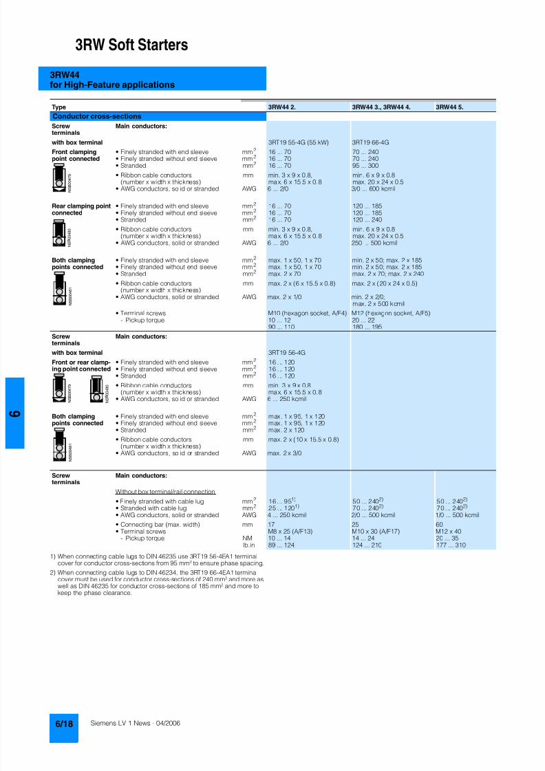
8122019 Arr Estado Solido
httpslidepdfcomreaderfullarr-estado-solido 2240
3RW Soft Starters
3RW44for High-Feature applications
1) When connecting cable lugs to DIN 46235 use 3RT19 56-4EA1 terminalcover for conductor cross-sections from 95 mmsup2 to ensure phase spacing
2) When connecting cable lugs to DIN 46234 the 3RT19 66-4EA1 terminalcover must be used for conductor cross-sections of 240 mmsup2 and more aswell as DIN 46235 for conductor cross-sections of 185 mmsup2 and more tokeep the phase clearance
Type 3RW44 2 3RW44 3 3RW44 4 3RW44 5
Conductor cross-sections
Screw
terminals
Main conductors
with box terminal 3RT19 55-4G (55 kW) 3RT19 66-4G
Front clampingpoint connected
bull Finely stranded with end sleeve mm2 16 70 70 240bull Finely stranded without end sleeve mm2 16 70 70 240bull Stranded mm2 16 70 95 300
bull Ribbon cable conductors(number x width x thickness)
mm min 3 x 9 x 08max 6 x 155 x 08
min 6 x 9 x 08max 20 x 24 x 05
bull AWG conductors solid or stranded AWG 6 20 30 600 kcmil
Rear clamping pointconnected
bull Finely stranded with end sleeve mm2 16 70 120 185bull Finely stranded without end sleeve mm2 16 70 120 185bull Stranded mm2 16 70 120 240
bull Ribbon cable conductors(number x width x thickness)
mm min 3 x 9 x 08max 6 x 155 x 08
min 6 x 9 x 08max 20 x 24 x 05
bull AWG conductors solid or stranded AWG 6 20 250 500 kcmil
Both clamping
points connected
bull Finely stranded with end sleeve mm2 max 1 x 50 1 x 70 min 2 x 50 max 2 x 185
bull Finely stranded without end sleeve mm2 max 1 x 50 1 x 70 min 2 x 50 max 2 x 185bull Stranded mm2 max 2 x 70 max 2 x 70 max 2 x 240
bull Ribbon cable conductors(number x width x thickness)
mm max 2 x (6 x 155 x 08) max 2 x (20 x 24 x 05)
bull AWG conductors solid or stranded AWG max 2 x 10 min 2 x 20max 2 x 500 kcmil
bull Terminal screws M10 (hexagon socket AF4) M12 (hexagon socket AF5)- Pickup torque 10 12 20 22
90 110 180 195
Screwterminals
Main conductors
with box terminal 3RT19 56-4G
Front or rear clamp-ing point connected
bull Finely stranded with end sleeve mm2 16 120bull Finely stranded without end sleeve mm2 16 120bull Stranded mm2 16 120
bull Ribbon cable conductors(number x width x thickness)
mm min 3 x 9 x 08max 6 x 155 x 08
bull AWG conductors solid or stranded AWG 6 250 kcmil
Both clampingpoints connected
bull Finely stranded with end sleeve mm2 max 1 x 95 1 x 120bull Finely stranded without end sleeve mm2 max 1 x 95 1 x 120bull Stranded mm2 max 2 x 120
bull Ribbon cable conductors(number x width x thickness)
mm max 2 x (10 x 155 x 08)
bull AWG conductors solid or stranded AWG max 2 x 30
Screwterminals
Main conductors
Without box terminalrail connection
bull Finely stranded with cable lug mm2 16 951) 50 2402) 50 2402)
bull Stranded with cable lug mm2 25 1201) 70 2402) 70 2402)
bull AWG conductors solid or stranded AWG 4 250 kcmil 20 500 kcmil 10 500 kcmil
bull Connecting bar (max width) mm 17 25 60
bull Terminal screws M8 x 25 (AF13) M10 x 30 (AF17) M12 x 40- Pickup torque NM 10 14 14 24 20 35lbin 89 124 124 210 177 310
8122019 Arr Estado Solido
httpslidepdfcomreaderfullarr-estado-solido 2340
3RW Soft Starters
3RW44for High-Feature applications
Soft starters Type 3RW44
Conductor cross-sections
Auxiliary conductors (1 or 2 conductors can be connected)
Screw terminals
bull Solid mm2 2 x 05 25bull Finely stranded with end sleeve mm2 2 x 05 15
bull AWG cables- Solid or stranded AWG 2 x 20 14- Finely stranded with end sleeve AWG 2 x 20 16
bull Terminal screws- Pickup torque NM 07 09
lbin 7 8
Spring-loaded terminals
bull Solid mm2 2 x 025 25bull Finely stranded with end sleeve mm2 2 x 025 15bull AWG conductors solid or stranded AWG 2 x 24 14
Standard Parameters
Electromagnetic compatibility acc to EN 60947-4-2
EMC interference immunityElectrostatic discharge (ESD) EN 61000-4-2 plusmn4 kV contact discharge plusmn8 kV air discharge
Electromagnetic RF fields EN 61000-4-3 Frequency range 80 1000 MHz with 80 at 1 kHzDegree of severity 3 10 Vm
Conducted RF interference EN 61000-4-6 Frequency range 150 kHz 80 MHz with 80 at 1 kHzInterference 10 V
RF voltages and RF currents on conductorsBurst EN 61000-4-4 plusmn2 kV5 kHzSurge EN 61000-4-5 plusmn1 kV line to line
plusmn2 kV line to ground
EMC interference emission
EMC interference field strength EN55011 Limit value of Class A at 30 1000 MHz
Radio interference voltage EN55011 Limit value of Class A at 015 30 MHz
Is an RI suppression filter necessary
Degree of noise suppression A (industrial applications) no
8122019 Arr Estado Solido
httpslidepdfcomreaderfullarr-estado-solido 2440
3RW Soft Starters
3RW44for High-Feature applications
Fuse assignment
The coordination type to which the motor feeder with soft starteris mounted depends on the application-specific requirements
Normally fuseless mounting (combination of motor starter pro-tector and soft starter) is sufficient If type 2 coordination is to befulfilled semiconductor fuses must be fitted in the motor feeder
1) The rated motor current must be considered when selecting the devices
2) The types of coordination are explained in more detail in theTechnical information LV 1 T under ndash Fuseless Load Feeders
Inline circuit fuseless version
Soft starters Motor starter protectorscircuit-breakers1)
Rated current 440 V +10 Rated currentG1 Q1Type A Type A
Type of coordination 12) 3RW44 22 3RW44 27 I q = 32 kA 3RW44 34 and 3RW44 35 I q = 16 kA 3RW44 36 3RW44 57 I q = 65 kA
3RW44 22 29 3RV10 42-4HA10 503RW44 23 36 3RV10 42-4JA10 633RW44 24 47 3RV10 42-4KA10 75
3RW44 25 57 3RV10 42-4LA10 903RW44 26 77 3RV10 42-4MA10 1003RW44 27 93 3RV10 42-4MA10 100
3RW44 34 113 3VL17 16-2DD36 1603RW44 35 134 3VL17 16-2DD36 1603RW44 36 162 3VL37 25-2DC36 250
3RW44 43 203 3VL47 31-3DC36 3153RW44 44 250 3VL47 31-3DC36 3153RW44 45 313 3VL47 40-3DC36 400
3RW44 46 356 3VL47 40-3DC36 4003RW44 47 432 3VL57 50-3DC36 500
3RW44 53 551 3VL67 80-3DE36 8003RW44 54 615 3VL67 80-3DE36 8003RW44 55 693 3VL67 80-3DE36 800
3RW44 56 780 3VL77 10-3AB36 10003RW44 57 880 3VL77 10-3AB36 10003RW44 58 970 3VL77 12-3AB36 1200
8122019 Arr Estado Solido
httpslidepdfcomreaderfullarr-estado-solido 2540
3RW Soft Starters
3RW44for High-Feature applications
1) If the ramp-down function Combined braking is selected no brakingcontactor is requiredIf the ramp-down function DC braking is selected a braking contactormust also be used (see table for type)For applications with large centrifugal masses (J Load gt J Motor) werecommend the function DC braking
2) Additional auxiliary relay K4LZXRT4A4T30(3RW44 soft starter with rated control supply voltage 230 V AC)LZXRT4A4S15(3RW44 soft starter with rated control supply voltage 115 V AC)
3) The types of coordination are explained in more detail in theTechnical information LV 1 T under ndash Fuseless Load Feeders
Inline circuit fused version (line protection only)
Soft starters Line protections Line contactorsup to 400 V
Braking contactors1)2)
Rated current 690 V +5 Rated current Size (optional) (for typical circuit see page 633)G1 F1 K1 K2 K3Type A Type A Type Type Type
Type of coordination 13) I q = 65 kA
3RW44 22 29 3NA3 820-6 50 00 3RT10 34 3RT15 26 --3RW44 23 36 3NA3 822-6 63 00 3RT10 35 3RT15 26 --
3RW44 24 47 3NA3 824-6 80 00 3RT10 36 3RT15 35 --3RW44 25 57 3NA3 830-6 100 00 3RT10 44 3RT15 35 --3RW44 26 77 3NA3 132-6 125 1 3RT10 45 3RT10 24 3RT10 353RW44 27 93 3NA3 136-6 160 1 3RT10 46 3RT10 25 3RT10 36
3RW44 34 113 3NA3 244-6 250 2 3RT10 54 3RT10 34 3RT10 443RW44 35 134 3NA3 244-6 250 2 3RT10 55 3RT10 36 3RT10 453RW44 36 162 3NA3 365-6 500 3 3RT10 56 3RT10 44 3RT10 45
3RW44 43 203 2 x 3NA3 354-6 2 x 355 3 3RT10 64 3RT10 44 3RT10 543RW44 44 250 2 x 3NA3 354-6 2 x 355 3 3RT10 65 3RT10 44 3RT10 553RW44 45 313 2 x 3NA3 365-6 2 x 500 3 3RT10 75 3RT10 54 3RT10 56
3RW44 46 356 2 x 3NA3 365-6 2 x 500 3 3RT10 75 3RT10 54 3RT10 563RW44 47 432 2 x 3NA3 365-6 2 x 500 3 3RT10 76 3RT10 55 3RT10 64
3RW44 53 551 2 x 3NA3 365-6 2 x 500 3 3TF68 44-0CM7 3TF68 44-0CM7 3TF68 44-0CM73RW44 54 615 2 x 3NA3 365-6 2 x 500 3 3TF68 44-0CM7 3TF68 44-0CM7 3TF68 44-0CM73RW44 55 693 2 x 3NA3 365-6 2 x 500 3 3TF69 44-0CM7 3TF69 44-0CM7 3TF69 44-0CM7
3RW44 56 780 2 x 3NA3 365-6 2 x 500 3 3TF69 44-0CM7 3TF69 44-0CM7 3TF69 44-0CM73RW44 57 880 2 x 3NA3 365-6 2 x 500 3 2 x 3TF69 44-0CM7 2 x 3TF69 44-0CM7 2 x 3TF69 44-0CM7
3RW44 58 970 3 x 3NA3 365-6 3 x 500 3
8122019 Arr Estado Solido
httpslidepdfcomreaderfullarr-estado-solido 2640
3RW Soft Starters
3RW44for High-Feature applications
1) If the ramp-down function Combined braking is selected no brakingcontactor is requiredIf the ramp-down function DC braking is selected a braking contactormust also be used (see table for type)For applications with large centrifugal masses (J Load gt J Motor) werecommend the function DC braking
2) Additional auxiliary relay K4LZXRT4A4T30(3RW44 soft starter with rated control supply voltage 230 V AC)LZXRT4A4S15(3RW44 soft starter with rated control supply voltage 115 V AC)
3) The types of coordination are explained in more detail in theTechnical information LV 1 T under ndash Fuseless Load Feeders
Inline circuit fused version with 3NE1 SITOR all-range fuse (semiconductor and line protection)
Soft starters All-range fuses Line contactors upto 400 V
Braking contactors1)2)
Ratedcurrent
Rated current Voltage Size (optional) (for typical circuit see page 633)
G1 Frsquo1 K1 K2 K3Type A Type A V Type Type Type
Type of coordination 23) I q = 65 kA
3RW44 22 29 3NE1 020-2 80 690 +5 00 3RT10 34 3RT15 26 --
3RW44 23 36 3NE1 020-2 80 690 +5 00 3RT10 35 3RT15 26 --3RW44 24 47 3NE1 021-2 100 690 +5 00 3RT10 36 3RT15 35 --
3RW44 25 57 3NE1 022-2 125 690 +5 00 3RT10 44 3RT15 35 --3RW44 26 77 3NE1 022-2 125 690 +5 00 3RT10 45 3RT10 24 3RT10 353RW44 27 93 3NE1 024-2 160 690 +5 1 3RT10 46 3RT10 25 3RT10 36
3RW44 34 113 3NE1 225-2 200 690 +5 1 3RT10 54 3RT10 34 3RT10 443RW44 35 134 3NE1 227-2 250 690 +5 1 3RT10 55 3RT10 36 3RT10 453RW44 36 162 3NE1 227-2 250 690 +5 1 3RT10 56 3RT10 44 3RT10 45
3RW44 43 203 3NE1 230-2 315 600 +10 1 3RT10 64 3RT10 44 3RT10 543RW44 44 250 3NE1 331-2 350 460 +10 2 3RT10 65 3RT10 44 3RT10 553RW44 45 313 3NE1 333-2 450 690 +5 2 3RT10 75 3RT10 54 3RT10 56
3RW44 46 356 3NE1 334-2 500 690 +5 2 3RT10 75 3RT10 54 3RT10 563RW44 47 432 3NE1 435-2 560 690 +5 3 3RT10 76 3RT10 55 3RT10 64
3RW44 53 551 2 x 3NE1 334-2 500 690 +10 2 3TF68 44-0CM7 3TF68 44-0CM7 3TF68 44-0CM73RW44 54 615 2 x 3NE1 334-2 500 690 +10 2 3TF68 44-0CM7 3TF68 44-0CM7 3TF68 44-0CM73RW44 55 693 2 x 3NE1 334-2 500 690 +10 2 3TF69 44-0CM7 3TF69 44-0CM7 3TF69 44-0CM7
3RW44 56 780 2 x 3NE1 435-2 560 690 +10 3 3TF69 44-0CM7 3TF69 44-0CM7 3TF69 44-0CM7
3RW44 57 880 2 x 3NE1 435-2 560 690 +10 3 2 x 3TF69 44-0CM7 2 x 3TF69 44-0CM7 2 x 3TF69 44-0CM73RW44 58 970 2 x 3NE1 435-2 560 690 +10 3
8122019 Arr Estado Solido
httpslidepdfcomreaderfullarr-estado-solido 2740
3RW Soft Starters
3RW44for High-Feature applications
1) If the ramp-down function Combined braking is selected no brakingcontactor is requiredIf the ramp-down function DC braking is selected a braking contactor
must also be used (see table for type)For applications with large centrifugal masses (J Load gt J Motor) werecommend the function DC braking
2) Additional auxiliary relay K4LZXRT4A4T30(3RW44 soft starter with rated control supply voltage 230 V AC)
LZXRT4A4S15(3RW44 soft starter with rated control supply voltage 115 V AC)
3) The types of coordination are explained in more detail in theTechnical information LV 1 T under ndash Fuseless Load Feeders
Inline circuit fused version with 3NE or 3NC SITOR semiconductor fuse(semiconductor protection by fuse lead and overload protection by circuit-breaker)
Soft starters Semiconductor fuses minimum Semiconductor fuses maximum Semiconductor fuses (cylinder)
Ratedcurrent
Rated current Size Rated current Size Rated current Size
G1 F3 F3 F3Type A Type A Type A Type A
Type of coordination 23) I q = 65 kA
3RW44 22 29 3NE4 120 80 0 3NE4 121 100 0 3NC2 280 80 22 x 58
3RW44 23 36 3NE4 121 100 0 3NE4 122 125 0 3NC2 200 100 22 x 583RW44 24 47 3NE4 121 100 0 3NE4 122 125 0 3NC2 200 100 22 x 58
3RW44 25 57 3NE4 122 125 0 3NE4 124 160 03RW44 26 77 3NE4 124 160 0 3NE4 124 160 03RW44 27 93 3NE3 224 160 1 3NE3 333 450 2
3RW44 34 113 3NE3 225 200 1 3NE3 335 560 23RW44 35 134 3NE3 225 200 1 3NE3 335 560 23RW44 36 162 3NE3 227 250 1 3NE3 333 450 2
3RW44 43 203 3NE3 230-0B 315 1 3NE3 333 450 23RW44 44 250 3NE3 230-0B 315 1 3NE3 333 450 23RW44 45 313 3NE3 233 450 1 3NE3 336 630 2
3RW44 46 356 3NE3 333 450 2 3NE3 336 630 23RW44 47 432 3NE3 335 560 2 3NE3 338-8 800 2
3RW44 53 551 2 x 3NE3 335 560 2 3 x 3NE3 334-0B 500 23RW44 54 615 2 x 3NE3 335 560 2 3 x 3NE3 334-0B 500 23RW44 55 693 2 x 3NE3 335 560 2 3 x 3NE3 334-0B 500 2
3RW44 56 780 2 x 3NE3 336 630 2 2 x 3NE3 340-8 900 2
3RW44 57 880 2 x 3NE3 336 630 2 2 x 3NE3 340-8 900 23RW44 58 970 2 x 3NE3 336 630 2 2 x 3NE3 340-8 900 2
Soft starters Line contactorsup to 400 V
Braking contactors1)2) Motor starter protectors circuit-breakers
Max line protection
Ratedcurrent
(optional) (for typical circuit see page 633) 440 V +10 Rated current 690 V +5 Rated current Size
G1 K1 Q1 F1Type A Type Type Type Type A Type A
Type of coordination 23) 3RW44 22 3RW44 27 I q = 32 kA 3RW44 34 and 3RW44 35 I q = 16 kA 3RW44 36 3RW44 57 I q = 65 kA
3RW44 22 29 3RT10 34 3RT15 26 -- 3RV10 41-4HA10 50 3NA3 820-6 50 003RW44 23 36 3RT10 35 3RT15 26 -- 3RV10 41-4JA10 63 3NA3 822-6 63 003RW44 24 47 3RT10 36 3RT15 35 -- 3RV10 41-4KA10 75 3NA3 824-6 80 00
3RW44 25 57 3RT10 44 3RT15 35 -- 3RV10 41-4LA10 90 3NA3 830-6 100 003RW44 26 77 3RT10 45 3RT10 24 3RT10 35 3RV10 41-4MA10 100 3NA3 132-6 125 13RW44 27 93 3RT10 46 3RT10 25 3RT10 36 3RV10 41-4MA10 100 3NA3 136-6 160 1
3RW44 34 113 3RT10 54 3RT10 34 3RT10 44 3VL17 16-1DD36 160 3NA3 244-6 250 2
3RW44 35 134 3RT10 55 3RT10 36 3RT10 45 3VL17 16-1DD36 160 3NA3 244-6 250 23RW44 36 162 3RT10 56 3RT10 44 3RT10 45 3VL37 25-1DC36 250 3NA3 365-6 500 3
3RW44 43 203 3RT10 64 3RT10 44 3RT10 54 3VL47 31-1DC36 315 2 x 3NA3 354-6 2 x 355 33RW44 44 250 3RT10 65 3RT10 44 3RT10 55 3VL47 31-1DC36 315 2 x 3NA3 354-6 2 x 355 33RW44 45 313 3RT10 75 3RT10 54 3RT10 56 3VL47 40-1DC36 400 2 x 3NA3 365-6 2 x 500 3
3RW44 46 356 3RT10 75 3RT10 54 3RT10 56 3VL47 40-1DC36 400 2 x 3NA3 365-6 2 x 500 33RW44 47 432 3RT10 76 3RT10 55 3RT10 64 3VL57 50-1DC36 500 2 x 3NA3 365-6 2 x 500 3
3RW44 53 551 3TF68 44-0CM7 3TF68 44-0CM7 3TF68 44-0CM7 3VL67 80-1AB36 800 2 x 3NA3 365-6 2 x 500 33RW44 54 615 3TF68 44-0CM7 3TF68 44-0CM7 3TF68 44-0CM7 3VL67 80-1AB36 800 2 x 3NA3 365-6 2 x 500 33RW44 55 693 3TF69 44-0CM7 3TF69 44-0CM7 3TF69 44-0CM7 3VL67 80-1AB36 800 2 x 3NA3 365-6 2 x 500 3
3RW44 56 780 3TF69 44-0CM7 3TF69 44-0CM7 3TF69 44-0CM7 3VL77 10-1AB36 1000 2 x 3NA3 365-6 2 x 500 33RW44 57 880 2 x
3TF69 44-0CM72 x3TF69 44-0CM7
2 x3TF69 44-0CM7
3VL77 10-1AB36 1000 2 x 3NA3 365-6 2 x 500 3
3RW44 58 970 3VL77 12-1AB36 1200 3 x 3NA3 365-6 3 x 500 3
8122019 Arr Estado Solido
httpslidepdfcomreaderfullarr-estado-solido 2840
3RW Soft Starters
3RW44for High-Feature applications
1) The types of coordination are explained in more detail in theTechnical information LV 1 T under ndash Fuseless Load FeedersThe type of coordination 2 only refers to soft starters not to feeder compo-nents ( I q = 65 kA)
Inside-delta circuit fused version with 3NE or 3NC SITOR fuses(semiconductor protection by fuse lead and overload protection by circuit-breaker)
Soft starters Semiconductor fuses minimum Semiconductor fuses maximum Semiconductor fuses (cylinder)
Ratedcurrent
Rated current Size Rated current Size Rated current Size
G1 F3 F3 F3Type A Type A Type A Type A
Type of coordination 21)
3RW44 22 50 3NE4 120 80 0 3NE4 121 100 0 3NC2 280 80 22 x 58
3RW44 23 62 3NE4 121 100 0 3NE4 122 125 0 3NC2 200 100 22 x 583RW44 24 81 3NE4 121 100 0 3NE4 122 125 0 3NC2 200 100 22 x 58
3RW44 25 99 3NE4 122 125 0 3NE4 124 160 03RW44 26 133 3NE4 124 160 0 3NE4 124 160 03RW44 27 161 3NE3 224 160 1 3NE3 333 450 2
3RW44 34 196 3NE3 225 200 1 3NE3 335 560 23RW44 35 232 3NE3 225 200 1 3NE3 335 560 23RW44 36 281 3NE3 227 250 1 3NE3 333 450 2
3RW44 43 352 3NE3 230-0B 315 1 3NE3 333 450 23RW44 44 433 3NE3 230-0B 315 1 3NE3 333 450 23RW44 45 542 3NE3 233 450 1 3NE3 336 630 2
3RW44 46 617 3NE3 333 450 2 3NE3 336 630 23RW44 47 748 3NE3 335 560 2 3NE3 338-8 800 2
3RW44 53 954 2 x 3NE3 335 560 2 3 x 3NE3 334-0B 500 23RW44 54 1065 2 x 3NE3 335 560 2 3 x 3NE3 334-0B 500 23RW44 55 1200 2 x 3NE3 335 560 2 3 x 3NE3 334-0B 500 2
3RW44 56 1351 2 x 3NE3 336 630 2 2 x 3NE3 340-8 900 2
3RW44 57 1524 2 x 3NE3 336 630 2 3 x 3NE3 340-8 900 23RW44 58 1680 2 x 3NE3 336 630 2 3 x 3NE3 340-8 900 2
Soft starters Line contactorsup to 400 V
Motor starter protectors cirduit-breakers
Line protections
Ratedcurrent
(optional) 440 V +10 Rated current 690 V +5 Rated current Size
G1 K1 Q1 F1Type A Type Type A Type A
Type of coordination 21)
3RW44 22 50 3RT10 36-1AP04 3RV10 4-4KA10 75 3NA3 824-6 80 003RW44 23 62 3RT10 44-1AP04 3RV10 4-4LA10 90 3NA3 830-6 100 003RW44 24 81 3RT10 46-1AP04 3RV10 4-4MA10 100 3NA3 132-6 125 1
3RW44 25 99 3RT10 54-1AP36 3VL27 16-DC36 160 3NA3 136-6 160 13RW44 26 133 3RT10 55-6AP36 3VL27 16-DC36 160 3NA3 240-6 200 23RW44 27 161 3RT10 56-6AP36 3VL37 20-DC36 200 3NA3 244-6 250 2
3RW44 34 196 3RT10 64-6AP36 3VL37 25-DC36 250 3NA3 360-6 400 3
3RW44 35 232 3RT10 65-6AP36 3VL47 31-DC36 315 3NA3 360-6 400 33RW44 36 281 3RT10 66-6AP36 3VL47 40-DC36 400 2 x 3NA3 360-6 2 x 400 3
3RW44 43 352 3RT10 75-6AP36 3VL47 40-DC36 400 2 x 3NA3 365-6 2 x 500 33RW44 44 433 3RT10 76-6AP36 3VL57 50-DC36 500 2 x 3NA3 365-6 2 x 500 33RW44 45 542 3TF68 44-0CM7 3VL57 63-DC36 800 3 x 3NA3 365-6 3 x 500 3
3RW44 46 617 3TF68 44-0CM7 3VL67 80-AB36 800 3 x 3NA3 365-6 3 x 500 33RW44 47 748 3TF69 3VL67 80-AB36 1000 3 x 3NA3 365-6 3 x 500 3
3RW44 53 954 2 x 3TF68 44-0CM7 3VL77 10-AB36 1000 3 x 3NA3 365-6 3 x 500 33RW44 54 1065 2 x 3TF68 44-0CM7 3VL77 12-AB36 1250 3 x 3NA3 365-6 3 x 500 33RW44 55 1200 2 x 3TF69 44-0CM7 3VL87 16-AB36 1600 3 x 3NA3 365-6 3 x 500 3
3RW44 56 1351 2 x 3TF69 44-0CM7 3VL87 16-AB36 1600 3 x 3NA3 372 3 x 630 33RW44 57 1524 2 x 3TF69 44-0CM7 3VL87 16-AB36 1600 3 x 3NA3 372 3 x 630 33RW44 58 1680 3WL12 20 2000 2 x 3NA3 480 2 x 1000 4
8122019 Arr Estado Solido
httpslidepdfcomreaderfullarr-estado-solido 2940
3RW Soft Starters
3RW44for High-Feature applications
Characteristic curves
Motor protection tripping characteristics for 3RW44(with symmetry)
Admissible mounting height
The admissible operational voltage is reduced to 460 V with a mountingheight of more than 2000 m
Motor protection characteristics for 3RW44(with phase unbalance)
e
2 4 6 101
Class 10 Class 15 Class 20
100
101
102
103
2
4
6
2
4
6
2
4
6
Class 5 Class 30
N S B 0
_ 0 1 5 0 0 a
[ s ]
x
T r i p p i n g t i m e
85
105
70
75
80
90
95
100
N S B 0
_ 0 1 7 0 4
0 1000 2000 3000 4000 5000 O p e r
a t i o n a
l r a
t e d c u r r e n
t I
i n
Mounting height in m
e
e
1001
Class 10 Class 15 Class 20
100
101
102
103
2
4
6
2
4
6
2
4
6
Class 5 Class 30
N S B 0
_ 0 1 7 0 6
[ s ]
x10
T r i p p
i n g
t i m e
8122019 Arr Estado Solido
httpslidepdfcomreaderfullarr-estado-solido 3040
3RW Soft Starters
3RW44for High-Feature applications
More information
Application examples for normal starting (Class 10)
Application examples for heavy starting (Class 20)
Application examples for very heavy starting (Class 30)
NoteThese tables present sample setting values and device sizesThey are intended only for the purposes of information and arenot binding The setting values depend on the application inquestion and must be optimized during commissioningThe soft starter dimensions should be checked where necessarywith the Win-Soft Starter software or with the help ofTechnical Assistance
Normal starting Class 10 (up to 20 s with 350 I n motor)The soft starter rating can be selected to be as high as the rating of the motor used
Application Conveyor belts Roller conveyors Compressors Small ventilators Pumps Hydraulic pumps
Starting parameters
bull Voltage ramp and currentlimiting- Starting voltage 70 60 50 30 30 30- Starting time s 10 10 10 10 10 10- Current limit value Deactivated Deactivated 4 x I M 4 x I M Deactivated Deactivated
bull Torque ramp- Starting torque 60 50 40 20 10 10- End torque 150 150 150 150 150 150- Starting time 10 10 10 10 10 10
bull Breakaway pulse Deactivated (0 ms) Deactivated (0 ms) Deactivated (0 ms) Deactivated (0 ms) Deactivated (0 ms) Deactivated (0 ms)
Ramp-down mode Smoothramp-down
Smoothramp-down
Free ramp-down Free ramp-down Pump ramp-down Free ramp-down
Heavy starting Class 20 (up to 40 s with 350 I n motor)The soft starter has to be selected one rating class higher than the motor used
Application Stirrers Centrifuges Milling machines
Starting parameters
bull Voltage ramp and currentlimiting- Starting voltage 30 30 30- Starting time s 30 30 30- Current limit value 4 x I M 4 x I M 4 x I M
bull Torque ramp- Starting torque 30 30 30- End torque 150 150 150- Starting time 30 30 30
bull Breakaway pulse Deactivated (0 ms) Deactivated (0 ms) Deactivated (0 ms)
Ramp-down mode Free ramp-down Free ramp-down Free ramp-down or DC braking
Very heavy starting Class 30 (up to 60 s with 350 I n motor)The soft starter has to be selected two rating classes higher than the motor used
Application Large ventilators Mills Breakers Circular sawbandsaws
Starting parameters
bull Voltage ramp and currentlimiting- Starting voltage 30 50 50 30- Starting time s 60 60 60 60- Current limit value 4 x I M 4 x I M 4 x I M 4 x I M
bull Torque ramp- Starting torque 20 50 50 20- End torque 150 150 150 150- Starting time 60 60 60 60
bull Breakaway pulse Deactivated (0 ms) 80 300 ms 80 300 ms Deactivated (0 ms)
Ramp-down mode Free ramp-down Free ramp-down Free ramp-down Free ramp-down
8122019 Arr Estado Solido
httpslidepdfcomreaderfullarr-estado-solido 3140
3RW Soft Starters
3RW44for High-Feature applications
Circuit concept
The SIRIUS 3RW44 soft starters can be operated in two differenttypes of circuit
bull Inline circuitThe controls for isolating and protecting the motor are simplyconnected in series with the soft starter The motor isconnected to the soft starter with three leads
bull Inside-delta circuitThe wiring is similar to that of wye-delta starters The phases ofthe soft starter are connected in series with the individual motorwindings The soft starter then only has to carry the phasecurrent amounting to about 58 of the rated motor current(conductor current)
Comparison of the types of circuit
Inline circuitRated current I e corresponds to the rated motor current I n3 leads to the motor
Inside-delta circuit
Rated current I e corresponds to approx 58 of the rated motorcurrent I n6 leads to the motor (as with wye-delta starters)
Which circuit
Using the inline circuit involves the lowest wiring complexityIf the soft starter to motor connections are long this contactsequence is preferableWith the inside-delta circuit there is double the wiring complexitybut a smaller size of device can be used at the same rating
Thanks to choosing the operational mode between the inline cir-cuit and inside-delta circuit the most favorable solution can al-ways be chosen
The braking function is possible only in the inline circuit
Configuration
The 3RW44 solid-state soft starters are designed for normalstarting In case of heavy starting or increased starting
frequency a larger device must be selectedFor long starting times it is recommended to have a PTC ther-mistor detector in the motor This also applies for the ramp-downmodes smooth ramp-down pump ramp-down and DC brakingbecause during the ramp-down time in these modes an addi-tional current loading applies in contrast to free ramp-down
In the motor feeder between the SIRIUS 3RW soft starter and themotor no capacitive elements are permitted (eg no reactive-power compensation equipment) In addition neither staticsystems for reactive-power compensation nor dynamic PFC(Power Factor Correction) must be operated in parallel duringstarting and ramp-down of the soft starter This is important toprevent faults arising on the compensation equipment andor thesoft starter
All elements of the main circuit (such as fuses and controls)
should be dimensioned for direct starting following the localshort-circuit conditions Fuses switching devices and overloadrelays must be ordered separately
The harmonic component load for starting currents must betaken into consideration for the selection of motor starterprotectors (selection of release)
NoteWhen switching on three-phase current motors voltage dropsnormally will occur with all types of starters (direct starters star- delta starters soft starters) On principle the feeding transformermust be configured such that when starting the motor thevoltage drop must occur within the admissible tolerance Whenthe feeding transformer is designed quite scarce the control vol- tage (being independent of the main voltage) should be sup- plied with a separate circuit in order to prevent the soft starterfrom switching off
Serial PC interface PROFIBUS DP communication moduleand parameterizing and operating software Soft Starter ES
The solid-state 3RW44 soft starters have a PC interface forcommunicating with the Soft Starter ES 2006 Smart software orto be connected to an external operating and monitoring mod-ule When using the optional communication module PROFIBUSthe 3RW44 soft starter can be connected to the PROFIBUS netand can communicate via GSD file or software Soft Starter ES2006 Professional
Manual for SIRIUS 3RW44
Besides containing all important information on planning com-missioning and servicing the manual also contains suggestedcircuits and the technical specifications for all devices
Win-Soft Starter selection and simulation program
With this software you can simulate and select all Siemens softstarters taking into account various parameters such as mainsproperties motor and load data and special applicationrequirements
The software is a valuable tool which makes complicatedlengthy manual calculations for determining the required softstarters superfluous
You can order the CD-ROM under the following order numberOrder No E20001-D1020-P302-V2-7400
More information can be found on the Internet athttpwwwsiemenscomsoftstarter
8122019 Arr Estado Solido
httpslidepdfcomreaderfullarr-estado-solido 3240
3RW Soft Starters
3RW44for High-Feature applications
SIRIUS soft starter training course (SD-SIRIUSO)
Siemens offers a 2-day training course on the SIRIUS solid-statesoft starters to keep customers and own personnel up-to-date on
configuring commissioning and servicing issuesPlease direct enquiries and applications to
AampD PT 4 (Trainings-Center Erlangen)Werner-von-Siemens-Str 65D-91052 ErlangenTelefon ++49 9131 729262Telefax ++49 9131 728172sibrainindustrysiemenscomhttp wwwsiemenscomsitrain
8122019 Arr Estado Solido
httpslidepdfcomreaderfullarr-estado-solido 3340
3RW Soft Starters
Project planning aids
Dimensional drawings
3RW44 2 3RW44 3 and 3RW44 4 for High-Feature applications
TypeDimension(mm)
a b c d e f g h I k l m n o p q
3RW44 2 180 170 37 11 167 100 240 270 180 148 75 153 7 184 66 M6 10 Nm
3RW44 3 180 170 37 17 167 100 240 270 180 148 75 153 7 198 9 M6 10 Nm
3RW44 4 210 210 48 25 190 140 269 298 205 166 16 166 9 230 11 M8 15 Nm
8122019 Arr Estado Solido
httpslidepdfcomreaderfullarr-estado-solido 3440
3RW Soft Starters
Project planning aids
3RW44 5 for High-Feature applications
147
173
195
118
N S B 0_
0 1 6 5 3
261
290
249
162
152
6 2 3
1 0 5
2 5 3
1 6 5
76
44
470
510
1
5 5
2
0Oslash14 40
6 3 8 5
5 9 0
8122019 Arr Estado Solido
httpslidepdfcomreaderfullarr-estado-solido 3540
3RW Soft Starters
Project planning aids
Schematics
1) Permissible values for main and control voltagesee Technical Specifications
3RW44 connection examples for main and control circuits
Main circuit Control circuitPossibility 1a Possibility 1Inline circuit with circuit-breaker and SITOR fuse(semiconductor protection only)
Control by pushbutton
Main circuit
Possibility 1b Possibility 1cInline circuit with full-rangeprotection (line andsemiconductor protection)
Inline circuit with line andSITOR fuse(semiconductor protection only)
Q1
L3L2L1
G1
F3
T1 T2 T3
M1
N S B 0_
0 1 4 9 0 a
L1 L2 L3
V1U1 W1
MPE 3~
3NPE 400 V AC 50 Hz
(optionalsemiconductorprotection fuse)
13 14 23 24 33 34 95 9896 +
T1 T2IN4IN3IN2IN1L-L+A1
A2
NPE
PE
G1
F2
NSB0_01494a
S t a r t
S 2
R e s e t S
3
StopS1
L1
On periodGrouperror
N o a c t i o n
N o a c t i o n
Noaction
PTC type Aor
Thermoclick
Noaction
1NPE 230 V AC 50 Hz
M o t o r o
n r i g h t
P S
1
1)
8122019 Arr Estado Solido
httpslidepdfcomreaderfullarr-estado-solido 3640
3RW Soft Starters
Project planning aids
1) Permissible values for main and control voltagesee Technical Specifications
2) Caution Risk of restartingThe start command (eg from the PLC) must be reset prior to a resetcommand because a new automatic restart will take place automaticallyif a start command is active after the reset command This appliesespecially in case of motor protection trippingFor safety reasons we recommend incorporating the group error output(terminals 95 and 96) in the controller
Main circuit Control circuit
Possibility 2 Possibility 2Inline circuit with main contactor Control of a main contactor and control by means of PLC
Q1
L3L2L1
G1
K1
F3
L1 L2 L3
T1 T2 T3
M1
N S B 0_
0 1 4 9 5 a
V1U1 W1
MPE 3~
1)
(optionalsemiconductorprotection)
(optional linecontactor if floatingswitching of themotor is planned)
3NPE 400 V AC 50 Hz
13 14 23 24 33 34 95 9896+
T1 T2IN4IN3IN2IN1L-L+A1
A2
NPE
PE
G1
K1NSB0_01496a
F2+24 V DC
M
L1 1NPE AC 230 V 50 Hz1)
Switch-on duration
M o t o r r i g h t
T r i p R e s e t
PLC outputs PLC inputs
N o a c t i o n
N o a c t i o n
No action No action
Group error
PTC type A Thermoclick
(optional line contactorif floating switchingof the motor is planned)
P S 1
ResetStart 2)
8122019 Arr Estado Solido
httpslidepdfcomreaderfullarr-estado-solido 3740
3RW Soft Starters
Project planning aids
1) Permissible values for main and control voltagesee Technical Specifications
2) Caution Risk of restartingThe start command (eg from the PLC) must be reset prior to a resetcommand because a new automatic restart will take place automaticallyif a start command is active after the reset command This applies espe-cially in case of motor protection trippingFor safety reasons we recommend incorporating the group error output(terminals 95 and 96) in the controller
3) If the ramp-down function Combined braking is selected no brakingcontactor is requiredIf the ramp-down function DC braking is selected a braking contactormust be used in addition Type see Fuse Coordination (inline circuit) onpages 621 to 623For applications with large centrifugal masses (J Load gt J Motor) werecommend the function DC brakingThe output 2 must be switched over to DC braking contactor
4) Auxiliary relay K4 egLZXRT4A4T30 (230 V AC rated control supply voltage)LZXRT4A4S15 (115 V AC rated control supply voltage)
Main circuit Control circuit
Possibility 3a Possibility 3aInline circuit with ramp-down function DC braking3)
(for device types 3RW44 22 to 3RW44 25)Control of the braking contactor3)
Main circuit Control circuit
Possibility 3b Possibility 3bInline circuit with ramp-down function DC braking3)
(for device types 3RW44 26 to 3RW44 47)Control of the braking contactor3)
Q1
L3L2
G1
F3
T1 T2 T3
M1
N S B 0_
0 1 5 0 1 a
L1 L2 L3
V1U1 W1
M
K2 K2 K2
PE 3~
1)
2
(optionalsemi-conductorprotection)
L1 3NPE 400 V AC 50 Hz
13 14 23 24 33 34 95 9896 +
T1 T2IN4IN3IN2IN1L-L+A1
A2
NPE
PEG1
K2NSB0_01502
R e s e t
M Start Reset
+24 V DC
K2
F2
1)
2)
No action Group error
N o a c t i o n
N o a c t i o n
On period
PLC output
PTC type Aor
Thermoclick
L1 1NPE 230 V AC 50 Hz
DC braking contactor 3)
K2 K33 3
G1
F3
T1 T2 T3
M1
N S B 0_
0 1
5 0 3 a
L1 L2 L3
V1U1 W1
MPE 3~
Q1
L3L2
1)
(optionalsemi-conductorprotection)
L1 3NPE 400 V AC 50 Hz
13 14 23 24 33 34 95 9896 +
T1 T2IN4IN3IN2IN1L-L+A1
A2
NPE
PE
G1
K4
NSB0_01504
R e s e t
K4 K4
K3 K2
K2 K3
+24 V DC
M Start Reset
F2
1)
2)
4)
PLC output
No action Group error
N o a c t i o n
N o a c t i o n
ON period
PTC type Aor
Thermoclick
M o t o r o n r i g h t
L1 1NPE 230 V AC 50 Hz
DC braking contactor 3)
8122019 Arr Estado Solido
httpslidepdfcomreaderfullarr-estado-solido 3840
3RW Soft Starters
Notes
1) Permissible values for main and control voltagesee Technical Specifications
2) Caution Risk of restartingThe start command (eg from the PLC) must be reset prior to a resetcommand because a new automatic restart will take place automaticallyif a start command is active after the reset command This appliesespecially in case of motor protection trippingFor safety reasons we recommend incorporating the group error output(terminals 95 and 96) in the controller
Main circuit Control circuit
Possibility 4a Possibility 4b Possibility 4Inside-delta circuit Change of direction of rotation for
inside-delta circuitControl by means of PLC
13 14 23 24 33 34 95 9896+
T1 T2IN4IN3IN2IN1L-L+A1
A2
NPE
PEG1
NSB0_01498a
+24 V DC
M
F2
L1 1NPE AC 230 V 50 Hz1)
2)
R e s e t
Switch-onduration
No action
Group error
N o a c t i o n
N o a c t i o n
No action
PTC type A orThermoclick
M o t o r r i g h t
PLC outputs PLC inputs
Start Reset
7
8122019 Arr Estado Solido
httpslidepdfcomreaderfullarr-estado-solido 3940
Appendix
Conditions of sale and delivery
Terms and Conditions of Sale and Delivery
By using this catalog you can acquire hardware and softwareproducts described therein from the Siemens AG subject to the
following terms Please note The scope the quality and the con-ditions for supplies and services including software productsby any Siemens entity having a registered office outside of Ger-many shall be subject exclusively to the General Terms andConditions of the respective Siemens entity
For customers with a seat or registered office in theFederal Republic of Germany
The bdquoGeneral Terms of Paymentldquo as well as the bdquoGeneral Condi-tions for the Supply of Products and Services of the Electricaland Electronics Industryldquo shall apply
For software products the bdquoGeneral License Conditions for Soft-ware Products for Automation and Drives for Customers with aSeat or registered Office in Germanyldquo shall apply
For customers with a seat or registered office outside of
Germany The bdquoGeneral Terms of Paymentldquo as well as the bdquoGeneral Condi-tions for Supplies of Siemens Automation and Drives for Cus-tomers with a Seat or registered Office outside of Germanyldquo shallapply
For software products the bdquoGeneral License Conditions for Soft-ware Products for Automation and Drives for Customers with aSeat or registered Office outside of Germanyldquo shall apply
General
The prices are in 991404 (Euro) ex works exclusive packaging
The sales tax (value added tax) is not included in the pricesIt shall be debited separately at the respective rate according tothe applicable legal regulations
In addition to the prices of products which include silver plump
aluminum andor copper surcharges may be calculated if therespective limits of the notes are exceeded The respective note(eg source German newspaper bdquoHandesblattldquo in categorybdquodeutsche Edelmetalleldquo and bdquoMetallverarbeiterldquo) for silver (bdquover-arbeitetes Silberldquo) plump (bdquoBlei in Kabelnldquo) aluminum (bdquoAlumin-ium in Kabelnldquo) and copper (bdquoElektrolytkupferldquo bdquoDEL-Notizldquo) re-spectively of the day the order or rather the on call order isreceived is decisive for the calculation of the surcharges
Surcharges of copper shall be calculated for Drives at a note(bdquoDEL-Notizldquo) above EUR 22500 100 Kg and for chokes trans-formers above EUR 15000 100 kg
Surcharges shall be charged based on the quantities of the ma-terials which are contained in the relevant products
Prices are subject to change without prior notice We will debitthe prices valid at the time of delivery
The dimensions are in mm In Germany according to the Ger-man law on units in measuring technology data in inches onlyapply to devices for export
Illustrations are not binding
Insofar as there are no remarks on the corresponding pages- especially with regard to data dimensions and weights given -these are subject to change without prior notice
Comprehensive Terms and Conditions of Sale and Delivery areavailable free of charge from your local Siemens business officeunder the following Order Nos
bull 6ZB5310-0KR30-0BA0(for customers based in the Federal Republic of Germany)
bull 6ZB5310-0KS53-0BA0(for customers based outside of theFederal Republic ofGermany)
or download them from the Internethttpwwwsiemenscomautomationmall (Germany AampD Mall Online-Help System)
Export regulations
The products listed in this catalog price list may be subject toEuropean German andor US export regulations
Therefore any export requiring a license is subject to approvalby the competent authorities
According to current provisions the following export regulations
must be observed with respect to the products featured in thiscatalog price list
Even without a label or with an ldquoAL Nldquo or ldquoECCN Nldquo authoriza-tion may be required due to the final destination and purpose forwhich the goods are to be used
The deciding factors are the AL or ECCN export authorizationindicated on order confirmations delivery notes and invoices
Errors excepted and subject to change without prior notice
AampDVuLEn 060306
AL Number of the German Export List
Products marked other than ldquoNldquo require an exportlicenseIn the case of software products the export des-ignations of the relevant data medium must alsobe generally adhered to
Goods labeled with an ldquoAL not equal to Nldquo aresubject to a European or German export authori-zation when being exported out of the EU
ECCN Export Control Classification Number
Products marked other than ldquoNldquo are subject to a
reexport license to specific countriesIn the case of software products the exportdesignations of the relevant data medium mustalso be generally adhered to
Goods labeled with an ldquoECCN not equal to Nldquo aresubject to a US re-export authorization
_ _ _ _
8122019 Arr Estado Solido
httpslidepdfcomreaderfullarr-estado-solido 4040
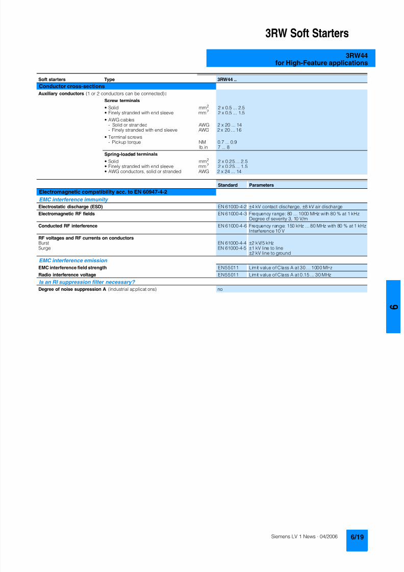
8122019 Arr Estado Solido
httpslidepdfcomreaderfullarr-estado-solido 2340
3RW Soft Starters
3RW44for High-Feature applications
Soft starters Type 3RW44
Conductor cross-sections
Auxiliary conductors (1 or 2 conductors can be connected)
Screw terminals
bull Solid mm2 2 x 05 25bull Finely stranded with end sleeve mm2 2 x 05 15
bull AWG cables- Solid or stranded AWG 2 x 20 14- Finely stranded with end sleeve AWG 2 x 20 16
bull Terminal screws- Pickup torque NM 07 09
lbin 7 8
Spring-loaded terminals
bull Solid mm2 2 x 025 25bull Finely stranded with end sleeve mm2 2 x 025 15bull AWG conductors solid or stranded AWG 2 x 24 14
Standard Parameters
Electromagnetic compatibility acc to EN 60947-4-2
EMC interference immunityElectrostatic discharge (ESD) EN 61000-4-2 plusmn4 kV contact discharge plusmn8 kV air discharge
Electromagnetic RF fields EN 61000-4-3 Frequency range 80 1000 MHz with 80 at 1 kHzDegree of severity 3 10 Vm
Conducted RF interference EN 61000-4-6 Frequency range 150 kHz 80 MHz with 80 at 1 kHzInterference 10 V
RF voltages and RF currents on conductorsBurst EN 61000-4-4 plusmn2 kV5 kHzSurge EN 61000-4-5 plusmn1 kV line to line
plusmn2 kV line to ground
EMC interference emission
EMC interference field strength EN55011 Limit value of Class A at 30 1000 MHz
Radio interference voltage EN55011 Limit value of Class A at 015 30 MHz
Is an RI suppression filter necessary
Degree of noise suppression A (industrial applications) no
8122019 Arr Estado Solido
httpslidepdfcomreaderfullarr-estado-solido 2440
3RW Soft Starters
3RW44for High-Feature applications
Fuse assignment
The coordination type to which the motor feeder with soft starteris mounted depends on the application-specific requirements
Normally fuseless mounting (combination of motor starter pro-tector and soft starter) is sufficient If type 2 coordination is to befulfilled semiconductor fuses must be fitted in the motor feeder
1) The rated motor current must be considered when selecting the devices
2) The types of coordination are explained in more detail in theTechnical information LV 1 T under ndash Fuseless Load Feeders
Inline circuit fuseless version
Soft starters Motor starter protectorscircuit-breakers1)
Rated current 440 V +10 Rated currentG1 Q1Type A Type A
Type of coordination 12) 3RW44 22 3RW44 27 I q = 32 kA 3RW44 34 and 3RW44 35 I q = 16 kA 3RW44 36 3RW44 57 I q = 65 kA
3RW44 22 29 3RV10 42-4HA10 503RW44 23 36 3RV10 42-4JA10 633RW44 24 47 3RV10 42-4KA10 75
3RW44 25 57 3RV10 42-4LA10 903RW44 26 77 3RV10 42-4MA10 1003RW44 27 93 3RV10 42-4MA10 100
3RW44 34 113 3VL17 16-2DD36 1603RW44 35 134 3VL17 16-2DD36 1603RW44 36 162 3VL37 25-2DC36 250
3RW44 43 203 3VL47 31-3DC36 3153RW44 44 250 3VL47 31-3DC36 3153RW44 45 313 3VL47 40-3DC36 400
3RW44 46 356 3VL47 40-3DC36 4003RW44 47 432 3VL57 50-3DC36 500
3RW44 53 551 3VL67 80-3DE36 8003RW44 54 615 3VL67 80-3DE36 8003RW44 55 693 3VL67 80-3DE36 800
3RW44 56 780 3VL77 10-3AB36 10003RW44 57 880 3VL77 10-3AB36 10003RW44 58 970 3VL77 12-3AB36 1200
8122019 Arr Estado Solido
httpslidepdfcomreaderfullarr-estado-solido 2540
3RW Soft Starters
3RW44for High-Feature applications
1) If the ramp-down function Combined braking is selected no brakingcontactor is requiredIf the ramp-down function DC braking is selected a braking contactormust also be used (see table for type)For applications with large centrifugal masses (J Load gt J Motor) werecommend the function DC braking
2) Additional auxiliary relay K4LZXRT4A4T30(3RW44 soft starter with rated control supply voltage 230 V AC)LZXRT4A4S15(3RW44 soft starter with rated control supply voltage 115 V AC)
3) The types of coordination are explained in more detail in theTechnical information LV 1 T under ndash Fuseless Load Feeders
Inline circuit fused version (line protection only)
Soft starters Line protections Line contactorsup to 400 V
Braking contactors1)2)
Rated current 690 V +5 Rated current Size (optional) (for typical circuit see page 633)G1 F1 K1 K2 K3Type A Type A Type Type Type
Type of coordination 13) I q = 65 kA
3RW44 22 29 3NA3 820-6 50 00 3RT10 34 3RT15 26 --3RW44 23 36 3NA3 822-6 63 00 3RT10 35 3RT15 26 --
3RW44 24 47 3NA3 824-6 80 00 3RT10 36 3RT15 35 --3RW44 25 57 3NA3 830-6 100 00 3RT10 44 3RT15 35 --3RW44 26 77 3NA3 132-6 125 1 3RT10 45 3RT10 24 3RT10 353RW44 27 93 3NA3 136-6 160 1 3RT10 46 3RT10 25 3RT10 36
3RW44 34 113 3NA3 244-6 250 2 3RT10 54 3RT10 34 3RT10 443RW44 35 134 3NA3 244-6 250 2 3RT10 55 3RT10 36 3RT10 453RW44 36 162 3NA3 365-6 500 3 3RT10 56 3RT10 44 3RT10 45
3RW44 43 203 2 x 3NA3 354-6 2 x 355 3 3RT10 64 3RT10 44 3RT10 543RW44 44 250 2 x 3NA3 354-6 2 x 355 3 3RT10 65 3RT10 44 3RT10 553RW44 45 313 2 x 3NA3 365-6 2 x 500 3 3RT10 75 3RT10 54 3RT10 56
3RW44 46 356 2 x 3NA3 365-6 2 x 500 3 3RT10 75 3RT10 54 3RT10 563RW44 47 432 2 x 3NA3 365-6 2 x 500 3 3RT10 76 3RT10 55 3RT10 64
3RW44 53 551 2 x 3NA3 365-6 2 x 500 3 3TF68 44-0CM7 3TF68 44-0CM7 3TF68 44-0CM73RW44 54 615 2 x 3NA3 365-6 2 x 500 3 3TF68 44-0CM7 3TF68 44-0CM7 3TF68 44-0CM73RW44 55 693 2 x 3NA3 365-6 2 x 500 3 3TF69 44-0CM7 3TF69 44-0CM7 3TF69 44-0CM7
3RW44 56 780 2 x 3NA3 365-6 2 x 500 3 3TF69 44-0CM7 3TF69 44-0CM7 3TF69 44-0CM73RW44 57 880 2 x 3NA3 365-6 2 x 500 3 2 x 3TF69 44-0CM7 2 x 3TF69 44-0CM7 2 x 3TF69 44-0CM7
3RW44 58 970 3 x 3NA3 365-6 3 x 500 3
8122019 Arr Estado Solido
httpslidepdfcomreaderfullarr-estado-solido 2640
3RW Soft Starters
3RW44for High-Feature applications
1) If the ramp-down function Combined braking is selected no brakingcontactor is requiredIf the ramp-down function DC braking is selected a braking contactormust also be used (see table for type)For applications with large centrifugal masses (J Load gt J Motor) werecommend the function DC braking
2) Additional auxiliary relay K4LZXRT4A4T30(3RW44 soft starter with rated control supply voltage 230 V AC)LZXRT4A4S15(3RW44 soft starter with rated control supply voltage 115 V AC)
3) The types of coordination are explained in more detail in theTechnical information LV 1 T under ndash Fuseless Load Feeders
Inline circuit fused version with 3NE1 SITOR all-range fuse (semiconductor and line protection)
Soft starters All-range fuses Line contactors upto 400 V
Braking contactors1)2)
Ratedcurrent
Rated current Voltage Size (optional) (for typical circuit see page 633)
G1 Frsquo1 K1 K2 K3Type A Type A V Type Type Type
Type of coordination 23) I q = 65 kA
3RW44 22 29 3NE1 020-2 80 690 +5 00 3RT10 34 3RT15 26 --
3RW44 23 36 3NE1 020-2 80 690 +5 00 3RT10 35 3RT15 26 --3RW44 24 47 3NE1 021-2 100 690 +5 00 3RT10 36 3RT15 35 --
3RW44 25 57 3NE1 022-2 125 690 +5 00 3RT10 44 3RT15 35 --3RW44 26 77 3NE1 022-2 125 690 +5 00 3RT10 45 3RT10 24 3RT10 353RW44 27 93 3NE1 024-2 160 690 +5 1 3RT10 46 3RT10 25 3RT10 36
3RW44 34 113 3NE1 225-2 200 690 +5 1 3RT10 54 3RT10 34 3RT10 443RW44 35 134 3NE1 227-2 250 690 +5 1 3RT10 55 3RT10 36 3RT10 453RW44 36 162 3NE1 227-2 250 690 +5 1 3RT10 56 3RT10 44 3RT10 45
3RW44 43 203 3NE1 230-2 315 600 +10 1 3RT10 64 3RT10 44 3RT10 543RW44 44 250 3NE1 331-2 350 460 +10 2 3RT10 65 3RT10 44 3RT10 553RW44 45 313 3NE1 333-2 450 690 +5 2 3RT10 75 3RT10 54 3RT10 56
3RW44 46 356 3NE1 334-2 500 690 +5 2 3RT10 75 3RT10 54 3RT10 563RW44 47 432 3NE1 435-2 560 690 +5 3 3RT10 76 3RT10 55 3RT10 64
3RW44 53 551 2 x 3NE1 334-2 500 690 +10 2 3TF68 44-0CM7 3TF68 44-0CM7 3TF68 44-0CM73RW44 54 615 2 x 3NE1 334-2 500 690 +10 2 3TF68 44-0CM7 3TF68 44-0CM7 3TF68 44-0CM73RW44 55 693 2 x 3NE1 334-2 500 690 +10 2 3TF69 44-0CM7 3TF69 44-0CM7 3TF69 44-0CM7
3RW44 56 780 2 x 3NE1 435-2 560 690 +10 3 3TF69 44-0CM7 3TF69 44-0CM7 3TF69 44-0CM7
3RW44 57 880 2 x 3NE1 435-2 560 690 +10 3 2 x 3TF69 44-0CM7 2 x 3TF69 44-0CM7 2 x 3TF69 44-0CM73RW44 58 970 2 x 3NE1 435-2 560 690 +10 3
8122019 Arr Estado Solido
httpslidepdfcomreaderfullarr-estado-solido 2740
3RW Soft Starters
3RW44for High-Feature applications
1) If the ramp-down function Combined braking is selected no brakingcontactor is requiredIf the ramp-down function DC braking is selected a braking contactor
must also be used (see table for type)For applications with large centrifugal masses (J Load gt J Motor) werecommend the function DC braking
2) Additional auxiliary relay K4LZXRT4A4T30(3RW44 soft starter with rated control supply voltage 230 V AC)
LZXRT4A4S15(3RW44 soft starter with rated control supply voltage 115 V AC)
3) The types of coordination are explained in more detail in theTechnical information LV 1 T under ndash Fuseless Load Feeders
Inline circuit fused version with 3NE or 3NC SITOR semiconductor fuse(semiconductor protection by fuse lead and overload protection by circuit-breaker)
Soft starters Semiconductor fuses minimum Semiconductor fuses maximum Semiconductor fuses (cylinder)
Ratedcurrent
Rated current Size Rated current Size Rated current Size
G1 F3 F3 F3Type A Type A Type A Type A
Type of coordination 23) I q = 65 kA
3RW44 22 29 3NE4 120 80 0 3NE4 121 100 0 3NC2 280 80 22 x 58
3RW44 23 36 3NE4 121 100 0 3NE4 122 125 0 3NC2 200 100 22 x 583RW44 24 47 3NE4 121 100 0 3NE4 122 125 0 3NC2 200 100 22 x 58
3RW44 25 57 3NE4 122 125 0 3NE4 124 160 03RW44 26 77 3NE4 124 160 0 3NE4 124 160 03RW44 27 93 3NE3 224 160 1 3NE3 333 450 2
3RW44 34 113 3NE3 225 200 1 3NE3 335 560 23RW44 35 134 3NE3 225 200 1 3NE3 335 560 23RW44 36 162 3NE3 227 250 1 3NE3 333 450 2
3RW44 43 203 3NE3 230-0B 315 1 3NE3 333 450 23RW44 44 250 3NE3 230-0B 315 1 3NE3 333 450 23RW44 45 313 3NE3 233 450 1 3NE3 336 630 2
3RW44 46 356 3NE3 333 450 2 3NE3 336 630 23RW44 47 432 3NE3 335 560 2 3NE3 338-8 800 2
3RW44 53 551 2 x 3NE3 335 560 2 3 x 3NE3 334-0B 500 23RW44 54 615 2 x 3NE3 335 560 2 3 x 3NE3 334-0B 500 23RW44 55 693 2 x 3NE3 335 560 2 3 x 3NE3 334-0B 500 2
3RW44 56 780 2 x 3NE3 336 630 2 2 x 3NE3 340-8 900 2
3RW44 57 880 2 x 3NE3 336 630 2 2 x 3NE3 340-8 900 23RW44 58 970 2 x 3NE3 336 630 2 2 x 3NE3 340-8 900 2
Soft starters Line contactorsup to 400 V
Braking contactors1)2) Motor starter protectors circuit-breakers
Max line protection
Ratedcurrent
(optional) (for typical circuit see page 633) 440 V +10 Rated current 690 V +5 Rated current Size
G1 K1 Q1 F1Type A Type Type Type Type A Type A
Type of coordination 23) 3RW44 22 3RW44 27 I q = 32 kA 3RW44 34 and 3RW44 35 I q = 16 kA 3RW44 36 3RW44 57 I q = 65 kA
3RW44 22 29 3RT10 34 3RT15 26 -- 3RV10 41-4HA10 50 3NA3 820-6 50 003RW44 23 36 3RT10 35 3RT15 26 -- 3RV10 41-4JA10 63 3NA3 822-6 63 003RW44 24 47 3RT10 36 3RT15 35 -- 3RV10 41-4KA10 75 3NA3 824-6 80 00
3RW44 25 57 3RT10 44 3RT15 35 -- 3RV10 41-4LA10 90 3NA3 830-6 100 003RW44 26 77 3RT10 45 3RT10 24 3RT10 35 3RV10 41-4MA10 100 3NA3 132-6 125 13RW44 27 93 3RT10 46 3RT10 25 3RT10 36 3RV10 41-4MA10 100 3NA3 136-6 160 1
3RW44 34 113 3RT10 54 3RT10 34 3RT10 44 3VL17 16-1DD36 160 3NA3 244-6 250 2
3RW44 35 134 3RT10 55 3RT10 36 3RT10 45 3VL17 16-1DD36 160 3NA3 244-6 250 23RW44 36 162 3RT10 56 3RT10 44 3RT10 45 3VL37 25-1DC36 250 3NA3 365-6 500 3
3RW44 43 203 3RT10 64 3RT10 44 3RT10 54 3VL47 31-1DC36 315 2 x 3NA3 354-6 2 x 355 33RW44 44 250 3RT10 65 3RT10 44 3RT10 55 3VL47 31-1DC36 315 2 x 3NA3 354-6 2 x 355 33RW44 45 313 3RT10 75 3RT10 54 3RT10 56 3VL47 40-1DC36 400 2 x 3NA3 365-6 2 x 500 3
3RW44 46 356 3RT10 75 3RT10 54 3RT10 56 3VL47 40-1DC36 400 2 x 3NA3 365-6 2 x 500 33RW44 47 432 3RT10 76 3RT10 55 3RT10 64 3VL57 50-1DC36 500 2 x 3NA3 365-6 2 x 500 3
3RW44 53 551 3TF68 44-0CM7 3TF68 44-0CM7 3TF68 44-0CM7 3VL67 80-1AB36 800 2 x 3NA3 365-6 2 x 500 33RW44 54 615 3TF68 44-0CM7 3TF68 44-0CM7 3TF68 44-0CM7 3VL67 80-1AB36 800 2 x 3NA3 365-6 2 x 500 33RW44 55 693 3TF69 44-0CM7 3TF69 44-0CM7 3TF69 44-0CM7 3VL67 80-1AB36 800 2 x 3NA3 365-6 2 x 500 3
3RW44 56 780 3TF69 44-0CM7 3TF69 44-0CM7 3TF69 44-0CM7 3VL77 10-1AB36 1000 2 x 3NA3 365-6 2 x 500 33RW44 57 880 2 x
3TF69 44-0CM72 x3TF69 44-0CM7
2 x3TF69 44-0CM7
3VL77 10-1AB36 1000 2 x 3NA3 365-6 2 x 500 3
3RW44 58 970 3VL77 12-1AB36 1200 3 x 3NA3 365-6 3 x 500 3
8122019 Arr Estado Solido
httpslidepdfcomreaderfullarr-estado-solido 2840
3RW Soft Starters
3RW44for High-Feature applications
1) The types of coordination are explained in more detail in theTechnical information LV 1 T under ndash Fuseless Load FeedersThe type of coordination 2 only refers to soft starters not to feeder compo-nents ( I q = 65 kA)
Inside-delta circuit fused version with 3NE or 3NC SITOR fuses(semiconductor protection by fuse lead and overload protection by circuit-breaker)
Soft starters Semiconductor fuses minimum Semiconductor fuses maximum Semiconductor fuses (cylinder)
Ratedcurrent
Rated current Size Rated current Size Rated current Size
G1 F3 F3 F3Type A Type A Type A Type A
Type of coordination 21)
3RW44 22 50 3NE4 120 80 0 3NE4 121 100 0 3NC2 280 80 22 x 58
3RW44 23 62 3NE4 121 100 0 3NE4 122 125 0 3NC2 200 100 22 x 583RW44 24 81 3NE4 121 100 0 3NE4 122 125 0 3NC2 200 100 22 x 58
3RW44 25 99 3NE4 122 125 0 3NE4 124 160 03RW44 26 133 3NE4 124 160 0 3NE4 124 160 03RW44 27 161 3NE3 224 160 1 3NE3 333 450 2
3RW44 34 196 3NE3 225 200 1 3NE3 335 560 23RW44 35 232 3NE3 225 200 1 3NE3 335 560 23RW44 36 281 3NE3 227 250 1 3NE3 333 450 2
3RW44 43 352 3NE3 230-0B 315 1 3NE3 333 450 23RW44 44 433 3NE3 230-0B 315 1 3NE3 333 450 23RW44 45 542 3NE3 233 450 1 3NE3 336 630 2
3RW44 46 617 3NE3 333 450 2 3NE3 336 630 23RW44 47 748 3NE3 335 560 2 3NE3 338-8 800 2
3RW44 53 954 2 x 3NE3 335 560 2 3 x 3NE3 334-0B 500 23RW44 54 1065 2 x 3NE3 335 560 2 3 x 3NE3 334-0B 500 23RW44 55 1200 2 x 3NE3 335 560 2 3 x 3NE3 334-0B 500 2
3RW44 56 1351 2 x 3NE3 336 630 2 2 x 3NE3 340-8 900 2
3RW44 57 1524 2 x 3NE3 336 630 2 3 x 3NE3 340-8 900 23RW44 58 1680 2 x 3NE3 336 630 2 3 x 3NE3 340-8 900 2
Soft starters Line contactorsup to 400 V
Motor starter protectors cirduit-breakers
Line protections
Ratedcurrent
(optional) 440 V +10 Rated current 690 V +5 Rated current Size
G1 K1 Q1 F1Type A Type Type A Type A
Type of coordination 21)
3RW44 22 50 3RT10 36-1AP04 3RV10 4-4KA10 75 3NA3 824-6 80 003RW44 23 62 3RT10 44-1AP04 3RV10 4-4LA10 90 3NA3 830-6 100 003RW44 24 81 3RT10 46-1AP04 3RV10 4-4MA10 100 3NA3 132-6 125 1
3RW44 25 99 3RT10 54-1AP36 3VL27 16-DC36 160 3NA3 136-6 160 13RW44 26 133 3RT10 55-6AP36 3VL27 16-DC36 160 3NA3 240-6 200 23RW44 27 161 3RT10 56-6AP36 3VL37 20-DC36 200 3NA3 244-6 250 2
3RW44 34 196 3RT10 64-6AP36 3VL37 25-DC36 250 3NA3 360-6 400 3
3RW44 35 232 3RT10 65-6AP36 3VL47 31-DC36 315 3NA3 360-6 400 33RW44 36 281 3RT10 66-6AP36 3VL47 40-DC36 400 2 x 3NA3 360-6 2 x 400 3
3RW44 43 352 3RT10 75-6AP36 3VL47 40-DC36 400 2 x 3NA3 365-6 2 x 500 33RW44 44 433 3RT10 76-6AP36 3VL57 50-DC36 500 2 x 3NA3 365-6 2 x 500 33RW44 45 542 3TF68 44-0CM7 3VL57 63-DC36 800 3 x 3NA3 365-6 3 x 500 3
3RW44 46 617 3TF68 44-0CM7 3VL67 80-AB36 800 3 x 3NA3 365-6 3 x 500 33RW44 47 748 3TF69 3VL67 80-AB36 1000 3 x 3NA3 365-6 3 x 500 3
3RW44 53 954 2 x 3TF68 44-0CM7 3VL77 10-AB36 1000 3 x 3NA3 365-6 3 x 500 33RW44 54 1065 2 x 3TF68 44-0CM7 3VL77 12-AB36 1250 3 x 3NA3 365-6 3 x 500 33RW44 55 1200 2 x 3TF69 44-0CM7 3VL87 16-AB36 1600 3 x 3NA3 365-6 3 x 500 3
3RW44 56 1351 2 x 3TF69 44-0CM7 3VL87 16-AB36 1600 3 x 3NA3 372 3 x 630 33RW44 57 1524 2 x 3TF69 44-0CM7 3VL87 16-AB36 1600 3 x 3NA3 372 3 x 630 33RW44 58 1680 3WL12 20 2000 2 x 3NA3 480 2 x 1000 4
8122019 Arr Estado Solido
httpslidepdfcomreaderfullarr-estado-solido 2940
3RW Soft Starters
3RW44for High-Feature applications
Characteristic curves
Motor protection tripping characteristics for 3RW44(with symmetry)
Admissible mounting height
The admissible operational voltage is reduced to 460 V with a mountingheight of more than 2000 m
Motor protection characteristics for 3RW44(with phase unbalance)
e
2 4 6 101
Class 10 Class 15 Class 20
100
101
102
103
2
4
6
2
4
6
2
4
6
Class 5 Class 30
N S B 0
_ 0 1 5 0 0 a
[ s ]
x
T r i p p i n g t i m e
85
105
70
75
80
90
95
100
N S B 0
_ 0 1 7 0 4
0 1000 2000 3000 4000 5000 O p e r
a t i o n a
l r a
t e d c u r r e n
t I
i n
Mounting height in m
e
e
1001
Class 10 Class 15 Class 20
100
101
102
103
2
4
6
2
4
6
2
4
6
Class 5 Class 30
N S B 0
_ 0 1 7 0 6
[ s ]
x10
T r i p p
i n g
t i m e
8122019 Arr Estado Solido
httpslidepdfcomreaderfullarr-estado-solido 3040
3RW Soft Starters
3RW44for High-Feature applications
More information
Application examples for normal starting (Class 10)
Application examples for heavy starting (Class 20)
Application examples for very heavy starting (Class 30)
NoteThese tables present sample setting values and device sizesThey are intended only for the purposes of information and arenot binding The setting values depend on the application inquestion and must be optimized during commissioningThe soft starter dimensions should be checked where necessarywith the Win-Soft Starter software or with the help ofTechnical Assistance
Normal starting Class 10 (up to 20 s with 350 I n motor)The soft starter rating can be selected to be as high as the rating of the motor used
Application Conveyor belts Roller conveyors Compressors Small ventilators Pumps Hydraulic pumps
Starting parameters
bull Voltage ramp and currentlimiting- Starting voltage 70 60 50 30 30 30- Starting time s 10 10 10 10 10 10- Current limit value Deactivated Deactivated 4 x I M 4 x I M Deactivated Deactivated
bull Torque ramp- Starting torque 60 50 40 20 10 10- End torque 150 150 150 150 150 150- Starting time 10 10 10 10 10 10
bull Breakaway pulse Deactivated (0 ms) Deactivated (0 ms) Deactivated (0 ms) Deactivated (0 ms) Deactivated (0 ms) Deactivated (0 ms)
Ramp-down mode Smoothramp-down
Smoothramp-down
Free ramp-down Free ramp-down Pump ramp-down Free ramp-down
Heavy starting Class 20 (up to 40 s with 350 I n motor)The soft starter has to be selected one rating class higher than the motor used
Application Stirrers Centrifuges Milling machines
Starting parameters
bull Voltage ramp and currentlimiting- Starting voltage 30 30 30- Starting time s 30 30 30- Current limit value 4 x I M 4 x I M 4 x I M
bull Torque ramp- Starting torque 30 30 30- End torque 150 150 150- Starting time 30 30 30
bull Breakaway pulse Deactivated (0 ms) Deactivated (0 ms) Deactivated (0 ms)
Ramp-down mode Free ramp-down Free ramp-down Free ramp-down or DC braking
Very heavy starting Class 30 (up to 60 s with 350 I n motor)The soft starter has to be selected two rating classes higher than the motor used
Application Large ventilators Mills Breakers Circular sawbandsaws
Starting parameters
bull Voltage ramp and currentlimiting- Starting voltage 30 50 50 30- Starting time s 60 60 60 60- Current limit value 4 x I M 4 x I M 4 x I M 4 x I M
bull Torque ramp- Starting torque 20 50 50 20- End torque 150 150 150 150- Starting time 60 60 60 60
bull Breakaway pulse Deactivated (0 ms) 80 300 ms 80 300 ms Deactivated (0 ms)
Ramp-down mode Free ramp-down Free ramp-down Free ramp-down Free ramp-down
8122019 Arr Estado Solido
httpslidepdfcomreaderfullarr-estado-solido 3140
3RW Soft Starters
3RW44for High-Feature applications
Circuit concept
The SIRIUS 3RW44 soft starters can be operated in two differenttypes of circuit
bull Inline circuitThe controls for isolating and protecting the motor are simplyconnected in series with the soft starter The motor isconnected to the soft starter with three leads
bull Inside-delta circuitThe wiring is similar to that of wye-delta starters The phases ofthe soft starter are connected in series with the individual motorwindings The soft starter then only has to carry the phasecurrent amounting to about 58 of the rated motor current(conductor current)
Comparison of the types of circuit
Inline circuitRated current I e corresponds to the rated motor current I n3 leads to the motor
Inside-delta circuit
Rated current I e corresponds to approx 58 of the rated motorcurrent I n6 leads to the motor (as with wye-delta starters)
Which circuit
Using the inline circuit involves the lowest wiring complexityIf the soft starter to motor connections are long this contactsequence is preferableWith the inside-delta circuit there is double the wiring complexitybut a smaller size of device can be used at the same rating
Thanks to choosing the operational mode between the inline cir-cuit and inside-delta circuit the most favorable solution can al-ways be chosen
The braking function is possible only in the inline circuit
Configuration
The 3RW44 solid-state soft starters are designed for normalstarting In case of heavy starting or increased starting
frequency a larger device must be selectedFor long starting times it is recommended to have a PTC ther-mistor detector in the motor This also applies for the ramp-downmodes smooth ramp-down pump ramp-down and DC brakingbecause during the ramp-down time in these modes an addi-tional current loading applies in contrast to free ramp-down
In the motor feeder between the SIRIUS 3RW soft starter and themotor no capacitive elements are permitted (eg no reactive-power compensation equipment) In addition neither staticsystems for reactive-power compensation nor dynamic PFC(Power Factor Correction) must be operated in parallel duringstarting and ramp-down of the soft starter This is important toprevent faults arising on the compensation equipment andor thesoft starter
All elements of the main circuit (such as fuses and controls)
should be dimensioned for direct starting following the localshort-circuit conditions Fuses switching devices and overloadrelays must be ordered separately
The harmonic component load for starting currents must betaken into consideration for the selection of motor starterprotectors (selection of release)
NoteWhen switching on three-phase current motors voltage dropsnormally will occur with all types of starters (direct starters star- delta starters soft starters) On principle the feeding transformermust be configured such that when starting the motor thevoltage drop must occur within the admissible tolerance Whenthe feeding transformer is designed quite scarce the control vol- tage (being independent of the main voltage) should be sup- plied with a separate circuit in order to prevent the soft starterfrom switching off
Serial PC interface PROFIBUS DP communication moduleand parameterizing and operating software Soft Starter ES
The solid-state 3RW44 soft starters have a PC interface forcommunicating with the Soft Starter ES 2006 Smart software orto be connected to an external operating and monitoring mod-ule When using the optional communication module PROFIBUSthe 3RW44 soft starter can be connected to the PROFIBUS netand can communicate via GSD file or software Soft Starter ES2006 Professional
Manual for SIRIUS 3RW44
Besides containing all important information on planning com-missioning and servicing the manual also contains suggestedcircuits and the technical specifications for all devices
Win-Soft Starter selection and simulation program
With this software you can simulate and select all Siemens softstarters taking into account various parameters such as mainsproperties motor and load data and special applicationrequirements
The software is a valuable tool which makes complicatedlengthy manual calculations for determining the required softstarters superfluous
You can order the CD-ROM under the following order numberOrder No E20001-D1020-P302-V2-7400
More information can be found on the Internet athttpwwwsiemenscomsoftstarter
8122019 Arr Estado Solido
httpslidepdfcomreaderfullarr-estado-solido 3240
3RW Soft Starters
3RW44for High-Feature applications
SIRIUS soft starter training course (SD-SIRIUSO)
Siemens offers a 2-day training course on the SIRIUS solid-statesoft starters to keep customers and own personnel up-to-date on
configuring commissioning and servicing issuesPlease direct enquiries and applications to
AampD PT 4 (Trainings-Center Erlangen)Werner-von-Siemens-Str 65D-91052 ErlangenTelefon ++49 9131 729262Telefax ++49 9131 728172sibrainindustrysiemenscomhttp wwwsiemenscomsitrain
8122019 Arr Estado Solido
httpslidepdfcomreaderfullarr-estado-solido 3340
3RW Soft Starters
Project planning aids
Dimensional drawings
3RW44 2 3RW44 3 and 3RW44 4 for High-Feature applications
TypeDimension(mm)
a b c d e f g h I k l m n o p q
3RW44 2 180 170 37 11 167 100 240 270 180 148 75 153 7 184 66 M6 10 Nm
3RW44 3 180 170 37 17 167 100 240 270 180 148 75 153 7 198 9 M6 10 Nm
3RW44 4 210 210 48 25 190 140 269 298 205 166 16 166 9 230 11 M8 15 Nm
8122019 Arr Estado Solido
httpslidepdfcomreaderfullarr-estado-solido 3440
3RW Soft Starters
Project planning aids
3RW44 5 for High-Feature applications
147
173
195
118
N S B 0_
0 1 6 5 3
261
290
249
162
152
6 2 3
1 0 5
2 5 3
1 6 5
76
44
470
510
1
5 5
2
0Oslash14 40
6 3 8 5
5 9 0
8122019 Arr Estado Solido
httpslidepdfcomreaderfullarr-estado-solido 3540
3RW Soft Starters
Project planning aids
Schematics
1) Permissible values for main and control voltagesee Technical Specifications
3RW44 connection examples for main and control circuits
Main circuit Control circuitPossibility 1a Possibility 1Inline circuit with circuit-breaker and SITOR fuse(semiconductor protection only)
Control by pushbutton
Main circuit
Possibility 1b Possibility 1cInline circuit with full-rangeprotection (line andsemiconductor protection)
Inline circuit with line andSITOR fuse(semiconductor protection only)
Q1
L3L2L1
G1
F3
T1 T2 T3
M1
N S B 0_
0 1 4 9 0 a
L1 L2 L3
V1U1 W1
MPE 3~
3NPE 400 V AC 50 Hz
(optionalsemiconductorprotection fuse)
13 14 23 24 33 34 95 9896 +
T1 T2IN4IN3IN2IN1L-L+A1
A2
NPE
PE
G1
F2
NSB0_01494a
S t a r t
S 2
R e s e t S
3
StopS1
L1
On periodGrouperror
N o a c t i o n
N o a c t i o n
Noaction
PTC type Aor
Thermoclick
Noaction
1NPE 230 V AC 50 Hz
M o t o r o
n r i g h t
P S
1
1)
8122019 Arr Estado Solido
httpslidepdfcomreaderfullarr-estado-solido 3640
3RW Soft Starters
Project planning aids
1) Permissible values for main and control voltagesee Technical Specifications
2) Caution Risk of restartingThe start command (eg from the PLC) must be reset prior to a resetcommand because a new automatic restart will take place automaticallyif a start command is active after the reset command This appliesespecially in case of motor protection trippingFor safety reasons we recommend incorporating the group error output(terminals 95 and 96) in the controller
Main circuit Control circuit
Possibility 2 Possibility 2Inline circuit with main contactor Control of a main contactor and control by means of PLC
Q1
L3L2L1
G1
K1
F3
L1 L2 L3
T1 T2 T3
M1
N S B 0_
0 1 4 9 5 a
V1U1 W1
MPE 3~
1)
(optionalsemiconductorprotection)
(optional linecontactor if floatingswitching of themotor is planned)
3NPE 400 V AC 50 Hz
13 14 23 24 33 34 95 9896+
T1 T2IN4IN3IN2IN1L-L+A1
A2
NPE
PE
G1
K1NSB0_01496a
F2+24 V DC
M
L1 1NPE AC 230 V 50 Hz1)
Switch-on duration
M o t o r r i g h t
T r i p R e s e t
PLC outputs PLC inputs
N o a c t i o n
N o a c t i o n
No action No action
Group error
PTC type A Thermoclick
(optional line contactorif floating switchingof the motor is planned)
P S 1
ResetStart 2)
8122019 Arr Estado Solido
httpslidepdfcomreaderfullarr-estado-solido 3740
3RW Soft Starters
Project planning aids
1) Permissible values for main and control voltagesee Technical Specifications
2) Caution Risk of restartingThe start command (eg from the PLC) must be reset prior to a resetcommand because a new automatic restart will take place automaticallyif a start command is active after the reset command This applies espe-cially in case of motor protection trippingFor safety reasons we recommend incorporating the group error output(terminals 95 and 96) in the controller
3) If the ramp-down function Combined braking is selected no brakingcontactor is requiredIf the ramp-down function DC braking is selected a braking contactormust be used in addition Type see Fuse Coordination (inline circuit) onpages 621 to 623For applications with large centrifugal masses (J Load gt J Motor) werecommend the function DC brakingThe output 2 must be switched over to DC braking contactor
4) Auxiliary relay K4 egLZXRT4A4T30 (230 V AC rated control supply voltage)LZXRT4A4S15 (115 V AC rated control supply voltage)
Main circuit Control circuit
Possibility 3a Possibility 3aInline circuit with ramp-down function DC braking3)
(for device types 3RW44 22 to 3RW44 25)Control of the braking contactor3)
Main circuit Control circuit
Possibility 3b Possibility 3bInline circuit with ramp-down function DC braking3)
(for device types 3RW44 26 to 3RW44 47)Control of the braking contactor3)
Q1
L3L2
G1
F3
T1 T2 T3
M1
N S B 0_
0 1 5 0 1 a
L1 L2 L3
V1U1 W1
M
K2 K2 K2
PE 3~
1)
2
(optionalsemi-conductorprotection)
L1 3NPE 400 V AC 50 Hz
13 14 23 24 33 34 95 9896 +
T1 T2IN4IN3IN2IN1L-L+A1
A2
NPE
PEG1
K2NSB0_01502
R e s e t
M Start Reset
+24 V DC
K2
F2
1)
2)
No action Group error
N o a c t i o n
N o a c t i o n
On period
PLC output
PTC type Aor
Thermoclick
L1 1NPE 230 V AC 50 Hz
DC braking contactor 3)
K2 K33 3
G1
F3
T1 T2 T3
M1
N S B 0_
0 1
5 0 3 a
L1 L2 L3
V1U1 W1
MPE 3~
Q1
L3L2
1)
(optionalsemi-conductorprotection)
L1 3NPE 400 V AC 50 Hz
13 14 23 24 33 34 95 9896 +
T1 T2IN4IN3IN2IN1L-L+A1
A2
NPE
PE
G1
K4
NSB0_01504
R e s e t
K4 K4
K3 K2
K2 K3
+24 V DC
M Start Reset
F2
1)
2)
4)
PLC output
No action Group error
N o a c t i o n
N o a c t i o n
ON period
PTC type Aor
Thermoclick
M o t o r o n r i g h t
L1 1NPE 230 V AC 50 Hz
DC braking contactor 3)
8122019 Arr Estado Solido
httpslidepdfcomreaderfullarr-estado-solido 3840
3RW Soft Starters
Notes
1) Permissible values for main and control voltagesee Technical Specifications
2) Caution Risk of restartingThe start command (eg from the PLC) must be reset prior to a resetcommand because a new automatic restart will take place automaticallyif a start command is active after the reset command This appliesespecially in case of motor protection trippingFor safety reasons we recommend incorporating the group error output(terminals 95 and 96) in the controller
Main circuit Control circuit
Possibility 4a Possibility 4b Possibility 4Inside-delta circuit Change of direction of rotation for
inside-delta circuitControl by means of PLC
13 14 23 24 33 34 95 9896+
T1 T2IN4IN3IN2IN1L-L+A1
A2
NPE
PEG1
NSB0_01498a
+24 V DC
M
F2
L1 1NPE AC 230 V 50 Hz1)
2)
R e s e t
Switch-onduration
No action
Group error
N o a c t i o n
N o a c t i o n
No action
PTC type A orThermoclick
M o t o r r i g h t
PLC outputs PLC inputs
Start Reset
7
8122019 Arr Estado Solido
httpslidepdfcomreaderfullarr-estado-solido 3940
Appendix
Conditions of sale and delivery
Terms and Conditions of Sale and Delivery
By using this catalog you can acquire hardware and softwareproducts described therein from the Siemens AG subject to the
following terms Please note The scope the quality and the con-ditions for supplies and services including software productsby any Siemens entity having a registered office outside of Ger-many shall be subject exclusively to the General Terms andConditions of the respective Siemens entity
For customers with a seat or registered office in theFederal Republic of Germany
The bdquoGeneral Terms of Paymentldquo as well as the bdquoGeneral Condi-tions for the Supply of Products and Services of the Electricaland Electronics Industryldquo shall apply
For software products the bdquoGeneral License Conditions for Soft-ware Products for Automation and Drives for Customers with aSeat or registered Office in Germanyldquo shall apply
For customers with a seat or registered office outside of
Germany The bdquoGeneral Terms of Paymentldquo as well as the bdquoGeneral Condi-tions for Supplies of Siemens Automation and Drives for Cus-tomers with a Seat or registered Office outside of Germanyldquo shallapply
For software products the bdquoGeneral License Conditions for Soft-ware Products for Automation and Drives for Customers with aSeat or registered Office outside of Germanyldquo shall apply
General
The prices are in 991404 (Euro) ex works exclusive packaging
The sales tax (value added tax) is not included in the pricesIt shall be debited separately at the respective rate according tothe applicable legal regulations
In addition to the prices of products which include silver plump
aluminum andor copper surcharges may be calculated if therespective limits of the notes are exceeded The respective note(eg source German newspaper bdquoHandesblattldquo in categorybdquodeutsche Edelmetalleldquo and bdquoMetallverarbeiterldquo) for silver (bdquover-arbeitetes Silberldquo) plump (bdquoBlei in Kabelnldquo) aluminum (bdquoAlumin-ium in Kabelnldquo) and copper (bdquoElektrolytkupferldquo bdquoDEL-Notizldquo) re-spectively of the day the order or rather the on call order isreceived is decisive for the calculation of the surcharges
Surcharges of copper shall be calculated for Drives at a note(bdquoDEL-Notizldquo) above EUR 22500 100 Kg and for chokes trans-formers above EUR 15000 100 kg
Surcharges shall be charged based on the quantities of the ma-terials which are contained in the relevant products
Prices are subject to change without prior notice We will debitthe prices valid at the time of delivery
The dimensions are in mm In Germany according to the Ger-man law on units in measuring technology data in inches onlyapply to devices for export
Illustrations are not binding
Insofar as there are no remarks on the corresponding pages- especially with regard to data dimensions and weights given -these are subject to change without prior notice
Comprehensive Terms and Conditions of Sale and Delivery areavailable free of charge from your local Siemens business officeunder the following Order Nos
bull 6ZB5310-0KR30-0BA0(for customers based in the Federal Republic of Germany)
bull 6ZB5310-0KS53-0BA0(for customers based outside of theFederal Republic ofGermany)
or download them from the Internethttpwwwsiemenscomautomationmall (Germany AampD Mall Online-Help System)
Export regulations
The products listed in this catalog price list may be subject toEuropean German andor US export regulations
Therefore any export requiring a license is subject to approvalby the competent authorities
According to current provisions the following export regulations
must be observed with respect to the products featured in thiscatalog price list
Even without a label or with an ldquoAL Nldquo or ldquoECCN Nldquo authoriza-tion may be required due to the final destination and purpose forwhich the goods are to be used
The deciding factors are the AL or ECCN export authorizationindicated on order confirmations delivery notes and invoices
Errors excepted and subject to change without prior notice
AampDVuLEn 060306
AL Number of the German Export List
Products marked other than ldquoNldquo require an exportlicenseIn the case of software products the export des-ignations of the relevant data medium must alsobe generally adhered to
Goods labeled with an ldquoAL not equal to Nldquo aresubject to a European or German export authori-zation when being exported out of the EU
ECCN Export Control Classification Number
Products marked other than ldquoNldquo are subject to a
reexport license to specific countriesIn the case of software products the exportdesignations of the relevant data medium mustalso be generally adhered to
Goods labeled with an ldquoECCN not equal to Nldquo aresubject to a US re-export authorization
_ _ _ _
8122019 Arr Estado Solido
httpslidepdfcomreaderfullarr-estado-solido 4040
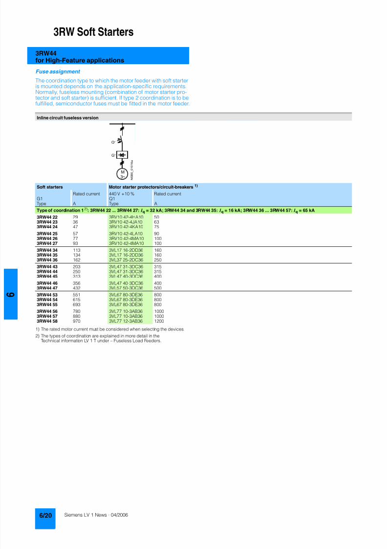
8122019 Arr Estado Solido
httpslidepdfcomreaderfullarr-estado-solido 2440
3RW Soft Starters
3RW44for High-Feature applications
Fuse assignment
The coordination type to which the motor feeder with soft starteris mounted depends on the application-specific requirements
Normally fuseless mounting (combination of motor starter pro-tector and soft starter) is sufficient If type 2 coordination is to befulfilled semiconductor fuses must be fitted in the motor feeder
1) The rated motor current must be considered when selecting the devices
2) The types of coordination are explained in more detail in theTechnical information LV 1 T under ndash Fuseless Load Feeders
Inline circuit fuseless version
Soft starters Motor starter protectorscircuit-breakers1)
Rated current 440 V +10 Rated currentG1 Q1Type A Type A
Type of coordination 12) 3RW44 22 3RW44 27 I q = 32 kA 3RW44 34 and 3RW44 35 I q = 16 kA 3RW44 36 3RW44 57 I q = 65 kA
3RW44 22 29 3RV10 42-4HA10 503RW44 23 36 3RV10 42-4JA10 633RW44 24 47 3RV10 42-4KA10 75
3RW44 25 57 3RV10 42-4LA10 903RW44 26 77 3RV10 42-4MA10 1003RW44 27 93 3RV10 42-4MA10 100
3RW44 34 113 3VL17 16-2DD36 1603RW44 35 134 3VL17 16-2DD36 1603RW44 36 162 3VL37 25-2DC36 250
3RW44 43 203 3VL47 31-3DC36 3153RW44 44 250 3VL47 31-3DC36 3153RW44 45 313 3VL47 40-3DC36 400
3RW44 46 356 3VL47 40-3DC36 4003RW44 47 432 3VL57 50-3DC36 500
3RW44 53 551 3VL67 80-3DE36 8003RW44 54 615 3VL67 80-3DE36 8003RW44 55 693 3VL67 80-3DE36 800
3RW44 56 780 3VL77 10-3AB36 10003RW44 57 880 3VL77 10-3AB36 10003RW44 58 970 3VL77 12-3AB36 1200
8122019 Arr Estado Solido
httpslidepdfcomreaderfullarr-estado-solido 2540
3RW Soft Starters
3RW44for High-Feature applications
1) If the ramp-down function Combined braking is selected no brakingcontactor is requiredIf the ramp-down function DC braking is selected a braking contactormust also be used (see table for type)For applications with large centrifugal masses (J Load gt J Motor) werecommend the function DC braking
2) Additional auxiliary relay K4LZXRT4A4T30(3RW44 soft starter with rated control supply voltage 230 V AC)LZXRT4A4S15(3RW44 soft starter with rated control supply voltage 115 V AC)
3) The types of coordination are explained in more detail in theTechnical information LV 1 T under ndash Fuseless Load Feeders
Inline circuit fused version (line protection only)
Soft starters Line protections Line contactorsup to 400 V
Braking contactors1)2)
Rated current 690 V +5 Rated current Size (optional) (for typical circuit see page 633)G1 F1 K1 K2 K3Type A Type A Type Type Type
Type of coordination 13) I q = 65 kA
3RW44 22 29 3NA3 820-6 50 00 3RT10 34 3RT15 26 --3RW44 23 36 3NA3 822-6 63 00 3RT10 35 3RT15 26 --
3RW44 24 47 3NA3 824-6 80 00 3RT10 36 3RT15 35 --3RW44 25 57 3NA3 830-6 100 00 3RT10 44 3RT15 35 --3RW44 26 77 3NA3 132-6 125 1 3RT10 45 3RT10 24 3RT10 353RW44 27 93 3NA3 136-6 160 1 3RT10 46 3RT10 25 3RT10 36
3RW44 34 113 3NA3 244-6 250 2 3RT10 54 3RT10 34 3RT10 443RW44 35 134 3NA3 244-6 250 2 3RT10 55 3RT10 36 3RT10 453RW44 36 162 3NA3 365-6 500 3 3RT10 56 3RT10 44 3RT10 45
3RW44 43 203 2 x 3NA3 354-6 2 x 355 3 3RT10 64 3RT10 44 3RT10 543RW44 44 250 2 x 3NA3 354-6 2 x 355 3 3RT10 65 3RT10 44 3RT10 553RW44 45 313 2 x 3NA3 365-6 2 x 500 3 3RT10 75 3RT10 54 3RT10 56
3RW44 46 356 2 x 3NA3 365-6 2 x 500 3 3RT10 75 3RT10 54 3RT10 563RW44 47 432 2 x 3NA3 365-6 2 x 500 3 3RT10 76 3RT10 55 3RT10 64
3RW44 53 551 2 x 3NA3 365-6 2 x 500 3 3TF68 44-0CM7 3TF68 44-0CM7 3TF68 44-0CM73RW44 54 615 2 x 3NA3 365-6 2 x 500 3 3TF68 44-0CM7 3TF68 44-0CM7 3TF68 44-0CM73RW44 55 693 2 x 3NA3 365-6 2 x 500 3 3TF69 44-0CM7 3TF69 44-0CM7 3TF69 44-0CM7
3RW44 56 780 2 x 3NA3 365-6 2 x 500 3 3TF69 44-0CM7 3TF69 44-0CM7 3TF69 44-0CM73RW44 57 880 2 x 3NA3 365-6 2 x 500 3 2 x 3TF69 44-0CM7 2 x 3TF69 44-0CM7 2 x 3TF69 44-0CM7
3RW44 58 970 3 x 3NA3 365-6 3 x 500 3
8122019 Arr Estado Solido
httpslidepdfcomreaderfullarr-estado-solido 2640
3RW Soft Starters
3RW44for High-Feature applications
1) If the ramp-down function Combined braking is selected no brakingcontactor is requiredIf the ramp-down function DC braking is selected a braking contactormust also be used (see table for type)For applications with large centrifugal masses (J Load gt J Motor) werecommend the function DC braking
2) Additional auxiliary relay K4LZXRT4A4T30(3RW44 soft starter with rated control supply voltage 230 V AC)LZXRT4A4S15(3RW44 soft starter with rated control supply voltage 115 V AC)
3) The types of coordination are explained in more detail in theTechnical information LV 1 T under ndash Fuseless Load Feeders
Inline circuit fused version with 3NE1 SITOR all-range fuse (semiconductor and line protection)
Soft starters All-range fuses Line contactors upto 400 V
Braking contactors1)2)
Ratedcurrent
Rated current Voltage Size (optional) (for typical circuit see page 633)
G1 Frsquo1 K1 K2 K3Type A Type A V Type Type Type
Type of coordination 23) I q = 65 kA
3RW44 22 29 3NE1 020-2 80 690 +5 00 3RT10 34 3RT15 26 --
3RW44 23 36 3NE1 020-2 80 690 +5 00 3RT10 35 3RT15 26 --3RW44 24 47 3NE1 021-2 100 690 +5 00 3RT10 36 3RT15 35 --
3RW44 25 57 3NE1 022-2 125 690 +5 00 3RT10 44 3RT15 35 --3RW44 26 77 3NE1 022-2 125 690 +5 00 3RT10 45 3RT10 24 3RT10 353RW44 27 93 3NE1 024-2 160 690 +5 1 3RT10 46 3RT10 25 3RT10 36
3RW44 34 113 3NE1 225-2 200 690 +5 1 3RT10 54 3RT10 34 3RT10 443RW44 35 134 3NE1 227-2 250 690 +5 1 3RT10 55 3RT10 36 3RT10 453RW44 36 162 3NE1 227-2 250 690 +5 1 3RT10 56 3RT10 44 3RT10 45
3RW44 43 203 3NE1 230-2 315 600 +10 1 3RT10 64 3RT10 44 3RT10 543RW44 44 250 3NE1 331-2 350 460 +10 2 3RT10 65 3RT10 44 3RT10 553RW44 45 313 3NE1 333-2 450 690 +5 2 3RT10 75 3RT10 54 3RT10 56
3RW44 46 356 3NE1 334-2 500 690 +5 2 3RT10 75 3RT10 54 3RT10 563RW44 47 432 3NE1 435-2 560 690 +5 3 3RT10 76 3RT10 55 3RT10 64
3RW44 53 551 2 x 3NE1 334-2 500 690 +10 2 3TF68 44-0CM7 3TF68 44-0CM7 3TF68 44-0CM73RW44 54 615 2 x 3NE1 334-2 500 690 +10 2 3TF68 44-0CM7 3TF68 44-0CM7 3TF68 44-0CM73RW44 55 693 2 x 3NE1 334-2 500 690 +10 2 3TF69 44-0CM7 3TF69 44-0CM7 3TF69 44-0CM7
3RW44 56 780 2 x 3NE1 435-2 560 690 +10 3 3TF69 44-0CM7 3TF69 44-0CM7 3TF69 44-0CM7
3RW44 57 880 2 x 3NE1 435-2 560 690 +10 3 2 x 3TF69 44-0CM7 2 x 3TF69 44-0CM7 2 x 3TF69 44-0CM73RW44 58 970 2 x 3NE1 435-2 560 690 +10 3
8122019 Arr Estado Solido
httpslidepdfcomreaderfullarr-estado-solido 2740
3RW Soft Starters
3RW44for High-Feature applications
1) If the ramp-down function Combined braking is selected no brakingcontactor is requiredIf the ramp-down function DC braking is selected a braking contactor
must also be used (see table for type)For applications with large centrifugal masses (J Load gt J Motor) werecommend the function DC braking
2) Additional auxiliary relay K4LZXRT4A4T30(3RW44 soft starter with rated control supply voltage 230 V AC)
LZXRT4A4S15(3RW44 soft starter with rated control supply voltage 115 V AC)
3) The types of coordination are explained in more detail in theTechnical information LV 1 T under ndash Fuseless Load Feeders
Inline circuit fused version with 3NE or 3NC SITOR semiconductor fuse(semiconductor protection by fuse lead and overload protection by circuit-breaker)
Soft starters Semiconductor fuses minimum Semiconductor fuses maximum Semiconductor fuses (cylinder)
Ratedcurrent
Rated current Size Rated current Size Rated current Size
G1 F3 F3 F3Type A Type A Type A Type A
Type of coordination 23) I q = 65 kA
3RW44 22 29 3NE4 120 80 0 3NE4 121 100 0 3NC2 280 80 22 x 58
3RW44 23 36 3NE4 121 100 0 3NE4 122 125 0 3NC2 200 100 22 x 583RW44 24 47 3NE4 121 100 0 3NE4 122 125 0 3NC2 200 100 22 x 58
3RW44 25 57 3NE4 122 125 0 3NE4 124 160 03RW44 26 77 3NE4 124 160 0 3NE4 124 160 03RW44 27 93 3NE3 224 160 1 3NE3 333 450 2
3RW44 34 113 3NE3 225 200 1 3NE3 335 560 23RW44 35 134 3NE3 225 200 1 3NE3 335 560 23RW44 36 162 3NE3 227 250 1 3NE3 333 450 2
3RW44 43 203 3NE3 230-0B 315 1 3NE3 333 450 23RW44 44 250 3NE3 230-0B 315 1 3NE3 333 450 23RW44 45 313 3NE3 233 450 1 3NE3 336 630 2
3RW44 46 356 3NE3 333 450 2 3NE3 336 630 23RW44 47 432 3NE3 335 560 2 3NE3 338-8 800 2
3RW44 53 551 2 x 3NE3 335 560 2 3 x 3NE3 334-0B 500 23RW44 54 615 2 x 3NE3 335 560 2 3 x 3NE3 334-0B 500 23RW44 55 693 2 x 3NE3 335 560 2 3 x 3NE3 334-0B 500 2
3RW44 56 780 2 x 3NE3 336 630 2 2 x 3NE3 340-8 900 2
3RW44 57 880 2 x 3NE3 336 630 2 2 x 3NE3 340-8 900 23RW44 58 970 2 x 3NE3 336 630 2 2 x 3NE3 340-8 900 2
Soft starters Line contactorsup to 400 V
Braking contactors1)2) Motor starter protectors circuit-breakers
Max line protection
Ratedcurrent
(optional) (for typical circuit see page 633) 440 V +10 Rated current 690 V +5 Rated current Size
G1 K1 Q1 F1Type A Type Type Type Type A Type A
Type of coordination 23) 3RW44 22 3RW44 27 I q = 32 kA 3RW44 34 and 3RW44 35 I q = 16 kA 3RW44 36 3RW44 57 I q = 65 kA
3RW44 22 29 3RT10 34 3RT15 26 -- 3RV10 41-4HA10 50 3NA3 820-6 50 003RW44 23 36 3RT10 35 3RT15 26 -- 3RV10 41-4JA10 63 3NA3 822-6 63 003RW44 24 47 3RT10 36 3RT15 35 -- 3RV10 41-4KA10 75 3NA3 824-6 80 00
3RW44 25 57 3RT10 44 3RT15 35 -- 3RV10 41-4LA10 90 3NA3 830-6 100 003RW44 26 77 3RT10 45 3RT10 24 3RT10 35 3RV10 41-4MA10 100 3NA3 132-6 125 13RW44 27 93 3RT10 46 3RT10 25 3RT10 36 3RV10 41-4MA10 100 3NA3 136-6 160 1
3RW44 34 113 3RT10 54 3RT10 34 3RT10 44 3VL17 16-1DD36 160 3NA3 244-6 250 2
3RW44 35 134 3RT10 55 3RT10 36 3RT10 45 3VL17 16-1DD36 160 3NA3 244-6 250 23RW44 36 162 3RT10 56 3RT10 44 3RT10 45 3VL37 25-1DC36 250 3NA3 365-6 500 3
3RW44 43 203 3RT10 64 3RT10 44 3RT10 54 3VL47 31-1DC36 315 2 x 3NA3 354-6 2 x 355 33RW44 44 250 3RT10 65 3RT10 44 3RT10 55 3VL47 31-1DC36 315 2 x 3NA3 354-6 2 x 355 33RW44 45 313 3RT10 75 3RT10 54 3RT10 56 3VL47 40-1DC36 400 2 x 3NA3 365-6 2 x 500 3
3RW44 46 356 3RT10 75 3RT10 54 3RT10 56 3VL47 40-1DC36 400 2 x 3NA3 365-6 2 x 500 33RW44 47 432 3RT10 76 3RT10 55 3RT10 64 3VL57 50-1DC36 500 2 x 3NA3 365-6 2 x 500 3
3RW44 53 551 3TF68 44-0CM7 3TF68 44-0CM7 3TF68 44-0CM7 3VL67 80-1AB36 800 2 x 3NA3 365-6 2 x 500 33RW44 54 615 3TF68 44-0CM7 3TF68 44-0CM7 3TF68 44-0CM7 3VL67 80-1AB36 800 2 x 3NA3 365-6 2 x 500 33RW44 55 693 3TF69 44-0CM7 3TF69 44-0CM7 3TF69 44-0CM7 3VL67 80-1AB36 800 2 x 3NA3 365-6 2 x 500 3
3RW44 56 780 3TF69 44-0CM7 3TF69 44-0CM7 3TF69 44-0CM7 3VL77 10-1AB36 1000 2 x 3NA3 365-6 2 x 500 33RW44 57 880 2 x
3TF69 44-0CM72 x3TF69 44-0CM7
2 x3TF69 44-0CM7
3VL77 10-1AB36 1000 2 x 3NA3 365-6 2 x 500 3
3RW44 58 970 3VL77 12-1AB36 1200 3 x 3NA3 365-6 3 x 500 3
8122019 Arr Estado Solido
httpslidepdfcomreaderfullarr-estado-solido 2840
3RW Soft Starters
3RW44for High-Feature applications
1) The types of coordination are explained in more detail in theTechnical information LV 1 T under ndash Fuseless Load FeedersThe type of coordination 2 only refers to soft starters not to feeder compo-nents ( I q = 65 kA)
Inside-delta circuit fused version with 3NE or 3NC SITOR fuses(semiconductor protection by fuse lead and overload protection by circuit-breaker)
Soft starters Semiconductor fuses minimum Semiconductor fuses maximum Semiconductor fuses (cylinder)
Ratedcurrent
Rated current Size Rated current Size Rated current Size
G1 F3 F3 F3Type A Type A Type A Type A
Type of coordination 21)
3RW44 22 50 3NE4 120 80 0 3NE4 121 100 0 3NC2 280 80 22 x 58
3RW44 23 62 3NE4 121 100 0 3NE4 122 125 0 3NC2 200 100 22 x 583RW44 24 81 3NE4 121 100 0 3NE4 122 125 0 3NC2 200 100 22 x 58
3RW44 25 99 3NE4 122 125 0 3NE4 124 160 03RW44 26 133 3NE4 124 160 0 3NE4 124 160 03RW44 27 161 3NE3 224 160 1 3NE3 333 450 2
3RW44 34 196 3NE3 225 200 1 3NE3 335 560 23RW44 35 232 3NE3 225 200 1 3NE3 335 560 23RW44 36 281 3NE3 227 250 1 3NE3 333 450 2
3RW44 43 352 3NE3 230-0B 315 1 3NE3 333 450 23RW44 44 433 3NE3 230-0B 315 1 3NE3 333 450 23RW44 45 542 3NE3 233 450 1 3NE3 336 630 2
3RW44 46 617 3NE3 333 450 2 3NE3 336 630 23RW44 47 748 3NE3 335 560 2 3NE3 338-8 800 2
3RW44 53 954 2 x 3NE3 335 560 2 3 x 3NE3 334-0B 500 23RW44 54 1065 2 x 3NE3 335 560 2 3 x 3NE3 334-0B 500 23RW44 55 1200 2 x 3NE3 335 560 2 3 x 3NE3 334-0B 500 2
3RW44 56 1351 2 x 3NE3 336 630 2 2 x 3NE3 340-8 900 2
3RW44 57 1524 2 x 3NE3 336 630 2 3 x 3NE3 340-8 900 23RW44 58 1680 2 x 3NE3 336 630 2 3 x 3NE3 340-8 900 2
Soft starters Line contactorsup to 400 V
Motor starter protectors cirduit-breakers
Line protections
Ratedcurrent
(optional) 440 V +10 Rated current 690 V +5 Rated current Size
G1 K1 Q1 F1Type A Type Type A Type A
Type of coordination 21)
3RW44 22 50 3RT10 36-1AP04 3RV10 4-4KA10 75 3NA3 824-6 80 003RW44 23 62 3RT10 44-1AP04 3RV10 4-4LA10 90 3NA3 830-6 100 003RW44 24 81 3RT10 46-1AP04 3RV10 4-4MA10 100 3NA3 132-6 125 1
3RW44 25 99 3RT10 54-1AP36 3VL27 16-DC36 160 3NA3 136-6 160 13RW44 26 133 3RT10 55-6AP36 3VL27 16-DC36 160 3NA3 240-6 200 23RW44 27 161 3RT10 56-6AP36 3VL37 20-DC36 200 3NA3 244-6 250 2
3RW44 34 196 3RT10 64-6AP36 3VL37 25-DC36 250 3NA3 360-6 400 3
3RW44 35 232 3RT10 65-6AP36 3VL47 31-DC36 315 3NA3 360-6 400 33RW44 36 281 3RT10 66-6AP36 3VL47 40-DC36 400 2 x 3NA3 360-6 2 x 400 3
3RW44 43 352 3RT10 75-6AP36 3VL47 40-DC36 400 2 x 3NA3 365-6 2 x 500 33RW44 44 433 3RT10 76-6AP36 3VL57 50-DC36 500 2 x 3NA3 365-6 2 x 500 33RW44 45 542 3TF68 44-0CM7 3VL57 63-DC36 800 3 x 3NA3 365-6 3 x 500 3
3RW44 46 617 3TF68 44-0CM7 3VL67 80-AB36 800 3 x 3NA3 365-6 3 x 500 33RW44 47 748 3TF69 3VL67 80-AB36 1000 3 x 3NA3 365-6 3 x 500 3
3RW44 53 954 2 x 3TF68 44-0CM7 3VL77 10-AB36 1000 3 x 3NA3 365-6 3 x 500 33RW44 54 1065 2 x 3TF68 44-0CM7 3VL77 12-AB36 1250 3 x 3NA3 365-6 3 x 500 33RW44 55 1200 2 x 3TF69 44-0CM7 3VL87 16-AB36 1600 3 x 3NA3 365-6 3 x 500 3
3RW44 56 1351 2 x 3TF69 44-0CM7 3VL87 16-AB36 1600 3 x 3NA3 372 3 x 630 33RW44 57 1524 2 x 3TF69 44-0CM7 3VL87 16-AB36 1600 3 x 3NA3 372 3 x 630 33RW44 58 1680 3WL12 20 2000 2 x 3NA3 480 2 x 1000 4
8122019 Arr Estado Solido
httpslidepdfcomreaderfullarr-estado-solido 2940
3RW Soft Starters
3RW44for High-Feature applications
Characteristic curves
Motor protection tripping characteristics for 3RW44(with symmetry)
Admissible mounting height
The admissible operational voltage is reduced to 460 V with a mountingheight of more than 2000 m
Motor protection characteristics for 3RW44(with phase unbalance)
e
2 4 6 101
Class 10 Class 15 Class 20
100
101
102
103
2
4
6
2
4
6
2
4
6
Class 5 Class 30
N S B 0
_ 0 1 5 0 0 a
[ s ]
x
T r i p p i n g t i m e
85
105
70
75
80
90
95
100
N S B 0
_ 0 1 7 0 4
0 1000 2000 3000 4000 5000 O p e r
a t i o n a
l r a
t e d c u r r e n
t I
i n
Mounting height in m
e
e
1001
Class 10 Class 15 Class 20
100
101
102
103
2
4
6
2
4
6
2
4
6
Class 5 Class 30
N S B 0
_ 0 1 7 0 6
[ s ]
x10
T r i p p
i n g
t i m e
8122019 Arr Estado Solido
httpslidepdfcomreaderfullarr-estado-solido 3040
3RW Soft Starters
3RW44for High-Feature applications
More information
Application examples for normal starting (Class 10)
Application examples for heavy starting (Class 20)
Application examples for very heavy starting (Class 30)
NoteThese tables present sample setting values and device sizesThey are intended only for the purposes of information and arenot binding The setting values depend on the application inquestion and must be optimized during commissioningThe soft starter dimensions should be checked where necessarywith the Win-Soft Starter software or with the help ofTechnical Assistance
Normal starting Class 10 (up to 20 s with 350 I n motor)The soft starter rating can be selected to be as high as the rating of the motor used
Application Conveyor belts Roller conveyors Compressors Small ventilators Pumps Hydraulic pumps
Starting parameters
bull Voltage ramp and currentlimiting- Starting voltage 70 60 50 30 30 30- Starting time s 10 10 10 10 10 10- Current limit value Deactivated Deactivated 4 x I M 4 x I M Deactivated Deactivated
bull Torque ramp- Starting torque 60 50 40 20 10 10- End torque 150 150 150 150 150 150- Starting time 10 10 10 10 10 10
bull Breakaway pulse Deactivated (0 ms) Deactivated (0 ms) Deactivated (0 ms) Deactivated (0 ms) Deactivated (0 ms) Deactivated (0 ms)
Ramp-down mode Smoothramp-down
Smoothramp-down
Free ramp-down Free ramp-down Pump ramp-down Free ramp-down
Heavy starting Class 20 (up to 40 s with 350 I n motor)The soft starter has to be selected one rating class higher than the motor used
Application Stirrers Centrifuges Milling machines
Starting parameters
bull Voltage ramp and currentlimiting- Starting voltage 30 30 30- Starting time s 30 30 30- Current limit value 4 x I M 4 x I M 4 x I M
bull Torque ramp- Starting torque 30 30 30- End torque 150 150 150- Starting time 30 30 30
bull Breakaway pulse Deactivated (0 ms) Deactivated (0 ms) Deactivated (0 ms)
Ramp-down mode Free ramp-down Free ramp-down Free ramp-down or DC braking
Very heavy starting Class 30 (up to 60 s with 350 I n motor)The soft starter has to be selected two rating classes higher than the motor used
Application Large ventilators Mills Breakers Circular sawbandsaws
Starting parameters
bull Voltage ramp and currentlimiting- Starting voltage 30 50 50 30- Starting time s 60 60 60 60- Current limit value 4 x I M 4 x I M 4 x I M 4 x I M
bull Torque ramp- Starting torque 20 50 50 20- End torque 150 150 150 150- Starting time 60 60 60 60
bull Breakaway pulse Deactivated (0 ms) 80 300 ms 80 300 ms Deactivated (0 ms)
Ramp-down mode Free ramp-down Free ramp-down Free ramp-down Free ramp-down
8122019 Arr Estado Solido
httpslidepdfcomreaderfullarr-estado-solido 3140
3RW Soft Starters
3RW44for High-Feature applications
Circuit concept
The SIRIUS 3RW44 soft starters can be operated in two differenttypes of circuit
bull Inline circuitThe controls for isolating and protecting the motor are simplyconnected in series with the soft starter The motor isconnected to the soft starter with three leads
bull Inside-delta circuitThe wiring is similar to that of wye-delta starters The phases ofthe soft starter are connected in series with the individual motorwindings The soft starter then only has to carry the phasecurrent amounting to about 58 of the rated motor current(conductor current)
Comparison of the types of circuit
Inline circuitRated current I e corresponds to the rated motor current I n3 leads to the motor
Inside-delta circuit
Rated current I e corresponds to approx 58 of the rated motorcurrent I n6 leads to the motor (as with wye-delta starters)
Which circuit
Using the inline circuit involves the lowest wiring complexityIf the soft starter to motor connections are long this contactsequence is preferableWith the inside-delta circuit there is double the wiring complexitybut a smaller size of device can be used at the same rating
Thanks to choosing the operational mode between the inline cir-cuit and inside-delta circuit the most favorable solution can al-ways be chosen
The braking function is possible only in the inline circuit
Configuration
The 3RW44 solid-state soft starters are designed for normalstarting In case of heavy starting or increased starting
frequency a larger device must be selectedFor long starting times it is recommended to have a PTC ther-mistor detector in the motor This also applies for the ramp-downmodes smooth ramp-down pump ramp-down and DC brakingbecause during the ramp-down time in these modes an addi-tional current loading applies in contrast to free ramp-down
In the motor feeder between the SIRIUS 3RW soft starter and themotor no capacitive elements are permitted (eg no reactive-power compensation equipment) In addition neither staticsystems for reactive-power compensation nor dynamic PFC(Power Factor Correction) must be operated in parallel duringstarting and ramp-down of the soft starter This is important toprevent faults arising on the compensation equipment andor thesoft starter
All elements of the main circuit (such as fuses and controls)
should be dimensioned for direct starting following the localshort-circuit conditions Fuses switching devices and overloadrelays must be ordered separately
The harmonic component load for starting currents must betaken into consideration for the selection of motor starterprotectors (selection of release)
NoteWhen switching on three-phase current motors voltage dropsnormally will occur with all types of starters (direct starters star- delta starters soft starters) On principle the feeding transformermust be configured such that when starting the motor thevoltage drop must occur within the admissible tolerance Whenthe feeding transformer is designed quite scarce the control vol- tage (being independent of the main voltage) should be sup- plied with a separate circuit in order to prevent the soft starterfrom switching off
Serial PC interface PROFIBUS DP communication moduleand parameterizing and operating software Soft Starter ES
The solid-state 3RW44 soft starters have a PC interface forcommunicating with the Soft Starter ES 2006 Smart software orto be connected to an external operating and monitoring mod-ule When using the optional communication module PROFIBUSthe 3RW44 soft starter can be connected to the PROFIBUS netand can communicate via GSD file or software Soft Starter ES2006 Professional
Manual for SIRIUS 3RW44
Besides containing all important information on planning com-missioning and servicing the manual also contains suggestedcircuits and the technical specifications for all devices
Win-Soft Starter selection and simulation program
With this software you can simulate and select all Siemens softstarters taking into account various parameters such as mainsproperties motor and load data and special applicationrequirements
The software is a valuable tool which makes complicatedlengthy manual calculations for determining the required softstarters superfluous
You can order the CD-ROM under the following order numberOrder No E20001-D1020-P302-V2-7400
More information can be found on the Internet athttpwwwsiemenscomsoftstarter
8122019 Arr Estado Solido
httpslidepdfcomreaderfullarr-estado-solido 3240
3RW Soft Starters
3RW44for High-Feature applications
SIRIUS soft starter training course (SD-SIRIUSO)
Siemens offers a 2-day training course on the SIRIUS solid-statesoft starters to keep customers and own personnel up-to-date on
configuring commissioning and servicing issuesPlease direct enquiries and applications to
AampD PT 4 (Trainings-Center Erlangen)Werner-von-Siemens-Str 65D-91052 ErlangenTelefon ++49 9131 729262Telefax ++49 9131 728172sibrainindustrysiemenscomhttp wwwsiemenscomsitrain
8122019 Arr Estado Solido
httpslidepdfcomreaderfullarr-estado-solido 3340
3RW Soft Starters
Project planning aids
Dimensional drawings
3RW44 2 3RW44 3 and 3RW44 4 for High-Feature applications
TypeDimension(mm)
a b c d e f g h I k l m n o p q
3RW44 2 180 170 37 11 167 100 240 270 180 148 75 153 7 184 66 M6 10 Nm
3RW44 3 180 170 37 17 167 100 240 270 180 148 75 153 7 198 9 M6 10 Nm
3RW44 4 210 210 48 25 190 140 269 298 205 166 16 166 9 230 11 M8 15 Nm
8122019 Arr Estado Solido
httpslidepdfcomreaderfullarr-estado-solido 3440
3RW Soft Starters
Project planning aids
3RW44 5 for High-Feature applications
147
173
195
118
N S B 0_
0 1 6 5 3
261
290
249
162
152
6 2 3
1 0 5
2 5 3
1 6 5
76
44
470
510
1
5 5
2
0Oslash14 40
6 3 8 5
5 9 0
8122019 Arr Estado Solido
httpslidepdfcomreaderfullarr-estado-solido 3540
3RW Soft Starters
Project planning aids
Schematics
1) Permissible values for main and control voltagesee Technical Specifications
3RW44 connection examples for main and control circuits
Main circuit Control circuitPossibility 1a Possibility 1Inline circuit with circuit-breaker and SITOR fuse(semiconductor protection only)
Control by pushbutton
Main circuit
Possibility 1b Possibility 1cInline circuit with full-rangeprotection (line andsemiconductor protection)
Inline circuit with line andSITOR fuse(semiconductor protection only)
Q1
L3L2L1
G1
F3
T1 T2 T3
M1
N S B 0_
0 1 4 9 0 a
L1 L2 L3
V1U1 W1
MPE 3~
3NPE 400 V AC 50 Hz
(optionalsemiconductorprotection fuse)
13 14 23 24 33 34 95 9896 +
T1 T2IN4IN3IN2IN1L-L+A1
A2
NPE
PE
G1
F2
NSB0_01494a
S t a r t
S 2
R e s e t S
3
StopS1
L1
On periodGrouperror
N o a c t i o n
N o a c t i o n
Noaction
PTC type Aor
Thermoclick
Noaction
1NPE 230 V AC 50 Hz
M o t o r o
n r i g h t
P S
1
1)
8122019 Arr Estado Solido
httpslidepdfcomreaderfullarr-estado-solido 3640
3RW Soft Starters
Project planning aids
1) Permissible values for main and control voltagesee Technical Specifications
2) Caution Risk of restartingThe start command (eg from the PLC) must be reset prior to a resetcommand because a new automatic restart will take place automaticallyif a start command is active after the reset command This appliesespecially in case of motor protection trippingFor safety reasons we recommend incorporating the group error output(terminals 95 and 96) in the controller
Main circuit Control circuit
Possibility 2 Possibility 2Inline circuit with main contactor Control of a main contactor and control by means of PLC
Q1
L3L2L1
G1
K1
F3
L1 L2 L3
T1 T2 T3
M1
N S B 0_
0 1 4 9 5 a
V1U1 W1
MPE 3~
1)
(optionalsemiconductorprotection)
(optional linecontactor if floatingswitching of themotor is planned)
3NPE 400 V AC 50 Hz
13 14 23 24 33 34 95 9896+
T1 T2IN4IN3IN2IN1L-L+A1
A2
NPE
PE
G1
K1NSB0_01496a
F2+24 V DC
M
L1 1NPE AC 230 V 50 Hz1)
Switch-on duration
M o t o r r i g h t
T r i p R e s e t
PLC outputs PLC inputs
N o a c t i o n
N o a c t i o n
No action No action
Group error
PTC type A Thermoclick
(optional line contactorif floating switchingof the motor is planned)
P S 1
ResetStart 2)
8122019 Arr Estado Solido
httpslidepdfcomreaderfullarr-estado-solido 3740
3RW Soft Starters
Project planning aids
1) Permissible values for main and control voltagesee Technical Specifications
2) Caution Risk of restartingThe start command (eg from the PLC) must be reset prior to a resetcommand because a new automatic restart will take place automaticallyif a start command is active after the reset command This applies espe-cially in case of motor protection trippingFor safety reasons we recommend incorporating the group error output(terminals 95 and 96) in the controller
3) If the ramp-down function Combined braking is selected no brakingcontactor is requiredIf the ramp-down function DC braking is selected a braking contactormust be used in addition Type see Fuse Coordination (inline circuit) onpages 621 to 623For applications with large centrifugal masses (J Load gt J Motor) werecommend the function DC brakingThe output 2 must be switched over to DC braking contactor
4) Auxiliary relay K4 egLZXRT4A4T30 (230 V AC rated control supply voltage)LZXRT4A4S15 (115 V AC rated control supply voltage)
Main circuit Control circuit
Possibility 3a Possibility 3aInline circuit with ramp-down function DC braking3)
(for device types 3RW44 22 to 3RW44 25)Control of the braking contactor3)
Main circuit Control circuit
Possibility 3b Possibility 3bInline circuit with ramp-down function DC braking3)
(for device types 3RW44 26 to 3RW44 47)Control of the braking contactor3)
Q1
L3L2
G1
F3
T1 T2 T3
M1
N S B 0_
0 1 5 0 1 a
L1 L2 L3
V1U1 W1
M
K2 K2 K2
PE 3~
1)
2
(optionalsemi-conductorprotection)
L1 3NPE 400 V AC 50 Hz
13 14 23 24 33 34 95 9896 +
T1 T2IN4IN3IN2IN1L-L+A1
A2
NPE
PEG1
K2NSB0_01502
R e s e t
M Start Reset
+24 V DC
K2
F2
1)
2)
No action Group error
N o a c t i o n
N o a c t i o n
On period
PLC output
PTC type Aor
Thermoclick
L1 1NPE 230 V AC 50 Hz
DC braking contactor 3)
K2 K33 3
G1
F3
T1 T2 T3
M1
N S B 0_
0 1
5 0 3 a
L1 L2 L3
V1U1 W1
MPE 3~
Q1
L3L2
1)
(optionalsemi-conductorprotection)
L1 3NPE 400 V AC 50 Hz
13 14 23 24 33 34 95 9896 +
T1 T2IN4IN3IN2IN1L-L+A1
A2
NPE
PE
G1
K4
NSB0_01504
R e s e t
K4 K4
K3 K2
K2 K3
+24 V DC
M Start Reset
F2
1)
2)
4)
PLC output
No action Group error
N o a c t i o n
N o a c t i o n
ON period
PTC type Aor
Thermoclick
M o t o r o n r i g h t
L1 1NPE 230 V AC 50 Hz
DC braking contactor 3)
8122019 Arr Estado Solido
httpslidepdfcomreaderfullarr-estado-solido 3840
3RW Soft Starters
Notes
1) Permissible values for main and control voltagesee Technical Specifications
2) Caution Risk of restartingThe start command (eg from the PLC) must be reset prior to a resetcommand because a new automatic restart will take place automaticallyif a start command is active after the reset command This appliesespecially in case of motor protection trippingFor safety reasons we recommend incorporating the group error output(terminals 95 and 96) in the controller
Main circuit Control circuit
Possibility 4a Possibility 4b Possibility 4Inside-delta circuit Change of direction of rotation for
inside-delta circuitControl by means of PLC
13 14 23 24 33 34 95 9896+
T1 T2IN4IN3IN2IN1L-L+A1
A2
NPE
PEG1
NSB0_01498a
+24 V DC
M
F2
L1 1NPE AC 230 V 50 Hz1)
2)
R e s e t
Switch-onduration
No action
Group error
N o a c t i o n
N o a c t i o n
No action
PTC type A orThermoclick
M o t o r r i g h t
PLC outputs PLC inputs
Start Reset
7
8122019 Arr Estado Solido
httpslidepdfcomreaderfullarr-estado-solido 3940
Appendix
Conditions of sale and delivery
Terms and Conditions of Sale and Delivery
By using this catalog you can acquire hardware and softwareproducts described therein from the Siemens AG subject to the
following terms Please note The scope the quality and the con-ditions for supplies and services including software productsby any Siemens entity having a registered office outside of Ger-many shall be subject exclusively to the General Terms andConditions of the respective Siemens entity
For customers with a seat or registered office in theFederal Republic of Germany
The bdquoGeneral Terms of Paymentldquo as well as the bdquoGeneral Condi-tions for the Supply of Products and Services of the Electricaland Electronics Industryldquo shall apply
For software products the bdquoGeneral License Conditions for Soft-ware Products for Automation and Drives for Customers with aSeat or registered Office in Germanyldquo shall apply
For customers with a seat or registered office outside of
Germany The bdquoGeneral Terms of Paymentldquo as well as the bdquoGeneral Condi-tions for Supplies of Siemens Automation and Drives for Cus-tomers with a Seat or registered Office outside of Germanyldquo shallapply
For software products the bdquoGeneral License Conditions for Soft-ware Products for Automation and Drives for Customers with aSeat or registered Office outside of Germanyldquo shall apply
General
The prices are in 991404 (Euro) ex works exclusive packaging
The sales tax (value added tax) is not included in the pricesIt shall be debited separately at the respective rate according tothe applicable legal regulations
In addition to the prices of products which include silver plump
aluminum andor copper surcharges may be calculated if therespective limits of the notes are exceeded The respective note(eg source German newspaper bdquoHandesblattldquo in categorybdquodeutsche Edelmetalleldquo and bdquoMetallverarbeiterldquo) for silver (bdquover-arbeitetes Silberldquo) plump (bdquoBlei in Kabelnldquo) aluminum (bdquoAlumin-ium in Kabelnldquo) and copper (bdquoElektrolytkupferldquo bdquoDEL-Notizldquo) re-spectively of the day the order or rather the on call order isreceived is decisive for the calculation of the surcharges
Surcharges of copper shall be calculated for Drives at a note(bdquoDEL-Notizldquo) above EUR 22500 100 Kg and for chokes trans-formers above EUR 15000 100 kg
Surcharges shall be charged based on the quantities of the ma-terials which are contained in the relevant products
Prices are subject to change without prior notice We will debitthe prices valid at the time of delivery
The dimensions are in mm In Germany according to the Ger-man law on units in measuring technology data in inches onlyapply to devices for export
Illustrations are not binding
Insofar as there are no remarks on the corresponding pages- especially with regard to data dimensions and weights given -these are subject to change without prior notice
Comprehensive Terms and Conditions of Sale and Delivery areavailable free of charge from your local Siemens business officeunder the following Order Nos
bull 6ZB5310-0KR30-0BA0(for customers based in the Federal Republic of Germany)
bull 6ZB5310-0KS53-0BA0(for customers based outside of theFederal Republic ofGermany)
or download them from the Internethttpwwwsiemenscomautomationmall (Germany AampD Mall Online-Help System)
Export regulations
The products listed in this catalog price list may be subject toEuropean German andor US export regulations
Therefore any export requiring a license is subject to approvalby the competent authorities
According to current provisions the following export regulations
must be observed with respect to the products featured in thiscatalog price list
Even without a label or with an ldquoAL Nldquo or ldquoECCN Nldquo authoriza-tion may be required due to the final destination and purpose forwhich the goods are to be used
The deciding factors are the AL or ECCN export authorizationindicated on order confirmations delivery notes and invoices
Errors excepted and subject to change without prior notice
AampDVuLEn 060306
AL Number of the German Export List
Products marked other than ldquoNldquo require an exportlicenseIn the case of software products the export des-ignations of the relevant data medium must alsobe generally adhered to
Goods labeled with an ldquoAL not equal to Nldquo aresubject to a European or German export authori-zation when being exported out of the EU
ECCN Export Control Classification Number
Products marked other than ldquoNldquo are subject to a
reexport license to specific countriesIn the case of software products the exportdesignations of the relevant data medium mustalso be generally adhered to
Goods labeled with an ldquoECCN not equal to Nldquo aresubject to a US re-export authorization
_ _ _ _
8122019 Arr Estado Solido
httpslidepdfcomreaderfullarr-estado-solido 4040
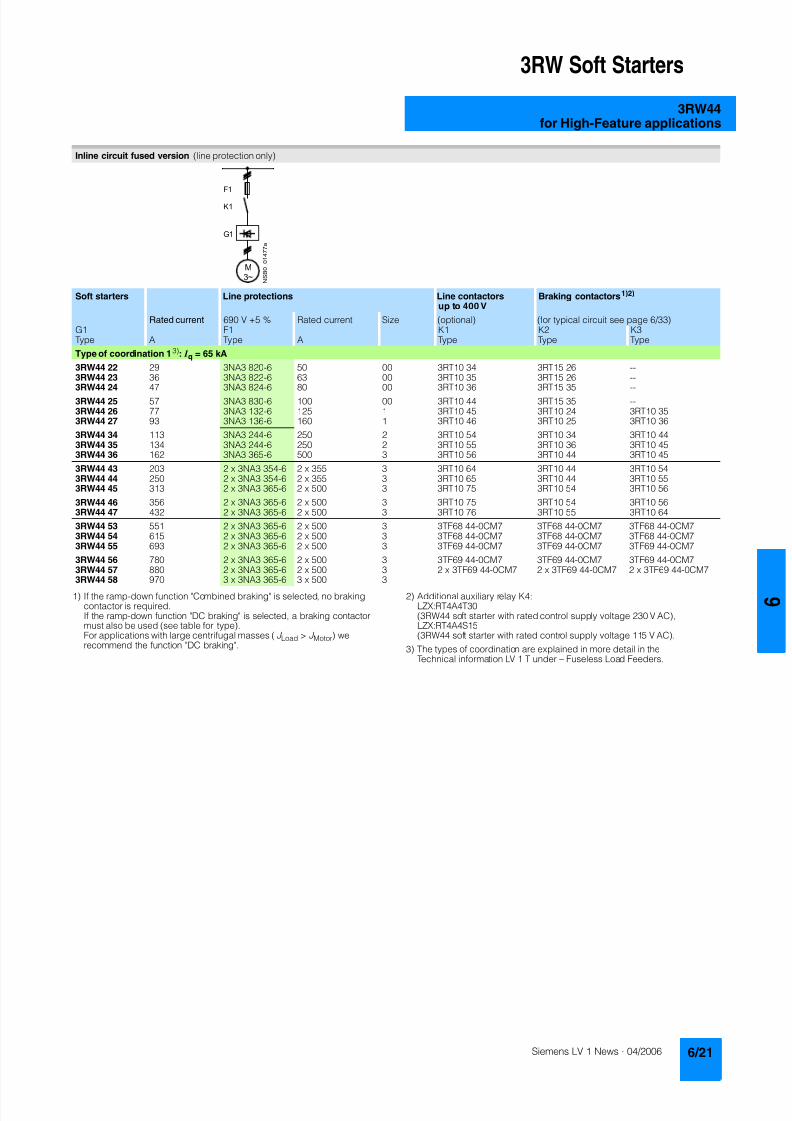
8122019 Arr Estado Solido
httpslidepdfcomreaderfullarr-estado-solido 2540
3RW Soft Starters
3RW44for High-Feature applications
1) If the ramp-down function Combined braking is selected no brakingcontactor is requiredIf the ramp-down function DC braking is selected a braking contactormust also be used (see table for type)For applications with large centrifugal masses (J Load gt J Motor) werecommend the function DC braking
2) Additional auxiliary relay K4LZXRT4A4T30(3RW44 soft starter with rated control supply voltage 230 V AC)LZXRT4A4S15(3RW44 soft starter with rated control supply voltage 115 V AC)
3) The types of coordination are explained in more detail in theTechnical information LV 1 T under ndash Fuseless Load Feeders
Inline circuit fused version (line protection only)
Soft starters Line protections Line contactorsup to 400 V
Braking contactors1)2)
Rated current 690 V +5 Rated current Size (optional) (for typical circuit see page 633)G1 F1 K1 K2 K3Type A Type A Type Type Type
Type of coordination 13) I q = 65 kA
3RW44 22 29 3NA3 820-6 50 00 3RT10 34 3RT15 26 --3RW44 23 36 3NA3 822-6 63 00 3RT10 35 3RT15 26 --
3RW44 24 47 3NA3 824-6 80 00 3RT10 36 3RT15 35 --3RW44 25 57 3NA3 830-6 100 00 3RT10 44 3RT15 35 --3RW44 26 77 3NA3 132-6 125 1 3RT10 45 3RT10 24 3RT10 353RW44 27 93 3NA3 136-6 160 1 3RT10 46 3RT10 25 3RT10 36
3RW44 34 113 3NA3 244-6 250 2 3RT10 54 3RT10 34 3RT10 443RW44 35 134 3NA3 244-6 250 2 3RT10 55 3RT10 36 3RT10 453RW44 36 162 3NA3 365-6 500 3 3RT10 56 3RT10 44 3RT10 45
3RW44 43 203 2 x 3NA3 354-6 2 x 355 3 3RT10 64 3RT10 44 3RT10 543RW44 44 250 2 x 3NA3 354-6 2 x 355 3 3RT10 65 3RT10 44 3RT10 553RW44 45 313 2 x 3NA3 365-6 2 x 500 3 3RT10 75 3RT10 54 3RT10 56
3RW44 46 356 2 x 3NA3 365-6 2 x 500 3 3RT10 75 3RT10 54 3RT10 563RW44 47 432 2 x 3NA3 365-6 2 x 500 3 3RT10 76 3RT10 55 3RT10 64
3RW44 53 551 2 x 3NA3 365-6 2 x 500 3 3TF68 44-0CM7 3TF68 44-0CM7 3TF68 44-0CM73RW44 54 615 2 x 3NA3 365-6 2 x 500 3 3TF68 44-0CM7 3TF68 44-0CM7 3TF68 44-0CM73RW44 55 693 2 x 3NA3 365-6 2 x 500 3 3TF69 44-0CM7 3TF69 44-0CM7 3TF69 44-0CM7
3RW44 56 780 2 x 3NA3 365-6 2 x 500 3 3TF69 44-0CM7 3TF69 44-0CM7 3TF69 44-0CM73RW44 57 880 2 x 3NA3 365-6 2 x 500 3 2 x 3TF69 44-0CM7 2 x 3TF69 44-0CM7 2 x 3TF69 44-0CM7
3RW44 58 970 3 x 3NA3 365-6 3 x 500 3
8122019 Arr Estado Solido
httpslidepdfcomreaderfullarr-estado-solido 2640
3RW Soft Starters
3RW44for High-Feature applications
1) If the ramp-down function Combined braking is selected no brakingcontactor is requiredIf the ramp-down function DC braking is selected a braking contactormust also be used (see table for type)For applications with large centrifugal masses (J Load gt J Motor) werecommend the function DC braking
2) Additional auxiliary relay K4LZXRT4A4T30(3RW44 soft starter with rated control supply voltage 230 V AC)LZXRT4A4S15(3RW44 soft starter with rated control supply voltage 115 V AC)
3) The types of coordination are explained in more detail in theTechnical information LV 1 T under ndash Fuseless Load Feeders
Inline circuit fused version with 3NE1 SITOR all-range fuse (semiconductor and line protection)
Soft starters All-range fuses Line contactors upto 400 V
Braking contactors1)2)
Ratedcurrent
Rated current Voltage Size (optional) (for typical circuit see page 633)
G1 Frsquo1 K1 K2 K3Type A Type A V Type Type Type
Type of coordination 23) I q = 65 kA
3RW44 22 29 3NE1 020-2 80 690 +5 00 3RT10 34 3RT15 26 --
3RW44 23 36 3NE1 020-2 80 690 +5 00 3RT10 35 3RT15 26 --3RW44 24 47 3NE1 021-2 100 690 +5 00 3RT10 36 3RT15 35 --
3RW44 25 57 3NE1 022-2 125 690 +5 00 3RT10 44 3RT15 35 --3RW44 26 77 3NE1 022-2 125 690 +5 00 3RT10 45 3RT10 24 3RT10 353RW44 27 93 3NE1 024-2 160 690 +5 1 3RT10 46 3RT10 25 3RT10 36
3RW44 34 113 3NE1 225-2 200 690 +5 1 3RT10 54 3RT10 34 3RT10 443RW44 35 134 3NE1 227-2 250 690 +5 1 3RT10 55 3RT10 36 3RT10 453RW44 36 162 3NE1 227-2 250 690 +5 1 3RT10 56 3RT10 44 3RT10 45
3RW44 43 203 3NE1 230-2 315 600 +10 1 3RT10 64 3RT10 44 3RT10 543RW44 44 250 3NE1 331-2 350 460 +10 2 3RT10 65 3RT10 44 3RT10 553RW44 45 313 3NE1 333-2 450 690 +5 2 3RT10 75 3RT10 54 3RT10 56
3RW44 46 356 3NE1 334-2 500 690 +5 2 3RT10 75 3RT10 54 3RT10 563RW44 47 432 3NE1 435-2 560 690 +5 3 3RT10 76 3RT10 55 3RT10 64
3RW44 53 551 2 x 3NE1 334-2 500 690 +10 2 3TF68 44-0CM7 3TF68 44-0CM7 3TF68 44-0CM73RW44 54 615 2 x 3NE1 334-2 500 690 +10 2 3TF68 44-0CM7 3TF68 44-0CM7 3TF68 44-0CM73RW44 55 693 2 x 3NE1 334-2 500 690 +10 2 3TF69 44-0CM7 3TF69 44-0CM7 3TF69 44-0CM7
3RW44 56 780 2 x 3NE1 435-2 560 690 +10 3 3TF69 44-0CM7 3TF69 44-0CM7 3TF69 44-0CM7
3RW44 57 880 2 x 3NE1 435-2 560 690 +10 3 2 x 3TF69 44-0CM7 2 x 3TF69 44-0CM7 2 x 3TF69 44-0CM73RW44 58 970 2 x 3NE1 435-2 560 690 +10 3
8122019 Arr Estado Solido
httpslidepdfcomreaderfullarr-estado-solido 2740
3RW Soft Starters
3RW44for High-Feature applications
1) If the ramp-down function Combined braking is selected no brakingcontactor is requiredIf the ramp-down function DC braking is selected a braking contactor
must also be used (see table for type)For applications with large centrifugal masses (J Load gt J Motor) werecommend the function DC braking
2) Additional auxiliary relay K4LZXRT4A4T30(3RW44 soft starter with rated control supply voltage 230 V AC)
LZXRT4A4S15(3RW44 soft starter with rated control supply voltage 115 V AC)
3) The types of coordination are explained in more detail in theTechnical information LV 1 T under ndash Fuseless Load Feeders
Inline circuit fused version with 3NE or 3NC SITOR semiconductor fuse(semiconductor protection by fuse lead and overload protection by circuit-breaker)
Soft starters Semiconductor fuses minimum Semiconductor fuses maximum Semiconductor fuses (cylinder)
Ratedcurrent
Rated current Size Rated current Size Rated current Size
G1 F3 F3 F3Type A Type A Type A Type A
Type of coordination 23) I q = 65 kA
3RW44 22 29 3NE4 120 80 0 3NE4 121 100 0 3NC2 280 80 22 x 58
3RW44 23 36 3NE4 121 100 0 3NE4 122 125 0 3NC2 200 100 22 x 583RW44 24 47 3NE4 121 100 0 3NE4 122 125 0 3NC2 200 100 22 x 58
3RW44 25 57 3NE4 122 125 0 3NE4 124 160 03RW44 26 77 3NE4 124 160 0 3NE4 124 160 03RW44 27 93 3NE3 224 160 1 3NE3 333 450 2
3RW44 34 113 3NE3 225 200 1 3NE3 335 560 23RW44 35 134 3NE3 225 200 1 3NE3 335 560 23RW44 36 162 3NE3 227 250 1 3NE3 333 450 2
3RW44 43 203 3NE3 230-0B 315 1 3NE3 333 450 23RW44 44 250 3NE3 230-0B 315 1 3NE3 333 450 23RW44 45 313 3NE3 233 450 1 3NE3 336 630 2
3RW44 46 356 3NE3 333 450 2 3NE3 336 630 23RW44 47 432 3NE3 335 560 2 3NE3 338-8 800 2
3RW44 53 551 2 x 3NE3 335 560 2 3 x 3NE3 334-0B 500 23RW44 54 615 2 x 3NE3 335 560 2 3 x 3NE3 334-0B 500 23RW44 55 693 2 x 3NE3 335 560 2 3 x 3NE3 334-0B 500 2
3RW44 56 780 2 x 3NE3 336 630 2 2 x 3NE3 340-8 900 2
3RW44 57 880 2 x 3NE3 336 630 2 2 x 3NE3 340-8 900 23RW44 58 970 2 x 3NE3 336 630 2 2 x 3NE3 340-8 900 2
Soft starters Line contactorsup to 400 V
Braking contactors1)2) Motor starter protectors circuit-breakers
Max line protection
Ratedcurrent
(optional) (for typical circuit see page 633) 440 V +10 Rated current 690 V +5 Rated current Size
G1 K1 Q1 F1Type A Type Type Type Type A Type A
Type of coordination 23) 3RW44 22 3RW44 27 I q = 32 kA 3RW44 34 and 3RW44 35 I q = 16 kA 3RW44 36 3RW44 57 I q = 65 kA
3RW44 22 29 3RT10 34 3RT15 26 -- 3RV10 41-4HA10 50 3NA3 820-6 50 003RW44 23 36 3RT10 35 3RT15 26 -- 3RV10 41-4JA10 63 3NA3 822-6 63 003RW44 24 47 3RT10 36 3RT15 35 -- 3RV10 41-4KA10 75 3NA3 824-6 80 00
3RW44 25 57 3RT10 44 3RT15 35 -- 3RV10 41-4LA10 90 3NA3 830-6 100 003RW44 26 77 3RT10 45 3RT10 24 3RT10 35 3RV10 41-4MA10 100 3NA3 132-6 125 13RW44 27 93 3RT10 46 3RT10 25 3RT10 36 3RV10 41-4MA10 100 3NA3 136-6 160 1
3RW44 34 113 3RT10 54 3RT10 34 3RT10 44 3VL17 16-1DD36 160 3NA3 244-6 250 2
3RW44 35 134 3RT10 55 3RT10 36 3RT10 45 3VL17 16-1DD36 160 3NA3 244-6 250 23RW44 36 162 3RT10 56 3RT10 44 3RT10 45 3VL37 25-1DC36 250 3NA3 365-6 500 3
3RW44 43 203 3RT10 64 3RT10 44 3RT10 54 3VL47 31-1DC36 315 2 x 3NA3 354-6 2 x 355 33RW44 44 250 3RT10 65 3RT10 44 3RT10 55 3VL47 31-1DC36 315 2 x 3NA3 354-6 2 x 355 33RW44 45 313 3RT10 75 3RT10 54 3RT10 56 3VL47 40-1DC36 400 2 x 3NA3 365-6 2 x 500 3
3RW44 46 356 3RT10 75 3RT10 54 3RT10 56 3VL47 40-1DC36 400 2 x 3NA3 365-6 2 x 500 33RW44 47 432 3RT10 76 3RT10 55 3RT10 64 3VL57 50-1DC36 500 2 x 3NA3 365-6 2 x 500 3
3RW44 53 551 3TF68 44-0CM7 3TF68 44-0CM7 3TF68 44-0CM7 3VL67 80-1AB36 800 2 x 3NA3 365-6 2 x 500 33RW44 54 615 3TF68 44-0CM7 3TF68 44-0CM7 3TF68 44-0CM7 3VL67 80-1AB36 800 2 x 3NA3 365-6 2 x 500 33RW44 55 693 3TF69 44-0CM7 3TF69 44-0CM7 3TF69 44-0CM7 3VL67 80-1AB36 800 2 x 3NA3 365-6 2 x 500 3
3RW44 56 780 3TF69 44-0CM7 3TF69 44-0CM7 3TF69 44-0CM7 3VL77 10-1AB36 1000 2 x 3NA3 365-6 2 x 500 33RW44 57 880 2 x
3TF69 44-0CM72 x3TF69 44-0CM7
2 x3TF69 44-0CM7
3VL77 10-1AB36 1000 2 x 3NA3 365-6 2 x 500 3
3RW44 58 970 3VL77 12-1AB36 1200 3 x 3NA3 365-6 3 x 500 3
8122019 Arr Estado Solido
httpslidepdfcomreaderfullarr-estado-solido 2840
3RW Soft Starters
3RW44for High-Feature applications
1) The types of coordination are explained in more detail in theTechnical information LV 1 T under ndash Fuseless Load FeedersThe type of coordination 2 only refers to soft starters not to feeder compo-nents ( I q = 65 kA)
Inside-delta circuit fused version with 3NE or 3NC SITOR fuses(semiconductor protection by fuse lead and overload protection by circuit-breaker)
Soft starters Semiconductor fuses minimum Semiconductor fuses maximum Semiconductor fuses (cylinder)
Ratedcurrent
Rated current Size Rated current Size Rated current Size
G1 F3 F3 F3Type A Type A Type A Type A
Type of coordination 21)
3RW44 22 50 3NE4 120 80 0 3NE4 121 100 0 3NC2 280 80 22 x 58
3RW44 23 62 3NE4 121 100 0 3NE4 122 125 0 3NC2 200 100 22 x 583RW44 24 81 3NE4 121 100 0 3NE4 122 125 0 3NC2 200 100 22 x 58
3RW44 25 99 3NE4 122 125 0 3NE4 124 160 03RW44 26 133 3NE4 124 160 0 3NE4 124 160 03RW44 27 161 3NE3 224 160 1 3NE3 333 450 2
3RW44 34 196 3NE3 225 200 1 3NE3 335 560 23RW44 35 232 3NE3 225 200 1 3NE3 335 560 23RW44 36 281 3NE3 227 250 1 3NE3 333 450 2
3RW44 43 352 3NE3 230-0B 315 1 3NE3 333 450 23RW44 44 433 3NE3 230-0B 315 1 3NE3 333 450 23RW44 45 542 3NE3 233 450 1 3NE3 336 630 2
3RW44 46 617 3NE3 333 450 2 3NE3 336 630 23RW44 47 748 3NE3 335 560 2 3NE3 338-8 800 2
3RW44 53 954 2 x 3NE3 335 560 2 3 x 3NE3 334-0B 500 23RW44 54 1065 2 x 3NE3 335 560 2 3 x 3NE3 334-0B 500 23RW44 55 1200 2 x 3NE3 335 560 2 3 x 3NE3 334-0B 500 2
3RW44 56 1351 2 x 3NE3 336 630 2 2 x 3NE3 340-8 900 2
3RW44 57 1524 2 x 3NE3 336 630 2 3 x 3NE3 340-8 900 23RW44 58 1680 2 x 3NE3 336 630 2 3 x 3NE3 340-8 900 2
Soft starters Line contactorsup to 400 V
Motor starter protectors cirduit-breakers
Line protections
Ratedcurrent
(optional) 440 V +10 Rated current 690 V +5 Rated current Size
G1 K1 Q1 F1Type A Type Type A Type A
Type of coordination 21)
3RW44 22 50 3RT10 36-1AP04 3RV10 4-4KA10 75 3NA3 824-6 80 003RW44 23 62 3RT10 44-1AP04 3RV10 4-4LA10 90 3NA3 830-6 100 003RW44 24 81 3RT10 46-1AP04 3RV10 4-4MA10 100 3NA3 132-6 125 1
3RW44 25 99 3RT10 54-1AP36 3VL27 16-DC36 160 3NA3 136-6 160 13RW44 26 133 3RT10 55-6AP36 3VL27 16-DC36 160 3NA3 240-6 200 23RW44 27 161 3RT10 56-6AP36 3VL37 20-DC36 200 3NA3 244-6 250 2
3RW44 34 196 3RT10 64-6AP36 3VL37 25-DC36 250 3NA3 360-6 400 3
3RW44 35 232 3RT10 65-6AP36 3VL47 31-DC36 315 3NA3 360-6 400 33RW44 36 281 3RT10 66-6AP36 3VL47 40-DC36 400 2 x 3NA3 360-6 2 x 400 3
3RW44 43 352 3RT10 75-6AP36 3VL47 40-DC36 400 2 x 3NA3 365-6 2 x 500 33RW44 44 433 3RT10 76-6AP36 3VL57 50-DC36 500 2 x 3NA3 365-6 2 x 500 33RW44 45 542 3TF68 44-0CM7 3VL57 63-DC36 800 3 x 3NA3 365-6 3 x 500 3
3RW44 46 617 3TF68 44-0CM7 3VL67 80-AB36 800 3 x 3NA3 365-6 3 x 500 33RW44 47 748 3TF69 3VL67 80-AB36 1000 3 x 3NA3 365-6 3 x 500 3
3RW44 53 954 2 x 3TF68 44-0CM7 3VL77 10-AB36 1000 3 x 3NA3 365-6 3 x 500 33RW44 54 1065 2 x 3TF68 44-0CM7 3VL77 12-AB36 1250 3 x 3NA3 365-6 3 x 500 33RW44 55 1200 2 x 3TF69 44-0CM7 3VL87 16-AB36 1600 3 x 3NA3 365-6 3 x 500 3
3RW44 56 1351 2 x 3TF69 44-0CM7 3VL87 16-AB36 1600 3 x 3NA3 372 3 x 630 33RW44 57 1524 2 x 3TF69 44-0CM7 3VL87 16-AB36 1600 3 x 3NA3 372 3 x 630 33RW44 58 1680 3WL12 20 2000 2 x 3NA3 480 2 x 1000 4
8122019 Arr Estado Solido
httpslidepdfcomreaderfullarr-estado-solido 2940
3RW Soft Starters
3RW44for High-Feature applications
Characteristic curves
Motor protection tripping characteristics for 3RW44(with symmetry)
Admissible mounting height
The admissible operational voltage is reduced to 460 V with a mountingheight of more than 2000 m
Motor protection characteristics for 3RW44(with phase unbalance)
e
2 4 6 101
Class 10 Class 15 Class 20
100
101
102
103
2
4
6
2
4
6
2
4
6
Class 5 Class 30
N S B 0
_ 0 1 5 0 0 a
[ s ]
x
T r i p p i n g t i m e
85
105
70
75
80
90
95
100
N S B 0
_ 0 1 7 0 4
0 1000 2000 3000 4000 5000 O p e r
a t i o n a
l r a
t e d c u r r e n
t I
i n
Mounting height in m
e
e
1001
Class 10 Class 15 Class 20
100
101
102
103
2
4
6
2
4
6
2
4
6
Class 5 Class 30
N S B 0
_ 0 1 7 0 6
[ s ]
x10
T r i p p
i n g
t i m e
8122019 Arr Estado Solido
httpslidepdfcomreaderfullarr-estado-solido 3040
3RW Soft Starters
3RW44for High-Feature applications
More information
Application examples for normal starting (Class 10)
Application examples for heavy starting (Class 20)
Application examples for very heavy starting (Class 30)
NoteThese tables present sample setting values and device sizesThey are intended only for the purposes of information and arenot binding The setting values depend on the application inquestion and must be optimized during commissioningThe soft starter dimensions should be checked where necessarywith the Win-Soft Starter software or with the help ofTechnical Assistance
Normal starting Class 10 (up to 20 s with 350 I n motor)The soft starter rating can be selected to be as high as the rating of the motor used
Application Conveyor belts Roller conveyors Compressors Small ventilators Pumps Hydraulic pumps
Starting parameters
bull Voltage ramp and currentlimiting- Starting voltage 70 60 50 30 30 30- Starting time s 10 10 10 10 10 10- Current limit value Deactivated Deactivated 4 x I M 4 x I M Deactivated Deactivated
bull Torque ramp- Starting torque 60 50 40 20 10 10- End torque 150 150 150 150 150 150- Starting time 10 10 10 10 10 10
bull Breakaway pulse Deactivated (0 ms) Deactivated (0 ms) Deactivated (0 ms) Deactivated (0 ms) Deactivated (0 ms) Deactivated (0 ms)
Ramp-down mode Smoothramp-down
Smoothramp-down
Free ramp-down Free ramp-down Pump ramp-down Free ramp-down
Heavy starting Class 20 (up to 40 s with 350 I n motor)The soft starter has to be selected one rating class higher than the motor used
Application Stirrers Centrifuges Milling machines
Starting parameters
bull Voltage ramp and currentlimiting- Starting voltage 30 30 30- Starting time s 30 30 30- Current limit value 4 x I M 4 x I M 4 x I M
bull Torque ramp- Starting torque 30 30 30- End torque 150 150 150- Starting time 30 30 30
bull Breakaway pulse Deactivated (0 ms) Deactivated (0 ms) Deactivated (0 ms)
Ramp-down mode Free ramp-down Free ramp-down Free ramp-down or DC braking
Very heavy starting Class 30 (up to 60 s with 350 I n motor)The soft starter has to be selected two rating classes higher than the motor used
Application Large ventilators Mills Breakers Circular sawbandsaws
Starting parameters
bull Voltage ramp and currentlimiting- Starting voltage 30 50 50 30- Starting time s 60 60 60 60- Current limit value 4 x I M 4 x I M 4 x I M 4 x I M
bull Torque ramp- Starting torque 20 50 50 20- End torque 150 150 150 150- Starting time 60 60 60 60
bull Breakaway pulse Deactivated (0 ms) 80 300 ms 80 300 ms Deactivated (0 ms)
Ramp-down mode Free ramp-down Free ramp-down Free ramp-down Free ramp-down
8122019 Arr Estado Solido
httpslidepdfcomreaderfullarr-estado-solido 3140
3RW Soft Starters
3RW44for High-Feature applications
Circuit concept
The SIRIUS 3RW44 soft starters can be operated in two differenttypes of circuit
bull Inline circuitThe controls for isolating and protecting the motor are simplyconnected in series with the soft starter The motor isconnected to the soft starter with three leads
bull Inside-delta circuitThe wiring is similar to that of wye-delta starters The phases ofthe soft starter are connected in series with the individual motorwindings The soft starter then only has to carry the phasecurrent amounting to about 58 of the rated motor current(conductor current)
Comparison of the types of circuit
Inline circuitRated current I e corresponds to the rated motor current I n3 leads to the motor
Inside-delta circuit
Rated current I e corresponds to approx 58 of the rated motorcurrent I n6 leads to the motor (as with wye-delta starters)
Which circuit
Using the inline circuit involves the lowest wiring complexityIf the soft starter to motor connections are long this contactsequence is preferableWith the inside-delta circuit there is double the wiring complexitybut a smaller size of device can be used at the same rating
Thanks to choosing the operational mode between the inline cir-cuit and inside-delta circuit the most favorable solution can al-ways be chosen
The braking function is possible only in the inline circuit
Configuration
The 3RW44 solid-state soft starters are designed for normalstarting In case of heavy starting or increased starting
frequency a larger device must be selectedFor long starting times it is recommended to have a PTC ther-mistor detector in the motor This also applies for the ramp-downmodes smooth ramp-down pump ramp-down and DC brakingbecause during the ramp-down time in these modes an addi-tional current loading applies in contrast to free ramp-down
In the motor feeder between the SIRIUS 3RW soft starter and themotor no capacitive elements are permitted (eg no reactive-power compensation equipment) In addition neither staticsystems for reactive-power compensation nor dynamic PFC(Power Factor Correction) must be operated in parallel duringstarting and ramp-down of the soft starter This is important toprevent faults arising on the compensation equipment andor thesoft starter
All elements of the main circuit (such as fuses and controls)
should be dimensioned for direct starting following the localshort-circuit conditions Fuses switching devices and overloadrelays must be ordered separately
The harmonic component load for starting currents must betaken into consideration for the selection of motor starterprotectors (selection of release)
NoteWhen switching on three-phase current motors voltage dropsnormally will occur with all types of starters (direct starters star- delta starters soft starters) On principle the feeding transformermust be configured such that when starting the motor thevoltage drop must occur within the admissible tolerance Whenthe feeding transformer is designed quite scarce the control vol- tage (being independent of the main voltage) should be sup- plied with a separate circuit in order to prevent the soft starterfrom switching off
Serial PC interface PROFIBUS DP communication moduleand parameterizing and operating software Soft Starter ES
The solid-state 3RW44 soft starters have a PC interface forcommunicating with the Soft Starter ES 2006 Smart software orto be connected to an external operating and monitoring mod-ule When using the optional communication module PROFIBUSthe 3RW44 soft starter can be connected to the PROFIBUS netand can communicate via GSD file or software Soft Starter ES2006 Professional
Manual for SIRIUS 3RW44
Besides containing all important information on planning com-missioning and servicing the manual also contains suggestedcircuits and the technical specifications for all devices
Win-Soft Starter selection and simulation program
With this software you can simulate and select all Siemens softstarters taking into account various parameters such as mainsproperties motor and load data and special applicationrequirements
The software is a valuable tool which makes complicatedlengthy manual calculations for determining the required softstarters superfluous
You can order the CD-ROM under the following order numberOrder No E20001-D1020-P302-V2-7400
More information can be found on the Internet athttpwwwsiemenscomsoftstarter
8122019 Arr Estado Solido
httpslidepdfcomreaderfullarr-estado-solido 3240
3RW Soft Starters
3RW44for High-Feature applications
SIRIUS soft starter training course (SD-SIRIUSO)
Siemens offers a 2-day training course on the SIRIUS solid-statesoft starters to keep customers and own personnel up-to-date on
configuring commissioning and servicing issuesPlease direct enquiries and applications to
AampD PT 4 (Trainings-Center Erlangen)Werner-von-Siemens-Str 65D-91052 ErlangenTelefon ++49 9131 729262Telefax ++49 9131 728172sibrainindustrysiemenscomhttp wwwsiemenscomsitrain
8122019 Arr Estado Solido
httpslidepdfcomreaderfullarr-estado-solido 3340
3RW Soft Starters
Project planning aids
Dimensional drawings
3RW44 2 3RW44 3 and 3RW44 4 for High-Feature applications
TypeDimension(mm)
a b c d e f g h I k l m n o p q
3RW44 2 180 170 37 11 167 100 240 270 180 148 75 153 7 184 66 M6 10 Nm
3RW44 3 180 170 37 17 167 100 240 270 180 148 75 153 7 198 9 M6 10 Nm
3RW44 4 210 210 48 25 190 140 269 298 205 166 16 166 9 230 11 M8 15 Nm
8122019 Arr Estado Solido
httpslidepdfcomreaderfullarr-estado-solido 3440
3RW Soft Starters
Project planning aids
3RW44 5 for High-Feature applications
147
173
195
118
N S B 0_
0 1 6 5 3
261
290
249
162
152
6 2 3
1 0 5
2 5 3
1 6 5
76
44
470
510
1
5 5
2
0Oslash14 40
6 3 8 5
5 9 0
8122019 Arr Estado Solido
httpslidepdfcomreaderfullarr-estado-solido 3540
3RW Soft Starters
Project planning aids
Schematics
1) Permissible values for main and control voltagesee Technical Specifications
3RW44 connection examples for main and control circuits
Main circuit Control circuitPossibility 1a Possibility 1Inline circuit with circuit-breaker and SITOR fuse(semiconductor protection only)
Control by pushbutton
Main circuit
Possibility 1b Possibility 1cInline circuit with full-rangeprotection (line andsemiconductor protection)
Inline circuit with line andSITOR fuse(semiconductor protection only)
Q1
L3L2L1
G1
F3
T1 T2 T3
M1
N S B 0_
0 1 4 9 0 a
L1 L2 L3
V1U1 W1
MPE 3~
3NPE 400 V AC 50 Hz
(optionalsemiconductorprotection fuse)
13 14 23 24 33 34 95 9896 +
T1 T2IN4IN3IN2IN1L-L+A1
A2
NPE
PE
G1
F2
NSB0_01494a
S t a r t
S 2
R e s e t S
3
StopS1
L1
On periodGrouperror
N o a c t i o n
N o a c t i o n
Noaction
PTC type Aor
Thermoclick
Noaction
1NPE 230 V AC 50 Hz
M o t o r o
n r i g h t
P S
1
1)
8122019 Arr Estado Solido
httpslidepdfcomreaderfullarr-estado-solido 3640
3RW Soft Starters
Project planning aids
1) Permissible values for main and control voltagesee Technical Specifications
2) Caution Risk of restartingThe start command (eg from the PLC) must be reset prior to a resetcommand because a new automatic restart will take place automaticallyif a start command is active after the reset command This appliesespecially in case of motor protection trippingFor safety reasons we recommend incorporating the group error output(terminals 95 and 96) in the controller
Main circuit Control circuit
Possibility 2 Possibility 2Inline circuit with main contactor Control of a main contactor and control by means of PLC
Q1
L3L2L1
G1
K1
F3
L1 L2 L3
T1 T2 T3
M1
N S B 0_
0 1 4 9 5 a
V1U1 W1
MPE 3~
1)
(optionalsemiconductorprotection)
(optional linecontactor if floatingswitching of themotor is planned)
3NPE 400 V AC 50 Hz
13 14 23 24 33 34 95 9896+
T1 T2IN4IN3IN2IN1L-L+A1
A2
NPE
PE
G1
K1NSB0_01496a
F2+24 V DC
M
L1 1NPE AC 230 V 50 Hz1)
Switch-on duration
M o t o r r i g h t
T r i p R e s e t
PLC outputs PLC inputs
N o a c t i o n
N o a c t i o n
No action No action
Group error
PTC type A Thermoclick
(optional line contactorif floating switchingof the motor is planned)
P S 1
ResetStart 2)
8122019 Arr Estado Solido
httpslidepdfcomreaderfullarr-estado-solido 3740
3RW Soft Starters
Project planning aids
1) Permissible values for main and control voltagesee Technical Specifications
2) Caution Risk of restartingThe start command (eg from the PLC) must be reset prior to a resetcommand because a new automatic restart will take place automaticallyif a start command is active after the reset command This applies espe-cially in case of motor protection trippingFor safety reasons we recommend incorporating the group error output(terminals 95 and 96) in the controller
3) If the ramp-down function Combined braking is selected no brakingcontactor is requiredIf the ramp-down function DC braking is selected a braking contactormust be used in addition Type see Fuse Coordination (inline circuit) onpages 621 to 623For applications with large centrifugal masses (J Load gt J Motor) werecommend the function DC brakingThe output 2 must be switched over to DC braking contactor
4) Auxiliary relay K4 egLZXRT4A4T30 (230 V AC rated control supply voltage)LZXRT4A4S15 (115 V AC rated control supply voltage)
Main circuit Control circuit
Possibility 3a Possibility 3aInline circuit with ramp-down function DC braking3)
(for device types 3RW44 22 to 3RW44 25)Control of the braking contactor3)
Main circuit Control circuit
Possibility 3b Possibility 3bInline circuit with ramp-down function DC braking3)
(for device types 3RW44 26 to 3RW44 47)Control of the braking contactor3)
Q1
L3L2
G1
F3
T1 T2 T3
M1
N S B 0_
0 1 5 0 1 a
L1 L2 L3
V1U1 W1
M
K2 K2 K2
PE 3~
1)
2
(optionalsemi-conductorprotection)
L1 3NPE 400 V AC 50 Hz
13 14 23 24 33 34 95 9896 +
T1 T2IN4IN3IN2IN1L-L+A1
A2
NPE
PEG1
K2NSB0_01502
R e s e t
M Start Reset
+24 V DC
K2
F2
1)
2)
No action Group error
N o a c t i o n
N o a c t i o n
On period
PLC output
PTC type Aor
Thermoclick
L1 1NPE 230 V AC 50 Hz
DC braking contactor 3)
K2 K33 3
G1
F3
T1 T2 T3
M1
N S B 0_
0 1
5 0 3 a
L1 L2 L3
V1U1 W1
MPE 3~
Q1
L3L2
1)
(optionalsemi-conductorprotection)
L1 3NPE 400 V AC 50 Hz
13 14 23 24 33 34 95 9896 +
T1 T2IN4IN3IN2IN1L-L+A1
A2
NPE
PE
G1
K4
NSB0_01504
R e s e t
K4 K4
K3 K2
K2 K3
+24 V DC
M Start Reset
F2
1)
2)
4)
PLC output
No action Group error
N o a c t i o n
N o a c t i o n
ON period
PTC type Aor
Thermoclick
M o t o r o n r i g h t
L1 1NPE 230 V AC 50 Hz
DC braking contactor 3)
8122019 Arr Estado Solido
httpslidepdfcomreaderfullarr-estado-solido 3840
3RW Soft Starters
Notes
1) Permissible values for main and control voltagesee Technical Specifications
2) Caution Risk of restartingThe start command (eg from the PLC) must be reset prior to a resetcommand because a new automatic restart will take place automaticallyif a start command is active after the reset command This appliesespecially in case of motor protection trippingFor safety reasons we recommend incorporating the group error output(terminals 95 and 96) in the controller
Main circuit Control circuit
Possibility 4a Possibility 4b Possibility 4Inside-delta circuit Change of direction of rotation for
inside-delta circuitControl by means of PLC
13 14 23 24 33 34 95 9896+
T1 T2IN4IN3IN2IN1L-L+A1
A2
NPE
PEG1
NSB0_01498a
+24 V DC
M
F2
L1 1NPE AC 230 V 50 Hz1)
2)
R e s e t
Switch-onduration
No action
Group error
N o a c t i o n
N o a c t i o n
No action
PTC type A orThermoclick
M o t o r r i g h t
PLC outputs PLC inputs
Start Reset
7
8122019 Arr Estado Solido
httpslidepdfcomreaderfullarr-estado-solido 3940
Appendix
Conditions of sale and delivery
Terms and Conditions of Sale and Delivery
By using this catalog you can acquire hardware and softwareproducts described therein from the Siemens AG subject to the
following terms Please note The scope the quality and the con-ditions for supplies and services including software productsby any Siemens entity having a registered office outside of Ger-many shall be subject exclusively to the General Terms andConditions of the respective Siemens entity
For customers with a seat or registered office in theFederal Republic of Germany
The bdquoGeneral Terms of Paymentldquo as well as the bdquoGeneral Condi-tions for the Supply of Products and Services of the Electricaland Electronics Industryldquo shall apply
For software products the bdquoGeneral License Conditions for Soft-ware Products for Automation and Drives for Customers with aSeat or registered Office in Germanyldquo shall apply
For customers with a seat or registered office outside of
Germany The bdquoGeneral Terms of Paymentldquo as well as the bdquoGeneral Condi-tions for Supplies of Siemens Automation and Drives for Cus-tomers with a Seat or registered Office outside of Germanyldquo shallapply
For software products the bdquoGeneral License Conditions for Soft-ware Products for Automation and Drives for Customers with aSeat or registered Office outside of Germanyldquo shall apply
General
The prices are in 991404 (Euro) ex works exclusive packaging
The sales tax (value added tax) is not included in the pricesIt shall be debited separately at the respective rate according tothe applicable legal regulations
In addition to the prices of products which include silver plump
aluminum andor copper surcharges may be calculated if therespective limits of the notes are exceeded The respective note(eg source German newspaper bdquoHandesblattldquo in categorybdquodeutsche Edelmetalleldquo and bdquoMetallverarbeiterldquo) for silver (bdquover-arbeitetes Silberldquo) plump (bdquoBlei in Kabelnldquo) aluminum (bdquoAlumin-ium in Kabelnldquo) and copper (bdquoElektrolytkupferldquo bdquoDEL-Notizldquo) re-spectively of the day the order or rather the on call order isreceived is decisive for the calculation of the surcharges
Surcharges of copper shall be calculated for Drives at a note(bdquoDEL-Notizldquo) above EUR 22500 100 Kg and for chokes trans-formers above EUR 15000 100 kg
Surcharges shall be charged based on the quantities of the ma-terials which are contained in the relevant products
Prices are subject to change without prior notice We will debitthe prices valid at the time of delivery
The dimensions are in mm In Germany according to the Ger-man law on units in measuring technology data in inches onlyapply to devices for export
Illustrations are not binding
Insofar as there are no remarks on the corresponding pages- especially with regard to data dimensions and weights given -these are subject to change without prior notice
Comprehensive Terms and Conditions of Sale and Delivery areavailable free of charge from your local Siemens business officeunder the following Order Nos
bull 6ZB5310-0KR30-0BA0(for customers based in the Federal Republic of Germany)
bull 6ZB5310-0KS53-0BA0(for customers based outside of theFederal Republic ofGermany)
or download them from the Internethttpwwwsiemenscomautomationmall (Germany AampD Mall Online-Help System)
Export regulations
The products listed in this catalog price list may be subject toEuropean German andor US export regulations
Therefore any export requiring a license is subject to approvalby the competent authorities
According to current provisions the following export regulations
must be observed with respect to the products featured in thiscatalog price list
Even without a label or with an ldquoAL Nldquo or ldquoECCN Nldquo authoriza-tion may be required due to the final destination and purpose forwhich the goods are to be used
The deciding factors are the AL or ECCN export authorizationindicated on order confirmations delivery notes and invoices
Errors excepted and subject to change without prior notice
AampDVuLEn 060306
AL Number of the German Export List
Products marked other than ldquoNldquo require an exportlicenseIn the case of software products the export des-ignations of the relevant data medium must alsobe generally adhered to
Goods labeled with an ldquoAL not equal to Nldquo aresubject to a European or German export authori-zation when being exported out of the EU
ECCN Export Control Classification Number
Products marked other than ldquoNldquo are subject to a
reexport license to specific countriesIn the case of software products the exportdesignations of the relevant data medium mustalso be generally adhered to
Goods labeled with an ldquoECCN not equal to Nldquo aresubject to a US re-export authorization
_ _ _ _
8122019 Arr Estado Solido
httpslidepdfcomreaderfullarr-estado-solido 4040
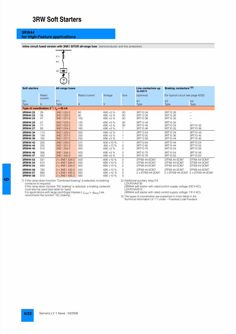
8122019 Arr Estado Solido
httpslidepdfcomreaderfullarr-estado-solido 2640
3RW Soft Starters
3RW44for High-Feature applications
1) If the ramp-down function Combined braking is selected no brakingcontactor is requiredIf the ramp-down function DC braking is selected a braking contactormust also be used (see table for type)For applications with large centrifugal masses (J Load gt J Motor) werecommend the function DC braking
2) Additional auxiliary relay K4LZXRT4A4T30(3RW44 soft starter with rated control supply voltage 230 V AC)LZXRT4A4S15(3RW44 soft starter with rated control supply voltage 115 V AC)
3) The types of coordination are explained in more detail in theTechnical information LV 1 T under ndash Fuseless Load Feeders
Inline circuit fused version with 3NE1 SITOR all-range fuse (semiconductor and line protection)
Soft starters All-range fuses Line contactors upto 400 V
Braking contactors1)2)
Ratedcurrent
Rated current Voltage Size (optional) (for typical circuit see page 633)
G1 Frsquo1 K1 K2 K3Type A Type A V Type Type Type
Type of coordination 23) I q = 65 kA
3RW44 22 29 3NE1 020-2 80 690 +5 00 3RT10 34 3RT15 26 --
3RW44 23 36 3NE1 020-2 80 690 +5 00 3RT10 35 3RT15 26 --3RW44 24 47 3NE1 021-2 100 690 +5 00 3RT10 36 3RT15 35 --
3RW44 25 57 3NE1 022-2 125 690 +5 00 3RT10 44 3RT15 35 --3RW44 26 77 3NE1 022-2 125 690 +5 00 3RT10 45 3RT10 24 3RT10 353RW44 27 93 3NE1 024-2 160 690 +5 1 3RT10 46 3RT10 25 3RT10 36
3RW44 34 113 3NE1 225-2 200 690 +5 1 3RT10 54 3RT10 34 3RT10 443RW44 35 134 3NE1 227-2 250 690 +5 1 3RT10 55 3RT10 36 3RT10 453RW44 36 162 3NE1 227-2 250 690 +5 1 3RT10 56 3RT10 44 3RT10 45
3RW44 43 203 3NE1 230-2 315 600 +10 1 3RT10 64 3RT10 44 3RT10 543RW44 44 250 3NE1 331-2 350 460 +10 2 3RT10 65 3RT10 44 3RT10 553RW44 45 313 3NE1 333-2 450 690 +5 2 3RT10 75 3RT10 54 3RT10 56
3RW44 46 356 3NE1 334-2 500 690 +5 2 3RT10 75 3RT10 54 3RT10 563RW44 47 432 3NE1 435-2 560 690 +5 3 3RT10 76 3RT10 55 3RT10 64
3RW44 53 551 2 x 3NE1 334-2 500 690 +10 2 3TF68 44-0CM7 3TF68 44-0CM7 3TF68 44-0CM73RW44 54 615 2 x 3NE1 334-2 500 690 +10 2 3TF68 44-0CM7 3TF68 44-0CM7 3TF68 44-0CM73RW44 55 693 2 x 3NE1 334-2 500 690 +10 2 3TF69 44-0CM7 3TF69 44-0CM7 3TF69 44-0CM7
3RW44 56 780 2 x 3NE1 435-2 560 690 +10 3 3TF69 44-0CM7 3TF69 44-0CM7 3TF69 44-0CM7
3RW44 57 880 2 x 3NE1 435-2 560 690 +10 3 2 x 3TF69 44-0CM7 2 x 3TF69 44-0CM7 2 x 3TF69 44-0CM73RW44 58 970 2 x 3NE1 435-2 560 690 +10 3
8122019 Arr Estado Solido
httpslidepdfcomreaderfullarr-estado-solido 2740
3RW Soft Starters
3RW44for High-Feature applications
1) If the ramp-down function Combined braking is selected no brakingcontactor is requiredIf the ramp-down function DC braking is selected a braking contactor
must also be used (see table for type)For applications with large centrifugal masses (J Load gt J Motor) werecommend the function DC braking
2) Additional auxiliary relay K4LZXRT4A4T30(3RW44 soft starter with rated control supply voltage 230 V AC)
LZXRT4A4S15(3RW44 soft starter with rated control supply voltage 115 V AC)
3) The types of coordination are explained in more detail in theTechnical information LV 1 T under ndash Fuseless Load Feeders
Inline circuit fused version with 3NE or 3NC SITOR semiconductor fuse(semiconductor protection by fuse lead and overload protection by circuit-breaker)
Soft starters Semiconductor fuses minimum Semiconductor fuses maximum Semiconductor fuses (cylinder)
Ratedcurrent
Rated current Size Rated current Size Rated current Size
G1 F3 F3 F3Type A Type A Type A Type A
Type of coordination 23) I q = 65 kA
3RW44 22 29 3NE4 120 80 0 3NE4 121 100 0 3NC2 280 80 22 x 58
3RW44 23 36 3NE4 121 100 0 3NE4 122 125 0 3NC2 200 100 22 x 583RW44 24 47 3NE4 121 100 0 3NE4 122 125 0 3NC2 200 100 22 x 58
3RW44 25 57 3NE4 122 125 0 3NE4 124 160 03RW44 26 77 3NE4 124 160 0 3NE4 124 160 03RW44 27 93 3NE3 224 160 1 3NE3 333 450 2
3RW44 34 113 3NE3 225 200 1 3NE3 335 560 23RW44 35 134 3NE3 225 200 1 3NE3 335 560 23RW44 36 162 3NE3 227 250 1 3NE3 333 450 2
3RW44 43 203 3NE3 230-0B 315 1 3NE3 333 450 23RW44 44 250 3NE3 230-0B 315 1 3NE3 333 450 23RW44 45 313 3NE3 233 450 1 3NE3 336 630 2
3RW44 46 356 3NE3 333 450 2 3NE3 336 630 23RW44 47 432 3NE3 335 560 2 3NE3 338-8 800 2
3RW44 53 551 2 x 3NE3 335 560 2 3 x 3NE3 334-0B 500 23RW44 54 615 2 x 3NE3 335 560 2 3 x 3NE3 334-0B 500 23RW44 55 693 2 x 3NE3 335 560 2 3 x 3NE3 334-0B 500 2
3RW44 56 780 2 x 3NE3 336 630 2 2 x 3NE3 340-8 900 2
3RW44 57 880 2 x 3NE3 336 630 2 2 x 3NE3 340-8 900 23RW44 58 970 2 x 3NE3 336 630 2 2 x 3NE3 340-8 900 2
Soft starters Line contactorsup to 400 V
Braking contactors1)2) Motor starter protectors circuit-breakers
Max line protection
Ratedcurrent
(optional) (for typical circuit see page 633) 440 V +10 Rated current 690 V +5 Rated current Size
G1 K1 Q1 F1Type A Type Type Type Type A Type A
Type of coordination 23) 3RW44 22 3RW44 27 I q = 32 kA 3RW44 34 and 3RW44 35 I q = 16 kA 3RW44 36 3RW44 57 I q = 65 kA
3RW44 22 29 3RT10 34 3RT15 26 -- 3RV10 41-4HA10 50 3NA3 820-6 50 003RW44 23 36 3RT10 35 3RT15 26 -- 3RV10 41-4JA10 63 3NA3 822-6 63 003RW44 24 47 3RT10 36 3RT15 35 -- 3RV10 41-4KA10 75 3NA3 824-6 80 00
3RW44 25 57 3RT10 44 3RT15 35 -- 3RV10 41-4LA10 90 3NA3 830-6 100 003RW44 26 77 3RT10 45 3RT10 24 3RT10 35 3RV10 41-4MA10 100 3NA3 132-6 125 13RW44 27 93 3RT10 46 3RT10 25 3RT10 36 3RV10 41-4MA10 100 3NA3 136-6 160 1
3RW44 34 113 3RT10 54 3RT10 34 3RT10 44 3VL17 16-1DD36 160 3NA3 244-6 250 2
3RW44 35 134 3RT10 55 3RT10 36 3RT10 45 3VL17 16-1DD36 160 3NA3 244-6 250 23RW44 36 162 3RT10 56 3RT10 44 3RT10 45 3VL37 25-1DC36 250 3NA3 365-6 500 3
3RW44 43 203 3RT10 64 3RT10 44 3RT10 54 3VL47 31-1DC36 315 2 x 3NA3 354-6 2 x 355 33RW44 44 250 3RT10 65 3RT10 44 3RT10 55 3VL47 31-1DC36 315 2 x 3NA3 354-6 2 x 355 33RW44 45 313 3RT10 75 3RT10 54 3RT10 56 3VL47 40-1DC36 400 2 x 3NA3 365-6 2 x 500 3
3RW44 46 356 3RT10 75 3RT10 54 3RT10 56 3VL47 40-1DC36 400 2 x 3NA3 365-6 2 x 500 33RW44 47 432 3RT10 76 3RT10 55 3RT10 64 3VL57 50-1DC36 500 2 x 3NA3 365-6 2 x 500 3
3RW44 53 551 3TF68 44-0CM7 3TF68 44-0CM7 3TF68 44-0CM7 3VL67 80-1AB36 800 2 x 3NA3 365-6 2 x 500 33RW44 54 615 3TF68 44-0CM7 3TF68 44-0CM7 3TF68 44-0CM7 3VL67 80-1AB36 800 2 x 3NA3 365-6 2 x 500 33RW44 55 693 3TF69 44-0CM7 3TF69 44-0CM7 3TF69 44-0CM7 3VL67 80-1AB36 800 2 x 3NA3 365-6 2 x 500 3
3RW44 56 780 3TF69 44-0CM7 3TF69 44-0CM7 3TF69 44-0CM7 3VL77 10-1AB36 1000 2 x 3NA3 365-6 2 x 500 33RW44 57 880 2 x
3TF69 44-0CM72 x3TF69 44-0CM7
2 x3TF69 44-0CM7
3VL77 10-1AB36 1000 2 x 3NA3 365-6 2 x 500 3
3RW44 58 970 3VL77 12-1AB36 1200 3 x 3NA3 365-6 3 x 500 3
8122019 Arr Estado Solido
httpslidepdfcomreaderfullarr-estado-solido 2840
3RW Soft Starters
3RW44for High-Feature applications
1) The types of coordination are explained in more detail in theTechnical information LV 1 T under ndash Fuseless Load FeedersThe type of coordination 2 only refers to soft starters not to feeder compo-nents ( I q = 65 kA)
Inside-delta circuit fused version with 3NE or 3NC SITOR fuses(semiconductor protection by fuse lead and overload protection by circuit-breaker)
Soft starters Semiconductor fuses minimum Semiconductor fuses maximum Semiconductor fuses (cylinder)
Ratedcurrent
Rated current Size Rated current Size Rated current Size
G1 F3 F3 F3Type A Type A Type A Type A
Type of coordination 21)
3RW44 22 50 3NE4 120 80 0 3NE4 121 100 0 3NC2 280 80 22 x 58
3RW44 23 62 3NE4 121 100 0 3NE4 122 125 0 3NC2 200 100 22 x 583RW44 24 81 3NE4 121 100 0 3NE4 122 125 0 3NC2 200 100 22 x 58
3RW44 25 99 3NE4 122 125 0 3NE4 124 160 03RW44 26 133 3NE4 124 160 0 3NE4 124 160 03RW44 27 161 3NE3 224 160 1 3NE3 333 450 2
3RW44 34 196 3NE3 225 200 1 3NE3 335 560 23RW44 35 232 3NE3 225 200 1 3NE3 335 560 23RW44 36 281 3NE3 227 250 1 3NE3 333 450 2
3RW44 43 352 3NE3 230-0B 315 1 3NE3 333 450 23RW44 44 433 3NE3 230-0B 315 1 3NE3 333 450 23RW44 45 542 3NE3 233 450 1 3NE3 336 630 2
3RW44 46 617 3NE3 333 450 2 3NE3 336 630 23RW44 47 748 3NE3 335 560 2 3NE3 338-8 800 2
3RW44 53 954 2 x 3NE3 335 560 2 3 x 3NE3 334-0B 500 23RW44 54 1065 2 x 3NE3 335 560 2 3 x 3NE3 334-0B 500 23RW44 55 1200 2 x 3NE3 335 560 2 3 x 3NE3 334-0B 500 2
3RW44 56 1351 2 x 3NE3 336 630 2 2 x 3NE3 340-8 900 2
3RW44 57 1524 2 x 3NE3 336 630 2 3 x 3NE3 340-8 900 23RW44 58 1680 2 x 3NE3 336 630 2 3 x 3NE3 340-8 900 2
Soft starters Line contactorsup to 400 V
Motor starter protectors cirduit-breakers
Line protections
Ratedcurrent
(optional) 440 V +10 Rated current 690 V +5 Rated current Size
G1 K1 Q1 F1Type A Type Type A Type A
Type of coordination 21)
3RW44 22 50 3RT10 36-1AP04 3RV10 4-4KA10 75 3NA3 824-6 80 003RW44 23 62 3RT10 44-1AP04 3RV10 4-4LA10 90 3NA3 830-6 100 003RW44 24 81 3RT10 46-1AP04 3RV10 4-4MA10 100 3NA3 132-6 125 1
3RW44 25 99 3RT10 54-1AP36 3VL27 16-DC36 160 3NA3 136-6 160 13RW44 26 133 3RT10 55-6AP36 3VL27 16-DC36 160 3NA3 240-6 200 23RW44 27 161 3RT10 56-6AP36 3VL37 20-DC36 200 3NA3 244-6 250 2
3RW44 34 196 3RT10 64-6AP36 3VL37 25-DC36 250 3NA3 360-6 400 3
3RW44 35 232 3RT10 65-6AP36 3VL47 31-DC36 315 3NA3 360-6 400 33RW44 36 281 3RT10 66-6AP36 3VL47 40-DC36 400 2 x 3NA3 360-6 2 x 400 3
3RW44 43 352 3RT10 75-6AP36 3VL47 40-DC36 400 2 x 3NA3 365-6 2 x 500 33RW44 44 433 3RT10 76-6AP36 3VL57 50-DC36 500 2 x 3NA3 365-6 2 x 500 33RW44 45 542 3TF68 44-0CM7 3VL57 63-DC36 800 3 x 3NA3 365-6 3 x 500 3
3RW44 46 617 3TF68 44-0CM7 3VL67 80-AB36 800 3 x 3NA3 365-6 3 x 500 33RW44 47 748 3TF69 3VL67 80-AB36 1000 3 x 3NA3 365-6 3 x 500 3
3RW44 53 954 2 x 3TF68 44-0CM7 3VL77 10-AB36 1000 3 x 3NA3 365-6 3 x 500 33RW44 54 1065 2 x 3TF68 44-0CM7 3VL77 12-AB36 1250 3 x 3NA3 365-6 3 x 500 33RW44 55 1200 2 x 3TF69 44-0CM7 3VL87 16-AB36 1600 3 x 3NA3 365-6 3 x 500 3
3RW44 56 1351 2 x 3TF69 44-0CM7 3VL87 16-AB36 1600 3 x 3NA3 372 3 x 630 33RW44 57 1524 2 x 3TF69 44-0CM7 3VL87 16-AB36 1600 3 x 3NA3 372 3 x 630 33RW44 58 1680 3WL12 20 2000 2 x 3NA3 480 2 x 1000 4
8122019 Arr Estado Solido
httpslidepdfcomreaderfullarr-estado-solido 2940
3RW Soft Starters
3RW44for High-Feature applications
Characteristic curves
Motor protection tripping characteristics for 3RW44(with symmetry)
Admissible mounting height
The admissible operational voltage is reduced to 460 V with a mountingheight of more than 2000 m
Motor protection characteristics for 3RW44(with phase unbalance)
e
2 4 6 101
Class 10 Class 15 Class 20
100
101
102
103
2
4
6
2
4
6
2
4
6
Class 5 Class 30
N S B 0
_ 0 1 5 0 0 a
[ s ]
x
T r i p p i n g t i m e
85
105
70
75
80
90
95
100
N S B 0
_ 0 1 7 0 4
0 1000 2000 3000 4000 5000 O p e r
a t i o n a
l r a
t e d c u r r e n
t I
i n
Mounting height in m
e
e
1001
Class 10 Class 15 Class 20
100
101
102
103
2
4
6
2
4
6
2
4
6
Class 5 Class 30
N S B 0
_ 0 1 7 0 6
[ s ]
x10
T r i p p
i n g
t i m e
8122019 Arr Estado Solido
httpslidepdfcomreaderfullarr-estado-solido 3040
3RW Soft Starters
3RW44for High-Feature applications
More information
Application examples for normal starting (Class 10)
Application examples for heavy starting (Class 20)
Application examples for very heavy starting (Class 30)
NoteThese tables present sample setting values and device sizesThey are intended only for the purposes of information and arenot binding The setting values depend on the application inquestion and must be optimized during commissioningThe soft starter dimensions should be checked where necessarywith the Win-Soft Starter software or with the help ofTechnical Assistance
Normal starting Class 10 (up to 20 s with 350 I n motor)The soft starter rating can be selected to be as high as the rating of the motor used
Application Conveyor belts Roller conveyors Compressors Small ventilators Pumps Hydraulic pumps
Starting parameters
bull Voltage ramp and currentlimiting- Starting voltage 70 60 50 30 30 30- Starting time s 10 10 10 10 10 10- Current limit value Deactivated Deactivated 4 x I M 4 x I M Deactivated Deactivated
bull Torque ramp- Starting torque 60 50 40 20 10 10- End torque 150 150 150 150 150 150- Starting time 10 10 10 10 10 10
bull Breakaway pulse Deactivated (0 ms) Deactivated (0 ms) Deactivated (0 ms) Deactivated (0 ms) Deactivated (0 ms) Deactivated (0 ms)
Ramp-down mode Smoothramp-down
Smoothramp-down
Free ramp-down Free ramp-down Pump ramp-down Free ramp-down
Heavy starting Class 20 (up to 40 s with 350 I n motor)The soft starter has to be selected one rating class higher than the motor used
Application Stirrers Centrifuges Milling machines
Starting parameters
bull Voltage ramp and currentlimiting- Starting voltage 30 30 30- Starting time s 30 30 30- Current limit value 4 x I M 4 x I M 4 x I M
bull Torque ramp- Starting torque 30 30 30- End torque 150 150 150- Starting time 30 30 30
bull Breakaway pulse Deactivated (0 ms) Deactivated (0 ms) Deactivated (0 ms)
Ramp-down mode Free ramp-down Free ramp-down Free ramp-down or DC braking
Very heavy starting Class 30 (up to 60 s with 350 I n motor)The soft starter has to be selected two rating classes higher than the motor used
Application Large ventilators Mills Breakers Circular sawbandsaws
Starting parameters
bull Voltage ramp and currentlimiting- Starting voltage 30 50 50 30- Starting time s 60 60 60 60- Current limit value 4 x I M 4 x I M 4 x I M 4 x I M
bull Torque ramp- Starting torque 20 50 50 20- End torque 150 150 150 150- Starting time 60 60 60 60
bull Breakaway pulse Deactivated (0 ms) 80 300 ms 80 300 ms Deactivated (0 ms)
Ramp-down mode Free ramp-down Free ramp-down Free ramp-down Free ramp-down
8122019 Arr Estado Solido
httpslidepdfcomreaderfullarr-estado-solido 3140
3RW Soft Starters
3RW44for High-Feature applications
Circuit concept
The SIRIUS 3RW44 soft starters can be operated in two differenttypes of circuit
bull Inline circuitThe controls for isolating and protecting the motor are simplyconnected in series with the soft starter The motor isconnected to the soft starter with three leads
bull Inside-delta circuitThe wiring is similar to that of wye-delta starters The phases ofthe soft starter are connected in series with the individual motorwindings The soft starter then only has to carry the phasecurrent amounting to about 58 of the rated motor current(conductor current)
Comparison of the types of circuit
Inline circuitRated current I e corresponds to the rated motor current I n3 leads to the motor
Inside-delta circuit
Rated current I e corresponds to approx 58 of the rated motorcurrent I n6 leads to the motor (as with wye-delta starters)
Which circuit
Using the inline circuit involves the lowest wiring complexityIf the soft starter to motor connections are long this contactsequence is preferableWith the inside-delta circuit there is double the wiring complexitybut a smaller size of device can be used at the same rating
Thanks to choosing the operational mode between the inline cir-cuit and inside-delta circuit the most favorable solution can al-ways be chosen
The braking function is possible only in the inline circuit
Configuration
The 3RW44 solid-state soft starters are designed for normalstarting In case of heavy starting or increased starting
frequency a larger device must be selectedFor long starting times it is recommended to have a PTC ther-mistor detector in the motor This also applies for the ramp-downmodes smooth ramp-down pump ramp-down and DC brakingbecause during the ramp-down time in these modes an addi-tional current loading applies in contrast to free ramp-down
In the motor feeder between the SIRIUS 3RW soft starter and themotor no capacitive elements are permitted (eg no reactive-power compensation equipment) In addition neither staticsystems for reactive-power compensation nor dynamic PFC(Power Factor Correction) must be operated in parallel duringstarting and ramp-down of the soft starter This is important toprevent faults arising on the compensation equipment andor thesoft starter
All elements of the main circuit (such as fuses and controls)
should be dimensioned for direct starting following the localshort-circuit conditions Fuses switching devices and overloadrelays must be ordered separately
The harmonic component load for starting currents must betaken into consideration for the selection of motor starterprotectors (selection of release)
NoteWhen switching on three-phase current motors voltage dropsnormally will occur with all types of starters (direct starters star- delta starters soft starters) On principle the feeding transformermust be configured such that when starting the motor thevoltage drop must occur within the admissible tolerance Whenthe feeding transformer is designed quite scarce the control vol- tage (being independent of the main voltage) should be sup- plied with a separate circuit in order to prevent the soft starterfrom switching off
Serial PC interface PROFIBUS DP communication moduleand parameterizing and operating software Soft Starter ES
The solid-state 3RW44 soft starters have a PC interface forcommunicating with the Soft Starter ES 2006 Smart software orto be connected to an external operating and monitoring mod-ule When using the optional communication module PROFIBUSthe 3RW44 soft starter can be connected to the PROFIBUS netand can communicate via GSD file or software Soft Starter ES2006 Professional
Manual for SIRIUS 3RW44
Besides containing all important information on planning com-missioning and servicing the manual also contains suggestedcircuits and the technical specifications for all devices
Win-Soft Starter selection and simulation program
With this software you can simulate and select all Siemens softstarters taking into account various parameters such as mainsproperties motor and load data and special applicationrequirements
The software is a valuable tool which makes complicatedlengthy manual calculations for determining the required softstarters superfluous
You can order the CD-ROM under the following order numberOrder No E20001-D1020-P302-V2-7400
More information can be found on the Internet athttpwwwsiemenscomsoftstarter
8122019 Arr Estado Solido
httpslidepdfcomreaderfullarr-estado-solido 3240
3RW Soft Starters
3RW44for High-Feature applications
SIRIUS soft starter training course (SD-SIRIUSO)
Siemens offers a 2-day training course on the SIRIUS solid-statesoft starters to keep customers and own personnel up-to-date on
configuring commissioning and servicing issuesPlease direct enquiries and applications to
AampD PT 4 (Trainings-Center Erlangen)Werner-von-Siemens-Str 65D-91052 ErlangenTelefon ++49 9131 729262Telefax ++49 9131 728172sibrainindustrysiemenscomhttp wwwsiemenscomsitrain
8122019 Arr Estado Solido
httpslidepdfcomreaderfullarr-estado-solido 3340
3RW Soft Starters
Project planning aids
Dimensional drawings
3RW44 2 3RW44 3 and 3RW44 4 for High-Feature applications
TypeDimension(mm)
a b c d e f g h I k l m n o p q
3RW44 2 180 170 37 11 167 100 240 270 180 148 75 153 7 184 66 M6 10 Nm
3RW44 3 180 170 37 17 167 100 240 270 180 148 75 153 7 198 9 M6 10 Nm
3RW44 4 210 210 48 25 190 140 269 298 205 166 16 166 9 230 11 M8 15 Nm
8122019 Arr Estado Solido
httpslidepdfcomreaderfullarr-estado-solido 3440
3RW Soft Starters
Project planning aids
3RW44 5 for High-Feature applications
147
173
195
118
N S B 0_
0 1 6 5 3
261
290
249
162
152
6 2 3
1 0 5
2 5 3
1 6 5
76
44
470
510
1
5 5
2
0Oslash14 40
6 3 8 5
5 9 0
8122019 Arr Estado Solido
httpslidepdfcomreaderfullarr-estado-solido 3540
3RW Soft Starters
Project planning aids
Schematics
1) Permissible values for main and control voltagesee Technical Specifications
3RW44 connection examples for main and control circuits
Main circuit Control circuitPossibility 1a Possibility 1Inline circuit with circuit-breaker and SITOR fuse(semiconductor protection only)
Control by pushbutton
Main circuit
Possibility 1b Possibility 1cInline circuit with full-rangeprotection (line andsemiconductor protection)
Inline circuit with line andSITOR fuse(semiconductor protection only)
Q1
L3L2L1
G1
F3
T1 T2 T3
M1
N S B 0_
0 1 4 9 0 a
L1 L2 L3
V1U1 W1
MPE 3~
3NPE 400 V AC 50 Hz
(optionalsemiconductorprotection fuse)
13 14 23 24 33 34 95 9896 +
T1 T2IN4IN3IN2IN1L-L+A1
A2
NPE
PE
G1
F2
NSB0_01494a
S t a r t
S 2
R e s e t S
3
StopS1
L1
On periodGrouperror
N o a c t i o n
N o a c t i o n
Noaction
PTC type Aor
Thermoclick
Noaction
1NPE 230 V AC 50 Hz
M o t o r o
n r i g h t
P S
1
1)
8122019 Arr Estado Solido
httpslidepdfcomreaderfullarr-estado-solido 3640
3RW Soft Starters
Project planning aids
1) Permissible values for main and control voltagesee Technical Specifications
2) Caution Risk of restartingThe start command (eg from the PLC) must be reset prior to a resetcommand because a new automatic restart will take place automaticallyif a start command is active after the reset command This appliesespecially in case of motor protection trippingFor safety reasons we recommend incorporating the group error output(terminals 95 and 96) in the controller
Main circuit Control circuit
Possibility 2 Possibility 2Inline circuit with main contactor Control of a main contactor and control by means of PLC
Q1
L3L2L1
G1
K1
F3
L1 L2 L3
T1 T2 T3
M1
N S B 0_
0 1 4 9 5 a
V1U1 W1
MPE 3~
1)
(optionalsemiconductorprotection)
(optional linecontactor if floatingswitching of themotor is planned)
3NPE 400 V AC 50 Hz
13 14 23 24 33 34 95 9896+
T1 T2IN4IN3IN2IN1L-L+A1
A2
NPE
PE
G1
K1NSB0_01496a
F2+24 V DC
M
L1 1NPE AC 230 V 50 Hz1)
Switch-on duration
M o t o r r i g h t
T r i p R e s e t
PLC outputs PLC inputs
N o a c t i o n
N o a c t i o n
No action No action
Group error
PTC type A Thermoclick
(optional line contactorif floating switchingof the motor is planned)
P S 1
ResetStart 2)
8122019 Arr Estado Solido
httpslidepdfcomreaderfullarr-estado-solido 3740
3RW Soft Starters
Project planning aids
1) Permissible values for main and control voltagesee Technical Specifications
2) Caution Risk of restartingThe start command (eg from the PLC) must be reset prior to a resetcommand because a new automatic restart will take place automaticallyif a start command is active after the reset command This applies espe-cially in case of motor protection trippingFor safety reasons we recommend incorporating the group error output(terminals 95 and 96) in the controller
3) If the ramp-down function Combined braking is selected no brakingcontactor is requiredIf the ramp-down function DC braking is selected a braking contactormust be used in addition Type see Fuse Coordination (inline circuit) onpages 621 to 623For applications with large centrifugal masses (J Load gt J Motor) werecommend the function DC brakingThe output 2 must be switched over to DC braking contactor
4) Auxiliary relay K4 egLZXRT4A4T30 (230 V AC rated control supply voltage)LZXRT4A4S15 (115 V AC rated control supply voltage)
Main circuit Control circuit
Possibility 3a Possibility 3aInline circuit with ramp-down function DC braking3)
(for device types 3RW44 22 to 3RW44 25)Control of the braking contactor3)
Main circuit Control circuit
Possibility 3b Possibility 3bInline circuit with ramp-down function DC braking3)
(for device types 3RW44 26 to 3RW44 47)Control of the braking contactor3)
Q1
L3L2
G1
F3
T1 T2 T3
M1
N S B 0_
0 1 5 0 1 a
L1 L2 L3
V1U1 W1
M
K2 K2 K2
PE 3~
1)
2
(optionalsemi-conductorprotection)
L1 3NPE 400 V AC 50 Hz
13 14 23 24 33 34 95 9896 +
T1 T2IN4IN3IN2IN1L-L+A1
A2
NPE
PEG1
K2NSB0_01502
R e s e t
M Start Reset
+24 V DC
K2
F2
1)
2)
No action Group error
N o a c t i o n
N o a c t i o n
On period
PLC output
PTC type Aor
Thermoclick
L1 1NPE 230 V AC 50 Hz
DC braking contactor 3)
K2 K33 3
G1
F3
T1 T2 T3
M1
N S B 0_
0 1
5 0 3 a
L1 L2 L3
V1U1 W1
MPE 3~
Q1
L3L2
1)
(optionalsemi-conductorprotection)
L1 3NPE 400 V AC 50 Hz
13 14 23 24 33 34 95 9896 +
T1 T2IN4IN3IN2IN1L-L+A1
A2
NPE
PE
G1
K4
NSB0_01504
R e s e t
K4 K4
K3 K2
K2 K3
+24 V DC
M Start Reset
F2
1)
2)
4)
PLC output
No action Group error
N o a c t i o n
N o a c t i o n
ON period
PTC type Aor
Thermoclick
M o t o r o n r i g h t
L1 1NPE 230 V AC 50 Hz
DC braking contactor 3)
8122019 Arr Estado Solido
httpslidepdfcomreaderfullarr-estado-solido 3840
3RW Soft Starters
Notes
1) Permissible values for main and control voltagesee Technical Specifications
2) Caution Risk of restartingThe start command (eg from the PLC) must be reset prior to a resetcommand because a new automatic restart will take place automaticallyif a start command is active after the reset command This appliesespecially in case of motor protection trippingFor safety reasons we recommend incorporating the group error output(terminals 95 and 96) in the controller
Main circuit Control circuit
Possibility 4a Possibility 4b Possibility 4Inside-delta circuit Change of direction of rotation for
inside-delta circuitControl by means of PLC
13 14 23 24 33 34 95 9896+
T1 T2IN4IN3IN2IN1L-L+A1
A2
NPE
PEG1
NSB0_01498a
+24 V DC
M
F2
L1 1NPE AC 230 V 50 Hz1)
2)
R e s e t
Switch-onduration
No action
Group error
N o a c t i o n
N o a c t i o n
No action
PTC type A orThermoclick
M o t o r r i g h t
PLC outputs PLC inputs
Start Reset
7
8122019 Arr Estado Solido
httpslidepdfcomreaderfullarr-estado-solido 3940
Appendix
Conditions of sale and delivery
Terms and Conditions of Sale and Delivery
By using this catalog you can acquire hardware and softwareproducts described therein from the Siemens AG subject to the
following terms Please note The scope the quality and the con-ditions for supplies and services including software productsby any Siemens entity having a registered office outside of Ger-many shall be subject exclusively to the General Terms andConditions of the respective Siemens entity
For customers with a seat or registered office in theFederal Republic of Germany
The bdquoGeneral Terms of Paymentldquo as well as the bdquoGeneral Condi-tions for the Supply of Products and Services of the Electricaland Electronics Industryldquo shall apply
For software products the bdquoGeneral License Conditions for Soft-ware Products for Automation and Drives for Customers with aSeat or registered Office in Germanyldquo shall apply
For customers with a seat or registered office outside of
Germany The bdquoGeneral Terms of Paymentldquo as well as the bdquoGeneral Condi-tions for Supplies of Siemens Automation and Drives for Cus-tomers with a Seat or registered Office outside of Germanyldquo shallapply
For software products the bdquoGeneral License Conditions for Soft-ware Products for Automation and Drives for Customers with aSeat or registered Office outside of Germanyldquo shall apply
General
The prices are in 991404 (Euro) ex works exclusive packaging
The sales tax (value added tax) is not included in the pricesIt shall be debited separately at the respective rate according tothe applicable legal regulations
In addition to the prices of products which include silver plump
aluminum andor copper surcharges may be calculated if therespective limits of the notes are exceeded The respective note(eg source German newspaper bdquoHandesblattldquo in categorybdquodeutsche Edelmetalleldquo and bdquoMetallverarbeiterldquo) for silver (bdquover-arbeitetes Silberldquo) plump (bdquoBlei in Kabelnldquo) aluminum (bdquoAlumin-ium in Kabelnldquo) and copper (bdquoElektrolytkupferldquo bdquoDEL-Notizldquo) re-spectively of the day the order or rather the on call order isreceived is decisive for the calculation of the surcharges
Surcharges of copper shall be calculated for Drives at a note(bdquoDEL-Notizldquo) above EUR 22500 100 Kg and for chokes trans-formers above EUR 15000 100 kg
Surcharges shall be charged based on the quantities of the ma-terials which are contained in the relevant products
Prices are subject to change without prior notice We will debitthe prices valid at the time of delivery
The dimensions are in mm In Germany according to the Ger-man law on units in measuring technology data in inches onlyapply to devices for export
Illustrations are not binding
Insofar as there are no remarks on the corresponding pages- especially with regard to data dimensions and weights given -these are subject to change without prior notice
Comprehensive Terms and Conditions of Sale and Delivery areavailable free of charge from your local Siemens business officeunder the following Order Nos
bull 6ZB5310-0KR30-0BA0(for customers based in the Federal Republic of Germany)
bull 6ZB5310-0KS53-0BA0(for customers based outside of theFederal Republic ofGermany)
or download them from the Internethttpwwwsiemenscomautomationmall (Germany AampD Mall Online-Help System)
Export regulations
The products listed in this catalog price list may be subject toEuropean German andor US export regulations
Therefore any export requiring a license is subject to approvalby the competent authorities
According to current provisions the following export regulations
must be observed with respect to the products featured in thiscatalog price list
Even without a label or with an ldquoAL Nldquo or ldquoECCN Nldquo authoriza-tion may be required due to the final destination and purpose forwhich the goods are to be used
The deciding factors are the AL or ECCN export authorizationindicated on order confirmations delivery notes and invoices
Errors excepted and subject to change without prior notice
AampDVuLEn 060306
AL Number of the German Export List
Products marked other than ldquoNldquo require an exportlicenseIn the case of software products the export des-ignations of the relevant data medium must alsobe generally adhered to
Goods labeled with an ldquoAL not equal to Nldquo aresubject to a European or German export authori-zation when being exported out of the EU
ECCN Export Control Classification Number
Products marked other than ldquoNldquo are subject to a
reexport license to specific countriesIn the case of software products the exportdesignations of the relevant data medium mustalso be generally adhered to
Goods labeled with an ldquoECCN not equal to Nldquo aresubject to a US re-export authorization
_ _ _ _
8122019 Arr Estado Solido
httpslidepdfcomreaderfullarr-estado-solido 4040
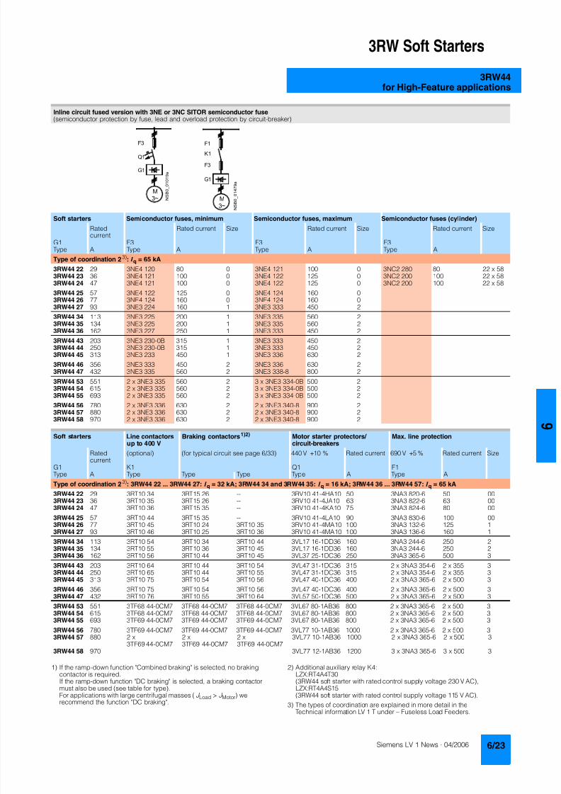
8122019 Arr Estado Solido
httpslidepdfcomreaderfullarr-estado-solido 2740
3RW Soft Starters
3RW44for High-Feature applications
1) If the ramp-down function Combined braking is selected no brakingcontactor is requiredIf the ramp-down function DC braking is selected a braking contactor
must also be used (see table for type)For applications with large centrifugal masses (J Load gt J Motor) werecommend the function DC braking
2) Additional auxiliary relay K4LZXRT4A4T30(3RW44 soft starter with rated control supply voltage 230 V AC)
LZXRT4A4S15(3RW44 soft starter with rated control supply voltage 115 V AC)
3) The types of coordination are explained in more detail in theTechnical information LV 1 T under ndash Fuseless Load Feeders
Inline circuit fused version with 3NE or 3NC SITOR semiconductor fuse(semiconductor protection by fuse lead and overload protection by circuit-breaker)
Soft starters Semiconductor fuses minimum Semiconductor fuses maximum Semiconductor fuses (cylinder)
Ratedcurrent
Rated current Size Rated current Size Rated current Size
G1 F3 F3 F3Type A Type A Type A Type A
Type of coordination 23) I q = 65 kA
3RW44 22 29 3NE4 120 80 0 3NE4 121 100 0 3NC2 280 80 22 x 58
3RW44 23 36 3NE4 121 100 0 3NE4 122 125 0 3NC2 200 100 22 x 583RW44 24 47 3NE4 121 100 0 3NE4 122 125 0 3NC2 200 100 22 x 58
3RW44 25 57 3NE4 122 125 0 3NE4 124 160 03RW44 26 77 3NE4 124 160 0 3NE4 124 160 03RW44 27 93 3NE3 224 160 1 3NE3 333 450 2
3RW44 34 113 3NE3 225 200 1 3NE3 335 560 23RW44 35 134 3NE3 225 200 1 3NE3 335 560 23RW44 36 162 3NE3 227 250 1 3NE3 333 450 2
3RW44 43 203 3NE3 230-0B 315 1 3NE3 333 450 23RW44 44 250 3NE3 230-0B 315 1 3NE3 333 450 23RW44 45 313 3NE3 233 450 1 3NE3 336 630 2
3RW44 46 356 3NE3 333 450 2 3NE3 336 630 23RW44 47 432 3NE3 335 560 2 3NE3 338-8 800 2
3RW44 53 551 2 x 3NE3 335 560 2 3 x 3NE3 334-0B 500 23RW44 54 615 2 x 3NE3 335 560 2 3 x 3NE3 334-0B 500 23RW44 55 693 2 x 3NE3 335 560 2 3 x 3NE3 334-0B 500 2
3RW44 56 780 2 x 3NE3 336 630 2 2 x 3NE3 340-8 900 2
3RW44 57 880 2 x 3NE3 336 630 2 2 x 3NE3 340-8 900 23RW44 58 970 2 x 3NE3 336 630 2 2 x 3NE3 340-8 900 2
Soft starters Line contactorsup to 400 V
Braking contactors1)2) Motor starter protectors circuit-breakers
Max line protection
Ratedcurrent
(optional) (for typical circuit see page 633) 440 V +10 Rated current 690 V +5 Rated current Size
G1 K1 Q1 F1Type A Type Type Type Type A Type A
Type of coordination 23) 3RW44 22 3RW44 27 I q = 32 kA 3RW44 34 and 3RW44 35 I q = 16 kA 3RW44 36 3RW44 57 I q = 65 kA
3RW44 22 29 3RT10 34 3RT15 26 -- 3RV10 41-4HA10 50 3NA3 820-6 50 003RW44 23 36 3RT10 35 3RT15 26 -- 3RV10 41-4JA10 63 3NA3 822-6 63 003RW44 24 47 3RT10 36 3RT15 35 -- 3RV10 41-4KA10 75 3NA3 824-6 80 00
3RW44 25 57 3RT10 44 3RT15 35 -- 3RV10 41-4LA10 90 3NA3 830-6 100 003RW44 26 77 3RT10 45 3RT10 24 3RT10 35 3RV10 41-4MA10 100 3NA3 132-6 125 13RW44 27 93 3RT10 46 3RT10 25 3RT10 36 3RV10 41-4MA10 100 3NA3 136-6 160 1
3RW44 34 113 3RT10 54 3RT10 34 3RT10 44 3VL17 16-1DD36 160 3NA3 244-6 250 2
3RW44 35 134 3RT10 55 3RT10 36 3RT10 45 3VL17 16-1DD36 160 3NA3 244-6 250 23RW44 36 162 3RT10 56 3RT10 44 3RT10 45 3VL37 25-1DC36 250 3NA3 365-6 500 3
3RW44 43 203 3RT10 64 3RT10 44 3RT10 54 3VL47 31-1DC36 315 2 x 3NA3 354-6 2 x 355 33RW44 44 250 3RT10 65 3RT10 44 3RT10 55 3VL47 31-1DC36 315 2 x 3NA3 354-6 2 x 355 33RW44 45 313 3RT10 75 3RT10 54 3RT10 56 3VL47 40-1DC36 400 2 x 3NA3 365-6 2 x 500 3
3RW44 46 356 3RT10 75 3RT10 54 3RT10 56 3VL47 40-1DC36 400 2 x 3NA3 365-6 2 x 500 33RW44 47 432 3RT10 76 3RT10 55 3RT10 64 3VL57 50-1DC36 500 2 x 3NA3 365-6 2 x 500 3
3RW44 53 551 3TF68 44-0CM7 3TF68 44-0CM7 3TF68 44-0CM7 3VL67 80-1AB36 800 2 x 3NA3 365-6 2 x 500 33RW44 54 615 3TF68 44-0CM7 3TF68 44-0CM7 3TF68 44-0CM7 3VL67 80-1AB36 800 2 x 3NA3 365-6 2 x 500 33RW44 55 693 3TF69 44-0CM7 3TF69 44-0CM7 3TF69 44-0CM7 3VL67 80-1AB36 800 2 x 3NA3 365-6 2 x 500 3
3RW44 56 780 3TF69 44-0CM7 3TF69 44-0CM7 3TF69 44-0CM7 3VL77 10-1AB36 1000 2 x 3NA3 365-6 2 x 500 33RW44 57 880 2 x
3TF69 44-0CM72 x3TF69 44-0CM7
2 x3TF69 44-0CM7
3VL77 10-1AB36 1000 2 x 3NA3 365-6 2 x 500 3
3RW44 58 970 3VL77 12-1AB36 1200 3 x 3NA3 365-6 3 x 500 3
8122019 Arr Estado Solido
httpslidepdfcomreaderfullarr-estado-solido 2840
3RW Soft Starters
3RW44for High-Feature applications
1) The types of coordination are explained in more detail in theTechnical information LV 1 T under ndash Fuseless Load FeedersThe type of coordination 2 only refers to soft starters not to feeder compo-nents ( I q = 65 kA)
Inside-delta circuit fused version with 3NE or 3NC SITOR fuses(semiconductor protection by fuse lead and overload protection by circuit-breaker)
Soft starters Semiconductor fuses minimum Semiconductor fuses maximum Semiconductor fuses (cylinder)
Ratedcurrent
Rated current Size Rated current Size Rated current Size
G1 F3 F3 F3Type A Type A Type A Type A
Type of coordination 21)
3RW44 22 50 3NE4 120 80 0 3NE4 121 100 0 3NC2 280 80 22 x 58
3RW44 23 62 3NE4 121 100 0 3NE4 122 125 0 3NC2 200 100 22 x 583RW44 24 81 3NE4 121 100 0 3NE4 122 125 0 3NC2 200 100 22 x 58
3RW44 25 99 3NE4 122 125 0 3NE4 124 160 03RW44 26 133 3NE4 124 160 0 3NE4 124 160 03RW44 27 161 3NE3 224 160 1 3NE3 333 450 2
3RW44 34 196 3NE3 225 200 1 3NE3 335 560 23RW44 35 232 3NE3 225 200 1 3NE3 335 560 23RW44 36 281 3NE3 227 250 1 3NE3 333 450 2
3RW44 43 352 3NE3 230-0B 315 1 3NE3 333 450 23RW44 44 433 3NE3 230-0B 315 1 3NE3 333 450 23RW44 45 542 3NE3 233 450 1 3NE3 336 630 2
3RW44 46 617 3NE3 333 450 2 3NE3 336 630 23RW44 47 748 3NE3 335 560 2 3NE3 338-8 800 2
3RW44 53 954 2 x 3NE3 335 560 2 3 x 3NE3 334-0B 500 23RW44 54 1065 2 x 3NE3 335 560 2 3 x 3NE3 334-0B 500 23RW44 55 1200 2 x 3NE3 335 560 2 3 x 3NE3 334-0B 500 2
3RW44 56 1351 2 x 3NE3 336 630 2 2 x 3NE3 340-8 900 2
3RW44 57 1524 2 x 3NE3 336 630 2 3 x 3NE3 340-8 900 23RW44 58 1680 2 x 3NE3 336 630 2 3 x 3NE3 340-8 900 2
Soft starters Line contactorsup to 400 V
Motor starter protectors cirduit-breakers
Line protections
Ratedcurrent
(optional) 440 V +10 Rated current 690 V +5 Rated current Size
G1 K1 Q1 F1Type A Type Type A Type A
Type of coordination 21)
3RW44 22 50 3RT10 36-1AP04 3RV10 4-4KA10 75 3NA3 824-6 80 003RW44 23 62 3RT10 44-1AP04 3RV10 4-4LA10 90 3NA3 830-6 100 003RW44 24 81 3RT10 46-1AP04 3RV10 4-4MA10 100 3NA3 132-6 125 1
3RW44 25 99 3RT10 54-1AP36 3VL27 16-DC36 160 3NA3 136-6 160 13RW44 26 133 3RT10 55-6AP36 3VL27 16-DC36 160 3NA3 240-6 200 23RW44 27 161 3RT10 56-6AP36 3VL37 20-DC36 200 3NA3 244-6 250 2
3RW44 34 196 3RT10 64-6AP36 3VL37 25-DC36 250 3NA3 360-6 400 3
3RW44 35 232 3RT10 65-6AP36 3VL47 31-DC36 315 3NA3 360-6 400 33RW44 36 281 3RT10 66-6AP36 3VL47 40-DC36 400 2 x 3NA3 360-6 2 x 400 3
3RW44 43 352 3RT10 75-6AP36 3VL47 40-DC36 400 2 x 3NA3 365-6 2 x 500 33RW44 44 433 3RT10 76-6AP36 3VL57 50-DC36 500 2 x 3NA3 365-6 2 x 500 33RW44 45 542 3TF68 44-0CM7 3VL57 63-DC36 800 3 x 3NA3 365-6 3 x 500 3
3RW44 46 617 3TF68 44-0CM7 3VL67 80-AB36 800 3 x 3NA3 365-6 3 x 500 33RW44 47 748 3TF69 3VL67 80-AB36 1000 3 x 3NA3 365-6 3 x 500 3
3RW44 53 954 2 x 3TF68 44-0CM7 3VL77 10-AB36 1000 3 x 3NA3 365-6 3 x 500 33RW44 54 1065 2 x 3TF68 44-0CM7 3VL77 12-AB36 1250 3 x 3NA3 365-6 3 x 500 33RW44 55 1200 2 x 3TF69 44-0CM7 3VL87 16-AB36 1600 3 x 3NA3 365-6 3 x 500 3
3RW44 56 1351 2 x 3TF69 44-0CM7 3VL87 16-AB36 1600 3 x 3NA3 372 3 x 630 33RW44 57 1524 2 x 3TF69 44-0CM7 3VL87 16-AB36 1600 3 x 3NA3 372 3 x 630 33RW44 58 1680 3WL12 20 2000 2 x 3NA3 480 2 x 1000 4
8122019 Arr Estado Solido
httpslidepdfcomreaderfullarr-estado-solido 2940
3RW Soft Starters
3RW44for High-Feature applications
Characteristic curves
Motor protection tripping characteristics for 3RW44(with symmetry)
Admissible mounting height
The admissible operational voltage is reduced to 460 V with a mountingheight of more than 2000 m
Motor protection characteristics for 3RW44(with phase unbalance)
e
2 4 6 101
Class 10 Class 15 Class 20
100
101
102
103
2
4
6
2
4
6
2
4
6
Class 5 Class 30
N S B 0
_ 0 1 5 0 0 a
[ s ]
x
T r i p p i n g t i m e
85
105
70
75
80
90
95
100
N S B 0
_ 0 1 7 0 4
0 1000 2000 3000 4000 5000 O p e r
a t i o n a
l r a
t e d c u r r e n
t I
i n
Mounting height in m
e
e
1001
Class 10 Class 15 Class 20
100
101
102
103
2
4
6
2
4
6
2
4
6
Class 5 Class 30
N S B 0
_ 0 1 7 0 6
[ s ]
x10
T r i p p
i n g
t i m e
8122019 Arr Estado Solido
httpslidepdfcomreaderfullarr-estado-solido 3040
3RW Soft Starters
3RW44for High-Feature applications
More information
Application examples for normal starting (Class 10)
Application examples for heavy starting (Class 20)
Application examples for very heavy starting (Class 30)
NoteThese tables present sample setting values and device sizesThey are intended only for the purposes of information and arenot binding The setting values depend on the application inquestion and must be optimized during commissioningThe soft starter dimensions should be checked where necessarywith the Win-Soft Starter software or with the help ofTechnical Assistance
Normal starting Class 10 (up to 20 s with 350 I n motor)The soft starter rating can be selected to be as high as the rating of the motor used
Application Conveyor belts Roller conveyors Compressors Small ventilators Pumps Hydraulic pumps
Starting parameters
bull Voltage ramp and currentlimiting- Starting voltage 70 60 50 30 30 30- Starting time s 10 10 10 10 10 10- Current limit value Deactivated Deactivated 4 x I M 4 x I M Deactivated Deactivated
bull Torque ramp- Starting torque 60 50 40 20 10 10- End torque 150 150 150 150 150 150- Starting time 10 10 10 10 10 10
bull Breakaway pulse Deactivated (0 ms) Deactivated (0 ms) Deactivated (0 ms) Deactivated (0 ms) Deactivated (0 ms) Deactivated (0 ms)
Ramp-down mode Smoothramp-down
Smoothramp-down
Free ramp-down Free ramp-down Pump ramp-down Free ramp-down
Heavy starting Class 20 (up to 40 s with 350 I n motor)The soft starter has to be selected one rating class higher than the motor used
Application Stirrers Centrifuges Milling machines
Starting parameters
bull Voltage ramp and currentlimiting- Starting voltage 30 30 30- Starting time s 30 30 30- Current limit value 4 x I M 4 x I M 4 x I M
bull Torque ramp- Starting torque 30 30 30- End torque 150 150 150- Starting time 30 30 30
bull Breakaway pulse Deactivated (0 ms) Deactivated (0 ms) Deactivated (0 ms)
Ramp-down mode Free ramp-down Free ramp-down Free ramp-down or DC braking
Very heavy starting Class 30 (up to 60 s with 350 I n motor)The soft starter has to be selected two rating classes higher than the motor used
Application Large ventilators Mills Breakers Circular sawbandsaws
Starting parameters
bull Voltage ramp and currentlimiting- Starting voltage 30 50 50 30- Starting time s 60 60 60 60- Current limit value 4 x I M 4 x I M 4 x I M 4 x I M
bull Torque ramp- Starting torque 20 50 50 20- End torque 150 150 150 150- Starting time 60 60 60 60
bull Breakaway pulse Deactivated (0 ms) 80 300 ms 80 300 ms Deactivated (0 ms)
Ramp-down mode Free ramp-down Free ramp-down Free ramp-down Free ramp-down
8122019 Arr Estado Solido
httpslidepdfcomreaderfullarr-estado-solido 3140
3RW Soft Starters
3RW44for High-Feature applications
Circuit concept
The SIRIUS 3RW44 soft starters can be operated in two differenttypes of circuit
bull Inline circuitThe controls for isolating and protecting the motor are simplyconnected in series with the soft starter The motor isconnected to the soft starter with three leads
bull Inside-delta circuitThe wiring is similar to that of wye-delta starters The phases ofthe soft starter are connected in series with the individual motorwindings The soft starter then only has to carry the phasecurrent amounting to about 58 of the rated motor current(conductor current)
Comparison of the types of circuit
Inline circuitRated current I e corresponds to the rated motor current I n3 leads to the motor
Inside-delta circuit
Rated current I e corresponds to approx 58 of the rated motorcurrent I n6 leads to the motor (as with wye-delta starters)
Which circuit
Using the inline circuit involves the lowest wiring complexityIf the soft starter to motor connections are long this contactsequence is preferableWith the inside-delta circuit there is double the wiring complexitybut a smaller size of device can be used at the same rating
Thanks to choosing the operational mode between the inline cir-cuit and inside-delta circuit the most favorable solution can al-ways be chosen
The braking function is possible only in the inline circuit
Configuration
The 3RW44 solid-state soft starters are designed for normalstarting In case of heavy starting or increased starting
frequency a larger device must be selectedFor long starting times it is recommended to have a PTC ther-mistor detector in the motor This also applies for the ramp-downmodes smooth ramp-down pump ramp-down and DC brakingbecause during the ramp-down time in these modes an addi-tional current loading applies in contrast to free ramp-down
In the motor feeder between the SIRIUS 3RW soft starter and themotor no capacitive elements are permitted (eg no reactive-power compensation equipment) In addition neither staticsystems for reactive-power compensation nor dynamic PFC(Power Factor Correction) must be operated in parallel duringstarting and ramp-down of the soft starter This is important toprevent faults arising on the compensation equipment andor thesoft starter
All elements of the main circuit (such as fuses and controls)
should be dimensioned for direct starting following the localshort-circuit conditions Fuses switching devices and overloadrelays must be ordered separately
The harmonic component load for starting currents must betaken into consideration for the selection of motor starterprotectors (selection of release)
NoteWhen switching on three-phase current motors voltage dropsnormally will occur with all types of starters (direct starters star- delta starters soft starters) On principle the feeding transformermust be configured such that when starting the motor thevoltage drop must occur within the admissible tolerance Whenthe feeding transformer is designed quite scarce the control vol- tage (being independent of the main voltage) should be sup- plied with a separate circuit in order to prevent the soft starterfrom switching off
Serial PC interface PROFIBUS DP communication moduleand parameterizing and operating software Soft Starter ES
The solid-state 3RW44 soft starters have a PC interface forcommunicating with the Soft Starter ES 2006 Smart software orto be connected to an external operating and monitoring mod-ule When using the optional communication module PROFIBUSthe 3RW44 soft starter can be connected to the PROFIBUS netand can communicate via GSD file or software Soft Starter ES2006 Professional
Manual for SIRIUS 3RW44
Besides containing all important information on planning com-missioning and servicing the manual also contains suggestedcircuits and the technical specifications for all devices
Win-Soft Starter selection and simulation program
With this software you can simulate and select all Siemens softstarters taking into account various parameters such as mainsproperties motor and load data and special applicationrequirements
The software is a valuable tool which makes complicatedlengthy manual calculations for determining the required softstarters superfluous
You can order the CD-ROM under the following order numberOrder No E20001-D1020-P302-V2-7400
More information can be found on the Internet athttpwwwsiemenscomsoftstarter
8122019 Arr Estado Solido
httpslidepdfcomreaderfullarr-estado-solido 3240
3RW Soft Starters
3RW44for High-Feature applications
SIRIUS soft starter training course (SD-SIRIUSO)
Siemens offers a 2-day training course on the SIRIUS solid-statesoft starters to keep customers and own personnel up-to-date on
configuring commissioning and servicing issuesPlease direct enquiries and applications to
AampD PT 4 (Trainings-Center Erlangen)Werner-von-Siemens-Str 65D-91052 ErlangenTelefon ++49 9131 729262Telefax ++49 9131 728172sibrainindustrysiemenscomhttp wwwsiemenscomsitrain
8122019 Arr Estado Solido
httpslidepdfcomreaderfullarr-estado-solido 3340
3RW Soft Starters
Project planning aids
Dimensional drawings
3RW44 2 3RW44 3 and 3RW44 4 for High-Feature applications
TypeDimension(mm)
a b c d e f g h I k l m n o p q
3RW44 2 180 170 37 11 167 100 240 270 180 148 75 153 7 184 66 M6 10 Nm
3RW44 3 180 170 37 17 167 100 240 270 180 148 75 153 7 198 9 M6 10 Nm
3RW44 4 210 210 48 25 190 140 269 298 205 166 16 166 9 230 11 M8 15 Nm
8122019 Arr Estado Solido
httpslidepdfcomreaderfullarr-estado-solido 3440
3RW Soft Starters
Project planning aids
3RW44 5 for High-Feature applications
147
173
195
118
N S B 0_
0 1 6 5 3
261
290
249
162
152
6 2 3
1 0 5
2 5 3
1 6 5
76
44
470
510
1
5 5
2
0Oslash14 40
6 3 8 5
5 9 0
8122019 Arr Estado Solido
httpslidepdfcomreaderfullarr-estado-solido 3540
3RW Soft Starters
Project planning aids
Schematics
1) Permissible values for main and control voltagesee Technical Specifications
3RW44 connection examples for main and control circuits
Main circuit Control circuitPossibility 1a Possibility 1Inline circuit with circuit-breaker and SITOR fuse(semiconductor protection only)
Control by pushbutton
Main circuit
Possibility 1b Possibility 1cInline circuit with full-rangeprotection (line andsemiconductor protection)
Inline circuit with line andSITOR fuse(semiconductor protection only)
Q1
L3L2L1
G1
F3
T1 T2 T3
M1
N S B 0_
0 1 4 9 0 a
L1 L2 L3
V1U1 W1
MPE 3~
3NPE 400 V AC 50 Hz
(optionalsemiconductorprotection fuse)
13 14 23 24 33 34 95 9896 +
T1 T2IN4IN3IN2IN1L-L+A1
A2
NPE
PE
G1
F2
NSB0_01494a
S t a r t
S 2
R e s e t S
3
StopS1
L1
On periodGrouperror
N o a c t i o n
N o a c t i o n
Noaction
PTC type Aor
Thermoclick
Noaction
1NPE 230 V AC 50 Hz
M o t o r o
n r i g h t
P S
1
1)
8122019 Arr Estado Solido
httpslidepdfcomreaderfullarr-estado-solido 3640
3RW Soft Starters
Project planning aids
1) Permissible values for main and control voltagesee Technical Specifications
2) Caution Risk of restartingThe start command (eg from the PLC) must be reset prior to a resetcommand because a new automatic restart will take place automaticallyif a start command is active after the reset command This appliesespecially in case of motor protection trippingFor safety reasons we recommend incorporating the group error output(terminals 95 and 96) in the controller
Main circuit Control circuit
Possibility 2 Possibility 2Inline circuit with main contactor Control of a main contactor and control by means of PLC
Q1
L3L2L1
G1
K1
F3
L1 L2 L3
T1 T2 T3
M1
N S B 0_
0 1 4 9 5 a
V1U1 W1
MPE 3~
1)
(optionalsemiconductorprotection)
(optional linecontactor if floatingswitching of themotor is planned)
3NPE 400 V AC 50 Hz
13 14 23 24 33 34 95 9896+
T1 T2IN4IN3IN2IN1L-L+A1
A2
NPE
PE
G1
K1NSB0_01496a
F2+24 V DC
M
L1 1NPE AC 230 V 50 Hz1)
Switch-on duration
M o t o r r i g h t
T r i p R e s e t
PLC outputs PLC inputs
N o a c t i o n
N o a c t i o n
No action No action
Group error
PTC type A Thermoclick
(optional line contactorif floating switchingof the motor is planned)
P S 1
ResetStart 2)
8122019 Arr Estado Solido
httpslidepdfcomreaderfullarr-estado-solido 3740
3RW Soft Starters
Project planning aids
1) Permissible values for main and control voltagesee Technical Specifications
2) Caution Risk of restartingThe start command (eg from the PLC) must be reset prior to a resetcommand because a new automatic restart will take place automaticallyif a start command is active after the reset command This applies espe-cially in case of motor protection trippingFor safety reasons we recommend incorporating the group error output(terminals 95 and 96) in the controller
3) If the ramp-down function Combined braking is selected no brakingcontactor is requiredIf the ramp-down function DC braking is selected a braking contactormust be used in addition Type see Fuse Coordination (inline circuit) onpages 621 to 623For applications with large centrifugal masses (J Load gt J Motor) werecommend the function DC brakingThe output 2 must be switched over to DC braking contactor
4) Auxiliary relay K4 egLZXRT4A4T30 (230 V AC rated control supply voltage)LZXRT4A4S15 (115 V AC rated control supply voltage)
Main circuit Control circuit
Possibility 3a Possibility 3aInline circuit with ramp-down function DC braking3)
(for device types 3RW44 22 to 3RW44 25)Control of the braking contactor3)
Main circuit Control circuit
Possibility 3b Possibility 3bInline circuit with ramp-down function DC braking3)
(for device types 3RW44 26 to 3RW44 47)Control of the braking contactor3)
Q1
L3L2
G1
F3
T1 T2 T3
M1
N S B 0_
0 1 5 0 1 a
L1 L2 L3
V1U1 W1
M
K2 K2 K2
PE 3~
1)
2
(optionalsemi-conductorprotection)
L1 3NPE 400 V AC 50 Hz
13 14 23 24 33 34 95 9896 +
T1 T2IN4IN3IN2IN1L-L+A1
A2
NPE
PEG1
K2NSB0_01502
R e s e t
M Start Reset
+24 V DC
K2
F2
1)
2)
No action Group error
N o a c t i o n
N o a c t i o n
On period
PLC output
PTC type Aor
Thermoclick
L1 1NPE 230 V AC 50 Hz
DC braking contactor 3)
K2 K33 3
G1
F3
T1 T2 T3
M1
N S B 0_
0 1
5 0 3 a
L1 L2 L3
V1U1 W1
MPE 3~
Q1
L3L2
1)
(optionalsemi-conductorprotection)
L1 3NPE 400 V AC 50 Hz
13 14 23 24 33 34 95 9896 +
T1 T2IN4IN3IN2IN1L-L+A1
A2
NPE
PE
G1
K4
NSB0_01504
R e s e t
K4 K4
K3 K2
K2 K3
+24 V DC
M Start Reset
F2
1)
2)
4)
PLC output
No action Group error
N o a c t i o n
N o a c t i o n
ON period
PTC type Aor
Thermoclick
M o t o r o n r i g h t
L1 1NPE 230 V AC 50 Hz
DC braking contactor 3)
8122019 Arr Estado Solido
httpslidepdfcomreaderfullarr-estado-solido 3840
3RW Soft Starters
Notes
1) Permissible values for main and control voltagesee Technical Specifications
2) Caution Risk of restartingThe start command (eg from the PLC) must be reset prior to a resetcommand because a new automatic restart will take place automaticallyif a start command is active after the reset command This appliesespecially in case of motor protection trippingFor safety reasons we recommend incorporating the group error output(terminals 95 and 96) in the controller
Main circuit Control circuit
Possibility 4a Possibility 4b Possibility 4Inside-delta circuit Change of direction of rotation for
inside-delta circuitControl by means of PLC
13 14 23 24 33 34 95 9896+
T1 T2IN4IN3IN2IN1L-L+A1
A2
NPE
PEG1
NSB0_01498a
+24 V DC
M
F2
L1 1NPE AC 230 V 50 Hz1)
2)
R e s e t
Switch-onduration
No action
Group error
N o a c t i o n
N o a c t i o n
No action
PTC type A orThermoclick
M o t o r r i g h t
PLC outputs PLC inputs
Start Reset
7
8122019 Arr Estado Solido
httpslidepdfcomreaderfullarr-estado-solido 3940
Appendix
Conditions of sale and delivery
Terms and Conditions of Sale and Delivery
By using this catalog you can acquire hardware and softwareproducts described therein from the Siemens AG subject to the
following terms Please note The scope the quality and the con-ditions for supplies and services including software productsby any Siemens entity having a registered office outside of Ger-many shall be subject exclusively to the General Terms andConditions of the respective Siemens entity
For customers with a seat or registered office in theFederal Republic of Germany
The bdquoGeneral Terms of Paymentldquo as well as the bdquoGeneral Condi-tions for the Supply of Products and Services of the Electricaland Electronics Industryldquo shall apply
For software products the bdquoGeneral License Conditions for Soft-ware Products for Automation and Drives for Customers with aSeat or registered Office in Germanyldquo shall apply
For customers with a seat or registered office outside of
Germany The bdquoGeneral Terms of Paymentldquo as well as the bdquoGeneral Condi-tions for Supplies of Siemens Automation and Drives for Cus-tomers with a Seat or registered Office outside of Germanyldquo shallapply
For software products the bdquoGeneral License Conditions for Soft-ware Products for Automation and Drives for Customers with aSeat or registered Office outside of Germanyldquo shall apply
General
The prices are in 991404 (Euro) ex works exclusive packaging
The sales tax (value added tax) is not included in the pricesIt shall be debited separately at the respective rate according tothe applicable legal regulations
In addition to the prices of products which include silver plump
aluminum andor copper surcharges may be calculated if therespective limits of the notes are exceeded The respective note(eg source German newspaper bdquoHandesblattldquo in categorybdquodeutsche Edelmetalleldquo and bdquoMetallverarbeiterldquo) for silver (bdquover-arbeitetes Silberldquo) plump (bdquoBlei in Kabelnldquo) aluminum (bdquoAlumin-ium in Kabelnldquo) and copper (bdquoElektrolytkupferldquo bdquoDEL-Notizldquo) re-spectively of the day the order or rather the on call order isreceived is decisive for the calculation of the surcharges
Surcharges of copper shall be calculated for Drives at a note(bdquoDEL-Notizldquo) above EUR 22500 100 Kg and for chokes trans-formers above EUR 15000 100 kg
Surcharges shall be charged based on the quantities of the ma-terials which are contained in the relevant products
Prices are subject to change without prior notice We will debitthe prices valid at the time of delivery
The dimensions are in mm In Germany according to the Ger-man law on units in measuring technology data in inches onlyapply to devices for export
Illustrations are not binding
Insofar as there are no remarks on the corresponding pages- especially with regard to data dimensions and weights given -these are subject to change without prior notice
Comprehensive Terms and Conditions of Sale and Delivery areavailable free of charge from your local Siemens business officeunder the following Order Nos
bull 6ZB5310-0KR30-0BA0(for customers based in the Federal Republic of Germany)
bull 6ZB5310-0KS53-0BA0(for customers based outside of theFederal Republic ofGermany)
or download them from the Internethttpwwwsiemenscomautomationmall (Germany AampD Mall Online-Help System)
Export regulations
The products listed in this catalog price list may be subject toEuropean German andor US export regulations
Therefore any export requiring a license is subject to approvalby the competent authorities
According to current provisions the following export regulations
must be observed with respect to the products featured in thiscatalog price list
Even without a label or with an ldquoAL Nldquo or ldquoECCN Nldquo authoriza-tion may be required due to the final destination and purpose forwhich the goods are to be used
The deciding factors are the AL or ECCN export authorizationindicated on order confirmations delivery notes and invoices
Errors excepted and subject to change without prior notice
AampDVuLEn 060306
AL Number of the German Export List
Products marked other than ldquoNldquo require an exportlicenseIn the case of software products the export des-ignations of the relevant data medium must alsobe generally adhered to
Goods labeled with an ldquoAL not equal to Nldquo aresubject to a European or German export authori-zation when being exported out of the EU
ECCN Export Control Classification Number
Products marked other than ldquoNldquo are subject to a
reexport license to specific countriesIn the case of software products the exportdesignations of the relevant data medium mustalso be generally adhered to
Goods labeled with an ldquoECCN not equal to Nldquo aresubject to a US re-export authorization
_ _ _ _
8122019 Arr Estado Solido
httpslidepdfcomreaderfullarr-estado-solido 4040
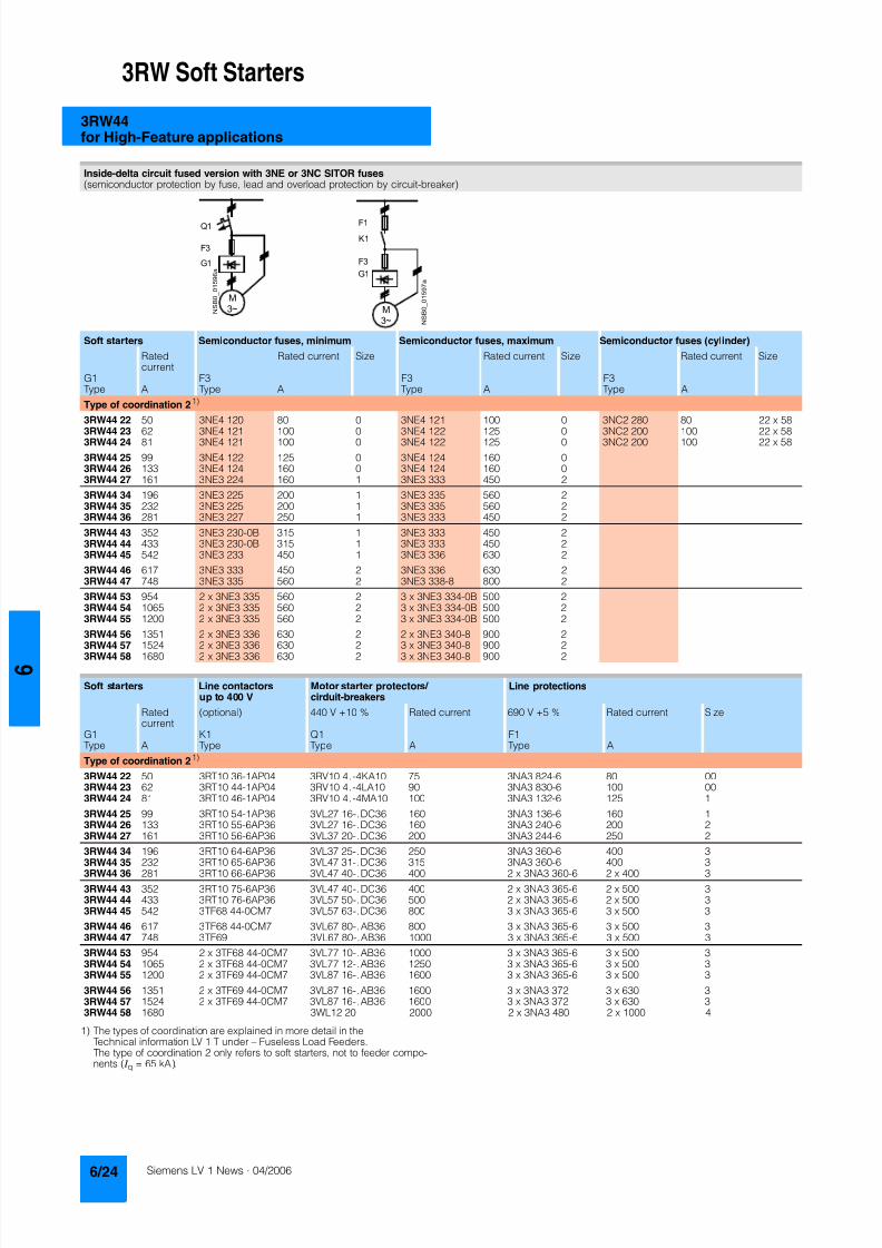
8122019 Arr Estado Solido
httpslidepdfcomreaderfullarr-estado-solido 2840
3RW Soft Starters
3RW44for High-Feature applications
1) The types of coordination are explained in more detail in theTechnical information LV 1 T under ndash Fuseless Load FeedersThe type of coordination 2 only refers to soft starters not to feeder compo-nents ( I q = 65 kA)
Inside-delta circuit fused version with 3NE or 3NC SITOR fuses(semiconductor protection by fuse lead and overload protection by circuit-breaker)
Soft starters Semiconductor fuses minimum Semiconductor fuses maximum Semiconductor fuses (cylinder)
Ratedcurrent
Rated current Size Rated current Size Rated current Size
G1 F3 F3 F3Type A Type A Type A Type A
Type of coordination 21)
3RW44 22 50 3NE4 120 80 0 3NE4 121 100 0 3NC2 280 80 22 x 58
3RW44 23 62 3NE4 121 100 0 3NE4 122 125 0 3NC2 200 100 22 x 583RW44 24 81 3NE4 121 100 0 3NE4 122 125 0 3NC2 200 100 22 x 58
3RW44 25 99 3NE4 122 125 0 3NE4 124 160 03RW44 26 133 3NE4 124 160 0 3NE4 124 160 03RW44 27 161 3NE3 224 160 1 3NE3 333 450 2
3RW44 34 196 3NE3 225 200 1 3NE3 335 560 23RW44 35 232 3NE3 225 200 1 3NE3 335 560 23RW44 36 281 3NE3 227 250 1 3NE3 333 450 2
3RW44 43 352 3NE3 230-0B 315 1 3NE3 333 450 23RW44 44 433 3NE3 230-0B 315 1 3NE3 333 450 23RW44 45 542 3NE3 233 450 1 3NE3 336 630 2
3RW44 46 617 3NE3 333 450 2 3NE3 336 630 23RW44 47 748 3NE3 335 560 2 3NE3 338-8 800 2
3RW44 53 954 2 x 3NE3 335 560 2 3 x 3NE3 334-0B 500 23RW44 54 1065 2 x 3NE3 335 560 2 3 x 3NE3 334-0B 500 23RW44 55 1200 2 x 3NE3 335 560 2 3 x 3NE3 334-0B 500 2
3RW44 56 1351 2 x 3NE3 336 630 2 2 x 3NE3 340-8 900 2
3RW44 57 1524 2 x 3NE3 336 630 2 3 x 3NE3 340-8 900 23RW44 58 1680 2 x 3NE3 336 630 2 3 x 3NE3 340-8 900 2
Soft starters Line contactorsup to 400 V
Motor starter protectors cirduit-breakers
Line protections
Ratedcurrent
(optional) 440 V +10 Rated current 690 V +5 Rated current Size
G1 K1 Q1 F1Type A Type Type A Type A
Type of coordination 21)
3RW44 22 50 3RT10 36-1AP04 3RV10 4-4KA10 75 3NA3 824-6 80 003RW44 23 62 3RT10 44-1AP04 3RV10 4-4LA10 90 3NA3 830-6 100 003RW44 24 81 3RT10 46-1AP04 3RV10 4-4MA10 100 3NA3 132-6 125 1
3RW44 25 99 3RT10 54-1AP36 3VL27 16-DC36 160 3NA3 136-6 160 13RW44 26 133 3RT10 55-6AP36 3VL27 16-DC36 160 3NA3 240-6 200 23RW44 27 161 3RT10 56-6AP36 3VL37 20-DC36 200 3NA3 244-6 250 2
3RW44 34 196 3RT10 64-6AP36 3VL37 25-DC36 250 3NA3 360-6 400 3
3RW44 35 232 3RT10 65-6AP36 3VL47 31-DC36 315 3NA3 360-6 400 33RW44 36 281 3RT10 66-6AP36 3VL47 40-DC36 400 2 x 3NA3 360-6 2 x 400 3
3RW44 43 352 3RT10 75-6AP36 3VL47 40-DC36 400 2 x 3NA3 365-6 2 x 500 33RW44 44 433 3RT10 76-6AP36 3VL57 50-DC36 500 2 x 3NA3 365-6 2 x 500 33RW44 45 542 3TF68 44-0CM7 3VL57 63-DC36 800 3 x 3NA3 365-6 3 x 500 3
3RW44 46 617 3TF68 44-0CM7 3VL67 80-AB36 800 3 x 3NA3 365-6 3 x 500 33RW44 47 748 3TF69 3VL67 80-AB36 1000 3 x 3NA3 365-6 3 x 500 3
3RW44 53 954 2 x 3TF68 44-0CM7 3VL77 10-AB36 1000 3 x 3NA3 365-6 3 x 500 33RW44 54 1065 2 x 3TF68 44-0CM7 3VL77 12-AB36 1250 3 x 3NA3 365-6 3 x 500 33RW44 55 1200 2 x 3TF69 44-0CM7 3VL87 16-AB36 1600 3 x 3NA3 365-6 3 x 500 3
3RW44 56 1351 2 x 3TF69 44-0CM7 3VL87 16-AB36 1600 3 x 3NA3 372 3 x 630 33RW44 57 1524 2 x 3TF69 44-0CM7 3VL87 16-AB36 1600 3 x 3NA3 372 3 x 630 33RW44 58 1680 3WL12 20 2000 2 x 3NA3 480 2 x 1000 4
8122019 Arr Estado Solido
httpslidepdfcomreaderfullarr-estado-solido 2940
3RW Soft Starters
3RW44for High-Feature applications
Characteristic curves
Motor protection tripping characteristics for 3RW44(with symmetry)
Admissible mounting height
The admissible operational voltage is reduced to 460 V with a mountingheight of more than 2000 m
Motor protection characteristics for 3RW44(with phase unbalance)
e
2 4 6 101
Class 10 Class 15 Class 20
100
101
102
103
2
4
6
2
4
6
2
4
6
Class 5 Class 30
N S B 0
_ 0 1 5 0 0 a
[ s ]
x
T r i p p i n g t i m e
85
105
70
75
80
90
95
100
N S B 0
_ 0 1 7 0 4
0 1000 2000 3000 4000 5000 O p e r
a t i o n a
l r a
t e d c u r r e n
t I
i n
Mounting height in m
e
e
1001
Class 10 Class 15 Class 20
100
101
102
103
2
4
6
2
4
6
2
4
6
Class 5 Class 30
N S B 0
_ 0 1 7 0 6
[ s ]
x10
T r i p p
i n g
t i m e
8122019 Arr Estado Solido
httpslidepdfcomreaderfullarr-estado-solido 3040
3RW Soft Starters
3RW44for High-Feature applications
More information
Application examples for normal starting (Class 10)
Application examples for heavy starting (Class 20)
Application examples for very heavy starting (Class 30)
NoteThese tables present sample setting values and device sizesThey are intended only for the purposes of information and arenot binding The setting values depend on the application inquestion and must be optimized during commissioningThe soft starter dimensions should be checked where necessarywith the Win-Soft Starter software or with the help ofTechnical Assistance
Normal starting Class 10 (up to 20 s with 350 I n motor)The soft starter rating can be selected to be as high as the rating of the motor used
Application Conveyor belts Roller conveyors Compressors Small ventilators Pumps Hydraulic pumps
Starting parameters
bull Voltage ramp and currentlimiting- Starting voltage 70 60 50 30 30 30- Starting time s 10 10 10 10 10 10- Current limit value Deactivated Deactivated 4 x I M 4 x I M Deactivated Deactivated
bull Torque ramp- Starting torque 60 50 40 20 10 10- End torque 150 150 150 150 150 150- Starting time 10 10 10 10 10 10
bull Breakaway pulse Deactivated (0 ms) Deactivated (0 ms) Deactivated (0 ms) Deactivated (0 ms) Deactivated (0 ms) Deactivated (0 ms)
Ramp-down mode Smoothramp-down
Smoothramp-down
Free ramp-down Free ramp-down Pump ramp-down Free ramp-down
Heavy starting Class 20 (up to 40 s with 350 I n motor)The soft starter has to be selected one rating class higher than the motor used
Application Stirrers Centrifuges Milling machines
Starting parameters
bull Voltage ramp and currentlimiting- Starting voltage 30 30 30- Starting time s 30 30 30- Current limit value 4 x I M 4 x I M 4 x I M
bull Torque ramp- Starting torque 30 30 30- End torque 150 150 150- Starting time 30 30 30
bull Breakaway pulse Deactivated (0 ms) Deactivated (0 ms) Deactivated (0 ms)
Ramp-down mode Free ramp-down Free ramp-down Free ramp-down or DC braking
Very heavy starting Class 30 (up to 60 s with 350 I n motor)The soft starter has to be selected two rating classes higher than the motor used
Application Large ventilators Mills Breakers Circular sawbandsaws
Starting parameters
bull Voltage ramp and currentlimiting- Starting voltage 30 50 50 30- Starting time s 60 60 60 60- Current limit value 4 x I M 4 x I M 4 x I M 4 x I M
bull Torque ramp- Starting torque 20 50 50 20- End torque 150 150 150 150- Starting time 60 60 60 60
bull Breakaway pulse Deactivated (0 ms) 80 300 ms 80 300 ms Deactivated (0 ms)
Ramp-down mode Free ramp-down Free ramp-down Free ramp-down Free ramp-down
8122019 Arr Estado Solido
httpslidepdfcomreaderfullarr-estado-solido 3140
3RW Soft Starters
3RW44for High-Feature applications
Circuit concept
The SIRIUS 3RW44 soft starters can be operated in two differenttypes of circuit
bull Inline circuitThe controls for isolating and protecting the motor are simplyconnected in series with the soft starter The motor isconnected to the soft starter with three leads
bull Inside-delta circuitThe wiring is similar to that of wye-delta starters The phases ofthe soft starter are connected in series with the individual motorwindings The soft starter then only has to carry the phasecurrent amounting to about 58 of the rated motor current(conductor current)
Comparison of the types of circuit
Inline circuitRated current I e corresponds to the rated motor current I n3 leads to the motor
Inside-delta circuit
Rated current I e corresponds to approx 58 of the rated motorcurrent I n6 leads to the motor (as with wye-delta starters)
Which circuit
Using the inline circuit involves the lowest wiring complexityIf the soft starter to motor connections are long this contactsequence is preferableWith the inside-delta circuit there is double the wiring complexitybut a smaller size of device can be used at the same rating
Thanks to choosing the operational mode between the inline cir-cuit and inside-delta circuit the most favorable solution can al-ways be chosen
The braking function is possible only in the inline circuit
Configuration
The 3RW44 solid-state soft starters are designed for normalstarting In case of heavy starting or increased starting
frequency a larger device must be selectedFor long starting times it is recommended to have a PTC ther-mistor detector in the motor This also applies for the ramp-downmodes smooth ramp-down pump ramp-down and DC brakingbecause during the ramp-down time in these modes an addi-tional current loading applies in contrast to free ramp-down
In the motor feeder between the SIRIUS 3RW soft starter and themotor no capacitive elements are permitted (eg no reactive-power compensation equipment) In addition neither staticsystems for reactive-power compensation nor dynamic PFC(Power Factor Correction) must be operated in parallel duringstarting and ramp-down of the soft starter This is important toprevent faults arising on the compensation equipment andor thesoft starter
All elements of the main circuit (such as fuses and controls)
should be dimensioned for direct starting following the localshort-circuit conditions Fuses switching devices and overloadrelays must be ordered separately
The harmonic component load for starting currents must betaken into consideration for the selection of motor starterprotectors (selection of release)
NoteWhen switching on three-phase current motors voltage dropsnormally will occur with all types of starters (direct starters star- delta starters soft starters) On principle the feeding transformermust be configured such that when starting the motor thevoltage drop must occur within the admissible tolerance Whenthe feeding transformer is designed quite scarce the control vol- tage (being independent of the main voltage) should be sup- plied with a separate circuit in order to prevent the soft starterfrom switching off
Serial PC interface PROFIBUS DP communication moduleand parameterizing and operating software Soft Starter ES
The solid-state 3RW44 soft starters have a PC interface forcommunicating with the Soft Starter ES 2006 Smart software orto be connected to an external operating and monitoring mod-ule When using the optional communication module PROFIBUSthe 3RW44 soft starter can be connected to the PROFIBUS netand can communicate via GSD file or software Soft Starter ES2006 Professional
Manual for SIRIUS 3RW44
Besides containing all important information on planning com-missioning and servicing the manual also contains suggestedcircuits and the technical specifications for all devices
Win-Soft Starter selection and simulation program
With this software you can simulate and select all Siemens softstarters taking into account various parameters such as mainsproperties motor and load data and special applicationrequirements
The software is a valuable tool which makes complicatedlengthy manual calculations for determining the required softstarters superfluous
You can order the CD-ROM under the following order numberOrder No E20001-D1020-P302-V2-7400
More information can be found on the Internet athttpwwwsiemenscomsoftstarter
8122019 Arr Estado Solido
httpslidepdfcomreaderfullarr-estado-solido 3240
3RW Soft Starters
3RW44for High-Feature applications
SIRIUS soft starter training course (SD-SIRIUSO)
Siemens offers a 2-day training course on the SIRIUS solid-statesoft starters to keep customers and own personnel up-to-date on
configuring commissioning and servicing issuesPlease direct enquiries and applications to
AampD PT 4 (Trainings-Center Erlangen)Werner-von-Siemens-Str 65D-91052 ErlangenTelefon ++49 9131 729262Telefax ++49 9131 728172sibrainindustrysiemenscomhttp wwwsiemenscomsitrain
8122019 Arr Estado Solido
httpslidepdfcomreaderfullarr-estado-solido 3340
3RW Soft Starters
Project planning aids
Dimensional drawings
3RW44 2 3RW44 3 and 3RW44 4 for High-Feature applications
TypeDimension(mm)
a b c d e f g h I k l m n o p q
3RW44 2 180 170 37 11 167 100 240 270 180 148 75 153 7 184 66 M6 10 Nm
3RW44 3 180 170 37 17 167 100 240 270 180 148 75 153 7 198 9 M6 10 Nm
3RW44 4 210 210 48 25 190 140 269 298 205 166 16 166 9 230 11 M8 15 Nm
8122019 Arr Estado Solido
httpslidepdfcomreaderfullarr-estado-solido 3440
3RW Soft Starters
Project planning aids
3RW44 5 for High-Feature applications
147
173
195
118
N S B 0_
0 1 6 5 3
261
290
249
162
152
6 2 3
1 0 5
2 5 3
1 6 5
76
44
470
510
1
5 5
2
0Oslash14 40
6 3 8 5
5 9 0
8122019 Arr Estado Solido
httpslidepdfcomreaderfullarr-estado-solido 3540
3RW Soft Starters
Project planning aids
Schematics
1) Permissible values for main and control voltagesee Technical Specifications
3RW44 connection examples for main and control circuits
Main circuit Control circuitPossibility 1a Possibility 1Inline circuit with circuit-breaker and SITOR fuse(semiconductor protection only)
Control by pushbutton
Main circuit
Possibility 1b Possibility 1cInline circuit with full-rangeprotection (line andsemiconductor protection)
Inline circuit with line andSITOR fuse(semiconductor protection only)
Q1
L3L2L1
G1
F3
T1 T2 T3
M1
N S B 0_
0 1 4 9 0 a
L1 L2 L3
V1U1 W1
MPE 3~
3NPE 400 V AC 50 Hz
(optionalsemiconductorprotection fuse)
13 14 23 24 33 34 95 9896 +
T1 T2IN4IN3IN2IN1L-L+A1
A2
NPE
PE
G1
F2
NSB0_01494a
S t a r t
S 2
R e s e t S
3
StopS1
L1
On periodGrouperror
N o a c t i o n
N o a c t i o n
Noaction
PTC type Aor
Thermoclick
Noaction
1NPE 230 V AC 50 Hz
M o t o r o
n r i g h t
P S
1
1)
8122019 Arr Estado Solido
httpslidepdfcomreaderfullarr-estado-solido 3640
3RW Soft Starters
Project planning aids
1) Permissible values for main and control voltagesee Technical Specifications
2) Caution Risk of restartingThe start command (eg from the PLC) must be reset prior to a resetcommand because a new automatic restart will take place automaticallyif a start command is active after the reset command This appliesespecially in case of motor protection trippingFor safety reasons we recommend incorporating the group error output(terminals 95 and 96) in the controller
Main circuit Control circuit
Possibility 2 Possibility 2Inline circuit with main contactor Control of a main contactor and control by means of PLC
Q1
L3L2L1
G1
K1
F3
L1 L2 L3
T1 T2 T3
M1
N S B 0_
0 1 4 9 5 a
V1U1 W1
MPE 3~
1)
(optionalsemiconductorprotection)
(optional linecontactor if floatingswitching of themotor is planned)
3NPE 400 V AC 50 Hz
13 14 23 24 33 34 95 9896+
T1 T2IN4IN3IN2IN1L-L+A1
A2
NPE
PE
G1
K1NSB0_01496a
F2+24 V DC
M
L1 1NPE AC 230 V 50 Hz1)
Switch-on duration
M o t o r r i g h t
T r i p R e s e t
PLC outputs PLC inputs
N o a c t i o n
N o a c t i o n
No action No action
Group error
PTC type A Thermoclick
(optional line contactorif floating switchingof the motor is planned)
P S 1
ResetStart 2)
8122019 Arr Estado Solido
httpslidepdfcomreaderfullarr-estado-solido 3740
3RW Soft Starters
Project planning aids
1) Permissible values for main and control voltagesee Technical Specifications
2) Caution Risk of restartingThe start command (eg from the PLC) must be reset prior to a resetcommand because a new automatic restart will take place automaticallyif a start command is active after the reset command This applies espe-cially in case of motor protection trippingFor safety reasons we recommend incorporating the group error output(terminals 95 and 96) in the controller
3) If the ramp-down function Combined braking is selected no brakingcontactor is requiredIf the ramp-down function DC braking is selected a braking contactormust be used in addition Type see Fuse Coordination (inline circuit) onpages 621 to 623For applications with large centrifugal masses (J Load gt J Motor) werecommend the function DC brakingThe output 2 must be switched over to DC braking contactor
4) Auxiliary relay K4 egLZXRT4A4T30 (230 V AC rated control supply voltage)LZXRT4A4S15 (115 V AC rated control supply voltage)
Main circuit Control circuit
Possibility 3a Possibility 3aInline circuit with ramp-down function DC braking3)
(for device types 3RW44 22 to 3RW44 25)Control of the braking contactor3)
Main circuit Control circuit
Possibility 3b Possibility 3bInline circuit with ramp-down function DC braking3)
(for device types 3RW44 26 to 3RW44 47)Control of the braking contactor3)
Q1
L3L2
G1
F3
T1 T2 T3
M1
N S B 0_
0 1 5 0 1 a
L1 L2 L3
V1U1 W1
M
K2 K2 K2
PE 3~
1)
2
(optionalsemi-conductorprotection)
L1 3NPE 400 V AC 50 Hz
13 14 23 24 33 34 95 9896 +
T1 T2IN4IN3IN2IN1L-L+A1
A2
NPE
PEG1
K2NSB0_01502
R e s e t
M Start Reset
+24 V DC
K2
F2
1)
2)
No action Group error
N o a c t i o n
N o a c t i o n
On period
PLC output
PTC type Aor
Thermoclick
L1 1NPE 230 V AC 50 Hz
DC braking contactor 3)
K2 K33 3
G1
F3
T1 T2 T3
M1
N S B 0_
0 1
5 0 3 a
L1 L2 L3
V1U1 W1
MPE 3~
Q1
L3L2
1)
(optionalsemi-conductorprotection)
L1 3NPE 400 V AC 50 Hz
13 14 23 24 33 34 95 9896 +
T1 T2IN4IN3IN2IN1L-L+A1
A2
NPE
PE
G1
K4
NSB0_01504
R e s e t
K4 K4
K3 K2
K2 K3
+24 V DC
M Start Reset
F2
1)
2)
4)
PLC output
No action Group error
N o a c t i o n
N o a c t i o n
ON period
PTC type Aor
Thermoclick
M o t o r o n r i g h t
L1 1NPE 230 V AC 50 Hz
DC braking contactor 3)
8122019 Arr Estado Solido
httpslidepdfcomreaderfullarr-estado-solido 3840
3RW Soft Starters
Notes
1) Permissible values for main and control voltagesee Technical Specifications
2) Caution Risk of restartingThe start command (eg from the PLC) must be reset prior to a resetcommand because a new automatic restart will take place automaticallyif a start command is active after the reset command This appliesespecially in case of motor protection trippingFor safety reasons we recommend incorporating the group error output(terminals 95 and 96) in the controller
Main circuit Control circuit
Possibility 4a Possibility 4b Possibility 4Inside-delta circuit Change of direction of rotation for
inside-delta circuitControl by means of PLC
13 14 23 24 33 34 95 9896+
T1 T2IN4IN3IN2IN1L-L+A1
A2
NPE
PEG1
NSB0_01498a
+24 V DC
M
F2
L1 1NPE AC 230 V 50 Hz1)
2)
R e s e t
Switch-onduration
No action
Group error
N o a c t i o n
N o a c t i o n
No action
PTC type A orThermoclick
M o t o r r i g h t
PLC outputs PLC inputs
Start Reset
7
8122019 Arr Estado Solido
httpslidepdfcomreaderfullarr-estado-solido 3940
Appendix
Conditions of sale and delivery
Terms and Conditions of Sale and Delivery
By using this catalog you can acquire hardware and softwareproducts described therein from the Siemens AG subject to the
following terms Please note The scope the quality and the con-ditions for supplies and services including software productsby any Siemens entity having a registered office outside of Ger-many shall be subject exclusively to the General Terms andConditions of the respective Siemens entity
For customers with a seat or registered office in theFederal Republic of Germany
The bdquoGeneral Terms of Paymentldquo as well as the bdquoGeneral Condi-tions for the Supply of Products and Services of the Electricaland Electronics Industryldquo shall apply
For software products the bdquoGeneral License Conditions for Soft-ware Products for Automation and Drives for Customers with aSeat or registered Office in Germanyldquo shall apply
For customers with a seat or registered office outside of
Germany The bdquoGeneral Terms of Paymentldquo as well as the bdquoGeneral Condi-tions for Supplies of Siemens Automation and Drives for Cus-tomers with a Seat or registered Office outside of Germanyldquo shallapply
For software products the bdquoGeneral License Conditions for Soft-ware Products for Automation and Drives for Customers with aSeat or registered Office outside of Germanyldquo shall apply
General
The prices are in 991404 (Euro) ex works exclusive packaging
The sales tax (value added tax) is not included in the pricesIt shall be debited separately at the respective rate according tothe applicable legal regulations
In addition to the prices of products which include silver plump
aluminum andor copper surcharges may be calculated if therespective limits of the notes are exceeded The respective note(eg source German newspaper bdquoHandesblattldquo in categorybdquodeutsche Edelmetalleldquo and bdquoMetallverarbeiterldquo) for silver (bdquover-arbeitetes Silberldquo) plump (bdquoBlei in Kabelnldquo) aluminum (bdquoAlumin-ium in Kabelnldquo) and copper (bdquoElektrolytkupferldquo bdquoDEL-Notizldquo) re-spectively of the day the order or rather the on call order isreceived is decisive for the calculation of the surcharges
Surcharges of copper shall be calculated for Drives at a note(bdquoDEL-Notizldquo) above EUR 22500 100 Kg and for chokes trans-formers above EUR 15000 100 kg
Surcharges shall be charged based on the quantities of the ma-terials which are contained in the relevant products
Prices are subject to change without prior notice We will debitthe prices valid at the time of delivery
The dimensions are in mm In Germany according to the Ger-man law on units in measuring technology data in inches onlyapply to devices for export
Illustrations are not binding
Insofar as there are no remarks on the corresponding pages- especially with regard to data dimensions and weights given -these are subject to change without prior notice
Comprehensive Terms and Conditions of Sale and Delivery areavailable free of charge from your local Siemens business officeunder the following Order Nos
bull 6ZB5310-0KR30-0BA0(for customers based in the Federal Republic of Germany)
bull 6ZB5310-0KS53-0BA0(for customers based outside of theFederal Republic ofGermany)
or download them from the Internethttpwwwsiemenscomautomationmall (Germany AampD Mall Online-Help System)
Export regulations
The products listed in this catalog price list may be subject toEuropean German andor US export regulations
Therefore any export requiring a license is subject to approvalby the competent authorities
According to current provisions the following export regulations
must be observed with respect to the products featured in thiscatalog price list
Even without a label or with an ldquoAL Nldquo or ldquoECCN Nldquo authoriza-tion may be required due to the final destination and purpose forwhich the goods are to be used
The deciding factors are the AL or ECCN export authorizationindicated on order confirmations delivery notes and invoices
Errors excepted and subject to change without prior notice
AampDVuLEn 060306
AL Number of the German Export List
Products marked other than ldquoNldquo require an exportlicenseIn the case of software products the export des-ignations of the relevant data medium must alsobe generally adhered to
Goods labeled with an ldquoAL not equal to Nldquo aresubject to a European or German export authori-zation when being exported out of the EU
ECCN Export Control Classification Number
Products marked other than ldquoNldquo are subject to a
reexport license to specific countriesIn the case of software products the exportdesignations of the relevant data medium mustalso be generally adhered to
Goods labeled with an ldquoECCN not equal to Nldquo aresubject to a US re-export authorization
_ _ _ _
8122019 Arr Estado Solido
httpslidepdfcomreaderfullarr-estado-solido 4040
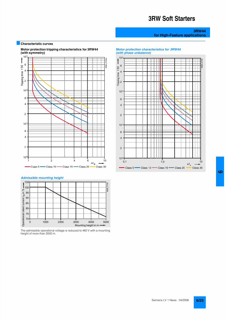
8122019 Arr Estado Solido
httpslidepdfcomreaderfullarr-estado-solido 2940
3RW Soft Starters
3RW44for High-Feature applications
Characteristic curves
Motor protection tripping characteristics for 3RW44(with symmetry)
Admissible mounting height
The admissible operational voltage is reduced to 460 V with a mountingheight of more than 2000 m
Motor protection characteristics for 3RW44(with phase unbalance)
e
2 4 6 101
Class 10 Class 15 Class 20
100
101
102
103
2
4
6
2
4
6
2
4
6
Class 5 Class 30
N S B 0
_ 0 1 5 0 0 a
[ s ]
x
T r i p p i n g t i m e
85
105
70
75
80
90
95
100
N S B 0
_ 0 1 7 0 4
0 1000 2000 3000 4000 5000 O p e r
a t i o n a
l r a
t e d c u r r e n
t I
i n
Mounting height in m
e
e
1001
Class 10 Class 15 Class 20
100
101
102
103
2
4
6
2
4
6
2
4
6
Class 5 Class 30
N S B 0
_ 0 1 7 0 6
[ s ]
x10
T r i p p
i n g
t i m e
8122019 Arr Estado Solido
httpslidepdfcomreaderfullarr-estado-solido 3040
3RW Soft Starters
3RW44for High-Feature applications
More information
Application examples for normal starting (Class 10)
Application examples for heavy starting (Class 20)
Application examples for very heavy starting (Class 30)
NoteThese tables present sample setting values and device sizesThey are intended only for the purposes of information and arenot binding The setting values depend on the application inquestion and must be optimized during commissioningThe soft starter dimensions should be checked where necessarywith the Win-Soft Starter software or with the help ofTechnical Assistance
Normal starting Class 10 (up to 20 s with 350 I n motor)The soft starter rating can be selected to be as high as the rating of the motor used
Application Conveyor belts Roller conveyors Compressors Small ventilators Pumps Hydraulic pumps
Starting parameters
bull Voltage ramp and currentlimiting- Starting voltage 70 60 50 30 30 30- Starting time s 10 10 10 10 10 10- Current limit value Deactivated Deactivated 4 x I M 4 x I M Deactivated Deactivated
bull Torque ramp- Starting torque 60 50 40 20 10 10- End torque 150 150 150 150 150 150- Starting time 10 10 10 10 10 10
bull Breakaway pulse Deactivated (0 ms) Deactivated (0 ms) Deactivated (0 ms) Deactivated (0 ms) Deactivated (0 ms) Deactivated (0 ms)
Ramp-down mode Smoothramp-down
Smoothramp-down
Free ramp-down Free ramp-down Pump ramp-down Free ramp-down
Heavy starting Class 20 (up to 40 s with 350 I n motor)The soft starter has to be selected one rating class higher than the motor used
Application Stirrers Centrifuges Milling machines
Starting parameters
bull Voltage ramp and currentlimiting- Starting voltage 30 30 30- Starting time s 30 30 30- Current limit value 4 x I M 4 x I M 4 x I M
bull Torque ramp- Starting torque 30 30 30- End torque 150 150 150- Starting time 30 30 30
bull Breakaway pulse Deactivated (0 ms) Deactivated (0 ms) Deactivated (0 ms)
Ramp-down mode Free ramp-down Free ramp-down Free ramp-down or DC braking
Very heavy starting Class 30 (up to 60 s with 350 I n motor)The soft starter has to be selected two rating classes higher than the motor used
Application Large ventilators Mills Breakers Circular sawbandsaws
Starting parameters
bull Voltage ramp and currentlimiting- Starting voltage 30 50 50 30- Starting time s 60 60 60 60- Current limit value 4 x I M 4 x I M 4 x I M 4 x I M
bull Torque ramp- Starting torque 20 50 50 20- End torque 150 150 150 150- Starting time 60 60 60 60
bull Breakaway pulse Deactivated (0 ms) 80 300 ms 80 300 ms Deactivated (0 ms)
Ramp-down mode Free ramp-down Free ramp-down Free ramp-down Free ramp-down
8122019 Arr Estado Solido
httpslidepdfcomreaderfullarr-estado-solido 3140
3RW Soft Starters
3RW44for High-Feature applications
Circuit concept
The SIRIUS 3RW44 soft starters can be operated in two differenttypes of circuit
bull Inline circuitThe controls for isolating and protecting the motor are simplyconnected in series with the soft starter The motor isconnected to the soft starter with three leads
bull Inside-delta circuitThe wiring is similar to that of wye-delta starters The phases ofthe soft starter are connected in series with the individual motorwindings The soft starter then only has to carry the phasecurrent amounting to about 58 of the rated motor current(conductor current)
Comparison of the types of circuit
Inline circuitRated current I e corresponds to the rated motor current I n3 leads to the motor
Inside-delta circuit
Rated current I e corresponds to approx 58 of the rated motorcurrent I n6 leads to the motor (as with wye-delta starters)
Which circuit
Using the inline circuit involves the lowest wiring complexityIf the soft starter to motor connections are long this contactsequence is preferableWith the inside-delta circuit there is double the wiring complexitybut a smaller size of device can be used at the same rating
Thanks to choosing the operational mode between the inline cir-cuit and inside-delta circuit the most favorable solution can al-ways be chosen
The braking function is possible only in the inline circuit
Configuration
The 3RW44 solid-state soft starters are designed for normalstarting In case of heavy starting or increased starting
frequency a larger device must be selectedFor long starting times it is recommended to have a PTC ther-mistor detector in the motor This also applies for the ramp-downmodes smooth ramp-down pump ramp-down and DC brakingbecause during the ramp-down time in these modes an addi-tional current loading applies in contrast to free ramp-down
In the motor feeder between the SIRIUS 3RW soft starter and themotor no capacitive elements are permitted (eg no reactive-power compensation equipment) In addition neither staticsystems for reactive-power compensation nor dynamic PFC(Power Factor Correction) must be operated in parallel duringstarting and ramp-down of the soft starter This is important toprevent faults arising on the compensation equipment andor thesoft starter
All elements of the main circuit (such as fuses and controls)
should be dimensioned for direct starting following the localshort-circuit conditions Fuses switching devices and overloadrelays must be ordered separately
The harmonic component load for starting currents must betaken into consideration for the selection of motor starterprotectors (selection of release)
NoteWhen switching on three-phase current motors voltage dropsnormally will occur with all types of starters (direct starters star- delta starters soft starters) On principle the feeding transformermust be configured such that when starting the motor thevoltage drop must occur within the admissible tolerance Whenthe feeding transformer is designed quite scarce the control vol- tage (being independent of the main voltage) should be sup- plied with a separate circuit in order to prevent the soft starterfrom switching off
Serial PC interface PROFIBUS DP communication moduleand parameterizing and operating software Soft Starter ES
The solid-state 3RW44 soft starters have a PC interface forcommunicating with the Soft Starter ES 2006 Smart software orto be connected to an external operating and monitoring mod-ule When using the optional communication module PROFIBUSthe 3RW44 soft starter can be connected to the PROFIBUS netand can communicate via GSD file or software Soft Starter ES2006 Professional
Manual for SIRIUS 3RW44
Besides containing all important information on planning com-missioning and servicing the manual also contains suggestedcircuits and the technical specifications for all devices
Win-Soft Starter selection and simulation program
With this software you can simulate and select all Siemens softstarters taking into account various parameters such as mainsproperties motor and load data and special applicationrequirements
The software is a valuable tool which makes complicatedlengthy manual calculations for determining the required softstarters superfluous
You can order the CD-ROM under the following order numberOrder No E20001-D1020-P302-V2-7400
More information can be found on the Internet athttpwwwsiemenscomsoftstarter
8122019 Arr Estado Solido
httpslidepdfcomreaderfullarr-estado-solido 3240
3RW Soft Starters
3RW44for High-Feature applications
SIRIUS soft starter training course (SD-SIRIUSO)
Siemens offers a 2-day training course on the SIRIUS solid-statesoft starters to keep customers and own personnel up-to-date on
configuring commissioning and servicing issuesPlease direct enquiries and applications to
AampD PT 4 (Trainings-Center Erlangen)Werner-von-Siemens-Str 65D-91052 ErlangenTelefon ++49 9131 729262Telefax ++49 9131 728172sibrainindustrysiemenscomhttp wwwsiemenscomsitrain
8122019 Arr Estado Solido
httpslidepdfcomreaderfullarr-estado-solido 3340
3RW Soft Starters
Project planning aids
Dimensional drawings
3RW44 2 3RW44 3 and 3RW44 4 for High-Feature applications
TypeDimension(mm)
a b c d e f g h I k l m n o p q
3RW44 2 180 170 37 11 167 100 240 270 180 148 75 153 7 184 66 M6 10 Nm
3RW44 3 180 170 37 17 167 100 240 270 180 148 75 153 7 198 9 M6 10 Nm
3RW44 4 210 210 48 25 190 140 269 298 205 166 16 166 9 230 11 M8 15 Nm
8122019 Arr Estado Solido
httpslidepdfcomreaderfullarr-estado-solido 3440
3RW Soft Starters
Project planning aids
3RW44 5 for High-Feature applications
147
173
195
118
N S B 0_
0 1 6 5 3
261
290
249
162
152
6 2 3
1 0 5
2 5 3
1 6 5
76
44
470
510
1
5 5
2
0Oslash14 40
6 3 8 5
5 9 0
8122019 Arr Estado Solido
httpslidepdfcomreaderfullarr-estado-solido 3540
3RW Soft Starters
Project planning aids
Schematics
1) Permissible values for main and control voltagesee Technical Specifications
3RW44 connection examples for main and control circuits
Main circuit Control circuitPossibility 1a Possibility 1Inline circuit with circuit-breaker and SITOR fuse(semiconductor protection only)
Control by pushbutton
Main circuit
Possibility 1b Possibility 1cInline circuit with full-rangeprotection (line andsemiconductor protection)
Inline circuit with line andSITOR fuse(semiconductor protection only)
Q1
L3L2L1
G1
F3
T1 T2 T3
M1
N S B 0_
0 1 4 9 0 a
L1 L2 L3
V1U1 W1
MPE 3~
3NPE 400 V AC 50 Hz
(optionalsemiconductorprotection fuse)
13 14 23 24 33 34 95 9896 +
T1 T2IN4IN3IN2IN1L-L+A1
A2
NPE
PE
G1
F2
NSB0_01494a
S t a r t
S 2
R e s e t S
3
StopS1
L1
On periodGrouperror
N o a c t i o n
N o a c t i o n
Noaction
PTC type Aor
Thermoclick
Noaction
1NPE 230 V AC 50 Hz
M o t o r o
n r i g h t
P S
1
1)
8122019 Arr Estado Solido
httpslidepdfcomreaderfullarr-estado-solido 3640
3RW Soft Starters
Project planning aids
1) Permissible values for main and control voltagesee Technical Specifications
2) Caution Risk of restartingThe start command (eg from the PLC) must be reset prior to a resetcommand because a new automatic restart will take place automaticallyif a start command is active after the reset command This appliesespecially in case of motor protection trippingFor safety reasons we recommend incorporating the group error output(terminals 95 and 96) in the controller
Main circuit Control circuit
Possibility 2 Possibility 2Inline circuit with main contactor Control of a main contactor and control by means of PLC
Q1
L3L2L1
G1
K1
F3
L1 L2 L3
T1 T2 T3
M1
N S B 0_
0 1 4 9 5 a
V1U1 W1
MPE 3~
1)
(optionalsemiconductorprotection)
(optional linecontactor if floatingswitching of themotor is planned)
3NPE 400 V AC 50 Hz
13 14 23 24 33 34 95 9896+
T1 T2IN4IN3IN2IN1L-L+A1
A2
NPE
PE
G1
K1NSB0_01496a
F2+24 V DC
M
L1 1NPE AC 230 V 50 Hz1)
Switch-on duration
M o t o r r i g h t
T r i p R e s e t
PLC outputs PLC inputs
N o a c t i o n
N o a c t i o n
No action No action
Group error
PTC type A Thermoclick
(optional line contactorif floating switchingof the motor is planned)
P S 1
ResetStart 2)
8122019 Arr Estado Solido
httpslidepdfcomreaderfullarr-estado-solido 3740
3RW Soft Starters
Project planning aids
1) Permissible values for main and control voltagesee Technical Specifications
2) Caution Risk of restartingThe start command (eg from the PLC) must be reset prior to a resetcommand because a new automatic restart will take place automaticallyif a start command is active after the reset command This applies espe-cially in case of motor protection trippingFor safety reasons we recommend incorporating the group error output(terminals 95 and 96) in the controller
3) If the ramp-down function Combined braking is selected no brakingcontactor is requiredIf the ramp-down function DC braking is selected a braking contactormust be used in addition Type see Fuse Coordination (inline circuit) onpages 621 to 623For applications with large centrifugal masses (J Load gt J Motor) werecommend the function DC brakingThe output 2 must be switched over to DC braking contactor
4) Auxiliary relay K4 egLZXRT4A4T30 (230 V AC rated control supply voltage)LZXRT4A4S15 (115 V AC rated control supply voltage)
Main circuit Control circuit
Possibility 3a Possibility 3aInline circuit with ramp-down function DC braking3)
(for device types 3RW44 22 to 3RW44 25)Control of the braking contactor3)
Main circuit Control circuit
Possibility 3b Possibility 3bInline circuit with ramp-down function DC braking3)
(for device types 3RW44 26 to 3RW44 47)Control of the braking contactor3)
Q1
L3L2
G1
F3
T1 T2 T3
M1
N S B 0_
0 1 5 0 1 a
L1 L2 L3
V1U1 W1
M
K2 K2 K2
PE 3~
1)
2
(optionalsemi-conductorprotection)
L1 3NPE 400 V AC 50 Hz
13 14 23 24 33 34 95 9896 +
T1 T2IN4IN3IN2IN1L-L+A1
A2
NPE
PEG1
K2NSB0_01502
R e s e t
M Start Reset
+24 V DC
K2
F2
1)
2)
No action Group error
N o a c t i o n
N o a c t i o n
On period
PLC output
PTC type Aor
Thermoclick
L1 1NPE 230 V AC 50 Hz
DC braking contactor 3)
K2 K33 3
G1
F3
T1 T2 T3
M1
N S B 0_
0 1
5 0 3 a
L1 L2 L3
V1U1 W1
MPE 3~
Q1
L3L2
1)
(optionalsemi-conductorprotection)
L1 3NPE 400 V AC 50 Hz
13 14 23 24 33 34 95 9896 +
T1 T2IN4IN3IN2IN1L-L+A1
A2
NPE
PE
G1
K4
NSB0_01504
R e s e t
K4 K4
K3 K2
K2 K3
+24 V DC
M Start Reset
F2
1)
2)
4)
PLC output
No action Group error
N o a c t i o n
N o a c t i o n
ON period
PTC type Aor
Thermoclick
M o t o r o n r i g h t
L1 1NPE 230 V AC 50 Hz
DC braking contactor 3)
8122019 Arr Estado Solido
httpslidepdfcomreaderfullarr-estado-solido 3840
3RW Soft Starters
Notes
1) Permissible values for main and control voltagesee Technical Specifications
2) Caution Risk of restartingThe start command (eg from the PLC) must be reset prior to a resetcommand because a new automatic restart will take place automaticallyif a start command is active after the reset command This appliesespecially in case of motor protection trippingFor safety reasons we recommend incorporating the group error output(terminals 95 and 96) in the controller
Main circuit Control circuit
Possibility 4a Possibility 4b Possibility 4Inside-delta circuit Change of direction of rotation for
inside-delta circuitControl by means of PLC
13 14 23 24 33 34 95 9896+
T1 T2IN4IN3IN2IN1L-L+A1
A2
NPE
PEG1
NSB0_01498a
+24 V DC
M
F2
L1 1NPE AC 230 V 50 Hz1)
2)
R e s e t
Switch-onduration
No action
Group error
N o a c t i o n
N o a c t i o n
No action
PTC type A orThermoclick
M o t o r r i g h t
PLC outputs PLC inputs
Start Reset
7
8122019 Arr Estado Solido
httpslidepdfcomreaderfullarr-estado-solido 3940
Appendix
Conditions of sale and delivery
Terms and Conditions of Sale and Delivery
By using this catalog you can acquire hardware and softwareproducts described therein from the Siemens AG subject to the
following terms Please note The scope the quality and the con-ditions for supplies and services including software productsby any Siemens entity having a registered office outside of Ger-many shall be subject exclusively to the General Terms andConditions of the respective Siemens entity
For customers with a seat or registered office in theFederal Republic of Germany
The bdquoGeneral Terms of Paymentldquo as well as the bdquoGeneral Condi-tions for the Supply of Products and Services of the Electricaland Electronics Industryldquo shall apply
For software products the bdquoGeneral License Conditions for Soft-ware Products for Automation and Drives for Customers with aSeat or registered Office in Germanyldquo shall apply
For customers with a seat or registered office outside of
Germany The bdquoGeneral Terms of Paymentldquo as well as the bdquoGeneral Condi-tions for Supplies of Siemens Automation and Drives for Cus-tomers with a Seat or registered Office outside of Germanyldquo shallapply
For software products the bdquoGeneral License Conditions for Soft-ware Products for Automation and Drives for Customers with aSeat or registered Office outside of Germanyldquo shall apply
General
The prices are in 991404 (Euro) ex works exclusive packaging
The sales tax (value added tax) is not included in the pricesIt shall be debited separately at the respective rate according tothe applicable legal regulations
In addition to the prices of products which include silver plump
aluminum andor copper surcharges may be calculated if therespective limits of the notes are exceeded The respective note(eg source German newspaper bdquoHandesblattldquo in categorybdquodeutsche Edelmetalleldquo and bdquoMetallverarbeiterldquo) for silver (bdquover-arbeitetes Silberldquo) plump (bdquoBlei in Kabelnldquo) aluminum (bdquoAlumin-ium in Kabelnldquo) and copper (bdquoElektrolytkupferldquo bdquoDEL-Notizldquo) re-spectively of the day the order or rather the on call order isreceived is decisive for the calculation of the surcharges
Surcharges of copper shall be calculated for Drives at a note(bdquoDEL-Notizldquo) above EUR 22500 100 Kg and for chokes trans-formers above EUR 15000 100 kg
Surcharges shall be charged based on the quantities of the ma-terials which are contained in the relevant products
Prices are subject to change without prior notice We will debitthe prices valid at the time of delivery
The dimensions are in mm In Germany according to the Ger-man law on units in measuring technology data in inches onlyapply to devices for export
Illustrations are not binding
Insofar as there are no remarks on the corresponding pages- especially with regard to data dimensions and weights given -these are subject to change without prior notice
Comprehensive Terms and Conditions of Sale and Delivery areavailable free of charge from your local Siemens business officeunder the following Order Nos
bull 6ZB5310-0KR30-0BA0(for customers based in the Federal Republic of Germany)
bull 6ZB5310-0KS53-0BA0(for customers based outside of theFederal Republic ofGermany)
or download them from the Internethttpwwwsiemenscomautomationmall (Germany AampD Mall Online-Help System)
Export regulations
The products listed in this catalog price list may be subject toEuropean German andor US export regulations
Therefore any export requiring a license is subject to approvalby the competent authorities
According to current provisions the following export regulations
must be observed with respect to the products featured in thiscatalog price list
Even without a label or with an ldquoAL Nldquo or ldquoECCN Nldquo authoriza-tion may be required due to the final destination and purpose forwhich the goods are to be used
The deciding factors are the AL or ECCN export authorizationindicated on order confirmations delivery notes and invoices
Errors excepted and subject to change without prior notice
AampDVuLEn 060306
AL Number of the German Export List
Products marked other than ldquoNldquo require an exportlicenseIn the case of software products the export des-ignations of the relevant data medium must alsobe generally adhered to
Goods labeled with an ldquoAL not equal to Nldquo aresubject to a European or German export authori-zation when being exported out of the EU
ECCN Export Control Classification Number
Products marked other than ldquoNldquo are subject to a
reexport license to specific countriesIn the case of software products the exportdesignations of the relevant data medium mustalso be generally adhered to
Goods labeled with an ldquoECCN not equal to Nldquo aresubject to a US re-export authorization
_ _ _ _
8122019 Arr Estado Solido
httpslidepdfcomreaderfullarr-estado-solido 4040
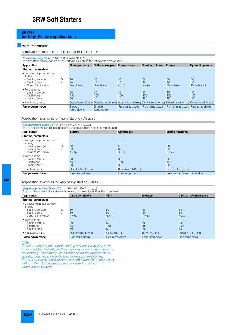
8122019 Arr Estado Solido
httpslidepdfcomreaderfullarr-estado-solido 3040
3RW Soft Starters
3RW44for High-Feature applications
More information
Application examples for normal starting (Class 10)
Application examples for heavy starting (Class 20)
Application examples for very heavy starting (Class 30)
NoteThese tables present sample setting values and device sizesThey are intended only for the purposes of information and arenot binding The setting values depend on the application inquestion and must be optimized during commissioningThe soft starter dimensions should be checked where necessarywith the Win-Soft Starter software or with the help ofTechnical Assistance
Normal starting Class 10 (up to 20 s with 350 I n motor)The soft starter rating can be selected to be as high as the rating of the motor used
Application Conveyor belts Roller conveyors Compressors Small ventilators Pumps Hydraulic pumps
Starting parameters
bull Voltage ramp and currentlimiting- Starting voltage 70 60 50 30 30 30- Starting time s 10 10 10 10 10 10- Current limit value Deactivated Deactivated 4 x I M 4 x I M Deactivated Deactivated
bull Torque ramp- Starting torque 60 50 40 20 10 10- End torque 150 150 150 150 150 150- Starting time 10 10 10 10 10 10
bull Breakaway pulse Deactivated (0 ms) Deactivated (0 ms) Deactivated (0 ms) Deactivated (0 ms) Deactivated (0 ms) Deactivated (0 ms)
Ramp-down mode Smoothramp-down
Smoothramp-down
Free ramp-down Free ramp-down Pump ramp-down Free ramp-down
Heavy starting Class 20 (up to 40 s with 350 I n motor)The soft starter has to be selected one rating class higher than the motor used
Application Stirrers Centrifuges Milling machines
Starting parameters
bull Voltage ramp and currentlimiting- Starting voltage 30 30 30- Starting time s 30 30 30- Current limit value 4 x I M 4 x I M 4 x I M
bull Torque ramp- Starting torque 30 30 30- End torque 150 150 150- Starting time 30 30 30
bull Breakaway pulse Deactivated (0 ms) Deactivated (0 ms) Deactivated (0 ms)
Ramp-down mode Free ramp-down Free ramp-down Free ramp-down or DC braking
Very heavy starting Class 30 (up to 60 s with 350 I n motor)The soft starter has to be selected two rating classes higher than the motor used
Application Large ventilators Mills Breakers Circular sawbandsaws
Starting parameters
bull Voltage ramp and currentlimiting- Starting voltage 30 50 50 30- Starting time s 60 60 60 60- Current limit value 4 x I M 4 x I M 4 x I M 4 x I M
bull Torque ramp- Starting torque 20 50 50 20- End torque 150 150 150 150- Starting time 60 60 60 60
bull Breakaway pulse Deactivated (0 ms) 80 300 ms 80 300 ms Deactivated (0 ms)
Ramp-down mode Free ramp-down Free ramp-down Free ramp-down Free ramp-down
8122019 Arr Estado Solido
httpslidepdfcomreaderfullarr-estado-solido 3140
3RW Soft Starters
3RW44for High-Feature applications
Circuit concept
The SIRIUS 3RW44 soft starters can be operated in two differenttypes of circuit
bull Inline circuitThe controls for isolating and protecting the motor are simplyconnected in series with the soft starter The motor isconnected to the soft starter with three leads
bull Inside-delta circuitThe wiring is similar to that of wye-delta starters The phases ofthe soft starter are connected in series with the individual motorwindings The soft starter then only has to carry the phasecurrent amounting to about 58 of the rated motor current(conductor current)
Comparison of the types of circuit
Inline circuitRated current I e corresponds to the rated motor current I n3 leads to the motor
Inside-delta circuit
Rated current I e corresponds to approx 58 of the rated motorcurrent I n6 leads to the motor (as with wye-delta starters)
Which circuit
Using the inline circuit involves the lowest wiring complexityIf the soft starter to motor connections are long this contactsequence is preferableWith the inside-delta circuit there is double the wiring complexitybut a smaller size of device can be used at the same rating
Thanks to choosing the operational mode between the inline cir-cuit and inside-delta circuit the most favorable solution can al-ways be chosen
The braking function is possible only in the inline circuit
Configuration
The 3RW44 solid-state soft starters are designed for normalstarting In case of heavy starting or increased starting
frequency a larger device must be selectedFor long starting times it is recommended to have a PTC ther-mistor detector in the motor This also applies for the ramp-downmodes smooth ramp-down pump ramp-down and DC brakingbecause during the ramp-down time in these modes an addi-tional current loading applies in contrast to free ramp-down
In the motor feeder between the SIRIUS 3RW soft starter and themotor no capacitive elements are permitted (eg no reactive-power compensation equipment) In addition neither staticsystems for reactive-power compensation nor dynamic PFC(Power Factor Correction) must be operated in parallel duringstarting and ramp-down of the soft starter This is important toprevent faults arising on the compensation equipment andor thesoft starter
All elements of the main circuit (such as fuses and controls)
should be dimensioned for direct starting following the localshort-circuit conditions Fuses switching devices and overloadrelays must be ordered separately
The harmonic component load for starting currents must betaken into consideration for the selection of motor starterprotectors (selection of release)
NoteWhen switching on three-phase current motors voltage dropsnormally will occur with all types of starters (direct starters star- delta starters soft starters) On principle the feeding transformermust be configured such that when starting the motor thevoltage drop must occur within the admissible tolerance Whenthe feeding transformer is designed quite scarce the control vol- tage (being independent of the main voltage) should be sup- plied with a separate circuit in order to prevent the soft starterfrom switching off
Serial PC interface PROFIBUS DP communication moduleand parameterizing and operating software Soft Starter ES
The solid-state 3RW44 soft starters have a PC interface forcommunicating with the Soft Starter ES 2006 Smart software orto be connected to an external operating and monitoring mod-ule When using the optional communication module PROFIBUSthe 3RW44 soft starter can be connected to the PROFIBUS netand can communicate via GSD file or software Soft Starter ES2006 Professional
Manual for SIRIUS 3RW44
Besides containing all important information on planning com-missioning and servicing the manual also contains suggestedcircuits and the technical specifications for all devices
Win-Soft Starter selection and simulation program
With this software you can simulate and select all Siemens softstarters taking into account various parameters such as mainsproperties motor and load data and special applicationrequirements
The software is a valuable tool which makes complicatedlengthy manual calculations for determining the required softstarters superfluous
You can order the CD-ROM under the following order numberOrder No E20001-D1020-P302-V2-7400
More information can be found on the Internet athttpwwwsiemenscomsoftstarter
8122019 Arr Estado Solido
httpslidepdfcomreaderfullarr-estado-solido 3240
3RW Soft Starters
3RW44for High-Feature applications
SIRIUS soft starter training course (SD-SIRIUSO)
Siemens offers a 2-day training course on the SIRIUS solid-statesoft starters to keep customers and own personnel up-to-date on
configuring commissioning and servicing issuesPlease direct enquiries and applications to
AampD PT 4 (Trainings-Center Erlangen)Werner-von-Siemens-Str 65D-91052 ErlangenTelefon ++49 9131 729262Telefax ++49 9131 728172sibrainindustrysiemenscomhttp wwwsiemenscomsitrain
8122019 Arr Estado Solido
httpslidepdfcomreaderfullarr-estado-solido 3340
3RW Soft Starters
Project planning aids
Dimensional drawings
3RW44 2 3RW44 3 and 3RW44 4 for High-Feature applications
TypeDimension(mm)
a b c d e f g h I k l m n o p q
3RW44 2 180 170 37 11 167 100 240 270 180 148 75 153 7 184 66 M6 10 Nm
3RW44 3 180 170 37 17 167 100 240 270 180 148 75 153 7 198 9 M6 10 Nm
3RW44 4 210 210 48 25 190 140 269 298 205 166 16 166 9 230 11 M8 15 Nm
8122019 Arr Estado Solido
httpslidepdfcomreaderfullarr-estado-solido 3440
3RW Soft Starters
Project planning aids
3RW44 5 for High-Feature applications
147
173
195
118
N S B 0_
0 1 6 5 3
261
290
249
162
152
6 2 3
1 0 5
2 5 3
1 6 5
76
44
470
510
1
5 5
2
0Oslash14 40
6 3 8 5
5 9 0
8122019 Arr Estado Solido
httpslidepdfcomreaderfullarr-estado-solido 3540
3RW Soft Starters
Project planning aids
Schematics
1) Permissible values for main and control voltagesee Technical Specifications
3RW44 connection examples for main and control circuits
Main circuit Control circuitPossibility 1a Possibility 1Inline circuit with circuit-breaker and SITOR fuse(semiconductor protection only)
Control by pushbutton
Main circuit
Possibility 1b Possibility 1cInline circuit with full-rangeprotection (line andsemiconductor protection)
Inline circuit with line andSITOR fuse(semiconductor protection only)
Q1
L3L2L1
G1
F3
T1 T2 T3
M1
N S B 0_
0 1 4 9 0 a
L1 L2 L3
V1U1 W1
MPE 3~
3NPE 400 V AC 50 Hz
(optionalsemiconductorprotection fuse)
13 14 23 24 33 34 95 9896 +
T1 T2IN4IN3IN2IN1L-L+A1
A2
NPE
PE
G1
F2
NSB0_01494a
S t a r t
S 2
R e s e t S
3
StopS1
L1
On periodGrouperror
N o a c t i o n
N o a c t i o n
Noaction
PTC type Aor
Thermoclick
Noaction
1NPE 230 V AC 50 Hz
M o t o r o
n r i g h t
P S
1
1)
8122019 Arr Estado Solido
httpslidepdfcomreaderfullarr-estado-solido 3640
3RW Soft Starters
Project planning aids
1) Permissible values for main and control voltagesee Technical Specifications
2) Caution Risk of restartingThe start command (eg from the PLC) must be reset prior to a resetcommand because a new automatic restart will take place automaticallyif a start command is active after the reset command This appliesespecially in case of motor protection trippingFor safety reasons we recommend incorporating the group error output(terminals 95 and 96) in the controller
Main circuit Control circuit
Possibility 2 Possibility 2Inline circuit with main contactor Control of a main contactor and control by means of PLC
Q1
L3L2L1
G1
K1
F3
L1 L2 L3
T1 T2 T3
M1
N S B 0_
0 1 4 9 5 a
V1U1 W1
MPE 3~
1)
(optionalsemiconductorprotection)
(optional linecontactor if floatingswitching of themotor is planned)
3NPE 400 V AC 50 Hz
13 14 23 24 33 34 95 9896+
T1 T2IN4IN3IN2IN1L-L+A1
A2
NPE
PE
G1
K1NSB0_01496a
F2+24 V DC
M
L1 1NPE AC 230 V 50 Hz1)
Switch-on duration
M o t o r r i g h t
T r i p R e s e t
PLC outputs PLC inputs
N o a c t i o n
N o a c t i o n
No action No action
Group error
PTC type A Thermoclick
(optional line contactorif floating switchingof the motor is planned)
P S 1
ResetStart 2)
8122019 Arr Estado Solido
httpslidepdfcomreaderfullarr-estado-solido 3740
3RW Soft Starters
Project planning aids
1) Permissible values for main and control voltagesee Technical Specifications
2) Caution Risk of restartingThe start command (eg from the PLC) must be reset prior to a resetcommand because a new automatic restart will take place automaticallyif a start command is active after the reset command This applies espe-cially in case of motor protection trippingFor safety reasons we recommend incorporating the group error output(terminals 95 and 96) in the controller
3) If the ramp-down function Combined braking is selected no brakingcontactor is requiredIf the ramp-down function DC braking is selected a braking contactormust be used in addition Type see Fuse Coordination (inline circuit) onpages 621 to 623For applications with large centrifugal masses (J Load gt J Motor) werecommend the function DC brakingThe output 2 must be switched over to DC braking contactor
4) Auxiliary relay K4 egLZXRT4A4T30 (230 V AC rated control supply voltage)LZXRT4A4S15 (115 V AC rated control supply voltage)
Main circuit Control circuit
Possibility 3a Possibility 3aInline circuit with ramp-down function DC braking3)
(for device types 3RW44 22 to 3RW44 25)Control of the braking contactor3)
Main circuit Control circuit
Possibility 3b Possibility 3bInline circuit with ramp-down function DC braking3)
(for device types 3RW44 26 to 3RW44 47)Control of the braking contactor3)
Q1
L3L2
G1
F3
T1 T2 T3
M1
N S B 0_
0 1 5 0 1 a
L1 L2 L3
V1U1 W1
M
K2 K2 K2
PE 3~
1)
2
(optionalsemi-conductorprotection)
L1 3NPE 400 V AC 50 Hz
13 14 23 24 33 34 95 9896 +
T1 T2IN4IN3IN2IN1L-L+A1
A2
NPE
PEG1
K2NSB0_01502
R e s e t
M Start Reset
+24 V DC
K2
F2
1)
2)
No action Group error
N o a c t i o n
N o a c t i o n
On period
PLC output
PTC type Aor
Thermoclick
L1 1NPE 230 V AC 50 Hz
DC braking contactor 3)
K2 K33 3
G1
F3
T1 T2 T3
M1
N S B 0_
0 1
5 0 3 a
L1 L2 L3
V1U1 W1
MPE 3~
Q1
L3L2
1)
(optionalsemi-conductorprotection)
L1 3NPE 400 V AC 50 Hz
13 14 23 24 33 34 95 9896 +
T1 T2IN4IN3IN2IN1L-L+A1
A2
NPE
PE
G1
K4
NSB0_01504
R e s e t
K4 K4
K3 K2
K2 K3
+24 V DC
M Start Reset
F2
1)
2)
4)
PLC output
No action Group error
N o a c t i o n
N o a c t i o n
ON period
PTC type Aor
Thermoclick
M o t o r o n r i g h t
L1 1NPE 230 V AC 50 Hz
DC braking contactor 3)
8122019 Arr Estado Solido
httpslidepdfcomreaderfullarr-estado-solido 3840
3RW Soft Starters
Notes
1) Permissible values for main and control voltagesee Technical Specifications
2) Caution Risk of restartingThe start command (eg from the PLC) must be reset prior to a resetcommand because a new automatic restart will take place automaticallyif a start command is active after the reset command This appliesespecially in case of motor protection trippingFor safety reasons we recommend incorporating the group error output(terminals 95 and 96) in the controller
Main circuit Control circuit
Possibility 4a Possibility 4b Possibility 4Inside-delta circuit Change of direction of rotation for
inside-delta circuitControl by means of PLC
13 14 23 24 33 34 95 9896+
T1 T2IN4IN3IN2IN1L-L+A1
A2
NPE
PEG1
NSB0_01498a
+24 V DC
M
F2
L1 1NPE AC 230 V 50 Hz1)
2)
R e s e t
Switch-onduration
No action
Group error
N o a c t i o n
N o a c t i o n
No action
PTC type A orThermoclick
M o t o r r i g h t
PLC outputs PLC inputs
Start Reset
7
8122019 Arr Estado Solido
httpslidepdfcomreaderfullarr-estado-solido 3940
Appendix
Conditions of sale and delivery
Terms and Conditions of Sale and Delivery
By using this catalog you can acquire hardware and softwareproducts described therein from the Siemens AG subject to the
following terms Please note The scope the quality and the con-ditions for supplies and services including software productsby any Siemens entity having a registered office outside of Ger-many shall be subject exclusively to the General Terms andConditions of the respective Siemens entity
For customers with a seat or registered office in theFederal Republic of Germany
The bdquoGeneral Terms of Paymentldquo as well as the bdquoGeneral Condi-tions for the Supply of Products and Services of the Electricaland Electronics Industryldquo shall apply
For software products the bdquoGeneral License Conditions for Soft-ware Products for Automation and Drives for Customers with aSeat or registered Office in Germanyldquo shall apply
For customers with a seat or registered office outside of
Germany The bdquoGeneral Terms of Paymentldquo as well as the bdquoGeneral Condi-tions for Supplies of Siemens Automation and Drives for Cus-tomers with a Seat or registered Office outside of Germanyldquo shallapply
For software products the bdquoGeneral License Conditions for Soft-ware Products for Automation and Drives for Customers with aSeat or registered Office outside of Germanyldquo shall apply
General
The prices are in 991404 (Euro) ex works exclusive packaging
The sales tax (value added tax) is not included in the pricesIt shall be debited separately at the respective rate according tothe applicable legal regulations
In addition to the prices of products which include silver plump
aluminum andor copper surcharges may be calculated if therespective limits of the notes are exceeded The respective note(eg source German newspaper bdquoHandesblattldquo in categorybdquodeutsche Edelmetalleldquo and bdquoMetallverarbeiterldquo) for silver (bdquover-arbeitetes Silberldquo) plump (bdquoBlei in Kabelnldquo) aluminum (bdquoAlumin-ium in Kabelnldquo) and copper (bdquoElektrolytkupferldquo bdquoDEL-Notizldquo) re-spectively of the day the order or rather the on call order isreceived is decisive for the calculation of the surcharges
Surcharges of copper shall be calculated for Drives at a note(bdquoDEL-Notizldquo) above EUR 22500 100 Kg and for chokes trans-formers above EUR 15000 100 kg
Surcharges shall be charged based on the quantities of the ma-terials which are contained in the relevant products
Prices are subject to change without prior notice We will debitthe prices valid at the time of delivery
The dimensions are in mm In Germany according to the Ger-man law on units in measuring technology data in inches onlyapply to devices for export
Illustrations are not binding
Insofar as there are no remarks on the corresponding pages- especially with regard to data dimensions and weights given -these are subject to change without prior notice
Comprehensive Terms and Conditions of Sale and Delivery areavailable free of charge from your local Siemens business officeunder the following Order Nos
bull 6ZB5310-0KR30-0BA0(for customers based in the Federal Republic of Germany)
bull 6ZB5310-0KS53-0BA0(for customers based outside of theFederal Republic ofGermany)
or download them from the Internethttpwwwsiemenscomautomationmall (Germany AampD Mall Online-Help System)
Export regulations
The products listed in this catalog price list may be subject toEuropean German andor US export regulations
Therefore any export requiring a license is subject to approvalby the competent authorities
According to current provisions the following export regulations
must be observed with respect to the products featured in thiscatalog price list
Even without a label or with an ldquoAL Nldquo or ldquoECCN Nldquo authoriza-tion may be required due to the final destination and purpose forwhich the goods are to be used
The deciding factors are the AL or ECCN export authorizationindicated on order confirmations delivery notes and invoices
Errors excepted and subject to change without prior notice
AampDVuLEn 060306
AL Number of the German Export List
Products marked other than ldquoNldquo require an exportlicenseIn the case of software products the export des-ignations of the relevant data medium must alsobe generally adhered to
Goods labeled with an ldquoAL not equal to Nldquo aresubject to a European or German export authori-zation when being exported out of the EU
ECCN Export Control Classification Number
Products marked other than ldquoNldquo are subject to a
reexport license to specific countriesIn the case of software products the exportdesignations of the relevant data medium mustalso be generally adhered to
Goods labeled with an ldquoECCN not equal to Nldquo aresubject to a US re-export authorization
_ _ _ _
8122019 Arr Estado Solido
httpslidepdfcomreaderfullarr-estado-solido 4040
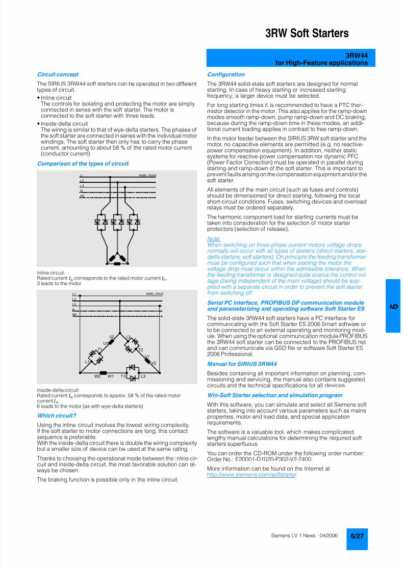
8122019 Arr Estado Solido
httpslidepdfcomreaderfullarr-estado-solido 3140
3RW Soft Starters
3RW44for High-Feature applications
Circuit concept
The SIRIUS 3RW44 soft starters can be operated in two differenttypes of circuit
bull Inline circuitThe controls for isolating and protecting the motor are simplyconnected in series with the soft starter The motor isconnected to the soft starter with three leads
bull Inside-delta circuitThe wiring is similar to that of wye-delta starters The phases ofthe soft starter are connected in series with the individual motorwindings The soft starter then only has to carry the phasecurrent amounting to about 58 of the rated motor current(conductor current)
Comparison of the types of circuit
Inline circuitRated current I e corresponds to the rated motor current I n3 leads to the motor
Inside-delta circuit
Rated current I e corresponds to approx 58 of the rated motorcurrent I n6 leads to the motor (as with wye-delta starters)
Which circuit
Using the inline circuit involves the lowest wiring complexityIf the soft starter to motor connections are long this contactsequence is preferableWith the inside-delta circuit there is double the wiring complexitybut a smaller size of device can be used at the same rating
Thanks to choosing the operational mode between the inline cir-cuit and inside-delta circuit the most favorable solution can al-ways be chosen
The braking function is possible only in the inline circuit
Configuration
The 3RW44 solid-state soft starters are designed for normalstarting In case of heavy starting or increased starting
frequency a larger device must be selectedFor long starting times it is recommended to have a PTC ther-mistor detector in the motor This also applies for the ramp-downmodes smooth ramp-down pump ramp-down and DC brakingbecause during the ramp-down time in these modes an addi-tional current loading applies in contrast to free ramp-down
In the motor feeder between the SIRIUS 3RW soft starter and themotor no capacitive elements are permitted (eg no reactive-power compensation equipment) In addition neither staticsystems for reactive-power compensation nor dynamic PFC(Power Factor Correction) must be operated in parallel duringstarting and ramp-down of the soft starter This is important toprevent faults arising on the compensation equipment andor thesoft starter
All elements of the main circuit (such as fuses and controls)
should be dimensioned for direct starting following the localshort-circuit conditions Fuses switching devices and overloadrelays must be ordered separately
The harmonic component load for starting currents must betaken into consideration for the selection of motor starterprotectors (selection of release)
NoteWhen switching on three-phase current motors voltage dropsnormally will occur with all types of starters (direct starters star- delta starters soft starters) On principle the feeding transformermust be configured such that when starting the motor thevoltage drop must occur within the admissible tolerance Whenthe feeding transformer is designed quite scarce the control vol- tage (being independent of the main voltage) should be sup- plied with a separate circuit in order to prevent the soft starterfrom switching off
Serial PC interface PROFIBUS DP communication moduleand parameterizing and operating software Soft Starter ES
The solid-state 3RW44 soft starters have a PC interface forcommunicating with the Soft Starter ES 2006 Smart software orto be connected to an external operating and monitoring mod-ule When using the optional communication module PROFIBUSthe 3RW44 soft starter can be connected to the PROFIBUS netand can communicate via GSD file or software Soft Starter ES2006 Professional
Manual for SIRIUS 3RW44
Besides containing all important information on planning com-missioning and servicing the manual also contains suggestedcircuits and the technical specifications for all devices
Win-Soft Starter selection and simulation program
With this software you can simulate and select all Siemens softstarters taking into account various parameters such as mainsproperties motor and load data and special applicationrequirements
The software is a valuable tool which makes complicatedlengthy manual calculations for determining the required softstarters superfluous
You can order the CD-ROM under the following order numberOrder No E20001-D1020-P302-V2-7400
More information can be found on the Internet athttpwwwsiemenscomsoftstarter
8122019 Arr Estado Solido
httpslidepdfcomreaderfullarr-estado-solido 3240
3RW Soft Starters
3RW44for High-Feature applications
SIRIUS soft starter training course (SD-SIRIUSO)
Siemens offers a 2-day training course on the SIRIUS solid-statesoft starters to keep customers and own personnel up-to-date on
configuring commissioning and servicing issuesPlease direct enquiries and applications to
AampD PT 4 (Trainings-Center Erlangen)Werner-von-Siemens-Str 65D-91052 ErlangenTelefon ++49 9131 729262Telefax ++49 9131 728172sibrainindustrysiemenscomhttp wwwsiemenscomsitrain
8122019 Arr Estado Solido
httpslidepdfcomreaderfullarr-estado-solido 3340
3RW Soft Starters
Project planning aids
Dimensional drawings
3RW44 2 3RW44 3 and 3RW44 4 for High-Feature applications
TypeDimension(mm)
a b c d e f g h I k l m n o p q
3RW44 2 180 170 37 11 167 100 240 270 180 148 75 153 7 184 66 M6 10 Nm
3RW44 3 180 170 37 17 167 100 240 270 180 148 75 153 7 198 9 M6 10 Nm
3RW44 4 210 210 48 25 190 140 269 298 205 166 16 166 9 230 11 M8 15 Nm
8122019 Arr Estado Solido
httpslidepdfcomreaderfullarr-estado-solido 3440
3RW Soft Starters
Project planning aids
3RW44 5 for High-Feature applications
147
173
195
118
N S B 0_
0 1 6 5 3
261
290
249
162
152
6 2 3
1 0 5
2 5 3
1 6 5
76
44
470
510
1
5 5
2
0Oslash14 40
6 3 8 5
5 9 0
8122019 Arr Estado Solido
httpslidepdfcomreaderfullarr-estado-solido 3540
3RW Soft Starters
Project planning aids
Schematics
1) Permissible values for main and control voltagesee Technical Specifications
3RW44 connection examples for main and control circuits
Main circuit Control circuitPossibility 1a Possibility 1Inline circuit with circuit-breaker and SITOR fuse(semiconductor protection only)
Control by pushbutton
Main circuit
Possibility 1b Possibility 1cInline circuit with full-rangeprotection (line andsemiconductor protection)
Inline circuit with line andSITOR fuse(semiconductor protection only)
Q1
L3L2L1
G1
F3
T1 T2 T3
M1
N S B 0_
0 1 4 9 0 a
L1 L2 L3
V1U1 W1
MPE 3~
3NPE 400 V AC 50 Hz
(optionalsemiconductorprotection fuse)
13 14 23 24 33 34 95 9896 +
T1 T2IN4IN3IN2IN1L-L+A1
A2
NPE
PE
G1
F2
NSB0_01494a
S t a r t
S 2
R e s e t S
3
StopS1
L1
On periodGrouperror
N o a c t i o n
N o a c t i o n
Noaction
PTC type Aor
Thermoclick
Noaction
1NPE 230 V AC 50 Hz
M o t o r o
n r i g h t
P S
1
1)
8122019 Arr Estado Solido
httpslidepdfcomreaderfullarr-estado-solido 3640
3RW Soft Starters
Project planning aids
1) Permissible values for main and control voltagesee Technical Specifications
2) Caution Risk of restartingThe start command (eg from the PLC) must be reset prior to a resetcommand because a new automatic restart will take place automaticallyif a start command is active after the reset command This appliesespecially in case of motor protection trippingFor safety reasons we recommend incorporating the group error output(terminals 95 and 96) in the controller
Main circuit Control circuit
Possibility 2 Possibility 2Inline circuit with main contactor Control of a main contactor and control by means of PLC
Q1
L3L2L1
G1
K1
F3
L1 L2 L3
T1 T2 T3
M1
N S B 0_
0 1 4 9 5 a
V1U1 W1
MPE 3~
1)
(optionalsemiconductorprotection)
(optional linecontactor if floatingswitching of themotor is planned)
3NPE 400 V AC 50 Hz
13 14 23 24 33 34 95 9896+
T1 T2IN4IN3IN2IN1L-L+A1
A2
NPE
PE
G1
K1NSB0_01496a
F2+24 V DC
M
L1 1NPE AC 230 V 50 Hz1)
Switch-on duration
M o t o r r i g h t
T r i p R e s e t
PLC outputs PLC inputs
N o a c t i o n
N o a c t i o n
No action No action
Group error
PTC type A Thermoclick
(optional line contactorif floating switchingof the motor is planned)
P S 1
ResetStart 2)
8122019 Arr Estado Solido
httpslidepdfcomreaderfullarr-estado-solido 3740
3RW Soft Starters
Project planning aids
1) Permissible values for main and control voltagesee Technical Specifications
2) Caution Risk of restartingThe start command (eg from the PLC) must be reset prior to a resetcommand because a new automatic restart will take place automaticallyif a start command is active after the reset command This applies espe-cially in case of motor protection trippingFor safety reasons we recommend incorporating the group error output(terminals 95 and 96) in the controller
3) If the ramp-down function Combined braking is selected no brakingcontactor is requiredIf the ramp-down function DC braking is selected a braking contactormust be used in addition Type see Fuse Coordination (inline circuit) onpages 621 to 623For applications with large centrifugal masses (J Load gt J Motor) werecommend the function DC brakingThe output 2 must be switched over to DC braking contactor
4) Auxiliary relay K4 egLZXRT4A4T30 (230 V AC rated control supply voltage)LZXRT4A4S15 (115 V AC rated control supply voltage)
Main circuit Control circuit
Possibility 3a Possibility 3aInline circuit with ramp-down function DC braking3)
(for device types 3RW44 22 to 3RW44 25)Control of the braking contactor3)
Main circuit Control circuit
Possibility 3b Possibility 3bInline circuit with ramp-down function DC braking3)
(for device types 3RW44 26 to 3RW44 47)Control of the braking contactor3)
Q1
L3L2
G1
F3
T1 T2 T3
M1
N S B 0_
0 1 5 0 1 a
L1 L2 L3
V1U1 W1
M
K2 K2 K2
PE 3~
1)
2
(optionalsemi-conductorprotection)
L1 3NPE 400 V AC 50 Hz
13 14 23 24 33 34 95 9896 +
T1 T2IN4IN3IN2IN1L-L+A1
A2
NPE
PEG1
K2NSB0_01502
R e s e t
M Start Reset
+24 V DC
K2
F2
1)
2)
No action Group error
N o a c t i o n
N o a c t i o n
On period
PLC output
PTC type Aor
Thermoclick
L1 1NPE 230 V AC 50 Hz
DC braking contactor 3)
K2 K33 3
G1
F3
T1 T2 T3
M1
N S B 0_
0 1
5 0 3 a
L1 L2 L3
V1U1 W1
MPE 3~
Q1
L3L2
1)
(optionalsemi-conductorprotection)
L1 3NPE 400 V AC 50 Hz
13 14 23 24 33 34 95 9896 +
T1 T2IN4IN3IN2IN1L-L+A1
A2
NPE
PE
G1
K4
NSB0_01504
R e s e t
K4 K4
K3 K2
K2 K3
+24 V DC
M Start Reset
F2
1)
2)
4)
PLC output
No action Group error
N o a c t i o n
N o a c t i o n
ON period
PTC type Aor
Thermoclick
M o t o r o n r i g h t
L1 1NPE 230 V AC 50 Hz
DC braking contactor 3)
8122019 Arr Estado Solido
httpslidepdfcomreaderfullarr-estado-solido 3840
3RW Soft Starters
Notes
1) Permissible values for main and control voltagesee Technical Specifications
2) Caution Risk of restartingThe start command (eg from the PLC) must be reset prior to a resetcommand because a new automatic restart will take place automaticallyif a start command is active after the reset command This appliesespecially in case of motor protection trippingFor safety reasons we recommend incorporating the group error output(terminals 95 and 96) in the controller
Main circuit Control circuit
Possibility 4a Possibility 4b Possibility 4Inside-delta circuit Change of direction of rotation for
inside-delta circuitControl by means of PLC
13 14 23 24 33 34 95 9896+
T1 T2IN4IN3IN2IN1L-L+A1
A2
NPE
PEG1
NSB0_01498a
+24 V DC
M
F2
L1 1NPE AC 230 V 50 Hz1)
2)
R e s e t
Switch-onduration
No action
Group error
N o a c t i o n
N o a c t i o n
No action
PTC type A orThermoclick
M o t o r r i g h t
PLC outputs PLC inputs
Start Reset
7
8122019 Arr Estado Solido
httpslidepdfcomreaderfullarr-estado-solido 3940
Appendix
Conditions of sale and delivery
Terms and Conditions of Sale and Delivery
By using this catalog you can acquire hardware and softwareproducts described therein from the Siemens AG subject to the
following terms Please note The scope the quality and the con-ditions for supplies and services including software productsby any Siemens entity having a registered office outside of Ger-many shall be subject exclusively to the General Terms andConditions of the respective Siemens entity
For customers with a seat or registered office in theFederal Republic of Germany
The bdquoGeneral Terms of Paymentldquo as well as the bdquoGeneral Condi-tions for the Supply of Products and Services of the Electricaland Electronics Industryldquo shall apply
For software products the bdquoGeneral License Conditions for Soft-ware Products for Automation and Drives for Customers with aSeat or registered Office in Germanyldquo shall apply
For customers with a seat or registered office outside of
Germany The bdquoGeneral Terms of Paymentldquo as well as the bdquoGeneral Condi-tions for Supplies of Siemens Automation and Drives for Cus-tomers with a Seat or registered Office outside of Germanyldquo shallapply
For software products the bdquoGeneral License Conditions for Soft-ware Products for Automation and Drives for Customers with aSeat or registered Office outside of Germanyldquo shall apply
General
The prices are in 991404 (Euro) ex works exclusive packaging
The sales tax (value added tax) is not included in the pricesIt shall be debited separately at the respective rate according tothe applicable legal regulations
In addition to the prices of products which include silver plump
aluminum andor copper surcharges may be calculated if therespective limits of the notes are exceeded The respective note(eg source German newspaper bdquoHandesblattldquo in categorybdquodeutsche Edelmetalleldquo and bdquoMetallverarbeiterldquo) for silver (bdquover-arbeitetes Silberldquo) plump (bdquoBlei in Kabelnldquo) aluminum (bdquoAlumin-ium in Kabelnldquo) and copper (bdquoElektrolytkupferldquo bdquoDEL-Notizldquo) re-spectively of the day the order or rather the on call order isreceived is decisive for the calculation of the surcharges
Surcharges of copper shall be calculated for Drives at a note(bdquoDEL-Notizldquo) above EUR 22500 100 Kg and for chokes trans-formers above EUR 15000 100 kg
Surcharges shall be charged based on the quantities of the ma-terials which are contained in the relevant products
Prices are subject to change without prior notice We will debitthe prices valid at the time of delivery
The dimensions are in mm In Germany according to the Ger-man law on units in measuring technology data in inches onlyapply to devices for export
Illustrations are not binding
Insofar as there are no remarks on the corresponding pages- especially with regard to data dimensions and weights given -these are subject to change without prior notice
Comprehensive Terms and Conditions of Sale and Delivery areavailable free of charge from your local Siemens business officeunder the following Order Nos
bull 6ZB5310-0KR30-0BA0(for customers based in the Federal Republic of Germany)
bull 6ZB5310-0KS53-0BA0(for customers based outside of theFederal Republic ofGermany)
or download them from the Internethttpwwwsiemenscomautomationmall (Germany AampD Mall Online-Help System)
Export regulations
The products listed in this catalog price list may be subject toEuropean German andor US export regulations
Therefore any export requiring a license is subject to approvalby the competent authorities
According to current provisions the following export regulations
must be observed with respect to the products featured in thiscatalog price list
Even without a label or with an ldquoAL Nldquo or ldquoECCN Nldquo authoriza-tion may be required due to the final destination and purpose forwhich the goods are to be used
The deciding factors are the AL or ECCN export authorizationindicated on order confirmations delivery notes and invoices
Errors excepted and subject to change without prior notice
AampDVuLEn 060306
AL Number of the German Export List
Products marked other than ldquoNldquo require an exportlicenseIn the case of software products the export des-ignations of the relevant data medium must alsobe generally adhered to
Goods labeled with an ldquoAL not equal to Nldquo aresubject to a European or German export authori-zation when being exported out of the EU
ECCN Export Control Classification Number
Products marked other than ldquoNldquo are subject to a
reexport license to specific countriesIn the case of software products the exportdesignations of the relevant data medium mustalso be generally adhered to
Goods labeled with an ldquoECCN not equal to Nldquo aresubject to a US re-export authorization
_ _ _ _
8122019 Arr Estado Solido
httpslidepdfcomreaderfullarr-estado-solido 4040
8122019 Arr Estado Solido
httpslidepdfcomreaderfullarr-estado-solido 3240
3RW Soft Starters
3RW44for High-Feature applications
SIRIUS soft starter training course (SD-SIRIUSO)
Siemens offers a 2-day training course on the SIRIUS solid-statesoft starters to keep customers and own personnel up-to-date on
configuring commissioning and servicing issuesPlease direct enquiries and applications to
AampD PT 4 (Trainings-Center Erlangen)Werner-von-Siemens-Str 65D-91052 ErlangenTelefon ++49 9131 729262Telefax ++49 9131 728172sibrainindustrysiemenscomhttp wwwsiemenscomsitrain
8122019 Arr Estado Solido
httpslidepdfcomreaderfullarr-estado-solido 3340
3RW Soft Starters
Project planning aids
Dimensional drawings
3RW44 2 3RW44 3 and 3RW44 4 for High-Feature applications
TypeDimension(mm)
a b c d e f g h I k l m n o p q
3RW44 2 180 170 37 11 167 100 240 270 180 148 75 153 7 184 66 M6 10 Nm
3RW44 3 180 170 37 17 167 100 240 270 180 148 75 153 7 198 9 M6 10 Nm
3RW44 4 210 210 48 25 190 140 269 298 205 166 16 166 9 230 11 M8 15 Nm
8122019 Arr Estado Solido
httpslidepdfcomreaderfullarr-estado-solido 3440
3RW Soft Starters
Project planning aids
3RW44 5 for High-Feature applications
147
173
195
118
N S B 0_
0 1 6 5 3
261
290
249
162
152
6 2 3
1 0 5
2 5 3
1 6 5
76
44
470
510
1
5 5
2
0Oslash14 40
6 3 8 5
5 9 0
8122019 Arr Estado Solido
httpslidepdfcomreaderfullarr-estado-solido 3540
3RW Soft Starters
Project planning aids
Schematics
1) Permissible values for main and control voltagesee Technical Specifications
3RW44 connection examples for main and control circuits
Main circuit Control circuitPossibility 1a Possibility 1Inline circuit with circuit-breaker and SITOR fuse(semiconductor protection only)
Control by pushbutton
Main circuit
Possibility 1b Possibility 1cInline circuit with full-rangeprotection (line andsemiconductor protection)
Inline circuit with line andSITOR fuse(semiconductor protection only)
Q1
L3L2L1
G1
F3
T1 T2 T3
M1
N S B 0_
0 1 4 9 0 a
L1 L2 L3
V1U1 W1
MPE 3~
3NPE 400 V AC 50 Hz
(optionalsemiconductorprotection fuse)
13 14 23 24 33 34 95 9896 +
T1 T2IN4IN3IN2IN1L-L+A1
A2
NPE
PE
G1
F2
NSB0_01494a
S t a r t
S 2
R e s e t S
3
StopS1
L1
On periodGrouperror
N o a c t i o n
N o a c t i o n
Noaction
PTC type Aor
Thermoclick
Noaction
1NPE 230 V AC 50 Hz
M o t o r o
n r i g h t
P S
1
1)
8122019 Arr Estado Solido
httpslidepdfcomreaderfullarr-estado-solido 3640
3RW Soft Starters
Project planning aids
1) Permissible values for main and control voltagesee Technical Specifications
2) Caution Risk of restartingThe start command (eg from the PLC) must be reset prior to a resetcommand because a new automatic restart will take place automaticallyif a start command is active after the reset command This appliesespecially in case of motor protection trippingFor safety reasons we recommend incorporating the group error output(terminals 95 and 96) in the controller
Main circuit Control circuit
Possibility 2 Possibility 2Inline circuit with main contactor Control of a main contactor and control by means of PLC
Q1
L3L2L1
G1
K1
F3
L1 L2 L3
T1 T2 T3
M1
N S B 0_
0 1 4 9 5 a
V1U1 W1
MPE 3~
1)
(optionalsemiconductorprotection)
(optional linecontactor if floatingswitching of themotor is planned)
3NPE 400 V AC 50 Hz
13 14 23 24 33 34 95 9896+
T1 T2IN4IN3IN2IN1L-L+A1
A2
NPE
PE
G1
K1NSB0_01496a
F2+24 V DC
M
L1 1NPE AC 230 V 50 Hz1)
Switch-on duration
M o t o r r i g h t
T r i p R e s e t
PLC outputs PLC inputs
N o a c t i o n
N o a c t i o n
No action No action
Group error
PTC type A Thermoclick
(optional line contactorif floating switchingof the motor is planned)
P S 1
ResetStart 2)
8122019 Arr Estado Solido
httpslidepdfcomreaderfullarr-estado-solido 3740
3RW Soft Starters
Project planning aids
1) Permissible values for main and control voltagesee Technical Specifications
2) Caution Risk of restartingThe start command (eg from the PLC) must be reset prior to a resetcommand because a new automatic restart will take place automaticallyif a start command is active after the reset command This applies espe-cially in case of motor protection trippingFor safety reasons we recommend incorporating the group error output(terminals 95 and 96) in the controller
3) If the ramp-down function Combined braking is selected no brakingcontactor is requiredIf the ramp-down function DC braking is selected a braking contactormust be used in addition Type see Fuse Coordination (inline circuit) onpages 621 to 623For applications with large centrifugal masses (J Load gt J Motor) werecommend the function DC brakingThe output 2 must be switched over to DC braking contactor
4) Auxiliary relay K4 egLZXRT4A4T30 (230 V AC rated control supply voltage)LZXRT4A4S15 (115 V AC rated control supply voltage)
Main circuit Control circuit
Possibility 3a Possibility 3aInline circuit with ramp-down function DC braking3)
(for device types 3RW44 22 to 3RW44 25)Control of the braking contactor3)
Main circuit Control circuit
Possibility 3b Possibility 3bInline circuit with ramp-down function DC braking3)
(for device types 3RW44 26 to 3RW44 47)Control of the braking contactor3)
Q1
L3L2
G1
F3
T1 T2 T3
M1
N S B 0_
0 1 5 0 1 a
L1 L2 L3
V1U1 W1
M
K2 K2 K2
PE 3~
1)
2
(optionalsemi-conductorprotection)
L1 3NPE 400 V AC 50 Hz
13 14 23 24 33 34 95 9896 +
T1 T2IN4IN3IN2IN1L-L+A1
A2
NPE
PEG1
K2NSB0_01502
R e s e t
M Start Reset
+24 V DC
K2
F2
1)
2)
No action Group error
N o a c t i o n
N o a c t i o n
On period
PLC output
PTC type Aor
Thermoclick
L1 1NPE 230 V AC 50 Hz
DC braking contactor 3)
K2 K33 3
G1
F3
T1 T2 T3
M1
N S B 0_
0 1
5 0 3 a
L1 L2 L3
V1U1 W1
MPE 3~
Q1
L3L2
1)
(optionalsemi-conductorprotection)
L1 3NPE 400 V AC 50 Hz
13 14 23 24 33 34 95 9896 +
T1 T2IN4IN3IN2IN1L-L+A1
A2
NPE
PE
G1
K4
NSB0_01504
R e s e t
K4 K4
K3 K2
K2 K3
+24 V DC
M Start Reset
F2
1)
2)
4)
PLC output
No action Group error
N o a c t i o n
N o a c t i o n
ON period
PTC type Aor
Thermoclick
M o t o r o n r i g h t
L1 1NPE 230 V AC 50 Hz
DC braking contactor 3)
8122019 Arr Estado Solido
httpslidepdfcomreaderfullarr-estado-solido 3840
3RW Soft Starters
Notes
1) Permissible values for main and control voltagesee Technical Specifications
2) Caution Risk of restartingThe start command (eg from the PLC) must be reset prior to a resetcommand because a new automatic restart will take place automaticallyif a start command is active after the reset command This appliesespecially in case of motor protection trippingFor safety reasons we recommend incorporating the group error output(terminals 95 and 96) in the controller
Main circuit Control circuit
Possibility 4a Possibility 4b Possibility 4Inside-delta circuit Change of direction of rotation for
inside-delta circuitControl by means of PLC
13 14 23 24 33 34 95 9896+
T1 T2IN4IN3IN2IN1L-L+A1
A2
NPE
PEG1
NSB0_01498a
+24 V DC
M
F2
L1 1NPE AC 230 V 50 Hz1)
2)
R e s e t
Switch-onduration
No action
Group error
N o a c t i o n
N o a c t i o n
No action
PTC type A orThermoclick
M o t o r r i g h t
PLC outputs PLC inputs
Start Reset
7
8122019 Arr Estado Solido
httpslidepdfcomreaderfullarr-estado-solido 3940
Appendix
Conditions of sale and delivery
Terms and Conditions of Sale and Delivery
By using this catalog you can acquire hardware and softwareproducts described therein from the Siemens AG subject to the
following terms Please note The scope the quality and the con-ditions for supplies and services including software productsby any Siemens entity having a registered office outside of Ger-many shall be subject exclusively to the General Terms andConditions of the respective Siemens entity
For customers with a seat or registered office in theFederal Republic of Germany
The bdquoGeneral Terms of Paymentldquo as well as the bdquoGeneral Condi-tions for the Supply of Products and Services of the Electricaland Electronics Industryldquo shall apply
For software products the bdquoGeneral License Conditions for Soft-ware Products for Automation and Drives for Customers with aSeat or registered Office in Germanyldquo shall apply
For customers with a seat or registered office outside of
Germany The bdquoGeneral Terms of Paymentldquo as well as the bdquoGeneral Condi-tions for Supplies of Siemens Automation and Drives for Cus-tomers with a Seat or registered Office outside of Germanyldquo shallapply
For software products the bdquoGeneral License Conditions for Soft-ware Products for Automation and Drives for Customers with aSeat or registered Office outside of Germanyldquo shall apply
General
The prices are in 991404 (Euro) ex works exclusive packaging
The sales tax (value added tax) is not included in the pricesIt shall be debited separately at the respective rate according tothe applicable legal regulations
In addition to the prices of products which include silver plump
aluminum andor copper surcharges may be calculated if therespective limits of the notes are exceeded The respective note(eg source German newspaper bdquoHandesblattldquo in categorybdquodeutsche Edelmetalleldquo and bdquoMetallverarbeiterldquo) for silver (bdquover-arbeitetes Silberldquo) plump (bdquoBlei in Kabelnldquo) aluminum (bdquoAlumin-ium in Kabelnldquo) and copper (bdquoElektrolytkupferldquo bdquoDEL-Notizldquo) re-spectively of the day the order or rather the on call order isreceived is decisive for the calculation of the surcharges
Surcharges of copper shall be calculated for Drives at a note(bdquoDEL-Notizldquo) above EUR 22500 100 Kg and for chokes trans-formers above EUR 15000 100 kg
Surcharges shall be charged based on the quantities of the ma-terials which are contained in the relevant products
Prices are subject to change without prior notice We will debitthe prices valid at the time of delivery
The dimensions are in mm In Germany according to the Ger-man law on units in measuring technology data in inches onlyapply to devices for export
Illustrations are not binding
Insofar as there are no remarks on the corresponding pages- especially with regard to data dimensions and weights given -these are subject to change without prior notice
Comprehensive Terms and Conditions of Sale and Delivery areavailable free of charge from your local Siemens business officeunder the following Order Nos
bull 6ZB5310-0KR30-0BA0(for customers based in the Federal Republic of Germany)
bull 6ZB5310-0KS53-0BA0(for customers based outside of theFederal Republic ofGermany)
or download them from the Internethttpwwwsiemenscomautomationmall (Germany AampD Mall Online-Help System)
Export regulations
The products listed in this catalog price list may be subject toEuropean German andor US export regulations
Therefore any export requiring a license is subject to approvalby the competent authorities
According to current provisions the following export regulations
must be observed with respect to the products featured in thiscatalog price list
Even without a label or with an ldquoAL Nldquo or ldquoECCN Nldquo authoriza-tion may be required due to the final destination and purpose forwhich the goods are to be used
The deciding factors are the AL or ECCN export authorizationindicated on order confirmations delivery notes and invoices
Errors excepted and subject to change without prior notice
AampDVuLEn 060306
AL Number of the German Export List
Products marked other than ldquoNldquo require an exportlicenseIn the case of software products the export des-ignations of the relevant data medium must alsobe generally adhered to
Goods labeled with an ldquoAL not equal to Nldquo aresubject to a European or German export authori-zation when being exported out of the EU
ECCN Export Control Classification Number
Products marked other than ldquoNldquo are subject to a
reexport license to specific countriesIn the case of software products the exportdesignations of the relevant data medium mustalso be generally adhered to
Goods labeled with an ldquoECCN not equal to Nldquo aresubject to a US re-export authorization
_ _ _ _
8122019 Arr Estado Solido
httpslidepdfcomreaderfullarr-estado-solido 4040
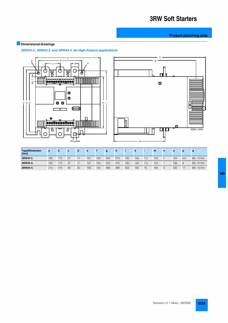
8122019 Arr Estado Solido
httpslidepdfcomreaderfullarr-estado-solido 3340
3RW Soft Starters
Project planning aids
Dimensional drawings
3RW44 2 3RW44 3 and 3RW44 4 for High-Feature applications
TypeDimension(mm)
a b c d e f g h I k l m n o p q
3RW44 2 180 170 37 11 167 100 240 270 180 148 75 153 7 184 66 M6 10 Nm
3RW44 3 180 170 37 17 167 100 240 270 180 148 75 153 7 198 9 M6 10 Nm
3RW44 4 210 210 48 25 190 140 269 298 205 166 16 166 9 230 11 M8 15 Nm
8122019 Arr Estado Solido
httpslidepdfcomreaderfullarr-estado-solido 3440
3RW Soft Starters
Project planning aids
3RW44 5 for High-Feature applications
147
173
195
118
N S B 0_
0 1 6 5 3
261
290
249
162
152
6 2 3
1 0 5
2 5 3
1 6 5
76
44
470
510
1
5 5
2
0Oslash14 40
6 3 8 5
5 9 0
8122019 Arr Estado Solido
httpslidepdfcomreaderfullarr-estado-solido 3540
3RW Soft Starters
Project planning aids
Schematics
1) Permissible values for main and control voltagesee Technical Specifications
3RW44 connection examples for main and control circuits
Main circuit Control circuitPossibility 1a Possibility 1Inline circuit with circuit-breaker and SITOR fuse(semiconductor protection only)
Control by pushbutton
Main circuit
Possibility 1b Possibility 1cInline circuit with full-rangeprotection (line andsemiconductor protection)
Inline circuit with line andSITOR fuse(semiconductor protection only)
Q1
L3L2L1
G1
F3
T1 T2 T3
M1
N S B 0_
0 1 4 9 0 a
L1 L2 L3
V1U1 W1
MPE 3~
3NPE 400 V AC 50 Hz
(optionalsemiconductorprotection fuse)
13 14 23 24 33 34 95 9896 +
T1 T2IN4IN3IN2IN1L-L+A1
A2
NPE
PE
G1
F2
NSB0_01494a
S t a r t
S 2
R e s e t S
3
StopS1
L1
On periodGrouperror
N o a c t i o n
N o a c t i o n
Noaction
PTC type Aor
Thermoclick
Noaction
1NPE 230 V AC 50 Hz
M o t o r o
n r i g h t
P S
1
1)
8122019 Arr Estado Solido
httpslidepdfcomreaderfullarr-estado-solido 3640
3RW Soft Starters
Project planning aids
1) Permissible values for main and control voltagesee Technical Specifications
2) Caution Risk of restartingThe start command (eg from the PLC) must be reset prior to a resetcommand because a new automatic restart will take place automaticallyif a start command is active after the reset command This appliesespecially in case of motor protection trippingFor safety reasons we recommend incorporating the group error output(terminals 95 and 96) in the controller
Main circuit Control circuit
Possibility 2 Possibility 2Inline circuit with main contactor Control of a main contactor and control by means of PLC
Q1
L3L2L1
G1
K1
F3
L1 L2 L3
T1 T2 T3
M1
N S B 0_
0 1 4 9 5 a
V1U1 W1
MPE 3~
1)
(optionalsemiconductorprotection)
(optional linecontactor if floatingswitching of themotor is planned)
3NPE 400 V AC 50 Hz
13 14 23 24 33 34 95 9896+
T1 T2IN4IN3IN2IN1L-L+A1
A2
NPE
PE
G1
K1NSB0_01496a
F2+24 V DC
M
L1 1NPE AC 230 V 50 Hz1)
Switch-on duration
M o t o r r i g h t
T r i p R e s e t
PLC outputs PLC inputs
N o a c t i o n
N o a c t i o n
No action No action
Group error
PTC type A Thermoclick
(optional line contactorif floating switchingof the motor is planned)
P S 1
ResetStart 2)
8122019 Arr Estado Solido
httpslidepdfcomreaderfullarr-estado-solido 3740
3RW Soft Starters
Project planning aids
1) Permissible values for main and control voltagesee Technical Specifications
2) Caution Risk of restartingThe start command (eg from the PLC) must be reset prior to a resetcommand because a new automatic restart will take place automaticallyif a start command is active after the reset command This applies espe-cially in case of motor protection trippingFor safety reasons we recommend incorporating the group error output(terminals 95 and 96) in the controller
3) If the ramp-down function Combined braking is selected no brakingcontactor is requiredIf the ramp-down function DC braking is selected a braking contactormust be used in addition Type see Fuse Coordination (inline circuit) onpages 621 to 623For applications with large centrifugal masses (J Load gt J Motor) werecommend the function DC brakingThe output 2 must be switched over to DC braking contactor
4) Auxiliary relay K4 egLZXRT4A4T30 (230 V AC rated control supply voltage)LZXRT4A4S15 (115 V AC rated control supply voltage)
Main circuit Control circuit
Possibility 3a Possibility 3aInline circuit with ramp-down function DC braking3)
(for device types 3RW44 22 to 3RW44 25)Control of the braking contactor3)
Main circuit Control circuit
Possibility 3b Possibility 3bInline circuit with ramp-down function DC braking3)
(for device types 3RW44 26 to 3RW44 47)Control of the braking contactor3)
Q1
L3L2
G1
F3
T1 T2 T3
M1
N S B 0_
0 1 5 0 1 a
L1 L2 L3
V1U1 W1
M
K2 K2 K2
PE 3~
1)
2
(optionalsemi-conductorprotection)
L1 3NPE 400 V AC 50 Hz
13 14 23 24 33 34 95 9896 +
T1 T2IN4IN3IN2IN1L-L+A1
A2
NPE
PEG1
K2NSB0_01502
R e s e t
M Start Reset
+24 V DC
K2
F2
1)
2)
No action Group error
N o a c t i o n
N o a c t i o n
On period
PLC output
PTC type Aor
Thermoclick
L1 1NPE 230 V AC 50 Hz
DC braking contactor 3)
K2 K33 3
G1
F3
T1 T2 T3
M1
N S B 0_
0 1
5 0 3 a
L1 L2 L3
V1U1 W1
MPE 3~
Q1
L3L2
1)
(optionalsemi-conductorprotection)
L1 3NPE 400 V AC 50 Hz
13 14 23 24 33 34 95 9896 +
T1 T2IN4IN3IN2IN1L-L+A1
A2
NPE
PE
G1
K4
NSB0_01504
R e s e t
K4 K4
K3 K2
K2 K3
+24 V DC
M Start Reset
F2
1)
2)
4)
PLC output
No action Group error
N o a c t i o n
N o a c t i o n
ON period
PTC type Aor
Thermoclick
M o t o r o n r i g h t
L1 1NPE 230 V AC 50 Hz
DC braking contactor 3)
8122019 Arr Estado Solido
httpslidepdfcomreaderfullarr-estado-solido 3840
3RW Soft Starters
Notes
1) Permissible values for main and control voltagesee Technical Specifications
2) Caution Risk of restartingThe start command (eg from the PLC) must be reset prior to a resetcommand because a new automatic restart will take place automaticallyif a start command is active after the reset command This appliesespecially in case of motor protection trippingFor safety reasons we recommend incorporating the group error output(terminals 95 and 96) in the controller
Main circuit Control circuit
Possibility 4a Possibility 4b Possibility 4Inside-delta circuit Change of direction of rotation for
inside-delta circuitControl by means of PLC
13 14 23 24 33 34 95 9896+
T1 T2IN4IN3IN2IN1L-L+A1
A2
NPE
PEG1
NSB0_01498a
+24 V DC
M
F2
L1 1NPE AC 230 V 50 Hz1)
2)
R e s e t
Switch-onduration
No action
Group error
N o a c t i o n
N o a c t i o n
No action
PTC type A orThermoclick
M o t o r r i g h t
PLC outputs PLC inputs
Start Reset
7
8122019 Arr Estado Solido
httpslidepdfcomreaderfullarr-estado-solido 3940
Appendix
Conditions of sale and delivery
Terms and Conditions of Sale and Delivery
By using this catalog you can acquire hardware and softwareproducts described therein from the Siemens AG subject to the
following terms Please note The scope the quality and the con-ditions for supplies and services including software productsby any Siemens entity having a registered office outside of Ger-many shall be subject exclusively to the General Terms andConditions of the respective Siemens entity
For customers with a seat or registered office in theFederal Republic of Germany
The bdquoGeneral Terms of Paymentldquo as well as the bdquoGeneral Condi-tions for the Supply of Products and Services of the Electricaland Electronics Industryldquo shall apply
For software products the bdquoGeneral License Conditions for Soft-ware Products for Automation and Drives for Customers with aSeat or registered Office in Germanyldquo shall apply
For customers with a seat or registered office outside of
Germany The bdquoGeneral Terms of Paymentldquo as well as the bdquoGeneral Condi-tions for Supplies of Siemens Automation and Drives for Cus-tomers with a Seat or registered Office outside of Germanyldquo shallapply
For software products the bdquoGeneral License Conditions for Soft-ware Products for Automation and Drives for Customers with aSeat or registered Office outside of Germanyldquo shall apply
General
The prices are in 991404 (Euro) ex works exclusive packaging
The sales tax (value added tax) is not included in the pricesIt shall be debited separately at the respective rate according tothe applicable legal regulations
In addition to the prices of products which include silver plump
aluminum andor copper surcharges may be calculated if therespective limits of the notes are exceeded The respective note(eg source German newspaper bdquoHandesblattldquo in categorybdquodeutsche Edelmetalleldquo and bdquoMetallverarbeiterldquo) for silver (bdquover-arbeitetes Silberldquo) plump (bdquoBlei in Kabelnldquo) aluminum (bdquoAlumin-ium in Kabelnldquo) and copper (bdquoElektrolytkupferldquo bdquoDEL-Notizldquo) re-spectively of the day the order or rather the on call order isreceived is decisive for the calculation of the surcharges
Surcharges of copper shall be calculated for Drives at a note(bdquoDEL-Notizldquo) above EUR 22500 100 Kg and for chokes trans-formers above EUR 15000 100 kg
Surcharges shall be charged based on the quantities of the ma-terials which are contained in the relevant products
Prices are subject to change without prior notice We will debitthe prices valid at the time of delivery
The dimensions are in mm In Germany according to the Ger-man law on units in measuring technology data in inches onlyapply to devices for export
Illustrations are not binding
Insofar as there are no remarks on the corresponding pages- especially with regard to data dimensions and weights given -these are subject to change without prior notice
Comprehensive Terms and Conditions of Sale and Delivery areavailable free of charge from your local Siemens business officeunder the following Order Nos
bull 6ZB5310-0KR30-0BA0(for customers based in the Federal Republic of Germany)
bull 6ZB5310-0KS53-0BA0(for customers based outside of theFederal Republic ofGermany)
or download them from the Internethttpwwwsiemenscomautomationmall (Germany AampD Mall Online-Help System)
Export regulations
The products listed in this catalog price list may be subject toEuropean German andor US export regulations
Therefore any export requiring a license is subject to approvalby the competent authorities
According to current provisions the following export regulations
must be observed with respect to the products featured in thiscatalog price list
Even without a label or with an ldquoAL Nldquo or ldquoECCN Nldquo authoriza-tion may be required due to the final destination and purpose forwhich the goods are to be used
The deciding factors are the AL or ECCN export authorizationindicated on order confirmations delivery notes and invoices
Errors excepted and subject to change without prior notice
AampDVuLEn 060306
AL Number of the German Export List
Products marked other than ldquoNldquo require an exportlicenseIn the case of software products the export des-ignations of the relevant data medium must alsobe generally adhered to
Goods labeled with an ldquoAL not equal to Nldquo aresubject to a European or German export authori-zation when being exported out of the EU
ECCN Export Control Classification Number
Products marked other than ldquoNldquo are subject to a
reexport license to specific countriesIn the case of software products the exportdesignations of the relevant data medium mustalso be generally adhered to
Goods labeled with an ldquoECCN not equal to Nldquo aresubject to a US re-export authorization
_ _ _ _
8122019 Arr Estado Solido
httpslidepdfcomreaderfullarr-estado-solido 4040
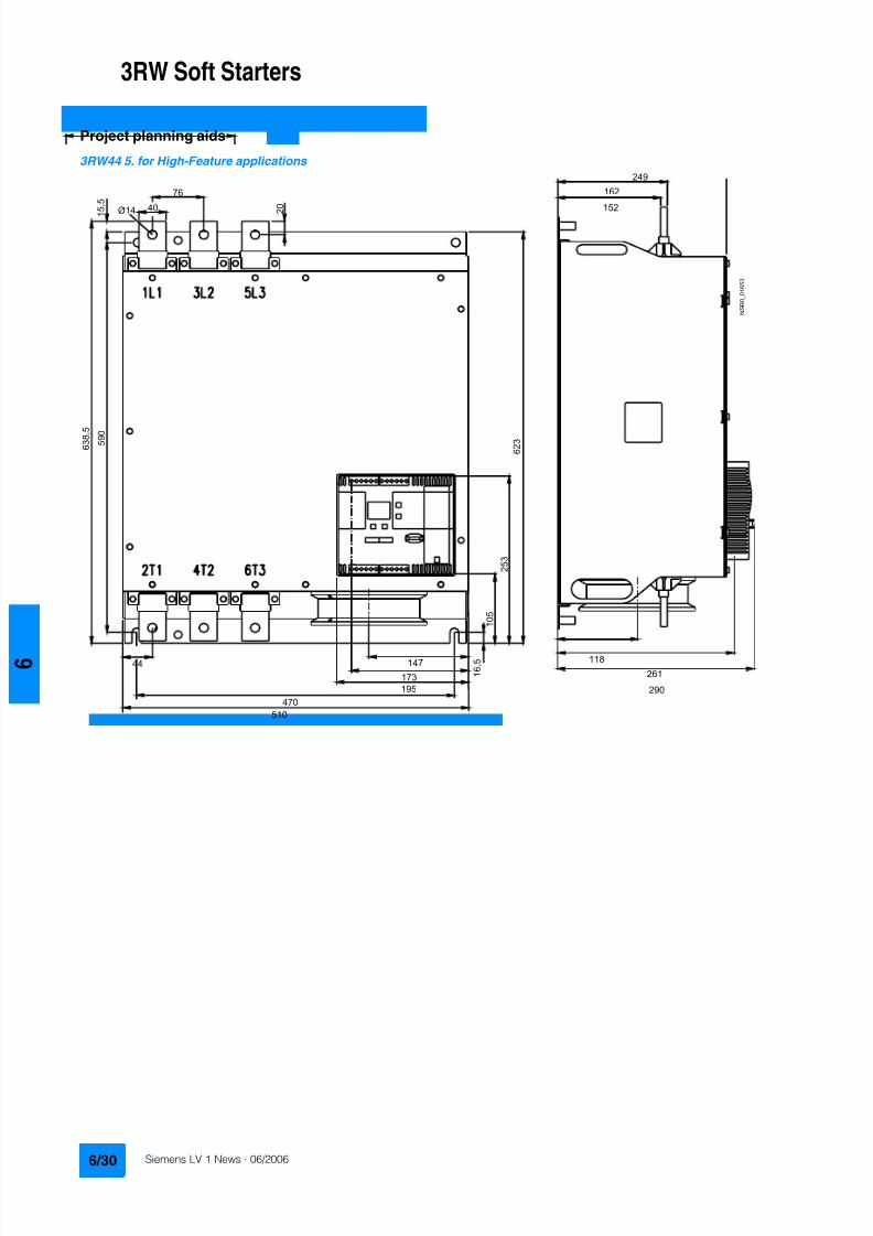
8122019 Arr Estado Solido
httpslidepdfcomreaderfullarr-estado-solido 3440
3RW Soft Starters
Project planning aids
3RW44 5 for High-Feature applications
147
173
195
118
N S B 0_
0 1 6 5 3
261
290
249
162
152
6 2 3
1 0 5
2 5 3
1 6 5
76
44
470
510
1
5 5
2
0Oslash14 40
6 3 8 5
5 9 0
8122019 Arr Estado Solido
httpslidepdfcomreaderfullarr-estado-solido 3540
3RW Soft Starters
Project planning aids
Schematics
1) Permissible values for main and control voltagesee Technical Specifications
3RW44 connection examples for main and control circuits
Main circuit Control circuitPossibility 1a Possibility 1Inline circuit with circuit-breaker and SITOR fuse(semiconductor protection only)
Control by pushbutton
Main circuit
Possibility 1b Possibility 1cInline circuit with full-rangeprotection (line andsemiconductor protection)
Inline circuit with line andSITOR fuse(semiconductor protection only)
Q1
L3L2L1
G1
F3
T1 T2 T3
M1
N S B 0_
0 1 4 9 0 a
L1 L2 L3
V1U1 W1
MPE 3~
3NPE 400 V AC 50 Hz
(optionalsemiconductorprotection fuse)
13 14 23 24 33 34 95 9896 +
T1 T2IN4IN3IN2IN1L-L+A1
A2
NPE
PE
G1
F2
NSB0_01494a
S t a r t
S 2
R e s e t S
3
StopS1
L1
On periodGrouperror
N o a c t i o n
N o a c t i o n
Noaction
PTC type Aor
Thermoclick
Noaction
1NPE 230 V AC 50 Hz
M o t o r o
n r i g h t
P S
1
1)
8122019 Arr Estado Solido
httpslidepdfcomreaderfullarr-estado-solido 3640
3RW Soft Starters
Project planning aids
1) Permissible values for main and control voltagesee Technical Specifications
2) Caution Risk of restartingThe start command (eg from the PLC) must be reset prior to a resetcommand because a new automatic restart will take place automaticallyif a start command is active after the reset command This appliesespecially in case of motor protection trippingFor safety reasons we recommend incorporating the group error output(terminals 95 and 96) in the controller
Main circuit Control circuit
Possibility 2 Possibility 2Inline circuit with main contactor Control of a main contactor and control by means of PLC
Q1
L3L2L1
G1
K1
F3
L1 L2 L3
T1 T2 T3
M1
N S B 0_
0 1 4 9 5 a
V1U1 W1
MPE 3~
1)
(optionalsemiconductorprotection)
(optional linecontactor if floatingswitching of themotor is planned)
3NPE 400 V AC 50 Hz
13 14 23 24 33 34 95 9896+
T1 T2IN4IN3IN2IN1L-L+A1
A2
NPE
PE
G1
K1NSB0_01496a
F2+24 V DC
M
L1 1NPE AC 230 V 50 Hz1)
Switch-on duration
M o t o r r i g h t
T r i p R e s e t
PLC outputs PLC inputs
N o a c t i o n
N o a c t i o n
No action No action
Group error
PTC type A Thermoclick
(optional line contactorif floating switchingof the motor is planned)
P S 1
ResetStart 2)
8122019 Arr Estado Solido
httpslidepdfcomreaderfullarr-estado-solido 3740
3RW Soft Starters
Project planning aids
1) Permissible values for main and control voltagesee Technical Specifications
2) Caution Risk of restartingThe start command (eg from the PLC) must be reset prior to a resetcommand because a new automatic restart will take place automaticallyif a start command is active after the reset command This applies espe-cially in case of motor protection trippingFor safety reasons we recommend incorporating the group error output(terminals 95 and 96) in the controller
3) If the ramp-down function Combined braking is selected no brakingcontactor is requiredIf the ramp-down function DC braking is selected a braking contactormust be used in addition Type see Fuse Coordination (inline circuit) onpages 621 to 623For applications with large centrifugal masses (J Load gt J Motor) werecommend the function DC brakingThe output 2 must be switched over to DC braking contactor
4) Auxiliary relay K4 egLZXRT4A4T30 (230 V AC rated control supply voltage)LZXRT4A4S15 (115 V AC rated control supply voltage)
Main circuit Control circuit
Possibility 3a Possibility 3aInline circuit with ramp-down function DC braking3)
(for device types 3RW44 22 to 3RW44 25)Control of the braking contactor3)
Main circuit Control circuit
Possibility 3b Possibility 3bInline circuit with ramp-down function DC braking3)
(for device types 3RW44 26 to 3RW44 47)Control of the braking contactor3)
Q1
L3L2
G1
F3
T1 T2 T3
M1
N S B 0_
0 1 5 0 1 a
L1 L2 L3
V1U1 W1
M
K2 K2 K2
PE 3~
1)
2
(optionalsemi-conductorprotection)
L1 3NPE 400 V AC 50 Hz
13 14 23 24 33 34 95 9896 +
T1 T2IN4IN3IN2IN1L-L+A1
A2
NPE
PEG1
K2NSB0_01502
R e s e t
M Start Reset
+24 V DC
K2
F2
1)
2)
No action Group error
N o a c t i o n
N o a c t i o n
On period
PLC output
PTC type Aor
Thermoclick
L1 1NPE 230 V AC 50 Hz
DC braking contactor 3)
K2 K33 3
G1
F3
T1 T2 T3
M1
N S B 0_
0 1
5 0 3 a
L1 L2 L3
V1U1 W1
MPE 3~
Q1
L3L2
1)
(optionalsemi-conductorprotection)
L1 3NPE 400 V AC 50 Hz
13 14 23 24 33 34 95 9896 +
T1 T2IN4IN3IN2IN1L-L+A1
A2
NPE
PE
G1
K4
NSB0_01504
R e s e t
K4 K4
K3 K2
K2 K3
+24 V DC
M Start Reset
F2
1)
2)
4)
PLC output
No action Group error
N o a c t i o n
N o a c t i o n
ON period
PTC type Aor
Thermoclick
M o t o r o n r i g h t
L1 1NPE 230 V AC 50 Hz
DC braking contactor 3)
8122019 Arr Estado Solido
httpslidepdfcomreaderfullarr-estado-solido 3840
3RW Soft Starters
Notes
1) Permissible values for main and control voltagesee Technical Specifications
2) Caution Risk of restartingThe start command (eg from the PLC) must be reset prior to a resetcommand because a new automatic restart will take place automaticallyif a start command is active after the reset command This appliesespecially in case of motor protection trippingFor safety reasons we recommend incorporating the group error output(terminals 95 and 96) in the controller
Main circuit Control circuit
Possibility 4a Possibility 4b Possibility 4Inside-delta circuit Change of direction of rotation for
inside-delta circuitControl by means of PLC
13 14 23 24 33 34 95 9896+
T1 T2IN4IN3IN2IN1L-L+A1
A2
NPE
PEG1
NSB0_01498a
+24 V DC
M
F2
L1 1NPE AC 230 V 50 Hz1)
2)
R e s e t
Switch-onduration
No action
Group error
N o a c t i o n
N o a c t i o n
No action
PTC type A orThermoclick
M o t o r r i g h t
PLC outputs PLC inputs
Start Reset
7
8122019 Arr Estado Solido
httpslidepdfcomreaderfullarr-estado-solido 3940
Appendix
Conditions of sale and delivery
Terms and Conditions of Sale and Delivery
By using this catalog you can acquire hardware and softwareproducts described therein from the Siemens AG subject to the
following terms Please note The scope the quality and the con-ditions for supplies and services including software productsby any Siemens entity having a registered office outside of Ger-many shall be subject exclusively to the General Terms andConditions of the respective Siemens entity
For customers with a seat or registered office in theFederal Republic of Germany
The bdquoGeneral Terms of Paymentldquo as well as the bdquoGeneral Condi-tions for the Supply of Products and Services of the Electricaland Electronics Industryldquo shall apply
For software products the bdquoGeneral License Conditions for Soft-ware Products for Automation and Drives for Customers with aSeat or registered Office in Germanyldquo shall apply
For customers with a seat or registered office outside of
Germany The bdquoGeneral Terms of Paymentldquo as well as the bdquoGeneral Condi-tions for Supplies of Siemens Automation and Drives for Cus-tomers with a Seat or registered Office outside of Germanyldquo shallapply
For software products the bdquoGeneral License Conditions for Soft-ware Products for Automation and Drives for Customers with aSeat or registered Office outside of Germanyldquo shall apply
General
The prices are in 991404 (Euro) ex works exclusive packaging
The sales tax (value added tax) is not included in the pricesIt shall be debited separately at the respective rate according tothe applicable legal regulations
In addition to the prices of products which include silver plump
aluminum andor copper surcharges may be calculated if therespective limits of the notes are exceeded The respective note(eg source German newspaper bdquoHandesblattldquo in categorybdquodeutsche Edelmetalleldquo and bdquoMetallverarbeiterldquo) for silver (bdquover-arbeitetes Silberldquo) plump (bdquoBlei in Kabelnldquo) aluminum (bdquoAlumin-ium in Kabelnldquo) and copper (bdquoElektrolytkupferldquo bdquoDEL-Notizldquo) re-spectively of the day the order or rather the on call order isreceived is decisive for the calculation of the surcharges
Surcharges of copper shall be calculated for Drives at a note(bdquoDEL-Notizldquo) above EUR 22500 100 Kg and for chokes trans-formers above EUR 15000 100 kg
Surcharges shall be charged based on the quantities of the ma-terials which are contained in the relevant products
Prices are subject to change without prior notice We will debitthe prices valid at the time of delivery
The dimensions are in mm In Germany according to the Ger-man law on units in measuring technology data in inches onlyapply to devices for export
Illustrations are not binding
Insofar as there are no remarks on the corresponding pages- especially with regard to data dimensions and weights given -these are subject to change without prior notice
Comprehensive Terms and Conditions of Sale and Delivery areavailable free of charge from your local Siemens business officeunder the following Order Nos
bull 6ZB5310-0KR30-0BA0(for customers based in the Federal Republic of Germany)
bull 6ZB5310-0KS53-0BA0(for customers based outside of theFederal Republic ofGermany)
or download them from the Internethttpwwwsiemenscomautomationmall (Germany AampD Mall Online-Help System)
Export regulations
The products listed in this catalog price list may be subject toEuropean German andor US export regulations
Therefore any export requiring a license is subject to approvalby the competent authorities
According to current provisions the following export regulations
must be observed with respect to the products featured in thiscatalog price list
Even without a label or with an ldquoAL Nldquo or ldquoECCN Nldquo authoriza-tion may be required due to the final destination and purpose forwhich the goods are to be used
The deciding factors are the AL or ECCN export authorizationindicated on order confirmations delivery notes and invoices
Errors excepted and subject to change without prior notice
AampDVuLEn 060306
AL Number of the German Export List
Products marked other than ldquoNldquo require an exportlicenseIn the case of software products the export des-ignations of the relevant data medium must alsobe generally adhered to
Goods labeled with an ldquoAL not equal to Nldquo aresubject to a European or German export authori-zation when being exported out of the EU
ECCN Export Control Classification Number
Products marked other than ldquoNldquo are subject to a
reexport license to specific countriesIn the case of software products the exportdesignations of the relevant data medium mustalso be generally adhered to
Goods labeled with an ldquoECCN not equal to Nldquo aresubject to a US re-export authorization
_ _ _ _
8122019 Arr Estado Solido
httpslidepdfcomreaderfullarr-estado-solido 4040
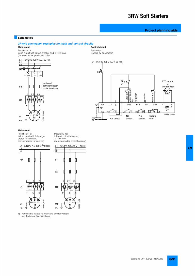
8122019 Arr Estado Solido
httpslidepdfcomreaderfullarr-estado-solido 3540
3RW Soft Starters
Project planning aids
Schematics
1) Permissible values for main and control voltagesee Technical Specifications
3RW44 connection examples for main and control circuits
Main circuit Control circuitPossibility 1a Possibility 1Inline circuit with circuit-breaker and SITOR fuse(semiconductor protection only)
Control by pushbutton
Main circuit
Possibility 1b Possibility 1cInline circuit with full-rangeprotection (line andsemiconductor protection)
Inline circuit with line andSITOR fuse(semiconductor protection only)
Q1
L3L2L1
G1
F3
T1 T2 T3
M1
N S B 0_
0 1 4 9 0 a
L1 L2 L3
V1U1 W1
MPE 3~
3NPE 400 V AC 50 Hz
(optionalsemiconductorprotection fuse)
13 14 23 24 33 34 95 9896 +
T1 T2IN4IN3IN2IN1L-L+A1
A2
NPE
PE
G1
F2
NSB0_01494a
S t a r t
S 2
R e s e t S
3
StopS1
L1
On periodGrouperror
N o a c t i o n
N o a c t i o n
Noaction
PTC type Aor
Thermoclick
Noaction
1NPE 230 V AC 50 Hz
M o t o r o
n r i g h t
P S
1
1)
8122019 Arr Estado Solido
httpslidepdfcomreaderfullarr-estado-solido 3640
3RW Soft Starters
Project planning aids
1) Permissible values for main and control voltagesee Technical Specifications
2) Caution Risk of restartingThe start command (eg from the PLC) must be reset prior to a resetcommand because a new automatic restart will take place automaticallyif a start command is active after the reset command This appliesespecially in case of motor protection trippingFor safety reasons we recommend incorporating the group error output(terminals 95 and 96) in the controller
Main circuit Control circuit
Possibility 2 Possibility 2Inline circuit with main contactor Control of a main contactor and control by means of PLC
Q1
L3L2L1
G1
K1
F3
L1 L2 L3
T1 T2 T3
M1
N S B 0_
0 1 4 9 5 a
V1U1 W1
MPE 3~
1)
(optionalsemiconductorprotection)
(optional linecontactor if floatingswitching of themotor is planned)
3NPE 400 V AC 50 Hz
13 14 23 24 33 34 95 9896+
T1 T2IN4IN3IN2IN1L-L+A1
A2
NPE
PE
G1
K1NSB0_01496a
F2+24 V DC
M
L1 1NPE AC 230 V 50 Hz1)
Switch-on duration
M o t o r r i g h t
T r i p R e s e t
PLC outputs PLC inputs
N o a c t i o n
N o a c t i o n
No action No action
Group error
PTC type A Thermoclick
(optional line contactorif floating switchingof the motor is planned)
P S 1
ResetStart 2)
8122019 Arr Estado Solido
httpslidepdfcomreaderfullarr-estado-solido 3740
3RW Soft Starters
Project planning aids
1) Permissible values for main and control voltagesee Technical Specifications
2) Caution Risk of restartingThe start command (eg from the PLC) must be reset prior to a resetcommand because a new automatic restart will take place automaticallyif a start command is active after the reset command This applies espe-cially in case of motor protection trippingFor safety reasons we recommend incorporating the group error output(terminals 95 and 96) in the controller
3) If the ramp-down function Combined braking is selected no brakingcontactor is requiredIf the ramp-down function DC braking is selected a braking contactormust be used in addition Type see Fuse Coordination (inline circuit) onpages 621 to 623For applications with large centrifugal masses (J Load gt J Motor) werecommend the function DC brakingThe output 2 must be switched over to DC braking contactor
4) Auxiliary relay K4 egLZXRT4A4T30 (230 V AC rated control supply voltage)LZXRT4A4S15 (115 V AC rated control supply voltage)
Main circuit Control circuit
Possibility 3a Possibility 3aInline circuit with ramp-down function DC braking3)
(for device types 3RW44 22 to 3RW44 25)Control of the braking contactor3)
Main circuit Control circuit
Possibility 3b Possibility 3bInline circuit with ramp-down function DC braking3)
(for device types 3RW44 26 to 3RW44 47)Control of the braking contactor3)
Q1
L3L2
G1
F3
T1 T2 T3
M1
N S B 0_
0 1 5 0 1 a
L1 L2 L3
V1U1 W1
M
K2 K2 K2
PE 3~
1)
2
(optionalsemi-conductorprotection)
L1 3NPE 400 V AC 50 Hz
13 14 23 24 33 34 95 9896 +
T1 T2IN4IN3IN2IN1L-L+A1
A2
NPE
PEG1
K2NSB0_01502
R e s e t
M Start Reset
+24 V DC
K2
F2
1)
2)
No action Group error
N o a c t i o n
N o a c t i o n
On period
PLC output
PTC type Aor
Thermoclick
L1 1NPE 230 V AC 50 Hz
DC braking contactor 3)
K2 K33 3
G1
F3
T1 T2 T3
M1
N S B 0_
0 1
5 0 3 a
L1 L2 L3
V1U1 W1
MPE 3~
Q1
L3L2
1)
(optionalsemi-conductorprotection)
L1 3NPE 400 V AC 50 Hz
13 14 23 24 33 34 95 9896 +
T1 T2IN4IN3IN2IN1L-L+A1
A2
NPE
PE
G1
K4
NSB0_01504
R e s e t
K4 K4
K3 K2
K2 K3
+24 V DC
M Start Reset
F2
1)
2)
4)
PLC output
No action Group error
N o a c t i o n
N o a c t i o n
ON period
PTC type Aor
Thermoclick
M o t o r o n r i g h t
L1 1NPE 230 V AC 50 Hz
DC braking contactor 3)
8122019 Arr Estado Solido
httpslidepdfcomreaderfullarr-estado-solido 3840
3RW Soft Starters
Notes
1) Permissible values for main and control voltagesee Technical Specifications
2) Caution Risk of restartingThe start command (eg from the PLC) must be reset prior to a resetcommand because a new automatic restart will take place automaticallyif a start command is active after the reset command This appliesespecially in case of motor protection trippingFor safety reasons we recommend incorporating the group error output(terminals 95 and 96) in the controller
Main circuit Control circuit
Possibility 4a Possibility 4b Possibility 4Inside-delta circuit Change of direction of rotation for
inside-delta circuitControl by means of PLC
13 14 23 24 33 34 95 9896+
T1 T2IN4IN3IN2IN1L-L+A1
A2
NPE
PEG1
NSB0_01498a
+24 V DC
M
F2
L1 1NPE AC 230 V 50 Hz1)
2)
R e s e t
Switch-onduration
No action
Group error
N o a c t i o n
N o a c t i o n
No action
PTC type A orThermoclick
M o t o r r i g h t
PLC outputs PLC inputs
Start Reset
7
8122019 Arr Estado Solido
httpslidepdfcomreaderfullarr-estado-solido 3940
Appendix
Conditions of sale and delivery
Terms and Conditions of Sale and Delivery
By using this catalog you can acquire hardware and softwareproducts described therein from the Siemens AG subject to the
following terms Please note The scope the quality and the con-ditions for supplies and services including software productsby any Siemens entity having a registered office outside of Ger-many shall be subject exclusively to the General Terms andConditions of the respective Siemens entity
For customers with a seat or registered office in theFederal Republic of Germany
The bdquoGeneral Terms of Paymentldquo as well as the bdquoGeneral Condi-tions for the Supply of Products and Services of the Electricaland Electronics Industryldquo shall apply
For software products the bdquoGeneral License Conditions for Soft-ware Products for Automation and Drives for Customers with aSeat or registered Office in Germanyldquo shall apply
For customers with a seat or registered office outside of
Germany The bdquoGeneral Terms of Paymentldquo as well as the bdquoGeneral Condi-tions for Supplies of Siemens Automation and Drives for Cus-tomers with a Seat or registered Office outside of Germanyldquo shallapply
For software products the bdquoGeneral License Conditions for Soft-ware Products for Automation and Drives for Customers with aSeat or registered Office outside of Germanyldquo shall apply
General
The prices are in 991404 (Euro) ex works exclusive packaging
The sales tax (value added tax) is not included in the pricesIt shall be debited separately at the respective rate according tothe applicable legal regulations
In addition to the prices of products which include silver plump
aluminum andor copper surcharges may be calculated if therespective limits of the notes are exceeded The respective note(eg source German newspaper bdquoHandesblattldquo in categorybdquodeutsche Edelmetalleldquo and bdquoMetallverarbeiterldquo) for silver (bdquover-arbeitetes Silberldquo) plump (bdquoBlei in Kabelnldquo) aluminum (bdquoAlumin-ium in Kabelnldquo) and copper (bdquoElektrolytkupferldquo bdquoDEL-Notizldquo) re-spectively of the day the order or rather the on call order isreceived is decisive for the calculation of the surcharges
Surcharges of copper shall be calculated for Drives at a note(bdquoDEL-Notizldquo) above EUR 22500 100 Kg and for chokes trans-formers above EUR 15000 100 kg
Surcharges shall be charged based on the quantities of the ma-terials which are contained in the relevant products
Prices are subject to change without prior notice We will debitthe prices valid at the time of delivery
The dimensions are in mm In Germany according to the Ger-man law on units in measuring technology data in inches onlyapply to devices for export
Illustrations are not binding
Insofar as there are no remarks on the corresponding pages- especially with regard to data dimensions and weights given -these are subject to change without prior notice
Comprehensive Terms and Conditions of Sale and Delivery areavailable free of charge from your local Siemens business officeunder the following Order Nos
bull 6ZB5310-0KR30-0BA0(for customers based in the Federal Republic of Germany)
bull 6ZB5310-0KS53-0BA0(for customers based outside of theFederal Republic ofGermany)
or download them from the Internethttpwwwsiemenscomautomationmall (Germany AampD Mall Online-Help System)
Export regulations
The products listed in this catalog price list may be subject toEuropean German andor US export regulations
Therefore any export requiring a license is subject to approvalby the competent authorities
According to current provisions the following export regulations
must be observed with respect to the products featured in thiscatalog price list
Even without a label or with an ldquoAL Nldquo or ldquoECCN Nldquo authoriza-tion may be required due to the final destination and purpose forwhich the goods are to be used
The deciding factors are the AL or ECCN export authorizationindicated on order confirmations delivery notes and invoices
Errors excepted and subject to change without prior notice
AampDVuLEn 060306
AL Number of the German Export List
Products marked other than ldquoNldquo require an exportlicenseIn the case of software products the export des-ignations of the relevant data medium must alsobe generally adhered to
Goods labeled with an ldquoAL not equal to Nldquo aresubject to a European or German export authori-zation when being exported out of the EU
ECCN Export Control Classification Number
Products marked other than ldquoNldquo are subject to a
reexport license to specific countriesIn the case of software products the exportdesignations of the relevant data medium mustalso be generally adhered to
Goods labeled with an ldquoECCN not equal to Nldquo aresubject to a US re-export authorization
_ _ _ _
8122019 Arr Estado Solido
httpslidepdfcomreaderfullarr-estado-solido 4040
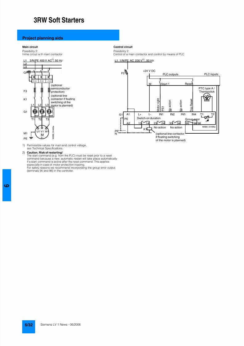
8122019 Arr Estado Solido
httpslidepdfcomreaderfullarr-estado-solido 3640
3RW Soft Starters
Project planning aids
1) Permissible values for main and control voltagesee Technical Specifications
2) Caution Risk of restartingThe start command (eg from the PLC) must be reset prior to a resetcommand because a new automatic restart will take place automaticallyif a start command is active after the reset command This appliesespecially in case of motor protection trippingFor safety reasons we recommend incorporating the group error output(terminals 95 and 96) in the controller
Main circuit Control circuit
Possibility 2 Possibility 2Inline circuit with main contactor Control of a main contactor and control by means of PLC
Q1
L3L2L1
G1
K1
F3
L1 L2 L3
T1 T2 T3
M1
N S B 0_
0 1 4 9 5 a
V1U1 W1
MPE 3~
1)
(optionalsemiconductorprotection)
(optional linecontactor if floatingswitching of themotor is planned)
3NPE 400 V AC 50 Hz
13 14 23 24 33 34 95 9896+
T1 T2IN4IN3IN2IN1L-L+A1
A2
NPE
PE
G1
K1NSB0_01496a
F2+24 V DC
M
L1 1NPE AC 230 V 50 Hz1)
Switch-on duration
M o t o r r i g h t
T r i p R e s e t
PLC outputs PLC inputs
N o a c t i o n
N o a c t i o n
No action No action
Group error
PTC type A Thermoclick
(optional line contactorif floating switchingof the motor is planned)
P S 1
ResetStart 2)
8122019 Arr Estado Solido
httpslidepdfcomreaderfullarr-estado-solido 3740
3RW Soft Starters
Project planning aids
1) Permissible values for main and control voltagesee Technical Specifications
2) Caution Risk of restartingThe start command (eg from the PLC) must be reset prior to a resetcommand because a new automatic restart will take place automaticallyif a start command is active after the reset command This applies espe-cially in case of motor protection trippingFor safety reasons we recommend incorporating the group error output(terminals 95 and 96) in the controller
3) If the ramp-down function Combined braking is selected no brakingcontactor is requiredIf the ramp-down function DC braking is selected a braking contactormust be used in addition Type see Fuse Coordination (inline circuit) onpages 621 to 623For applications with large centrifugal masses (J Load gt J Motor) werecommend the function DC brakingThe output 2 must be switched over to DC braking contactor
4) Auxiliary relay K4 egLZXRT4A4T30 (230 V AC rated control supply voltage)LZXRT4A4S15 (115 V AC rated control supply voltage)
Main circuit Control circuit
Possibility 3a Possibility 3aInline circuit with ramp-down function DC braking3)
(for device types 3RW44 22 to 3RW44 25)Control of the braking contactor3)
Main circuit Control circuit
Possibility 3b Possibility 3bInline circuit with ramp-down function DC braking3)
(for device types 3RW44 26 to 3RW44 47)Control of the braking contactor3)
Q1
L3L2
G1
F3
T1 T2 T3
M1
N S B 0_
0 1 5 0 1 a
L1 L2 L3
V1U1 W1
M
K2 K2 K2
PE 3~
1)
2
(optionalsemi-conductorprotection)
L1 3NPE 400 V AC 50 Hz
13 14 23 24 33 34 95 9896 +
T1 T2IN4IN3IN2IN1L-L+A1
A2
NPE
PEG1
K2NSB0_01502
R e s e t
M Start Reset
+24 V DC
K2
F2
1)
2)
No action Group error
N o a c t i o n
N o a c t i o n
On period
PLC output
PTC type Aor
Thermoclick
L1 1NPE 230 V AC 50 Hz
DC braking contactor 3)
K2 K33 3
G1
F3
T1 T2 T3
M1
N S B 0_
0 1
5 0 3 a
L1 L2 L3
V1U1 W1
MPE 3~
Q1
L3L2
1)
(optionalsemi-conductorprotection)
L1 3NPE 400 V AC 50 Hz
13 14 23 24 33 34 95 9896 +
T1 T2IN4IN3IN2IN1L-L+A1
A2
NPE
PE
G1
K4
NSB0_01504
R e s e t
K4 K4
K3 K2
K2 K3
+24 V DC
M Start Reset
F2
1)
2)
4)
PLC output
No action Group error
N o a c t i o n
N o a c t i o n
ON period
PTC type Aor
Thermoclick
M o t o r o n r i g h t
L1 1NPE 230 V AC 50 Hz
DC braking contactor 3)
8122019 Arr Estado Solido
httpslidepdfcomreaderfullarr-estado-solido 3840
3RW Soft Starters
Notes
1) Permissible values for main and control voltagesee Technical Specifications
2) Caution Risk of restartingThe start command (eg from the PLC) must be reset prior to a resetcommand because a new automatic restart will take place automaticallyif a start command is active after the reset command This appliesespecially in case of motor protection trippingFor safety reasons we recommend incorporating the group error output(terminals 95 and 96) in the controller
Main circuit Control circuit
Possibility 4a Possibility 4b Possibility 4Inside-delta circuit Change of direction of rotation for
inside-delta circuitControl by means of PLC
13 14 23 24 33 34 95 9896+
T1 T2IN4IN3IN2IN1L-L+A1
A2
NPE
PEG1
NSB0_01498a
+24 V DC
M
F2
L1 1NPE AC 230 V 50 Hz1)
2)
R e s e t
Switch-onduration
No action
Group error
N o a c t i o n
N o a c t i o n
No action
PTC type A orThermoclick
M o t o r r i g h t
PLC outputs PLC inputs
Start Reset
7
8122019 Arr Estado Solido
httpslidepdfcomreaderfullarr-estado-solido 3940
Appendix
Conditions of sale and delivery
Terms and Conditions of Sale and Delivery
By using this catalog you can acquire hardware and softwareproducts described therein from the Siemens AG subject to the
following terms Please note The scope the quality and the con-ditions for supplies and services including software productsby any Siemens entity having a registered office outside of Ger-many shall be subject exclusively to the General Terms andConditions of the respective Siemens entity
For customers with a seat or registered office in theFederal Republic of Germany
The bdquoGeneral Terms of Paymentldquo as well as the bdquoGeneral Condi-tions for the Supply of Products and Services of the Electricaland Electronics Industryldquo shall apply
For software products the bdquoGeneral License Conditions for Soft-ware Products for Automation and Drives for Customers with aSeat or registered Office in Germanyldquo shall apply
For customers with a seat or registered office outside of
Germany The bdquoGeneral Terms of Paymentldquo as well as the bdquoGeneral Condi-tions for Supplies of Siemens Automation and Drives for Cus-tomers with a Seat or registered Office outside of Germanyldquo shallapply
For software products the bdquoGeneral License Conditions for Soft-ware Products for Automation and Drives for Customers with aSeat or registered Office outside of Germanyldquo shall apply
General
The prices are in 991404 (Euro) ex works exclusive packaging
The sales tax (value added tax) is not included in the pricesIt shall be debited separately at the respective rate according tothe applicable legal regulations
In addition to the prices of products which include silver plump
aluminum andor copper surcharges may be calculated if therespective limits of the notes are exceeded The respective note(eg source German newspaper bdquoHandesblattldquo in categorybdquodeutsche Edelmetalleldquo and bdquoMetallverarbeiterldquo) for silver (bdquover-arbeitetes Silberldquo) plump (bdquoBlei in Kabelnldquo) aluminum (bdquoAlumin-ium in Kabelnldquo) and copper (bdquoElektrolytkupferldquo bdquoDEL-Notizldquo) re-spectively of the day the order or rather the on call order isreceived is decisive for the calculation of the surcharges
Surcharges of copper shall be calculated for Drives at a note(bdquoDEL-Notizldquo) above EUR 22500 100 Kg and for chokes trans-formers above EUR 15000 100 kg
Surcharges shall be charged based on the quantities of the ma-terials which are contained in the relevant products
Prices are subject to change without prior notice We will debitthe prices valid at the time of delivery
The dimensions are in mm In Germany according to the Ger-man law on units in measuring technology data in inches onlyapply to devices for export
Illustrations are not binding
Insofar as there are no remarks on the corresponding pages- especially with regard to data dimensions and weights given -these are subject to change without prior notice
Comprehensive Terms and Conditions of Sale and Delivery areavailable free of charge from your local Siemens business officeunder the following Order Nos
bull 6ZB5310-0KR30-0BA0(for customers based in the Federal Republic of Germany)
bull 6ZB5310-0KS53-0BA0(for customers based outside of theFederal Republic ofGermany)
or download them from the Internethttpwwwsiemenscomautomationmall (Germany AampD Mall Online-Help System)
Export regulations
The products listed in this catalog price list may be subject toEuropean German andor US export regulations
Therefore any export requiring a license is subject to approvalby the competent authorities
According to current provisions the following export regulations
must be observed with respect to the products featured in thiscatalog price list
Even without a label or with an ldquoAL Nldquo or ldquoECCN Nldquo authoriza-tion may be required due to the final destination and purpose forwhich the goods are to be used
The deciding factors are the AL or ECCN export authorizationindicated on order confirmations delivery notes and invoices
Errors excepted and subject to change without prior notice
AampDVuLEn 060306
AL Number of the German Export List
Products marked other than ldquoNldquo require an exportlicenseIn the case of software products the export des-ignations of the relevant data medium must alsobe generally adhered to
Goods labeled with an ldquoAL not equal to Nldquo aresubject to a European or German export authori-zation when being exported out of the EU
ECCN Export Control Classification Number
Products marked other than ldquoNldquo are subject to a
reexport license to specific countriesIn the case of software products the exportdesignations of the relevant data medium mustalso be generally adhered to
Goods labeled with an ldquoECCN not equal to Nldquo aresubject to a US re-export authorization
_ _ _ _
8122019 Arr Estado Solido
httpslidepdfcomreaderfullarr-estado-solido 4040
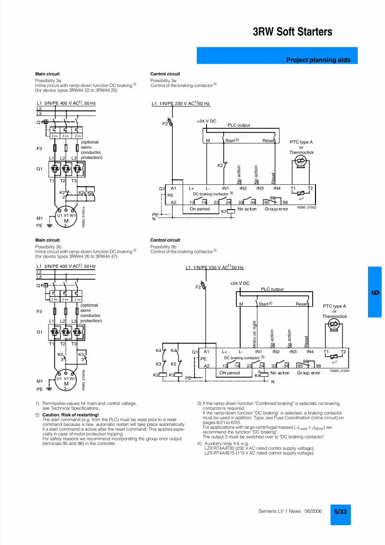
8122019 Arr Estado Solido
httpslidepdfcomreaderfullarr-estado-solido 3740
3RW Soft Starters
Project planning aids
1) Permissible values for main and control voltagesee Technical Specifications
2) Caution Risk of restartingThe start command (eg from the PLC) must be reset prior to a resetcommand because a new automatic restart will take place automaticallyif a start command is active after the reset command This applies espe-cially in case of motor protection trippingFor safety reasons we recommend incorporating the group error output(terminals 95 and 96) in the controller
3) If the ramp-down function Combined braking is selected no brakingcontactor is requiredIf the ramp-down function DC braking is selected a braking contactormust be used in addition Type see Fuse Coordination (inline circuit) onpages 621 to 623For applications with large centrifugal masses (J Load gt J Motor) werecommend the function DC brakingThe output 2 must be switched over to DC braking contactor
4) Auxiliary relay K4 egLZXRT4A4T30 (230 V AC rated control supply voltage)LZXRT4A4S15 (115 V AC rated control supply voltage)
Main circuit Control circuit
Possibility 3a Possibility 3aInline circuit with ramp-down function DC braking3)
(for device types 3RW44 22 to 3RW44 25)Control of the braking contactor3)
Main circuit Control circuit
Possibility 3b Possibility 3bInline circuit with ramp-down function DC braking3)
(for device types 3RW44 26 to 3RW44 47)Control of the braking contactor3)
Q1
L3L2
G1
F3
T1 T2 T3
M1
N S B 0_
0 1 5 0 1 a
L1 L2 L3
V1U1 W1
M
K2 K2 K2
PE 3~
1)
2
(optionalsemi-conductorprotection)
L1 3NPE 400 V AC 50 Hz
13 14 23 24 33 34 95 9896 +
T1 T2IN4IN3IN2IN1L-L+A1
A2
NPE
PEG1
K2NSB0_01502
R e s e t
M Start Reset
+24 V DC
K2
F2
1)
2)
No action Group error
N o a c t i o n
N o a c t i o n
On period
PLC output
PTC type Aor
Thermoclick
L1 1NPE 230 V AC 50 Hz
DC braking contactor 3)
K2 K33 3
G1
F3
T1 T2 T3
M1
N S B 0_
0 1
5 0 3 a
L1 L2 L3
V1U1 W1
MPE 3~
Q1
L3L2
1)
(optionalsemi-conductorprotection)
L1 3NPE 400 V AC 50 Hz
13 14 23 24 33 34 95 9896 +
T1 T2IN4IN3IN2IN1L-L+A1
A2
NPE
PE
G1
K4
NSB0_01504
R e s e t
K4 K4
K3 K2
K2 K3
+24 V DC
M Start Reset
F2
1)
2)
4)
PLC output
No action Group error
N o a c t i o n
N o a c t i o n
ON period
PTC type Aor
Thermoclick
M o t o r o n r i g h t
L1 1NPE 230 V AC 50 Hz
DC braking contactor 3)
8122019 Arr Estado Solido
httpslidepdfcomreaderfullarr-estado-solido 3840
3RW Soft Starters
Notes
1) Permissible values for main and control voltagesee Technical Specifications
2) Caution Risk of restartingThe start command (eg from the PLC) must be reset prior to a resetcommand because a new automatic restart will take place automaticallyif a start command is active after the reset command This appliesespecially in case of motor protection trippingFor safety reasons we recommend incorporating the group error output(terminals 95 and 96) in the controller
Main circuit Control circuit
Possibility 4a Possibility 4b Possibility 4Inside-delta circuit Change of direction of rotation for
inside-delta circuitControl by means of PLC
13 14 23 24 33 34 95 9896+
T1 T2IN4IN3IN2IN1L-L+A1
A2
NPE
PEG1
NSB0_01498a
+24 V DC
M
F2
L1 1NPE AC 230 V 50 Hz1)
2)
R e s e t
Switch-onduration
No action
Group error
N o a c t i o n
N o a c t i o n
No action
PTC type A orThermoclick
M o t o r r i g h t
PLC outputs PLC inputs
Start Reset
7
8122019 Arr Estado Solido
httpslidepdfcomreaderfullarr-estado-solido 3940
Appendix
Conditions of sale and delivery
Terms and Conditions of Sale and Delivery
By using this catalog you can acquire hardware and softwareproducts described therein from the Siemens AG subject to the
following terms Please note The scope the quality and the con-ditions for supplies and services including software productsby any Siemens entity having a registered office outside of Ger-many shall be subject exclusively to the General Terms andConditions of the respective Siemens entity
For customers with a seat or registered office in theFederal Republic of Germany
The bdquoGeneral Terms of Paymentldquo as well as the bdquoGeneral Condi-tions for the Supply of Products and Services of the Electricaland Electronics Industryldquo shall apply
For software products the bdquoGeneral License Conditions for Soft-ware Products for Automation and Drives for Customers with aSeat or registered Office in Germanyldquo shall apply
For customers with a seat or registered office outside of
Germany The bdquoGeneral Terms of Paymentldquo as well as the bdquoGeneral Condi-tions for Supplies of Siemens Automation and Drives for Cus-tomers with a Seat or registered Office outside of Germanyldquo shallapply
For software products the bdquoGeneral License Conditions for Soft-ware Products for Automation and Drives for Customers with aSeat or registered Office outside of Germanyldquo shall apply
General
The prices are in 991404 (Euro) ex works exclusive packaging
The sales tax (value added tax) is not included in the pricesIt shall be debited separately at the respective rate according tothe applicable legal regulations
In addition to the prices of products which include silver plump
aluminum andor copper surcharges may be calculated if therespective limits of the notes are exceeded The respective note(eg source German newspaper bdquoHandesblattldquo in categorybdquodeutsche Edelmetalleldquo and bdquoMetallverarbeiterldquo) for silver (bdquover-arbeitetes Silberldquo) plump (bdquoBlei in Kabelnldquo) aluminum (bdquoAlumin-ium in Kabelnldquo) and copper (bdquoElektrolytkupferldquo bdquoDEL-Notizldquo) re-spectively of the day the order or rather the on call order isreceived is decisive for the calculation of the surcharges
Surcharges of copper shall be calculated for Drives at a note(bdquoDEL-Notizldquo) above EUR 22500 100 Kg and for chokes trans-formers above EUR 15000 100 kg
Surcharges shall be charged based on the quantities of the ma-terials which are contained in the relevant products
Prices are subject to change without prior notice We will debitthe prices valid at the time of delivery
The dimensions are in mm In Germany according to the Ger-man law on units in measuring technology data in inches onlyapply to devices for export
Illustrations are not binding
Insofar as there are no remarks on the corresponding pages- especially with regard to data dimensions and weights given -these are subject to change without prior notice
Comprehensive Terms and Conditions of Sale and Delivery areavailable free of charge from your local Siemens business officeunder the following Order Nos
bull 6ZB5310-0KR30-0BA0(for customers based in the Federal Republic of Germany)
bull 6ZB5310-0KS53-0BA0(for customers based outside of theFederal Republic ofGermany)
or download them from the Internethttpwwwsiemenscomautomationmall (Germany AampD Mall Online-Help System)
Export regulations
The products listed in this catalog price list may be subject toEuropean German andor US export regulations
Therefore any export requiring a license is subject to approvalby the competent authorities
According to current provisions the following export regulations
must be observed with respect to the products featured in thiscatalog price list
Even without a label or with an ldquoAL Nldquo or ldquoECCN Nldquo authoriza-tion may be required due to the final destination and purpose forwhich the goods are to be used
The deciding factors are the AL or ECCN export authorizationindicated on order confirmations delivery notes and invoices
Errors excepted and subject to change without prior notice
AampDVuLEn 060306
AL Number of the German Export List
Products marked other than ldquoNldquo require an exportlicenseIn the case of software products the export des-ignations of the relevant data medium must alsobe generally adhered to
Goods labeled with an ldquoAL not equal to Nldquo aresubject to a European or German export authori-zation when being exported out of the EU
ECCN Export Control Classification Number
Products marked other than ldquoNldquo are subject to a
reexport license to specific countriesIn the case of software products the exportdesignations of the relevant data medium mustalso be generally adhered to
Goods labeled with an ldquoECCN not equal to Nldquo aresubject to a US re-export authorization
_ _ _ _
8122019 Arr Estado Solido
httpslidepdfcomreaderfullarr-estado-solido 4040
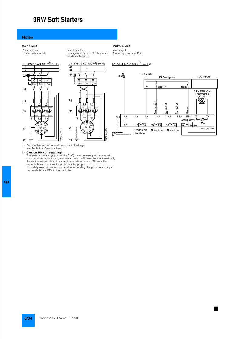
8122019 Arr Estado Solido
httpslidepdfcomreaderfullarr-estado-solido 3840
3RW Soft Starters
Notes
1) Permissible values for main and control voltagesee Technical Specifications
2) Caution Risk of restartingThe start command (eg from the PLC) must be reset prior to a resetcommand because a new automatic restart will take place automaticallyif a start command is active after the reset command This appliesespecially in case of motor protection trippingFor safety reasons we recommend incorporating the group error output(terminals 95 and 96) in the controller
Main circuit Control circuit
Possibility 4a Possibility 4b Possibility 4Inside-delta circuit Change of direction of rotation for
inside-delta circuitControl by means of PLC
13 14 23 24 33 34 95 9896+
T1 T2IN4IN3IN2IN1L-L+A1
A2
NPE
PEG1
NSB0_01498a
+24 V DC
M
F2
L1 1NPE AC 230 V 50 Hz1)
2)
R e s e t
Switch-onduration
No action
Group error
N o a c t i o n
N o a c t i o n
No action
PTC type A orThermoclick
M o t o r r i g h t
PLC outputs PLC inputs
Start Reset
7
8122019 Arr Estado Solido
httpslidepdfcomreaderfullarr-estado-solido 3940
Appendix
Conditions of sale and delivery
Terms and Conditions of Sale and Delivery
By using this catalog you can acquire hardware and softwareproducts described therein from the Siemens AG subject to the
following terms Please note The scope the quality and the con-ditions for supplies and services including software productsby any Siemens entity having a registered office outside of Ger-many shall be subject exclusively to the General Terms andConditions of the respective Siemens entity
For customers with a seat or registered office in theFederal Republic of Germany
The bdquoGeneral Terms of Paymentldquo as well as the bdquoGeneral Condi-tions for the Supply of Products and Services of the Electricaland Electronics Industryldquo shall apply
For software products the bdquoGeneral License Conditions for Soft-ware Products for Automation and Drives for Customers with aSeat or registered Office in Germanyldquo shall apply
For customers with a seat or registered office outside of
Germany The bdquoGeneral Terms of Paymentldquo as well as the bdquoGeneral Condi-tions for Supplies of Siemens Automation and Drives for Cus-tomers with a Seat or registered Office outside of Germanyldquo shallapply
For software products the bdquoGeneral License Conditions for Soft-ware Products for Automation and Drives for Customers with aSeat or registered Office outside of Germanyldquo shall apply
General
The prices are in 991404 (Euro) ex works exclusive packaging
The sales tax (value added tax) is not included in the pricesIt shall be debited separately at the respective rate according tothe applicable legal regulations
In addition to the prices of products which include silver plump
aluminum andor copper surcharges may be calculated if therespective limits of the notes are exceeded The respective note(eg source German newspaper bdquoHandesblattldquo in categorybdquodeutsche Edelmetalleldquo and bdquoMetallverarbeiterldquo) for silver (bdquover-arbeitetes Silberldquo) plump (bdquoBlei in Kabelnldquo) aluminum (bdquoAlumin-ium in Kabelnldquo) and copper (bdquoElektrolytkupferldquo bdquoDEL-Notizldquo) re-spectively of the day the order or rather the on call order isreceived is decisive for the calculation of the surcharges
Surcharges of copper shall be calculated for Drives at a note(bdquoDEL-Notizldquo) above EUR 22500 100 Kg and for chokes trans-formers above EUR 15000 100 kg
Surcharges shall be charged based on the quantities of the ma-terials which are contained in the relevant products
Prices are subject to change without prior notice We will debitthe prices valid at the time of delivery
The dimensions are in mm In Germany according to the Ger-man law on units in measuring technology data in inches onlyapply to devices for export
Illustrations are not binding
Insofar as there are no remarks on the corresponding pages- especially with regard to data dimensions and weights given -these are subject to change without prior notice
Comprehensive Terms and Conditions of Sale and Delivery areavailable free of charge from your local Siemens business officeunder the following Order Nos
bull 6ZB5310-0KR30-0BA0(for customers based in the Federal Republic of Germany)
bull 6ZB5310-0KS53-0BA0(for customers based outside of theFederal Republic ofGermany)
or download them from the Internethttpwwwsiemenscomautomationmall (Germany AampD Mall Online-Help System)
Export regulations
The products listed in this catalog price list may be subject toEuropean German andor US export regulations
Therefore any export requiring a license is subject to approvalby the competent authorities
According to current provisions the following export regulations
must be observed with respect to the products featured in thiscatalog price list
Even without a label or with an ldquoAL Nldquo or ldquoECCN Nldquo authoriza-tion may be required due to the final destination and purpose forwhich the goods are to be used
The deciding factors are the AL or ECCN export authorizationindicated on order confirmations delivery notes and invoices
Errors excepted and subject to change without prior notice
AampDVuLEn 060306
AL Number of the German Export List
Products marked other than ldquoNldquo require an exportlicenseIn the case of software products the export des-ignations of the relevant data medium must alsobe generally adhered to
Goods labeled with an ldquoAL not equal to Nldquo aresubject to a European or German export authori-zation when being exported out of the EU
ECCN Export Control Classification Number
Products marked other than ldquoNldquo are subject to a
reexport license to specific countriesIn the case of software products the exportdesignations of the relevant data medium mustalso be generally adhered to
Goods labeled with an ldquoECCN not equal to Nldquo aresubject to a US re-export authorization
_ _ _ _
8122019 Arr Estado Solido
httpslidepdfcomreaderfullarr-estado-solido 4040
8122019 Arr Estado Solido
httpslidepdfcomreaderfullarr-estado-solido 3940
Appendix
Conditions of sale and delivery
Terms and Conditions of Sale and Delivery
By using this catalog you can acquire hardware and softwareproducts described therein from the Siemens AG subject to the
following terms Please note The scope the quality and the con-ditions for supplies and services including software productsby any Siemens entity having a registered office outside of Ger-many shall be subject exclusively to the General Terms andConditions of the respective Siemens entity
For customers with a seat or registered office in theFederal Republic of Germany
The bdquoGeneral Terms of Paymentldquo as well as the bdquoGeneral Condi-tions for the Supply of Products and Services of the Electricaland Electronics Industryldquo shall apply
For software products the bdquoGeneral License Conditions for Soft-ware Products for Automation and Drives for Customers with aSeat or registered Office in Germanyldquo shall apply
For customers with a seat or registered office outside of
Germany The bdquoGeneral Terms of Paymentldquo as well as the bdquoGeneral Condi-tions for Supplies of Siemens Automation and Drives for Cus-tomers with a Seat or registered Office outside of Germanyldquo shallapply
For software products the bdquoGeneral License Conditions for Soft-ware Products for Automation and Drives for Customers with aSeat or registered Office outside of Germanyldquo shall apply
General
The prices are in 991404 (Euro) ex works exclusive packaging
The sales tax (value added tax) is not included in the pricesIt shall be debited separately at the respective rate according tothe applicable legal regulations
In addition to the prices of products which include silver plump
aluminum andor copper surcharges may be calculated if therespective limits of the notes are exceeded The respective note(eg source German newspaper bdquoHandesblattldquo in categorybdquodeutsche Edelmetalleldquo and bdquoMetallverarbeiterldquo) for silver (bdquover-arbeitetes Silberldquo) plump (bdquoBlei in Kabelnldquo) aluminum (bdquoAlumin-ium in Kabelnldquo) and copper (bdquoElektrolytkupferldquo bdquoDEL-Notizldquo) re-spectively of the day the order or rather the on call order isreceived is decisive for the calculation of the surcharges
Surcharges of copper shall be calculated for Drives at a note(bdquoDEL-Notizldquo) above EUR 22500 100 Kg and for chokes trans-formers above EUR 15000 100 kg
Surcharges shall be charged based on the quantities of the ma-terials which are contained in the relevant products
Prices are subject to change without prior notice We will debitthe prices valid at the time of delivery
The dimensions are in mm In Germany according to the Ger-man law on units in measuring technology data in inches onlyapply to devices for export
Illustrations are not binding
Insofar as there are no remarks on the corresponding pages- especially with regard to data dimensions and weights given -these are subject to change without prior notice
Comprehensive Terms and Conditions of Sale and Delivery areavailable free of charge from your local Siemens business officeunder the following Order Nos
bull 6ZB5310-0KR30-0BA0(for customers based in the Federal Republic of Germany)
bull 6ZB5310-0KS53-0BA0(for customers based outside of theFederal Republic ofGermany)
or download them from the Internethttpwwwsiemenscomautomationmall (Germany AampD Mall Online-Help System)
Export regulations
The products listed in this catalog price list may be subject toEuropean German andor US export regulations
Therefore any export requiring a license is subject to approvalby the competent authorities
According to current provisions the following export regulations
must be observed with respect to the products featured in thiscatalog price list
Even without a label or with an ldquoAL Nldquo or ldquoECCN Nldquo authoriza-tion may be required due to the final destination and purpose forwhich the goods are to be used
The deciding factors are the AL or ECCN export authorizationindicated on order confirmations delivery notes and invoices
Errors excepted and subject to change without prior notice
AampDVuLEn 060306
AL Number of the German Export List
Products marked other than ldquoNldquo require an exportlicenseIn the case of software products the export des-ignations of the relevant data medium must alsobe generally adhered to
Goods labeled with an ldquoAL not equal to Nldquo aresubject to a European or German export authori-zation when being exported out of the EU
ECCN Export Control Classification Number
Products marked other than ldquoNldquo are subject to a
reexport license to specific countriesIn the case of software products the exportdesignations of the relevant data medium mustalso be generally adhered to
Goods labeled with an ldquoECCN not equal to Nldquo aresubject to a US re-export authorization
_ _ _ _
8122019 Arr Estado Solido
httpslidepdfcomreaderfullarr-estado-solido 4040

8122019 Arr Estado Solido
httpslidepdfcomreaderfullarr-estado-solido 4040