aris.iaea.org to maintain a sub-critical array even in the event the building is flooded with...
TRANSCRIPT

Status report 81 - Advanced Passive PWR (AP 1000)
Overview
Full name Advanced Passive PWR
Acronym AP 1000
Reactor type Pressurized Water Reactor (PWR)
Coolant Light Water
Moderator Light water
Neutron spectrum Thermal Neutrons
Thermal capacity 3400.00 MWth
Electrical capacity 1200.00 MWe
Design status Under Construction
Designers Westinghouse
Last update 04-04-2011
Description
Introduction
The Westinghouse Advanced Passive PWR AP1000 is an 1100 MWe class PWR based closely on the AP600design. The AP1000 maintains most of the AP600 design configuration, and uses the AP600 components, proven inearlier Westinghouse PWRs or in special test programs, and licensing basis by limiting the changes to the AP600design to as few as possible. The AP1000 design includes advanced passive safety systems and extensive plantsimplifications to enhance the safety, construction, operation, and maintenance of the plant. The plant design utilizesproven technology, which builds on approximately 40 years of operating PWR experience. PWRs represent 74percent of all Light Water Reactors around the world, and the majority of these are based on Westinghouse PWRtechnology.
The AP1000 is designed to achieve a high safety and performance record. It is conservatively based on proven PWRtechnology, but with an emphasis on safety features that rely on natural forces. The safety systems use naturaldriving forces such as pressurized gas, gravity flow, natural circulation flow, and convection. The safety systems donot use active components (such as pumps, fans or diesel generators) and are designed to function withoutsafety-grade support systems (such as AC power, component cooling water, service water, HVAC). The number andcomplexity of operator actions required to control the safety systems are minimized; the approach is to eliminate theneed for operator action rather than automate it.
The AP1000 is designed to meet U.S. NRC deterministic safety criteria and probabilistic risk criteria with largemargins. Safety analysis has been completed and documented in the Design Control Document (DCD) andProbabilistic Risk Analysis (PRA). The extensive AP600 testing program, which has been shown to be applicable
to the AP1000 together with some additional tests, verifies that the plant’s innovative features will perform asdesigned and analyzed. PRA results predict a very low core damage frequency which meet the goals established foradvanced reactor designs, and a low frequency of release due to improved containment isolation and cooling and agreatly reduced probability of ex-vessel severe accident scenarios.
An important aspect of the AP1000 design philosophy focuses on plant operability and maintainability. TheAP1000 design includes features such as simplified system design to improve operability with a reduced number ofcomponents and associated maintenance requirements. In particular, the simplified AP1000 safety systems reducesurveillance requirements by enabling significantly simplified technical specifications.
Selection of proven components has been emphasized to ensure a high degree of reliability with a low maintenancerequirement. Component standardization reduces spare parts, minimizes maintenance, training requirements, andallows shorter maintenance durations. Built-in testing capability is provided for critical components.
Plant layout ensures adequate access for inspection and maintenance. Laydown space provides for staging ofequipment and personnel, equipment removal paths, and space to accommodate remotely operated service equipmentand mobile units. Access platforms and lifting devices are provided at key locations, as are service provisions suchas electrical power, demineralized water, breathing and service air, ventilation, and lighting.
The AP1000 design also incorporates radiation exposure reduction principles to keep worker dose as low asreasonably achievable (ALARA). Exposure length, distance, shielding, and source reduction are fundamental criteriathat are incorporated into the design.
Various features incorporated in the design to minimize construction time and total cost by eliminating componentsand reducing bulk quantities and building volumes include:
The integrated protection system, advanced control room, distributed logic cabinets, multiplexing, and fiberoptics, significantly reduce the quantity of cables, cable trays, and conduits;A stacked arrangement of the Class 1E battery, dc switchgear, integrated protection system, and the maincontrol rooms eliminate the need for the upper and lower cable spreading rooms that are required in currentgeneration PWR plants;The application of the passive safety systems replaces and/or eliminates many of the conventional mechanicalsafety systems typically located in Seismic Category I buildings in current generation PWR plants.
The AP1000 is designed with environmental consideration as a priority. The safety of the public and the powerplant workers, and the impact to the environment have been addressed as follows:
Operational releases have been minimized by design features;Aggressive, low dose goals for worker radiation exposure have been set and satisfied;Total radwaste volumes have been minimized;Other hazardous waste (non-radioactive) have been minimized.
The AP1000 has a well-defined design basis that has been confirmed through thorough engineering analyses andtesting. Some of the high-level design characteristics, and operational and safety goals of the plant are:
Net electrical power in the range of 1100 MWe; and a thermal power of 3415 MWt;Rated performance is achieved with up to 10% of the steam generator tubes plugged and with a maximum hotleg temperature of 610°F (321°C);Core design is robust with at least a 15% operating margin on core power parameters;Short lead time (five years from owner's commitment to commercial operation) and construction schedule (3years);No plant prototype is needed since proven power generating system components are used;Major safety systems are passive; they require no operator action for 72 hours after the most limitingaccidents, and core cooling is maintained for a protracted time without ac power;Predicted core damage frequency of 2.4E-07/yr is well below the 1E-05/yr utility requirement, and frequency

of significant release of 1.95E-08/yr is well below the 1E‑06/yr utility requirement;Standard design is applicable to anticipated sites in the U.S. and in other countries;Occupational radiation exposure expected to be below 0.7 man-Sv/yr (70 man-rem/yr);Core is designed for a 18-month fuel cycle;Refuelling outages can be conducted in 17 days or less;Plant design life is 60 years without replacement of the reactor vessel;Overall plant availability greater than 93%, including forced and planned outages; the goal for unplannedreactor trips is less than one per year;Leak-before-break on primary lines > 6-inches in diameter and on main steam lines;Seismic design based on 0.3g ground acceleration;Security enhanced with all safe shutdown equipment located in safety reinforced concrete Nuclear Islandbuildings;Meet EPRI-URD and EUR requirements;In-vessel retention of core debris following core melt provides a means to prevent containment failure andradioactive release to the environment due to ex-vessel severe accident phenomena;No reactor pressure vessel penetrations are located below the top of the core. This minimizess the possibilityof a loss of coolant accident which could lead to an extended core uncovery.
Description of the nuclear systems
2.1. Primary circuit and its main characteristics
The primary circuit of the AP1000 reactor retains most of the general design features of current designs, with addedevolutionary features to enhance the safety and maintainability of the system. The system consists of two heattransfer circuits (Figure 2.1-1) each with a single hot leg and two cold legs, a steam generator, and two reactorcoolant pumps installed directly onto the steam generator; eliminating the primary piping between pumps and steamgenerator. A simplified support structure for the primary systems reduces in-service inspections and improvesaccessibility for maintenance.
The reactor coolant system pressure boundary provides a barrier against release of radioactivity and is designed toprovide a high degree of integrity throughout operation of the plant.

FIG. 2.1-1 Isometric view of AP1000 NSSS
2.2. Reactor core and fuel design
The core, reactor vessel, and reactor internals of the AP1000 are similar to those of conventional Westinghouse PWRdesigns. The reactor core is comprised of 157, 14 feet (426.7 cm) long, 17´17 fuel assemblies and has severalimportant enhancements, all based on existing technology, that improve the performance characteristics of the design. The core incorporates the Westinghouse ROBUST fuel assembly design compared to the Vantage 5-H design of the
AP600and has at least 15 percent margin to departure from nucleate boiling (DNB), ZIRLOTM grids, removable topnozzles, and provides longer burnup.. The AP1000 core design and gravity driven boron addition from the coremakeup tanks increase safety margins for accident scenarios such as Anticipated Transients Without Scram.
The materials between the core and the pressure vessel that serve to attenuate neutrons originating in the core andgamma rays from both the core and structural components consist of the core shroud, core barrel, and the associatedreactor vessel downcomer water annuli.
The core consists of three radial regions that have different enrichments; the enrichment of the fuel ranges from 2.35 to
4.8% U235. The temperature coefficient of reactivity of the core is highly negative. The core is designed for a fuelcycle of 18 months with a 93% capacity factor, and region average discharge burnups as high as 60000 MWd/t.
The AP1000 uses reduced-worth control rods (termed "gray" rods) to achieve daily load follow without requiringchanges in the soluble boron concentration. The use of gray rods, in conjunction with an automated load followcontrol strategy, eliminates the need for processing thousands of gallons of water per day to change the reactor coolantsoluble boron concentration. As a result, there is no need for a boron processing/recycle system and the waste liquidsystem is simplified since letdown flow and processing are greatly decreased. With the exception of the neutron

absorber materials used, the design of the gray rod assembly is identical to that of a normal control rod assembly.
2.3. Fuel handling and transfer systems
Refuelling is performed in the same way as for current plants. After removing the vessel head, fuel handling takesplace from above, using the refuelling machine to configure the core for the next cycle.
2.3.1 New fuel storage
New fuel is stored in a high-density rack which includes integral neutron absorbing material to maintain the requireddegree of sub-criticality. The rack is designed to store fuel of the maximum design basis enrichment. The new fuelrack includes storage locations for 72 fuel assemblies. Minimum separation between adjacent fuel assemblies issufficient to maintain a sub-critical array even in the event the building is flooded with unborated water, fireextinguishing aerosols, or during any design basis event.
2.3.2 S pent fuel storage
Spent fuel is stored in high density racks which include integral neutron absorbing material to maintain the requireddegree of sub-criticality. The racks are designed to store fuel of the maximum design basis enrichment. The spentfuel storage racks include storage locations for 884 fuel assemblies and five defective fuel assemblies. The design ofthe racks is such that a fuel assembly can not be inserted into a location other than a location designed to receive anassembly.
2.4. Primary components
2.4.1 Reactor pressure vessel
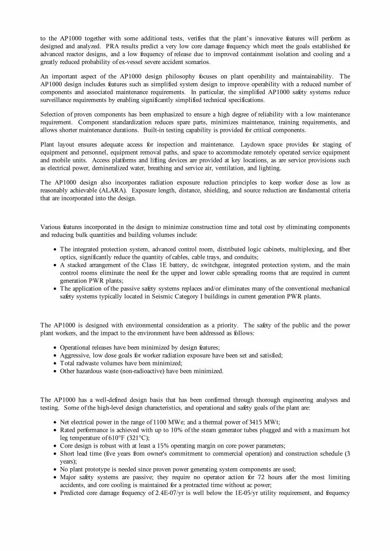
The reactor vessel (Figure 2.4-1) is the high-pressure containment boundary used to support and enclose the reactorcore. The vessel is cylindrical, with a hemispherical bottom head and removable flanged hemispherical upper head.
The reactor vessel is approximately 39.5 feet (12.0 m) long and has an inner diameter at the core region of 159 inches(4.039 m). Surfaces, which can become wetted during operation and refuelling, are clad with stainless steel welded
overlay. The AP1000 reactor vessel design pressure and temperature is 2500 psia (17.1 MPa) and 650°F (343oC)respectively, and it has a 60 year design life. As a safety enhancement, there are no reactor vessel penetrations belowthe top of the core. This feature is part of the AP1000 severe accident strategy to retain core debris inside the reactorvessel following postulated scenarios that result in core melt. The core is positioned low in the vessel to minimizereflood time following postulated large LOCAs and also supports in-vessel retention of core debris following coremelt.
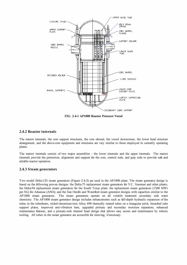
FIG. 2.4-1 AP1000 Reactor Pressure Vessel
2.4.2 Reactor internals
The reactor internals, the core support structures, the core shroud, the vessel downcomer, the lower head structurearrangement, and the above-core equipment and structures are very similar to those employed in currently operatingplants.
The reactor internals consist of two major assemblies - the lower internals and the upper internals. The reactorinternals provide the protection, alignment and support for the core, control rods, and gray rods to provide safe andreliable reactor operation.
2.4.3 S team generators
Two model Delta-125 steam generators (Figure 2.4-2) are used in the AP1000 plant. The steam generator design isbased on the following proven designs: the Delta-75 replacement steam generators for V.C. Summer and other plants;the Delta-94 replacement steam generators for the South Texas plant; the replacement steam generators (1500 MWtper SG) for Arkansas (ANO); and the San Onofre and Waterford steam generator designs with capacities similar to theAP1000 steam generators. The steam generators operate on all volatile treatment secondary side waterchemistry. The AP1000 steam generator design includes enhancements such as full-depth hydraulic expansion of thetubes in the tubesheets, nickel‑chromium‑iron Alloy 690 thermally treated tubes on a triangular pitch, broached tubesupport plates, improved anti-vibration bars, upgraded primary and secondary moisture separators, enhancedmaintenance features, and a primary-side channel head design that allows easy access and maintenance by robotictooling. All tubes in the steam generator are accessible for sleeving, if necessary.
FIG. 2.4-2 AP1000 Steam generator
2.4.4 Pressurizer
The AP1000 pressurizer is of conventional design, based on proven technology. The pressurizer volume is 2100 ft3
(59.5 m3). The large pressurizer minimizes challenges to the plant and operator during transients by providingincreased operating margins resulting in a more reliable plant with fewer reactor trips. The large pressurizer size alsoeliminates the need for fast-acting power-operated relief valves, which are a possible source of RCS leakage andmaintenance.
2.4.5 Reactor coolant pumps
The AP1000 reactor coolant pumps are high-inertia, highly-reliable, low-maintenance, hermetically sealed pumpsthat circulate the reactor coolant through the reactor core, loop piping, and steam generators. The AP1000 pump isbased on the AP600 canned-motor pump design modified to provide more flow and head, and a longer flow coastdown time. An alternative seal-less, wet-winding motor design option can also be adopted.
The motor size is minimized through the use of a variable speed controller to reduce motor power requirementsduring cold coolant conditions, and to allow the use of identical pumps in countries with a 50Hz electrical grid. Two pumps are mounted directly in the channel head of each steam generator. This configuration eliminates thecrossover leg of coolant loop piping between the steam generator and the pump, thereby reducing the loop pressuredrop and simplifying the foundation and support system for the steam generator, pumps, and loop piping. Theelimination of the cross-over piping also reduces the potential for uncovering of the core by eliminating the need toclear the loop seal during a small LOCA. The reactor coolant pumps have no seals, eliminating the potential for sealfailure LOCA, which significantly enhances safety and reduces pump maintenance. The pumps use an internalflywheel to increase the pump rotating inertia and thereby providing a slower rate-of-flow coastdown to improve corethermal margins following the loss of electric power. Testing has validated the manufacturability and operability ofthe pump flywheel assembly, and testing of the initial production pump is in progress.
2.4.6 Main coolant lines
The reactor coolant system (RCS) piping is configured with two identical main coolant loops, each employing asingle 31-inch (790 mm) inside diameter hot leg pipe to transport reactor coolant to a steam generator and two22-inch (560 mm) inside diameter cold leg pipes (one per pump) to transport reactor coolant back to the reactorvessel to complete the circuit. The two reactor coolant pump suction nozzles are welded directly to the outlet nozzleson the bottom of the steam generator channel head.
The RCS loop layout contains several important features that provide for a significantly simplified and safer design. The reactor coolant pumps mount directly on the channel head of each steam generator, which allows the pumps andsteam generator to use the same structural support, greatly simplifying the support system and providing more spacefor maintenance. The combined steam generator/pump vertical support is a single pinned column extending from thefloor to the bottom of the channel head. The steam generator channel head is a one-piece forging with manufacturingand inspection advantages over multi-piece, welded components. The integration of the pump suction into thebottom of the steam generator channel head eliminates the crossover leg of coolant loop piping, thus avoiding thepotential for core uncovery due to loop seal venting during a postulated small cold leg break LOCA event.
The simplified, compact arrangement of the RCS also provides other benefits. The two cold leg lines of the twomain coolant loops are identical (except for instrumentation and small line connections) and include bends to providea low-resistance flow path and flexibility to accommodate the expansion difference between the hot and cold leg pipes. The piping is forged and then bent, which reduces costs and in-service inspection requirements. The loopconfiguration and material selection yield sufficiently low pipe stresses so that the primary loop and large auxiliarylines meet leak-before-break requirements. Thus, pipe rupture whip restraints are not required, greatly simplifying thedesign and providing enhanced access for maintenance. The simplified RCS loop configuration also allows for asignificant reduction in the number of snubbers and supports. Field service experience and utility feedback haveindicated the high desirability of these features.
2.5.Reactor auxiliary systems
2.5.1 Chemical and volume control system
The chemical and volume control system (CVS) consists of regenerative and letdown heat exchangers, demineralizersand filters, makeup pumps, tanks, and associated valves, piping, and instrumentation, and is designed to perform thefollowing major functions:
Purification ‑ maintains reactor coolant purity and activity level within acceptable limits;Reactor coolant system inventory control and makeup ‑ maintains the required coolant inventory in thereactor coolant system; maintain the programmed pressurizer water level during normal plant operations;Chemical shim and chemical control ‑ maintains reactor coolant chemistry during plant start-ups, normalboron dilution for plant start-up and to compensate for fuel depletion, shutdown boration, and controls thereactor coolant system pH by maintaining the proper level of lithium hydroxide;Oxygen control ‑ provides the means for maintaining the proper level of dissolved hydrogen in the reactorcoolant during power operation and for achieving the proper oxygen level prior to plant start-up after eachshutdown;Filling and pressure testing of the reactor coolant system – provides the means for filling and pressuretesting of the reactor coolant system. The chemical and volume control system does not perform hydrostatictesting of the reactor coolant system, but provides connections for a temporary hydrostatic test pump;Borated makeup to auxiliary equipment ‑ provides makeup water to the primary side systems, whichrequires borated reactor grade water;Pressurizer Auxiliary Spray - provides pressurizer auxiliary spray water for depressurization.
2.5.2 Normal residual heat removal system
This system consists of two mechanical trains of equipment, each comprising one pump and one heat exchanger. The system also includes the piping, valves and instrumentation necessary for system operation. The major

functions are:
Shutdown heat removal - removes residual and sensible heat from the core and the reactor coolant systemduring plant cooldown and shutdown operations. The system provides reactor coolant system cooldown from350 to 120°F (177 to 48.9°C) within 96 hours after shutdown and maintains the reactor coolant temperatureat or below 120°F.Shutdown purification ‑ provides reactor coolant system and refuelling cavity purification flow to thechemical and volume control system during refuelling operations.In-containment refuelling water storage tank (IRWST) cooling– provides cooling to the IRWST to limitthe IRWST water temperature to less than 212°F (100°C) during extended operation of the passive residualheat removal system and to not greater than 120°F during normal operation.Low pressure reactor coolant system makeup and cooling - provides low pressure makeup to the reactorcoolant system from the cask loading pit and then from the IRWST thus providing additional margin for corecooling.Low temperature overpressure protection - provides low temperature overpressure protection for the reactorcoolant system during refuelling, start-up, and shutdown operations.Long-term, post-accident containment inventory makeup flow path - provides a flow path for long termpost-accident makeup to the reactor containment water inventory to make up for containment leakage.Post-accident recovery ‑ remover heat from the core and the reactor coolant system following successfulmitigation of an accident by the passive core cooling systemSpent fuel pool cooling - provides backup cooling of the spent fuel pool.
2.5.3 S pent Fuel Pool Cooling S ystem
This system is designed to remove decay heat from the stored fuel assemblies by removing heat from the water in thespent fuel pool. This is done by pumping the high temperature water from within the fuel pool through a heatexchanger, and then returning cooler water to the pool. A secondary function of this system is clarification andpurification of the water in the spent fuel pool, the transfer canal, and the refuelling water. The major functions of thesystem are:
Spent fuel pool cooling ‑ removes heat from the water in the spent fuel pool during all plant operations tomaintain the pool water temperature within acceptable limits.Spent fuel pool purification ‑ provides purification and clarification of the spent fuel pool water duringoperation.Refuelling cavity purification ‑ provides purification of the refuelling cavity during refuelling operations.Water transfers ‑ transfers water between the in‑containment refuelling water storage tank (IRWST) and therefuelling cavity during refuelling operations.In-containment refuelling water storage tank purification ‑ provides purification and cooling of theIRWST during normal operation.
2.6.Operating characteristics
The plant control scheme is based on the "reactor follows plant loads." A grid fluctuation can be compensated forthrough turbine control valves in case of a frequency drop. A decrease in pressure at the turbine would require anincrease in reactor power.
The AP1000 is designed for load-follow operation for up to 90 percent of the fuel cycle using the MSHIM(Mechanical Shim) mode of operation. The benefit of MSHIM load follow operation is that the critical boronconcentration remains constant during load follow, eliminating the generation of waste water. The axial power shapecan be maintained throughout the load-follow sequence while simultaneously maintaining a constant boronconcentration. As a result, MSHIM operation does not generate severe axial xenon oscillations and radial powerdistributions that would lead to violations of FQ and departure from nucleate boiling ratio (DNBR) limits.
More generally, the AP1000 has extensive ability to meet grid load demands and is designed to withstand a series ofoperational occurrences without the generation of a reactor trip or actuation of the safety related passive engineered
safety systems. The logic and setpoints for the Nuclear Steam Supply System control systems are developed in orderto meet the following operational transients without reaching any of the protection system setpoints.
± 5%/minute ramp load change within 15% and 100% power± 10% step load change within 15% and 100% power100% generator load rejection100-50-100% power level daily load follow over 90% of the fuel cycle lifeGrid frequency changes equivalent to 10% peak-to-peak power changes at 2%/minute rate20% power step increase or decrease within 10 minutesLoss of a single feedwater pump
Description of safety concept
3.1. Safety requirements and design philosophy
The AP1000 design provides multiple levels of defense for accident mitigation (defense-in-depth), resulting inextremely low core damage probabilities while minimizing the occurrences of containment flooding, pressurization,and heat-up. Defense-in-depth is integral to the AP1000 design, with multiple plant features capable of providingsome degree of defense of plant safety. Six aspects of the AP1000 design contribute to defense-in-depth:
Stable Operation: In normal operation, the most fundamental level of defense-in-depth ensures that the plantcan be operated stably and reliably. This is achieved by the selection of materials, by quality assuranceduring design and construction, by well-trained operators, and by an advanced control system and plantdesign that provide substantial margins for plant operation before approaching safety limits.
Physical Plant Boundaries ; One of the most recognizable aspects of defense-in-depth is the protection ofpublic safety through the physical plant boundaries. Releases of radiation are directly prevented by the fuelcladding, the reactor coolant system pressure boundary, and the containment pressure boundary.
Passive Safety-Related Systems: The AP1000 safety-related systems and equipment are sufficient toautomatically establish and maintain core cooling and containment integrity for an significant period of timefollowing design basis events assuming the most limiting single failure, no operator action, and with noonsite and offsite ac electrical power sources.
Diversity within the Safety-Related Systems: An additional level of defense is provided through the diversemitigation functions within the passive safety‑related systems. This diversity exists, for example, in theresidual heat removal function. The passive residual heat removal heat exchanger (PRHR HX) is the passivesafety feature for removing decay heat from the RCS during a transient. In case of multiple failures in thePRHR HX flow path, defense-in-depth is provided by gravity injection of borated water into the RCS andoperation of the automatic depressurization functions of the passive core cooling system. This establishespassive feed and bleed which also results in the removal of core decay heat as well as RCS cooldown anddepressurization.
Non-safety Systems: The next level of defense-in‑depth is the availability of certain non-safety systems forreducing the potential for events leading to core damage. For more probable events, these highly reliablenon-safety systems automatically actuate to provide a first level of defense to reduce the likelihood ofunnecessary actuation and operation of the passive safety-related systems.
Containing Core Damage: The AP1000 design provides the operators with the ability to drain the IRWSTwater into the reactor cavity in the event that the core has uncovered and is melting. This prevents reactorvessel failure and subsequent relocation of molten core debris into the containment. Retention of the debris inthe vessel provides high confidence that containment failure and radioactive release to the environment willnot occur due to ex-vessel severe accident phenomena. (See Section 3.3 for additional discussion regardingin-vessel retention.)
AP1000 defense-in-depth features enhance safety such that no severe release of fission products is predicted to occurfrom an initially intact containment for more than 100 hours after the onset of core damage, assuming no actions forrecovery.This provides time for performing accident management actions to mitigate the accident and prevent
containment failure. The frequency of severe release as predicted by PRA is 1.95 x 10⁻⁸ per reactor year, which ismuch lower than for conventional plants.
3.2. Safety systems and features (active, passive, and inherent)
The AP1000 uses passive safety systems to improve the safety of the plant and to satisfy NRC safety criteria. Thepassive safety systems are superior to conventional plant active safety system designs providing significant andmeasurable improvements in plant simplification, safety, reliability, and investment protection. The passive safetysystems require no operator actions for a significant period of time to mitigate limiting design basis accidents. Thesesystems use only natural forces such as gravity, natural circulation, and compressed gas to make the systems work. No pumps, fans, diesels, chillers, or other active machinery are used. A few simple valves align and automaticallyactuate the passive safety systems. To provide high reliability, these valves, where possible, are designed to actuateto their safety positions upon loss of power or upon receipt of a safety actuation signal. Where necessary, dc electricalpower supplied from four independent trains of batteries is used to support instrumentation, actuation, and dcpowered valve functions.
The passive safety systems do not require the large network of active safety support systems (ac electrical power,HVAC, cooling water, and the associated seismic buildings to house these components) that are needed in typicalnuclear plants. As a result, support systems no longer must be safety class, and they are simplified or eliminated.
The AP1000 passive safety-related systems and functions include:
The passive core cooling system (PXS)The passive containment cooling system (PCS)The main control room emergency habitability system (VES)Containment isolation function (CNS)Passive 1E dc power system (IDS)Passive containment sump water pH controlPassive cooling of 1E instrumentation and control areas by the plant structure
These passive safety systems provide a major enhancement in plant safety and investment protection as comparedwith conventional plants. They establish and maintain core cooling and containment integrity for a significant time,with no operator or ac power support requirements. The passive systems are designed to meet the single-failurecriteria, and PRAs are used to verify their reliability.
The AP1000 (and AP-600) passive safety systems are significantly simpler than typical PWR safety systems sincethey contain significantly fewer components, reducing the required tests, inspections, and maintenance. They requireno active support systems, and their readiness is easily monitored.
3.2.1 Emergency core cooling system
The passive core cooling system (PXS) (Figure 3.2-1) provides RCS heat removal, injection, and boration. Thus thePXS protects the plant against transient events and reactor coolant system (RCS) leaks and ruptures of various sizesand locations. The PXS provides the safety functions of core residual heat removal, safety injection, and

depressurization. Safety analyses (using U.S. NRC-approved codes) demonstrate the effectiveness of the PXS inprotecting the core following various RCS break events. There is no core uncovery for an 8‑inch (200 mm) directvessel injection line and the PXS provides approximately a 363°F (202°C) margin to the maximum peak cladtemperature limit following a double-ended rupture of a main reactor coolant pipe.
3.2.2 S afety injection and depressurization
The PXS uses three passive sources of water to maintain core cooling through safety injection. These injectionsources include the core makeup tanks (CMTs), the accumulators, and the in-containment refueling water storage tank(IRWST). These injection sources are directly connected to two nozzles on the reactor vessel so that no injectionflow can be spilled for the main reactor coolant pipe break cases.
Long-term injection water is provided by gravity from the IRWST, which is located in the containment just abovethe RCS loops. Normally, the IRWST is isolated from the RCS by squib valves. The tank is designed foratmospheric pressure, and therefore, the RCS must be depressurized before injection can occur.
The depressurization of the RCS is automatically controlled to reduce pressure to about 12 psig (0.18 MPa) whichallows IRWST injection by gravity. The PXS depressurizes the RCS using the four stages of the ADS to permit arelatively slow, controlled RCS pressure reduction.
3.2.3 Passive residual heat removal
The PXS includes a 100% capacity passive residual heat removal heat exchanger (PRHR HX), which is connectedthrough inlet and outlet lines to RCS loop 1. The PRHR HX is designed to match the core decay heat at 15minutes after reactor shutdown. Following a loss of main feed water, with no credit for actuation of the startup feedwater pumps and with safety analysis conservatisms; the PRHR HX heat removal rate, together with the steamgenerator secondary side inventory, is sufficient to maintain the RCS fluid subcooled and maintain acceptablepressurizer pressure and level increase. Thus the PRHR HX protects the plant against transients that upset thenormal steam generator feed water and steam systems and satisfies the safety criteria for loss of feedwater, feedwaterand steam line breaks.
The IRWST provides the heat sink for the PRHR HX. The IRWST water volume is sufficient to absorb decay heatfor more than 1 hour before the water begins to boil. Once boiling starts, steam is vented from the IRWST to thecontainment. This steam condenses on the inside surface of the steel containment vessel and, after collection, drainsby gravity back into the IRWST. The PRHR HX and the passive containment cooling system provide decay heatremoval capability with no operator action required.

FIG. 3.2-1. AP1000 Passive Core Cooling System
3.2.4 Passive containment cooling
The passive containment cooling system (PCS) (Figure 3.2-2) provides the safety-related ultimate heat sink for theplant. As demonstrated by computer analyses and extensive test programs, the PCS effectively cools the containmentfollowing an accident such that the pressure is rapidly reduced and the design pressure is not exceeded.
The steel containment vessel provides the heat transfer surface for the removal of heat from inside the containment tothe atmosphere. Heat is removed from the containment vessel outside surface by continuous natural circulation flowof air. During an accident, the air cooling is supplemented by evaporation of water which drains by gravity from atank on top of the containment shield building.
Calculations have predicted the AP1000 to have a significantly reduced large release frequency following a severeaccident core damage scenario, relative to conventional plant designs. Following an initiating transient event, thecontainment stays below design pressure for at least 24 hours with only the normal PCS air cooling and without thesupplemental heat removal of the water. The containment pressure stays well below the predicted failure pressure forat least 24 hours following a LOCA initiating event with no credit for water being applied to the outside containmentsurface. Other factors include improved containment isolation and reduced potential for LOCAs outside ofcontainment. This improved containment performance supports the technical basis for simplification of offsiteemergency planning.

FIG. 3.2-2 AP1000 Passive containment cooling system
3.2.5 Main control room emergency habitability
The main control room emergency habitability system (VES) provides fresh air, cooling, and filtration for the maincontrol room (MCR) following a plant accident. Operation of the VES is automatically initiated upon receipt of ahigh MCR radiation signal, which isolates the normal control room ventilation path and initiates pressurization. Following system actuation, all functions are completely passive. The VES air supply is contained in a set ofcompressed air storage tanks. The VES also maintains the MCR at a slight positive pressure, to minimize theinfiltration of airborne contaminants from the surrounding areas.
3.2.6 Containment isolation
AP1000 containment isolation is significantly improved over that of conventional PWRs. One major improvementis the large reduction in the number of penetrations. Furthermore, the number of normally open penetrations isreduced by 60 percent. There are no penetrations required to support post-accident mitigation functions (the cannedmotor reactor coolant pumps do not require seal injection, the passive residual heat removal and passive safetyinjection features are located entirely inside containment, and the passive containment cooling system operatesoutside the containment).
3.2.7 Long-term accident mitigation
A major safety advantage of the AP1000 versus current-day PWRs is that long-term accident mitigation ismaintained by the passive safety systems for 3 days without operator action and without reliance on offsite or onsiteac power sources. For the limiting design basis accidents, the core coolant inventory in the containment forrecirculation cooling and boration of the core is sufficient to last for at least 30 days, even if inventory is lost at thedesign basis containment leak rate. The passive containment cooling function operates without operator action for 3days after initiation, and then requires limited actions to extend its operation.
3.3. Severe accidents (beyond design basis accidents)

3.3.1 In-vessel retention of molten core debris
In-vessel retention (IVR) of molten core debris via water cooling of the external surface of the reactor vessel is aninherent severe accident management feature of the AP1000 passive plant. During postulated severe accidents, theaccident management strategy to flood the reactor cavity with IRWST water and submerge the reactor vessel has beendemonstrated to prevent vessel failure in the AP1000 PRA. The water cools the external surface of the vessel andprevents molten debris in the lower head from failing the vessel wall and relocating into the containment. Retainingthe debris in the reactor vessel protects the containment integrity by preventing ex‑vessel severe accident phenomena,such as ex-vessel steam explosion and core-concrete interaction, which have large uncertainties with respect tocontainment integrity.
The passive plant is uniquely suited to in-vessel retention because it contains features that promote external coolingof the reactor vessel. Figure 3.3-1 provides a schematic of the AP1000 reactor vessel, vessel cavity, vessel insulationand vents configuration that promotes IVR. These features include:
The reliable multi-stage reactor coolant system (RCS) depressurization system (utilizing redundent anddiverse valves) results in low stresses on the vessel wall after the RCS pressure is reduced.The vessel lower head has no vessel penetrations to provide a failure mode for the vessel other than creepfailure of the wall itself.The reactor cavity can be flooded to submerge the vessel above the coolant loop elevation with waterintentionally drained from the in-containment refuelling water storage tank.The reactor vessel insulation design concept provides an engineered pathway for water cooling of the vesselouter surface and for venting steam from the reactor cavity.
The results of the AP1000 IVR testing and analysis demonstrate that, with the AP1000 insulation designed toincrease the cooling limitation at the lower head surface and the cavity adequately flooded, the AP1000 providessignificant margin-to-failure for IVR via external reactor vessel cooling.
FIG. 3.3-1. AP1000 Configuration to Promote IVR of Molten Core Debris
Proliferation resistance
AP1000 does not present any unique issues relative to other LWRs with regards to proliferation and commercialnuclear power plants. Principal materials of concern in the nuclear weapons production cycle include highly enricheduranium (HEU) and plutonium. Uranium as mined from the earth poses no risk of proliferation. Before its use in

reactors, mined uranium must undergo an enrichment process that concentrates isotopes necessary for powerproduction. This process creates low enriched uranium (LEU) through a lengthy, complex and expensive process. Itis impossible to create a nuclear weapon from LEU.
However, analysts are mindful that the same enrichment facilities used to create LEU may have the capability toconvert natural uranium into highly enriched uranium. Nuclear reactors, once in operation, produce plutonium as aby product. However, the separation of plutonium contained in used fuel pellets requires complex chemicalreprocessing. Like enrichment, reprocessing calls for a highly sophisticated infrastructure.
Safety and security (physical protection)
The design and layout of AP1000 has taken security design considerations into account throughout the plant’sdetailed design development. AP1000’s design and configuration inherently protects the plant against human inducedmalevolent external impacts and insider action. AP1000’s physical security system is designed in accordance withthe applicable U.S. regulations. A detailed security analysis of the AP1000’s physical security system design againstthe Design Basis Threat, as defined by the U.S. NRC, has been completed and concludes AP1000 is designed suchthat it can, with high assurance, be protected against malevolent acts of sabotage.
The difference between the design of AP1000 and that of a conventional PWR represents a significant reduction invulnerability to a wide range of security threats. The AP1000 physical design has a number of features thatsignificantly reduce the plant’s vulnerability to an attempted act of radiological sabotage. These include thefollowing:
The use of passive safety features that do not require ac power or cooling water supplies inherently reduces theplant vulnerabilities. In addition the important passive features that provide reactor shutdown, decay heatremoval and containment isolation are fail safe such that even the total loss of the plant protectioninstrumentation system and dc power could be tolerated in a security event.All exterior and a large number of interior walls that house equipment important to safety consist of at least2’-0” thick concrete walls. These walls offer a significant deterrent to penetration. The design alsoincorporates several large structural modules within the Auxiliary Building. The module walls are designedwith inner and outer steel plates and are filled with concrete. Such a design is inherently hardened againstattempted penetration including the crash of either civilian or military aircraft.The number of entry points is minimized. The relatively small number of doors, their access paths, and theirproximity to one another allow for the development of an effective protective strategy. The design incorporates a robust vehicle barrier system that is located at a safe standoff distance. Fencing is employed to establish a perimeter boundary at a sufficient distance such that under normalcircumstances, security response force personnel are able to identify and engage a potential land based assault. An intrusion detection system is employed adjacent to the protected area boundary fencing to provideindication of unauthorized attempts to enter the protected area.A closed circuit television network is used to provide remote monitoring of the protected area boundary.An access control system is utilized to permit only properly authorized personnel into designated areas of thefacility.Both a central and a secondary alarm station are incorporated within the design of AP1000.The walls, floors, ceilings, doors, and windows of the main control room are bullet resistant.A dedicated security computer system is used for monitoring and control of functions related to the physicalcontrol of AP1000.Security lighting is provided at a level to support the security monitoring functions for certain locations.
Description of turbine-generator systems
6.1. Turbine generator plant
The AP1000 turbine generator is a power conversion system designed to change the thermal energy of the steamflowing through the turbine into rotational mechanical work, which rotates a generator to provide electrical power.

The turbine‑generator is designated as a TC6F 52 inch (1.32 m) last‑stage blade unit consisting of turbines, agenerator, external moisture separator/reheaters, controls, and auxiliary subsystems.
The turbine is a 1,800 rpm (1,500 rpm for 50 HZ applications), tandem‑compound, six‑flow, reheat unit with 52inch (1.32 m) last‑stage blades (TC6F 52‑inch, 1.32 m LSB). The high‑pressure turbine element includes onedouble‑flow, high‑pressure turbine. The low‑pressure turbine elements include three double‑flow, low‑pressureturbines and two external moisture separator/reheaters (MSRs) with two stages of reheating. The single direct‑drivengenerator is hydrogen gas and de-ionized water cooled and rated at 1375 MVA at 0.90 PF. Other related systemcomponents include a complete turbine‑generator bearing lubrication oil system, a digital electro-hydraulic (D-EHC)control system with supervisory instrumentation, a turbine steam sealing system (refer to subsection 10.4.3),overspeed protective devices, turning gear, a stator cooling water system, a generator hydrogen and seal oil system, agenerator CO2 system, a rectifier section, an excitation transformer, and a voltage regulator.
The turbine generator is intended for base load operation but also has load follow capability. The mechanical designof the turbine root and rotor steeple attachments uses optimized contour to significantly reduce operational stresses. Steam flow to the high-pressure turbine is controlled by two floor-mounted steam chests. Each contains twothrottle/stop valve assemblies, and two load-governing valves.
The condenser and circulating water systems have been optimized. For sites using cooling towers, the condenser is athree-shell, multi-pressure unit with one double-flow, low-pressure turbine exhausting into the top of each shell. Forsites with direct cooling, the condenser is a single pressure, single pass unit.
The turbine‑generator and associated piping, valves, and controls are located completely within the turbine building. There are no safety‑related systems or components located within the turbine building. The probability of destructive
overspeed condition and missile generation, assuming the recommended inspection frequency, is less than 10-5/yr. Turbine orientation minimizes potential interaction between turbine missiles and safety-related structures andcomponents. The turbine‑generator components and instrumentation associated with turbine‑generator overspeedprotection are accessible under operating conditions.
6.2. Condensate and feedwater systems
The condensate and feedwater system supplies the steam generators with heated feedwater in a closed steam cycleusing regenerative feedwater heating. The condensate and feedwater system is composed of the condensate system,the main feedwater system, and portions of the steam generator system. The condensate system collects condensedsteam from the condenser and pumps condensate forward to the deaerator. The feedwater system takes suction fromthe deaerator and pumps feedwater forward to the steam generator system utilizing high-pressure main feedwaterpumps. The steam generator system contains the safety-related piping and valves that deliver feedwater to the steamgenerators. The condensate and feedwater systems are located within the turbine building, and the steam generatorsystem is located within the auxiliary building and containment.
The main feedwater system includes three single speed motor driven feedwater pumps which operate in parallel andtake suction from their associated feedwater booster pump. The discharge from the main feedwater pumps is suppliedto the high-pressure feedwater heater and then to the steam generator system.
The feedwater train consists of three strings of low‑pressure heaters, each string consisting of a No. 1 and No. 2low‑pressure heater; two strings of low-pressure heaters No. 3 and No. 4; the No. 5 open low pressure heater(deaerator); two of the three parallel booster/main feedwater pumps; and two strings of high‑pressure heaters, No. 6and No. 7. Feedwater is pumped to the plant’s two steam generators through each generator’s respective flowelement, control valve, feedwater isolation valve, and check valve. The balance of the plant’s feedwater flow isprovided by drains from the main steam system moisture separator reheater, drains from the No. 6 and No. 7feedwater heaters, and steam condensed in the deaerator. These flows are collected in the deaerator and pumpedforward in the feedwater path. A portion of the condensate flow downstream of the condensate polishers is diverted toprovide cooling to the steam generator blowdown system heat exchangers before returning to the main condensateflow at the deaerator.
The condenser hotwell and deaerator storage capacity allows margin in the design. This margin, coupled with three50 percent condensate pumps, provides greater flexibility and the ability for an operator to control feedwater and

condensate transients.
Electrical and I&C systems
7.1. I&C Systems
The I&C system design for AP1000 integrates individual systems using similar technology. The heart of the systemis the portion used for plant protection and for operation of the plant.
The integrated AP1000 I&C system provides the following benefits:
Control wiring is reduced by 80%Cable spreading rooms are eliminatedMaintenance is simplifiedPlant design changes have little impact on I&C designAccurate, drift-free calibration is maintainedOperating margins are improved.
The AP1000 man-machine interfaces have been simplified compared to existing plants. The probability of operatorerror is reduced and operations, testing, and maintenance are simplified. An automatic signal selector in the controlsystem selects from a redundant sensor for control inputs in lieu of requiring manual selection by the control boardoperator. Accident monitoring and safety parameters are displayed on safety qualified displays with a coordinated setof graphics generated by the qualified data processor. The major benefits of the improved man-machine interfaces are:
Reduced quantity of manual actions is requiredReduced quantity of data is presented to operatorNumber of alarms is reducedImproved quality of data is presented to operatorData is interpreted for the operator by system computerMaintenance is simplified.
7.1.1. Design concept, including control room
The AP1000 instrumentation and control architecture (illustrated in Figure 7.1.1-1) is arranged in a hierarchicalmanner to provide a simplified structured design that is horizontally and vertically integrated.

FIG. 7.1.1-1. AP1000 Instrumentation and Control Architecture
Above the monitor bus are the systems that facilitate the interaction between the plant operators and the I&C. Theseare the operations and control center system (OCS) and the data display and monitoring system (DDS). Below themonitor bus are the systems and functions that perform the protective, control, and data monitoring functions. Theseare the protection and safety monitoring system (PMS) (Section 4.10.4.2) the plant control system (PLS), the specialmonitoring system (SMS), and the in-core instrumentation system (IIS).
The PLS has the function of establishing and maintaining the plant operating conditions within prescribed limits. The control system improves plant safety by minimizing the number of situations for which protective response isinitiated and it relieves the operator from routine tasks.
The purpose of the diverse actuation system (DAS) is to provide a diverse means of initiating the reactor trip andemergency safety features. The hardware and software used to implement the DAS are different from the hardware andsoftware used to implement the protection and safety monitoring system. The DAS is included to meet theanticipated transient without (reactor) trip (ATWT) rule and to reduce the probability of a severe accident resultingfrom the unlikely coincidence of a transient and common mode failure of the protection and safety monitoring. Theprotection and safety monitoring system is designed to prevent common mode failures; however, in thelow-probability case of a common mode failure, the DAS provides diverse protection.
7.1.1.1 Main control room
The operations and control centers system includes the complete operational scope of the main control room, theremote shutdown workstation, the waste processing control room, and partial scope for the technical support center. With the exception of the control console structures, the equipment in the control room is part of the other systems(for example, protection and safety monitoring system, plant control system, data and display processing system). The conceptual arrangement of the main control room is shown in Figure 7.1.1-2.
The boundaries of the operations and control center system for the main control room and the remote shutdownworkstation are the signal interfaces with the plant components. These interfaces are via the plant protection andsafety monitoring system processor and logic circuits, which interface with the reactor trip and engineered safetyfeatures plant components; the plant control system processor and logic circuits, which interface with the non-safety-related plant components; and the plant monitor bus, which provides plant parameters, plant component status, andalarms.

FIG. 7.1.1-2. AP1000 Main Control Room Rendition
7.1.2. Reactor protection system and other safety systems
The AP1000 provides instrumentation and controls to sense accident situations and initiate engineered safety features. The occurrence of a limiting fault, such as a loss-of-coolant accident or a secondary system break, requires a reactortrip plus actuation of one or more of the engineered safety features. This combination of events prevents or mitigatesdamage to the core and reactor coolant system components, and provides containment integrity.
The protection and safety monitoring system (PMS) provides the safety-related functions necessary to shut down theplant, and to maintain the plant in a safe shutdown condition. The protection and safety monitoring system controlssafety-related components in the plant that may be operated from the main control room or from remote shutdownworkstation.
7.2. Electrical systems
The AP1000 on-site power system includes the main AC power system and the DC power system. The main ACpower is a non-Class 1E system. The DC power system consists of two independent systems, one Class 1E and onenon-Class 1E. The on-site power system is designed to provide reliable electric power to the plant safety andnon-safety equipment for normal plant operation, start-up, normal shutdown, accident mitigation, and emergencyshutdown.
The main generator is connected to the off-site power system via three single-phase main step-up transformers. Thenormal power source for the plant auxiliary AC loads is provided from the 24 kV isophase generator buses throughthe two unit auxiliary transformers of identical ratings. In the event of a loss of the main generator, the power ismaintained without interruption from the preferred power supply by an auto-trip of the main generator breaker. Powerthen flows from the main transformer to the auxiliary loads through the unit auxiliary transformers.
Off-site power has no safety-related function due to the passive safety features incorporated in the AP1000 design. Therefore, redundant off-site power supplies are not required. The design provides a reliable offsite power system thatminimizes challenges to the passive safety system.
7.2.1. Operational power supply systems
The main AC power system is a non-Class 1E system that does not perform any safety functions. The standbypower supply is included in the on-site standby power system.
The power to the main AC power system normally comes from the station main generator through unit auxiliarytransformers. The plant is designed to sustain a load rejection from 100 percent power with the turbine generatorcontinuing stable operation while supplying the plant house loads. The load rejection feature does not perform anysafety function.

The on-site standby AC power system is powered by the two on-site standby diesel generators and supplies power toselected loads in the event of loss of normal and preferred AC power supplies.
The plant DC power system comprises two independent Class 1E and non-Class 1E DC power systems. Eachsystem consists of ungrounded stationary batteries, DC distribution equipment, and uninterruptible power supplies.
7.2.2. S afety-related systems
The Class 1E DC power system includes four independent divisions of battery systems. Any three of the fourdivisions can shut down the plant safely and maintain it in a safe shutdown condition. Divisions B and C have twobattery banks. One of these battery banks is sized to supply power to selected safety-related loads for at least 24hours, and the other battery bank is sized to supply power to another smaller set of selected safety-related loads for atleast 72 hours following a design basis event (including the loss of all AC power).
For supplying power during the post-72 hour period following a design basis accident, provisions are made toconnect an ancillary ac generator to the Class 1E voltage regulating transformers (Divisions B and C only). Thispowers the Class 1E post-accident monitoring systems, the lighting in the main control room, and ventilation in themain control room and Divisions B and C instrumentation and control rooms.
Spent fuel and waste management
The radioactive waste management systems include systems, which deal with liquid, gaseous and solid waste, whichmay contain radioactive material. The systems for liquid wastes include:
Steam generator blowdown processing systemRadioactive waste drain systemLiquid radwaste system
The waste processing systems are closely integrated with the chemical and volume control system (CVS). The steamgenerator blowdown processing system controls and maintains the steam generator secondary cycle waterchemistry. The blowdown is normally recycled to the condenser via an electronic ion exchange system, but in thecase of high radiation the blowdown would be directed to the liquid radwaste system (WLS). This allows a largesimplification in the blowdown system without an increase in the amount of WLS equipment.
The WLS uses ion exchangers to process and discharge all wastes from the reactor coolant system. To enhance ionexchange performance, the WLS is divided into two reprocessing trains to separate borated reactor coolant frommixed liquid waste. Based on conservative fuel defect levels and ion exchange performance consistent with the UtilityRequirements Document, no evaporators are required.
A simple, vacuum-type degasifier is used to remove radioactive gases in the liquid discharge from the RCS to theWLS. The degasifier eliminates the need for cover gases or a diaphragm in the waste holdup tanks.
The gaseous radwaste system is a once‑through, ambient-temperature, charcoal delay system. The system consists ofa drain pot, a gas cooler, a moisture separator, an activated charcoal-filled guard bed, and two activated charcoal-filleddelay beds. Also included in the system are an oxygen analyzer subsystem and a gas sampling subsystem. Theradioactive fission gases entering the system are carried by hydrogen and nitrogen gas. The primary influent source isthe liquid radwaste system degasifier. The degasifier extracts both hydrogen and fission gases from the chemical andvolume control system letdown flow.
The solid waste management system is designed to collect and accumulate spent ion exchange resins and deep bedfiltration media, spent filter cartridges, dry active wastes, and mixed wastes generated as a result of normal plantoperation, including anticipated operational occurrences. The system is located in the auxiliary and radwastebuildings. Processing and packaging of wastes are by mobile systems in the auxiliary building loading bay and themobile systems facility which is a part of the radwaste building. The packaged waste is stored in the annex,auxiliary and radwaste buildings until it is shipped offsite to a licensed disposal facility.
Plant layout
9.1. Buildings and structures, including plot plan
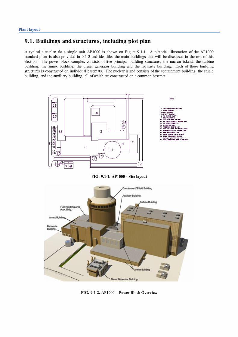
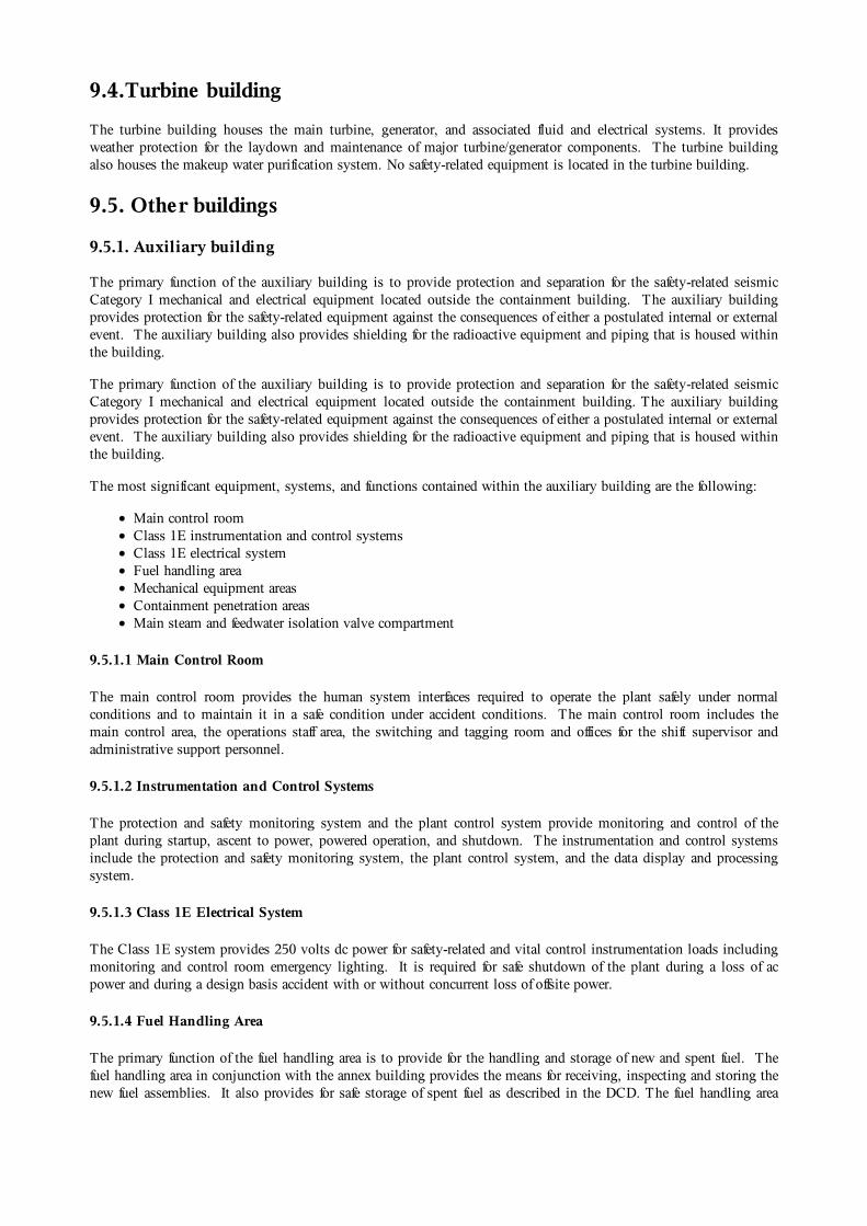
A typical site plan for a single unit AP1000 is shown on Figure 9.1-1. A pictorial illustration of the AP1000standard plant is also provided in 9.1-2 and identifies the main buildings that will be discussed in the rest of thisSection. The power block complex consists of five principal building structures; the nuclear island, the turbinebuilding, the annex building, the diesel generator building and the radwaste building. Each of these buildingstructures is constructed on individual basemats. The nuclear island consists of the containment building, the shieldbuilding, and the auxiliary building, all of which are constructed on a common basemat.
FIG. 9.1-1. AP1000 - Site layout
FIG. 9.1-2. AP1000 – Power Block Overview

9.1.1 Plant arrangement
The AP1000 containment contains a 16-foot (4.9 m) diameter main equipment hatch and a personnel airlock at theoperating deck level, and a 16-foot (4.9 m) diameter maintenance hatch and a personnel airlock at grade level. Theselarge hatches significantly enhance accessibility to the containment during outages and, consequently, reduce thepotential for congestion at the containment entrances. These containment hatches, located at the two different levels,allow activities occurring above the operating deck to be unaffected by activities occurring below the operating deck.
The containment arrangement provides significantly larger laydown areas than most conventional plants at both theoperating deck level and the maintenance floor level. Additionally, the auxiliary building and the adjacent annexbuilding provide large staging and laydown areas immediately outside of both large equipment hatches.
9.2. Reactor building
The reactor building of the AP1000 is a shield building surrounding the containment (Section 9.3).
9.3. Containment
9.3.1 Containment building
The containment building is the containment vessel and all structures contained within the containment vessel. Thecontainment building is an integral part of the overall containment system with the functions of containing the releaseof airborne radioactivity following postulated design basis accidents and providing shielding for the reactor core andthe reactor coolant system during normal operations.
The containment vessel is an integral part of the passive containment cooling system. The containment vessel andthe passive containment cooling system are designed to remove sufficient energy from the containment to prevent thecontainment from exceeding its design pressure following postulated design basis accidents.
The principal systems located within the containment building are the reactor coolant system, the passive corecooling system, and the reactor coolant purification portion of the chemical and volume control system.
9.3.2 S hield building
The shield building is the structure and annulus area that surrounds the containment vessel. During normaloperations the shield building, in conjunction with the internal structures of the containment building, provides therequired shielding for the reactor coolant system and all the other radioactive systems and components housed in thecontainment. During accident conditions, the shield building provides the required shielding for radioactive airbornematerials that may be dispersed in the containment as well as radioactive particles in the water distributed throughoutthe containment.
The shield building is also an integral part of the passive containment cooling system. The passive containmentcooling system air baffle is located in the upper annulus area. The function of the passive containment coolingsystem air baffle is to provide a pathway for natural circulation of cooling air in the event that a design basis accidentresults in a large release of energy into the containment. In this event the outer surface of the containment vesseltransfers heat to the air between the baffle and the containment shell. This heated and thus, lower density air flows upthrough the air baffle to the air diffuser and cooler and higher density air is drawn into the shield building through theair inlet in the upper part of the shield building.
Another function of the shield building is to protect the containment vessel from external events. The shieldbuilding protects the containment vessel and the reactor coolant system from the effects of tornadoes and tornadoproduced missiles. The shield building is also designed to prevent penetration of a large commercial aircraft intocontainment.
9.4.Turbine building
The turbine building houses the main turbine, generator, and associated fluid and electrical systems. It providesweather protection for the laydown and maintenance of major turbine/generator components. The turbine buildingalso houses the makeup water purification system. No safety-related equipment is located in the turbine building.
9.5. Other buildings
9.5.1. Auxiliary building
The primary function of the auxiliary building is to provide protection and separation for the safety-related seismicCategory I mechanical and electrical equipment located outside the containment building. The auxiliary buildingprovides protection for the safety-related equipment against the consequences of either a postulated internal or externalevent. The auxiliary building also provides shielding for the radioactive equipment and piping that is housed withinthe building.
The primary function of the auxiliary building is to provide protection and separation for the safety-related seismicCategory I mechanical and electrical equipment located outside the containment building. The auxiliary buildingprovides protection for the safety-related equipment against the consequences of either a postulated internal or externalevent. The auxiliary building also provides shielding for the radioactive equipment and piping that is housed withinthe building.
The most significant equipment, systems, and functions contained within the auxiliary building are the following:
Main control roomClass 1E instrumentation and control systemsClass 1E electrical systemFuel handling areaMechanical equipment areasContainment penetration areasMain steam and feedwater isolation valve compartment
9.5.1.1 Main Control Room
The main control room provides the human system interfaces required to operate the plant safely under normalconditions and to maintain it in a safe condition under accident conditions. The main control room includes themain control area, the operations staff area, the switching and tagging room and offices for the shift supervisor andadministrative support personnel.
9.5.1.2 Instrumentation and Control Systems
The protection and safety monitoring system and the plant control system provide monitoring and control of theplant during startup, ascent to power, powered operation, and shutdown. The instrumentation and control systemsinclude the protection and safety monitoring system, the plant control system, and the data display and processingsystem.
9.5.1.3 Class 1E Electrical System
The Class 1E system provides 250 volts dc power for safety-related and vital control instrumentation loads includingmonitoring and control room emergency lighting. It is required for safe shutdown of the plant during a loss of acpower and during a design basis accident with or without concurrent loss of offsite power.
9.5.1.4 Fuel Handling Area
The primary function of the fuel handling area is to provide for the handling and storage of new and spent fuel. Thefuel handling area in conjunction with the annex building provides the means for receiving, inspecting and storing thenew fuel assemblies. It also provides for safe storage of spent fuel as described in the DCD. The fuel handling area
provides for transferring new fuel assemblies from the new fuel storage area to the containment building and fortransferring spent fuel assemblies from the containment building to the spent fuel storage pit within the auxiliarybuilding.
The fuel handling area provides for removing the spent fuel assemblies from the spent fuel storage pit and loading theassemblies into a shipping cask for transfer from the facility. This area is protected from external events such astornadoes and tornado produced missiles. Protection is provided for the spent fuel assemblies, the new fuelassemblies and the associated radioactive systems from external events. The fuel handling area is constructed so thatthe release of airborne radiation following any postulated design basis accident that could result in damage to the fuelassemblies or associated radioactive systems does not result in unacceptable site boundary radiation levels.
9.5.1.5 Mechanical Equipment Areas
The mechanical equipment located in radiological control areas of the auxiliary building comprises the normalresidual heat removal pumps and heat exchangers, the spent fuel cooling system pumps and heat exchangers, thesolid, liquid, and gaseous radwaste pumps, tanks, demineralizers and filters, the chemical and volume controlpumps, and the heating, ventilating and air conditioning exhaust fans.
The mechanical equipment located in the clean areas of the auxiliary building consist of the heating, ventilating andair conditioning air handling units, associated equipment that service the main control room, instrumentation andcontrol cabinet rooms, the battery rooms, the passive containment cooling system recirculation pumps and heatingunit and the equipment associated with the air cooled chillers that are an integral part of the chilled water system.
9.5.1.6. Containment Penetration Areas
The auxiliary building contains all of the containment penetration areas for mechanical, electrical, andinstrumentation and control penetrations. The auxiliary building provides separation of the radioactive pipingpenetration areas from the non-radioactive penetration areas and separation of the electrical and instrumentation andcontrol penetration areas from the mechanical penetration areas. Also provided is separation of redundant divisions ofinstrumentation and control and electrical equipment.
9.5.1.7 Main steam and feedwater isolation valve compartments
The main steam and feedwater isolation valve compartments are contained within the auxiliary building. Thesecompartments are separated and each compartment contains:
One main steam line with its associated steam relief valves, steam generator power-operated relief valve, andmain steam isolation valveOne main feed line with its associated feed water control valve and main feed isolation valveOne start-up feed water line with its associated start-up feed water control valve and isolation valve
The auxiliary building provides an adequate venting area from the main steam and feedwater isolation valvecompartments in the event of a postulated leak in either a main steam line or feedwater line.
9.5.2. Annex building
The Annex building provides the main personnel entrance to the power generation complex. It includes access waysfor personnel and equipment to the clean areas of the nuclear island in the auxiliary building and to the radiologicalcontrol area. The building includes the health physics facilities for the control of entry to and exit from theradiological control area as well as personnel support facilities such as locker rooms. The building also contains thenon-1E ac and dc electric power systems, the ancillary diesel generators and their fuel supply, other electricalequipment, the technical support center, and various heating, ventilating and air conditioning systems. No safety-related equipment is located in the annex building.
The annex building includes the health physics facilities and provides personnel and equipment access ways to andfrom the containment building and the rest of the radiological control area via the auxiliary building. Provided arelarge, direct access ways to the upper and lower equipment hatches of the containment building for personnel accessduring outages and for large equipment entry and exit. The building includes a hot machine shop for servicing

radiological control area equipment. The hot machine shop includes decontamination facilities including a portabledecontamination system that may be used for decontamination operations throughout the nuclear island.
9.5.3.Diesel generator building
The diesel generator building houses two identical slide-along diesel generators separated by a three-hour fire wall. These generators provide backup power for plant operation in the event of disruption of normal power sources. Nosafety-related equipment is located in the diesel generator building.
9.5.4. Radwaste building
The radwaste building includes facilities for segregated storage of various categories of waste prior to processing, forprocessing by mobile systems, and for storing processed waste in shipping and disposal containers. No safety-relatedequipment is located in the radwaste building. Dedicated floor areas and trailer parking space for mobile processingsystems is provided for the following:
Contaminated laundry shipping for offsite processingDry waste processing and packagingHazardous/mixed waste shipping for offsite processingChemical waste treatmentEmpty waste container receiving and storageStorage and loading packaged wastes for shipment.Monitor Tanks.
The radwaste building also provides for temporary storage of other categories of plant wastes.
Plant performance
The AP1000 is a logical extension of the AP600 design. The AP1000 maintains the same design philosophy ofAP600, such as use of proven components, systems simplification and state-of-the-art construction techniques. TheAP1000 optimizes the power output while maintaining the AP600 NI footprint, to reduce capital and generationcosts.
10.1 Simplification
AP1000 is an advanced passive plant that has been designed to meet globally recognized requirements. A concertedeffort has been made to simplify systems and components, to facilitate construction, operation and maintenance and toreduce the capital and generating costs.
The use of passive systems allows the plant design to be significantly simpler. In addition, the passive safetysystems do not require the large network of safety support systems found in current generation nuclear power plants(e.g., Class 1E ac power, safety HVAC, safety cooling water systems and associated seismic buildings). The AP1000uses 50% fewer valves, 83% less pipe (safety grade), 87% less cable, 36% fewer pumps, and 56% less seismicbuilding volumes than current Westinghouse plants.
Simplicity reduces the cost for reasons other than reduction of the number of items to be purchased. With a fewernumber of components, installation costs are reduced, construction time is shortened and maintenance activities areminimized.
10.2 Construction Schedule
The AP1000 has been designed to make use of modern modular construction techniques. Not only does the designincorporate vendor designed skids and equipment packages, it also includes large structural modules and special

equipment modules. Modularization allows construction tasks that were traditionally performed in sequence to becompleted in parallel. The modules, constructed in factories, can be assembled at the site for a planned constructionschedule, as predicted by Westinghouse, of 3 years – from ground-breaking to fuel load. This duration has beenverified by experienced construction managers through 4D (3D models plus time) reviews of the constructionsequence.
10.3 Availability and O&M Costs
The AP1000 combines proven Westinghouse PWR technology with utility operating experience to enhancereliability and operability. Steam generators are similar to the recent replacement steam generators, and canned motorpumps and rugged turbine generators are proven performers with outstanding operating records. The digital on-linediagnostic instrumentation and control system features an integrated control system that avoids reactor trips due tosingle channel failure. In addition, the plant design provides large margins for plant operation before reaching thesafety limits. This assures a stable and reliable plant operation with a reduced number of reactor trips (less than oneper year). Based on the above, and considering the short planned refuelling outage (17 days) and an 18-month fuelcycle the AP1000 has been estimated to exceed the 93% availability goal.
For AP1000 availability is enhanced by the simplicity designed into the plant, as described above. There are fewercomponents which result in lower maintenance costs, both planned and unplanned. In addition, the great reduction insafety-related components results in a large reduction in inspection and tests. Simplicity is also reflected in thereduced AP1000 staffing requirements.
Deployment status and planned schedule
12.1. United States:
The AP1000 is based extensively on the AP600 passive plant design that received Final Design Approval andDesign Certification from the United States Nuclear Regulatory Commission (U.S. NRC) in September 1998 andDecember 1999, respectively. Westinghouse and the U.S. NRC conducted a 12-month pre-licensing review of theAP1000 that established the applicability of AP600 tests and selected safety analysis computer codes to the AP1000design certification application. On March 28, 2002, following the pre-application review, Westinghouse submittedan Application for Final Design Approval and Design Certification for the AP1000. The U.S. NRC completed itsReview for Acceptance and docketed the Application on June 25, 2002. The docketing of the application signifiesthat its content is acceptable for review by the U.S. NRC as a complete safety case, in accordance with appropriateU.S. regulations. The U.S. NRC issued their Draft Safety Evaluation Report for AP1000 on June 16, 2003. TheU.S. NRC completed the review of the AP1000 and issued a Final Design Approval (FDA) in 2004.
The U.S. regulatory process (per Title 10 of the Codes of Federal Regulations, Part 52, or 10CFR52) forconstruction and operation of new plants is illustrated in Figure 11.1-1. Under this process, a plant design that hasreceived Design Certification is referenced by an applicant in applying for a Combined Construction Permit andOperating Licence (COL).
In 2007, in view of the large number of AP1000 units under contract or being planned in the United States,Westinghouse submitted for NRC review and approval an amended application for AP1000 Design Certification(Docketed by NRC – January 2008). This amended Design Certification Document (DCD) application includesaddressing/closing nearly 40% of the 166 COL Information Items (those that are design-related). DCD Rev 17 wassubmitted to NRC in September 2008, with final rulemaking expected for 2011, to support deployment of the firstwave of AP1000 units in the U.S.

Figure 11.1-1 U.S. NRC Regulatory Process under 10CFR52
Applications for 12 AP1000 COLs have been docketed by the U.S. NRC, as summarized in the following table:
In 2008 EPC (Engineering, Procurement, Construction) contracts were signed for 4 AP1000 Units: two units inSouth Carolina at V.C. Summer (Utility: SCE&G / SCANA) and two units in Georgia at Vogtle (Utility: SouthernCompany). An additional EPC contract for 2 AP1000 units signed in early 2009 for Shearon Harris (Utility:Progress Energy). Site preparation work and procurement of the large, long-lead nuclear steam supply systemcomponents has been initiated at both the V.C. Summer and Vogtle sites during 2009, with planned first concrete forthe first unit at each site in the second half of 2011 (following COL approval from the U.S. NRC). Projectedcommercial operation date for the two units at V.C. Summer is 2016 and 2018, respectively, and for the two units atVogtle is 2016 and 2017, respectively.
12.2. China
Contracts for the first 4 AP1000 units in China were signed in July 2007, for two units at Sanmen (First unit beginsoperation in 2013) and for two units at Haiyang (Fourth unit begins operation in 2015).
The plant owners have submitted the Preliminary Safety Analysis Report (PSAR) to the Chinese Regulator (NNSA– National Nuclear Safety Administration) in 2008. Following its review, NNSA has issue construction permits for
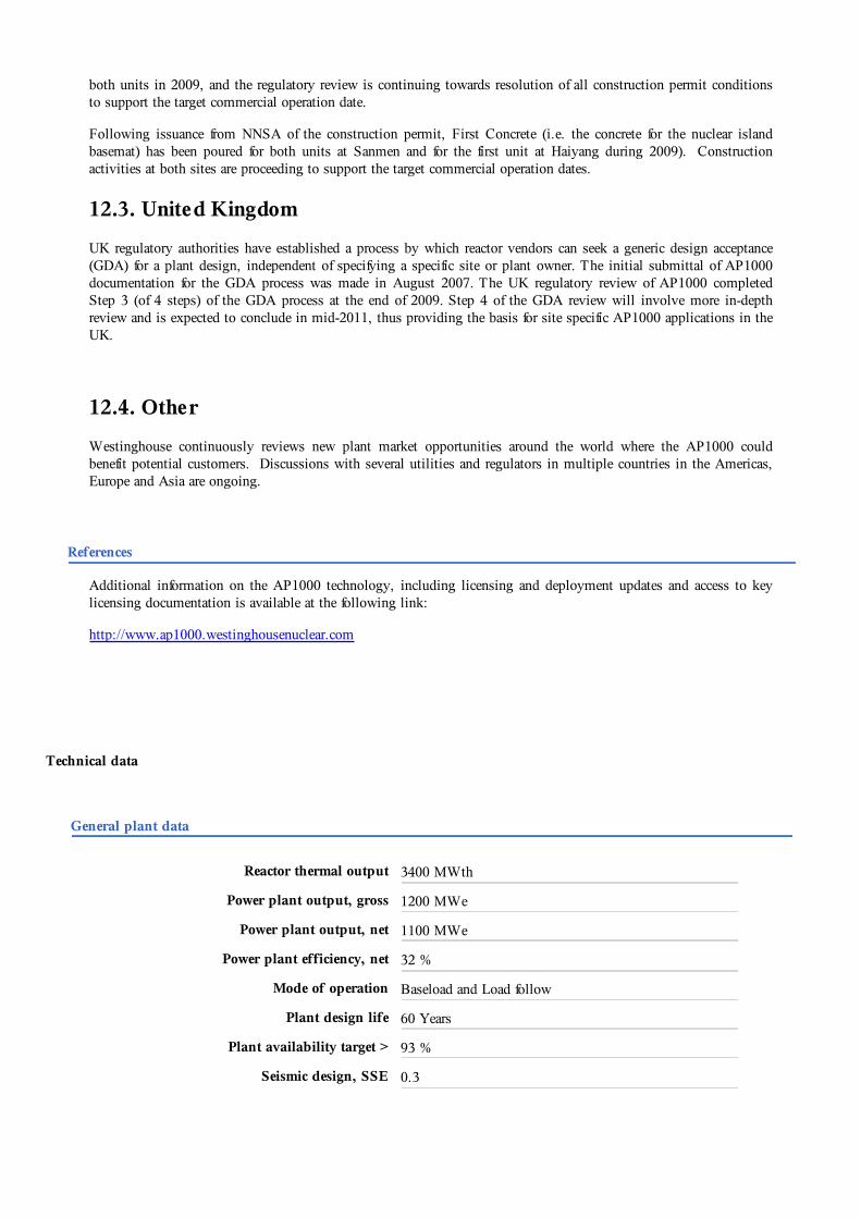
both units in 2009, and the regulatory review is continuing towards resolution of all construction permit conditionsto support the target commercial operation date.
Following issuance from NNSA of the construction permit, First Concrete (i.e. the concrete for the nuclear islandbasemat) has been poured for both units at Sanmen and for the first unit at Haiyang during 2009). Constructionactivities at both sites are proceeding to support the target commercial operation dates.
12.3. United Kingdom
UK regulatory authorities have established a process by which reactor vendors can seek a generic design acceptance(GDA) for a plant design, independent of specifying a specific site or plant owner. The initial submittal of AP1000documentation for the GDA process was made in August 2007. The UK regulatory review of AP1000 completedStep 3 (of 4 steps) of the GDA process at the end of 2009. Step 4 of the GDA review will involve more in-depthreview and is expected to conclude in mid-2011, thus providing the basis for site specific AP1000 applications in theUK.
12.4. Other
Westinghouse continuously reviews new plant market opportunities around the world where the AP1000 couldbenefit potential customers. Discussions with several utilities and regulators in multiple countries in the Americas,Europe and Asia are ongoing.
References
Additional information on the AP1000 technology, including licensing and deployment updates and access to keylicensing documentation is available at the following link:
http://www.ap1000.westinghousenuclear.com
Technical data
General plant data
Reactor thermal output 3400 MWth
Power plant output, gross 1200 MWe
Power plant output, net 1100 MWe
Power plant efficiency, net 32 %
Mode of operation Baseload and Load follow
Plant design life 60 Years
Plant availability target > 93 %
Seismic design, SSE 0.3
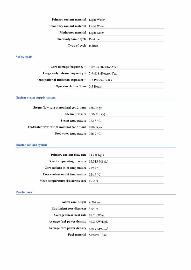
Primary coolant material Light Water
Secondary coolant material Light Water
Moderator material Light water
Thermodynamic cycle Rankine
Type of cycle Indirect
Safety goals
Core damage frequency < 5.09E-7 /Reactor-Year
Large early release frequency < 5.94E-8 /Reactor-Year
Occupational radiation exposure < 0.7 Person-Sv/RY
Operator Action Time 0.5 Hours
Nuclear steam supply system
Steam flow rate at nominal conditions 1889 Kg/s
Steam pressure 5.76 MPa(a)
Steam temperature 272.8 °C
Feedwater flow rate at nominal conditions 1889 Kg/s
Feedwater temperature 226.7 °C
Reactor coolant system
Primary coolant flow rate 14300 Kg/s
Reactor operating pressure 15.513 MPa(a)
Core coolant inlet temperature 279.4 °C
Core coolant outlet temperature 324.7 °C
Mean temperature rise across core 45.2 °C
Reactor core
Active core height 4.267 m
Equivalent core diameter 3.04 m
Average linear heat rate 18.7 KW/m
Average fuel power density 40.2 KW/KgU
Average core power density 109.7 MW/m3
Fuel material Sintered UO2

Cladding material ZIRLO™
Outer diameter of fuel rods 9.5 mm
Rod array of a fuel assembly Square , 17x17,XL
Number of fuel assemblies 157
Enrichment of reload fuel at equilibrium core 4.8 Weight %
Fuel cycle length 18 Months
Average discharge burnup of fuel 60000 MWd/Kg
Control rod absorber material Ag-In-Cd(Black), Ag-In-Cd /304SS(Gray)
Soluble neutron absorber H3BO3
Reactor pressure vessel
Inner diameter of cylindrical shell 4038.6 mm
Wall thickness of cylindrical shell 203 mm
Design pressure 17.2 MPa(a)
Design temperature 343.3 °C
Base material Carbon Steel
Total height, inside 12056 mm
Steam generator or Heat Exchanger
Type Delta-125, U-Tube,Vertical
Number 2
Total tube outside surface area 11477 m2
Number of heat exchanger tubes 10025
Tube outside diameter 17.5 mm
Tube material Inconel 690-TT
Transport weight 663.7 t
Reactor coolant pump (Primary circulation System)
Number of pumps 4
Pump speed 1800 rpm
Head at rated conditions 111.3 m
Flow at rated conditions 4.97 m3/s
Pressurizer

Total volume 59.47 m3
Steam volume (Working medium volume ): fullpower/zero power
31.14 m3
Heating power of heater rods 1600 kW
Primary containment
Overall form (spherical/cylindrical) Cylindrical
Dimensions - diameter 39.6 m
Dimensions - height 82.3 m
Design pressure 0.5067 MPa
Design temperature 148.9 °C
Design leakage rate 0.10 Volume % /day
Residual heat removal systems
Active/passive systems Passive
Safety injection systems
Active/passive systems Passive
Turbine
Number of turbine sections per unit (e.g.HP/MP/LP)
1 HP / 3 LP
Turbine speed 1800 rpm
Generator
Rated power 1375 MVA
Active power 1237 MW
Voltage 24 kV
Frequency 60 Hz
Condenser
Type Multipressure (cooling towers) or Single pressure (directcooling)
Condenser pressure 9.1 kPa

Plant configuration and layout
Plant configuration options Ground-based
Feedwater pumps
Type Motor Driven
Number 3