clean agent fire extinguishing · pdf fileclean agent fire extinguishing system mx 200...
TRANSCRIPT

Page 1 of 6
CLEAN AGENT FIRE EXTINGUISHING SYSTEMMX 200 Extinguishing Agent Cylinders
The technical data described herein is for components of the Minimax Fire Products MX 200 Clean Agent System. For design, installation, and operation instructions, refer to the latest edition of the original source documents: Installation and Service Manual (Part No. 889331), Design Manual (Part No. 889336), and Operation Manual (Part No. 889329).
Minimax Fire Products Technical Services: (480) 553-5670 Email: [email protected]
TECHN
ICAL D
ATA
Form No. F_011314 16.04.14 Rev 16.1
1. DESCRIPTIONThe Minimax Fire Products MX 200 Fire Extinguishing System uses HFC-227ea extinguishing agent that is stored in the system’s extinguishing agent container(s) until system activation. The container assembly includes a welded or seamless steel cylinder filled with HFC-227ea fluid, assembled with the following components:
• Cylinder valve with burst disc, pressure gauge, protective neck ring, protective cylinder cap and valve cap.
• Five cylinder sizes are available for 360 psi (25 bar): 55, 130, 270, 370, and 450 lbs. (22, 52, 106, 147, and 180 l).
• Three cylinder sizes are available for 725 psi (50 bar): 200, 350, and 450 lbs (80, 140, and 180 l)• Cylinders are designed, manufactured, and labeled in accordance with the US Dept. of
Transportation Standard DOT 4BW-500, DOT 3AA-910, and TC (Transportation Canada - 360 psi (25 bar) systems only).
• Cylinders can only be installed in the upright position. • To create the pressure necessary for the agent to be released, the extinguishing agent container is superpressurized with
nitrogen at a pressure of 360 psi (25 bar) or 725 psi (50 bar). • Cylinder fill density is dependent on the area of protection size. Agent concentration varies due to the expected class of fire
(A, B, or C).Each cylinder is equipped with a special high-speed opening cylinder valve:
• Operates according to the differential pressure principle and has a piston and a brass housing. • Includes a burst disc to protect from excessive pressure.• Includes a pressure gauge for indication of the filling pressure.• The valve is appropriate for high discharge rates and makes the extinguishant discharge possible within 10 seconds.• Available in the nominal sizes 1-1/2 inch for the 55 and 130 lb. cylinders, and 2 inch for 200, 270, 350, 370, and 450 lb.
cylinders. An optional manual release assembly with pneumatic discharge pressure switch can be ordered separately for installation in the piping:
• The pneumatic discharge pressure switch is required with manual release installation per NFPA 2001.• The status of the pressure switch can be monitored by the fire agent release control panel.
A cylinder nameplate label is attached to the extinguishing agent container:• Contains maintenance and filling information, as well as information about the filling quantity. • A UL Listing label and FM Approval label are also attached to the cylinder.
Protective caps are used to protect sensitive components (e.g. valves) of the extinguishing agent containers:• Protects the valves from damage during transport.
NOTE: The protective valve caps must be attached before each transport.An installation clamp is required to be ordered with each container assembly (available separately):
• The cylinder must be attached to a wall using the designated installation clamp.
NOTE: System detection is controlled by an approved system release control panel with compatible detection.
2. LISTINGS AND APPROVALSUL Listed: Clean Agent Extinguishing System UnitFM Approved: Clean Agent Fire Extinguishing System
Minimax Technical Data may be found on Minimax Fire Products’ Web site at
http://www.minimaxfp.com/.The Web site may include a more recent
edition of this Technical Data Page.
Replaces Form No. F_011314 Rev 14.1(Replaced part no.s 91 4154, 91 4155, & 889320 in Table 1)
Form No. F_011314 16.05.19 Rev 16.1
Page 2 of 6
CLEAN AGENT FIRE EXTINGUISHING SYSTEMMX 200 Extinguishing Agent Cylinders
Minimax Fire Products Technical Services: (480) 553-5670 Email: [email protected]
TECHN
ICAL D
ATA
3. TEChNICAL DATA• Minimum and Maximum Agent Storage Temperatures: 0 °F to 122 °F (-18 °C to 50 °C) • Minimum and Maximum Temperatures of Protected Spaces per UL and FM: 60 °F to 80 °F (15.6 °C to 26.7 °C)Cylinder Specifications• Fill Density: Min. 31.2 lb/ft3 (500 kg/m3), Max. 71.1 lb/ft3 (1140 kg/m3) at 69.8 °F (21 °C)NOTE: The accurate filling quantity depends on the necessary extinguishant quantity and the layout of the piping.Valve Specifications• Working Pressure: 360 psi (25 bar) or 725 psi (50 bar) at 70 °F (21 °C) • Max. Working Pressure: 508 psi (35 bar) or 870 psi (60 bar) at 122 °F (50 °C)• Response Pressure at Bursting Disc for 360 psi (25 bar) System: 900 psi (62 bar ) at 68 °F (20 °C)• Response Pressure at Bursting Disc for 725 psi (50 bar) System: 1276 psi (88 bar) for 2” valves, 1291 psi (89 bar) for 1-1/2”
valves at 68 °F (20 °C)Gauge Specifications• Agent: HFC-227ea• 360 psi (25 bar) system:
• Maximum Pressure: 725 psi (50 bar)• Indicating Range: 0 to 508 psi (35 bar)
• 725 psi (50 bar) system:• Maximum Pressure: 1160 psi (80 bar)• Indicating Range: 0 to 870 psi (60 bar)
• Gauge Nominal Size: 2” (50 mm)• Accuracy Class: 1.6Material StandardsCylinder: Welded Steel, Powder Coated Red, DOT Standard 4BW-500 or Seamless Steel, Powder Coated Red, DOT Standard
3AA-910/TPEDProtective Neck Ring: AISI 1015 Hot Rolled Steel, Powder Coated BlackCylinder Valve:
• Housing, Adapter, Screws: Brass• Seal Retainer: Brass• O-ring/Seal of Seat: NBR• Bursting Disk: Nickel• Spring: Steel
Gauge: AluminumLiquid Level Indicator
• Stem: Brass• O-Ring: Buna N• Float: Ceramic• Protective Cap: PVC• Tape: Painted Steel
Protective Cylinder Cap: AISI 1026, Hot Rolled Steel, Powder Coated BlackInstallation Clamp: SteelOrdering InformationThe cylinders are filled according to the ordering designations. Extinguishant cylinders are completely assembled and filled. For a complete Single Container System, the following must be ordered separately: release devices, optional manual release assembly with pneumatic discharge pressure switch, discharge nozzles, hose or NPT connections, installation clamp, and warning signs. An approved release control panel with compatible detection system is also required.
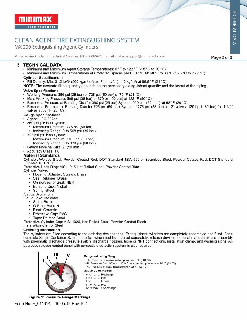
Figure 1: Pressure Gauge Markings
Gauge Indicating Range: I. Pressure at minimum temperature 0 °F (-18 °C)II-III. Pressure from 90% to 110% from charging pressure at 70 °F (21 °C) IV. Pressure at max. temperature 122 °F (50 °C)Gauge Color Marked:
0 to I...........RechargeI to II...........RedII to III.........GreenIII to IV........RedIV to max....Overcharge

Page 3 of 6
CLEAN AGENT FIRE EXTINGUISHING SYSTEMMX 200 Extinguishing Agent Cylinders
Minimax Fire Products Technical Services: (480) 553-5670 Email: [email protected]
TECHN
ICAL D
ATA
Form No. F_011314 16.04.14 Rev 16.1
Figure 2
TABLE 1: MX Fire Extinguishing System Components
Item No. Description Part No.
1
Pressure Gauge360psi (25 bar) 91 2100725psi (50 bar) 91 2102
Contact Pressure Gauge / Low pressure Switch (Optional)
360psi (25 bar) NO 88 9306
725psi (50 bar) NO 88 9309
2 Hose1-1/2” 90º Bend 91 20752” 90º Bend 91 2076
3 Swivel Adaptor1-1/2” NPT 175622” NPT 17563
4 Check Valve 2” 91 20715 Electric Release Device 88 93236 Pneumatic Release Device 88 76697 Pneumatic/Manual Release Device 88 76708 Manual Release Device 88 7668
9 Pilot Hose24” 88 783439” 88 783559” 88 7836
10 Pilot Hose Adaptor 88 764411 Pressure Malfunction Safety Assembly 1601012 Screw Reset Tool 17096
13Clamp for Extinguishing Agent Cylinder
60lb / 140lb 19368280lb / 390lb / 220lb / 500lb 88 7639
14 Hex. Nut DIN934-M12-B-GAL ZN/B 81 138615 Washer DIN125-B13ST GAL ZN/B 10 988616 Protection Cap17 Ring-Protection Cap18 Extinguishing Agent Cylinder19 Siphon Tube
1
23
4
5
67 8
910
12
13
19
11
1415
16
17
18

Form No. F_011314 16.05.19 Rev 16.1
Page 4 of 6
CLEAN AGENT FIRE EXTINGUISHING SYSTEMMX 200 Extinguishing Agent Cylinders
Minimax Fire Products Technical Services: (480) 553-5670 Email: [email protected]
TECHN
ICAL D
ATA
Figure 3
TABLE 2: MX 200 Cylinder Part Numbers and Dimensions12
PRESSURE AT 70º F (20º C)
Nominal Volume
Part No. Valve Type
A / A25
A(in.)
B(in.)
C(in.)
D(in.)
E(in.)
Amount Filled Empty WeightMin. Max.
360 PSI(25 bar)
55 lb 91 4146 40.8 23.2 15.8 10 4.75 25 lbs 55 lbs 88 lbs130 lb 88 9098 65.4 47.8 27.5 10 4.75 58 lbs 130 lbs 108 lbs270 lb 88 9100 61.4 40.9 27.5 16 6 117 lbs 266 lbs 190 lbs370 lb 88 9103 74.5 54.0 41.1 16 6 163 lbs 369 lbs 229 lbs450 lb 91 0508 86.0 65.5 51.2 16 6 199 lbs 452 lbs 313 lbs
725 PSI(50 bar)
200 lb 88 8571 55.4 34.9 23.6 16 6 89 lbs 185 lbs 218 lbs350 lb 88 8574 74.3 53.8 41.4 16 6 155 lbs 324 lbs 289 lbs450 lb 88 8576 88.0 67.5 51.2 16 6 199 lbs 416 lbs 395 lbs
With Liquid Level Indicator
360 PSI(25 bar)
270 lb 91 4148 61.4 40.9 27.5 16 6 116 lbs 266 lbs 210 lbs370 lb 91 4149 74.5 54.0 41.4 16 6 162 lbs 369 lbs 251 lbs450 lb 91 4150 86.0 65.5 51.2 16 6 199 lbs 452 lbs 286 lbs
1 Extinguishing agent cylinder complete with valve, ciphon tube, ring and protection cap, without extinguishing agent.2 All dimensions are appoximate, variations due to manufacturing tolerances are possible.
Form No. F_011314 16.05.19 Rev 16.1
Page 5 of 6
CLEAN AGENT FIRE EXTINGUISHING SYSTEMMX 200 Extinguishing Agent Cylinders
Minimax Fire Products Technical Services: (480) 553-5670 Email: [email protected]
TECHN
ICAL D
ATA
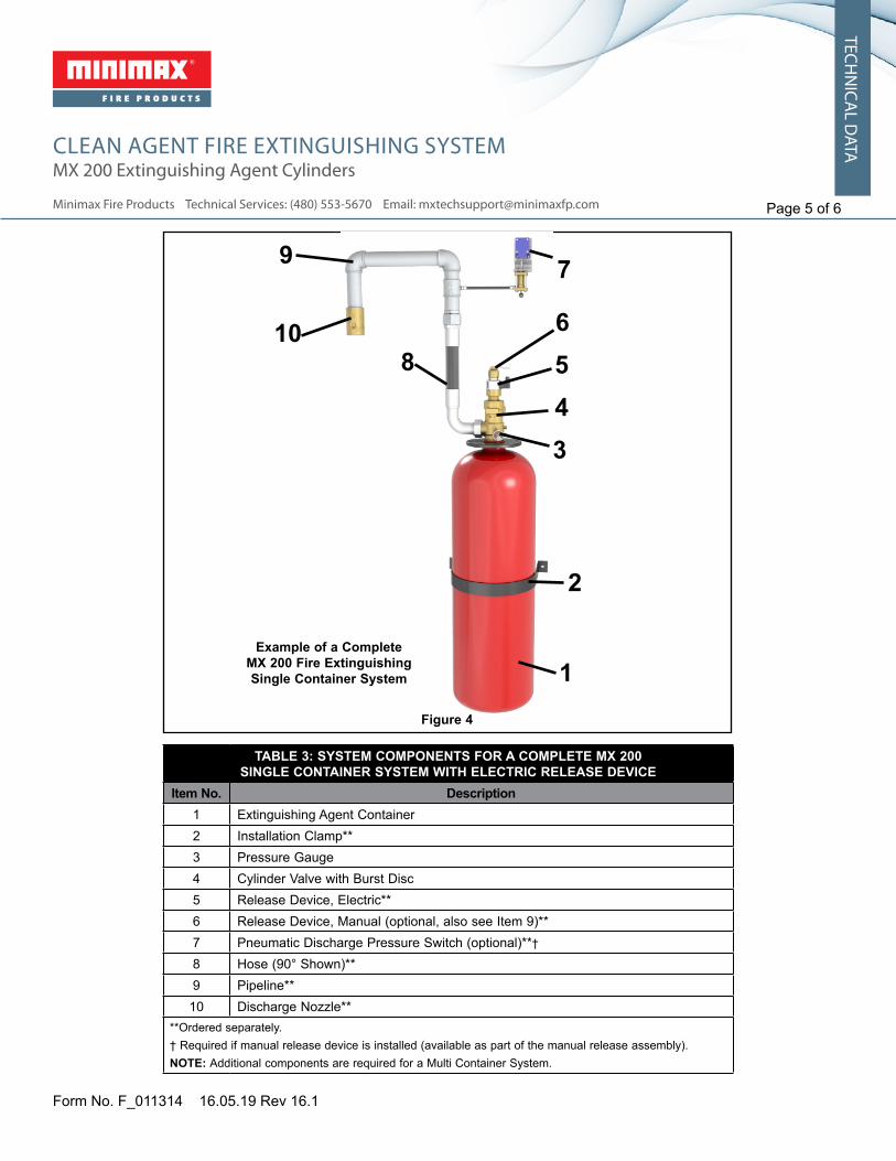
Example of a Complete MX 200 Fire Extinguishing Single Container System
Figure 4
TABLE 3: SYSTEM COMPONENTS FOR A COMPLETE MX 200
SINGLE CONTAINER SYSTEM WITh ELECTRIC RELEASE DEVICEItem No. Description
1 Extinguishing Agent Container2 Installation Clamp**3 Pressure Gauge4 Cylinder Valve with Burst Disc5 Release Device, Electric**6 Release Device, Manual (optional, also see Item 9)**7 Pneumatic Discharge Pressure Switch (optional)**†
8 Hose (90° Shown)**9 Pipeline**
10 Discharge Nozzle****Ordered separately.† Required if manual release device is installed (available as part of the manual release assembly).NOTE: Additional components are required for a Multi Container System.
1
2
3456
7
8
9
10

Page 6 of 6
CLEAN AGENT FIRE EXTINGUISHING SYSTEMMX 200 Extinguishing Agent Cylinders
Minimax Fire Products Technical Services: (480) 553-5670 Email: [email protected]
TECHN
ICAL D
ATA
Form No. F_011314 16.04.14 Rev 16.1
Figure 5: Example of a Complete MX 200 Fire Extinguishing Multi Container System
TABLE 4: ADDITIONAL SYSTEM COMPONENTS REQUIRED FOR A MX 200 MULTI CONTAINER SYSTEM***
Item No. Description1 Pneumatic Release Device2 Check Valve3 Pilot Line4 Pilot Line Adapter (one required for connecting each pilot line end and for connecting each pilot line safety valve)5 Pressure Malfunction Safety Assembly
***Components required in addition to the items indicated in Figure 3 for a Single Container System.
12
3 45
Replaces Form No. F_011314 Rev 14.1(Replaced part no.s 91 4154, 91 4155, & 889320 in Table 1)