ap2610-20_install 9034544-01_
TRANSCRIPT
5/9/2018 AP2610-20_Install 9034544-01_ - slidepdf.com
http://slidepdf.com/reader/full/ap2610-20install-9034544-01 1/2P/N: 9034544-01
Enterasys Wireless Controller, Access Points and Convergence Software Enterasys Wireless AP Installation Instructions
© 2011 Enterasys Networks, Inc.
Unpacking and mounting the Enterasys Wireless AP
This device is suitable for use in environmental air space in accordance withSection 300.22.C of the National Electrical Code, and Sections 2-128,12-010(3) and 12-100 of the Canadian Electrical Code, Part 1, C22.1.
Refer to the Enterasys Wireless Controller, Access Points and Convergence
Software User Guide, Appendix B, "Regulatory information," for completeregulatory information.
The Enterasys Wireless AP has two models:• AP2610: internal dual (multimode) diversity antennas• AP2620: dual external antennas, RP-SMA connectors
Unpack the Wireless AP from its carton. Also in the carton are:• 1 wall mounting bracket• 3 screws and 3 wall plugs• 1 plastic rivet (to secure Wireless AP to bracket)• For Model AP2620, the dual external antennas are also included.
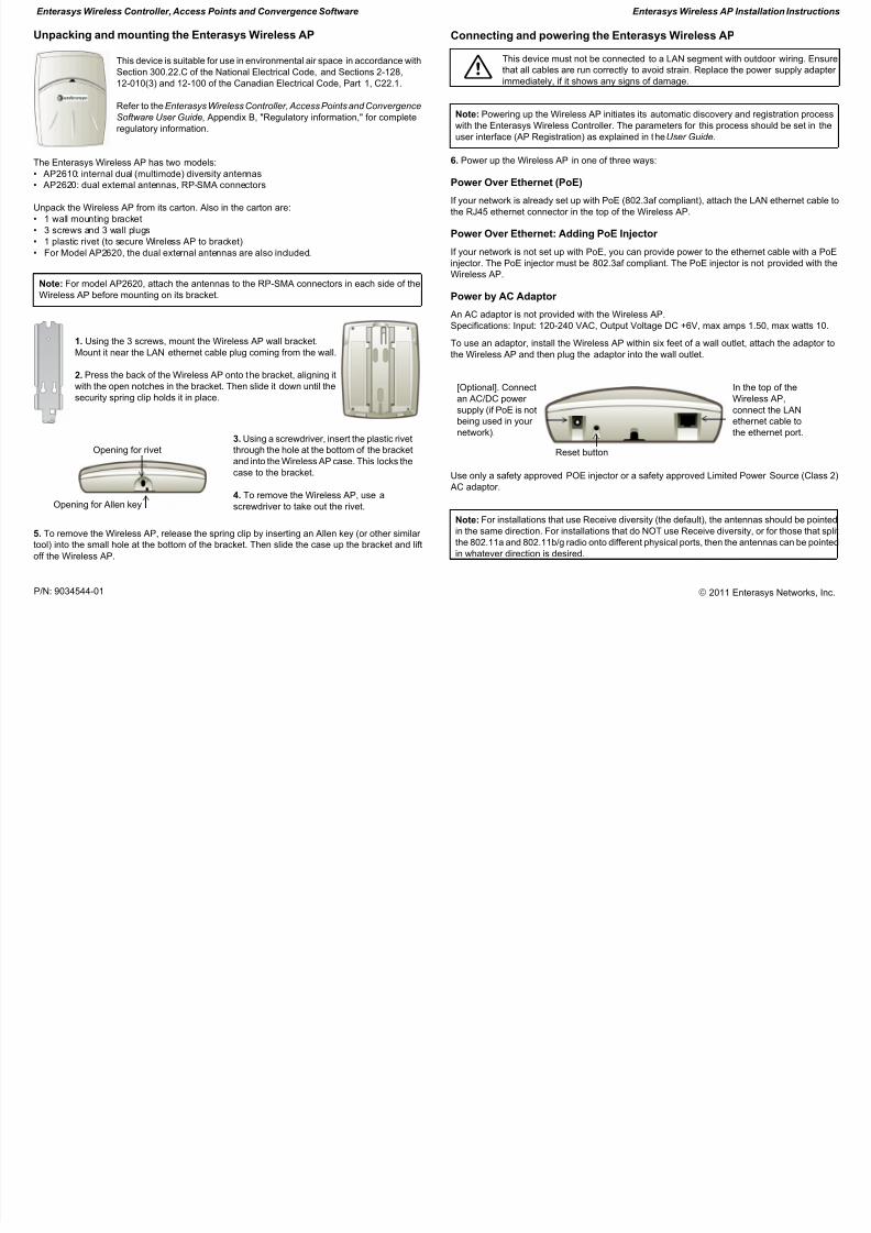
1. Using the 3 screws, mount the Wireless AP wall bracket.Mount it near the LAN ethernet cable plug coming from the wall.
2. Press the back of the Wireless AP onto the bracket, aligning itwith the open notches in the bracket. Then slide it down until thesecurity spring clip holds it in place.
5. To remove the Wireless AP, release the spring clip by inserting an Allen key (or other similar tool) into the small hole at the bottom of the bracket. Then slide the case up the bracket and liftoff the Wireless AP.
Connecting and powering the Enterasys Wireless AP
6. Power up the Wireless AP in one of three ways:
Power Over Ethernet (PoE)
If your network is already set up with PoE (802.3af compliant), attach the LAN ethernet cable tothe RJ45 ethernet connector in the top of the Wireless AP.
Power Over Ethernet: Adding PoE Injector
If your network is not set up with PoE, you can provide power to the ethernet cable with a PoEinjector. The PoE injector must be 802.3af compliant. The PoE injector is not provided with theWireless AP.
Power by AC Adaptor
An AC adaptor is not provided with the Wireless AP.Specifications: Input: 120-240 VAC, Output Voltage DC +6V, max amps 1.50, max watts 10.
To use an adaptor, install the Wireless AP within six feet of a wall outlet, attach the adaptor tothe Wireless AP and then plug the adaptor into the wall outlet.
Use only a safety approved POE injector or a safety approved Limited Power Source (Class 2)AC adaptor.
Note: For model AP2620, attach the antennas to the RP-SMA connectors in each side of theWireless AP before mounting on its bracket.
3. Using a screwdriver, insert the plastic rivetthrough the hole at the bottom of the bracketand into the Wireless AP case. This locks thecase to the bracket.
4. To remove the Wireless AP, use ascrewdriver to take out the rivet.
Opening for rivet
Opening for Allen key
7 This device must not be connected to a LAN segment with outdoor wiring. Ensurethat all cables are run correctly to avoid strain. Replace the power supply adapter immediately, if it shows any signs of damage.
Note: Powering up the Wireless AP initiates its automatic discovery and registration processwith the Enterasys Wireless Controller. The parameters for this process should be set in theuser interface (AP Registration) as explained in the User Guide.
[Optional]. Connectan AC/DC power supply (if PoE is notbeing used in your network).
In the top of theWireless AP,connect the LANethernet cable tothe ethernet port.
Note: For installations that use Receive diversity (the default), the antennas should be pointedin the same direction. For installations that do NOT use Receive diversity, or for those that splitthe 802.11a and 802.11b/g radio onto different physical ports, then the antennas can be pointedin whatever direction is desired.
Reset button
5/9/2018 AP2610-20_Install 9034544-01_ - slidepdf.com
http://slidepdf.com/reader/full/ap2610-20install-9034544-01 2/2P/N: 9034544-01
Enterasys Wireless Controller, Access Points and Convergence Software Enterasys Wireless AP Installation Instructions
© 2011 Enterasys Networks, Inc.
Auspacken und montieren des Enterasys Wireless AP
Dieses Gerät ist geeignet für die Nutzung in Luftschächten entsprechendAbsatz 300.22.C des US - National Electrical Code und den Absätzen 2-128,12-010(3) und 12-100 des Canadian Electrical Code, Part 1, C22.1.
Die gesamten Informationen zu den regulatorischen Vorschriften finden Sieunter: Enterasys Wireless Controller, Access Points and Convergence Software
User Guide, Appendix B, "Regulatory information".
Der Enterasys Wireless AP ist in zwei Modellen lieferbar:• AP2610: Interne Dualband (Multimode) Diversity-Antennen• AP2620: Externe Dualband-Antennen, RP-SMA-Stecker
Nehmen Sie den Wireless AP aus der Verpackung. In dem Verpackungskarton befinden sich auch:• eine Wandhalterung• 3 Schrauben und 3 Wanddübel• ein Plastikniet (zum Befestigen des Wireless AP an der Halterung)• Beim Modell AP2620 sind außerdem die externen Dualband-Antennen enthalten.
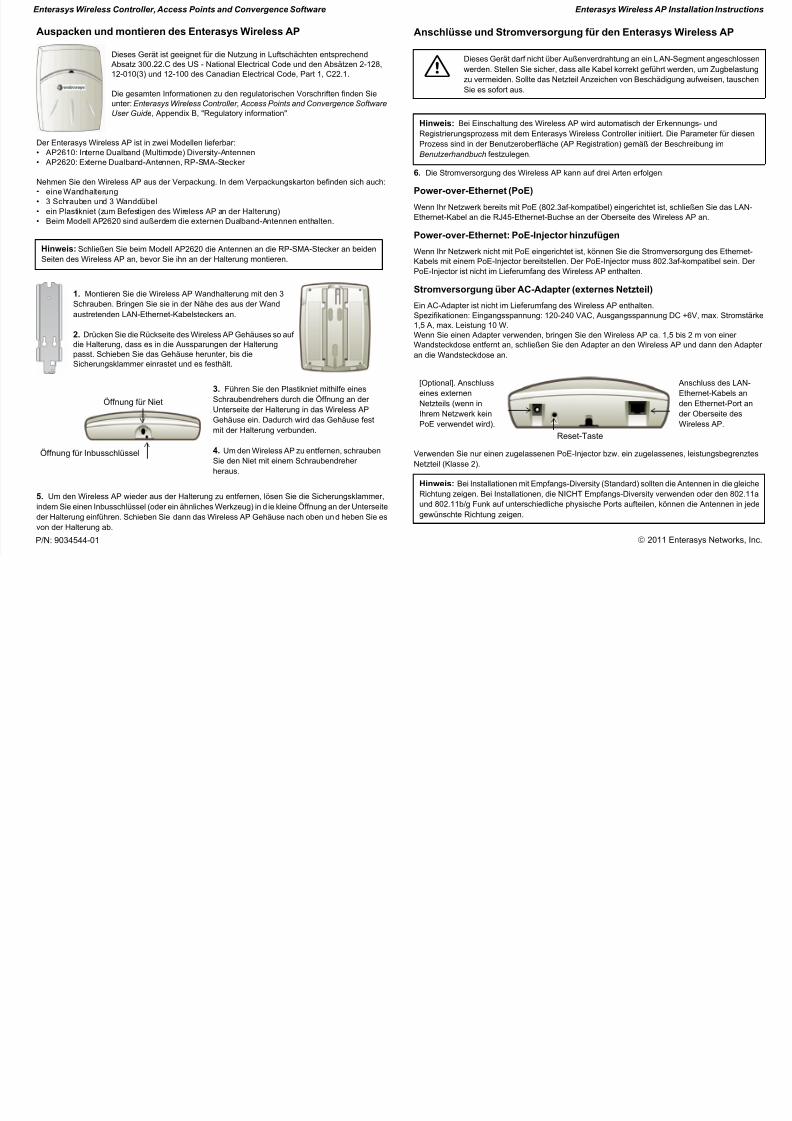
1. Montieren Sie die Wireless AP Wandhalterung mit den 3Schrauben. Bringen Sie sie in der Nähe des aus der Wandaustretenden LAN-Ethernet-Kabelsteckers an.
2. Drücken Sie die Rückseite des Wireless AP Gehäuses so auf die Halterung, dass es in die Aussparungen der Halterungpasst. Schieben Sie das Gehäuse herunter, bis dieSicherungsklammer einrastet und es festhält.
5. Um den Wireless AP wieder aus der Halterung zu entfernen, lösen Sie die Sicherungsklammer,indem Sie einen Inbusschlüssel (oder ein ähnl iches Werkzeug) in die kleine Öffnung an der Unterseiteder Halterung einführen. Schieben Sie dann das Wireless AP Gehäuse nach oben und heben Sie esvon der Halterung ab.
Anschlüsse und Stromversorgung für den Enterasys Wireless AP
6. Die Stromversorgung des Wireless AP kann auf drei Arten erfolgen:
Power-over-Ethernet (PoE)
Wenn Ihr Netzwerk bereits mit PoE (802.3af-kompatibel) eingerichtet ist, schließen Sie das LAN-Ethernet-Kabel an die RJ45-Ethernet-Buchse an der Oberseite des Wireless AP an.
Power-over-Ethernet: PoE-Injector hinzufügen
Wenn Ihr Netzwerk nicht mit PoE eingerichtet ist, können Sie die Stromversorgung des Ethernet-Kabels mit einem PoE-Injector bereitstellen. Der PoE-Injector muss 802.3af-kompatibel sein. Der PoE-Injector ist nicht im Lieferumfang des Wireless AP enthalten.
Stromversorgung über AC-Adapter (externes Netzteil)
Ein AC-Adapter ist nicht im Lieferumfang des Wireless AP enthalten.Spezifikationen: Eingangsspannung: 120-240 VAC, Ausgangsspannung DC +6V, max. Stromstärke1,5 A, max. Leistung 10 W.Wenn Sie einen Adapter verwenden, bringen Sie den Wireless AP ca. 1,5 bis 2 m von einer Wandsteckdose entfernt an, schließen Sie den Adapter an den Wireless AP und dann den Adapter an die Wandsteckdose an.
Verwenden Sie nur einen zugelassenen PoE-Injector bzw. ein zugelassenes, leistungsbegrenztesNetzteil (Klasse 2).
Hinweis: Schließen Sie beim Modell AP2620 die Antennen an die RP-SMA-Stecker an beidenSeiten des Wireless AP an, bevor Sie ihn an der Halterung montieren.
3. Führen Sie den Plastikniet mithilfe einesSchraubendrehers durch die Öffnung an der
Unterseite der Halterung in das Wireless APGehäuse ein. Dadurch wird das Gehäuse festmit der Halterung verbunden.
4. Um den Wireless AP zu entfernen, schraubenSie den Niet mit einem Schraubendreher heraus.
Öffnung für Inbusschlüssel
Öffnung für Niet
7 Dieses Gerät darf nicht über Außenverdrahtung an ein LAN-Segment angeschlossenwerden. Stellen Sie sicher, dass alle Kabel korrekt geführt werden, um Zugbelastungzu vermeiden. Sollte das Netzteil Anzeichen von Beschädigung aufweisen, tauschenSie es sofort aus.
Hinweis: Bei Einschaltung des Wireless AP wird automatisch der Erkennungs- und
Registrierungsprozess mit dem Enterasys Wireless Controller initiiert. Die Parameter für diesenProzess sind in der Benutzeroberfläche (AP Registration) gemäß der Beschreibung imBenutzerhandbuch festzulegen.
[Optional]. Anschlusseines externenNetzteils (wenn in
Ihrem Netzwerk keinPoE verwendet wird).
Anschluss des LAN-Ethernet-Kabels anden Ethernet-Port an
der Oberseite desWireless AP.
Hinweis: Bei Installationen mit Empfangs-Diversity (Standard) sollten die Antennen in die gleicheRichtung zeigen. Bei Installationen, die NICHT Empfangs-Diversity verwenden oder den 802.11aund 802.11b/g Funk auf unterschiedliche physische Ports aufteilen, können die Antennen in jedegewünschte Richtung zeigen.
Reset-Taste