01_-_stability_fundamental-libre (1).pdf
TRANSCRIPT
1
Fundamentals of Power System Stability 1
Power System Stability
Seminar
DIgSILENT GmbH
Fundamentals of Power System Stability 2
General Definitions
2
Fundamentals of Power System Stability 3
• „Stability“ - general definition:
Ability of a system to return to a steady state after a disturbance.
• Small disturbance effects
• Large disturbance effects (nonlinear dynamics)
• Power System Stability - definition according to CIGRE/IEEE:
• Rotor angle stability (oscillatory, transient-stability)
• Voltage stability (short-term, long-term, dynamic)
• Frequency stability
Power System Stability
Fundamentals of Power System Stability 4
Frequency Stability
3
Fundamentals of Power System Stability 5
Ability of a power system to compensate for a power deficit:
1. Inertial reserve (network time constant)
� Lost power is compensated by the energy stored in rotating masses of all generators -> Frequency decreasing
2. Primary reserve:
� Lost power is compensated by an increase in production of primary controlled units. -> Frequency drop partly compensated
3. Secondary reserve:
� Lost power is compensated by secondary controlled units. Frequency and area exchange flows reestablished
4. Re-Dispatch of Generation
Frequency Stability
Fundamentals of Power System Stability 6
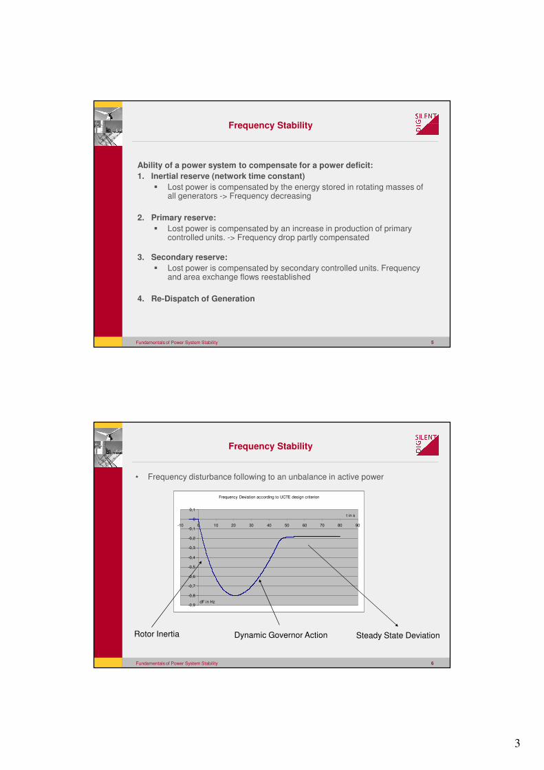
• Frequency disturbance following to an unbalance in active power
Frequency Deviation according to UCTE design criterion
-0,9
-0,8
-0,7
-0,6
-0,5
-0,4
-0,3
-0,2
-0,1
0
0,1
-10 0 10 20 30 40 50 60 70 80 90
dF in Hz
t in s
Rotor Inertia Dynamic Governor Action Steady State Deviation
Frequency Stability
4
Fundamentals of Power System Stability 7
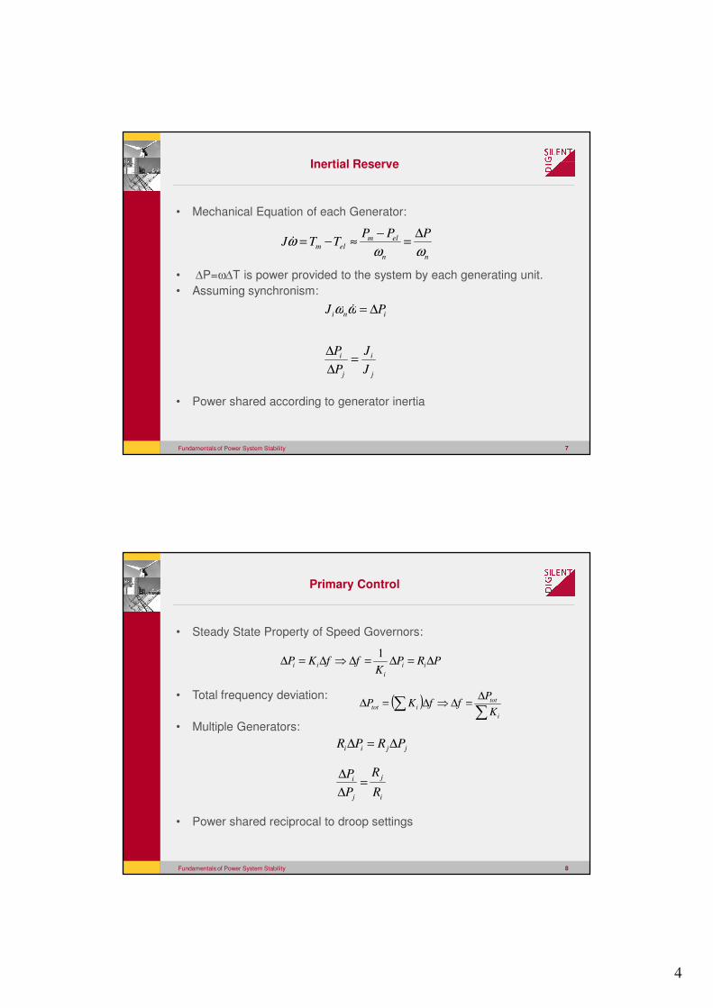
• Mechanical Equation of each Generator:
• ∆P=ω∆T is power provided to the system by each generating unit.
• Assuming synchronism:
• Power shared according to generator inertia
nn
elmelm
PPPTTJ
ωωω
∆=
−≈−=�
j
i
j
i
ini
J
J
P
P
PJ
=∆
∆
∆=ωω �
Inertial Reserve
Fundamentals of Power System Stability 8
• Steady State Property of Speed Governors:
• Total frequency deviation:
• Multiple Generators:
• Power shared reciprocal to droop settings
( )∑
∑∆
=∆⇒∆=∆i
totitot
K
PffKP
i
j
j
i
jjii
R
R
P
P
PRPR
=∆
∆
∆=∆
PRPK
ffKP ii
i
ii ∆=∆=∆⇒∆=∆1
Primary Control
5
Fundamentals of Power System Stability 9
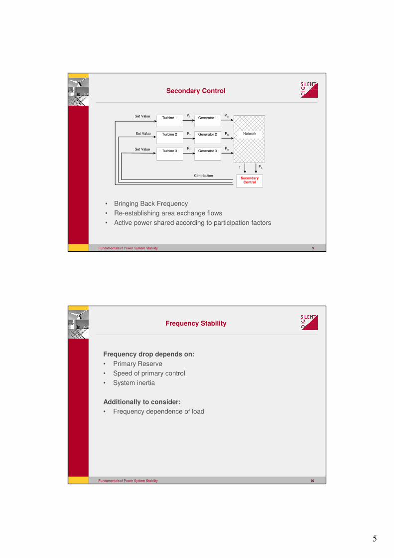
Turbine 1
Turbine 2
Turbine 3
Generator 1
Generator 2
Generator 3
Network
Secondary Control
PT PG
PT PG
PT PG
f PA
Set Value
Set Value
Set Value
Contribution
• Bringing Back Frequency
• Re-establishing area exchange flows
• Active power shared according to participation factors
Secondary Control
Fundamentals of Power System Stability 10
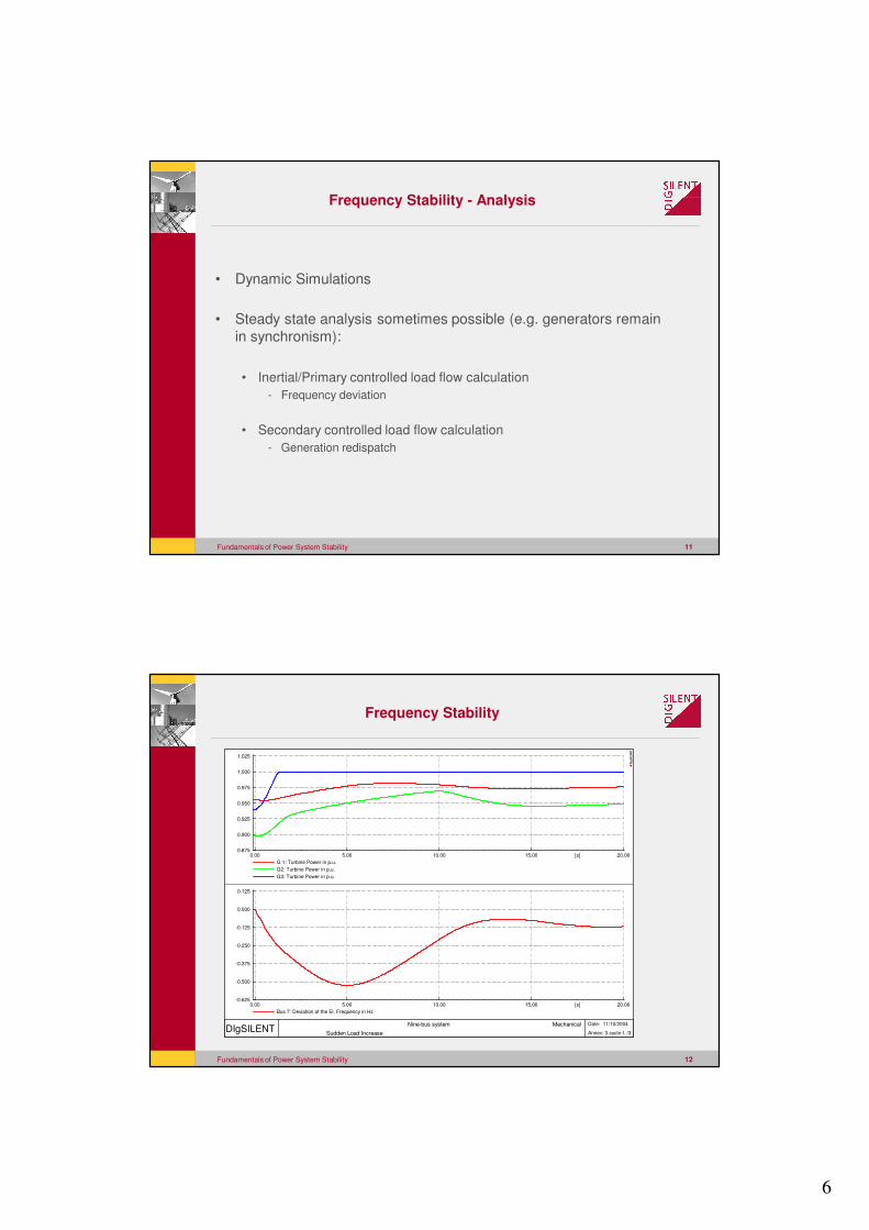
Frequency drop depends on:
• Primary Reserve
• Speed of primary control
• System inertia
Additionally to consider:
• Frequency dependence of load
Frequency Stability
6
Fundamentals of Power System Stability 11
• Dynamic Simulations
• Steady state analysis sometimes possible (e.g. generators remain
in synchronism):
• Inertial/Primary controlled load flow calculation
- Frequency deviation
• Secondary controlled load flow calculation
- Generation redispatch
Frequency Stability - Analysis
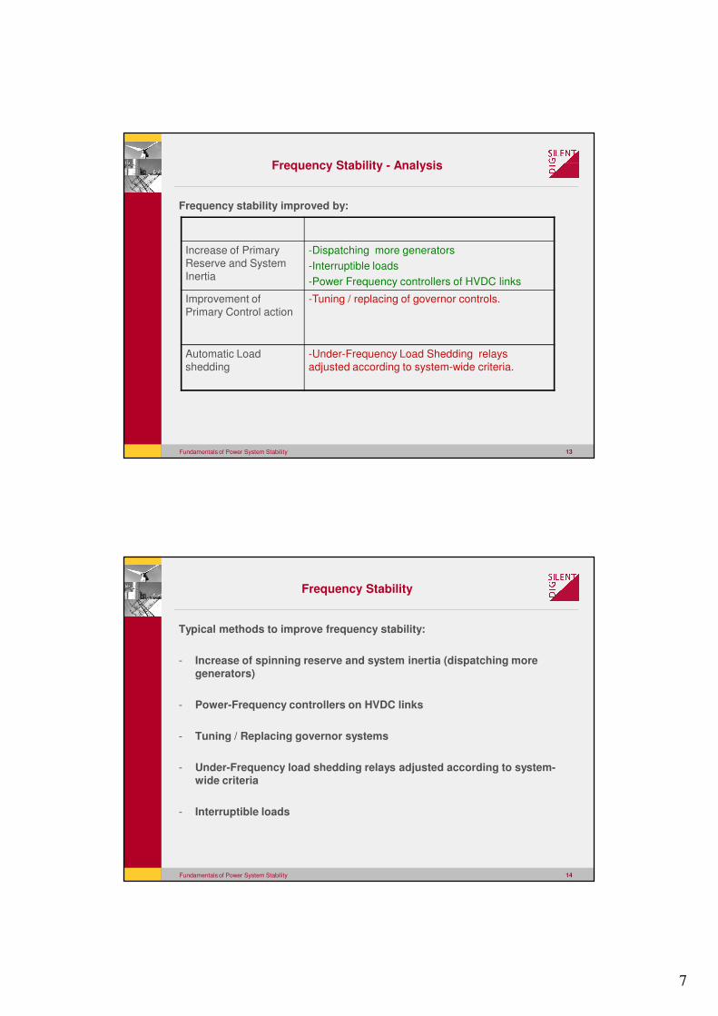
Fundamentals of Power System Stability 12
20.0015.0010.005.000.00 [s]
1.025
1.000
0.975
0.950
0.925
0.900
0.875
G 1: Turbine Power in p.u.
G2: Turbine Power in p.u.
G3: Turbine Power in p.u.
20.0015.0010.005.000.00 [s]
0.125
0.000
-0.125
-0.250
-0.375
-0.500
-0.625
Bus 7: Deviation of the El. Frequency in Hz
DIgSILENT Nine-bus system Mechanical
Sudden Load Increase
Date: 11/10/2004
Annex: 3-cycle-f. /3
DIg
SIL
EN
T
Frequency Stability
7
Fundamentals of Power System Stability 13
Frequency Stability - Analysis
Frequency stability improved by:
Increase of Primary
Reserve and System
Inertia
-Dispatching more generators
-Interruptible loads
-Power Frequency controllers of HVDC links
Improvement of
Primary Control action
-Tuning / replacing of governor controls.
Automatic Load
shedding
-Under-Frequency Load Shedding relays
adjusted according to system-wide criteria.
Fundamentals of Power System Stability 14
Frequency Stability
Typical methods to improve frequency stability:
- Increase of spinning reserve and system inertia (dispatching more generators)
- Power-Frequency controllers on HVDC links
- Tuning / Replacing governor systems
- Under-Frequency load shedding relays adjusted according to system-wide criteria
- Interruptible loads
8
Fundamentals of Power System Stability 15
Rotor Angle Stability
Fundamentals of Power System Stability 16
Two distinctive types of rotor angle stability:
- Small signal rotor angle stability (Oscillatory stability)
- Large signal rotor angle stability (Transient stability)
Rotor Angle Stability
9
Fundamentals of Power System Stability 17
Small signal rotor angle stability (Oscillatory stability)
Ability of a power system to maintain synchronism under small disturbances
– Damping torque
– Synchronizing torque
Especially the following oscillatory phenomena are a concern:
– Local modes
– Inter-area modes
– Control modes
– (Torsional modes)
Oscillatory Stability
Fundamentals of Power System Stability 18
Small signal rotor angle stability is a system property
Small disturbance -> analysis using linearization around operating
point
Analysis using eigenvalues and eigenvectors
Oscillatory Stability
10
Fundamentals of Power System Stability 19
Oscillatory Stability
Typical methods to improve oscillatory stability:
- Power System Stabilizers
- Supplementary control of Static Var Compensators
- Supplementary control of HVDC links
- Reduction of transmission system impedance ( for inter-area oscillations, by addition of lines, series capacitors, etc.)
Fundamentals of Power System Stability 20
Large signal rotor angle stability (Transient stability)
Ability of a power system to maintain synchronism during severe
disturbances
– Critical fault clearing time
Large signal stability depends on system properties and the type
of disturbance (not only a system property)
– Analysis using time domain simulations
Transient Stability

11
Fundamentals of Power System Stability 21
3.2342.5871.9401.2940.650.00 [s]
200.00
100.00
0.00
-100.00
-200.00
G1: Rotor angle with reference to reference machine angle in deg
DIgSILENT Transient Stability Subplot/Diagramm
Date: 11/11/2004
Annex: 1 /3
DIg
SIL
EN
T
4.9903.9922.9941.9961.000.00 [s]
25.00
12.50
0.00
-12.50
-25.00
-37.50
G1: Rotor angle with reference to reference machine angle in deg
DIgSILENT Transient Stability Subplot/Diagramm
Date: 11/11/2004
Annex: 1 /3
DIg
SIL
EN
T
Transient Stability
Fundamentals of Power System Stability 22
Transient Stability
Typical methods to improve transient stability:
- Reduction of transmission system impedance (additional lines, series capacitors, etc.).
- High speed fault clearing.
- Single-pole breaker action.
- Voltage control ( SVS, reactor switching, etc.).
- Improved excitation systems ( high speed systems, transient excitation boosters, etc.).
- Remote generator and load tripping.
- Controls on HVDC transmission links.

12
Fundamentals of Power System Stability 23
Voltage Stability
Fundamentals of Power System Stability 24
Voltage stability refers to the ability of a power system to
maintain steady voltages at all buses in the system after being
subjected to a disturbance.
• Small disturbance voltage stability (Steady state stability)
– Ability to maintain steady voltages when subjected to small
disturbances
• Large disturbance voltage stability (Dynamic voltage stability)
– Ability to maintain steady voltages after following large disturbances
Voltage Stability
13
Fundamentals of Power System Stability 25
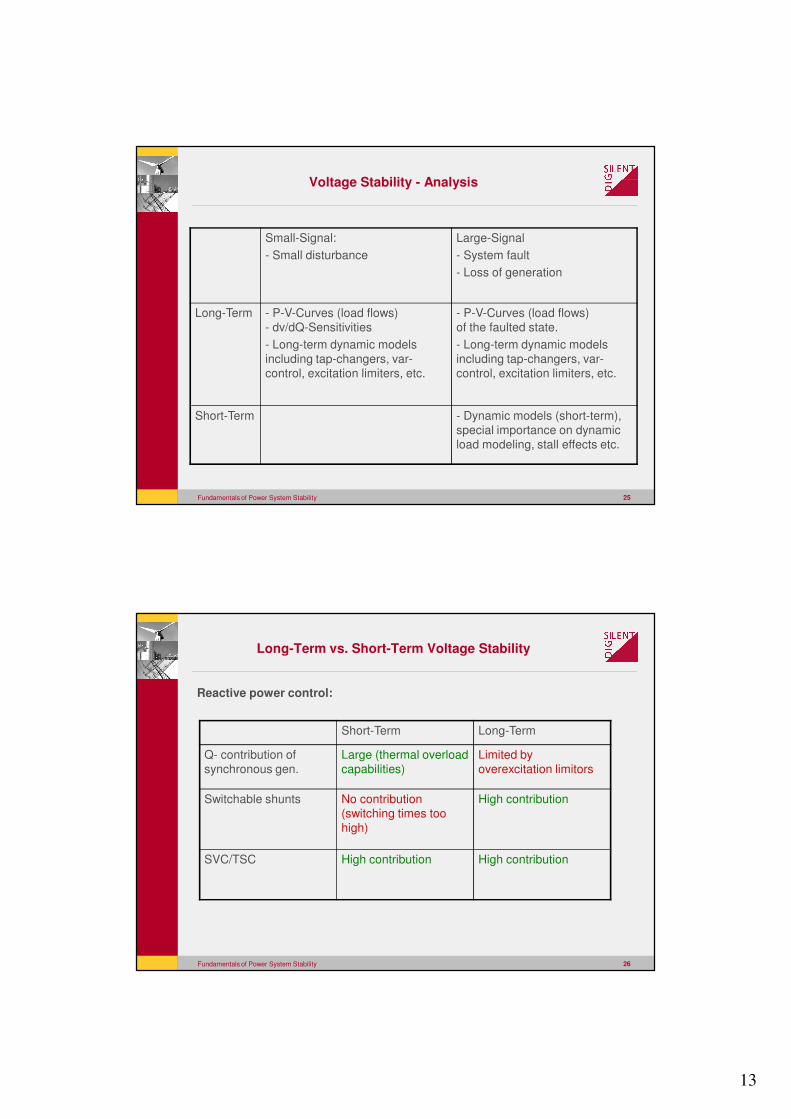
Small-Signal:
- Small disturbance
Large-Signal
- System fault
- Loss of generation
Long-Term - P-V-Curves (load flows)
- dv/dQ-Sensitivities
- Long-term dynamic models
including tap-changers, var-
control, excitation limiters, etc.
- P-V-Curves (load flows)
of the faulted state.
- Long-term dynamic models
including tap-changers, var-
control, excitation limiters, etc.
Short-Term - Dynamic models (short-term),
special importance on dynamic
load modeling, stall effects etc.
Voltage Stability - Analysis
Fundamentals of Power System Stability 26
Long-Term vs. Short-Term Voltage Stability
Reactive power control:
Short-Term Long-Term
Q- contribution of
synchronous gen.
Large (thermal overload
capabilities)
Limited by
overexcitation limitors
Switchable shunts No contribution
(switching times too
high)
High contribution
SVC/TSC High contribution High contribution
14
Fundamentals of Power System Stability 27
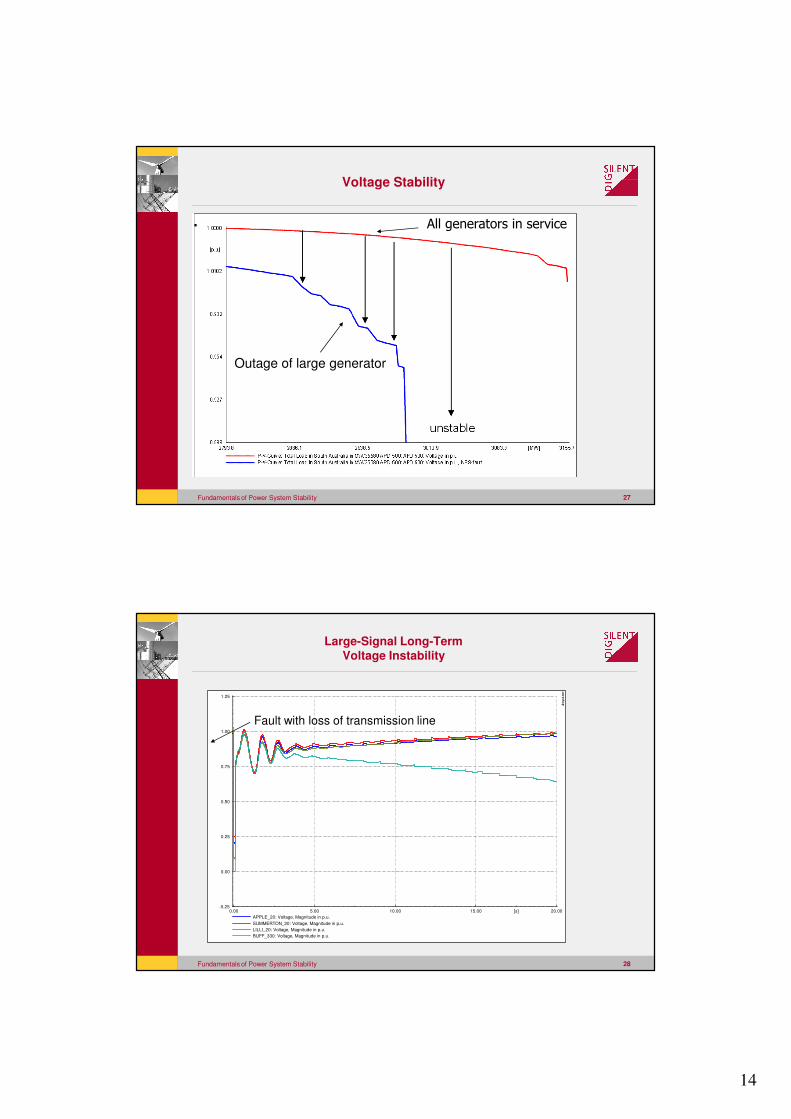
Voltage Stability
Outage of large generator
������������������� ���
Fundamentals of Power System Stability 28
20.0015.0010.005.000.00 [s]
1.25
1.00
0.75
0.50
0.25
0.00
-0.25
APPLE_20: Voltage, Magnitude in p.u.
SUMMERTON_20: Voltage, Magnitude in p.u.
LILLI_20: Voltage, Magnitude in p.u.
BUFF_330: Voltage, Magnitude in p.u.
DIg
SIL
EN
T
Fault with loss of transmission line
Large-Signal Long-TermVoltage Instability
15
Fundamentals of Power System Stability 29
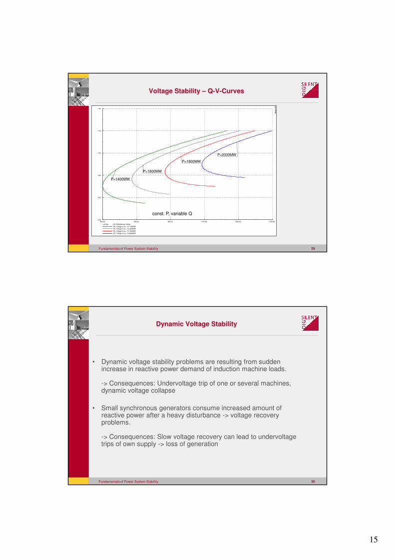
Voltage Stability – Q-V-Curves
1762.641462.641162.64862.64562.64262.64
1.40
1.20
1.00
0.80
0.60
0.40
x-Achse: SC: Blindleistung in Mvar
SC: Voltage in p.u., P=1400MW
SC: Voltage in p.u., P=1600MW
SC: Voltage in p.u., P=1800MW
SC: Voltage in p.u., P=2000MW
P=2000MW
P=1800MW
P=1600MW
P=1400MW
DIg
SIL
EN
T
const. P, variable Q
Fundamentals of Power System Stability 30
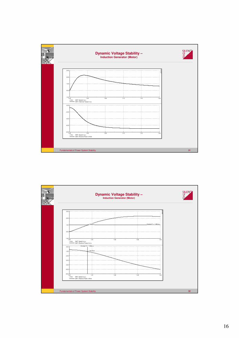
• Dynamic voltage stability problems are resulting from sudden increase in reactive power demand of induction machine loads.
-> Consequences: Undervoltage trip of one or several machines, dynamic voltage collapse
• Small synchronous generators consume increased amount of reactive power after a heavy disturbance -> voltage recovery problems.
-> Consequences: Slow voltage recovery can lead to undervoltage trips of own supply -> loss of generation
Dynamic Voltage Stability
16
Fundamentals of Power System Stability 31
1.201.161.121.081.041.00
3.00
2.00
1.00
0.00
-1.00
x-Axis: GWT: Speed in p.u.
GWT: Electrical Torque in p.u.
1.201.161.121.081.041.00
0.00
-2.00
-4.00
-6.00
-8.00
x-Axis: GWT: Speed in p.u.
GWT: Reactive Power in Mvar
DIg
SIL
EN
T
Dynamic Voltage Stability –Induction Generator (Motor)
Fundamentals of Power System Stability 32
1.041.031.021.011.00
3.00
2.00
1.00
0.00
-1.00
x-Axis: GWT: Speed in p.u.
GWT: Electrical Torque in p.u.
Constant Y = 1.000 p.u. 1.008 p.u.
1.041.031.021.011.00
0.00
-1.00
-2.00
-3.00
-4.00
-5.00
-6.00
x-Axis: GWT: Speed in p.u.
GWT: Reactive Power in Mvar
Constant X = 1.008 p.u.
-1.044 Mvar
DIg
SIL
EN
T
Dynamic Voltage Stability –Induction Generator (Motor)
17
Fundamentals of Power System Stability 33
2.001.501.000.500.00 [s]
1.20
1.00
0.80
0.60
0.40
0.20
0.00
G\HV: Voltage, Magnitude in p.u.
MV: Voltage, Magnitude in p.u.
2.001.501.000.500.00 [s]
80.00
40.00
0.00
-40.00
-80.00
-120.00
Cub_0.1\PQ PCC: Active Power in p.u.
Cub_0.1\PQ PCC: Reactive Power in p.u.
2.001.501.000.500.00 [s]
1.06
1.04
1.02
1.00
0.98
GWT: Speed
DIg
SIL
EN
T
Dynamic Voltage Stability –Induction Generator (Motor)
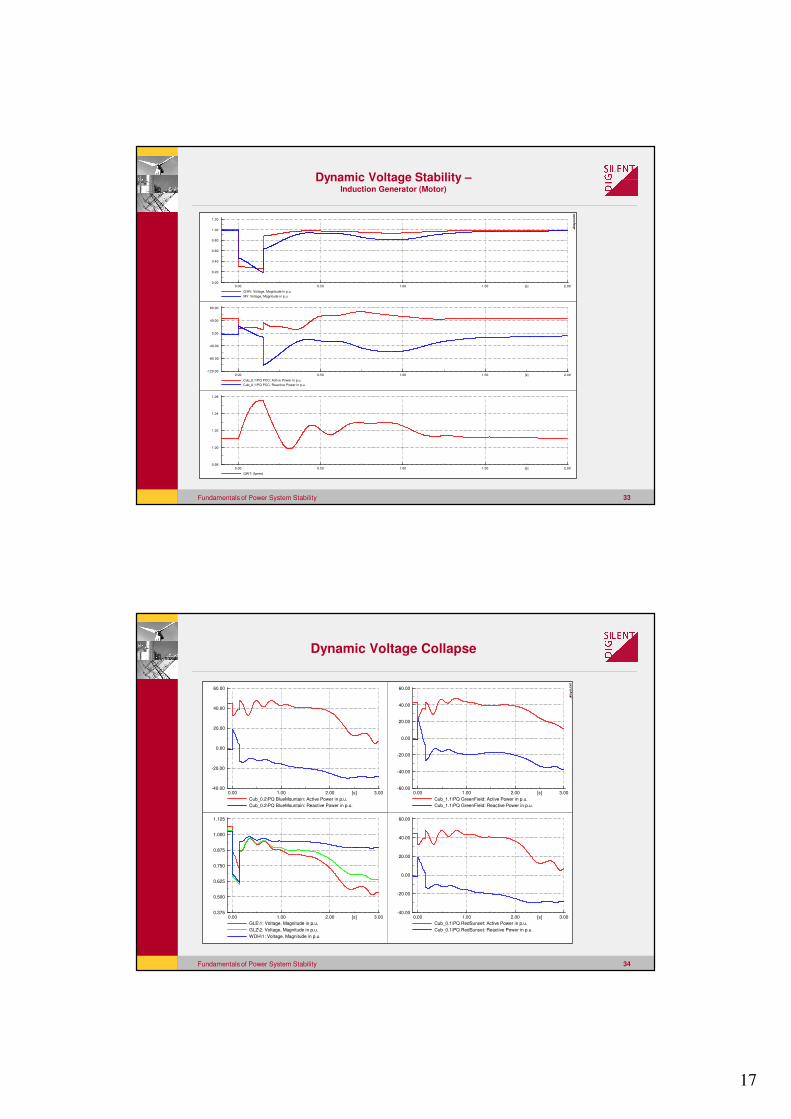
Fundamentals of Power System Stability 34
3.002.001.000.00 [s]
60.00
40.00
20.00
0.00
-20.00
-40.00
Cub_0.1\PQ RedSunset: Active Power in p.u.
Cub_0.1\PQ RedSunset: Reactive Power in p.u.
3.002.001.000.00 [s]
60.00
40.00
20.00
0.00
-20.00
-40.00
Cub_0.2\PQ BlueMountain: Active Power in p.u.
Cub_0.2\PQ BlueMountain: Reactive Power in p.u.
3.002.001.000.00 [s]
60.00
40.00
20.00
0.00
-20.00
-40.00
-60.00
Cub_1.1\PQ GreenField: Active Power in p.u.
Cub_1.1\PQ GreenField: Reactive Power in p.u.
3.002.001.000.00 [s]
1.125
1.000
0.875
0.750
0.625
0.500
0.375
GLE\1: Voltage, Magnitude in p.u.
GLZ\2: Voltage, Magnitude in p.u.
WDH\1: Voltage, Magnitude in p.u.
DIg
SIL
EN
T
Dynamic Voltage Collapse
18
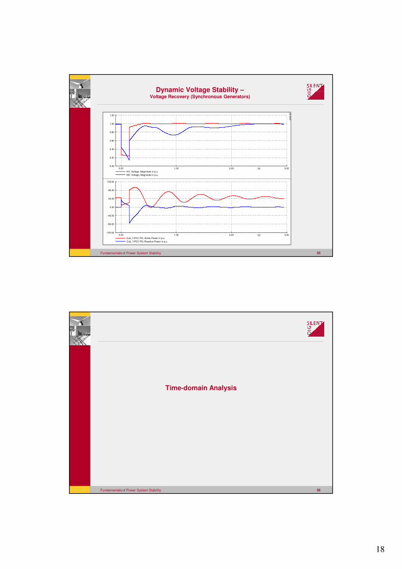
Fundamentals of Power System Stability 35
3.002.001.000.00 [s]
1.20
1.00
0.80
0.60
0.40
0.20
0.00
HV: Voltage, Magnitude in p.u.
MV: Voltage, Magnitude in p.u.
3.002.001.000.00 [s]
120.00
80.00
40.00
0.00
-40.00
-80.00
-120.00
Cub_1\PCC PQ: Active Power in p.u.
Cub_1\PCC PQ: Reactive Power in p.u.
DIg
SIL
EN
T
Dynamic Voltage Stability –Voltage Recovery (Synchronous Generators)
Fundamentals of Power System Stability 36
Time-domain Analysis
19
Fundamentals of Power System Stability 37
Fast Transients/Network Transients:
Time frame: 10 mys…..500ms
� Lightening
� Switching Overvoltages
� Transformer Inrush/Ferro Resonance
� Decaying DC-Components of short circuit currents
Transients in Power Systems
Fundamentals of Power System Stability 38
Medium Term Transients / Electromechanical Transients
Time frame: 400ms….10s
� Transient Stability
� Critical Fault Clearing Time
� AVR and PSS
� Turbine and governor
� Motor starting
� Load Shedding
Transients in Power Systems
20
Fundamentals of Power System Stability 39
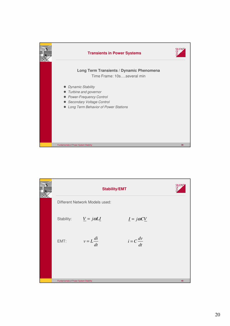
Long Term Transients / Dynamic Phenomena
Time Frame: 10s….several min
� Dynamic Stability
� Turbine and governor
� Power-Frequency Control
� Secondary Voltage Control
� Long Term Behavior of Power Stations
Transients in Power Systems
Fundamentals of Power System Stability 40
Stability/EMT
Different Network Models used:
Stability:
EMT:
ILjV ω= VCjI ω=
dt
diLv =
dt
dvCi =
21
Fundamentals of Power System Stability 41
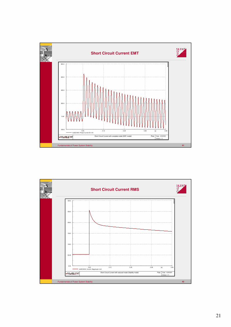
Short Circuit Current EMT
0.50 0.38 0.25 0.12 0.00 [s]
800.0
600.0
400.0
200.0
0.00
-200.0
4x555 MVA: Phase Current B in kA
Short Circuit Current with complete model (EMT-model) Plots
Date: 4/25/2001
Annex: 1 /1
DIg
SIL
EN
T
Fundamentals of Power System Stability 42
Short Circuit Current RMS
0.50 0.38 0.25 0.12 0.00 [s]
300.0
250.0
200.0
150.0
100.0
50.00
0.00
4x555 MVA: Current, Magnitude in kA
Short Circuit Current with reduced model (Stability model) Plots
Date: 4/25/2001
Annex: 1 /1
DIg
SIL
EN
T
22
Fundamentals of Power System Stability 43
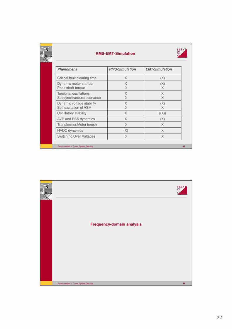
Phenomena RMS-Simulation EMT-Simulation
Critical fault clearing time X (X)
Dynamic motor startup
Peak shaft-torque
X
0
(X)
X
Torsional oscillations
Subsynchronous resonance
X
0
X
X
Dynamic voltage stability
Self excitation of ASM
X
0
(X)
X
Oscillatory stability X ((X))
AVR and PSS dynamics X (X)
Transformer/Motor inrush 0 X
HVDC dynamics (X) X
Switching Over Voltages 0 X
RMS-EMT-Simulation
Fundamentals of Power System Stability 44
Frequency-domain analysis
23
Fundamentals of Power System Stability 45
Small signal stability analysis
• Small signal stability is the ability of the power system to maintain
synchronism when subjected to small disturbances.
• Disturbance is considered to be small when equation describing the response
can be linearized.
• Instability may result as: steady increase in rotor angle (lack of synchronizing
torque) or rotor oscillations of increasing amplitude (lack of damping torque)
Fundamentals of Power System Stability 46
Small signal stability analysis
• Linear model generated numerically by Power Factory.
• Calculation of eigenvalues, eigenvectors and participation factors
• Calculation of all modes using QR-algorithm -> limited to systems up to
500..1000 state variables
• Calculation of selected modes using implicitly restarted Arnoldi method ->
application to large systems
24
Fundamentals of Power System Stability 47
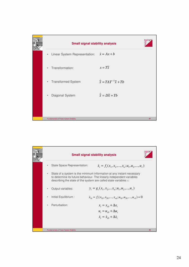
Small signal stability analysis
• Linear System Representation:
• Transformation:
• Transformed System
• Diagonal System
bAxx +=�
xTx ~=
TbxTATx += − ~~ 1�
TbxDx += ~~�
Fundamentals of Power System Stability 48
Small signal stability analysis
• State Space Representation:
• State of a system is the minimum information at any instant necessary
to determine its future behaviour. The linearly independent variables
describing the state of the system are called state variables x.
• Output variables:
• Initial Equilibrium :
• Perturbation:
),...,,;,...,,( 2121 rnii uuuxxxfx =�
),...,,;,...,( 2121 rnii uuuxxxgy =
iii
iii
iii
xxx
uuu
xxx
��� ∆+=
∆+=
∆+=
0
0
0
0),...,,;,...,,( 02010020100== rnii uuuxxxfx�
25
Fundamentals of Power System Stability 49
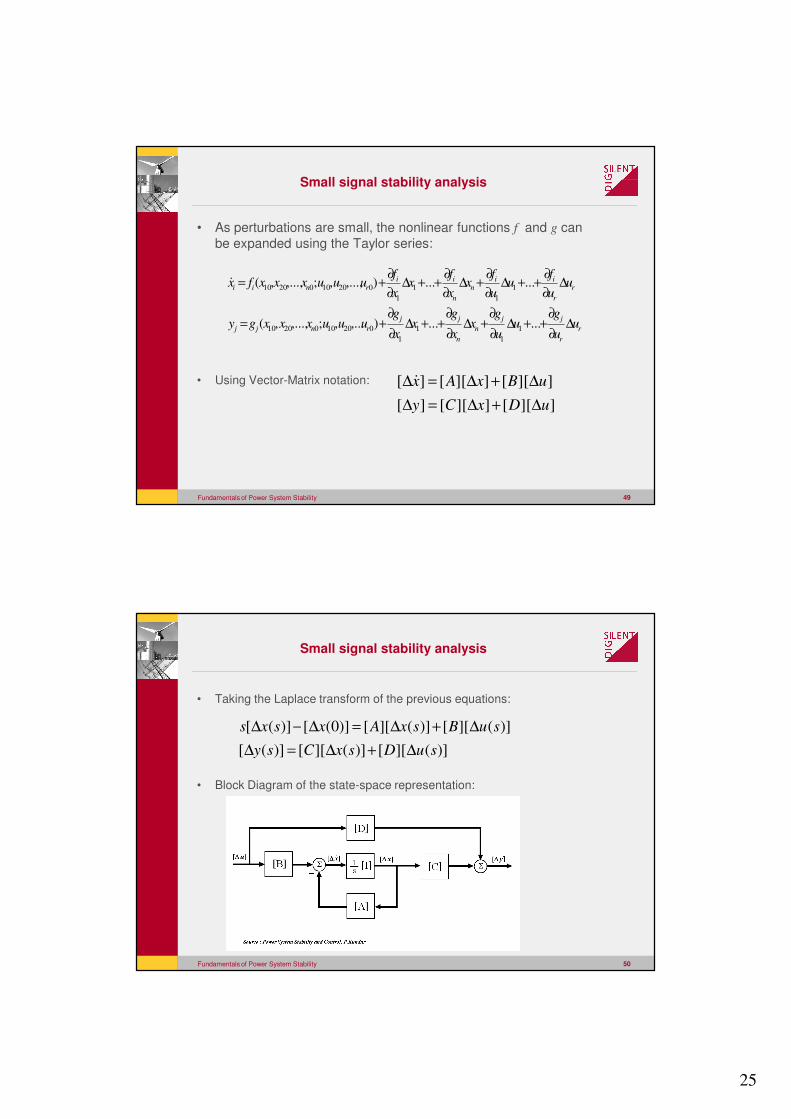
Small signal stability analysis
• As perturbations are small, the nonlinear functions f and g can
be expanded using the Taylor series:
• Using Vector-Matrix notation:
r
r
jj
n
n
jj
rnjj
r
r
iin
n
iirnii
uu
gu
u
gx
x
gx
x
guuuxxxgy
uu
fu
u
fx
x
fx
x
fuuuxxxfx
∆∂
∂++∆
∂
∂+∆
∂
∂++∆
∂
∂+=
∆∂
∂++∆
∂
∂+∆
∂
∂++∆
∂
∂+=
......),...,;,...,,(
......),...,,;,...,,(
1
1
1
1
0201002010
1
1
1
1
0201002010�
]][[]][[][
]][[]][[][
uDxCy
uBxAx
∆+∆=∆
∆+∆=∆�
Fundamentals of Power System Stability 50
Small signal stability analysis
• Taking the Laplace transform of the previous equations:
• Block Diagram of the state-space representation:
)](][[)](][[)]([
)](][[)](][[)]0([)]([
suDsxCsy
suBsxAxsxs
∆+∆=∆
∆+∆=∆−∆
26
Fundamentals of Power System Stability 51
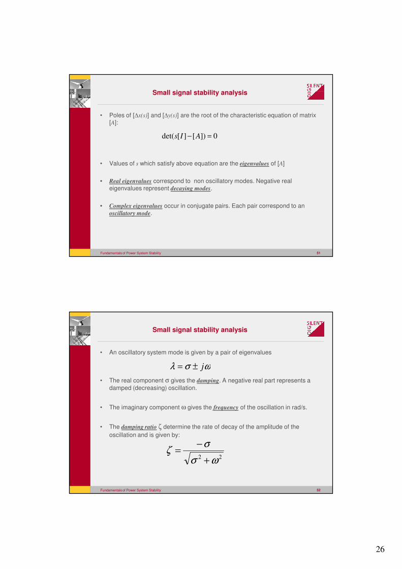
Small signal stability analysis
• Poles of [∆x(s)] and [∆y(s)] are the root of the characteristic equation of matrix
[A]:
• Values of s which satisfy above equation are the eigenvalues of [A]
• Real eigenvalues correspond to non oscillatory modes. Negative real
eigenvalues represent decaying modes.
• Complex eigenvalues occur in conjugate pairs. Each pair correspond to an
oscillatory mode.
0])[][det( =− AIs
Fundamentals of Power System Stability 52
Small signal stability analysis
• An oscillatory system mode is given by a pair of eigenvalues
• The real component σ gives the damping. A negative real part represents a
damped (decreasing) oscillation.
• The imaginary component ω gives the frequency of the oscillation in rad/s.
• The damping ratio ζ determine the rate of decay of the amplitude of the
oscillation and is given by:
ωσλ j±=
22 ωσ
σζ
+
−=
27
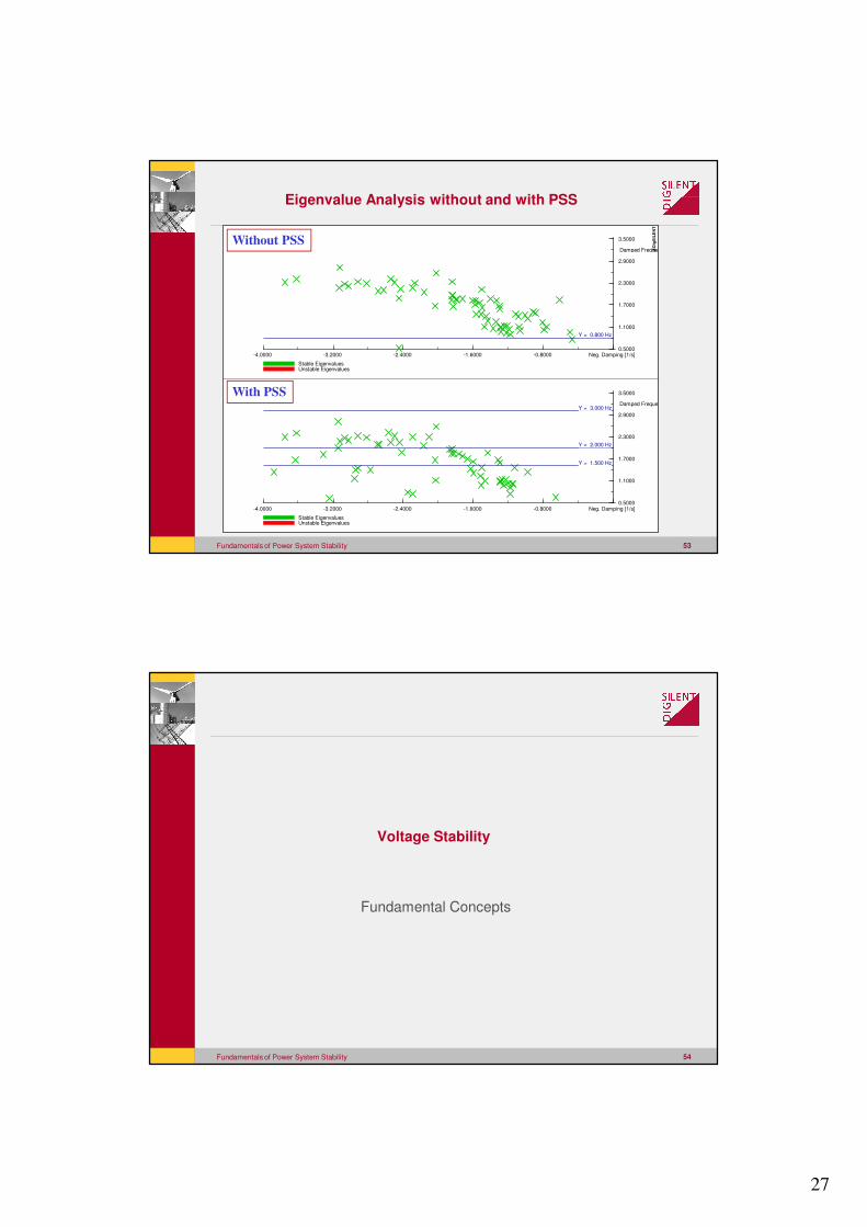
Fundamentals of Power System Stability 53
-0.8000-1.6000-2.4000-3.2000-4.0000 Neg. Damping [1/s]
3.5000
2.9000
2.3000
1.7000
1.1000
0.5000
Damped Frequen
Stable EigenvaluesUnstable Eigenvalues
Y = 1.500 Hz
Y = 2.000 Hz
Y = 3.000 Hz
-0.8000-1.6000-2.4000-3.2000-4.0000 Neg. Damping [1/s]
3.5000
2.9000
2.3000
1.7000
1.1000
0.5000
Damped Frequen
Stable EigenvaluesUnstable Eigenvalues
Y = 0.800 Hz
DIg
SIL
EN
T
Eigenvalue Analysis without and with PSS
Without PSS
With PSS
Fundamentals of Power System Stability 54
Voltage Stability
Fundamental Concepts
28
Fundamentals of Power System Stability 55
0E
eQX
'
GE
( )
( )( )GGG
e
GG
e
EEX
EQ
X
EEP
ϕ
ϕ
cos
sin
0
''
'
0
−=
=
Voltage Stability
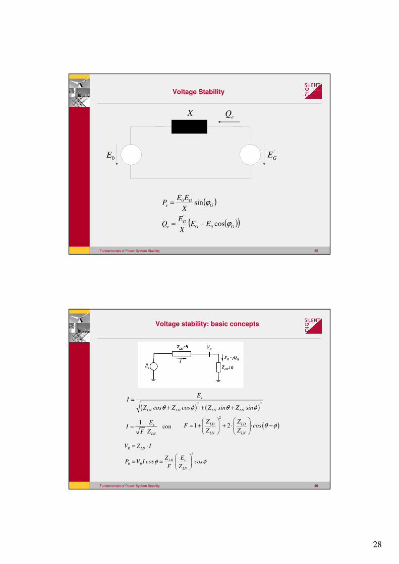
Fundamentals of Power System Stability 56
Voltage stability: basic concepts
( ) ( )2 2
s
LN LD LN LD
EI
Z cos Z cos Z sin Z sinθ φ θ φ=
+ + +
1 s
LN
EI
ZF= ( )
2
1 2LD LD
LN LN
Z ZF cos
Z Zθ φ
= + + ⋅ ⋅ −
2
R LD
sLDR R
LN
V Z I
EZP V I cos cos
F Zφ φ
= ⋅
= =
con
29
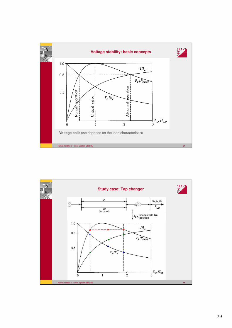
Fundamentals of Power System Stability 57
Voltage stability: basic concepts
Voltage collapse depends on the load characteristics
Fundamentals of Power System Stability 58
Study case: Tap changer
30
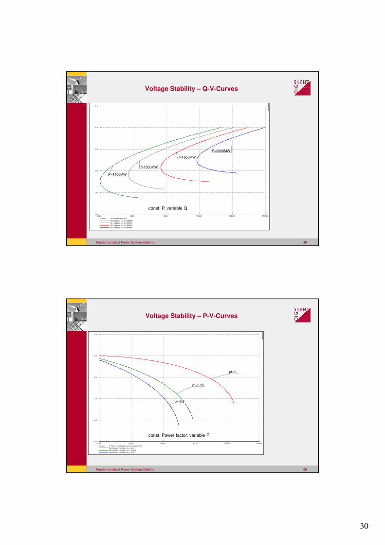
Fundamentals of Power System Stability 59
1762.641462.641162.64862.64562.64262.64
1.40
1.20
1.00
0.80
0.60
0.40
x-Achse: SC: Blindleistung in Mvar
SC: Voltage in p.u., P=1400MW
SC: Voltage in p.u., P=1600MW
SC: Voltage in p.u., P=1800MW
SC: Voltage in p.u., P=2000MW
P=2000MW
P=1800MW
P=1600MW
P=1400MW
DIg
SIL
EN
T
const. P, variable Q
Voltage Stability – Q-V-Curves
Fundamentals of Power System Stability 60
1350.001100.00850.00600.00350.00100.00
1.00
0.90
0.80
0.70
0.60
0.50
x-Achse: U_P-Curve: Total Load of selected loads in MW
Klemmleiste(1): Voltage in p.u., pf=1
Klemmleiste(1): Voltage in p.u., pf=0.95
Klemmleiste(1): Voltage in p.u., pf=0.9
pf=1
pf=0.95
pf=0.9
DIg
SIL
EN
T
const. Power factor, variable P
Voltage Stability – P-V-Curves
31
Fundam
enta
ls of P
ow
er S
yste
m S
tability
61
Ro
tor A
ng
le S
tab
ility
Fundam
enta
ls of P
ow
er S
yste
m S
tability
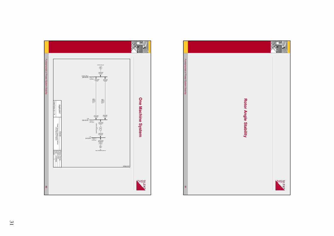
62
On
e M
ach
ine S
yste
m
DIg
SIL
EN
T
Pow
erF
acto
ry 12
.1.1
78
Exa
mp
le
Pow
er S
yste
m S
tab
ility an
d C
on
trol
On
e M
ach
ine P
rob
lem
Pro
ject: T
rain
ing
Gra
ph
ic: G
rid
Date
: 4/1
9/2
00
2
An
nex: 1
G~
G1Gen 2220MVA/24kV(1)
1998.000 MW967.920 Mvar
53.408 kA1.163 p.u.-0.000 p.u.
Trf
50
0kV
/24
kV
/22
20
MV
A
-1998.00 MW-634.89 Mvar
2.56 kA
1998.00 MW967.92 Mvar
53.41 kA
CC
T 2
Type
CC
T1
86
.00
km
-698.60 MW30.44 Mvar
0.90 kA
698.60 MW221.99 Mvar
0.90 kA
CC
T1
Type
CC
T1
00
.00
km
-1299.40 MW56.62 Mvar
1.67 kA
1299.40 MW412.90 Mvar
1.67 kA
V~
Infinite Source
-1998.00 MW87.07 Mvar
2.56 kA
Infinite Bus500.00 kV 450.41 kV
0.90 p.u.0.00 deg
HT500.00 kV 472.15 kV
0.94 p.u.20.12 deg
LT24.00 kV 24.00 kV
1.00 p.u.28.34 deg
DIgSILENT
32
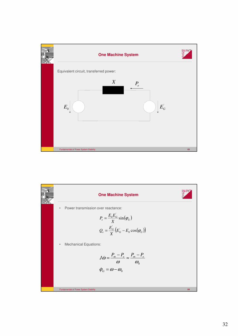
Fundamentals of Power System Stability 63
One Machine System
0E
ePX
'
GE
Equivalent circuit, transferred power:
Fundamentals of Power System Stability 64
One Machine System
• Power transmission over reactance:
• Mechanical Equations:
0
0
ωωϕ
ωωω
−=
−≈
−=
G
emem PPPPJ
�
�
( )
( )( )GG
Ge
GG
e
EEX
EQ
X
EEP
ϕ
ϕ
cos
sin
0
''
'
0
−=
=
33
Fundamentals of Power System Stability 65
One Machine System
• Differential Equation of a one-machine infinite bus bar system:
• Eigenvalues (Characteristic Frequency):
• Stable Equilibrium points (SEP) exist for:
GGG
m
G
m
G
PPPPPJ ϕϕ
ωϕ
ωωϕ
ωωϕ ∆
−−≈−=
0
0
max
0
0
max
00
max
0
cossinsin��
0
0
max2/1 cos G
J
Pϕ
ωλ −±=
0cos 0 >Gϕ
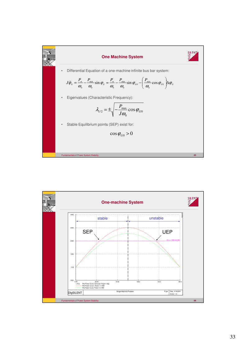
Fundamentals of Power System Stability 66
One-machine System
180.0144.0108.072.0036.00 0.00
4000.
3000.
2000.
1000.
0.00
-1000...
x-Axis: Plot Power Curve: Generator Angle in deg
Plot Power Curve: Power 1 in MW
Plot Power Curve: Power 2 in MW
Pini y=1998.000 MW
DIgSILENT Single Machine Problem P-phi
Date: 4/19/2002
Annex: 1 /4
DIg
SIL
EN
T
SEP UEP
stable unstable
34
Fundamentals of Power System Stability 67
Large disturbances (Transient Stability)
• Energy Function:
• At Maximum Angle:
( ) 0)(
2
1
0
2=+=
−+ ∫ potkin
emG EEd
PPJ
G
ϕω
ϕϕ
ϕ
�
0max
=G
ϕ�
0)(max
0
=−
= ∫ ϕω
ϕ
ϕ
dPP
EG
em
pot
( )0=kin
E
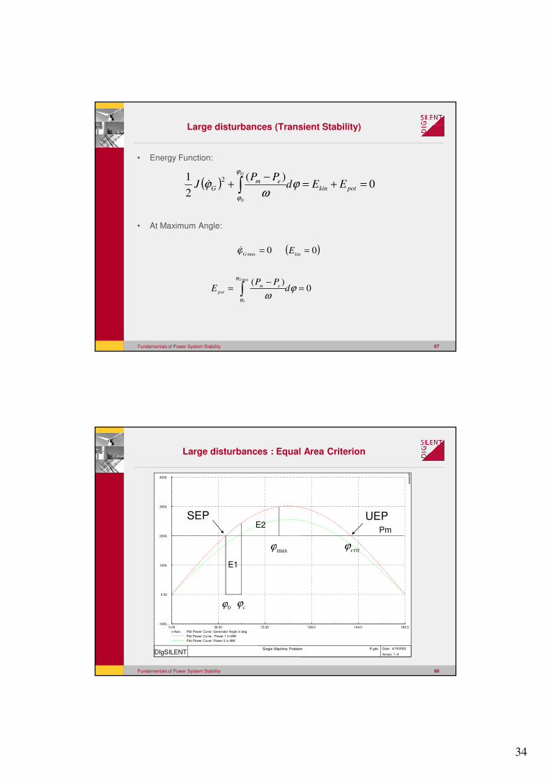
Fundamentals of Power System Stability 68
Large disturbances : Equal Area Criterion
180.0144.0108.072.0036.000.00
4000.
3000.
2000.
1000.
0.00
-1000...
x-Axis: Plot Power Curve: Generator Angle in deg
Plot Power Curve: Power 1 in MW
Plot Power Curve: Power 2 in MW
DIgSILENT Single Machine Problem P-phi Date: 4/19/2002
Annex: 1 /4
DIg
SIL
EN
T
E1
E2
0ϕ cϕ
maxϕ
SEP UEP
critϕ
Pm
35
Fundamentals of Power System Stability 69
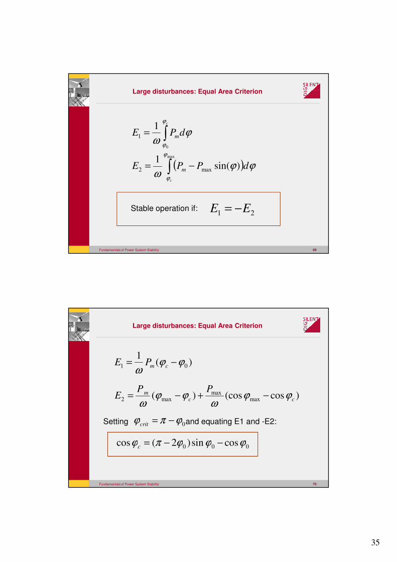
Large disturbances: Equal Area Criterion
21 EE −=
∫=c
dPE m
ϕ
ϕ
ϕω
0
11
( )∫ −=max
)sin(1
max2
ϕ
ϕ
ϕϕω
c
dPPE m
Stable operation if:
Fundamentals of Power System Stability 70
Large disturbances: Equal Area Criterion
)(1
01 ϕϕω
−= cmPE
)cos(cos)( maxmax
max2 ccm PP
E ϕϕω
ϕϕω
−+−=
000 cossin)2(cos ϕϕϕπϕ −−=c
Setting and equating E1 and -E2:0ϕπϕ −=crit
36
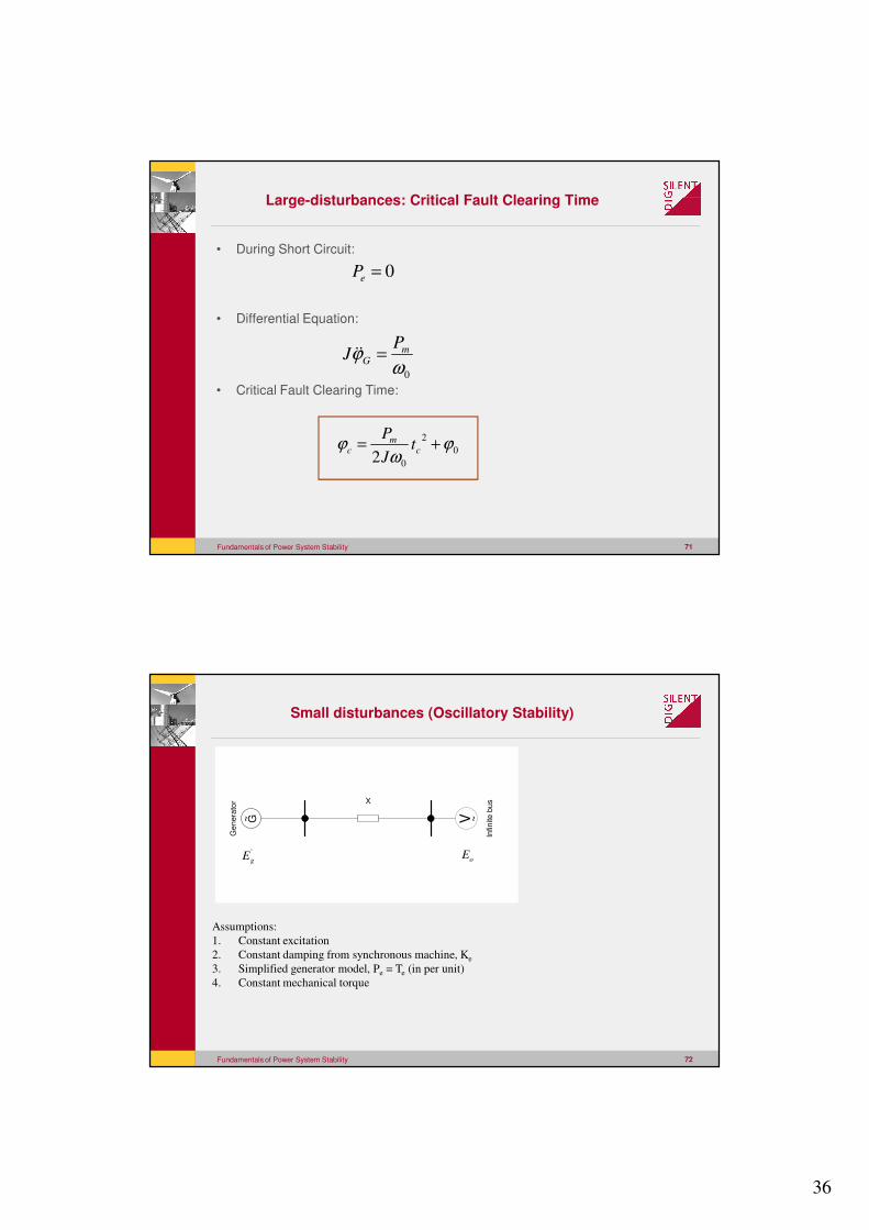
Fundamentals of Power System Stability 71
Large-disturbances: Critical Fault Clearing Time
• During Short Circuit:
• Differential Equation:
• Critical Fault Clearing Time:
0
2
02ϕ
ωϕ += c
mc t
J
P
0=eP
0ωϕ m
G
PJ =��
Fundamentals of Power System Stability 72
Small disturbances (Oscillatory Stability)
G~
Ge
ne
rato
r X
V ~
Infin
ite
bu
s
Assumptions:
1. Constant excitation
2. Constant damping from synchronous machine, Ke
3. Simplified generator model, Pe = Te (in per unit)
4. Constant mechanical torque
'
gE oE
37
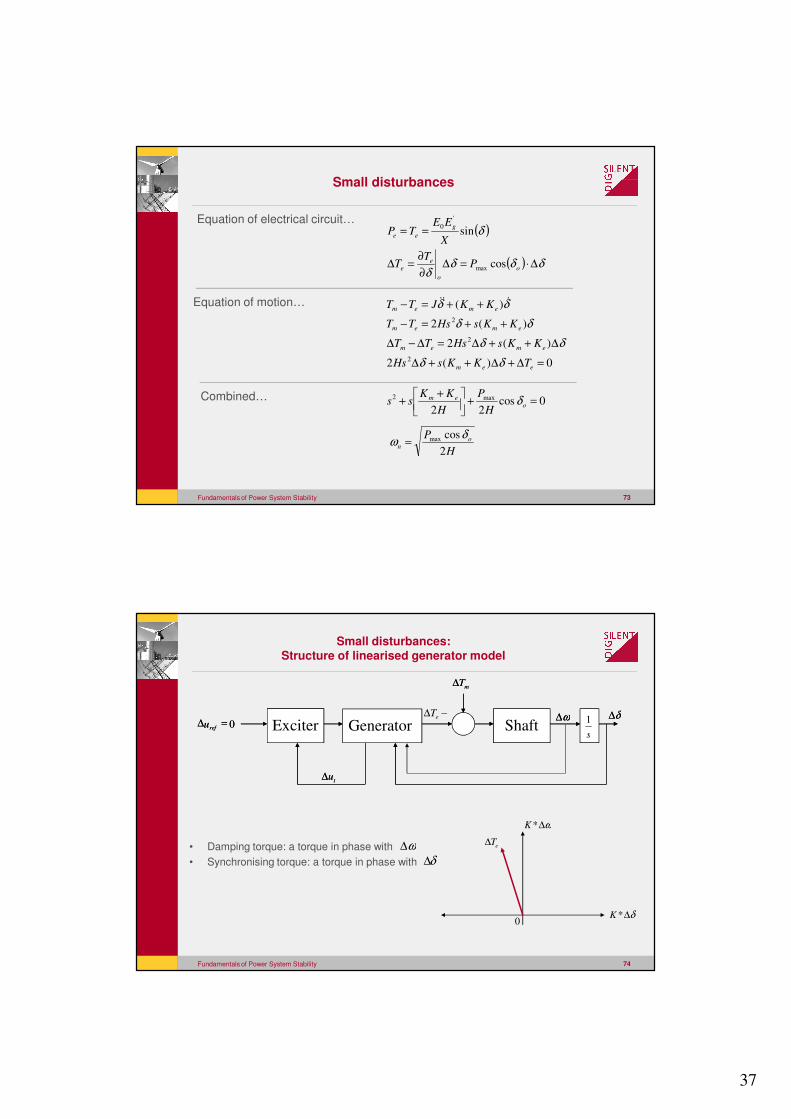
Fundamentals of Power System Stability 73
Small disturbances
( )
( ) δδδδ
δ
∆⋅=∆∂
∂=∆
==
o
o
ee
g
ee
PT
T
X
EETP
cos
sin
max
'
0Equation of electrical circuit…
Equation of motion…
0)(2
)(2
)(2
)(
2
2
2
=∆+∆++∆
∆++∆=∆−∆
++=−
++=−
eem
emem
emem
emem
TKKsHs
KKsHsTT
KKsHsTT
KKJTT
δδ
δδ
δδ
δδ ���
Combined… 0cos22
max2 =+
++ o
em
H
P
H
KKss δ
H
P on
2
cosmax δω =
Fundamentals of Power System Stability 74
Small disturbances:Structure of linearised generator model
δ∆*K0
eT∆
ω∆*K
• Damping torque: a torque in phase with
• Synchronising torque: a torque in phase with
ω∆
δ∆
Exciter Generator Shafts
1
mT∆
−∆ eT ω∆ δ∆
tu∆
0=∆refu Exciter Generator Shaft
s
1
mT∆
ω∆ δ∆
tu∆
0=∆refu
38
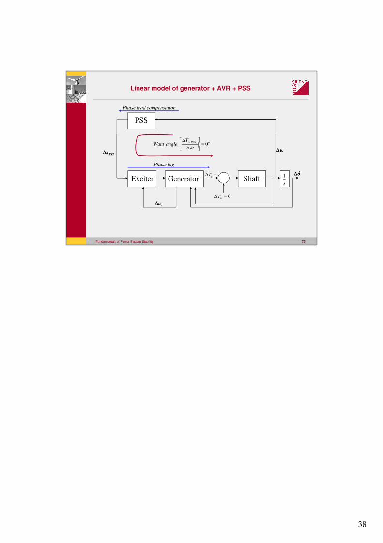
Fundamentals of Power System Stability 75
Linear model of generator + AVR + PSS
PSSu∆
Exciter Generator Shafts
1
ω∆
δ∆
tu∆
PSSu∆
Exciter Generator Shafts
1
0=∆ mT
−∆ eT
ω∆
δ∆
tu∆
PSS
oPSSeTangleWant 0
)(=
∆
∆
ω
Phase lag
Phase lead compensation