advances in waterproofing materials & technology volume 5_no 1 final.pdf · on “advances in...
TRANSCRIPT

V o l . 5 N o . 1 ( J a n - M a r 2 0 1 1 ) A Q u a r t e r l y N e w s l e t t e r
ADVANCES IN WATERPROOFING
MATERIALS & TECHNOLOGY

In Waterproofing White is Green!
Leaks and dampness in walls, ceilings, roofs, etc. can certainly be prevented. It is important to appreciate that in a country like ours with its seasonal heavy rainfall, efficient waterproofing of structures should receive the utmost attention right at the time of construction itself. Many builders tend to neglect this primary precaution, notwithstanding the fact that the pre-monsoon repairs soon turn out to be more expensive than pre-planned preventive measures during construction.
In recent times the increasing cost of new construction as well as of repairs and restoration of constructed buildings, led essentially by escalating raw materials and labour costs, is making project developers and owners opt for effective and advanced waterproofing products and solutions. There is also an increasing perception amongst the project developers and owners that the long-lasting concrete structures alone should not suffice. The requirement of waterproofing should be coupled with “aesthetics” and also with the “environmental demands”.
Crystalline waterproofing materials and flexible membrane waterproofing systems are the two versatile systems that are applied in India and internationally. While the former is used to waterproof and rehabilitate leaky water tanks, swimming pools, retaining walls, etc., the flexible membrane waterproofing systems are mainly applied to waterproof roofs and other exteriors. Apart from the housing projects, waterproofing is being progressively seen as an integral part of infrastructural projects such as the underground tunneling for railways, port structures, marine tanks for sea water desalination plants, hydel projects, etc. In such instances the waterproofing activity demands a high-end solution with more innovative products.
The net result of all these demands has been a slow and gradual shift from lime concrete and brick-bat-coba terracing, mud-phaska terracing, foamed concrete terracing, use of site-mixed traditional plasters etc. Instead, the use of bitumen and polymer products has been on the rise. But one should not forget to take note of the fact that these products are known to have significant toxic characteristics. The concept of “green building” has been increasingly pressurising the architects and structural designers to implement more eco-friendly schemes. The question of toxic effects of some of the new products has to be addressed by the R & D community.
Waterproofing of low-slope reinforced concrete roof slabs has been a more focused area of development by
the research scientists. Apart from the toxicity of the products, the attention is to reduce “carbon footprint” by replacing non-reflective dark roofing materials with white ones. Thus, the modern trend in roof waterproofing is based on the concept that “white is green”. But at the same time one should not fail to notice that some “whites” may not be as “green” as others. For example, a reflective bitumen aluminium paint is often used to protect bitumen and torch-on roofing finishes from weather and UV degradation. But aluminium being a very energy-intensive metal, it lacks the real merit of being “green”.
The actual realization of the “white-is-green” concept has been possible with the introduction of acrylic polymers that have gained a strong foothold in the coatings as a result of their improved flexibility and adhesion with moderate cost. In addition, their reflectance, outdoor durability including resistance to ultraviolet degradation, options of mixing co-monomers to tailormake the required properties, etc. have mandated their use in the roof waterproofing formulations. The acrylic elastomeric products and systems provide seamless waterproof and weather-tight barrier, offering high reflectivity, emissivity and dissipation of heat, while reducing UV light degradation.
This has brought in use the technology of “cool roof” – a term that is used to describe the roofing material that not only waterproofs but also results in high solar reflectance. This property can reduce heat transfer to the indoors and enhance roof durability. Cool roofs may also be highly emissive, releasing a large proportion of the solar energy that a structure absorbs. The “cool roof” membranes are titanium white 100% acrylic ceramic-impregnated formulation with stringent application specification. In this category one may also find polyurethane fortified acrylic emulsion waterproofing membranes formulated for use under very demanding conditions.
Looking at the potential of the “cool roof technology”, it is estimated that if it were possible to turn all the world’s roofs white and reflective over the next 20 years, one could see a saving of the equivalent of 24 billion tonnes of carbon dioxide emission. Observing this potential of emission reduction, A. Rosenfield felt an urge to comment: “So, in a sense, it’s like turning off the world for a year”.
I hope our readers will find the contents of this issue, devoted to waterproofing, not only interesting but also useful from the perspective of their application requirements.
From theEditor’s Desk
2

Special Lecture Delivered by Dr. Kribanandan Gurusamy Naidu, MD of JTK Consult Sdn. Bhd, Malayasia on “Advances in Waterproofing Materials & Technology”1.0 Introduction
Waterproofing is one of the most important parameters considered in the construction of building and structures to prevent leakages, dampness etc and making the structures durable. For waterproofing latest advanced technologies are being used worldwide. During his presentation, Dr. K. G. Naidu presented how this advanced waterproofing materials and technologies can help for making durable structures.
2.0 Concrete Volumetric Proportions and Design Aspects
Hydration is the major process in the concrete. On addition of water to cement, hydration process starts and during this period, two phases occur. In first phase gel formation of cement takes place which also includes solid hydrated products of cement. In second phase capillaries are formed which consists of water and pores. Besides these there is some cement which never takes part in the hydration process thus forming unhydrated cement. Covercrete is a cover provided to protect the heartcrete and zone of poor quality concrete. Covercrete protects the reinforcement and concrete from chloride attack and sulphate attack. In the design and construction stage of concrete, the specifications and details of concrete should be mentioned and in the construction stage, concrete must be good compacted, proper cover should be provided and proper curing of concrete has to be carried out as per the standards. The covercrete is to be provided to structure as per standards, to resist the environmental attack on buildings and structures. The durable concrete should be designed for low porosity, low permeability and low water absorptivity and penetration.
2.1 Approach to concrete placement
The concrete should have mix design with high workability and cohesive mixed design concrete texture. At the time of placing of concrete, concrete should properly compact with good practice of compaction. After placement of concrete, proper curing and protecting methods should be adopted. For waterproofing concrete, the water/cement ratio should be up to a maximum value of 0.4.
2.2 Low PermeabilityFor lower permeability concrete, silica fume which is a by-product of silicon metals or ferrosilicon alloys is used. On addition of silica fume at a dosage of 5 to 8% by weight of
3
cement drastically reduces permeability by sealing voids and pores within a concrete mass.
2.3 Concrete Design for Reducing Water Absorptive and Penetration
To reduce water absorptive and penetration of concrete, a hydrophobic and pore blocking additives are used in concrete. The hydrophobic ingredients in the material creates a concrete surface which is repellant to water under static conditions and other inert component provides a pore blocking function by positioning themselves in the capillary pores and acting to block ingress of water under pressure (Figure 1).
2.4 Concrete Design and Other Considerations
In concrete design, one of the major properties is workability of concrete. The workability of concrete should be designed for a minimum slump of 125 mm and preferably of 150 mm. The concrete having proper workability minimizes the risk of honeycombs and poor compaction practices during placement of concrete and it also reduces likelihood of any addition of water at site without authorization. The concrete should mix with proper proportion of materials which avoids excessive bleeding and possible segregation.
3.0 Waterproofing
Waterproofing is defined as a treatment of a surface or structure to prevent the passage of water under hydrostatic pressure as per ACI committee 515 where as damp proofing is defined as a treatment of a surface or structure to resist the passage of water in the absence of hydrostatic pressure. The damp proofing is rather to retard but not to stop the absorption of water or water vapor through concrete or masonry which results into the dampness on structure. To retard dampness or prevent dampness barrier system is to be used. The barrier systems are having two types of systems such as positive side and negative side.
For damp proofing the positive side system is used by introducing a barrier between surface and water, which results into less dampness. In negative side barrier
Fig. 1: Integral Water Proofers - Pore Blocking Effects

4
system the barrier is being introduced at the opposite end to prevent the water ingress in to surface of the structures.
4.0 Building Envelope
Building envelope consists of substructure and super structure with the combination of roofing, waterproofing, damp proofing and joint system and flashing system that act cohesively as a barrier, protecting interior areas from water and weather intrusion. A schematic diagram of building envelope is given in Figure 2.
For the waterproofed concrete construction, the objective must be not only the individual components of the structure but also to waterproof of the whole structure. Here the stakeholders include the owner, architect, developer, main contractor, concrete producer, component system specialists such as concrete additive supplier, membrane supplier and installer and joint system supplier and installer and concreting sub-contractors.
5.0 Types of Modern Waterproofing Systems
The old traditional systems of waterproofing have certain limitations and being replaced by modern waterproofing systems. These are different types of waterproofing such as admixtures, impregnation, film forming membrane, surfacing, joint seal and grouting.
5.1 Admixtures
Admixtures are used in concrete during construction for different purposes. The various types of mineral admixtures such as lime, silica, fly-ash and chemical admixtures like plasticizers, super plasticizers, water reducers and high range water reducers, accelerators, retarders, viscosity modifying admixtures, air entraining admixtures and shrinkage reducing admixtures are widely used for specific purposes. But all these help to reduce the water content of the mix and make the concrete dense, compact, crack free and durable and thus able to make leakage free structure.
5.2 Impregnation
For waterproofing of old and new structures, impregna-tion
type being used. In this method the solution is penetrated into the pore structure considering three different actions such as hydrophobic, partial filling, and filling. For the hydrophobic phase silane, siloxane, diffused quartz carbide solution are being used. For the partial filling phase silicone, sodium silicate (densifier/hardener) solutions are being used. For filling low viscosity epoxy and methacrylate solutions are being used.
5.3 Film Forming Membrane
This may be a liquid applied waterproofing coating or a preformed elastomeric membrane.
5.3.1 Liquid Applied Coating
Acrylic, bituminous, cementitious, coal tar, epoxy, silicone, urethane, polyurethane, polyurea materials are used as film forming membrane over concrete surface. These materials are applied either hot or cold over concrete by using brush, broom, roller, squeeze, spray etc. Acrylic and latexes are used in terraces, podiums, overhangs and roof gardens. A comparison of various properties of epoxy, polyurethane and polyurea materials is given in Table 1.
Table 1. Comparison of properties of different coatings
Properties Epoxy Polyurethane Polyurea
Adhesion Excellent Very Good Excellent
Abrasion Resistance Good Excellent Excellent
Chemical Resistance Excellent Good Good
Component Stress Poor Good Good
Cost Moderate High High
Coefficient Of Thermal Expansion
Low Medium Medium
Elongation Low High Medium
Exotherm Higher Medium Low
Handling Straight Fwd
Straight Fwd Req’s Skilled
High Temp Opera-tion
Good Poor Very Good
Impact Resistance Good Excellent Excellent
Low Temp Operation Average Good Good
Moisture Sensitivity
Low High Excellent
Thin Film Cure SLow Variable Very Fast
Tensile Strength High Medium Very High
Tear Strength N/A Excellent Excellent
Thermal Cycling Ability
Excellent Very Good Very Good
The polyurea material is used as a liquid applied coating to a concrete surface which gives better results than the polyurethane material. The polyurea membrane is used
Fig. 2: Schematic diagram of building envelope
5
in low movement structure, waste water treatment plants and substructures. Whereas, the polyurethane material is used in high movement structures, car parkings, roofs etc.
5.3.2 Preformed Elastomeric Membrane
The bituminous Butyl rubber, EPDM (Ethylene Polypropy-lene Diene Monomer), Hypalon, Neoprene, Polyethelene, HDPE, PVC (Poly Vinyl Chloride), materials are used as preformed elastomeric membrane applied by torch on, self adhesive, loose lay technique.
Crystallization and spray applications are other method of film forming membrane.
5.4 Surfacing
For waterproofing, asphalt, concrete, epoxy mortar, polymer concrete, polymer modified mortar etc. are used as an overlayment or cover over concrete.
5.5 Sealants
Joints are the necessary important part of the structures as it acts a link between various parts of structures such as column-beam joint, column-slab joint, slab-slab joint, beam-beam joint, floor-floor joint etc. all these joints should be sealed with proper sealants.
6.0 Construction Joint Detailing
6.1 Hydrophilic Water Stop Strip
These are made up of Butyl rubber having ability to expand in a controlled manner when in contact with water for a minimum volume expansion of 120%. These are used at construction joints. This is having an ability to shrink when water has dried out.
6.2 Injection Hose System
This is a multi injectable hose system. This is used in sealing and unsealing of structure, wherever necessary. For use of injection hose system the proper injection material should be selected. This is used where binding out exact location of joint is difficult; hose allows to complete the seal joint. The hose should be injected before installation of wall membrane to ensure all cracks on wall are sealed.
7.0 Treatment for Walls with Membrane system
If special care and attention is not paid to the construction sequence and post pour treatment are not given to concrete structure, then the cracks are visible on the walls. Therefore a membrane system is considered for cracked walls. For usage of membrane system, first inject the hoses laid at the construction joints before installing membranes. This help as all cracks to be sealed in the walls connected to construction joint. Elastomeric acrylic coating is generally used for external wall as an weather coating.
8.0 Method of Protection
For a durable construction, structure must be protected
with frequent changing climatic conditions and other environmental factors. The structure shall be protected by using different methods of protection, such as:
Altering service and exposure conditions•
Enhancing the physical properties of concrete•
Surface applied barriers considering service and •exposure conditions
Altering the electro-chemical behavior•
While selecting the various protection methods one has to keep in mind the various services and exposure conditions. Among those entire methods one should choose the correct material or system with optimum cost and performance.
For durable as well as waterproofed concrete structure, the overall approach should be considered such as:
High performance concrete designed for waterproof-•ing with special admixtures and additives.
Waterproofing membranes•
Construction joint detailing•
QA/QC Inspection and Supervision•
Structure should be designed to resist the ingress of water into the concrete and for durability such as:
The exclusion of moisture migration within the •construction
Low permeability achieved by introducing silica fume •into concrete
Low porosity is maintained by low water/cement ratio •– water/cement ratio for waterproof concrete should have maximum value of 0.4
Low water absorptivity and penetration be maintained •by introducing special admixtures/additives called hydrophobic pore blockers.
9.0 Failure of Protection system
9.1 Surface Applied Protection Problems and Concerns
In liquid applied coating some of the pin holes had been left and through these pin holes, gas or vapour passes through the concrete and resulted into the cracking. Depending on wind and temperature conditions, moisture in concrete causes rapid evaporation during placement and results into the loss of protection surface. Due to poor surface cleaning, wet surface, contaminant, lack of proper priming, excessive shrinkage of surface applied material results into debonding between protective coating and the concrete surface. In case of improper time interval between the installation of layers and contamination or improper surface preparation of a layer results into the interlayer debonding. The bonding takes place between concrete and protective surface

6
layer by moisture trapping due to hydrostatic pressure, vapour pressure, ice crystal growth and salt crystal formation. Because of improper curing, improper surface preparation, improper jointing and improper usage of overlayment material causes shrinkage cracks and debonding which results into water trapping and water seepage through cracks.
9.2 Joint Sealant Protection and Problems & Concerns
In case of sealant failure, water seepage takes place through the joints which results in dampness, leakages etc. water seepage takes place through joints because of different types of failures such as sealant failure, failure of concrete and failure of waterstop.
Failure of sealant takes place due to adhesion failure or cohesion failure. Due to honeycomb, spalling at concrete, concrete failure takes place. Failure of waterstop takes place due to overextended split break at connection, contamination of surface-debond misalignment.
10.0 Integral Water Proofers for Concrete
There are different types of materials used as an integral water proofers for concrete such as water repellants (hydrophobic pore liners), pore blockers (ex. bituminous emulsion, crystal growth) and combined water repellants and pore blockers.
Permeability reducing waterproofers and hydrophobic •waterproofers reduces the surface layer chloride concentrations as a result of the lower sorptivity. In Portland cement concretes, waterproofers reduced the chloride diffusion coefficient, particularly with lower water/cement ratios.
Integrated water repellants reduces chloride ingress •and surface chloride levels, ineffective under an externally applied water pressure and did not reduced carbonation. Pore blocking admixtures expected to reduce penetration of chlorides in solution under pressure and most effective in lower grade concrete.
Calcite limits the ingress of deleterious agents into •the concrete making the system effective in providing protection against corrosion.
Calcium nitrite provides superior corrosion resistance to •both cracked and uncracked concrete specimens.
Corrosion inhibitor should be use in steel reinforced •cast-in-place, precast, post tension, GFRC, prestressed or other steel reinforced concrete.
Crystalline based products prevent the intrusion of water, •salt water, sewage and most chemicals. It helps protect reinforcing steel against oxidation and deterioration.
11.0 Standards for Performance Tests for Waterproof Concrete
The various standards for performance tests for waterproof concrete are:
BS 1881 : Part 122 : 1983 – water absorption•
DIN 1048 : Part 5 : 1991 – water penetration•
ASTM C 642 – permeable voids and water absorption•
AASHTO – T 277/ASTM C-1202 – Rapid chloride •permeability
11.1 Performance Tests for Waterproof Concrete Specifications
The structural designer and architect has to specify the requirements depending on the exposure conditions. DIN 1048 recognizes that a water penetration of 50 mm or less represents a concrete that is waterproof and water penetration of 30 mm or less is usually specified for severe exposure conditions.
11.2 Additional Performance Tests for Durable Concrete
For a durable concrete structure the concrete should have following specifications such as:
The design of concrete mix should be considered for •a design life of 120 years.
As per ASTM C642 specifications – the absorption of •concrete should not exceed 4 % and the permeable voids should not exceed 10%.
As per AASHTO T 277 and ASTM C1202, the chloride •permeability of concrete should not exceed 1000 coulombs.
12.0 Quality Assurance and Quality Control
The waterproofing system should become a part of designing and detailing for ensuring the proper installation of each component. Quality control to be taken such as to check prepour preparations for slab castings, to supervise at the batch plant, to supervise at the concrete placement, to check prepour installation for seals and hoses prior to casting of wall elements, to ensure proper compaction and placement of concrete during casting, to ensure proper and sufficient curing of concrete after casting, to inspect construction joints for defects prior to installation of membranes, to ensure proper records were kept for all activities etc.
(Lectures were delivered on Healthy Construction Lecture Series organised by Dr. Fixit Institute of Structural Protection & Rehabilitation, Mumbai by Dr. Kribanandan Gurusamy Naidu, Managing Director of JTK Consult Sdn. Bhd a Design and Technology Consultant Group from Malaysia (www.jtkconsult.com.my) on 17th and 18th February 2011 at Hyderabada and Mumbai respectively)
7
Considering Coatings[Extracted from Professional Roofing, Volume 36, Issue-12, Page-28-32, December 2006 authored by Bill Kirn and Jim Leonard]
1.0 Introduction
Increasing costs of oil and greater sensitivity to environmental implications of construction practices is forcing the roofing industry to address some new realities. As a result, building energy cost savings from roofs and roof system durability have become important factors.
During the past several years, construction literature has explored how field-applied roof coatings relate to cool roofs and energy savings; roof system maintenance and sustainability; and other specific programs such as the Leadership in Energy and Environmental Design (LEED) Green Building Rating System.
In many cases, the discussion is presented through issues, alternatives and options: What is a cool roof, and what is required of a field-applied coating to make it cool? How do field-applied roof coatings fit in the cool roof marketplace; what benefits do they provide; and what are their limitations? Do field-applied reflective roof coatings provide real value, and are they part of the solution to the energy and environmental issues that face the roofing industry?
Field-applied reflective roof coatings can offer benefits and potentials in the developing cool roof marketplace. Coatings also can extend the useful life of nearly every roof substrate by keeping a roof surface cool and providing a level of protection from the sun and weather. So what do you need to know to select the right coating for a specific purpose; be assured of achieving desired benefits; provide potential energy savings; and produce a positive environmental effect?
2.0 The Basics
Let’s examine some issues in more detail. Our discussion will be limited solely to non-asphaltic roof coatings, such as acrylic, polyurethane, PVDF (Polyvinylidene Fluoride) and polyurea.
By definition, a roof coating is a monolithic, fully adhered, single-layer film formed in situ on an existing roof membrane. Typical coating dry film thicknesses vary from paint film thickness (plus or minus 75 dry microns) to more than 1000 dry microns. This means a coating actually becomes the top layer of a composite roof membrane and underlying system. As such, the coating is the topmost layer of protection for the membrane, receiving the impact of sunlight (both infrared and ultraviolet (UV), rain, hail and physical damage.
Typical roof substrates that can benefit from coatings
include uncoated and coated metal; asphalt built-up membranes; polymer-modified bitumen; single-ply membranes, including EPDM, PVC, TPO (Thermo Plastic Olefin), CSPE (Chlorosulfanated Polyethylene) and spray polyurethane foam.
Roof systems can be maintained and restored with coatings. For example, the coating on a metal roof may erode during weathering and can be recoated using the appropriate maintenance coating. Even uncoated metal subject to galvanic corrosion can be coated with a corrosion-inhibiting coating to prolong roof system life. Built-up and polymer-modified bitumen roofs subject to surface degradation can be coated with coatings that can provide additional protection in the form of high film thickness over weathered and worn areas.
As single-ply roof systems indicated by chalking, crazing and checking can be maintained with coatings. Such coatings would be specifically formulated to adhere to the membranes, tolerate the dynamics associated with the installation method and have weathering characteristics equal or superior to the membranes chemistry.
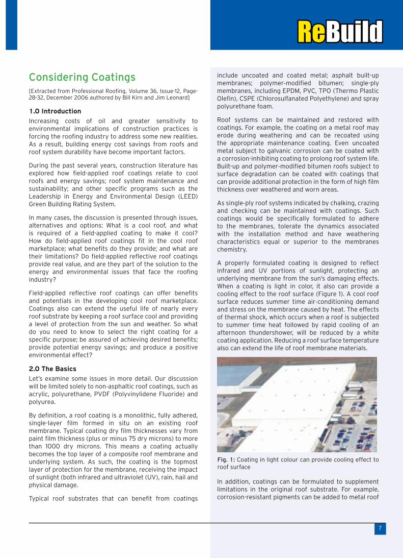
A properly formulated coating is designed to reflect infrared and UV portions of sunlight, protecting an underlying membrane from the sun’s damaging effects. When a coating is light in color, it also can provide a cooling effect to the roof surface (Figure 1). A cool roof surface reduces summer time air-conditioning demand and stress on the membrane caused by heat. The effects of thermal shock, which occurs when a roof is subjected to summer time heat followed by rapid cooling of an afternoon thundershower, will be reduced by a white coating application. Reducing a roof surface temperature also can extend the life of roof membrane materials.
In addition, coatings can be formulated to supplement limitations in the original roof substrate. For example, corrosion-resistant pigments can be added to metal roof
Fig. 1: Coating in light colour can provide cooling effect to roof surface

coatings and plasticizer-migration inhibitors can be added to coatings to reduce plasticizer loss from externally plasticized single-ply membranes. Additional features can be built into coatings to enhance a roof system’s fire-resistance rating and increase milddew and algae protection.
3.0 When to Coat
The appropriate time to coat a roof is while it still is possible for a coating to be most effective. Applying a coating early in a roof system’s life can help extend the performances of the desired properties originally built into the roof surface.
However, not all aged roofs are suitable for coating. If a metal roof is badly rusted in key areas or a roof membrane has failed at the seams, allowing significant water to be entrapped below the membrane, the prudent decision would be to tear off that section and replace it with new material before restoring the roof surface with field-applied coating. If a reinforcing mat or scrim in a single-ply membrane has deteriorated substantially because of excessive weathering or physical abuse, an unreinforced coating cannot be expected to have the tensile strength required to maintain the roof membrane’s integrity.
Similarly, if a glass mat or polyester mat of a conventional built-up or polymer-modified bitumen membrane roof system has deteriorated significantly, the roof may not be suitable for coating. Modern coatings without scrim reinforcement are not capable of providing the tensile strength typically provided by glass mats and polyester mats. However, if an existing roof membrane is mechani-cally and structurally viable and the roof system is dry, the roof would be considered a suitable candidate for coating and restoration.
4.0 Selecting a Coating
When selecting a coating, adhesion is the key property to consider. If a coating will not adhere to a roof substrate, none of the other properties matter and potential benefits of the coating will not be realized. Failure due to poor adhesion is shown in Figure 2.
8
Adhesion is best described as an interfacial property; that is, the quality of adhesion is defined as much by the coating or adhesive as it is by the roof substrate. Adhesion primarily depends on the chemistry of the coating and the substrate at that interfacial boundary. Dirt or any other foreign substance will interfere with the coating-substrate interaction.
For example, think about applying an epoxy adhesive to a Teflon frying pan. Chances are the adhesive will not adhere well. This is not because the adhesive is not “good” but because the chemistry of the substrate and chemistry of the adhesive (coating) are not suitable for or compatible with one another.
The same idea applies to roofs. Roof surfaces that initially are coated with silicone will require a silicone-compatible recoat. Likewise, fluoropolymer coatings require coatings composed of such resin or containing adhesion promoter chemistry to provide consistent adhesion.
Keep in mind factory-applied release agents, such as talc on EPDM and sand on polymer-modified bitumen, can interfere with adhesion. A coating may adhere to the talc or sand, but if the release agents are not embedded into the membrane, the coating may come loose with the talc or sand on the underside of the coating.
Adhesion of a coating to a roof substrate improves as the coating dries or cures (chemically reacts with moisture from the air). Depending on a coating’s chemistry, its cure time, dry time and skin time may be different. Some coatings, such as urethanes and silicones, not only must dry but also cure to achieve complete property development. Factors such as substrate temperature, air temperature and relative humidity will affect drying time and ultimate cure. Some coating manufacturers offer winter and summer “speed” coatings designed to skin and cure at appropriate rates based on weather conditions. Because coating adhesion is the key to a successful application, we recommend you always conduct a field adhesion test (Figure 3). We suggest a method similar to ASTM C794, “Standard Test Method for Adhesion-in-Peel of Elastomeric Joint Sealants”.
Fig. 2: Failure due to poor adhesion
Fig. 3: A field adhesion test as demonstrated in the figure helps to ensure a successful coating application

9
To use this method, brush a roof coating on a prepared roof surface and while the coating is wet, embed about 150 mm of a 25 by 300 mm cloth strip into the coating. Allow this to dry for a minimum of three days to four days (the longer the better). Then, attach a small fish scale (available at sporting goods stores) to the free end of the cloth strip and carefully cut the 25 mm wide sides of the strip, being careful not to cut into the underlying roof membrane substrate. Pull slowly on the fish scale, pulling the cloth strip away from the roof substrate. Read the weight (force) required as the cloth strip is pulled away.
ASTM International indicates 0.9 kg to 1.8 kg of pull is a satisfactory result. If some coating remains on the roof membrane as the strip is pulled, it indicates an even stronger cohesive failure (the coating is pulled apart) rather than adhesive failure of the coating to the substrate.
If wet adhesion properties are to be measured, follow the same procedure and after the test sample with fabric is fully cured, adhere a 50 mm sheet-metal cylinder with a 300 mm diameter to the roof substrate using caulk. Fill the cylinder with water and wait one week before conducting the pull test. Wet adhesion of a fully cured acrylic sample typically is half of dry adhesion values.
5.0 Maximize Adhesion
As mentioned earlier, dirt and other foreign substances can interfere with a coating’s adhesion. For proper adhesion, a roof substrate must be cleaned and prepared satisfactorily. Before performing the adhesion test, clean the roof surface to reflect the cleaning process that will be used across the entire field of the roof.
Most roof surfaces are best cleaned by power washing (Figure 4) at a pressure that considers the substrate conditions and properties. Heavily soiled surfaces may require a cleaner to be used to achieve satisfactory results. Cleaners may be biodegradable non-phosphate detergents for heavy dirt; phosphate cleaners may be required for certain oils and grease. Be sure to dilute acid cleaners for heavy rust on steel and bleach solution for heavy mildew/algae deposits.
After cleaning a roof surface, rinse it well to remove loose dirt, and if any cleaners are used, use copious amounts of water to remove all potential cleaner residues. Also, consider the potential environmental issues (with-out phosphates) with cleaners, and collect runoff residue whenever possible and if environmental regulations so require.
To determine whether a roof has been cleaned satisfac-torily, consider using this easy method: Once a roof has been cleaned and dried, press a 75 to 100 mm-long piece of 50 mm masking tape to the roof using hand pressure. Then, peel the tape off. If it comes off easily and/or is laden with dirt, degraded roofing material and other particulates, the roof is not cleaned satisfactorily. Reclean and dry the roof, and repeat the test. The test should be conducted in several areas around the roof, especially in ponded or other dirty areas.
If satisfactory adhesion of the coating to a clean roof surface cannot be achieved, consider using a primer to improve adhesion. But remember, a primer is not a replacement for thorough cleaning. A primer is designed to adhere to a structurally sound (dirt-free) substrate and provide a better surface to which the coating can adhere.
6.0 Applying the Coating
It is important to follow roof coating manufacturers’ directions and cautions when applying any roof coating. Typically, a manufacturer’s product data sheet will list the appropriate substrate and recommended film thickness for a particular coating on any specific roof substrate.
Reflective roof coatings typically will be applied by power spray or roller or combinations of spray and roll as determined by the coating’s thixotropy (resistance to sag and run) and roof’s surface texture and porosity. A highly thixotropic base coat applied to a rough roof surface may have to be rolled to force the coating into the low spots and maximize coating contact with the roof surface. The reflective finish coat then typically is sprayed, often in two passes, to provide the most uniform film thickness possible.
7.0 Energy Savings
It has become widely accepted in the roofing industry that field-applied white reflective coatings can lower roof surface temperature and provide energy savings while reducing maintenance costs and extending the life of the original roof surface.
Actual energy savings from a coating application depends on a myriad of factors, including difference in solar reflectance and emittance from original roof substrate to the coated surface; climate (tropical to arctic and rainfall levels); microclimate (dirt, surface contaminants,
Fig. 4: For proper adhesion, roof surface must be cleaned by power washing and prepared satisfactorily
10
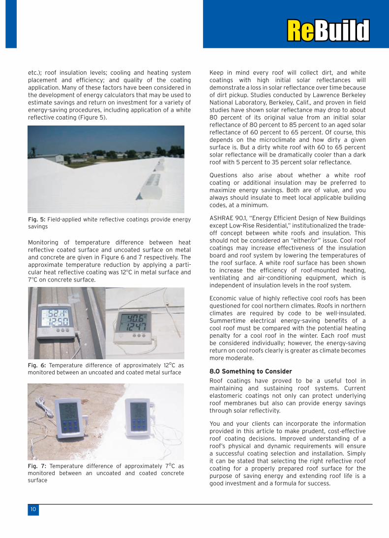
etc.); roof insulation levels; cooling and heating system placement and efficiency; and quality of the coating application. Many of these factors have been considered in the development of energy calculators that may be used to estimate savings and return on investment for a variety of energy-saving procedures, including application of a white reflective coating (Figure 5).
Monitoring of temperature difference between heat reflective coated surface and uncoated surface on metal and concrete are given in Figure 6 and 7 respectively. The approximate temperature reduction by applying a parti-cular heat reflective coating was 12oC in metal surface and 7oC on concrete surface.
Keep in mind every roof will collect dirt, and white coatings with high initial solar reflectances will demonstrate a loss in solar reflectance over time because of dirt pickup. Studies conducted by Lawrence Berkeley National Laboratory, Berkeley, Calif., and proven in field studies have shown solar reflectance may drop to about 80 percent of its original value from an initial solar reflectance of 80 percent to 85 percent to an aged solar reflectance of 60 percent to 65 percent. Of course, this depends on the microclimate and how dirty a given surface is. But a dirty white roof with 60 to 65 percent solar reflectance will be dramatically cooler than a dark roof with 5 percent to 35 percent solar reflectance.
Questions also arise about whether a white roof coating or additional insulation may be preferred to maximize energy savings. Both are of value, and you always should insulate to meet local applicable building codes, at a minimum.
ASHRAE 90.1, “Energy Efficient Design of New Buildings except Low-Rise Residential,” institutionalized the trade-off concept between white roofs and insulation. This should not be considered an “either/or” issue. Cool roof coatings may increase effectiveness of the insulation board and roof system by lowering the temperatures of the roof surface. A white roof surface has been shown to increase the efficiency of roof-mounted heating, ventilating and air-conditioning equipment, which is independent of insulation levels in the roof system.
Economic value of highly reflective cool roofs has been questioned for cool northern climates. Roofs in northern climates are required by code to be well-insulated. Summertime electrical energy-saving benefits of a cool roof must be compared with the potential heating penalty for a cool roof in the winter. Each roof must be considered individually; however, the energy-saving return on cool roofs clearly is greater as climate becomes more moderate.
8.0 Something to Consider
Roof coatings have proved to be a useful tool in maintaining and sustaining roof systems. Current elastomeric coatings not only can protect underlying roof membranes but also can provide energy savings through solar reflectivity.
You and your clients can incorporate the information provided in this article to make prudent, cost-effective roof coating decisions. Improved understanding of a roof’s physical and dynamic requirements will ensure a successful coating selection and installation. Simply it can be stated that selecting the right reflective roof coating for a properly prepared roof surface for the purpose of saving energy and extending roof life is a good investment and a formula for success.
Fig. 5: Field-applied white reflective coatings provide energy savings
Fig. 6: Temperature difference of approximately 12oC as monitored between an uncoated and coated metal surface
Fig. 7: Temperature difference of approximately 7oC as monitored between an uncoated and coated concrete surface

properly sleeved and waterproofed with flanged sleeves and collars.
Balustrade posts should be fixed to the face of the wall if possible (Figure 1). Where penetrations for balustrades are unavoidable, posts should be cored into the slab and the membrane turned up the post to at least 25 mm above the surface level of any finishes. The turned up membrane can then be concealed and protected from UV rays and mechanical damage by cover plates.
It is, however, often impractical to face fix or core balustrades into the slab and a baseplate system of fixing is required. In these instances an initial layer of membrane should be applied under the area of the baseplate and a second layer of membrane should later be installed over the baseplate and turned up the post to at least 25 mm above the surface level of any finishes. The turned up membrane can then be sealed with a cover plate. When the membrane is laid over a baseplate, any fixings should be countersunk.
Another aspect of design that is critical to the end performance of the waterproofing system is the detailing of the membrane at its perimeter, e.g. the detailing at its junction with any parapet wall, hob, building envelope and under any door and window sills.
The detailing of membrane to parapet wall junctions (Fig. 2) can be successfully achieved in a number of ways.
11
BEST PRACTICE GUIDELINES FOR EXTERNAL WATERPROOFING MEMBRANES [Extracted from Super Show 08, a publication jointly by Building and Construction Industry (BSA) Australia and Construction Skills Queensland (CSQ) Australia]
1.0 Introduction
Increasingly, Building and Construction Industry are receiving complaints about failed and leaking basements, retaining walls, balconies and planter boxes. The Building Code requires constructions to safeguard occupants from illness or injury and protect a building from damage caused by surface water, external moisture entering a building, and internal moisture accumlating in a building. Concerns raised about roof, deck and balcony membranes, by building industry contractors and professionals nationally, has prompted Standards Australia to begin producing two new standards, where previously no contemporary and comprehensive standard existed. These are AS 4654.1 (Waterproofing membrane systems for exterior use) and AS 4654.2 (Waterproofing membrane systems for exterior use above ground level).
The aim of the completed standards is to produce a consistent and reliable approach to the materials used in the design and installation of external waterproofing. Industry research and experience has found that the design of roofs, decks, balconies and planter boxes contributes to many of the failures of waterproofing systems. By setting an industry standard for materials, design and installation, the failure rate of external membranes is expected to dramatically reduce.
2.0 Roof, Podium Slabs and Concrete Balcony Slabs
A number of significantly defective roof and podium slabs have been brought to attention. These include: delamination of tiles from the membrane to which they were adhered; dissolution of the membrane which results in water penetration; breaks or tears in membranes and/or tiles caused by thermal or footing movement; and inadvertent penetration of the membrane after it has been applied (e.g. by the fixing of balustrade posts).
2.1 Design
Slabs should be laid with falls to drainage points. A minimum fall of between 1:80 and 1:100 is recommended for slabs in sheltered locations and falls of between 1:60 and 1:80 for slabs in exposed locations. This may vary however, dependant upon: the exposure conditions of the slab; the catchment area of the podium, balcony or roof falling to each drainage point; and the type of membrane being used.
Contractors should avoid penetrating slabs wherever possible, but where penetrations are essential they must be
Fig. 1: Ballustrade post support detail
Fig. 2: Upstand/parapet protection
Commonly they are capped by metal flashings. Best practice procedures dictate that these cappings should be sloped or fall to shed water and should be side fixed rather than fixed through the top of the flashing. It is also important that the membrane is turned up the wall and preferably terminated behind the flashing.
For higher parapet walls, the membrane and capping may not overlap, however, in these situations the membrane should terminate in a rebate or reglet and be appropriately sealed and capped to prevent moisture penetrating behind the membrane.
Membranes should extend fully over any perimeter hob and be dressed down its external face, fixed into a rebate or reglet, and finished with a sealed finishing strip.
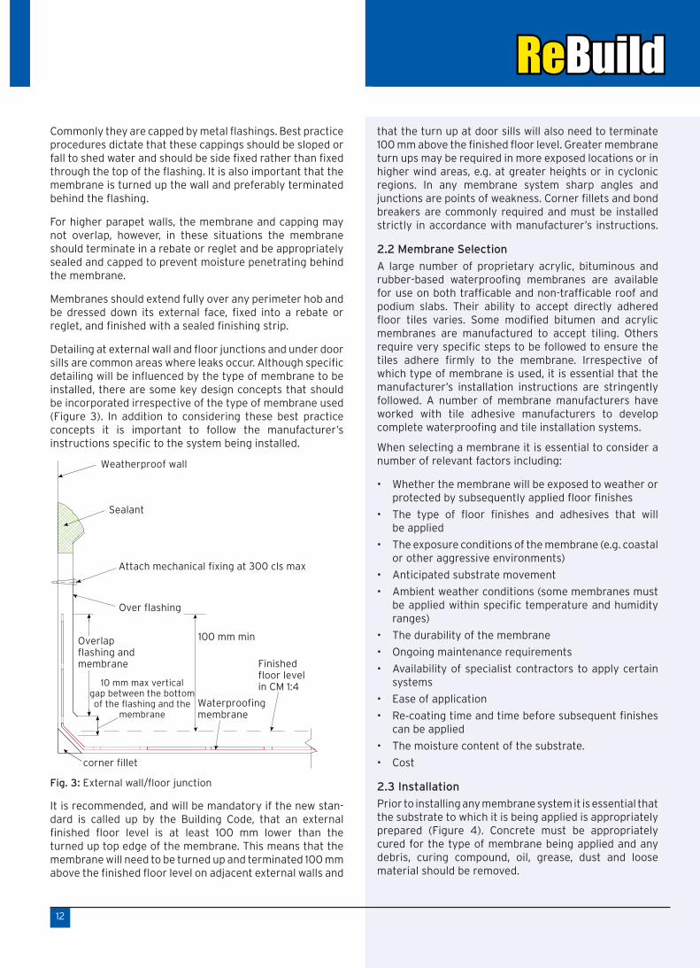
Detailing at external wall and floor junctions and under door sills are common areas where leaks occur. Although specific detailing will be influenced by the type of membrane to be installed, there are some key design concepts that should be incorporated irrespective of the type of membrane used (Figure 3). In addition to considering these best practice concepts it is important to follow the manufacturer’s instructions specific to the system being installed.
It is recommended, and will be mandatory if the new stan-dard is called up by the Building Code, that an external finished floor level is at least 100 mm lower than the turned up top edge of the membrane. This means that the membrane will need to be turned up and terminated 100 mm above the finished floor level on adjacent external walls and
that the turn up at door sills will also need to terminate 100 mm above the finished floor level. Greater membrane turn ups may be required in more exposed locations or in higher wind areas, e.g. at greater heights or in cyclonic regions. In any membrane system sharp angles and junctions are points of weakness. Corner fillets and bond breakers are commonly required and must be installed strictly in accordance with manufacturer’s instructions.
2.2 Membrane Selection
A large number of proprietary acrylic, bituminous and rubber-based waterproofing membranes are available for use on both trafficable and non-trafficable roof and podium slabs. Their ability to accept directly adhered floor tiles varies. Some modified bitumen and acrylic membranes are manufactured to accept tiling. Others require very specific steps to be followed to ensure the tiles adhere firmly to the membrane. Irrespective of which type of membrane is used, it is essential that the manufacturer’s installation instructions are stringently followed. A number of membrane manufacturers have worked with tile adhesive manufacturers to develop complete waterproofing and tile installation systems.
When selecting a membrane it is essential to consider a number of relevant factors including:
Whether the membrane will be exposed to weather or •protected by subsequently applied floor finishes
The type of floor finishes and adhesives that will •be applied
The exposure conditions of the membrane (e.g. coastal •or other aggressive environments)
Anticipated substrate movement•
Ambient weather conditions (some membranes must •be applied within specific temperature and humidity ranges)
The durability of the membrane•
Ongoing maintenance requirements•
Availability of specialist contractors to apply certain •systems
Ease of application•
Re• -coating time and time before subsequent finishes can be applied
The moisture content of the substrate.•
Cost•
2.3 Installation
Prior to installing any membrane system it is essential that the substrate to which it is being applied is appropriately prepared (Figure 4). Concrete must be appropriately cured for the type of membrane being applied and any debris, curing compound, oil, grease, dust and loose material should be removed.
12
Fig. 3: External wall/floor junction

Waterproof membranes rely on a complete system to ensure that the waterproofing of the roof or podium slab is not compromised. It is essential that the manufacturer’s instructions are meticulously followed and that:
Any depressions, joints or cracks are filled and sealed •as required
Any required reinforcing tape or bond breaker is applied •to joints and cracks
Any necessary suitable primer is applied (Figure 5)•
Specified coverage thickness is maintained for liquid •applied membrane
Re• -coating times are adhered as per specification
For preformed membrane, rolled out and •align the membrane over the primed surface (Figure 6)
Torch on the membrane under side with acetylene gas •to softening point (Figure 7) and press hard on to the surface
Keep overlap for minimum 100 mm (Figure 8)•
Finishing the joints with slight torching (Figure 9)•
Finishing up to parapet and seal the edges with •polysulphied sealant (Figure 10)
The application of screeds or other finishes is not •undertaken until the membrane has sufficiently cured
Membranes are appropriately protected from damage •until floor finishes are installed (Figure 11)
13
Fig. 4: Surface Preparation
Fig. 5: Primer application
Fig. 6: Rolling and aligning the membrane
Fig. 7: Torching of membrane and pressing
Fig. 8: Overlapping the membrane for minimum 100 mm
Fig. 9: Finishing at joints with slight torching

3.0 BASEMENTS AND RETAINING WALLS
Rectification of basement leaks is a particularly difficult and expensive task. The leak may be well underground, access around the building may not be possible, the perimeter of the building may be surrounded with pavements and landscaping and the basement may be fitted out for offices or other tenancies. Proper thought, good design, good installation practices and stringent supervision of the installation of waterproof membrane systems is essential to avoid these problems. An ideal basement detailing is given in Figure 12.
Traditional way of Basement waterproofing of SHAHBAD stone should be avoided because the joints of these stones need to be grouted properly otherwise leakage may occur through these joints. Also it is a labour intensive work for which it requires more time for installation.
Waterproofing membrane such as bituminous, polymer modified bituminous of APP (Atactic Poly Propylene) and SBS (Styrene Butadine Styrene), PVC, HDPE and EPDM are generally used for basements. Since APP membrane is torch applied, it requires more skilled labour and a protective screed to avoid any damages to the membrane. SBS is cold applied by simply sticking with a paste. But it is not suitable for high water table. It also requires a screed for protection. HDPE is the best material for waterproofing in high water table which is applied as loose lay. HDPE is also used on blind face of retaining wall. Bentonite is used for confined area of basement.
The primary components of any basement or retaining wall membrane system include:
The structural wall•
The waterproof membrane•
Protection of the membrane•
Drainage behind the wall, and•
Drainage at or near ground level•
In order to avoid some common causes of basement leaks it is recommended contractors pay particular attention to the following:
Ensure that a continuous membrane system is •installed under the slab and on the walls. If a different membrane is used under the slab and on the walls it is essential that a durable waterproof joint is provided at the junction of the two systems and that the two membranes are compatible.
Ensure that the external wall to floor junction is •appropriately designed, constructed and waterproofed.
Ensure membrane selection is appropriate and that •coverage is complete and of the required thickness. Use a vapour proof as well as a moisture proof membrane where the basement is used as a habitable space or for storage of sensitive equipment etc.
Use a membrane that is able to resist aggressive •chemicals or salts that may be present in the soil and is able to resist anticipated hydrostatic pressure.
Follow membrane manufacturer’s instructions exactly, •including issues like re-coating times.
Adequately prepare the substrate prior to application •of the membrane, including ensuring any concrete is appropriately cured.
Apply the membrane with the specified coverage and •thickness.
14
Fig. 10: Finishing at parapet
Fig. 11: Finishing with aluminium paint for non-foot traffic area and protective screed for foot traffic area
Fig. 12: Basement wall detail

Ensure that joints and penetrations are adequately •sealed.
Ensure the membrane is able to resist anticipated thermal •movement, soil movement or building settlement.
Install appropriate sub-soil and surface drainage •systems.
Avoid difficult joints and awkward shapes in basement •design that complicate the application of the membrane and have the potential to introduce ‘weak points’ in the system.
Adequately protect the membrane to prevent it from •being damaged by construction activities or backfilling.
4.0 PLANTER BOXES
Many of the principles discussed earlier also apply to planter boxes. However, planter boxes do have some additional specific requirements. An ideal plant box detailing is given in Figure 13.
The most significant of these is the necessity for adequate drainage. Planter boxes must have a graded base to the drainage outlet and the drainage system must prevent the water level from rising above the overflow level of the membrane. A filtered drainage riser must also be provided to relieve hydrostatic pressure, to provide access for cleaning, and as an emergency overflow in the case of excessive rain.
15
The membrane must be extended up the sides of the planter box to a minimum height of 100 mm above the soil level and must be protected with a drainage cell wrapped in geo-textile fabric or a similar suitable material.
The top edge of the membrane must be appropriately sealed and protected with either a flashing or capping tile or similar.
Care must be taken when selecting the type of plants to be grown in planter boxes. Those with aggressive root systems that may damage the membrane or clog the drainage system should be avoided. Trees or shrubs that grow and cause damage to the planter if they are blown over.
Finally, planter boxes require regular inspection and maintenance, perhaps more than any other membrane system. Building owners or their maintenance contractors need to regularly inspect and identify any damage or degradation caused by people, birds and other wildlife, pests, plant roots or general wear and tear. Prompt repair and maintenance should be undertaken based upon these inspections.
5.0 Roof Garden
Roof garden can be used for landscaping as well as vegetative roofing which is part of latest green roofing movement. But the waterproofing of the roof is more critical issue. An ideal detaining of waterproofing of roof garden is given in Figure 14.
Intensive green roofs utilize a wide variety of plant species that may include trees and shrubs which require deeper substrate layers (usually > 10 cm), and also require thicker membrane for waterproofing. In contrast, extensive roofs are limited to herbs, grasses, mosses, can be sustained in a shallow substrate layer (< 10 cm), require minimal maintenance, and a standard membrane. But the membrane should be non root penetrating one. Like planter box here the most significant issue is drainage. After installing the membrane a drainage board has to be installed over which a separation sheet of chip stand of geotextile mat of 225 GSM over the extruded polystyrene foam has to be provided. But the system requires periodical maintenance.
Fig. 14: Roof garden detail
Fig. 13: Planter box detail

Programmes Conducted
In• -house Training Programmes
Building Maintenance–Waterproofing and General Repair
Date : 20th & 21st January 2011
Protective Coatings for Durable Structures
Date : 18th March 2011
Attendees: RCF, IOCL (Delhi), HPCL, Mumbai Port Trust, TCE (Pune), SVNIT (Surat), Painterior, Maruti Group etc.
Corporate Training Programmes•
Building Maintenance-Waterproofing and General Repair
Date : 7th – 9th March and 21st and 23rd March 2011
Attendees : RCF Engineers
Venue : Mahul, Mumbai
College Level Training Programmes•
Professional Course in Structural Diagnosis and Repair of RC Structures
Date : 3rd January to 7th January 2011
Attendees : Third year Civil Engineering Students
Venue : MGM College of Engg. Kamothe, Navi Mumbai
The Institute’sActivities
Professional Course in Construction Chemicals – An Emerging Industry
Date : 10th January to 14th January 2011
Attendees : Final year Civil Engineering Students
Venue : MGM College of Engg. Kamothe, Navi Mumbai
Knowledge Awareness Sessions•
One special technical session conducted for the students of Construction Industry Staff College Hyderabad on 15th March 2011 on Durable Construction Practices
“Joints and Joint Treatments” and “Protective Coatings against Corrosion of Concrete structures”
Venue : ESCI (Engineering Staff College Institute), Hyderabad
Date : 9th February 2011
One awareness session organized for students of NICMAR, Hyderabad in the ACM course to introduce the elective course “Renovation of Buildings and Maintenance Management”.
Paper Presentation•Mr. E. Gopalakrishnan presented one paper “Advanced Repair Materials” in 2nd International Conference on Construction Chemicals held at Bangalore from March 17-18, 2011 organised by FICCI.
HCLS Programme•
Conducted two HCLS programmes with guest speaker Dr. Kriban G N, Managing Director – JTK Consult Sdn Bhd, Malayasia.
Topic : Advances in Waterproofing Materials and Technologies
Venue and Date : Hyderabad - 17th February 2011
Venue and Date : Mumbai - 18th February 2011
16
Participants in HCLS programme
Participants and Faculties in DFI training programme
Dr. Kriban delivering the lecture
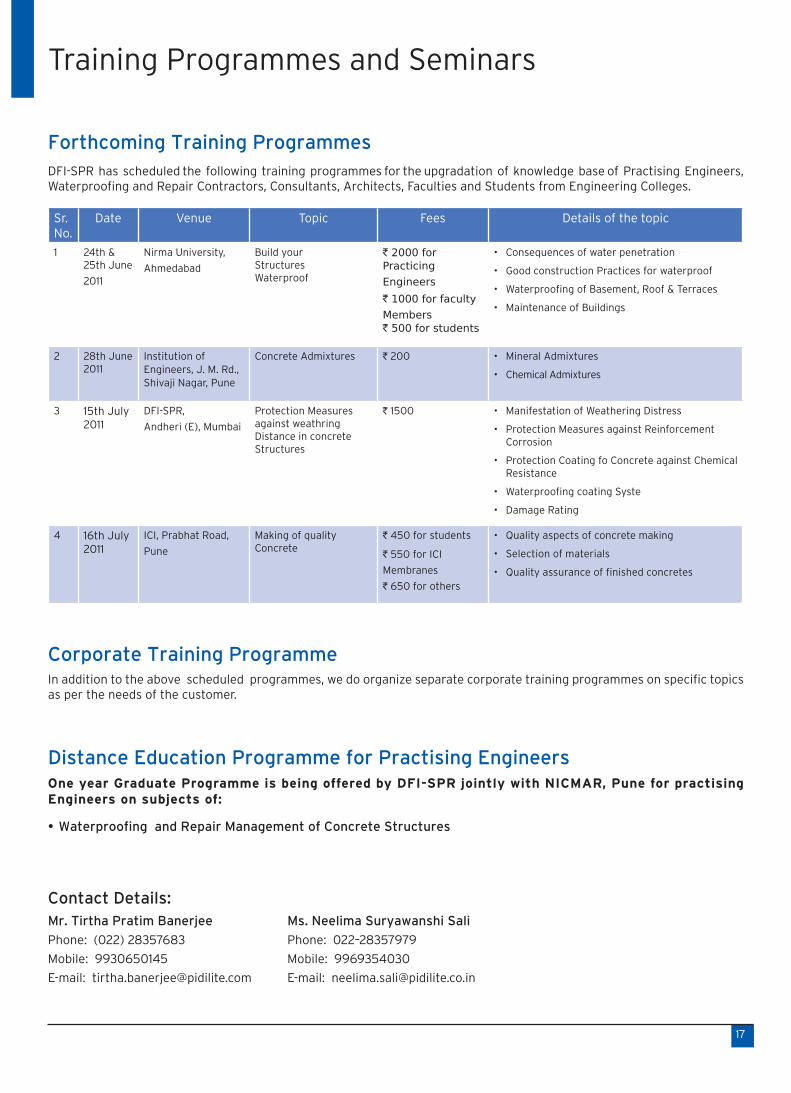
Forthcoming Training ProgrammesDFI-SPR has scheduled the following training programmes for the upgradation of knowledge base of Practising Engineers, Waterproofing and Repair Contractors, Consultants, Architects, Faculties and Students from Engineering Colleges.
Sr. No.
Date Venue Topic Fees Details of the topic
1 24th & 25th June
2011
Nirma University,
Ahmedabad
Build your Structures Waterproof
` 2000 for Practicing
Engineers
` 1000 for faculty
Members ` 500 for students
Consequences of water penetration•
Good construction Practices for waterproof•
Waterproofing of Basement, Roof & Terraces•
Maintenance of Buildings•
2 28th June 2011
Institution of Engineers, J. M. Rd., Shivaji Nagar, Pune
Concrete Admixtures ` 200 Mineral Admixtures•
Chemical Admixtures•
3 15th July 2011
DFI-SPR,
Andheri (E), Mumbai
Protection Measuresagainst weathring Distance in concreteStructures
` 1500 Manifestation of Weathering Distress•
Protection Measures against Reinforcement •Corrosion
Protection Coating fo Concrete against Chemical •Resistance
Waterproofing coating Syste•
Damage Rating•
4 16th July 2011
ICI, Prabhat Road,
Pune
Making of quality Concrete
` 450 for students
` 550 for ICI
Membranes
` 650 for others
Quality aspects of concrete making•
Selection of materials•
Quality assurance of finished concretes•
Corporate Training Programme In addition to the above scheduled programmes, we do organize separate corporate training programmes on specific topics as per the needs of the customer.
Distance Education Programme for Practising EngineersOne year Graduate Programme is being offered by DFI-SPR jointly with NICMAR, Pune for practising Engineers on subjects of:
Waterproofing and Repair Management of Concrete Structures•
Contact Details:Mr. Tirtha Pratim Banerjee Ms. Neelima Suryawanshi Sali
Phone: (022) 28357683 Phone: 022–28357979
Mobile: 9930650145 Mobile: 9969354030
E-mail: [email protected] E-mail: [email protected]
Training Programmes and Seminars
17

International Journal of 3R’s (Repair, Restoration and Renewal of Built Environment)
ISSN 0975-8968, Annual subscription: ` 1200` 1200`
Call for PapersPapers of scientific research, general discussion, case studies and point of view can be submitted through email to [email protected]@pidilite.co.in and [email protected] and [email protected] [email protected]. Also, papers can be submitted online on http://www.drfixitinstitute.com/articles/index.php.
Healthy Construction ManualsJoints & SealantsISBN: 978-81-909802-0-3, Price: ` 160Postage: ` 20 for Mumbai and` 20 for Mumbai and` ` 40 for outside` 40 for outside`
Publications
Published Articles
S.C.Pattanaik published a paper “Repair of Active Cracks of Concrete Structures with a Flexible Polyurethane Sealant for Controlled Movement” in conference proceedings in National Conference AMAS-2011, Feb 3-4, at Pondicherry Engineering College, Puducherry, and another paper “Self-Sealing Crystalline Coating and Self-Cleaning Nanocoating for the Concrete Substrate for a Sustainable Development” in the International Conference proceedings ICTACE 2011 held at Hyderabada, Feb 19 – 20.
Dr. A. K. Chatterjee has published articles “Waterproof your home” in Hindustan Times (htestates) dated 26th February 2011 and “Warning signs of water leakage” in DNA (Property) dated 5th March 2011 of Mumbai editions.
18
Prevent Leaks
HEALTHY CONSTRUCTION MANUAL - 2
Joints & sealants
(Published in Times property of The Times of India, Mumbai Edition dated 5th March 2011)(Published in Times property of The Times of India, Mumbai Edition dated 5th March 2011)
Dr. A. K. Chatterjee gives pointers on how to avoid seepage problems in your home along with remedial measures for the same

DFI-SPR
VISIONTo become a premier national knowledge and skill development centre for capacity enhancement in waterproofing and other areas of repair, restoration and renewal engineering based on sustainable and green technologies.
MISSIONTo act as a platform of national and international networking for sharing of knowledge and practices in the fields of waterproofing, repair, restoration, and renewal engineering in the context of life cycle assessment of the built environment for adoption of best practices by the country’s construction industry.
Editorial Advisor : Dr. A. K Chatterjee, Editorial Office : Mr. S. C. Pattanaik, Editor and Mr. C. H. PagePrinted & Published by Dr. Fixit Institute of Structural Protection & Rehabilitation, Ramkrishna Mandir Road, Post Box No.17411, Andheri (E), Mumbai 400 059 INDIA. Tel +91-22-28357149
DFI – SPR : ACTIVITY CHART
1919

Reader’s Feedback & Interaction SolicitedOur Newsletter is focused on good concreting practices, waterproofing, repair, rehabilitation and maintenance of concrete structures and buildings. Any reader, who wishes to contribute his or her experience or achievements in this field to our Newsletter for wider dissemination, may send the details to:
The Editor – ’Rebuild’Dr. Fixit Institute of Structural Protection & Rehabilitation
C/o Pidilite Industries Limited Ramkrishna Mandir Road, Andheri (E), Mumbai 400 059Tel : 022 – 2835 7973 / 2835 7149E-mail : [email protected] [email protected] us at : www.drfixitinstitute.com