adms-13 instruction manual
TRANSCRIPT

ADMS-13Instruction Manual
The ADMS-13 software provides convenient editing of the FTM-6000R/E memory channel frequencies, channel information and alpha tags, using a personal computer. Also the transceiver parameters and the setup menu items may be edited and configured easily from the computer keyboard.
YAESU MUSEN CO., LTD.

Introduction ........................................... 3About this manual ....................................... 3Important Notes ........................................... 3System Requirements ................................. 4
Supported Operating Systems ................... 4CPU ........................................................... 4RAM (System Memory) .............................. 4HDD (Hard Disk) ........................................ 4Cables ........................................................ 4Necessary PC peripheral interfaces .......... 4
The flow of a setup of ADMS-13 ................. 4Trademarks ................................................... 4
Setup of the ADMS-13 .......................... 5Preparation ................................................ 5ADMS-13 Programming Software Installation ... 5Unistalling the ADMS-13 ............................ 6SCU-20 USB Driver Software Installation ... 7Connect the FTM-6000R/E and the PC ..... 7
Execute the ADMS-13 ........................... 8Display examples ......................................... 8
First Screen ................................................ 8Menu Bar ................................................... 9TAB Menu Bar ............................................ 9Set mode screen ...................................... 10
Communications (Data communication with the FTM-6000R/E) ... 11
Communication port setting ...................... 11Get Data from FTM-6000 .......................... 11Send Data to FTM-6000 .......................... 12
Names and Functions of Menu Bar ... 13File ............................................................... 13
• New ............................................................... 13• Open .............................................................. 13• Close ............................................................. 13• Save .............................................................. 13• Save as ......................................................... 13• Import ............................................................ 13• Export ............................................................ 14• Print ............................................................... 14• Exit ................................................................ 14
Edit .............................................................. 15• Undo .............................................................. 15• Cut ................................................................. 15• Copy .............................................................. 15• Paste ............................................................. 15• Find ............................................................... 15• Find Next ....................................................... 15• Goto Channel ................................................ 16• Insert Channel ............................................... 16• Delete Channel .............................................. 16• Clear Channel ............................................... 16• Move Up ........................................................ 16
• Move Down ................................................... 16• Add Frequency Range .................................. 17• Sort ............................................................... 17
Communications (Data communication with the FTM-6000R/E) ... 18Settings ....................................................... 18
• Set Mode ....................................................... 18• Tool Bar ......................................................... 19• Status Bar ...................................................... 19
Window ....................................................... 19Setting the Template Items ................ 20
Memory ....................................................... 20Memories ................................................. 20PMS ......................................................... 20About the setting items of each memory channels ..... 20• Receive Frequency/ Transmit Frequency ...... 20• Offset Frequency ........................................... 20• Offset Direction .............................................. 20• Operating Mode ............................................. 20• TAG ............................................................... 21• Name ............................................................. 21• Tone Mode ..................................................... 21• CTCSS Frequency ........................................ 21• DCS Code ..................................................... 21• User CTCSS .................................................. 21• Tx Power ....................................................... 21• Step ............................................................... 21• Narrow ........................................................... 21• Clock Shift ..................................................... 21• Comment ....................................................... 21
VFO ............................................................. 22About the setting items of VFO frequencies .............. 22• Receive Frequency ....................................... 22• Transmit Frequency ...................................... 22• Offset Frequency ........................................... 22• Offset Direction .............................................. 22• Operating Mode ............................................. 22• Tone Mode ..................................................... 22• CTCSS Frequency ........................................ 22• DCS Code ..................................................... 22• User CTCSS .................................................. 23• Tx Power ....................................................... 23• Auto Step ....................................................... 23• Step ............................................................... 23• Narrow ........................................................... 23• Clock Shift ..................................................... 23• Comment ....................................................... 23
HOME .......................................................... 24About the setting items of HOME Bchannel frequency ... 24• Receive Frequency / Transmit Frequency ..... 24• Offset Frequency ........................................... 24• Offset Direction .............................................. 24
Table of contents
1

• Operating Mode ............................................. 24• TAG ............................................................... 24• Name ............................................................. 24• Tone Mode ..................................................... 24• CTCSS Frequency ........................................ 24• DCS Code ..................................................... 25• User CTCSS .................................................. 25• Tx Power ....................................................... 25• Step ............................................................... 25• Narrow ........................................................... 25• Clock Shift ..................................................... 25• Comment ....................................................... 25
Troubleshooting ................................. 26
2

IntroductionThe ADMS-13 programming software uses a Personal Computer to quickly enter and save the FTM-6000R/E memory channel frequencies and data. Also the many menu settings may be adapted for individual operating preferences. All of the information is saved. The setting data can be imported from the FTM-6000R/E and edited setting data can be transferred to the FTM-6000R/E.
Edit the frequencies, memory names, squelch settings, repeater settings, transmit power, etc. that is related to the VFO, memory channels, and the HOME channel, etc.
Configure the various set mode menu options on the computer monitor screen Use the handy editing functions, such as search, copy, move and paste
About this manualThis manual contains symbols and conventions to call attention to important information.Symbols Description
This icon indicates cautions and alerts the user should be aware of.
This icon indicates helpful notes, tips and information.
Important NotesBefore downloading this software, please read the “Important Notes” carefully.
• Copyrights and all other intellectual property rights for the software, as well as the soft-ware manual, are the property of YAESU MUSEN CO., LTD.
• The revision, modification, reverse engineering, and decompiling of this software is prohibited. Redistribution, transfer, and resale of downloaded files are also prohibited.
• Do not resell the software or manuals. • All responsibility for the use of this software lies with the customer. Yaesu cannot be
held responsible in any way for any damages or losses, which may be incurred by the customer as a result of using this software.
To use the ADMS-13 programmer, the software application must first be installed onto the computer. Read this manual thoroughly and install the software.
3

System RequirementsSupported Operating SystemsMicrosoft® Windows® 10 (32 bit/64 bit) Microsoft® Windows® 8.1 (32 bit/64 bit)
CPUThe performance of the CPU must satisfy the operating system requirements.
RAM (System Memory)The capacity of the RAM (system memory) must be more than sufficient to satisfy the operating system requirements.
HDD (Hard Disk)The capacity of the HDD must be more than sufficient to satisfy the operating system requirements.In addition to the memory space required to run the operating system, about 50 MB or more of additional memory space is required to run the program.
Cables• When using a USB port on the computer: the optional SCU-20 PC connection cable for USB
(The SCU-20 is included in the optional SCU-40 WIRES X Connection Cable Kit.)• When using a COM port connection: the optional CT-163 cables* When using the SCU-20 cable, be sure to install the designated driver before connecting the cable to
the computer.
Necessary PC peripheral interfacesUSB port (USB 1.1 / USB 2.0) or RS-232C interface (COM port)
The flow of a setup of ADMS-13The procedure when using ADMS-13 for the first time is as follows:
ADMS-13 Programming Software Installation (5 page)↓
SCU-20 USB Driver Software Installation (7 page)↓
Connect the FTM-6000R/E and the PC (7 page)↓
Execute the ADMS-13 (8 page)↓
To a explanation of operation of the ADMS-13 (8 page)
TrademarksMicrosoft®, Windows®, Windows® 8.1 and Windows® 10 are registered trademarks in the United States and other countries.
4

Setup of the ADMS-13The procedure to install the ADMS-13 on a Windows 10® (64 bit) computer is shown below for the purpose of explanation.
Preparation Please download the ADMS-13 software from the Yaesu Website for details (http://www.yaesu.com/). Download the ADMS-13 Programming Software to the same folder, and extract the downloaded zip file. Start up the computer as an “Administrator” user.
ADMS-13 Programming Software Installation1. Start up the computer as an “Administrator” user.2. Double-click the “setup.exe” in the same folder that
you have unzip the files.• When the “.NET Framework install” dialog box
opens, follow the on-screen instructions to install.
3. The dialog box, which is shown right, will open. Click the [Next] button.
4. Select the folder to install, then click the [Next] button.
5

5. Click the [Install] button.• When the [User Account Control] dialog box opens,
click the [Yes] button.
6. When the installation is finished, the dialog box shown right will open. Click the [Finish] button, to complete the installation of the software.
Unistalling the ADMS-13The procedure to uninstall the ADMS-13 on a Windows 10® (64 bit) computer is shown below for the pur-pose of explanation.1. Disconnect the USB Cable from the computer.2. Click the [Start] button and then click “Settings”.3. Click “Apps”.4. Select “FTM-6000 ADMS-13 EXP” and then click “Uninstall”.
• When the “User Account Control” dialog box opens, click the left mouse button on [Yes].• The uninstall of the software will start. The unistall procedure ends with this.
6

SCU-20 USB Driver Software InstallationDo not connect the transceiver to the computer via the SCU-20 PC Connection Cable until the driver installation process has been completed. Connecting the SCU-20 to the computer before installation has been completed may result in the wrong driver being installed, preventing proper operation.
Before using the SCU-20 PC connection cable, installation of the driver software for the SCU-20 is required. Download the driver software for the SCU-20 in advance.Download the designated driver software from the Yaesu website (http://www.yaesu.com/). Read the installation manual thoroughly and install the driver.
Connect the FTM-6000R/E and the PC1. Refer to the figure and connect the SCU-20 PC connection cable.
When using the CT-163 cable, connect the D-SUB connector to the COM port of the PC.
USB
DATA
SCU-20(Included in the optional SCU-40)
7

Execute the ADMS-13Double-click the “FTM-6000 ADMS-13 EXP” icon on the desktop of a computer.Click “Exit” in the “File” menu to close the ADMS-13.
First, use the “Get Data from FTM-6000” command (Page 9) to upload the setting data of the FTM-6000 to the ADMS-13 programmer.
Display examplesFirst ScreenThis is the first screen to be displayed when starting the ADMS-13 software.
8

Menu BarClick the left mouse button on each Menu in the Menu bar to settings the import/export of the data file, get data form FTM-6000R/E and send data to FTM-6000R/E.
For more details, see “Names and Functions of Menu Bar”.
TAB Menu BarClick the left mouse button on each TAB in the title bar (Memories, PMS, VFO, HOME) to display the frequency list of the desired memory channels, VFO and other preset transceiver settings.
For more details, see “Setting the Template Items”.
9

Set mode screenBasic setting items which are not related to memory channels can be configured from “Set Mode”.Click the left mouse button on “Settings” in the “Settings” menu to open the item “Set Mode” window.
For more details, see “Set Mode”.
10

11
Communications (Data communication with the FTM-6000R/E)
Communication port setting1. Connect the FTM-6000R/E to a computer (Refer to the
“Connect the FTM-6000R/E and the PC”).2. Execute the ADMS-13 (Refer to the “Execute the
ADMS-13”).3. From the menu bar, select “Communications” menu,
and then click on the “COM port Settings”.
4. Click [▼] in the “Serial Port Selection” column and click the COM port connected to the FTM-6000R/E.
5. Click [Determine].
Get Data from FTM-6000This command transfers the settings data of the FTM-6000R/E to the ADMS-13 programmer. To communicate with the FTM-6000R/E and create a new data file.1. Connect the PC connection cable SCU-20 between the FTM-6000R/E and the computer.2. Click the “ ” icon or the “Get Data from FTM-6000” parameter in the “Communications” menu.
The “Get Data From FTM-6000” window will open.3. Follow the on-screen instructions to acquire data from the FTM-6000R/E.
When the data transfer is completed, the template screen received from the FTM-6000R/E appears on the computer display.The memory channels and configuration menu data may be edited using the ADMS-13 software tools.

This template and configuration data may be saved to the computer hard drive, using the “Save” or “Save as” commands in the “File” menu.
Send Data to FTM-6000This command downloads the ADMS-13 data from the computer to the FTM-6000R/E.Click the “Save Data to FTM-6000R/E” parameter in the “Communications” menu. The transmission procedure screen will open.
To load a previously created data file to the FTM-6000R/E, click the “Open” parameter in the “File” menu, and open the desired file before performing the send data operation above.
1. Connect the PC connection cable SCU-20 between the FTM-6000R/E and the computer.2. Follow the on-screen instructions to transmit data to the FTM-6000R/E.
3. After the data transmission completes, “Completed” will appear on the computer display, and click the [Close] button.
4. The FTM-6000R/E will automatically re-start in accordance with the set data.
• Never disconnect the programming cable while data transmission is in progress.• Pay careful attention to the power cable and the connections to the FTM-6000R/E and the
computer, so as not to lose the power during data reception/transmission.
12

Names and Functions of Menu BarFile
• NewClick the “New” parameter in the “File” menu to open a new configuration file.Multiple configuration files may be created and opened at the same time.Standard values are preset for each memory channel, VFO and set mode.
• OpenClick the “Open” parameter in the “File” menu to display the “Open” window.Select the existing saved template file, and click the “Open” button.
• CloseClose the displayed configuration file by clicking the left mouse button on the “Close” parameter in the “File” menu.
• SaveClick the “Save” configuration in the “File” menu.To save the present configuration, and overwrite the selected configuration file without changing the file name.
• Save asClick the “Save As” parameter in the “File” menu.Specify the file name and destination folder for the selected configuration file and then click the “Save” button to save the file.
• ImportADMS-13 data files may be created using a spreadsheet such as Microsoft Excel.To create a data file for the import of data, save the spreadsheet in the “CSV” comma separated file format.A spreadsheet may be easily created by exporting the template data in the “CSV” format using the ADMS-13 “Export” command. After the “CSV” data has been edited the spreadsheet may be imported back into the ADMS-13 Programmer.A separate import file is needed for each template.For example, to import the VFO and memory templates; first, click the “VFO” tab to display the VFO template, then import the VFO (CSV) file; next, click the “Memories” tab to display the “Memory” template; then import the Memory (CSV) file.
Do not edit the “Check” line at the right side end of the completed CSV file.
13
• ExportTo export the data file in the “CSV” (Comma Separated Values) format.Click the “Export” parameter in the “File” menu, On the “Save as” screen displayed, specify the directory and file name and save the file.Type a file name in the bottom box, then click the [OK] button.
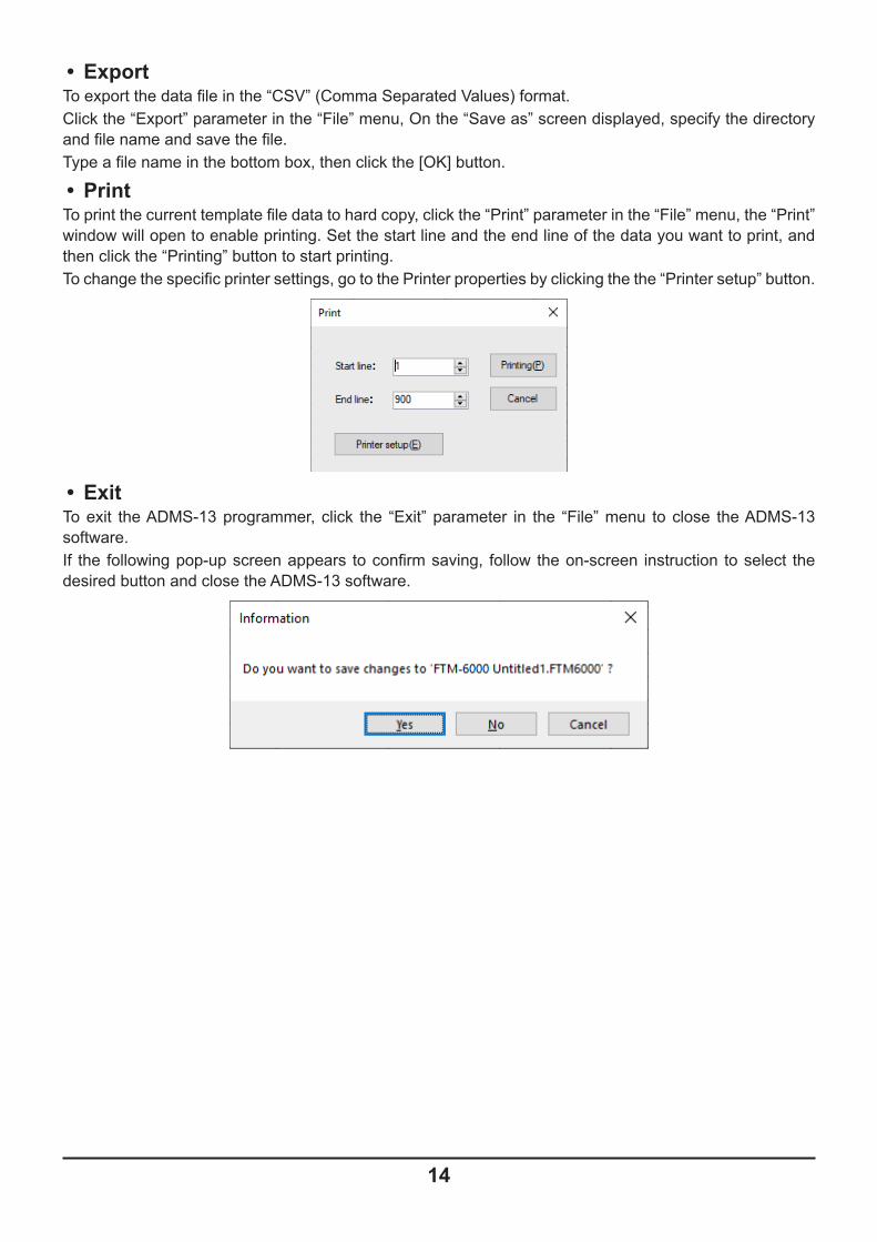
• PrintTo print the current template file data to hard copy, click the “Print” parameter in the “File” menu, the “Print” window will open to enable printing. Set the start line and the end line of the data you want to print, and then click the “Printing” button to start printing.To change the specific printer settings, go to the Printer properties by clicking the the “Printer setup” button.
• ExitTo exit the ADMS-13 programmer, click the “Exit” parameter in the “File” menu to close the ADMS-13 software.If the following pop-up screen appears to confirm saving, follow the on-screen instruction to select the desired button and close the ADMS-13 software.
14

EditClick the row to edit, then perform the following each operations.
Part of setting items of each row cannot be cut, copy, and paste is not possible.
• UndoTo undo the edited data, click the “Undo” parameter in the “Edit” menu.
• CutTo cut the data of the selected area, click the “Cut” parameter in the “Edit” menu.
• CopyTo copy the data of the selected area to the clipboard, click the “Copy” parameter in the “Edit” menu.
• PasteTo paste the clipboard data to the selected area, click the “Paste” parameter in the “Edit” menu.
• FindTo find a specified text, click the “Find” parameter in the “Edit” menu. The “Find” window will open.
Select the column from the drop down list. Enter the text to search for, and then click the [Find] button.The candidate character string found will be highlighted.
• Find NextClick the “Find Next” parameter in the “Edit” menu to move to the next candidate character string.
15

• Goto ChannelMove the cursor to the desired channel, click the “Goto Channel” parameter in the “Edit” menu to open the screen where you can specify the channel you want to move to.
Enter the channel number you wish to find, and then click the [Move] button.
• Insert ChannelTo insert channel data, click the “Insert Channel” parameter in the “Edit” menu to create a blank new channel data row under a current cursor. If there are any higher channel numbers with channel data, the higher channel numbers will be displayed after the newly inserted channel number so that the channels are displayed in the ascending order.Attempting to insert a new channel when highest channel contains data causes the data registered to highest channel to be deleted. “Continue?” will appear. If you agree, click the [OK] button.
• Delete ChannelTo delete the specified range of channel data, click the “Delete Channel” parameter in the “Edit” menu. The channels that were displayed after the deleted channels will shift up accordingly.
• Clear ChannelTo clear the current channel data, click the “Clear Channel” parameter in the “Edit” menu. The channels that were displayed after the deleted channels will not shift up and the blank channels will remain.
• Move UpTo move the current channel data up one row, click the “Move Up” parameter in the “Edit” menu.If other channel data already exists where the channel data moves, the existing channel will be overwritten.
• Move DownTo move the current channel data down one row, click the “Move Down” parameter in the “Edit” menu, the currently selected channel data moves downward one row.If other channel data already exists where the channel data moves, the existing channel will be overwritten.
16
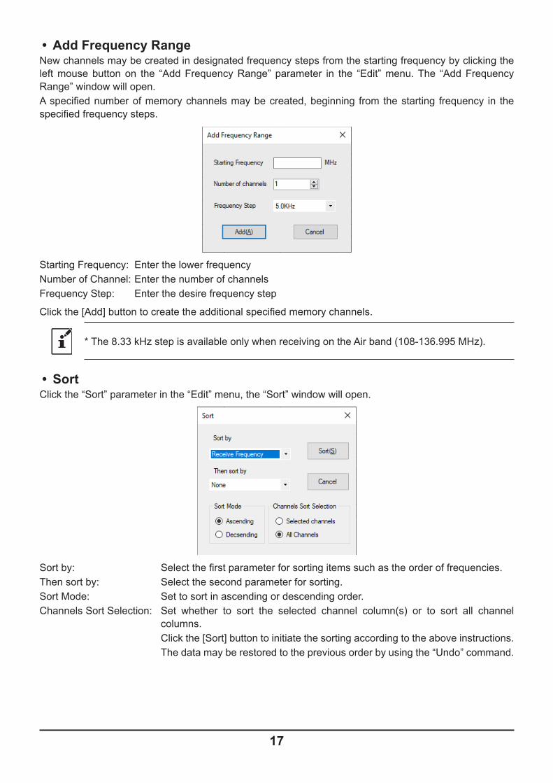
• Add Frequency RangeNew channels may be created in designated frequency steps from the starting frequency by clicking the left mouse button on the “Add Frequency Range” parameter in the “Edit” menu. The “Add Frequency Range” window will open.A specified number of memory channels may be created, beginning from the starting frequency in the specified frequency steps.
Starting Frequency: Enter the lower frequencyNumber of Channel: Enter the number of channelsFrequency Step: Enter the desire frequency step
Click the [Add] button to create the additional specified memory channels.
* The 8.33 kHz step is available only when receiving on the Air band (108-136.995 MHz).
• Sort Click the “Sort” parameter in the “Edit” menu, the “Sort” window will open.
Sort by: Select the first parameter for sorting items such as the order of frequencies.Then sort by: Select the second parameter for sorting.Sort Mode: Set to sort in ascending or descending order.Channels Sort Selection: Set whether to sort the selected channel column(s) or to sort all channel
columns. Click the [Sort] button to initiate the sorting according to the above instructions. The data may be restored to the previous order by using the “Undo” command.
17

Communications (Data communication with the FTM-6000R/E)
For details on the Communications Menu, refer to “Communications (Data communication with the FTM-6000R/E)” (Page 11).
Settings• Set ModeFrom the set mode menu, you can customize the various functions of the FTM-6000R/E according to your preferences.The ADMS-13 software displays the set mode menu in an easy-to-understand manner where you can change and save the setting values.Click the “Settings” parameter in the “Settings” menu to open the “SetMode” window.
To change the setting of each item in the window, click the “▼” icon to show the dropdown settings list, and then click the desired selection in the list.
18

Example:
Refer to the “FTM-6000R/E Operating Manual” for the details of each function.When you have completed editing the settings of the Menu Setting window.
• Tool BarClick the “Toolbar” parameter in the “Setting” menu to display or hide the Toolbar.A check mark appears next to the “Toolbar” parameter when the Toolbar is displayed.
• Status BarThe “Status Bar” describes the action to be executed by the selected menu item, or the depressed toolbar button, and keyboard latch state.A check mark appears next to the “Status Bar” parameter when the Status Bar is displayed.
WindowThis menu sets the operating window parameters of the ADMS-13 programmer.
• Click the “Tile (up and down)” parameter in the “Window” menu to display multiple template files by dividing the window into two lists (upper and lower parts).
• Click the “Tile (up and down)” parameter in the “Window” menu to display multiple template files by dividing the window into two lists (right and left parts).
• Click the “Cascade” parameter in the “Window” menu to display multiple templates in cascade format.
19
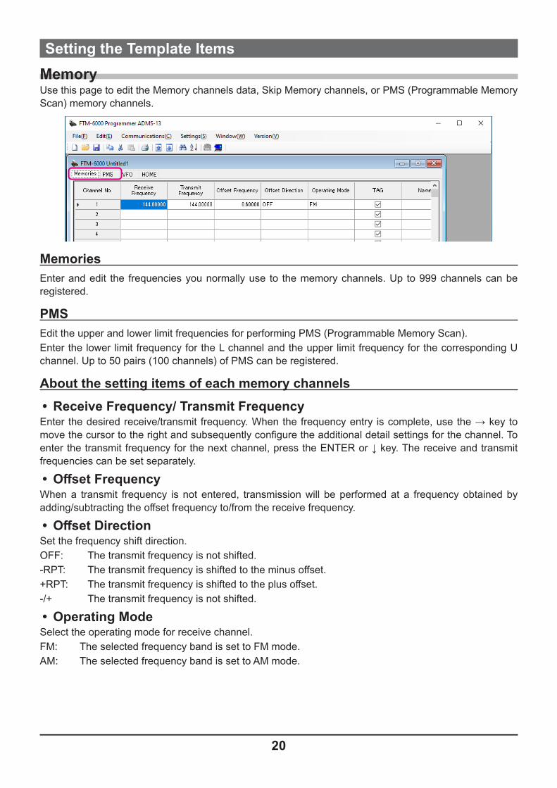
Setting the Template ItemsMemoryUse this page to edit the Memory channels data, Skip Memory channels, or PMS (Programmable Memory Scan) memory channels.
MemoriesEnter and edit the frequencies you normally use to the memory channels. Up to 999 channels can be registered.
PMSEdit the upper and lower limit frequencies for performing PMS (Programmable Memory Scan).Enter the lower limit frequency for the L channel and the upper limit frequency for the corresponding U channel. Up to 50 pairs (100 channels) of PMS can be registered.
About the setting items of each memory channels• Receive Frequency/ Transmit FrequencyEnter the desired receive/transmit frequency. When the frequency entry is complete, use the → key to move the cursor to the right and subsequently configure the additional detail settings for the channel. To enter the transmit frequency for the next channel, press the ENTER or ↓ key. The receive and transmit frequencies can be set separately.
• Offset FrequencyWhen a transmit frequency is not entered, transmission will be performed at a frequency obtained by adding/subtracting the offset frequency to/from the receive frequency.
• Offset DirectionSet the frequency shift direction.OFF: The transmit frequency is not shifted.-RPT: The transmit frequency is shifted to the minus offset.+RPT: The transmit frequency is shifted to the plus offset.-/+ The transmit frequency is not shifted.
• Operating ModeSelect the operating mode for receive channel.FM: The selected frequency band is set to FM mode.AM: The selected frequency band is set to AM mode.
20

• TAGBy ticking the checkbox of this item, when recalling the memory channels, the set memory tag and receive frequency are displayed. By Turning off the checkbox, the receive frequency is only displayed. This setting is common to all memory channels.
• NameEnter the desired memory name (up to 6 digits).
• Tone ModeThis item selects the Audio Squelch Code type.
• CTCSS FrequencyThis item selects the Tone Frequency of the Tone Squelch.
• DCS CodeSelect the DCS code when DCS is set.
• User CTCSSSelect the idle line frequency to remove signals such as idle line signals used by private railways and control signals of MCA radio system.
• Tx PowerThis item selects the TX Power.
• StepSets the channel step for receiving channels.
• NarrowBy ticking the checkbox of this item, switches to the Narrow FM mode.
• Clock ShiftWhen an internal spurious signal occurs due to the microcomputer clock, turn this setting on (tick the checkbox). This may improve the situation.Usually, this item is set to “OFF” (un-tick the checkbox).
• CommentComments may be added to the registered memory channels. Up to 255 letters can be used. This function is useful in organizing the memory channels by, for example, applying a category name to each channel.These comments are not transferred to the FTM-6000R/E.
21

VFOEdit the VFO configurations for each band on this page template.
About the setting items of VFO frequencies• Receive FrequencyEnter the VFO frequencies for each band. The FTM-6000R/E default Frequencies are pre-entered into the ADMS-13 standard template.A frequency that is out of the transceiver’s range cannot be entered. When the error pop-up window is opened, enter the correct frequency.
• Transmit FrequencyThe transmit frequency display is grayed out, and it will be set automatically, in accordance with the receive, and the offset frequencies.
• Offset FrequencyWhen a transmit frequency is not entered, transmission will be performed at a frequency obtained by adding/subtracting the offset frequency to/from the receive frequency.
• Offset DirectionSet the frequency shift direction.OFF: The transmit frequency is not shifted.-RPT: The transmit frequency is shifted to the minus offset.+RPT: The transmit frequency is shifted to the plus offset.
• Operating ModeSelect the operating mode for receive channel.FM: The selected frequency band is set to FM mode.AM: The selected frequency band is set to AM mode.
• Tone ModeThis item selects the Audio Squelch Code type.
• CTCSS FrequencyThis item selects the Tone Frequency of the Tone Squelch.
• DCS CodeSelect the DCS code when DCS is set.
22

• User CTCSSSelect the idle line frequency to remove signals such as idle line signals used by private railways and control signals of MCA radio system.
• Tx PowerThis item selects the TX Power.
• Auto StepBy ticking the checkbox of this item, the frequency step is set to “AUTO” automatically provides a suitable frequency step (frequency variation by rotating the DIAL knob) according to the frequency band. By Turning off the checkbox, the step setting become selectable.
• StepSets the channel step for receiving channels.
• NarrowBy ticking the checkbox of this item, switches to the Narrow FM mode.
• Clock ShiftWhen an internal spurious signal occurs due to the microcomputer clock, turn this setting on (tick the checkbox). This may improve the situation.Usually, this item is set to “OFF” (un-tick the checkbox).
• CommentComments may be added to the edited VFO bands. Up to 255 letters can be used. This function is useful in organizing the VFO bands by, for example, applying a category name to each VFO bands. These comments are not transferred to the FTM-6000R/E.
23

HOMEEdit the Home Channel configurations:
About the setting items of HOME Bchannel frequency• Receive Frequency / Transmit FrequencyEnter any desired changes into Home Channel frequency. The FTM-6000R/E default Frequencies are pre-entered into the ADMS-13 standard template.A frequency that is out of the transceiver’s range cannot be entered. When the error pop-up window is opened, enter the correct frequency. Inputting the receive frequency, the transmit frequency is automatically set.
• Offset FrequencyWhen a transmit frequency is not entered, transmission will be performed at a frequency obtained by adding/subtracting the offset frequency to/from the receive frequency.
• Offset DirectionSet the frequency shift direction.OFF: The transmit frequency is not shifted.-RPT: The transmit frequency is shifted to the minus offset.+RPT: The transmit frequency is shifted to the plus offset.-/+: The transmit frequency is not shifted.
• Operating ModeSelect the operating mode for receive channel.FM: The selected frequency band is set to FM mode.AM: The selected frequency band is set to AM mode.
• TAGBy ticking the checkbox of this item, when recalling the memory channels, the set memory tag and receive frequency are displayed. By Turning off the checkbox, the receive frequency is only displayed. This setting is common to all memory channels.
• NameEnter the desired memory name (up to 6 digits).
• Tone ModeThis item selects the Audio Squelch Code type.
• CTCSS FrequencyThis item selects the Tone Frequency of the Tone Squelch.
24

• DCS CodeSelect the DCS code when DCS is set.
• User CTCSSSelect the idle line frequency to remove signals such as idle line signals used by private railways and control signals of MCA radio system.
• Tx PowerThis item selects the TX Power.
• StepSets the channel step for receiving channels. Normally, when a frequency is entered, the optimal channel step will be automatically set according to the frequency.
• NarrowBy ticking the checkbox of this item, switches to the Narrow FM mode. The degree of modulation becomes half the normal level.
• Clock ShiftWhen an internal spurious signal occurs due to the microcomputer clock, turn this setting on (tick the checkbox). This may improve the situation.Usually, this item is set to “OFF” (un-tick the checkbox).
• CommentComments may be added to the edited HOME channels. Up to 255 letters can be used. This function is useful in organizing the HOME channels by, for example, applying a category name to each channel.These comments are not transferred to the FTM-6000R/E.
25

Troubleshooting• The FTM-6000R/E cannot receive or transmit data to the computer. The Data
transfer does not start.• Verify that the programming cable is correctly connected to the FTM-6000R/E data port and to the
Computer.Connect correctly.
• Is the computer COM Port setting correct?Set the COM Port correctly.
• Are you operating in a different order from the clicked the “Get Data from FTM-6000” in the “Communications” menu and displayed procedure? Follow the on-screen instructions.
• Are you operating in a different order from the clicked the “Send Data to FTM-6000” in the “Communications” menu and displayed procedure? Follow the on-screen instructions.
• The data transmission has stopped before completion• Disconnecting the connection cable or poor contact of the connection cable.
Confirm the cable connection and try again.
• The data import/export is not successful• Adjust the number of the rows of CSV file.• Use the designated letter for the character string.• When importing and exporting channels such as memory channels and VFO channels, make sure
that the template files are consistent. If the template files are different, an error will occur and the data import and export will not be successful.
26

2111-A
Copyright 2021YAESU MUSEN CO., LTD.All rights reserved.No portion of this manual may bereproduced without the permission ofYAESU MUSEN CO., LTD.
YAESU MUSEN CO., LTD.Tennozu Parkside Building2-5-8 Higashi-Shinagawa, Shinagawa-ku, Tokyo 140-0002 JapanYAESU USA6125 Phyllis Drive, Cypress, CA 90630, U.S.A.YAESU UKUnit 12, Sun Valley Business Park, Winnall CloseWinchester, Hampshire, SO23 0LB, U.K.