a versatile time-lapse camera system developed … versatile time-lapse camera system developed by ....
TRANSCRIPT

1
U.S. Department of the InteriorU.S. Geological Survey
Scientific Investigations Report 2008–5117
A Versatile Time-Lapse Camera System Developed by the Hawaiian Volcano Observatory for Use at Kïlauea Volcano, Hawaiÿi

This page left intentionally blank.

A Versatile Time-Lapse Camera System Developed by the Hawaiian Volcano Observatory for Use at Kïlauea Volcano, Hawaiÿi
By Tim R. Orr and Richard P. Hoblitt
Prepared in cooperation with the Bureau of Reclamation
Scientific Investigations Report 2008–5117
U.S. Department of the InteriorU.S. Geological Survey

ii
U.S. Department of the InteriorDIRK KEMPTHORNE, Secretary
U.S. Geological SurveyMark D. Myers, Director
U.S. Geological Survey, Reston, Virginia: 2008
This report and any updates to it are available online at: http://pubs.usgs.gov/sir/2008/5117/
For product and ordering information: World Wide Web: http://www.usgs.gov/pubprod Telephone: 1-888-ASK-USGS
For more information on the USGS — the Federal source for science about the Earth, its natural and living resources, natural hazards, and the environment: World Wide Web: http://www.usgs.gov Telephone: 1-888-ASK-USGS
Any use of trade, product, or firm names is for descriptive purposes only and does not imply endorsement by the U.S. Government.
Although this report is in the public domain, permission must be secured from the individual copyright owners to reproduce any copyrighted materials contained within this report.
Suggested citation:Orr, Tim R. and Hoblitt, Richard P., 2008, A versatile time-lapse camera system developed by the Hawaiian Volcano Observatory for use at Kïlauea Volcano, Hawaiÿi: U.S. Geological Survey Scientific Investigations Report 2008-5117, 8 p.
Cataloging-in-publication data are on file with the Library of Congress (http://www.loc.gov/).
Produced in the Western Region, Menlo Park, CaliforniaManuscript approved for publication, July 3, 2008Text edited by Tracey SuzukiLayout by David R. Jones

iii
Contents
Introduction.....................................................................................................................................................1
Previous Time-Lapse Camera Systems at Kïlauea ...................................................................................1Time-Lapse Camera System Components .................................................................................................1
Intervalometer .......................................................................................................................................2Digital Camera .......................................................................................................................................2Camera Enclosure.................................................................................................................................2
Device Power Requirements .......................................................................................................................4Power Options ................................................................................................................................................4
Internal Battery Without Solar Panel ................................................................................................4External Battery Without Solar Panel ...............................................................................................5Internal Battery With Solar Panel ......................................................................................................5External Battery With Solar Panel .....................................................................................................5
System Operation...........................................................................................................................................5Camera Settings ....................................................................................................................................6Intervalometer Settings .......................................................................................................................6Operating Procedure ............................................................................................................................6
Image Review .................................................................................................................................................7To the Future ...................................................................................................................................................7References Cited............................................................................................................................................8
Figures1. An example of a long-term time-lapse camera system deployment on the
steep flank of Pu‘u ÿÖÿö cone, Hawai‘i. ..................................................................................................12. The major components of the time-lapse camera system described in this report .......................23. Digital cameras used in the time-lapse camera systems deployed by the
Hawaiian Volcano Observatory. ..............................................................................................................24. This view of the hinge-side of the Pelican 1400 case. .........................................................................35. This view shows the screws protruding from the bottom of the Pelican 1400 case. .....................36. The ABS plate mounted inside the Pelican 1400 case. .......................................................................47. Basic wiring diagram for the time-lapse camera system. ..................................................................5

This page left intentionally blank.

A Versatile Time-Lapse Camera System Developed by the Hawaiian Volcano Observatory for Use at Kïlauea Volcano, Hawaiÿi
By Tim R. Orr and Richard P. Hoblitt
IntroductionVolcanoes can be difficult to study up close. Because it
may be days, weeks, or even years between important events, direct observation is often impractical. In addition, volcanoes are often inaccessible due to their remote location and (or) harsh environmental conditions. An eruption adds another level of complexity to what already may be a difficult and dangerous situation.
For these reasons, scientists at the U.S. Geological Survey (USGS) Hawaiian Volcano Observatory (HVO) have, for years, built camera systems to act as surrogate eyes. With the recent advances in digital-camera technology, these eyes are rapidly improving. One type of photographic monitoring involves the use of near-real-time network-enabled cameras installed at permanent sites (Hoblitt and others, in press). Time-lapse camera-systems, on the other hand, provide an inexpensive, easily transportable monitoring option that offers more versatility in site location. While time-lapse systems lack near-real-time capability, they provide higher image resolution and can be rapidly deployed in areas where the use of sophisticated telemetry required by the networked cameras systems is not practical.
This report describes the latest generation (as of 2008) time-lapse camera system used by HVO for photograph acquisition in remote and hazardous sites on Kïlauea Volcano.
Previous Time-Lapse Camera Systems at Kïlauea
Time-lapse camera systems were first employed by HVO in the early 1970s during the Mauna Ulu eruption on the upper east rift zone of Kïlauea. This system used Super 8 movie cameras with a time-lapse setting. The cameras were mounted inside surplus military ammunition boxes fitted with glass windows and attached to surveyor’s tripods. This system was used by HVO until 1997, when it was superseded by a telemetered volcano-imaging system installed at Pu‘u ÿÖÿö (Thornber, 1997).
Despite the success of the telemetered imaging system, these cameras were tethered by cables to telemetry/power sta-tions and, thus, were not portable. For this reason, retirement of the Super 8 time-lapse cameras effectively removed HVO’s portable time-lapse capability. The construction of the new time-lapse camera system described here (fig. 1), which takes advantage of the recent advances in digital-camera technol-ogy, was motivated by the desire to recover that portable time-lapse capability. Like the Super 8 system before it, this new system requires that the recording medium be changed regularly. However, unlike the Super 8 system which used film that required photo-lab developing, the digital camera in the new system uses CompactFlash memory cards, which can be downloaded and viewed using any modern computer.
Time-Lapse Camera System ComponentsThe major components of the camera system are shown
in figure 2. The intervalometer, which controls timing for the shutter release, was the component that made assembly of the time-lapse system possible. As the brain of the system, it was the first component that we selected. Because only one
Figure 1. An example of a long-term time-lapse camera system deployment, as described in this report, on the steep flank of Pu‘u ÿÖÿö cone, Hawai‘i.

2 A Versatile Time-Lapse Camera System for Use at Kïlauea Volcano, Hawaiÿi
type of intervalometer was available when we began to design the system, the camera choices were limited. The size of the camera selected was then used to determine the dimensions for the system enclosure. The individual system components are described below.
Intervalometer
The intervalometer used in this system is the Harbortron-ics Digisnap 2000 (fig. 2). This programmable device oper-ates with a wide variety of digital cameras, but it is designed around the Nikon COOLPIX camera series. The Digisnap controls many camera functions, but we have used it only to control the shutter release. The shutter release interval can be programmed to a maximum of 255 hours, 59 minutes, and 59 seconds. The minimum interval is limited only by the length of time required for the camera to write the previous picture to memory—nominally 15 seconds for a one-megapixel image.
The Digisnap is programmed by attaching a null-modem cable between a computer and the male DB-9 serial port on one side of the intervalometer. A terminal emulator program, such as HyperTerminal, bundled with the Microsoft Windows operating system, is used to configure the shutter release. Like-wise, to control a digital camera, a camera-specific serial cable attaches the Digisnap to the camera through the same port.
Digital Camera
As noted above, the Digisnap was designed especially for the Nikon COOLPIX series. After much testing, we settled
on the Nikon COOLPIX4300 and Nikon COOLPIX8700 as the preferred cameras within this series (fig. 3). Each camera offers distinct advantages, and both are interchangeable in our system. The salient features of each of these cameras are compared below:
Nikon COOLPIX4300 Nikon COOLPIX8700
4.0 megapixels 8.0 megapixels
3x optical zoom 8x optical zoom
CompactFlash card ≤ 2GB CompactFlash card > 2GB
Cost = ~$325 (new) Cost = ~$800 (new)
Although the number of megapixels and the increased zoom capacity make the COOLPIX8700 more versatile, we have rarely utilized these capabilities in our deployments. The main reason for using the COOLPIX8700 is that it uses the FAT32 file system. This is important because the Fat16 file system, used by the COOLPIX4300, limits its maximum effective storage to 2 GB, while a FAT32 partition does not have this limitation. Thus, while the Nikon 4300 can only use CompactFlash memory cards with a capacity of 2 GB or less, the Nikon 8700 can use CompactFlash cards with a capac-ity greater than 2 GB. One trade-off then, between these two cameras, is memory capacity versus cost.
Operationally, we have experienced numerous reliability problems with the Nikon COOLPIX8700 cameras. Each of the five COOLPIX8700 cameras that we have used in time-lapse deployments has failed at least once. In each failure, the symptoms have been the same: pronounced horizontal banding on the recorded images that makes them nearly unusable. This banding appears only during the daytime when the amount of available light is high. In low-light situations, the banding disappears, and the images look normal.
Camera Enclosure
Because of the extremely corrosive conditions typically found near active vents on Kïlauea, we selected a Pelican Products model 1400 environmental case (fig. 4). These rug-
A
C
B
D
E
F
G
A
C
B
D
E
F
G
Figure 2. The major components of the time-lapse camera system described in this report include the A, intervalometer, B, power inverter, C, 12-volt battery, D, waterproof enclosure, E, digital camera, F, charge controller for solar recharging deployments (optional), and G, solar panel (optional).
A BA B
Figure 3. Digital cameras used in the time-lapse camera systems deployed by the Hawaiian Volcano Observatory at Kïlauea Vol-cano, Hawai‘i. A, Nikon COOLPIX4300; B, Nikon COOLPIX8700.

Time-Lapse Camera System Components 3
ged cases, constructed of polyethylene, are weather-tight and impervious to acidic volcanic gases. The 1400 case is large enough to accommodate either model of COOLPIX camera described above and allows sufficient room for the other sys-tem components.
We customized the enclosure by cutting a 2-inch by 3-inch rectangular hole in the end of the case, with the long axis of the rectangle parallel to the case’s bottom. A 3⁄16-inch-thick piece of clear window glass is glued over the rectangular opening with silicone adhesive/sealant. Holes drilled in each corner of the glass with a diamond hole saw bit allow the window to be firmly attached to the enclosure with stainless steel machine screws (fig. 5). The window opening is centered on the camera lens.
Figure 4. This view of the hinge-side of the Pelican 1400 case shows the Conxall 2-pin, panel-mount receptacle connector used in the time-lapse camera system at Kïlauea Volcano, Hawai‘i.
Because of the difficulty of working with glass, we will likely explore other products for constructing windows for future enclosures. Lexan polycarbonate is the most obvious alternative. Although not as fragile as the window glass, it is softer and prone to being scratched when the window is cleaned.
Other external modifications include a rain/sun shield constructed from 3⁄16-inch-thick Acylonitrile Butadiene Styrene (ABS) plastic because it is easy to cut and easily welded using ABS cement. The shield is placed around the window opening and attached to the box using the same machine screws that hold the window glass in place (fig. 5). On the hinge side of the enclosure, adjacent to the window, a Conxall (Switchcraft, Inc.) two-pin, panel-mount receptacle connector (Conxall CXS3102A14S-9S-300) is installed (fig. 4) to attach an external power source. These small environmental connec-tors are pin-for-pin compatible with aluminum shelled, U.S. MIL-SPEC ones, but our experience has shown that the plastic construction of these Conxall connectors makes them more durable under the wet and corrosive conditions typically found near volcanic vents.
A mounting system for the external tripod bracket and internal camera/battery support plate is constructed by drill-
ing a hole through each of the four feet on the bottom of the Pelican case. A two-inch-long stainless steel machine screw, with the head cut off, is inserted through each hole (fig. 5). The screw length left exposed inside and outside the case should be the same. A dab of silicon sealant is applied to each machine screw at the hole, and stainless steel nuts are used on both the inside and the outside of the box to hold the machine screws in place. This allows the ABS sheet mounted inside the box (holding the camera, battery, and intervalometer) to be removed for maintenance without removing the external tripod mounting plate (both described below), and vice versa.
The internal camera mounting plate, with attached standoffs, is constructed from a 3⁄16-inch-thick ABS plastic
Figure 5. This view shows the screws protruding from the bottom of the Pelican 1400 case, which are used to attach the polyethyl-ene sheet that may be used to mount the camera enclosure on a standard surveyor’s tripod. The rain/sun shield and the window are attached over the window opening by using a single set of 4 stainless steel machine screws.
4 A Versatile Time-Lapse Camera System for Use at Kïlauea Volcano, Hawaiÿi
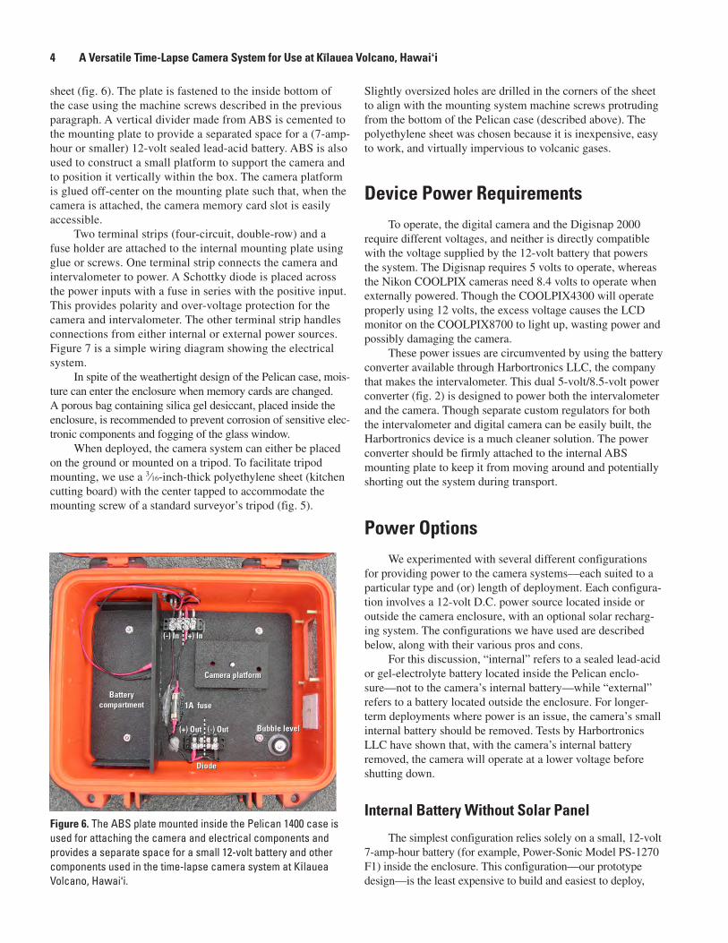
sheet (fig. 6). The plate is fastened to the inside bottom of the case using the machine screws described in the previous paragraph. A vertical divider made from ABS is cemented to the mounting plate to provide a separated space for a (7-amp-hour or smaller) 12-volt sealed lead-acid battery. ABS is also used to construct a small platform to support the camera and to position it vertically within the box. The camera platform is glued off-center on the mounting plate such that, when the camera is attached, the camera memory card slot is easily accessible.
Two terminal strips (four-circuit, double-row) and a fuse holder are attached to the internal mounting plate using glue or screws. One terminal strip connects the camera and intervalometer to power. A Schottky diode is placed across the power inputs with a fuse in series with the positive input. This provides polarity and over-voltage protection for the camera and intervalometer. The other terminal strip handles connections from either internal or external power sources. Figure 7 is a simple wiring diagram showing the electrical system.
In spite of the weathertight design of the Pelican case, mois-ture can enter the enclosure when memory cards are changed. A porous bag containing silica gel desiccant, placed inside the enclosure, is recommended to prevent corrosion of sensitive elec-tronic components and fogging of the glass window.
When deployed, the camera system can either be placed on the ground or mounted on a tripod. To facilitate tripod mounting, we use a 3⁄16-inch-thick polyethylene sheet (kitchen cutting board) with the center tapped to accommodate the mounting screw of a standard surveyor’s tripod (fig. 5).
Slightly oversized holes are drilled in the corners of the sheet to align with the mounting system machine screws protruding from the bottom of the Pelican case (described above). The polyethylene sheet was chosen because it is inexpensive, easy to work, and virtually impervious to volcanic gases.
Device Power RequirementsTo operate, the digital camera and the Digisnap 2000
require different voltages, and neither is directly compatible with the voltage supplied by the 12-volt battery that powers the system. The Digisnap requires 5 volts to operate, whereas the Nikon COOLPIX cameras need 8.4 volts to operate when externally powered. Though the COOLPIX4300 will operate properly using 12 volts, the excess voltage causes the LCD monitor on the COOLPIX8700 to light up, wasting power and possibly damaging the camera.
These power issues are circumvented by using the battery converter available through Harbortronics LLC, the company that makes the intervalometer. This dual 5-volt/8.5-volt power converter (fig. 2) is designed to power both the intervalometer and the camera. Though separate custom regulators for both the intervalometer and digital camera can be easily built, the Harbortronics device is a much cleaner solution. The power converter should be firmly attached to the internal ABS mounting plate to keep it from moving around and potentially shorting out the system during transport.
Power OptionsWe experimented with several different configurations
for providing power to the camera systems—each suited to a particular type and (or) length of deployment. Each configura-tion involves a 12-volt D.C. power source located inside or outside the camera enclosure, with an optional solar recharg-ing system. The configurations we have used are described below, along with their various pros and cons.
For this discussion, “internal” refers to a sealed lead-acid or gel-electrolyte battery located inside the Pelican enclo-sure—not to the camera’s internal battery—while “external” refers to a battery located outside the enclosure. For longer-term deployments where power is an issue, the camera’s small internal battery should be removed. Tests by Harbortronics LLC have shown that, with the camera’s internal battery removed, the camera will operate at a lower voltage before shutting down.
Internal Battery Without Solar Panel
The simplest configuration relies solely on a small, 12-volt 7-amp-hour battery (for example, Power-Sonic Model PS-1270 F1) inside the enclosure. This configuration—our prototype design—is the least expensive to build and easiest to deploy,
Camera platform
Bubble level
Diode
1A fuseBattery
compartment
(+) In(-) In
(-) Out(+) Out
Camera platform
Bubble level
Diode
1A fuseBattery
compartment
(+) In(-) In
(-) Out(+) Out
Figure 6. The ABS plate mounted inside the Pelican 1400 case is used for attaching the camera and electrical components and provides a separate space for a small 12-volt battery and other components used in the time-lapse camera system at Kïlauea Volcano, Hawai‘i.

System Operation 5
requiring only the camera enclosure with or without a tripod. The disadvantage of this configuration is that the system will operate only for a few days to perhaps a few weeks, depend-ing on the image-acquisition interval, before the battery is exhausted. The image frequency must be adjusted carefully to allow the system to run throughout the desired interval, and if continued operation is desired, the battery must be exchanged with a fully-charged battery before this interval expires.
If the battery does become exhausted, the camera and inter-valometer shut down, and no damage to the system is incurred. Images saved to the camera’s memory card are not lost.
External Battery Without Solar Panel
In many circumstances, the operational duration of the internal battery is inadequate. One simple solution to this problem is to use a much larger external battery. The external power connector on the enclosure allows the attachment of a deep-cycle, high-capacity, 12-volt storage battery (for exam-ple, ACDelco M27MF). With this configuration, again depend-ing on the image interval, the system can last for weeks, or even months, before the battery must be replaced. An example of this configuration is shown in figure 1.
Internal Battery With Solar Panel
In this configuration, a small solar panel (for example, BP Solar BPSX5M 5W/12V solar module) is mounted on the lid of the camera enclosure. The 5-watt solar-panel cable is threaded through a hole drilled through the back edge of the enclosure lid and attached to a small charge controller (for example, Morningstar SunGuard 4.5A 12V solar controller) inside the enclosure. The charge controller is then attached to the internal battery. The hole drilled for the solar-panel cable is sealed with silicone adhesive.
This configuration is compact, easily deployed, and has a longer operational time than an internal battery alone. For long-term deployments, especially when the image acquisi-tion interval was set to about 10 minutes or more, the bat-teries could recharge, and the system was able to run almost indefinitely. For short-term deployments with a short image-acquisition interval, the solar panel, while not keeping up with the total power demand of the system, prolonged functional operation of the system.
External Battery With Solar Panel
This is the best solution for long-term, or open-ended, deployments. In this configuration, a larger solar panel (for example, BP Solar BPSX30 30W/12V solar module), with a higher rated charge controller (for example, Morningstar SunSaver-10 10A 12V solar controller), is connected to an external high-capacity 12-volt storage battery (for example, ACDelco M27MF). The battery is then connected to the external power connector on the enclosure (fig. 4). The solar panel can be attached to the tripod, mounted to a simple solar-panel rack, or simply placed upon the ground.
At HVO, this configuration provides ample power to run reliable, long-term deployments with a high image-acquisition frequency. Thus, the capacity of the memory card, rather than the capacity of the battery, dictates when the camera site must be revisited.
System OperationThrough numerous tests and deployments, a general oper-
ating procedure was developed to allow anyone to success-fully deploy a time-lapse camera system and avoid a number of potential pitfalls. Still, it is important that every system be
+
-
+
-
2A fuse
12V
12V
20V/3A diodePower
inverter
Camera
Intervalometer
5V
8.5V
Figure 7. Basic wiring diagram for the time-lapse camera system, excluding the optional solar module charge controller, Kïlauea Volcano, Hawai‘i. The two 12-volt batteries are not intended to be run simultaneously, but they illustrate the two power options available—one for a battery inside the enclosure, the other for a battery external to the enclosure.

6 A Versatile Time-Lapse Camera System for Use at Kïlauea Volcano, Hawaiÿi
tested with the intended settings by letting it run for at least a week before field deployment. Some problems may not appear until several days have passed. Typical device settings and the general operating procedure are described below.
Camera Settings
The camera’s internal clock battery, which is different from the battery that operates the camera’s functions, takes about 10 hours to charge. It will hold a charge for several days when the camera is not attached to some other power supply. If this battery becomes exhausted, the camera will revert to its default settings, including default date and time. Checking the camera a day or two before the system is deployed is strongly recommended. If necessary, a power supply can be attached to the camera to recharge the clock battery. Take the camera’s manual into the field just in case the camera gets reset or other settings need to be changed.
There are several typical camera settings that we have used for time-lapse setups that are observing distant objects, both day and night. These settings include the following:
Confirm that the shooting mode is set to auto.•
Set the focus to infinity.•
Turn the flash off (this is the default when the camera is •set to infinity).
Set the desired image quality and image size.•
Disable the shutter sound to save power.•
Disable the shot confirmation lamp to save power.•
Set the camera’s “auto off” feature to the maximum •limit (it is uncertain if this really matters).
The camera settings for image quality and image size play an important role in every time-lapse deployment. No specific settings can be recommended as these are entirely dependent on the desired image resolution, the image-acquisi-tion interval, the length of the deployment, the power avail-able, and the capacity of the memory card. In general, how-ever, some quick testing suggests that sacrificing image size is preferable to sacrificing image quality.
The Nikon COOLPIX manuals, as do most digital-camera manuals, include an image quality versus image size grid. This is useful for estimating the number of images a memory card of a specified size can hold. The information presented in these grids, however, is based on memory cards much smaller than those used in typical time-lapse deploy-ments. For example, a typical deployment with a Nikon COOLPIX4300 might use an image quality of “Normal” and an image size of “1280 × 960.” The manual suggests that, with these settings, a 128 MB CompactFlash card will hold 381 pictures. Multiplying this number of pictures by sixteen
(128 MB × 16 = 2 GB) will provide a quick estimate of how many pictures will fit on a 2 GB card (6,096 pictures). The same procedure can be applied to the Nikon COOLPIX8700 to calculate the number of pictures that can be written to the larger-sized CompactFlash cards.
Intervalometer Settings
Using HyperTerminal or another terminal emulator, attach the intervalometer to the serial communication port on a computer with a null modem cable. The communication con-figuration is specified in the intervalometer manual. Turning on the intervalometer initiates communication with Hyper-Terminal, and the main Digisnap programming menu appears. Each of the intervalometer menus and options is discussed in detail in the manual.
For our deployments, we have only run the Digisnap in simple time-lapse mode. This mode specifies a fixed time-lapse interval. The Digisnap also has an advanced time-lapse mode that runs variable acquisition intervals that repeat each day.
Another basic setting for the Digisnap is the proto-col setting, which determines what functions are available to the camera. For an intervalometer attached to a Nikon COOLPIX4300 camera, the best performance was achieved with the “minimum protocol” setting. For the Nikon COOLPIX8700 camera, however, the best performance and power savings were achieved when using the “extended proto-col” setting.
In addition, the “camera check period” constant, found in the operation menu, should be set to 0 for the Nikon COOLPIX8700. The camera-check period determines how frequently the Digisnap will poll the camera to see if it is still connected. For the Nikon COOLPIX4300, the default period is adequate. The default values for the other constants in the operation menu can be used for both cameras.
Operating Procedure
The basic steps to start the time-lapse process are to (1) turn on the camera, (2) plug in the serial cable that attaches the intervalometer to the camera, and (3) start the intervalometer.
(1) Turn on the camera:
Remove the lens cap and turn on the camera. Watch to •see that the camera lens extends.
Check the camera’s LCD monitor to make sure the •desired settings appear. If you have to readjust the set-tings, also check the camera time—the clock battery may have discharged and reset the camera to default settings (see the discussion above).
Adjust the orientation of the camera box and zoom the •camera to frame the view you want. The LCD screen of both cameras is visible when either one is mounted

To the Future 7
in the enclosure. The only accurately repeatable zoom settings are either all the way in or all the way out.
(2) Attach the intervalometer to the camera:Attach the intervalometer to the camera with the serial •cable. This cable has a DB9 connector on one end and a Nikon mini-USB connector on the other. The camera’s LCD monitor should go blank when the cable is attached.
(3) Start the intervalometer:Watching the LED on the intervalometer, press any but-•ton on the device to wake it up. The LED will imme-diately flash yellow once as the Digisnap begins to establish communication with the camera.
Listen and watch closely. The camera will make some •clicking noises as the intervalometer communicates with it, and the camera will take a picture. This process takes about 20 seconds; the LED will periodically flash green during this period. If the LED flashes red, some-thing is wrong. Turn off the camera, cycle the power by removing and replacing the fuse or power supply, and try again.
Continue to watch the LED. After the first picture has •snapped, the LED will begin to blink green with a four-second interval indicating that the intervalometer is functioning properly in simple time-lapse mode. The green flashes can be subtle in bright light, so look closely. The chosen time-lapse interval begins when the first picture is taken.
Image ReviewBecause the camera systems described here are not
telemetered, it is necessary to exchange used CompactFlash memory cards with blank ones and to download the images from the cards manually. However, because the images are in a digital format, they can be readily reviewed and studied.
The Nikon COOLPIX cameras assign alphanumeric names to image files and place them in folders on the memory cards. We have found it useful to have the file name for the images correspond to the date and time at which the photo was taken. A typical deployment might produce thousands of photos in dozens of folders, and moving and renaming these images manually is too time-consuming. To streamline the process, we created a simple Windows XP batch file that renames the images to the date and time they were taken (based on the information stored in each image’s EXIF tags), extracts the image files from the downloaded folders, and deletes the subsequently empty folders. Photos are renamed to the date and time of acquisition through a call in the batch file to Jhead.exe, a command-line executable
that manipulates EXIF data. Jhead.exe is freeware and can be downloaded from numerous internet sites.
The images collected may be viewed as static images, or as animation sequences. We typically review each download of images as an animation sequence and tabulate interesting phenomena. This only takes a few tens of min-utes for a typical set of images captured during a period of a few weeks with an acquisition interval of 5 minutes. When something unusually interesting or exciting is encountered, the pertinent sequence of images is clipped out and con-verted into a short movie.
With time, the internal clock for the Nikon digital cameras drifts, and thus assigns incorrect times to images. To correct for the drift, we periodically hold a GPS unit showing the correct time in front of the time-lapse camera to capture images showing the correct time. By comparing a picture showing the actual GPS time to the time imprinted in the picture’s EXIF data, we can calculate clock drift. Simple EXIF data manipulation programs, such as EXIF Date Changer, are freely available on the Internet and can be used to adjust the EXIF time for all the images in a particular sequence for which the incorrect time applies. To minimize time offsets due to clock drift, the camera’s clock should be reset frequently. In Hawai‘i, where ambient temperature variations that cause camera-clock drift are minimal, we typically experience drift of only a few seconds per month.
To the FutureThe time-lapse camera systems described above have
proven invaluable. The systems have provided scientists at the Hawaiian Volcano Observatory with an exciting new way to record and study numerous volcanic phenomena—some of which have never before been observed, much less recorded—in unprecedented detail. Many particularly interesting sequences have been posted to the Hawaiian Volcano Observa-tory Web site and are viewable as time-lapse movies (http://hvo.wr.usgs.gov/gallery/kilauea/volcanomovies/, last accessed June 25, 2008).
The rapid pace of progress has already outrun the technology described here. The Harbortronics intervalometer requires a serial communication port. Although the Nikon COOLPIX series cameras described above have a dual USB/serial communication capability, the newest models only allow USB communication. For these newer cameras, the Harbortronics intervalometer will not work. Until another solution arrives, we must purchase older, used cameras as the current time-lapse systems wear out. Fortunately, internet reseller sites that commonly offer new or lightly used cam-eras will likely extend the useful operational life of systems built on the components described here for at least the next couple of years.

8 A Versatile Time-Lapse Camera System for Use at Kïlauea Volcano, Hawaiÿi
References Cited
Thornber, C.R., 1997, HVO/RVTS-1; a prototype remote video telemetry system for monitoring the Kīlauea east rift zone eruption, 1997: U.S. Geological Survey Open-File Report 97-0537, 18 p. [http://hvo.wr.usgs.gov/products/OF97537/contents.html, (last accessed June 25, 2008)].
Hoblitt, R.P., Orr, T.R., Castella, Frederic, and Cervelli, P.F., in press, Remote-controlled pan, tilt, zoom cameras at Kīlauea and Mauna Loa volcanoes, Hawai‘i: U.S. Geologi-cal Survey Scientific Investigations Report 2008-5129.

This page left intentionally blank.

To the Future 10
Orr and Hoblitt—A
Versatile Time-Lapse Cam
era System D
eveloped by the Haw
aiian Volcano Observatory for
Use at Kïlauea Volcano, H
awaiÿi—
Scientific Investigations Report 2008–5117