a installation of the machine -...
TRANSCRIPT

A1
E-Doku.Ser.No.:Fabr.No.:Baujahr / Year of constr.:Made by EMCO MAIER Ges.m.b.H.,Hallein/AUSTRIA
HYPERTURN 453×400V/PE 50/60 HzImax=43 A Ik<=10 kAeffSicherung der ZuleitungFuse for the supply line 50A gG, gL
S3A V01 BAS3A G03 122009
2
1
A Installation of the machine
Machine number (1) and electrical number (2)
Machine acceptanceCheck the machine for any transport damage and completeness of the delivery.If you find any defects, please contact the dealer or the insurance company.
In case of complaints always specify the exact designation of the machine and the machine number and the electric number.
Machine number and electrical numberThe type plate with the machine number (1) and the electrical number (2) on it is at the side of the machine, below the lockable main switch.In addition, the machine number is punched in the machine bed.
Note:The wiring diagrams valid for your machine are to be found in the electrical doc umen-tation which is in the switch cabinet of the machine. An electrical documentation can also be ob-tained by indicating the version number from EMCO:Sinumerik 840Dsl ....................ZVP 677 956Fanuc 18i .................................ZVP 677 957

A2
instAllAtionmAChine ACCeptAnCe
System Module-codeVersionsstamp/date
07.04.25-NCU572E 9001.34.07H0 kmpmain......00000000000000000
Monitor Loader .......................................................................................... Communic. Monitor ...................................................................................Communic. System ...................................................................................SIMATIC System ................................................................................................................................................................................................................................. .................................................................................................................. ............................................................................................................................................................................................................................................................................................................................
Versionsdata NCU
↓
1
Call-up of the Siemens NC-software number
File
Versionsdata MMC
Version sizedate
mmc0.exe 28.09.09 162 13324.Sep.2009
File ................... ................................File ....... ........... ................................File ................... ................................File ......... ......... ................................File ................... ................................File .......... ........ ................................
time
13:32:14
.............
.............
.............
.............
.............
.............
2
Call-up of the Siemens MMC-software number
Module-code
Call-up of the EMCO-software number (PLC)
System Versionsstamp/date
EMCO PLC HT45
Versionsdata NCU
3
Siemens software numbers By pressing the respective softkeys you reach the screen page on which the desired number is to be found.
Siemens MMC-number (2)
Diagnosis-menu/Service-displays/Version/Ver-sion MMC
Siemens NC-number (1)
Diagnosis-menu/Service-displays/Version
Software numbers - Sinumerik
EMCO-software number (PLC)By pressing the opposite key combination the page is called up on the screen of the control on which the EMCO software number (3) is to be seen.The number appears in the last line in this menu.Downwards you you come with the key .
Diagnosis Service displays Version→ →
↓
Diagnosis Service displays Version→ →
Version MMC
→
↓
Diagnosis Service displays Version→ →
For the full identification of the software of your machine three numbers are necessary:
• Siemens NC-software number (1)• Siemens MMC-software number (2)• EMCO software number (3)
S3A350 09/09/22

A3
instAllAtion mAChine ACCeptAnCe
MACHINE TOOL BUILDER NAME EMCO MAIER GESMBHMACHINE TOOL NAME HT45CNC & PMC TYPE NAME PMC-SB7PMC PROGRAM NO. V02EDITION NO. 515PROGRAM DRAWING NO. DATE OF PROGRAMMING 12.05.2010PROGRAM DESIGNED BY ROM WRITTEN BYREMARKSPMC CONTROL PROGRAM SERIES : 406G EDITION : 11
TITLE STATUS ALARM TRACE
↓
→
2
PMC TITLE DATA (LADDER)
1
PMC PMCDGN→
Software numbers - Fanuc
Calling Fanuc software numbers
For the complete identification of your machine`s Fanuc software two numbers are required:
• PMC-version (1)• PMC-output (2)
Calling of numbers• Press the "system" key at the Fanuc control
panel.
• Press the two softkeys "PMC" and "PMCDGN" subsequently.
• Write down the two numbers:
PMC-version: Number from the line "PMC program no.", e.g. "V02".
PMC-output: Number from the line "edition no.", e.g. "515".

A4
instAllAtionsCope of supply
PackingThe machine is delivered bolted to a wooden pallet (4 saucer head screws M12). The outside packaging depends on the country of destination and the agreement made.After unscrewing the hexagonal nuts M12/k.s.19 the machine can be lifted off the pallet.
Machine number
Electric number
Siemens-NC-Software-No.Fanuc-PMC-Verion
Siemens-MMC-Software-No.Fanuc-PMC-Edition
EMCO-Software-N0.
Enter machine and control specific numbers here!
Scope of supplyBasic machineCNC lathe with main and counter spindle, incl. two tool systems, control, hydraulic unit, chip conveyor with integrated coolant device, central lubrication system, machine lamp, interface for foot switch, workpiece counter, user's manual and electrical documentation.
Modules(depending upon machine variant)
� Control SINUMERIK 840D/SolutionLine � Control Fanuc 18i � Y-axis � 2 × 12-fold tool turret with driven tools
Options:
� Workpiece collection device � High-pressure pump � Automatic tool presetting device � Automatic machine door � Cleaning pistol � Conveying device for machined parts � Bar loader EMCO LM 1200 � Bar loader EMCO TOP-LOAD 8-45/3300 � Oil mist seperator � Machine status lamp � Cooling unit for electrical cabinet � Foot switch � PC-keyboard (Sinumerik) � Electronical handwheel � Tool-breakage monitoring � Gear milling � Telediagnosis � Preparation of network PCU20
Tool kit• 1 Tensioning tube spanner• 1 key SDB 3 for the electrical cabinet
A5
instAllAtion trAnsport
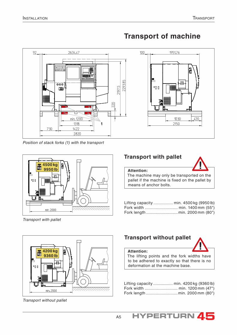
Transport of machine
Transport with pallet
Transport with pallet
Lifting capacity ................ min. 4500 kg (9950 lb)Fork width ........................... min. 1400 mm (55")Fork length .......................... min. 2000 mm (80")
Lifting capacity ................ min. 4200 kg (9360 lb)Fork width ........................... min. 1200 mm (47")Fork length .......................... min. 2000 mm (80")
Transport without pallet
Position of stack forks (1) with the transport
Transport without pallet
Attention:The machine may only be transported on the pallet if the machine is fixed on the pallet by means of anchor bolts.
Attention:The lifting points and the fork widths have to be adhered to exactly so that there is no deformation at the machine base.
1
4500 kg9950 lbkg
4200 kg9360 lbkg

A6
instAllAtiontrAnsport sAfety deviCes
Transport safety devices
Attention:• Prior to start-up of the machine all transport
devices have to be removed.• Keep the transport safety devices and re-
mount them when transporting the ma chine again.
Transport safety device A / machine doorThe chip protection door is secured by the door protection A.
• Remove the safety device A by unscrewing the hexagonal screws.
Transport safety device B / slidesThe transport safety device B serve to fix the slide positions during transport of the machine.Thus the gravity centre of the machine is fixed. Always make sure that the machine will only be transported with the transport safety devices be-ing mounted.
• Loosen the sheet metal (B4) both from the sheet metal (B3) and the upper tool turret.
• Loosen the sheet metal (B2) both from the sheet metal (B1) and the lower tool turret.
• Loosen the sheet metal (B3) both from the sheet metal (B1) and the sub spindle and remove it.
• Demount the sheet metal (B1) from the main spindle.
Note:Do not completely close the machine door after having removed the transport safety device! Otherwise the door will be locked and cannot be opened again!Unlocking the door is only possible when the machine is switched on (the machine has to be connected to the power supply system!).
A
Transport safety device "A" machine door
Transport safety device "B" of the slides
B4B3B2B1

A7
instAllAtion instAllAtion plAn
Installation plan, dimensions of the machineBasic machine
21 1
3
2
5 4
4
2
Options:1 Automatic machine door2 Oil mist seperator3 Machine status lamp
4 conveying device for machined parts
5 PC-keyboard
Setting screws resp. levelling elements (see "In-stallation criteria" in this chapter).
Bores ø18×120 (dia. 0.709"×4.72") for anchor bolts
Space for operation and maintenance
A
B

A8
instAllAtioninstAllAtion plAn
Machine with bar loader EMCO LM 1200
Machine with bar loader EMCO TOP LOAD 8-45
A9
instAllAtion drill templAte
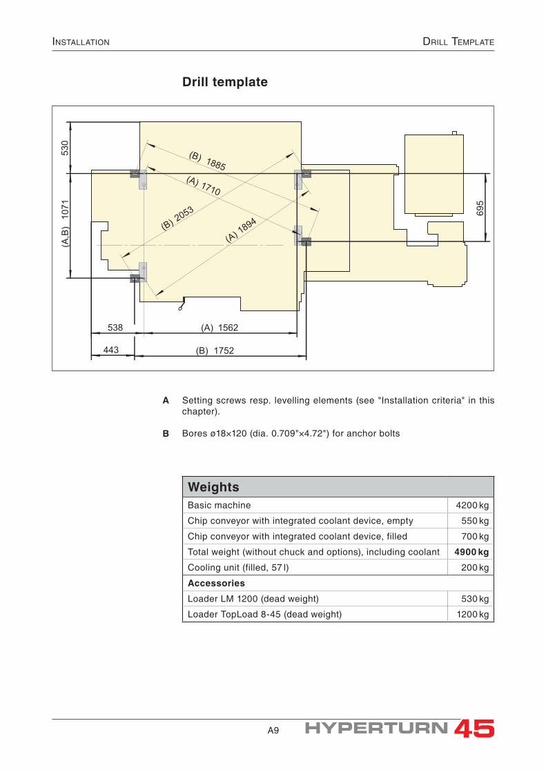
Drill template
Setting screws resp. levelling elements (see "Installation criteria" in this chapter).
Bores ø18×120 (dia. 0.709"×4.72") for anchor bolts
A
B
443
538
(B) 1752
(A,B)1071
695
(B)205
3
(B) 1885
(A) 1562
530
(A)189
4
(A) 1710
WeightsBasic machine 4200 kg
Chip conveyor with integrated coolant device, empty 550 kg
Chip conveyor with integrated coolant device, filled 700 kg
Total weight (without chuck and options), including coolant 4900 kg
Cooling unit (filled, 57 l) 200 kg
Accessories
Loader LM 1200 (dead weight) 530 kg
Loader TopLoad 8-45 (dead weight) 1200 kg

A10
InstallatIonInstallatIon CrIterIa
0°
80 Nm
30 Nm
Z
3
1
2
3 4
5
Installation criteriaRequirements on installation surfaceThe machine is to be installed on a pavement as horizontal as possible with adequate carrying power and vibration stability. When screwing down the machine bores for the anchor bolts have to be mounted.
Installation possibilities
Anchoring on the groundRequired accessories (order number):1 set fastening material ........................S3Z 460(consisting of 4 levelling elements, 4 fixing angles and 4 anchor bolts)
• Drill 4 anchor bolts ø18 × 120 (dia. .709"×4.72") in a distance of 1752 × 1071 (695) mm [68.98" × 42.17" (27.36")] (see installa tion plan).
• Place the machine above the bores.• Insert levelling elements (4) and align machine
horizontally.• Loosen setting angles (2) at the screws (1).• Thread in achor bolts (3) and push them into
the anchor bore until the distance between the washer of the anchor bolt and the setting angle (2) is approx. 5 mm (.197") (see sketch).
• Retighten setting angle (2).• Pretension anchor bolts (3) with 80 Nm
(59 ft·lbf). (anchorage in the ground)• Reloosen hexagon nuts of the anchor bolts and
attach insulating disk (5).• Tighten anchor bolts with 30 Nm (22 ft·lbf)
(holding down the machine).
Detail Z: anchoring on the ground
Aligning the machine
Operating conditionsThe ambient temperature for EMCO-machines has to be between min. +10°C (+50 F) and max. 35°C (+95 F) to guarantee the following:
• indicated manufactoring accuracy• function of the machine• working life of the machine
Note:When using a bar feed magazine or bar loader the machine has to be anchored on the ground.

A11
instAllAtion instAllAtion CriteriA
4 6 7 8
Without anchorage on the ground• Insert levelling elements (4) and align machine
horizontally.
Installation without anchorage
Notes:• If the machine is not anchored, you can also
use setting screws M20×80 DIN 933-8.8 (8) with counter nuts (7) instead of levelling elements.
• Steel plates �100×20 (6) have to be placed below the setting screws.Mind: no vibration damping!
Additional installation criteriaIn addition to the required capacity and vibra-tion stability further requirements are to be met by the installation surface and the installation site:
• The installation site has to comply with build-ing authority regulations so that in case of possible leakage of cooling lubricant, lubri-cating and hydraulic oil, the environment is not burdened.An ideal situation would be provided if the installtion site at the same time fulfilled the function of a collecting tray.
• The room where the machine is installed, should be high and well ventilated.Please observe the guidelines for workplace safety (the permissible MAK- und TRK values must not be exceeded; if necessary, please use an oil mist separator).
• Vibration-proof features as favourable as possible to avoid a transmission of vibrations (particularly when working in the upper speed range, with bar work, when machining heav-ily unbalanced workpieces, with interrupted cut, when using driven tools etc.) to nearby objects.
• Good and sufficient lighting of the working space facilitates operation of the machine and increases quality and security of work.
• Unfavourable light and sun radiation may lead to reflections on the control screen and, thus, impair the visibility of information items.
• The specific noise load of a machine operator is to be noted.
• It has to be taken into account that in accor-dance with the operating situation a highly qualified operator works on the lathes who has to carry out exacting programming and supervising activities.Sometimes the situation can be improved by sound insulation walls.From studies we know that the double dis-tance to a nearby source of noise de creases the sound level by 3 to 5 dB(A).When doubling the number of similar sources of noise the level is increased by 3 dB(A).
• Heat sources with inconstant temperature near the machine as well as air drafts will in-fluence the quality of the place of work as well as the operating position of the machine. If necessary, adequate measures for pro tection are to be taken.
MAK is the maximum concentration of a substance in the ambient air in the workplace which has no adverse effect on the workers` health.TRK is the concentration of a substance in the ambient air in the workplace that can be achieved using technically available measures.

A12
instAllAtionmounting - Chip Conveyor
21
c
ab
23
Position the chip conveyor next to the machine
Mounting of the chip conveyorThe chip conveyor (1) is separately delivered on a pallet.The coolant device is integrated into the chip conveyor.The coolant pumps are already mounted and electrically connected.
Positioning the chip conveyor• Push the chip conveyor (1) from the right-hand
side under the machine up to a slight stop.
• Turn all 4 support elements at the chip conveyor (1) downwards until the transport rollers are relieved.
Fix the support elements (2) in this position by locknuts.
Positioning the guiding sheetsThe correct positioning of the guiding sheets is important in order to prevent chips and coolant from getting out of the machine room.
• Open the machine door and push the guiding sheets (a), (b) and (c) upwards until they come to a stop.
• Fix the guiding sheets in this position by tighten-ing the clamping screws.
• Mount the cover (3). The cover and the respective screws are in-
cluded in the delivery.
Caution:Prior to pulling the chip conveyor out, make sure that the guiding sheets point downwards!Thereby, damages at the machine and at the coolant tank will be avoided.
Positioning of the guiding sheets
A13
instAllAtion
A13
mounting - Chip Conveyor
2
4
13
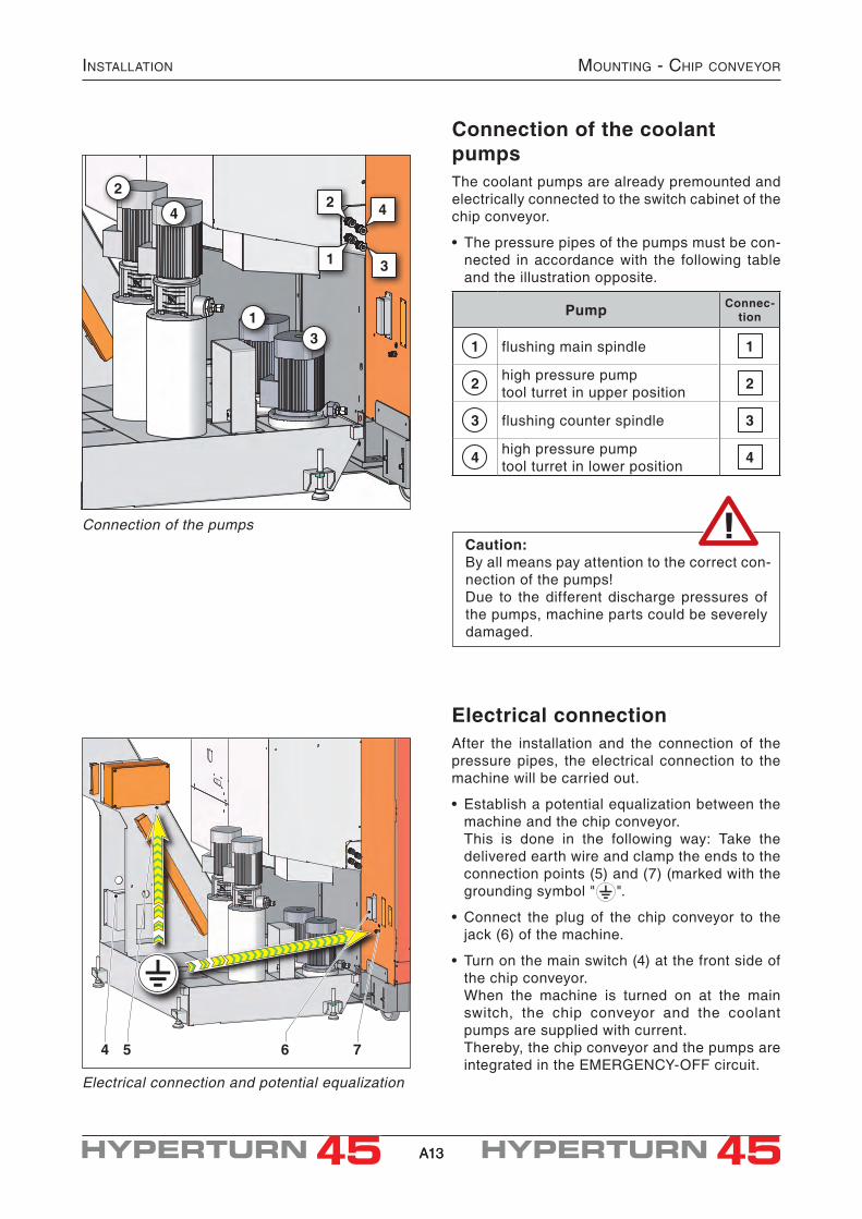
Pump Connec-tion
1 flushing main spindle 1
2 high pressure pump tool turret in upper position 2
3 flushing counter spindle 3
4 high pressure pump tool turret in lower position 4
4 5 6 7
1
2
3
4
Connection of the pumps
Electrical connection and potential equalization
Connection of the coolant pumpsThe coolant pumps are already premounted and electrically connected to the switch cabinet of the chip conveyor.
• The pressure pipes of the pumps must be con-nected in accordance with the following table and the illustration opposite.
Caution:By all means pay attention to the correct con-nection of the pumps!Due to the different discharge pressures of the pumps, machine parts could be severely damaged.
Electrical connectionAfter the installation and the connection of the pressure pipes, the electrical connection to the machine will be carried out.
• Establish a potential equalization between the machine and the chip conveyor.
This is done in the following way: Take the delivered earth wire and clamp the ends to the connection points (5) and (7) (marked with the grounding symbol " ".
• Connect the plug of the chip conveyor to the jack (6) of the machine.
• Turn on the main switch (4) at the front side of the chip conveyor.
When the machine is turned on at the main switch, the chip conveyor and the coolant pumps are supplied with current.
Thereby, the chip conveyor and the pumps are integrated in the EMERGENCY-OFF circuit.

A14
instAllAtion
A14
refrigerAtor
RefrigeratorThe refrigerator is necessary for cooling the main drives.
ConnectionThe hoses are already mounted on the machine and equipped with blocking valves.
Forerun:• Connect the outlet-valve (1) of the refrigerator
with the valve of the upper hose (5) on the ma-chine.
Reverse running:• Connect the inlet-valve (2) of the refrigerator with
the valve of the lower hose (6) on the machine.
• Open all four valves.
Filling the cooling unitThe cooling unit is delivered with a canister con-taining 25 l antifreeze.
Mixing ratioantifreeze : water = 1 : 3
total filling quantity: ..................... 57 l (15 USgal)antifreeze (1:3) .................. approx. 15 l (4 USgal)freeze protection .................... up to –15 °C (5 °F)
• The filling opening is reached by removing the side panel at the cooling unit.
It is located at the upper side of the tank.
• The filling level must reach the "Max"- mark at the level indicator (4) when the valves are open.
Electrical connection• Establish a potential equalization between the
machine and the chip conveyor. This is done in the following way: Take the
delivered earth wire and clamp the ends to the connection points (3) and (6) (marked with the grounding symbol " ".
• Connect the plug of the chip conveyor to the jack (5) of the machine.
• Turn on the cooling unit at the main switch. When the machine is switched on, the cooling
unit is automatically turned on as well. Thereby, it is also integrated in the EMERGEN-
CY-OFF circuit.
1 2 3 4 5 6 7 8
Cooling unit with connections
Caution:• It is absolutely not allowed to operate the
machine without the cooling unit being con-nected and switched on.
� Severe damages at the main spindle and the sub spindle could be the result.
• The valves must be open.• The factory settings of the cooling unit must
not be modified, so as to avoid damages at the spindle drives!
A15
instAllAtion rolling support
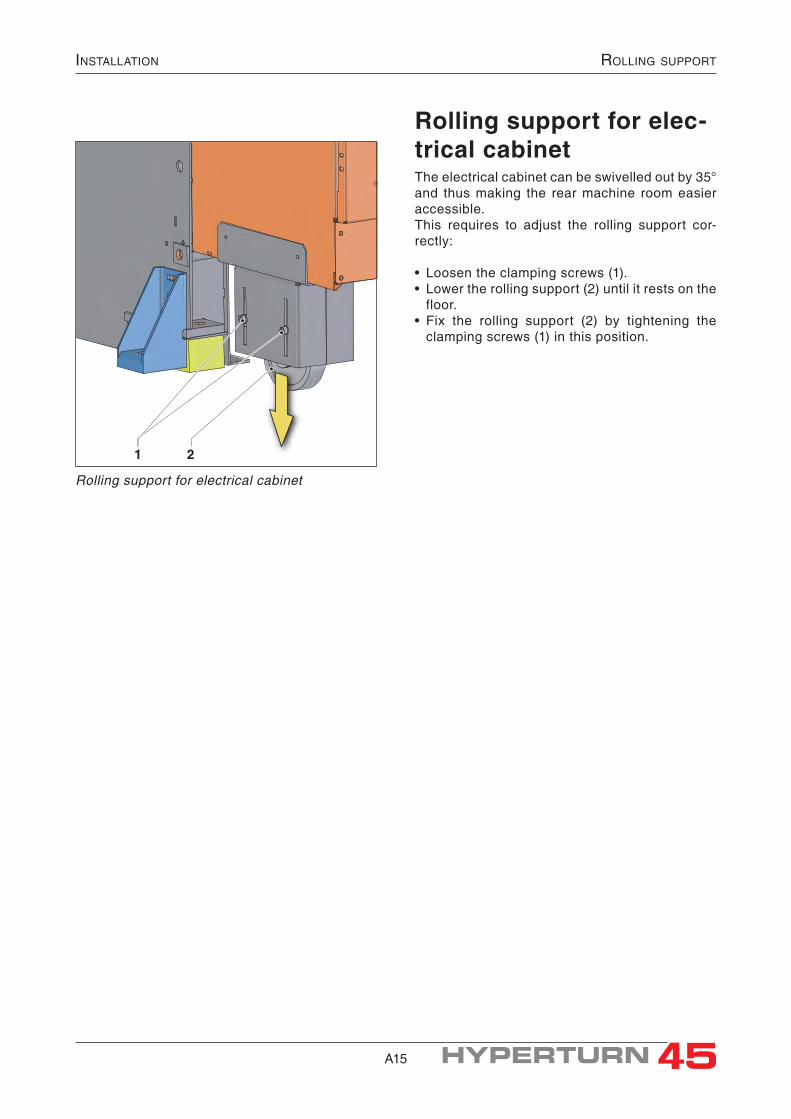
1 2
Rolling support for elec-trical cabinetThe electrical cabinet can be swivelled out by 35° and thus making the rear machine room easier accessible.This requires to adjust the rolling support cor-rectly:
• Loosen the clamping screws (1).• Lower the rolling support (2) until it rests on the
floor.• Fix the rolling support (2) by tightening the
clamping screws (1) in this position.
Rolling support for electrical cabinet

A16
instAllAtioneleCtriCAl ConneCtion
Danger:The electrical connection of the machine and its accessories may only be established by an electric expert.Feed cables must be idle during the connec-tion.
Electrical connection
Attention:Connecting this machine to a mains protected by leakage current circuit breaker is admitta-ble only with using an all-current-sensitive leakage current breaker.
Reason:The drives used for this machine can cause DC leakage currents which will impair the protective function of the leakage current breaker (no release).
Types of the all-current-sensitive leakage cur-rent breaker tested by EMCO:
SIEMENS 5SM3646-5EMCO Bestell-Nr. ZME 280 720ABB F804 - 63/0,3
PE
L1 L2 L3
L1 L2 L3
T1 T2 T3
terminal strip=1+L1-PE1
main switch=1DA0.C0-Q0
• Thread feed cable (2) through the cable screwed connection (1) lateral on the electrical cabinet.
• Connect the three phases L1, L2 and L3 to main switch +1DA0.C0-Q0 (3).
• Connect earth contact (yellow/green core) to the PE terminal strip =1+L1-PE1 (4).
• Tighten cable screwed connection (1).
Control of the correct connectionFor right function of the machine, it has to bt con-nected to a right rotating field.Check the connection before the initial start-up at the check-points T1, T2 and T3 on the main switch (3) of the machine.
Main switch and PE-clamping strip
L1 L2 L3 PE L1 L2 L3 PEL1 ——L2 400 V ——L3 400 V 400 V ——PE 230 V 230 V 230 V ——
1 2
4 3
2
5 3
Checking correct connection

A17
InstallatIon ElEctrIcal connEctIon / PnEumatIc connEctIon
Mains connection data
Power supply ................................ 3/PE ~ 400 VFrequency ........................................... 50/60 HzMax. voltage fluctuations .................. +10 / –10%Connected load ...................................... 30 kVAPreliminary fuse .............................80 A/gG, gLRequired short circuit power ................2500 kVAFeed cross section ............................. 4×25 mm²
Attention:A preliminary fuse is ordered forcible!The specified value of the fuse and the cables has to be kept strictly.
Note:Further information about electrical connection is to be found in the electrical documentation of your machine. In case of different specifications the data in the electrical documentation are valid.
Lateral side of the machine - pneumatic connection
Pneumatic connectionSupply pressure ............................6 bar (87 psi)Supply quantity ...... at least 5 l/min (1.32 USgal/min)
• Connect the air supply at the fitting (3) of the pneumatic unit at the side of the machine (compressedair connection ø10 mm).
• The pneumatic service unit is supplied with compressed air when the hand valve (2) is pushed upwards.
• The set air pressure can be read off the machine`s manometer (1).
1
2
3
p = 6 bar

A18
instAllAtioninitiAl stArt-up
Initial start-up• All bright parts are sprayed with oil-soluble
preservation agent and need not be treated prior to initial start-up.
• Check, if the following components are already mounted and correctly installed and switched on:- Chip conveyor with integrated coolant device- Refrigerator for spindle cooling
• Check the oil level for the central lubrication on the rear side of the machine on the tank (2), if necessary refill oil.
• Connect compressed air (4).
• Check oil level of the hydraulics on the oil level gauge on the left side of the machine, if neces-sary refill oil in the filler neck (3).
• Fill coolant into coolant tanks (5) (filling capacity 200 l (53 USgal); also see coolant recommenda-tions).
• Switch on machine at main switch (1).
• Taste "AUX-ON" am Bedienpult der Steuerung Press "AUX-ON" key on the operation panel of the control, thus the auxiliary units are switched on.
After major standstills this key should be sub-sequently pressed various times and in case of initial start approx. 10 times.
Every time the key is pressed a lubricating impulse is emitted to the slideways and ball screws.
• Further operation is described in chapter "Op-eration and Programming EMCO specific".
Attention:The machine must never be operated without a functioning refrigerator!
"AUX-ON"-key and coolant tank
pneumatic connection
main switch, central lubrication and hydraulic unit
1 2 3
4
5
Notes:• Filling quantities, qualities and re commen-
dations for lubricants, hydraulic oil and cool-ing lubricant are to be found in the chapter "Maintenance".
• In case that no hydraulic pressure is built up after switching on the auxiliary drives (key "AUX ON"), the mains connection is probably wrong (wrong rotary field).Remedy: Clamp two phases interchanged (see Electrical documentation).

15
Technical DaTa - MeTric
Working rangeSwing over bed [mm] ø430Swing over cross slide [mm] ø300Max. turning diameter [mm] ø300Max. part length [mm] 480Max. bar work diameter standard (option "BigBore") [mm] ø45 (ø51)Distance main spindle - counter spindle (fixing flanges) [mm] 720
TravelsTravel X / X2 [mm] 160 / 150Travel Z / Z2 / Z3 [mm] 510 / 510 / 510Travel Y (option) [mm] +40 / –30
Main spindle (spindle 1)Spindle connection - DIN 55026 KK 5Spindle bore [mm] ø53Spindle bearing (inside diameter) [mm] ø85Max. permissible inertia for clamping device and workpiece [kgm²] 0,08
Main spindle - clamping systemClamping cylinder with bore with tension tube, max. bar diameter [mm] ø45 (ø51)Max. size of chuck standard (option "BigBore") [mm] ø160 (ø175)
Main spindle - driveIntegrated AC-spindle motor, Power (100%/40% d.c.) [kW] 11 / 15Speed range (infinitely variable) [min-1] 0 - 7000Max. torque at the spindle [Nm] 100
Counter spindle (spindle 2)Spindle connection - DIN 55026 KK 5Spindle bore [mm] ø53Spindle bearing (inside diameter) [mm] ø85Travel Z3 [mm] 510Rapid traverse speed [m/min] 45Max. permissible inertia for clamping device and workpiece [kgm²] 0,08
Counter spindle - clamping systemClamping cylinder with bore and tensioning tube, integrated pneum. actuated ejectorMax. size of chuck [mm] ø160
Counter spindle - driveIntegrated AC-spindle motor, Power (100%/40% d.c.) [kW] 11 / 15Speed range (infinitely variable) [min-1] 0 - 7000Max. torque at the spindle [Nm] 100
C-axes (spindles 1 and 2)Resolution of the round axis [°] 0,001Rapid traverse Sinumerik / Fanuc [min-1] 1000 / 100
Technical Data of the Machine - metric
Subject to technical modifications!In case the data differ from the technical specification, the values indicated there are valid!

16
teChniCAl dAtA - metriC
Feed drivesRapid speed X / Z [m/min] 30 / 45Rapid speed Y (option) [m/min] 15Feeding force X [N] 4000Feeding force Z / Z2 / Z3 [N] 5000/5000/6000Feeding force Y (option) [N] 4000Positioning variation PS acc. to VDI 3441 at X / Y / Z [µm] 3 / 3 / 3
Tool system 1 and 2 (upper and lower system)Revolver-type tool turret radial with direction logic, with driven toolsNumber of tool stations for each tool turret 12Toolholding fixtures acc. to DIN 69880 VDI 25Shank height for square tools [mm] 16×16Shank diameter for boring bars [mm] ø25Turret indexing time [sec] 0,2Driven tool stations (clutch acc. to DIN 5480)Number of driven tool stations for each tool turret 12Speed range [min-1] 0 - 6000Max. output [kW] 4Max. torque [Nm] 16Max. d.c. with max. speed or output [%] 25
Coolant deviceTank capacity [l] 200Power with 3,5 bar / 10 bar [kW] 0,62 / 1,1Delivery power with 3,5 bar / 1 bar [l/min] 12,5 / 58Delivery power 10 bar / 5 bar [l/min] 15 / 40
Hydraulic unitMulit circuit hydraulic unit for power chuck and tool turretFilling level [l] 11Operating pressure [bar] 70 - 80Max. pressure for clamping device [bar] 60
Pneumatic unitSupply pressure [bar] 6Supply quantity [l/min] 5
Lubricating systemGuideways, ballscrews autom. central oil lubricationMain sindle, counter spindle greas lubrication
Chip conveyor24-pole plug for assembly chip conveyor included in basic machineDischarge height [mm] 1200
Subject to technical modifications!In case the data differ from the technical specification, the values indicated there are valid!

17
teChniCAl dAtA - metriC
Workpiece collection device (option)Pneumatic operation, actuating pressure [bar] 6Max. length of finished parts [mm] 120Max. diameter for finished parts [mm] ø45Max. weight of finished parts [kg] 2,0
Operating conditionsRequired ambient temperature [°C] +10 to +35
Electrical connectionPower supply [V] 400 ~3/PEMax. voltage fluctuation [%] 50 / 60Frequency [Hz] ±10Connected load value [kVA] 30Preliminary fuse for the machine [A/gG,gL] 80Required short circuit power [kVA] 2500Resistance to short circuits [kAeff] 10Wire size [mm²] 4×25
ColoursLight-grey RAL 7040Red RAL 3020Black RAL 9004
Dimensions / weightsHeight of turning axis above floor [mm] 1126Total height (incl. oil mist seperator) [mm] 2325Installation surface (incl. chip conveyor, without refrigerator) [mm] 3830×1950Weight of the machine without chip conveyor [kg] 4200
Sound pressure levelMediated sound pressure level [db(A)] 78
With the following conditions:
Measuring methode: enveloping surface according to DIN 45 635Measure point: 1 m distance and 1,6 m above groundOperating mode: maximum speed during idle running
Explanation:The so called numerical values are noise emission levels and not necessarily safe working levels. Although there is a cor-relation between the degree of the noise level and the degree of the noise exposure, it cannot be used reliably to determine whether additional protective measures are necessary or not. Among the factors influencing the actual degree of noise ex-posure of the employees are the characteristics of the working area, the other sources of noise, i.e. the number of machines as well as processes taking place in the vicinity and the duration of noise exposure. Aside from that, the permissible noise level may differ from country to country. However, the information should enable the machine operator to better evaluate the hazards and risks.
Subject to technical modifications!In case the data differ from the technical specification, the values indicated there are valid!

18
blank page

19
Technical DaTa - inch
Working rangeSwing over bed [in] ø16.93Swing over cross slide [in] ø11.81Max. turning diameter [in] ø11.81Max. part length [in] 18.9Max. bar work diameter standard (option "BigBore") [in] ø1.77 (ø2)Distance main spindle - counter spindle (fixing flanges) [in] 28.35
TravelsTravel X / X2 [in] 6.3 / 5.9Travel Z / Z2 / Z3 [in] 20 / 20 / 20Travel Y (option) [in] +1.58 / –1.18
Main spindle (spindle 1)Spindle connection - DIN 55026 KK 5Spindle bore [in] ø2.09Spindle bearing (inside diameter) [in] ø3.35Max. permissible inertia for clamping device and workpiece [LBM-in²] 273
Main spindle - clamping systemClamping cylinder with bore with tension tube, max. bar diameter [in] ø1.77 (ø2)Max. size of chuck standard (option "BigBore") [in] ø6.3 (ø6.9)
Main spindle - driveIntegrated AC-spindle motor, Power (100%/40% d.c.) [hp] 14.8 / 20.1Speed range (infinitely variable) [r.p.m.] 0 - 7000Max. torque at the spindle [ft·lbf] 73.8
Counter spindle (spindle 2)Spindle connection - DIN 55026 KK 5Spindle bore [in] ø2.09Spindle bearing (inside diameter) [in] ø3.35Travel Z3 [in] 20Rapid traverse speed [ft/min] 147Max. permissible inertia for clamping device and workpiece [LBM-in²] 273
Counter spindle - clamping systemClamping cylinder with bore and tensioning tube, integrated pneum. actuated ejectorMax. size of chuck [in] ø6.3
Counter spindle - driveIntegrated AC-spindle motor, Power (100%/40% d.c.) [hp] 14.8 / 20.1Speed range (infinitely variable) [r.p.m.] 0 - 7000Max. torque at the spindle [ft·lbf] 73.8
C-axes (spindles 1 and 2)Resolution of the round axis [°] 0,001Rapid traverse Sinumerik / Fanuc [min-1] 1000 / 100
Technical Data of the Machine - inch
Subject to technical modifications!In case the data differ from the technical specification, the values indicated there are valid!

20
teChniCAl dAtA - inCh
Feed drivesRapid speed X / Z [ft/min] 98 / 147Rapid speed Y (option) [ft/min] 49Feeding force X [lbf] 899Feeding force Z / Z2 / Z3 [lbf] 1124/1124/1349Feeding force Y (option) [lbf] 899Positioning variation PS acc. to VDI 3441 at X / Y / Z [µm] 3 / 3 / 3
Tool system 1 and 2 (upper and lower system)Revolver-type tool turret radial with direction logic, with driven toolsNumber of tool stations for each tool turret 12Toolholding fixtures acc. to DIN 69880 VDI 25Shank height for square tools [in] 0.63×0.63Shank diameter for boring bars [in] ø0.98Turret indexing time [sec] 0,2Driven tool stations (clutch acc. to DIN 5480)Number of driven tool stations for each tool turret 12Speed range [r.p.m.] 0 - 6000Max. output [hp] 5.4Max. torque [ft·lbf] 11.8Max. d.c. with max. speed or output [%] 25
Coolant deviceTank capacity [USgal] 53Power with 3,5 bar / 10 bar [hp] 0.83 / 1.48Delivery power with 3,5 bar / 1 bar [gal/min] 3.3 / 15.3Delivery power 10 bar / 5 bar [gal/min] 4. / 10.6
Hydraulic unitMulit circuit hydraulic unit for power chuck and tool turretFilling level [USgal] 2.9Operating pressure [psi] 1015 - 1160Max. pressure for clamping device [psi] 870
Pneumatic unitSupply pressure [psi] 87Supply quantity [gal/min] 1.3
Lubricating systemGuideways, ballscrews autom. central oil lubricationMain sindle, counter spindle greas lubrication
Chip conveyor24-pole plug for assembly chip conveyor included in basic machineDischarge height [in] 47
Subject to technical modifications!In case the data differ from the technical specification, the values indicated there are valid!

21
teChniCAl dAtA - inCh
Workpiece collection device (option)Pneumatic operation, actuating pressure [psi] 87Max. length of finished parts [in] 4.72Max. diameter for finished parts [in] ø1.77Max. weight of finished parts [lb] 4.4
Operating conditionsRequired ambient temperature [°F] +50 to +95
Electrical connectionPower supply [V] 400 ~3/PEMax. voltage fluctuation [%] 50 / 60Frequency [Hz] ±10Connected load value [kVA] 30Preliminary fuse for the machine [A/gG,gL] 80Required short circuit power [kVA] 2500Resistance to short circuits [kAeff] 10Wire size [in²] 4×25
ColoursLight-grey RAL 7040Red RAL 3020Black RAL 9004
Dimensions / weightsHeight of turning axis above floor [in] 44.3Total height (incl. oil mist seperator) [in] 91.5Installation surface (incl. chip conveyor, without refrigerator) [in] 151×77Weight of the machine without chip conveyor [lb] 9260
Sound pressure levelMediated sound pressure level [db(A)] 78
With the following conditions:
Measuring methode: enveloping surface according to DIN 45 635Measure point: 1 m distance and 1,6 m above groundOperating mode: maximum speed during idle running
Explanation:The so called numerical values are noise emission levels and not necessarily safe working levels. Although there is a cor-relation between the degree of the noise level and the degree of the noise exposure, it cannot be used reliably to determine whether additional protective measures are necessary or not. Among the factors influencing the actual degree of noise ex-posure of the employees are the characteristics of the working area, the other sources of noise, i.e. the number of machines as well as processes taking place in the vicinity and the duration of noise exposure. Aside from that, the permissible noise level may differ from country to country. However, the information should enable the machine operator to better evaluate the hazards and risks.
Subject to technical modifications!In case the data differ from the technical specification, the values indicated there are valid!

22
blank page