zw3d what’s new
TRANSCRIPT

ZW3D WHAT’S NEW V 2021
ZWSOFT CO., LTD.(Guangzhou)

1
Copyright and Trademarks © Copyright 2021 ZWSOFT CO., LTD.(Guangzhou). All rights reserved. Room 01-08, 32/F, No.15, Zhujiang West Road, Tianhe District, Guangzhou 510623, China (8620)38289780
ZW3D™ V2021 What’s New This documentation may be reproduced provided it complies with the terms presented on the LICENSE AGREEMENT supplied. ZWSOFT CO., LTD.(Guangzhou) and the program authors have no liability to the purchaser or any other entity, with respect to any liability, loss, or damage caused, directly or indirectly by this software and training materials, including but not limited to, any interruptions of service, loss of business, anticipatory profits, or consequential damages resulting from the use of or operation of this software. Updates may be made to this documentation and incorporated into later editions. ZW3D™ is a registering trademark of ZWSOFT CO., LTD.(Guangzhou). The ZW3D™ logo is a registering trademark of ZWSOFT CO., LTD.(Guangzhou). ZWCAD™, ZWSOFT™, the ZWCAD™ logo, and the ZWSOFT™ logo are all trademarks of ZWSOFT CO., LTD.(Guangzhou). Printed in the P. R. China.

I
Contents Highlights of ZW3D 2021 ..................................................................................... 1
1 Basic ..................................................................................................... 2
1.1 UI & Workflow ................................................................................ 2
1.1.1 ★New “Command Search” ................................................................... 2
1.1.2 ★New “Map Key” ............................................................................ 3
1.2 Equation Manager ............................................................................ 5
1.2.1 External Excel Association and Drive Updates Support ...................................... 5
1.2.2 Equation Manager Improvement ............................................................. 5
1.3 Crash Report Improvement ................................................................... 6
2 Converter ................................................................................................ 8
2.1 Import Format Update ........................................................................ 8
2.2 ★Adjustment to “Quick Import” ............................................................. 9
2.2.1 Adjustment to “Quick Import” UI ............................................................ 9
2.2.2 Add Import Feature Node to “Quick Import” ............................................... 10
2.2.3 2nd Import Action in “Quick Import” (Import Real Geometric Data) ........................ 11
2.2.4 Remove “Quick View” ....................................................................... 11
2.3 ★Convert Attributes Support ............................................................... 12
2.4 Other Adjustment ............................................................................ 13
2.4.1 DWG/DXF Export Add "Explode hatch as single line" Option ............................... 13
2.4.2 DWG/DXF Import Add “Placement” Field ................................................... 14
3 CAD ..................................................................................................... 15
3.1 Sketch Design ................................................................................ 15
3.1.1 Improvement of “Conflicting Constraints Check” ........................................... 15
3.1.2 ★New “Equal Curvature” ................................................................... 15
3.1.3 New Character Spacing in ReadySketch Text................................................ 16
3.1.4 Support Relocate Sketch Plane, Sketch Direction and Sketch Origin in Sketch Editing .... 17
3.1.5 ★New Cosmetic Sketch ..................................................................... 17
3.1.6 Display tinted closed ring .................................................................... 18
3.1.7 New “2D Sketch Offset Constrain” .......................................................... 19

II
3.1.8 New Option of “Hide used sketch” .......................................................... 19
3.2 Wireframe Design ............................................................................ 20
3.2.1 Improvement of “Project Curve” ............................................................ 20
3.2.2 Improvement of “Curve Modify” Align Type ................................................ 20
3.3 Part Design ................................................................................... 21
3.3.1 ★Modeling Dimensional Accuracy Update ................................................. 21
3.3.2 ★Complete CSYS Support ................................................................... 21
3.3.3 New Method to Create Datum Plane........................................................ 28
3.3.4 Geometries Direct Cross File Copy via "Ctrl+C/Ctrl+V" Support ............................ 28
3.3.5 ★New Cross-section Type “G2 Blend” in Fillet Command ................................. 29
3.4 Free Form Design ............................................................................ 30
3.4.1 New “Cross Trim” ............................................................................ 30
3.4.2 ★"Blend Face" Command New Option "G2 Blend" ........................................ 30
3.4.3 ★"Fillet Open Faces" command New sub menu "Shape of Fillet" ......................... 31
3.5 Sheet Metal Design .......................................................................... 32
3.5.1 ★New “Zero Radius Flange” ................................................................ 32
3.5.2 Improvement of “Punch” .................................................................... 33
3.6 ECAD ......................................................................................... 35
3.6.1 Import IDF File ............................................................................... 35
3.6.2 Export IDF File ................................................................................ 36
3.6.3 New “Create” ECAD Module ................................................................. 37
3.7 Assembly Design ............................................................................. 41
3.7.1 New “Dissolve Sub-assembly” ............................................................... 41
3.7.2 New “Group as Sub-assembly” .............................................................. 41
3.7.3 “Edit Constraint” Support Multi-select Components and Search Mutual Constraints ..... 42
3.7.4 New “Filter” in Assembly Tree ............................................................... 43
3.7.5 ★New “Clearance Check” ................................................................... 43
3.7.6 ★New “Batch Attribute Edit” ............................................................... 44
3.7.7 New “Include unplaced component” ........................................................ 45
3.8 Drafting Design ............................................................................... 46

III
3.8.1 Variable Input in Engineering Drawing Show Label Support ................................ 46
3.8.2 ★New “Point Table” and “Dimension Table” ............................................... 47
3.8.3 New Insert “OLE Object”..................................................................... 51
3.8.4 New 2D BOM Default Template Setting in Configuration .................................. 51
3.9 ZWMold ...................................................................................... 52
3.9.1 “Trim Pin” Support to Select Multiple Components as Trim Body ......................... 52
4 CAM .................................................................................................... 53
4.1 ★Enhancements of Full Machine Simulation ............................................... 53
4.2 ★The Rough Turning Operation Supports Arbitrary Contour as Stock ..................... 57
4.3 New Arc Fitting Functionality in 2X Operation .............................................. 58
4.4 ★New Arc Fitting Functionality in Surface Engraving Operation and 5X Operations ...... 59
4.5 New Regular Pentagon, Hexagon and Octagon Turning Tools.............................. 59
4.6 ★New Excel Format of Operation List ...................................................... 60
4.7 Independent the Web Editor Program of the Zw3D Post ................................... 62
4.8 New Tool Path Verification Progress Bar .................................................... 63
4.9 Support the Left to Right Cutting Direction in Groove operation .......................... 63
4.10 ★Support the G68.2 Functionality .......................................................... 64
4.11 New Limit Stepover Option in QM Roughing Operations ................................... 64
4.12 New Stepdown Type and Stepdown items in Spreadsheet ................................. 65
4.13 Distinguish the Type of Input Value for the Speed Feed Table ............................. 66

1
Highlights of ZW3D 2021 Basics: New “Command Search”
New “Map Key”
Translator: Adjustment to “Quick Import”
Convert Attributes Support
CAD: New “Equal Curvature”
New “Cosmetic Sketch”
Modeling Dimensional Accuracy Update
Complete CSYS Support
New Cross-section Type “G2 Blend” in Fillet Command
"Blend Face" Command New Option "G2 Blend"
"Fillet Open Faces" command New sub menu "Shape of Fillet"
New “Zero Radius Flange”
New “Clearance Check”
New “Batch Attribute Edit”
Drafting: New “Point Table” and “Dimension Table”
CAM: Enhancements of Full Machine Simulation
The Rough Turning Operation Supports Arbitrary Contour as Stock
New Arc Fitting Functionality in Surface Engraving Operation and 5X Operations
New Excel Format of Operation List
Support the G68.2 Functionality
Note: Important enhancements in this article are marked with

2
1 Basic
1.1 UI & Workflow
1.1.1 ★New “Command Search”
Use “Command Search” to search by character matching and each search history will be recorded. The
search records are ordering by time with the latest ones ahead. The search object includes the command
name and the command description. As for search results, they will display in multiple pages with each
page of 30 items and provide the functions of the page running and page number. Support dynamic
displaying the search result command in current UI. User can directly execute the command search, but
only limit to the command in the current environment.

3
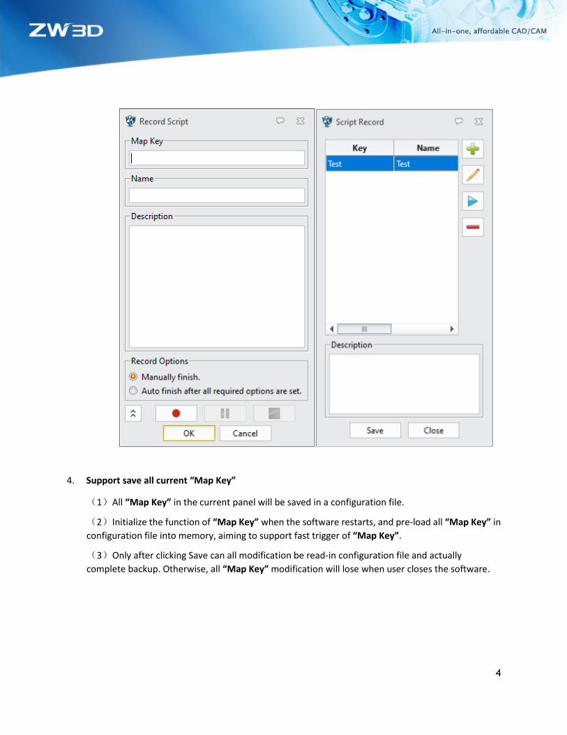
1.1.2 ★New “Map Key”
“Map Key” supports recording the workflow of a single command or multiple command groups to meet
quick completion of some batch design operation. User can input parameters for template command
and can add, delete, modify, and save “Map Key”.
Definition of “Map Key”
(1) “Map Key” supports all combinations of letters and numbers with 32 maximum characters.
(2) The widget layer will disable user’s input once irregular character input happens (such as control character and special character). All irregular input will be disposed in the method of neglect.
Add, delete, modify, and save “Map Key”
1. Support addition of “Map Key”
(1) Required inputs include “Map Key” and Name (64 maximum characters) while Description is
optional input. To select record action is supported.
(2)When “Map key” is empty, click OK and the interface will be saved, in case of user losing the
recording and input text when the user forgets to input “Map Key”.
2. Support deletion of single or multiple “Map Key”
(1) The deletion only targets at the contents of memory. Once user did not click Save, the
software would restore the deleted content while it was restarted.
3. Support modification of single “Map Key”
(1)When “Map Key” works as unique key, modification is not supported, nor the record option
modification.
(2)User can modify name and description of “Map Key” as well as re-record workflow of
command. However, the command workflow supports re-recording instead of fragment
modification.
(3)All modification works only after clicking OK; The button of Cancel can restore the contents
prior to modification, and even the re-recording flow can be restored.
4
4. Support save all current “Map Key”
(1)All “Map Key” in the current panel will be saved in a configuration file.
(2)Initialize the function of “Map Key” when the software restarts, and pre-load all “Map Key” in
configuration file into memory, aiming to support fast trigger of “Map Key”.
(3)Only after clicking Save can all modification be read-in configuration file and actually
complete backup. Otherwise, all “Map Key” modification will lose when user closes the software.

5
➔Where it is
Menus >> Utilities >> Script Record
1.2 Equation Manager
1.2.1 External Excel Association and Drive Updates Support
In equation manager, newly support external Excel association and drive updates. User can import
external Excel to equation manager and associate with it. When user modifies the content in Excel, the
associated content in equation manager will be synchronously updated. The button enables user
to break the association between equation and Excel. The associated expressions have link icons as below
shown.
➔Where it is
Part Environment >> Tools >> Insert >> Equation Manager
1.2.2 Equation Manager Improvement
Equation manager extends the physical quantity types and their unit types as well as 2 physical quantities including pressure temperature and their corresponding units.

6
Pressure Unit: Pa
kPa
MPa
psi
bars
atm
mmH2O
mmHg
inH2O
inHg
mN/mm^2
N/mm^2
N/cm^2
N/dm^2
N/m^2
lbf/in^2
lbf/ft^2
kgf/mm^2
kgf/cm^2
kgf/dm^2
kgf/m^2
at
Temperature Unit:
Celsius
Fahrenheit
Kelvin
Rankine
➔Where it is
Part Environment >> Tools >> Insert >> Equation Manager
1.3 Crash Report Improvement
Adapt to high resolution screen. With the improvement, the error report interface supports high
resolution screen as well as normally identifies user’s operational system information. Newly add CPU
information. The computer information will be sent along with sending error report. The interfaces of
application CrashReport and Manager have been merged to one application ZW3DCrashReport.exe .

7

8
2 Converter
2.1 Import Format Update
The following table shows the import format supported by ZW3D, and the newly update formats are
marked in RED.
Format Suffix Supported Version
Catia V4 .model, .exp, .session 4.1.9 – 4.2.4
Catia V5/V6 .CATPart, .CATProduct, CATDrawing, .CGR, .3DXML V5R8---V5/V6R2020
NX(UG) .prt 11– NX 1899
Creo(Pro/E) .prt, .prt*, .asm, .asm.* 16 – Creo 6.0
SolidWorks .sldprt, .sldasm 98– 2020(Only 64 bit supported)
SolidWorks_2D . slddrw 2013-2020(Only 64 bit supported)
SolidEdge .par, .asm, .psm V18 – SE2020
Inventor .ipt, .iam V6 -V2020
ACIS .sat, .sab, .asat, .asab R1 – 2020 1.0
DWG .dwg R11 - 2013
DXF .dxf R11 - 2013
IGES .ige, .iges
STEP .stp, .step, .stpz 203, 214, 242
Parasolid .x_t, .x_b, .xmt_txt, .xmt_bin Up to 30.0
VDA .vda
Image File *.bmp, *.gif, *.jpg, *.jpeg, *.tif, *.tiff
Neutral File *.z3n, *.v3n
PartSolutions *.ps2, *.ps3
STL *.stl
3DXML .3dxml 4.0 - 4.3
XCGM .x cgm R2012-2020 1.0
JT .jt 6.4-10.4
OBJ .obj

9
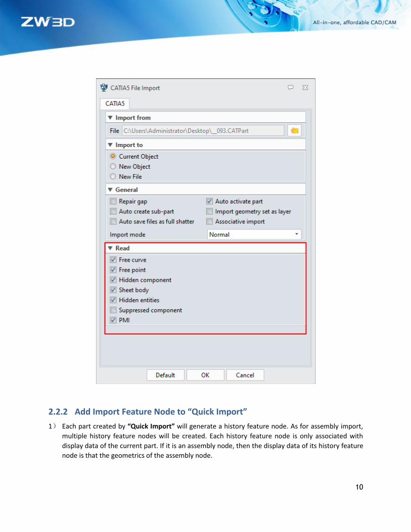
2.2 ★Adjustment to “Quick Import”
Optimize the file import efficiency of large 3rd format file. Increase the import efficiency from the
following two aspects and optimize user’s experience.
1) Introduce much more parallel mechanism to speed up the assembly drawing import.
2) Process import flow in the platform and optimize import flow.
The modified of import flow are as follows:
2.2.1 Adjustment to “Quick Import” UI
The new “Quick Import” cancels the limitation to user setting import mode. User can set some hidden
component, suppressed component and free point, etc.
10
2.2.2 Add Import Feature Node to “Quick Import”
1) Each part created by “Quick Import” will generate a history feature node. As for assembly import,
multiple history feature nodes will be created. Each history feature node is only associated with
display data of the current part. If it is an assembly node, then the display data of its history feature
node is that the geometrics of the assembly node.

11
2) Each history feature node records the contents including the imported optional setting, and the 3rd
format drawing path info that is corresponding to the current imported part.
3) User can redefine the history node created by “Quick Import” and can re-select the path of 3rd format
drawing while re-defining. According to the re-selected path, if the path is different as before, the
display data associated with the history feature node will be firstly cleaned, and then quickly re-
import the display data under the new path. If an assembly drawing is selected, only its geometrics
display data will be quickly imported.
4) In regeneration, use the current display data and it will not regenerate display data according to the
history node generated by “Quick Import” but skip the node directly.
5) Require adding a feather tag to the history feature node generated by “Quick Import”. History
regeneration will not be triggered by dragging the lightweight feature node.
6) The history node generated by “Quick Import” will increase “Load Model” command. If the
corresponding 3rd format file of the history node does not exist, it will delete the display data of the
history node accordingly. Meanwhile, load the corresponding geometrics data of the 3rd format and
convert the current history node to general static data node. If the 3rd format file does not exist, then
give a tip to user that the corresponding file cannot be found and terminate the loading model.
2.2.3 2nd Import Action in “Quick Import” (Import Real Geometric Data)
After “Quick Import”, what we get is only the display data not the real geometric data. Thus, after that,
we need to import the real geometric data. Such 2nd import action may happen in the following scenarios:
1) User requires initiatively to “Load Current Model” or “Load All Models”.
2) When user activates the corresponding part, prompt the user to load the real geometric data or not.
If the user selects Yes, then load the real geometric data.
2.2.4 Remove “Quick View”
Since the new “Quick Import” function is basically the same as the current "Quick View" function when
it is imported for the first time, the "Quick View" function is completely abandoned, and the relevant
options and command entries will be removed.
➔Where it is
File >> Import >> Quick Import

12
2.3 ★Convert Attributes Support
Support reading-in the user custom attribute of part while importing and reading-in the part attribute as
well as hidden components, suppressed components, hidden entities, user custom attributes and material
density. Formats and read functions are as below:
Format Hidden
Components
Suppressed
Components
Hidden
Entities
User Custom
Attributes(1)
Material
Density(2)
NX X √ √ √(3) √
Creo X √ X √ √
SolidWorks √ √ √ √(7) √
CatiaV5 √ √ √ √(4) √
Inventor X X X √(5) √
Solid Edge X X √ √(6) √
Remark: X means unable to be read; √ means able to be read.
(1). User custom attributes are only captured on the part, assembly, and component instead of the layer
of part internal shape.
(2). At present mater density can only acquire the material name and its corresponding density.
(3). NX user custom attribute name contains two parts: Category and Title. After converting ZW3D user
customer attribute, the attribute name shall be Category|Title
(4). Catia V5 supports acquiring the user custom attributes of assembly or sub-assembly (such as part
number and version and so on), but the user custom attributes of component is not supported (such as
instance name and so on).
(5). Inventor has limits to support the following user custom attributes: Support the attributes in the
options of Custom, Project and Status but excluding File Status of Status.
(6). SolidEdge supports user custom attributes started from ST4 while it is not supported in the older
versions.
(7). Solidworks has limits to support user custom attributes import. The information under Summary
option cannot be imported to ZW3D.
➔Where it is
File >> Import

13
2.4 Other Adjustment
2.4.1 DWG/DXF Export Add "Explode hatch as single line" Option
In 2D engineering environment, while exporting DWG/DXF format, section line is exported as the type
of pattern fill block. After checking the option of "Explode hatch as single line", the section line will be
exported to DWG/DXF file as the type of single line.

14
2.4.2 DWG/DXF Import Add “Placement” Field
While import DWG/DXF format to current object and current object is a part, add “Placement” field. The
drop-down list of “Placement” allows you to select all CSYS under current object. After importing, the
origin of the model aligns with the origin of the selected CSYS.

15
3 CAD
3.1 Sketch Design
3.1.1 Improvement of “Conflicting Constraints Check”
In sketch environment, when a conflict occurs to constraint/dimension, all conflicting constraints and
dimensions will list in Conflicting Constraints Manager where user can delete constraints/dimensions or
convert dimensions to reference dimensions. Newly add the pull-down list to filter display content,
including Show dimensions only, Show constraints only and Show all.
➔Where it is
Sketch Environment >> Constraint >> Conflicting Constraints
Configuration >> 2D >> Sketch >> Enable constraint conflicting manager
3.1.2 ★New “Equal Curvature”
In sketch environment, add “Equal Curvature” which can be added onto curve and curve, curve and arc,
curve, and line. The constraint lines need end to end. After constraint, two lines G2 continuity (curvature
equal).

16
➔Where it is
Sketch Environment >> Constraint >> Equal Curvature
3.1.3 New Character Spacing in ReadySketch Text
User can adjust the characters spacing through ReadySketch Text to better modify the value between
characters spacing.
➔Where it is
Sketch Environment >> Drawing >> ReadySketch Text >> Spacing

17
3.1.4 Support Relocate Sketch Plane, Sketch Direction and Sketch Origin in Sketch Editing
In sketch environment, add the function of “Relocate”, by which user can relocate sketch in the process
of sketch editing and does not need to exit from sketch at first.
➔Where it is
Sketch Environment >> Setting >> Relocate
3.1.5 ★New Cosmetic Sketch
In 3D sketch environment, newly add the function of “Cosmetic Sketch”, by which user can add some
symbols or graphic tags in part environment or draw some geometric figures onto other feature or
model (such as logo).

18
Three characteristics of “Cosmetic Sketch”:
1)Annotation: The sketch is an annotative sketch, which means it cannot be used in the features
of modeling.
2)Hatch pattern: After exiting “Cosmetic Sketch”, user can add hatch pattern in closed area in
“Cosmetic Sketch”.
3)Projected: The cosmetic sketch can be projected to the surface of entities and engineering
drawings.
➔Where it is
Part Environment >> Shape >> Basic Shape >> Cosmetic Sketch
3.1.6 Display tinted closed ring
1)Display tinted closed ring. During drawing, the general sketch can hatch closed area in entity
(pure color).
2)Closed area check. Prompt the user that exist nonstandard geometries to check closure when
he or she exits sketch in creating a sketch with modeling command.

19
➔Where it is
Sketch Environment >> DA Toolbars >> Closed Rings On/Off
3.1.7 New “2D Sketch Offset Constrain”
When the command is executing by sketch, add offset constraint by default. Analyst geometrics like line,
circle/arc, polyline, and rectangle and so on are supported. Display offset constraint icon and offset
distance dimensions between the original geometry and the offset geometry. Use can modify offset
distance through dimensions as well as delete offset constraints and dimensions.
➔Where it is
Sketch >> Curve >> Offset
3.1.8 New Option of “Hide used sketch”
Newly add the option of “Hide used sketch” to control whether the used sketch will be automatically
hidden.
➔Where it is
Configuration >> Display >> Toggle settings >> Hide used sketch

20
3.2 Wireframe Design
3.2.1 Improvement of “Project Curve”
Two mayor improvements of “Project Curve” include:
1) Break prior to project to curve and clean overlap after project to curve.
2) Solve failed situation of project to curve.
a) When the direction is not defined, the circle cannot be projected to sphere.
b) Issues related to project to seam edge.
c) Incorrect results of 2D sketch reference and offset.
3.2.2 Improvement of “Curve Modify” Align Type
Newly add 6 “Curve Modify” align types, including Auto Plan, Plane, WCS, View, Tangent and Normal as
follow:
Auto Plane: auto search the least square plane of control point in curve, and the control point moves in
the plane.
Plane: use custom defines input plane where the control point can move.
WCS: no limitation to the control point which can move to any point.
View: the control point can move in the current view.
Tangent: the control point moves upwards to the selected tangent line.
Normal: the control point moves upwards to the selected normal line.

21
➔Where it is
Part Environment >> Wireframe >> Edit Curve >> Modify
3.3 Part Design
3.3.1 ★Modeling Dimensional Accuracy Update
The minimum modeling accuracy is supported from 0.0001mm to 0.00001mm.
It is suggested that the maximum model accuracy is no more than modeling accuracy*10e+9 while the
minimum feature dimension is no less than modeling accuracy *10e-5.
3.3.2 ★Complete CSYS Support
Compose a complete Cartesian coordinate system, including Datum axis, Datum plane, Datum CSYS,
Datum axis 2D and add features in history according to the created timing sequence (sketch axis excluded).
The platform has only one local coordinate system (LCS) which is default as modeling reference system
with globally invariant world coordinate system (WCS) as its default value.
Replace XY, YZ, ZX features on history tree with a value of WCS Datum CSYS feature. It is only a general
Datum CSYS feature and does not present WCS or LCS. And it can also be redefined.

22
3.3.2.1 Datum Axis Datum axis only contains one orientation and defines origin and length. The datum axis command panel
shows as below:
Datum axis format includes Arrow and Line which can be set color, style and width.
Datum axis has the following characteristics:
1. Independent Entity

23
Datum axis is an independent entity and there is a single feature node in history tree. Support common
editing operations, including pattern, mirror, move and copy. It can be managed in layer manager and
has corresponding filter type DatumAxis.
2. Orientation Input
Execute such as Extrude, Pattern and Project Curves. As for the commands of vector\direction input in
the platform, the option of Datum Axis is added to filter with only allowing to select Datum axis object,
Datum plane object Z axis and Datum CSYS object has three datum axes. When the filter is Edge/Curve,
disallow to select all the above-mentioned objects.
3. Dimension PMI
Support Quick Dimension、Linear、Angular、Symmetry.
4. Assembly Constraints
1) Insert command: snap axis origin; coincide component origin and axis origin; component Z axis
orientation is identical with datum axis orientation.
2) Common constraint:parallel, vertical, angle, coincident。
➔Where it is
Part Environment >> Shape >> Datum >> Datum Axis
3.3.2.2 Datum axis 2D(Sketch)
The command panel is as follows: If “Construction geometry” is checked, create only internal axis to use;
otherwise, create external axis to use and work as sketch’s revolution axis by default.

24
2D datum axis is an infinite hidden line. The internal axis shares the same display attributes with the
general constructive line as grey hidden line. The external axis is brown hidden line. Use can switch the
internal and external axis through Toggle External/Internal.
2D Datum axis has the following characteristics:
1. Default XY
Sketch contains two XY objects by default, infinitely long, and default XY cannot be modified or
deleted.

25
2. Independent Entity
Support common editing operations, including Pattern, Mirror, Move, Copy and Revolve.
3. Constraint
Support 2D line constraint (excluding equal length and point to center).
4. Dimensions
Support 2D line dimensions.
5. Revolve axis

26
➔Where it is
Sketch Environment >> Sketch >> Drawing >> Axis
3.3.2.3 Datum CSYS
Datum CSYS is composed of origin, three X/Y/Z datum axes, and three datum planes. The origin is
something like a dot entity that plays as dot capture reference. The three datum axes can be treated as
an independent entity that used as general orientation reference. The three datum planes can be used as
a general plane. The coordinate system can be regarded as an independent entity.
The command panel goes as below:

27
Three datum axes, three datum planes and one origin are drawn in the drawing area. Each datum axis is
marked as its name (X, Y, Z). The coordinate system works as a whole selection by default, and its default
color is brown, which shows as below:
The datum CSYS has the following characteristics:
1. As an independent entity
Datum CSYS exists as an independent object and corresponds to an independent modeling history tree,
which can be executed by common edit commands such as Pattern, Mirror, Move and Copy. There exits
corresponding Datum CSYS filter object. It can be treated as an independent object as well as managed
by layer manager. Besides, it has unique attributes such as visibility, color and line thickness, etc.

28
2. Component members
It is composed by origin, X/Y/Z datum axes and three datum planes.
3. Constraints
The coordinate system aligns with CSYS.
➔Where it is
Part Environment >> Shape >> Datum >> Datum CSYS
Newly add option “CSYS” in Default datums of Configuration and set “CSYS” as default datum. After
setting, the default “CSYS” is created when a new part is created. Keep the original “Triad” option, you
can still switch to the old “Triad” mode through this option.
➔Where it is
Configuration >> Part >> General >> Default datums
3.3.3 New Method to Create Datum Plane
Create a datum plane with 2 entities. Newly add the two following entities to select.
1) Select arc surface and datum plane to create plane. 2) Select datum plane and line to create plane.
➔Where it is
Part Environment >> Shape >> Datum >> Datum Plane >> 2 Entities
3.3.4 Geometries Direct Cross File Copy via "Ctrl+C/Ctrl+V" Support
Newly add hotkey "Ctrl+C/Ctrl+V" to copy geometries (Curves, Surface, Entity). The copied geometries will
be pasted as static ones.
29
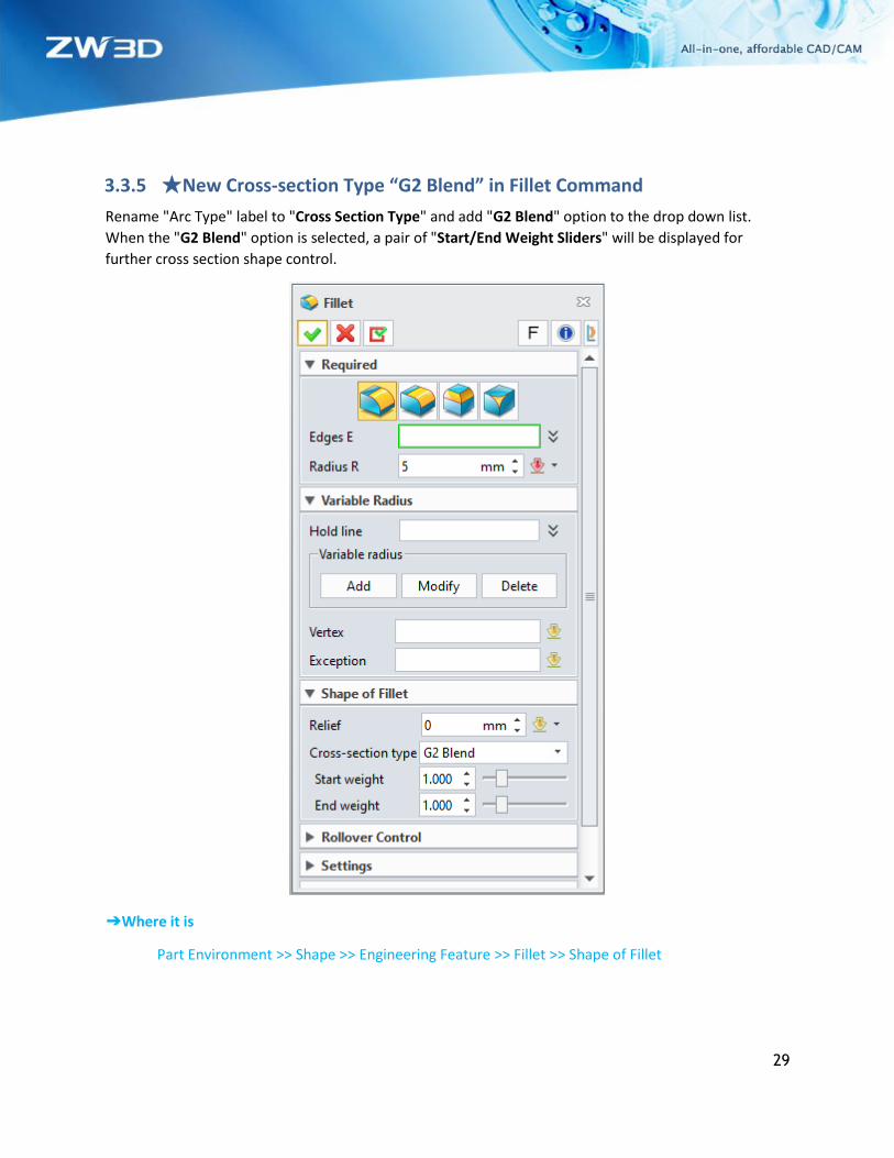
3.3.5 ★New Cross-section Type “G2 Blend” in Fillet Command
Rename "Arc Type" label to "Cross Section Type" and add "G2 Blend" option to the drop down list.
When the "G2 Blend" option is selected, a pair of "Start/End Weight Sliders" will be displayed for
further cross section shape control.
➔Where it is
Part Environment >> Shape >> Engineering Feature >> Fillet >> Shape of Fillet

30
3.4 Free Form Design
3.4.1 New “Cross Trim”
Add a new command Cross Trim in Free Form Ribbon, by which user can decide which side to keep when
to select more than two sheets or faces and select whether to automatically sew the remaining or not.
➔Where it is
Part Environment>> Free Form >> Edit Face >> Cross Trim
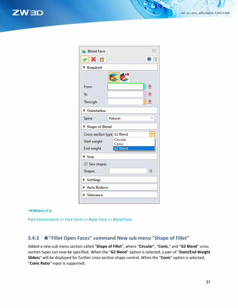
3.4.2 ★"Blend Face" Command New Option "G2 Blend"
Renamed "Arc Type" label to "Cross Section Type" and added "G2 Blend" option to the drop down list.
When the "G2 Blend" option is selected, a pair of "Start/End Weight Sliders" will be displayed for
further cross section shape control.
31
➔Where it is
Part Environment >> Free Form >> Basic Face >> Blend Face
3.4.3 ★"Fillet Open Faces" command New sub menu "Shape of Fillet"
Added a new sub menu section called "Shape of Fillet", where "Circular", "Conic," and "G2 Blend" cross
section types can now be specified. When the "G2 Blend" option is selected, a pair of "Start/End Weight
Sliders" will be displayed for further cross section shape control. When the "Conic" option is selected,
"Conic Ratio" input is supported.

32
➔Where it is
Part Environment >> Free Form >> Edit Face >> Fillet Open Faces
3.5 Sheet Metal Design
3.5.1 ★New “Zero Radius Flange”
This function aims at supporting zero radius flange, including its construction, modification, folding and
unfolding, and identification import. Add zero radius flange to six commands including Full Flange, Flange
with Profile, Partial Flange, Hem Flange, Fold by Line and Jog. As for the bend radius less than modeling
accuracy, all will convert to zero radius flange.

33
3.5.2 Improvement of “Punch”
Once “Punch” is interacted with punch mental plane, punch will be completed. Support “Punch” to select
face excluded for forming open.
Support external part model as “Punch”. Location is provided to locate related modeling. Related with
source is to control whether there are relations and decides to update punch result as external “Punch”
model updates. Add “Punch” library to the platform standard library, which allows user to build own
“punch” library.
The command panel goes as below:

34
➔ Where it is
Part Environment >> Sheet Metal >> Form >> Punch

35
3.6 ECAD
Check the option of “One object per file (new files)” in General of Configuration in advance.
➔ Where it is
Part Environment >> Configuration >> General >> One object per file (new files)
3.6.1 Import IDF File
3.6.1.1 New “Import IDF File” The import steps go as below: click “File >Import>Import…”, and the following dialogue will pop up
after selecting required file to import. After setting the import options, click “OK” to import IDF file.
➔Where it is
File >> Import >> Import…

36
3.6.2 Export IDF File
3.6.2.1 New “Export IDF File in ECAD Environment” The export steps are as following: click “File>Export>Export…”, and then the following dialogue will
pop up and click “OK” to export IDF file after setting the board file, library file and export version, etc.
➔Where it is
File >> Export >> Export…
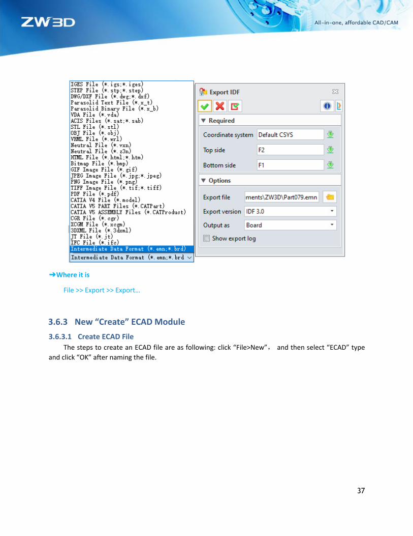
3.6.2.2 New “Export IDF in Part Environment” The export steps are as below: click “File>Export>Export…”, and the following dialogue will pop up
and click “OK” or “Apply” to export the corresponding file after settings.
37
➔Where it is
File >> Export >> Export…
3.6.3 New “Create” ECAD Module
3.6.3.1 Create ECAD File
The steps to create an ECAD file are as following: click “File>New”, and then select “ECAD” type
and click “OK” after naming the file.

38
➔ Where it is
File >> New >> ECAD
3.6.3.2 New/Edit Board
Click is used to create a new PCB model or edit an existing PCB model.
The steps to create are as following: click “New/Edit board”, and then the following dialogue will
pop up. Click “OK” after naming the file.

39
➔ Where it is
ECAD Environment >> Assembly >> Component >> New/Edit Board
3.6.3.3 Region Set Use “Region Set” to set cosmetic sketch as a region with specified attributes, where user can define
“Routing Region”, “Placement Region”, “Via Region”, “Other Region” and “Placement group region”.
• Routing region: set a closed profile cosmetic sketch as a routing region which can be set to
allow/disallow routing region.
• Placement region: set a closed profile cosmetic sketch as a region that allow/disallow to place.
• Via Region: set a closed profile cosmetic sketch as Via region.
• Other region: set a closed profile cosmetic sketch as other region which is namely user custom region.
40
• Placement group region:set closed profile cosmetic sketch as a placement group region.
➔ Where it is
ECAD Environment >> ECAD Board >> Engineering Feature >> Region Set
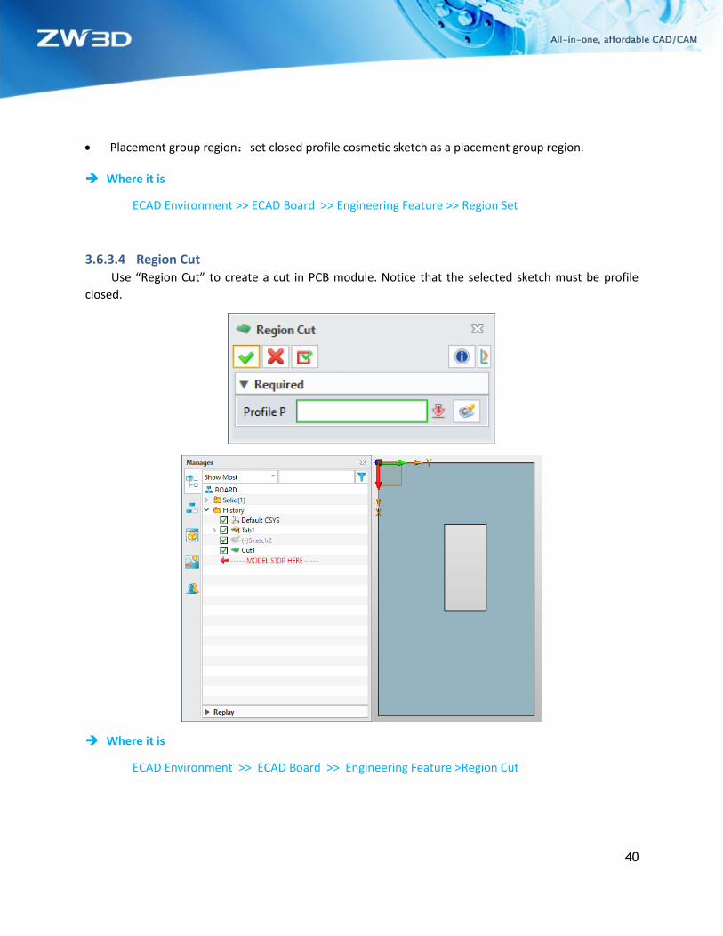
3.6.3.4 Region Cut Use “Region Cut” to create a cut in PCB module. Notice that the selected sketch must be profile
closed.
➔ Where it is
ECAD Environment >> ECAD Board >> Engineering Feature >Region Cut
41
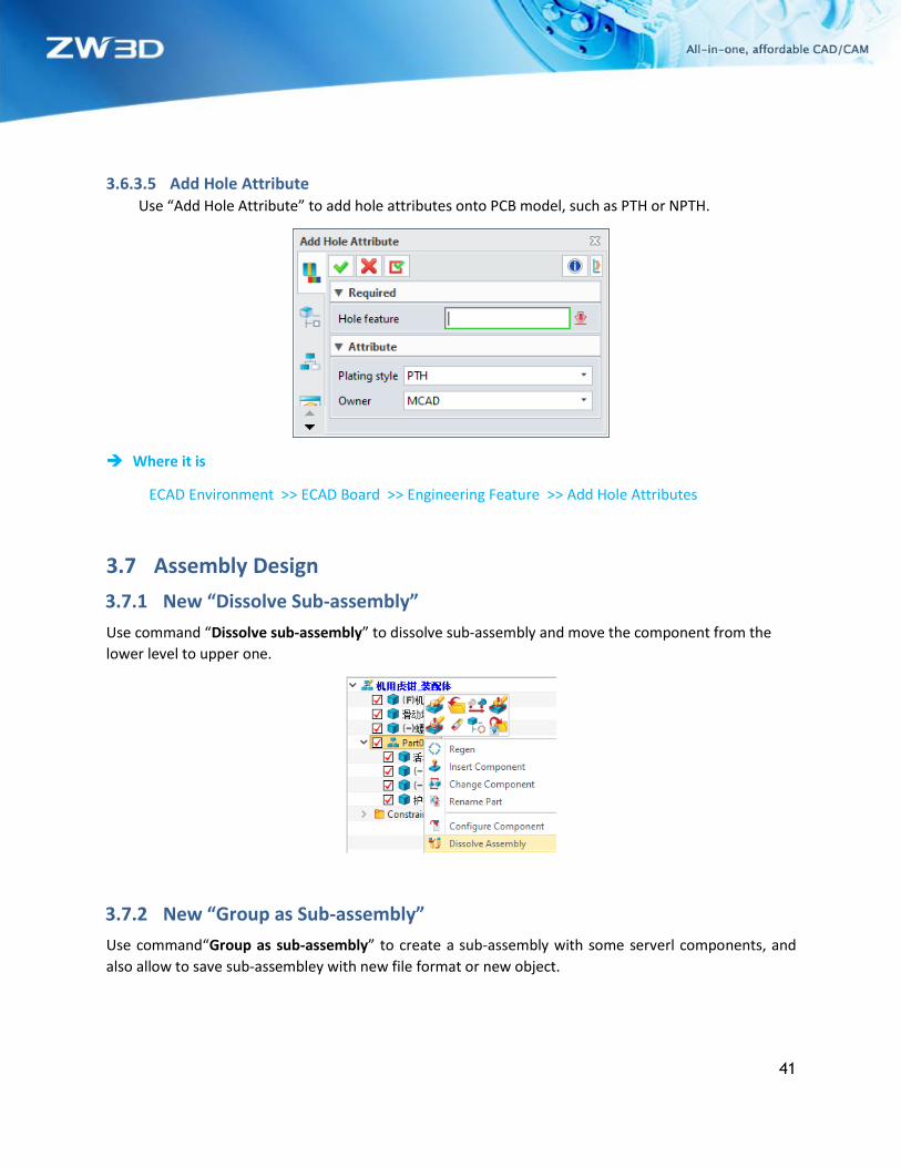
3.6.3.5 Add Hole Attribute Use “Add Hole Attribute” to add hole attributes onto PCB model, such as PTH or NPTH.
➔ Where it is
ECAD Environment >> ECAD Board >> Engineering Feature >> Add Hole Attributes
3.7 Assembly Design
3.7.1 New “Dissolve Sub-assembly”
Use command “Dissolve sub-assembly” to dissolve sub-assembly and move the component from the
lower level to upper one.
3.7.2 New “Group as Sub-assembly”
Use command“Group as sub-assembly” to create a sub-assembly with some serverl components, and
also allow to save sub-assembley with new file format or new object.

42
3.7.3 “Edit Constraint” Support Multi-select Components and Search Mutual Constraints
Add a new “Edit Constraint” to support multiple components selected and search their mutual
constraints.
➔ Where it is
Part Environment >> Assembly >> Constraint >> Edit Constrains

43
3.7.4 New “Filter” in Assembly Tree
Add a filter button in search box of manager to control the show result.
3.7.5 ★New “Clearance Check”
Provide new assembly search command “Clearance Check” with the following characteristics:
1) Support for searching clearance value between components;
2) Support for searching clearance value between component and shape;
3) “Clearance Check” result displays in a table;
4) To export “Clearance Check” result in xlsx file is supported.
➔Where it is
Part Environment >> Assembly >> Inquire >> Clearance Check

44
3.7.6 ★New “Batch Attribute Edit”
Add a new command “Batch Attribute Edit” to provide user to batch edit part attributes. The command
panel goes as below; its left list shows the attributes and values while its right list shows the objects to
edit. User can modify multiple attributes of multiple components at one time.
The left list supports to import via external template, and the command will read the template’s attribute
and value. User can edit template file. Support select a component through Input Format button and take
the component’s attribute value as default value. Support Synchronous modification of attributes like
material, density, part size and stock size, etc.
The right component list supports user to select part and filter to select parts.
➔Where it is
Part Environment >> Tools >> Attributes >> Batch Attribute Edit
45
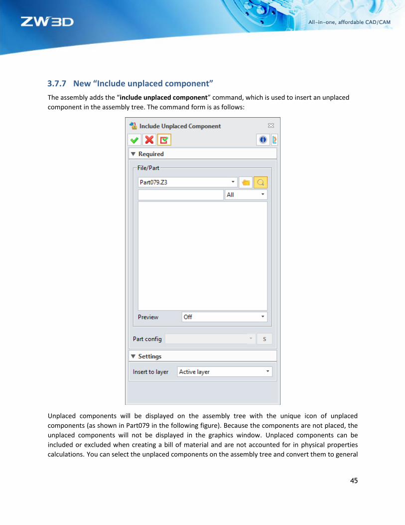
3.7.7 New “Include unplaced component”
The assembly adds the “include unplaced component” command, which is used to insert an unplaced
component in the assembly tree. The command form is as follows:
Unplaced components will be displayed on the assembly tree with the unique icon of unplaced
components (as shown in Part079 in the following figure). Because the components are not placed, the
unplaced components will not be displayed in the graphics window. Unplaced components can be
included or excluded when creating a bill of material and are not accounted for in physical properties
calculations. You can select the unplaced components on the assembly tree and convert them to general

46
components through the right-click menu “Insert Component”. After the components is converted to
general components, it cannot be converted back to unplaced components.
➔Where it is
Part Environment >> Assembly >> Component >> Include Unplaced Component
3.8 Drafting Design
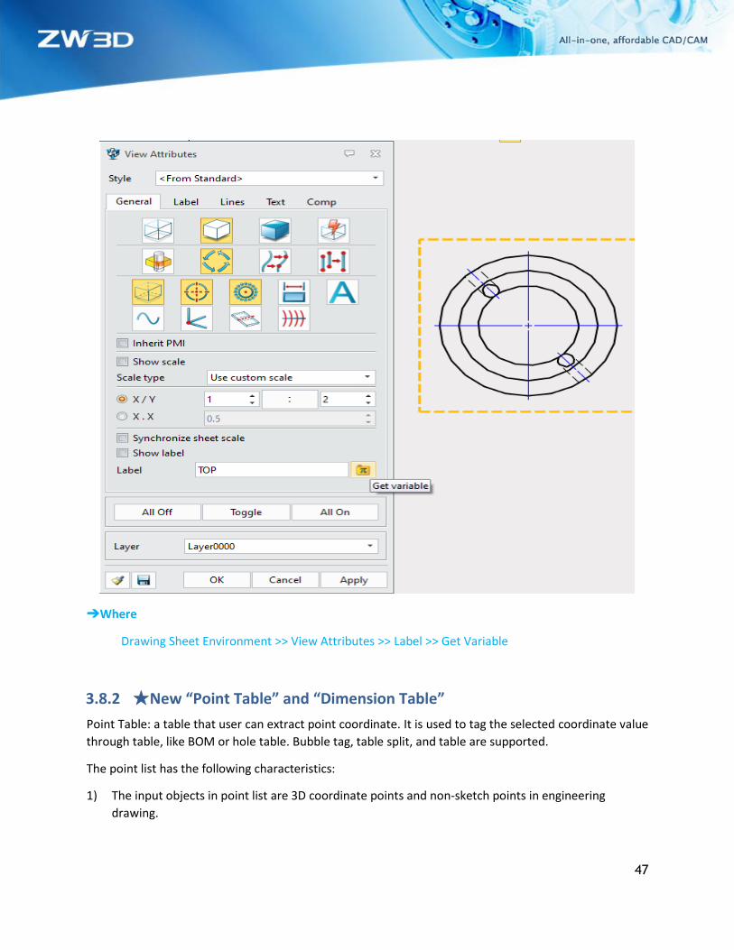
3.8.1 Variable Input in Engineering Drawing Show Label Support
Add a new variable input in engineering drawing show label.
47
➔Where
Drawing Sheet Environment >> View Attributes >> Label >> Get Variable
3.8.2 ★New “Point Table” and “Dimension Table”
Point Table: a table that user can extract point coordinate. It is used to tag the selected coordinate value
through table, like BOM or hole table. Bubble tag, table split, and table are supported.
The point list has the following characteristics:
1) The input objects in point list are 3D coordinate points and non-sketch points in engineering
drawing.

48
2) Extracting points in both 2D and 3D coordinates is supported.
3) When the selected point contains point of view, default 3D coordinate origin as reference point.
When the selected point does not contain point of view, default 2D drawing origin as reference point.
4) When the selected point contains point of view, the reference point and point of view will move as
view moves; otherwise, it will not.
5) When the point list contains different point of view, the default reference point will generate order
according to view in priority.
6) Be similar with BOM or hole table. Bubble tag, split table and table style are supported.

49
Dimension table: mark number and list table to the dimensions in drawing according to order.
The dimension table has the following characteristics:
1) Dimensions in table contain all dimension content, including symbols such as radius R, angle °,
thread M and depth, etc. It is not only a number.
2) Dimension id will move as view and dimension move.
3) Dimension is associative with table. When the dimensions change, the table will update as along.

50
4) When one dimension is lost, the dimensions will change in red and the corresponding row in the
table will remain.
➔Where it is
Drawing Sheet Environment >> Layout >> Table >> Annotation

51
3.8.3 New Insert “OLE Object”
Add a new “OLE Object” to drafting environment and support insert “OLE” object to drafting.
➔Where it is
Drawing Sheet Environment >> Dimension >> Symbol >> OLE Object
3.8.4 New 2D BOM Default Template Setting in Configuration
Add a 2D BOM default template setting in configuration and configure 2D BOM template through this
filed. Default create this template when to create 2D BOM.
➔Where it is
Configuration >> Files >> Drafting >> BOM template

52
3.9 ZWMold
3.9.1 “Trim Pin” Support to Select Multiple Components as Trim Body
Add a new “Trim Pin” to support select multiple parts as trim body.
➔Where it is
Part Environment >> Mold >> Library >> Trim Pin
53
4 CAM
4.1 ★Enhancements of Full Machine Simulation
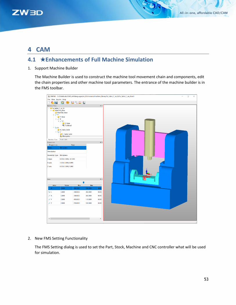
1. Support Machine Builder
The Machine Builder is used to construct the machine tool movement chain and components, edit
the chain properties and other machine tool parameters. The entrance of the machine builder is in
the FMS toolbar.
2. New FMS Setting Functionality
The FMS Setting dialog is used to set the Part, Stock, Machine and CNC controller what will be used
for simulation.

54
3. New Fanuc CNC Controller
New the Fanuc CNC controller to interpret the NC file which output from Fanuc post processor. The
current version only supports Fanuc controller.
4. Support RTCP Functionality
In ZW3D 2021, we support the RTCP functionality in FMS, if the real machine tool has RTCP function,
please turn on the RTCP option in FMS during simulation. If the real machine tool does not have
RTCP function, please turn off the RTCP option and configure the .znc file for machine simulation.
55
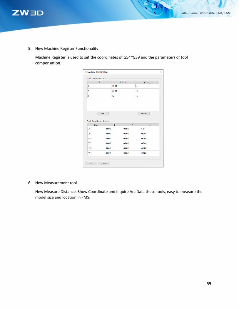
5. New Machine Register Functionality
Machine Register is used to set the coordinates of G54~G59 and the parameters of tool
compensation.
6. New Measurement tool
New Measure Distance, Show Coordinate and Inquire Arc Data these tools, easy to measure the
model size and location in FMS.

56
7. Support the Tool Compensation Function
FMS can simulate the tool path with tool compensation, user needs to set related parameters in the
Machine Register.
8. New the Simulation Speed Functionality
Simulation Speed functionality is used to control the simulation speed, the right side of the control
bar speeds up the simulation.
57
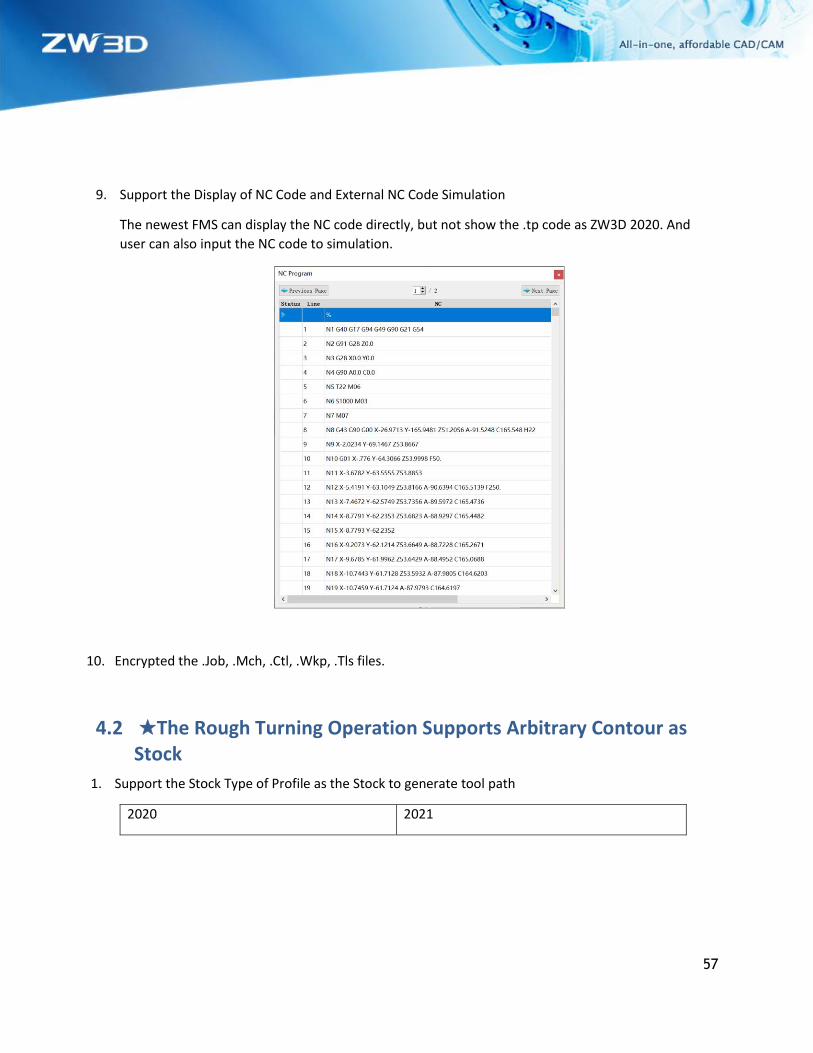
9. Support the Display of NC Code and External NC Code Simulation
The newest FMS can display the NC code directly, but not show the .tp code as ZW3D 2020. And
user can also input the NC code to simulation.
10. Encrypted the .Job, .Mch, .Ctl, .Wkp, .Tls files.
4.2 ★The Rough Turning Operation Supports Arbitrary Contour as Stock
1. Support the Stock Type of Profile as the Stock to generate tool path
2020 2021

58
2. Support the Stock Type of Workpiece to generate tool path
2020 2021
4.3 New Arc Fitting Functionality in 2X Operation
2X operations added the Fit Arc option; the generated tool path will be as close to the arc as possible
according to the parameters set.

59
Chord Tolerance --Determines the accuracy of the arc
Max Radius -- Determine the max radius of the output G02/G03, if the radius of the fitted arc is greater
than Max Radius, G01 will be output.
4.4 ★New Arc Fitting Functionality in Surface Engraving Operation and 5X Operations
In the past, the Surface Engraving and 5X operations can only output linear tool path, after added this Fit
Arc option, the generated tool path of surface engraving operation will be as close to the arc as possible.
And the 5x operations will output the arc in the XY, XZ, YZ planes of the coordinate of the operation.
4.5 New Regular Pentagon, Hexagon and Octagon Turning Tools
New Regular Pentagon, Hexagon and Octagon Turning Tools support rough, finishing and facing
operations.
Pentagon Tool Hexagon Tool Octagon Tool

60
4.6 ★New Excel Format of Operation List
1. Support for output operation list in Excel format
In ZW3D 2021, the operation list can be output in Excel format, user can customize the Excel
template as needed.

61
2. Support for show or hide the default coordinate
User can show or hide the default coordinate as needed; this determines whether it will be
displayed on the view of operation list.
3. Support the output view of the specified coordinate system

62
User can specify the coordinate system by Set/Cancel Active option of frame, then operation list will
output the view according to the active coordinate system.
4. Increased output speed
Output the Excel format is faster than the Html format about half the time.
4.7 Independent the Web Editor Program of the Zw3D Post
In ZW3D 2021, user can web edit the .znc file on the independent the web editor, no longer dependent
on Internet explorer and the port 8088.

63
4.8 New Tool Path Verification Progress Bar
New the progress bar in tool path verification, user can realize the simulation of drag and drop mode,
which is easy to find the problem of tool path.
4.9 Support the Left to Right Cutting Direction in Groove operation
In ZW3D 2021, The Groove operation can cut from left to right.

64
4.10 ★Support the G68.2 Functionality
In ZW3D 2021, we support the G68.2 functionality; user can call corresponding function in
ZW_FANUC_5X.znc, ZW_SINUMERIK_5X.znc and ZW_HEIDENHANIN_5X.znc files.
4.11 New Limit Stepover Option in QM Roughing Operations
In QM Roughing Operations, we added a Limit Stepover option to restrict whether user can set big
stepover. The default setting of Limit Stepover is “Yes”, which means that the user cannot set the stepover
more than 90% tool flat diameter. If set to “No”, that user can set big stepover.
65
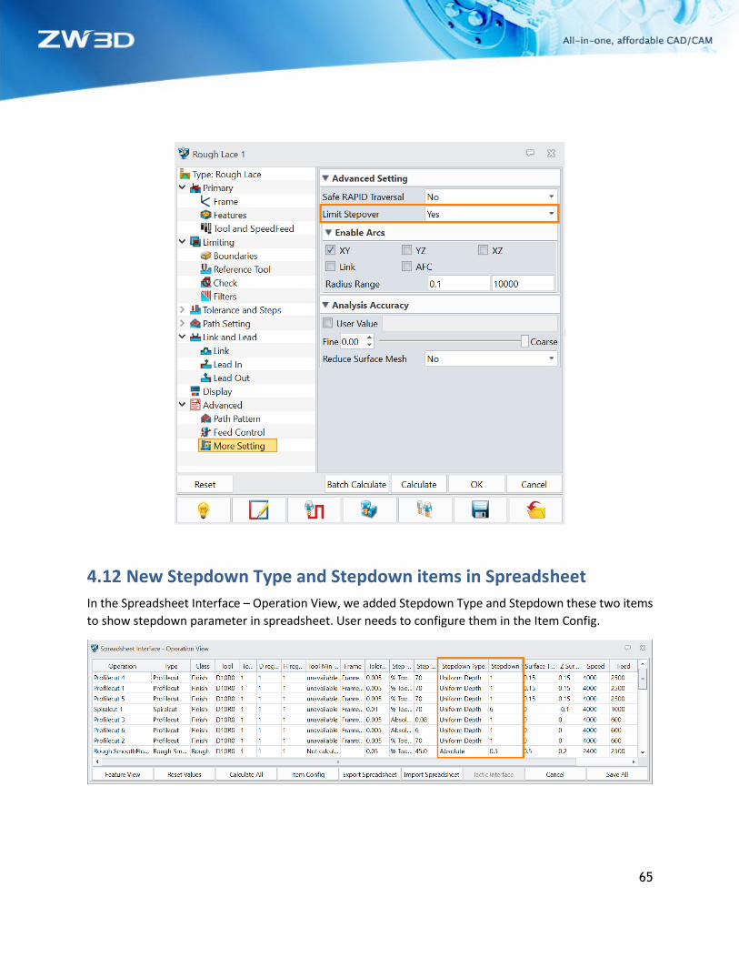
4.12 New Stepdown Type and Stepdown items in Spreadsheet
In the Spreadsheet Interface – Operation View, we added Stepdown Type and Stepdown these two items
to show stepdown parameter in spreadsheet. User needs to configure them in the Item Config.

66
4.13 Distinguish the Type of Input Value for the Speed Feed Table
In ZW3D 2021, user can select the type of input value in the speed feed table. It can be selected to
Percent or Numeric in Speeds table, and selected Percent, Rapid or Numeric in Feed rates table.