zw3d what’s new - zwsoftdl.zwsoft.com/zw3d/pc/zw3d/tech/productrelease/zw3d2018/what… · 3.3.1...
TRANSCRIPT
ZW3D WHAT’S NEW V 2018
ZW3D Software Co., Ltd

2
Copyright and Trademarks © Copyright 2017 ZWCAD Software Co., Ltd. All rights reserved. 32/F Pearl River Tower, No.15 Zhujiang West Road, Tianhe District, Guangzhou 510623, P.R.China (8620)38289780
ZW3D™ V2018 What’s New This documentation may be reproduced provided it complies with the terms presented on the LICENSE AGREEMENT supplied. ZWCAD Software Co., Ltd and the program authors have no liability to the purchaser or any other entity, with respect to any liability, loss, or damage caused, directly or indirectly by this software and training materials, including but not limited to, any interruptions of service, loss of business, anticipatory profits, or consequential damages resulting from the use of or operation of this software. Updates may be made to this documentation and incorporated into later editions. ZW3D™ is a registering trademark of ZWCAD Software Co., Ltd. The ZW3D™ logo is a registering trademark of ZWCAD Software Co., Ltd. ZWCAD™, ZWSOFT™, the ZWCAD™ logo, and the ZWSOFT™ logo are all trademarks of ZWCAD Software Co., Ltd. Printed in the P. R. China.
I
Contents
Highlights of ZW3D 2018 ................................................................................... 1
1 Basic ..................................................................................................... 1
1.1 ★UI & Work flow Changes ................................................................. 1
1.1.1 Unit Shown on Command Form ........................................................... 1
1.1.2 New Field Color and Highlight ............................................................ 2
1.1.3 More Direct Drag Behaviors ................................................................ 3
1.1.4 Tweaked Display ............................................................................ 5
1.2 ★Enhanced Equation Manager ............................................................ 6
1.3 ★Strengthened “View Dynamic Section” ................................................ 9
1.4 More Inquire Functionalities .............................................................. 11
1.4.1 New Independent “Radius” Measurement .............................................. 11
1.4.2 Enhanced “Distance” Measure ........................................................... 12
1.4.3 New “Bounding” Inquiry .................................................................. 14
1.4.4 Other Changes in Inquire ................................................................. 15
1.5 ★More PMI Objects ........................................................................ 16
1.6 ★Enhanced Layer Manager ............................................................... 20
1.7 New “Visibility Manager” ................................................................. 22
1.8 ★New “File Browser” ..................................................................... 23
1.9 New “SHX Converter” ..................................................................... 24
1.10 Tweaked License Manager ................................................................ 25
2 Translator ............................................................................................. 26
2.1 Import ....................................................................................... 26
2.1.1 ★New “Associative Import” .............................................................. 26
II
2.1.2 ★New Parallel Assembly Import ......................................................... 27
2.1.3 ★New “Multi-import” ..................................................................... 28
2.1.4 Enhancements for Import ................................................................. 29
2.1.5 Import Format Update .................................................................... 30
2.2 Export ........................................................................................ 31
2.2.1 ★More Objects Involved in PDF Export ................................................. 31
2.2.2 New “Remove text font info” in DWG Export .......................................... 32
3 CAD ..................................................................................................... 33
3.1 Sketch Design ............................................................................... 33
3.2 Wireframe Design .......................................................................... 36
3.3 Part Design .................................................................................. 37
3.3.1 ★Updated Part Attribute ................................................................. 37
3.3.2 ★Expanded “Config Table” ............................................................... 41
3.3.3 ★Upgraded “Shell” ........................................................................ 48
3.3.4 More Robust “Direct Edit” ................................................................ 50
3.3.5 New “Dim Move Face”..................................................................... 51
3.3.6 ★Strengthened “DE Move” ............................................................... 52
3.3.7 ★Enhanced “Replace Face” .............................................................. 53
3.3.8 Improved “Modified Fillet” ............................................................... 53
3.3.9 Expanded “Minimize surface data” ...................................................... 55
3.3.10 Tweaked Extension and Offset for Surface of Revolution ............................ 55
3.3.11 Changes in “Stock” ........................................................................ 56
3.3.12 New “Copy/Move to Layer” .............................................................. 57
3.3.13 New “Fix Primitive Faces” ................................................................ 58
3.3.14 Misc. ......................................................................................... 58
III
3.4 Assembly Design ............................................................................ 60
3.5 Renewed Part Lib Design Tools .......................................................... 63
3.5.1 ★Renewed “Part Table” .................................................................. 63
3.5.2 ★New “Reuse Lib” ......................................................................... 69
3.5.3 ★New “ Add Reusable Part” ............................................................. 71
3.5.4 New MISUMI Lib Support .................................................................. 73
3.6 ZWMold Design ............................................................................. 74
3.7 Drafting Design ............................................................................. 75
3.7.1 ★New “Sketch” in Drafting Context .................................................... 75
3.7.2 ★Updated “Text” .......................................................................... 77
3.7.3 Variable Support for Tolerance .......................................................... 79
3.7.4 ★Strengthened “BOM” .................................................................... 80
3.7.5 Other Changes in Drafting ................................................................ 81
4 CAM ..................................................................................................... 83
4.1 Summary of CAM New Features .......................................................... 83
4.2 Shape Modify Function in Surface Feature ............................................. 84
4.3 5-Axis Point Control and 3X to 5X Undercut in Z Level and Offset 3D ........... 85
4.3.1 5-Axis Point Control ....................................................................... 85
4.3.2 3X to 5X Undercut.......................................................................... 86
4.4 Along Tool Axis in Plane Cut and Guide Surface ISO Cut ........................... 87
4.5 Side Step Function in 5X Side Cut Operation ........................................ 87
4.6 Frame Option in Flat Finish Operation .................................................. 88
4.7 Misc. – some enhancements to users’ work more efficient and more stable ...... 89
4.7.1 Total Time Function in Setup ............................................................ 89
4.7.2 Z Min, Z Max and Total Time Entries in Spreadsheet Interface – Operation View 89

IV
4.7.3 Frame Attribute in Frame Function ..................................................... 90
4.7.4 Frame Option in Flat Region Feature ................................................... 90
4.7.5 “SHX Converter” used in CAM ............................................................ 91
4.7.6 Chamfer Cut Supports the Containment Surface ...................................... 92
1
Highlights of ZW3D 2018
Basics: Improved UI & Work flow
Enhanced Equation Manager
Strengthened “View Dynamic Section”
More PMI objects
Enhanced Layer Manager
Translator: New “Associative Import”
New Parallel Assembly Import
New Multi-import
More Objects Involved in PDF Export
CAD: Updated Part Attribute
Expanded “Config Table”
Upgraded “Shell”
Strengthened “DE Move”
Enhanced “Replace Face”
Renewed “Part Table”
New “Reuse Lib”
Renewed “Add Reusable Part”
New “Sketch” in Drafting Context
Updated “Text”
Strengthened “BOM”
CAM: 5-Axis Point Control and 3X to 5X Undercut in Z Level and Offset 3D
Along Tool Axis in Plane Cut and Guide Surface ISO Cut
Side Step Function in 5X Side Cut Operation
Note: Important enhancements in this article are marked with
1
1 Basic
1.1 ★UI & Work flow Changes
1.1.1 Unit Shown on Command Form
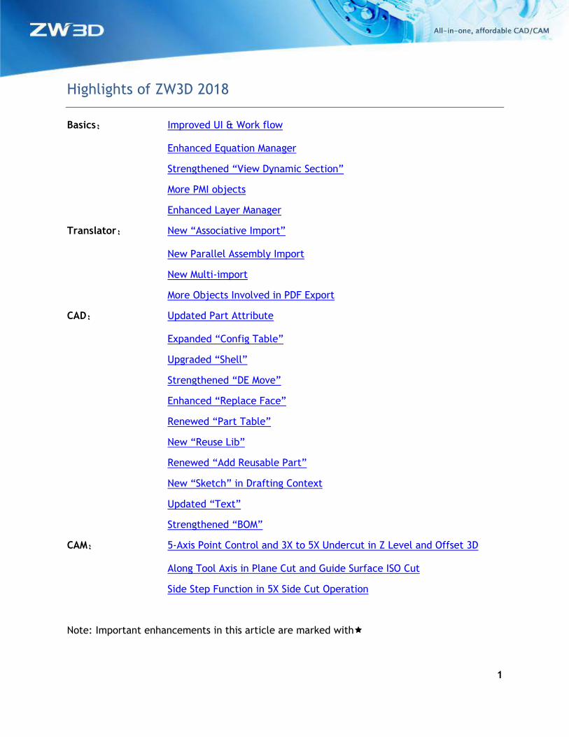
Unit is shown on the command form to allow users to learn about what unit is used for the active command, avoiding the misinput due to the inconsistence between the command unit and the part unit. 1. Direct active unit reveal to guide users
2. Record the feature unit during its
creation avoiding model changing when part unit is switched.
3. Unit shown on feature redefinition is the
one used on its creation.
4. Numeric field can only refer to the variable with the same dimension to avoiding the confused conversion among different dimensions. For example, the Length on the left can’t be assigned by a variable A = 10 kg for their dimensions are not the same.
5. When a constant field is assigned by a variable with a unit, the variable will be converted into current part unit first, then assigned.
6. Point field can refer to a point variable like the Twist point field on the left.
7. Vector field can refer to a vector
variable like the Direction field on the left.
2
1.1.2 New Field Color and Highlight
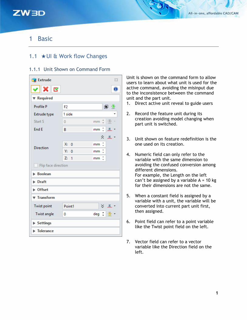
1. New entity field color to distinguish each other
When a command form has several different entities input fields, the field color will be
added to each field so that they can distinguish each other.
2. Wireframe highlight on inactive shape entity field
When a shape entity field on an active form is not active, the shape will only highlight its
edges to indicate itself.
3
1.1.3 More Direct Drag Behaviors
This version provides more draggable handles and behaviors, so users can finish their work
within the graphic area. Here are the details:
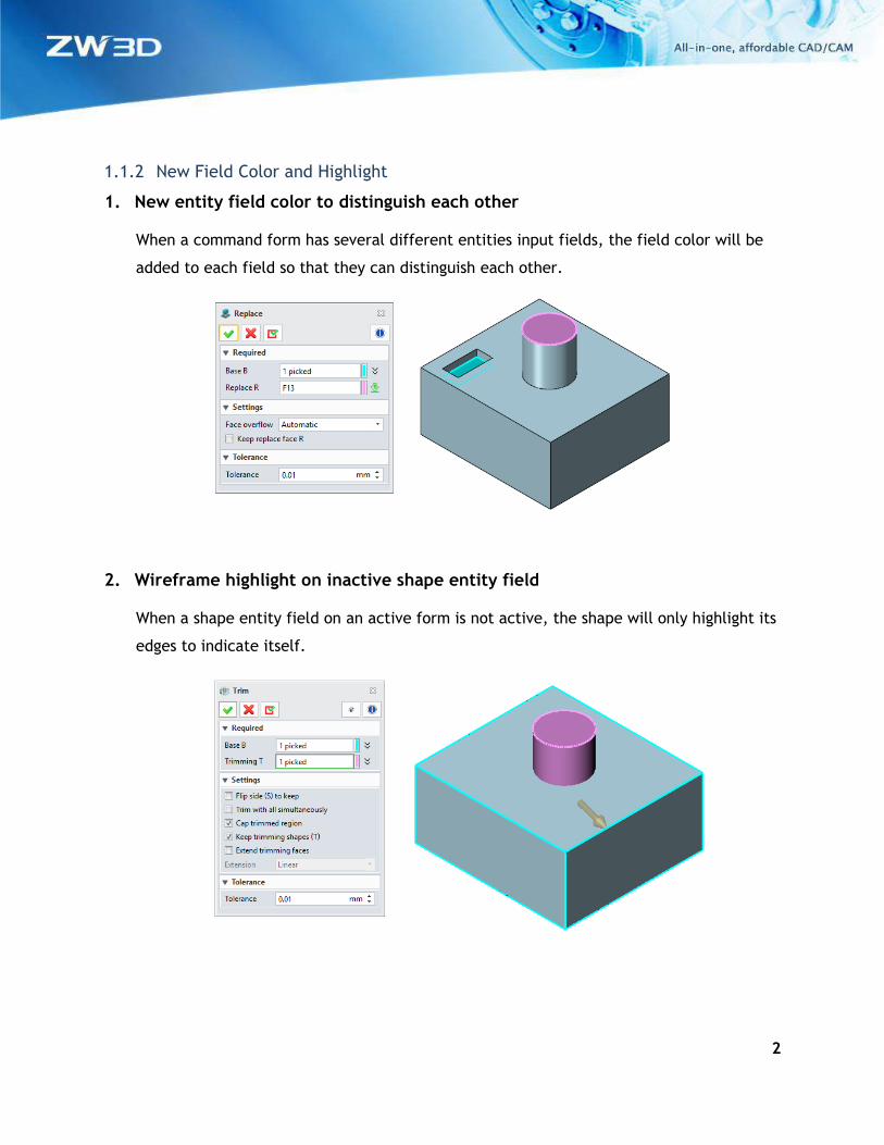
1. Direct movable point
Besides using the Edit option form the right-click menu, users can directly drag the input
point inside graphic area to modify its position.
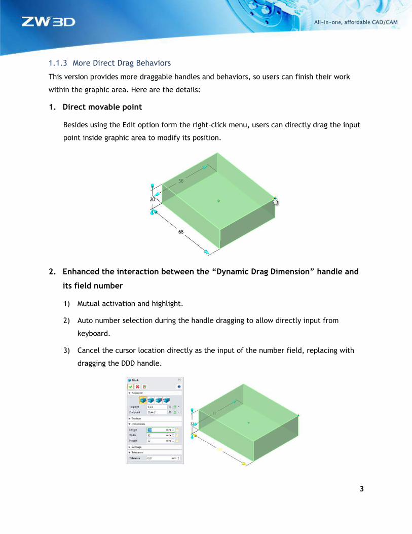
2. Enhanced the interaction between the “Dynamic Drag Dimension” handle and
its field number
1) Mutual activation and highlight.
2) Auto number selection during the handle dragging to allow directly input from
keyboard.
3) Cancel the cursor location directly as the input of the number field, replacing with
dragging the DDD handle.
4
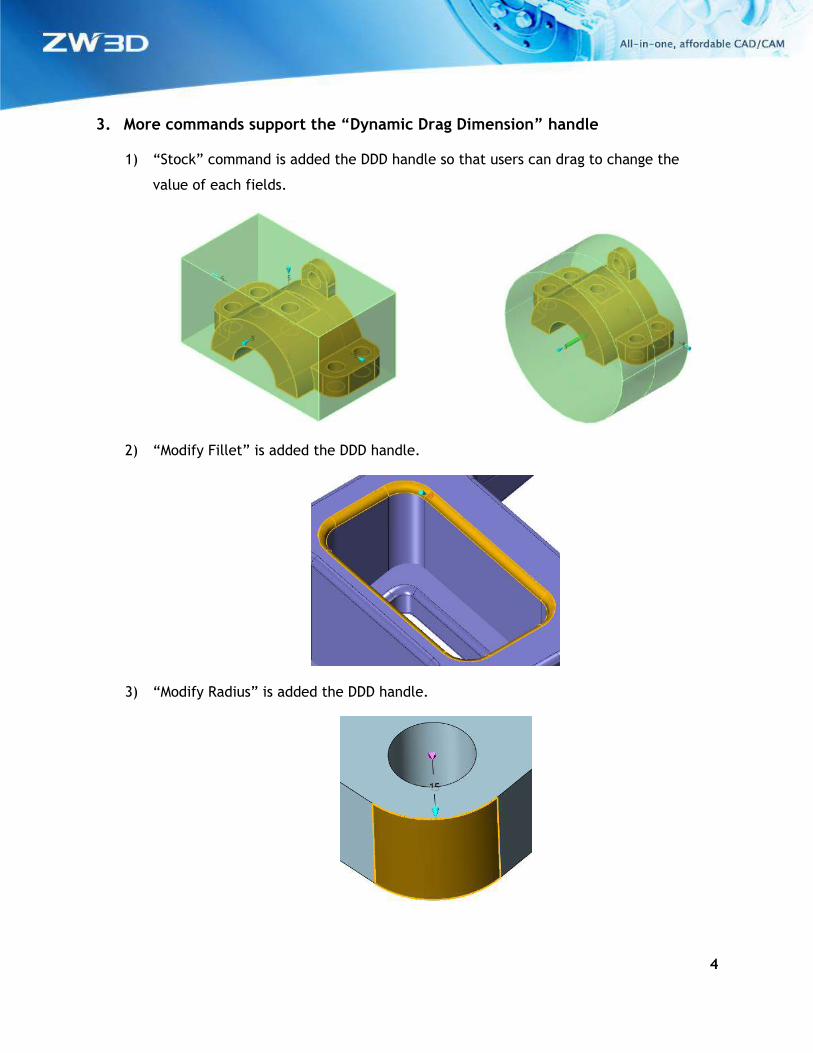
3. More commands support the “Dynamic Drag Dimension” handle
1) “Stock” command is added the DDD handle so that users can drag to change the
value of each fields.
2) “Modify Fillet” is added the DDD handle.
3) “Modify Radius” is added the DDD handle.
5
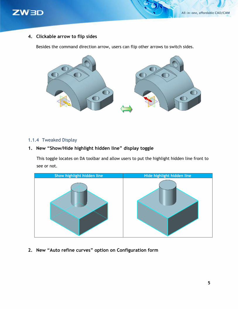
4. Clickable arrow to flip sides
Besides the command direction arrow, users can flip other arrows to switch sides.
1.1.4 Tweaked Display
1. New “Show/Hide highlight hidden line” display toggle
This toggle locates on DA toolbar and allow users to put the highlight hidden line front to
see or not.
Show highlight hidden line Hide highlight hidden line
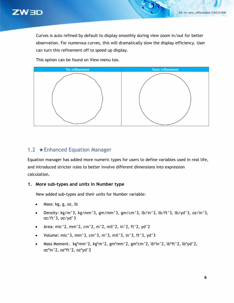
2. New “Auto refine curves” option on Configuration form
6
Curves is auto refined by default to display smoothly during view zoom in/out for better
observation. For numerous curves, this will dramatically slow the display efficiency. User
can turn this refinement off to speed up display.
This option can be found on View menu too.
No refinement Auto refinement
1.2 ★Enhanced Equation Manager
Equation manager has added more numeric types for users to define variables used in real life,
and introduced stricter rules to better involve different dimensions into expression
calculation.
1. More sub-types and units in Number type
New added sub-types and their units for Number variable:
• Mass: kg, g, oz, lb
• Density: kg/m^3, kg/mm^3, gm/mm^3, gm/cm^3, lb/in^3, lb/ft^3, lb/yd^3, oz/in^3,
oz/ft^3, oz/yd^3
• Area: mic^2, mm^2, cm^2, m^2, mil^2, in^2, ft^2, yd^2
• Volume: mic^3, mm^3, cm^3, m^3, mil^3, in^3, ft^3, yd^3
• Mass Moment:kg*mm^2, kg*m^2, gm*mm^2, gm*cm^2, lb*in^2, lb*ft^2, lb*yd^2,
oz*in^2, oz*ft^2, oz*yd^2
7
2. Tweaked expression rules
Here are the tweaked rules:
1) Expression dimension should be the same with its variable’s, unless the expression or
the variable is constant. For example:
A=2cm,then B(m)=A=0.02m; C=A=20; but D(kg)=A invalid.
2) Expression resultant dimension has to be integer. For example:
For A=sqrt(4(mm)), since the resultant dimension is mm0.5, the expression is invalid.
3) If a variable is defined with a unit, all the constant inside its expression will be
considered in the same unit as the variable. For example:
A=2mm,then B(cm)=A+2=2.2(cm)
4) If a variable is constant, all referred variables inside its expression will be converted
into default unit first, then calculate.
All default unit: Length(mm)、Angle(deg)、Mass(kg)、Density(kg/mm3)、Area(mm2)、
Volume(mm3)、Mass moment(kg*mm2)
5) The result of inverse circular function is in degree unit.
6) .xx is the form to convert unit, and consecutive several units will only take the first
one into account, like .in.cm, but in.kg is invalid for the unit is from different
dimensions.
3. Export equations into .xls or .xlsx file
After exporting into .xls file, you can edit it in Excel, then import into equation manager
again.
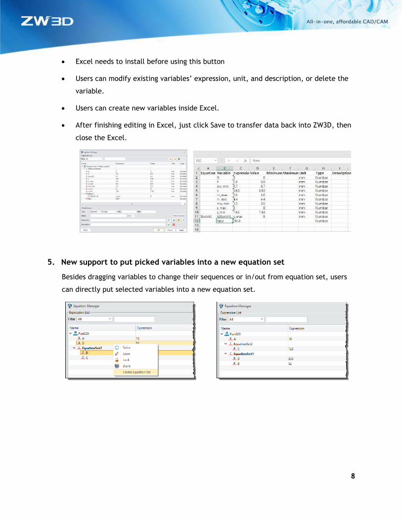
4. New “Edit equations in Excel”
“Edit equations in Excel” button will open the installed Excel program and allow users to
edit the equations with Excel.
8
• Excel needs to install before using this button
• Users can modify existing variables’ expression, unit, and description, or delete the
variable.
• Users can create new variables inside Excel.
• After finishing editing in Excel, just click Save to transfer data back into ZW3D, then
close the Excel.
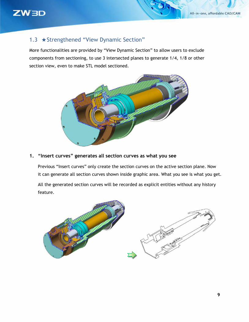
5. New support to put picked variables into a new equation set
Besides dragging variables to change their sequences or in/out from equation set, users
can directly put selected variables into a new equation set.
9
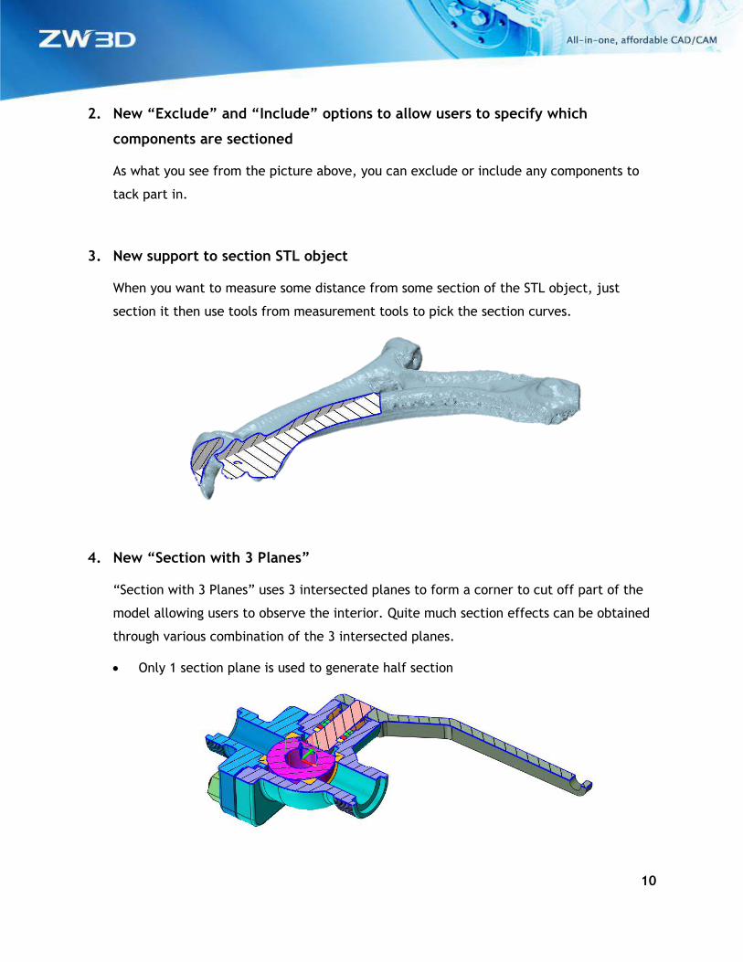
1.3 ★Strengthened “View Dynamic Section”
More functionalities are provided by “View Dynamic Section” to allow users to exclude
components from sectioning, to use 3 intersected planes to generate 1/4, 1/8 or other
section view, even to make STL model sectioned.
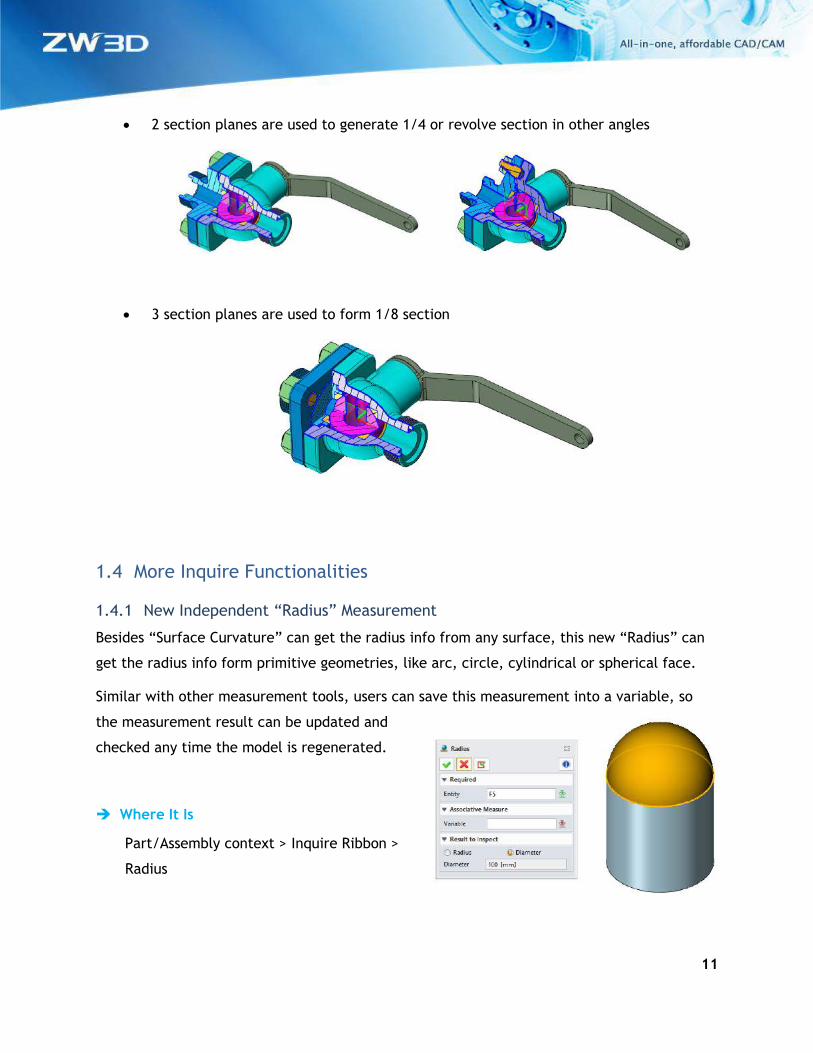
1. “Insert curves” generates all section curves as what you see
Previous “Insert curves” only create the section curves on the active section plane. Now
it can generate all section curves shown inside graphic area. What you see is what you get.
All the generated section curves will be recorded as explicit entities without any history
feature.
10
2. New “Exclude” and “Include” options to allow users to specify which
components are sectioned
As what you see from the picture above, you can exclude or include any components to
tack part in.
3. New support to section STL object
When you want to measure some distance from some section of the STL object, just
section it then use tools from measurement tools to pick the section curves.
4. New “Section with 3 Planes”
“Section with 3 Planes” uses 3 intersected planes to form a corner to cut off part of the
model allowing users to observe the interior. Quite much section effects can be obtained
through various combination of the 3 intersected planes.
• Only 1 section plane is used to generate half section
11
• 2 section planes are used to generate 1/4 or revolve section in other angles
• 3 section planes are used to form 1/8 section
1.4 More Inquire Functionalities
1.4.1 New Independent “Radius” Measurement
Besides “Surface Curvature” can get the radius info from any surface, this new “Radius” can
get the radius info form primitive geometries, like arc, circle, cylindrical or spherical face.
Similar with other measurement tools, users can save this measurement into a variable, so
the measurement result can be updated and
checked any time the model is regenerated.
Where It Is
Part/Assembly context > Inquire Ribbon >
Radius
12
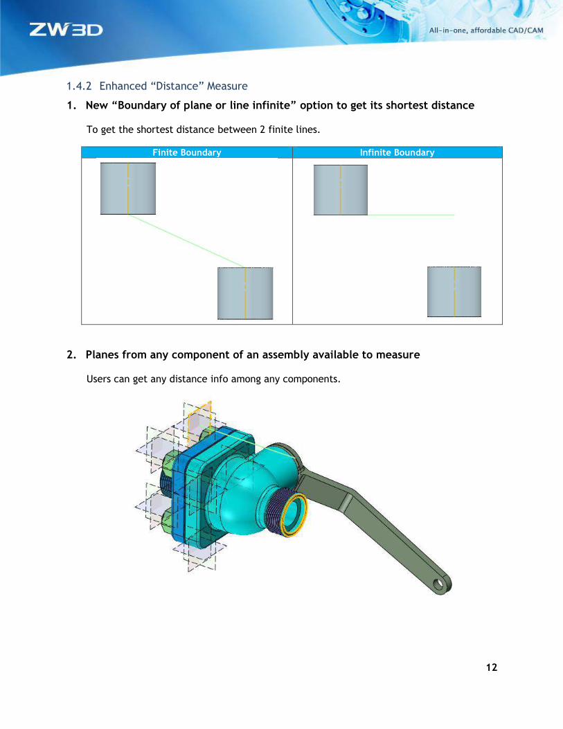
1.4.2 Enhanced “Distance” Measure
1. New “Boundary of plane or line infinite” option to get its shortest distance
To get the shortest distance between 2 finite lines.
Finite Boundary Infinite Boundary
2. Planes from any component of an assembly available to measure
Users can get any distance info among any components.
13
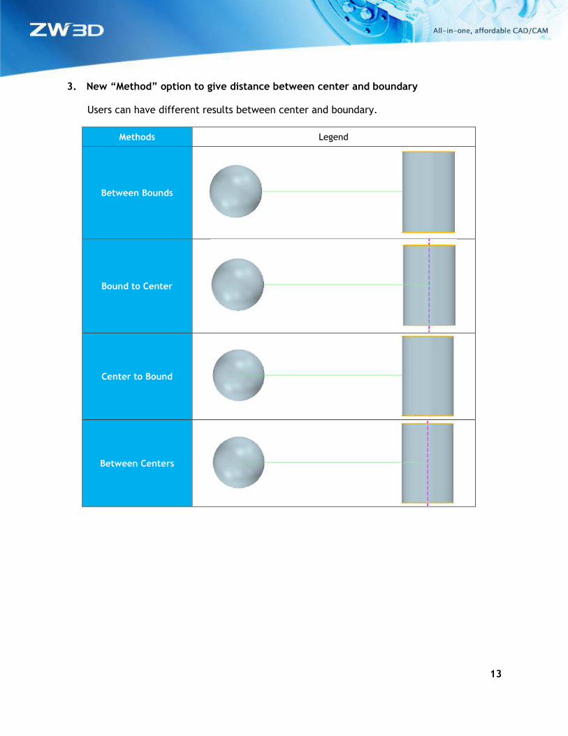
3. New “Method” option to give distance between center and boundary
Users can have different results between center and boundary.
Methods Legend
Between Bounds
Bound to Center
Center to Bound
Between Centers
14
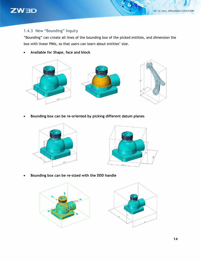
1.4.3 New “Bounding” Inquiry
“Bounding” can create all lines of the bounding box of the picked entities, and dimension the
box with linear PMIs, so that users can learn about entities’ size.
• Available for Shape, face and block
• Bounding box can be re-oriented by picking different datum planes
• Bounding box can be re-sized with the DDD handle
15
Where It Is
Part/Assembly context > PMI Ribbon > Bounding
1.4.4 Other Changes in Inquire
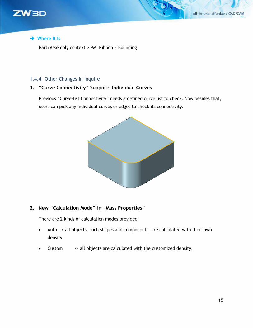
1. “Curve Connectivity” Supports Individual Curves
Previous “Curve-list Connectivity” needs a defined curve list to check. Now besides that,
users can pick any individual curves or edges to check its connectivity.
2. New “Calculation Mode” in “Mass Properties”
There are 2 kinds of calculation modes provided:
• Auto -> all objects, such shapes and components, are calculated with their own
density.
• Custom -> all objects are calculated with the customized density.
16
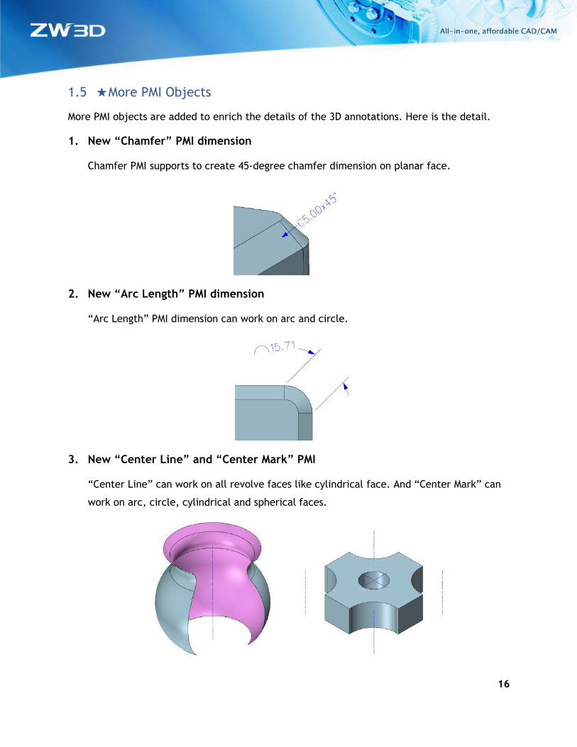
1.5 ★More PMI Objects
More PMI objects are added to enrich the details of the 3D annotations. Here is the detail.
1. New “Chamfer” PMI dimension
Chamfer PMI supports to create 45-degree chamfer dimension on planar face.
2. New “Arc Length” PMI dimension
“Arc Length” PMI dimension can work on arc and circle.
3. New “Center Line” and “Center Mark” PMI
“Center Line” can work on all revolve faces like cylindrical face. And “Center Mark” can
work on arc, circle, cylindrical and spherical faces.
17
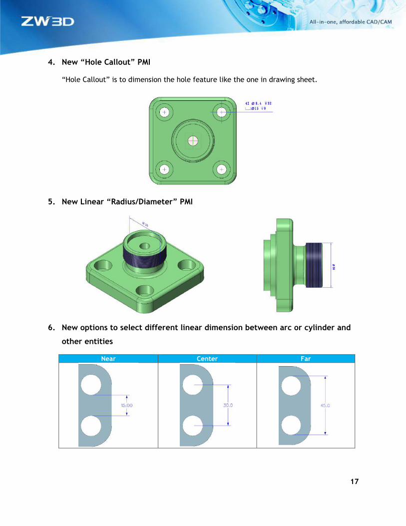
4. New “Hole Callout” PMI
“Hole Callout” is to dimension the hole feature like the one in drawing sheet.
5. New Linear “Radius/Diameter” PMI
6. New options to select different linear dimension between arc or cylinder and
other entities
Near Center Far
18
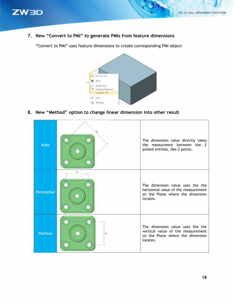
7. New “Convert to PMI” to generate PMIs from feature dimensions
“Convert to PMI” uses feature dimensions to create corresponding PMI object
8. New “Method” option to change linear dimension into other result
Auto
The dimension value directly takes the measurment between the 2 picked entities, like 2 points.
Horizontal
The dimension value uses the the horizontal value of the measurement on the Plane where the dimension locates.
Vertical
The dimension value uses the the vertical value of the measurement on the Plane where the dimension locates.
19
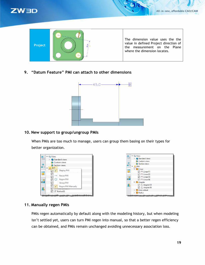
Project
The dimension value uses the the value in defined Project direction of the measurement on the Plane where the dimension locates.
9. “Datum Feature” PMI can attach to other dimensions
10. New support to group/ungroup PMIs
When PMIs are too much to manage, users can group them basing on their types for
better organization.
11. Manually regen PMIs
PMIs regen automatically by default along with the modeling history, but when modeling
isn’t settled yet, users can turn PMI regen into manual, so that a better regen efficiency
can be obtained, and PMIs remain unchanged avoiding unnecessary association loss.
20
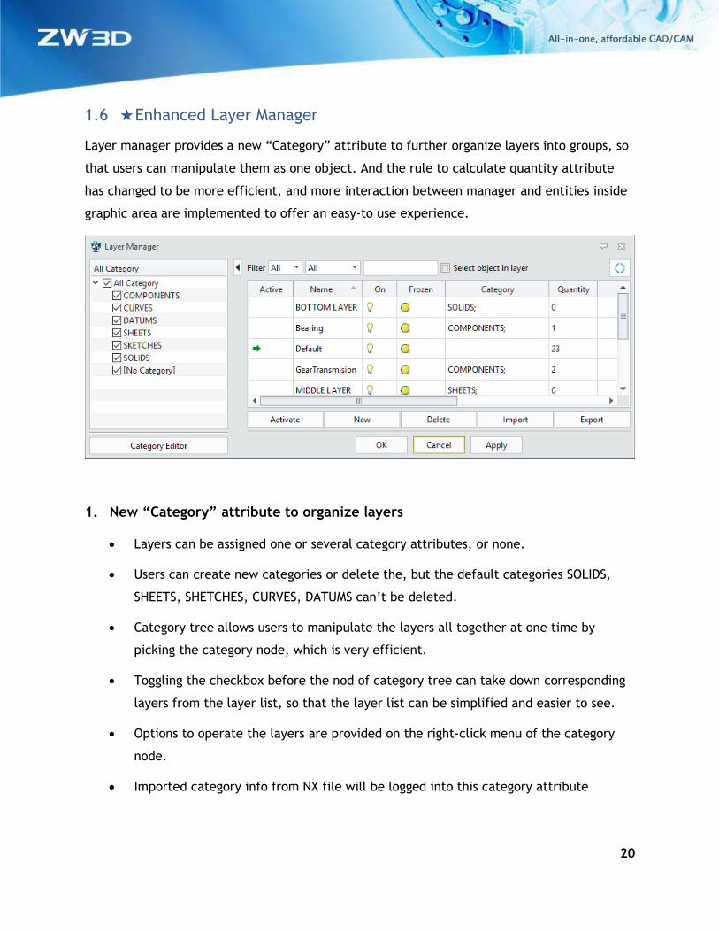
1.6 ★Enhanced Layer Manager
Layer manager provides a new “Category” attribute to further organize layers into groups, so
that users can manipulate them as one object. And the rule to calculate quantity attribute
has changed to be more efficient, and more interaction between manager and entities inside
graphic area are implemented to offer an easy-to use experience.
1. New “Category” attribute to organize layers
• Layers can be assigned one or several category attributes, or none.
• Users can create new categories or delete the, but the default categories SOLIDS,
SHEETS, SHETCHES, CURVES, DATUMS can’t be deleted.
• Category tree allows users to manipulate the layers all together at one time by
picking the category node, which is very efficient.
• Toggling the checkbox before the nod of category tree can take down corresponding
layers from the layer list, so that the layer list can be simplified and easier to see.
• Options to operate the layers are provided on the right-click menu of the category
node.
• Imported category info from NX file will be logged into this category attribute
21
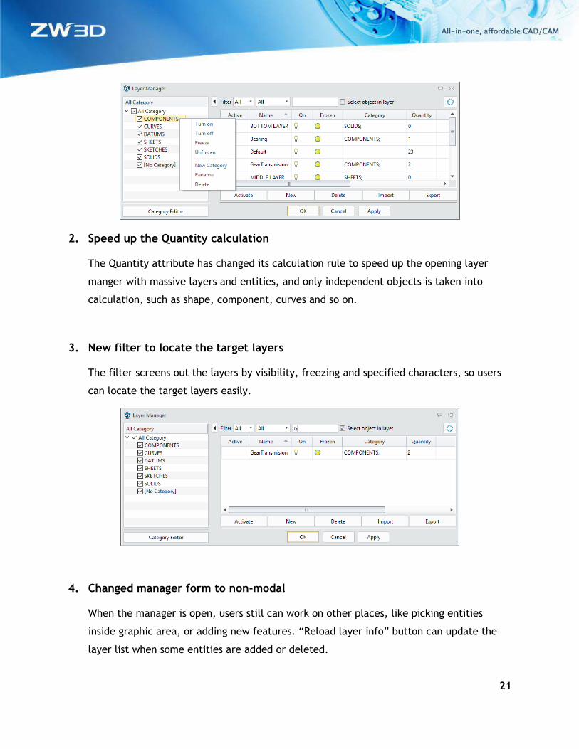
2. Speed up the Quantity calculation
The Quantity attribute has changed its calculation rule to speed up the opening layer
manger with massive layers and entities, and only independent objects is taken into
calculation, such as shape, component, curves and so on.
3. New filter to locate the target layers
The filter screens out the layers by visibility, freezing and specified characters, so users
can locate the target layers easily.
4. Changed manager form to non-modal
When the manager is open, users still can work on other places, like picking entities
inside graphic area, or adding new features. “Reload layer info” button can update the
layer list when some entities are added or deleted.
22
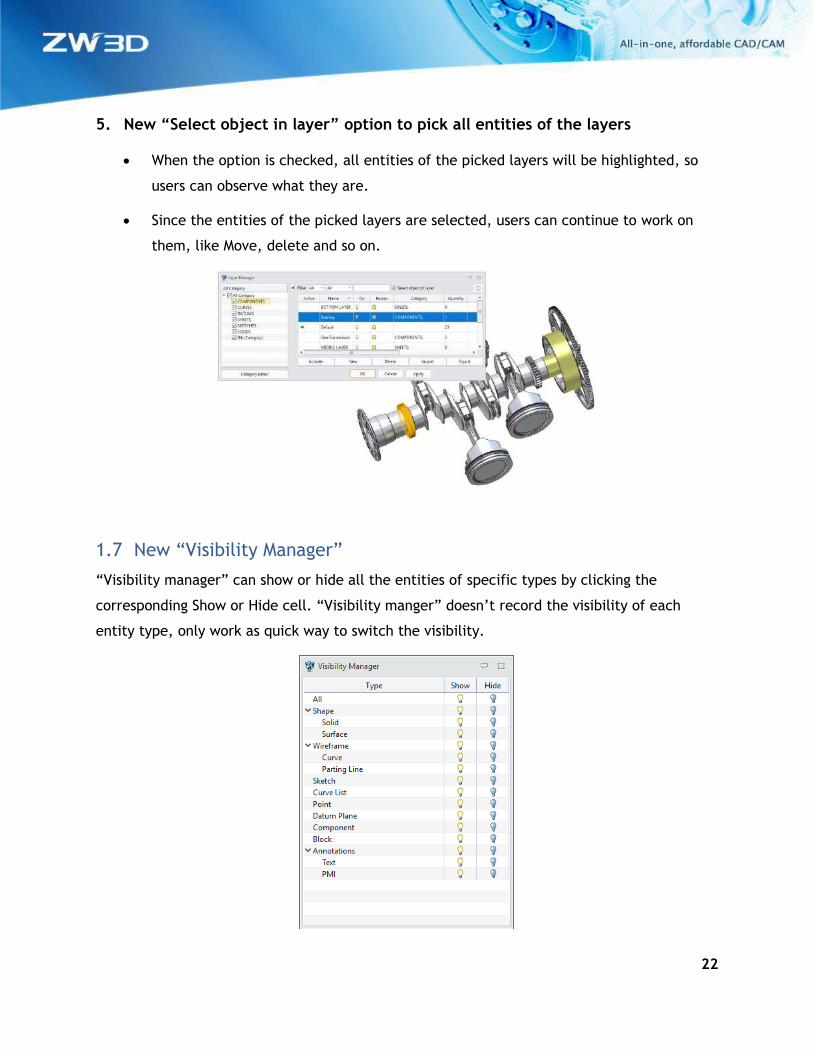
5. New “Select object in layer” option to pick all entities of the layers
• When the option is checked, all entities of the picked layers will be highlighted, so
users can observe what they are.
• Since the entities of the picked layers are selected, users can continue to work on
them, like Move, delete and so on.
1.7 New “Visibility Manager”
“Visibility manager” can show or hide all the entities of specific types by clicking the
corresponding Show or Hide cell. “Visibility manger” doesn’t record the visibility of each
entity type, only work as quick way to switch the visibility.
23
What it is
Part/Assembly context > AD toolbar > Visibility group > Visibility Manager
Drafting context > AD toolbar > Visibility group > Visibility Manager
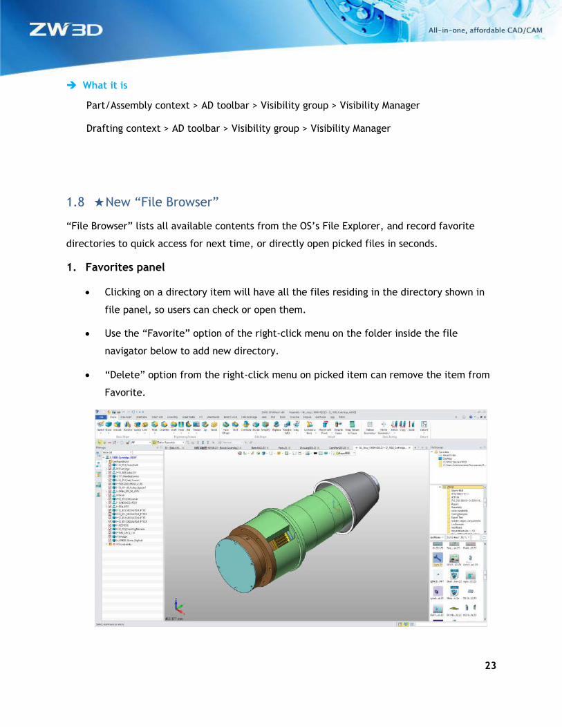
1.8 ★New “File Browser”
“File Browser” lists all available contents from the OS’s File Explorer, and record favorite
directories to quick access for next time, or directly open picked files in seconds.
1. Favorites panel
• Clicking on a directory item will have all the files residing in the directory shown in
file panel, so users can check or open them.
• Use the “Favorite” option of the right-click menu on the folder inside the file
navigator below to add new directory.
• “Delete” option from the right-click menu on picked item can remove the item from
Favorite.
24
2. Folder navigator panel
Available folders are listed here to navigate.
3. File panel
This panel lists all files supported by ZW3D.
• 2 kinds of layout: List mode and Tale mode.
• File type filter is provided.
• File name search
• 2 ways to open a file: double-clicking and drag-drop
What it is
All contexts > Prompt line > File Browser
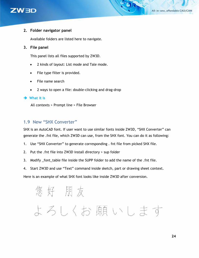
1.9 New “SHX Converter”
SHX is an AutoCAD font. If user want to use similar fonts inside ZW3D, “SHX Converter” can
generate the .fnt file, which ZW3D can use, from the SHX font. You can do it as following:
1. Use “SHX Converter” to generate corresponding . fnt file from picked SHX file.
2. Put the .fnt file into ZW3D install directory > sup folder
3. Modify _font_table file inside the SUPP folder to add the name of the .fnt file.
4. Start ZW3D and use “Text” command inside sketch, part or drawing sheet context.
Here is an example of what SHX font looks like inside ZW3D after conversion.
25
What it is
Part/Assembly context > Tools Ribbon > SHX Converter
Sketch context > Tools Ribbon > SHX Converter
Drafting context > Tools Ribbon > SHX Converter
1.10 Tweaked License Manager
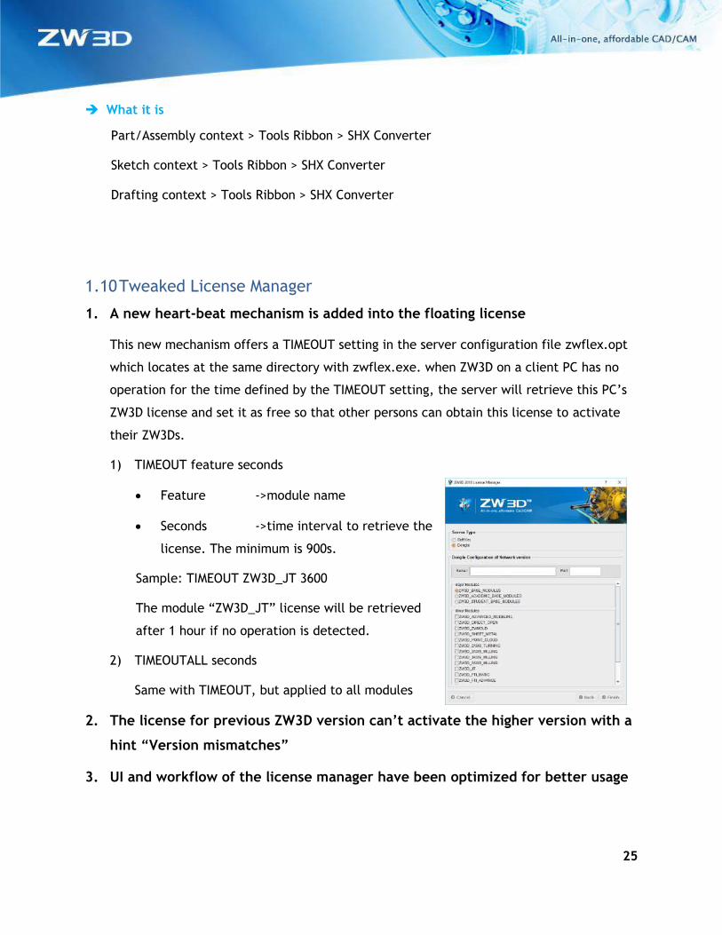
1. A new heart-beat mechanism is added into the floating license
This new mechanism offers a TIMEOUT setting in the server configuration file zwflex.opt
which locates at the same directory with zwflex.exe. when ZW3D on a client PC has no
operation for the time defined by the TIMEOUT setting, the server will retrieve this PC’s
ZW3D license and set it as free so that other persons can obtain this license to activate
their ZW3Ds.
1) TIMEOUT feature seconds
• Feature ->module name
• Seconds ->time interval to retrieve the
license. The minimum is 900s.
Sample: TIMEOUT ZW3D_JT 3600
The module “ZW3D_JT” license will be retrieved
after 1 hour if no operation is detected.
2) TIMEOUTALL seconds
Same with TIMEOUT, but applied to all modules
2. The license for previous ZW3D version can’t activate the higher version with a
hint “Version mismatches”
3. UI and workflow of the license manager have been optimized for better usage
26
2 Translator
2.1 Import
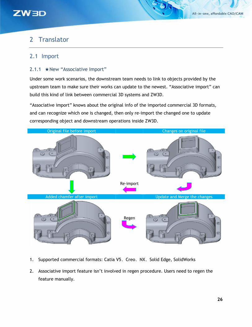
2.1.1 ★New “Associative Import”
Under some work scenarios, the downstream team needs to link to objects provided by the
upstream team to make sure their works can update to the newest. “Associative import” can
build this kind of link between commercial 3D systems and ZW3D.
“Associative import” knows about the original info of the imported commercial 3D formats,
and can recognize which one is changed, then only re-import the changed one to update
corresponding object and downstream operations inside ZW3D.
Original file before import Changes on original file
Re-import
Added chamfer after import Update and Merge the changes
Regen
1. Supported commercial formats: Catia V5、Creo、NX、Solid Edge, SolidWorks
2. Associative import feature isn’t involved in regen procedure. Users need to regen the
feature manually.
27
3. Only modified file will be re-imported during associative import feature update.
4. When the original commercial file has changed, features operating on entities of the
associative import model will keep regenerating successfully if those entities don’t
change much.
5. Components from associative imported assembly can’t be edited.
6. Associative import feature can be broken, and after that, components from the
associative imported assembly will convert into regular ones, so that users can
manipulate them as they like.
7. When deleting the associative import feature, all entities and components from that
feature will be deleted.
What it is
Part/Assembly context > File Menu > Import > Import Setting form > Associative import
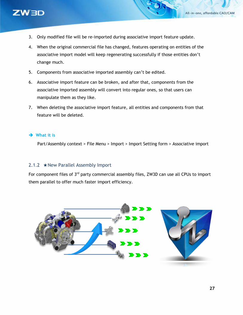
2.1.2 ★New Parallel Assembly Import
For component files of 3rd party commercial assembly files, ZW3D can use all CPUs to import
them parallel to offer much faster import efficiency.
28
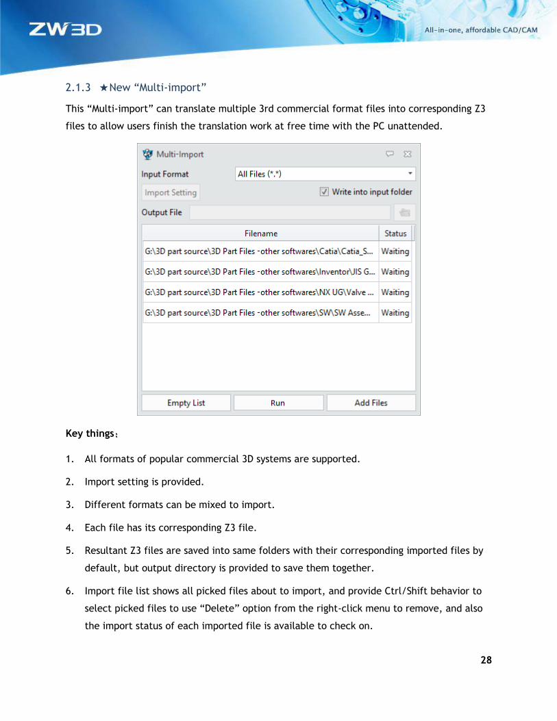
2.1.3 ★New “Multi-import”
This “Multi-import” can translate multiple 3rd commercial format files into corresponding Z3
files to allow users finish the translation work at free time with the PC unattended.
Key things:
1. All formats of popular commercial 3D systems are supported.
2. Import setting is provided.
3. Different formats can be mixed to import.
4. Each file has its corresponding Z3 file.
5. Resultant Z3 files are saved into same folders with their corresponding imported files by
default, but output directory is provided to save them together.
6. Import file list shows all picked files about to import, and provide Ctrl/Shift behavior to
select picked files to use “Delete” option from the right-click menu to remove, and also
the import status of each imported file is available to check on.
29
Where it is
Part/Assembly context > File menu > Multi-import
Part/Assembly context > Data exchange Ribbon > Multi-import
2.1.4 Enhancements for Import
1. Search support for importing 3rd party commercial assembly files
If the component files of a 3rd party commercial assembly file don’t locate at the same
directory, ZW3D will search the folder added on the import setting form.
2. New “Auto save files as full shatter” option to save imported components as
individual files
This new option only work on 3rd party commercial assembly files, and all the imported
individual files are saved into directory where original files are.
3. New support to read “Category” info from NX file
This imported category info will save into the “Category” attribute of the layers.
4. New OBJ import support
Point cloud ribbon > OBJ import can import object with color and texture.
30
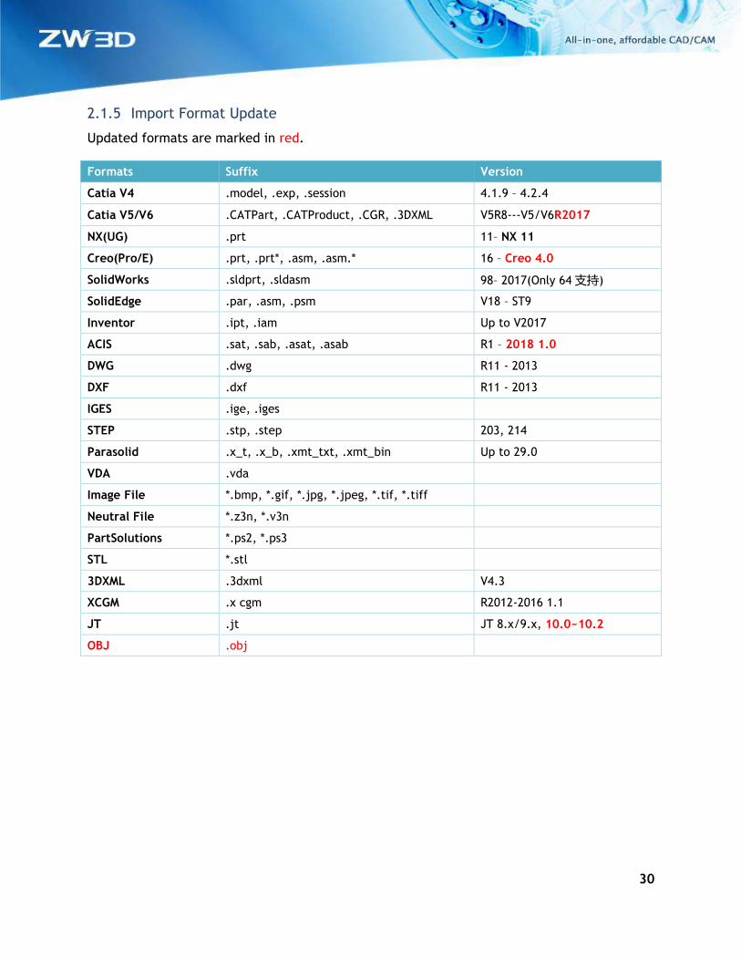
2.1.5 Import Format Update
Updated formats are marked in red.
Formats Suffix Version
Catia V4 .model, .exp, .session 4.1.9 – 4.2.4
Catia V5/V6 .CATPart, .CATProduct, .CGR, .3DXML V5R8---V5/V6R2017
NX(UG) .prt 11– NX 11
Creo(Pro/E) .prt, .prt*, .asm, .asm.* 16 – Creo 4.0
SolidWorks .sldprt, .sldasm 98– 2017(Only 64支持)
SolidEdge .par, .asm, .psm V18 – ST9
Inventor .ipt, .iam Up to V2017
ACIS .sat, .sab, .asat, .asab R1 – 2018 1.0
DWG .dwg R11 - 2013
DXF .dxf R11 - 2013
IGES .ige, .iges
STEP .stp, .step 203, 214
Parasolid .x_t, .x_b, .xmt_txt, .xmt_bin Up to 29.0
VDA .vda
Image File *.bmp, *.gif, *.jpg, *.jpeg, *.tif, *.tiff
Neutral File *.z3n, *.v3n
PartSolutions *.ps2, *.ps3
STL *.stl
3DXML .3dxml V4.3
XCGM .x cgm R2012-2016 1.1
JT .jt JT 8.x/9.x, 10.0~10.2
OBJ .obj
31
2.2 Export
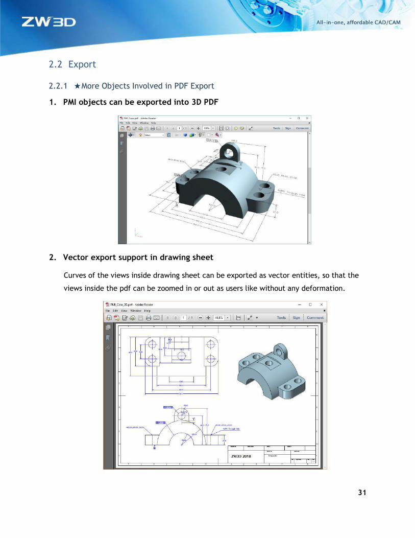
2.2.1 ★More Objects Involved in PDF Export
1. PMI objects can be exported into 3D PDF
2. Vector export support in drawing sheet
Curves of the views inside drawing sheet can be exported as vector entities, so that the
views inside the pdf can be zoomed in or out as users like without any deformation.
32
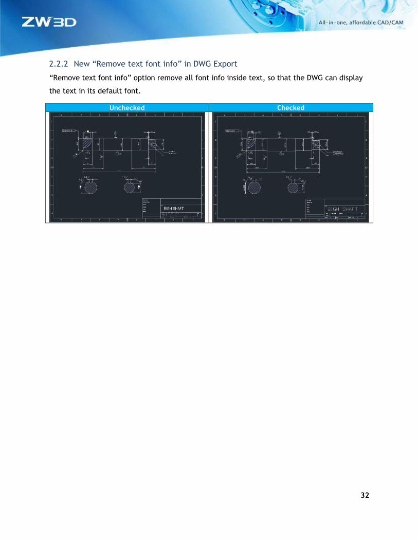
2.2.2 New “Remove text font info” in DWG Export
“Remove text font info” option remove all font info inside text, so that the DWG can display
the text in its default font.
Unchecked Checked
33
3 CAD
3.1 Sketch Design
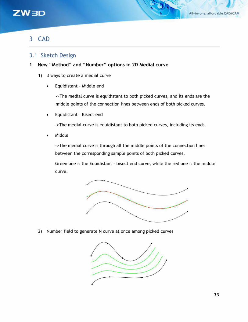
1. New “Method” and “Number” options in 2D Medial curve
1) 3 ways to create a medial curve
• Equidistant – Middle end
->The medial curve is equidistant to both picked curves, and its ends are the
middle points of the connection lines between ends of both picked curves.
• Equidistant – Bisect end
->The medial curve is equidistant to both picked curves, including its ends.
• Middle
->The medial curve is through all the middle points of the connection lines
between the corresponding sample points of both picked curves.
Green one is the Equidistant – bisect end curve, while the red one is the middle
curve.
2) Number field to generate N curve at once among picked curves
34
2. New “Pattern along curve” in Pattern
No pattern constraint will be added onto instances of the “Pattern along curve”.
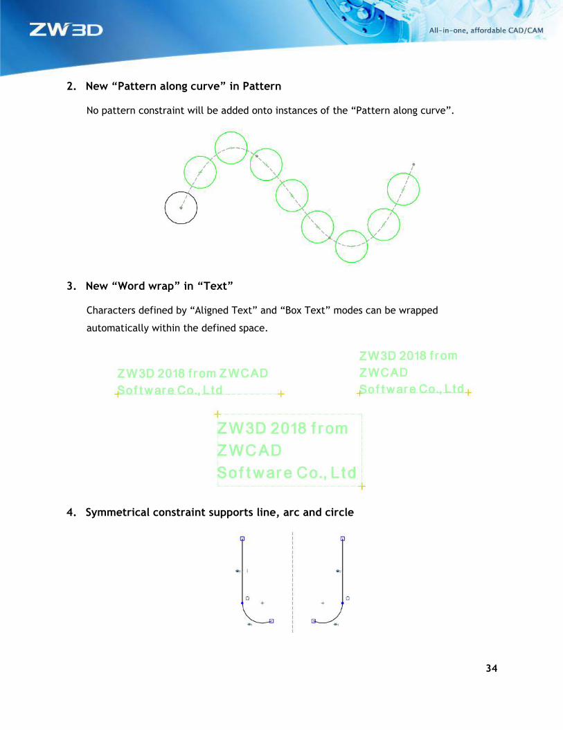
3. New “Word wrap” in “Text”
Characters defined by “Aligned Text” and “Box Text” modes can be wrapped
automatically within the defined space.
4. Symmetrical constraint supports line, arc and circle
35
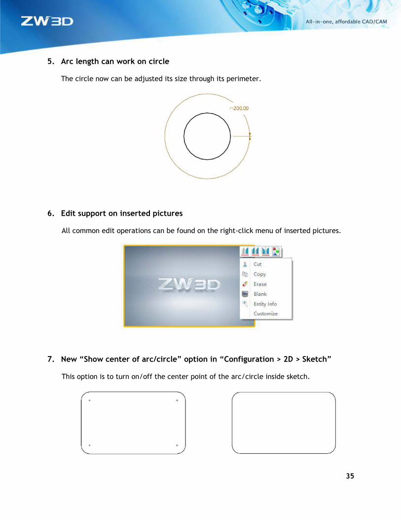
5. Arc length can work on circle
The circle now can be adjusted its size through its perimeter.
6. Edit support on inserted pictures
All common edit operations can be found on the right-click menu of inserted pictures.
7. New “Show center of arc/circle” option in “Configuration > 2D > Sketch”
This option is to turn on/off the center point of the arc/circle inside sketch.
36
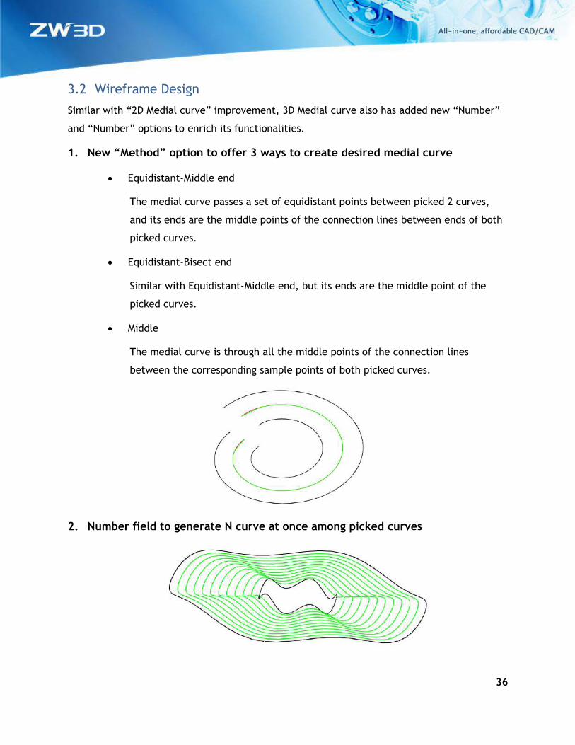
3.2 Wireframe Design
Similar with “2D Medial curve” improvement, 3D Medial curve also has added new “Number”
and “Number” options to enrich its functionalities.
1. New “Method” option to offer 3 ways to create desired medial curve
• Equidistant-Middle end
The medial curve passes a set of equidistant points between picked 2 curves,
and its ends are the middle points of the connection lines between ends of both
picked curves.
• Equidistant-Bisect end
Similar with Equidistant-Middle end, but its ends are the middle point of the
picked curves.
• Middle
The medial curve is through all the middle points of the connection lines
between the corresponding sample points of both picked curves.
2. Number field to generate N curve at once among picked curves
37
3.3 Part Design
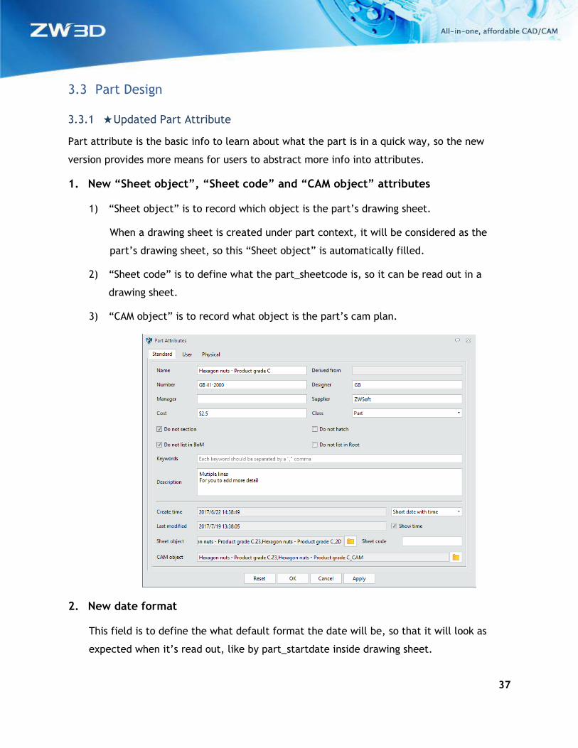
3.3.1 ★Updated Part Attribute
Part attribute is the basic info to learn about what the part is in a quick way, so the new
version provides more means for users to abstract more info into attributes.
1. New “Sheet object”, “Sheet code” and “CAM object” attributes
1) “Sheet object” is to record which object is the part’s drawing sheet.
When a drawing sheet is created under part context, it will be considered as the
part’s drawing sheet, so this “Sheet object” is automatically filled.
2) “Sheet code” is to define what the part_sheetcode is, so it can be read out in a
drawing sheet.
3) “CAM object” is to record what object is the part’s cam plan.
2. New date format
This field is to define the what default format the date will be, so that it will look as
expected when it’s read out, like by part_startdate inside drawing sheet.
38
Short date ->2017/8/28
Long date ->Monday, August 28, 2017
yyyy-M-d H:mm:ss ->2017-08-28 10:39:00
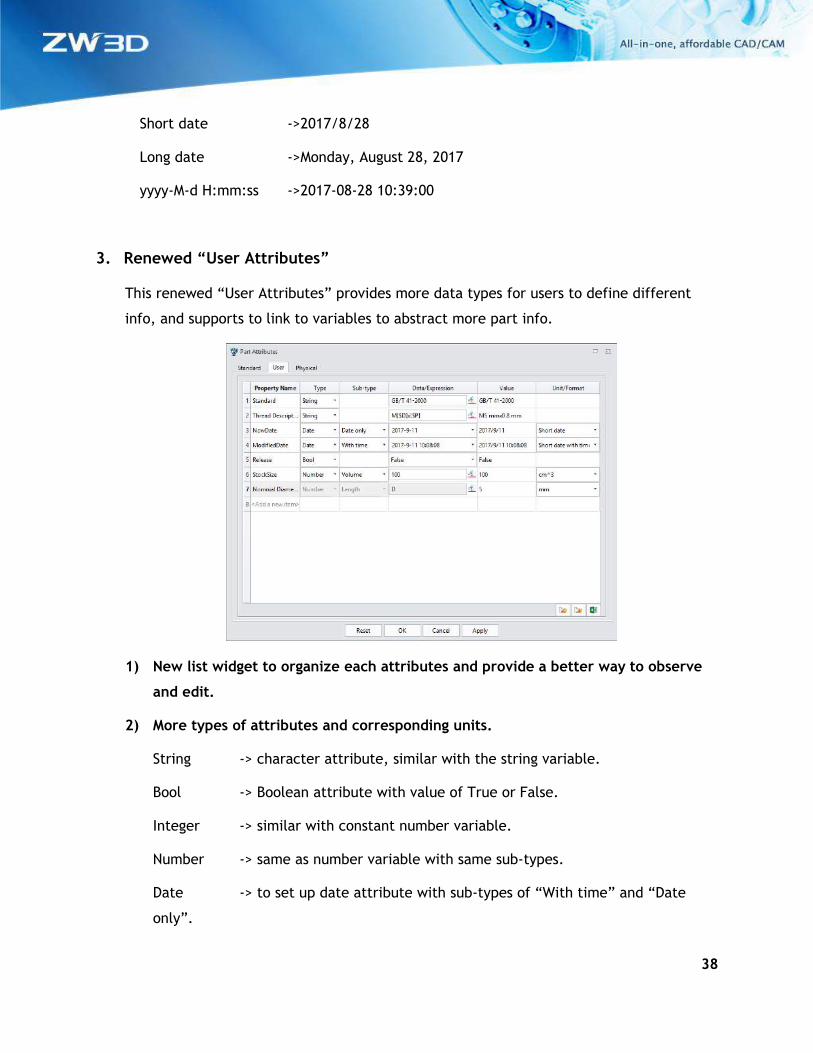
3. Renewed “User Attributes”
This renewed “User Attributes” provides more data types for users to define different
info, and supports to link to variables to abstract more part info.
1) New list widget to organize each attributes and provide a better way to observe
and edit.
2) More types of attributes and corresponding units.
String -> character attribute, similar with the string variable.
Bool -> Boolean attribute with value of True or False.
Integer -> similar with constant number variable.
Number -> same as number variable with same sub-types.
Date -> to set up date attribute with sub-types of “With time” and “Date
only”.
39
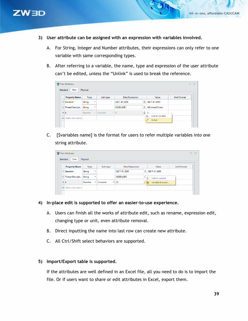
3) User attribute can be assigned with an expression with variables involved.
A. For String, Integer and Number attributes, their expressions can only refer to one
variable with same corresponding types.
B. After referring to a variable, the name, type and expression of the user attribute
can’t be edited, unless the “Unlink” is used to break the reference.
C. [$variables name] is the format for users to refer multiple variables into one
string attribute.
4) In-place edit is supported to offer an easier-to-use experience.
A. Users can finish all the works of attribute edit, such as rename, expression edit,
changing type or unit, even attribute removal.
B. Direct inputting the name into last row can create new attribute.
C. All Ctrl/Shift select behaviors are supported.
5) Import/Export table is supported.
If the attributes are well defined in an Excel file, all you need to do is to import the
file. Or if users want to share or edit attributes in Excel, export them.
40
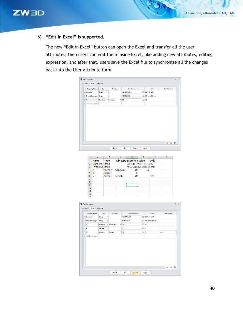
6) “Edit in Excel” is supported.
The new “Edit in Excel” button can open the Excel and transfer all the user
attributes, then users can edit them inside Excel, like adding new attributes, editing
expression, and after that, users save the Excel file to synchronize all the changes
back into the User attribute form.

41
3.3.2 ★Expanded “Config Table”
“Config Table” has been further developed into a compound tool to include all common
contents that are used in making part family, such as part attributes, variables, modeling
features, assembly component and their constraints, so that users can easily set up all items
of a part family at one form.
1. New configurable item list for part modeling
On previous version, users can pick items from the history modeling tree or from the
graphic area. Besides this, new version provides a list of all configurable items of part
modeling for users to choose.
1) Added standard part attributes to configure
A. “Color” is one of the new added standard attributes to reset the part color when
activate each part config or generate part instance.
After “Color” is configured, activating each configuration will erase existing color
and texture and reset to the specified color.
B. “Instance Name” is the other of the new added standard attributes to define the
object name of generated instance. Users can define how the name would be
through the “Instance name option” form from the right-click menu.
42
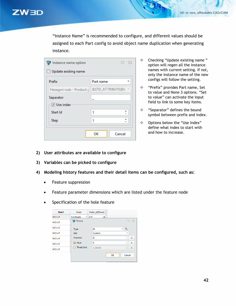
“Instance Name” is recommended to configure, and different values should be
assigned to each Part config to avoid object name duplication when generating
instance.
Checking “Update existing name ”
option will regen all the instance
names with current setting. If not,
only the instance name of the new
configs will follow the setting.
“Prefix” provides Part name, Set
to value and None 3 options. “Set
to value” can activate the input
field to link to some key items.
“Separator” defines the bound
symbol between prefix and index.
Options below the “Use Index”
define what index to start with
and how to increase.
2) User attributes are available to configure
3) Variables can be picked to configure
4) Modeling history features and their detail items can be configured, such as:
• Feature suppression
• Feature parameter dimensions which are listed under the feature node
• Specification of the hole feature
43
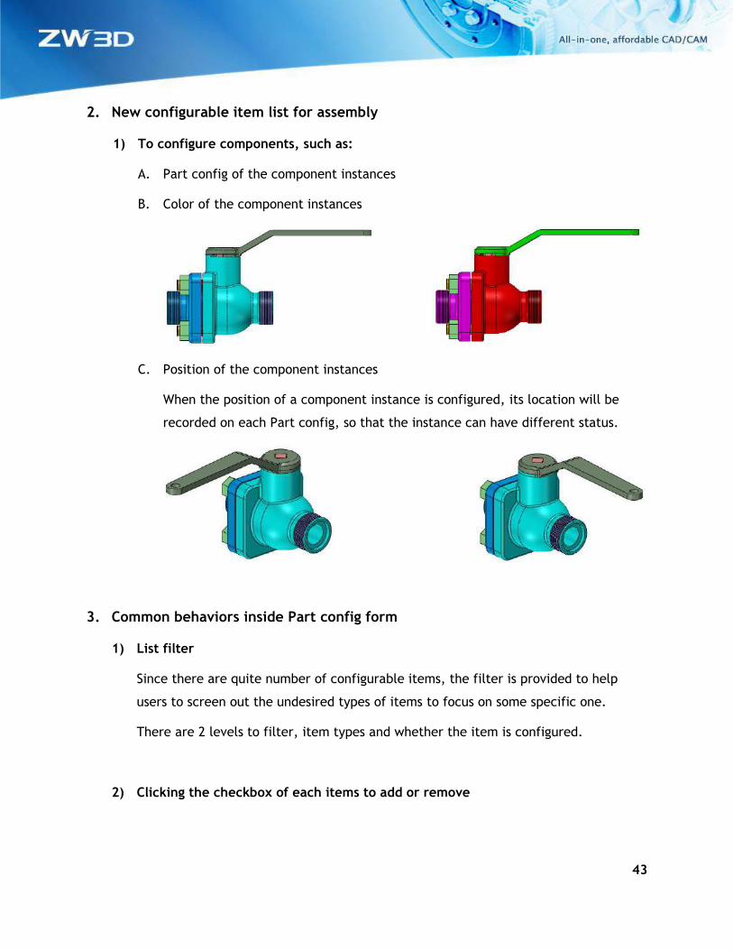
2. New configurable item list for assembly
1) To configure components, such as:
A. Part config of the component instances
B. Color of the component instances
C. Position of the component instances
When the position of a component instance is configured, its location will be
recorded on each Part config, so that the instance can have different status.
3. Common behaviors inside Part config form
1) List filter
Since there are quite number of configurable items, the filter is provided to help
users to screen out the undesired types of items to focus on some specific one.
There are 2 levels to filter, item types and whether the item is configured.
2) Clicking the checkbox of each items to add or remove
44
To define which item needs to configure, simply click the checkbox of each items.
Uncheck the box will remove it from the Part config.
Ctrl/Shift selection is supported.
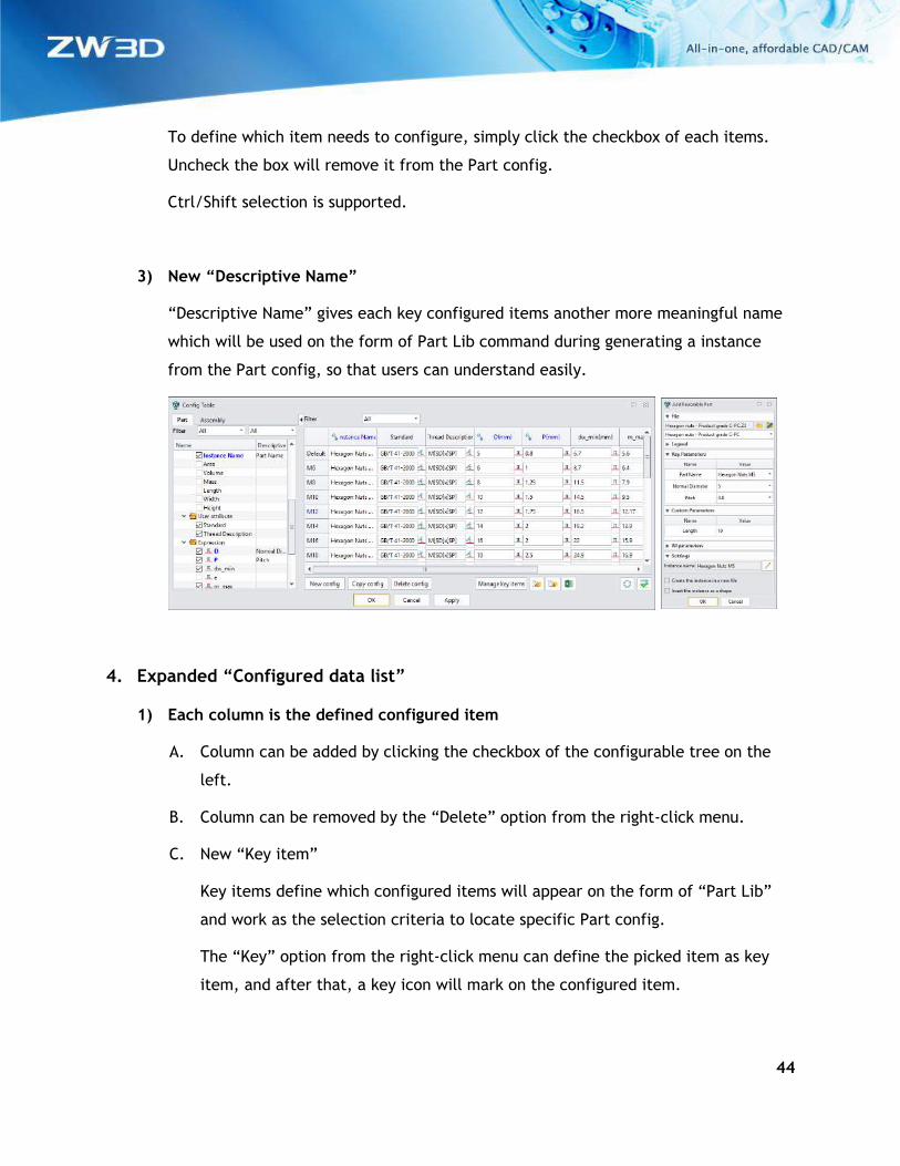
3) New “Descriptive Name”
“Descriptive Name” gives each key configured items another more meaningful name
which will be used on the form of Part Lib command during generating a instance
from the Part config, so that users can understand easily.
4. Expanded “Configured data list”
1) Each column is the defined configured item
A. Column can be added by clicking the checkbox of the configurable tree on the
left.
B. Column can be removed by the “Delete” option from the right-click menu.
C. New “Key item”
Key items define which configured items will appear on the form of “Part Lib”
and work as the selection criteria to locate specific Part config.
The “Key” option from the right-click menu can define the picked item as key
item, and after that, a key icon will mark on the configured item.
45
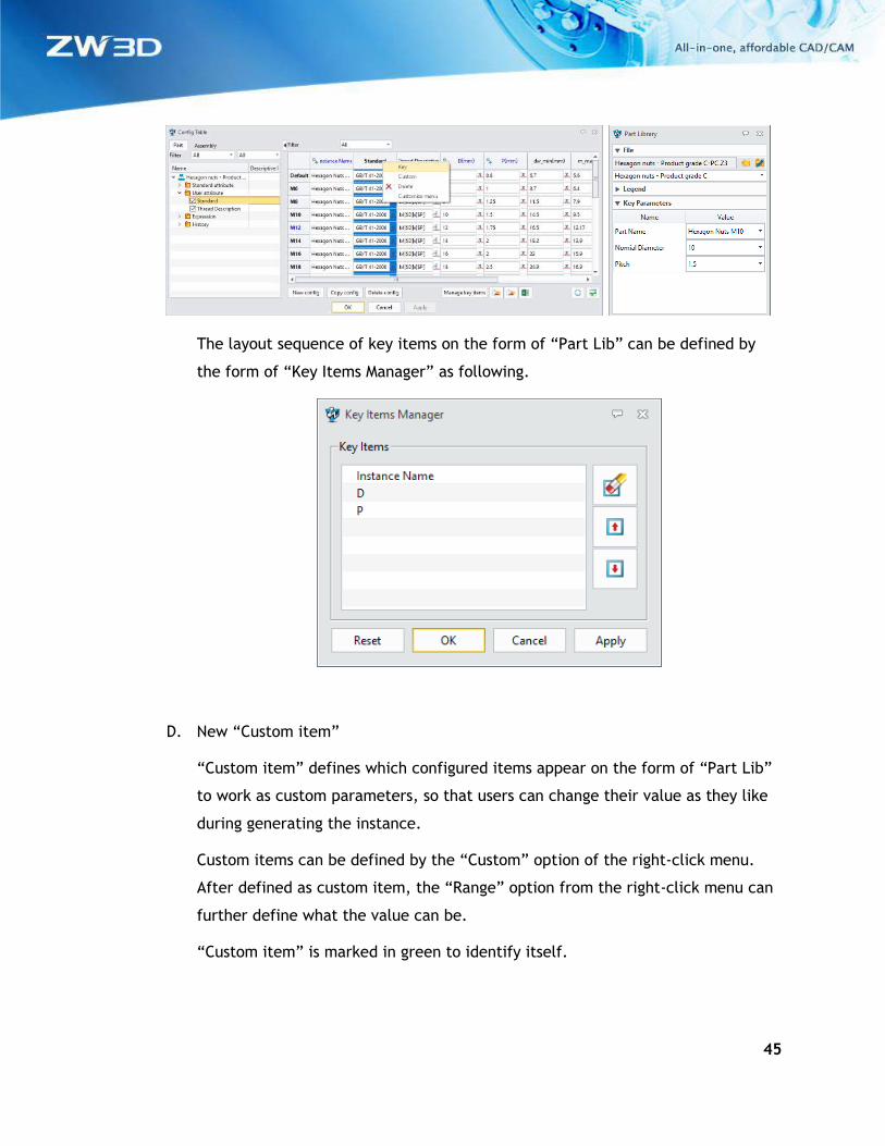
The layout sequence of key items on the form of “Part Lib” can be defined by
the form of “Key Items Manager” as following.
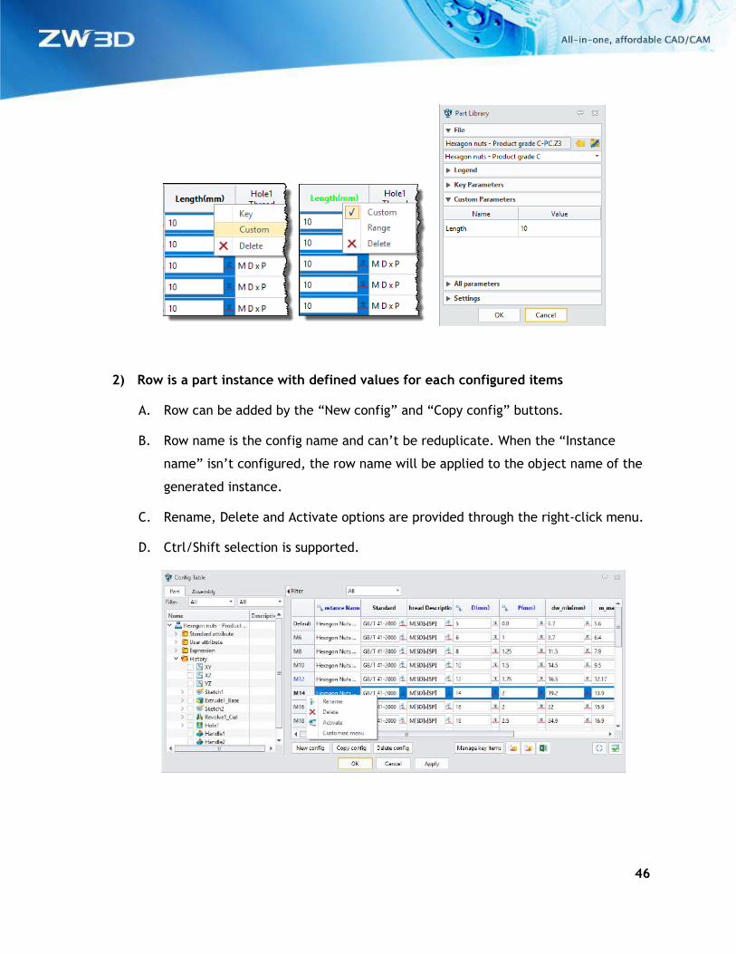
D. New “Custom item”
“Custom item” defines which configured items appear on the form of “Part Lib”
to work as custom parameters, so that users can change their value as they like
during generating the instance.
Custom items can be defined by the “Custom” option of the right-click menu.
After defined as custom item, the “Range” option from the right-click menu can
further define what the value can be.
“Custom item” is marked in green to identify itself.
46
2) Row is a part instance with defined values for each configured items
A. Row can be added by the “New config” and “Copy config” buttons.
B. Row name is the config name and can’t be reduplicate. When the “Instance
name” isn’t configured, the row name will be applied to the object name of the
generated instance.
C. Rename, Delete and Activate options are provided through the right-click menu.
D. Ctrl/Shift selection is supported.
47
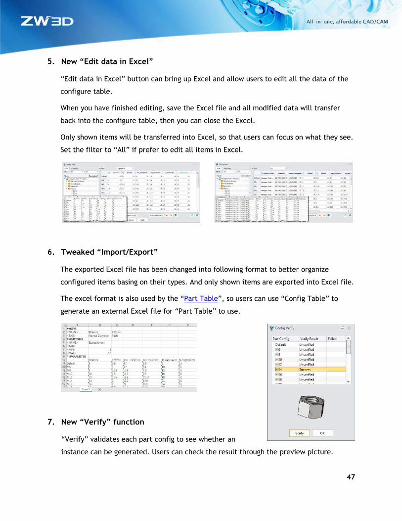
5. New “Edit data in Excel”
“Edit data in Excel” button can bring up Excel and allow users to edit all the data of the
configure table.
When you have finished editing, save the Excel file and all modified data will transfer
back into the configure table, then you can close the Excel.
Only shown items will be transferred into Excel, so that users can focus on what they see.
Set the filter to “All” if prefer to edit all items in Excel.
6. Tweaked “Import/Export”
The exported Excel file has been changed into following format to better organize
configured items basing on their types. And only shown items are exported into Excel file.
The excel format is also used by the “Part Table”, so users can use “Config Table” to
generate an external Excel file for “Part Table” to use.
7. New “Verify” function
“Verify” validates each part config to see whether an
instance can be generated. Users can check the result through the preview picture.
48
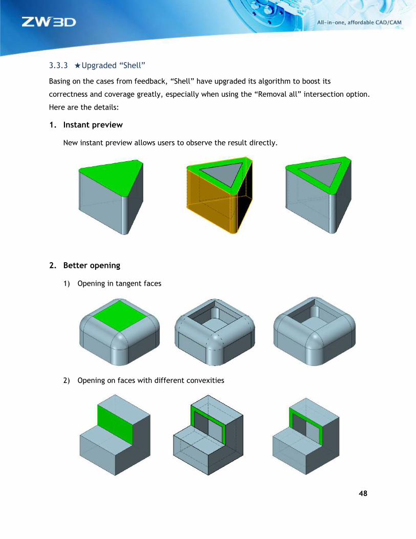
3.3.3 ★Upgraded “Shell”
Basing on the cases from feedback, “Shell” have upgraded its algorithm to boost its
correctness and coverage greatly, especially when using the “Removal all” intersection option.
Here are the details:
1. Instant preview
New instant preview allows users to observe the result directly.
2. Better opening
1) Opening in tangent faces
2) Opening on faces with different convexities
49
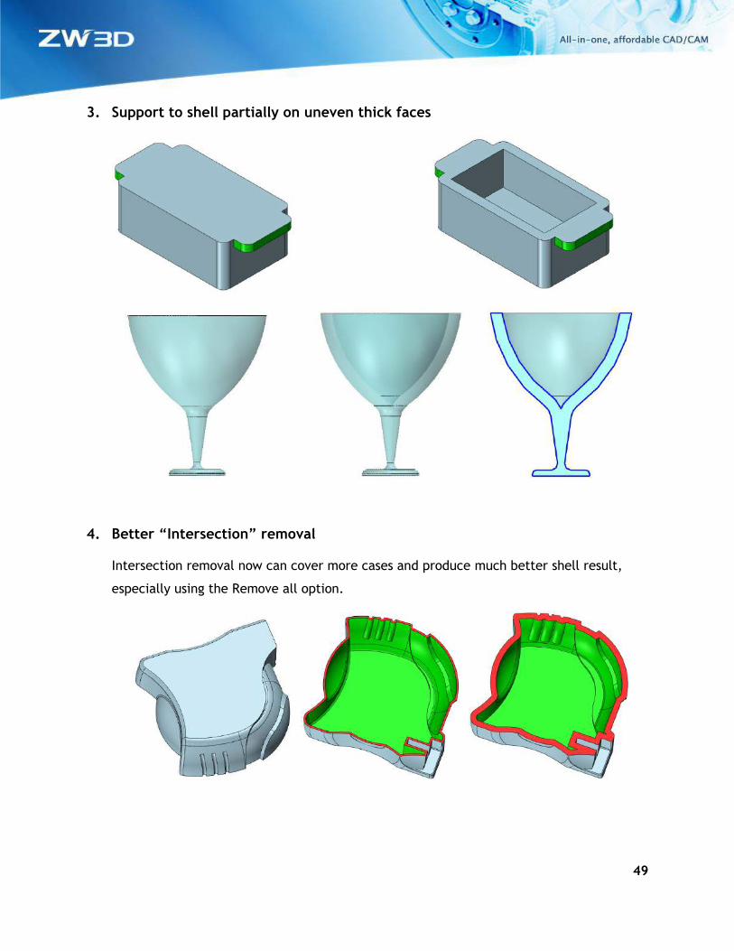
3. Support to shell partially on uneven thick faces
4. Better “Intersection” removal
Intersection removal now can cover more cases and produce much better shell result,
especially using the Remove all option.
50
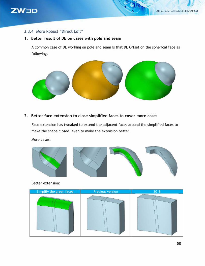
3.3.4 More Robust “Direct Edit”
1. Better result of DE on cases with pole and seam
A common case of DE working on pole and seam is that DE Offset on the spherical face as
following.
2. Better face extension to close simplified faces to cover more cases
Face extension has tweaked to extend the adjacent faces around the simplified faces to
make the shape closed, even to make the extension better.
More cases:
Better extension:
Simplify the green faces Previous version 2018
51
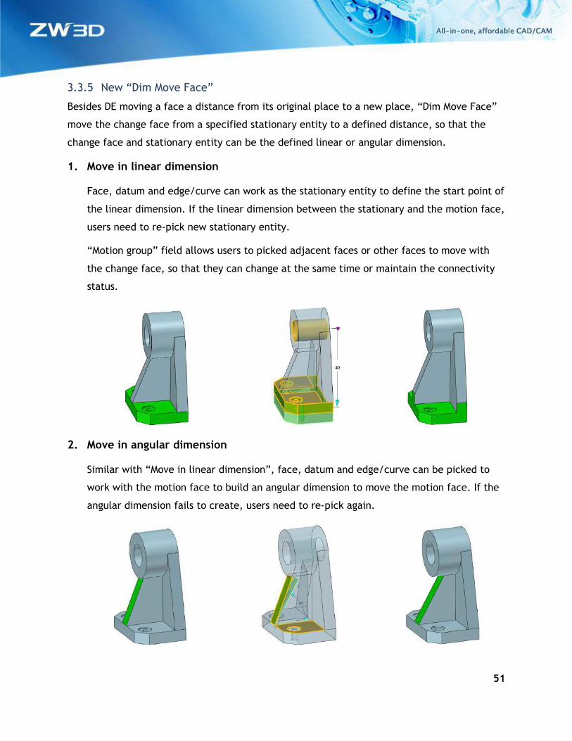
3.3.5 New “Dim Move Face”
Besides DE moving a face a distance from its original place to a new place, “Dim Move Face”
move the change face from a specified stationary entity to a defined distance, so that the
change face and stationary entity can be the defined linear or angular dimension.
1. Move in linear dimension
Face, datum and edge/curve can work as the stationary entity to define the start point of
the linear dimension. If the linear dimension between the stationary and the motion face,
users need to re-pick new stationary entity.
“Motion group” field allows users to picked adjacent faces or other faces to move with
the change face, so that they can change at the same time or maintain the connectivity
status.
2. Move in angular dimension
Similar with “Move in linear dimension”, face, datum and edge/curve can be picked to
work with the motion face to build an angular dimension to move the motion face. If the
angular dimension fails to create, users need to re-pick again.
52
Where it is
Part/Assembly context > Direct Edit Ribbon > Dim Move Face
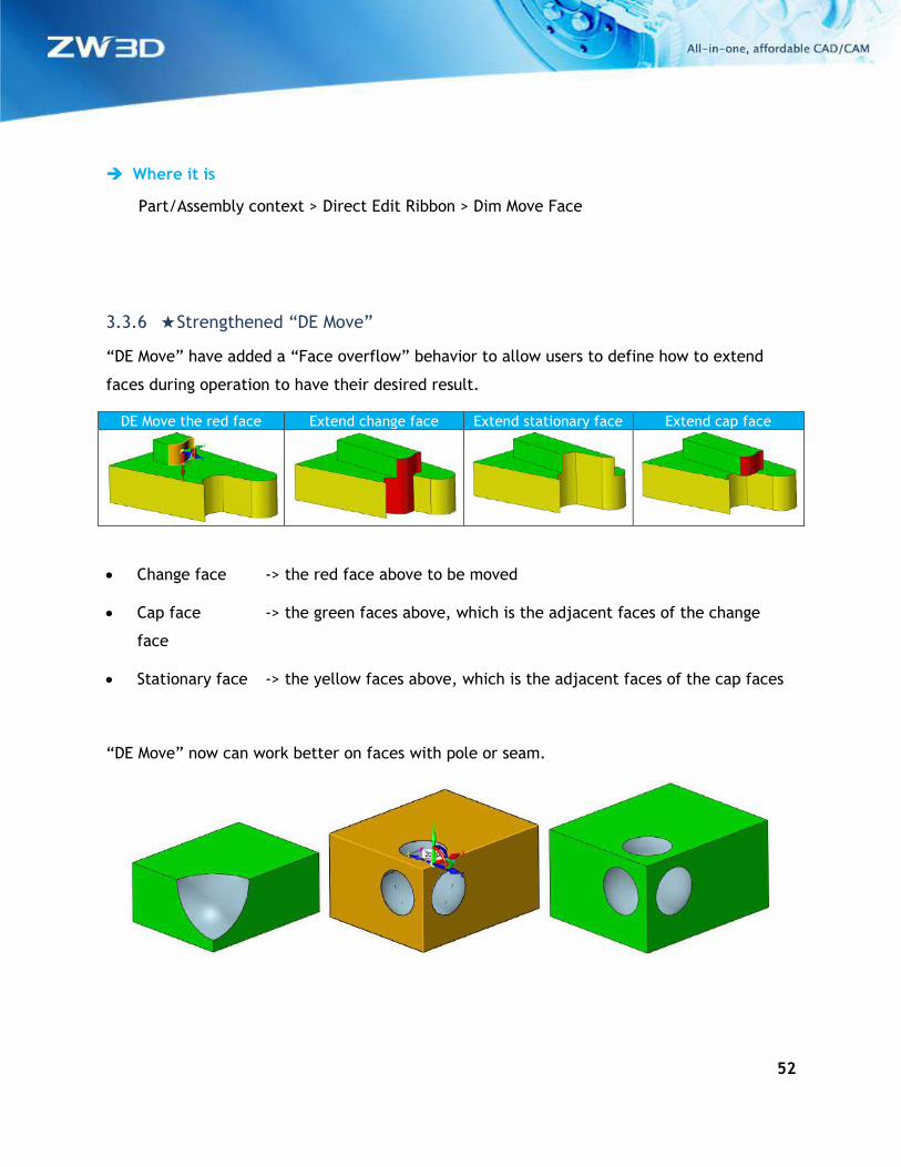
3.3.6 ★Strengthened “DE Move”
“DE Move” have added a “Face overflow” behavior to allow users to define how to extend
faces during operation to have their desired result.
DE Move the red face Extend change face Extend stationary face Extend cap face
• Change face -> the red face above to be moved
• Cap face -> the green faces above, which is the adjacent faces of the change
face
• Stationary face -> the yellow faces above, which is the adjacent faces of the cap faces
“DE Move” now can work better on faces with pole or seam.
53
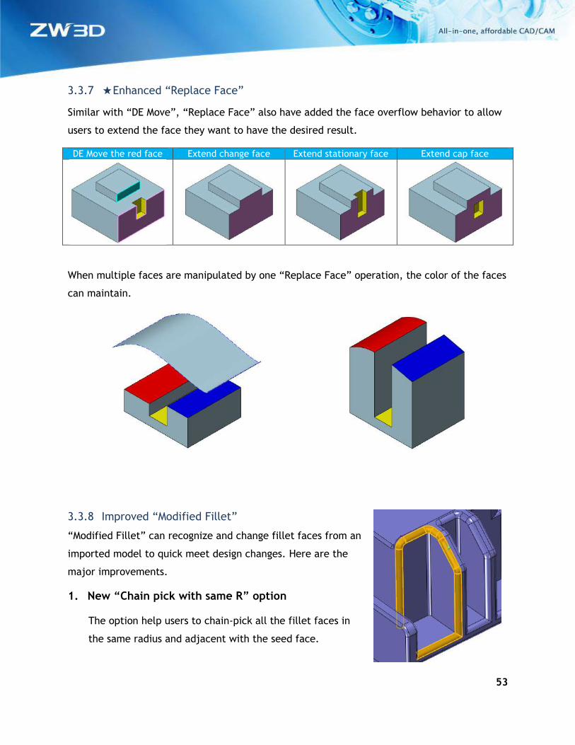
3.3.7 ★Enhanced “Replace Face”
Similar with “DE Move”, “Replace Face” also have added the face overflow behavior to allow
users to extend the face they want to have the desired result.
DE Move the red face Extend change face Extend stationary face Extend cap face
When multiple faces are manipulated by one “Replace Face” operation, the color of the faces
can maintain.
3.3.8 Improved “Modified Fillet”
“Modified Fillet” can recognize and change fillet faces from an
imported model to quick meet design changes. Here are the
major improvements.
1. New “Chain pick with same R” option
The option help users to chain-pick all the fillet faces in
the same radius and adjacent with the seed face.
54
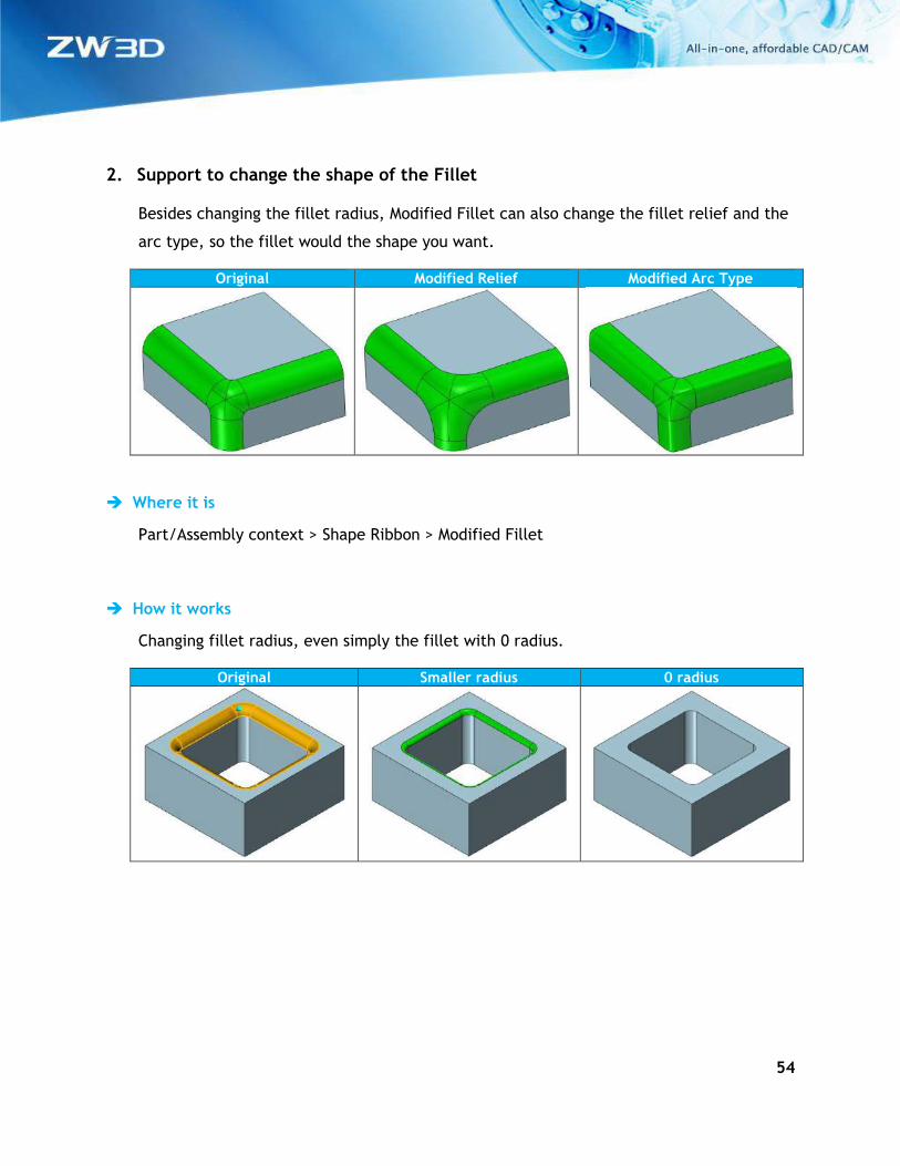
2. Support to change the shape of the Fillet
Besides changing the fillet radius, Modified Fillet can also change the fillet relief and the
arc type, so the fillet would the shape you want.
Original Modified Relief Modified Arc Type
Where it is
Part/Assembly context > Shape Ribbon > Modified Fillet
How it works
Changing fillet radius, even simply the fillet with 0 radius.
Original Smaller radius 0 radius
55
3.3.9 Expanded “Minimize surface data”
On previous version, “Minimize surface data” option can only be found on Morph related
commands. Now this option is available for most commands that create or modify free form
NURBS surfaces to further optimize surface data and reduce file size.
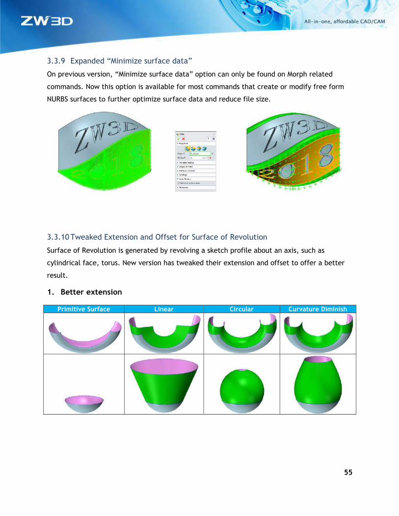
3.3.10 Tweaked Extension and Offset for Surface of Revolution
Surface of Revolution is generated by revolving a sketch profile about an axis, such as
cylindrical face, torus. New version has tweaked their extension and offset to offer a better
result.
1. Better extension
Primitive Surface Linear Circular Curvature Diminish
56
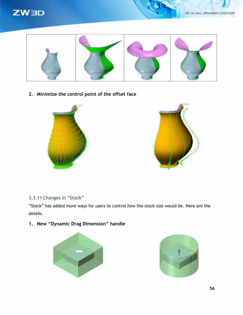
2. Minimize the control point of the offset face
3.3.11 Changes in “Stock”
“Stock” has added more ways for users to control how the stock size would be. Here are the
details.
1. New “Dynamic Drag Dimension” handle
57
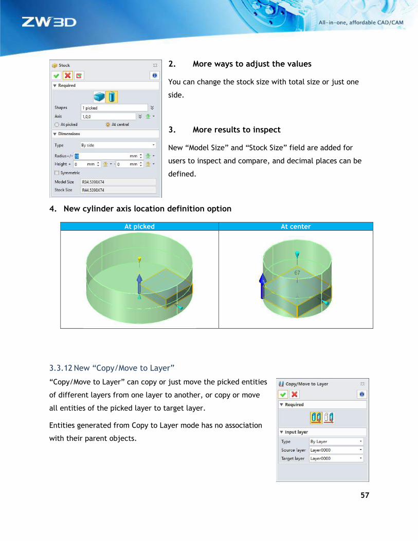
2. More ways to adjust the values
You can change the stock size with total size or just one
side.
3. More results to inspect
New “Model Size” and “Stock Size” field are added for
users to inspect and compare, and decimal places can be
defined.
4. New cylinder axis location definition option
At picked At center
3.3.12 New “Copy/Move to Layer”
“Copy/Move to Layer” can copy or just move the picked entities
of different layers from one layer to another, or copy or move
all entities of the picked layer to target layer.
Entities generated from Copy to Layer mode has no association
with their parent objects.
58
Where it is
Part/Assembly context > DA toolbar > Layer command group > Copy/Move to Layer
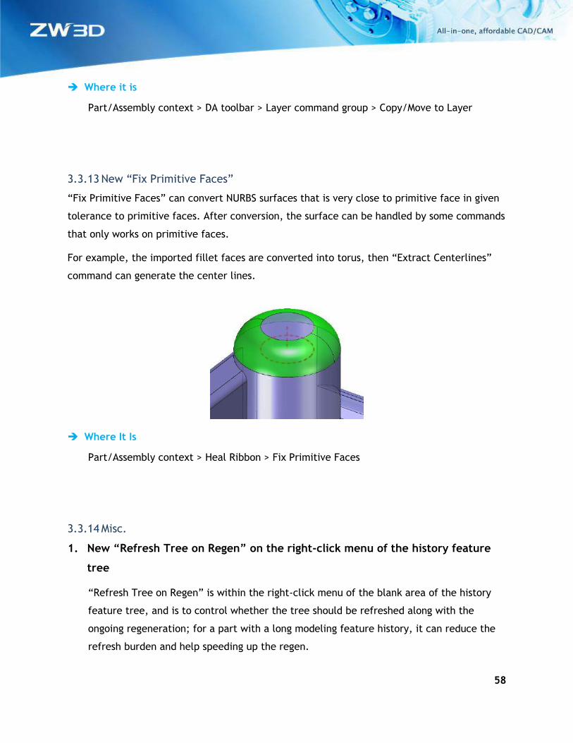
3.3.13 New “Fix Primitive Faces”
“Fix Primitive Faces” can convert NURBS surfaces that is very close to primitive face in given
tolerance to primitive faces. After conversion, the surface can be handled by some commands
that only works on primitive faces.
For example, the imported fillet faces are converted into torus, then “Extract Centerlines”
command can generate the center lines.
Where It Is
Part/Assembly context > Heal Ribbon > Fix Primitive Faces
3.3.14 Misc.
1. New “Refresh Tree on Regen” on the right-click menu of the history feature
tree
“Refresh Tree on Regen” is within the right-click menu of the blank area of the history
feature tree, and is to control whether the tree should be refreshed along with the
ongoing regeneration; for a part with a long modeling feature history, it can reduce the
refresh burden and help speeding up the regen.
59
2. New “Assign to layer” option in “Copy”
This option puts copied entities into the picked layer or a new layer, and only is available
when the “Associative copy” option is unchecked.
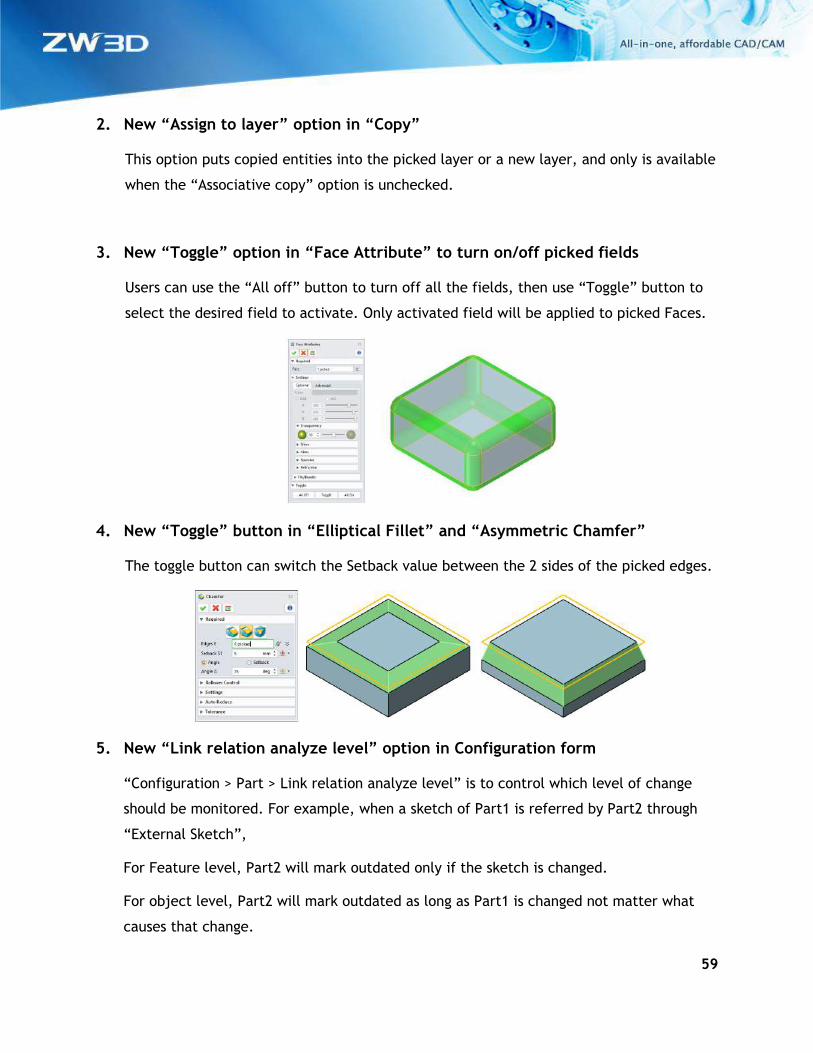
3. New “Toggle” option in “Face Attribute” to turn on/off picked fields
Users can use the “All off” button to turn off all the fields, then use “Toggle” button to
select the desired field to activate. Only activated field will be applied to picked Faces.
4. New “Toggle” button in “Elliptical Fillet” and “Asymmetric Chamfer”
The toggle button can switch the Setback value between the 2 sides of the picked edges.
5. New “Link relation analyze level” option in Configuration form
“Configuration > Part > Link relation analyze level” is to control which level of change
should be monitored. For example, when a sketch of Part1 is referred by Part2 through
“External Sketch”,
For Feature level, Part2 will mark outdated only if the sketch is changed.
For object level, Part2 will mark outdated as long as Part1 is changed not matter what
causes that change.
60
3.4 Assembly Design
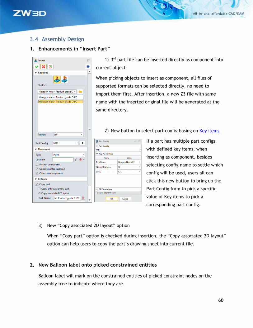
1. Enhancements in “Insert Part”
1) 3rd part file can be inserted directly as component into
current object
When picking objects to insert as component, all files of
supported formats can be selected directly, no need to
import them first. After insertion, a new Z3 file with same
name with the inserted original file will be generated at the
same directory.
2) New button to select part config basing on Key items
If a part has multiple part configs
with defined key items, when
inserting as component, besides
selecting config name to settle which
config will be used, users all can
click this new button to bring up the
Part Config form to pick a specific
value of Key items to pick a
corresponding part config.
3) New “Copy associated 2D layout” option
When “Copy part” option is checked during insertion, the “Copy associated 2D layout”
option can help users to copy the part’s drawing sheet into current file.
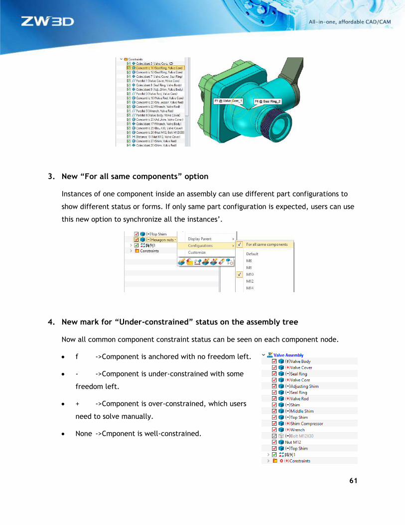
2. New Balloon label onto picked constrained entities
Balloon label will mark on the constrained entities of picked constraint nodes on the
assembly tree to indicate where they are.
61
3. New “For all same components” option
Instances of one component inside an assembly can use different part configurations to
show different status or forms. If only same part configuration is expected, users can use
this new option to synchronize all the instances’.
4. New mark for “Under-constrained” status on the assembly tree
Now all common component constraint status can be seen on each component node.
• f ->Component is anchored with no freedom left.
• - ->Component is under-constrained with some
freedom left.
• + ->Component is over-constrained, which users
need to solve manually.
• None ->Cmponent is well-constrained.
62
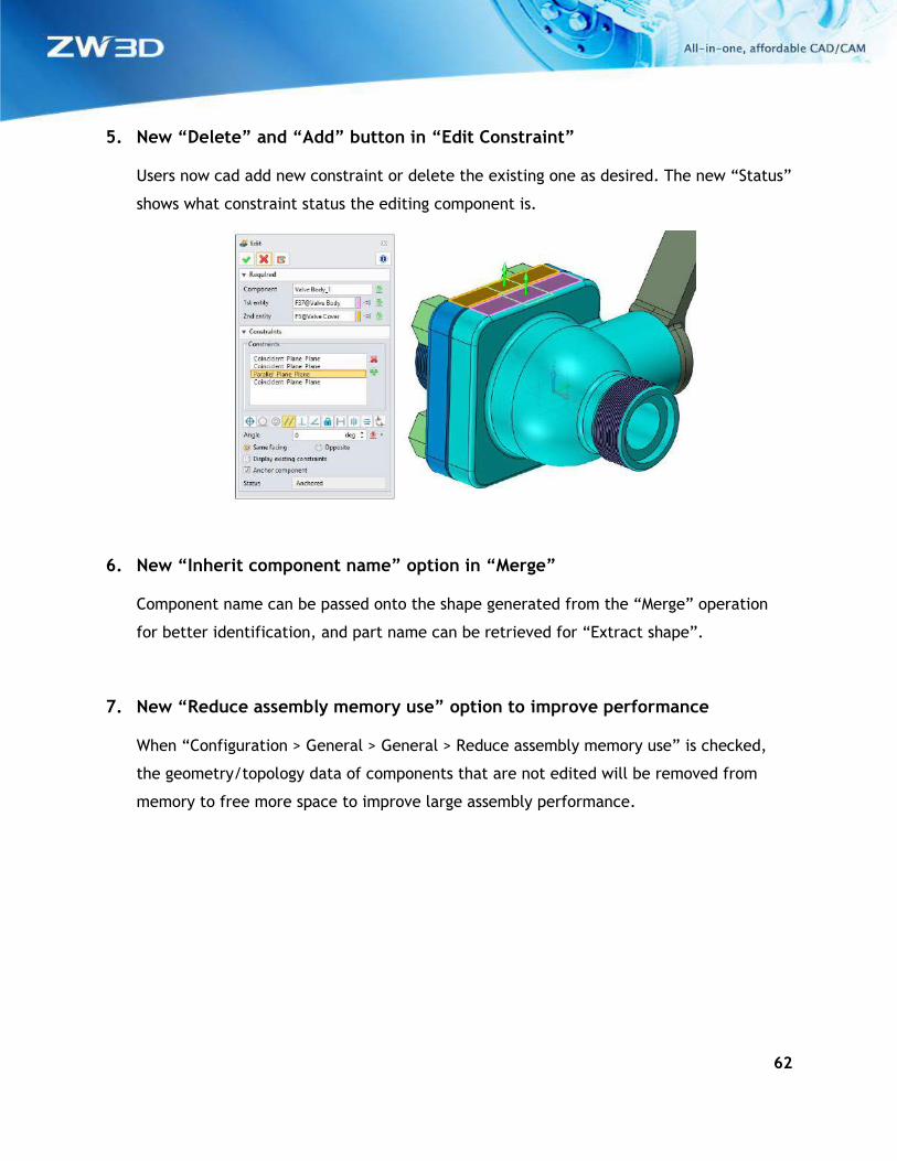
5. New “Delete” and “Add” button in “Edit Constraint”
Users now cad add new constraint or delete the existing one as desired. The new “Status”
shows what constraint status the editing component is.
6. New “Inherit component name” option in “Merge”
Component name can be passed onto the shape generated from the “Merge” operation
for better identification, and part name can be retrieved for “Extract shape”.
7. New “Reduce assembly memory use” option to improve performance
When “Configuration > General > General > Reduce assembly memory use” is checked,
the geometry/topology data of components that are not edited will be removed from
memory to free more space to improve large assembly performance.
63
3.5 Renewed Part Lib Design Tools
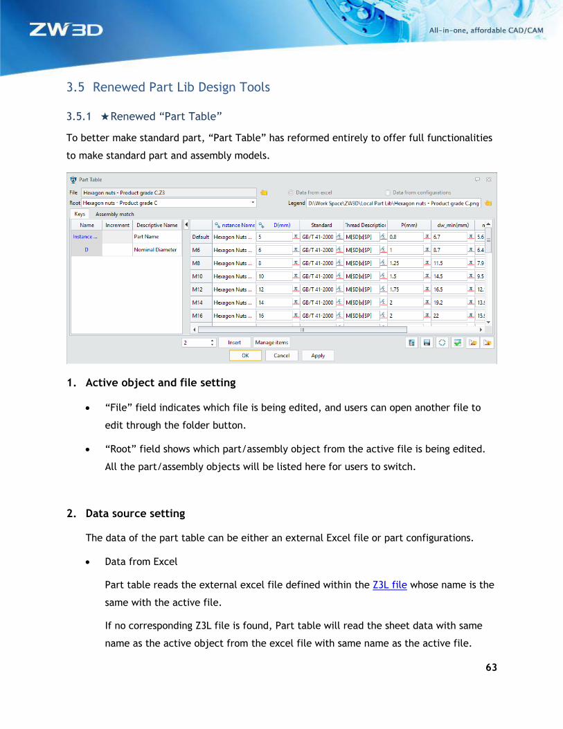
3.5.1 ★Renewed “Part Table”
To better make standard part, “Part Table” has reformed entirely to offer full functionalities
to make standard part and assembly models.
1. Active object and file setting
• “File” field indicates which file is being edited, and users can open another file to
edit through the folder button.
• “Root” field shows which part/assembly object from the active file is being edited.
All the part/assembly objects will be listed here for users to switch.
2. Data source setting
The data of the part table can be either an external Excel file or part configurations.
• Data from Excel
Part table reads the external excel file defined within the Z3L file whose name is the
same with the active file.
If no corresponding Z3L file is found, Part table will read the sheet data with same
name as the active object from the excel file with same name as the active file.
64
If no excel file is found, part table will ask users to make one if the option is picked.
• Data from configuration
Part table reads data from active object’s part configuration. If no configuration is
found, users can use the “Manage items” button to bring up the Part config form to
make one on the fly.
• If both external Excel and part configuration are available, the external Excel is the
first choice, but users can change it.
• If Z3L is defined, the source options above can’t be switched. Delete the Z3L file to
make those 2 option available if users want to change the source.
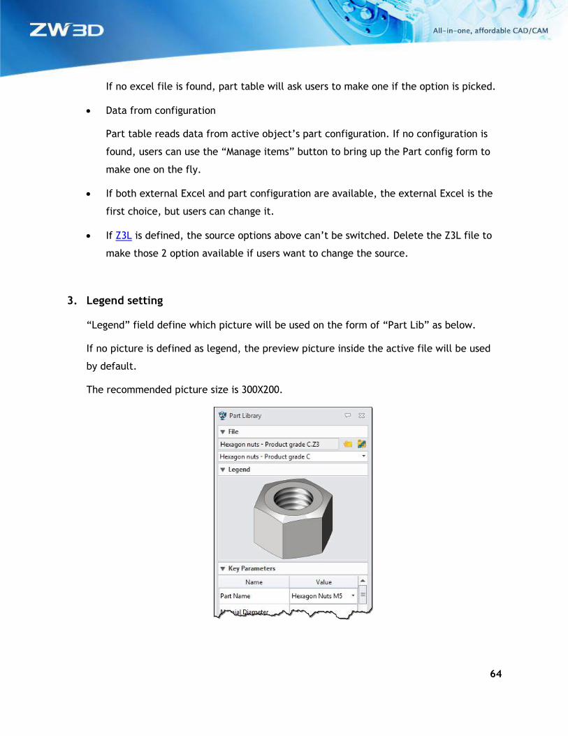
3. Legend setting
“Legend” field define which picture will be used on the form of “Part Lib” as below.
If no picture is defined as legend, the preview picture inside the active file will be used
by default.
The recommended picture size is 300X200.
65
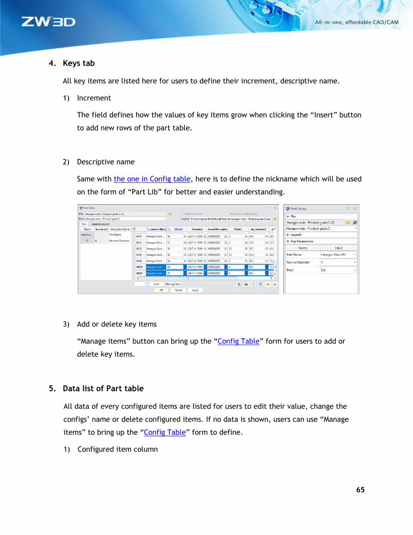
4. Keys tab
All key items are listed here for users to define their increment, descriptive name.
1) Increment
The field defines how the values of key items grow when clicking the “Insert” button
to add new rows of the part table.
2) Descriptive name
Same with the one in Config table, here is to define the nickname which will be used
on the form of “Part Lib” for better and easier understanding.
3) Add or delete key items
“Manage items” button can bring up the “Config Table” form for users to add or
delete key items.
5. Data list of Part table
All data of every configured items are listed for users to edit their value, change the
configs’ name or delete configured items. If no data is shown, users can use “Manage
items” to bring up the “Config Table” form to define.
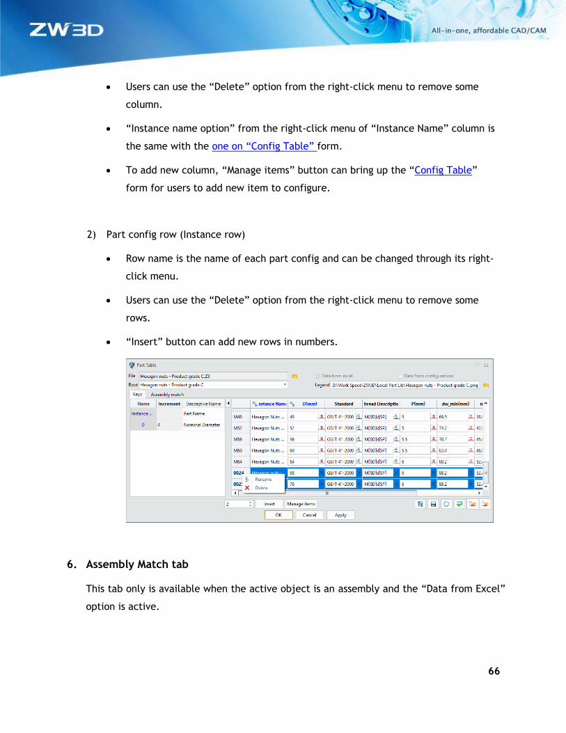
1) Configured item column
66
• Users can use the “Delete” option from the right-click menu to remove some
column.
• “Instance name option” from the right-click menu of “Instance Name” column is
the same with the one on “Config Table” form.
• To add new column, “Manage items” button can bring up the “Config Table”
form for users to add new item to configure.
2) Part config row (Instance row)
• Row name is the name of each part config and can be changed through its right-
click menu.
• Users can use the “Delete” option from the right-click menu to remove some
rows.
• “Insert” button can add new rows in numbers.
6. Assembly Match tab
This tab only is available when the active object is an assembly and the “Data from Excel”
option is active.
67
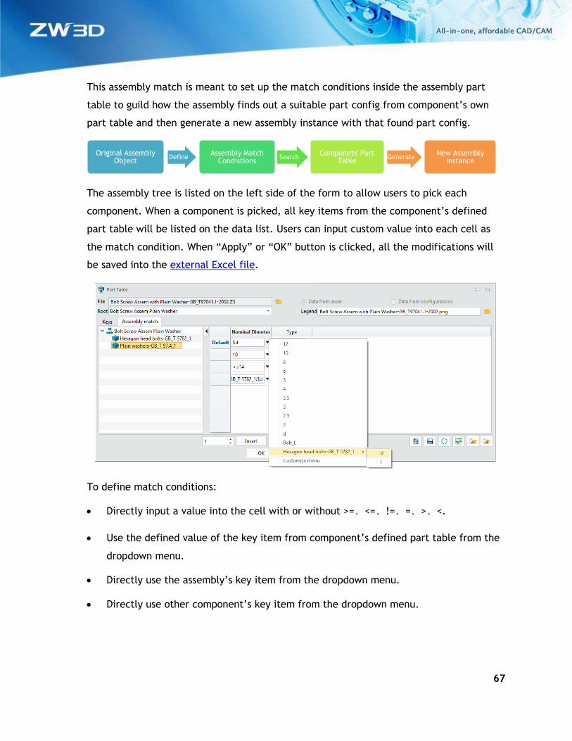
This assembly match is meant to set up the match conditions inside the assembly part
table to guild how the assembly finds out a suitable part config from component’s own
part table and then generate a new assembly instance with that found part config.
The assembly tree is listed on the left side of the form to allow users to pick each
component. When a component is picked, all key items from the component’s defined
part table will be listed on the data list. Users can input custom value into each cell as
the match condition. When “Apply” or “OK” button is clicked, all the modifications will
be saved into the external Excel file.
To define match conditions:
• Directly input a value into the cell with or without >=、<=、!=、=、>、<.
• Use the defined value of the key item from component’s defined part table from the
dropdown menu.
• Directly use the assembly’s key item from the dropdown menu.
• Directly use other component’s key item from the dropdown menu.
Original Assembly Object
DefineAssembly Match
CondistionsSearch
Componets' Part Table
GenerateNew Assembly
Instance
68
7. Z3L file
The Z3L file is generated by “Part Table” form to record the linkage among the active Z3
file, the legend picture and the data source. Its content looks like following.
#file=Bolt Screw Assem with Plain Washer-GB_T97041.1-2002.Z3|Bolt Screw Assem Plain Washer
#data=Bolt Screw Assem with Plain Washer-GB_T97041.1-2002.xlsx|Bolt Screw Assem Plain
Washer
#IMAGE=Bolt Screw Assem with Plain Washer-GB_T97041.1-2002.png
Z3L’s name has to be the same with the active file, and also saved into the same
directory, so that Part table can find it.
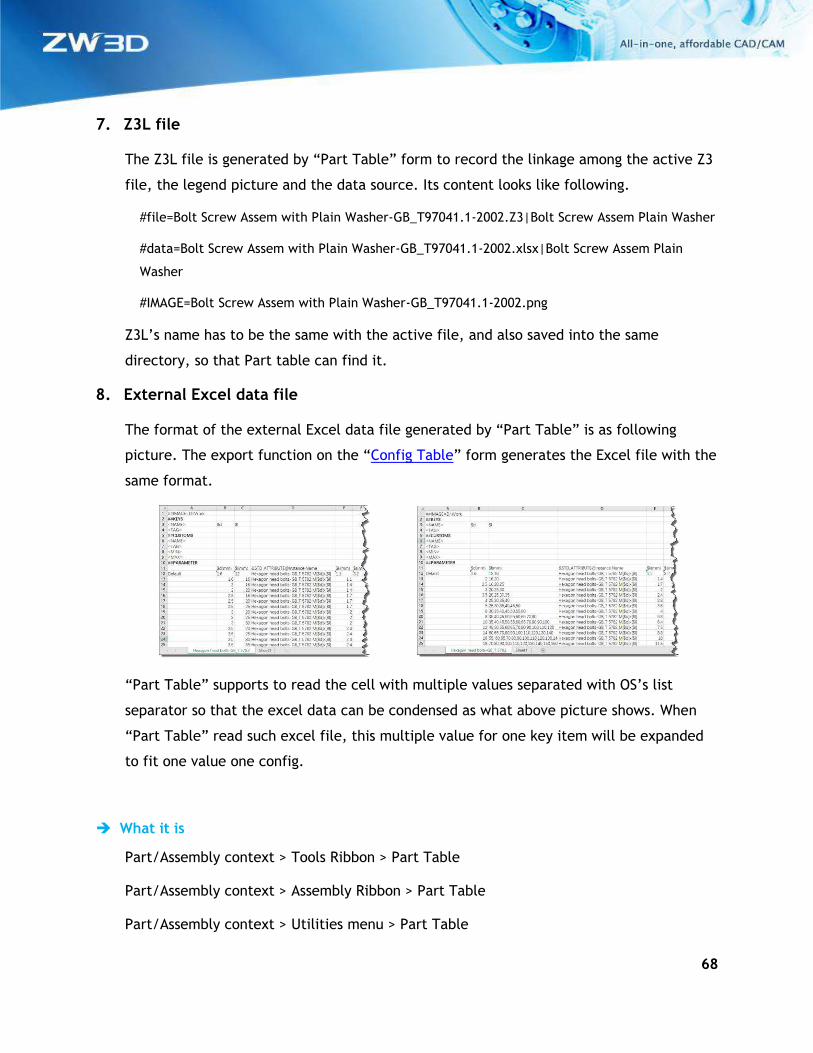
8. External Excel data file
The format of the external Excel data file generated by “Part Table” is as following
picture. The export function on the “Config Table” form generates the Excel file with the
same format.
“Part Table” supports to read the cell with multiple values separated with OS’s list
separator so that the excel data can be condensed as what above picture shows. When
“Part Table” read such excel file, this multiple value for one key item will be expanded
to fit one value one config.
What it is
Part/Assembly context > Tools Ribbon > Part Table
Part/Assembly context > Assembly Ribbon > Part Table
Part/Assembly context > Utilities menu > Part Table
69
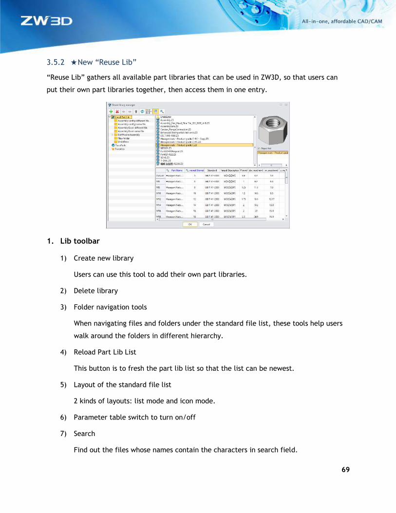
3.5.2 ★New “Reuse Lib”
“Reuse Lib” gathers all available part libraries that can be used in ZW3D, so that users can
put their own part libraries together, then access them in one entry.
1. Lib toolbar
1) Create new library
Users can use this tool to add their own part libraries.
2) Delete library
3) Folder navigation tools
When navigating files and folders under the standard file list, these tools help users
walk around the folders in different hierarchy.
4) Reload Part Lib List
This button is to fresh the part lib list so that the list can be newest.
5) Layout of the standard file list
2 kinds of layouts: list mode and icon mode.
6) Parameter table switch to turn on/off
7) Search
Find out the files whose names contain the characters in search field.
70
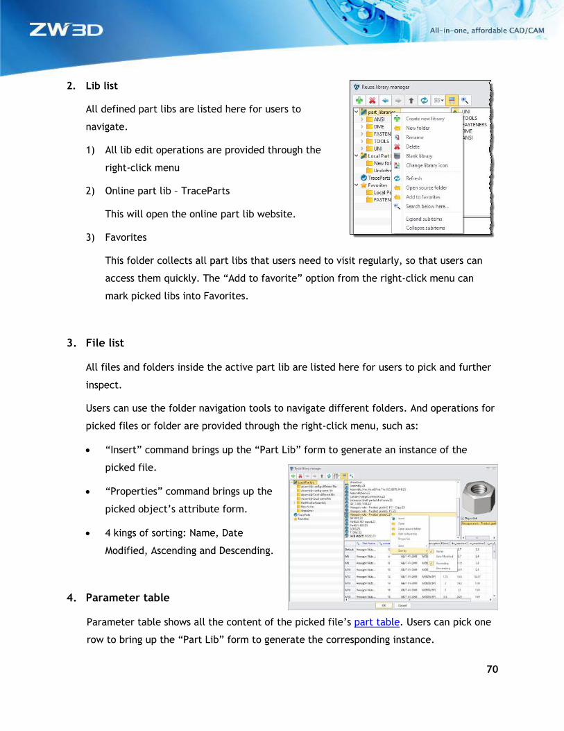
2. Lib list
All defined part libs are listed here for users to
navigate.
1) All lib edit operations are provided through the
right-click menu
2) Online part lib – TraceParts
This will open the online part lib website.
3) Favorites
This folder collects all part libs that users need to visit regularly, so that users can
access them quickly. The “Add to favorite” option from the right-click menu can
mark picked libs into Favorites.
3. File list
All files and folders inside the active part lib are listed here for users to pick and further
inspect.
Users can use the folder navigation tools to navigate different folders. And operations for
picked files or folder are provided through the right-click menu, such as:
• “Insert” command brings up the “Part Lib” form to generate an instance of the
picked file.
• “Properties” command brings up the
picked object’s attribute form.
• 4 kings of sorting: Name, Date
Modified, Ascending and Descending.
4. Parameter table
Parameter table shows all the content of the picked file’s part table. Users can pick one
row to bring up the “Part Lib” form to generate the corresponding instance.
71
What it is
Part/Assembly context > Tools Ribbon > Reuse Lib
Part/Assembly context > Assembly Ribbon > Reuse Lib
Part/Assembly context > Utilities menu > Reuse Lib
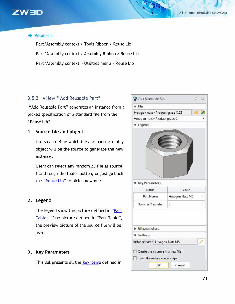
3.5.3 ★New “ Add Reusable Part”
“Add Reusable Part” generates an instance from a
picked specification of a standard file from the
“Reuse Lib”.
1. Source file and object
Users can define which file and part/assembly
object will be the source to generate the new
instance.
Users can select any random Z3 file as source
file through the folder button, or just go back
the “Reuse Lib” to pick a new one.
2. Legend
The legend show the picture defined in “Part
Table”. If no picture defined in “Part Table”,
the preview picture of the source file will be
used.
3. Key Parameters
This list presents all the key items defined in
72
“Config Table” or “Part Table”. Users settle which specification will be used to generate
the instance by selecting specific values of the key parameters.
4. Custom Parameters
This list presents all the custom items defined in “Config Table”. Double-click on the
value can activate the field to input new value.
5. All Parameters
All defined items in “Config Table” or “Part Table” can be listed out when check on
“Show all parameters” opiton.
6. Instance Name
This field reads out the defined “Instance Name” inside “Config Table” or “Part Table”. If
no “Instance Name” is defined, then the instance name will use the combination of
object name and config name.
Instance name can be defined to a custom one using the “Used define” button.
7. How to save the generated instance
There are 3 ways to save the instance:
• Check the “Create the instance in new file” option, the instance is generated in a
new individual Z3 file and saved.
• Uncheck the “Create the instance in new file” option, the instance is generated as a
new part object of the active file.
8. Where to save the generated instance
“Configuration > File > Create instance in working file” option defines where to save the
new instance.
73
If “Create instance in working file” option is checked, the instance is saved into the same
directory of the active file.
If the option is unchecked, the instance is saved into the defined directory which users
can modify.
9. How to inset the generated instance
When the “Insert the instance as a shape” option is checked, the instance is generated as
what the “Create instance in working file” option defines, then insert into active object
as the shape the “External Part” generates.
What it is
Part/Assembly context > Tools Ribbon > Reuse Lib > Click Ok after picking a file
Part/Assembly context > Assembly Ribbon > Reuse Lib > Click Ok after picking a file
Part/Assembly context > Utilities menu > Reuse Lib > Click Ok after picking a file
Part/Assembly context > Any instance on the assembly tree > right-click menu > Adjust
Component
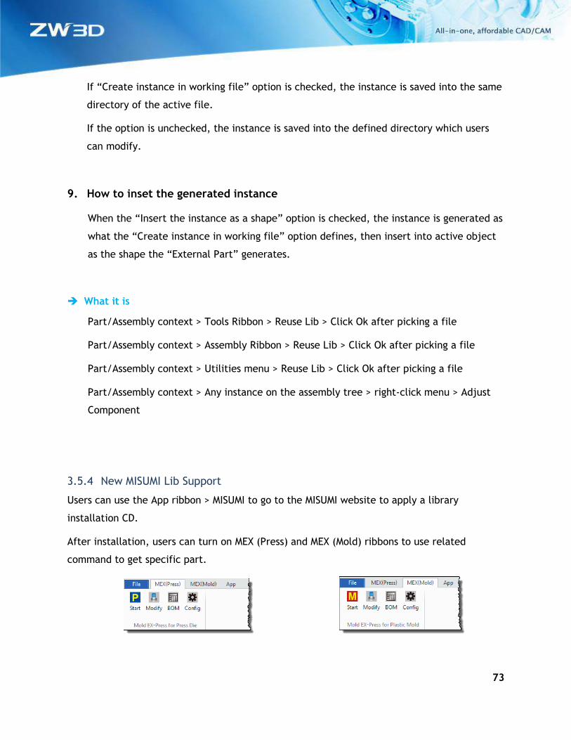
3.5.4 New MISUMI Lib Support
Users can use the App ribbon > MISUMI to go to the MISUMI website to apply a library
installation CD.
After installation, users can turn on MEX (Press) and MEX (Mold) ribbons to use related
command to get specific part.
74
3.6 ZWMold Design
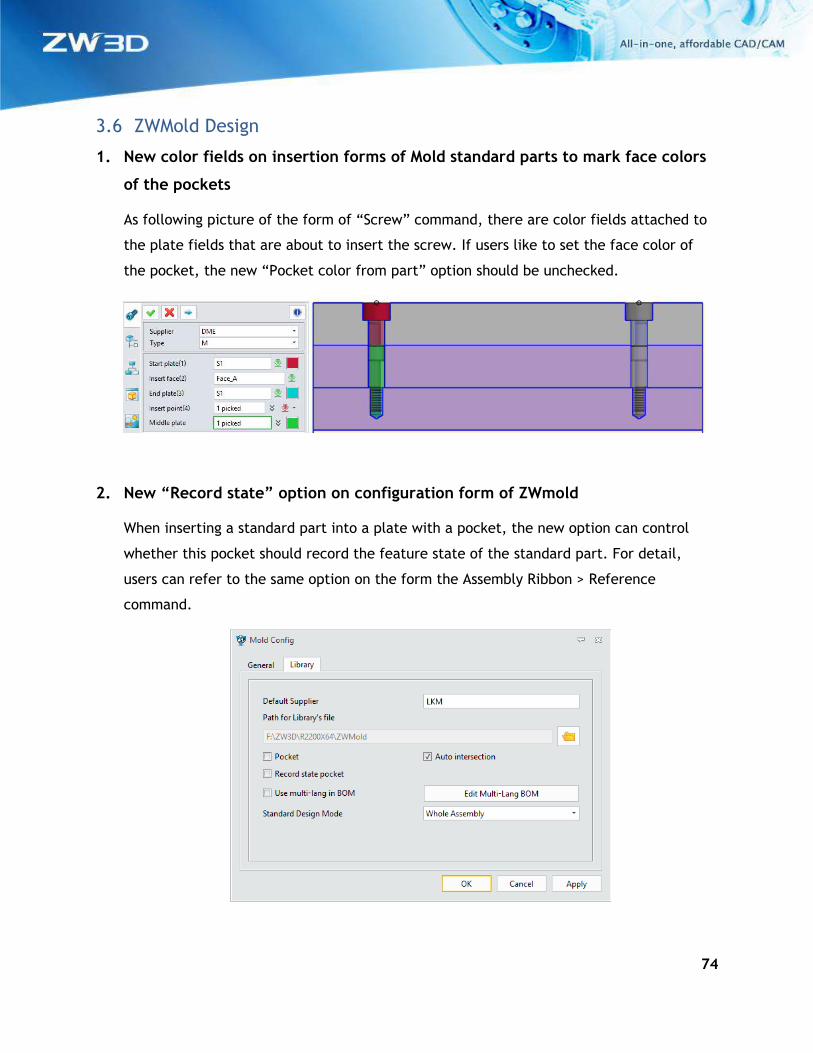
1. New color fields on insertion forms of Mold standard parts to mark face colors
of the pockets
As following picture of the form of “Screw” command, there are color fields attached to
the plate fields that are about to insert the screw. If users like to set the face color of
the pocket, the new “Pocket color from part” option should be unchecked.
2. New “Record state” option on configuration form of ZWmold
When inserting a standard part into a plate with a pocket, the new option can control
whether this pocket should record the feature state of the standard part. For detail,
users can refer to the same option on the form the Assembly Ribbon > Reference
command.
75
3.7 Drafting Design
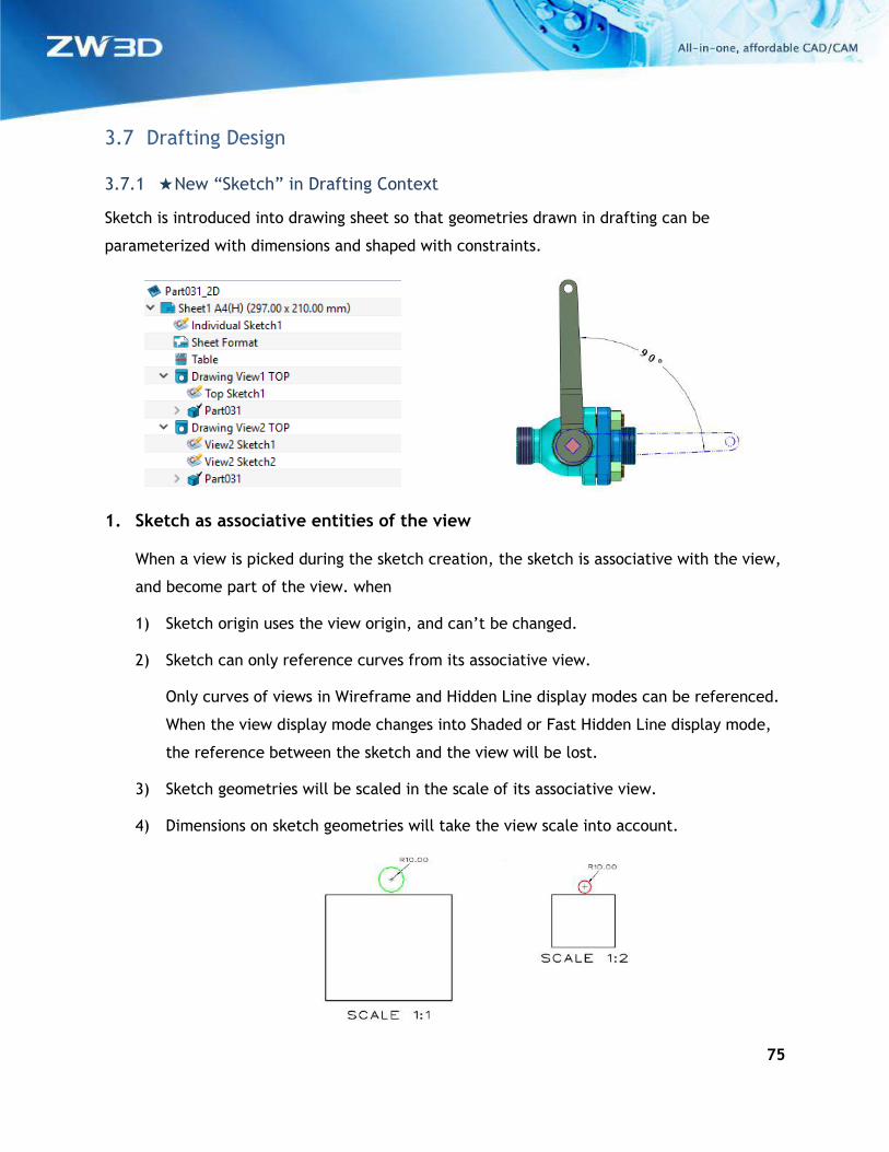
3.7.1 ★New “Sketch” in Drafting Context
Sketch is introduced into drawing sheet so that geometries drawn in drafting can be
parameterized with dimensions and shaped with constraints.
1. Sketch as associative entities of the view
When a view is picked during the sketch creation, the sketch is associative with the view,
and become part of the view. when
1) Sketch origin uses the view origin, and can’t be changed.
2) Sketch can only reference curves from its associative view.
Only curves of views in Wireframe and Hidden Line display modes can be referenced.
When the view display mode changes into Shaded or Fast Hidden Line display mode,
the reference between the sketch and the view will be lost.
3) Sketch geometries will be scaled in the scale of its associative view.
4) Dimensions on sketch geometries will take the view scale into account.
76
5) Only visible geometries except construction can be seen outside of the sketch.
6) One view can have multiple sketches.
2. Sketch as individual object
When no view is picked during sketch creation, then the sketch works as individual object.
1) The sheet origin will be the individual sketch origin.
2) Individual sketch takes the sheet scale as its own scale by default, but users can
customize it.
3) Individual sketch can’t reference any external geometries.
3. Sketch as elements of symbol
Sketch can be picked into a symbol. If a symbol containing a sketch is exploded, the
sketch becomes an individual sketch.
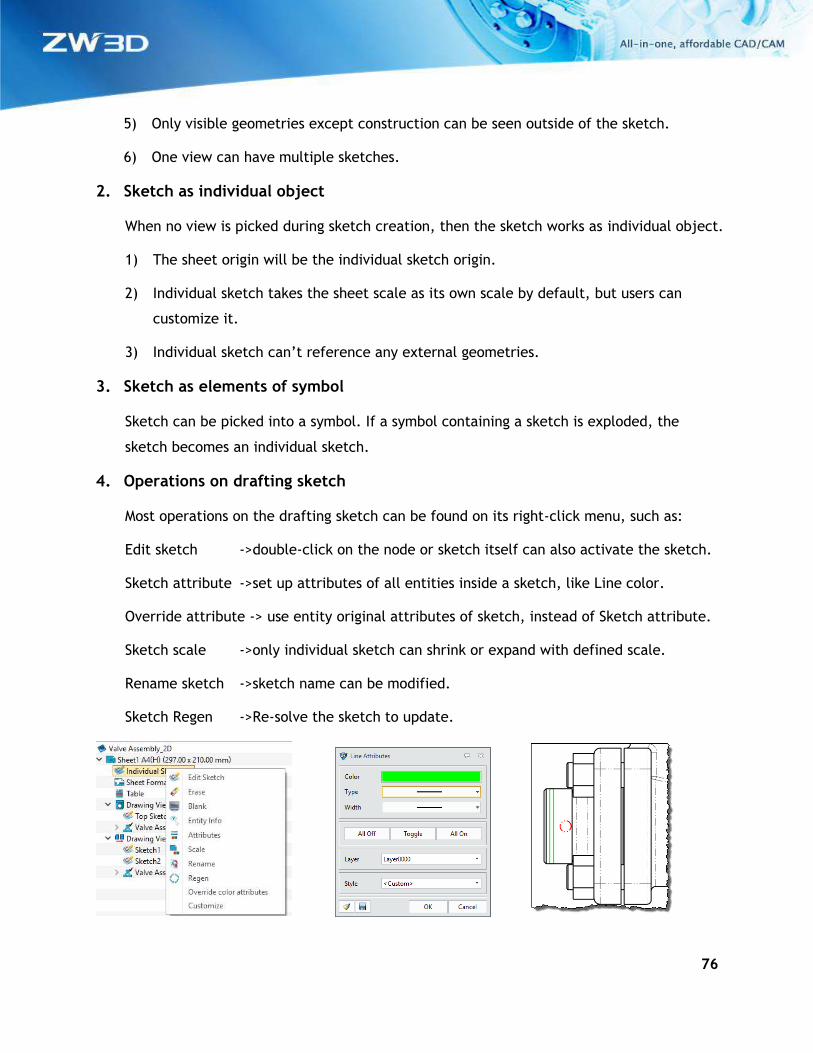
4. Operations on drafting sketch
Most operations on the drafting sketch can be found on its right-click menu, such as:
Edit sketch ->double-click on the node or sketch itself can also activate the sketch.
Sketch attribute ->set up attributes of all entities inside a sketch, like Line color.
Override attribute -> use entity original attributes of sketch, instead of Sketch attribute.
Sketch scale ->only individual sketch can shrink or expand with defined scale.
Rename sketch ->sketch name can be modified.
Sketch Regen ->Re-solve the sketch to update.
77
What it is
Drafting context > Drawing Ribbon > Sketch
Drafting context > Right-click menu on a view node > Create a sketch
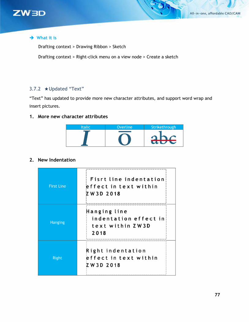
3.7.2 ★Updated “Text”
“Text” has updated to provide more new character attributes, and support word wrap and
insert pictures.
1. More new character attributes
Italic Overline Strikethrough
2. New Indentation
First Line
Hanging
Right
78
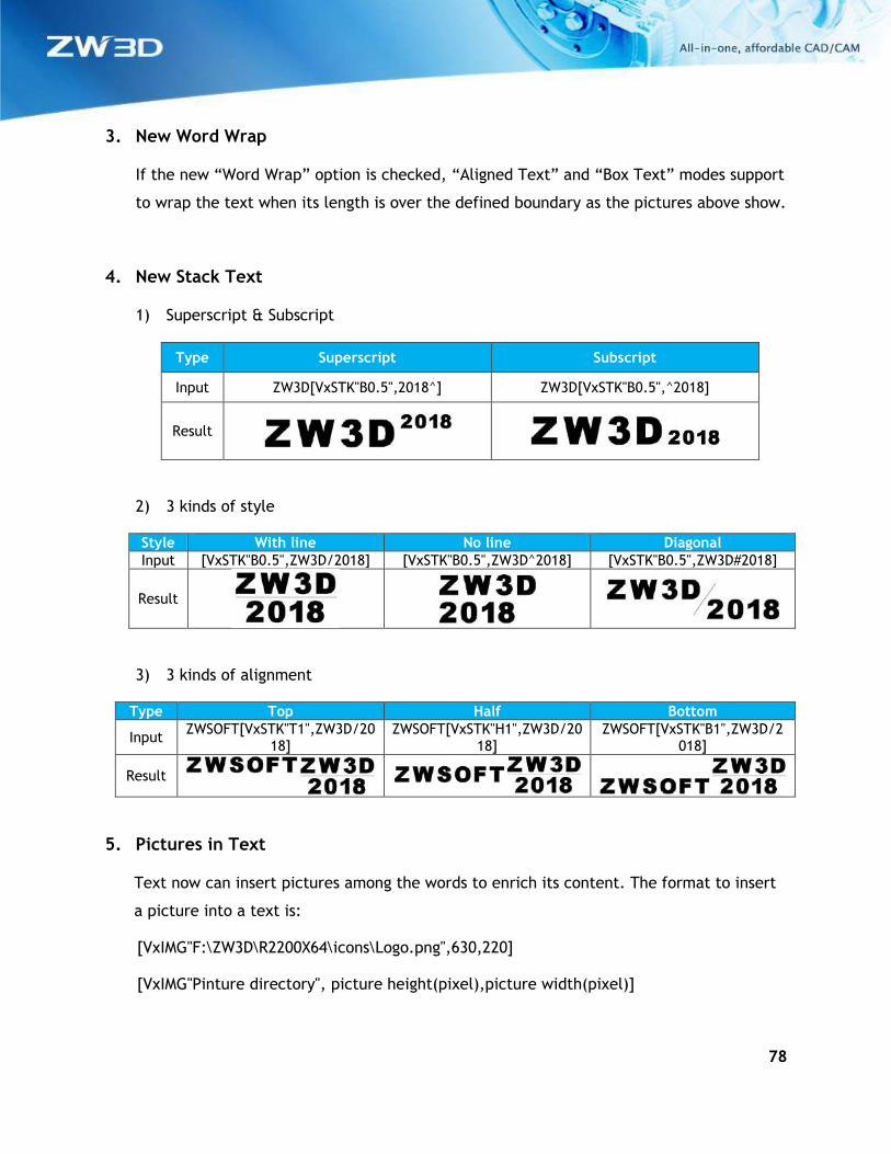
3. New Word Wrap
If the new “Word Wrap” option is checked, “Aligned Text” and “Box Text” modes support
to wrap the text when its length is over the defined boundary as the pictures above show.
4. New Stack Text
1) Superscript & Subscript
Type Superscript Subscript
Input ZW3D[VxSTK"B0.5",2018^] ZW3D[VxSTK"B0.5",^2018]
Result
2) 3 kinds of style
Style With line No line Diagonal
Input [VxSTK"B0.5",ZW3D/2018] [VxSTK"B0.5",ZW3D^2018] [VxSTK"B0.5",ZW3D#2018]
Result
3) 3 kinds of alignment
Type Top Half Bottom
Input ZWSOFT[VxSTK"T1",ZW3D/20
18] ZWSOFT[VxSTK"H1",ZW3D/20
18] ZWSOFT[VxSTK"B1",ZW3D/2
018]
Result
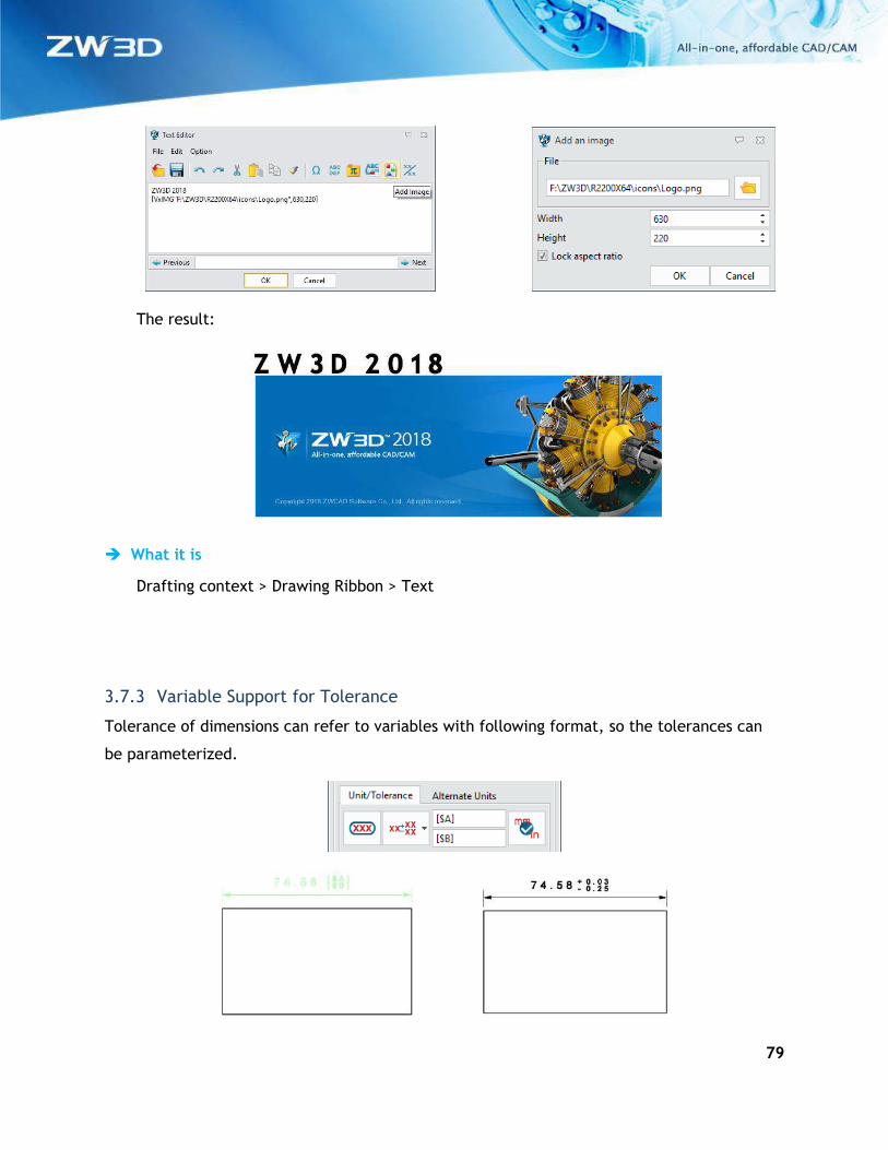
5. Pictures in Text
Text now can insert pictures among the words to enrich its content. The format to insert
a picture into a text is:
[VxIMG"F:\ZW3D\R2200X64\icons\Logo.png",630,220]
[VxIMG"Pinture directory", picture height(pixel),picture width(pixel)]
79
The result:
What it is
Drafting context > Drawing Ribbon > Text
3.7.3 Variable Support for Tolerance
Tolerance of dimensions can refer to variables with following format, so the tolerances can
be parameterized.
80
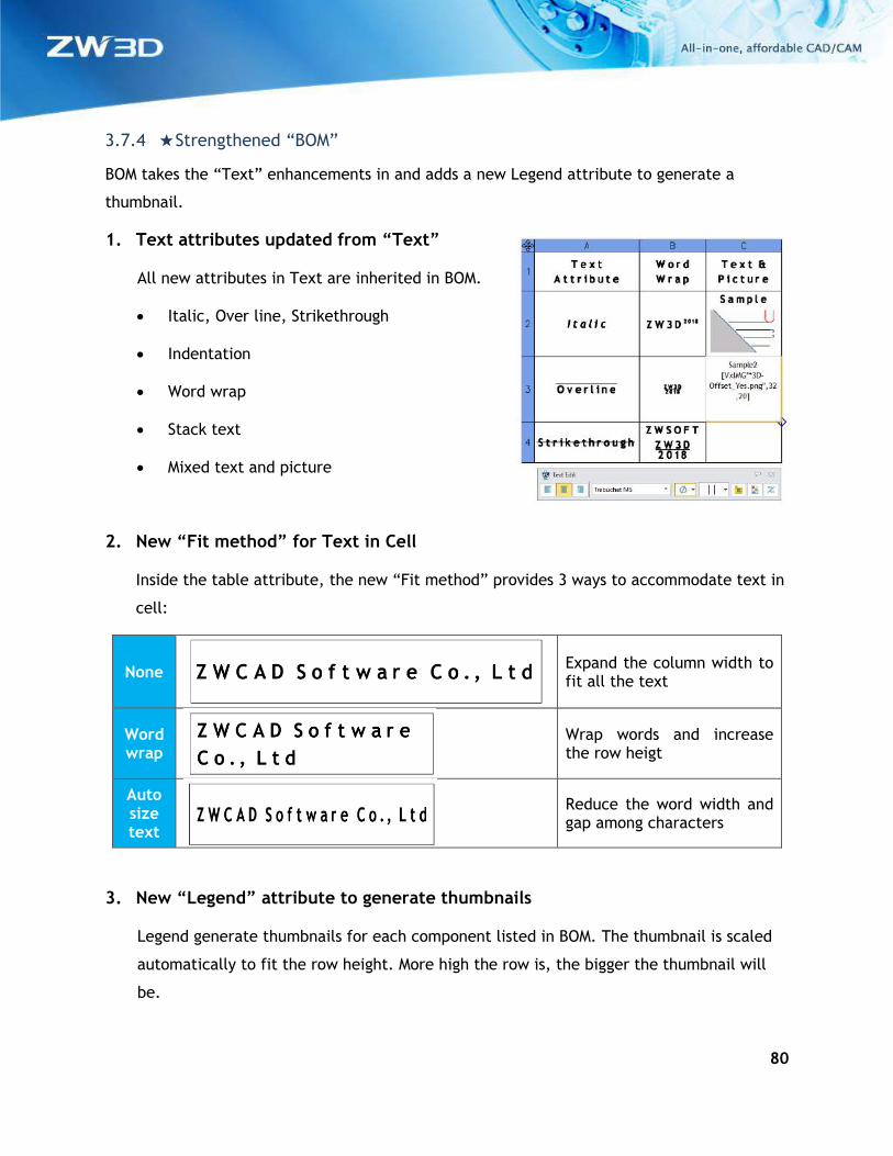
3.7.4 ★Strengthened “BOM”
BOM takes the “Text” enhancements in and adds a new Legend attribute to generate a
thumbnail.
1. Text attributes updated from “Text”
All new attributes in Text are inherited in BOM.
• Italic, Over line, Strikethrough
• Indentation
• Word wrap
• Stack text
• Mixed text and picture
2. New “Fit method” for Text in Cell
Inside the table attribute, the new “Fit method” provides 3 ways to accommodate text in
cell:
None
Expand the column width to fit all the text
Word wrap
Wrap words and increase the row heigt
Auto size text
Reduce the word width and gap among characters
3. New “Legend” attribute to generate thumbnails
Legend generate thumbnails for each component listed in BOM. The thumbnail is scaled
automatically to fit the row height. More high the row is, the bigger the thumbnail will
be.
81
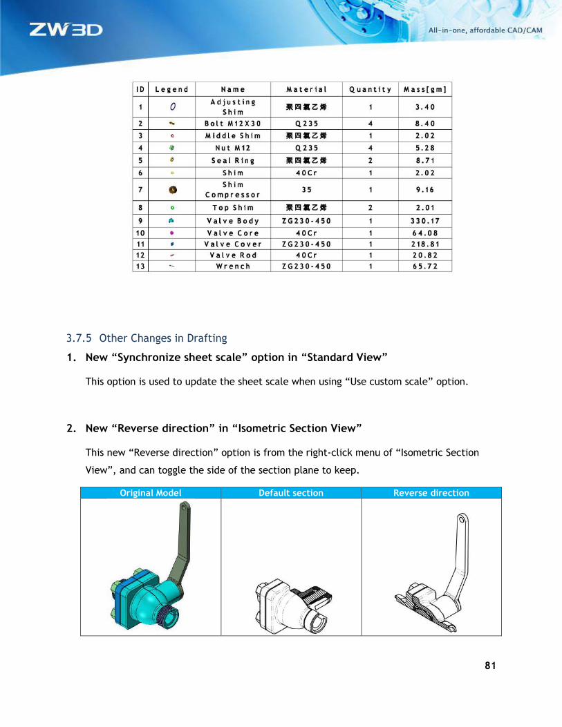
3.7.5 Other Changes in Drafting
1. New “Synchronize sheet scale” option in “Standard View”
This option is used to update the sheet scale when using “Use custom scale” option.
2. New “Reverse direction” in “Isometric Section View”
This new “Reverse direction” option is from the right-click menu of “Isometric Section
View”, and can toggle the side of the section plane to keep.
Original Model Default section Reverse direction
82
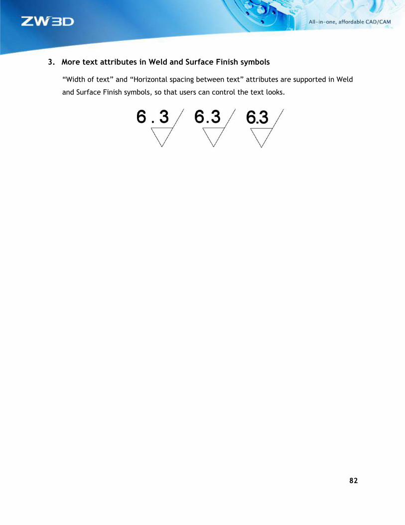
3. More text attributes in Weld and Surface Finish symbols
“Width of text” and “Horizontal spacing between text” attributes are supported in Weld
and Surface Finish symbols, so that users can control the text looks.
83
4 CAM
4.1 Summary of CAM New Features
ZW3D CAM contains 2~5aixs machining modules with flexible and rich milling strategies. It’s
an easy to learn and easy to use NC CAM software which is widely used in tool making,
automotive industry, and mold industry. This document describes the most significant
improvements of ZW3D 2018 version. ZW3D 2018 contains the following new features and
enhancements in CAM module:
1) New Shape Modify Function in Surface Feature – User can use this option to set
different thickness for different surfaces in a machining part, so as to achieve special
machining purpose.
2) 5-Axis Point Control Option and 3X to 5X Undercut Option in Z Level and Offset 3D
3) New Along Tool Axis Option in 5X Plane Cut and Guide Surface ISO Cut Options
4) New Side Steps Function in 5X Side Cut Operation
5) New Frame Option in Flat Finish Operation
6) Misc. – some enhancements to users’ work more efficient and more stable, such as:
A. New Total Time Function in Setup
B. New Z Min, Z Max and Total Time Entries in Spreadsheet Interface – Operation
View
C. New Frame Attribute in Frame Function
D. New Frame Option in Flat Region Feature
84
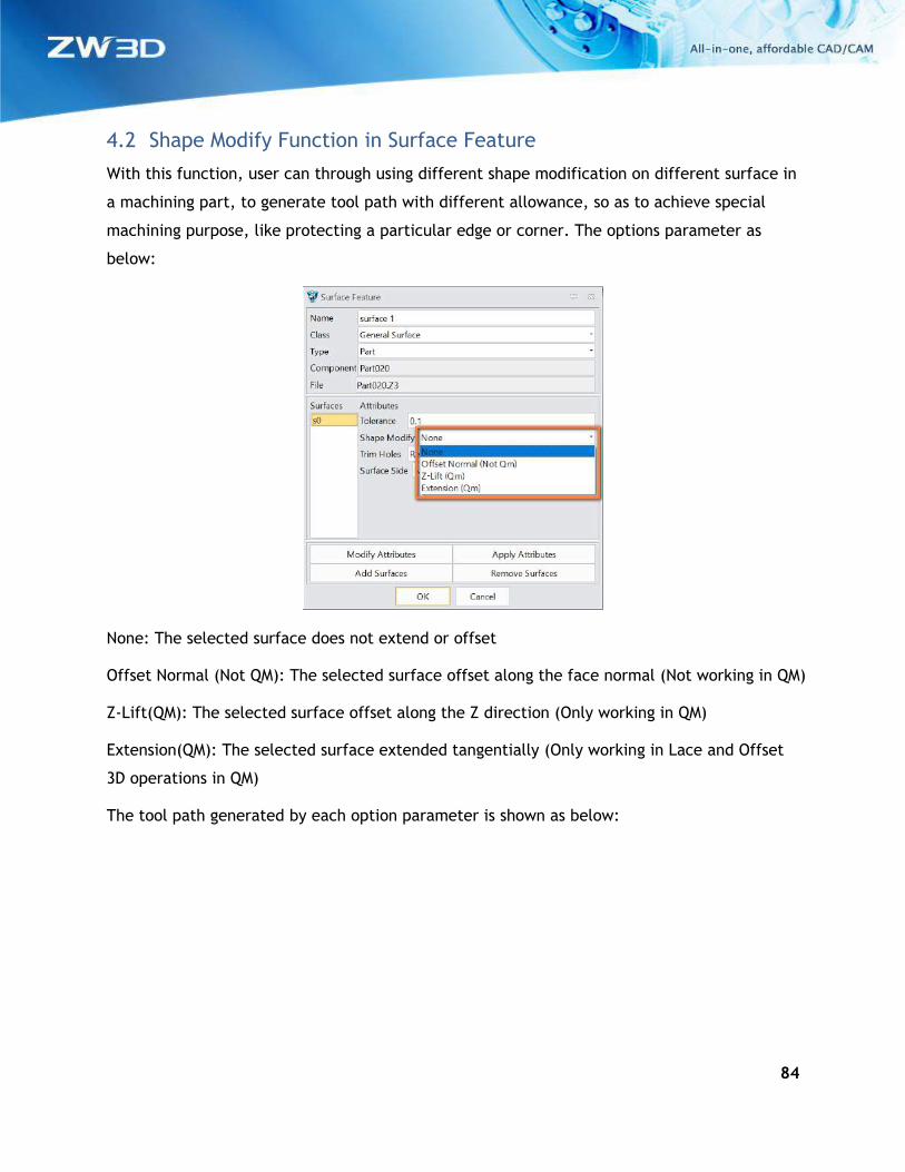
4.2 Shape Modify Function in Surface Feature
With this function, user can through using different shape modification on different surface in
a machining part, to generate tool path with different allowance, so as to achieve special
machining purpose, like protecting a particular edge or corner. The options parameter as
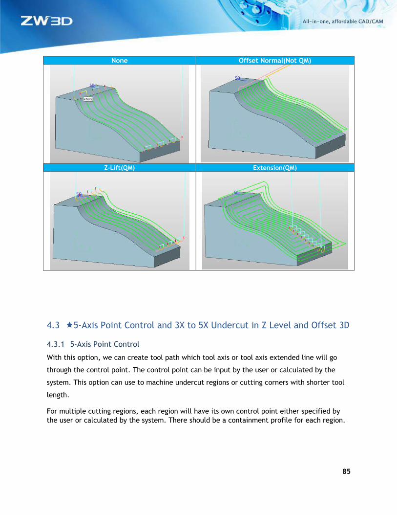
below:
None: The selected surface does not extend or offset
Offset Normal (Not QM): The selected surface offset along the face normal (Not working in QM)
Z-Lift(QM): The selected surface offset along the Z direction (Only working in QM)
Extension(QM): The selected surface extended tangentially (Only working in Lace and Offset
3D operations in QM)
The tool path generated by each option parameter is shown as below:
85
None Offset Normal(Not QM)
Z-Lift(QM) Extension(QM)
4.3 5-Axis Point Control and 3X to 5X Undercut in Z Level and Offset 3D
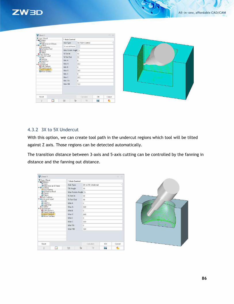
4.3.1 5-Axis Point Control
With this option, we can create tool path which tool axis or tool axis extended line will go
through the control point. The control point can be input by the user or calculated by the
system. This option can use to machine undercut regions or cutting corners with shorter tool
length.
For multiple cutting regions, each region will have its own control point either specified by
the user or calculated by the system. There should be a containment profile for each region.
86
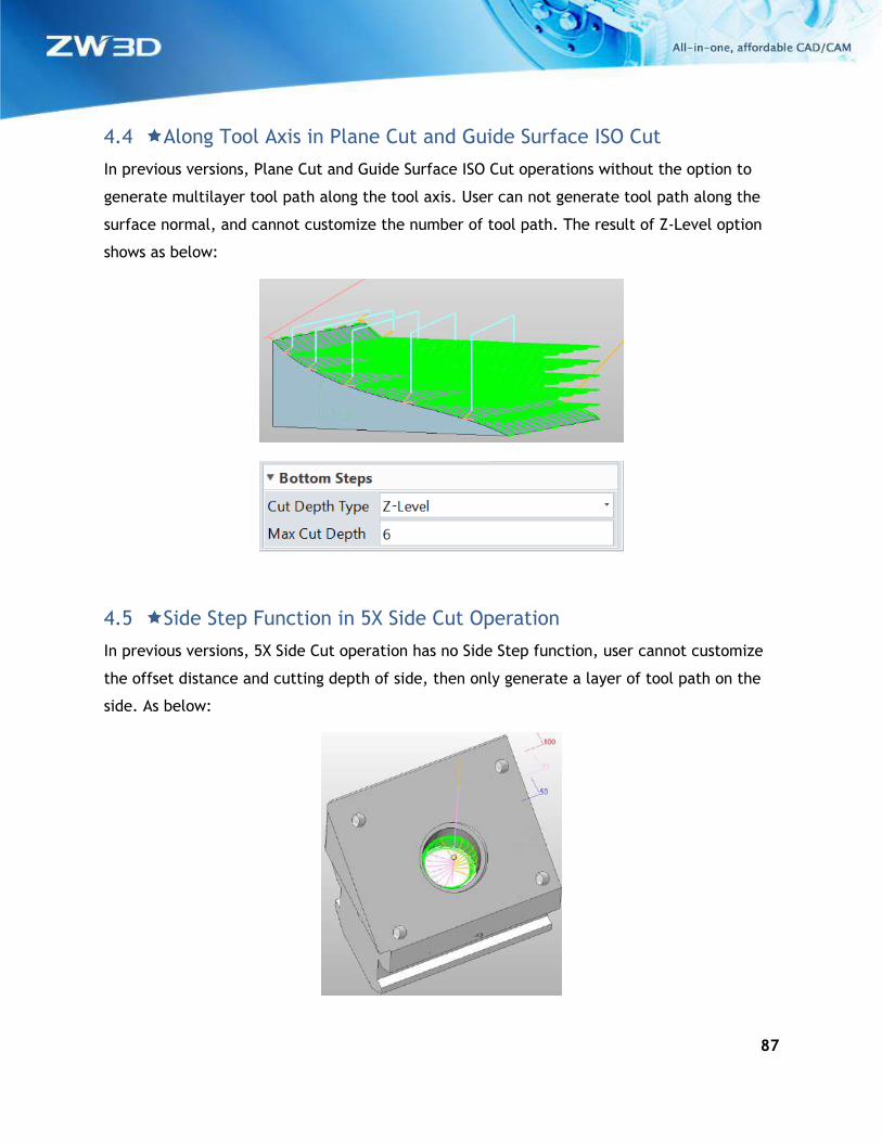
4.3.2 3X to 5X Undercut
With this option, we can create tool path in the undercut regions which tool will be tilted
against Z axis. Those regions can be detected automatically.
The transition distance between 3-axis and 5-axis cutting can be controlled by the fanning in
distance and the fanning out distance.
87
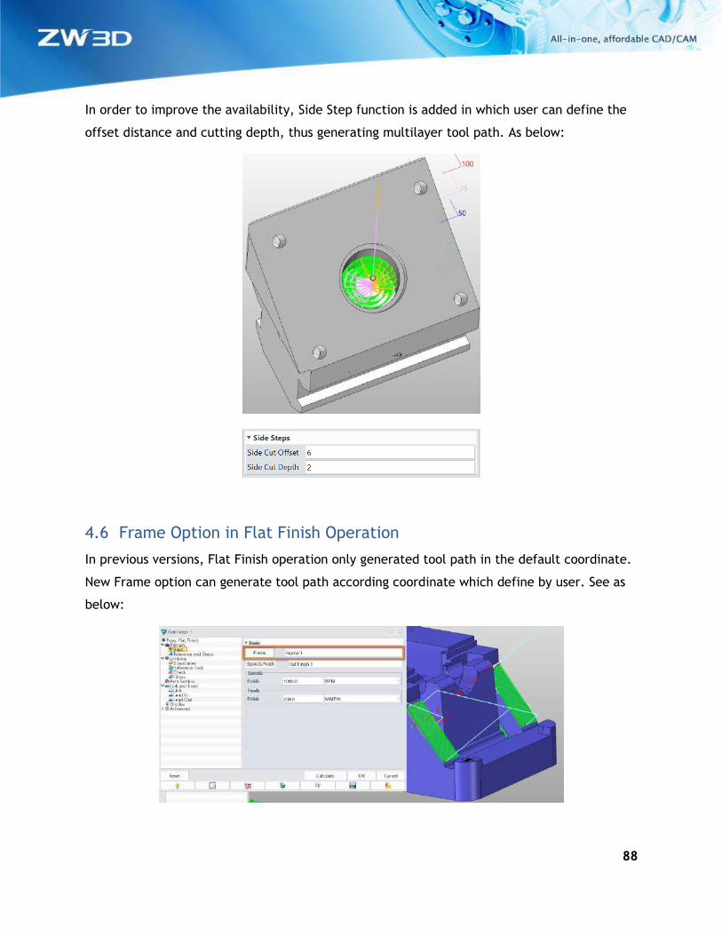
4.4 Along Tool Axis in Plane Cut and Guide Surface ISO Cut
In previous versions, Plane Cut and Guide Surface ISO Cut operations without the option to
generate multilayer tool path along the tool axis. User can not generate tool path along the
surface normal, and cannot customize the number of tool path. The result of Z-Level option
shows as below:
4.5 Side Step Function in 5X Side Cut Operation
In previous versions, 5X Side Cut operation has no Side Step function, user cannot customize
the offset distance and cutting depth of side, then only generate a layer of tool path on the
side. As below:
88
In order to improve the availability, Side Step function is added in which user can define the
offset distance and cutting depth, thus generating multilayer tool path. As below:
4.6 Frame Option in Flat Finish Operation
In previous versions, Flat Finish operation only generated tool path in the default coordinate.
New Frame option can generate tool path according coordinate which define by user. See as
below:
89
4.7 Misc. – some enhancements to users’ work more efficient and more
stable
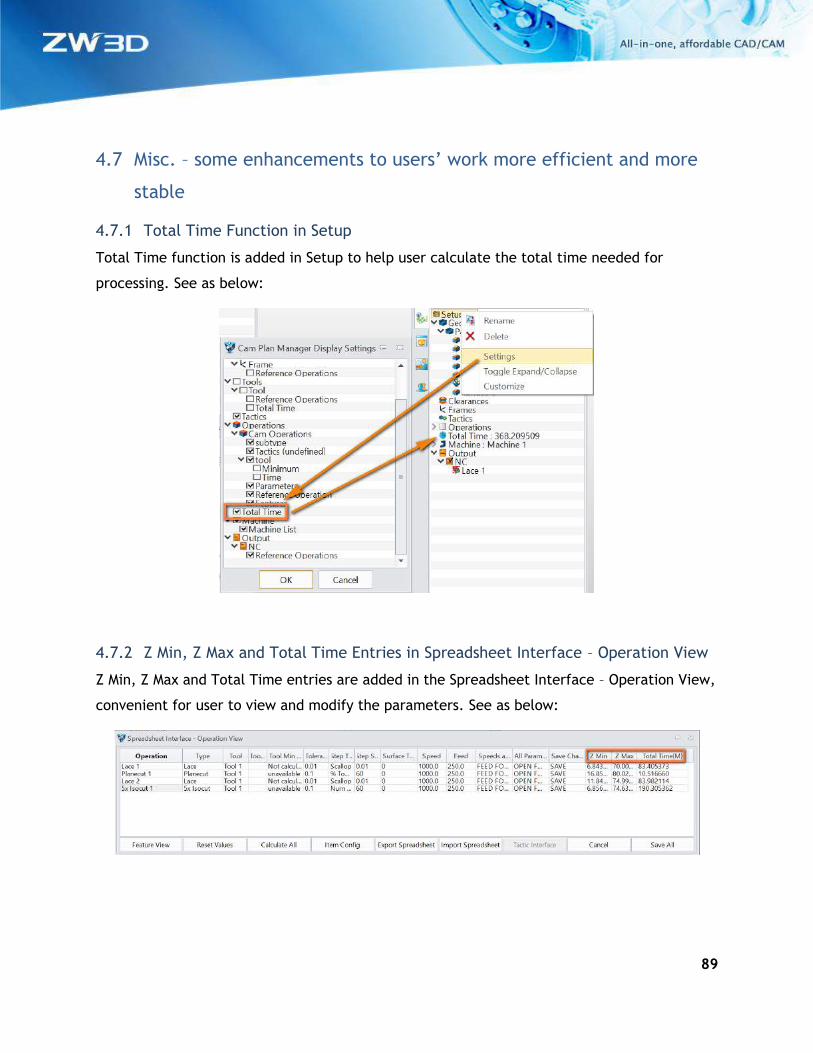
4.7.1 Total Time Function in Setup
Total Time function is added in Setup to help user calculate the total time needed for
processing. See as below:
4.7.2 Z Min, Z Max and Total Time Entries in Spreadsheet Interface – Operation View
Z Min, Z Max and Total Time entries are added in the Spreadsheet Interface – Operation View,
convenient for user to view and modify the parameters. See as below:
90
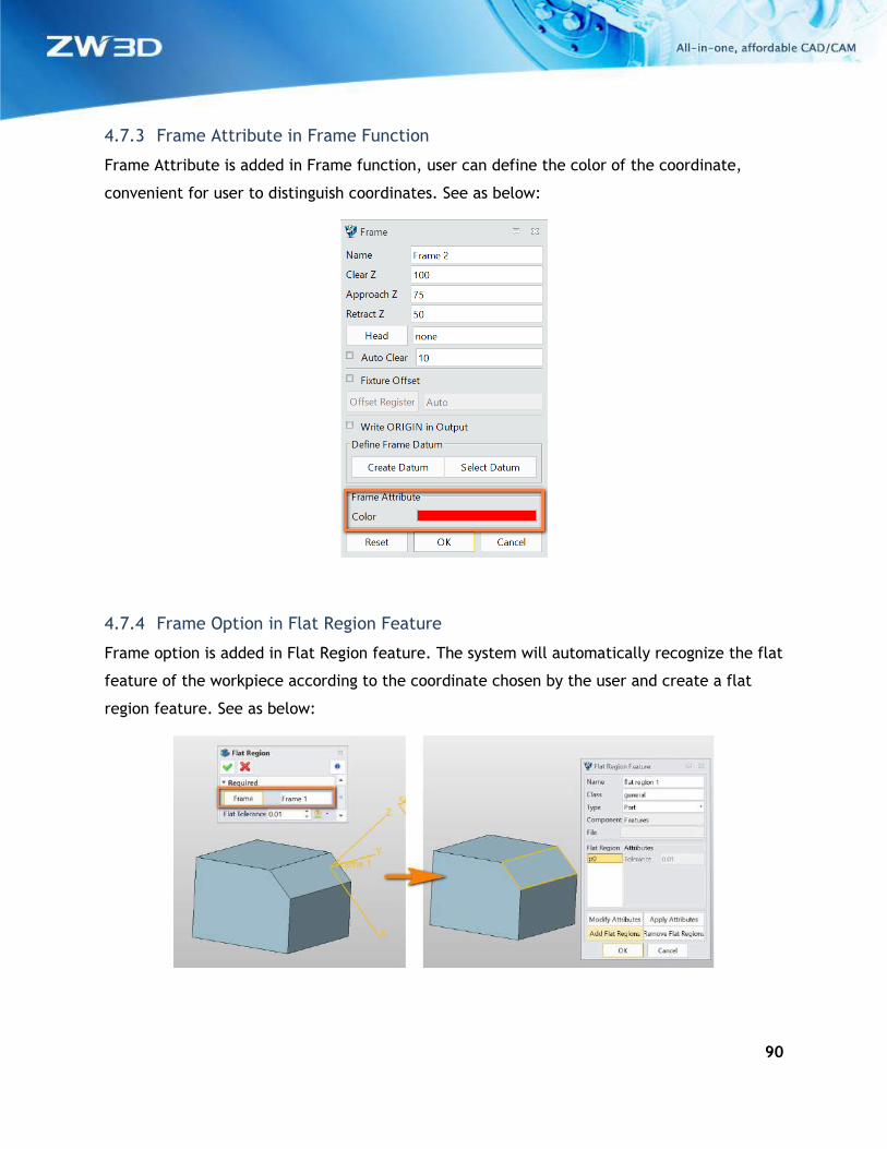
4.7.3 Frame Attribute in Frame Function
Frame Attribute is added in Frame function, user can define the color of the coordinate,
convenient for user to distinguish coordinates. See as below:
4.7.4 Frame Option in Flat Region Feature
Frame option is added in Flat Region feature. The system will automatically recognize the flat
feature of the workpiece according to the coordinate chosen by the user and create a flat
region feature. See as below:
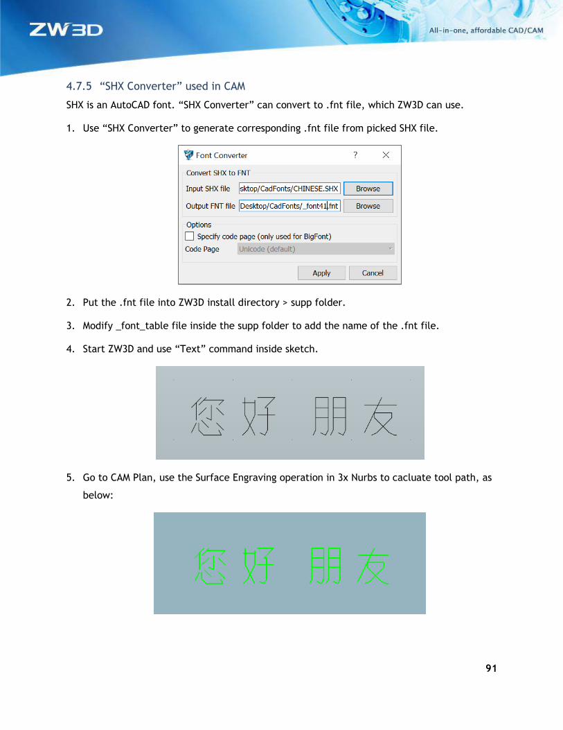
91
4.7.5 “SHX Converter” used in CAM
SHX is an AutoCAD font. “SHX Converter” can convert to .fnt file, which ZW3D can use.
1. Use “SHX Converter” to generate corresponding .fnt file from picked SHX file.
2. Put the .fnt file into ZW3D install directory > supp folder.
3. Modify _font_table file inside the supp folder to add the name of the .fnt file.
4. Start ZW3D and use “Text” command inside sketch.
5. Go to CAM Plan, use the Surface Engraving operation in 3x Nurbs to cacluate tool path, as
below:
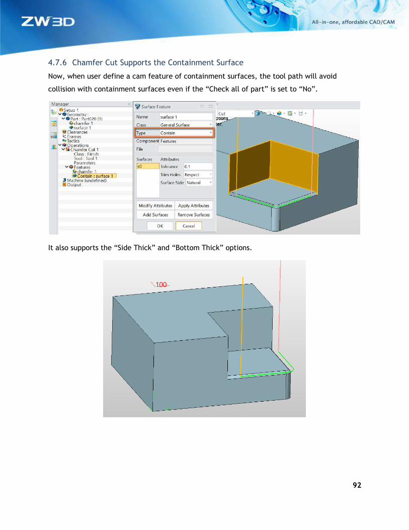
92
4.7.6 Chamfer Cut Supports the Containment Surface
Now, when user define a cam feature of containment surfaces, the tool path will avoid
collision with containment surfaces even if the “Check all of part” is set to “No”.
It also supports the “Side Thick” and “Bottom Thick” options.