zw3d cad/cam excise
TRANSCRIPT


Contents 1.1 General Process of Drawing Sketch ................................................................................................................ 1
1.2 Sketch Exercise Cases ..................................................................................................................................... 2
2.1 General Process of Solid Modeling ................................................................................................................. 8
2.2 Solid-Surface Hybrid Modeling....................................................................................................................... 8
2.3 Solid Modeling Exercise Cases ....................................................................................................................... 9
3.1 General Process of Surface Modeling ........................................................................................................... 18
3.2 Solid-Surface Hybrid Modeling..................................................................................................................... 18
3.3 Surface Modeling Exercise Cases .................................................................................................................. 19
4.1 General Process of Bottom-up Design ........................................................................................................... 24
4.2 General Process of Top-down Design ............................................................................................................ 24
4.3 Assembly Design Exercise Cases .................................................................................................................. 25
5.1 Overview of 2D Drawing .............................................................................................................................. 30
5.2 2D Drawing Exercise Cases .......................................................................................................................... 31
6.1 Brief Introduction of ZW3D Mold ................................................................................................................ 36
6.2 General Process of Mold Design ................................................................................................................... 36
6.3 Mold Design Exercise Cases ......................................................................................................................... 37
7.1 2X Turning Introduction ................................................................................................................................ 43
7.2 General Process of 2X Turning ...................................................................................................................... 43
7.3 2X Turning Exercise Cases ............................................................................................................................ 44
8.1 2X Milling Introduction ................................................................................................................................. 48
8.2 General Process of 2X Milling ...................................................................................................................... 48
8.3 2X Milling Exercise Cases ............................................................................................................................ 49
9.1 3X Milling Introduction ................................................................................................................................. 54
9.2 General Process of 3X Milling ...................................................................................................................... 54
9.3 3X Milling Exercise Cases ............................................................................................................................ 55
10.1 4-5X Milling Introduction ............................................................................................................................. 60
10.2 General Process of 4-5X Milling ................................................................................................................... 60
10.3 4-5X Milling Exercise Cases ......................................................................................................................... 61
1
2D Sketch
1.1 General Process of Drawing Sketch
1) Draw some necessary construction geometry with constraints or dimensions.
2) Draw the outline of the sketch with the drawing features(such as: quick draw, line, circle, arc)
3) Add the constraints, such as: tangent, equal length…
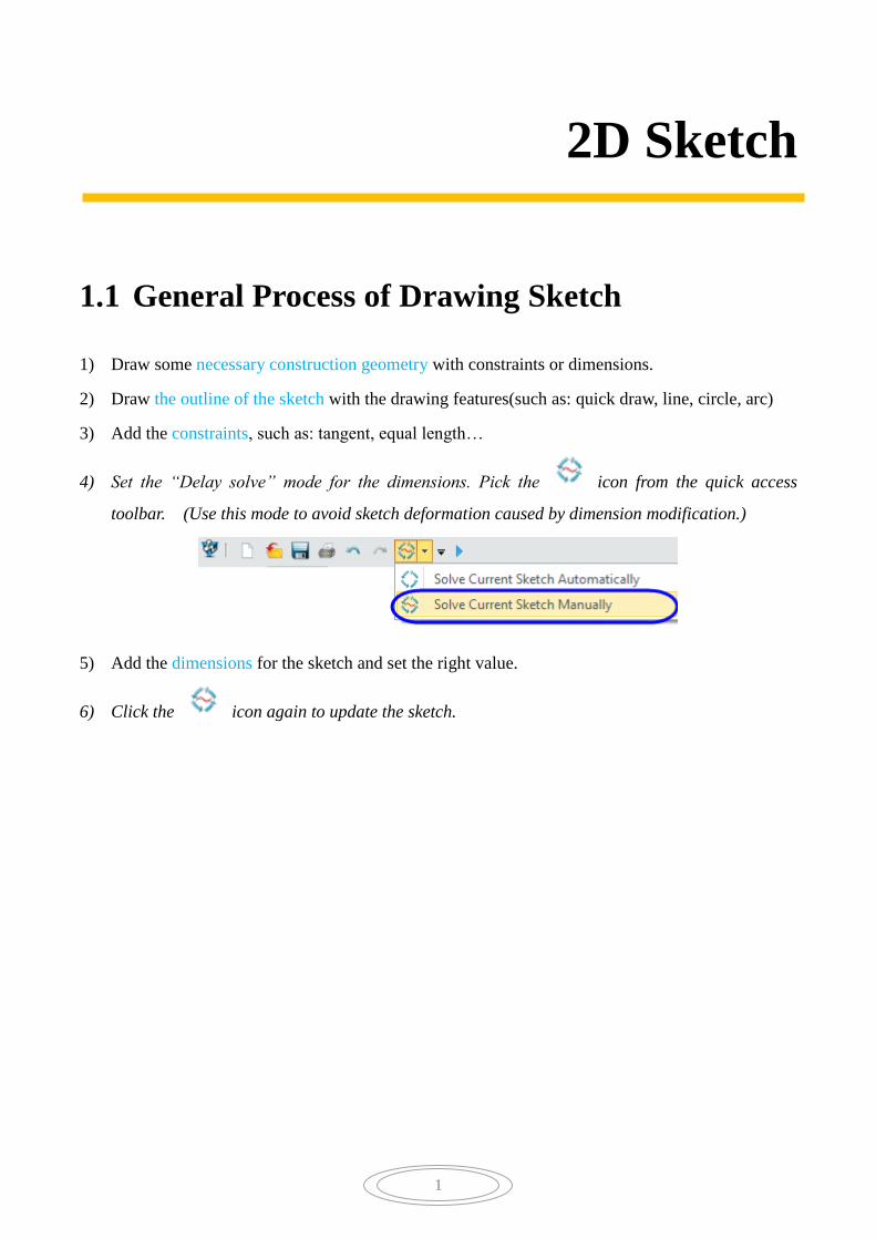
4) Set the “Delay solve” mode for the dimensions. Pick the icon from the quick access
toolbar. (Use this mode to avoid sketch deformation caused by dimension modification.)
5) Add the dimensions for the sketch and set the right value.
6) Click the icon again to update the sketch.

Sketch Design 01
2
1.2 Sketch Exercise Cases
Notes: 1. Recommended commands: Quick Draw and Quick Dimension .
Notes: 1.Recommended commands: Circle, Quick Draw, Mirror and OneTouch Trim
Case 1
Case 2

Sketch Design 01
3
Notes: 1. How to create construction geometry?
2. Recommended commands: Circle, Rectangle, Fillet Chain and Power Trim .
Notes: 1. Recommended commands: Circle, Fillet , Pattern and Power Trim.
Case 3
Case 4

Sketch Design 01
4
Notes: 1. Recommended commands: Slot and Fillet.
Notes: 1. Recommended commands: Line, Circle and Arc.
2. When drawing the arc, set the snap method to “Tangent”.
Case 5
Case 6

Sketch Design 01
5
Notes: 1. Recommended commands: Equation curve
Notes: 1.How to quickly draw this sketch?
Case 8
Case 7

Sketch Design 01
6
Notes: 1. Recommended commands: Arc and Mirror .
2. When drawing the arc, set the snap method as “Tangent”.
Case 9
Sketch Design 01
7
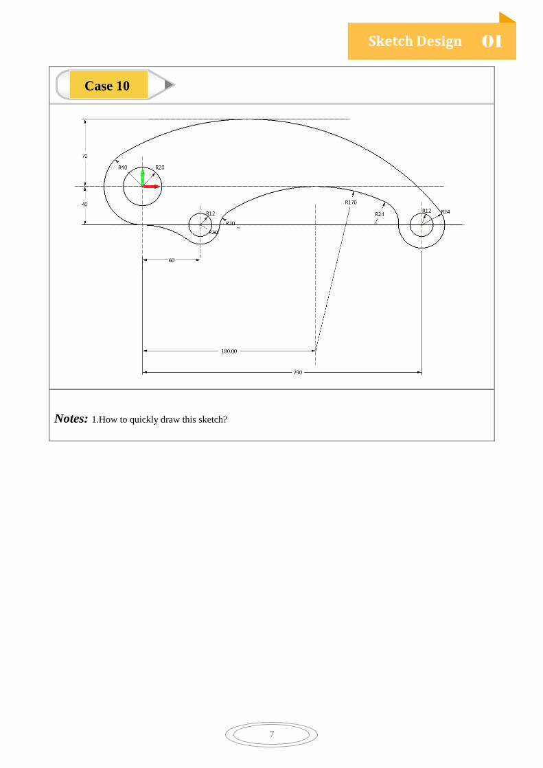
Notes: 1.How to quickly draw this sketch?
Case 10

8
Solid Modeling
2.1 General Process of Solid Modeling
1) Draw some datum for locating the sketch or 3D wireframes.
2) Draw the sketches with the dimension and constraints.
3) Make the solid part, such as: Extrude, Revolve, Fillet, Hole, Rib…
4) Edit the geometry, such as: Boolean, Trim, Mirror, Pattern…
5) More detail design
2.2 Solid-Surface Hybrid Modeling
ZW3D has unique Solid-Surface Hybrid Modeling technology breaks down the boundaries between
solid and surface features. Designers can directly make a Boolean operation for surface and solid
geometries.

Solid Modeling 02
9
2.3 Solid Modeling Exercise Cases
Notes: 1. Recommended commands: Variable, Sketch, Extrude, Revolve and Hole.
2. What’s the volume of this 3D model?
Case 1

Solid Modeling 02
10
Step1: 3D curve
Step 2: Solid model
Notes: 1. Recommended commands: Polyline, Fillet, and Sweep Rod.
2.Turn on”Smart Point Ref” to draw the polyline.
Case 2

Solid Modeling 02
11
Notes: 1. Recommended commands: Sketch, Extrude, Fillet and Hole.
Case 3

Solid Modeling 02
12
Notes: 1. Recommended commands: Sketch and Loft .
Case 4

Solid Modeling 02
13
Step1: Main shape of impeller
Step 2: Design impeller blade (Number is 12; Thickness is 1.5 mm.)
Notes: 1. Recommended commands: Sketch, Extrude, Revolve, Pattern, Chamfer and Fillet.
Case 5

Solid Modeling 02
14
Notes: 1. Recommended commands: Sketch, Extrude, Revolve, Swept Rod, Shell, and Combination.
Case 6

Solid Modeling 02
15
Notes: 1. Recommended commands: Sketch, Spiral Helix curve, Sweep Rod, Fillet, Datum plane, Blend
curve, Through point curve.
Case 7

Solid Modeling 02
16
Notes: 1. Recommended commands: Revolve, Wrap to Faces, and Pattern (Number = 20).
2. Try different method to design this case.
Case 8

Solid Modeling 02
17
Notes: 1. How to design the 3D curve?
2. Recommended commands: Sketch, Extrude, InterX Curve, Rod, Trim, Shell, Combine.
Case 9

18
Surface Modeling
3.1 General Process of Surface Modeling
1) Draw sketch curves
2) Create 3D curves by wireframe tools, such as: Through Point Curve, Project to Face …
3) With shape and freeform function to create solid or surface geometry
4) Sew the surfaces together or combine the solids and surfaces to get the final surface model
3.2 Solid-Surface Hybrid Modeling
ZW3D has unique Solid-Surface Hybrid Modeling technology breaks down the boundaries between
solid and surface features. Designers can directly do Boolean operation on the surface geometry with
the solid geometry.

Surface Modeling
03
19
3.3 Surface Modeling Exercise Cases
Notes: 1. Recommended commands: Sketch, Project to Face, Curve Mesh, Blend Face, Combine, & Fillet.
Case 1

Surface Modeling
03
20
Notes: 1. Recommended commands: Sketch, Project, Combined Projection, Curve Mesh, FEM Patch,
Revolve, Sew, Fillet .etc
Case 2

Surface Modeling
03
21
Notes: 1. Recommended commands: Curve mesh, FEM patch, Shell, Patten, Thread Hole, Fillet .
Case 3

Surface Modeling
03
22
Notes: 1. Recommended commands: Sketch, Drive Curve Loft, Combine, Revolve, Fillet and Shell.
Case 4
Surface Modeling
03
23
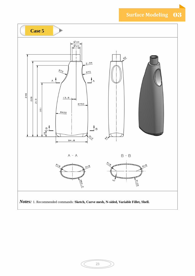
Notes: 1. Recommended commands: Sketch, Curve mesh, N-sided, Variable Fillet, Shell.
Case 5

24
Assembly Design
4.1 General Process of Bottom-up Design
1) Design the individual parts with modeling functions
2) Put the component together to develop the top-level assembly:
Insert the component -> Add the alignment
3) Use “Drag” tool to check the movement of the components with defined constraints
4) With “Interference Check” function to check whether there is interference between components
5) Create the animation to simulate the movement/ assembly process/ disassembly process
4.2 General Process of Top-down Design
1) Draw skeleton model, such as outline feature and control surface
2) Draw the associative parts refer to the skeleton model (How to apply the associative copy?)
3) Add the needed constraints to the components to define the final assembly
4) Other processes are the same with the Bottom-up design
Top-level Assembly
Components design Components design Components design
Skeleton Modeling
Components design Components design Components design

Assembly Design
04
25
4.3 Assembly Design Exercise Cases
Notes: 1. Assembly the components with well defined constraints.
2. There are two different Footboard part. Try to learn how to add /activate/delete the alternate.
3. With part configuration function to define two diffenet configuration in wheel part(as shown above).
4. Define the suitable angle constaint, then record different assembly configuration.
5. Make an exploded view.
6. Recommended commands: Insert Component, Alignment, Add / Activate / Delete Alternate,
Record/Activate configuration, Create config ( In history manager, click any blank area to get
right menu.), Exploded view.
Case 1

Assembly Design
04
26
Notes: 1.With the plates and gears to make gear assembly.
2. Recommended command: Gear Alignment
Case 2

Assembly Design
04
27
Notes: 1. Make an assembly with well define constraints.
2. Components status: Plate is fixed; Leg is well defined. Other components both has a certain degree
of freedom.Limited rang of movement of components as shown above.
Case 3

Assembly Design
04
28
Notes: 1.Please refer to the skeleton model and reference model to do top-down assembly design.
2. Recommended command: Reference -> Associative copy
3. The thickness of parts is 2 mm.
Case 4

Assembly Design
04
29
Notes: 1.Make an assembly with well defined constraints. (It means that the product can show the correct
movement. If you drag some components, the above stations are abaliable.)
2. Create two animations:
one is product movement animation; one is disassembly and assembly process animation.
Case 5

30
2D Drawing
5.1 Overview of 2D Drawing
Design the 3D model in ZW3D, and then create the 2D drawing. The associated relationship exists
between them. If the 3D model is changed, the 2D drawing can auto-update.
General, the 2D drawing of a part consists of three parts:
1 Standards view (Top, Front, Right, Left, Bottom, Back and Isometric view),
Projection view, Section view, Detail view and so on.
2 Dimension (Shape dimension & Position dimension), Tolerance (Dimension tolerances,
Form tolerances & Position tolerances), Datum symbol, Surface finish symbol and text
Annotation.
3 Sheet format: Sheet border, Title block and so on.
2D drawing of an assembly includes many different views, assembly dimension, fit dimension, BOM
table and so on.

2D Drawing
05
31
5.2 2D Drawing Exercise Cases
Notes: 1.Views: Standard view, Projection view, Full section view and Isometric view.
2. Dimension attribute customization
3. Center line, and text
4. This part is case3 of surface modeling.
Case 1

2D Drawing
05
32
Notes: 1. Views: Standard view, Broken section view, Section views
2. Recommended commands: DimTools
Label, Feature control, Datum feature,Center line, Surface finish symbol.
3. With style manager to define the dimension style before adding dimensions.
4. Manually create the hole dimensions by label command.
Case 2
2D Drawing
05
33
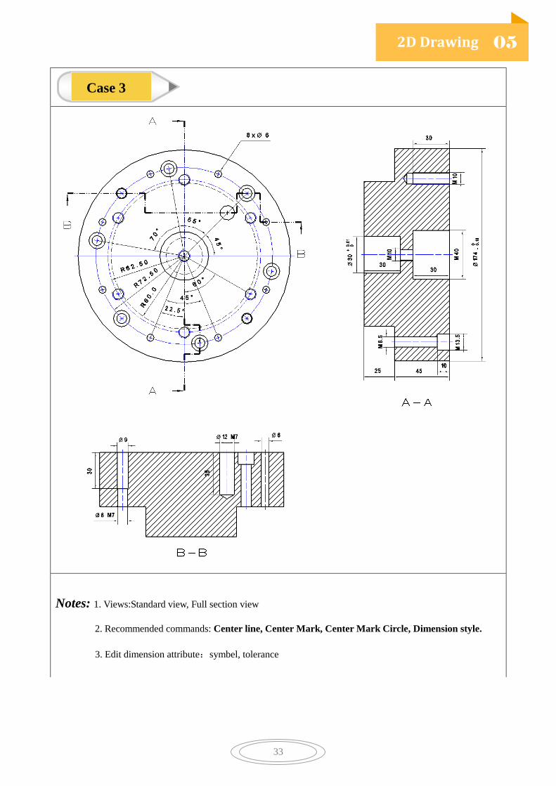
Notes: 1. Views:Standard view, Full section view
2. Recommended commands: Center line, Center Mark, Center Mark Circle, Dimension style.
3. Edit dimension attribute:symbel, tolerance
Case 3

2D Drawing
05
34
Notes: 1. Views:Standard view, Projection view, Aligned section view,Auxilary view
2. Recommended commands: Rotate view
3. This part is case3 of solid modeling.
Case 4

2D Drawing
05
35
Title block:
Notes: 1.2D Drawing template is A2_H (ISO).
2.Title block should include this information: part name, part number, part material, part mass,
designer, manager, date.
Case 5

36
Mold Design
6.1 Brief Introduction of ZW3D Mold
Solid model is not a requirement for splitting since ZW3D unique Solid-Surface hybrid modeling
technology. It can help designer save much more time in healing model. If a perfect product model is
needed, designer can use the healing tools or freeform tools to healing the model.
ZW3D provides two splitting methods: Parting lines and Face region definition. It gives the designer
the flexibility to choose the suitable way according to real cases.
6.2 General Process of Mold Design
1) Import the product model
2) Make the preparation work: Healing the model, Check the draft / thickness, Adjust the position…
3) Split the product into core and cavity
4) Create hole patch surfaces and outside parting faces
5) Trim the mold plate to core and cavity plate
6) Add the Mold Base and some standard parts
7) Do other structural design, including Electrode, Slider, Insert, Lifer, Cooling system…
Mold Design
06
37
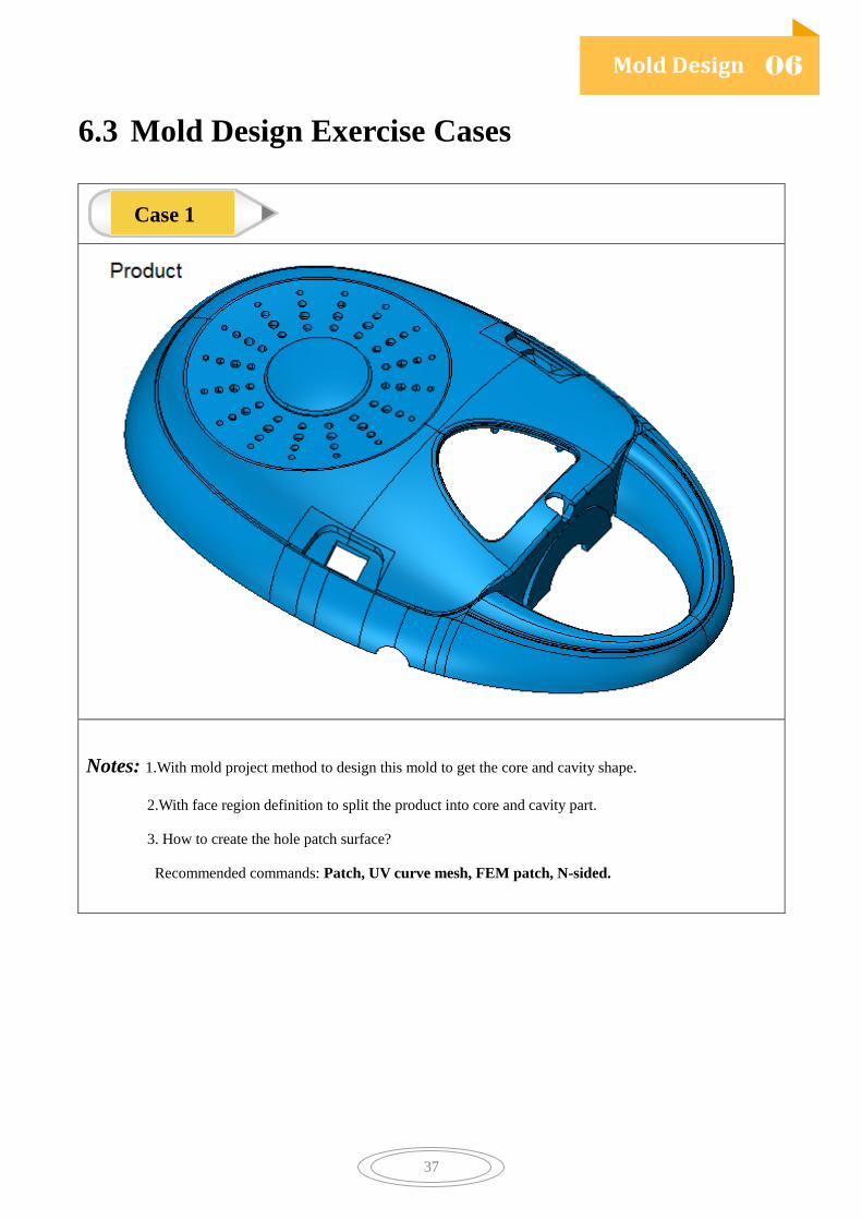
6.3 Mold Design Exercise Cases
Notes: 1.With mold project method to design this mold to get the core and cavity shape.
2.With face region definition to split the product into core and cavity part.
3. How to create the hole patch surface?
Recommended commands: Patch, UV curve mesh, FEM patch, N-sided.
Case 1
Mold Design
06
38
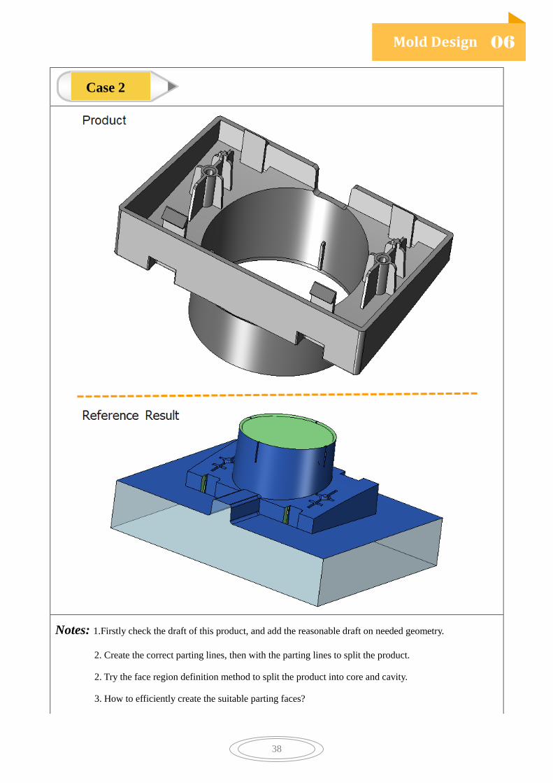
Notes: 1.Firstly check the draft of this product, and add the reasonable draft on needed geometry.
2. Create the correct parting lines, then with the parting lines to split the product.
2. Try the face region definition method to split the product into core and cavity.
3. How to efficiently create the suitable parting faces?
Case 2
Mold Design
06
39
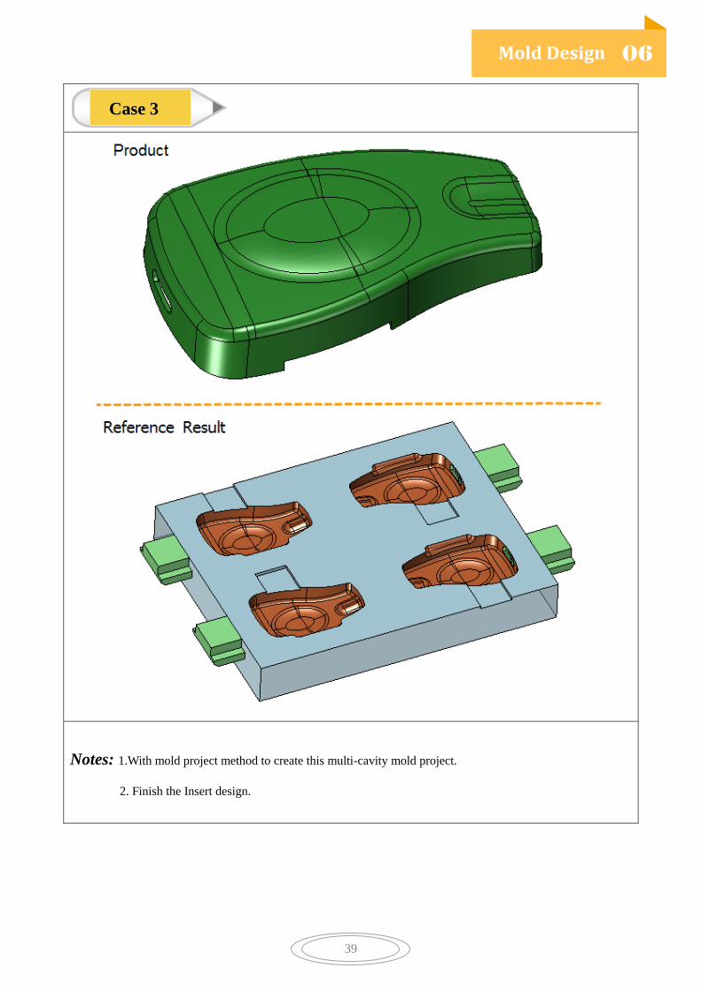
Notes: 1.With mold project method to create this multi-cavity mold project.
2. Finish the Insert design.
Case 3

Mold Design
06
40
Notes: 1. With mold project method to create this multi-product case.
2. Create reasonable hole patch surface.
Case 4

Mold Design
06
41
Notes: 1.With healing tools or freeform tools to heal this product model.
2.Finish the Insert, Lift , Slider and Inject Pin design.
3.Add the Mold base and some standard part, such as: Screw, LocateRing.
Case 5

Mold Design
06
42
Notes: 1.How to deal with the cross face during the core and cavity region difination?
2. Recommended commands: Split Face, Region, Patch.
Case 6

43
2X Turning
7.1 2X Turning Introduction
ZW3D 2X Turning provides quick and easy operations for all types of turned part. It supports OD
and ID Roughing, Finishing, Grooving, Threading, and Facing, Drilling, Part-off features. Based on
the 2D wireframe and 3D part, user can easily generate and verify the tool path.
7.2 General Process of 2X Turning
1) Create new CAM plan and import geometry.
2) Define Turning profile, set the profile type to Part and make sure the direction is
Counter-clockwise.
3) Create Turning operations, such as facing, roughing, finishing, etc.
4) After creating tool path, verify and solid verify the tool path to check if there is any problem.
5) Define the Machine, and choose a proper post configure.
6) Create output NC code and operation list.

2X Turning
07
44
7.3 2X Turning Exercise Cases
Notes: 1. Recommended commands: Facing, Drilling, Rough, Finish, Groove, Threads, Part-off;
2.Define Profile Feature, Set Profile Type and Direction;
3. Define Parameters: OD turning, ID turning, Cutting Direction, etc;
4. Verify and Solid Verify the Tool Path;
5.Define Machine, select ZW_Fanuc_Turning as the post configure and create Output;
6.Output NC Code, Operation List;
Case 1

2X Turning
07
45
Notes: 1. Recommended Commands: Facing, Rough, Groove Turning, Drilling, Finishing Turning, Part-Off;
2. Create Sketch, Define Profile Feature, Set the Right Profile Type and Direction.
3.Define Tool, OD Turning and ID Turning Tool;
4.Define Parameter: Boundary, Into Concave, Station Point;
5.Define Machine, Choose Post Configure and Output NC Code
Case 2

2X Turning
07
46
Notes: 1. Recommanded Commands:Facing, Rough, Finish, Groove, Drilling, Part-Off.
2. Create CAM Plan with Sketch file;
3.Define Profile Feature with right Profile type and Direction;
4.Define Parameter: Boundary, Station Pint, Into Concave, Cutting Direction.
5. Verify, Solid Verify;
6. Define machine,Select Post Configure and Output NC code.
Case 3

2X Turning
07
47
Notes: 1. Recommended Commands: Facing, Rough, Groove, Drill, Part-Off.
2. Insert Component, Define Component Type.
3. Define Parameter: Boundary, Part-off Corner, Station Point.
4. Solid Verify the Tool Path, Analysis the Rest Material.
Case 4
48
2X Milling
8.1 2X Milling Introduction
With ZW3D 2X milling, programmers can easily and quickly get tool-path based on 2D drawing or
3D model. Also ZW3D 2X milling provide automatic feature recognition, tool compensation,
reference operation and draft control for the user to generate ideal tool path. The vivid verify/solid
verify technology easily shows the machining process and rest material. The build-in post configure
can meet all kinds of machine demands.
8.2 General Process of 2X Milling
1) Create new CAM plan and import geometry.
2) Define 2X milling feature, and profile feature is recommended in 2X milling.
3) Create 2X milling Operations, such as Top facing, Spiral, Zigzag, Profile, etc. Select cutting tools
for each operation, and define proper parameter, speed and feed.
4) After creating tool path, verify and solid verify the tool path to check if there is any problem.
5) Define the Machine, and choose a proper post configure.
6) Create output NC code and operation list.

2X Milling
08
49
8.3 2X Milling Exercise Cases
Notes: 1. Recommended Commands:Top-facing, Zigzag, Spiral, Profile, Hole tactic, Ramp;
2.Define different Feature, Hole &Profile;
3.Define Parameter: Boundary, Lead in and out, Speed and Feed, etc;
4.Create Hole tactic, Define tactic feature;
5.Verify or Solid verify the Tool Path;
6.Output NC Code and Operation List.
Case 1

2X Milling
08
50
Notes: 1.Recommended Commands: Zigzag, Profile, Spiral, 2X milling Tactic, Drill.
2.Define Features, Hole and Profile.
3.Define Parameter: Lead in and out, Boundary, Speed and Feed, etc.
4.Create Frame and Select frame in Parameter.
5.Verify and solid verify the Tool Path.
6.Define Machine, Select Post Configure and Output NC code.
Case 2

2X Milling
08
51
Notes: 1.Recommended Commands:Top facing, Hole tactic, Spiral, Ramp, Drill, Profile ;
2. Define Feature: Profile(including multiply loop), Hole, etc;
3. Define Prameter: Stepdown, Side Thick, Bottom Thick, Cut Order, Edit Tactic,etc;
4. Verify and solid verify.
Case 3

2X Milling
08
52
Notes: 1.Recommended Command:Center, Drill, Peck, Chip, Ream, Bore, Fine Bore, Counter Bore,
Counter Sink, Tap;
2.Define Hole Features.
3.Define Operation Parameter: Cutting Depth, Cut Order,etc.
4.Verify Tool Path.
5.Try to create the correct tool path with hole tactic.
Case 4

2X Milling
08
53
Notes: 1.Recommended Command: Profile, Charmfer Cut, Corner Round, Helical,etc.
2.Define Feature: Charmfer, Corner Round, Profile;
3.Create Frame, Use new Frame in Parameter.
4. Create Folder and Insert Operation.
5.Verify and Solid Verify the Tool Path.
Case 5

54
3X Milling
9.1 3X Milling Introduction
With ZW3D 3X milling (Quick Mill), programmers can easily and quickly get tool-path based on 2D
drawing or 3D model. The vivid verify/solid verify technology easily shows the machining process
and rest material. The build-in post configure can meet all kinds of machine demands. Advantages of
Quick Mill are listed below.
Support High Speed Milling
High quality of finishing surface
Improve productivity with efficient roughing
Reduce programming and machining time by 30~50%
Lengthen tool life by 50%, save tool cost
9.2 General Process of 3X Milling
1) Create new CAM plan and import geometry.
2) Define 3X milling feature for each operation, in order to avoid gouge. Part feature is
recommended to use in each operation of 3X milling.
3) Create 3X milling operations. Firstly create rough milling operations, like offset2D, smooth flow,
etc, and then create finishing operation like Z level, lace, HSM lace, etc. Select cutting tools for
each operation, and define proper parameter, speed and feed.
4) After finished create tool path, verify and solid verify the tool path to check if there is any
problem.
5) Define the Machine, and choose a proper post configure.
6) Create output NC code and operation list.

3X Milling
09
55
9.3 3X Milling Exercise Cases
Notes: 1.Recommended Command:Top face cut, offset 2D, Z level, Lace, Offset 3D.
2.Define Feature(Recommended feature: Profile feature);
3.Create Tool Library file, and when define tool, use the tools in Tool Library file;
4.Define Reference Milling for semi-Rough milling.
5.Trim the tool path with tool path editor.
6. Define proper parameter, such as boundarry, Filer, Link and Lead, etc.
Case 1

3X Milling
09
56
Notes: 1.Recommended Command:Top face cut, offset 2D, Z level, HSM Offset 2D, HSM Lace.
2.Change different Display mode ;
3.Define Reference Milling for Semi-Roughing Milling.
4. Define proper parameter, such as Boundarry, Filter, Link and Lead, etc.
5. Verify and Solid Verify the tool path.
Case 2

3X Milling
09
57
Notes: 1.Recommended Command:Rough Smooth Flow, Offset 2D, Angle Limiting, Pencil Cut.
2.Define Feature(Recommended feature: Profile feature);
3.Compare the difference between Smoth Flow and Offset 2D.
4. Define proper parameter ,sucha s Boundarry, Filter, Link and Lead, etc.
5. Verify and Solid verify the tool path.
Case 3

3X Milling
09
58
Notes: 1.Recommended Command:Top Facing, Profile Cut, Rough Offset 2D, Lace, Offset 3D.
2.Define Feature(Recommended method: Profile feature) ;
3.Use Reference finishing operation
4. Define proper parameter , such as boundarry, Filter, Link and Lead, etc.
5. Verify and Solid verify the tool path.
6.Set Material, Define Machine, Output NC and Operation List
Case 4

3X Milling
09
59
Notes: 1.Recommended Command: Smooth Flow, Offset 2D, Offset lace, Z level, Pencil cut, Engrave 2D,
HSM Flow.
2.Define machining Feature (Recommended method: Profile feature) ;
3.Compare the differnence between Smooth Flow, Offset 2D and Offset lace;
4. Define proper parameter, such as Boundarry, Filter, Link and Lead, etc.
5. Verify and Solid verify the tool path.
6.Set Material, Output NC and Operation List
Case 5

60
4-5X Milling
10.1 4-5X Milling Introduction
ZW3D 4-5X milling provides a good solution for multi-axis machining with high machining
precision and efficiency and high. With verify and solid verify, it provide more safety tool path.
Expand your machining capability in deep cavity, reducing the number of electrodes. Intelligent
tool-path link make your programming easier.
10.2 General Process of 4-5X Milling
1) Create new CAM plan and import geometry.
2) Define 5X milling feature for each operations, in order to avoid gouge, part feature is
recommended to use in each operation of 5X milling.
3) Create 5X milling Operations. Insert the feature and define proper parameter.
4) After finished create tool path, verify and solid verify the tool path to check if there is any
problem.
5) Define the Machine, and choose a proper post configure.
6) Create output NC code and operation list.
4-5X Milling
10
61
10.3 4-5X Milling Exercise Cases
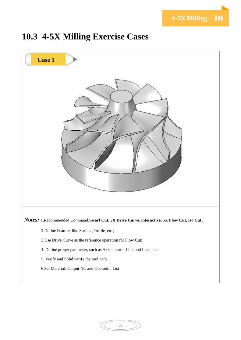
Notes: 1.Recommended Command:Swarf Cut, 5X Drive Curve, interactive, 5X Flow Cut, Iso Cut;
2.Define Feature, like Surface,Profile, etc ;
3.Use Drive Curve as the reference operation for Flow Cut;
4. Define proper parameter, such as Axis control, Link and Lead, etc.
5. Verify and Solid verify the tool path.
6.Set Material, Output NC and Operation List
Case 1

4-5X Milling
10
62
Notes: 1.Recommended Command: Swarf Cut, 5X Drive Curve, Plane;
2.Define Feature, like Surface,Profile, etc ;
3.Compare the difference between 5 axis control and 4 axis control;
4. Define proper parameter, such as Axis control, Link and Lead, etc.
5. Verify and Solid verify the tool path.
6.Set Material, Output NC and Operation List.
Case 2

4-5X Milling
10
63
Notes: 1.Recommended Command: Side Cut;
2. Define proper parameter, Axis control.
3. Verify and Solid verify the tool path.
4.Set Material, Output NC and Operation List.
Case 3

4-5X Milling
10
64
http://www.zwsoft.com/zw3d/