yia single-effect absorption chillers steam and hot … single-effect absorption chillers steam and...
TRANSCRIPT

FORM 155.16-EG1 (1008)
YIA Single-Effect Absorption Chillers Steam And Hot Water ChillersStyle A
120-1377 TONS(420 - 4840 kW)

2 JOHNSON CONTROLS
FORM 155.16-EG1 (1008) ..................................................................................................................................................................................... 1Nomenclature........................................................................................................................................................................................................ 3Introduction ........................................................................................................................................................................................................... 4Reliability Features............................................................................................................................................................................................... 5How It Works ......................................................................................................................................................................................................... 8MicroComputer Control Center ......................................................................................................................................................................... 10Mechanical Specifications ................................................................................................................................................................................. 12Optional Features ............................................................................................................................................................................................... 15Application Data ................................................................................................................................................................................................. 16Ratings ................................................................................................................................................................................................................ 30Nozzle Arrangements ......................................................................................................................................................................................... 34Physical Data ...................................................................................................................................................................................................... 36Electrical Data ..................................................................................................................................................................................................... 39Guide Specifications .......................................................................................................................................................................................... 41
Table of Contents

3
FORM 155.16-EG1 (1008)
JOHNSON CONTROLS
NOMENCLATURE
The model number denotes the following characteristics of the unit:
MODIFICATION LEVEL
MODEL
HEAT SOURCE ST = Steam HW = Hot Water
SIZE CODE
SPECIAL Special Tubes Contract Job
ELECTRICAL CODE 17 = 208-3-60 28 = 230-3-60 46 = 460-3-60 50 = 380/400-3-50 58 = 575-3-60
YIA ST 8E1 46 A S
Nomenclature

4 JOHNSON CONTROLS
Introduction
COGENERATION
INLET AIR COOLING PEAK SHAVING/COMMERCIAL COOLING
WASTE HEAT RECOVERY
Today’s environmental and energy considerations demand innovative chiller plant designs which save expensive peak load kW-hours and eliminate CFC’s. In a growing number of applications with waste heat or abundant low pressure steam, single effect absorption chillers offer an ideal means of saving on cooling costs without a significant installation cost penalty.
That’s why Johnson Controls is proud to introduce the YIA Single Effect Absorption Chiller. The YIA Absorption Chiller offers the rugged, industrial-grade design of our previous single effect model, with a whole new package of user-friendly microprocessor controls, designed to increase reliability and enhance performance.
Applications particularly well-suited for the YORK YIA Absorption Chiller include the following:
Cogeneration – For cogeneration systems, high pres-sure steam has many valuable uses, while low pressure steam is considerably less useful, yet more plentiful. In these plants, the YIA absorber can provide cooling with low pressure steam or hot water, freeing high pressure steam for power generation or other valuable uses.
Inlet Air Cooling – Use a YIA chiller to cool inlet air to a gas turbine or a compressor. The lower specific volume associated with cooler air provides more combustion ca-pacity by increasing the overall efficiency of the system.
Waste Heat Recovery – Recover waste heat from printing plants, incinerators or gas engine jacket water to provide required comfort or process cooling at little operational cost.
Commercial Cooling/Peak Shaving – For particularly pronounced peak loads with few operating hours, the YIA absorber’s lower first cost may provide an acceptable payback when more efficient, yet more expensive double effect chillers cannot.
For these and similar money-saving designs, consider the field-proven YIA design. In over thirty-five years of opera-tion, the YORK single-effect design has proven itself in applications ranging from schools to refineries. Now, with state-of-the-art controls and continual product improve-ment, the YORK YIA machine is truly without peer. When it comes to absorption technology, there’s only one leader - Johnson Controls
TURBINE

5
FORM 155.16-EG1 (1008)
JOHNSON CONTROLS
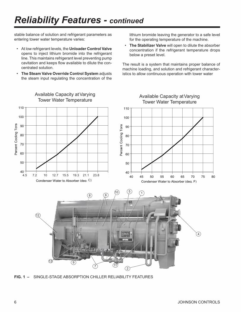
Reliability FeaturesThe YORK YIA Absorption Chiller introduces a revolu-tionary system of unit controls and mechanical devices designed to keep the chiller running in even the most extreme circumstances. Old concerns about crystallization are approached with a hybrid of new technology and older, proven methods. Additionally, the YIA chiller contains a host of other features designed to give the machine a long, trouble-free life. The result: the smartest, safest, and most reliable single effect absorption chiller on the market today. See Fig. 1 for the location of the reliability features.
1. Concentration Limit – The MicroComputerControl Center actually detects high lithium bromide concentra-tions which can damage the unit. When high concentra-tions are present, the panel limits heat input until the solution reaches equilibrium at a lower concentration. In this manner, the machine operates only within the safe and practical limits of the lithium bromide absorption cycle.
2. “J” Tube – If crystallization were to occur, it would begin in the strong solution side of the solution heat ex-changer. This would force the strong solution to back up into the generator. At a certain generator solution level, the hot strong solution would over flow into the “J” tube. This tube sends hot solution directly to the absorber, im-mediately warming the weak solution. The heated weak solution would then warm the crystallized solution on the opposite side of the heat exchanger. This transfer of heat will cause the crystallized lithium bromide to move back into solution, allowing the unit to continue operation.
3. Stabilizer Valve – If minor crystallization occurs and causes overflow in the “J” tube, the temperature of the “J” tube will increase because of the hot solution. A specially placed sensor detects this change in temperature, and the panel sends a signal to open a solenoid on the unit’s pat-ented Stabilizer Valve. When the Stabilizer Valve is open, refrigerant water is injected into the strong solution im-mediately before the heat exchanger. The water serves to dilute the strong solution, allowing the crystallized lithium bromide to become soluble at a lower concentration.
4. Steam Supply Pressure/Temperature Limit – The Control Center actually monitors the inlet steam (or hot water) temperature and steam pressure. The panel will close the control valve to the machine if temperatures or pressures become excessive, thus protecting the machine from potentially harmful conditions.
5. Load Inhibition – Before the YIA unit shuts down due to a given safety condition (see Controls section for a complete list), it first crosses a warning threshold which will cause the panel to limit heat input to the machine. In this manner, the YIA unit continues its vital task of mak-ing chilled water, while allowing operators the opportunity to find system deficiencies before they lead to an actual shutdown.
6. Stainless Steel Pans – Both the pan in the evaporator (which holds refrigerant) and the pan in the condenser (which holds refrigerant) are fabricated from stainless steel, giving the machine added protection against cor-rosion.
7. Hermetic Pumps – The YIA’s industrial pump pro-vides a life of trouble-free operation with a recommended 55,000 hours between service inspections. These pumps feature self-adjusting spring loaded conical bearings that ensure concentric rotation and reduce interference. These bearings, made of carbon graphite, maintain cor-rect bearing/journal fit at all times and ensure extended trouble free operation.
8. Double Walled Evaporator – The Evaporator on each YIA model is lined with a second wall, reducing the amount of sweating that occurs on the evaporator shell. To eliminate sweating on the evaporator shell and refrigerant piping, the refrigerant insulation option must be applied.
9. Purge System – YORK’s efficient purge system ex-pels non-condensable gases from the unit’s external purge chamber without the risk of spilling lithium bromide.
10. Evaporator Spray Nozzles – Evaporator spray nozzles are made of corrosion resistant brass to ensure long life.
11. Absorber Spray Nozzles – Absorber spray nozzles are fabricated from stainless steel or brass, providing trouble-free operation in a particularly demanding envi-ronment.
12. Single Power Connection – A single point power connection is all that is required for the YIA Absorption Chiller, providing further reliability and ease of installa-tion.
13. 45°F (7.2°C) Condenser Water – The YIA chiller is capable of operating with entering condenser water temperatures as low as 45°F (7.2°C). Without proper compensation, lower tower water temperatures cause: low refrigerant level, potential for crystallization, and low refrigerant temperature. The combination of three control systems described below allow the YIA to maintain a
6 JOHNSON CONTROLS
Reliability Features - continued
12
8 6
2
4
117913
10 5 1
FIG. 1 – SINGLE-STAGE ABSORPTION CHILLER RELIABILITY FEATURES
stable balance of solution and refrigerant parameters as entering tower water temperature varies:
• At low refrigerant levels, the Unloader Control Valve opens to inject lithium bromide into the refrigerant line. This maintains refrigerant level preventing pump cavitation and keeps flow available to dilute the con-centrated solution.
• The Steam Valve Override Control System adjusts the steam input regulating the concentration of the
lithium bromide leaving the generator to a safe level for the operating temperature of the machine.
• The Stabilizer Valve will open to dilute the absorber concentration if the refrigerant temperature drops below a preset level.
The result is a system that maintains proper balance of machine loading, and solution and refrigerant character-istics to allow continuous operation with tower water
40
50
60
70
80
90
100
110
40 45 50 55 60 65 70 75 80Condenser Water to Absorber (deg. F)
Available C apacity atT ower Water
Available Capacity at VaryingTower Water Temperature
40
50
60
70
80
90
100
110
40 45 50 55 60 65 70 75 80Condenser Water to Absorber (deg. F)
Available C apacity atT ower Water
Available Capacity at VaryingTower Water Temperature
4.5 7.2 10 12.7 15.5 19.3 21.1 23.8 . C)

7
FORM 155.16-EG1 (1008)
JOHNSON CONTROLS
14. ADVAGuard™ 750 Corrosion Inhibitor – is an environmentally friendly inorganic corrosion inhibitor that provides superior corrosion protection. Corrosion inhibi-tors promote the formation of an oxide film on the surfaces of the chiller that are in contact with LiBr solution. ADVA-Guard™ 750 Corrosion Inhibitor creates a highly stable magnetite layer resulting in lower hydrogen generation
and only an eighth of the corrosion as compared with other traditional inhibitors.
15. Pump Isolation Valve – Refrigerant and Solution Pump suction and discharge connections equipped with factory installed isolation valves permit quick and easy servicing of pumps.
8 JOHNSON CONTROLS
How It Works
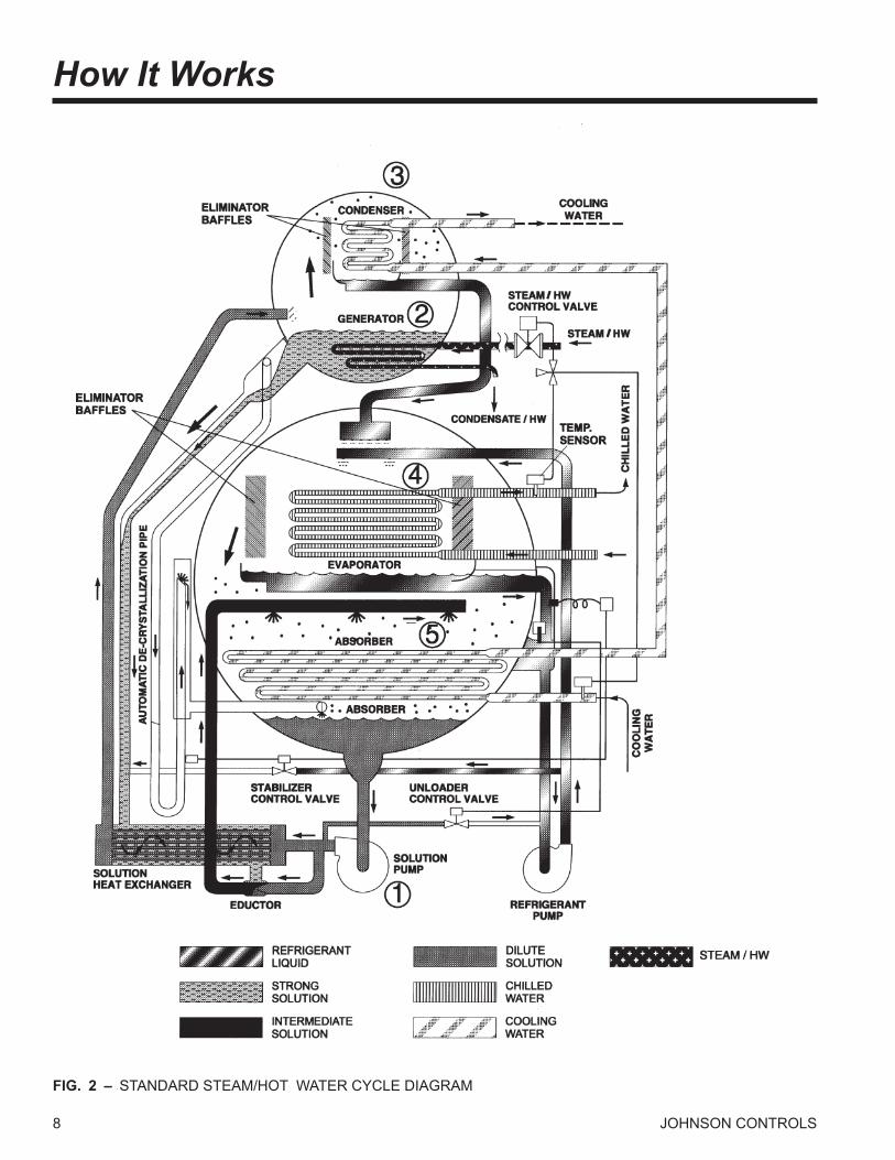
FIG. 2 – STANDARD STEAM/HOT WATER CYCLE DIAGRAM

9
FORM 155.16-EG1 (1008)
JOHNSON CONTROLS
in the lower shell and is sprayed over the evapora-tor tube bundle. Due to the extreme vacuum of the lower shell [6 mm Hg (0.8 kPa) absolute pressure], the refrigerant liquid boils at approximately 39°F (3.9°C), creating the refrigerant effect. (This vacuum is created by hygroscopic action - the strong affinity lithium bromide has for water - in the Absorber directly below.)
5. Absorber – As the refrigerant vapor migrates to the absorber from the evaporator, the strong lithium
bromide solution from the generator is sprayed over the top of the absorber tube bundle. The strong lithium bromide solution actually pulls the refrigerant vapor into solution, creating the extreme vacuum in the evaporator. The absorption of the refrigerant vapor into the lithium bromide solution also generates heat which is removed by the cooling water. The now dilute lithium bromide solution collects in the bottom of the lower shell, where it flows down to the solution pump. The chilling cycle is now completed and the process begins once again.
LD00904(R)
The single effect absorption cycle uses water as the re-frigerant and lithium bromide as the absorbent. It is the strong affinity that these two substances have for one another that makes the cycle work. The entire process occurs in almost a complete vacuum.
1. Solution Pump – A dilute lithium bromide solution is collected in the bottom of the absorber shell. From here, a hermetic solution pump moves the solution through a shell and tube heat exchanger for preheat-ing.
2. Generator – After exiting the heat exchanger, the dilute solution moves into the upper shell. The
solution surrounds a bundle of tubes which carries ei-ther steam or hot water. The steam or hot water transfers heat into the pool of dilute lithium bromide solution. The solution boils, sending refrigerant va-por upward into the condenser and leaving behind concentrated lithium bromide. The concentrated lithium bromide solution moves down to the heat exchanger, where it is cooled by the weak solution being pumped up to the generator.
3. Condenser – The refrigerant vapor migrates through
mist eliminators to the condenser tube bundle. The refrigerant vapor condenses on the tubes. The heat is removed by the cooling water which moves through the inside of the tubes. As the refrigerant condenses, it collects in a trough at the bottom of the condenser.
4. Evaporator – The refrigerant liquid moves from the condenser in the upper shell down to the evaporator
10 JOHNSON CONTROLS
MicroComputer Control Center
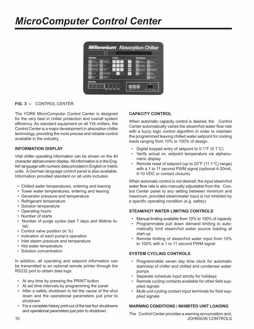
FIG. 3 – CONTROL CENTER
The YORK MicroComputer Control Center is designed for the very best in chiller protection and overall system efficiency. As standard equipment on all YIA chillers, the Control Center is a major development in absorption chiller technology, providing the most precise and reliable control available in the industry.
INFORMATION DISPLAY
Vital chiller operating information can be shown on the 40 character alphanumeric display. All information is in the Eng-lish language with numeric data provided in English or metric units. A German language control panel is also available. Information provided standard on all units includes:
• Chilled water temperatures, entering and leaving • Tower water temperatures, entering and leaving • Generator pressure and temperature • Refrigerant temperature • Solution temperature • Operating hours • Number of starts • Number of purge cycles (last 7 days and lifetime to-
tal) • Control valve position (in %) • Indication of each pump’s operation • Inlet steam pressure and temperature • Hot water temperature • Solution concentration
In addition, all operating and setpoint information can be transmitted to an optional remote printer through the RS232 port to obtain data logs: • At any time by pressing the PRINT button • At set time intervals by programming the panel • After a safety shutdown to list the cause of the shut
down and the operational parameters just prior to shutdown
• For a complete history print-out of the last four shutdowns and operational parameters just prior to shutdown.
CAPACITY CONTROL
When automatic capacity control is desired, the Control Center automatically varies the steam/hot water flow rate with a fuzzy logic control algorithm in order to maintain the programmed leaving chilled water setpoint for cooling loads ranging from 10% to 100% of design.
• Digital keypad entry of setpoint to 0.1°F (0.1°C) • Verify actual vs. setpoint temperature via alphanu-
meric display • Remote reset of setpoint (up to 20°F (11.1°C) range)
with a 1 to 11 second PWM signal (optional 4-20mA, 0-10 VDC or contact closure)
When automatic control is not desired, the input steam/hot water flow rate is also manually adjustable from the Con-trol Center panel to any setting between minimum and maximum, provided steam/water input is not inhibited by a specific operating condition (e.g. safety).
STEAM/HOT WATER LIMITING CONTROLS
• Manual limiting available from 10% to 100% of capacity • Programmable pull down demand limiting to auto-
matically limit steam/hot water source loading at start-up
• Remote limiting of steam/hot water input from 10% to 100% with a 1 to 11 second PWM signal
SYSTEM CYCLING CONTROLS
• Programmable seven day time clock for automatic start/stop of chiller and chilled and condenser water pumps
• Separate schedule input strictly for holidays • Remote cycling contacts available for other field sup-
plied signals • Multi-unit cycling contact input terminals for field sup-
plied signals
WARNING CONDITIONS / INHIBITED UNIT LOADING
The Control Center provides a warning annunciation and,
11
FORM 155.16-EG1 (1008)
JOHNSON CONTROLS
when beneficial to the machine, will limit heat input to 30% or 60% when operating conditions indicate the unit is mov-ing towards a safety shutdown. This gives the operator the opportunity to fix a problem before it leads to a complete safety shutdown. Warnings include the following:
• Low refrigerant temperature • High generator pressure • High entering condenser water temperature • Purge pump current overload • Faulty solution dilution temperature sensor • High inlet steam pressure • High inlet hot water temperature • High solution concentration
SHUTDOWN CONTROLS
The following conditions will lead to unit shutdown. After a shutdown, the reason for the shutdown is displayed in English on the alphanumeric display. Each annunciation details the day, time, reason for shutdown and the type of restart required.
Cycling – Those controls which automatically reset and permit auto restart of the system.
• Loss of condenser water flow • Low leaving chilled water temperature [2°F (1.1°C)
below setpoint] • Power failure (when automatic restart is selected)
Safety – Those controls which (when employed)require a manual operation to restart the system.
• Solution pump thermal or current overload • Refrigerant pump thermal or current overload • Low refrigerant temperature • Generator high temperature or pressure • Loss of chilled water flow • Power failure (when automatic restart not used) • High inlet steam temperature or pressure • High inlet hot water temperature • High solution concentration • Incomplete dilution cycle due to any of the following: • Power failure • Solution/refrigerant pump overloads
• Low refrigerant temperature • Loss of chilled water flow • Auxiliary safety shutdown terminals for field supplied
signals
CONTROL MODE SELECTION
The Control Center includes secure program and servic-ing capabilities. There are three keys for the selection of the control center modes:
• ACCESS CODE permits access to the control center PROGRAM button when the proper password is given
• Program permits operator to program the setpoints and select desired MODE: • LOCAL allows manual unit start and purging. • REMOTE allows remote start and stop of the
unit, remote reset of the chilled water tempera-ture and steam limit, while still allowing manual purging at the chiller
• SERVICE allows manual operation of the con-trol valve, including LOAD, UNLOAD, HOLD, and AUTO keys. Manual operation of all pumps is also included
ENERGY MANAGEMENT INTERFACE
By connecting with the YORK Integrated Systems Network, the Control Center can communicate all data accessible from the keypad (including all temperatures, pressures, alarms and operating data) to a remote DDC processor through a single shielded cable. In remote mode, the DDC processor may issue all operating commands available at the keypad to the control center through the same shielded cable. With a YORK MicroGateway, other BAS systems can receive this same information.
The Control Center also provides direct hard wire inter-face capability with other building automation systems. Remote chilled water temperature reset and/or remote steam/hot water input limit interface via a 1-11 second PWM standard signal (4-20mA, 0-10 VDC or contact closure optional). Remote unit start/stop and/or remote status including “unit ready to start,” “unit operating,” “unit safety shutdown,” and “unit cycling shutdown” interface via relay contacts.
12 JOHNSON CONTROLS
Mechanical SpecificationsThe mechanical features listed here apply to chillers sold in North America. Some of the features may differ on chill-ers delivered to other regions. Among those differences are the method of chiller shipment prparation and the types of piping interface.
The YORK YIA Absorption Liquid Chiller is completely factory-packaged, including upper and lower shell as-semblies, solution heat exchanger, hermetic solution and refrigerant pumps, microprocessor controls and all interconnecting piping and wiring.
Models YIA-1A1 through YIA-10E3 are shipped as a one piece assembly, charged with nitrogen. Models YIA-12F1 through YIA-14F3 are shipped as two pieces (upper and lower shells), each charged with nitrogen, for field reassem-bly. The purge pump, chilled water flow switch, modulating control valve, and the lithium bromide charge are shipped loose for field installation or charging.
SHELL ASSEMBLIES
The shell assemblies consist of a generator, condenser, evaporator and absorber housed in upper and lower shells. The shells are constructed of rolled carbon steel plate with fusion welded seams. Carbon steel tube sheets, drilled and reamed to accommodate the tubes, are welded to the end of the shells. Intermediate tube supports are fabricated of carbon steel plates. Each tube is roller expanded into the tube sheet to provide a leak tight seal and each tube is individually replaceable from either end of the unit.
The lower shell houses the low pressure section of the machine which includes the evaporator and the absorber. Both the evaporator and the absorber use 3/4” O.D. (19.1 mm), 0.028” (0.71 mm) wall, copper tubing. The evaporator tubes are externally enhanced, while the ab-sorber tubes are prime surface. The evaporator shell is double-walled, enhancing unit reliability and eliminating the need for insulation. Spray nozzles in the absorber are either stainless steel (models 1A1 through GC4) or brass (models 7D1 through 14F3), while those in the evapora-tor are made of brass. The evaporator and absorber are separated by finned eliminator baffles designed to allow only water in the vapor state to pass to the absorber.
The upper shell contains the high pressure section of the machine, which includes the generator and the condenser. The generator uses 3/4” O.D. (19.1 mm), 0.035” (0.89 mm) wall, 90/10 cupro-nickel tubes with external enhance-ments. The condenser tubes are 3/4” (19.1 mm) or 1” (25.4 mm) O.D., .028” (0.71 mm) wall prime surface copper tubing. The condenser and generator are separated by a finned eliminator which prevents liquid carryover into the condenser.
Water boxes are fabricated of carbon steel. The design working pressure is 150 PSIG (1.0 MPa)[tested at 225 psig (1.5 MPa)]. Integral steel water baffles are located and welded within the water box to provide the required pass arrangements. Stub-out water nozzle connections with Victaulic grooves are welded to the water boxes; these nozzles are suitable for Victaulic coupling, welding or flanges, and are capped for shipment. Lifting lugs are provided on each water box, and plugged vent and drain connections are provided for each water box.
The Generator Water boxes for steam aplications are designed for 150 PSIG (1.0 MPa) working pressure and are tested at 225 PSIG (1.5 MPa). The steam working pressure is limited to the specified design pressure, which, under no circumstances, is to exceed 14 PSIG (198 kPa) at the generator. The steam connections are 150 PSIG ANSI flanges. The Generator water boxes for hot water applications are designed for 300 PSIG (2.17 MPa) and tested at 450 PSIG (3.20 MPa). The hot water connections are stub-out water connections with Victaulic grooves.
SOLUTION HEAT EXCHANGER
The solution heat exchanger is a shell and tube design with carbon steel tubing. The shell is formed from car-bon steel plate with fusion welded seams. Tubes are roller-expanded into carbon steel tube sheets.
PUMPS
Solution and refrigerant pumps are hermetically sealed, self-lubricating, totally enclosed, factory-mounted, wired and tested. Motor windings are not exposed to LiBr or water. The suction and discharge connections for each pump are fully welded to the unit piping to minimize the opportunity for leaks. Pumps are designed to operate for a total of 55,000 hours between service inspections.
These pumps feature self-adjusting spring loaded conical bearings that ensure concentric rotation and reduce inter-ference. These bearings, made of carbon graphite, main-tain correct bearing fit at all times and ensure extended trouble free operation. They provide greater resistance to wear than ordinary journal bearings.
STABILIZER VALVE
A solenoid actuated valve sends refrigerant water into the solution heat exchanger circuit in order to combat any minor crystallization.
UNLOADER VALVE
A solenoid actuated valve sends lithium bromide solution into the refrigerant circuit, allowing the unit to operate at condenser water temperatures as low as 45°F (7.2°C).
13
FORM 155.16-EG1 (1008)
JOHNSON CONTROLS
SOLUTION AND REFIGERANT
Each YIA unit is charged with lithium bromide solution with lithium chromate used as a corrosion inhibitor. The refrigerant is water. A small amount of 2-ethyl, hexanol is included as a heat and mass transfer enhancer. Lithium bromide charge ships to the job site directly from Johnson Controls’ vendor.
PURGE SYSTEM
The purge system continuously removes non- condensible gases from the unit and collects them in the absorber water cooled purge chamber. Gases are removed from the chamber through periodic operation of the electric-motor-driven vacuum pump.
SIGHT GLASSES
YIA units have a total of three sight glasses. One glass is located on the left front of the unit and is used for monitor-ing the solution level in the absorber section. Two glasses are located on the evaporator tube sheet and are used to monitor and trim the refrigerant level.
CAPACITY CONTROL
An electronically actuated control valve modulates chiller capacity from 100% to 10% of design. Valve selection is based upon pressure drop and steam/hot water flow requirements.
Steam – The valve is a cage type (for low steam mass flow) with a cast iron body or butterfly-type (high steam mass flow) with a carbon steel body. Cage valves are supplied with 125 psig ANSI raised face flanges. But-terfly valves are wafer-type valves and are supplied with 150 psig ANSI raised face flanges.
Hot Water – The valve is a 3-way diverting type. Valves are available in 125 psig, 250 psig, and 300 psig ratings. All valves are supplied with ANSI raised face flanges.
POWER PANEL
The power panel enclosure includes the following: single point wiring connection for the incoming power supply; non-fused disconnect switch; motor starters, complete with current and thermal overload protection for the solution pump, refrigerant pump, and purge pump (cur-rent overloads only); 115VAC 50/60 Hz control power transformer.
CONTROL CENTER
The microprocessor control center is factory mounted, wired and tested. The electronic panel automatically
controls the operation of the unit in meeting system cool-ing requirements while minimizing energy usage. Chiller operating parameters are sensed by either thermistors or transducers and displayed on the keypad display.
The operating program is stored in non-volatile memory (EPROM) to eliminate chiller failure due to AC power fail-ure/battery discharge. In addition, programmed setpoints are retained in lithium battery-backed RTC memory for a minimum of 5 years.
All pressures are taken as absolute to alleviate typical gauge pressure inaccuracies. Temperatures and pres-sures can be displayed in English (F, PSIA) or metric (C, kPa) units depending on the application. Display of all information shown in the English language on a 40-char-acter alphanumeric display.
Available operating information includes return/leaving chilled water temperatures, return/leaving tower water temperatures, entering steam or hot water temperature, entering steam pressure, generator pressure and tem-perature, refrigerant temperature, solution temperature and concentration, operating hours, valve position and number of starts and purges.
Warning Conditions – The Control Center limits heat input and provides a warning annunciation under the following conditions: low refrigerant temperature, high generator pressure, high entering condenser water tem-perature, purge pump current overload, faulty solution dilution temperature sensor, and high steam tempera-ture or pressure or high hot water temperature. Special instrumentation measures the solution concentration and limits heat input as necessary to keep the unit from the crystallization region.
Safety Controls – The Control Center includes unique safety logic designed to protect the YIA chiller from dam-aging malfunctions. Complete safety annunciation is displayed for each shut-down by pressing the status key. This information includes day, time, reason for shutdown and type of restart required. These include: solution or re-frigerant pump thermal or current overload, low refrigerant temperature, generator high pressure or temperature, loss of chilled water flow, power failure, high steam supply pres-sure or temperature, high hot water supply temperature, auxiliary safety shutdown, high solution concentration, incomplete dilution cycle, and power failure (if manual restart after power failure is selected).
Operating Controls – Background messages are displayed while the unit is running to signal operator of controlling conditions such as: steam limit in effect, leaving chilled water temperature control, and non-critical sensor
14 JOHNSON CONTROLS
error. System cycling messages are displayed in regard to day, time, cause of cycling shutdown, and auto-start indication, These include loss of condenser water flow, low leaving chilled water temperature, and power failure (when auto-start is selected).
Digital programming of operating setpoints from the key-pad include leaving chilled water temperature, pull down demand steam/hot water limiting, remote reset tempera-ture range, daily start/stop scheduling of chiller and water pumps with separate holiday schedule.
Security access code is provided for operator to program setpoints or to choose local, remote, or service modes of operation, Manual operation of the steam valve and all pumps is provided through separate buttons in the service mode of operation.
Data Logging – All operating and setpoint information can be transmitted to a remote printer (by others) through the RS-232 port in the control center to obtain data logs. This can be accomplished at any time by pressing the “Print” button on the control center, or automatically at predetermined intervals by programming the panel’s data logger. The printer will automatically record time and cause of any safety of cycling shutdown along with all chiller operating data monitored by the panel just prior to shutdown. A “History Print” button also allows the printout of the last four causes of cycling or safety shutdowns plus operating data for each shutdown.
BAS Interface – The Control Center is compatible with remote Building Automation Systems (BAS). The stan-dard design allows remote start and stop; leaving chilled water temperature reset and steam demand limit through PWM signal; and “ready to start”, “unit running”, “safety” and “cycling” shutdown status contacts. For designed-in features and reliablility, Johnson Controls provides a full line of BAS controls.
FACTORY TESTING
Each YIA unit is subjected to a series of rigorous leak tests, culminating in a vacuum leak test measured by a mass spectrometer and conducted while the unit is im-mersed in an atmosphere of low density helium. Water circuits are hydrostatically tested to 1-1/2 times the design working pressure.
RUPTURE DISKS
In order to ensure compliance with ASHRAE Standard 15-2001, every chiller is furnished with a Stainless Steel Rupture Disk, installed and leak tested at the factory, Rupture disks are rated at 7 ± 2 PIG and are installed on the Generator / Condenser shell.
CODES AND STANDARDS
• ARI 560-2000 • ANSI/ASHRAE 15-2001 • ANSI/ASHRAE 90.1-2001 • NEC - National Electrical Code • CE - (Only when specified) • OSHA - Occupational Safety and Health • PRESSURE VESSEL CODES (Only when specified
– applies to the generator tube circuit only) • ASME Boiler and Pressure Vessel Code • TUV Pressure Vessel Code • ISPESL Pressure Vessel Code • PED (European Pressure Equipment Directive)
PAINT
Exterior surfaces are protected by a single finish coat of Caribbean blue, air drying, high solids, enamel machinery paint.
SHIPMENT
Protective covering is furnished on the microprocessor controls and other electric devices. Water nozzles are capped prior to shipment.
Mechanical Specifications - continued

15
FORM 155.16-EG1 (1008)
JOHNSON CONTROLS
Optional FeaturesSPECIAL TUBE MATERIALS AND WALL THICK-NESSES
YIA units are designed for long life with the standard tube materials and wall thicknesses in each heat exchanger. For special applications where different tube specifica-tions are required, Johnson Controls offers copper tub-ing with .035” (0.89 mm) thicknesses. Also, 90/10 and 95/5 copper-nickel tubes are available for the absorber, evaporator, and condenser in both the standard and the above-listed optional tube wall thickness.
WATER FLANGES
150 lb. (1.0 MPa) ANSI raised-faced flanges for the evapo-rator and/or absorber/condenser water connection as well as the generator connection are factory welded to water nozzles. Companion flanges, bolts, nuts and gaskets are not included.
TOWER WATER FLOW SWITCH
This is a paddle-type, vapor-proof water flow switch suit-able for 150 psig DWP (1.0 MPa) (300 DWP (2.1 MPa) available) for the absorber/condenser water circuit (chilled water flow switch is standard).
REMOTE RESET CONTROLS
Two optional boards allow for continuous reset of either leaving chilled water temperature or remote steam/hot water limit using a 4 to 20mA, 0 to 10 VDC, or contact closure as opposed to the standard 1 to 11 second PWM signal. These signals may be wired directly to the panel terminal block on the card file without any external interfacing.
KNOCK-DOWN SHIPMENT
The chiller can be shipped knocked down into two major sub-assemblies (generator and main shell) as required to rig into tight spaces. This is particularly convenient for existing buildings where equipment room access does not allow rigging a factory packaged chiller. Shipment in the knock-down configuration is standard on units YIA-12F1 through YIA-14F3.
REFRIGERANT-SIDE INSULATION
Factory applied anti-sweat insulation of flexible closed cell plastic type can be applied with vapor proof cement to
the refrigerant outlet box as well as the refrigerant pump suction and discharge lines and portions of the evaporator shell that are subject to sweating.
ISOLATION PADS
Four (4) pads of 3/8” (9 mm) thick Neoprene isolation material cemented between a 3/8” (9 mm) thick steel base plate and a 16 gauge steel cover sheet. The size is the same as the unit mounting feet (with the same mounting holes), and an approximate compressed height of 3/4” (19 mm).
HIGH PRESSURE WATER CIRCUITS
For applications with working pressures which exceed 150 psig (1.0 MPa), high pressure water boxes with flanges are available. These compact water boxes are rated for 300 psig DWP (2.1 MPa) and tested at 450 psig (3.1 MPa).
MARINE WATER BOXES
Marine water boxes allow service access for cleaning of the heat exchanger tubes without the need to break the water piping. Bolted-on covers are arranged for conve-nient access. Victaulic nozzle connections are standard; flanges are optional. Marine water boxes are available for the evaporator or absorber/condenser circuits. Marine water boxes are only available for circuits with 150 psig (1.0 MPa) working pressures.
INDUSTRIAL GRADE PAINT
A factory-applied coating of industrial-strength Amerlock 400 epoxy primer and Amershield finish is applied to ex-terior chiller surfaces for harsh environments.
WATERTIGHT ENCLOSURES AND WIRING
Chiller micropanel and power panel are enclosed in NEMA 4 rated enclosures for industrial applications. This option includes waterproofing of control and power connection wiring.
16 JOHNSON CONTROLS
Application DataThe following discussion is a guide for the application and installation of YIA Single-Effect Absorption Chillers to ensure reliable, trouble free life for which this equipment was designed.
LOCATION
YIA units make very little noise or vibration and may gen-erally be located at any level in a building where the con-struction will support the total system operating weight. The system location should provide sufficient space at either end of the unit to permit tube or spray header removal, if required. If a door or other large opening is conveniently located opposite one end of the system, the tubes or spray headers may be extracted and replaced through these openings. Allow sufficient clearance on the remaining sides of the unit for necessary access and maintenance.
Absorption chillers are not suitable for outdoor installation. The machine room must be enclosed, well lighted and properly ventilated to keep its temperature no higher than 104°F (40°C) and no lower than 35°F (1.7°C).
WATER CIRCUITS
Flow Rate – For normal water chilling duty, chilled and tower water flows are limited by velocity considerations. Under variable chilled water and tower water flow condi-tions, special attention needs to be paid to the rate of change of flow rate with time and the minimum/maximum velocities through the tubes. Applications involving chilled and condenser water flow rates which vary by more than +10% from design will require special consideration. Contact your Johnson Controls representative.
Temperature Ranges – For normal chilling duty, leav-ing chilled water temperatures may be selected as low as 40°F (4.4°C).
Water Quality – The practical and economical applica-tion of liquid chillers requires that the quality of the water supply for the evaporator and the absorber/condenser be analyzed by a water treatment specialist. Water quality may effect the performance of any chiller through corro-sion, deposits of heat-resistant scale, sedimentation or organic growth. These will hurt chiller performance and increase operation and maintenance costs. Normally, performance may be maintained by corrective water treat-ment and periodic cleaning of tubes. If water conditions exist which cannot be corrected by proper water treatment, it may be necessary to provide a larger allowance for foul-ing, and/or specify special materials of construction.
General Water Piping – All chilled water and tower water piping should be designed and installed in ac-cordance with accepted piping practice. Chilled water and tower water pumps should be located to discharge through the YIA unit to assure positive pressure and flow through the unit. Piping should include offsets to provide flexibility and should be arranged to prevent drainage of water from the cooler and condenser when the pumps are shut down. Piping should be adequately supported and braced independent of the chiller to avoid imposition of strain on chiller nozzles and components. Hangers must allow for alignment of the pipe. Isolators in the piping and in the hangers are highly desirable in achieving sound and vibration control.
Convenience Considerations – With a view to facilitat-ing the performance of routine maintenance work, some or all of the following steps may be taken by the purchaser. Evaporator, absorber and condenser water boxes are equipped with plugged vent and drain connections. If desired, vent and drain valves may be installed with or without piping to an open drain. Pressure gauges with stop cocks, and stop valves, may be installed in the inlets and outlets of the tower and chilled water lines as close as possible to the chiller. An overhead monorail or beam hoist may be used to facilitate servicing.
Connections – The standard IsoFlow unit is designed for 150 psig (1.0 MPa) design working pressure in both the chilled and tower water circuits. The connections (water nozzles) to these circuits are furnished with grooves for Victaulic couplings (ANSI flanges are optional). Piping should be arranged for ease of disassembly at the unit for performance of routine maintenance such as tube clean-ing. A contractor provided crossover pipe is necessary to route the tower water from the absorber up into the condenser. All water piping should be thoroughly cleaned of all dirt and debris before final connections are made to the YIA unit.
Chilled Water – The chilled water circuit should be de-signed for constant flow. A flow switch, provided standard with the unit, must be installed in the chilled water line of every unit. The switch must be located in the horizontal piping close to the unit, where the straight horizontal runs on each side of the flow switch are at least five pipe diameters in length. The field installed switch must be electrically connected to the chilled water interlock position in the unit control center. A water strainer, of maximum 1/8” (3.18 mm) mesh should be field-installed in the chilled water inlet line as close as possible to the chiller. If located close enough to the chiller, the chilled water pump may be protected by the same strainer. The

17
FORM 155.16-EG1 (1008)
JOHNSON CONTROLS
flow switch and strainer assure chilled water flow during unit operation. The loss or severe reduction of water flow could seriously impair the YIA unit performance or even result in tube freeze-up.
Condenser Water – Like the chilled water circuit, the tower water circuit requires a means of proving flow. The recommended method of proving flow is a tower water flow switch (not in standard supply scope, but available from Johnson Controls) installed in the tower water piping in the same manner as the chilled water flow switch
The YIA chiller is engineered for maximum efficiency at both design and part load operation by taking advantage of the colder cooling tower water temperatures which naturally occur in the winter months. For standard air con-ditioning applications, YIA absorbers can tolerate entering tower water temperatures as low as 45°F (7°C) without a cooling tower bypass. The YIA unit, by a system of in-ternal controls which regulate the solution concentration, can operate continuously and automatically with entering cooling water temperature as low as 45°F (7°C). In order to safely accept such low cooling water temperatures, the YIA machine actually measures solution concentration leaving the generator. If the solution concentration is too high, the Control Center will begin to close the steam valve until the concentration reaches an acceptable level. Thus, the full load capacity of the machine may decrease as the temperature of the cooling water falls. In normal air conditioning applications, this is not significant because chilling load generally decreases with lower wet bulb temperature.
For process applications which have strict requirements for leaving chilled water temperatures, a three-way cooling tower bypass valve is recommended. The bypass valve should maintain entering cooling water temperature at +2.5°F (1.4°C) of the design temperature.
At the initial start-up, entering tower water temperature may be as low as 45°F (7°C).
CONTROL VALVES
An automatic control valve is furnished with the unit by Johnson Controls for field mounting and wiring. The valve will be electrically actuated and will automatically close on unit shutdown. Cage steam valves are of a fail-close design and will close on a loss of power. Butterfly steam valves are not of a fail-close design and will not close on a loss of power. The valve should be located a distance of 4 to 10 feet (1.2 m to 3.0 m) from the absorption unit generator inlet flange.
Automatic control valves are sized according to job specific full load steam or hot water parameters. For applications with low steam mass flows, the cage valve provides the best control. However, at higher mass flow, the cage valve pressure drops are prohibitively high. Thus, a butterfly valve is used. Hot water valves are three-way diverting valves which bypass hot water that is not needed to maintain capacity.
SOUND AND VIBRATION CONSIDERATIONS
Since the YIA unit generates very little vibration, vibration eliminating mounts are not required. However, when the machine is installed where even mild noise is a problem, pads can be used. The use of anchoring bolts on the machine legs is not normally necessary.
STEAM AND CONDENSATE THEORY
Saturation Temperature
The temperature at which a fluid changes from the liquid phase to the vapor phase, or conversely, from the vapor phase to the liquid phase is called the saturation tem-perature. A liquid at the saturation temperature is called a saturated liquid and a vapor at the saturation temperature is called a saturated vapor. It is important to recognize that the saturation temperature of the liquid (the temperature at which the liquid will vaporize) and the saturation tem-perature of the vapor (the temperature at which the vapor will condense) are the same for any given pressure.
For any given pressure, the saturation temperature is the maximum temperature the liquid can achieve and stay a liquid and the minimum temperature the vapor can achieve and stay a vapor. Any attempt to raise the temperature of a liquid above the saturation temperature will only result in vaporizing some part of the liquid. Similarly, any attempt to reduce the temperature of a vapor below the satura-tion temperature will only result in condensing some part of the vapor.
Superheated Vapor
Vapor at any temperature above the saturation tem-perature corresponding to its pressure is referred to as superheated vapor. Once a liquid has been completely vaporized, the temperature of the resulting vapor can be further increased by adding energy. When the tempera-ture of a vapor has been increased above the saturation temperature, the vapor is said to be superheated and the energy supplied to superheat the vapor is commonly referred to as superheat.

18 JOHNSON CONTROLS
Application Data - continued
Before a vapor can be superheated, the vapor must be removed from contact with the vaporizing liquid. Also, before a superheated vapor can be condensed it must first be cooled to the saturation temperature correspond-ing to its pressure.
Subcooled Liquid
If, after condensation, the resulting liquid is cooled (constant pressure) so that its temperature is reduced below the saturation temperature, the liquid is said to be subcooled.
The Effect of Pressure on Saturation Temperature
The saturation temperature of a fluid depends on the pressure of the fluid. Increasing the pressure raises the saturation temperature, while reducing the pressure low-ers the saturation temperature.
Condensation
Condensation of a vapor may be accomplished in several ways:
1. By extracting heat from the vapor2. By increasing the pressure of the vapor.3. By some combination of these two methods.
A good example of extracting heat from a vapor is in the generator section of the absorption chiller. Steam is fed to the generator through a steam modulating valve (Refer to steam valve operation for further details). As the steam flows through the generator tube bundle, heat is given up to the colder lithium bromide/water solution located on the outside of the tubes. This causes the solution to heat up and the steam to condense.
Steam SupplyDry steam (no water droplets) or slightly superheated steam should be supplied to the unit to maximize the heat content in the steam. The steam temperature and pressure must not exceed the maximum allowable as this may cause damage to system components.
The maximum steam temperature includes any super-heat. Minimal superheat can be desirable to prevent condensation in supply lines, but excess superheat must be avoided. Superheated steam must be cooled to satu-ration temperature before useful heat transfer can occur in the absorption chiller generator. Steam supplied to an absorber should be kept close to dry saturated steam so valuable generator heat transfer area is not used for desuperheating steam.
Steam Purity
Boiler water treatment is an essential part of any mainte-nance program. If the water is not properly treated, certain chemicals may exceed tolerable limits and damage the generator, control devices and adjoining piping. It is the customer’s responsibility to test the condensate to make sure it is within certain limits. These limits are listed in the service manual.
If the steam carries entrained air or other gases, this will have a tendency to reduce the steam temperature. Air will also reduce the heat transfer properties of a unit because it migrates to heat transfer surfaces causing an insulating effect.
Carbon dioxide in steam is probably the most destructive form of contaminant. CO2 (H2 CO3) will dissolve in the condensate forming carbonic acid, which is extremely corrosive to pipes and system components.
Enthalpy
For purposes of this engineering guide, the term enthalpy (h) is the energy content contained in a certain quantity of steam or other substance. The term specific enthalpy (h) refers to the heat contained in 1 lb. (kg) of steam at certain thermodynamic conditions.
To determine the total heat content contained in a quan-tity of steam multiply the specific enthalpy by the mass of the steam.
To determine the approximate heat input to the YIA unit the following equation should be used.
Input (Btu/hr or W/hr) = (h1 - h2) X m
Where: h1 = enthalpy of steam entering the unit (saturated vapor) h2 = enthalpy of condensate leaving the unit (subcooled liquid) m = mass flow rate of steam (lb./hr or kg/hr)
h1 can be determined by reading the pressure at the Steam Inlet Pressure Indicator. Then refer to steam tables to find the enthalpy of the saturated vapor at this pressure. This value assumes that dry steam is entering the unit.
Refer to subcooled liquid tables to determine enthalpy of the condensate leaving the unit. Both temperature and pressure must be measured to determine this value.
19
FORM 155.16-EG1 (1008)
JOHNSON CONTROLS
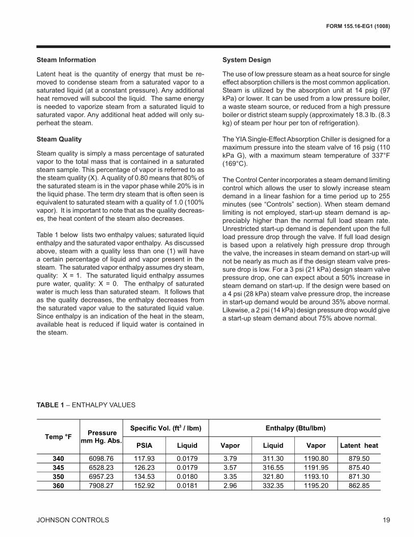
Steam Information
Latent heat is the quantity of energy that must be re-moved to condense steam from a saturated vapor to a saturated liquid (at a constant pressure). Any additional heat removed will subcool the liquid. The same energy is needed to vaporize steam from a saturated liquid to saturated vapor. Any additional heat added will only su-perheat the steam.
Steam Quality
Steam quality is simply a mass percentage of saturated vapor to the total mass that is contained in a saturated steam sample. This percentage of vapor is referred to as the steam quality (X). A quality of 0.80 means that 80% of the saturated steam is in the vapor phase while 20% is in the liquid phase. The term dry steam that is often seen is equivalent to saturated steam with a quality of 1.0 (100% vapor). It is important to note that as the quality decreas-es, the heat content of the steam also decreases. Table 1 below lists two enthalpy values; saturated liquid enthalpy and the saturated vapor enthalpy. As discussed above, steam with a quality less than one (1) will have a certain percentage of liquid and vapor present in the steam. The saturated vapor enthalpy assumes dry steam, quality: X = 1. The saturated liquid enthalpy assumes pure water, quality: X = 0. The enthalpy of saturated water is much less than saturated steam. It follows that as the quality decreases, the enthalpy decreases from the saturated vapor value to the saturated liquid value. Since enthalpy is an indication of the heat in the steam, available heat is reduced if liquid water is contained in the steam.
System Design
The use of low pressure steam as a heat source for single effect absorption chillers is the most common application. Steam is utilized by the absorption unit at 14 psig (97 kPa) or lower. It can be used from a low pressure boiler, a waste steam source, or reduced from a high pressure boiler or district steam supply (approximately 18.3 lb. (8.3 kg) of steam per hour per ton of refrigeration).
The YIA Single-Effect Absorption Chiller is designed for a maximum pressure into the steam valve of 16 psig (110 kPa G), with a maximum steam temperature of 337°F (169°C).
The Control Center incorporates a steam demand limiting control which allows the user to slowly increase steam demand in a linear fashion for a time period up to 255 minutes (see “Controls” section). When steam demand limiting is not employed, start-up steam demand is ap-preciably higher than the normal full load steam rate. Unrestricted start-up demand is dependent upon the full load pressure drop through the valve. If full load design is based upon a relatively high pressure drop through the valve, the increases in steam demand on start-up will not be nearly as much as if the design steam valve pres-sure drop is low. For a 3 psi (21 kPa) design steam valve pressure drop, one can expect about a 50% increase in steam demand on start-up. If the design were based on a 4 psi (28 kPa) steam valve pressure drop, the increase in start-up demand would be around 35% above normal. Likewise, a 2 psi (14 kPa) design pressure drop would give a start-up steam demand about 75% above normal.
��������� ����� ����� ����� ����� �����������
��� ������� ����� ������ ��� ���� ������� �������� ����� ����� ������ �� ��� ������ �������� ����� ��� ������ � ����� ������ �������� ������� ����� ������ ���� �� ������ �����
�������������!"��#�"
��$�%�$���&"�'%���*�&#�+ �,����&�:�';��*&#�+
TABLE 1 – ENTHALPY VALUES
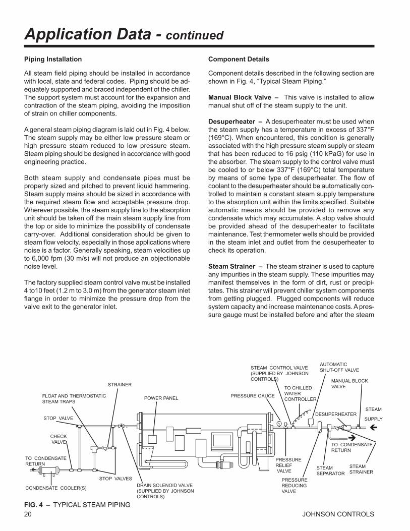
20 JOHNSON CONTROLSFIG. 4 – TYPICAL STEAM PIPING
Piping Installation
All steam field piping should be installed in accordance with local, state and federal codes. Piping should be ad-equately supported and braced independent of the chiller. The support system must account for the expansion and contraction of the steam piping, avoiding the imposition of strain on chiller components.
A general steam piping diagram is laid out in Fig. 4 below. The steam supply may be either low pressure steam or high pressure steam reduced to low pressure steam. Steam piping should be designed in accordance with good engineering practice.
Both steam supply and condensate pipes must be properly sized and pitched to prevent liquid hammering. Steam supply mains should be sized in accordance with the required steam flow and acceptable pressure drop. Wherever possible, the steam supply line to the absorption unit should be taken off the main steam supply line from the top or side to minimize the possibility of condensate carry-over. Additional consideration should be given to steam flow velocity, especially in those applications where noise is a factor. Generally speaking, steam velocities up to 6,000 fpm (30 m/s) will not produce an objectionable noise level.
The factory supplied steam control valve must be installed 4 to10 feet (1.2 m to 3.0 m) from the generator steam inlet flange in order to minimize the pressure drop from the valve exit to the generator inlet.
Component Details
Component details described in the following section are shown in Fig. 4, “Typical Steam Piping.”
Manual Block Valve – This valve is installed to allow manual shut off of the steam supply to the unit.
Desuperheater – A desuperheater must be used when the steam supply has a temperature in excess of 337°F (169°C). When encountered, this condition is generally associated with the high pressure steam supply or steam that has been reduced to 16 psig (110 kPaG) for use in the absorber. The steam supply to the control valve must be cooled to or below 337°F (169°C) total temperature by means of some type of desuperheater. The flow of coolant to the desuperheater should be automatically con-trolled to maintain a constant steam supply temperature to the absorption unit within the limits specified. Suitable automatic means should be provided to remove any condensate which may accumulate. A stop valve should be provided ahead of the desuperheater to facilitate maintenance. Test thermometer wells should be provided in the steam inlet and outlet from the desuperheater to check its operation.
Steam Strainer – The steam strainer is used to capture any impurities in the steam supply. These impurities may manifest themselves in the form of dirt, rust or precipi-tates. This strainer will prevent chiller system components from getting plugged. Plugged components will reduce system capacity and increase maintenance costs. A pres-sure gauge must be installed before and after the steam
TO CONDENSATE RETURN �
CONDENSATE COOLER(S)
CHECK VALVE
STOP VALVES
STOP VALVE
FLOAT AND THERMOSTATICSTEAM TRAPS
STRAINER
DRAIN SOLENOID VALVE(SUPPLIED BY JOHNSONCONTROLS)
POWER PANEL PRESSURE GAUGE
STEAM CONTROL VALVE(SUPPLIED BY JOHNSON CONTROLS)
TO CHILLED WATERCONTROLLER
PRESSURE REDUCING VALVE
STEAM SEPARATOR
DESUPERHEATER
MANUAL BLOCKVALVE
�TO CONDENSATE RETURN
STEAM
SUPPLY
�
STEAMSTRAINER
PRESSURERELIEF VALVE
AUTOMATICSHUT-OFF VALVE
Application Data - continued
21
FORM 155.16-EG1 (1008)
JOHNSON CONTROLS
strainer. If the pressure drop as read from these two gauges increases to an unacceptable level, the strainer should be removed and cleaned.
Steam Separator – The steam separator is installed in the steam supply line and is used to separate any liquid present in the steam. This condensate liquid would nor-mally be piped through a steam trap back to the conden-sate tank. The steam trap will prevent any steam from blowing through the separator into the condensate return system. The use of a steam separator and trap will allow dry steam to enter the unit at all times.
The system requirement is to have dry steam into the generator of the absorption chiller. If dry steam can be supplied without the use of a steam separator then it is not necessary to install one.
In cases where the chiller is located close to the boiler or is supplied with superheat, the steam reaching the chiller may already be dry. However, since any liquid present in the steam entering the chiller will reduce the heat input, it is important to include a steam separator unless it is truly not necessary.
Pressure Reducing Valve – A pressure reducing valve must be used if the steam pressure to the chiller is greater than 16 psig (110 kPaG). For applications where the steam supply pressure is known to fluctuate, it is recommended that a steam pressure regulating valve be used.
When needed, a steam pressure reducing valve suitable for dead-end service must be provided in the steam sup-ply piping ahead of the steam control valve. This pres-sure reducing valve should be sized on the basis of the pressure drop and absorption unit full load steam flow requirements, not on the basis of steam supply pipe size (which can result in an oversized valve). The pressure reducing valve should be provided with stop valves on both inlet and outlet and a full size bypass with a globe valve to permit manual operation during maintenance.
Two pressure reducing valves, one large and one small, piped in parallel may be desirable for those applications with continued operation at low loads or where highly vari-able upstream pressures exist. The smaller valve would be set at a slightly higher pressure than the large valve so it will stay open at low flow rates while the large valve closes, thus protecting the seat of the larger valve.
The use of two steps of steam pressure reduction may be desirable on applications with pressure differentials in excess of 100 psi (690 kPa). The noise generated in a single step of reduction may be objectionable.
Automatic Shut-Off Valve – This valve should shut-off 100% of the steam flow during a cycling/safety shutdown or a power failure. The Johnson Controls supplied steam control valve will remain in whatever position it happened to be in at the time of a power failure. A valve that will com-pletely shut-off steam flow to the unit during such a failure is required. This steam valve should be bubble tight.
Pressure Relief Valve – A 15 psig (103 kPaG) pres-sure relief valve should be installed to protect the steam generator vessel. The vessel must be protected from pressures above 15 psig (103 kPaG).
To prevent nuisance blowing of the relief valve, it should be set 2 or 3 psi (14 to 21 kPa) above the generator operating pressure and within code requirements. The relief valve should be sized for maximum steam flow and vented in accordance with local codes. A relief valve is not required if there is a properly sized relief valve elsewhere in the system, which will keep the system below 15 psig (103 kPaG).
Steam Cont ro l Va lve (Johnson Cont ro ls Supplied) – The steam control valve as found in the ship-loose-items, should be installed as shown in Fig. 4. This valve should be connected to the appropriate wir-ing harness and is used to control the amount of steam that enters the unit. It will modulate from 10% to 100% depending on the leaving chilled water temperature. The minimum value of 10% is set in the field. This is explained in detail in the installation manual.
Steam Inlet Pressure Indicator (If Desired) – A pres-sure gauge can be installed to allow the operator to deter-mine the inlet steam pressure to the unit. The inlet steam pressure is indicated by the micropanel, but an additional pressure gauge may be desired.
Dra in Solenoid Va lve (Johnson Contro ls Supplied) – Factory supplied device used to insure zero steam flow through the unit during shut down. This valve should be installed in a horizontal run of pipe within 2 feet (0.6 m) of the chiller condensate outlet. This valve is not supplies when a fail-close steam control valve is used. This valve is needed in addition to the Automatic Shut-Off Valve.
Vacuum Breaker (If Desired) – A vacuum breaker will often not be necessary, but they can prevent condensate build up in the generator section of the chiller at part load. A discussion of the chillers operation and the function of the vacuum breaker follows:
22 JOHNSON CONTROLS
If an atmospheric return system is used, the generator will not operate in the vacuum region, but will operate at atmo-spheric pressure at the low load conditions. Throttling of the steam valve at low load results in steam condensate back-up into the generator tubes. As the load increases, the steam valve will open and the rising steam pressure will force the condensate out of the generator. The ac-cumulation of condensate in the generator at reduced loads and subsequent drainage will have no adverse effect on absorption unit efficiency. However, the cyclical drainage of condensate from the unit will require that the main system condensate receiver be sized with sufficient additional capacity to accommodate this fluctuation (as-sumed to be equal to the absorption unit generator volume as a maximum -see Table 2 on page 22).
To avoid fluctuation in condensate return or water hammer in the generator tubes, a vacuum breaker swing check valve can be added as shown in Fig. 5 on page 24. A 3/8-inch size is sufficient to prevent condensate build-up. For safety, a pipe should be installed from the check valve to a location close to the floor or other safe place. The use of the check valve to permit air entrance into the genera-tor tubes has the disadvantage that this air must later be purged through the thermostatic element of the float trap and tends to entrain air in the condensate return.
Strainer(s) – A fine mesh strainer with blow-off valve should be provided ahead of the steam trap(s) to protect it from damage.
Float and Thermostatic Steam Trap(s) – Fig. 4 shows a typical condensate steam trap piping arrangement as used on an absorption unit. The trap serves the purpose of passing condensate, but preventing the loss of steam. A float and thermostatic steam trap is recommended for this application. It should be applied in accordance with the manufacturer’s recommendations. The trap should be located as close to the generator condensate outlet as possible in the horizontal plane. In the vertical plane, the trap should be located below the generator condensate outlet, a minimum of 12 inches (0.3 m). Preferably, the maximum possible elevation between the generator outlet and the trap should be used.
The condensate outlet line should be sized in accordance with good engineering practice for condensate at the flash point and should be kept as short and simple as possible. Stop valves should be provided ahead of the strainer and after the trap for necessary maintenance; and a full size bypass provided with globe valve for manual operation during maintenance. A full trap outlet line size connec-tion and valve should be provided for blow-off and test purposes.
The steam trap should be selected for about 1.5 times the design full steam flow rate, at the design operating pressure differential. The operating full load pressure dif-ferential: PD = SP – P1 – P2 – P3where:
PD = Trap pressure drop, psi. SP = Steam pressure, psig, at generator flange nor mally 3 psi less than the design pressure to the control valve. P1 = Condensate line pressure drop losses, psi. P2 = Check valve pressure drop loss, psi. P3 = Condensate cooler pressure drop loss, psi.
Select float capacity from manufacturer’s ratings per above recommendations.
The line from the steam trap to the condensate receiver will contain some flash vapor flowing with the condensate. This line should be as short as possible, preferably not more than 30 feet (9 m) in equivalent length. As a general rule, it should be sized according to the number of traps used and one or more sizes larger in the case of longer piping runs.
Check Valve – A check valve should be provided in the trap outlet line to prevent any possible air or condensate leakage back to the generator under reduced load operat-ing conditions.
Condensate Cooler – The use of a condensate cooler between the trap and the condensate receiver to cool the condensate below its flash is required for vacuum return systems and may be desirable, though not required, for atmospheric return systems.
The variations in condensate flow must be recognized and the cooler selected to cool the maximum flow of con-densate 5-10°F (3-6°C) below the saturation temperature of the lowest pressure in the system (atmospheric pres-sure for an atmospheric return or the lowest pressure in a vacuum return system). Sufficient coolant must be provided to cool the maximum condensate flow to the desired temperature. Coolers may be air or evaporatively cooled, providing they can produce the desired leaving condensate temperature. The flow of coolant should be automatically controlled to provide the desired leaving condensate temperature. Coolant flow could be manually set for maximum load and allowed to operate continu-ously at that level with no operating difficulties, but the poor economics of such an arrangement make automatic control preferable.
Application Data - continued
23
FORM 155.16-EG1 (1008)
JOHNSON CONTROLS
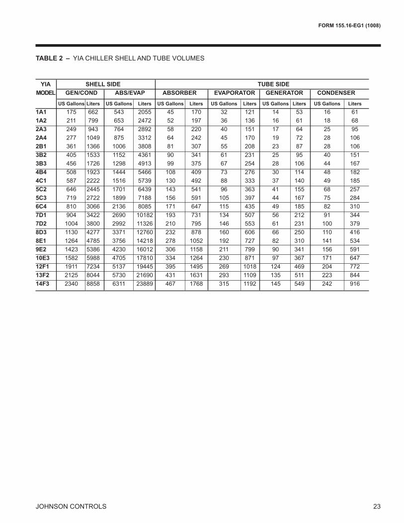
TABLE 2 – YIA CHILLER SHELL AND TUBE VOLUMES
YIA SHELL SIDE TUBE SIDE MODEL GEN/COND ABS/EVAP ABSORBER EVAPORATOR GENERATOR CONDENSER
US Gallons Liters US Gallons Liters US Gallons Liters US Gallons Liters US Gallons Liters US Gallons Liters 1A1 175 662 543 2055 45 170 32 121 14 53 16 61 1A2 211 799 653 2472 52 197 36 136 16 61 18 68 2A3 249 943 764 2892 58 220 40 151 17 64 25 95 2A4 277 1049 875 3312 64 242 45 170 19 72 28 106 2B1 361 1366 1006 3808 81 307 55 208 23 87 28 106 3B2 405 1533 1152 4361 90 341 61 231 25 95 40 151 3B3 456 1726 1298 4913 99 375 67 254 28 106 44 167 4B4 508 1923 1444 5466 108 409 73 276 30 114 48 182 4C1 587 2222 1516 5739 130 492 88 333 37 140 49 185 5C2 646 2445 1701 6439 143 541 96 363 41 155 68 257 5C3 719 2722 1899 7188 156 591 105 397 44 167 75 284 6C4 810 3066 2136 8085 171 647 115 435 49 185 82 310 7D1 904 3422 2690 10182 193 731 134 507 56 212 91 344 7D2 1004 3800 2992 11326 210 795 146 553 61 231 100 379 8D3 1130 4277 3371 12760 232 878 160 606 66 250 110 416 8E1 1264 4785 3756 14218 278 1052 192 727 82 310 141 534 9E2 1423 5386 4230 16012 306 1158 211 799 90 341 156 591 10E3 1582 5988 4705 17810 334 1264 230 871 97 367 171 647 12F1 1911 7234 5137 19445 395 1495 269 1018 124 469 204 772 13F2 2125 8044 5730 21690 431 1631 293 1109 135 511 223 844 14F3 2340 8858 6311 23889 467 1768 315 1192 145 549 242 916

24 JOHNSON CONTROLS
Auxiliary Condensate Receiver – An auxiliary con-densate receiver must be used if the main condensate receiver is located a great distance from the chiller or above the chiller. An auxiliary condensate pump is used to send condensate from the auxiliary receiver to the main condensate receiver.
The auxiliary condensate receiver should be located at floor level as close to the absorption unit as possible. A check valve in the auxiliary condensate pump discharge line is recommended where condensate backflow may occur.
Auxiliary condensate receivers with condensate pumps are available as a package. They include a float or other control to cycle the pump to suit the condensate flow. Manufacturers’ recommendations concerning selection and application of these packages should be followed.
Condensate Return Systems
Steam condensate return systems should be designed in accordance with good engineering practice for the general purpose of removing condensate from the absorp-tion unit’s generator and returning it to the boiler. Either an atmospheric or a vacuum condensate return system may be used with absorption units, as discussed earlier in this section.
A general understanding of the YORK single-effect ab-sorption unit operating requirements and characteristics is necessary before discussing the condensate return systems. The absorption chiller will operate at full load steam pressures in the 9-12 psig (62 to 88 kPa) range, down to pressures well into the vacuum region at part load. As the cooling load decreases, the chilled water controller will start closing the steam control valve, reducing both steam flow and steam pressure to the generator. At some part load point, say 75% for illustration, the steam pressure will be 0 psig, or atmospheric. With further reduction in load, the steam valve will continue to close, resulting in generator steam pressures below atmospheric pressure (providing a vacuum condensate return system is used). If an atmospheric return system is used or if a vacuum breaker is installed at the outlet of the chiller then the generator pressure will not drop below atmospheric. The use of a vacuum breaker is discussed on page 21.
Three basic types of return systems are possible: (1) a completely atmospheric system; (2) a system that allows the chiller and steam traps to function at atmospheric pressure, but the remainder of the condensate system/boiler feed to operate in a vacuum; (3) and a system that
operates entirely in a vacuum. Reference Figs. 5, 6, and 7 for typical diagrams.
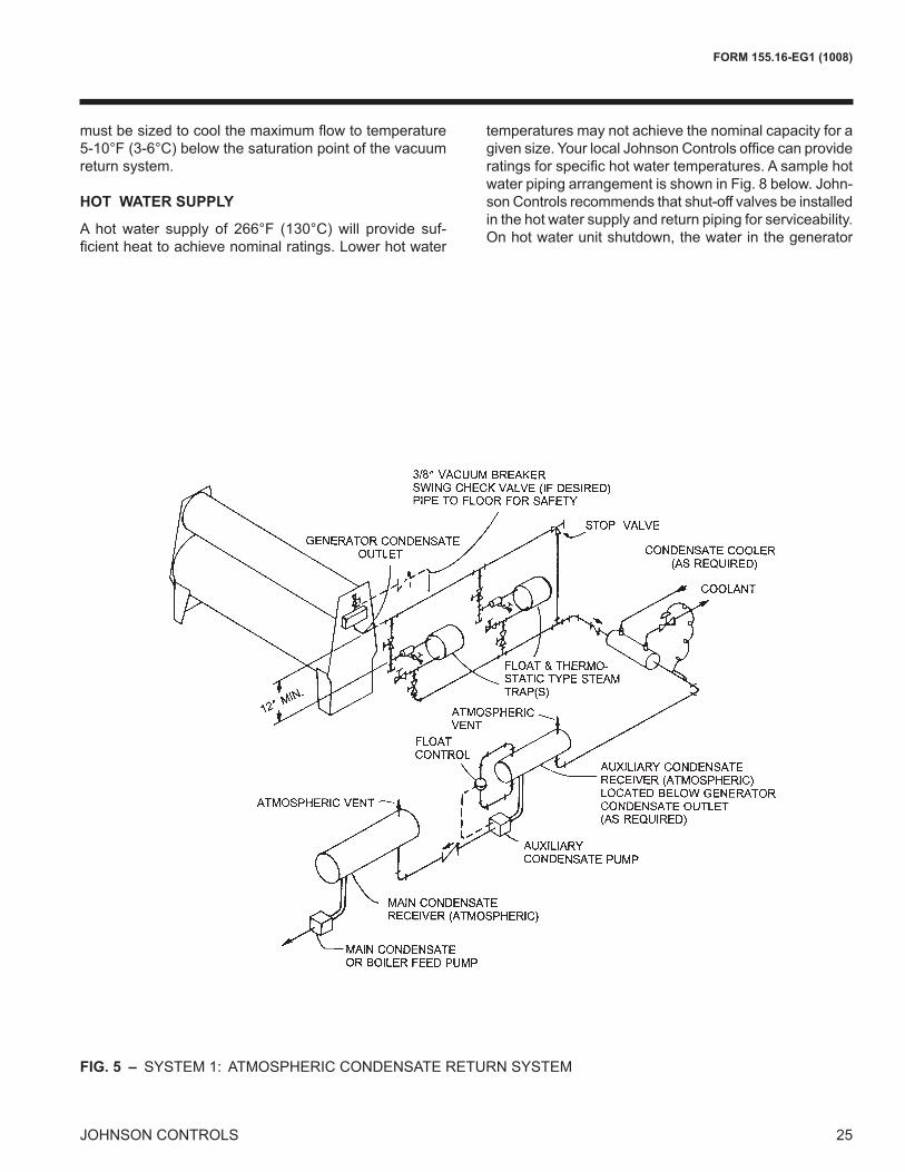
System (1) – For an entirely atmospheric system, a vacuum breaker may be installed at the outlet of the chiller (see page 21). Also in this system both the auxiliary con-densate receiver (if needed) and the main condensate re-ceiver must be vented to atmospheric pressure. The aux-iliary condensate receiver should be used on completely atmospheric systems when the main condensate receiver is located at some distance from the condensate outlet or above the condensate outlet. This system requires a float controlled pump to move condensate from the auxiliary receiver to the main condensate receiver in addition to the main condensate pump/boiler feed pump.
System (2) – Since the condensate will be at atmo-spheric pressure until it leaves the auxiliary condensate receiver, a vacuum breaker can still be used if desired (see previous paragraph). The auxiliary condensate receiver must be used in this system. The main condensate tank will no longer be vented to atmospheric pressure. A float control is still used in the auxiliary condensate receiver, however, it controls a valve instead of a pump. The low pressure, in the main tank, will draw the condensate through when the valve is opened.
For system (2), a condensate cooler must be provided in the line between the steam trap and the auxiliary receiver, as detailed under condensate cooler in the component details section. It must be sized to cool the maximum flow to a temperature 5-10°F (3-6°C) below the saturation point of the vacuum return system.
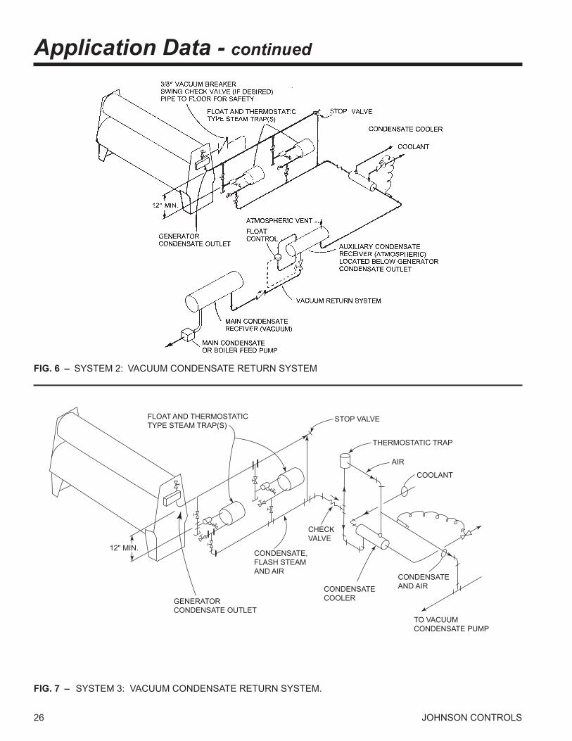
System (3) – When the low pressure steam for a YIA unit comes at or below atmospheric pressure (i.e. steam turbine exhaust), the entire system can run at a higher efficiency by using a vacuum pump on the condensate return system. At low load, when the absorption system is operating in the vacuum region, this vacuum can only be obtained if the condensate return system similarly operates in a vacuum. With a vacuum condensate re-turn system, the steam supply can be at vacuum steam pressure, rather than at a minimum steam pressure of 0 pounds gauge (as it is limited by systems (1) and (2). Discharging at a steam pressure in the vacuum region can improve a steam turbine’s economy and efficiency.
In this system a vacuum breaker can not be used.
A condensate cooler must be provided in the line between the steam trap and the auxiliary receiver, as detailed under condensate cooler in the component details section. It
Application Data - continued
25
FORM 155.16-EG1 (1008)
JOHNSON CONTROLS
FIG. 5 – SYSTEM 1: ATMOSPHERIC CONDENSATE RETURN SYSTEM
must be sized to cool the maximum flow to temperature 5-10°F (3-6°C) below the saturation point of the vacuum return system.
HOT WATER SUPPLY
A hot water supply of 266°F (130°C) will provide suf-ficient heat to achieve nominal ratings. Lower hot water
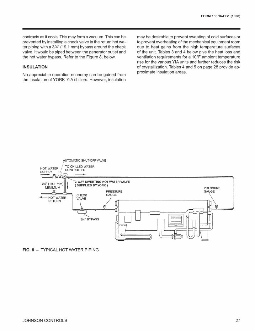
temperatures may not achieve the nominal capacity for a given size. Your local Johnson Controls office can provide ratings for specific hot water temperatures. A sample hot water piping arrangement is shown in Fig. 8 below. John-son Controls recommends that shut-off valves be installed in the hot water supply and return piping for serviceability. On hot water unit shutdown, the water in the generator
26 JOHNSON CONTROLS
FIG. 7 – SYSTEM 3: VACUUM CONDENSATE RETURN SYSTEM.
FIG. 6 – SYSTEM 2: VACUUM CONDENSATE RETURN SYSTEM
12" MIN.
GENERATORCONDENSATE OUTLET
CONDENSATE,FLASH STEAMAND AIR
FLOAT AND THERMOSTATICTYPE STEAM TRAP(S)
STOP VALVE
COOLANT
THERMOSTATIC TRAP
AIR
CHECKVALVE
CONDENSATEAND AIR
TO VACUUMCONDENSATE PUMP
CONDENSATECOOLER
Application Data - continued
27
FORM 155.16-EG1 (1008)
JOHNSON CONTROLS
FIG. 8 – TYPICAL HOT WATER PIPING
contracts as it cools. This may form a vacuum. This can be prevented by installing a check valve in the return hot wa-ter piping with a 3/4” (19.1 mm) bypass around the check valve. It would be piped between the generator outlet and the hot water bypass. Refer to the Figure 8, below.
INSULATION
No appreciable operation economy can be gained from the insulation of YORK YIA chillers. However, insulation
may be desirable to prevent sweating of cold surfaces or to prevent overheating of the mechanical equipment room due to heat gains from the high temperature surfaces of the unit. Tables 3 and 4 below give the heat loss and ventilation requirements for a 10°F ambient temperature rise for the various YIA units and further reduces the risk of crystallization. Tables 4 and 5 on page 28 provide ap-proximate insulation areas.
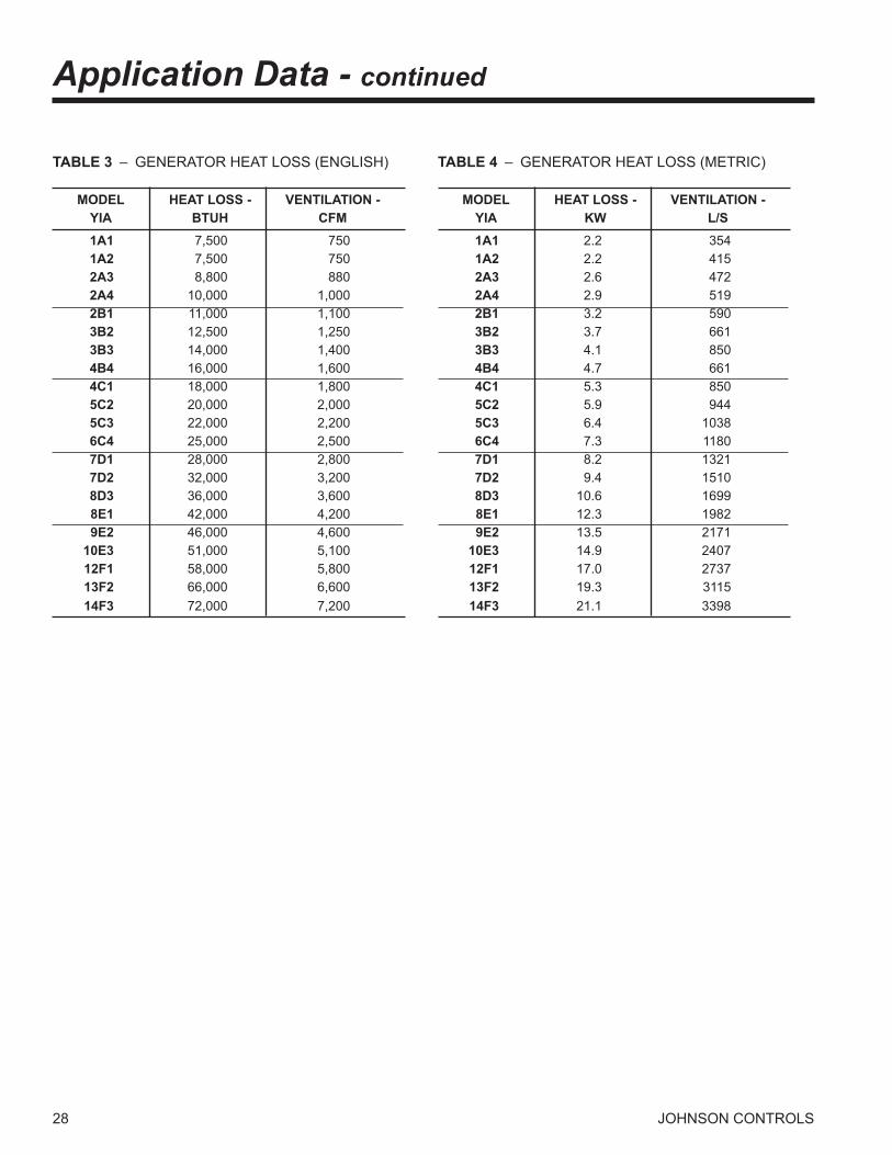
28 JOHNSON CONTROLS
TABLE 3 – GENERATOR HEAT LOSS (ENGLISH)
MODEL HEAT LOSS - VENTILATION - YIA BTUH CFM 1A1 7,500 750 1A2 7,500 750 2A3 8,800 880 2A4 10,000 1,000 2B1 11,000 1,100 3B2 12,500 1,250 3B3 14,000 1,400 4B4 16,000 1,600 4C1 18,000 1,800 5C2 20,000 2,000 5C3 22,000 2,200 6C4 25,000 2,500 7D1 28,000 2,800 7D2 32,000 3,200 8D3 36,000 3,600 8E1 42,000 4,200 9E2 46,000 4,600 10E3 51,000 5,100 12F1 58,000 5,800 13F2 66,000 6,600 14F3 72,000 7,200
TABLE 4 – GENERATOR HEAT LOSS (METRIC)
MODEL HEAT LOSS - VENTILATION - YIA KW L/S 1A1 2.2 354 1A2 2.2 415 2A3 2.6 472 2A4 2.9 519 2B1 3.2 590 3B2 3.7 661 3B3 4.1 850 4B4 4.7 661 4C1 5.3 850 5C2 5.9 944 5C3 6.4 1038 6C4 7.3 1180 7D1 8.2 1321 7D2 9.4 1510 8D3 10.6 1699 8E1 12.3 1982 9E2 13.5 2171 10E3 14.9 2407 12F1 17.0 2737 13F2 19.3 3115 14F3 21.1 3398
Application Data - continued
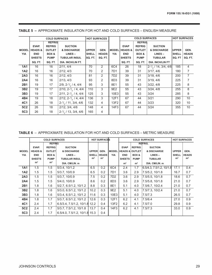
29
FORM 155.16-EG1 (1008)
JOHNSON CONTROLS
COLD SURFACES HOT SURFACES COLD SURFACES HOT SURFACES REFRIG REFRIG. EVAP. REFRIG SUCTION EVAP REFRIG SUCTION MODEL HEADS & OUTLET & DISCHARGE UPPER GEN. MODEL HEADS & OUTLET & DISCHARGE UPPER GEN. YIA END BOX & LINES – SHELL HEADS YIA END BOX & LINES – SHELL HEADS SHEETS PUMP TUBULAR INSUL SQ. FT. SQ. FT. SHEETS PUMP TUBULAR SQ. FT SQ. FT.
SQ. FT. SQ. FT. DIA. INCH/LIN FT. SQ. FT. SQ. FT. DIA. INCH/LIN FT
1A1 16 16 2/11, 4/4 70 2 6C4 26 18 2-1/2 / 14, 3/4, 4/6 185 4 1A2 16 16 2/12, 4/3 70 2 7D1 39 31 3/17, 4/6 180 7 2A3 16 16 2/12, 4/3 81 2 7D2 39 31 3/18, 4/6 200 7 2A4 16 16 2/13, 4/3 93 2 8D3 39 31 3/19, 4/6 225 7 2B1 19 17 2/9, 2-1/2 / 4, 4/4 95 3 8E1 55 43 3/22, 4/8 225 8 3B2 19 17 2/10, 2-1/2 / 4, 4/4 110 3 9E2 55 43 3/24, 4/8 255 8 3B3 19 17 2/11, 2-1/2 / 4, 4/4 125 3 10E3 55 43 3/24 285 8 4B4 19 18 2/12, 2-1/2 / 4, 4/4 136 3 12F1 67 44 3/21 290 10 4C1 26 18 2-1/2 / 11, 3/4, 4/6 132 4 13F2 67 44 3/23 320 10 5C2 26 18 2/12, 3/4, 4/6 148 4 14F3 67 44 3/24 355 10 5C3 26 18 2-1/2 / 13, 3/4, 4/6 165 4
COLD SURFACES HOT SURFACES COLD SURFACES HOT SURFACES REFRIG REFRIG. EVAP. REFRIG SUCTION EVAP REFRIG SUCTION MODEL HEADS & OUTLET & DISCHARGE UPPER GEN. MODEL HEADS & OUTLET & DISCHARGE UPPER GEN. YIA END BOX & LINES – SHELL HEADS YIA END BOX & LINES – SHELL HEADS SHEETS PUMP TUBULAR INSUL m2 m2 SHEETS PUMP TUBULAR m2 m2
m2 m2
DIA. CM/LIN. m m2 m2 DIA. CM/LIN. m
1A1 1.5 1.5 5/3.4, 10/1.2 6.5 0.2 6C4 2.4 1.7 6.5/4.3, 7.5/1.2, 10/1.8 17.1 0.4 1A2 1.5 1.5 5/3.7, 10/0.9 6.5 0.2 7D1 3.6 2.9 7.5/5.2, 10/1.8 16.7 0.7 2A3 1.5 1.5 5/3.7, 10/0.9 7.5 0.2 7D2 3.6 2.9 7.5/5.5, 10/1.8 18.6 0.7 2A4 1.5 1.5 5/4.0, 10/0.9 8.6 0.2 8D3 3.6 2.9 7.5/5.8, 10/1.8 21.0 0.7 2B1 1.8 1.6 5/2.7, 6.5/1.2, 10/1.2 8.8 0.3 8E1 5.1 4.0 7.5/6.7, 10/2.4 21.0 0.7 3B2 1.8 1.6 5/3.0, 6.5/1.2, 10/1.2 10.2 0.3 9E2 5.1 4.0 7.5/7.3, 10/2.4 21.0 0.7 3B3 1.8 1.6 5/3.4, 6.5/1.2, 10/1.2 11.6 0.3 10E3 5.1 4.0 7.5/7.3 26.5 0.7 4B4 1.8 1.7 5/3.7, 6.5/1.2, 10/1.2 12.6 0.3 12F1 6.2 4.1 7.5/6.4 27.0 0.9 4C1 2.4 1.7 6.5/3.4, 7.5/1.2, 10/1.8 12.2 0.4 13F2 6.2 4.1 7.5/7.0 29.8 0.9 5C2 2.4 1.7 5/3.7, 7.5/1.2, 10/1.8 13.7 0.4 14F3 6.2 4.1 7.5/7.3 33.0 0.9 5C3 2.4 1.7 6.5/4.0, 7.5/1.2, 10/1.8 15.3 0.4
TABLE 5 – APPROXIMATE INSULATION FOR HOT AND COLD SURFACES – ENGLISH MEASURE
TABLE 6 – APPROXIMATE INSULATION FOR HOT AND COLD SURFACES – METRIC MEASURE
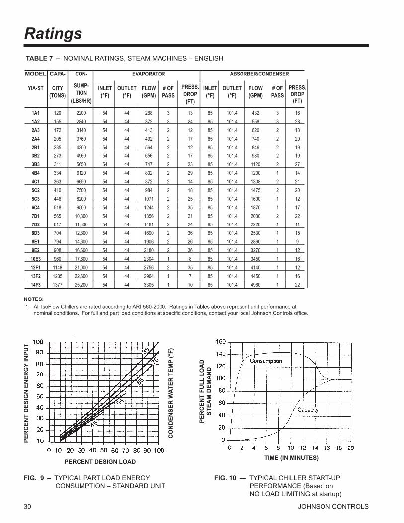
30 JOHNSON CONTROLS
MODEL CAPA- CON- EVAPORATOR ABSORBER/CONDENSER YIA-ST CITY SUMP- INLET OUTLET FLOW # OF PRESS. INLET OUTLET FLOW # OF PRESS. (TONS) TION (°F) (°F) (GPM) PASS DROP (°F) (°F) (GPM) PASS DROP (LBS/HR) (FT) (FT) 1A1 120 2200 54 44 288 3 13 85 101.4 432 3 16 1A2 155 2840 54 44 372 3 24 85 101.4 558 3 28 2A3 172 3140 54 44 413 2 12 85 101.4 620 2 13 2A4 205 3760 54 44 492 2 17 85 101.4 740 2 20 2B1 235 4300 54 44 564 2 12 85 101.4 846 2 19 3B2 273 4960 54 44 656 2 17 85 101.4 980 2 19 3B3 311 5650 54 44 747 2 23 85 101.4 1120 2 27 4B4 334 6120 54 44 802 2 29 85 101.4 1200 1 14 4C1 363 6650 54 44 872 2 14 85 101.4 1308 2 21 5C2 410 7500 54 44 984 2 18 85 101.4 1475 2 20 5C3 446 8200 54 44 1071 2 25 85 101.4 1600 1 12 6C4 518 9500 54 44 1244 2 35 85 101.4 1870 1 17 7D1 565 10,300 54 44 1356 2 21 85 101.4 2030 2 22 7D2 617 11,300 54 44 1481 2 24 85 101.4 2220 1 11 8D3 704 12,800 54 44 1690 2 36 85 101.4 2530 1 15 8E1 794 14,600 54 44 1906 2 26 85 101.4 2860 1 9 9E2 908 16,600 54 44 2180 2 36 85 101.4 3270 1 12 10E3 960 17,600 54 44 2304 1 8 85 101.4 3450 1 16 12F1 1148 21,000 54 44 2756 2 35 85 101.4 4140 1 12 13F2 1235 22,600 54 44 2964 1 7 85 101.4 4450 1 16 14F3 1377 25,200 54 44 3305 1 10 85 101.4 4960 1 22
NOTES: 1. All IsoFlow Chillers are rated according to ARI 560-2000. Ratings in Tables above represent unit performance at nominal conditions. For full and part load conditions at specific conditions, contact your local Johnson Controls office.
TABLE 7 – NOMINAL RATINGS, STEAM MACHINES – ENGLISH
Ratings
FIG. 9 – TYPICAL PART LOAD ENERGY CONSUMPTION – STANDARD UNIT
FIG. 10 — TYPICAL CHILLER START-UP PERFORMANCE (Based on NO LOAD LIMITING at startup)
PER
CEN
T FU
LL L
OA
DST
EAM
DEM
AN
D
PERCENT DESIGN LOAD
PER
CEN
T D
ESIG
N E
NER
GY
INPU
T
CO
ND
ENSE
R W
ATER
TEM
P (°
F)
TIME (IN MINUTES)
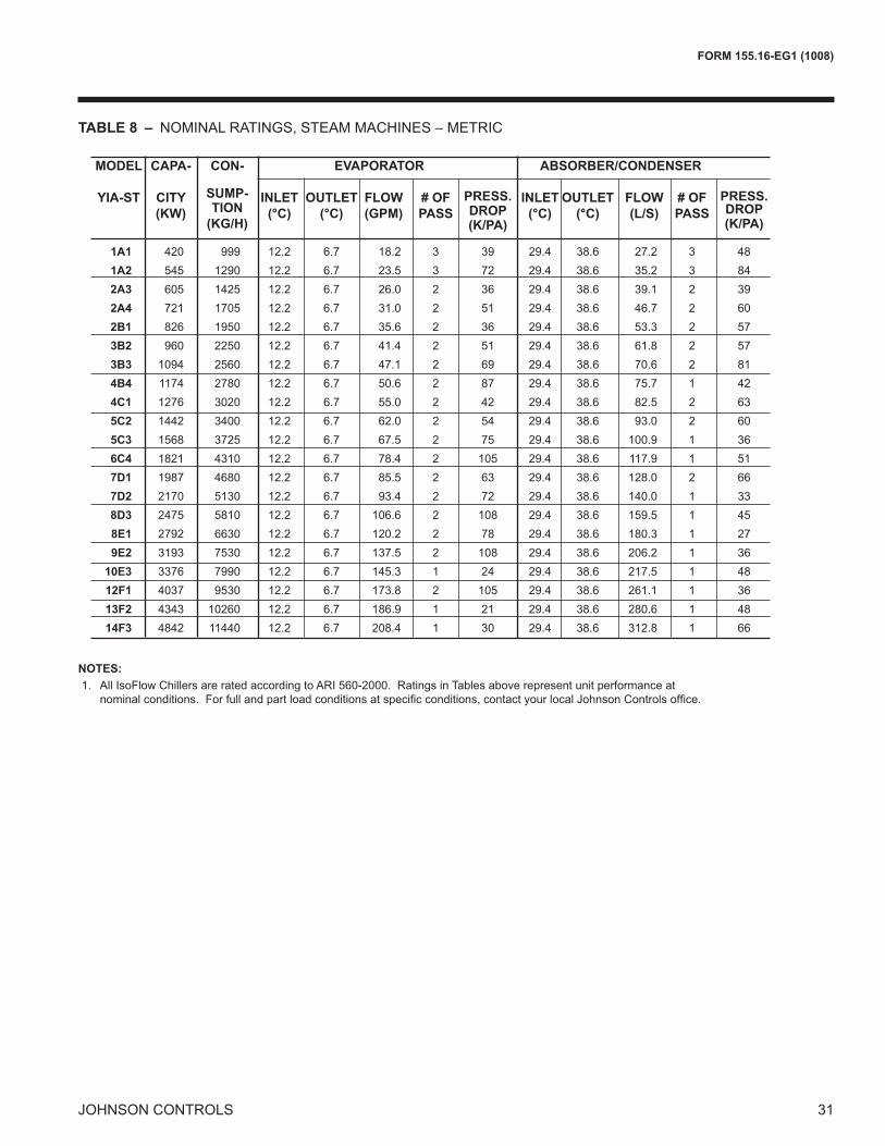
31
FORM 155.16-EG1 (1008)
JOHNSON CONTROLS
MODEL CAPA- CON- EVAPORATOR ABSORBER/CONDENSER YIA-ST CITY SUMP- INLET OUTLET FLOW # OF PRESS. INLET OUTLET FLOW # OF PRESS. (KW) TION (°C) (°C) (GPM) PASS DROP (°C) (°C) (L/S) PASS DROP (KG/H) (K/PA) (K/PA) 1A1 420 999 12.2 6.7 18.2 3 39 29.4 38.6 27.2 3 48 1A2 545 1290 12.2 6.7 23.5 3 72 29.4 38.6 35.2 3 84 2A3 605 1425 12.2 6.7 26.0 2 36 29.4 38.6 39.1 2 39 2A4 721 1705 12.2 6.7 31.0 2 51 29.4 38.6 46.7 2 60 2B1 826 1950 12.2 6.7 35.6 2 36 29.4 38.6 53.3 2 57 3B2 960 2250 12.2 6.7 41.4 2 51 29.4 38.6 61.8 2 57 3B3 1094 2560 12.2 6.7 47.1 2 69 29.4 38.6 70.6 2 81 4B4 1174 2780 12.2 6.7 50.6 2 87 29.4 38.6 75.7 1 42 4C1 1276 3020 12.2 6.7 55.0 2 42 29.4 38.6 82.5 2 63 5C2 1442 3400 12.2 6.7 62.0 2 54 29.4 38.6 93.0 2 60 5C3 1568 3725 12.2 6.7 67.5 2 75 29.4 38.6 100.9 1 36 6C4 1821 4310 12.2 6.7 78.4 2 105 29.4 38.6 117.9 1 51 7D1 1987 4680 12.2 6.7 85.5 2 63 29.4 38.6 128.0 2 66 7D2 2170 5130 12.2 6.7 93.4 2 72 29.4 38.6 140.0 1 33 8D3 2475 5810 12.2 6.7 106.6 2 108 29.4 38.6 159.5 1 45 8E1 2792 6630 12.2 6.7 120.2 2 78 29.4 38.6 180.3 1 27 9E2 3193 7530 12.2 6.7 137.5 2 108 29.4 38.6 206.2 1 36 10E3 3376 7990 12.2 6.7 145.3 1 24 29.4 38.6 217.5 1 48 12F1 4037 9530 12.2 6.7 173.8 2 105 29.4 38.6 261.1 1 36 13F2 4343 10260 12.2 6.7 186.9 1 21 29.4 38.6 280.6 1 48 14F3 4842 11440 12.2 6.7 208.4 1 30 29.4 38.6 312.8 1 66
TABLE 8 – NOMINAL RATINGS, STEAM MACHINES – METRIC
NOTES: 1. All IsoFlow Chillers are rated according to ARI 560-2000. Ratings in Tables above represent unit performance at nominal conditions. For full and part load conditions at specific conditions, contact your local Johnson Controls office.

32 JOHNSON CONTROLS
Ratings - continued
°F°C
Leaving Chilled Water Temp
4 6 7 8 9
FIG. 11 – TYPICAL CHILLER COOLING CAPACITY FOR REQUIRED LCHWT
FIG. 12 – TYPICAL CHILLER COOLING CAPACITY FOR AVAILABLE STEAM INLET PRESSURE
FIG. 13 – TYPICAL CHILLER STEAM CONSUMPTION FOR LCHWT
°F°C
Leaving Chilled Water Temp Leaving Chilled Water Temp
Chi
ller S
team
Con
sum
ptio
n%
of N
omin
al F
ull L
oad
Con
sum
ptio
n
4 6 7 8 9
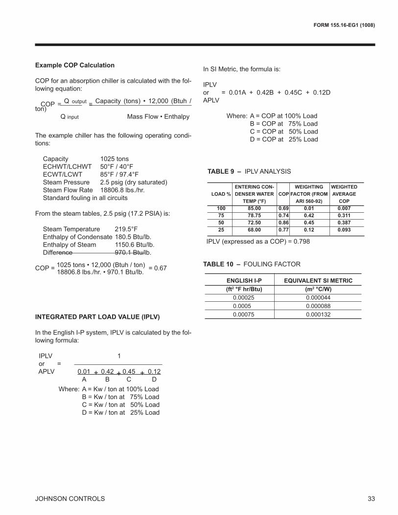
33
FORM 155.16-EG1 (1008)
JOHNSON CONTROLS
In SI Metric, the formula is:
IPLVor = 0.01A + 0.42B + 0.45C + 0.12DAPLV
Where: A = COP at 100% Load B = COP at 75% Load C = COP at 50% Load D = COP at 25% Load
TABLE 10 – FOULING FACTOR
ENGLISH I-P EQUIVALENT SI METRIC (ft2 °F hr/Btu) (m2 °C/W) 0.00025 0.000044 0.0005 0.000088 0.00075 0.000132
Example COP Calculation
COP for an absorption chiller is calculated with the fol-lowing equation:
COP = Q output = Capacity (tons) • 12,000 (Btuh / ton) Q input Mass Flow • Enthalpy
The example chiller has the following operating condi-tions:
Capacity 1025 tonsECHWT/LCHWT 50°F / 40°FECWT/LCWT 85°F / 97.4°FSteam Pressure 2.5 psig (dry saturated)Steam Flow Rate 18806.8 lbs./hr.Standard fouling in all circuits
From the steam tables, 2.5 psig (17.2 PSIA) is:
Steam Temperature 219.5°FEnthalpy of Condensate 180.5 Btu/lb.Enthalpy of Steam 1150.6 Btu/lb.Difference 970.1 Btu/lb.
COP = 1025 tons • 12,000 (Btuh / ton) = 0.67 18806.8 lbs./hr. • 970.1 Btu/lb.
Where: A = Kw / ton at 100% Load B = Kw / ton at 75% Load C = Kw / ton at 50% Load D = Kw / ton at 25% Load
INTEGRATED PART LOAD VALUE (IPLV)
In the English I-P system, IPLV is calculated by the fol-lowing formula:
TABLE 9 – IPLV ANALYSIS ENTERING CON- WEIGHTING WEIGHTED LOAD % DENSER WATER COP FACTOR (FROM AVERAGE TEMP (°F) ARI 560-92) COP 100 85.00 0.69 0.01 0.007 75 78.75 0.74 0.42 0.311 50 72.50 0.86 0.45 0.387 25 68.00 0.77 0.12 0.093
IPLV (expressed as a COP) = 0.798
+++
IPLV 1 or = APLV 0.01 0.42 0.45 0.12 A B C D
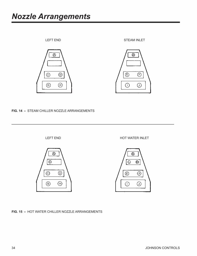
34 JOHNSON CONTROLS
FIG. 14 – STEAM CHILLER NOZZLE ARRANGEMENTS
LEFT END STEAM INLET
LEFT END HOT WATER INLET
Nozzle Arrangements
FIG. 15 – HOT WATER CHILLER NOZZLE ARRANGEMENTS

35
FORM 155.16-EG1 (1008)
JOHNSON CONTROLS
TABLE 13 – HOT WATER GENERATOR NOZZLE ARRANGEMENTS
NUMBER NOZZLE IN OUT PASSES ARRANGEMENT
1 HW1 L K 2 HW2 L M 3 HW3 L K
TABLE 11 – EVAPORATOR PASS ARRANGEMENTS
NUMBER NOZZLE IN OUT PASSES ARRANGEMENT
E1 C E 1,3 E2 D F E3 E C E4 F D E5 C D 2,4 E6 D C E7 E F E8 F E
TABLE 12 – ABSORBER/CONDENSER ARRANGEMENTS
NUMBER OF NOZZLE ABSORBER CONDENSER ABSORBER PASSES ARRANGEMENT IN OUT IN OUT
AC1 G I B A 1,3 AC2 I G A B AC3 H J B A AC4 J H A B AC5 G H A B 2 AC6 H G A B AC7 I J B A AC8 J I B A
NOTES: 1. Marine Waterboxes are available on E2, E4, E7, & E8 only. 2. 4 Pass Evaporators are not available on “F” family of chillers.
NOTES: 1. Three pass Absorber not available on “E” & “F” family chillers. 2. Marine Waterboxes not available for 1 Pass Absorber in “A” family chillers.
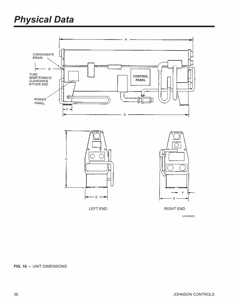
36 JOHNSON CONTROLS
LD00688(R)
FIG. 16 – UNIT DIMENSIONS
LEFT END RIGHT END
CONTROL PANEL
G
Physical Data
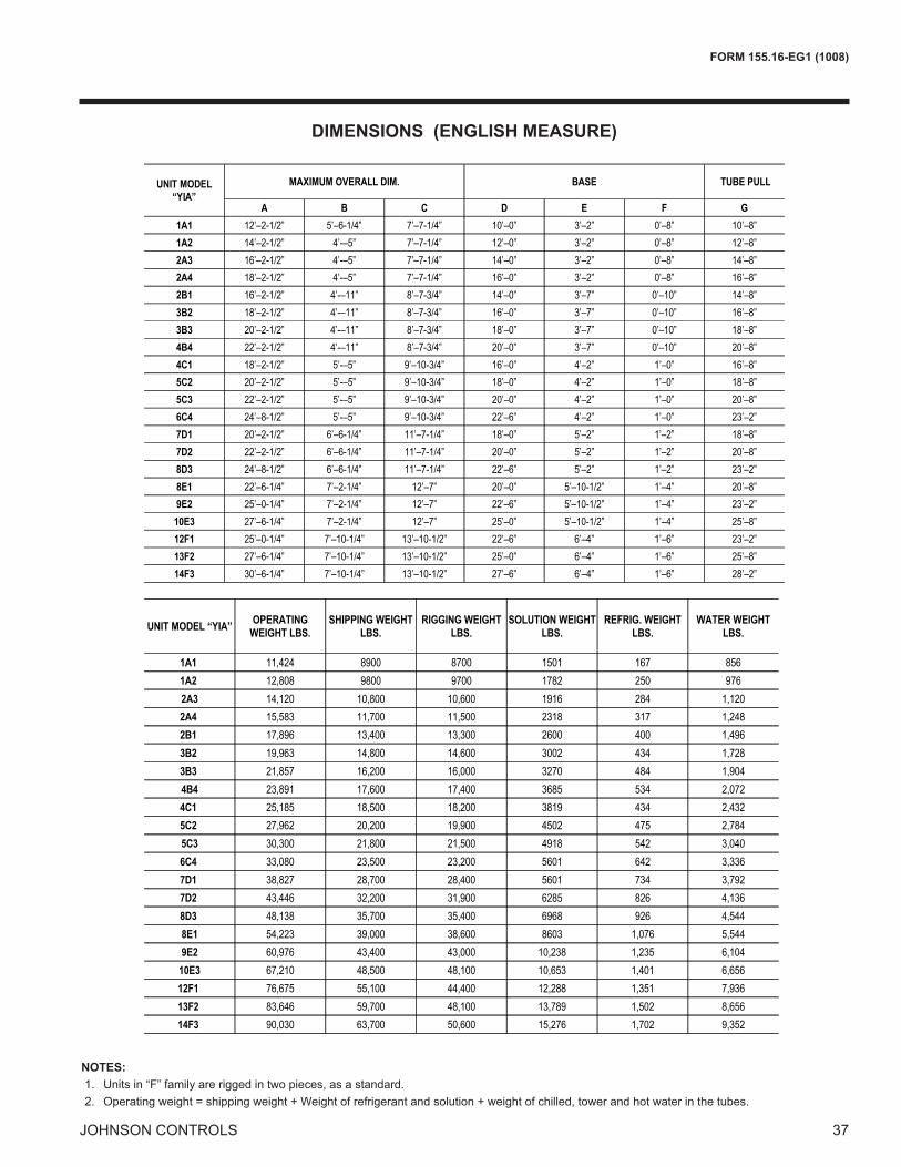
37
FORM 155.16-EG1 (1008)
JOHNSON CONTROLS
DIMENSIONS (ENGLISH MEASURE)
NOTES: 1. Units in “F” family are rigged in two pieces, as a standard. 2. Operating weight = shipping weight + Weight of refrigerant and solution + weight of chilled, tower and hot water in the tubes.
���������� ���
���� ������ ���� ��� ��� �� ������ ������ ���� ��� ��� �� ����� ������ ������ ������ ���� ��� ��������� ���� ����� ����� ���� �� ��������� ����� ������ ������ ���� ��� ��������� ������ ������ ������ ���� ��� �������� ���� ������ ������ ��� ��� �������� ������ ����� ����� ��� �� �������� ���� ����� ������ ���� ��� ��������� ����� ������ ������ ��� � ������� ������ ������ ����� ���� �� ��������� ������ ����� ������ ��� ��� �������� ����� ����� ������ ��� �� ������� ������ ������ ������ ��� ��� �������� ������ ���� ����� ���� ��� ������ ����� ������ ������ ���� ���� ����� ����� ������ ������ ������ ���� �����
��� ����� ����� ������ ����� ����� ��������� ��� ���� ������ ������ ���� ��������� ������ ���� ������ ����� ���� ��������� ������ ����� ����� ���� ���� ����
���������!��"����$%
$"�������!��"����$%
��������!��"����$%
$��������!��"����$%
�����%�!��"����$%
!����!��"����$%
���������������� �� ��� ���
� � � � ���� ���������� ������� �������� � �� � ����� ���� � ������� ��������� �������� ���� � ����� ���� ��������� ��������� �������� ��� � ����� ���� �������� ���������� �������� ��� � ����� ���� ������ � ��������� �������� ��� � ����� ��� � ������ � ���������� �������� ��� � ����� ��� � ������ � � �������� �������� ���� � ����� ��� � ������� � ���������� �������� � �� � ����� ��� � � ������� ���������� ���� ���� ��� � ���� ��� � �������� � �������� ���� ���� ���� � ���� ��� � ��������� ���������� ���� ���� � �� � ���� ��� � � ������� ��������� ���� ���� ����� ���� ��� � ��������� � �������� ������ ��������� ���� � ����� ����� ��������� ���������� ������ ��������� � �� � ����� ����� � ������� ��������� ������ ��������� ����� ����� ����� �������� �������� �������� ������ � �� � ���� ����� ���� � ������ ���� ���� �������� ������ ����� ���� ����� ���� ��������� �������� �������� ������ ���� � ���� ����� ���� ���������� ���� ���� ���� ���� ����� ����� ����� ��� ���� ���������� �������� ���� ���� ����� ����� ���� � ��� ���� ���������� � ������ ���� ���� ����� ����� ����� ��� ���� ������
���������� ��!
���������������������������������������������������������������

38 JOHNSON CONTROLS
DIMENSIONS (METRIC MEASURE)
NOTES: 1. Units in “F” family are rigged in two pieces, as a standard. 2. Operating weight = shipping weight + Weight of refrigerant and solution + weight of chilled, tower and hot water in the tubes.
Physical Data - continued
���������������� �� ��� ���
� � � � ���� ���� ���� ���� ��� �� �� ������ ��� ��� ���� ���� �� �� ������� ��� ��� ���� ���� �� �� ������� �� ��� ���� ���� �� �� ���� � ��� ��� ��� ���� ���� � ����� � �� ��� ��� ���� ���� � ���� � ���� ��� ��� �� ���� � ��� � ��� ��� ��� ���� ���� � ������� �� ���� ���� ���� ���� �� ������ ���� ���� ���� �� ���� �� ����� ��� ���� ���� ���� ���� �� ������� �� ���� ���� ���� ���� �� ������� ���� �� ��� �� ��� ��� ����� ��� �� ��� ���� ��� ��� ������� �� �� ��� ���� ��� ��� ������ ��� ��� ���� ���� ���� ��� ������ ��� ��� ���� ���� ���� ��� ������� ���� ��� ���� ���� ���� ��� �������� ��� ���� ��� ���� ��� ��� �������� ���� ���� ��� ���� ��� ��� �������� ��� ���� ��� ��� ��� ��� ��
���������� ��!
���������� ���
���� ���� ��� ���� ��� � ������� ���� ���� ���� ��� ��� ������ ���� ���� ���� ��� ��� ������� ��� ��� ���� ���� ��� ������� ��� ��� ���� ��� ��� ������ ���� ��� ���� ���� �� ������ ���� ��� �� ���� ��� ������ ���� ��� ��� ��� ��� ������� ����� ���� ���� ��� �� �������� ����� ���� ���� ���� ��� ������� ���� ���� ��� ���� ��� ������� ����� ����� ����� ���� ��� ������� ���� ����� ����� ���� ��� ������ ��� ����� ���� ���� �� ������ ����� ����� ���� ���� ��� ������ ����� ���� ���� ���� ��� ������ ���� ����� ����� ���� ��� ���
��� ����� ����� ����� ���� ��� ��������� ��� ����� ����� ��� ��� ��������� ���� ��� ����� ���� ��� ��������� ���� ����� ����� ���� � ����
���������!��"�����&
�"�������!��"�����&
��������!��"�����&
���������!��"�����&
�����&�!��"�����&
!����!��"�����&

39
FORM 155.16-EG1 (1008)
JOHNSON CONTROLS
Electrical DataTABLE 14 – ELECTRICAL RATINGS
��������� � ������������ � �������� ���������
��� ��� ��� ��� ��� ���
���
������������ �� � �� � � �� ��� �� �� � �������� � �� � �� �� �� ��� �� �� � �������� �� �� �� �� �� �� �� �� � �������� �� �� �� ��� � �� �� �� � �������� � �� � ��� �� �� �� �� � �������� � �� � �� � �� �� � �
���
������������ �� � �� � � �� ��� �� �� � �������� � �� � �� �� �� ��� �� �� � �������� �� �� �� �� �� �� �� �� � �������� �� �� �� ��� � �� �� �� � �������� � �� � ��� �� �� �� �� � �������� � �� � �� � �� �� � �
���
������������ �� � �� � � �� ��� �� �� � �������� � �� � �� �� �� ��� �� �� � �������� �� �� �� �� �� �� �� �� � �������� � �� �� ��� � �� �� �� � �������� � �� � ��� �� �� �� �� � �������� � �� � �� � �� �� � �
���
������������ � � �� � � �� ��� �� �� � �������� � �� � �� �� � ��� �� �� � �������� � �� �� �� �� �� �� �� � �������� �� ��� �� ��� � �� �� �� � �������� � ��� � ��� �� �� �� �� � �������� � �� � �� � �� �� � �
���
������������ �� � �� � � �� ��� �� �� � �������� � �� � �� �� �� ��� �� �� � �������� �� �� �� �� �� �� �� �� � �������� �� ��� �� ��� � �� �� �� � �������� � ��� � ��� �� �� �� �� � �������� � �� � �� � �� �� � �
���
������������ �� �� �� � � �� ��� �� �� ���������� �� � �� �� �� ��� �� �� ���������� �� �� �� �� �� �� �� �� ���������� �� ��� �� ��� � �� �� �� ���������� � �� � ��� �� �� �� �� ���������� �� �� � �� � �� �� �� ��
���
������������ �� �� �� � � �� ��� �� �� ���������� �� � �� �� �� ��� �� �� ���������� � �� �� �� �� �� �� �� ���������� �� � �� ��� � �� �� �� ���������� � �� � ��� �� �� �� �� ���������� �� �� � �� � �� �� �� ��
���
������������ �� �� �� � � �� ��� �� �� ���������� �� � �� �� �� ��� �� �� ���������� � �� �� �� �� �� �� �� ���������� �� � �� ��� � �� �� �� ���������� � �� � ��� �� �� �� �� ���������� �� �� � �� � �� �� �� ��
� �
������������ �� �� �� � � �� ��� �� �� ���������� �� � �� �� �� ��� �� �� ���������� � �� �� �� �� �� �� �� ���������� �� � �� ��� � �� �� �� ���������� � �� � ��� �� �� �� �� ���������� �� �� � �� � �� �� �� ��
! �
������������ �� �� �� � � �� ��� �� �� ���������� �� � �� �� �� ��� �� �� ���������� �� �� �� �� �� �� �� ���������� �� �� �� ��� � ��� �� �� ���������� � �� � ��� �� �� �� �� ���������� �� �� � �� � �� �� �� ��
"�����#����
�����������'*� *+,:
����������;�������;��<
=�';����;��>��;
���'�����'�������:
��?*=���@���J��'����'�����'�������:
NOTES: 1. Table 14 is appropriate for both Steam and Hot Water Units. 2. Purge pump ratings are for the Welch model 1402. 3. Disconnect size in accordance with NEC. A Johnson Controls supplied 100 amp, non-fused, unit disconnect switch is in the power panel.

40 JOHNSON CONTROLS
Electrical Data - continuedTABLE 14 – ELECTRICAL RATINGS (Cont’d)
NOTES: 1. Table 14 is appropriate for both Steam and Hot Water Units. 2. Purge pump ratings are for the Welch model 1402. 3. Disconnect size in accordance with NEC. A Johnson Controls supplied 100 amp, non-fused, unit disconnect switch is in the power panel.
������������ �������������� ���������������
��� ��� ��� ��� ��� ���
� !
������������ ��� ��� ��� ���� ��� ���� ���� ���� ���� ������� ���� ��� ���� ���� ��� ��� ��� ���� ���� � ����� ���� ���� ��� ��� ��� ��� �� ��� ���� ��������� ��� ���� �� ���� ��� ��� �� ��� ���� ��������� ��� ���� ��� ��� ��� ��� ���� ��� ��� ������� � �� ��� ���� ��� ��� ��� ��� ���� �
"#�
������ ���� ���� �� ���� ���� ��� ���� ���� ���� ���� ������� ���� ��� ���� ���� ��� ��� ��� ���� ���� � ����� ���� ���� ��� ��� ��� ��� �� ��� ���� ��������� ��� ���� �� ���� ��� ��� �� ��� ���� ��������� ��� ���� ��� ��� ��� ��� ���� ��� ��� ������� � �� ��� ���� ��� ��� ��� ��� ���� �
���
������ ���� �� ���� ���� ���� ��� ���� ���� ����� ���� �������� ��� �� �� ���� ���� ��� ��� ���� ���� ��� �� ����� ���� ���� ��� ��� ��� ��� �� ��� ���� ��������� ��� ���� �� ���� ��� ��� �� ��� ���� ��������� ���� ���� ��� ��� ��� ��� � �� ��� ���� �������� ���� ��� ��� ���� ��� ��� ���� ��� ��� ��
���
������ ���� �� ���� ���� ���� ��� ���� ���� ����� ���� �������� ��� �� �� ���� ���� ��� ��� ���� ���� ��� �� ����� ���� ���� ��� �� ��� ��� �� ���� ���� ����������� ��� ���� ���� ��� ��� ��� �� ���� ���� ����������� ���� ���� ��� ��� ��� ��� � �� ��� ���� �������� ���� ��� ��� ���� ��� ��� ���� ��� ��� ��
��
������ ���� ��� �� �� ���� �� ��� ���� ��� ����� ����� ���������� �� ���� ���� ��� ��� ��� ��� ����� ����� ���� ����� ���� ���� ���� ���� ��� ��� ��� ���� ���� ���������� ��� ���� ��� ���� ��� ��� �� ���� ���� ���������� � �� ���� ��� ���� ��� ��� �� ���� ���� ���������� ���� ���� � �� ��� ��� ��� ��� ���� ����
���
������ ���� ��� �� �� �� ���� ��� ���� ���� ����� ����� ��������� �� ���� ��� �� �� ��� ��� ��� ����� ����� ��� ����� ���� ���� ���� ���� ��� ��� ��� ���� ���� ���������� ��� ���� ��� ���� ��� ��� �� ���� ���� ���������� � �� ���� ���� ���� ��� ��� ��� ���� ���� ��������� ���� ���� ���� ��� ��� ��� �� ���� ���� ����
����
������ ���� �� ���� �� ���� ��� ���� ��� ����� ����� ��������� ��� �� �� ��� �� �� ��� ��� ��� ����� ����� ��� ����� ���� ���� ���� ���� ��� ��� ��� ���� ���� ���������� ��� ���� ��� ���� ��� ��� �� ���� ���� ���������� ���� ���� ���� ���� ��� ��� �� ���� ���� ��������� ���� ��� ���� ��� ��� ��� ��� ���� ���� ���
� �����������
���������������� ���
��!�"#"����$#���
%"&�$��'
���$�!!�$��(K��$ �
��#���"����#&&����
��Q��#������"X��#�����#���"����#&&����
41
FORM 155.16-EG1 (1008)
JOHNSON CONTROLS
Guide SpecificationsGENERAL
Provide Single-Stage Steam (or Hot Water) Absorption Chiller(s) capable of producing chilled water per the ca-pacities shown on drawings and schedules. Chiller shall be capable of starting and operating at entering condenser water temperatures as low as 45°F (7.2°C).
Each chiller shall be of hermetic design and factory helium leak tested.
(For YIA-1A1 to YIA-10E3) Chiller shall ship as a one-piece assembly in a vacuum. (For YIA-12F1 to YIA-14F3) Chiller shall ship as two pieces (upper and lower shells) for field assembly. Each shell shall be shipped charged with nitrogen. Purge pump, chilled water flow switch, and modulating control valve shall be shipped loose for field installation.
All unit mounted controls and control panels shall be fac-tory mounted, wired, tested, and shipped pre-installed as integral components of the chiller.
Unless supplied with a double walled evaporator, chiller shall include 3/4” (19.1 mm) neoprene insulation of the entire shell.
Purchase price shall include start-up service and parts and labor warranty for a period of one year from start-up or eighteen months from delivery, whichever occurs first.
CONSTRUCTION
The chiller shall consist of a generator, solution heat exchanger, absorber, condenser and an evaporator. The unit construction shall minimize the opportunity for internal leaks between the generator and evaporator sections through the use of a two-shell design, with the upper shell housing the higher pressure generator and condenser, and the lower shell housing the low pressure absorber and evaporator. To minimize the risk of corrosion, the evapora-tor and condenser pans shall be stainless steel.
The evaporator-absorber and the generator-condenser shall be of shell and tube construction. The steam genera-tor section shall have a tube-side DWP of 150 psig(1.0 mPa) (limited by the ASME code to 15 psig (103 kPa) maximum working pressure): hot water generator shall be designed for 300 psig (2.0 mPa) DWP tube-side and tested to 450 psig (3.0 mPa). A shell-side bursting disk set to burst at 7 psig ± 2 psig (48 kPaG ± 14 kPaG) shall be furnished with all units.
TUBE MATERIALS
Generator tubes shall be 3/4” (19.1 mm), 0.035” (0.89 mm) wall 90/10 copper-nickel and allow for the removal of the tubes from either end of the machine. Evaporator and absorber tubes shall be 3/4” (19.1 mm), 0.028” (0.71 mm) wall copper. Condenser tubes shall be copper and be sized to eliminate the need for contractor provided by-pass piping [3/4” or 1” (19.1 mm or 25.4 mm)] with a wall thickness of 0.028” (0.71 mm). Tubes for the solution heat exchanger shall be 0.043” (1.9 mm) wall carbon steel.
WATER BOXES
Water boxes shall be removable to permit tube cleaning and replacement. Water circuit tubing to be replaceable from either end of the absorption unit. Stub-out water connections having Victaulic grooves shall be provided as standard (ANSI flanged connections are optional). All water boxes and associated water circuit nozzles and tube bundles shall be designed for 150 psig (1.0 mPa) working pressure and shall be hydrostatically tested to 225 psig (1.5 mPa). Vent and drain connections shall be provided on each water box. Manufacturers shall provide lifting lugs on each of the water boxes or install lifting lugs in the field.
The Generator Water boxes for steam applications are designed for 150 PSIG (1.0 MPa) working pressure and are tested at 225 PSIG (1.5 MPa). The steam working pressure is limited to the specified design pressure, which, under no circumstances, is to exceed 14 PSIG (198 kPa) at the generator. The steam connections are 150 PSIG ANSI flanges. The Generator water boxes for hot water applications are designed for 300 PSIG (2.17 MPa) and tested at 450 PSIG (3.20 MPa). The hot water connections are stub-out water connections with Victaulic grooves.
AUTOMATIC DECRYSTALLIZATION SYSTEM
Chiller shall include an automatic decrystallization system designed to remove any minor crystallization which may occur. System shall immediately detect a blockage in the heat exchanger through the use of thermal sensors and respond with the introduction of refrigerant water to dilute the strong solution entering the solution heat exchanger.
PUMPS
Solution and refrigerant pumps shall be hermetically sealed, self-lubricating, totally enclosed, factory-mounted, wired and tested. Motor windings shall not be exposed to lithium bromide or water. The suction and discharge
42 JOHNSON CONTROLS
Guide Specifications - continued
connections for each pump shall be fully welded to the unit piping to minimize the opportunity for leaks. Suction and discharge connections shall be equipped with factory installed isolation valves to permit quick and easy servicing of pumps. Pumps shall be designed to operate for a total of 55,000 hours between service inspections.
PURGING SYSTEM
Absorber shall be equipped with a purging system to remove non-condensible vapors from the unit during op-eration. Non-condensibles shall be drawn from a purge header located in the absorber and removed through the operation of an electric vacuum pump.
The purge pump shall be of an oil rotary single-stage de-sign, and shall be furnished complete with a ½ hp (0.68 kW), 3-Phase TEFC motor, and all required accessories. The purge pump shall be shipped mounted on the chiller and connecting hose shall be field installed by installing contractor at the job site.
PURGING SYSTEM
Absorber shall be equipped with a purging system to remove non-conensible vapors from the unit during op-eration. Non-condensibles shall be drawn from a purge header located in the absorber and removed through the operation of an electric vacuum pump.
The purge pump shall be of an oil rotary single-stage de-sign, and shall be furnished complete with a ½ hp (0.68 kW), 3-Phase ODP motor, and all required accessories. The purge pump shall be shipped mounted on the chiller and connecting hose shall be field installed by installing contractor at the job site.
LITHIUM BROMIDE AND REFRIGERANT CHARGE
Lithium bromide shall contain ADVAGuard™750 corrosion inhibitor additive to minimize the rate of copper and ferrous metal corrosion on both the solution and refrigerant sides of the unit. Deionized water shall be supplied for the refriger-ant charge. Solution and refrigerant to ship separate from the chiller for charging at the job site.
STEAM/HOT WATER VALVE
Steam Fired chillers shall be furnished with a steam control valve, linkage and the actuator motor. This assembly shall be shipped loose for field installation. The steam valve shall be cage or butterfly style 1. The cage valve should have a cast iron or carbon
steel body.
2. The butterfly valve should have a stainless steel body. The steam control valve assembly shall be capable of modulating steam flow continuously from 10% to 100% of the maximum design chiller capacity. The valve shall be equipped with ANSI flange connec-tions.
Hot Water chillers shall be furnished with a 3-way diverting type valve, linkage and the actuator motor. This assembly shall be shipped loose for field installation. The valve shall feature a cast iron or carbon steel body. The 3-way valve assembly shall be capable of modulating hot water flow continuously from 10% to 100% of the maximum design chiller capacity into the chiller. The valve shall be equipped with ANSI flange connections.
The actuator motor shall be 120V/1-Ph/60Hz, and shall be powered from the chiller’s MicroComputer Control Panel. Actuator motor position to be controlled via the MicroCom-puter Control Panel through a 4-20 mA control signal.
UNIT CONTROLS
Each unit shall be furnished complete with a factory mounted and pre-wired control system. Unit controls to be furnished shall include a total of two (2) enclosures; a power panel and a microcomputer control panel.
Power Panel – The power panel enclosure shall be NEMA 1 and shall house the following components: single point wiring connection for incoming power supply; non-fused disconnect switch; motor starters, complete with current and thermal overload protection, for solu-tion pump(s), refrigerant pump, and purge pump (current overloads only); and a 115 VAC 50/60 Hz control power transformer.
MicroComputer Control Center – The control panel enclosure shall be NEMA 1 and be equipped with hinged access door with lock and key. All temperature sensors, pressure transducers, and other control devices neces-sary to sense unit operating parameters to be factory mounted and wired to panel. The control center panel shall include a 40 character alphanumeric display show-ing all system parameters in the English language with numeric data in English (or Metric) units (°F, PSIA, or °C, kPa, respectively).
The operating program shall be stored in non-volatile memory (EPROM) to eliminate chiller failure due to AC power failure/battery discharge. In addition, programmed setpoints shall be retained in lithium battery-backed RTC
43
FORM 155.16-EG1 (1008)
JOHNSON CONTROLS
memory for a minimum of 5 years.
115V control voltage will be supplied through a 1 KVA power transformer located in the power panel and will be factory wired to the microcomputer control panel. Terminal blocks will be provided for all external safety and control interlocks.
System Operating Information – During normal opera-tion the following operating parameters shall be accessible via the microcomputer control panel:
• Return and leaving chilled water temperatures • Return and leaving condenser water temperatures • Inlet steam pressure • Refrigerant temperature • Solution temperature • Solution concentration • Indication of refrigerant/solution/purge pump opera-
tion • Operating hours Number of starts • Number of Purge Cycles (last 7 days and total cumu-
lative) • Inlet steam or hot water temperature • Steam or hot water valve actuator potentiometer posi-
tion (in %) • Generator shell pressure • Automatic decrystallization or hot water tempera-
ture
Capacity Control – The control panel shall automati-cally control the input steam or hot water flow rate to maintain the programmed leaving chilled water setpoint for cooling loads ranging from 10% to 100% of design. The input steam or hot water flow rate shall also be manually adjustable from the microcomputer control panel to any setting between minimum and maximum when automatic operation is not desired and when steam or hot water input is not being inhibited by a specific operating condition.
Safety Shutdowns – Panel shall be pre-programmed to shut the unit down and close “safety shutdown” contacts under any of the following conditions: • Refrigerant or solution pump thermal or current over-
load • Low refrigerant temperature • Generator high pressure • Loss of chilled water flow • Power failure (when “Automatic Restart after Power
Failure” option is not utilized) • High inlet steam or hot water temperature • High inlet steam pressure
• Incomplete dilution cycle operation due to one of the following conditions:
• Power failure • Solution/refrigerant pump overloads • Low refrigerant temperature • Loss of chilled water flow • External auxiliary safety shutdown • High solution concentration
All safety shutdowns will require the unit to be manually restarted.
Whenever a safety shutdown occurs, the microcom-puter control panel shall record the following information and store it in memory (or communicate it to a remote printer):
• Day and time of shutdown • Reason for shutdown • Type of restart required (automatic restart is d i s -
played, manual restart is implied) • All system operating information displayed just
prior to shutdown
Warning Conditions – microcomputer control panel shall close warning contacts and generate a unique warn-ing message whenever one of the following operating conditions is detected:
• Low refrigerant temperature • High generator pressure • High inlet hot water temperature • High inlet steam pressure • High entering condenser water temperature • Purge pump current overload • Faulty strong solution dilution temperature sensor
Cycling Shutdowns – Control panel shall be pre-pro-grammed to shut unit down whenever one of the following conditions is detected: • Loss of condenser water flow • Low leaving chilled water temperature (2°F below
setpoint) • Power failure (when “Automatic Restart after Power
Failure” option is selected)
Data Logging – The microcomputer control panel shall contain an RS-232 port to enable the transmission of all operating, setpoint, and shutdown information to a remote printer (printer supplied by others). This transmission can occur as needed or automatically at predetermined intervals (0.1 to 25.5 hr). In the case of a safety or cycling
shutdown, the RS-232 port shall transmit all operating data detected prior to the shutdown as well as the time and cause of the shutdown to a remote printer (printer supplied by others). In addition, a history of the last four safety or cycling shutdowns and operating data, with the exception of power failures, shall be retained in memory and can be printed as well.
Energy Management Interface – When connected to a BAS interface provided by the chiller manufacturer, the microcomputer control panel shall be able to communicate all data accessible from the keypad to a remote integrated DDC processor through a single shielded cable. This information will include all unit temperatures, pressures, safety alarms, and status readouts for complete integrated plant control, data logging, and local/remote dis play of operator information. The single shielded cable shall also allow the remote integrated DDC processor to issue operating commands to the control center including but not limited to the following:
• Remote unit start/stop • Remote chilled water temperature reset • Remote steam limit input
The Microcomputer Control Panel shall also be capable of providing a limited interface to other building automation systems which are not provided by the chiller manufacturer in order to permit the following operations:
• Remote unit start/stop • Remote chilled water temperature reset • Remote steam limit input • Remote readout of status including: • Unit ready to start • Unit operating • Unit safety shutdown • Unit cycling shutdown
Guide Specifications - continued
Printed on recycled paper
© 2008 Johnson Controls, Inc. P.O. Box 423, Milwaukee, WI 53201 Printed in USAwww.johnsoncontrols.com
Form 155.16-EG1 (1008) Supersedes: 155.16-EG1 (604)