16tj single-effect steam-fired absorption chillers · single-effect steam-fired absorption chillers...
TRANSCRIPT
16TJSingle-Effect Steam-Fired Absorption ChillersNominal cooling capacity 352-2461 kW
50 Hz
Operation and maintenance instructions
GB/T-19001-2000 to ISO9001/2000

�
NoTes To Users
Thank you for purchasing a Carrier/Sanyo absorption chiller.
Read this manual carefully before operating the unit. It contains instructions for the operation and maintenance of the chiller.
Please utilize the chiller to its optimum performance by carrying out the recommended daily maintenance and handling instructions as well as the periodic service.
If you need any information about maintenance contracts or have any other enquiries, please contact your Carrier service agent.
�
The cover photograph is for illustrative purposes only, and are not contractually binding.
COnTenTs
1 - PreCauTiOns .......................................................................................................................................................................... 41.1 - Safety precautions ....................................................................................................................................................................... 41.2 - High-temperature - high-voltage caution.................................................................................................................................... 81.3 - Environmental requirements ....................................................................................................................................................... 81.4 - Water treatment ........................................................................................................................................................................... 8
2 - MaCHine illusTraTiOns .................................................................................................................................................. 82.1 - Typical chiller detail ................................................................................................................................................................... 82.2 - Control panel .............................................................................................................................................................................. 92.3 - Chiller flowchart and component function description ............................................................................................................ 11
3 - OPeraTing insTruCTiOns .............................................................................................................................................. 123.1 - Self-diagnostic function ............................................................................................................................................................ 123.2 - Description of keys and their functions .................................................................................................................................... 133.3 - Control board settings ............................................................................................................................................................... 143.4 - Operation .................................................................................................................................................................................. 163.5 - Changing the information on the data display .......................................................................................................................... 173.6 - Changing display and setpoint .................................................................................................................................................. 183.7 - Maintenance message ............................................................................................................................................................... 183.8 - Alarm messages and actions required ....................................................................................................................................... 18
4 - MainTenanCe ....................................................................................................................................................................... 204.1 - Daily maintenance .................................................................................................................................................................... 204.2 - Periodic maintenance ................................................................................................................................................................ 234.3 - Recommended maintenance and main component replacement schedule ............................................................................... 244.4 - Water treatment ......................................................................................................................................................................... 25
5 - TrOublesHOOTing ............................................................................................................................................................ 27
6 - insTruCTiOns ....................................................................................................................................................................... 296.1 - Absorbent sampling method ..................................................................................................................................................... 296.2 - Concentration measurement method ........................................................................................................................................ 29
7 - MainTenanCe COnTraCT ............................................................................................................................................... 317.1 - Annual maintenance contract .................................................................................................................................................... 317.2 - Inspection report ....................................................................................................................................................................... 317.3 - Warranty .................................................................................................................................................................................... 31
appendix 1 - Troubleshooting flowchart ....................................................................................................................................32-41
�
1 - PrecaUTioNs
1.1 - safety precautions
• Before operating this chiller, first carefully read the following instructions.
• All precautions are classified as either WARNING or CAUTION.
WARNING: Failure to observe this instruction may result in serious injury or death.
CAUTION : Failure to observe this instruction may cause an injury or failure of chiller. Depending on circumstances, this may result in serious injury or death.
This symbol denotes danger, a warning or a caution. The illustration in this symbol shows the specific description of the item.
This symbol prohibits an action. The illustration next to this symbol shows the specific description of the item.
This symbol instructs an action to be done. The illustration in this symbol shows the specific description of the item.
• After reading this manual, it should be kept in a safe place to be available for any user at any time.
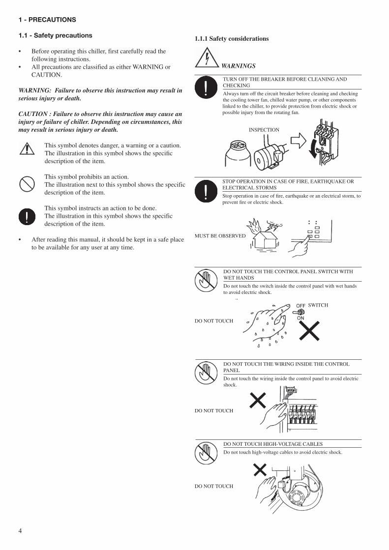
TURN OFF THE BREAKER BEFORE CLEANING AND CHECKING
Always turn off the circuit breaker before cleaning and checking the cooling tower fan, chilled water pump, or other components linked to the chiller, to provide protection from electric shock or possible injury from the rotating fan.
DO NOT TOUCH THE CONTROL PANEL SWITCH WITH WET HANDS
Do not touch the switch inside the control panel with wet hands to avoid electric shock.
STOP OPERATION IN CASE OF FIRE, EARTHQUAKE OR ELECTRICAL STORMS
Stop operation in case of fire, earthquake or an electrical storm, to prevent fire or electric shock.
DO NOT TOUCH THE WIRING INSIDE THE CONTROL PANEL
Do not touch the wiring inside the control panel to avoid electric shock.
SWITCH
DO NOT TOUCH
DO NOT TOUCH
DO NOT TOUCH HIGH-VOLTAGE CABLES
Do not touch high-voltage cables to avoid electric shock.
DO NOT TOUCH
MUST BE OBSERVED
1.1.1 safety considerations
WARNINGS
INSPECTION
�
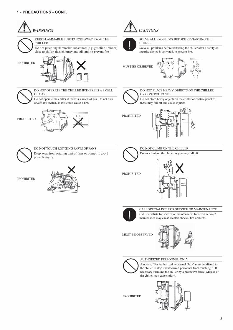
DO NOT OPERATE THE CHILLER IF THERE IS A SMELL OF GAS
Do not operate the chiller if there is a smell of gas. Do not turn on/off any switch, as this could cause a fire.
DO NOT TOUCH ROTATING PARTS OF FANS
Keep away from rotating part of fans or pumps to avoid possible injury.
PROHIBITED
PROHIBITED
PROHIBITED
SOLVE ALL PROBLEMS BEFORE RESTARTING THE CHILLER
Solve all problems before restarting the chiller after a safety or security device is activated, to prevent fire.
MUST BE OBSERVED
DO NOT PLACE HEAVY OBJECTS ON THE CHILLER OR CONTROL PANEL
Do not place heavy objects on the chiller or control panel as these may fall off and cause injuries.
PROHIBITED
DO NOT CLIMB ON THE CHILLER
Do not climb on the chiller as you may fall off.
PROHIBITED
CALL SPECIALISTS FOR SERVICE OR MAINTENANCE
Call specialists for service or maintenance. Incorrect service/ maintenance may cause electric shocks, fire or burns.
MUST BE OBSERVED
AUTHORIZED PERSONNEL ONLY
A notice, "For Authorized Personnel Only" must be affixed to the chiller to stop unauthorized personnel from touching it. If necessary surround the chiller by a protective fence. Misuse of the chiller may cause injury.
PROHIBITED
WARNINGS CAUTIONS
1 - PrecaUTioNs - coNT.
KEEP FLAMMABLE SUBSTANCES AWAY FROM THE CHILLER
Do not place any flammable substances (e.g. gasoline, thinner) close to chiller, flue, chimney and oil tank to prevent fire.
�
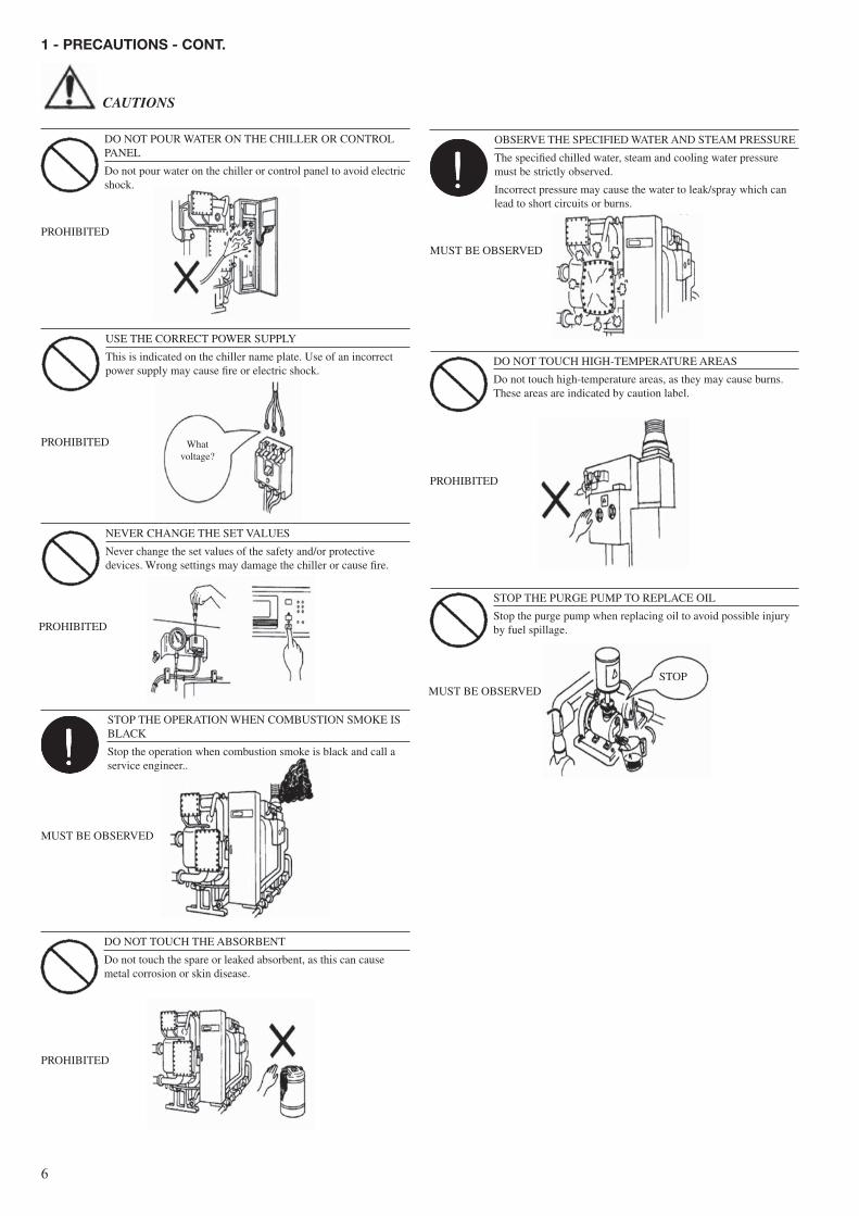
DO NOT POUR WATER ON THE CHILLER OR CONTROL PANEL
Do not pour water on the chiller or control panel to avoid electric shock.
PROHIBITED
USE THE CORRECT POWER SUPPLY
This is indicated on the chiller name plate. Use of an incorrect power supply may cause fire or electric shock.
PROHIBITED
NEVER CHANGE THE SET VALUES
Never change the set values of the safety and/or protective devices. Wrong settings may damage the chiller or cause fire.
PROHIBITED
STOP THE OPERATION WHEN COMBUSTION SMOKE IS BLACK
Stop the operation when combustion smoke is black and call a service engineer..
MUST BE OBSERVED
DO NOT TOUCH THE ABSORBENT
Do not touch the spare or leaked absorbent, as this can cause metal corrosion or skin disease.
PROHIBITED
OBSERVE THE SPECIFIED WATER AND STEAM PRESSURE
The specified chilled water, steam and cooling water pressure must be strictly observed.
Incorrect pressure may cause the water to leak/spray which can lead to short circuits or burns.
MUST BE OBSERVED
PROHIBITED
STOP THE PURGE PUMP TO REPLACE OIL
Stop the purge pump when replacing oil to avoid possible injury by fuel spillage.
MUST BE OBSERVED
DO NOT TOUCH HIGH-TEMPERATURE AREAS
Do not touch high-temperature areas, as they may cause burns. These areas are indicated by caution label.
Whatvoltage?
STOP
CAUTIONS
1 - PrecaUTioNs - coNT.
�
4: Absorption chiller
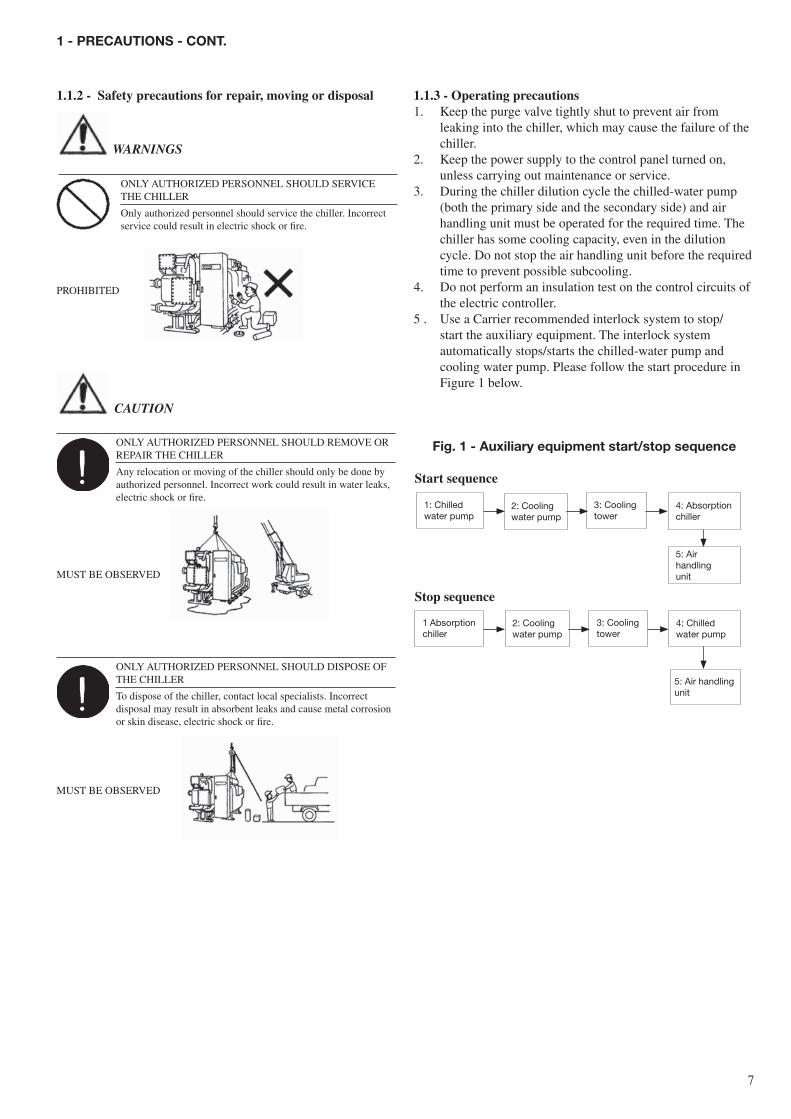
ONLY AUTHORIZED PERSONNEL SHOULD SERVICE THE CHILLER
Only authorized personnel should service the chiller. Incorrect service could result in electric shock or fire.
PROHIBITED
1.1.2 - safety precautions for repair, moving or disposal
ONLY AUTHORIZED PERSONNEL SHOULD REMOVE OR REPAIR THE CHILLER
Any relocation or moving of the chiller should only be done by authorized personnel. Incorrect work could result in water leaks, electric shock or fire.
MUST BE OBSERVED
ONLY AUTHORIZED PERSONNEL SHOULD DISPOSE OF THE CHILLER
To dispose of the chiller, contact local specialists. Incorrect disposal may result in absorbent leaks and cause metal corrosion or skin disease, electric shock or fire.
MUST BE OBSERVED
WARNINGS
CAUTION
1.1.3 - Operating precautions1. Keep the purge valve tightly shut to prevent air from
leaking into the chiller, which may cause the failure of the chiller.
2. Keep the power supply to the control panel turned on, unless carrying out maintenance or service.
3. During the chiller dilution cycle the chilled-water pump (both the primary side and the secondary side) and air handling unit must be operated for the required time. The chiller has some cooling capacity, even in the dilution cycle. Do not stop the air handling unit before the required time to prevent possible subcooling.
4. Do not perform an insulation test on the control circuits of the electric controller.
5 . Use a Carrier recommended interlock system to stop/start the auxiliary equipment. The interlock system automatically stops/starts the chilled-water pump and cooling water pump. Please follow the start procedure in Figure 1 below.
Fig. 1 - auxiliary equipment start/stop sequence
start sequence
1: Chilled water pump
2: Cooling water pump
3: Cooling tower
5: Air handling unit
1 Absorption chiller
2: Cooling water pump
3: Cooling tower
4: Chilled water pump
5: Air handling unit
1 - PrecaUTioNs - coNT.
stop sequence
�
2 - MacHiNe illUsTraTioNs
2.1 - Typical chiller detail
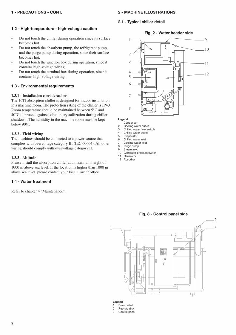
Fig. 2 - Water header side
1
2
3
4 5
6
7
8
9
10
11
12
Fig. 3 - control panel side2
3
legend1 Condenser2 Cooling water outlet3 Chilled water flow switch4 Chilled water outlet5 Evaporator6 Chilled water inlet7 Cooling water inlet8 Purge pump9 Steam inlet10 Generator pressure switch11 Generator12 Absorber
1
legend1 Drain outlet2 Rupture disk3 Control panel
1 - PrecaUTioNs - coNT.
1.2 - High-temperature - high-voltage caution
• Do not touch the chiller during operation since its surface becomes hot.
• Do not touch the absorbent pump, the refrigerant pump, and the purge pump during operation, since their surface becomes hot.
• Do not touch the junction box during operation, since it contains high-voltage wiring.
• Do not touch the terminal box during operation, since it contains high-voltage wiring.
1.3 - environmental requirements
1.3.1 - installation considerationsThe 16TJ absorption chiller is designed for indoor installation in a machine room. The protection rating of the chiller is IP40. Room temperature should be maintained between 5°C and 40°C to protect against solution crystallization during chiller shutdown. The humidity in the machine room must be kept below 90%.
1.3.2 - Field wiringThe machines should be connected to a power source that complies with overvoltage category III (IEC 60664). All other wiring should comply with overvoltage category II.
1.3.3 - altitudePlease install the absorption chiller at a maximum height of 1000 m above sea level. If the location is higher than 1000 m above sea level, please contact your local Carrier office.
1.4 - Water treatment
Refer to chapter 4 "Maintenance”.

�
2.2 - Typical control panel
Fig. 4 - control panel (ce type)
1
6
2
7
3
8
9
4
5
legend1 Fan2 Terminal block3 Terminal block4 Terminal block for power supply5 Earth terminal6 Control board7 Purge indication light8 Purge pump on/off switch9 Operating handle
Fig. 5 - control panel inside (ce type)
1
9
2
3
10
4
5
6
7
8legend1 Control relay2 Circuit protector3 I/O board4 Circuit breaker5 Main circuit breaker6 Transformer7 Electromagnetic contactor8 Filter9 Transformer10 Terminal block
10
STOP RUN
CHILLER
REF PUMP
PURGE PUMP
ABS PUMP
STAND BY
DILUTION
SAFETY CIRCUIT
CHILLER ALARM
POWER
STOP RUN
OPERATION
BUZZER STOP LOCAL
REMOTE
SET BACK
1
2
3
4
5
6
7
8
9
10
11
12
13
14
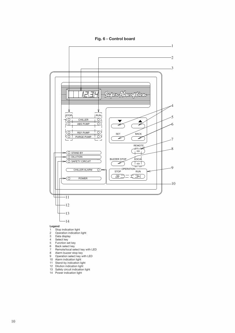
Fig. 6 - control board
legend1 Stop indication light2 Operation indication light3 Data display4 Select key5 Function set key6 Back select key7 Remote/local select key with LED8 Alarm buzzer stop key9 Operation select key with LED10 Alarm indication light11 Stand-by indication light12 Dilution indication light13 Safety circuit indication light14 Power indication light
11
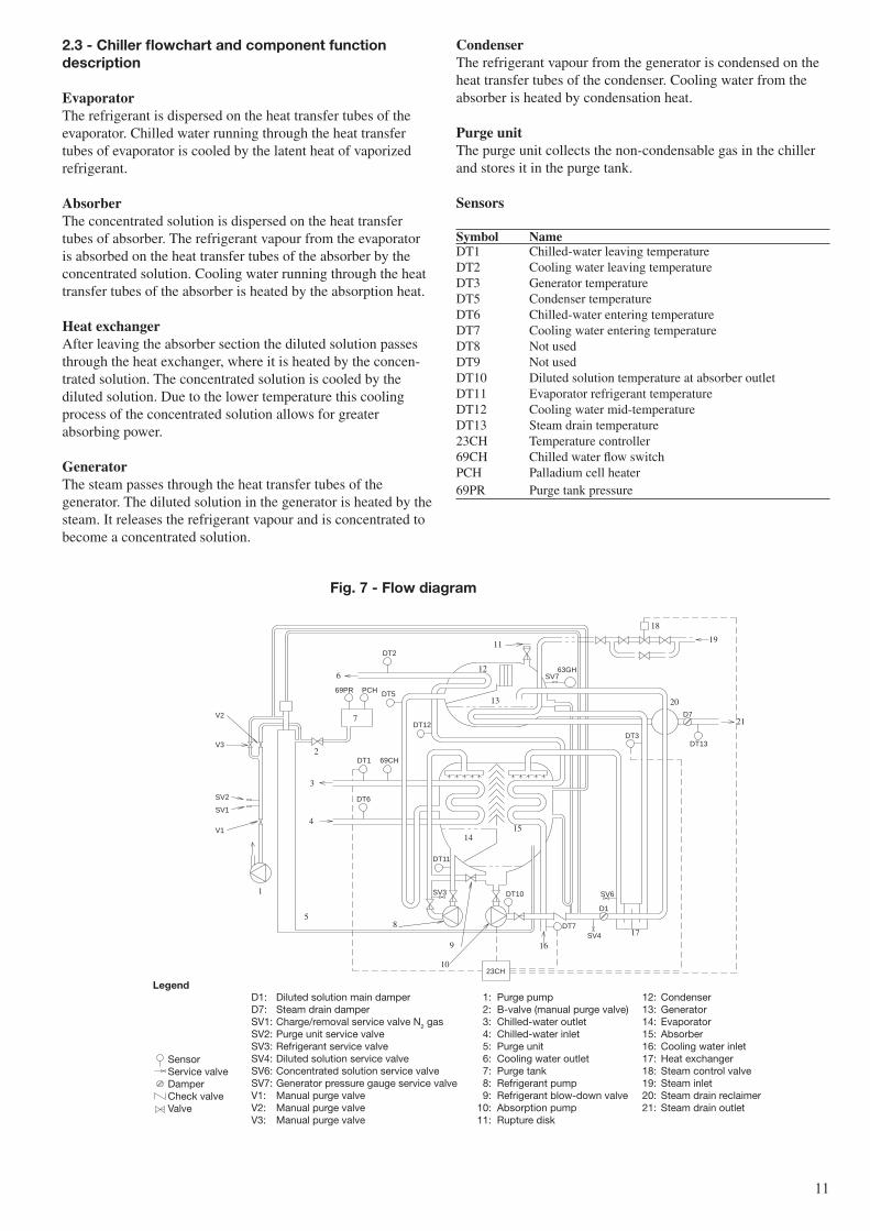
2.3 - chiller flowchart and component function description
evaporatorThe refrigerant is dispersed on the heat transfer tubes of the evaporator. Chilled water running through the heat transfer tubes of evaporator is cooled by the latent heat of vaporized refrigerant.
absorberThe concentrated solution is dispersed on the heat transfer tubes of absorber. The refrigerant vapour from the evaporator is absorbed on the heat transfer tubes of the absorber by the concentrated solution. Cooling water running through the heat transfer tubes of the absorber is heated by the absorption heat.
Heat exchangerAfter leaving the absorber section the diluted solution passes through the heat exchanger, where it is heated by the concen-trated solution. The concentrated solution is cooled by the diluted solution. Due to the lower temperature this cooling process of the concentrated solution allows for greater absorbing power.
generatorThe steam passes through the heat transfer tubes of the generator. The diluted solution in the generator is heated by the steam. It releases the refrigerant vapour and is concentrated to become a concentrated solution.
Fig. 7 - Flow diagram
V2
V3
SV2
SV1
V1
DT10
DT6
69CHDT1
DT5
DT2
PCH69PR
DT12
DT13
D7
DT7
SV6
D1
SV4
SV763GH
DT3
SV3
DT11
23CH
D1: Diluted solution main damper 1: Purge pump 12: CondenserD7: Steam drain damper 2: B-valve (manual purge valve) 13: GeneratorSV1: Charge/removal service valve N2 gas 3: Chilled-water outlet 14: EvaporatorSV2: Purge unit service valve 4: Chilled-water inlet 15: AbsorberSV3: Refrigerant service valve 5: Purge unit 16: Cooling water inletSV4: Diluted solution service valve 6: Cooling water outlet 17: Heat exchangerSV6: Concentrated solution service valve 7: Purge tank 18: Steam control valveSV7: Generator pressure gauge service valve 8: Refrigerant pump 19: Steam inletV1: Manual purge valve 9: Refrigerant blow-down valve 20: Steam drain reclaimerV2: Manual purge valve 10: Absorption pump 21: Steam drain outletV3: Manual purge valve 11: Rupture disk
SensorService valveDamperCheck valveValve
legend
1
58
4
3
2
6
7
9
10
11
13
12
1415
16
17
21
19
18
20
CondenserThe refrigerant vapour from the generator is condensed on the heat transfer tubes of the condenser. Cooling water from the absorber is heated by condensation heat.
Purge unitThe purge unit collects the non-condensable gas in the chiller and stores it in the purge tank.
sensors symbol nameDT1 Chilled-water leaving temperatureDT2 Cooling water leaving temperatureDT3 Generator temperatureDT5 Condenser temperatureDT6 Chilled-water entering temperatureDT7 Cooling water entering temperatureDT8 Not usedDT9 Not usedDT10 Diluted solution temperature at absorber outletDT11 Evaporator refrigerant temperatureDT12 Cooling water mid-temperatureDT13 Steam drain temperature23CH Temperature controller69CH Chilled water flow switchPCH Palladium cell heater69PR Purge tank pressure
1�
3 - oPeraTiNg iNsTrUcTioNs
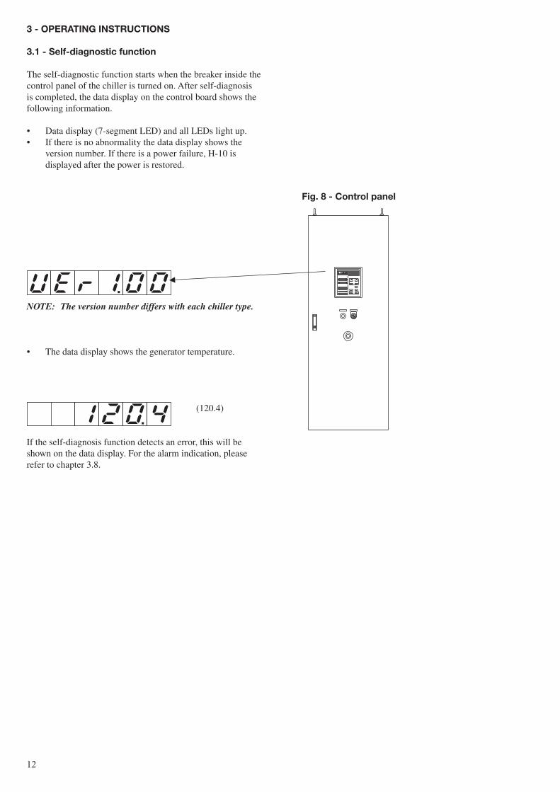
3.1 - self-diagnostic function
The self-diagnostic function starts when the breaker inside the control panel of the chiller is turned on. After self-diagnosis is completed, the data display on the control board shows the following information.
• Data display (7-segment LED) and all LEDs light up.• If there is no abnormality the data display shows the
version number. If there is a power failure, H-10 is displayed after the power is restored.
NOTe: The version number differs with each chiller type.
• The data display shows the generator temperature.
(120.4)
If the self-diagnosis function detects an error, this will be shown on the data display. For the alarm indication, please refer to chapter 3.8.
Fig. 8 - control panel
1�
STOP RUN
CHILLER
REF PUMP
PURGE PUMP
ABS PUMP
STAND BY
DILUTION
SAFETY CIRCUIT
CHILLER ALARM
POWER
STOP RUN
OPERATION
BUZZER STOP LOCAL
REMOTE
SET BACK
1
2
4
6
7
8
9
10
12
5
11
3
Fig. 9 - Typical control board
legend
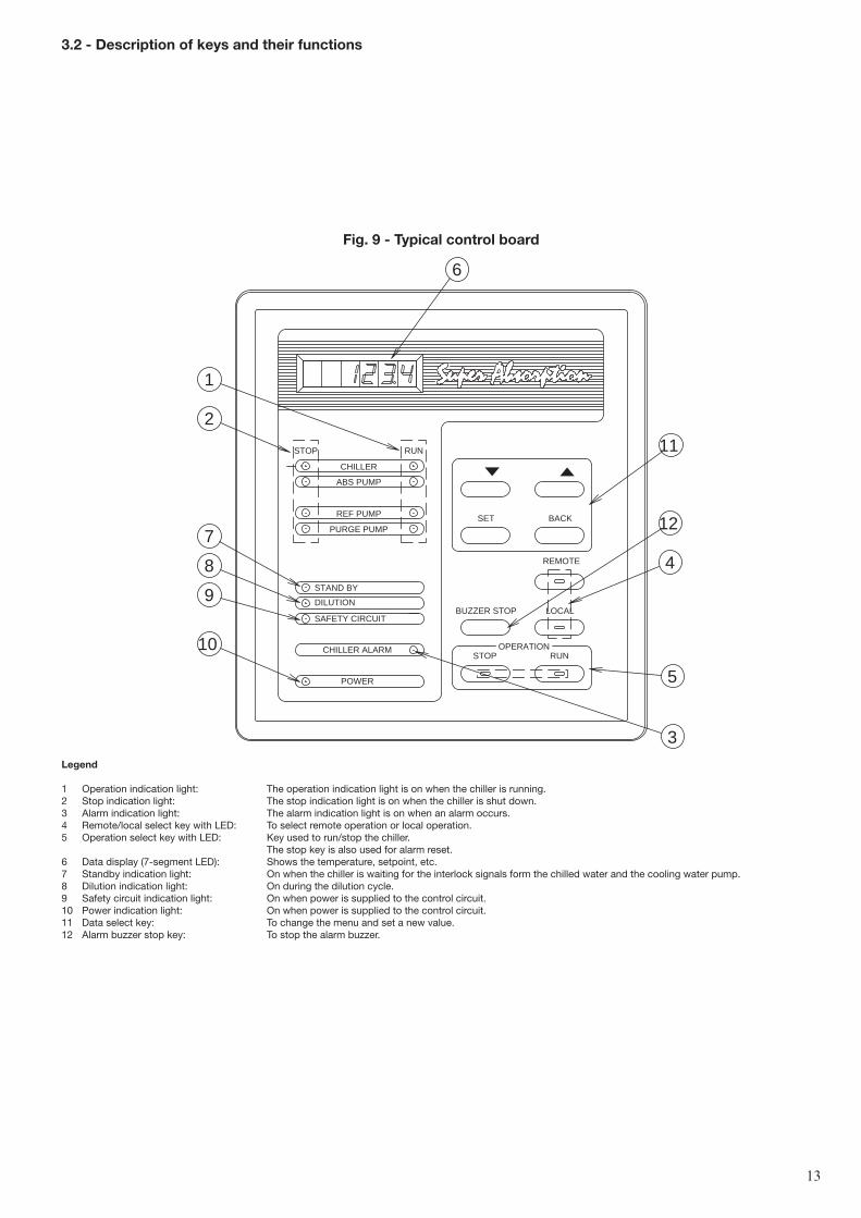
1 Operation indication light: The operation indication light is on when the chiller is running.2 Stop indication light: The stop indication light is on when the chiller is shut down.3 Alarm indication light: The alarm indication light is on when an alarm occurs.4 Remote/local select key with LED: To select remote operation or local operation.5 Operation select key with LED: Key used to run/stop the chiller. The stop key is also used for alarm reset.6 Data display (7-segment LED): Shows the temperature, setpoint, etc.7 Standby indication light: On when the chiller is waiting for the interlock signals form the chilled water and the cooling water pump.8 Dilution indication light: On during the dilution cycle.9 Safety circuit indication light: On when power is supplied to the control circuit.10 Power indication light: On when power is supplied to the control circuit.11 Data select key: To change the menu and set a new value.12 Alarm buzzer stop key: To stop the alarm buzzer.
3.2 - Description of keys and their functions
1�
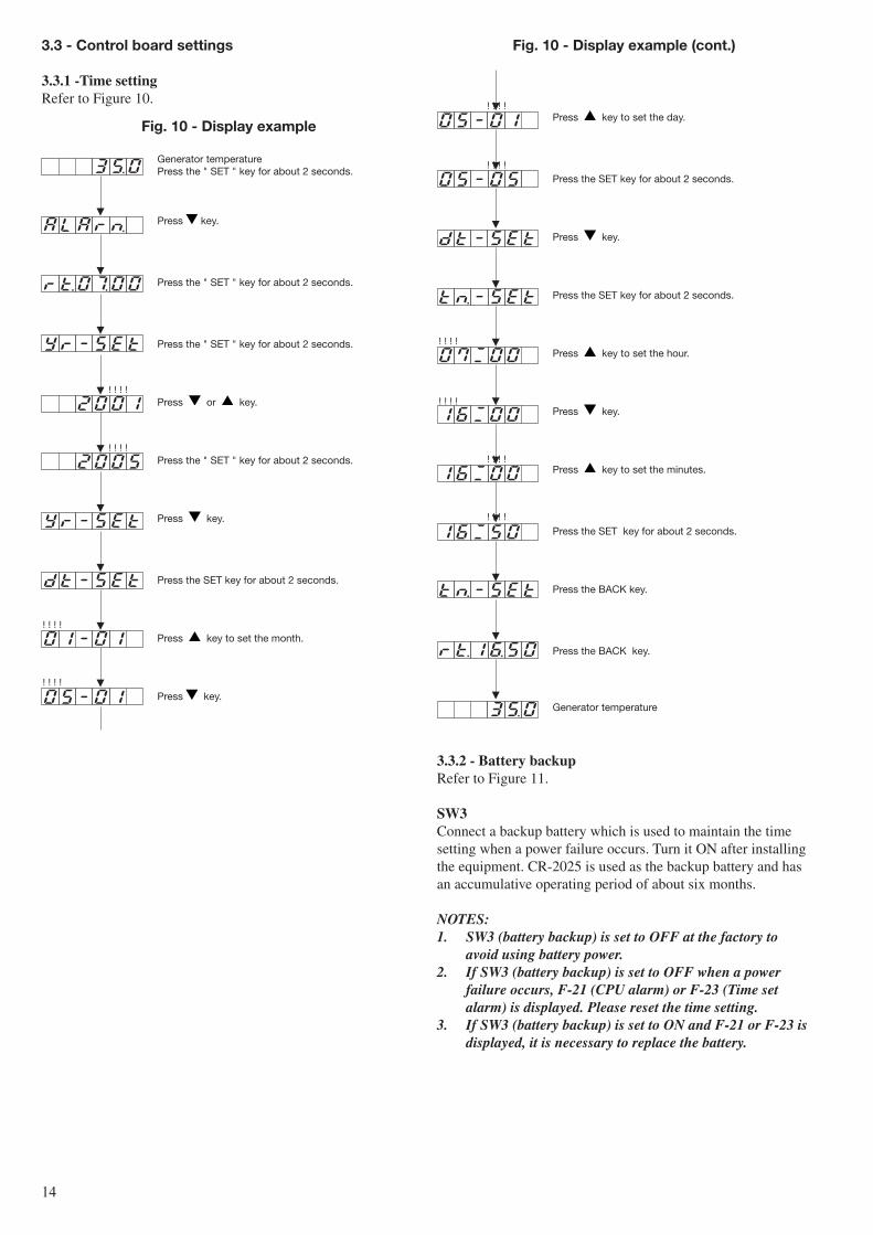
3.3 - control board settings
3.3.1 -Time settingRefer to Figure 10.
! ! ! !
! ! ! !
! ! ! !
! ! ! !
Fig. 10 - Display example
Generator temperaturePress the " SET " key for about 2 seconds.
Press key.
Press the " SET " key for about 2 seconds.
Press the " SET " key for about 2 seconds.
Press or key.
Press the " SET " key for about 2 seconds.
Press key.
Press the SET key for about 2 seconds.
Press key to set the month.
Press key.
! ! ! !
! ! ! !
! ! ! !
! ! ! !
! ! ! !
! ! ! !
Fig. 10 - Display example (cont.)
Press key to set the day.
Press the SET key for about 2 seconds.
Press key.
Press the SET key for about 2 seconds.
Press key to set the hour.
Press key.
Press key to set the minutes.
Press the SET key for about 2 seconds.
Press the BACK key.
Press the BACK key.
Generator temperature
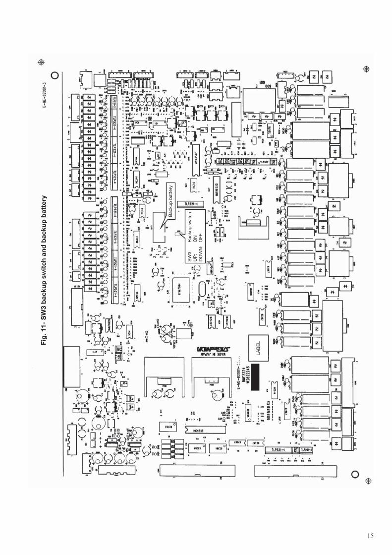
3.3.2 - battery backupRefer to Figure 11.
sW3Connect a backup battery which is used to maintain the time setting when a power failure occurs. Turn it ON after installing the equipment. CR-2025 is used as the backup battery and has an accumulative operating period of about six months.
NOTeS:1. SW3 (battery backup) is set to OFF at the factory to
avoid using battery power.2. If SW3 (battery backup) is set to OFF when a power
failure occurs, F-21 (CPU alarm) or F-23 (Time set alarm) is displayed. Please reset the time setting.
3. If SW3 (battery backup) is set to ON and F-21 or F-23 is displayed, it is necessary to replace the battery.
1�
Fig
. 11-
sW
3 b
acku
p s
wit
ch a
nd b
acku
p b
atte
ry
Bac
kup
bat
tery
SW
3:
Bac
kup
sw
itch
UP
: O
ND
OW
N:
OFF
LAB
EL
1�
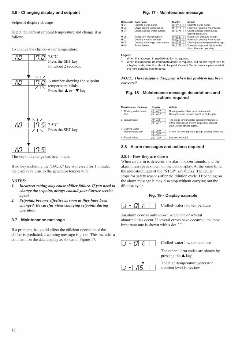
Fig. 13 - Display example
Generator temperature Press the SET key for about 2 seconds.
Press the or key.
Press the SET key for about 2 seconds.
Press the or key.
Press the or key.
Press the SET key for about 2 seconds.Then press the or key.
To select the pulse mode
By pressing the SET key, the pulse mode is selected.
Press the SET key for about 2 seconds.Then press the or key.
To select the negative mode
Press SET" key to select negative mode.
To select the static mode
By pressing the SET key, the static mode is selected.
To select the positive mode
Press SET key to select positive mode.
STOP RUN
CHILLER
REF PUMP
PURGE PUMP
ABS PUMP
STAND BY
DILUTION
SAFETY CIRCUIT
CHILLER ALARM
POWER
STOP RUN
OPERATION
BUZZER STOP LOCAL
REMOTE
SET BACK
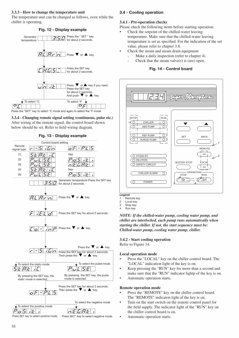
Fig. 14 - control board
1
2
3 4
legend1 Remote key2 Local key3 Stop key4 Run key
Control board setting Remote signal type
(1) free
(2)
(3)
(4) free
(5)
NOTe: If the chilled-water pump, cooling water pump, and chiller are interlocked, each pump runs automatically when starting the chiller. If not, the start sequence must be:Chilled-water pump, cooling water pump, chiller.
3.4.2 - start cooling operationRefer to Figure 14.
local operation mode• Press the "LOCAL" key on the chiller control board. The
"LOCAL" indication light of the key is on.• Keep pressing the "RUN" key for more than a second and
make sure that the "RUN" indicator lightp of the key is on.• Automatic operation starts.
remote operation mode• Press the "REMOTE" key on the chiller control board.
The "REMOTE" indicaton light of the key is on.• Turn on the start switch on the remote control panel for
the field supply. The indicator light of the "RUN" key on the chiller control board is on.
• Automatic operation starts.
3.4 - cooling operation
3.4.1 - Pre-operation checksPlease check the following items before starting operation:• Check the setpoint of the chilled-water leaving
temperature. Make sure that the chilled-water leaving temperature is set as specified. For the indication of the set value, please refer to chapter 3.8.
• Check the steam and steam drain equipment - Make a daily inspection (refer to chapter 4). - Check that the steam valve(s) is (are) open.
3.3.4 - Changing remote signal setting (continuous, pulse etc.) After wiring of the remote signal, the control board shown below should be set. Refer to field wiring diagram.
3.3.3 - How to change the temperature unitThe temperature unit can be changed as follows, even while the chiller is operating.
Fig. 12 - Display example
Press the " SET " key for about 2 seconds.
Press or key.
Press the SET key for about 2 seconds.
Press or key if you need.Press the SET key for about 2 seconds.And push or key.
To select °C To select °F
Press the "SET" key to select °C mode and again to select the °F mode
Generator temperature
1�
It returns to the generator temperature display when no key is pressed for 1 minute.
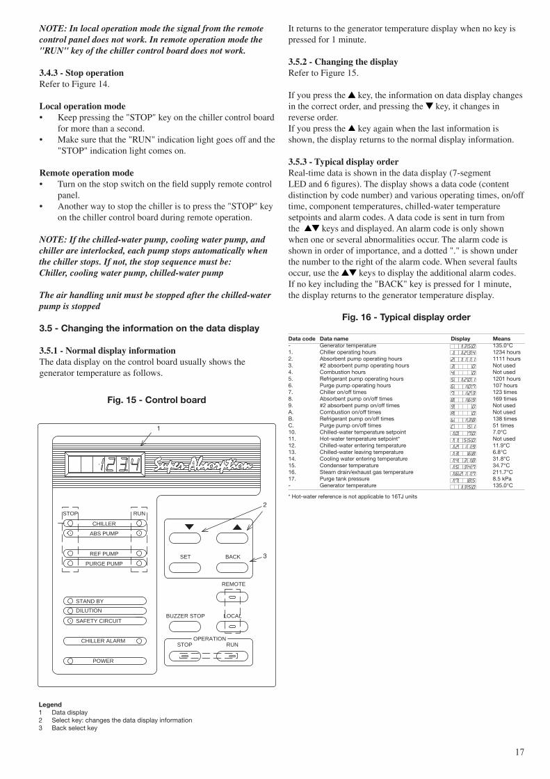
3.5.2 - Changing the displayRefer to Figure 15.
If you press the key, the information on data display changes in the correct order, and pressing the key, it changes in reverse order.If you press the key again when the last information is shown, the display returns to the normal display information.
3.5.3 - Typical display orderReal-time data is shown in the data display (7-segment LED and 6 figures). The display shows a data code (content distinction by code number) and various operating times, on/off time, component temperatures, chilled-water temperature setpoints and alarm codes. A data code is sent in turn from the keys and displayed. An alarm code is only shown when one or several abnormalities occur. The alarm code is shown in order of importance, and a dotted "." is shown under the number to the right of the alarm code. When several faults occur, use the keys to display the additional alarm codes. If no key including the "BACK" key is pressed for 1 minute, the display returns to the generator temperature display.
Fig. 16 - Typical display order
Data code Data name Display Means- Generator temperature 135.0°C1. Chiller operating hours 1234 hours2. Absorbent pump operating hours 1111 hours3. #2 absorbent pump operating hours Not used4. Combustion hours Not used5. Refrigerant pump operating hours 1201 hours6. Purge pump operating hours 107 hours7. Chiller on/off times 123 times8. Absorbent pump on/off times 169 times9. #2 absorbent pump on/off times Not usedA. Combustion on/off times Not usedB. Refrigerant pump on/off times 138 timesC. Purge pump on/off times 51 times10. Chilled-water temperature setpoint 7.0°C11. Hot-water temperature setpoint* Not used12. Chilled-water entering temperature 11.9°C13. Chilled-water leaving temperature 6.8°C14. Cooling water entering temperature 31.8°C15. Condenser temperature 34.7°C16. Steam drain/exhaust gas temperature 211.7°C17. Purge tank pressure 8.5 kPa- Generator temperature 135.0°C
* Hot-water reference is not applicable to 16TJ units
STOP RUN
CHILLER
REF PUMP
PURGE PUMP
ABS PUMP
STAND BY
DILUTION
SAFETY CIRCUIT
CHILLER ALARM
POWER
STOP RUN
OPERATION
BUZZER STOP LOCAL
REMOTE
SET BACK
Fig. 15 - control board
legend1 Data display2 Select key: changes the data display information3 Back select key
2
3
1
NOTe: In local operation mode the signal from the remote control panel does not work. In remote operation mode the "RUN" key of the chiller control board does not work.
3.4.3 - stop operationRefer to Figure 14.
local operation mode• Keep pressing the "STOP" key on the chiller control board
for more than a second.• Make sure that the "RUN" indication light goes off and the
"STOP" indication light comes on.
remote operation mode• Turn on the stop switch on the field supply remote control
panel.• Another way to stop the chiller is to press the "STOP" key
on the chiller control board during remote operation.
NOTe: If the chilled-water pump, cooling water pump, and chiller are interlocked, each pump stops automatically when the chiller stops. If not, the stop sequence must be:Chiller, cooling water pump, chilled-water pump
The air handling unit must be stopped after the chilled-water pump is stopped
3.5 - changing the information on the data display
3.5.1 - normal display informationThe data display on the control board usually shows the generator temperature as follows.
1�
3.6 - changing display and setpoint
setpoint display change
Select the current setpoint temperature and change it as follows.
To change the chilled-water temperature:
7.0°C Press the SET key for about 2 seconds.
A number showing the setpoint temperature blinks. Press the or key.
7.5°C Press the SET key
The setpoint change has been made.
If no key including the "BACK" key is pressed for 1 minute, the display returns to the generator temperature.
NOTeS:1. Incorrect setting may cause chiller failure. If you need to
change the setpoint, always consult your Carrier service agent.
2. Setpoints become effective as soon as they have been changed. Be careful when changing setpoints during operation.
3.7 - Maintenance message
If a problem that could affect the efficient operation of the chiller is predicted, a warning message is given. This includes a comment on the data display as shown in Figure 17.
Fig. 17 - Maintenance message
Data code Data name Display MeansH-01* Operate purge pump Operate purge pump.H-03* Clean cooling water tubes Fouling of cooling water tubes.H-04* Check cooling water system Check cooling water pump, cooling tower, etc.H-06** Purge tank high pressure Purge tank pressure is high.H-07** Cooling water tubes foul Fouling of cooling water tubes.H-08** Cooling water high temperature Cooling water temperature is high.H-10 Power failure There was a power failure while the chiller was operating
legend* When this appears, immediate action is required.** When this appears, no immediate action is required, but as this might lead to
a higher code, attention should be paid. Consult Carrier service personnel at the next periodic maintenance.
NOTe: These displays disappear when the problem has been corrected.
Fig. 18 - Maintenance message descriptions and actions required
Maintenance message Display action
1 Cooling water tubes Cooling water tubes must be cleaned. foul Contact Carrier service agent to do the job
2 Vacuum rate The purge tank must be purged immediately. If this message is shown frequently, contact your Carrier service agent. 3 Cooling water high temperature Check the cooling water pump, cooling tower, etc.
4 Power failure See section 3.8.5.
3.8 - alarm messages and actions required
3.8.1 - How they are shownWhen an alarm is detected, the alarm buzzer sounds, and the alarm message is shown on the data display. At the same time, the indication light of the "STOP" key blinks. The chiller stops for safety reasons after the dilution cycle. Depending on the alarm message it may also stop without carrying out the dilution cycle.
Fig. 19 - Display example
Chilled-water low temperature
An alarm code is only shown when one or several abnormalities occur. If several errors have occurred, the most important one is shown with a dot ".".
Chilled-water low temperature
The other alarm codes are shown by pressing the key.
The high-temperature generator solution level is too low.
Maintenance Message Display Action
1 Fouling of cooling
water tubes Cooling water tubes must be cleaned.
Contact Carrier/SANYO service agent to do the job.
2 Vacuum rate
The purge tank must be purged immediately.
In case this indication is shown frequently,contact Carrier/SANYO service agent.
3 High temperature
of cooling water Check the cooling water pump, cooling tower, etc.
4 Power failure See section 3-8-5.
1�
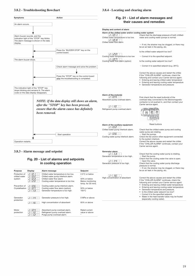
3.8.4 - locating and clearing alarm
Fig. 21 - list of alarm messages and their causes and remedies
Display and content of alarm
alarm of the chilled water and/or cooling water system Check that the discharge pressure of both chillled-Chilled water temperature is too low. water and cooling water pumps is normal.
Chilled water flow alarm → If not, the strainer may be clogged, or there may be an air leak in the piping, etc. Is the chilled-water setpoint too low? Cooling water temperature is too low → Correct it to the specified setpoint. Cooling water flow alarm (option) Is the cooling water setpoint too low? → Correct it to specified setpoint (e.g. 28°C). Correct the above causes and restart the chiller. If the "CHILLER ALARM" continues, check the following and contact your Carrier service agent: • Entering and leaving chilled-water temperature • Entering and leaving cooling water temperature • Generator temperature and pressure
alarm of the motor(s) First check that the reset button(s) of theAbsorbent pump overload alarm. overload relay connected to the electromagnetic contactor is not pushed in, and then contact your Carrier service agent. Refrigerant pump overload alarm
Reset buttonsalarm of the auxiliary equipment Chilled water pump interlock alarm. Check that the chilled-water pump and cooling water pump are rotating. → Start the pumpsCooling water pump interlock alarm. Check the fan and/or other equipment connected to the system interlock. Correct the above causes and restart the chiller. If the "CHILLER ALARM" continues, contact your Carrier service agent.
generator alarm Check that the cooling water pump is rotating.Generator temperature is too high. → Start the pump. Check that the cooling water line valve is open. → Open the valve.Generator pressure is too high. Check that the cooling water pump discharge pressure is normal. → If not, the strainer may be clogged, or there may be an air leak in the piping, etc.
High concentration of absorbent Correct the above causes and restart the chiller If the "CHILLER ALARM" continues, check the following and contact your Carrier service agent: • Entering and leaving chilled-water temperature • Entering and leaving cooling water temperature • Generator temperature and pressure. • Is the chilled water setpoint too low? → Correct it to the specified setpoint. • Water in the heat transfer tubes may be fouled (especially cooling water).
3.8.2 - Troubleshooting flowchart
symptoms action
An alarm occurs.
Alarm buzzer sounds, and the indication light of the "STOP" key blinks. The alarm message is shown in the data display.
Press the "BUZZER STOP" key on the control board.
The alarm buzzer stops.
Check alarm message and solve the problem.
Press the "STOP" key on the control board after the troubleshooting is completed.
The indication light of the "STOP" key stops blinking and remains lit. The alarm code on the data display disappears.
NOTe: If the data display still shows an alarm, after the "STOP" key has been pressed, ensure that the alarm cause has definitely been removed.
Start operation
Operation restarts.
3.8.3 - alarm message and setpoint
Fig. 20 - list of alarms and setpoints in cooling operation
Purpose Display alarm message setpoint
Protection of Chilled water temperature is too low. 2.5°C or belowchilled water Chilled water pump interlock alarm. -system Chilled water flow alarm 50% or below Cooling water temperature is too low. Below monitoring temp. for 30 mins.Prevention of Cooling water pump interlock alarm. -Crystallisation Cooling water flow alarm (option) 50% or below Generator temperature is too high. 105°C
Generator Generator pressure is too high. 0 MPa or aboveprotection High concentration of absorbent 65% or above
Motor Absorbent pump overload alarm. Rated currentprotection Refrigerant pump overload alarm. value or above Purge pump overload alarm. "
�0
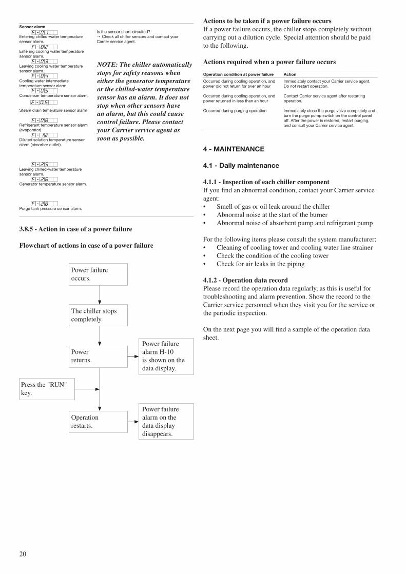
sensor alarm Is the sensor short-circuited?Entering chilled-water temperature → Check all chiller sensors and contact yoursensor alarm. Carrier service agent. Entering cooling water temperature sensor alarm. Leaving cooling water temperature sensor alarm. Cooling water intermediate temperature sensor alarm. Condenser temperature sensor alarm. Steam drain temerature sensor alarm Refrigerant temperature sensor alarm (evaporator). Diluted solution temperature sensor alarm (absorber outlet). Leaving chilled-water temperature sensor alarm. Generator temperature sensor alarm. Purge tank pressure sensor alarm.
3.8.5 - action in case of a power failure
Flowchart of actions in case of a power failure
Power failure occurs.
The chiller stops completely.
Power failure Power alarm H-10 returns. is shown on the data display.
Press the "RUN" key.
Power failure Operation alarm on the restarts. data display disappears.
actions to be taken if a power failure occursIf a power failure occurs, the chiller stops completely without carrying out a dilution cycle. Special attention should be paid to the following.
actions required when a power failure occurs
operation condition at power failure action
Occurred during cooling operation, and Immediately contact your Carrier service agent.power did not return for over an hour Do not restart operation.
Occurred during cooling operation, and Contact Carrier service agent after restartingpower returned in less than an hour operation.
Occurred during purging operation Immediately close the purge valve completely and turn the purge pump switch on the control panel off. After the power is restored, restart purging, and consult your Carrier service agent.
4 - MaiNTeNaNce
4.1 - Daily maintenance
4.1.1 - inspection of each chiller componentIf you find an abnormal condition, contact your Carrier service agent:• Smell of gas or oil leak around the chiller• Abnormal noise at the start of the burner• Abnormal noise of absorbent pump and refrigerant pump
For the following items please consult the system manufacturer:• Cleaning of cooling tower and cooling water line strainer• Check the condition of the cooling tower• Check for air leaks in the piping
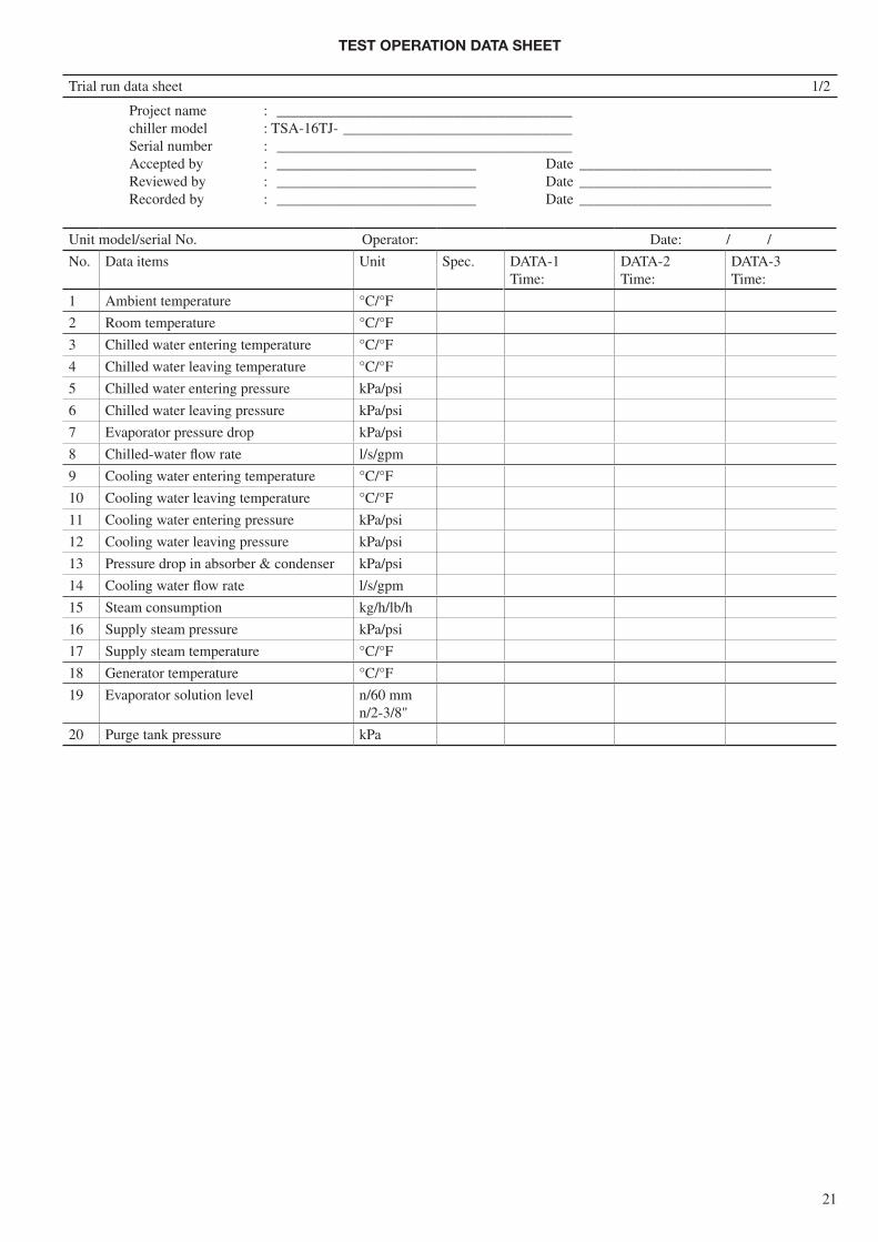
4.1.2 - Operation data recordPlease record the operation data regularly, as this is useful for troubleshooting and alarm prevention. Show the record to the Carrier service personnel when they visit you for the service or the periodic inspection.
On the next page you will find a sample of the operation data sheet.
NOTe: The chiller automatically stops for safety reasons when either the generator temperature or the chilled-water temperature sensor has an alarm. It does not stop when other sensors have an alarm, but this could cause control failure. Please contact your Carrier service agent as soon as possible.
�1
TesT oPeraTioN DaTa sHeeT
Trial run data sheet 1/2
Project name : ________________________________________chiller model : TSA-16TJ- _______________________________Serial number : ________________________________________Accepted by : ___________________________ Date __________________________Reviewed by : ___________________________ Date __________________________Recorded by : ___________________________ Date __________________________
Unit model/serial No. Operator: Date: / /
No. Data items Unit Spec. DATA-1Time:
DATA-2Time:
DATA-3Time:
1 Ambient temperature °C/°F
2 Room temperature °C/°F
3 Chilled water entering temperature °C/°F
4 Chilled water leaving temperature °C/°F
5 Chilled water entering pressure kPa/psi
6 Chilled water leaving pressure kPa/psi
7 Evaporator pressure drop kPa/psi
8 Chilled-water flow rate l/s/gpm
9 Cooling water entering temperature °C/°F
10 Cooling water leaving temperature °C/°F
11 Cooling water entering pressure kPa/psi
12 Cooling water leaving pressure kPa/psi
13 Pressure drop in absorber & condenser kPa/psi
14 Cooling water flow rate l/s/gpm
15 Steam consumption kg/h/lb/h
16 Supply steam pressure kPa/psi
17 Supply steam temperature °C/°F
18 Generator temperature °C/°F
19 Evaporator solution level n/60 mmn/2-3/8"
20 Purge tank pressure kPa
��
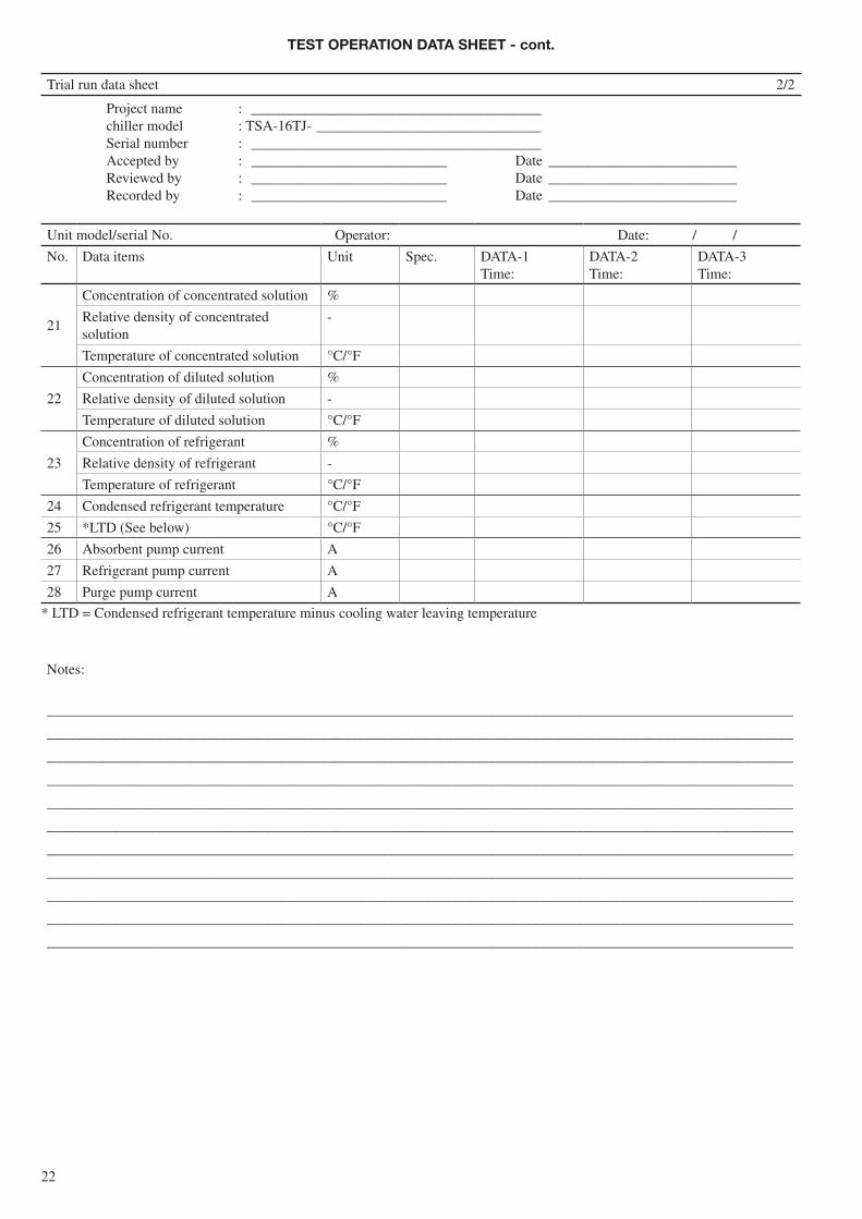
TesT oPeraTioN DaTa sHeeT - cont.
Trial run data sheet 2/2
Project name : ________________________________________chiller model : TSA-16TJ- _______________________________Serial number : ________________________________________Accepted by : ___________________________ Date __________________________Reviewed by : ___________________________ Date __________________________Recorded by : ___________________________ Date __________________________
Unit model/serial No. Operator: Date: / /
No. Data items Unit Spec. DATA-1Time:
DATA-2Time:
DATA-3Time:
21
Concentration of concentrated solution %
Relative density of concentrated solution
-
Temperature of concentrated solution °C/°F
22
Concentration of diluted solution %
Relative density of diluted solution -
Temperature of diluted solution °C/°F
23
Concentration of refrigerant %
Relative density of refrigerant -
Temperature of refrigerant °C/°F
24 Condensed refrigerant temperature °C/°F
25 *LTD (See below) °C/°F
26 Absorbent pump current A
27 Refrigerant pump current A
28 Purge pump current A
* LTD = Condensed refrigerant temperature minus cooling water leaving temperature
Notes:
_______________________________________________________________________________________________________
_______________________________________________________________________________________________________
_______________________________________________________________________________________________________
_______________________________________________________________________________________________________
_______________________________________________________________________________________________________
_______________________________________________________________________________________________________
_______________________________________________________________________________________________________
_______________________________________________________________________________________________________
_______________________________________________________________________________________________________
_______________________________________________________________________________________________________
_______________________________________________________________________________________________________
��
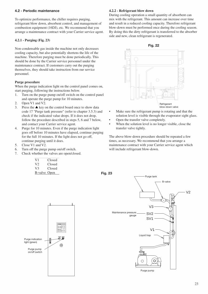
4.2.2 - refrigerant blow downDuring cooling operation a small quantity of absorbent can mix with the refrigerant. This amount can increase over time and result in a reduced cooling capacity. Therefore refrigerant blow-down must be performed once during the cooling season. By doing this the dirty refrigerant is transferred to the absorber side and new, clean refrigerant is regenerated.
• Make sure the refrigerant pump is rotating and that the solution level is visible through the evaporator sight glass.
• Open the transfer valve completely.• When the solution level is no longer visible, close the
transfer valve tightly.
The above blow-down procedure should be repeated a few times, as necessary. We recommend that you arrange a maintenance contract with your Carrier service agent which will include refrigerant blow-down.
V1
V3
V2
SV2SV1
4.2 - Periodic maintenance
To optimize performance, the chiller requires purging, refrigerant blow down, absorbent control, and management of combustion equipment (16DJ), etc. We recommend that you arrange a maintenance contract with your Carrier service agent.
4.2.1 - Purging (Fig. 23)
Non-condensable gas inside the machine not only decreases cooling capacity, but also potentially shortens the life of the machine. Therefore purging must be done periodically. This should be done by the Carrier service personnel under the maintenance contract. If customers carry out the purging themselves, they should take instruction from our service personnel.
Purge procedureWhen the purge indication light on the control panel comes on, start purging, following the instructions below.1. Turn on the purge pump on/off switch on the control panel
and operate the purge pump for 10 minutes.2. Open V1 and V2.3. Press the key on the control board once to show data
code 17 "Purge tank pressure" (refer to chapter 3.5.3) and check if the indicated value drops. If it does not drop, follow the procedure described in steps 5, 6 and 7 below, and contact your Carrier service agent.
4. Purge for 10 minutes. Even if the purge indication light goes off before 10 minutes have elapsed, continue purging for the full 10 minutes. If the light does not go off, continue purging until it does.
5. Close V1 and V2.6. Turn off the purge pump on/off switch.7. Check whether the valves are open/closed.
V1 ClosedV2 ClosedV3 ClosedB-valve Open
Maintenance pressuregauge
Liquid trap
Purge pump
Purge tank
B-valve
Purge indicationlight (green)
Purge pumpon/off switch
Fig. 23
Fig. 22
Refrigerantblow-down valve
��
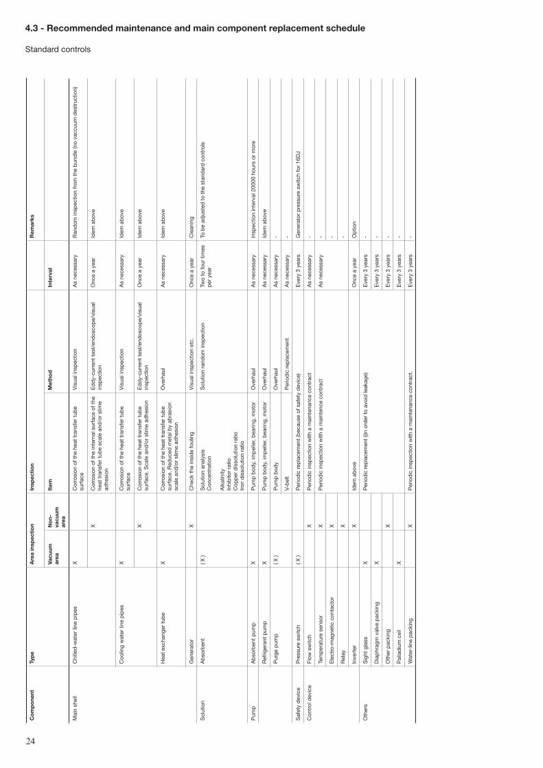
4.3 - recommended maintenance and main component replacement schedule
Standard controls
co
mp
one
ntTy
pe
are
a in
spec
tio
n in
spec
tio
nr
emar
ks
Vacu
um
area
No
n-va
cuum
ar
ea
item
Met
hod
inte
rval
Mai
n sh
ell
Chi
lled
-wat
er li
ne p
ipes
XC
orro
sion
of t
he h
eat
tran
sfer
tub
e su
rfac
eV
isua
l ins
pec
tion
As
nece
ssar
yR
and
om in
spec
tion
from
the
bun
dle
(no
vacc
uum
des
truc
tion)
XC
orro
sion
of t
he in
tern
al s
urfa
ce o
f the
he
at t
rans
fer
tub
e sc
ale
and
/or
slim
e ad
hesi
on
Ed
dy-
curr
ent
test
/end
osco
pe/
visu
al
insp
ectio
nO
nce
a ye
arId
em a
bov
e
Coo
ling
wat
er li
ne p
ipes
XC
orro
sion
of t
he h
eat
tran
sfer
tub
e su
rfac
eV
isua
l ins
pec
tion
As
nece
ssar
yId
em a
bov
e
XC
orro
sion
of t
he h
eat
tran
sfer
tub
e su
rfac
e. S
cale
and
/or
slim
e ad
hesi
onE
dd
y-cu
rren
t te
st/e
ndos
cop
e/vi
sual
in
spec
tion
Onc
e a
year
Idem
ab
ove
Hea
t ex
chan
ger
tub
eX
Cor
rosi
on o
f the
hea
t tr
ansf
er t
ube
surf
ace.
Red
uced
met
al b
y ab
rasi
on
scal
e an
d/o
r sl
ime
adhe
sion
Ove
rhau
lA
s ne
cess
ary
Idem
ab
ove
Gen
erat
orX
Che
ck t
he in
sid
e fo
ulin
gV
isua
l ins
pec
tion
etc.
Onc
e a
year
Cle
anin
g
Sol
utio
nA
bso
rben
t( X
)S
olut
ion
anal
ysis
Con
cent
ratio
n
Alk
alin
ityIn
hib
itor
ratio
Cop
per
dis
solu
tion
ratio
Iron
dis
solu
tion
ratio
Sol
utio
n ra
ndom
insp
ectio
nTw
o to
four
tim
es
per
yea
rTo
be
adju
sted
to
the
stan
dar
d c
ontr
ols
Pum
pA
bso
rben
t p
ump
XP
ump
bod
y, im
pel
ler,
bea
ring,
mot
orO
verh
aul
As
nece
ssar
yIn
spec
tion
inte
rval
200
00 h
ours
or
mor
e
Ref
riger
ant
pum
pX
Pum
p b
ody,
imp
elle
r, b
earin
g, m
otor
Ove
rhau
lA
s ne
cess
ary
Idem
ab
ove
Pur
ge p
ump
( X )
Pum
p b
ody
Ove
rhau
lA
s ne
cess
ary
-
V-b
elt
Per
iod
ic r
epla
cem
ent
As
nece
ssar
y-
Saf
ety
dev
ice
Pre
ssur
e sw
itch
( X )
Per
iod
ic r
epla
cem
ent
(bec
ause
of s
afet
y d
evic
e)E
very
3 y
ears
Gen
erat
or p
ress
ure
switc
h fo
r 16
DJ
Con
trol
dev
ice
Flow
sw
itch
XP
erio
dic
insp
ectio
n w
ith a
mai
nten
ance
con
trac
tA
s ne
cess
ary
-
Tem
per
atur
e se
nsor
XP
erio
dic
insp
ectio
n w
ith a
mai
nten
ce c
ontr
act
As
nece
ssar
y-
Ele
ctro
-mag
netic
con
tact
orX
-
Rel
ayX
-
Inve
rter
XId
em a
bov
eO
nce
a ye
arO
ptio
n
Oth
ers
Sig
ht g
lass
XP
erio
dic
rep
lace
men
t ((i
n or
der
to
avoi
d le
akag
e)E
very
3 y
ears
-
Dia
phr
agm
val
ve p
acki
ngX
Eve
ry 3
yea
rs-
Oth
er p
acki
ngX
Eve
ry 3
yea
rs-
Pal
lad
ium
cel
lX
Eve
ry 3
yea
rs-
Wat
er-l
ine
pac
king
XP
erio
dic
insp
ectio
n w
ith a
mai
nten
ance
con
trac
t.E
very
3 y
ears
-
��
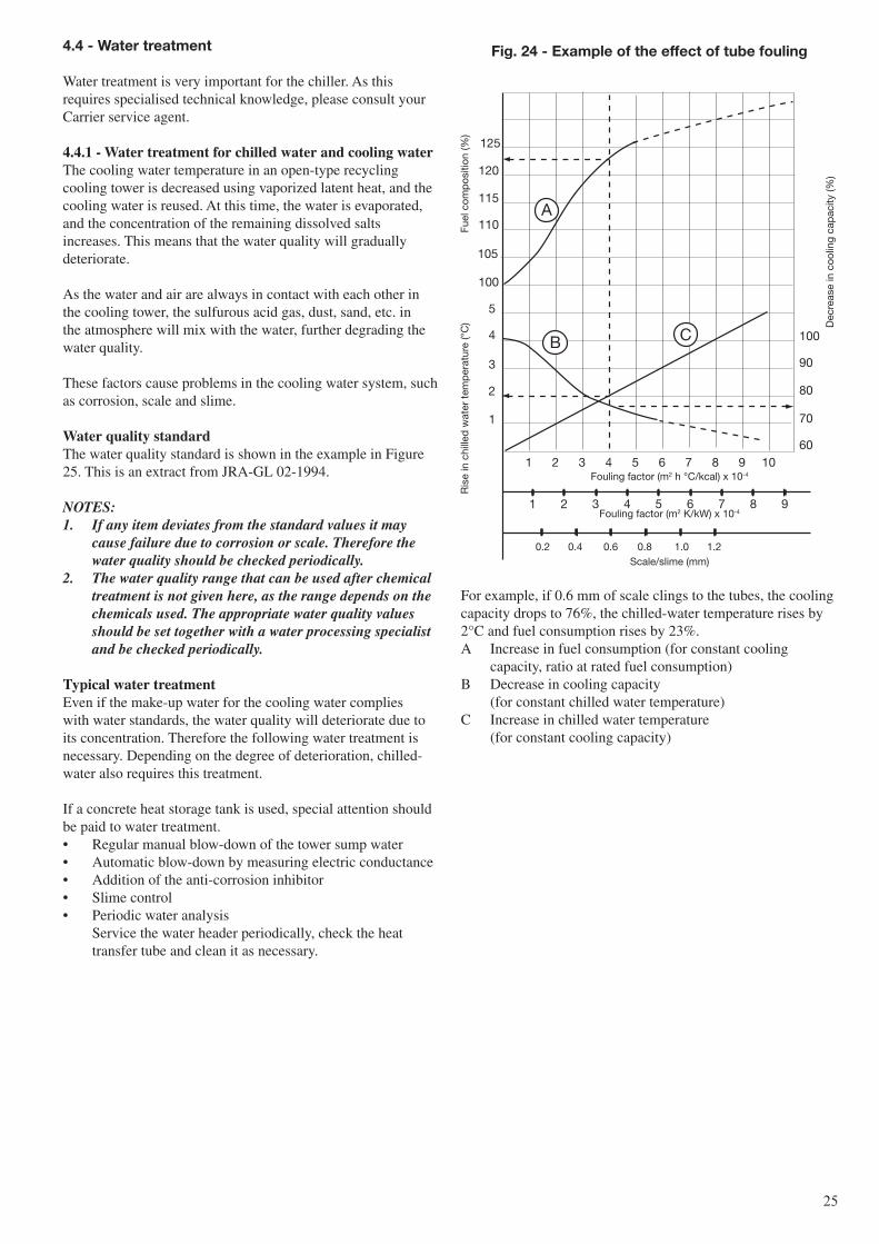
For example, if 0.6 mm of scale clings to the tubes, the cooling capacity drops to 76%, the chilled-water temperature rises by 2°C and fuel consumption rises by 23%.A Increase in fuel consumption (for constant cooling
capacity, ratio at rated fuel consumption)B Decrease in cooling capacity (for constant chilled water temperature)C Increase in chilled water temperature (for constant cooling capacity)
4.4 - Water treatment
Water treatment is very important for the chiller. As this requires specialised technical knowledge, please consult your Carrier service agent.
4.4.1 - Water treatment for chilled water and cooling waterThe cooling water temperature in an open-type recycling cooling tower is decreased using vaporized latent heat, and the cooling water is reused. At this time, the water is evaporated, and the concentration of the remaining dissolved salts increases. This means that the water quality will gradually deteriorate.
As the water and air are always in contact with each other in the cooling tower, the sulfurous acid gas, dust, sand, etc. in the atmosphere will mix with the water, further degrading the water quality.
These factors cause problems in the cooling water system, such as corrosion, scale and slime.
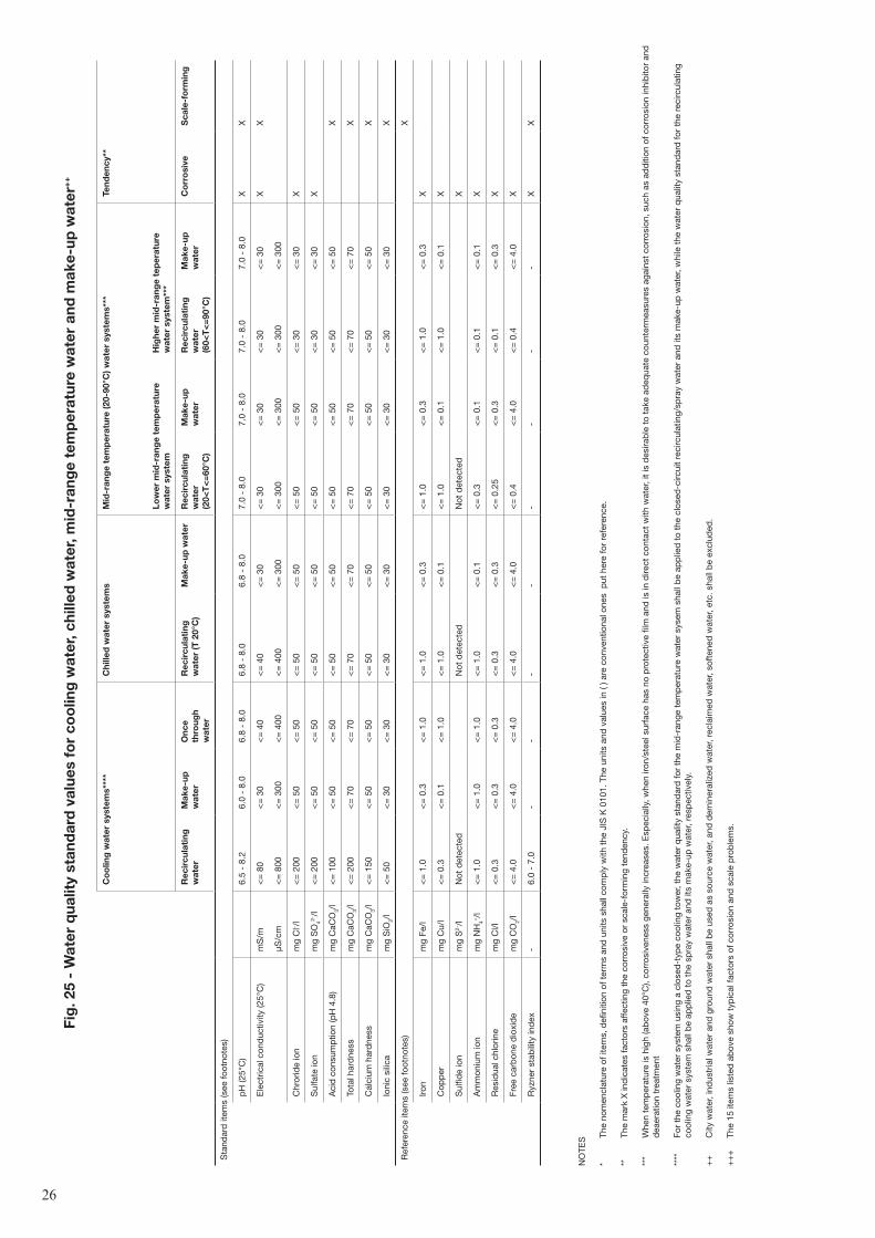
Water quality standardThe water quality standard is shown in the example in Figure 25. This is an extract from JRA-GL 02-1994.
NOTeS:1. If any item deviates from the standard values it may
cause failure due to corrosion or scale. Therefore the water quality should be checked periodically.
2. The water quality range that can be used after chemical treatment is not given here, as the range depends on the chemicals used. The appropriate water quality values should be set together with a water processing specialist and be checked periodically.
Typical water treatmentEven if the make-up water for the cooling water complies with water standards, the water quality will deteriorate due to its concentration. Therefore the following water treatment is necessary. Depending on the degree of deterioration, chilled-water also requires this treatment.
If a concrete heat storage tank is used, special attention should be paid to water treatment.• Regular manual blow-down of the tower sump water• Automatic blow-down by measuring electric conductance• Addition of the anti-corrosion inhibitor• Slime control• Periodic water analysis
Service the water header periodically, check the heat transfer tube and clean it as necessary.
Ris
e in
chi
lled
wat
er t
emp
erat
ure
(°C
)Fu
el c
omp
ositi
on (%
)Fouling factor (m2 h °C/kcal) x 10-4
Fouling factor (m2 K/kW) x 10-4
0.2 0.4 0.6 0.8 1.0 1.2Scale/slime (mm)
Fig. 24 - example of the effect of tube fouling
Dec
reas
e in
coo
ling
cap
acity
(%)
A
B C
125
120
115
110
105
100
5
4
3
2
1
100
90
80
70
601 2 3 4 5 6 7 8 9 10
1 2 3 4 5 6 7 8 9
��
Fig
. 25
- W
ater
qua
lity
stan
dar
d v
alue
s fo
r co
olin
g w
ater
, chi
lled
wat
er, m
id-r
ang
e te
mp
erat
ure
wat
er a
nd m
ake-
up w
ater
++
NO
TES
* Th
e no
men
clat
ure
of it
ems,
defi
nitio
n of
ter
ms
and
uni
ts s
hall
com
ply
with
the
JIS
K 0
101.
The
uni
ts a
nd v
alue
s in
( ) a
re c
onve
ntio
nal o
nes
put
her
e fo
r re
fere
nce.
**
The
mar
k X
ind
icat
es fa
ctor
s af
fect
ing
the
corr
osiv
e or
sca
le-f
orm
ing
tend
ency
.
***
Whe
n te
mp
erat
ure
is h
igh
(ab
ove
40°C
), co
rros
iven
ess
gene
rally
incr
ease
s. E
spec
ially
, whe
n iro
n/st
eel s
urfa
ce h
as n
o p
rote
ctiv
e fil
m a
nd is
in d
irect
con
tact
with
wat
er, i
t is
des
irab
le t
o ta
ke a
deq
uate
cou
nter
mea
sure
s ag
ains
t co
rros
ion,
suc
h as
ad
diti
on o
f cor
rosi
on in
hib
itor
and
d
eaer
atio
n tr
eatm
ent
****
Fo
r th
e co
olin
g w
ater
sys
tem
usi
ng a
clo
sed
-typ
e co
olin
g to
wer
, the
wat
er q
ualit
y st
and
ard
for
the
mid
-ran
ge t
emp
erat
ure
wat
er s
ysem
sha
ll b
e ap
plie
d t
o th
e cl
osed
-circ
uit
reci
rcul
atin
g/sp
ray
wat
er a
nd it
s m
ake-
up w
ater
, whi
le t
he w
ater
qua
lity
stan
dar
d fo
r th
e re
circ
ulat
ing
cool
ing
wat
er s
yste
m s
hall
be
app
lied
to
the
spra
y w
ater
and
its
mak
e-up
wat
er, r
esp
ectiv
ely.
++
C
ity w
ater
, ind
ustr
ial w
ater
and
gro
und
wat
er s
hall
be
used
as
sour
ce w
ater
, and
dem
iner
aliz
ed w
ater
, rec
laim
ed w
ater
, sof
tene
d w
ater
, etc
. sha
ll b
e ex
clud
ed.
++
+
The
15 it
ems
liste
d a
bov
e sh
ow t
ypic
al fa
ctor
s of
cor
rosi
on a
nd s
cale
pro
ble
ms.
co
olin
g w
ater
sys
tem
s***
*c
hille
d w
ater
sys
tem
sM
id-r
ang
e te
mp
erat
ure
(20-
90°c
) wat
er s
yste
ms*
**Te
nden
cy**
low
er m
id-r
ang
e te
mp
erat
ure
wat
er s
yste
mH
ighe
r m
id-r
ang
e te
per
atur
e w
ater
sys
tem
***
rec
ircu
lati
ng
wat
erM
ake-
up
wat
ero
nce
thro
ugh
wat
er
rec
ircu
lati
ng
wat
er (T
20°
c)
Mak
e-up
wat
err
ecir
cula
ting
w
ater
(2
0<T
<=
60°c
)
Mak
e-up
w
ater
rec
ircu
lati
ng
wat
er
(60<
T<
=90
°c)
Mak
e-up
w
ater
co
rro
sive
sca
le-f
orm
ing
Sta
ndar
d it
ems
(see
foot
note
s)
pH
(25°
C)
6.5
- 8.
26.
0 -
8.0
6.8
- 8.
06.
8 -
8.0
6.8
- 8.
07.
0 -
8.0
7.0
- 8.
07.
0 -
8.0
7.0
- 8.
0X
X
Ele
ctric
al c
ond
uctiv
ity (2
5°C
)m
S/m
<=
80
<=
30
<=
40
<=
40
<=
30
<=
30
<=
30
<=
30
<=
30
XX
µS/c
m<
= 8
00<
= 3
00<
= 4
00<
= 4
00<
= 3
00<
= 3
00<
= 3
00<
= 3
00<
= 3
00
Chr
orid
e io
nm
g C
l- /l<
= 2
00<
= 5
0<
= 5
0<
= 5
0<
= 5
0<
= 5
0<
= 5
0<
= 3
0<
= 3
0X
Sul
fate
ion
mg
SO
42-/l
<=
200
<=
50
<=
50
<=
50
<=
50
<=
50
<=
50
<=
30
<=
30
X
Aci
d c
onsu
mp
tion
(pH
4.8
)m
g C
aCO
3/l
<=
100
<=
50
<=
50
<=
50
<=
50
<=
50
<=
50
<=
50
<=
50
X
Tota
l har
dne
ssm
g C
aCO
3/l
<=
200
<=
70
<=
70
<=
70
<=
70
<=
70
<=
70
<=
70
<=
70
X
Cal
cium
har
dne
ssm
g C
aCO
3/l
<=
150
<=
50
<=
50
<=
50
<=
50
<=
50
<=
50
<=
50
<=
50
X
Ioni
c si
lica
mg
SiO
2/l
<=
50
<=
30
<=
30
<=
30
<=
30
<=
30
<=
30
<=
30
<=
30
X
Ref
eren
ce it
ems
(see
foot
note
s)X
Iron
mg
Fe/l
<=
1.0
<=
0.3
<=
1.0
<=
1.0
<=
0.3
<=
1.0
<=
0.3
<=
1.0
<=
0.3
X
Cop
per
mg
Cu/
l<
= 0
.3<
= 0
.1<
= 1
.0<
= 1
.0<
= 0
.1<
= 1
.0<
= 0
.1<
= 1
.0<
= 0
.1X
Sul
fide
ion
mg
S2-/l
Not
det
ecte
dN
ot d
etec
ted
Not
det
ecte
dX
Am
mon
ium
ion
mg
NH
4+/l
<=
1.0
<=
1.0
<=
1.0
<=
1.0
<=
0.1
<=
0.3
<=
0.1
<=
0.1
<=
0.1
X
Res
idua
l chl
orin
em
g C
l/l<
= 0
.3<
= 0
.3<
= 0
.3<
= 0
.3<
= 0
.3<
= 0
.25
<=
0.3
<=
0.1
<=
0.3
X
Free
car
bon
e d
ioxi
de
mg
CO
2/l
<=
4.0
<=
4.0
<=
4.0
<=
4.0
<=
4.0
<=
0.4
<=
4.0
<=
0.4
<=
4.0
X
Ryz
ner
stab
ility
ind
ex-
6.0
- 7.
0-
--
--
--
-X
X
��
5 - TroUblesHooTiNg
For identifying and eliminating the causes of machine failure, please refer to the following chapters:
3.7 - Maintenance message3.8 - Alarm indication and actionsAppendix 1 - Flowchart (at the end of that document)
4.4.2. Water treatment for long-term shut-downPerform the following procedure during long-term shut-down when no chilled-water or cooling water circulates in the chiller. Please consult your Carrier service agent for the details.
Cooling waterThe usual system is a wet system with the cooling water kept in the chiller. If the cooling water is likely to freeze, drain it from the chiller (dry system). The valve operation is different between wet and dry systems.
long-term shut-down (wet system)• Drain the cooling water from its discharge port on the
cooling water outlet.• Add anti-corrosion inhibitor to the water.
Check the holding water quantity and decide the inhibitor quantity so that the ratio is appropriate.
• Charge the chiller with cooling water.• Operate the cooling water pump until the inhibitor is
evenly mixed.• Close the cooling water line inlet and outlet isolation
valves.
Dry systemBefore draining the cooling water from the chiller, clean the inside of the tubes and provide a corrosion protection covering.• Drain the cooling water from its discharge port on the
cooling water inlet.• Remove the scale and/or slime from the tubes with a
brush. If scale and/or slime cannot be removed with a brush use chemical cleaning.
• After sufficient cleaning, add anti-corrosion inhibitor to the water, and circulate the water with the inhibitor for 30 minutes or more. The inhibitor concentration should be even.
• Drain the water from the discharge port on the cooling water inlet.
• Keep the discharge port open during shut-down.
Chilled waterThe usual system is a wet system with the chilled water kept in the chiller.
4.4.3 - Winter seasonIf the ambient temperature of the chiller is likely to be below 0°C in winter, freeze protection is necessary. Consult your Carrier service agent for the details.
��
V2
150
100
280 54
54
V3SV2
V1
SV13
4
5
6
7
1
2
8
9
10
11
12
Sampling cylinder(MATERIAL : ACRYL RESIN)
Valve
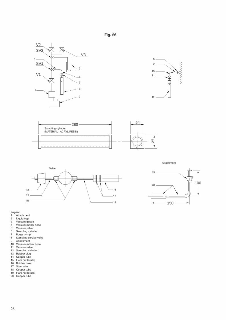
Fig. 26
13
14
15
16
17
18
19
20
Attachment
legend1 Attachment2 Liquid trap3 Vacuum gauge4 Vacuum rubber hose5 Vacuum valve6 Sampling cylinder7 Purge pump8 Sampling service valve9 Attachment10 Vacuum rubber hose11 Vacuum valve12 Sampling cylinder13 Rubber plug14 Copper tube15 Flare nut (brass)16 Rubber hose17 Steel wire18 Copper tube19 Flare nut (brass)20 Copper tube
��
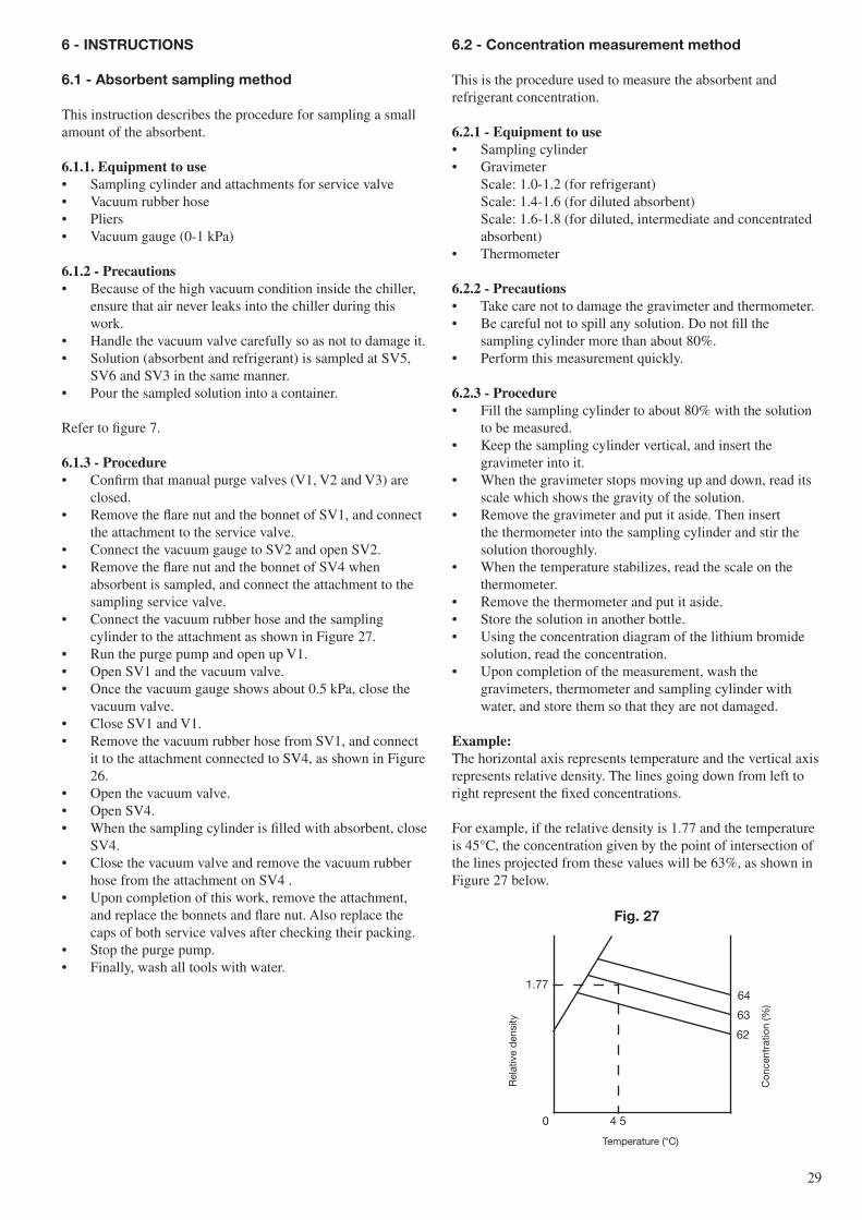
6.2 - concentration measurement method
This is the procedure used to measure the absorbent and refrigerant concentration.
6.2.1 - equipment to use• Sampling cylinder• Gravimeter
Scale: 1.0-1.2 (for refrigerant) Scale: 1.4-1.6 (for diluted absorbent) Scale: 1.6-1.8 (for diluted, intermediate and concentrated absorbent)
• Thermometer
6.2.2 - Precautions• Take care not to damage the gravimeter and thermometer.• Be careful not to spill any solution. Do not fill the
sampling cylinder more than about 80%.• Perform this measurement quickly.
6.2.3 - Procedure• Fill the sampling cylinder to about 80% with the solution
to be measured.• Keep the sampling cylinder vertical, and insert the
gravimeter into it.• When the gravimeter stops moving up and down, read its
scale which shows the gravity of the solution.• Remove the gravimeter and put it aside. Then insert
the thermometer into the sampling cylinder and stir the solution thoroughly.
• When the temperature stabilizes, read the scale on the thermometer.
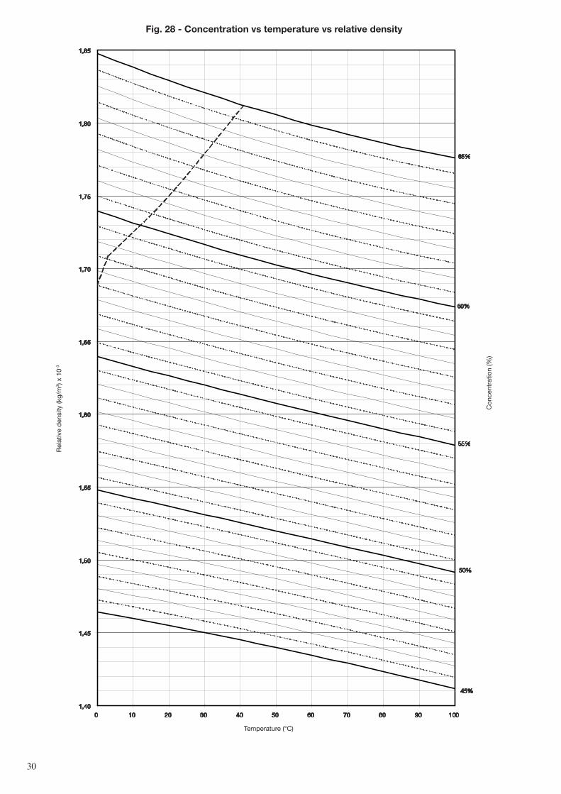
• Remove the thermometer and put it aside.• Store the solution in another bottle.• Using the concentration diagram of the lithium bromide
solution, read the concentration.• Upon completion of the measurement, wash the
gravimeters, thermometer and sampling cylinder with water, and store them so that they are not damaged.
example:The horizontal axis represents temperature and the vertical axis represents relative density. The lines going down from left to right represent the fixed concentrations.
For example, if the relative density is 1.77 and the temperature is 45°C, the concentration given by the point of intersection of the lines projected from these values will be 63%, as shown in Figure 27 below.
Fig. 27
Rel
ativ
e d
ensi
ty
Con
cent
ratio
n (%
)
Temperature (°C)
0 4 5
1.7764
63
62
6 - iNsTrUcTioNs
6.1 - absorbent sampling method
This instruction describes the procedure for sampling a small amount of the absorbent.
6.1.1. equipment to use• Sampling cylinder and attachments for service valve• Vacuum rubber hose• Pliers• Vacuum gauge (0-1 kPa)
6.1.2 - Precautions• Because of the high vacuum condition inside the chiller,
ensure that air never leaks into the chiller during this work.
• Handle the vacuum valve carefully so as not to damage it.• Solution (absorbent and refrigerant) is sampled at SV5,
SV6 and SV3 in the same manner.• Pour the sampled solution into a container.
Refer to figure 7.
6.1.3 - Procedure• Confirm that manual purge valves (V1, V2 and V3) are
closed.• Remove the flare nut and the bonnet of SV1, and connect
the attachment to the service valve.• Connect the vacuum gauge to SV2 and open SV2.• Remove the flare nut and the bonnet of SV4 when
absorbent is sampled, and connect the attachment to the sampling service valve.
• Connect the vacuum rubber hose and the sampling cylinder to the attachment as shown in Figure 27.
• Run the purge pump and open up V1.• Open SV1 and the vacuum valve.• Once the vacuum gauge shows about 0.5 kPa, close the
vacuum valve.• Close SV1 and V1.• Remove the vacuum rubber hose from SV1, and connect
it to the attachment connected to SV4, as shown in Figure 26.
• Open the vacuum valve.• Open SV4.• When the sampling cylinder is filled with absorbent, close
SV4.• Close the vacuum valve and remove the vacuum rubber
hose from the attachment on SV4 .• Upon completion of this work, remove the attachment,
and replace the bonnets and flare nut. Also replace the caps of both service valves after checking their packing.
• Stop the purge pump.• Finally, wash all tools with water.
�0
Fig. 28 - concentration vs temperature vs relative density
Rel
ativ
e d
ensi
ty (k
g/m
3 ) x
10-3
Con
cent
ratio
n (%
)
Temperature (°C)
1,40
1,45
1,50
1,55
1,60
1,65
1,70
1,75
1,80
1,85
0 10 20 30 40 50 60 70 80 90 100
65%
60%
55%
50%
45%
�1
7 - MaiNTeNaNce coNTracT
To enjoy safe and efficient operation of the chiller for a long time, daily maintenance and periodic inspection are essential. The main items are as follows:• Verification of the function of safety devices and their
adjustment• Checking the operating conditions and recording the data
These procedures require special tools and a special skills.
We offer an annual maintenance contract to users of the chiller. Under the contract we provide trained service personnel that will perform the periodic diagnosis and adjustment of the chiller, using the latest technology. Consult your Carrier service agent for details.
7.1 - annual maintenance contract
We offer an annual maintenance contract to our customers with periodic inspection and maintenance of the Carrier absorption chiller. Under this contract your Carrier service agent will perform maintenance/inspection and adjustment works to keep your chiller in its optimal condition, and you will be given priority for chiller repairs, in case there is a problem.
It is recommended to perform a complete chiller overhaul every few years to keep it in its optimal condition. Under the maintenance contract we advise our customers of the timing and the parts to be overhauled. There is an additional contract for water quality control and cleaning of the heat transfer tubes in the water system. We recommend that you also take out this contract.
7.2 - inspection report
We issue an inspection report for the annual maintenance under the contract. The report contains a thorough description of the inspection/adjustment items and ensures that Carrier service personnel will not overlook any of the inspection items. At the time of inspection the Carrier service personnel will fill in the report, leave one copy with the customer, and take one copy back to the office to be available for future maintenance works.
We will not re-issue this report, so please be sure to keep it in a safe place. Show it to the Carrier service technicians when they visit you.
7.3 - Warranty
• Your Carrier service agent will fill in the warranty and leave it with you. Please check the warranty period, read the document carefully and keep it in a safe place.
• If the chiller fails within the warranty period under normal operating conditions, we will replace all necessary spare parts or repair the chiller free-of-charge.
• After the warranty period expires, all repair costs will be charged. Consult your service agent.
• For all other items please read your warranty document.
��
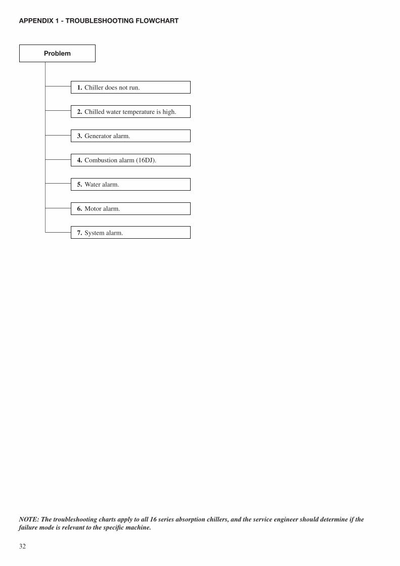
aPPeNDix 1 - TroUblesHooTiNg FloWcHarT
1. Chiller does not run.
2. Chilled water temperature is high.
3. Generator alarm.
4. Combustion alarm (16DJ).
5. Water alarm.
6. Motor alarm.
7. System alarm.
Problem
NOTe: The troubleshooting charts apply to all 16 series absorption chillers, and the service engineer should determine if the failure mode is relevant to the specific machine.
��
aPPeNDix 1 - TroUblesHooTiNg FloWcHarT - coNT.
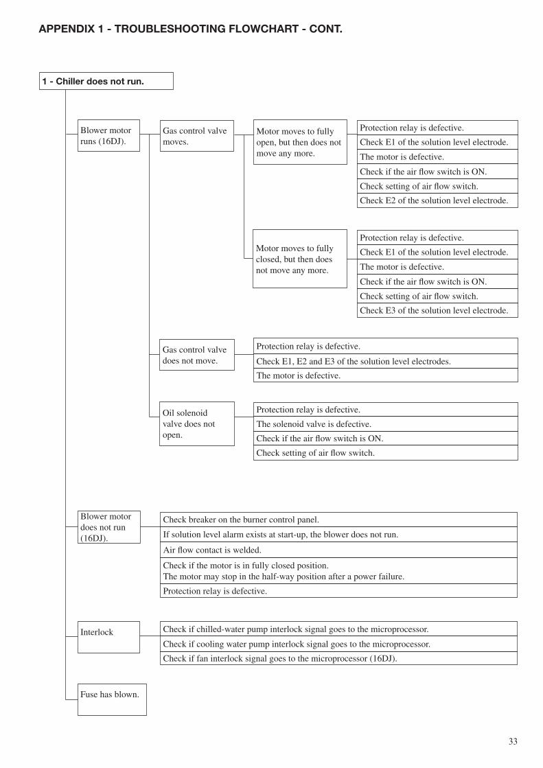
1 - chiller does not run.
Blower motorruns (16DJ).
Gas control valvemoves.
Motor moves to fully open, but then does not move any more.
Motor moves to fully closed, but then does not move any more.
Check E2 of the solution level electrode.
Check setting of air flow switch.
Check if the air flow switch is ON.
The motor is defective.
Check E1 of the solution level electrode.
Protection relay is defective.
Check E3 of the solution level electrode.
Check setting of air flow switch.
Check if the air flow switch is ON.
The motor is defective.
Check E1 of the solution level electrode.
Protection relay is defective.
Gas control valvedoes not move.
Oil solenoidvalve does notopen.
Protection relay is defective.
Check E1, E2 and E3 of the solution level electrodes.
The motor is defective.
Protection relay is defective.
The solenoid valve is defective.
Check if the air flow switch is ON.
Check setting of air flow switch.
Blower motordoes not run (16DJ).
Interlock
Fuse has blown.
Check if chilled-water pump interlock signal goes to the microprocessor.
Check if cooling water pump interlock signal goes to the microprocessor.
Check if fan interlock signal goes to the microprocessor (16DJ).
Check breaker on the burner control panel.
If solution level alarm exists at start-up, the blower does not run.
Check if the motor is in fully closed position.The motor may stop in the half-way position after a power failure.
Air flow contact is welded.
Protection relay is defective.
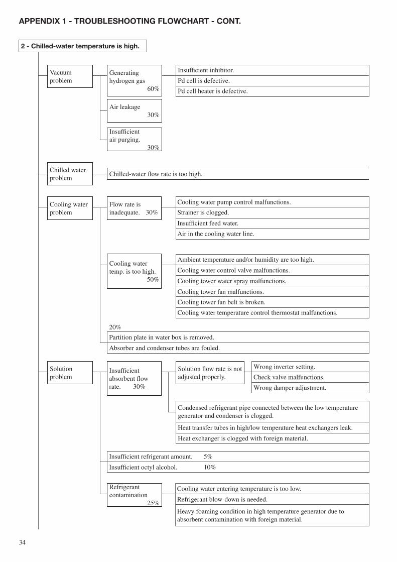
��
2 - chilled-water temperature is high.
Vacuumproblem
Generatinghydrogen gas
60%
Air leakage30%
Insufficientair purging.
30%
Chilled waterproblem
Chilled-water flow rate is too high.
Cooling waterproblem
Flow rate isinadequate. 30%
Cooling watertemp. is too high.
50%
Solutionproblem
Insufficient absorbent flow rate. 30%
Solution flow rate is not adjusted properly.
Refrigerantcontamination 25%
aPPeNDix 1 - TroUblesHooTiNg FloWcHarT - coNT.
20%
Partition plate in water box is removed.
Absorber and condenser tubes are fouled.
Wrong inverter setting.
Check valve malfunctions.
Wrong damper adjustment.
Condensed refrigerant pipe connected between the low temperature generator and condenser is clogged.
Heat transfer tubes in high/low temperature heat exchangers leak.
Heat exchanger is clogged with foreign material.
Insufficient refrigerant amount. 5%
Insufficient octyl alcohol. 10%
Cooling water entering temperature is too low.
Refrigerant blow-down is needed.
Heavy foaming condition in high temperature generator due toabsorbent contamination with foreign material.
Ambient temperature and/or humidity are too high.
Cooling water control valve malfunctions.
Cooling tower water spray malfunctions.
Cooling tower fan malfunctions.
Cooling tower fan belt is broken.
Cooling water temperature control thermostat malfunctions.
Cooling water pump control malfunctions.
Strainer is clogged.
Insufficient feed water.
Air in the cooling water line.
Insufficient inhibitor.
Pd cell is defective.
Pd cell heater is defective.
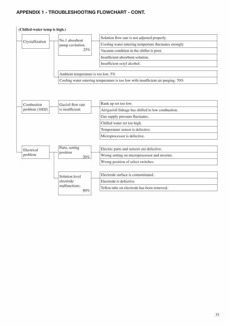
��
(Chilled-water temp is high.)
aPPeNDix 1 - TroUblesHooTiNg FloWcHarT - coNT.
Crystallization No.1 absorbentpump cavitation.
25%
Combustionproblem (16DJ)
Gas/oil flow rateis insufficient.
Electricalproblem
Parts, settingposition
20%
Solution levelelectrodemalfunctions.
80%
Solution flow rate is not adjusted properly.
Cooling water entering temperture fluctuates strongly
Vacuum condition in the chiller is poor.
Insufficient absorbent solution.
Insufficient octyl alcohol.
Ambient temperature is too low. 5%
Cooling water entering temperature is too low with insufficient air purging. 70%
Rank up set too low.
Air/gas/oil linkage has shifted to low combustion.
Gas supply pressure fluctuates.
Chilled water set too high.
Temperature sensor is defective.
Microprocessor is defective.
Electric parts and sensors are defective.
Wrong setting on microprocessor and inverter.
Wrong position of select switches.
Electrode surface is contaminated.
Electrode is defective.
Teflon tube on electrode has been removed.
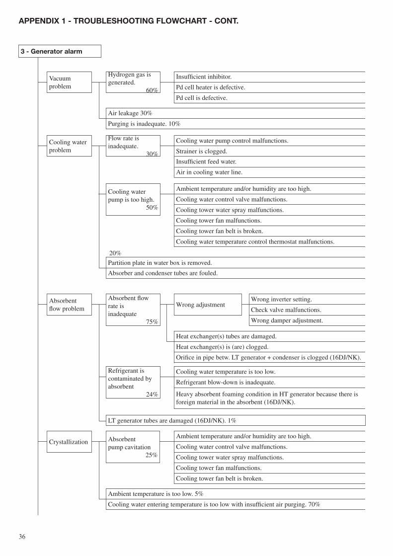
��
Vacuum problem
Hydrogen gas isgenerated.
60%
Cooling water problem
Flow rate isinadequate.
30%
Cooling waterpump is too high.
50%
Absorbentflow problem
Absorbent flowrate isinadequate
75%
Wrong adjustment
Refrigerant iscontaminated byabsorbent
24%
LT generator tubes are damaged (16DJ/NK). 1%
Crystallization Absorbentpump cavitation
25%
3 - generator alarm
aPPeNDix 1 - TroUblesHooTiNg FloWcHarT - coNT.
Insufficient inhibitor.
Pd cell heater is defective.
Pd cell is defective.
Air leakage 30%
Purging is inadequate. 10%
Cooling water pump control malfunctions.
Strainer is clogged.
Insufficient feed water.
Air in cooling water line.
Ambient temperature and/or humidity are too high.
Cooling water control valve malfunctions.
Cooling tower water spray malfunctions.
Cooling tower fan malfunctions.
Cooling tower fan belt is broken.
Cooling water temperature control thermostat malfunctions.
Partition plate in water box is removed.
Absorber and condenser tubes are fouled.
Wrong inverter setting.
Check valve malfunctions.
Wrong damper adjustment.
Heat exchanger(s) tubes are damaged.
Heat exchanger(s) is (are) clogged.
Orifice in pipe betw. LT generator + condenser is clogged (16DJ/NK).
Cooling water temperature is too low.
Refrigerant blow-down is inadequate.
Heavy absorbent foaming condition in HT generator because there is foreign material in the absorbent (16DJ/NK).
Ambient temperature and/or humidity are too high.
Cooling water control valve malfunctions.
Cooling tower water spray malfunctions.
Cooling tower fan malfunctions.
Cooling tower fan belt is broken.
Ambient temperature is too low. 5%
Cooling water entering temperature is too low with insufficient air purging. 70%
20%

��
Electricalparts problem
Electrical parts/sensorsmalfunction 20%
Solution levelelectrodemalfunctions 80%
High-temp. generator problem (16DJ)
Combustionchamber andsmoke tube aresooted 90%
Too much gas/oil 8%
Baffles provided in smoke tube are defective. 2%
aPPeNDix 1 - TroUblesHooTiNg FloWcHarT - coNT.
(generator alarm)
Microprocessor malfunctions.
Cam switches malfunction.
Pressure switch malfunctions.
Microprocessor solution level incorrect.
Temperature sensor malfunctions.
Electrode surface is contaminated.
Electrode is defective.
Teflon tube on electrode has been removed.
Incorrect combustion adjustment.
Blower suction is clogged ‡ air/gas/oil ratio is incorrect.
Flue is clogged ‡ air/gas/oil ratio is incorrect.
Gas pressure increases.
Incorrect gas/oil linkage adjustment.
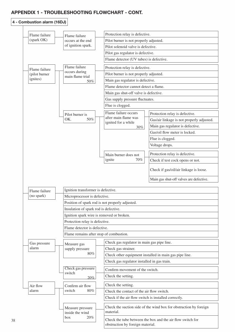
��
Flame failure(spark OK)
Flame failureoccurs at the end of ignition spark.
Flame failure(pilot burnerignites)
Flame failureoccurs during main flame trial
50%
Pilot burner isOK. 50%
Flame failure occursafter main flame was ignited for a while
30%
Main burner does notignite 70%
Flame failure(no spark)
Gas pressurealarm
Measure gassupply pressure
80%
Check gas pressure switch
20%
Air flowalarm
Confirm air flowswitch 80%
Measure pressureinside the windbox 20%
4 - combustion alarm (16DJ)
aPPeNDix 1 - TroUblesHooTiNg FloWcHarT - coNT.
Protection relay is defective.
Pilot burner is not properly adjusted.
Pilot solenoid valve is defective.
Pilot gas regulator is defective.
Flame detector (UV tubes) is defective.
Protection relay is defective.
Pilot burner is not properly adjusted.
Main gas regulator is defective.
Flame detector cannot detect a flame.
Main gas shut-off valve is defective.
Gas supply pressure fluctuates.
Flue is clogged.
Protection relay is defective.
Gas/air linkage is not properly adjusted.
Main gas regulator is defective.
Gas/oil flow meter is locked.
Flue is clogged.
Voltage drops.
Protection relay is defective.
Check if test cock opens or not.
Check if gas/oil/air linkage is loose.
Main gas shut-off valves are defective.
Ignition transformer is defective.
Microprocessor is defective.
Position of spark rod is not properly adjusted.
Insulation of spark rod is defective.
Ignition spark wire is removed or broken.
Protection relay is defective.
Flame detector is defective.
Flame remains after stop of combustion.
Check gas regulator in main gas pipe line.
Check gas strainer.
Check other equipment installed in main gas pipe line.
Check gas regulator installed in gas train.
Confirm movement of the switch.
Check the setting.
Check the setting.
Check the contact of the air flow switch.
Check if the air flow switch is installed correctly.
Check the suction side of the wind box for obstruction by foreignmaterial.
Check the tube between the box and the air flow switch forobstruction by foreign material.
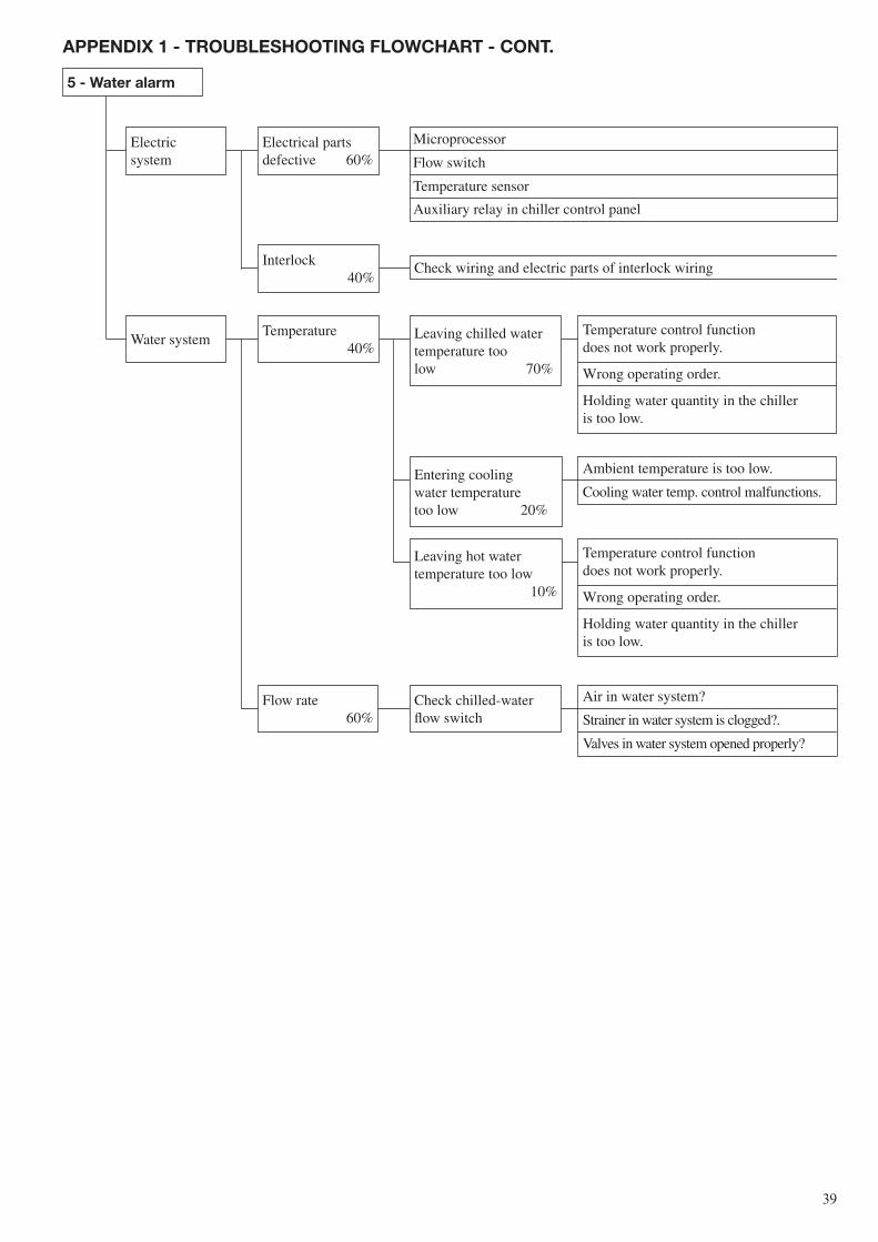
��
5 - Water alarm
Electricsystem
Electrical partsdefective 60%
Interlock40%
Check wiring and electric parts of interlock wiring
Water systemTemperature
40%Leaving chilled watertemperature toolow 70%
Entering coolingwater temperaturetoo low 20%
Leaving hot watertemperature too low
10%
Flow rate60%
Check chilled-waterflow switch
aPPeNDix 1 - TroUblesHooTiNg FloWcHarT - coNT.
Microprocessor
Flow switch
Temperature sensor
Auxiliary relay in chiller control panel
Temperature control functiondoes not work properly.
Wrong operating order.
Holding water quantity in the chilleris too low.
Ambient temperature is too low.
Cooling water temp. control malfunctions.
Temperature control functiondoes not work properly.
Wrong operating order.
Holding water quantity in the chilleris too low.
Air in water system?
Strainer in water system is clogged?.
Valves in water system opened properly?
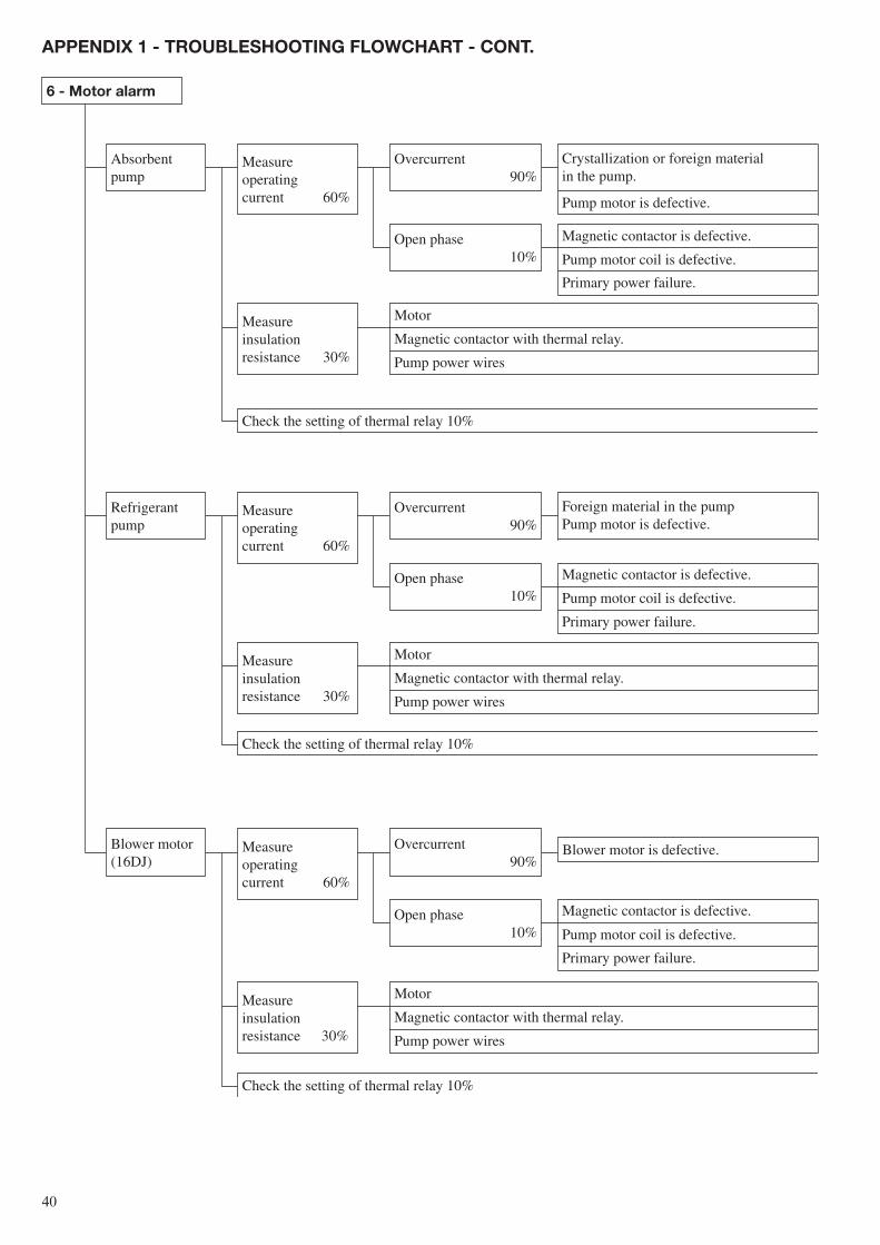
�0
6 - Motor alarm
Absorbentpump
Measureoperatingcurrent 60%
Overcurrent90%
Open phase10%
Measureinsulationresistance 30%
Check the setting of thermal relay 10%
Refrigerantpump
Measureoperatingcurrent 60%
Overcurrent90%
Open phase10%
Measureinsulationresistance 30%
Check the setting of thermal relay 10%
Blower motor (16DJ)
Measureoperatingcurrent 60%
Overcurrent90%
Open phase10%
Measureinsulationresistance 30%
Check the setting of thermal relay 10%
Blower motor is defective.
aPPeNDix 1 - TroUblesHooTiNg FloWcHarT - coNT.
Crystallization or foreign materialin the pump.
Pump motor is defective.
Magnetic contactor is defective.
Pump motor coil is defective.
Primary power failure.
Motor
Magnetic contactor with thermal relay.
Pump power wires
Foreign material in the pumpPump motor is defective.
Magnetic contactor is defective.
Pump motor coil is defective.
Primary power failure.
Motor
Magnetic contactor with thermal relay.
Pump power wires
Magnetic contactor is defective.
Pump motor coil is defective.
Primary power failure.
Motor
Magnetic contactor with thermal relay.
Pump power wires
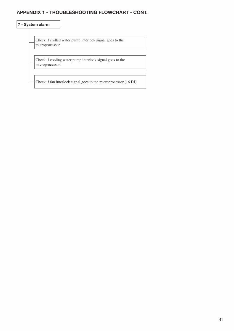
�1
Check if chilled water pump interlock signal goes to the microprocessor.
Check if cooling water pump interlock signal goes to the microprocessor.
Check if fan interlock signal goes to the microprocessor (16 DJ).
7 - system alarm
aPPeNDix 1 - TroUblesHooTiNg FloWcHarT - coNT.

Order No.: 11��0-��, 0�.�00�. Supersedes order No.: New Manufactured by: Sanyo Electric Co. Ltd., Dalian, China Manufacturer reserves the right to change any product specifications without notice. Printed in the Netherlands on totally chlorine-free paper.
GB/T-24001 to ISO14001:1996