116nk 11-81 double effect steam absorption chillers...
TRANSCRIPT
SUPER ABSORPTION
1
2
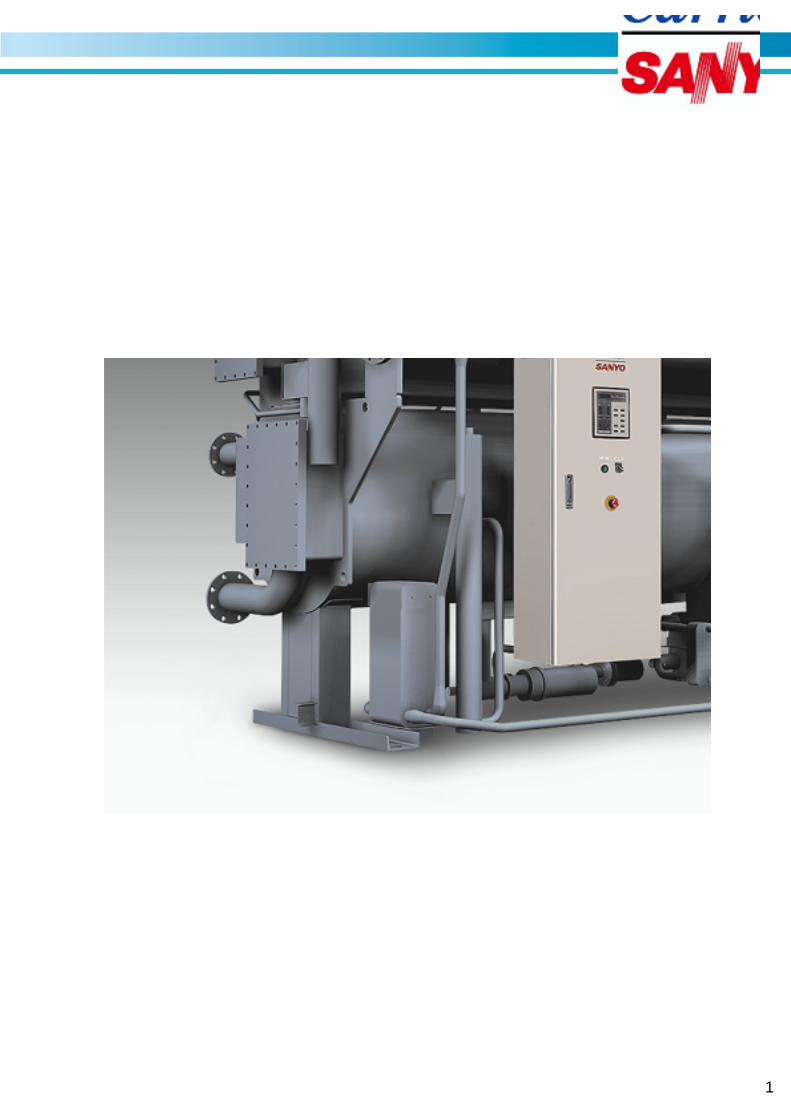
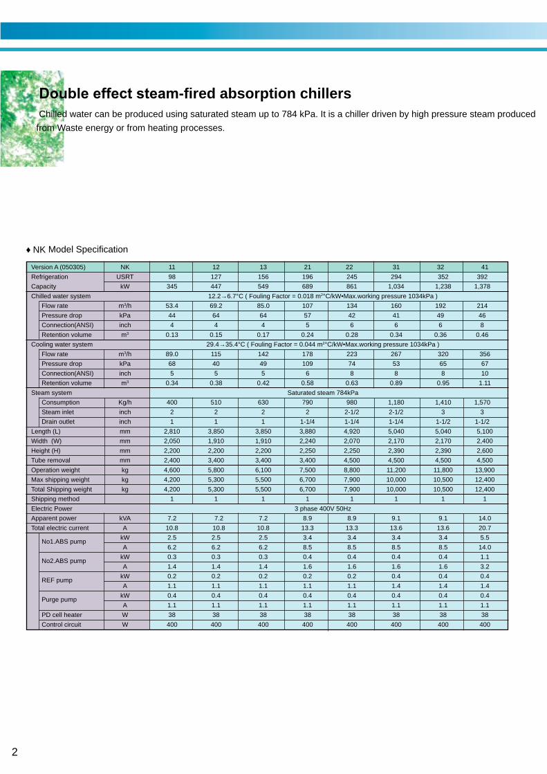
Double effect steam-fired absorption chillersChilled water can be produced using saturated steam up to 784 kPa. It is a chiller driven by high pressure steam produced
from Waste energy or from heating processes. ♦ NK Model Specification
Version A (050305) NK 11 12 13 21 22 31 32 41
Refrigeration USRT 98 127 156 196 245 294 352 392
Capacity kW 345 447 549 689 861 1,034 1,238 1,378
Chilled water system 12.2→6.7°C ( Fouling Factor = 0.018 m2°C/kW•Max.working pressure 1034kPa )
Flow rate m3/h 53.4 69.2 85.0 107 134 160 192 214
Pressure drop kPa 44 64 64 57 42 41 49 46
Connection(ANSI) inch 4 4 4 5 6 6 6 8
Retention volume m3 0.13 0.15 0.17 0.24 0.28 0.34 0.36 0.46
Cooling water system 29.4→35.4°C ( Fouling Factor = 0.044 m2°C/kW•Max.working pressure 1034kPa )
Flow rate m3/h 89.0 115 142 178 223 267 320 356
Pressure drop kPa 68 40 49 109 74 53 65 67
Connection(ANSI) inch 5 5 5 6 8 8 8 10
Retention volume m3 0.34 0.38 0.42 0.58 0.63 0.89 0.95 1.11
Steam system Saturated steam 784kPa
Consumption Kg/h 400 510 630 790 980 1,180 1,410 1,570
Steam inlet inch 2 2 2 2 2-1/2 2-1/2 3 3
Drain outlet inch 1 1 1 1-1/4 1-1/4 1-1/4 1-1/2 1-1/2
Length (L) mm 2,810 3,850 3,850 3,880 4,920 5,040 5,040 5,100
Width (W) mm 2,050 1,910 1,910 2,240 2,070 2,170 2,170 2,400
Height (H) mm 2,200 2,200 2,200 2,250 2,250 2,390 2,390 2,600
Tube removal mm 2,400 3,400 3,400 3,400 4,500 4,500 4,500 4,500
Operation weight kg 4,600 5,800 6,100 7,500 8,800 11,200 11,800 13,900
Max shipping weight kg 4,200 5,300 5,500 6,700 7,900 10,000 10,500 12,400
Total Shipping weight kg 4,200 5,300 5,500 6,700 7,900 10,000 10,500 12,400
Shipping method 1 1 1 1 1 1 1 1
Electric Power 3 phase 400V 50Hz
Apparent power kVA 7.2 7.2 7.2 8.9 8.9 9.1 9.1 14.0
Total electric current A 10.8 10.8 10.8 13.3 13.3 13.6 13.6 20.7
No1.ABS pumpkW 2.5 2.5 2.5 3.4 3.4 3.4 3.4 5.5
A 6.2 6.2 6.2 8.5 8.5 8.5 8.5 14.0
No2.ABS pumpkW 0.3 0.3 0.3 0.4 0.4 0.4 0.4 1.1
A 1.4 1.4 1.4 1.6 1.6 1.6 1.6 3.2
REF pumpkW 0.2 0.2 0.2 0.2 0.2 0.4 0.4 0.4
A 1.1 1.1 1.1 1.1 1.1 1.4 1.4 1.4
Purge pumpkW 0.4 0.4 0.4 0.4 0.4 0.4 0.4 0.4
A 1.1 1.1 1.1 1.1 1.1 1.1 1.1 1.1
PD cell heater W 38 38 38 38 38 38 38 38
Control circuit W 400 400 400 400 400 400 400 400
SUPER ABSORPTION
3
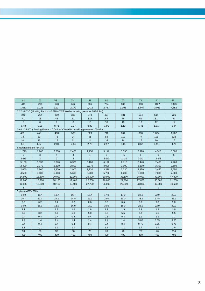
42 51 52 53 61 62 63 71 72 81
441 490 548 617 686 784 882 980 1127 1323
1,551 1,723 1,927 2,170 2,412 2,757 3,101 3,446 3,963 4,652
12.2→6.7°C ( Fouling Factor = 0.018 m2°C/kW•Max.working pressure 1034kPa )
240 267 299 336 374 427 481 534 614 721
41 98 46 61 123 83 78 54 81 84
8 8 8 8 10 10 10 12 12 14
0.48 0.65 0.71 0.77 0.99 1.06 1.13 1.41 1.61 1.94
29.4→35.4°C ( Fouling Factor = 0.044 m2°C/kW•Max.working pressure 1034kPa )
401 445 498 560 623 712 801 890 1,024 1,202
73 53 71 94 61 83 111 77 113 122
10 12 12 12 14 14 14 16 16 16
1.9 1.87 2.01 2.14 2.79 2.97 3.15 3.67 4.11 4.76
Saturated steam 784kPa
1,770 1,960 2,200 2,470 2,750 3,140 3,530 3,920 4,510 5,300
3 3 4 4 4 5 5 6 6 6
1-1/2 2 2 2 2 2-1/2 2-1/2 2-1/2 2-1/2 3
5,100 5,330 5,870 6,370 6,100 6,190 6,710 6,440 7,460 7,460
2,400 2,770 2,800 2,800 2,970 3,000 3,000 3,300 3,300 3,500
2,600 2,900 2,900 2,900 3,330 3,330 3,330 3,450 3,450 3,650
4,500 4,600 5,100 5,600 5,200 5,700 6,200 6,000 7,000 7,000
14,500 18,800 20,800 22,300 26,500 30,000 32,100 38,000 42,300 47,300
12,800 16,300 18,100 19,400 22,700 26,000 27,800 27,800 30,600 21,700
12,800 16,300 18,100 19,400 22,700 26,000 27,800 33,000 36,600 40,600
1 1 1 1 1 1 1 1 1 3
3 phase 400V 50Hz
14.0 15.4 16.7 16.7 17.4 17.0 17.0 22.9 22.9 22.9
20.7 22.7 24.5 24.5 25.5 25.0 25.0 33.5 33.5 33.5
5.5 6.2 6.2 6.2 6.6 6.6 6.6 9.0 9.0 9.0
14.0 16.0 16.0 16.0 17.0 16.0 16.0 22.0 22.0 22.0
1.1 1.1 1.8 1.8 1.8 1.9 1.9 1.9 1.9 1.9
3.2 3.2 5.0 5.0 5.0 5.5 5.5 5.5 5.5 5.5
0.4 0.4 0.4 0.4 0.4 0.3 0.3 1.1 1.1 1.1
1.4 1.4 1.4 1.4 1.4 1.4 1.4 3.05 3.05 3.05
0.4 0.4 0.4 0.4 0.4 0.4 0.4 0.75 0.75 0.75
1.1 1.1 1.1 1.1 1.1 1.1 1.1 1.9 1.9 1.9
38 38 38 38 76 76 76 76 76 114
400 400 400 400 400 400 400 400 400 400
4
Scope of supply (NK)
1.Standard
ARI 560-2000
89/392/EEC (MD)
73/23/EEC (LVD)
89/336/EEC (EMC)
97/23/EC (PED)
2.Absorption chiller
Parts and instruments in the chiller are selected
by manufacturer.
(1)Lower shell
•Evaporator and refrigerant tray
•Absorber and absorbent tray
•Eliminators
•Bases
(2)Upper shell
•Generator
•Condenser
•Low temperature(LT) generator
•Eliminators
•Rupture disk mounting flange
(3) High temperature (HT) generator
(4)Heat exchangers
•High temperature (HT) heat exchanger
•Low temperature (LT) heat exchanger
•Refrigerant drain heat reclaimer
•HT steam drain heat reclaimer
•LT steam drain heat reclaimer
(5)Pumps
•Absorbent pumps with isolation valves
•Refrigerant pump with isoration valves
•Purge pump
(6)Purge unit
•Strage tank
•Ejector device
•Liquid trap
•Piping and deaphragm valves
•Palladium cell with heater
•Pressure sencor
(7)Steam trap
(8)Control panel
•Controller with data display. Lamps and operation buttons.
•Inverter for absorbent pump.
•Circuit breaker.
•Transformer.
•Relays and terminal blocks.
•Purge pump oeration switch.
(9)Locally mouted parts
•Temperature sensors
•Chilled water flow switch
•Generator pressure switchs
(10) Interconnecting piping and wiring
•Refrigerant and absorbent piping
•Internal power and control wiring
(11) Initial charge
•Absorbent (Lithium Bromide)
•Refrigerant(Water)
•Inhibitor(Lithium Molibdate)
(12) Painting
•Main unit: Rust priventive paint
•Control panel: Finish paint
(13) Accessory
•See attached accessory parts list
3.Factory test
•Check of external dimensions
•Hydraulic pressure test of water headers Test pressure is 1.5 times
of maximum working pressure
•Leak test of vacuum side
•Electroc insulation resistance test
•Dielectric breakdown test
•Function test of electric circuit and safety devices
4.Scop of supply of purchaser
(1)Unloading, Transportation and insurance after port of near
manufacturer.
(2)Building and foundations.
(3)External chilled water, cooling water and steam piping
work including various safety valves. isoration valves,
mating flanges, gaskets, bolts and nuts, etc.
(4)External wiring and piping for the chiller including
necessary parts.
(5) Insulation for the chiller.
(6)Finish painting of the chiller.
(7)Cooling water inlet temperature control device.
(8)Water treatment device of cooling water.
(9)Various temp./press. gauges for water, steam and drain lines.
(10) Cooling tower(s), chilled water pump(s),
cooling water pump(s) and steam two way control valve.
(11) Electric power supply (specified value).
(12) Supply of chilled water, cooling water and steam at rated
conditions.
(13) Maintenance of the chiller.
(14) Necessary tools, workers and materials for installation and
site testing.
(15) Any other items without the scope of supply.
SUPER ABSORPTION
5
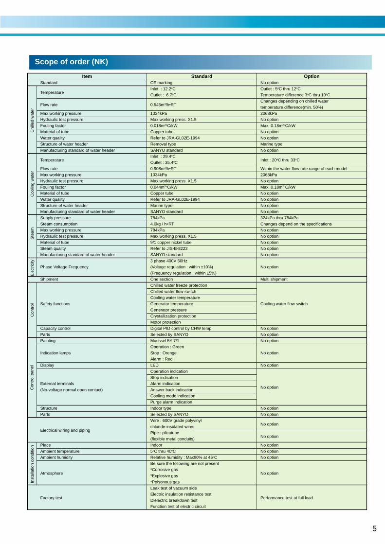
The heating cycleScope of order (NK)
Item Standard OptionStandard CE marking No option
TemperatureInlet : 12.2oC Outlet : 5oC thru 12oC
Outlet : 6.7oC Temperature difference 3oC thru 10oC
Flow rate 0.545m3/h•RTChanges depending on chilled water
temperature difference(min. 50%)
Max.working pressure 1034kPa 2068kPa
Hydraulic test pressure Max.working press. X1.5 No option
Fouling factor 0.018m2oC/kW Max. 0.18m2oC/kW
Material of tube Copper tube No option
Water quality Refer to JRA-GL02E-1994 No option
Structure of water header Removal type Marine type
Manufacturing standard of water header SANYO standard No option
TemperatureInlet : 29.4oC
Inlet : 20oC thru 33oCOutlet : 35.4oC
Flow rate 0.908m3/h•RT Within the water flow rate range of each model
Max.working pressure 1034kPa 2068kPa
Hydraulic test pressure Max.working press. X1.5 No option
Fouling factor 0.044m2oC/kW Max. 0.18m2oC/kW
Material of tube Copper tube No option
Water quality Refer to JRA-GL02E-1994 No option
Structure of water header Marine type No option
Manufacturing standard of water header SANYO standard No option
Supply pressure 784kPa 324kPa thru 784kPa
Steam consumption 4.0kg / h•RT Changes depend on the specifications
Max.working pressure 784kPa No option
Hydraulic test pressure Max.working press. X1.5 No option
Material of tube 9/1 copper nickel tube No option
Steam quality Refer to JIS-B-8223 No option
Manufacturing standard of water header SANYO standard No option
3 phase 400V 50Hz
Phase Voltage Frequency (Voltage regulation : within ±10%) No option
(Frequency regulation : within ±5%)
Shipment One section Multi shipment
Chilled water freeze protection
Chilled water flow switch
Cooling water temperature
Safety functions Generator temperature Cooling water flow switch
Generator pressure
Crystallization protection
Motor protection
Capacity control Digital PID control by CHW temp No option
Parts Selected by SANYO No option
Painting Munssel 5Y-7/1 No option
Operation : Green
Indication lamps Stop : Orenge No option
Alarm : Red
Display LED No option
Operation indication
Stop indication
External terminals Alarm indicationNo option
(No-voltage normal open contact) Answer back indication
Cooling mode indication
Purge alarm indication
Structure Indoor type No option
Parts Selected by SANYO No option
Wire : 600V grade polyvinylNo option
Electrical wiring and pipingchloride-insulated wires
Pipe : plicatubeNo option
(flexible metal conduits)
Place Indoor No option
Ambient temperature 5oC thru 40oC No option
Ambient humidity Relative humidity : Max90% at 45oC No option
Be sure the following are not present
Atmosphere*Corrosive gas
No option*Explosive gas
*Poisonous gas
Leak test of vacuum side
Factory testElectric insulation resistance test
Performance test at full loadDielectric breakdown test
Function test of electric circuit
Con
trol
pan
elIn
stal
latio
n co
nditi
onC
ontr
olS
team
Coo
ling
wat
erE
lect
ricity
Chi
lled
wat
er
6
0
595
923
1263
0
Dra
in o
utle
t
Ste
am in
let
Rup
ture
Dis
k2
inch
2 in
ch
1 in
ch
2200
(H)
0
995
207
1810
279
150
1809
2050
(W)
300
1921
1350
01904
2400
(Tub
e re
mov
al)
2810
(L)
0
323
0180200364
1896
CH
W in
let/o
utle
tC
OW
inle
t/out
let
66877
0
Wire
con
nect
ion
0
900
982
R6001083
24362291
374
634
1240
CO
W o
utle
t5
inch
CH
W o
utle
t4
inch
CO
W in
tlet
5 in
ch
CH
W in
tlet
4 in
ch
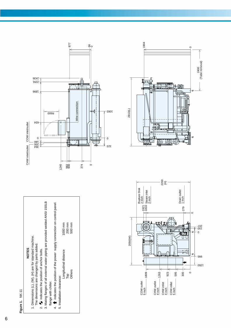
Fig
ure
1. N
K-1
1
N
OT
ES
1. D
imen
sion
s (L
), (
W),
(H
) ar
e fo
r st
anda
rd m
achi
ne.
The
dim
ensi
ons
are
chan
ged
by p
arts
add
ed.
2. in
dica
tes
the
posi
tion
of a
ncho
r bo
lts.
3.M
atin
g fla
nges
of a
ll ex
tern
al w
ater
pip
ing
are
prov
ided
wel
ded
AN
SI 1
50LB
flang
e w
ith c
hille
r.
4. in
dica
tes
the
posi
tion
of th
e po
wer
sup
ply
conn
ectio
n on
con
trol
pan
el.
5. In
stal
latio
n cl
eara
nce: Lo
ngitu
dina
l dis
tanc
e10
00 m
mTo
p20
0 m
mO
ther
s50
0 m
m
7
Dra
in o
utle
t
Ste
am in
let
Rup
ture
Dis
k2
inch
2 in
ch
1 in
ch
CH
W o
utle
tC
HW
inle
tC
OW
inle
tC
OW
out
let
0
0
0
2200
(H)
1910
(W)
300
595
923
1263
1809
207152
1810
1921
1350
01904
3400
(Tub
e re
mov
al)
3850
(L)
66877
0
0
00
Wire
con
nect
ion
323
1781
900
982
180200
541
2916
31163264
R600
396
2620
371
1240
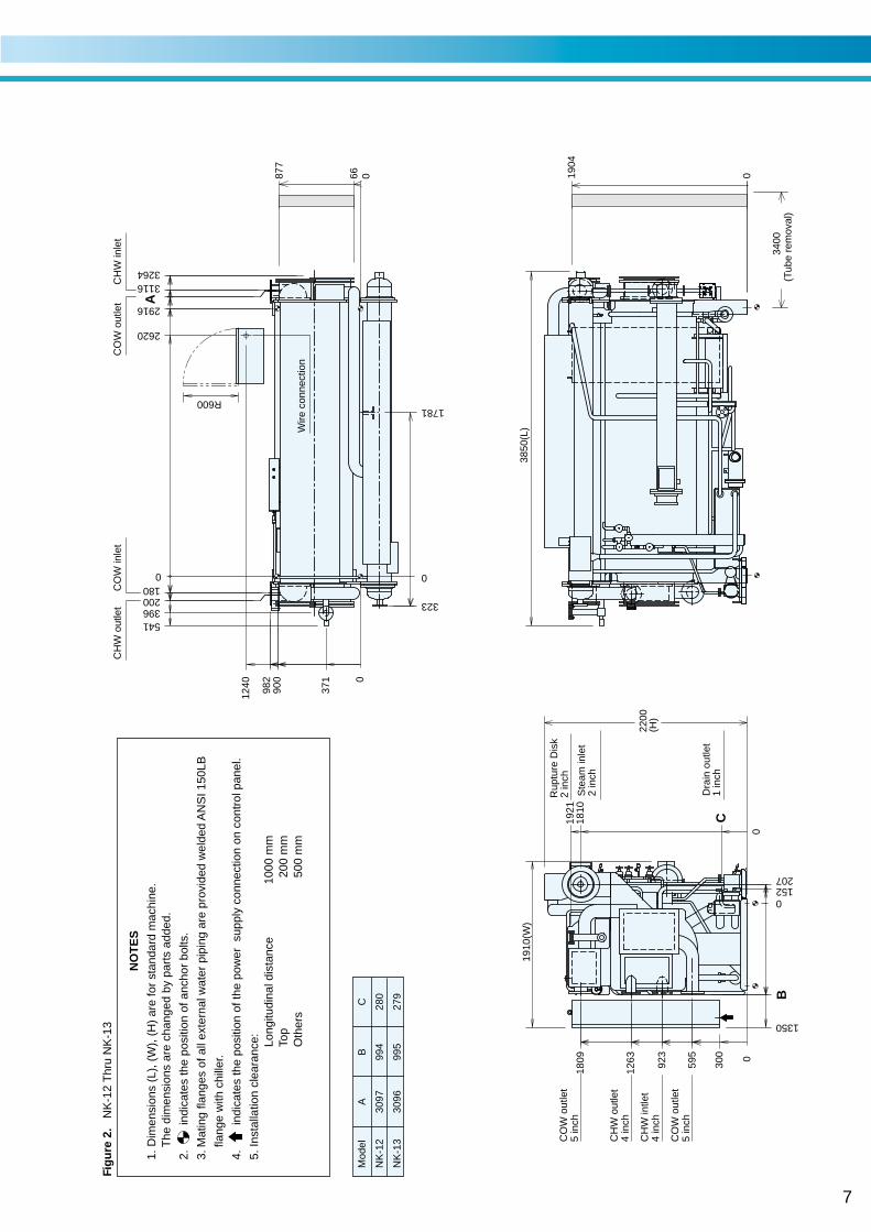
Mod
elA
BC
NK
-12
3097
994
280
NK
-13
3096
995
279
A
C
B
CO
W o
utle
t5
inch
CH
W o
utle
t4
inch
CO
W o
utle
t5
inch
CH
W in
tlet
4 in
ch
Fig
ure
2.
NK
-12
Thr
u N
K-1
3
N
OT
ES
1. D
imen
sion
s (L
), (
W),
(H
) ar
e fo
r st
anda
rd m
achi
ne.
The
dim
ensi
ons
are
chan
ged
by p
arts
add
ed.
2. in
dica
tes
the
posi
tion
of a
ncho
r bo
lts.
3.M
atin
g fla
nges
of a
ll ex
tern
al w
ater
pip
ing
are
prov
ided
wel
ded
AN
SI 1
50LB
flang
e w
ith c
hille
r.
4. in
dica
tes
the
posi
tion
of th
e po
wer
sup
ply
conn
ectio
n on
con
trol
pan
el.
5. In
stal
latio
n cl
eara
nce: Lo
ngitu
dina
l dis
tanc
e10
00 m
mTo
p20
0 m
mO
ther
s50
0 m
m
8
Dra
in o
utle
t
Ste
am in
let
Rup
ture
Dis
k2
inch
2 in
ch
1-1/
4 in
ch
CH
W o
utle
tC
HW
inle
tC
OW
inle
tC
OW
out
let
3400
(Tub
e re
mov
al)
Wire
con
nect
ion
0
1168
0
1006
1346
2159
0
205
265
1860
96
605
1980
2240
(W)
2131
300
1500
2250(H)
02089
3880
(L)
0
881003
0
0
1100
1165
212
312831112916
1950
323
1646
R600
568423
2620
430
1390
CO
W o
utle
t6
inch
CH
W o
utle
t5
inch
CO
W in
tlet
6 in
ch
CH
W in
tlet
5 in
ch
Fig
ure
3. N
K-2
1
N
OT
ES
1. D
imen
sion
s (L
), (
W),
(H
) ar
e fo
r st
anda
rd m
achi
ne.
The
dim
ensi
ons
are
chan
ged
by p
arts
add
ed.
2. in
dica
tes
the
posi
tion
of a
ncho
r bo
lts.
3.M
atin
g fla
nges
of a
ll ex
tern
al w
ater
pip
ing
are
prov
ided
wel
ded
AN
SI 1
50LB
flang
e w
ith c
hille
r.
4. in
dica
tes
the
posi
tion
of th
e po
wer
sup
ply
conn
ectio
n on
con
trol
pan
el.
5. In
stal
latio
n cl
eara
nce: Lo
ngitu
dina
l dis
tanc
e10
00 m
mTo
p20
0 m
mO
ther
s50
0 m
m
9
Dra
in o
utle
t
Ste
am in
let
Rup
ture
Dis
k2
inch
2-1/
2 in
ch
1-1/
4 in
ch
CH
W in
/out
let
CO
W in
let
CO
W o
utle
t
4500
(Tub
e re
mov
al)
Wire
con
nect
ion
CO
W o
utle
t8
inch
CH
W o
utle
t6
inch
CO
W in
tlet
8 in
ch
CH
W in
tlet
6 in
ch
0
0
605
1019
1333
2159
1980
0
20596
1840
1170
280
2070
(W)
2131
300
1500
2250(H)
02089
4920
(L)
881003
0
0
195225
3936
4131
4309
0
1100
1165
0
343
1899
423568
R600
3640
430
1390
Fig
ure
4. N
K-2
2
N
OT
ES
1. D
imen
sion
s (L
), (
W),
(H
) ar
e fo
r st
anda
rd m
achi
ne.
The
dim
ensi
ons
are
chan
ged
by p
arts
add
ed.
2. in
dica
tes
the
posi
tion
of a
ncho
r bo
lts.
3.M
atin
g fla
nges
of a
ll ex
tern
al w
ater
pip
ing
are
prov
ided
wel
ded
AN
SI 1
50LB
flang
e w
ith c
hille
r.
4. in
dica
tes
the
posi
tion
of th
e po
wer
sup
ply
conn
ectio
n on
con
trol
pan
el.
5. In
stal
latio
n cl
eara
nce: Lo
ngitu
dina
l dis
tanc
e10
00 m
mTo
p20
0 m
mO
ther
s50
0 m
m
10
CH
W in
let
CO
W in
let
CO
W o
utle
t
Dra
in o
utle
t
Ste
am in
let
Rup
ture
Dis
k3
inch in
ch
4500
(Tub
e re
mov
al)
Mod
elA
BC
DE
NK
-31
440
368
1855
2-1/
21-
1/4
NK
-32
460
370
1910
31-
1/2
C
A
B
D
inch
E
0
0
611
1066
1476
2198
0
2390
(H)
125218
251
2170
(W)
1256
1600
2298
02323
5040
(L)
0
245250492
3886
4131
4336
0
1200
1256
164
1078
0
0
2107
R 600
1490
3616
509
Wire
con
nect
ion
CO
W o
utle
t8
inch
CH
W o
utle
t6
inch
CO
W o
utle
t8
inch
CH
W in
tlet
6 in
ch
Fig
ure
5. N
K-3
1 T
hru
NK
-32
N
OT
ES
1. D
imen
sion
s (L
), (
W),
(H
) ar
e fo
r st
anda
rd m
achi
ne.
The
dim
ensi
ons
are
chan
ged
by p
arts
add
ed.
2. in
dica
tes
the
posi
tion
of a
ncho
r bo
lts.
3.M
atin
g fla
nges
of a
ll ex
tern
al w
ater
pip
ing
are
prov
ided
wel
ded
AN
SI 1
50LB
flang
e w
ith c
hille
r.
4. in
dica
tes
the
posi
tion
of th
e po
wer
sup
ply
conn
ectio
n on
con
trol
pan
el.
5. In
stal
latio
n cl
eara
nce: Lo
ngitu
dina
l dis
tanc
e10
00 m
mTo
p20
0 m
mO
ther
s50
0 m
m
11
CH
W in
let
CO
W in
let
CO
W o
utle
t
4500
(Tub
e re
mov
al)
Wire
con
nect
ion
0
0
0
577
1142
1613
12501321
335
2600
(H)
269
673
2035
2400
(W)
1675
2451
2383
02513
5100
(L)
00
244276492
3886
4130
4354
150
1132
0
1250
1321
0
407
1911
R 600
1565
3616
545
Dra
in o
utle
t
Ste
am in
let
Rup
ture
Dis
k3
inch
3 in
ch
1-1/
2 in
ch
CO
W o
utle
t10
inch
CH
W o
utle
t8
inch
CO
W o
utle
t10
inch
CH
W in
tlet
8 in
ch
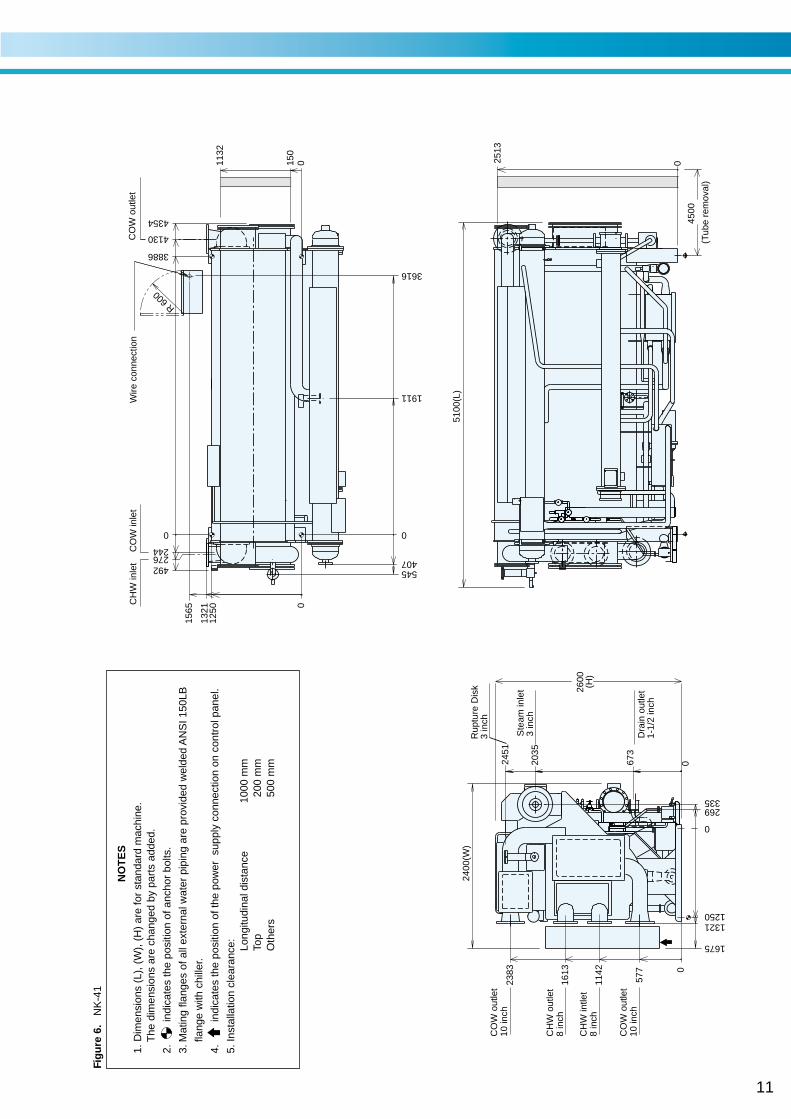
Fig
ure
6. N
K-4
1
N
OT
ES
1. D
imen
sion
s (L
), (
W),
(H
) ar
e fo
r st
anda
rd m
achi
ne.
The
dim
ensi
ons
are
chan
ged
by p
arts
add
ed.
2. in
dica
tes
the
posi
tion
of a
ncho
r bo
lts.
3.M
atin
g fla
nges
of a
ll ex
tern
al w
ater
pip
ing
are
prov
ided
wel
ded
AN
SI 1
50LB
flang
e w
ith c
hille
r.
4. in
dica
tes
the
posi
tion
of th
e po
wer
sup
ply
conn
ectio
n on
con
trol
pan
el.
5. In
stal
latio
n cl
eara
nce: Lo
ngitu
dina
l dis
tanc
e10
00 m
mTo
p20
0 m
mO
ther
s50
0 m
m
12
CH
W in
let
CO
W in
let
CO
W o
utle
t
4500
(Tub
e re
mov
al)
Wire
con
nect
ion
0
0
0
577
1142
1613
12501321
335
2600
(H)
269
673
2060
2400
(W)
1675
2451
2383
02513
5100
(L)
00
244276492
3886
4130
4354
150
1132
0
1250 399
1321
0
407
1911
R 600
1565
3616
545
Dra
in o
utle
t
Ste
am in
let
Rup
ture
Dis
k3
inch
3 in
ch
1-1/
2 in
ch
CO
W o
utle
t10
inch
CH
W o
utle
t8
inch
CO
W o
utle
t10
inch
CH
W in
tlet
8 in
ch
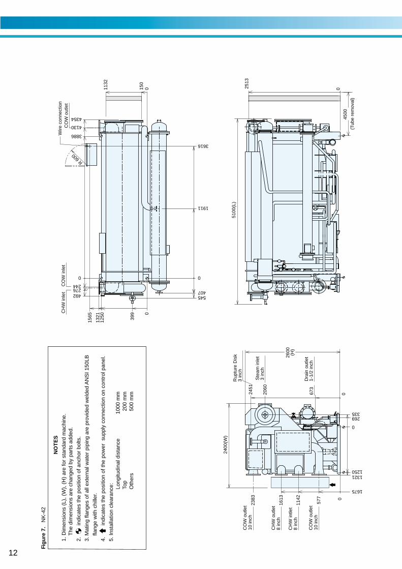
Fig
ure
7. N
K-4
2
N
OT
ES
1. D
imen
sion
s (L
), (
W),
(H
) ar
e fo
r st
anda
rd m
achi
ne.
The
dim
ensi
ons
are
chan
ged
by p
arts
add
ed.
2. in
dica
tes
the
posi
tion
of a
ncho
r bo
lts.
3.M
atin
g fla
nges
of a
ll ex
tern
al w
ater
pip
ing
are
prov
ided
wel
ded
AN
SI 1
50LB
flang
e w
ith c
hille
r.
4. in
dica
tes
the
posi
tion
of th
e po
wer
sup
ply
conn
ectio
n on
con
trol
pan
el.
5. In
stal
latio
n cl
eara
nce: Lo
ngitu
dina
l dis
tanc
e10
00 m
mTo
p20
0 m
mO
ther
s50
0 m
m
13
Rup
ture
Dis
k3
inch
4600
(Tub
e re
mov
al)
0
17001750
182
0
651
1170
1760
2630
02330
947
300
2770
(W)
2900(H)
221
2050
0
5330
(L)
2825
0
2909
265
24027
00
ST
EA
M in
let
3 in
chD
RA
IN o
utle
t 2
inch
0 570
1520
0
650
1940
0
367
CH
W o
utle
tC
OW
out
let
CH
W in
let/C
OW
inle
tW
ire c
onne
ctio
n
0
240265
130
38363966
4206
45824749
3280
R 800
CO
W o
utle
t12
inch
CH
W o
utle
t8
inch
CO
W o
utle
t12
inch
CH
W in
tlet
8 in
ch
Fig
ure
8. N
K-5
1
N
OT
ES
1. D
imen
sion
s (L
), (
W),
(H
) ar
e fo
r st
anda
rd m
achi
ne.
The
dim
ensi
ons
are
chan
ged
by p
arts
add
ed.
2. in
dica
tes
the
posi
tion
of a
ncho
r bo
lts.
3.M
atin
g fla
nges
of a
ll ex
tern
al w
ater
pip
ing
are
prov
ided
wel
ded
AN
SI 1
50LB
flang
e w
ith c
hille
r.
4. in
dica
tes
the
posi
tion
of th
e po
wer
sup
ply
conn
ectio
n on
con
trol
pan
el.
5. In
stal
latio
n cl
eara
nce: Lo
ngitu
dina
l dis
tanc
e10
00 m
mTo
p20
0 m
mO
ther
s50
0 m
m
14
(Tub
e re
mov
al)
0
17001750
182
0
651
1170
1760
2630
0947
300
2360
2800
(W)
221
2050
2900(H)
Rup
ture
Dis
k3i
nch
0
0
265
240
2825
2700
ST
EA
M in
let
4 in
chD
RA
IN o
utle
t 2
inch
CH
W in
let/o
utle
tC
OW
out
let
CO
W in
let
Wire
con
nect
ion
265
R 800
0
240
130
3380
1940 0
0
421
0 650
1520
650
AB
CD
E
F
HG
CO
W o
utle
t12
inch
CH
W o
utle
t8
inch
CO
W o
utle
t12
inch
CH
W in
tlet
8 in
ch
Fig
ure
9. N
K-5
2 T
hru
NK
-53
N
OT
ES
1. D
imen
sion
s (L
), (
W),
(H
) ar
e fo
r st
anda
rd m
achi
ne.
The
dim
ensi
ons
are
chan
ged
by p
arts
add
ed.
2. in
dica
tes
the
posi
tion
of a
ncho
r bo
lts.
3.M
atin
g fla
nges
of a
ll ex
tern
al w
ater
pip
ing
are
prov
ided
wel
ded
AN
SI 1
50LB
flang
e w
ith c
hille
r.
4. in
dica
tes
the
posi
tion
of th
e po
wer
sup
ply
conn
ectio
n on
con
trol
pan
el.
5. In
stal
latio
n cl
eara
nce: Lo
ngitu
dina
l dis
tanc
e10
00 m
mTo
p20
0 m
mO
ther
s50
0 m
m
Mod
elA
BC
DE
FG
H
NK
-52
4378
4508
4748
5123
5290
5870
5100
3451
NK
-53
4876
5006
5246
5622
5789
6370
5600
3949
15
(Tub
e re
mov
al)
CH
W o
utle
tC
HW
inle
tC
OW
out
let
CO
W in
let
Wire
con
nect
ion
0
751
1315
2025
3051 30
0
01067
2640
3330(H)
2970
(W)
0
250
1800
21501870
0
Rup
ture
Dis
k4i
nch
0
292
3264
310
6100
(L)
5200
3000
3260
CO
W o
utle
t14
inch
CH
W o
utle
t10
inch
CO
W o
utle
t14
inch
CH
W in
tlet
10 in
ch
ST
EA
M in
let 4
inch
DR
AIN
out
let
2 in
ch
0
4756
140
43284468
R 8
00
3260
292310
0
725
2040
0
441
52255392
0 715
1635
4760
250
Fig
ure
10. N
K-6
1
N
OT
ES
1. D
imen
sion
s (L
), (
W),
(H
) ar
e fo
r st
anda
rd m
achi
ne.
The
dim
ensi
ons
are
chan
ged
by p
arts
add
ed.
2. in
dica
tes
the
posi
tion
of a
ncho
r bo
lts.
3.M
atin
g fla
nges
of a
ll ex
tern
al w
ater
pip
ing
are
prov
ided
wel
ded
AN
SI 1
50LB
flang
e w
ith c
hille
r.
4. in
dica
tes
the
posi
tion
of th
e po
wer
sup
ply
conn
ectio
n on
con
trol
pan
el.
5. In
stal
latio
n cl
eara
nce: Lo
ngitu
dina
l dis
tanc
e10
00 m
mTo
p20
0 m
mO
ther
s50
0 m
m
16
CO
W o
utle
t14
inch
CH
W o
utle
t10
inch
CO
W o
utle
t14
inch
CH
W in
tlet
10 in
ch
Fig
ure
11. N
K-6
2
N
OT
ES
1. D
imen
sion
s (L
), (
W),
(H
) ar
e fo
r st
anda
rd m
achi
ne.
The
dim
ensi
ons
are
chan
ged
by p
arts
add
ed.
2. in
dica
tes
the
posi
tion
of a
ncho
r bo
lts.
3.M
atin
g fla
nges
of a
ll ex
tern
al w
ater
pip
ing
are
prov
ided
wel
ded
AN
SI 1
50LB
flang
e w
ith c
hille
r.
4. in
dica
tes
the
posi
tion
of th
e po
wer
sup
ply
conn
ectio
n on
con
trol
pan
el.
5. In
stal
latio
n cl
eara
nce: Lo
ngitu
dina
l dis
tanc
e10
00 m
mTo
p20
0 m
mO
ther
s50
0 m
m
0
2025
1315
753
3050
1870
0
1800
Ste
am in
let
5 in
ch
Dra
in o
utle
t2-
1/2
inch
2670
250
3330(H)
1545
725
575
3000
(W)
03260
0
432
762
(Tub
e re
mov
al)
Rup
ture
Dis
k4
inch
5700
450
6190
(L)
2565
5116
5430
5062
500
1635
0
CH
W in
/out
CO
W o
utC
OW
inle
tR
800
603
0
5395
3606
2090 0
140
46864826
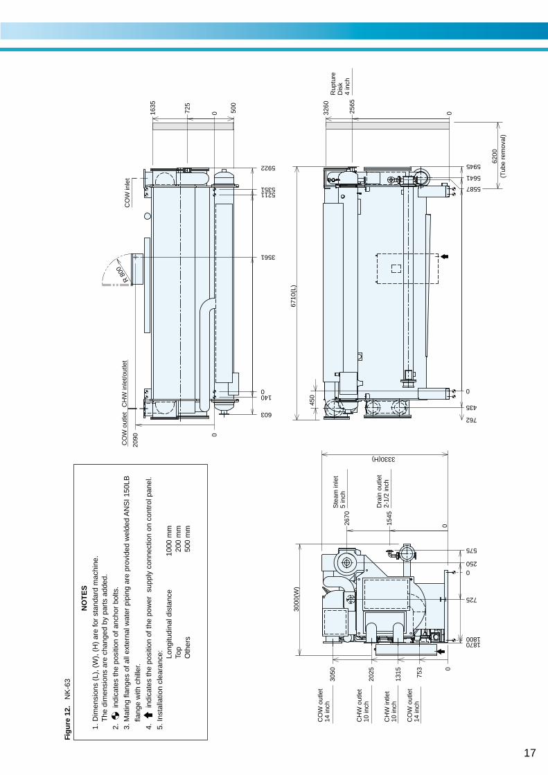
17
CO
W o
utle
t14
inch
CH
W o
utle
t10
inch
CO
W o
utle
t14
inch
CH
W in
tlet
10 in
ch
Fig
ure
12.
NK
-63
N
OT
ES
1. D
imen
sion
s (L
), (
W),
(H
) ar
e fo
r st
anda
rd m
achi
ne.
The
dim
ensi
ons
are
chan
ged
by p
arts
add
ed.
2. in
dica
tes
the
posi
tion
of a
ncho
r bo
lts.
3.M
atin
g fla
nges
of a
ll ex
tern
al w
ater
pip
ing
are
prov
ided
wel
ded
AN
SI 1
50LB
flang
e w
ith c
hille
r.
4. in
dica
tes
the
posi
tion
of th
e po
wer
sup
ply
conn
ectio
n on
con
trol
pan
el.
5. In
stal
latio
n cl
eara
nce: Lo
ngitu
dina
l dis
tanc
e10
00 m
mTo
p20
0 m
mO
ther
s50
0 m
m
0
2025
1315
753
3050
1870
0
1800
0
Ste
am in
let
5 in
ch
Dra
in o
utle
t2-
1/2
inch
3330(H)
2670
250
3000
(W)
1545
575
725
03260
0
435
762
Rup
ture
Dis
k4
inch
(Tub
e re
mov
al)
6200
450
6710
(L)
5945
5641
5587
2565
500
1635
0
R 8
00C
HW
inle
t/out
let
CO
W o
utle
tC
OW
inle
t
1400
603
52115351
5922
725
3561
2090 0
18
CO
W o
utle
t16
inch
CH
W o
utle
t12
inch
CO
W o
utle
t16
inch
CH
W in
tlet
12 in
ch
Fig
ure
13. N
K-7
1
N
OT
ES
1. D
imen
sion
s (L
), (
W),
(H
) ar
e fo
r st
anda
rd m
achi
ne.
The
dim
ensi
ons
are
chan
ged
by p
arts
add
ed.
2. in
dica
tes
the
posi
tion
of a
ncho
r bo
lts.
3.M
atin
g fla
nges
of a
ll ex
tern
al w
ater
pip
ing
are
prov
ided
wel
ded
AN
SI 1
50LB
flang
e w
ith c
hille
r.
4. in
dica
tes
the
posi
tion
of th
e po
wer
sup
ply
conn
ectio
n on
con
trol
pan
el.
5. In
stal
latio
n cl
eara
nce: Lo
ngitu
dina
l dis
tanc
e10
00 m
mTo
p20
0 m
mO
ther
s50
0 m
m
0
1960
1335
3135
2410
0
2200
1100
0
Ste
am in
let
6 in
ch
Dra
in o
utle
t2-
1/2
inch
3450(H)
2730
189
735
1563
3300
(W)
575
03370
0
430
44264286
850
1130
5300
(Tub
e re
mov
al)
6000
2613 0
4872
140
6440
(L)
02005
443
R 8
00
803
0
911
915 0
3861
2390
4956
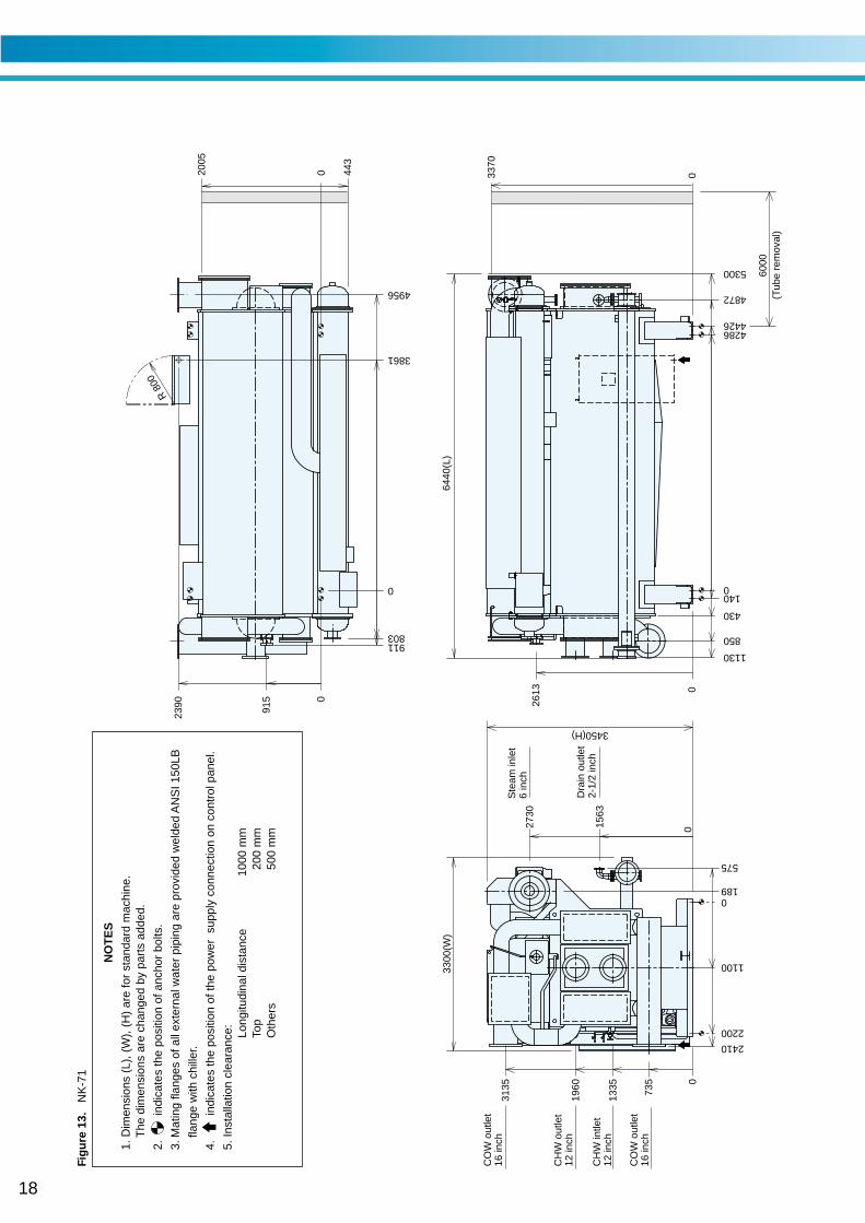
19
CO
W o
utle
t16
inch
CH
W o
utle
t12
inch
CO
W o
utle
t16
inch
CH
W in
tlet
12 in
ch
Fig
ure
14. N
K-7
2
N
OT
ES
1. D
imen
sion
s (L
), (
W),
(H
) ar
e fo
r st
anda
rd m
achi
ne.
The
dim
ensi
ons
are
chan
ged
by p
arts
add
ed.
2. in
dica
tes
the
posi
tion
of a
ncho
r bo
lts.
3.M
atin
g fla
nges
of a
ll ex
tern
al w
ater
pip
ing
are
prov
ided
wel
ded
AN
SI 1
50LB
flang
e w
ith c
hille
r.
4. in
dica
tes
the
posi
tion
of th
e po
wer
sup
ply
conn
ectio
n on
con
trol
pan
el.
5. In
stal
latio
n cl
eara
nce: Lo
ngitu
dina
l dis
tanc
e10
00 m
mTo
p20
0 m
mO
ther
s50
0 m
m
0
1960
1335
3050
2410
0
2200
1100
0
DR
AIN
out
let
2-1/
2 in
ch
ST
EA
M in
let
6 in
ch
3450(H)
2730
735
189
1563
3300
(W)
575
03370
0 140
430
5741
54515311
850
1130
6325
(Tub
e re
mov
al)
7000
7460
(L)
5897
2613 0
395
2055
0
R 8
00
803
0
3861
965
2440 0
5981
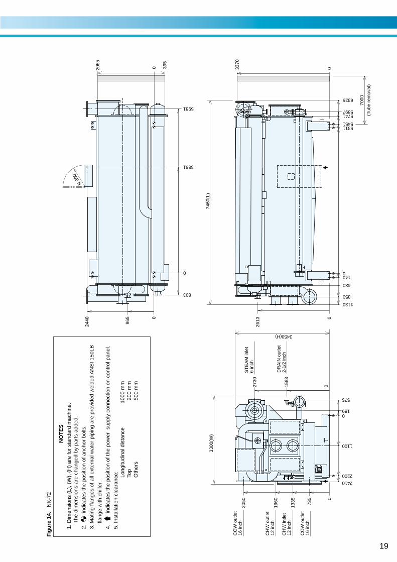
20
CO
W o
utle
t16
inch
CH
W o
utle
t14
inch
CO
W o
utle
t16
inch
CH
W in
tlet
14 in
ch
Fig
ure
15. N
K-8
1
N
OT
ES
1. D
imen
sion
s (L
), (
W),
(H
) ar
e fo
r st
anda
rd m
achi
ne.
The
dim
ensi
ons
are
chan
ged
by p
arts
add
ed.
2. in
dica
tes
the
posi
tion
of a
ncho
r bo
lts.
3.M
atin
g fla
nges
of a
ll ex
tern
al w
ater
pip
ing
are
prov
ided
wel
ded
AN
SI 1
50LB
flang
e w
ith c
hille
r.
4. in
dica
tes
the
posi
tion
of th
e po
wer
sup
ply
conn
ectio
n on
con
trol
pan
el.
5. In
stal
latio
n cl
eara
nce: Lo
ngitu
dina
l dis
tanc
e10
00 m
mTo
p20
0 m
mO
ther
s50
0 m
m
0
2040
1430
3330
2610
0
2400
146
1200
0
DR
AIN
out
let
3 in
ch
ST
EA
M in
let
6 in
ch
3650(H)
2900
757
1653
3500
(W)
575
03560
0 140
430
54515311
850
6323
1130
(Tub
e re
mov
al)
7000
5981
7460
(L)
5889
0
425
2185
0
R 8
00
830
0
3861
911
1000
2590 0
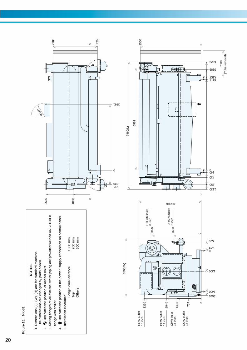
21
Foundation dimensional data (NK)
Figure 16. NK-11 Thru 61
150
A
JK
B B
D
C
EF
G I
AABB
Table 1. Dimensional data
NOTES :
1. The base of machine has ø50 hole for anchor bolt.2. Anchor bolt should be fixed by shown detail drawing.
Washer should be welded with base.3. There should be a drain ditch around the foundation.4. The floor surface should be made as water proof for ease of
maintenance work.5. Surface of foundation should be made flat.
(The levelness should be below 2mm for 1,000mm length.)6. Anchor bolts and nuts are supplied by customer.
NK-11 4,600 2,300 2,300 1,896 175 90 350 900 150 1,200 160 1,000 100 --NK-12 5,800 2,900 2,900 2,916 175 90 350 900 150 1,200 160 1,000 100 --NK-13 6,100 3,050 3,050 2,916 175 90 350 900 150 1,200 160 1,000 100 --NK-21 7,500 3,750 3,750 2,916 175 90 350 1,100 150 1,400 160 1,200 100 --NK-22 8,800 4,400 4,400 3,936 175 90 350 1,100 150 1,400 160 1,200 100 --NK-31 11,200 5,600 5,600 3,886 200 100 400 1,200 150 1,500 200 1,300 100 --NK-32 11,800 5,900 5,900 3,886 200 100 400 1,200 150 1,500 200 1,300 100 --NK-41 13,900 6,950 6,950 3,886 200 100 400 1,250 150 1,550 200 1,350 100 --NK-42 14,500 7,250 7,250 3,886 200 100 400 1,250 150 1,550 200 1,350 100 --NK-51 18,800 9,400 9,400 4,346 130 190 510 1,700 180 2,060 250 1,800 3,966 3,836NK-52 20,800 10,400 10,400 4,888 130 190 510 1,700 180 2,060 250 1,800 4,508 4,378NK-53 22,300 11,150 11,150 5,386 130 190 510 1,700 180 2,060 250 1,800 5,006 4,876NK-61 26,500 13,250 13,250 4,888 140 210 560 1,800 180 2,160 320 1,900 4,468 4,328NK-62 30,000 15,000 15,000 4,686 140 210 560 1,800 180 2,160 1,900 130 300 130NK-63 32,100 16,050 16,050 5,211 140 210 560 1,800 180 2,160 1,900 130 300 130NK-71 38,000 19,000 19,000 4,286 140 210 560 2,200 180 2,560 2,300 130 300 130NK-72 42,300 21,150 21,150 5,311 140 210 560 2,200 180 2,560 2,300 130 300 130NK-81 47,300 23,650 23,650 5,311 140 210 560 2,400 180 2,760 2,500 130 300 130
Model Weight (kg) Dimensions (mm)No. Oper. AA BB A B C D E F G H I J K
150
A
B B
D
H
EF
G
H
I
AABB
NK-11 to NK-42NK51 to NK-61
150
A
B BI
D
C K
J
EF
G H
AABB
NK-62 to NK-81
22
Control panel (NK)
Figure 17. Control panel
Table 2. Indication lamp
CHILLER
STOP RUN
SET BACK
#1ABS PUMP
#2ABS PUMP
REF PUMP
PURGE PUMP
SAFETY CIRCUIT
POWER
CHILLER ALARM
STAND BY
DILUTIONBUZZER STOP
OPERATIONSTOP RUN
REMOTE
LOCAL
1
6
11
12
4
5
2
3
7
9
10
8
Name Lamp color
Operation indication lamp Green
Stop indication lamp Orange
Alarm indication lamp Red
Remote/Local select key with lamp Green
Operation select key with lamp Green
Data display 7segment LED(Red)
Stand by indication lamp Green
Dilution indication lamp Green
Safety circuit indication lamp Green
Power indication lamp Orange
Data select key
Alarm buzzer stop key
Purge indication lamp Green
Purge pump on - off switch
symbol1
2
3
4
5
6
7
8
9
10
11
12
GL
43P
NK--11 thru NK--61600
A
GL43P
A
1600
300
190
80 80
Power supply∅ 35
Power supply∅ 22
Section A-A
Rubberpacking
23
Field wiring (NK)
Figure 18 Typical eA5lectrical field connection diagram - Hot water-fired (LJ)
358
359
FOR COOLING TOWER FANRUN/STOP SIGNAL
362
FOR DILUTION INDICATION
363
383
382
357
356
323
323
323
CH
52C
O52 COOLING WATER PUMP INTERLOCK
CHILLED WATER PUMP INTERLOCK120
170
FOR STOP INDICATION
350
335
334
E
345
346
342
340
341
0A
344
343
E
UL
L3
L2
L1
G
CE
1 4Y1 4Y
2 4Y1 4Y
2 4Y
Earthing resistance : Local regulation
thickness as the wire of the pow
er supply. )E
arthing cable : Annealed copper w
ire (Please use the w
ire as same the
And also connect w
ire between chiller control panel and earth at field.
The chiller has M
CB
. Please connect pow
er supply wire to the term
inal block.(1) W
iring of power supply and earthing
FIE
LD W
IRIN
G C
ON
NE
CT
ION
DC
24V 10m
A
PA
NE
LS
UP
PLIE
DF
IELD
CO
NT
RO
L PA
NE
L of CH
ILLER
FOR ALARM BUZZER
FOR STEAM SHUTOFF VALVE
FOR OPERATION INDICATION
FOR ALARM INDICATION
REMOTE CHECK SIGNAL
FOR COOLING WATER PUMPRUN/STOP SIGNAL
WATER PUMPFOR CHILLEDRUN/STOP SIGNAL
ANSWER BACK SIGNAL
PREALARM SIGNAL
COM
325
326
324
326
324
324
(3)pulse
326
325
170
170
326
325(2)pulse
324
170
326
351
353
352
337
336
369
368
348
347
355
354
361
360
121
170
(5)pulse
(1)continuous
(4)continuous
TE
RM
INA
L ST
RIP
S IN
TH
E C
ON
TR
OL P
AN
EL
DC
/AC
24VD
C/A
C 24V
324
RE
MO
TE
SIG
NA
L
(1)NO
N-V
oltage Norm
al open contact(a)for start & stop (D
C24V
10mA
). : W
iring the terminal 324 and 323, connect 170 and 326.
(2)NO
N-V
oltage Norm
al open contact(a)for start (DC
24V 10m
A).
: Wiring the term
inal 324 and 325, connect 170 and 326. N
ON
-Voltage N
ormal open contact(a)for stop (D
C24V
10mA
). : W
iring the terminal 325 and 323.
(3)NO
N-V
oltage Norm
al open contact(a)for start (DC
24V 10m
A).
: Wiring the term
inal 324 and 325, connect 170 and 326. N
ON
-Voltage N
ormal close contact(b)for stop (D
C24V
10mA
). : W
iring the terminal 325 and 323.
(4)Continuous signal of D
C/A
C 24V
for start & stop.(Initial S
etting) : W
iring the terminal 324 and 326. (T
hose terminals are non-polarity.)
(5)Pulse signal of D
C / A
C 24V
For start.
: Wiring the term
inal 324 and 326. (Those term
inals are non-polarity.) P
ulse signal of DC
/ AC
24V for stop.
: Wiring the term
inal 325 and 326. (Those term
inals are non-polarity.)
Chiller can be operated by the follow
ing five type signal.
TE
RM
INA
L ST
RIP
S IN
TH
E C
ON
TR
OL P
AN
EL
L3
L2
L1
PE
CE
: 3PH
50Hz 400V
UL : 3P
H 60H
z 208V, 460VT
O P
OW
ER
SO
UR
CE
CM
S(A
C24V
)
TG
2Y
31
OP
EN
CLO
SE
OP
EN
CLO
SE
PO
TI 135 O
HM
+--
CV
PD
C4-20m
A
CA
SE
OF
ST
EA
MC
ON
TR
OL V
ALV
E M
OT
OR
(FIE
LD S
UP
PLY
)
CA
SE
OF
ST
EA
MC
ON
TR
OL V
ALV
EP
OS
ITIO
NE
R(F
IELD
SU
PP
LY)
(1) Should be w
ork the electric wiring connection by license holder.
(2) Use steel conduit for electric w
iring between field electric supply and control panel of the chiller.
(3) Field w
iring connections are all low voltage w
ithout supply voltage.
24
General remarks on piping work
T : Thermometer
: Trap
P : Pressure gauge F : Flow meter : Water pump : Strainer : Valve : Valve : Thermostat
SteamShut-OFFValve
HC C
By-passvalve
SupplyHeader
ReturnHeader
Chilled waterPump(Primary)
Chilled waterPump(Secondary)
SteamControlValve
To Boiler
CoolingWater pump
Cooling waterThermostat
WaterSupply
SafetyValve
BleederValve
BypassVALVE
To Drain ditch
Reducing Valve
Main Steam Piping
CheckValve
R
In order to prevent freezing up of chilled water during diluting operation of the chiller, continue the operation of the chilled water pumps and air-conditioner until the diluting operatio will be completed.
MV
F
Air Conditioner
T
T
T
T
P
P
P
P
PP
Typical piping diagram (NK)
Figuare 19. Typical piping diagram
1. Work outside the area surrounded by this line shall have to be
executed at the expense of the owner.
2. Refer to the external dimensions diagrams and specification tables for
pipe connections and diameters.
3. Standard supply steam press. is 784kPa gauge. A reducing valve and
safety valve which blows at 980 kPa gauge should be located near the
machine as in above diagram if the supply pressure is higher than
784 kPa gauge.
A pipe should be extended from this safety valve to release excess
steam outdoor.
4. Even if a reducing valve is not required, a strainer, pressure gauge and
drain trap should be provided for each machine near the steam inlet.
5. The back pressure in the steam drain line should be limited to less
than 49kPa gauge.
6. Determine the locations of the chilled water pumps and cooling water
pumps in due consideration of the pump's hydrostatic head and lift.
The machine should not be subject to a pressure larger than 784 kPa
gauge at any water headers.
7. Concerning the temperature control of cooling water, refer to
"control method of cooling water temperature".
8. Provide a thermometer and a pressure gauge at the outlet and
inlet of cooling water and chilled water.
9. Provide an air vent in each of the chilled and cooling water line at
a point higher than the headers for chilled water and cooling water.
10. Lay pipe from the cover of the evaporator and absorber to the
drain ditch.
11. Provide a bleeder in the cooling water line for control of water
quality.
12. Be sure to provide the shut-off valve to prevent the steam flow into
the chiller during shut-down. and in case that two or more chillers
are installed, provide the automatic shut-off valve.
(The terminals sending open / close signal to steam shut-off valve
are furnished in control panel of the chiller.)
13. Be sure to design the location of cooling tower to prevent
contaminatin of cooling water by exhaust gas from flues.
25
Insulatuon (NK)
Figure 20. Insulation of NK
75 mm thick insulator for hot surfaces
50 mm thick insulator for hot surfaces
30 mm thick insulator for hot surfaces
50 mm thick insulator for cold surfaces
30 mm thick insulator for cold surfaces
Model 75mm 50mm 30mm 50mm 30mmTSA-NK-11TSA-NK-12TSA-NK-13TSA-NK-21TSA-NK-22TSA-NK-31TSA-NK-32TSA-NK-41TSA-NK-42TSA-NK-51TSA-NK-52TSA-NK-53TSA-NK-61
3.34.64.64.66.66.67.27.28.48.410.511.710.5
1.92.72.73.13.94.44.44.64.64.44.95.35.9
4.55.45.76.97.68.99.2
10.711.112.913.414.416.8
4.05.55.56.17.68.58.59.99.9
13.815.016.117.5
0.40.40.40.50.50.70.70.70.71.11.11.11.2
Hot surfaceinsulation(m2)
Cold surfaceinsulation(m2)
Evaporator Cover
Refrigerant pump
Do Not Cold InsulateThe Motor ofRefrigerant pump
Evaporator cover and high generator coverand high temperature heat reclaim coverare removal construction
High Generator Cover
High Temperature Haet Reclaim Cover
(SQ METER)
NOTICE
3. Use non-combustible insulation material.
1. The total area includes the area of pipes in the chiller.
2. The chiller / heater is coated with rust preventive before delivery,but is not provided with finish paint.
26
Rupture disk mounting
Mounting instructions of rupture disk1. Apply the teflon paste (Part code:814-2-3701-002-00)
to both sides of gasket slightly as shown in fig. 2In order to avoid leakage, don't apply too much teflon paste.
2. The gasket (Part code:814-2-2101-678-00-0 Should be used asindicated in FIG, 3.
3. Attach the upper flange exactly parallel to the lower flange.
4. A torque wrench should be used for tightening bolts equally and theappropriate torque is shown in fig.3 in disregard of the torquetable in the manufacture's installation instructions.Read the Manufacture's installation instructions before assembling.
5. Tighten up the bolts by a torque wrench in a periodical maintenance.6. The used gasket should not be applied again.7. Leak test should be conducted by bubble test.
Figure 21. Piping of rupture disk
3/16
1/8
2 inchdisk
3 inchdisk
4 inchdisk
A
B
C
(mm)
(mm)
(mm)
C B
A
Pipe
Pipe
Flange
Flange
High tension nut
High tension bolt
To tank
From chiller / heater
Teflon paste
Safety head
: Scope of supply by SANYO
Rupture disk
Safety head
Teflon paste
Gasket
Cap screw
Discharge piping
Rupture disk
Vent piping
Drain
Tank
Support
Chiller /Heater
Above 1m3
⋅ MATERIAL : T/#9090-OR⋅ ANSI CLASS 150 LBS⋅ PART NAME : PKG, GASKET FOR RUPTURE DISK⋅ PART CODE : 814-2-2101-675-00-0 : 2 INCH
814-2-2101-677-00-0 : 3 INC814-2-2101-678-00-0 ; 4 INCH
CAP SCREW
(HEXAGON SOCKET HEAD)
BOLTING CAP SCREWTORQUE (HEXAGON SOCKET HEAD)(N•m)
104.9
85.9
69.9
26
136.7
120.7
101.6
41
149.4
174.6
127.0
76
Absorption
27
Precautions for installation (NK)
1. Please keep local regulation at installation.
2. The chiller shall be installed in indoor.
3. Please install the chiller on the floor of heavy duty construction.
4. Please keep service maintenance space as shown dimensions drawing.5. Don´t install at many dust area.6. If necessary, please attach antivibrator.7. Please install control panel to avoid the direct rays of the sun. If the control panel is exposed to the direct rays of the sun,
it is difficult to show the display.8. Don´t install near exhaust gas port, deodorizer´s port and ventilation port.9. Please use the shackle, when the chiller is lift by wire.
In this case, please insert the shackle to the hole of the lower shell.10. Don´t fall down side-ways.11. Please keep delivery space for smooth installation.12. Take care the impact or fallen.13. In case of separate shipping, please assemble and weld by license holder. Please refer to the manuals.14. Should be work the electric wiring connection by license holder.15. Use steel conduit for electric wiring between field electric supply and control penel of the chiller.15. Use steel conduit for electric wiring between field electric supply and control panel of the chiller.16. Please connect the operation signal wires from the chiller to the chilled water pump and cooling water pump.
Each pump is operated by chiller signal automatically.Please connect interlock wire of each pump to the chiller.
17. In case of using remote signal, please don´t install at parallel with power line.18. Please connect earth line. Don´t connect the earth wire to gas pipe and water pipe, etc.19. Please wear the glasses and gloves when handling the solution.
Precautions for use (NK)
1. Installation and operation.Before installing and operating this chiller, you should read manual(s).
2. WARNING
Don´t store or use gasoline, thinner or other flammable vapors, liquids and materials in the vicinity of chiller.
3. Machine room.
Please keep the machine room temperature between 5°C(41°F) and 40°C(104°F), for protection of the solution crystalization during chiller shutdown.Please keep the humidity in the machine room whithin 90%.Please keep the service maintenance space as shown dimensions drawing.
4. Purging.Be sure not to leak the air into the chiller at any cases.(Refer to the manuals.)The chiller has Paladium cell for auto purge system, there for don´t turn off the main supply power to chiller during chiller shut down, too.
5. Pumps and Air hundling units.Operate the chilled water pump(s) and air handling unit(s) during dilution cycle operation of the chiller.During the chilld water pump(s) operation. never stop the cooling water pump(s) by manual.
6. Winter seasonIn winter, Don´t freeze the chilled and cooling waters in the pipe line during chiller shut down.When the cooling water pump(s) operate for freeze protection of cooling water, please operate chilled water pump(s) simultaneouly.
7. Service maintenanceIt is necessary to check on the chiller periodically.Please contact to service agent.
8. In case to give serious infliction by chiller´s trouble, please install stand by chiller.