wilmer fundus camera stimulator
TRANSCRIPT
Wilmer fundus camera stimulator
Janet S. Sunness, Mary A. Johnson, Robert W. Massof, and David L. Kays
The Wilmer fundus camera stimulator has been designed to allow testing of visual function at precise retinal
locations under direct visualization. We use a modified fundus camera with a deep red source and IR vidicon
to allow for both low levels of illumination and visualization of the fundus. The stimulus location is plotted
directly on a real-time digitized image of the fundus using computer-generated graphics, and fixation can be
monitored as testing proceeds. The fundus image with stimulus location can be stored on floppy disk for later
retrieval and analysis. Both static and kinetic perimetry can be performed. This paper describes the fundus
camera stimulator in detail, compares it to existing types of fundus perimeters, and provides clinical examples
of its use.
1. Introduction
It is often desirable, both for monitoring the courseof a retinal disease and for learning more about itspathophysiology, to be able to correlate a visual fielddefect with observable retinal pathology. This can beperformed only indirectly with conventional visualfield measures, since the patient's fixation may varyduring testing or be eccentric (as in the patient with acentral scotoma). Also borders of retinal lesions areoften irregular, and the irregularity may be difficult todetect or interpret using standard perimetric tech-niques. For these reasons, a number of researchershave focused attention on developing various types offundus perimeters-devices which provide a view ofthe fundus along with the location of the stimulus onthe fundus. Fundus perimeters are designed to pro-vide a direct correlation of visual function change withretinal lesions. There has been interest in performingthis sort of perimetry for many years, but perfection oftechniques has depended on gradual technological ad-vances. An ideal device would allow for visualizationof the stimulus on the fundus image, a range of differ-ent stimuli and visual function tests, and an objectivemeans of recording (or storing) the fundus image withstimulus location.
Early fundus perimeters used a direct ophthalmo-scope or Visuscope, with the fixation cross that is al-ready present in the apparatus serving as the target or
The authors are with Johns Hopkins Hospital, Wilmer Ophthal-mological Institute, Laboratory of Physiological Optics, Baltimore,
Maryland 21205.Received 14 August 1986.0003-6935/87/081487-05$02.00/0.© 1987 Optical Society of America.
with varying sized targets as stimuli.'-3 The first twostudies with this type of apparatus could detect onlynear-absolute scotomas. This technique providesuseful information, but the location of the stimulus hasto be recorded by hand on a fundus photograph. Kel-ley4 recommended using the 50-100-/im aiming beamof the argon laser photocoagulator (delivered througha slit lamp and fundus contact lens) as a stimulus forvisual field testing. The small size and precise local-ization of the aiming beam and the intense backgroundillumination allowed for identification and testing ofsmall retinal lesions. However, the brightness of thefield itself and the necessity for the aiming beam to beat threshold or higher for the observer limit the useful-ness of the test. Again, marking the stimulus locationon a fundus photograph had to be performed manuallyfollowing the test. These techniques have also beenused for measuring the focal electroretinogram andvisual evoked response under direct fundus visualiza-tion.5 -8
To deal with recording the fundus image and stimu-lus location directly, more recent attempts at fundusperimetry have utilized various types of fundus cam-era. Inatomi9 inserted a test object and a fixationpointer into a fundus camera and photographed thetest object location when patient responses were made.This technique was limited by the high illuminancelevels required by a conventional fundus camera.Isayama and Tagami10 attached a light stimulus sys-tem to an ordinary fundus camera and used a reticle tomap areas within 100 of the fovea. Although theyreduced the level of fundus illumination to allow for awider range of thresholds, the fundus could not bephotographed at this lower illuminance level whilemeasurements were being made.
To allow for a broader range of testing parameters,alternatives to the conventional fundus camera illumi-
15 April 1987 / Vol. 26, No. 8 / APPLIED OPTICS 1487

nation have been used. The major development hasbeen to use an IR fundus camera. Infrared illumina-tion permits low retinal illuminance levels while hav-ing sufficient irradiance to obtain a fundus image.The main technical difficulty has been documentingthe location of the stimulus, which is not visible on thefundus image. A variety of methods have been usedfor stimulus localization. Kani et al.11 initially em-ployed an IR cross surrounding the test object. Helater used a cathode ray tube in a plane conjugate tothe fundus, activated by a light pen pointed to an areaon the fundus image, to generate his test object.'2Stimulus location appears to have been recorded lateron the fundus image. Ohta et al.13 used a prototype ofthe Canon fundus photoperimeter, an IR fundus cam-era which locates the stimuli by punching holes on arecording card in a plane conjugate to the fundus.When testing is completed, the examiner photographsthe fundus with the superimposed stimulus marks.The Canon fundus photoperimeter has also been usedby Enoch et al.'4 in their studies of gyrate atrophy.The disadvantage of this method is that since there isno guarantee that the subject's fixation remains stablethroughout the testing session, the punched holes mayno longer correspond to the retinal location testedwhen they are superimposed on the fundus photo-graph. Two problems inherent in IR fundus peri-metry are the emphasis of choroidal over retinal fea-tures and the fact that some retinal lesions may changesubstantially or even disappear under IR illumina-tion.' 5" 6
The scanning laser ophthalmoscope'7 illuminatesthe retina with a raster pattern formed by a laser beamand provides a potential for generating a wide varietyof test patterns and producing a crisp fundus image.It originally employed small spots of light as stimuli,'8but it can also use patterned stimuli (such as letters)' 9
and has recently been used for layer-by-layer peri-metry.20 To date, however, it still requires high illu-minance levels for forming images (0.1 mW/cm 2 or-4.4 X 10⁻⁴ lm/mm2), although nowhere near levels forconventional fundus photography. Also, data acquisi-tion is accomplished by videotaping the test session,making later analysis of the experimental results labo-rious. The scanning laser ophthalmoscope is beingupgraded, and these limitations will probably be re-solved in future models of the instrument.
We have developed and now routinely use a funduscamera stimulator designed to overcome many of thelimitations in other methods of fundus perimetry asdetailed above. We used this system to examine anumber of different types of retinal pathology. In thispaper, we describe the fundus camera stimulator indetail, provide clinical examples of its use, and com-pare it with other existing forms of fundus perimetry.
II. Methods
We employ a Zeiss (300) fundus camera, which ismodified in several ways. The ocular and 35-mm cam-era mount are replaced by an IR-sensitive video cam-era (TC1005/HO1 RCA 4532H low bloom silicon target
vidicon) and a stimulus port of our design. A fixationpointer, consisting of a thin rod with a hollow enlargedcircular tip containing two cross hairs, is positioned ina plane conjugate to the retina. Fundus illuminationis reduced to scotopic levels by a deep red cutoff filter(Wratten filter 87) in front of the standard funduscamera tungsten light source. The reflected lightfrom the fundus is transmitted to the video camera viaa dichroic filter (OCLI 450 red). The measured retinalilluminance from the background is 50 photopic Td(1.8 X 10⁻⁷ lm/mm 2 ), considerably less than the levelused for conventional fundus photography (10 mW/cm2 or -6.5 X 10⁻² lm/mm 2 ).2' This level of illumina-tion permits us to measure thresholds in scotopic con-ditions.
The output of the video camera is connected to anOCULUS 2000 digitizing board mounted in a Compaqcomputer. The fundus image is digitized (resolutionof 512 X 512 pixels, 128 gray levels), and the digitizedimage is displayed in real time on a high-resolutionvideo monitor. The OCULUS system is able to grab(freeze) a frame, perform simple image enhancement,and save the digitized image on floppy disk for laterretrieval and analysis.
We are presently using an achromatic stimulus thatis transmitted by a single fiber of a fiber optic. Theend of the fiber, subtending a visual angle of 30 min,serves as the stimulus and is positioned in the funduscamera stimulus port in a plane conjugate to the retina.The maximum (i.e., unfiltered) retinal illuminance ofthe stimulus is 6000 photopic Td. The stimulus maybe positioned anywhere in the field by means of x and ypositioners. The xy position of the stimulus is record-ed by linear potentiometers connected to analog-to-digital (A-D) converters in the computer. Both thefundus image plane in which the stimulus is locatedand the fundus image plane utilized by the video cam-era are past the optics of the fundus camera, so therelationship between the two images remains un-changed regardless of the eye's optics or magnificationutilized by the fundus camera. Since the stimulus isnot visible on the video image, it was necessary to use acomputer-generated cursor to show the stimulus posi-tion on the fundus image displayed on the monitor.
To calculate the placement of this stimulus cursor, itwas necessary to correlate the xy position of the stimu-lus as measured by the linear potentiometers with thex,y position of the stimulus on the fundus video image.The following technique was employed to establish therelationship between the A-D values and the true x,yposition on the fundus image. The x and y A-D valueswere sampled at equally spaced intervals for a total of100 sample points. These points spanned the fullfundus image available for stimulus presentation.With the stimulus on continuously, a normal subjectmoved the fixation pointer so that the center of thecross hairs was directly over the stimulus. The circu-lar ring of the pointer was visible on the fundus imageviewed by the experimenter on the video monitor andusing a joystick as cursor was positioned directly overthe center of the circular ring on the fundus image.
1488 APPLIED OPTICS / Vol. 26, No. 8 / 15 April 1987

The computer stored the x,y coordinates for the digitalimage display and the A-D values for each samplepoint. This procedure was repeated for each stimulusposition. A multiple regression analysis was then per-formed, giving linear equations for the x,y image coor-dinates as a function of the xy stimulus coordinates.(There was a slight rotation of the video camera rela-tive to the x,y positioner, so that the x image coordi-nate was a function of the x and y stimulus positioncoordinates and similarly for the y image coordinate.)
To determine the accuracy of this mapping, fivenormal observers performed the same matches at elev-en selected points. We found a mean difference be-tween each observer's match and the predicted stimu-lus location to be 4.5 pixels (-20 min of arc) within thecentral 150 of the field and 6.2 pixels in the moreperipheral areas. There was no bias in this error; thatis, there was no systematic deviation. This suggeststhat the error may be accounted for by variability inplacement of the pointer by the observers and in local-ization of the center of the pointer on the image by theexperimenter. The somewhat larger error in the pe-ripheral field may be due to nonlinear magnification.
The testing session proceeds as follows: The sub-ject's pupil is dilated with 1% tropicamide; pupillarydilatation is sometimes unnecessary if the annulus oflight fits in the undilated pupil. The subject's eye isthen patched to dark-adapt for 45 min. The subject'shead is stabilized by using a dental impression bite barand a forehead rest. The fundus camera is focused toobtain the sharpest image of the fundus on the videomonitor. The fixation pointer is positioned so that theretinal area of interest is included in the fundus image.The pointer is generally positioned so as to allow a viewof optic nerve head (disk) detail and emanating retinalvasculature. This helps in monitoring the subject'salignment (as described below) and in later registeringthe IR fundus image with a conventional color fundusimage. At this point we have the option (generally notrequired) of enhancing contrast by adjusting the look-up tables for displaying gray levels.
The next step is to place alignment marks on thefundus image. When the subject has established astable pattern of fixation, we grab a frame and allowthe subject to relax. Using a joystick, we place com-puter-generated spots at positions on the image tomark major fundus features. These features includethe margins of the disk, vessel bifurcations or changesin direction, and any fundus features unique to thatsubject such as pigment, scars, or atrophy. Once com-pleted, the alignment coordinates are stored, alongwith the subject's name and other information, onfloppy disk. Storing alignment marks facilitates re-testing the patient in the future, since with properplacement of the fixation stimulus the x,y location oftested features would then correspond between ses-sions. These initial procedures of positioning the sub-ject, enhancing contrast, and placing alignment markstake 5 min or less.
To begin threshold testing, the subject returns to hisaligned position, and a frame is grabbed. The stimu-
lus is moved until it is at the desired location on thefundus image. The stimulus location is marked bycomputer graphics, and the display returns to realtime. Static thresholds are obtained using a methodof ascending and descending limits. We have a rangeof 4.5 log units in 0.1-log unit steps. The experimenterwatches the fundus image and alignment marks toensure that the stimulus is at the desired retinal loca-tion. When ready, the experimenter presses a key onthe computer and three things occur: A bell rings,alerting the subject to stimulus presentation, a shutteris opened for 500 ms to display the stimulus, and aframe is grabbed documenting the precise location ofthe stimulus on the fundus at the time of stimuluspresentation. The subject signals with a buzzer if hehas seen the stimulus, and stimulus luminance levelsare adjusted accordingly. The image returns to realtime, and the operator again triggers a presentation inthe same manner until the threshold at the given stim-ulus location is obtained. If a variation in fixation isnoted during presentation, that particular trial is re-jected.
The experimenter positions a landmark referencecursor at a prominent retinal landmark, such as avessel bifurcation, so that its position each time will beeasily and accurately determined. The purpose of thislandmark is to allow us to superimpose all data pointsonto one fundus image at the conclusion of the session,and we can thus correct for position errors owing tofixation changes during the session. The experiment-er may then save the image on floppy disk. Tworeticles are positioned to define the rectangular area ofthe image to be saved. Since saving a full buffer-sizedimage onto floppy disk takes -1.5 min, we generallylimit the number of images saved. If we are testing at aspecific location, for example over a visible retinallesion or near it, we generally save a portion of theimage. However, if we are testing at a given eccentrici-ty to establish a baseline and are not critically con-cerned with precise location of the stimulus, we maysave only the coordinates of the data point, the land-mark reference cursor, and the filter value, and not theimage itself.
The monitor returns to a real-time image, and theexperimenters are ready to test a new location. Theactual testing at each location requires only 1-2 min,and data storage, including saving the image, takes -3min. A total of ten points is the average number testedper session, but considerably more points can be testedif necessary, limited by patient fatigue. In our studyof age-related macular degeneration, we tested overtwenty patients in the age range of 60-85 yr withoutundue difficulty.
The fundus camera stimulator can also be used toperform kinetic perimetry. In this case, the shutter isplaced in an open position, a given filter level is select-ed, the stimulus is moved manually via the x and ypositioners, and the stimulus location on the fundusimage is monitored as the subject reports when he seesor does not see the light. Information acquired usingthe fundus camera stimulator for kinetic perimetry
15 April 1987 / Vol. 26, No. 8 / APPLIED OPTICS 1489
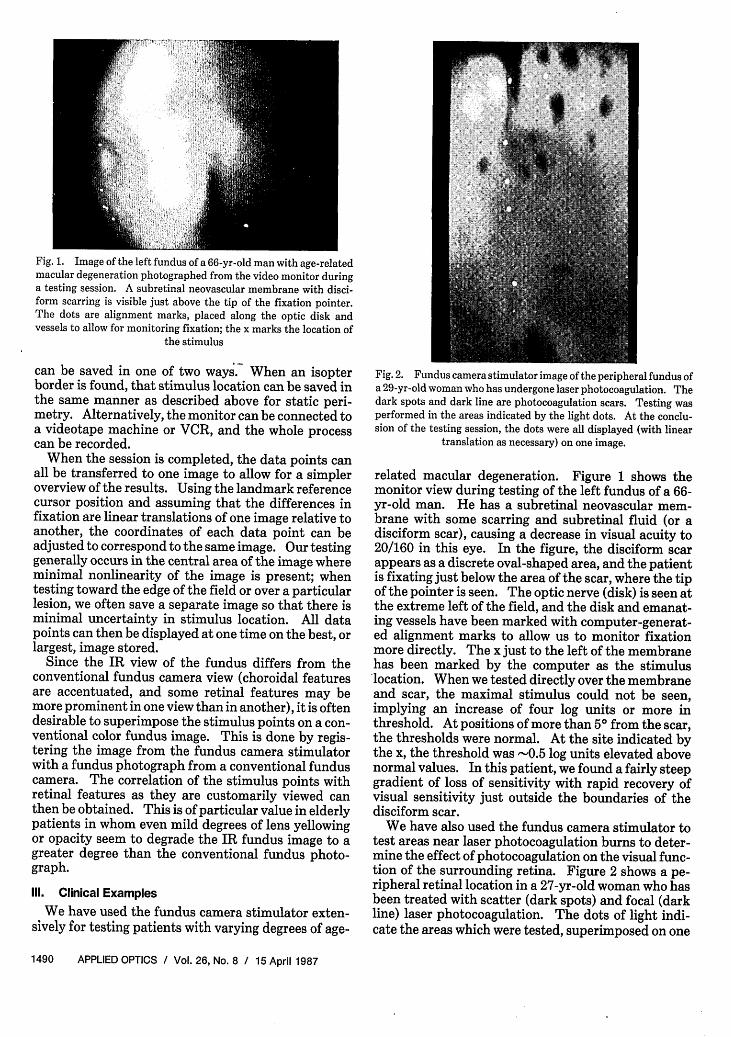
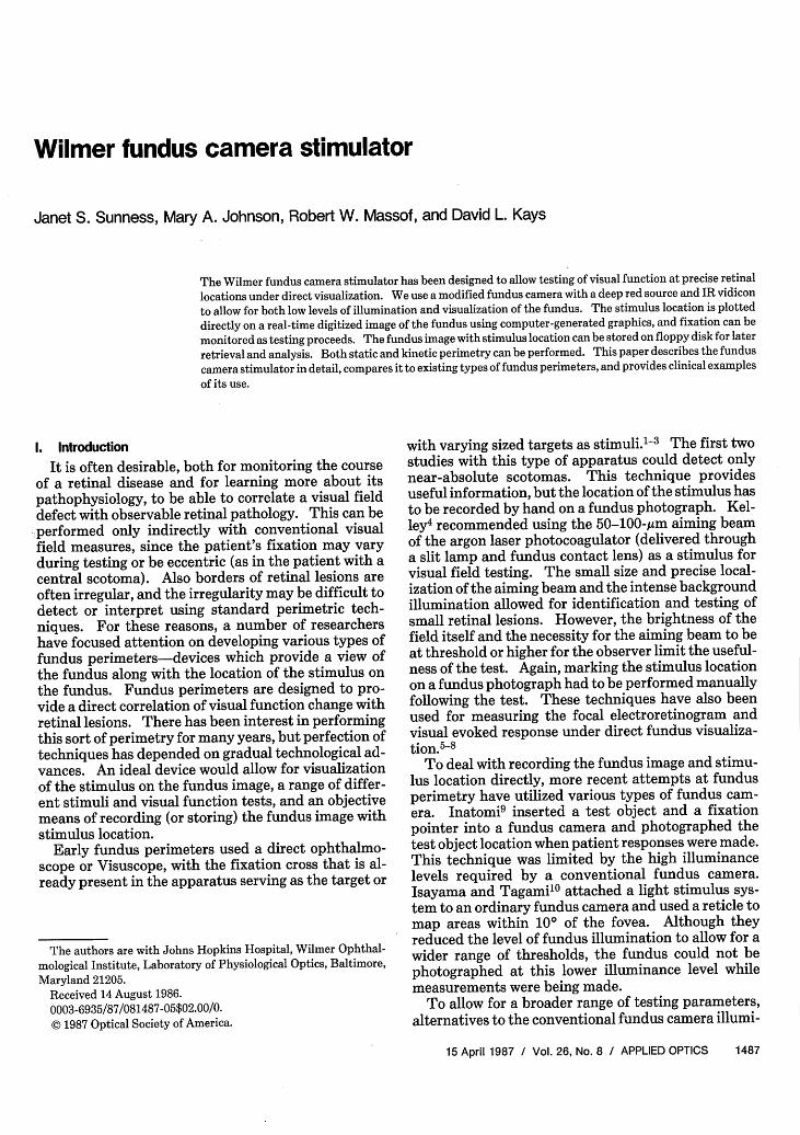
Fig. 1. Image of the left fundus of a 66-yr-old man with age-relatedmacular degeneration photographed from the video monitor duringa testing session. A subretinal neovascular membrane with disci-form scarring is visible just above the tip of the fixation pointer.The dots are alignment marks, placed along the optic disk andvessels to allow for monitoring fixation; the x marks the location of
the stimulus
can be saved in one of two ways. When an isopterborder is found, that stimulus location can be saved inthe same manner as described above for static peri-metry. Alternatively, the monitor can be connected toa videotape machine or VCR, and the whole processcan be recorded.
When the session is completed, the data points canall be transferred to one image to allow for a simpleroverview of the results. Using the landmark referencecursor position and assuming that the differences infixation are linear translations of one image relative toanother, the coordinates of each data point can beadjusted to correspond to the same image. Our testinggenerally occurs in the central area of the image whereminimal nonlinearity of the image is present; whentesting toward the edge of the field or over a particularlesion, we often save a separate image so that there isminimal uncertainty in stimulus location. All datapoints can then be displayed at one time on the best, orlargest, image stored.
Since the IR view of the fundus differs from theconventional fundus camera view (choroidal featuresare accentuated, and some retinal features may bemore prominent in one view than in another), it is oftendesirable to superimpose the stimulus points on a con-ventional color fundus image. This is done by regis-tering the image from the fundus camera stimulatorwith a fundus photograph from a conventional funduscamera. The correlation of the stimulus points withretinal features as they are customarily viewed canthen be obtained. This is of particular value in elderlypatients in whom even mild degrees of lens yellowingor opacity seem to degrade the IR fundus image to agreater degree than the conventional fundus photo-graph.
Ill. Clinical Examples
We have used the fundus camera stimulator exten-sively for testing patients with varying degrees of age-
Fig. 2. Fundus camera stimulator image of the peripheral fundus ofa 29-yr-old woman who has undergone laser photocoagulation. Thedark spots and dark line are photocoagulation scars. Testing wasperformed in the areas indicated by the light dots. At the conclu-sion of the testing session, the dots were all displayed (with linear
translation as necessary) on one image.
related macular degeneration. Figure 1 shows themonitor view during testing of the left fundus of a 66-yr-old man. He has a subretinal neovascular mem-brane with some scarring and subretinal fluid (or adisciform scar), causing a decrease in visual acuity to20/160 in this eye. In the figure, the disciform scarappears as a discrete oval-shaped area, and the patientis fixating just below the area of the scar, where the tipof the pointer is seen. The optic nerve (disk) is seen atthe extreme left of the field, and the disk and emanat-ing vessels have been marked with computer-generat-ed alignment marks to allow us to monitor fixationmore directly. The x just to the left of the membranehas been marked by the computer as the stimuluslocation. When we tested directly over the membraneand scar, the maximal stimulus could not be seen,implying an increase of four log units or more inthreshold. At positions of more than 5 from the scar,the thresholds were normal. At the site indicated bythe x, the threshold was -0.5 log units elevated abovenormal values. In this patient, we found a fairly steepgradient of loss of sensitivity with rapid recovery ofvisual sensitivity just outside the boundaries of thedisciform scar.
We have also used the fundus camera stimulator totest areas near laser photocoagulation burns to deter-mine the effect of photocoagulation on the visual func-tion of the surrounding retina. Figure 2 shows a pe-ripheral retinal location in a 27-yr-old woman who hasbeen treated with scatter (dark spots) and focal (darkline) laser photocoagulation. The dots of light indi-cate the areas which were tested, superimposed on one
1490 APPLIED OPTICS / Vol. 26, No. 8 / 15 April 1987
image in the manner described above. We found thatthe patient could not detect the maximal stimuluswhen we tested directly over a laser scar. In nearbyareas and areas between laser scars, the sensitivity wasthe same as in corresponding areas of an untreatedperipheral retina. Thus, as measured by this tech-nique, laser photocoagulation did not affect thresholdsof neighboring retina.
IV. Summary
We have developed the fundus camera stimulator toallow us to test visual function at precise retinal loca-tions. We use a modified conventional fundus camerawith IR sensing vidicon and deep red light as ourbackground to allow for very low levels of illuminationand scotopic testing conditions. The fundus image isdisplayed on a high-resolution video monitor, and thestimulus location is plotted directly on the fundusimage using computer-generated graphics. Using adigitizing board and frame-grabbing system, we freezea frame at the moment a stimulus is presented allowingfor precise knowledge of fixation and stimulus loca-tion. Our test session can be videotaped, or our fun-dus images can be stored directly on floppy disk, forlater retrieval and analysis. Our IR photos can beregistered with conventional fundus photographs.Further modifications of our design will allow us toexpand our range of stimuli, employ patterned stimulias well, and use different types of background illumi-nation to overcome problems with image quality. Inits present state, we have found the fundus camerastimulator useful for examining a wide variety of reti-nal disorders and for learning more about their effectson visual function.
This study was supported in part by research grantEY-05675, Physician Scientist Award EY-00259 (J. S.Sunness), and core facility grant EY-01765 from theNational Eye Institute, National Institutes of Health,Bethesda, MD.
Aspects of this paper were presented in a postersession at the 1985 OSA Annual Meeting.
References
1. N. G. Trantas, "Applications et resultats d'un moyen simpled'examen de la photosensibilite de la retine," Bull. Soc. Oph-
thalmol. Fr. 55, 499 (1955).2. M. P. Meyers, "The Use of the Visuscope for Mapping a'Field' of
Retinal Function," Am. J. Ophthalmol. 47, 677 (1959).3. S. Awaya, T. Ohashi, and T. Asano, "Spot Scotometry-a New
Method to Examine Scotomas under Direct Ophthalmoscopy byUsing Visuscope (Euthyscope)," Jpn. J. Ophthalmol. 16, 144
(1972).4. J. S. Kelley, "Use of the Argon Aiming Beam in Visual Function
Testing," Ann. Ophthalmol. 10, 1687 (1978).5. J. Inoue, K. Takeo, and T. Akiba, "The Visual Evoked Poten-
tials to Focal Illumination of the Retina by Direct View Oph-thalmoscopy," Acta Soc. Ophthalmol. Jpn. 77, 1149 (1973).
6. M. A. Sandberg and M. Ariel, "A Hand-Held, Two-ChannelStimulator-Ophthalmoscope," Arch. Ophthalmol. 95, 1881
(1977).7. T. Shipley, "The Visually Evoked Occipitogram in Strabismic
Amblyopia under Direct-View Ophthalmoscopy," J. Pediatr.Ophthalmol. 6, 97 (1969).
8. T. Hirose, Y. Miyake, and A. Hara, "Simultaneous Recording of
Electroretinogram and Visual Evoked Response," Arch. Oph-thalmol. 95, 1205 (1977).
9. A. Inatomi, "A Simple Fundus Perimetry with Fundus Camera,"Doc. Ophthalmol. Proc. Ser. 19, 359 (1979).
10. Y. Isayama and Y. Tagami, "Quantitative Maculometry Using aNew Instrument in Cases of Optic Neuropathies," Doc. Oph-
thalmol. Proc. Ser. 14, 237 (1977).11. K. Kani, N. Eno, K. Abe, and T. Ono, "Perimetry under Televi-
sion Ophthalmoscopy," Doc. Ophthalmol. Proc. Ser. 14, 231
(1977).12. K. Kani and Y. Ogita, "Fundus Controlled Perimetry," Doc.
Ophthalmol. Proc. Ser. 19, 341 (1979).13. Y. Ohta, T. Miyamoto, and K. Harasawa, "Experimental Fun-
dus Photo Perimeter and Its Application," Doc. Ophthalmol.Proc. Ser. 19, 351 (1979).
14. J. M. Enoch, J. O'Donnell, R. A. Williams, and E. A. Essock,
"Retinal Boundaries and Visual Function in Gyrate Atrophy,"Arch. Ophthalmol. 102, 1314 (1984).
15. A. P. Cullen, "Fundus Examination with Restricted SpectrumLight," Am. J. Optom. 48, 803 (1971).
16. F. C. Delori, E. S. Gragoudas, R. Francisco, and R. C. Pruett,
"Monochromatic Ophthalmoscopy and Fundus Photography,"Arch. Ophthalmol. 95, 861 (1977).
17. R. H. Webb, G. W. Hughes, and 0. Pomerantzeff, "Flying Spot
TV Ophthalmoscope," Appl. Opt. 19, 2991 (1980).18. G. T. Timberlake, M. A. Mainster, R. H. Webb, G. W. Hughes,
and C. L. Trempe, "Retinal Localization of Scotomata by Scan-ning Laser Ophthalmoscopy," Invest. Ophthalmol. Vis. Sci. 22,
91 (1982).19. M. A. Mainster, G. T. Timberlake, R. H. Webb, and G. W.
Hughes, "Scanning Laser Ophthalmoscopy," Ophthalmology89, 852 (1982).
20. R. H. Webb, E. A. Essock, J. M. Enoch, and R. A. Williams,"Measurement of Layer-by-Layer Perimetry Responses UsingDirect Retinal Projection by the Scanning Laser Ophthalmo-scope," in Proceedings, Sixth International Visual Field Sym-posium, A. Heijl and E. L. Greve, Eds. (Dr. W. Junk, Dordrecht,The Netherlands, 1985), pp 481-486.
21. F. C. Delori, J. S. Parker, and M. A. Mainster, "Light Levels inFundus Photography and Fluorescein Angiography," VisionRes. 20, 1099 (1980).
15 April 1987 / Vol. 26, No. 8 / APPLIED OPTICS 1491