· web viewone pixel contains r, g, and b color that each can achieve 256 level brightness...
TRANSCRIPT

Side View LED IC
ISD4516VGBC1MAK3
◆Outline (L* W*H): 4.5*1.6*1.7mm◆Good thermal dissipation & optical uniformity
Table of ContentsProduct Code Method -----------------------------------------2
Maximum Rating ----------------------------------------------2
Typical Product Characteristics------------------------------3
Electrical Characteristics -------------------------------------3
Range of Bins---------------------------------------------------4
Color Coordinate Comparison -------------------------------4
Function description ----------------------------------------5-6
Dimensions -----------------------------------------------------7
PIN Configuration -------------------------------------------8
Reflow Profile ------------------------------------------------9
Test Circuit and Handling Precautions ----------------------10
Packing--------------------------------------------------------11-12
Precautions -----------------------------------------------------13
Features RoHS Compliant
Packaged in 12mm tape on 7" diameter reels
EIA STD package
Compatible with automatic placement equipment
and infrared reflow solder process
Preconditioning: accelerate to JEDEC level 3
Serial data transmission signal by(DATA CLK) two line
One pixel contains R, G, and B color that each can
achieve 256 level brightness grayscale, which
forms 16, 777, 216combination colors.
Supports sleep /wake-up mode. In sleep mode, the
LED's current was lower than 5uA.
.
Applications Telecommunication, office automation, home
appliances, industrial equipment
Status indicator
Signal and symbol luminaire
Front panel backlighting
Full-color strip.
Indoor decorative lighting / curtain display
Version: IS-1.0 BT-SMD-190826001 Page 1 of 13

Side View LED IC
Product Code Method-----------------------------------------------------------------------------------------------------------------------------------
I - S - D - 4516- VGBC - 1 - M - A – K3① ② ③ ④ ⑤ ⑥ ⑦ ⑧ ⑨
① ② ③ ④ ⑤Process Type Category LED Type Lead Frame Size
Dice wavelength& luminous rank
I: With IC Series S: SMD LEDC: PLCC top view
D: PLCC side view
4516:
4.5*1.6mm
V:red
G:green
B:blue
C:IC
⑥ ⑦ ⑧ ⑨
Lap Polarity Cap Color PCB Module Code Flow Code
1: common anode M: white diffused A article mode:K: sleep mold IC 102
3: 20mA
Maximum Rating(Ta=25 )℃------------------------------------------------------------------------------------------------------------------------------------
Parameter Symbol Rating Unit
IC Power Supply Voltage VDD < 6.5 V
LED voltage V led 4.5-5.5 V
Rate of data signal FCLK 15 MHZ
The max led output Current IOMAX 20 / channel mA
Power dissipation; PD <400 mW
Soldering Temperature*1 TSD 260 o C
Operating Temperature Range -40 to+85℃ ℃
Storage Temperature Range -40 to+105℃ ℃
Version: IS-1.0 BT-SMD-190826001 Page 2 of 13

Side View LED IC
Typical Product Characteristics(Ta=25 )℃------------------------------------------------------------------------------------------------------------------------------------
Characteristics Symbol Min. Typ. Max. Unit Test condition
Luminous Intensity Iv
R 370
mcd IF=20mAG 1000
B 230
W 1450
Dominant Wavelength λd
R 615 - 630
nm IF=20mAG 520 - 530
B 460 - 475
Color Coordinatex - 0.2735 - -
IF=20mAy - 0.2728 - -
View Angle 2θ1/2 - 120 - deg IF=20mA
Electrical Characteristics (Ta=25°C;VDD=5V)
Characteristics Symbol Condition Min. Typ. Max. Unit
Supply voltage VDD 4.5 5.0 5.5 V
Input high voltage VIH 2.7 - VDD+0.4 V
Input low voltage VIL -0.4 - 1.0 V
The clock high level width TCLKH 30 - - ns
The clock low level width TCLKL 30 - - ns
Data set up time TSETUP 10 - - ns
Data hold time THOLD 5 - - ns
Working current(IC) IDD I out= “OFF” - - 2 mA
Standby current I sleep Sleep mold 5 uA
ESD pressure VESD HBM 6000 V
Range of Bins
Version: IS-1.0 BT-SMD-190826001 Page 3 of 13

Side View LED IC
------------------------------------------------------------------------------------------------------------------------------------1) Luminous Intensity-White (IF = 20mA ;VDD=5V)
Bin Code Min. IV (mcd) Max. IV (mcd)
14 780 1000
15 1000 1300
16 1300 1700
17 1700 2200
Color Coordinate Comparison-White------------------------------------------------------------------------------------------------------------------------------------
Color RankBin
codex y x y x y x y x y
A 0.307 0.3072 0.3287 0.2948 0.3091 0.2712 0.2865 0.2819 0.307 0.3072B 0.3287 0.2948 0.3504 0.2824 0.3318 0.2605 0.3091 0.2712 0.3287 0.2948C 0.2865 0.2819 0.3091 0.2712 0.2899 0.2482 0.2667 0.2578 0.2865 0.2819D 0.3091 0.2712 0.3318 0.2605 0.3132 0.2387 0.2899 0.2482 0.3091 0.2712E 0.2667 0.2578 0.2899 0.2482 0.27 0.2227 0.247 0.232 0.2667 0.2578F 0.2899 0.2482 0.3132 0.2387 0.293 0.2134 0.27 0.2227 0.2899 0.2482G 0.3318 0.2605 0.3524 0.2513 0.3358 0.2299 0.3132 0.2387 0.3318 0.2605H 0.293 0.2134 0.3132 0.2387 0.3358 0.2299 0.315 0.204 0.293 0.2134I 0.3318 0.2605 0.3504 0.2824 0.3695 0.2719 0.3524 0.2513 0.3318 0.2605J 0.2609 0.3332 0.2797 0.355 0.3036 0.342 0.2849 0.3196 0.2609 0.3332K 0.2851 0.3196 0.3036 0.342 0.3243 0.328 0.3068 0.3072 0.2851 0.3196L 0.2406 0.3064 0.2609 0.3332 0.2849 0.3196 0.2643 0.294 0.2406 0.3064M 0.2643 0.294 0.2849 0.3196 0.3068 0.3072 0.2865 0.2819 0.2643 0.294N 0.22 0.2783 0.2406 0.3064 0.2643 0.294 0.2444 0.2672 0.22 0.2783O 0.2444 0.2672 0.2643 0.294 0.2865 0.2819 0.2667 0.2578 0.2444 0.2672P 0.22 0.2783 0.1996 0.2513 0.2244 0.2407 0.2444 0.2672 0.22 0.2783Q 0.2444 0.2672 0.2244 0.2407 0.2471 0.232 0.2669 0.2579 0.2444 0.2672R 0.1996 0.2513 0.1792 0.2243 0.2056 0.2148 0.2244 0.2407 0.1996 0.2513T 0.1792 0.2243 0.1588 0.1973 0.1862 0.1886 0.2056 0.2148 0.1792 0.2243U 0.2056 0.2148 0.1862 0.1886 0.2075 0.1802 0.2273 0.2061 0.2056 0.2148
Version: IS-1.0 BT-SMD-190826001 Page 4 of 13

Side View LED IC
X 0.196 0.2894 0.1752 0.2624 0.1996 0.2513 0.22 0.2783 0.196 0.2894Y 0.1752 0.2624 0.1548 0.2354 0.1792 0.2243 0.1996 0.2513 0.1752 0.2624Z 0.1548 0.2354 0.1344 0.2084 0.1588 0.1973 0.1792 0.2243 0.1548 0.2354S 0.2244 0.2407 0.2056 0.2148 0.2273 0.2061 0.2471 0.232 0.2244 0.2407a 0.2471 0.232 0.2273 0.2061 0.2498 0.1959 0.27 0.2227 0.2471 0.232b 0.27 0.2227 0.2498 0.1959 0.2728 0.1866 0.293 0.2134 0.27 0.2227V 0.2169 0.3188 0.2369 0.3468 0.2609 0.3332 0.2406 0.3064 0.2169 0.3188W 0.1963 0.2907 0.2169 0.3188 0.2406 0.3064 0.22 0.2783 0.1963 0.2907
Function description------------------------------------------------------------------------------------------------------------------------------------(1) Series data structure
Tandem N-LED
(2) 5-Bit (level 32) brightness adjustment (simultaneous control of OUTR\OUTG\OUTB three port current)
(3) PWM input/output signals relations
Version: IS-1.0 BT-SMD-190826001 Page 5 of 13

Side View LED IC
(4) Sleep and power saving modeLED supports the sleep/wake-up modes for power-saving purpose. After the IC receives 24-bit 0’s BGR data (that is BLUE[7:0]=8h00, G[7:0]=8h00, R[7:0]=8h00), in the meantime, both of the data in 3-bits flag and 5-bits DIMMING is 8h’ A0’ (that is FLAG[2:0] =3b101 and DIMMING [4:0] =5b00000), the IC will enter sleep mode, its current is about 1uA.The IC will wake up from sleep mode once receiving the new data with the data of Flag[2:0]、DIMMING [4:0] is not 8h"A0"; after wake-up, all sleeping circuits in IC return to normal working mode within1ms. Since it takes 1ms for a sleeping IC returning to normal function mode, it is recommended for a host to wait for 1ms to send display data and command after issuing a wake-up command
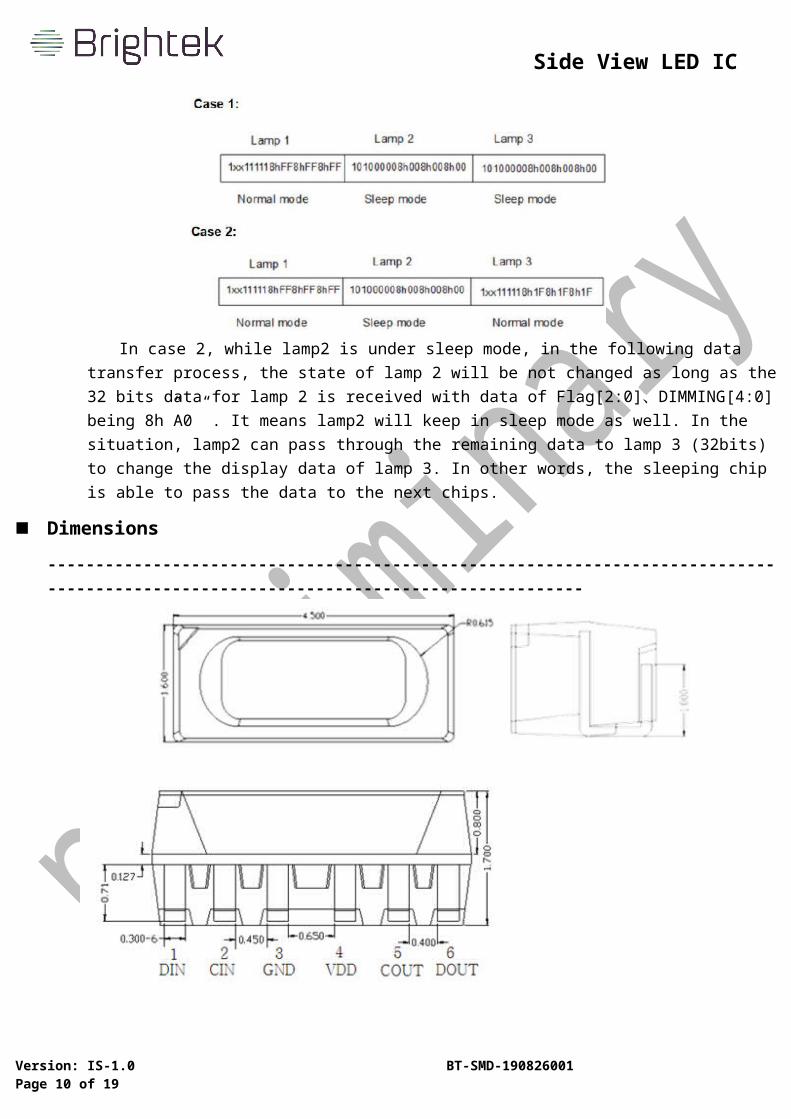
In case 2, while lamp2 is under sleep mode, in the following data transfer process, the state of lamp 2 will be not changed as long as the 32 bits data for lamp 2 is received with data of Flag[2:0]、DIMMING[4:0] being 8h”A0” . It means lamp2 will keep in sleep mode as well. In the situation, lamp2 can pass through the remaining data to lamp 3 (32bits) to change the display data of lamp 3. In other words, the sleeping chip is able to pass the data to the next chips.
Dimensions Version: IS-1.0 BT-SMD-190826001 Page 6 of 13

Side View LED IC
------------------------------------------------------------------------------------------------------------------------------------
§ All dimensions are in millimeters.§ Tolerance is ±0.1mm unless other specified§ Specifications are subject to change without notice
Version: IS-1.0 BT-SMD-190826001 Page 7 of 13

Side View LED IC
PIN Configuration ------------------------------------------------------------------------------------------------------------------------------------
No. Symbol Function description
1 DI Data input
2 CI Clock input
3 GND Ground
4 VDD Supply voltage
5 CO Clock output
6 DO Data output
Reflow Profile
Version: IS-1.0 BT-SMD-190826001 Page 8 of 13

Side View LED IC
------------------------------------------------------------------------------------------------------------------------------------1. IR reflow soldering Profile for Lead Free solder
25℃
2-5℃/sec
10sec. max
2-5℃/sec
120sec.Max50sec.max
0
50
100
150
200
250
300
0 50 100 150 200 250 300sec
℃ 1-5℃/sec
Pre heating 150-180℃
260℃ max
230℃ max
Time
tempe
rature
Notes: 1. We recommend the reflow temperature at 240℃ (±5℃), and the maximum soldering temperature should be limited to 260℃.
2. Don’t cause stress to the silicone resin while it is exposed to high temperature.3. Number of reflow process shall not be more than 1 time.
Test Circuit and Precautions for UseVersion: IS-1.0 BT-SMD-190826001 Page 9 of 13
Side View LED IC
------------------------------------------------------------------------------------------------------------------------------------1. Typical application circuit
Notes:
When the first LED is connected to the MCU, a resistance R is needed in series between its signal input
line and the MCU. The size of R depends on the number of cascade beads. The more cascades, the
smaller resistance R is used. It is generally recommended that the value be between 100-1K. Usually
the recommended value is around 300 R. In order to make the LEDs work more stably, a parallel
capacitor is needed between VDD and GND of each
2. Precautions for Use2.1. Over-current-proof
Customer must apply resistors for protection; otherwise slight voltage shift will cause big current change (Burn-out will happen).
2.2. Storage1). To store the products is recommended with following conditions:
Humidity: 60% R.H. Max.Temperature: 5℃~30℃(41℉~86℉)
2). Shelf life in sealed bag: 12 months at <5℃~30℃ and <60% R.H. after the package is Opened, the products should be used within 24 hours or they should be stored at ≦20%R.H. with zip-lock sealed bag.
2.3. BakingThe products are not used up within 24 hours, and please bake them before using:
1). 60±3℃ X 6hrs and <5% RH, for reel 2). 125±3℃ X 2hrs, for single LED
Packing------------------------------------------------------------------------------------------------------------------------------------
Dimensions of Reel (Unit: mm)
Version: IS-1.0 BT-SMD-190826001 Page 10 of 13

Side View LED IC
Dimensions of Tape (Unit: mm)
Arrangement of Tape
Packing
Version: IS-1.0 BT-SMD-190826001 Page 11 of 13
Notes:1. Empty component pockets sealed with top cover tape2. The max number of consecutive missing SMD is 2pcs;3. The cathode is put towards the tape sprocket hole in accordance with ANSI/EIA RS-481
specifications;4. 2000 pcs per reel;5. The remainders will be packed in a multiplication of 500pcs.

Side View LED IC
------------------------------------------------------------------------------------------------------------------------------------
Notes:Reeled product (max.2000 ) is packed in a sealed moisture-proof bag. Five bags are packed in an inner box
(size: about 260 X 230 X 100 mm) and four inner boxes are in an outer box (size: about 480 X 275 X 215 mm).
On the label of moisture-poof bag, there should be the information of Part No., Lot No. and quantity number;
also the total quantity number should be on inspection request form on outer box.
Version: IS-1.0 BT-SMD-190826001 Page 12 of 13
Packaging Specifications

Side View LED IC
Precautions-----------------------------------------------------------------------------------------------------------------------------------
1. Abnormal situation caused by improper setting of colletTo choose the right collet is the key issue in improving the product’s quality. LED is different from other
electronic components, which is not only about electrical output but also for optical output. This characteristic made LED more fragile in the process of SMT. If the collet’s lowering down height is not well set, it will bring damage to the gold wire at the time of collet’s picking up and loading which will cause the LED fail to light up, light up now and then or other quality problems2. How to choose the collet
During SMT, please choose the collet that has larger outer diameter than the lighting area of lens, in case that improper position of collet will damage the gold wire inside the LED. Different collets fit for different products, please refer to the following pictures cross out
3. Other points for attentionA. No pressure should be exerted to the epoxy shell of the SMD under high temperature.B. Do not scratch or wipe the lens since the lens and gold wire inside are rather fragile and cross out
easy to break.C. LED should be used as soon as possible when being taken out of the original package, and should
be stored in anti-moisture and anti-ESD package.
4. This usage and handling instruction is only for your reference.
Version: IS-1.0 BT-SMD-190826001 Page 13 of 13
Outer diameter of collet should be larger than the lighting area
Picture 1() Picture 2(X)