waterfront moama development - murrayriver.nsw.gov.au · prepared for sheep station pty ltd issue b...
TRANSCRIPT
PREPARED FOR
SHEEP STATION PTY LTD
ISSUE B - JUNE 2017
PRESSURE SYSTEM SOLUTIONS PTY LTD
www.pssolutions.net.au
WATERFRONT MOAMA DEVELOPMENT
DUAL WATER RETICULATION SYSTEM SUMMARY MASTERPLAN REPORT

Waterfront Moama Development Dual Water Reticulation System Summary Masterplan Report
Issue B – June 2017 ii
Document Information Prepared for Sheep Station Pty Ltd Project Name Waterfront Moama Development File Reference Dual System Summary Masterplan Report Job Reference 170330 Date 12 May 2017
Contact Information Pressure System Solutions Pty Ltd A B N 57 097 164 899 Unit 1/47-51 Lorraine Street Peakhurst NSW 2210 Sydney Australia T: +61 2 9584 1177 F: +61 2 9584 1477 E: [email protected] PO Box 630 Jannali NSW 2226
Document Control Version Date Issue Author Review / Approved
A 08.05.17 Draft EP SMW
B 05.06.17 Comments from client update EP
Document ID: J:\700-Projects\702-Current projects\170330 Deep Creek\720-Design\775-Reports\Deep Creek PW & RW Summary Masterplan Report Issue B.docx
© Intellectual Property
All rights reserved. No part of this document may be reproduced or transmitted in any form, or by any means, electronic, manual, photocopying or by any information storage and retrieval system without the written consent of Pressure System Solutions Pty Ltd.

Waterfront Moama Development Dual Water Reticulation System Summary Masterplan Report
Issue B – June 2017 iii
TABLE OF CONTENTS
EXECUTIVE SUMMARY ............................................................................................................................. 1
1.0 INTRODUCTION ........................................................................................................................... 4
1.1 BACKGROUND............................................................................................................................. 4 1.2 MASTERPLAN ............................................................................................................................. 5 1.3 REPORT OBJECTIVE .................................................................................................................... 5 1.4 BASE DATA ................................................................................................................................ 5
2.0 POTABLE WATER SYSTEM ........................................................................................................ 6
2.1 POTABLE WATER SYSTEM GENERAL DESCRIPTION ........................................................................ 6 2.2 STANDARDS ............................................................................................................................... 6 2.3 POTABLE WATER DESIGN PARAMETERS ....................................................................................... 6 2.4 POTABLE WATER DESIGN CRITERIA .............................................................................................. 8 2.5 FIRE HYDRANT LOCATIONS .......................................................................................................... 9 2.6 SUPER-LOT SERVICES ................................................................................................................ 9 2.7 RISK MANAGEMENT..................................................................................................................... 9 2.8 HYDRAULIC NETWORK MODELLING ............................................................................................. 10
3.0 RECYCLED WATER SYSTEM ................................................................................................... 13
3.1 RECYCLED WATER SYSTEM GENERAL DESCRIPTION .................................................................... 13 3.2 STANDARDS ............................................................................................................................. 13 3.3 RECYCLED WATER DESIGN PARAMETERS ................................................................................... 14 3.4 RECYCLED WATER DESIGN CRITERIA ......................................................................................... 15 3.5 FIRE HYDRANT LOCATIONS ........................................................................................................ 16 3.6 SUPER-LOT SERVICES ............................................................................................................... 16 3.7 RISK MANAGEMENT................................................................................................................... 17 3.8 HYDRAULIC NETWORK MODELLING ............................................................................................. 17
GLOSSARY .............................................................................................................................................. 21
APPENDIX A – DESIGN PLANS .............................................................................................................. 22
FIGURES
Figure 1: Potable Water Masterplan – MDD Maximum and Minimum Pressures ............................... 11
Figure 2: Potable Water Masterplan – MDD Headlosses ..................................................................... 12
Figure 3: Recycled Water Masterplan – MDD Maximum and Minimum Pressures ............................. 19
Figure 4: Recycled Water Masterplan – MDD Headlosses ................................................................... 20
Waterfront Moama Development Dual Water Reticulation System Summary Masterplan Report
Issue B – June 2017 iv
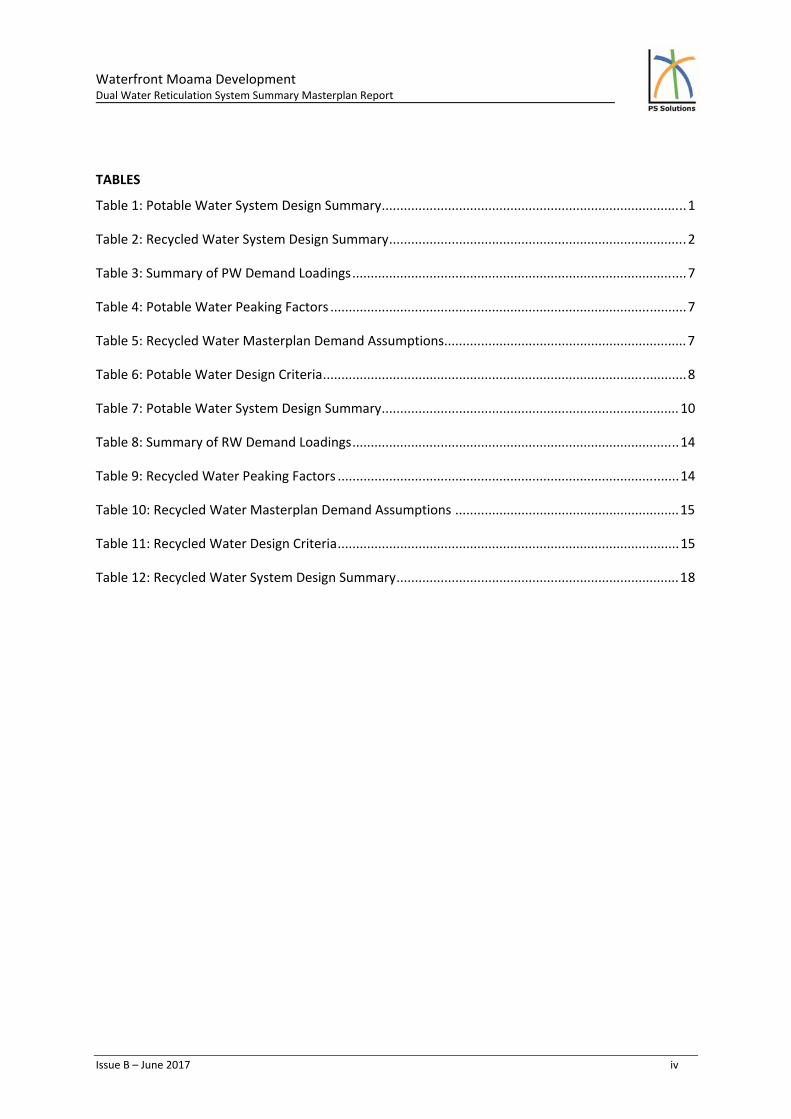
TABLES
Table 1: Potable Water System Design Summary ................................................................................... 1
Table 2: Recycled Water System Design Summary ................................................................................. 2
Table 3: Summary of PW Demand Loadings ........................................................................................... 7
Table 4: Potable Water Peaking Factors ................................................................................................. 7
Table 5: Recycled Water Masterplan Demand Assumptions.................................................................. 7
Table 6: Potable Water Design Criteria ................................................................................................... 8
Table 7: Potable Water System Design Summary ................................................................................. 10
Table 8: Summary of RW Demand Loadings ......................................................................................... 14
Table 9: Recycled Water Peaking Factors ............................................................................................. 14
Table 10: Recycled Water Masterplan Demand Assumptions ............................................................. 15
Table 11: Recycled Water Design Criteria ............................................................................................. 15
Table 12: Recycled Water System Design Summary ............................................................................. 18

Waterfront Moama Development Dual Water Reticulation System Summary Masterplan Report
Issue B – June 2017 1
EXECUTIVE SUMMARY
The Waterfront Moama Development is a residential and recreational development located approximately 18km north‐west of Moama, situated on the Murray River, and within the Murray Shire Council area. The recreation activities predominantly include Camping, Wakeboarding and Water‐skiing.
Once fully developed the area is expected to incorporate approximately 278 residential lots, 257 cabins, 100 campsites and 1 hotel. The land is being developed by Sheep Station Pty Ltd, and is proposed to be serviced under a private water utility model, providing drinking water, recycled water and sewerage services.
This Masterplan Report is for the potable water and recycled water reticulation network servicing the Waterfront Moama development and has been prepared for Sheep Station Pty Ltd.
Both the recycled water and the potable water systems have been designed for 100% washing machine usage. The parks are to be irrigated during non‐peak usage times; therefore it will not contribute to the design peak flow. However, the required volume for this usage needs to be accommodated within the water balance evaluation (determined by others).
The design parameters and standards are primarily based in accordance with Water Supply Code of Australia, WSA‐03‐2011‐3.1 Sydney Water 2014 Edition and the Murray Shire Council “ Engineering Guidelines for Subdivision and Development Standards: Part 4 – Water Reticulation 2012”.
This masterplan presents the concept design for the reticulation systems and sets the initial design parameters and assumptions for the ongoing design development of the Waterfront Moama development potable water and recycled water systems.
Summary of the Potable Water System Design
Design Criteria Accommodation Amenity Total Units
Dwellings 536 2 538 Lots
ADD (includes 100% washing machines)
263 17.6 280.6 KL/d
Average Day Demand 3.04 0.2 3.24 L/s
Max Day Demand 4.9 0.4 5.3 L/s
Max Hour Demand 13.2 1.3 14.5 L/s
Storage Reservoir (Total)
1.3 ML
‐ Stage W1 + W2 Reservoir Only
0.24 ML
‐ Fire Flow Storage (Additional to above)
0.14 ML
Pumping Station @ 35m/h
24 L/s
Table 1: Potable Water System Design Summary

Waterfront Moama Development Dual Water Reticulation System Summary Masterplan Report
Issue B – June 2017 2
Potable Water Key Infrastructure
A storage reservoir located at the STP indicatively sized at 1.3ML for the ultimate masterplan.
An interim storage reservoir to service Stage W1 and W2 indicatively sized at 0.23ML.
A pump station indicatively sized with a duty of 24l/s at 35m/head.
The reticulation network required is a combination of DN150 and DN100 pipes.
Summary of the Recycled Water System Design
Design Criteria Accommodation Amenity Total Units
Dwellings 536 2 538 Lots
ADD (includes 100% washing machines)
184 2.4 186.4 KL/d
Average Day Demand 2.13 0.03 2.16 L/s
Max Day Demand 9.73 0.06 9.8 L/s
Max Hour Demand 35 0.18 35.2 L/s
Storage Reservoir 0.9 ML
‐ Stage W1 + W2 Reservoir Only
0.16 ML
Pumping Station @ 30m/h
35 L/s
Table 2: Recycled Water System Design Summary
Key Infrastructure
A storage reservoir located at the STP indicatively sized at 0.9ML.
An interim storage reservoir to service Stage W1 and W2 indicatively sized at 0.16ML.
A pump station indicatively sized with a duty of 35l/s at 30m/head.
The reticulation network required is a combination of DN200, DN150 & DN100 pipes.
Risk Management
The infrastructure has been planned and sized in accordance with relevant design codes (as detailed in this report) rather than real data from similar sites. However prior to finalising the sizing of some key infrastructure elements, a risk assessment should be undertaken to determine how the system will operate including the interaction with the Potable and Recycled Water Supply. Some of the key identified risks include;
Providing adequate potable water security of supply for the Waterfront Moama development including back‐up to the RWTP, if required.
Determine the recycled water reservoir size, including irrigation if required, and source of back‐up supply, eg. from the potable water supply system or raw water from the Murray River;
Waterfront Moama Development Dual Water Reticulation System Summary Masterplan Report
Issue B – June 2017 3
Detailed design to determine size of reservoirs and pump stations.
Due to the relatively low number of connections per pipe length and network redundancy, the velocities within the system are low, therefore planned maintenance structures and activities will need to include flushing program.
The Distribution Water Pump Station (located at the RWTP site) is sized for MHD, including fire‐fighting flows of 10l/s;
Waterfront Moama Development Dual Water Reticulation System Summary Masterplan Report
Issue B – June 2017 4
1.0 INTRODUCTION
1.1 Background
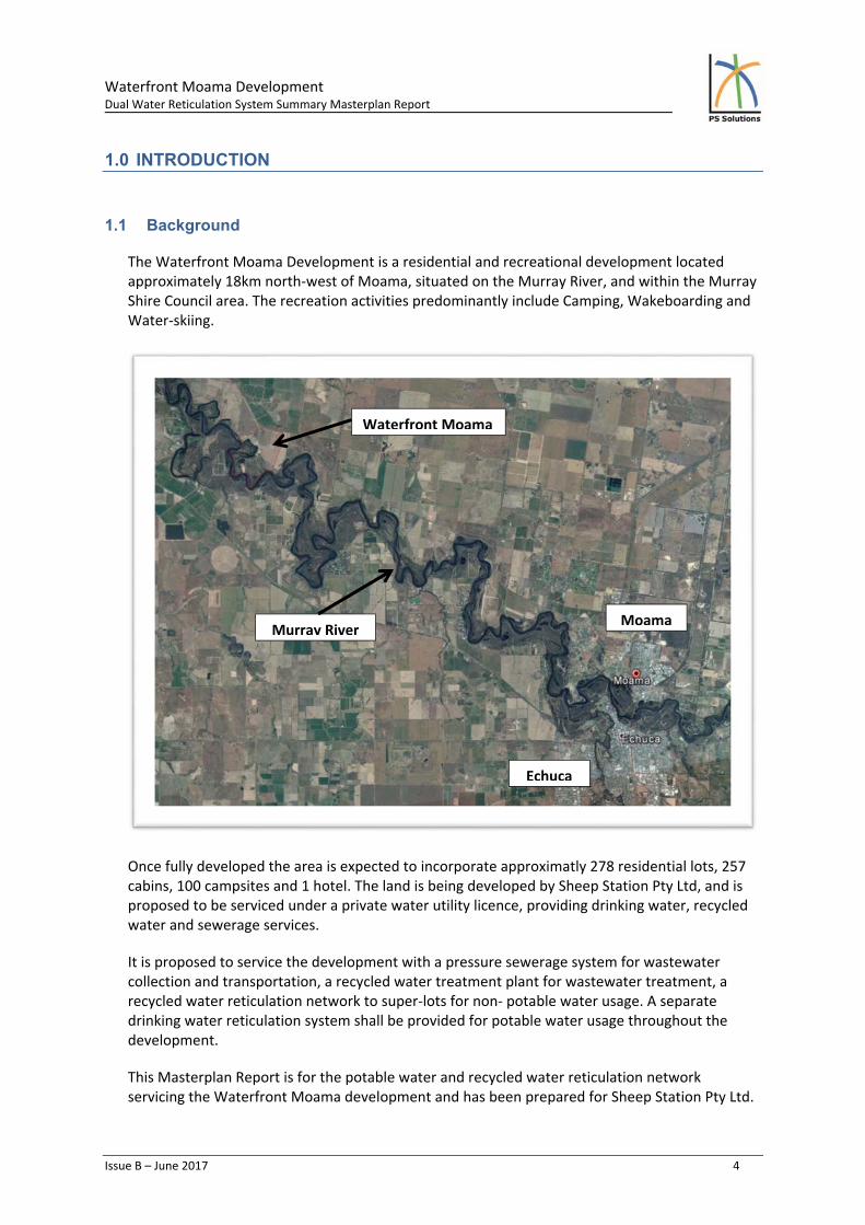
The Waterfront Moama Development is a residential and recreational development located approximately 18km north‐west of Moama, situated on the Murray River, and within the Murray Shire Council area. The recreation activities predominantly include Camping, Wakeboarding and Water‐skiing.
Once fully developed the area is expected to incorporate approximatly 278 residential lots, 257 cabins, 100 campsites and 1 hotel. The land is being developed by Sheep Station Pty Ltd, and is proposed to be serviced under a private water utility licence, providing drinking water, recycled water and sewerage services.
It is proposed to service the development with a pressure sewerage system for wastewater collection and transportation, a recycled water treatment plant for wastewater treatment, a recycled water reticulation network to super‐lots for non‐ potable water usage. A separate drinking water reticulation system shall be provided for potable water usage throughout the development.
This Masterplan Report is for the potable water and recycled water reticulation network servicing the Waterfront Moama development and has been prepared for Sheep Station Pty Ltd.
Waterfront Moama
Moama
Echuca
Murray River
Waterfront Moama Development Dual Water Reticulation System Summary Masterplan Report
Issue B – June 2017 5
1.2 Masterplan
The masterplan scope of works includes:
1) Design Criteria ‐ Assess ultimate loadings and set the initial design parameters and assumptions for the potable water and recycled water services;
2) Design and Performance of the potable water and recycled water systems.
Associated works not included within the scope of this Masterplan are:
Potable and Recycled Water Supply Strategy to the reservoirs;
Water Balance;
Recycled Water Treatment Plant;
Detail design of any of the above services, including the potable and recycled water systems.
1.3 Report Objective
The objective of this report is to present potable water system and recycled water system masterplan designs for the Waterfront Moama Development, for submission to the relevant authorities.
This masterplan report presents the concept design for the reticulation systems and sets the initial design parameters and assumptions for the ongoing design development of the Waterfront Moama development potable water and recycled water systems.
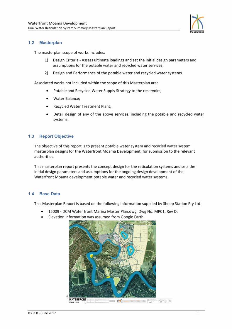
1.4 Base Data
This Masterplan Report is based on the following information supplied by Sheep Station Pty Ltd.
15009 ‐ DCM Water front Marina Master Plan.dwg, Dwg No. MP01, Rev D;
Elevation information was assumed from Google Earth.

Waterfront Moama Development Dual Water Reticulation System Summary Masterplan Report
Issue B – June 2017 6
2.0 POTABLE WATER SYSTEM
2.1 Potable Water System General Description
In a dual reticulation area, potable water is to supply those components of water usage that are directly or indirectly consumed by humans. The key components of the potable water supply network include:
Storage Reservoir – Serve to buffer Max Hour Demand (MHD) as well provide emergency storage should there be a failure in the water supply. The masterplan design has indicatively sized the reservoir at 1.3ML, with the capacity to supply 24 hours max day demand into the potable water system plus back‐up supply of 24hrs max day demand into the recycled water system.
Pump Station – Provides a boost to the pressure coming out of the reservoir so that all properties receive a minimum pressure of 20m and maintain a pressure differential of 5m with the recycled water system. The Pump Station is designed to meet MHD and fire‐fighting flows of 10l/s, whilst maintaining minimum 20m at the hydrant. The Pump Station will be in a VSD configuration, have a one pump redundancy and may have a back‐up electricity supply (eg. generator) to cover failure scenarios. For the masterplanning study, the pump station was modelled with a duty of 24l/s at 35m/head.
Reticulation Mains – The reticulation network required is a combination of DN150 and DN100 pipes. The pipework proposed is to be PVC‐M (Series 2) in accordance with Table 4.1 from Water Supply Code of Australia, WSA 03‐2011‐3.1. Isolation vales and hydrants will be spread throughout the reticulation system, located in accordance with Murray Shire Council Engineering Guidelines for Subdivisions and Development Standards, Part 4 2012 and WSA 03‐2011‐3.1, to assist with fire‐fighting, maintenance and repairs.
2.2 Standards
The work shall comply with the Water Supply Code of Australia, WSA‐03‐2011‐3.1 Sydney Water 2014 Edition.
The mains shall extend to all sections in the development generally in a ring main system of 150mm and 100 mm pipes. Dead ends within the network will be avoided, where possible, in accordance with Water Supply Code of Australia, WSA‐03‐2011‐3.1 Sydney Water 2014 Edition.
2.3 Potable Water Design Parameters
The system design parameters were based on the Water Supply Code of Australia WSA 03‐2011 Sydney Water 2014 Edition for Single Residential Dwellings for dual water supply system and are summarized in below.
Waterfront Moama Development Dual Water Reticulation System Summary Masterplan Report
Issue B – June 2017 7
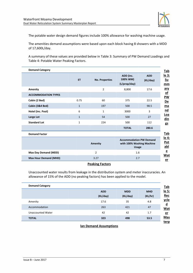
The potable water design demand figures include 100% allowance for washing machine usage.
The amenities demand assumptions were based upon each block having 8 showers with a MDD of 17,600L/day.
A summary of these values are provided below in Table 3: Summary of PW Demand Loadings and Table 4: Potable Water Peaking Factors.
Table 3: Summary of PW Demand Loadings
Table 4: Potable
Water
Peaking Factors
Unaccounted water results from leakage in the distribution system and meter inaccuracies. An allowance of 15% of the ADD (no peaking factors) has been applied to the model.
Table 5: Recycled
Water Masterp
lan Demand Assumptions
Demand Category
ET No. Properties
ADD (inc. 100% WM)
(L/prop/day)
ADD
(KL/day)
Amenity 2 8,800 17.6
ACCOMMODATION TYPES
Cabin (2 Bed) 0.75 60 375 22.5
Cabin (3&4 Bed) 1 197 500 98.5
Hotel (inc. Pool) 6 1 3000 3
Large Lot 1 54 500 27
Standard Lot 1 224 500 112
TOTAL 280.6
Demand Factor
Amenity
Accommodation PW Demand with 100% Washing Machine
Usage
Max Day Demand (MDD) 2 1.6
Max Hour Demand (MHD) 3.27 2.7
Demand Category
ADD
(KL/day)
MDD
(KL/day)
MHD
(KL/hr)
Amenity 17.6 35 4.8
Accommodation 263 421 47
Unaccounted Water 42 42 1.7
TOTAL 323 498 53.5

Waterfront Moama Development Dual Water Reticulation System Summary Masterplan Report
Issue B – June 2017 8
2.4 Potable Water Design Criteria
Design Criteria detailed below in Table 3.3 are from WSA 03‐2011‐3.1 SWC 2014 Edition and Murray Shire Council Engineering Guidelines for Subdivisions and Development Standards.
Design Criteria
Maximum Pressure 80m Head
Minimum Pressure 20m Head
Pressure Differential The potable water system is to have higher operational pressure than the recycled water system. Minimum pressure differential 5m
head.
Max head Loss 5 m/km For pipes 150mm and Less
3m/km for pipes 200mm dia and greater
Reservoir Storage Minimum of 24 hrs of PW MDD + 24hrs RW MDD backup supply
K Factor (Clause 3.2.5.3) 0.3 for distribution mains
Leakage Loss 15% ADD, peaking factors not applied
Velocities Maximum 6.0 m/s
Minimum 0.5m/s*
*Minimum pipe size 100mm
Table 6: Potable Water Design Criteria
The potable water supply mechanism is currently unknown, therefore to manage this supply risk the reservoir was sized conservatively.
We understand that fire flow capacity is to based on 10l/s for 4 hours, this equates to a storage capacity of 0.144ML. However it should be noted that this additional capacity has NOT been included in the indicative reservoir storage size. This fire flow allowance should be accommodated in a separate tank or added to the system PW storage reservoir.
Note the potable water design criteria from WSA 03‐2011‐3.1 SWC Edition, nominates a pressure differential of 5m head between the potable water supply and the recycled water supply. The design intent is to provide the pressure differential on commissioning based on the normal operating pressures in the potable water mains serving the locality, on the condition that the reduced pressure provides suitable performance in the recycled water mains.
Additional measures are to be adopted in the Waterfront Moama development to minimise the risk of cross connection between the recycled and the potable water main supply. These measures include:
The pipe colour, valve box covers, and markings to be in accordance the WSA 03‐2011‐3.1 SWC Edition.
The flow in the recycled water main to be intelligently monitored, with any irregularities in the flow or unexpected increase in flows will trigger an alarm.
Pressure Testing and flow testing to include isolation of the service not being tested, which will be monitored to ensure no flows are present
Each tap in the domestic installations to be fully flow tested to confirm correct connection.

Waterfront Moama Development Dual Water Reticulation System Summary Masterplan Report
Issue B – June 2017 9
2.5 Fire Hydrant Locations
The potable water supply for the Waterfront Moama development will be the nominated fire supply service with hydrants located in accordance with the Murray Shire Council “Engineering Guidelines for Subdivisions and Development Standards: Part 4 – Water Reticulation 2012”.
In accordance with the Murray Shire Council “ Engineering Guidelines for Subdivision and Development Standards: Part 4 – Water Reticulation 2012” the potable water supply network design has been tested to be able to provide 10l/s fire‐fighting capacity with a minimum supply head at the hydrant of 20m during MHD.
Hydrants in the potable water network shall be located in accordance with WSA 03‐2011‐3.1 Clause 8.8, generally located:
At system high points and lows points,
At end of lines,
In other locations required to maintain the reticulation network.
Hydrant installation detail and location markings and signage to be in accordance with WSA 03‐2011‐3.1 SWC Edition.
2.6 Super-Lot Services
Potable water shall be supplied to each lot via a water meter assembly in accordance with WSA 03‐2011‐3.1 SWC Edition, adjacent to the recycled water meter.
2.7 Risk Management
The infrastructure has been planned and sized in accordance with relevant design codes (as detailed in this report) however prior to finalising the sizing of some key infrastructure elements, a risk assessment should be undertaken to determine how the system will operate including the interaction with the Recycled Water Supply. Some of the key identified risks include;
Providing adequate security of supply for the Waterfront Moama development including back‐up to the RWTP, if required;
Design parameters and assumptions are based relevant available design codes rather than real data from similar serviced areas;
Detailed design to determine size of reservoir and pump station.
Due to the relatively low number of connections per pipe length and network redundancy, the velocities within the system are low, therefore planned maintenance structures and activities will need to include flushing program.
The Distribution Pump Station (located at the RWTP site) is sized for PHD, including fire‐fighting flows of 10l/s;

Waterfront Moama Development Dual Water Reticulation System Summary Masterplan Report
Issue B – June 2017 10
Review of the proposed potable water usage across the development and associated impact on the demand categories and assumptions, such as the cabins (3&4 bed) are assigned the same demand as the standard lots and large lots.
2.8 Hydraulic Network Modelling
The potable water supply network was modelled using Infoworks WS. Hydraulic analysis was
undertaken with the following parameters:
The demand adopted in the model was in accordance with Table 3, Table 4 & Table 5;
The network pipes were sized to meet the design requirements provided in Table 6;
Reservoir and pumping station was sized to meet the design criteria detailed in Table 6 and summarised in Table 7: Potable Water System Design Summary.
Design Criteria Accommodation Amenity Total Units
Dwellings 536 2 538 Lots
ADD (includes 100% washing machines)
263 17.6 280.6 KL/d
Average Day Demand 3.04 0.2 3.24 L/s
Max Day Demand 4.9 0.4 5.3 L/s
Max Hour Demand 13.2 1.3 14.5 L/s
Storage Reservoir (Total)
1.3 ML
‐ Stage W1 + W2 Reservoir Only
0.24 ML
‐ Fire Flow Storage (Additional to above)
0.14 ML
Pumping Station @ 35m/h
24 L/s
Table 7: Potable Water System Design Summary
Hydraulic network modelling results are provided in Figure 1, and show the minimum potable water pressure in the system to be 30m with the maximum up to 40m.
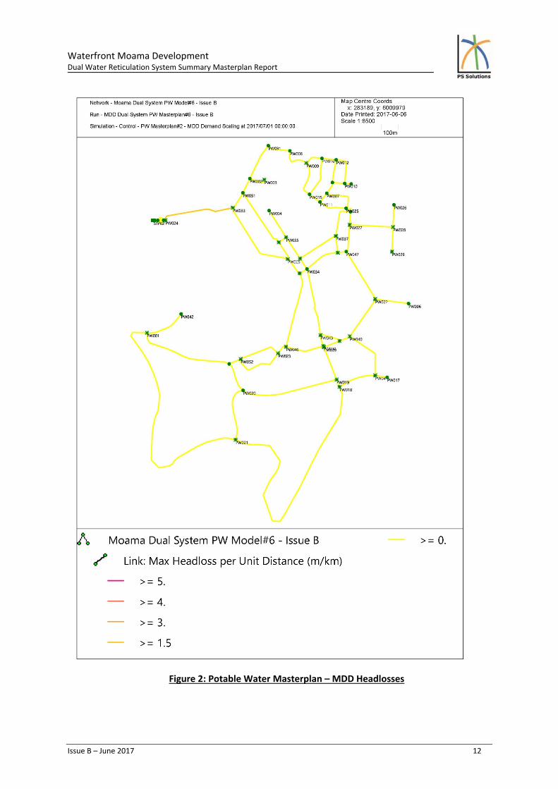
The maximum headloss per unit distance (m/km) shown in Figure 2 indicate that the system is performing within the design criteria set‐out in Table 6: Potable Water Design Criteria.

Waterfront Moama Development Dual Water Reticulation System Summary Masterplan Report
Issue B – June 2017 11
Figure 1: Potable Water Masterplan – MDD Maximum and Minimum Pressures
Waterfront Moama Development Dual Water Reticulation System Summary Masterplan Report
Issue B – June 2017 12
Figure 2: Potable Water Masterplan – MDD Headlosses

Waterfront Moama Development Dual Water Reticulation System Summary Masterplan Report
Issue B – June 2017 13
3.0 RECYCLED WATER SYSTEM
3.1 Recycled Water System General Description
Recycled water system supplies the non‐potable component of domestic water usage typically for outdoor water irrigation and washdown, toilet flushing and washing machine usage.
The key components of the recycled water supply network include:
Storage Reservoir – Serve to buffer Max Hour Demand as well provide emergency storage should there be a failure in the RWT Plant. The storage reservoir is proposed to be located on the same site as STP which is at a ground level of approx. 96m AHD. For the masterplanning study, the reservoir was indicatively sized at 0.9ML based on 24hr MDD.
Pumping Station – Provides a boost to the pressure coming out of the reservoir so that all properties receive a minimum pressure of 20m, whilst maintaining a pressure differential of 5m with the potable water system. The VSD pumping station will have a one pump redundancy as well as a back‐up electricity supply (e.g. Generator) to cover numerous failure scenarios. For the masterplanning study, the pump station was modelled with a duty of 35l/s at 30m/head.
Reticulation Mains – The reticulation network required is a combination of DN200, DN150 and DN100 pipes. The pipework proposed is to be lilac colour PVC pipe and in accordance with Table 4.1 from the Water Supply Code of Australia, WSA‐03‐2011‐3.1. Isolation vales and hydrants will be spread throughout the reticulation system to assist with maintenance and repairs.
3.2 Standards
The work shall comply with the Water Supply Code of Australia, Sydney Water Edition WSA‐03‐2011‐3.1. It should be noted that the Waterfront Moama Development recycled water system is not designed as an essential fire‐fighting source, and is therefore not designed with fire hydrants for fire‐fighting purposes. Hydrants for fire‐fighting are to be located in the potable water supply system. Hydrants in the recycled water system are intended for operation and maintenance purposes only.
The recycled water reticulation system shall commence at the connection to the recycled water delivery system at the RWTP. Refer to the Recycled Water Treatment Plant design for details of the VSD delivery pump pressure system.
The mains shall extend to all sections in the development generally in a ring main system of DN200, DN150 and DN100 pipes. Dead ends within the network will be avoided, where possible, accordance with Water Supply Code of Australia, Sydney Water Edition WSA‐03‐2011‐3.1.
Recycled water shall be as a non‐potable water supply, supplying recycled water for toilet flushing, clothes washing, irrigation and external washdown. There have been no parks or reserves nominated for irrigation supply with the development, however it is assumed that any

Waterfront Moama Development Dual Water Reticulation System Summary Masterplan Report
Issue B – June 2017 14
irrigation that occurs will be conducted outside of peak times; therefore it will not contribute to the design peak flow. However, the required volume for this usage needs to be accommodated within the water balance evaluation.
All pipework in the recycled water supply network is less than DN300mm, therefore no air valves are required in accordance with WSA 03‐2011‐3.1 Water Supply Code of Australia SWC Edition Clause 8.4.
3.3 Recycled Water Design Parameters
The system design parameters were based on the Water Supply Code of Australia WSA 03‐2011 Sydney Water Edition for Single Residential Dwellings with 100% washing machine (WM) usage from the potable water network. Both the potable and recycled water systems have been designed to accommodate 100% washing machine usage.
The amenities demand assumptions were based upon recycled water supplying toilet flushing for 100 campsites, with 4 people per campsite, equating to a MDD of 2,400L/day.
A summary of these values are provided below in Table 8: Summary of RW Demand Loadings and Table 9: Recycled Water Peaking Factors.
Table 8: Summary of RW Demand Loadings
Table 9: Recycled
Water
Peaking Factors
In accordance with WSA 03‐2011‐3.1 SWC Edition Clause 3.1.5 the recycled water system does
not include an allowance for fire‐fighting flows.
Demand Category
ET No. Properties
ADD
(L/prop/day)
ADD
(KL/day)
Amenity 2 1200 2.4
ACCOMMODATION TYPES
Cabin (2 Bed) 0.75 60 262.5 15.75
Cabin (3&4 Bed) 1 197 350 68.95
Hotel (inc. Pool) 6 1 2,100 2.1
Large Lot 1 54 350 18.9
Standard Lot 1 224 350 78.4
TOTAL 186.5
Demand Factor
Amenity
Accommodation RW Demand with 100% Washing Machine
Usage
Max Day Demand (MDD) 2 4.57
Max Hour Demand (MHD) 3.27 3.6
Waterfront Moama Development Dual Water Reticulation System Summary Masterplan Report
Issue B – June 2017 15
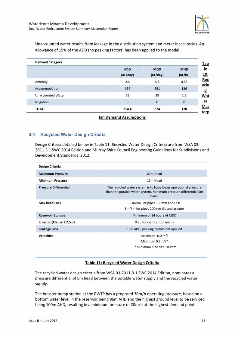
Unaccounted water results from leakage in the distribution system and meter inaccuracies. An
allowance of 15% of the ADD (no peaking factors) has been applied to the model.
Table 10: Recycled
Water Masterp
lan Demand Assumptions
3.4 Recycled Water Design Criteria
Design Criteria detailed below in Table 11: Recycled Water Design Criteria are from WSA 03‐2011‐3.1 SWC 2014 Edition and Murray Shire Council Engineering Guidelines for Subdivisions and Development Standards, 2012.
Design Criteria
Maximum Pressure 80m Head
Minimum Pressure 15m Head
Pressure Differential The recycled water system is to have lower operational pressure than the potable water system. Minimum pressure differential 5m
head.
Max head Loss 5 m/km For pipes 150mm and Less
3m/km for pipes 200mm dia and greater
Reservoir Storage Minimum of 24 hours of MDD
K Factor (Clause 3.2.5.3) 0.25 for distribution mains
Leakage Loss 15% ADD, peaking factors not applied
Velocities Maximum 6.0 m/s
Minimum 0.5m/s*
*Minimum pipe size 100mm
Table 11: Recycled Water Design Criteria
The recycled water design criteria from WSA 03‐2011‐3.1 SWC 2014 Edition, nominates a pressure differential of 5m head between the potable water supply and the recycled water supply.
The booster pump station at the RWTP has a proposed 30m/h operating pressure, based on a bottom water level in the reservoir being 96m AHD and the highest ground level to be serviced being 100m AHD, resulting in a minimum pressure of 20m/h at the highest demand point.
Demand Category
ADD
(KL/day)
MDD
(KL/day)
MHD
(KL/hr)
Amenity 2.4 4.8 0.65
Accommodation 184 841 126
Unaccounted Water 28 28 1.2
Irrigation 0 0 0
TOTAL 214.4 874 128

Waterfront Moama Development Dual Water Reticulation System Summary Masterplan Report
Issue B – June 2017 16
Additional measures are to be adopted in the Waterfront Moama development to minimise the risk of cross connection between the recycled and the potable water main supply. These measures include:
The pipe colour, valve box covers, and markings to be in accordance the WSA 03‐2011‐3.1;
The flow in the recycled water main to be intelligently monitored, with any irregularities in the flow or unexpected increase in flows to trigger an alarm;
Pressure Testing and flow testing to include isolation of the service not being tested, which will be monitored to ensure no flows are present; and
Each tap in the domestic installations to be flow tested to confirm connection to the correct system.
3.5 Fire Hydrant Locations
The recycled water supply to the Waterfront Moama development is not designed as an essential fire‐fighting service. The potable water supply is to be the fire supply service with hydrants located in accordance with Murray Shire Council Engineering Guidelines for Subdivisions and Developments.
Hydrants in the recycled water system shall be provided for operational purposes only. Hydrants in the recycled water network shall be located in accordance with WSA 03‐2011‐3.1 Clause 8.8, generally located:
At system high points and lows points
At isolation valves, branch lines and end of lines
In other locations required to maintain the reticulation network
Hydrant installation detail and location markings and signage to be in accordance with WSA 03‐2011‐3.1 SWC Edition.
3.6 Super-lot Services
Recycled Water shall be supplied to each super‐lot via a water meter assembly in accordance
with WSA 03‐2011‐3.1 SWC Edition, adjacent to the potable water meter.
Recycled water shall be reticulated within the super‐lot in accordance with guidelines and
regulations.

Waterfront Moama Development Dual Water Reticulation System Summary Masterplan Report
Issue B – June 2017 17
3.7 Risk Management
The infrastructure has been planned and sized in accordance with relevant design codes (as detailed in this report) however prior to finalising the sizing of some key infrastructure elements, a risk assessment should be undertaken to determine how the system will operate including the interaction with the Potable Water Supply. Some of the key identified risks include;
Determine the reservoir size, including irrigation if required, and source of back‐up supply, eg. from the potable water supply system or raw water from the Murray River;
Design parameters and assumptions are based relevant available design codes rather than real data from similar serviced areas;
Review of the proposed recycled water usage across the development and associated impact on the demand categories and assumptions, such as there is currently no allowance for irrigation, the cabins (3&4 bed) are assigned the same demand as the standard lots and large lots.
Determine recycled water usage at the hotel, nominal figure of 2.1KL/day assigned in masterplan.
Detailed design to determine size of reservoir and pump station.
Due to the relatively low number of connections per pipe length, the velocities within the system are low, therefore planned maintenance structures and activities will need to include flushing program.
3.8 Hydraulic Network Modelling
The recycled water supply network was modelled using Infoworks WS. Hydraulic analysis was undertaken with the following parameters:
The demand adopted in the model was in accordance with Table 8,Table 9 & Table 10;
The network pipes were sized to meet the design requirements provided in Table 11;
Reservoir and pumping station were sized to meet the design criteria detailed in Table 11.
The recycled water system masterplan design is summarised in the table below.
Design Criteria Accommodation Amenity Total Units
Dwellings 536 2 538 Lots
ADD (includes 100% washing machines)
184 2.4 186.4 KL/d
Average Day Demand 2.13 0.03 2.16 L/s
Max Day Demand 9.73 0.06 9.8 L/s
Max Hour Demand 35 0.18 35.2 L/s
Waterfront Moama Development Dual Water Reticulation System Summary Masterplan Report
Issue B – June 2017 18
Design Criteria Accommodation Amenity Total Units
Storage Reservoir 0.9 ML
‐ Stage W1 + W2 Reservoir Only
0.16 ML
Pumping Station @ 30m/h
35 L/s
Table 12: Recycled Water System Design Summary
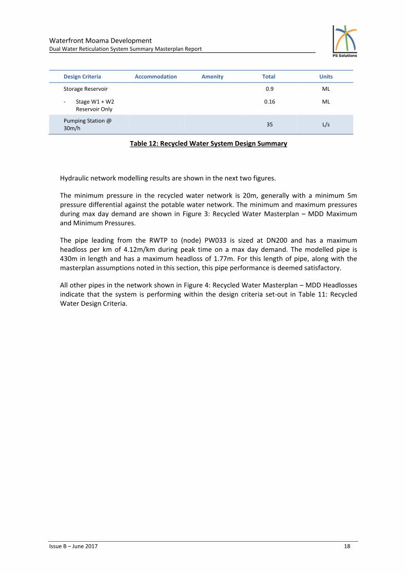
Hydraulic network modelling results are shown in the next two figures.
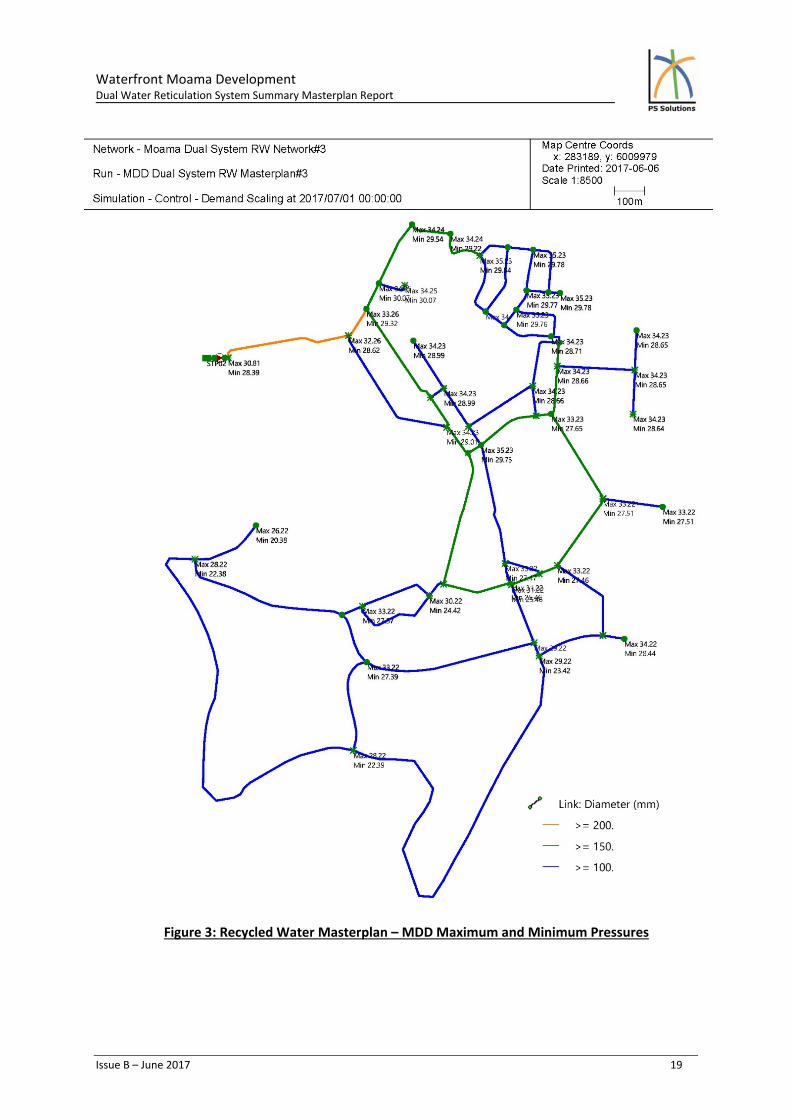
The minimum pressure in the recycled water network is 20m, generally with a minimum 5m pressure differential against the potable water network. The minimum and maximum pressures during max day demand are shown in Figure 3: Recycled Water Masterplan – MDD Maximum and Minimum Pressures.
The pipe leading from the RWTP to (node) PW033 is sized at DN200 and has a maximum headloss per km of 4.12m/km during peak time on a max day demand. The modelled pipe is 430m in length and has a maximum headloss of 1.77m. For this length of pipe, along with the masterplan assumptions noted in this section, this pipe performance is deemed satisfactory.
All other pipes in the network shown in Figure 4: Recycled Water Masterplan – MDD Headlosses indicate that the system is performing within the design criteria set‐out in Table 11: Recycled Water Design Criteria.
Waterfront Moama Development Dual Water Reticulation System Summary Masterplan Report
Issue B – June 2017 19
Figure 3: Recycled Water Masterplan – MDD Maximum and Minimum Pressures

Waterfront Moama Development Dual Water Reticulation System Summary Masterplan Report
Issue B – June 2017 20
Figure 4: Recycled Water Masterplan – MDD Headlosses
Waterfront Moama Development Dual Water Reticulation System Summary Masterplan Report
Issue B – June 2017 21
GLOSSARY
ADD Average Day Demand
AHD Australian Height Datum
BWL Bottom Water Level
Dw Dwelling
ET Equivalent Tenement
Ha Hectare
HDPE High Density Polyethylene
KPI Key Performance Indicators
MDD Maximum Day Demand
MHD Maximum Hour Demand
m/h Metres head
ML Megalitre
OD Outside Diameter
RL Reduced Level
PDD Peak Day Demand
PHD Peak Hour Demand
PE Polyethylene
PVC Polyvinylchloride
RWTP Recycled Water Treatment Plant
TDH Total Dynamic Head
TWL Top Water Level
WM Washing Machine
WPS Water pumping station
VSD Variable Speed Drive
Waterfront Moama Development Dual Water Reticulation System Summary Masterplan Report
Issue B – June 2017 22
APPENDIX A – DESIGN PLANS