wago-i/o-system 750 with sma data manager m
TRANSCRIPT

EDMM-WAGO-IO-IA-en-11 | Version 1.1ENGLISH
Installation ManualWAGO-I/O-SYSTEM 750 withSMA DATA MANAGER M

Legal Provisions SMA Solar Technology AG
Installation ManualEDMM-WAGO-IO-IA-en-112
Legal ProvisionsThe information contained in these documents is the property of SMA Solar Technology AG. No part of this documentmay be reproduced, stored in a retrieval system, or transmitted, in any form or by any means, be it electronic,mechanical, photographic, magnetic or otherwise, without the prior written permission of SMA Solar Technology AG.Internal reproduction used solely for the purpose of product evaluation or other proper use is allowed and does notrequire prior approval.SMA Solar Technology AG makes no representations or warranties, express or implied, with respect to thisdocumentation or any of the equipment and/or software it may describe, including (with no limitation) any impliedwarranties of utility, merchantability, or fitness for any particular purpose. All such representations or warranties areexpressly disclaimed. Neither SMA Solar Technology AG nor its distributors or dealers shall be liable for any indirect,incidental, or consequential damages under any circumstances.The exclusion of implied warranties may not apply in all cases under some statutes, and thus the above exclusion maynot apply.Specifications are subject to change without notice. Every attempt has been made to make this document complete,accurate and up-to-date. Readers are cautioned, however, that product improvements and field usage experience maycause SMA Solar Technology AG to make changes to these specifications without advance notice, or per contractprovisions in those cases where a supply agreement requires advance notice. SMA Solar Technology AG shall not beresponsible for any damages, including indirect, incidental or consequential damages, caused by reliance on thematerial presented, including, but not limited to, omissions, typographical errors, arithmetical errors or listing errors inthe content material.
TrademarksAll trademarks are recognized, even if not explicitly identified as such. Missing designations do not mean that aproduct or brand is not a registered trademark.
SMA Solar Technology AGSonnenallee 134266 NiestetalGermanyTel. +49 561 9522-0Fax +49 561 9522-100www.SMA.deEmail: [email protected] of: 2/28/2020Copyright © 2020 SMA Solar Technology AG. All rights reserved.

Table of ContentsSMA Solar Technology AG
Installation Manual 3EDMM-WAGO-IO-IA-en-11
Table of Contents1 Information on this Document..................................................................................................... 5
1.1 Validity ............................................................................................................................................................. 51.2 Target Group ................................................................................................................................................... 51.3 Content and Structure of this Document......................................................................................................... 51.4 Levels of Warning Messages.......................................................................................................................... 51.5 Symbols in the Document................................................................................................................................ 51.6 Typographies in the Document ....................................................................................................................... 6
2 Safety ............................................................................................................................................ 72.1 Intended Use.................................................................................................................................................... 72.2 IMPORTANT SAFETY INSTRUCTIONS......................................................................................................... 7
3 Scope of Delivery ......................................................................................................................... 10
4 Product Overview ........................................................................................................................ 114.1 WAGO-I/O-SYSTEM 750 ............................................................................................................................. 114.2 Fieldbus coupler............................................................................................................................................... 114.3 DC 24 V supply module ................................................................................................................................. 134.4 I/O modules .................................................................................................................................................... 144.5 Bus end terminal 750-600.............................................................................................................................. 154.6 Hardware address (MAC ID)......................................................................................................................... 154.7 Design guidelines and standards ................................................................................................................... 154.8 LED Signals ...................................................................................................................................................... 16
5 Mounting....................................................................................................................................... 225.1 Requirements for Mounting............................................................................................................................. 225.2 Mounting the product on the mounting rail ................................................................................................... 23
6 Connection .................................................................................................................................... 256.1 Overview of the Connection Area.................................................................................................................. 256.2 Connecting the conductor the CAGE CLAMP®............................................................................................ 256.3 Information on shielding.................................................................................................................................. 266.4 Functional grounding....................................................................................................................................... 266.5 Voltage supply terminal .................................................................................................................................. 27
6.5.1 Overcurrent protection..................................................................................................................................... 276.5.2 Potential isolation ............................................................................................................................................. 276.5.3 System supply................................................................................................................................................... 276.5.4 Power supply design........................................................................................................................................ 286.5.5 Connecting different components at the I/O modules .................................................................................. 29
6.5.5.1 8-channel DC 24 V digital input terminal...................................................................................................... 296.5.5.2 8-channel DC 24 V digital output terminal ................................................................................................... 306.5.5.3 2/4-channel analog input terminal (TempIN)............................................................................................... 326.5.5.4 4-channel analog input terminal 4 mA to 20 mA......................................................................................... 336.5.5.5 4-channel analog output terminal 0 mA to 20 mA....................................................................................... 34
6.5.6 Connection to Data Manager M.................................................................................................................... 36
7 Commissioning ............................................................................................................................. 387.1 Connecting the WAGO-I/O-SYSTEM 750 with Data Manager M ............................................................ 387.2 Assigning the IP address ................................................................................................................................. 387.3 Configuring the WAGO-I/O-SYSTEM 750 via Data Manager M user interface...................................... 39
7.3.1 Device registration ........................................................................................................................................... 39

Table of Contents SMA Solar Technology AG
Installation ManualEDMM-WAGO-IO-IA-en-114
7.3.2 Selecting the device for configuring sensors .................................................................................................. 407.3.3 Defining the input and function for configuring sensors ................................................................................ 407.3.4 Defining the channel and scaling for grid management services ................................................................. 447.3.5 Displaying measured values locally on the Data Manager M Modbus server........................................... 49
8 Troubleshooting............................................................................................................................ 51
9 Contact .......................................................................................................................................... 52

1 Information on this DocumentSMA Solar Technology AG
Installation Manual 5EDMM-WAGO-IO-IA-en-11
1 Information on this Document1.1 ValidityThis document is valid for:
• EDMM-10 (SMA Data Manager M)• WAGO-I/O-SYSTEM 750 configured for EDMM-10 (SMA order number: 115214-00.01)
1.2 Target GroupThe tasks described in this document must only be performed by qualified persons. Qualified persons must have thefollowing skills:
• Training in the installation and configuration of IT systems• Training in how to deal with the dangers and risks associated with installing, repairing and using electrical devices
and installations• Training in the installation and commissioning of electrical devices and installations• Knowledge of all applicable laws, standards and directives• Knowledge of and compliance with this document and all safety information
1.3 Content and Structure of this DocumentThis document supplements the documents that are enclosed with each product and does not replace any locallyapplicable codes or standards. Read and observe all documents supplied with the product.Illustrations in this document are reduced to the essential information and may deviate from the real product.
1.4 Levels of Warning MessagesThe following levels of warning messages may occur when handling the product.
DANGER
Indicates a hazardous situation which, if not avoided, will result in death or serious injury.
WARNING
Indicates a hazardous situation which, if not avoided, could result in death or serious injury.
CAUTION
Indicates a hazardous situation which, if not avoided, could result in minor or moderate injury.
NOTICE
Indicates a situation which, if not avoided, can result in property damage.
1.5 Symbols in the DocumentSymbol Explanation
Information that is important for a specific topic or goal, but is not safety-relevant
☐ Indicates a requirement for meeting a specific goal
☑ Desired result

1 Information on this Document SMA Solar Technology AG
Installation ManualEDMM-WAGO-IO-IA-en-116
Symbol Explanation
✖ A problem that might occur
Example
1.6 Typographies in the DocumentTypography Use Example
bold • Messages• Terminals• Elements on a user interface• Elements to be selected• Elements to be entered
• Connect the insulated conductorsto the terminals X703:1 toX703:6.
• Enter 10 in the field Minutes.
> • Connects several elements to beselected
• Select Settings > Date.
[Button][Key]
• Button or key to be selected or pressed • Select [Enter].
# • Placeholder for variable components(e.g., parameter names)
• Parameter WCtlHz.Hz#

2 SafetySMA Solar Technology AG
Installation Manual 7EDMM-WAGO-IO-IA-en-11
2 Safety2.1 Intended UseThe WAGO-I/O-SYSTEM 750 is used to receive digital and analog signals from sensors and output them to actuators.The WAGO-I/O-SYSTEM 750 and the assembled I/O modules were developed for a working environment thatcomplies with the IP20 degree of protection. It is equipped with a finger guard and protection against solid foreignobjects ≥ 12.5 mm; however it is not protected against water.In order to operate the product in potentially explosive atmospheres, corresponding enclosure protection is required inaccordance with the Directive 2014/34/EU. Furthermore, please note that a type examination certificate must beobtained that confirms the correct installation of the system in the enclosure or switch cabinet.The product is designed for indoor use only.Use SMA products only in accordance with the information provided in the enclosed documentation and with thelocally applicable laws, regulations, standards and directives. Any other application may cause personal injury orproperty damage.Alterations to the SMA products, e.g., changes or modifications, are only permitted with the express written permissionof SMA Solar Technology AG. Unauthorized alterations will void guarantee and warranty claims and in most casesterminate the operating license. SMA Solar Technology AG shall not be held liable for any damage caused by suchchanges.Any use of the product other than that described in the Intended Use section does not qualify as the intended use.The enclosed documentation is an integral part of this product. Keep the documentation in a convenient, dry place forfuture reference and observe all instructions contained therein.This document does not replace and is not intended to replace any local, state, provincial, federal or national laws,regulations or codes applicable to the installation, electrical safety and use of the product. SMA Solar Technology AGassumes no responsibility for the compliance or non-compliance with such laws or codes in connection with theinstallation of the product.The type label must remain permanently attached to the product.
2.2 IMPORTANT SAFETY INSTRUCTIONSSAVE THESE INSTRUCTIONSThis section contains safety information that must be observed at all times when working.The product has been designed and tested in accordance with international safety requirements. As with all electricalor electronical devices, there are residual risks despite careful construction. To prevent personal injury and propertydamage and to ensure long-term operation of the product, read this section carefully and observe all safetyinformation at all times.
DANGER
Danger to life due to electric shock when live components or cables are touchedHigh voltages are present in the conductive components or cables of the product. Touching live parts and cablesresults in death or lethal injuries due to electric shock.
• Do not touch non-insulated parts or cables.• Disconnect the product from voltage sources and make sure it cannot be reconnected before working on the
device.• Observe the prescribed minimum clearance between the network cable and live installation components, or
use suitable insulation.• Observe all safety information on components associated with the product.• Wear suitable personal protective equipment for all work on the product.• Always perform all work in accordance with the locally applicable standards, directives and laws.

2 Safety SMA Solar Technology AG
Installation ManualEDMM-WAGO-IO-IA-en-118
NOTICE
Damage to the product due to condensationIf the product is moved from a cold environment to a warm environment, condensation may form in the product. Thiscan damage the product or impair its functionality.
• When there are large temperature differences, wait until the product has reached room temperature to connectthe voltage supply.
• Make sure the product is dry.
NOTICE
Damage to electronic components due to electrostatic dischargeElectrostatic discharge can damage or destroy electronic components.
• Observe the ESD safety regulations when working on the product.• Wear suitable personal protective equipment for all work on the product.• Discharge electrostatic charge by touching grounded elements. Only then is it safe to touch electronic
components.
NOTICE
Damage to the product due to cleaning agentsThe use of cleaning agents may cause damage to the product and its components.
• Clean the product and any dirty contacts on the product with Propanol.• Do not treat dirty contacts on the product with contact cleaners.
DHCP Server is recommended.The DCHP server automatically assigns the appropriate network settings to your nodes in the local network. Amanual network configuration is therefore not necessary. In a local network, the Internet router is usually theDHCP server. If the IP addresses in the local network are to be assigned dynamically, DHCP must be activated inthe Internet router (see the Internet router manual). In order to receive the same IP address by the internet routerafter a restart, set the MAC address binding.In networks where no DHCP server is active, proper IP addresses must be assigned from the free address pool ofthe network segment to all network participants to be integrated during commissioning.

2 SafetySMA Solar Technology AG
Installation Manual 9EDMM-WAGO-IO-IA-en-11
Use of Ethernet devicesPlease observe the following information if you use Ethernet devices in your system:
• Do not connect the control components and control networks with an open network such as the Internet.Always install control components and control networks behind a firewall.
• Restrict physical and electronic access to all automation components to a group of authorized persons.• Be sure to change any automatically generated passwords before initial commissioning. This will reduce the
risk of unauthorized persons gaining access to your system.• Regularly change your passwords. This will reduce the risk of unauthorized persons gaining access to your
system.• If remote access to control components and control networks is required, use a virtual private network (VPN)
whenever possible.• Carry out regular threat assessments. This will allow you to make sure that the measures in place match your
protection needs.• When it comes to the safety-oriented design of your system, use defense in depth mechanisms to restrict
access to and control of individual products and networks.

3 Scope of Delivery SMA Solar Technology AG
Installation ManualEDMM-WAGO-IO-IA-en-1110
3 Scope of DeliveryCheck the scope of delivery for completeness and any externally visible damage. Contact your distributor if the scopeof delivery is incomplete or damaged.
Figure 1: Components included in the scope of delivery
Quantity Designation
1 WAGO-I/O-SYSTEM 750

4 Product OverviewSMA Solar Technology AG
Installation Manual 11EDMM-WAGO-IO-IA-en-11
4 Product Overview4.1 WAGO-I/O-SYSTEM 750The WAGO-I/O-SYSTEM 750 is a modular, fieldbus-independent input/output system (I/O system). The configurationconsists of a fieldbus coupler, supply module, and the assembled I/O modules for any signal type. These I/O modulestogether make up the fieldbus node. The bus end terminal completes the fieldbus node and is required for correctoperation.
A B C D E F G H
Figure 2: WAGO-I/O-SYSTEM 750 configuration
Position Designation Type
A Ethernet fieldbus coupler 750-352 / 750- 362
B DC 24 V supply module 750-602
C 8-channel DC 24 V digital input terminal 750-1415
D 8-channel DC 24 V digital output terminal 750-1515
E 2/4-channel analog input terminal 2 TempIN (PT100) 750-464
F 4-channel analog input terminal 4 mA to 20 mA 750-455
G 4-channel analog output terminal 0 mA to 20 mA 750-553
H Bus end terminal 750-600
4.2 Fieldbus couplerThe fieldbus coupler 750‐352 or 750-362 combines the modular WAGO‐I/O‐SYSTEM with Ethernet.The fieldbus coupler detects which I/O modules are plugged in and uses them to generate a local process image,which corresponds to the Modbus profile in Data Manager M. The two RJ45 ports, which both function as 2-channelnetwork switches, make it easy to wire the fieldbus in a line topology. This eliminates the need for additionalcomponents such as network switches or Ethernet hubs.
4 Product Overview SMA Solar Technology AG
Installation ManualEDMM-WAGO-IO-IA-en-1112
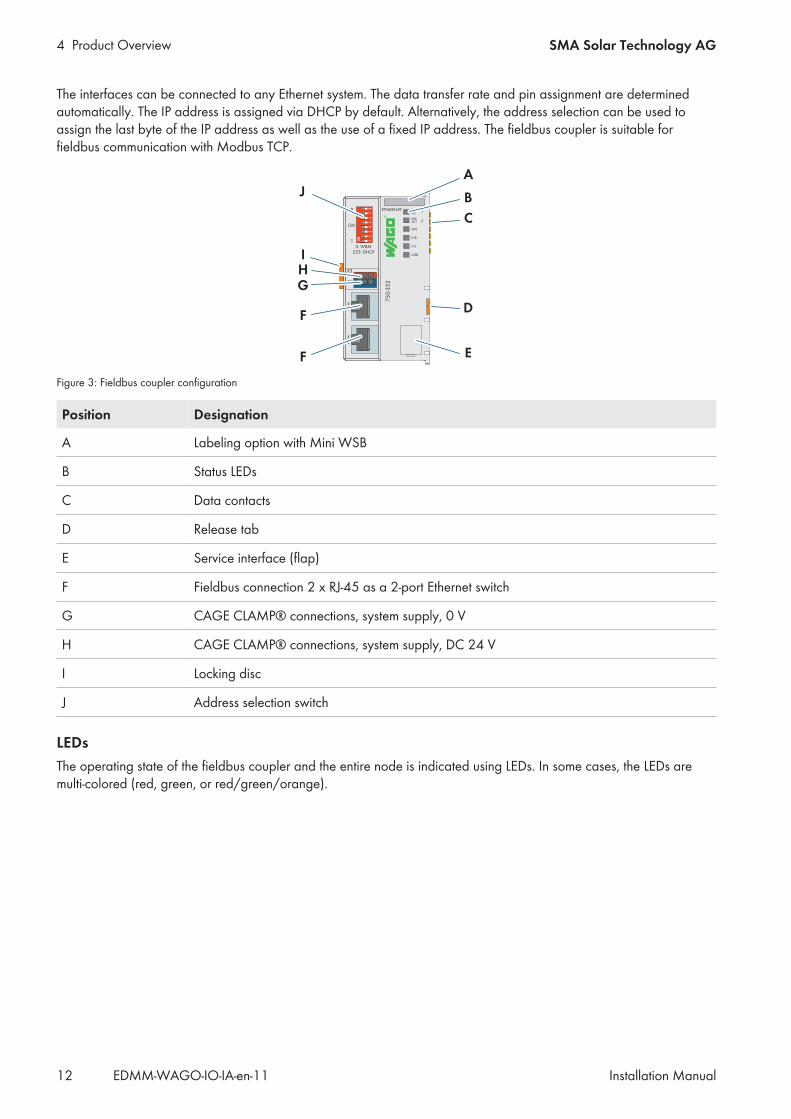
The interfaces can be connected to any Ethernet system. The data transfer rate and pin assignment are determinedautomatically. The IP address is assigned via DHCP by default. Alternatively, the address selection can be used toassign the last byte of the IP address as well as the use of a fixed IP address. The fieldbus coupler is suitable forfieldbus communication with Modbus TCP.
A
B
C
D
E
J
F
F
GHI
Figure 3: Fieldbus coupler configuration
Position Designation
A Labeling option with Mini WSB
B Status LEDs
C Data contacts
D Release tab
E Service interface (flap)
F Fieldbus connection 2 x RJ-45 as a 2-port Ethernet switch
G CAGE CLAMP® connections, system supply, 0 V
H CAGE CLAMP® connections, system supply, DC 24 V
I Locking disc
J Address selection switch
LEDsThe operating state of the fieldbus coupler and the entire node is indicated using LEDs. In some cases, the LEDs aremulti-colored (red, green, or red/green/orange).

4 Product OverviewSMA Solar Technology AG
Installation Manual 13EDMM-WAGO-IO-IA-en-11
For the diagnostics of the different areas for the fieldbus coupler and fieldbus nodes, the LEDs can be divided intocorresponding groups.
A
B
C
D
E
Figure 4: Fieldbus coupler LEDs
Position LED group Color Explanation
Fieldbus status
A LINK ACT 1 green Indicates a connection to the physical net-work at Port 1.
B LINK ACT 2 green Indicates a connection to the physical net-work at Port 2.
C MS Red/green Indicates the node status.
D NS Red/green Indicates the network status.
Node status
E OK Red/green/orange Displays the local bus operation and indi-cates errors with a blink code.
For detailed information on evaluation of the LED statuses(see Section 4.8 "LED Signals", page 16).
4.3 DC 24 V supply moduleThe supply module provides the bus terminals with the corresponding supply potential.
• Max. current via supply module: 10 A• Max. voltage via power contacts: DC 24 V• Max. current via power contacts: DC 10 A

4 Product Overview SMA Solar Technology AG
Installation ManualEDMM-WAGO-IO-IA-en-1114
The supply module provides the 24 V supply potential via the power contacts, the 0 V supply potential, and dasground potential for the field level and for subsequent bus terminals. A green status LED indicates the 24 V operatingvoltage at the power contacts.
DA
B
C
E
F
Figure 5: Supply module connections
Position Connection Designation Designation
A 2 24 V Feed-in: 24 V field supply
D 6 Feed-in: 24 V field supply
B 3 0 V Feed-in: 0 V field supply
E 7 Feed-in: 0 V field supply
C 4 Ground Feed-in: Ground field sup-ply
F 8 Feed-in: Ground field sup-ply
For detailed information on evaluation of the LED statuses (see Section 4.8 "LED Signals", page 16).
4.4 I/O modulesDifferent sensors and actuators are connected to the WAGO-I/O-SYSTEM 750 via the I/O modules. Single-, multiple-,or fine-wire conductors can be connected via the CAGE CLAMP® connections. The terminal bus is responsible forcommunication between the fieldbus coupler/controller and the individual I/O modules. The terminal bus is comprisedof 6 self-cleaning gold-spring contacts. Field supply voltage is used for the voltage supply.The I/O modules receive the 24 V supply potential and the 0 V potential for the field level via the power contacts ofthe respective upstream I/O module or the supply module and also conduct this potential to the downstream I/Omodule.

4 Product OverviewSMA Solar Technology AG
Installation Manual 15EDMM-WAGO-IO-IA-en-11
Status LEDs on the I/O modules indicate the operating state and error-free terminal bus communication via red/greensignals.
A
B
C
D
E
F
C
E
A
B
C
D
E
F
C
E
GG GG
Figure 6: I/O module configuration (example)
Position Designation
A Labeling option with Mini WSB
B Status LEDs
C Data contacts
D CAGE CLAMP® connections
E Power contacts +24 V
F Release tab
G Power contacts 0 V
For detailed information on evaluation of the LED statuses (see Section 4.8 "LED Signals", page 16).
4.5 Bus end terminal 750-600The bus end terminal 750-600 is used to terminate the internal terminal bus of a fieldbus node. This bus terminationensures correct data transmission via terminal bus.The bus end terminal 750-600 is not equipped with any power contacts, CAGE CLAMP® connections or LEDsignaling.
4.6 Hardware address (MAC ID)The WAGO-I/O-SYSTEM 750 has an internationally unique physical address: the MAC ID (Media Access ControlIdentity).The MAC ID is printed on a paper strip with two self-adhesive tear-off labels on the left side of the field bus coupler/controller. The MAC ID has a fixed length of 6 bytes (48 bits) in hexadecimal notation. The first 3 bytes provideinformation about the manufacturer (e.g. 00:30:DE for WAGO). The other 3 bytes contain the consecutive serialnumber of the device hardware.
4.7 Design guidelines and standardsDIN 60204 Electrical equipment of machines
DIN EN 50178 Electronic equipment for use in power installations (replacement for VDE 0160)
EN 60439 Low-voltage switch gear and controlgear assemblies

4 Product Overview SMA Solar Technology AG
Installation ManualEDMM-WAGO-IO-IA-en-1116
4.8 LED Signals
LED signals of the fieldbus couplerThe LEDs indicate the operating state of the fieldbus coupler or the entire fieldbus node. The LEDs are assigned tovarious diagnostic areas in groups.
A
B
C
D
E
Figure 7: Fieldbus coupler LEDs
Position LED group Diagnostic area
A LINK ACT Port 1 Fieldbus status
B LINK ACT Port 2
C MS (module status)
D NS (network status)
E OK Node status
Evaluating the fieldbus statusThe operating state of the communication via fieldbus is indicated via the upper LED group: LINK ACT 1, LINK ACT2, MS, and NS.The two-color LEDs MS (module status) and NS (network status) are only used by the Ethernet/IP protocol. Theindications of these two LEDs comply with the Ethernet/IP specification.
LED status Description Corrective measures
LINK ACT 1, LINK ACT 2
Green The fieldbus node is connected to the physi-cal network.
-
Flashing green The fieldbus node is sending or receiving Eth-ernet telegrams.
-
Off The fieldbus is not connected to the physicalnetwork.
1. Check the fieldbus cable.
MS (module status)
Green The system is working properly. -
Flashing green The system is not yet configured. -
Red The system indicates an error that cannot becorrected.
1. Switch the supply voltage off and onagain to restart the system.
2. If the error is not resolved, pleasecontact WAGO I/O support.

4 Product OverviewSMA Solar Technology AG
Installation Manual 17EDMM-WAGO-IO-IA-en-11
LED status Description Corrective measures
Flashing red/green Self-test -
Off There is no operating voltage for the system. 1. Check the power supply.
NS (network status)
Green The fieldbus node is connected to the physi-cal network.
-
Flashing green The fieldbus node is sending or receiving Eth-ernet telegrams.
-
Red The system has detected a double IP address. 1. Use an IP address that is not already inuse.
Flashing red At least one connection (Modbus TCP or Eth-ernet/IP) has indicated a timeout where thedevice functions as the target.
1. Switch the supply voltage off and onagain to restart the system.
2. Re-establish the connection.
Flashing red/green Self-test -
Off No IP address is assigned to the system. 1. Assign the system a valid IP address(DHCP recommended).
LED signals of the supply module
C
Figure 8: LEDs of the supply module
LED Designation LED status Description
C Status of the operating voltage,power contacts
Off There is no 24 V operating voltage at thepower contacts
Green There is 24 V operating voltage at the powercontacts.

4 Product Overview SMA Solar Technology AG
Installation ManualEDMM-WAGO-IO-IA-en-1118
LED signals of the 4-channel analog input terminal
A
B
C
D
Figure 9: LEDs of the 4-channel analog input terminal
LED Channel Designation LED status Description
A 1 Error AI 1 Off Normal operation
Red Wire break, values outside of the permittedmeasurement range
B 2 Error AI 2 Off Normal operation
Red Wire break, values outside of the permittedmeasurement range
C 3 Error AI 3 Off Normal operation
Red Wire break, values outside of the permittedmeasurement range
D 4 Error AI 4 Off Normal operation
Red Wire break, values outside of the permittedmeasurement range
LED signals of the 4-channel analog output terminal
A
B
Figure 10: LEDs of the 4-channel analog output terminal
LED Designation LED status Description
A Function Off System is not available, lack of or disturbedterminal bus communication
Green System is available and terminal bus commu-nication is not disturbed
B Error Off No error
Red Wire break or inadmissible load combination

4 Product OverviewSMA Solar Technology AG
Installation Manual 19EDMM-WAGO-IO-IA-en-11
LED signals of the 8-channel DC 24 V analog input terminal
A
BCDEFGH
Figure 11: LEDs of the 8-channel DC 24 V digital input terminal
LED Channel Designation LED status Description
A - H 1 - 8 Status DI 1 - 8 Off Input DI 1: signal voltage (0)
Green Input DI 1: signal voltage (1)
LED signals of the 8-channel DC 24 V digital output terminal
A
BCDEFGH
Figure 12: LEDs of the 8-channel DC 24 V digital output terminal
LED Channel Designation LED status Description
A - H 1 - 8 Status DO 1 - 8 Off Output DO 1: signal voltage (0)
Green Output DO 1: signal voltage (1)

4 Product Overview SMA Solar Technology AG
Installation ManualEDMM-WAGO-IO-IA-en-1120
LED signals of the 2/4-channel analog input terminal TempIN
A
B
C
D
E
F
G
H
A
BCD
E
FGH
Figure 13: LEDs of the 2/4-channel analog input terminal TempIN
LED Channel LED status Description
A 1 Off System is not available, lack of or disturbedterminal bus communication (only when thewatchdog timer is enabled)
Green System is available and terminal bus commu-nication is not disturbed
B 2 Off System is not available, lack of or disturbedterminal bus communication (only when thewatchdog timer is enabled)
Green System is available and terminal bus commu-nication is not disturbed
C 1 Off No error
Red Range violated (values too high or too low),short circuit or wire break
D 2 Off No error
Red Range violated (values too high or too low),short circuit or wire break
E 3 Off System is not available, lack of or disturbedterminal bus communication (only when thewatchdog timer is enabled)
Green System is available and terminal bus commu-nication is not disturbed
F 4 Off System is not available, lack of or disturbedterminal bus communication (only when thewatchdog timer is enabled)
Green System is available and terminal bus commu-nication is not disturbed
G 3 Off No error
Red Range violated (values too high or too low),short circuit or wire break

4 Product OverviewSMA Solar Technology AG
Installation Manual 21EDMM-WAGO-IO-IA-en-11
LED Channel LED status Description
H 4 Off No error
Red Range violated (values too high or too low),short circuit or wire break

5 Mounting SMA Solar Technology AG
Installation ManualEDMM-WAGO-IO-IA-en-1122
5 Mounting5.1 Requirements for Mounting
NOTICE
Errors due to changed installation sequenceThe sequence of the I/O modules is fixed. Changing the sequence can impact the function of the product andcause errors.
• Do not change the sequence of the I/O modules.
Permitted and prohibited mounting positions:In addition to horizontal and vertical mounting, all other mounting positions are allowed.
Recommended clearances:Observe the clearances of the entire fieldbus node to neighboring components, cable channels and enclosure/framewalls. The clearances provide space for heat dissipation and assembly or wiring. The clearances to cable channelsalso prevent conducted electromagnetic interference from impacting operation.
35
(1
.37
)3
5 (
1.3
7)
35 (1.37)35 (1.37)
Figure 14: Recommended clearances(Dimensions in mm (in))
Use end clamps for vertical installationFor vertical installation, mount an additional end clamp under the fieldbus node to secure the fieldbus nodeagainst sliding down.
Properties of the mounting railThe WAGO-I/O-SYSTEM 750 can be directly snapped onto a mounting rail in accordance with EN 60175 (TS 35,DIN Rail 35). Please note that mounting rails can have different mechanical and electrical characteristics. To ensureoptimal functioning, the following conditions must be observed: The material must be corrosion-resistant. Mostcomponents have a discharge contact to the mounting rail to ground electromagnetic interference. To avoid anycorrosive effects, this tin-plated mounting rail contact may not form a galvanic element with the material of themounting rail that generates a differential voltage greater than 0.5 V (saline solution of 0.3% at 20°C). The mountingrail must optimally support the electromagnetic compatibility measures integrated into the system and the shielding ofthe I/O module connections. The geometry of the mounting rail may not be altered to ensure that the WAGO-I/O-SYSTEM 750 is held in place security. In particular, when shortening or mounting the carrier rail, it may not be crushed

5 MountingSMA Solar Technology AG
Installation Manual 23EDMM-WAGO-IO-IA-en-11
or bent. The base of the components extends into the profile of the mounting rail. For mounting rails with a height of7.5 mm, mounting points (screw connections) must be countersunk under the node in the mounting rail (countersunkscrew or blind rivet). The metal springs on the bottom of the enclosure must have a low-impedance contact with themounting rail (widest possible contact surface).
Grounding the mounting rail
WARNING
Beware of electrical voltageEnsure a proper electrical connection between the mounting rail and the frame or enclosure in order to guaranteesufficient grounding and to avoid electric shock in the event of an error.
When assembling the frame, the mounting rail must be screwed onto the electrically conductive cabinet frame orenclosure. The frame or enclosure must be grounded. The screw connection also establishes the electrical connection.This grounds the mounting rail.
Insulated assemblyAn assembly is insulated when it is designed so that there is no direct, conductive connection between the cabinetframe or the machine parts and the mounting rail. In this case, the grounding must be established with an electricalconductor in accordance with the valid national safety regulations.
Recommendation for optimal assemblyThe optimal assembly involves a metallic mounting plate with a ground connection that has an electricallyconductive connection to the mounting rail.
5.2 Mounting the product on the mounting railThe WAGO-I/O-SYSTEM 750 comes pre-configured and is directly snapped onto the mounting rail as a completeunit. A tongue and groove system is used for secure positioning and connection. Automatic locking guarantees securehold on the mounting rail.
WARNING
Beware of electrical voltageEnsure a proper electrical connection between the mounting rail contact and the mounting rail in order to guaranteesufficient grounding and to avoid electric shock in the event of an error. Observe the properties of the mounting rail.
Procedure:1. Attach the product to the mounting rail.
• Place the lower edge of the product onto the mounting rail.
1
2

5 Mounting SMA Solar Technology AG
Installation ManualEDMM-WAGO-IO-IA-en-1124
• Press the product down onto the mounting rail from the top.☑ The product snaps audibly into place.
2. Ensure that the product is securely in place.

6 ConnectionSMA Solar Technology AG
Installation Manual 25EDMM-WAGO-IO-IA-en-11
6 Connection6.1 Overview of the Connection Area
D E F G H I J
C
C
BA
K
Figure 15: Overview of the connection area
Position Designation
A DC 24 V system supply
B DC 0 V system supply
C Fieldbus connection 2 x RJ-45 as a 2-port Ethernet switch
D Feed-in: DC 24 V field supply
E Feed-in: DC 0 V field supply
F Feed-in: Ground field supply
G 8x digital input
H 8x digital output
I 2x analog input for PT100 sensors
J 4x analog input 4 mA to 20 mA
K 4x analog output 0 mA to 20 mA
6.2 Connecting the conductor the CAGE CLAMP®The CAGE CLAMP® connection is used to connect the conductor for system supply and supply of the variouscomponents of the I/O modules The CAGE CLAMP® connections are designed for single-, multiple- or fine-wireconductors.
Only connect one conductor per CAGE CLAMP®You may only connect one conductor to each CAGE CLAMP® connection. Multiple individual conductors maynot be connected to one connection. If multiple conductors need to be placed on one connection, connect themusing upstream wiring.
Requirements:☐ Conductor cross-section, single-wire: 0.08 mm² to 2.5 mm² (AWG 28 to AWG 14)☐ Conductor cross-section, fine-wire: 0.25 mm² to 2.5 mm² (AWG 24 to AWG 14)☐ Insulation stripping length: 8 mm to 9 mm (0.315 in to 0.354 in)

6 Connection SMA Solar Technology AG
Installation ManualEDMM-WAGO-IO-IA-en-1126
Procedure:1. Use a suitable tool to unlock the CAGE CLAMP® in the opening
above the connection.
2
13
2. Insert the conductor into the corresponding connection opening.3. To lock the CAGE CLAMP®, remove the tool from the opening.4. Ensure that the conductor is securely in place.
6.3 Information on shieldingThe use of a shielded cable reduces the electromagnetic influences and therefore increases the signal quality. Thismakes it possible to avoid measurement errors, data transmission errors, and disturbances due to overvoltage.Observe the following information:
Connect the cable shield with ground potentialComprehensive shielding is mandatory in order to guarantee the technical specifications in terms of measurementprecision. Establish the connection between the cable shield and ground potential at the opening of the cabinet orenclosure. This diverts any disturbances and keeps them far away from the devices within the cabinet or enclosure.
Use shielded signal cablesUse only shielded cables for analog signals and with devices that are equipped with terminals for the shield. This is theonly way to guarantee that the precision and interference immunity for the respective device can be achieved in theevent of disturbances that affect the signal cable. You can directly connect the shielded cable to some of the I/Omodules. Use the WAGO shield connection system for all others.
Improve the shielding with a large contact areaShielding is improved when the connection between the shield and the ground potential is a low-impedanceconnection. For this purpose, apply the shield over a large area. This is recommended in particular for larger systems inwhich equalizing currents run or high pulsed currents (e.g. triggered by atmospheric discharge) could occur.
Keep data and signal cables away from disturbance sourcesLay data and signal cables separate from all cables that carry three-phase current and other sources of highelectromagnetic emissions (e.g. frequency inverters or drives).
6.4 Functional groundingFunctional grounding increases the interference immunity against electromagnetic influences. The I/O modules areequipped with a mounting rail contact that diverts electromagnetic disturbances away from the mounting rail.The bottom CAGE CLAMP® connections of the supply modules allow for the option to connect a field.side functionalgrounding. The bottom spring contact of the three power contacts makes this potential available to the I/O moduleinstalled to the right. The I/O modules are equipped with a measuring contact that picks up this potential. In terms ofthe functional grounding, this forms a potential group together with the I/O module installed on the left.

6 ConnectionSMA Solar Technology AG
Installation Manual 27EDMM-WAGO-IO-IA-en-11
6.5 Voltage supply terminal
6.5.1 Overcurrent protection
WARNING
Risk of fire due to insufficient overcurrent protectionIn the event of an error, insufficient overcurrent protection may present a fire risk. If the current flow is too high in thecomponents, in the event of an error this could result in excessive overheating.
• Always design the overcurrent protection based on the anticipated power usage.
The fieldbus coupler and supply module are responsible for feeding-in the system and field voltage supply of theWAGO-I/O-SYSTEM 750. For components that work with low voltages, only SELV/PELV voltage sources can be used.To supply multiple components from a single voltage source, this voltage source must be designed in accordance withthe strictest electrical safety requirements based on these components. For components that may only be supplied withvoltage from SELV voltage sources, these requirements are listed in the technical data. Most of the components in theWAGO-I/O-SYSTEM 750 do not have any internal overcurrent protection. For this reason, a suitable overcurrentprotection must be installed externally for every feed-in, for example using fuses. The maximum permitted current islisted in the technical data of the installed components.
6.5.2 Potential isolationThere are three galvanically isolated potential groups in the WAGO-I/O-SYSTEM 750:
• Galvanically isolated fieldbus interface• Electronics of the fieldbus coupler and the I/O modules (local bus)• All I/O modules are equipped with galvanic isolation between the system electronics (local bus, logic) and the
field-side electronics. This isolation is installed per channel for some digital input modules and analog inputmodules. For further information, see the product specifications of the individual I/O modules.
6.5.3 System supply
NOTICE
Damage to the electronicsWithout overvoltage protection, the electronics can be damaged.
• Ensure that the power supply is adequately protected. If you use a fuse for overcurrent protection of the systemsupply, use a fuse with a maximum of 2 A for this purpose.
NOTICE
Damage due to exceeding the maximum current at the power contacts.• Please ensure that the maximum current that can run through the power contacts does not exceed 10 A.

6 Connection SMA Solar Technology AG
Installation ManualEDMM-WAGO-IO-IA-en-1128
The WAGO-I/O-SYSTEM 750 requires a 24 V direct voltage for the system supply. The voltage is fed in via the supplymodule and is protected against reverse polarity.
��� ��
GND+24 V DC
+24 V DC (-15 % / +20 %)0 V
Figure 16: System supply overview
The fed in 24 V direct voltage supplies all internal system components, e.g. the electronics of the fieldbus coupler/controller, the fieldbus interface and the I/O modules, via the local bus (5 V system voltage). The 5 V system voltage isgalvanically connected to the 24 V system supply.
6.5.4 Power supply designRegulated power supply unitsStable grid supply cannot always be guaranteed anywhere all the time. For this reason, regulated power supplyunits must be used in order to guarantee the quality of the supply voltage.
Calculation of the power supply unit output (at DC 24 V):The internal current consumption for each I/O module is specified in the technical data of the I/O module. Todetermine overall consumption, the values of all of the modules in the node are added up.
Example:
Fieldbus coupler: 280 mA
DI: 37 mA
DO: 10 mA + output load of all channels (max. 500 mA/channel)
TempIN (PT100): 10 mA
AI: 15 mA
AO: 120 mA (80 mA for 4 x 20 mA outputs + efficiency + internal power supply)
Total Approx. 1.5 A at 24 V (with a maximum load of 120 mA per digital out-put channel)
With higher loads at the digital outputs, it is correspondingly greater.

6 ConnectionSMA Solar Technology AG
Installation Manual 29EDMM-WAGO-IO-IA-en-11
6.5.5 Connecting different components at the I/O modulesFive I/O modules are available for connecting different components:
• 8-channel DC 24 V digital input terminal• 8-channel DC 24 V digital output terminal• 2/4-channel analog input terminal 2 TempIN (PT100)• 4-channel analog input terminal 4 mA to 20 mA• 4-channel analog output terminal 0 mA to 20 mA
6.5.5.1 8-channel DC 24 V digital input terminalThe 8-channel DC 24 V digital input terminal is comprised of binary control signals from the field area (e.g. fromsensors, transmitters, switches or proximity switches).The bus terminal has 8 input channels and allows for direct connection of sensors with 2-conductor technology(potential-free contact). The sensors are connected to the CAGE CLAMP® connections DI 1 and 24 V to DI8 and24 V.For interference suppression, each input channel is equipped with an RC filter with a time constant of 3.0 ms. Theinputs of the us terminal are positive switching. If the 24 V potential for the field supply is switched on an inputconnection, the signal state of the corresponding input channel is “high”. Green status LEDs indicate the respectivesignal state per channel.For detailed information on evaluation of the LED statuses (see Section 4.8 "LED Signals", page 16).
A
B
C
DE
F
GH
I
J
K
LM
N
OP
Figure 17: Connections of the 8-channel DC 24 V digital input terminal
Position Channel Connec-tion
Designation Designation
A - H 1 - 8 1 - 8 DI 1- 8 Digital input 1 - 8: signal voltage
I - P 9 - 16 24 V Digital input 1 - 8: sensor supply +24 V

6 Connection SMA Solar Technology AG
Installation ManualEDMM-WAGO-IO-IA-en-1130
+ 24 V
0 V
DI
10 nF DI
10 nF
24 V
24 V
24 V
24 V
24 V
24 V
24 V
DI 1
DI 2
DI 3
DI 4
DI 5
DI 6
DI 7
DI 8
2
3
4
5
6
7
8
9
10
11
12
13
14
15
16
24 V1
+24 V
0 V
Figure 18: Circuitry of the 8-channel DC 24 V digital input terminal
1 Dig In
3 Dig In
5 Dig In
7 Dig In
2 Dig In
4 Dig In
6 Dig In
8 Dig In
Figure 19: Example connection of the 8-channel DC 24 V digital input terminal
6.5.5.2 8-channel DC 24 V digital output terminalThe 8-channel DC 24 V digital output terminal transmits binary control signals from the automation device to theconnected actuators (e.g. magnet valves, contactors, transmitters, relays or other electrical appliances).The bus terminal has 8 output channels and allows for direct connection of actuators with 2-conductor technology.These are not outputs in the form of potential-free contacts, but rather actively switched 24 V signals.

6 ConnectionSMA Solar Technology AG
Installation Manual 31EDMM-WAGO-IO-IA-en-11
For detailed information on evaluation of the LED statuses (see Section 4.8 "LED Signals", page 16).
A
B
C
DE
F
GH
I
J
K
LM
N
OP
Figure 20: Connections of the 8-channel DC 24 V digital output terminal
Position Channel Connec-tion
Designation Designation
A - H 1 - 8 1 - 8 DO 1- 8 Digital output 1 - 8: signal voltage
I - P 9 - 16 0 V Digital output 1 - 8: field supply 0 V
0 V
0 V
0 V
0 V
0 V
0 V
0 V
DO
DO
DO
DO
DO
DO
DO
DO
2
3
4
5
6
7
8
9
10
11
12
13
14
15
16
0 V1
+24 V
0 V
+ 24 V
0 V
DO
10 nF
10 nF
270 pF
Figure 21: Circuitry of the 8-channel DC 24 V digital output terminal
Dig GND2 Dig Out +
Dig GND1 Dig Out +
Dig GND 3 Dig Out +
Dig GND 5 Dig Out +
Dig GND7 Dig Out +
Dig GND4 Dig Out +
Dig GND6 Dig Out +
Dig GND8 Dig Out +
Figure 22: Example connection of the 8-channel DC 24 V digital output terminal

6 Connection SMA Solar Technology AG
Installation ManualEDMM-WAGO-IO-IA-en-1132
6.5.5.3 2/4-channel analog input terminal (TempIN)The 2/4-channel analog input terminal (TempIN) evaluates two PT100 sensors. The resistance values are converted totemperature values. A microprocessor in the bus terminal linearizes the measured resistance values and converts theminto a numerical value that is proportional to the temperature of the selected resistance sensor.A green status LED and a rote error LED for each channel indicate either the operating state, a short circuit, a wirebreak, or values outside the range of measurement. PT100 sensors are connected to the CAGE CLAMP® connections+R1/-R1 to +R4/-R4.For detailed information on evaluation of the LED statuses (see Section 4.8 "LED Signals", page 16).
C
D
A
B F
E
G
H
Figure 23: Connections of the 2/4-channel analog input terminal (TempIN)
Position Connection Designation Designation
A 1 +R1
B 2 -R1
C 3 +R3
D 4 -R3
E 5 +R2
F 6 -R2
G 7 +R4
H 8 -R4
+R 1
+R 3
+R 2
+R 4
24 V
0 V
1 5
2 6
3 7
4 8
-R 1 -R 2
-R 4-R 3
-R
+R
10 nF
100 nF
MUX AD logic
function
error
Figure 24: Circuitry of the 2/4-channel analog input terminal (TempIN)

6 ConnectionSMA Solar Technology AG
Installation Manual 33EDMM-WAGO-IO-IA-en-11
-R3
R 1
-R4
R 2
+R3 +R4
-R2
+R2+R1
-R1
Figure 25: Example connection of the 2/4-channel analog input terminal (TempIN)
6.5.5.4 4-channel analog input terminal 4 mA to 20 mAThe 4-channel analog input terminal 4 mA to 20 mA has four input channels for field signals and processes signals ofstandard size from 4 mA to 20 mA. The input signal is galvanically isolated from the system level with a 12-bitresolution. The sensors are connected to the CAGE CLAMP® connections AI 1 and ground or AI 2, AI 3, AI 4 andground. The ground connections for all 4 channels are connected to one shared 0 V ground potential.A red LED indicates a wire break or a value outside of the measurement range for each channel. The internal systemvoltage is used for voltage supply.For detailed information on evaluation of the LED statuses (see Section 4.8 "LED Signals", page 16).
C
D
A
B F
E
G
H
Figure 26: Connections of the 4-channel analog input terminal 4 mA to 20 mA
Position Channel Connec-tion
Designation Designation
A 1 1 AI 1 Analog input 1: signal voltage
B 2 Ground Analog input 1: ground
C 2 3 AI 3 Analog input 3: signal voltage
D 4 Ground Analog input 3: ground
E 3 5 AI 2 Analog input 2: signal voltage
F 6 Ground Analog input 2: ground
G 4 7 AI 4 Analog input 4: signal voltage
H 8 Ground Analog input 4: ground

6 Connection SMA Solar Technology AG
Installation ManualEDMM-WAGO-IO-IA-en-1134
AI 1
AI 3
AI 2
AI 4
24 V
0 V
1 5
2 6
3 7
4 8
AO
10 nF
270 pF
AD
ground
groundground
logic
error
Figure 27: Circuitry of the 4-channel analog input terminal 4 mA to 20 mA
Figure 28: Example connection of the 4-channel analog input terminal 4 mA to 20 mA
6.5.5.5 4-channel analog output terminal 0 mA to 20 mAThe 4-channel analog output terminal 0 mA to 20 mA has four output channels and generates signals that must bestrictly restricted to 4 mA to 20 mA by an internal scaling installed in Data Manager M. This allows for direct wiring offour 2-conductor actuators on the bus terminal. The actuators are connected to the CAGE CLAMP® connections AO 1and ground or AO 2, AO 3, AO 4 and ground. The channels have one shared ground potential.A green LED indicates the operating state and error-free terminal bus communication. A red error LED indicates a shortcircuit or an overload.

6 ConnectionSMA Solar Technology AG
Installation Manual 35EDMM-WAGO-IO-IA-en-11
For detailed information on evaluation of the LED statuses (see Section 4.8 "LED Signals", page 16).
C
D
A
B F
E
G
H
Figure 29: Connections of the 4-channel analog output terminal 0 mA to 20 mA
Position Channel Connec-tion
Designation Designation
A 1 1 AO 1 Analog output 1: signal voltage
B 2 Ground Analog output 1: ground
C 2 3 AO 3 Analog output 3: signal voltage
D 4 Ground Analog output 3: ground
E 3 5 AO 2 Analog output 2: signal voltage
F 6 Ground Analog output 2: ground
G 4 7 AO 4 Analog output 4: signal voltage
H 8 Ground Analog output 4: ground
AO
10 nF
AD
IU
10 nF
10 nF
0 V
24 V
0 V
AO 1
0 V
AO 3
AO 2
AO 4
24 V
0 V
1 5
2 6
3 7
4 8
0 V
logic
function
error
Figure 30: Circuitry of the 4-channel analog output terminal 0 mA to 20 mA

6 Connection SMA Solar Technology AG
Installation ManualEDMM-WAGO-IO-IA-en-1136
Figure 31: Example connection of the 4-channel analog output terminal 0 mA to 20 mA
6.5.6 Connection to Data Manager M
NOTICE
Damage to the product due to incorrect connection• Only use devices with an Ethernet/RJ-45 connection in LANs.• Never connect these devices with telecommunications networks such as with analog or ISDN telephone
networks.
Two RJ-45 connectors are used to establish the connection to Data Manager M. The RJ-45 connectors are connectedto the fieldbus coupler via an integrated network switch. The integrated network switch words in store-and-forwardmode and supports a data transfer rate of 10/100 Mbit for every port as well as the full duplex, half duplex, and autonegotiation transfer modes.The RJ-45 jacks are wired in accordance with the requirements for 100BASE-TX. In accordance with the Ethernetstandard, a Cat 5e twisted-pair cable must be used as the connecting cable. S-UTP (screened unshielded twisted pair)and STP (shielded twisted pair) cables with a maximum segment length of 100 m can be used. The connection point isdesigned so that the system can be installed in an 80 mm-high switch cabinet is possible after the connector is pluggedin.
A B C D E F G H
Figure 32: Pin assignment of the fieldbus connection
Position Signal Designation
A TD + Transmit data +
B TD - Transmit data -
C RD + Receive data +

6 ConnectionSMA Solar Technology AG
Installation Manual 37EDMM-WAGO-IO-IA-en-11
Position Signal Designation
D Not assigned
E Not assigned
F RD - Receive data -
G Not assigned
H Not assigned

7 Commissioning SMA Solar Technology AG
Installation ManualEDMM-WAGO-IO-IA-en-1138
7 CommissioningFor commissioning, you must establish a connection between the WAGO-I/O-SYSTEM 750 and Data Manager M.
7.1 Connecting the WAGO-I/O-SYSTEM 750 with Data Manager MReserving the IP addressIf the communication between the WAGO-I/O-SYSTEM 750 and Data Manager M works properly, the IPaddress must be permanently reserved for the WAGO-I/O-SYSTEM 750 in DHCP. If you have any questions,contact your administrator.
Requirements:☐ The fieldbus node is mounted on the TS 35 mounting rail.☐ A 24 V supply voltage is connected to the supply module.☐ A router is connected to the system and, ideally, has Internet access.☐ There is a DHCP server in your network. If you have any questions, contact your administrator.☐ The WAGO-I/O-SYSTEM 750 is connected with Data Manager M via the Ethernet interface (RJ-45). Both
Ethernet ports on the WAGO-I/O-SYSTEM 750 and on Data Manager M can be used for this purpose.
Procedure:1. Check whether the address selection switch is set to the value 255 (position of the address switch: 1111 1111).
The address selection switch is inactive in this position and the setting configured in the fieldbus coupler is used.This means that the DHCP server is responsible for assigning the IP address.
2. Switch the operating voltage on.
Figure 33: Address selection switch
After you have switched on the operating voltage, initialization of the fieldbus coupler begins. The fieldbus couplerdetermines the I/O module constellation and generates the corresponding process image. While it is booting up, theI/O LED flashes red. If the I/O LED lights up green after a short time, the fieldbus coupler is ready for operation.If an error occurs while the fieldbus coupler is booting up, the I/O LED will flash red and communicate an error codeby blinking. After the fieldbus coupler boots up, if the I/O LED flashes red 6 times, signaling error code 6, and thenflashes red 4 times, signaling error argument 4, this indicates that no IP address has been assigned yet.
7.2 Assigning the IP addressYou have 4 options for assigning the IP address:
• Permanently assigning the IP address with the option “use IP from EEPROM”• Assigning the IP address with the address selection switch• Assigning the IP address with the “WAGO Ethernet Settings” (statistic IP address via the serial communication
interface)• Dynamically assigning the IP address with DHCP

7 CommissioningSMA Solar Technology AG
Installation Manual 39EDMM-WAGO-IO-IA-en-11
Permanently assigning the IP address with the option “use IP from EEPROM”The IP saved in EEPROM must be used for permanent address assignment.In order for the IP address received via DHCP to be stored permanently in the fieldbus coupler, you must select theoption “use IP from EEPROM”. When you select this option, the static address in EEPROM is automatically usedas the IP address. You can switch to the option “use IP from EEPROM” in the web-based management system.
Assigning the IP address with the address selection switchUsing the address selection switch, you can set the Host ID, e.g. the last byte of the IP address, which is entered in theweb-based management system on the TCP/IP page under the entry “Switch IP address”, to a binary coded valuebetween 1 and 254.
Assigning the IP address with the “WAGO Ethernet Settings” (statistic IP address via the serialcommunication interface)Use the address selections witch to set the value 0 (position of the address switch: 0000 0000). The address selectionswitch is inactive in this position and the settings of the web-based management system or the “WAGO EthernetSettings” will be applied.
Figure 34: Address selection switch
7.3 Configuring the WAGO-I/O-SYSTEM 750 via Data Manager M userinterface
7.3.1 Device registrationRequirements:☐ The fieldbus node is mounted on the TS 35 mounting rail.☐ A 24 V supply voltage is connected to the supply module.☐ A router is connected to the system and, ideally, has Internet access.☐ The WAGO-I/O-SYSTEM 750 is connected with Data Manager M via the Ethernet interface (RJ-45). Both
Ethernet ports on the WAGO-I/O-SYSTEM 750 and on Data Manager M can be used for this purpose.
Procedure:1. Log in to the user interface of Data Manager M.2. Select the menu item Device administration in the menu Configuration.3. Select the button to register a new Modbus device.
4. Select Modbus devices and confirm with [Next].

7 Commissioning SMA Solar Technology AG
Installation ManualEDMM-WAGO-IO-IA-en-1140
5. Under Modbus profile, select the profile WAGO I/Oextension bundle (0-20 mA output) and confirm with [Next].
6. Select the device, enter the Device name and Serial number.
7. Click on [Save].8. Check that the newly registered WAGO-I/O-SYSTEM 750 is
included in the device overview.
7.3.2 Selecting the device for configuring sensorsRequirements:☐ The WAGO-I/O-SYSTEM 750 is in operation and registered as a new Modbus device in Data Manager M.☐ During configuration, a signal from 4 mA to 20 mA must be present at the analog inputs.
Procedure:1. Log in to the user interface of Data Manager M.2. Select the WAGO-I/O-SYSTEM 750 in the list view in the
SELECT DEVICE menu under the name that was assigned duringdevice configuration.
7.3.3 Defining the input and function for configuring sensorsThe I/O configuration menu item allows you to add and configure I/O channel inputs and I/O channel outputs.
Requirements:☐ The WAGO-I/O-SYSTEM 750 is in operation and registered as a new Modbus device in Data Manager M.☐ The WAGO-I/O-SYSTEM 750 is selected.

7 CommissioningSMA Solar Technology AG
Installation Manual 41EDMM-WAGO-IO-IA-en-11
Procedure:1. Log in to the user interface of Data Manager M.2. Select the I/O configuration menu item in the Configuration
menu.
3. Click the button to configure a new channel.
4. Determine whether the channel is an input or output channel.
5. Select the function of the channel.

7 Commissioning SMA Solar Technology AG
Installation ManualEDMM-WAGO-IO-IA-en-1142
Figure 35: Example configuration: solar irradiation

7 CommissioningSMA Solar Technology AG
Installation Manual 43EDMM-WAGO-IO-IA-en-11
Figure 36: Example configuration: wind speed

7 Commissioning SMA Solar Technology AG
Installation ManualEDMM-WAGO-IO-IA-en-1144
Figure 37: Example configuration: temperature input
6. Fill out the input fields and confirm with [Save].7. Select the Instantaneous values menu item in the Monitoring
menu and check the information entered. The newly addedchannel should now appear in the list and display the currentvalues.
7.3.4 Defining the channel and scaling for grid management servicesOne analog input channel should be created as the setpoint for the active power limit [% of the nominal PV systempower] and one analog output channel should be created as the actual value of the power at the point ofinterconnection [W].

7 CommissioningSMA Solar Technology AG
Installation Manual 45EDMM-WAGO-IO-IA-en-11
Requirements:☐ The WAGO-I/O-SYSTEM 750 is in operation and registered as a new Modbus device in Data Manager M.
Procedure:1. Log in to the user interface of Data Manager M.2. Select the WAGO-I/O-SYSTEM 750 in the list view in the SELECT DEVICE menu under the name that was
assigned during device configuration.3. Select the I/O configuration menu item in the Configuration menu.4. Click the button to configure a new channel.5. Select Input.

7 Commissioning SMA Solar Technology AG
Installation ManualEDMM-WAGO-IO-IA-en-1146
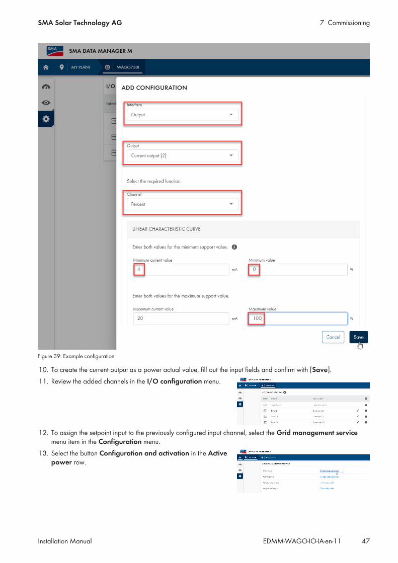
Figure 38: Example configuration
6. To create the channel as a setpoint source and as a percentage, select the Current input input and the Percentchannel.
7. Fill out the input fields and confirm with [Save].8. Select the I/O configuration menu item in the Configuration menu.9. Select Output.
7 CommissioningSMA Solar Technology AG
Installation Manual 47EDMM-WAGO-IO-IA-en-11
Figure 39: Example configuration
10. To create the current output as a power actual value, fill out the input fields and confirm with [Save].11. Review the added channels in the I/O configuration menu.
12. To assign the setpoint input to the previously configured input channel, select the Grid management servicemenu item in the Configuration menu.
13. Select the button Configuration and activation in the Activepower row.

7 Commissioning SMA Solar Technology AG
Installation ManualEDMM-WAGO-IO-IA-en-1148
Figure 40: Example configuration
14. Fill out the input fields and click [Next].15. Follow the installation assistant steps and make the settings according to the specifications required by the grid
operator and laid down in the standards.16. Click on [Save].17. To assign the actual value output at the previously configured output channel, select the Grid management
service menu item in the Configuration menu.18. Click the button Go to configuration in the Assigning analog
outputs row.
19. Click the button to create a new output channel.

7 CommissioningSMA Solar Technology AG
Installation Manual 49EDMM-WAGO-IO-IA-en-11
20. Select the Output channel that was previously configured in theI/O configuration and confirm with [Save].
21. To assign additional actual values to the corresponding output channels, click the button.
7.3.5 Displaying measured values locally on the Data Manager M Modbusserver
One analog input channel should be created as the setpoint for the active power limit [% of the nominal PV systempower] and one analog output channel should be created as the actual value of the power at the point ofinterconnection [W].
Requirements:☐ The Modbus server is enabled.☐ The I/O channel inputs and I/O channel outputs are configured and assigned to the corresponding sensors.
Procedure:1. Log in to the user interface of Data Manager M.2. Select Data Manager M in the list view in the SELECT DEVICE menu.3. Select the External communication menu item in the Configuration menu.4. Click the button to configure the Modbus server.
5. Click the button to add a sensor.

7 Commissioning SMA Solar Technology AG
Installation ManualEDMM-WAGO-IO-IA-en-1150
6. Select the settings for the device and confirm with [Save].
7. Repeat the process to add additional sensors such as, for example, for cell temperature.8. Check the added sensors in the SENSOR ASSIGNMENT menu.
9. Click on [Save].

8 TroubleshootingSMA Solar Technology AG
Installation Manual 51EDMM-WAGO-IO-IA-en-11
8 Troubleshooting
Fieldbus failureA fieldbus failure occurs if, for example, the master is switched off or the bus cable is interrupted. An error in the mastercan also result in a fieldbus failure.
Local bus errorA local bus error is displayed via the I/O LED.The I/O LED flashes red: In the event of a local bus error, the fieldbus coupler generates an error message (error codeand error argument). A local bus error occurs, for example, when an I/O module is unplugged. If this error occursduring operation, the output modules act like a local bus stop. Once the local bus error has been remedied, switch thefieldbus node off and on again to restart the transmission of process data.For detailed information on evaluation of the LED statuses (see Section 4.8 "LED Signals", page 16).

9 Contact SMA Solar Technology AG
Installation ManualEDMM-WAGO-IO-IA-en-1152
9 ContactDeutschlandÖsterreichSchweiz
SMA Solar Technology AGNiestetalSunny Boy, Sunny Mini Central,Sunny Tripower, Sunny Highpower:+49 561 9522‑1499Monitoring Systems, SMA EV Charger:+49 561 9522‑2499Hybrid Controller:+49 561 9522-3199Sunny Island, Sunny Boy Storage,Sunny Backup:+49 561 9522-399Sunny Central, Sunny Central Storage: +49 561 9522-299SMA Online Service Center:www.SMA-Service.com
BelgienBelgiqueBelgiëLuxemburgLuxembourgNederland
SMA Benelux BVBA/SPRLMechelen +32 15 286 730for Netherlands: +31 30 2492 000SMA Online Service Center:www.SMA-Service.com
ČeskoMagyarországSlovensko
SMA Service Partner TERMS a.s +420 387 6 85 111SMA Online Service Center:www.SMA-Service.com
Türkiye SMA Service Partner DEKOMTelekomünikasyon A. Ş +90 24 22430605SMA Online Service Center:www.SMA-Service.com
France SMA France S.A.S.Lyon +33 472 22 97 00SMA Online Service Center:www.SMA-Service.com
ΕλλάδαΚύπρος
SMA Service Partner AKTOR FM.Αθήνα +30 210 8184550SMA Online Service Center:www.SMA-Service.com
EspañaPortugal
SMA Ibérica Tecnología Solar, S.L.U.Barcelona +34 935 63 50 99SMA Online Service Center:www.SMA-Service.com
United Kingdom SMA Solar UK Ltd.Milton Keynes +44 1908 304899SMA Online Service Center:www.SMA-Service.com
Italia SMA Italia S.r.l.Milano +39 02 8934-7299SMA Online Service Center:www.SMA-Service.com
Australia SMA Australia Pty Ltd.SydneyToll free for Australia:1800 SMA AUS(1800 762 287)International: +61 2 9491 4200
United ArabEmirates
SMA Middle East LLCAbu Dhabi +971 2234 6177SMA Online Service Center:www.SMA-Service.com
India SMA Solar India Pvt. Ltd.Mumbai +91 22 61713888

9 ContactSMA Solar Technology AG
Installation Manual 53EDMM-WAGO-IO-IA-en-11
ไทย Service Partner for String inverter:Solar Power Engineering Co., Ltd.333/7,8,9 United Tower Building 4thfloor.Soi Sukhumvit 55 (Thonglor 17), Klong-ton Nua, Wattana,10110 Bangkok, Thailand +66 [email protected] Partner for Utility:Tirathai E & S Co., Ltd516/1 Moo 4, Bangpoo Industrial Es-tateSukhumvit Road, T. Praksa, A. Muang10280 Samutprakarn, Thailand +63 [email protected]
대한민국 Enerone Technology Co., Ltd4th Fl, Jungbu Bldg, 329,Yeongdong-daero, Gangnam-gu,Seoul, 06188, Korea +82-2-520-2666
ArgentinaBrasilChilePerú
SMA South America SPASantiago de Chile +562 2820 2101
South Africa SMA Solar Technology South AfricaPty Ltd.Cape Town08600SUNNY(08600 78669)International: +27 (0)21 826 0699SMA Online Service Center:www.SMA-Service.com
Other coun-tries
International SMA Service LineNiestetal00800 SMA SERVICE(00800 762 7378423)SMA Online Service Center:www.SMA-Service.com
United States SMA Solar TechnologyAmerica LLCRocklin, CA
Toll free for USA and US Territories+1 877-MY-SMATech (+1 877-697-6283)International: +1 916 625-0870
Canada SMA Solar TechnologyCanada Inc.Mississauga
Toll free for Canada / Sans frais pour le Canada :+1 877-MY-SMATech (+1 877-697-6283)
México SMA Solar Technology deMéxicoMexico City
Internacional: +1 916 625-0870

www.SMA-Solar.com