w-next3 df
TRANSCRIPT

Data Book T_wNEXT3DF_1220_EN
w-NEXT3 DF 8 - 15 kW Air conditioners for IT Cooling with DUAL FLUID system for chilled water feeding.
The pictures of the units are indicative and may vary depending on the model
• For small Data Room
• Bottom or top air delivery
• Dual Fluid system with additional cooling coil
• Plug-fan with EC electric motors
• Air suction temperature up to 45°C
• Total front accessibility
• LAN connection up to 15 units
•
rcitcooling.com

w-NEXT3 DF
T_wNEXT3DF_1220_EN
DATA BOOK
2
INDEX
CERTIFICATIONS ........................................................................................................................................................................................................................ 4 GENERAL CHARACTERISTICS .................................................................................................................................................................................................. 4 THE SERIES ................................................................................................................................................................................................................................. 6 PRODUCT FEATURES AND BENEFITS ..................................................................................................................................................................................... 6 MODEL IDENTIFICATION ............................................................................................................................................................................................................ 6 STORING TEMPERATURE .......................................................................................................................................................................................................... 6 WORKING LIMITS ........................................................................................................................................................................................................................ 7 LIMIT OF CHILLED WATER TEMPERATURE AT THE UNIT’S INLET ....................................................................................................................................... 7 MAIN COMPONENTS ................................................................................................................................................................................................................... 8 OPTIONAL ACCESSORIES ......................................................................................................................................................................................................... 9 TECHNICAL DATA – UNDER / OVER VERSION ...................................................................................................................................................................... 11 DUAL FLUID SYSTEM ................................................................................................................................................................................................................ 12 ACTIVE REDUNDANCY ............................................................................................................................................................................................................. 13 HYDRAULIC CIRCUIT ................................................................................................................................................................................................................ 13 2-WAY BALL VALVE FOR CHILLED WATER FLOW CONTROL (MAIN CIRCUIT AND DUAL FLUID CIRCUIT) ................................................................... 14 WATER QUALITY OF THE HYDRAULIC CIRCUITS ................................................................................................................................................................. 14 ANTIFREEZE MIXTURES .......................................................................................................................................................................................................... 15 ACOUSTIC DATA ....................................................................................................................................................................................................................... 15 ELECTRICAL DATA .................................................................................................................................................................................................................... 16 MICROPROCESSOR CONTROL SYSTEM ............................................................................................................................................................................... 17 OPTIONAL ACCESSORIES: P122 - BOTTOM AIR INTAKE+BLIND PANELS ......................................................................................................................... 19 OPTIONAL ACCESSORIES: B264 – BACK AIR INTAKE+BLIND PANELS .............................................................................................................................. 19 OPTIONAL ACCESSORIES: B821 – COOLING COIL HYDROPHILIC TREATMENT .............................................................................................................. 20 OPTIONAL ACCESSORIES: A547 / A548 - CONSTANT FLOW / CONSTANT PREVALENCE .............................................................................................. 20 OPTIONAL ACCESSORIES: B792 – 400/3+N/50 POWER SUPPLY ........................................................................................................................................ 20 OPTIONAL ACCESSORIES: B794 – 230/1/60 POWER SUPPLY ............................................................................................................................................ 20 OPTIONAL ACCESSORIES: B795 – 230/3/60 POWER SUPPLY ............................................................................................................................................. 20 OPTIONAL ACCESSORIES: B796 – 380/3+N/60 POWER SUPPLY ....................................................................................................................................... 20 OPTIONAL ACCESSORIES: B798 – 460/3+N/60 POWER SUPPLY ........................................................................................................................................ 20 OPTIONAL ACCESSORIES: P091 – BACKUP MODULE CONTROLLER ................................................................................................................................ 20 OPTIONAL ACCESSORIES: 383 – NUMBERED WIRINGS + UK REQUESTS ....................................................................................................................... 21 OPTIONAL ACCESSORIES: A471 – SERIAL CARD RS485..................................................................................................................................................... 21 OPTIONAL ACCESSORIES: A472 – SERIAL CARD RS232..................................................................................................................................................... 21 OPTIONAL ACCESSORIES: A473 – ETHERNET CARD .......................................................................................................................................................... 21 OPTIONAL ACCESSORIES: A474 – SERIAL CARD LON ........................................................................................................................................................ 21 OPTIONAL ACCESSORIES: B811 - AIR FLOW LOSS ALARM ................................................................................................................................................ 21 OPTIONAL ACCESSORIES: A35B – GRAPHIC DISPLAY “EVOLUTION TOUCH” ................................................................................................................. 22 OPTIONAL ACCESSORIES: A381 - DRAIN PUMP ................................................................................................................................................................... 23 OPTIONAL ACCESSORIES: A491 - WATER LEAKAGE DETECTOR ...................................................................................................................................... 24 OPTIONAL ACCESSORIES: A492 – WATER LEAKAGE DETECTOR + ADDITIONAL SENSOR ........................................................................................... 24 OPTIONAL ACCESSORIES: A501 - CLOGGED FILTERS........................................................................................................................................................ 24 OPTIONAL ACCESSORIES: A511 – SMOKE DETECTOR ....................................................................................................................................................... 24 OPTIONAL ACCESSORIES: A521 – FIRE DETECTOR ............................................................................................................................................................ 25 OPTIONAL ACCESSORIES: 5891 – CONTROL UNIT VIA KIPLINK ........................................................................................................................................ 25 OPTIONAL ACCESSORIES: A822 – ADAPTIVE SET-POINT................................................................................................................................................... 26 OPTIONAL ACCESSORIES: P141 – ANALOGUE SET-POINT COMPENSATION .................................................................................................................. 26 OPTIONAL ACCESSORIES: A842 - NETWORK ANALYZER ................................................................................................................................................... 26 OPTIONAL ACCESSORIES: A812 – FREE-COOLING DIRECT CONTROL ............................................................................................................................ 26 OPTIONAL ACCESSORIES: A791 – AIR TEMPERATURE CONTROL ON AIR RETURN ...................................................................................................... 26 OPTIONAL ACCESSORIES: A663 – 0-10V 3-WAY VALVE ...................................................................................................................................................... 27 OPTIONAL ACCESSORIES: A431 - ELECTRIC HEATERS...................................................................................................................................................... 28

w-NEXT3 DF
T_wNEXT3DF_1220_EN
DATA BOOK
3
OPTIONAL ACCESSORIES: 4301 – STEAM HUMIDIFIER....................................................................................................................................................... 29 OPTIONAL ACCESSORIES: P051 - DEHUMIDIFICATION ....................................................................................................................................................... 30 OPTIONAL ACCESSORIES: P161 – T/RH AIR INTAKE SENSOR ........................................................................................................................................... 31 OPTIONAL ACCESSORIES: 4666 – EXTERNAL AIR PROBE ................................................................................................................................................. 31 OPTIONAL ACCESSORIES: P071 – REMOTE T/RH PROBE .................................................................................................................................................. 31 OPTIONAL ACCESSORIES: P113 - DUAL POWER SUPPLY .................................................................................................................................................. 31 OPTIONAL ACCESSORIES: P084 – EPM10 50% AIR FILTERS ............................................................................................................................................... 32 OPTIONAL ACCESSORIES: A532 – DAMPER WITH SPRING RETURN ................................................................................................................................ 33 OPTIONAL ACCESSORIES: P011 … P034 - SUPPLY / INTAKE AIR PLENUM ...................................................................................................................... 34 OPTIONAL ACCESSORIES: P034 – INTAKE FREE-COOLING PLENUM ............................................................................................................................... 39 OPTIONAL ACCESSORIES: P041 / P042 / P043 - SUPPORT FRAME ................................................................................................................................... 41 OPTIONAL ACCESSORIES: A272 – CL.A1 (EN13501-1) INSULATION .................................................................................................................................. 41 OPTIONAL ACCESSORIES: P151 – LOWERED DISPLAY FOR UNDER ................................................................................................................................ 42 OPTIONAL ACCESSORIES: P101 - ANTI-SEISMIC FIXING KIT.............................................................................................................................................. 42 OPTIONAL ACCESSORIES: T500000310 / 311 - CONDENSATE TRAY (ONLY UNDER VERSION) .................................................................................... 43 OPTIONAL ACCESSORIES: LM8300023 / 54 - UNIT BIND BRACKET .................................................................................................................................... 44 MACHINE DRAWINGS ............................................................................................................................................................................................................... 45 HOLE IN THE RAISED FLOOR FOR DOWNFLOW VERSION ................................................................................................................................................. 49 EXAMPLE FOR MACHINES NOISE EMISSION CALCULATION.............................................................................................................................................. 50 SHIPMENT: PACKING DIMENSIONS ........................................................................................................................................................................................ 52 SHIPMENT: SHIPPING WEIGHT ............................................................................................................................................................................................... 52 SHIPMENT: OPTIONALS PACKING DIMENSIONS AND SHIPPING WEIGHT ........................................................................................................................ 53 VALVE PRESSURE DROP CALCULATION AS FUNCTION OF WATER FLOW RATE ........................................................................................................... 55
Liability disclaimer The present publication is drawn up by of information only and does not constitute an offer binding upon Mitsubishi Electric Hydronics & IT Cooling Systems S.p.A. Mitsubishi Electric Hydronics & IT Cooling Systems S.p.A. has compiled the content of this publication to the best of its knowledge. The data contained herein are subject to change without notice. Mitsubishi Electric Hydronics & IT Cooling Systems S.p.A. explicitly rejects any liability for any direct or indirect damage, in the broadest sense, arising from or related to the use and/or interpretation of this publication. All content is copyrighted by Mitsubishi Electric Hydronics & IT Cooling Systems S.p.A.
w-NEXT3 DF
T_wNEXT3DF_1220_EN
DATA BOOK
4
CERTIFICATIONS
CE MARKING RoHS II compliant 2011/65/EU
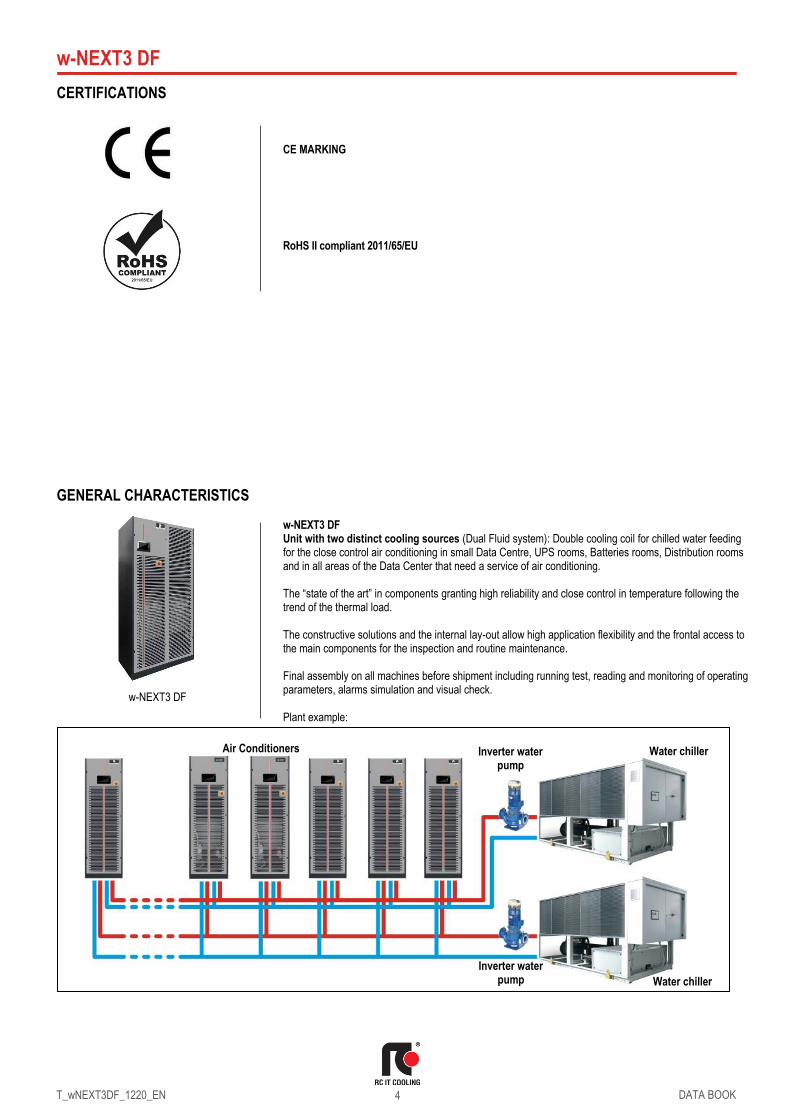
GENERAL CHARACTERISTICS w-NEXT3 DF Unit with two distinct cooling sources (Dual Fluid system): Double cooling coil for chilled water feeding for the close control air conditioning in small Data Centre, UPS rooms, Batteries rooms, Distribution rooms and in all areas of the Data Center that need a service of air conditioning. The “state of the art” in components granting high reliability and close control in temperature following the trend of the thermal load. The constructive solutions and the internal lay-out allow high application flexibility and the frontal access to the main components for the inspection and routine maintenance. Final assembly on all machines before shipment including running test, reading and monitoring of operating parameters, alarms simulation and visual check. Plant example:
w-NEXT3 DF
Air Conditioners Water chiller
Water chiller
Inverter water pump
Inverter water pump

w-NEXT3 DF
T_wNEXT3DF_1220_EN
DATA BOOK
5
The extreme flexibility allows top installation that adapts perfectly to every requirement of the plant with 2 types of air delivery: DOWNFLOW AIR DELIVERY (U - UNDER) Application suitable for server racks with vented front and rear doors. Typical installation is on the perimeter. the units are placed along the walls of the room. The air distribution is from the bottom by means of the plenum between the building floor and the raised floor. This solution is usually applied in hi-tech. air conditioning and it is most favourable when load is uniformly distributed in all areas of the room. The air distribution is achieved by special tiles placed in front of the racks row, forming cold aisle for air diffusion. On the rear of the racks is expelled the hot air then aspirated by the unit. For an optimal installation is advisable to provide the cold aisle containment. UPFLOW AIR DELIVERY (O - OVER) Application suitable for server racks with vented front and rear doors. Typical installation is on the perimeter. the units are placed along the walls of the room. The air distribution is from the top of the unit directly into the room by a plenum (or duct). The supply air flow can be directed through the adjustable fins of the plenum grilles. The system is normally applied in systems where it is not possible to provide a raised floor.

w-NEXT3 DF
T_wNEXT3DF_1220_EN
DATA BOOK
6
THE SERIES The units has been designed for a quick and easy setting up. The installation requires only electrical and hydraulic connections. A set of accessories allows to control the room temperature even in heating by electric heaters and, if necessary, also the humidity control by a modulating steam humidifier.
PRODUCT FEATURES AND BENEFITS
• Dual Fluid system with two distinct cooling sources.
• Improvement of the control software with advanced logic.
• Fast and easy installation.
• Plug fans with EC electric motors and impeller in aluminium or composite material, which guarantees a reduction of power consumption.
• New maintenance-free electric motor of the fan.
• Variable air flow according to the load.
• Cooling density up to 30.8 kW per m2 of occupied space.
• Totally removable panelling to facilitate extraordinary maintenance operations.
• Total front access for routine maintenance operations.
MODEL IDENTIFICATION
w-NEXT3 DF O 016 F2 <H>
w-NEXT3 Series DF Dual Fluid system
O Air delivery
O = over – upflow air delivery U = under – downflow air delivery DL = displacement – front air delivery
016 Model / Cooling capacity (kW) at nominal conditions
F2 Cabinet size <H> RoHS II compliant (Directive 2011/65/UE)
STORING TEMPERATURE If the machine is not installed on receipt and is stored for a long time, store it in a protected place, at temperatures ranging between -30°C and 46°C in absence of superficial condensation and direct sun light.
Model 009 Size F1
OVER UNDER
Model 016 Size F2
Air flow: 2200 m3/h Nominal cooling capacity: 7.90 kW
Air flow: 2200 m3/h Nominal cooling capacity: 7.90 kW
Air flow: 4300 m3/h Nominal cooling capacity: 15.4 kW
Air flow: 4300 m3/h Nominal cooling capacity: 15.4 kW

w-NEXT3 DF
T_wNEXT3DF_1220_EN
DATA BOOK
7
WORKING LIMITS
ROOM AIR CONDITIONS Room air temperature: 14°C minimum temperature with wet bulb. 27°C maximum temperature with wet bulb. 18°C minimum temperature with dry bulb. 45°C maximum temperature with dry bulb. AREA “A” Standard machine operating envelope. AREA “B” Machine operation envelope where the use of the hydrophilic coil is recommended
(optional “B821 Hydrophilic treatment”) Room air humidity: 20%RH minimum relative humidity. 60%RH maximum relative humidity. CHILLED WATER TEMPERATURE 6°C Minimum chilled water inlet temperature. 27°C Maximum chilled water inlet temperature. ΔT 3°C Minimum temperature difference between chilled water inlet and outlet. ΔT 10°C Maximum temperature difference between chilled water inlet and outlet.
HYDRAULIC CIRCUIT ΔP 5-150kPa Pressure drop range of the hydraulic circuit. 10 Bar Maximum working pressure of the hydraulic circuit. POWER SUPPLY ± 10% Maximum tolerance of the nominal supply voltage (V). ± 2% Maximum unbalancing of the phases.
LIMIT OF CHILLED WATER TEMPERATURE AT THE UNIT’S INLET
The table shows the recommended minimum water temperature at the unit’s inlet (°C), at different ambient air conditions. Lower chilled water temperatures may cause water droplets in the air flow or condensate drain problem.
Room Air Temperature
18°C 25°C 30°C 35°C 40°C 45°C
Rel
ativ
e H
um
idity
60% 6,0 10,4 16,4 -- -- --
50% 6,0 8,2 13,9 19,5 -- --
40% 6,0 6,0 11,2 16,5 -- --
30% 6,0 6,0 7,0 12,1 16,2 --
25% -- 6,0 6,0 8,9 13,2 --
20% -- 6,0 6,0 6,0 9,7 13,8
A
Rel
ativ
e h
um
idit
y -
%
Dry bulb temperature - °C
B

w-NEXT3 DF
T_wNEXT3DF_1220_EN
DATA BOOK
8
MAIN COMPONENTS FRAMEWORK
• Base and frame in galvanized steel, painted with epoxy powders. Colour RAL 7016.The inner frame is provided with seals for the panels.
• Panels in galvanized steel sheet with protective surfaces treatment in compliance with UNI ISO 9227/ASTMB117 and ISO 7253, and painted with epoxy powders. Colour RAL 7016 hammered.
• Panels insulated with polyurethane foam based on polyester polyol with melted protective film and seals to ensure airtight. Fire resistance HF1 – UL94.
• Hinged front panels with key fasteners and removable lateral and back side panels.
• Total front routine maintenance.
• Compartment for electrical panel on unit front for direct access to control and regulation devices.
• UNDER air flow: Air intake from the top and air delivery from the bottom.
• OVER air flow: Air intake from the front through honeycomb type grille and air delivery from the top with protection guard grille.
AIR FILTERS SECTION
• Washable air filters with COARSE 60% efficiency (according to ISO EN 16890) with cells in synthetic fibre and metallic frame.
• Air filters access on unit front.
COOLING SECTION
• Heat exchanger coil with internally corrugated copper tubes and high efficiency aluminium fins, specifically developed to provide high heat transfer and lower pressure drops; two separate circuits - main cooling circuit and Dual Fluid circuit.
• Condensate tray in stainless steel with PVC flexible discharge pipe.
• 2-way motorized valve for water flow regulation of the main cooling circuit with 0÷10 VDC control actuator and emergency manual control.
• 2-way motorized valve for water flow regulation of the Dual Fluid circuit with 0÷10 VDC control actuator and emergency manual control.
• Temperature probe on chilled water inlet of the main cooling circuit.
• Temperature probe on chilled water inlet of the Dual Fluid circuit.
• ISO 228G/1 chilled water inlet/outlet connection of main circuit and Dual Fluid circuit.
TEMPERATURE SENSOR ON AIR INTAKE / DELIVERY
• Temperature sensor on air intake with function of temperature display.
• Temperature sensor on air delivery with function of control and regulation.
FAN SECTION
• Centrifugal fans with backward curved blades with wing profile, single suction and without scroll housings (Plug-fans), directly coupled to external rotor electric motor.
• Impeller in aluminium or in composite material exempt from rust formation.
• Brushless type synchronous EC motor with integrated electronic commutated system.
• Fans speed control with proportional signal 0-10V.
• Fan protection guard grille on discharge side for Over version.
• Available external static pressure from 20 Pa up to max, adjustable with air flow rate.
ELECTRICAL PANEL In accordance with EN60204-1 norms, suitable for indoor installation, complete with:
• Main switch with door lock safety on front panel.
• Thermal-magnetic circuit breaker for supply fan.
• Transformer for auxiliary circuit and microprocessor supply.
• Numbered electric cables.
• Terminals for remote enabling, General Alarm signal and machine status.
• Power supply: 230/1/50. SAFETY DEVICES
• Automatic system to disconnect the power supply to fan in case of fire or smoke alarm (detectors suppled as optional).

w-NEXT3 DF
T_wNEXT3DF_1220_EN
DATA BOOK
9
CONTROL SYSTEM Microprocessor control system with graphic display for control and monitor of operating and alarms status. The system includes:
• Built-in clock for alarms date and time displaying and storing.
• Built-in memory for the storing of the intervened events (up to 200 events recorded).
• Hour-meter for main components.
• Non-volatile “Flash” memory for data storage in case of power supply faulty.
• Menu with protection password.
• LAN network for max. 15 units.
• Provision for connectivity cards housing.
OPTIONAL ACCESSORIES The descriptions of these additional components can be found in Chapter OPTIONAL ACCESSORIES.
B263 ..........................Bottom air intake + blind panels. Only for OVER version. The accessory foresees the blind frontal panels and allows the intake air from the bottom of the machine.
B264 ..........................Back air intake + blind panels. Only for OVER version. The accessory foresees the blind frontal panels and the intake air from the rear of the machine.
B821 ..........................Hydrophilic treatment of the cooling coil finned pack. A547 ..........................Constant flow: automatic system for the air flow control in the underfloor
(Under version), in the duct (Over version). The system controls the supply fans rotation speed to keep constant the air flow in the underfloor/duct via a differential pressure transmitter connected to the microprocessor control. Not compatible with constant prevalence control system.
A548 ..........................Constant prevalence: automatic system for the air pressure control in the underfloor (Under version), in the duct (Over version). The system controls the supply fans rotation speed to keep constant the air pressure in the underfloor/duct via a differential pressure transmitter connected to the microprocessor control. Not compatible with constant flow control system.
B792 ..........................Power supply 400/3+N/50 B794 ..........................Power supply 230/1/60 B795 ..........................Power supply 230/3/60 B796 ..........................Power supply 380/3+N/60 B798 ..........................Power supply 460/3+N/60 P091 ..........................Back-up module controller. The system guarantees the microprocessor power
supply for a few minutes, in case of supply voltage failure. Restriction: Not compatible with “Free-cooling plenum” and “Humidification”.
383 ............................Numbered wirings + UK requests. ..................................Serial cards: ..................................A471 - RS485 serial card. ..................................A472 - RS232 serial card. ..................................A473 – Ethernet card. ..................................A474 - LON card. B811 ..........................Air flow sensor. Air flow loss alarm with differential air pressure switch
connected to pressure probe on the fan suction mouth. A35B ......................... “Evolution touch” graphic display. A381 ..........................Drain pump. Supplied in mounting kit. A491 ..........................Water leakage detector: supplied in mounting kit. A492 ..........................Water leakage detector + additional sensor: supplied in mounting kit. A501 ..........................Clogged filters sensor with differential pressure switch on air side. A511 ..........................Smoke detector. Supplied in mounting kit. A521 ..........................Fire detector. Supplied in mounting kit. 5891 ..........................Unit control via Kiplink, A822 ..........................Adaptive set point: function that optimizes the operation of liquid chillers
connected to the indoor air conditioners by control of the effective room thermal load.
P141 ..........................Analogue set-point compensation. Analogue set point compensation according to an external analogue signal at Customer care.
A842 ..........................Network analyser. Multifunction utility for calculating and displaying the machine electrical measurements.
A812 (1) ....................Free-cooling direct control. A791 ..........................Air temperature control on suction air. B803 ..........................3-way 0-10V valve. 3-way motorized valve with 0÷10 VDC control actuator and
emergency manual control for the third way (by-pass) of the chilled water hydraulic circuit. The valve is in substitution of the main water flow control valve.
A431 ..........................Electric heater. Heating with electric heaters.

w-NEXT3 DF
T_wNEXT3DF_1220_EN
DATA BOOK
10
4301 (2) .....................Steam Humidifier: Modulating steam humidifier with immersed electrodes with electronic control, all with a metal cover on the top. The optional foresee the combined Temperature / Humidity sensor on return air and control board.
P051 (3) ....................Dehumidification function: The optional foresee the combined Temperature / Humidity sensor on return air.
P161 ..........................T/rH air intake sensor 4666 ..........................External air probe. P071 ..........................Remote T/rH probe. Combined Temperature / Humidity sensor for remote
installation. The optional is added to the standard temperature sensor on machine air intake.
P113 ..........................Dual power supply – External ATS: kit for double power supply with automatic change-over supplied in mounting kit.
P084 ..........................Air filter ePM10 50%: High efficiency air filter (according to ISO EN 16890). A532 ..........................Damper with spring return: non-return air damper driven by electric
servomotor installed on the top of units for all versions. The optional is not suitable for installation in seismic areas.
P011 ..........................Empty plenum. The optional is not suitable for installation in seismic areas. P012 ..........................Empty plenum CL. A1 (EN 13501-1). Plenum with fire reaction in class “A1”.
The optional is not suitable for installation in seismic areas. P013 ..........................Plenum + 3 grilles on three sides with double adjustable row. The optional is
not suitable for installation in seismic areas. P014 ..........................Plenum + 3 grilles CL. A1 (EN 13501-1). Plenum with grilles on three sides
with double adjustable row, with fire reaction in class “A1”. The optional is not suitable for installation in seismic areas.
P015 ..........................Silenced plenum. The optional is not suitable for installation in seismic areas. P016 ..........................Silenced plenum + 1 grille: Plenum with grille with double adjustable row on
front side and sound absorbers. The optional is not suitable for installation in seismic areas.
P031 ..........................Empty intake plenum. The optional is not suitable for installation in seismic areas.
P032 ..........................Empty intake plenum CL. A1 (EN 13501-1). Plenum with fire reaction in class “A1”. The optional is not suitable for installation in seismic areas.
P033 ..........................Silenced intake plenum. The optional is not suitable for installation in seismic areas.
P034 (4) ....................Intake free-cooling plenum for Under version. The optional foresee the combined Temperature / Humidity sensor on machine air suction, the Temperature sensor for ambient air and the expansion board for the microprocessor control. The optional is not suitable for installation in seismic areas.
P041 / P042 / P043 ...Support frame with height adjusting rubber holders. It is not possible to match the unit floor stand with plenum installed under the machine. The optional is not suitable for installation in seismic areas.
A272 ..........................CL. A1 (EN 13501-1) insulation: Panelling with fire reaction in class “A1. P151 ..........................Lowered display for Under: for units equipped with plenum under the unit. 9973 ..........................Wooden cage packing. The machines are delivered on pallet, covered with
shrink wrap and packaged in wooden cage. P101 ..........................Anti-seismic fixing kit, supplied in mounting kit. T500000310 ..............Additional condensate tray in peraluman for Under version size F1. T500000311 ..............Additional condensate tray in peraluman for Under version size F2. LM8300023 ...............Unit bind bracket to fix the unit to the wall size F1. LM8300054 ...............Unit bind bracket to fix the unit to the wall size F2. WARNING The Manufacturer reserves the right to accept the matching of the optional installed on the machine. MANDATORY COMBINATIONS OF ACCESSORIES 1. When optional accessory “A812 Free cooling direct control” is present, it requires mandatory
accessories “P161 T/rH air intake sensor“ and “4666 External air probe”. 2. When optional accessories “4301 Steam humidifier” are present, they require mandatory accessory
“P161 T/rH air intake sensor“. 3. When optional accessory “P051 Dehumidification function” is present, it requires mandatory
accessory “P161 T/rH air intake sensor“. 4. When optional accessory “P034 Intake free-cooling plenum” is present, it requires mandatory
accessories “P161 T/rH air intake sensor“, “4666 External air probe”, “A812 Free-cooling direct control”.

w-NEXT3 DF
T_wNEXT3DF_1220_EN
DATA BOOK
11
TECHNICAL DATA – UNDER / OVER version
MODEL 009 016
SIZE F1 F2
VERSION (1) U / O U / O
COOLING CAPACITY (2)
Total kW 7.90 15.4
Sensible kW 7.90 15.4
SHR (3) 1.0 1.0
"EC" SUPPLY FAN No. 1 2
Air flow m3/h 2200 4300
Nominal external static pressure Pa 20 20
Maximum external static pressure Pa 445 241
Power input (4) kW 0.24 0.47
COOLING COIL
Water flow rate (2) m3/h 1.36 2.65
dP coil + valve (2) kPa 61.1 46.5
Water content l 2.3 4.4
UNIT ELECTRIC DATA
Electric panel power input kW 0.015 0.015
SOUND LEVEL ISO 3744 (5)
Pressure level dB(A) 56 53
Power level dB(A) 72 69
AIR FILTERS No. 1 2
Extended filtering surface m2 0.68 1.05
Efficiency (ISO EN 16890) COARSE 60% 60%
ENERGY EFFICIENCY INDEX (2)
EER Energy Efficiency Ratio kW/kW 32.9 32.8
DIMENSIONS
Length mm 600 1000
Depth mm 500 500
Height mm 1980 1980
NET WEIGHT Over kg 116 177
NET WEIGHT Under kg 125 187
CONNECTIONS
Cooling coil inlet/outlet – ISO 228/1-G Ø 3/4” 1+1/4”
Condensate (6) Ø mm 19 19
Power supply wiring cable (7) No. x mm2 3G1.5 3G1.5
THE COOLING CAPACITY DOES NOT CONSIDER THE SUPPLY FAN MOTOR THERMAL LOAD
1. U = Under. downflow / O = Over. upflow. 2. Gross value. Characteristics referred to entering air at 26°C-40% RH; Chilled water
temperature 10-15°C – glycol solution 0%; ESP=20Pa. 3. SHR = Sensible cooling capacity / Total cooling capacity. 4. Corresponding to the nominal ESP=20Pa. 5. Sound pressure level on air return at 1m. 6. Rubber pipe – referred to internal diameter. 7. Minimum section of the power cable for units without accessories.

w-NEXT3 DF
T_wNEXT3DF_1220_EN
DATA BOOK
12
DUAL FLUID SYSTEM DUAL FLUID system on the machine allows to obtain two independent cooling systems:
The microprocessor control system automatically manages the system. by activating the cooling circuit more convenient according to the parameters set. With this system it is possible. with a limited use of space. to solve several plant problems such as:
• Chilled water coil fed with chilled water or mains water as a stand-by of the main cooling circuit.
• Double chilled water feeding with two independent circuit. This solution is used when you need to ensure redundancy of the cooling system.
The temperature control is performed with the same logic of the main coil. TECHNICAL DATA
VERSION (1) 009 016
MODEL F1 F2
SIZE U / O U / O
COOLING CAPACITY (2)
Total kW 7.90 15.4
Sensible kW 7.90 15.4
SHR (3) 1.0 1.0
DUAL FLUID COIL
Water flow rate (2) m3/h 1.36 2.65
dP coil + valve (2) kPa 61.1 46.5
Water volume l 2.3 4.4
HYDRAULIC CONNECTIONS
WATER INLET / OUTLET ISO 7/1 - R Ø 3/4” 1”
THE COOLING CAPACITY DOES NOT CONSIDER THE SUPPLY FAN MOTOR THERMAL LOAD 1. U = Under. downflow / O = Over. upflow 2. Gross value. Characteristics referred to entering air at 26°C-40%RH with chilled water
temperature 10-15°C - 0% glycol. ESP=20Pa. 3. SHR = Sensible cooling capacity / Total cooling capacity.
Air Conditioner Liquid chiller
Liquid chiller
Inverter water pump
Inverter water pump

w-NEXT3 DF
T_wNEXT3DF_1220_EN
DATA BOOK
13
1 unit in Stand-by
ACTIVE REDUNDANCY
Chilled water units, thanks to its electronically commutated EC fans, the 2-way motorized valves for chilled water flow control and an advanced algorithm to balance the heat loads among the units (including the units in stand-by), achieve an ACTIVE REDUNDANCY combining reliability, efficiency and reduced Total Cost of Ownership.
HYDRAULIC CIRCUIT
The diagrams refer to the standard configuration. without optional.
PASSIVE REDUNDANCY
ACTIVE REDUNDANCY
3 units ON @ 100%
4 units ON @ 75%
LEGENDA M1 2-vie modulating valve for main coil M4 2-vie modulating valve for Dual Fluid coil HE Main coil DF Dual Fluid coil.
Air flow
Water Inlet / Outlet Main circuit
Water Inlet / Outlet Dual Fluid circuit
OVER UNDER
Air flow
PF Plug Fan. T1 Air return temperature probe T2 Air supply temperature probe Tin Chilled water inlet temperature probe
Water Inlet / Outlet Main circuit
Water Inlet / Outlet Dual Fluid circuit

w-NEXT3 DF
T_wNEXT3DF_1220_EN
DATA BOOK
14
2-WAY BALL VALVE FOR CHILLED WATER FLOW CONTROL (main circuit and Dual Fluid circuit) The water flow control for each cooling circuit is acieved through a 2-way modulating ball valve with equal percentage flow control ensured by the integrated characterizing disc. This type of valve offers the following series of benefits:
• Equal percentage flow control.
• No peaks initial flow.
• Excellent stability control thanks to the integrated characterizing disc.
• Excellent characteristic in partialisation.
• Stability in control.
• Maintenance free.
• Self-cleaning. CHARACTERISTICS OF THE 2-WAY BALL VALVE
• Closing seal with leakage rate in Class A (EN 12266-1)
• Maximum fluid pressure Ps=1600kPa
• Maximum closing pressure (Close-off) ∆Ps=1400kPa The rotative actuator is controlled by a signal 0 … 10VDC from the microprocessor controller. The actuator is equipped with an emergency button for manual operation and is maintenance-free.
WATER QUALITY OF THE HYDRAULIC CIRCUITS The values shown in the table must be guaranteed during the entire life cycle of the machine.
Ref. Description Symbol Range
1 Hydrogen Ions pH 7.5 ÷ 9
2 Presence of calcium (Ca) and magnesium (Mg) Hardness 4 ÷ 8.5 °D
3 Chlorine ions Cl- < 150 ppm
4 Iron Ions Fe3+ < 0.5 ppm
5 Manganese Ions Mn2+ < 0.05 ppm
6 Carbon dioxide CO2 < 10 ppm
7 Hydrogen sulphide H2S < 50 ppb
8 Oxygen O2 < 0.1 ppm
9 Chlorine Cl2 < 0.5 ppm
10 Ammonia NH3 < 0.5 ppm
11 Ratio between carbonates and sulphates HCO3-/SO42- > 1
12 Sulphate ions SO4-- < 100 ppm
13 Phosphate ions PO43- < 2.0 ppm
where: 1/1.78°D = 1°Fr with 1°Fr = 10 gr CaCO3 / m3 ppm = parts for millions ppb = part for billion Explanatory notes: ref.1: A greater concentration of hydrogen ions (pH) than 9 implies a high risk of deposits. whereas
a lower pH than 7 implies a high risk of corrosion. ref.2: The hardness measures the amount of Ca and Mg carbonate dissolved in the water with a
temperature lower than 100°C (temporary hardness). A high hardness implies a high risk of deposits.
ref.3: The concentration of chloride ions with higher values than those indicated causes corrosion. ref. 4 - 5 - 8: The presence of iron and manganese ions and oxygen leads to corrosion. ref.6 - 7: Carbon dioxide and hydrogen sulphide are impurities that promote corrosion. ref.9: Usually in water from the waterworks it is a value of between 0.2 and 0.3 ppm. High values
cause corrosion. ref.10: The presence of ammonia reinforces the oxidising power of oxygen. ref.11: Below the value shown in the table. there is a risk of corrosion due to the trigger of galvanic
currents between copper and other less noble metals. ref.12: The presence of sulphates ions triggers corrosion phenomenon. ref.13: The presence of phosphates ions triggers corrosion phenomenon.

w-NEXT3 DF
T_wNEXT3DF_1220_EN
DATA BOOK
15
It is necessary to carry out periodic checks, with withdrawals at different points of the hydraulic system. During the first year of operation, checks are recommended every 4 months which can be reduced every 4 months starting from the second year of operation. WARNING: Values of the parameters outside the indicated ranges can lead to the formation of deposits and limescale and/or favour corrosive phenomena within the plant. For operating fluids other than water (mixtures of ethylene and propylene glycol) it is recommended to use specific inhibitors, designed to offer thermal stability within the operating temperature range and protection against corrosion. It is necessary that. in the presence of dirty and / or aggressive waters, an intermediate heat exchanger is installed upstream of the heat exchangers.
ANTIFREEZE MIXTURES In plants that are not adequately protected by heating cables, protect the hydraulic circuit with an anti-freeze mixture when the ambient air temperature can drop below 5°C.
Minimum ambient air temperature °C 5 0 -5 -10 -15 -20 -25 -30
ETHYLENE GLYCOL (suggested % in weight)
% 0 12 20 30 35 40 45 50
Minimum ambient air temperature °C 5 2 -3 -9 -13 -17 -23 -29
PROPYLENE GLYCOL (suggested % in weight)
% 0 10 20 30 35 40 45 50
The values are indicative and may significantly vary depending on the glycol manufacturer. Refer to your glycol supplier for detail. The values consider a precautionary difference of 5°C between the minimum ambient air temperature and the freezing temperature of the mixture. In the hydraulic circuit do not send fluids other than water or mixtures with ethylene / propylene glycol. If other products are provided, in addition to mixtures of water and ethylene or propylene glycol, contact the Manufacturer to check the compatibility with the machine components.
ACOUSTIC DATA Acoustic data of the standard machines at full load working conditions. WARNING: In a room the noise produced by a sound source reaches the listener in two different ways:
• Directly.
• Reflected from the surrounding walls. floor. ceiling and furniture. With the same sound source. the noise produced in a room is greater than that produced outdoors. In fact. the sound pressure level generated by the source must be added to the one reflected from the room. Also the shape of the room affects the sound.
MODEL 009 016
SIZE F1 F2
VERSION (1) U / O U / O
SOUND LEVEL ISO EN 3744 (2)
On air delivery dB(A) 63.9 60.2 On air intake UNDER dB(A) 59.6 55.9 On front side OVER dB(A) 54.6 51.0 On front side UNDER dB(A) 49.9 46.3
1. U = Under. downflow / O = Over. upflow 2. Sound Pressure level at 1 meter in free field – ISO EN 3744

w-NEXT3 DF
T_wNEXT3DF_1220_EN
DATA BOOK
16
ELECTRICAL DATA Electrical data of the unit at full load working conditions.
230/1/50-60 POWER SUPPLY
MODEL 009 016
SIZE F1 F2
VERSION (1) U / O U / O
Power supply V/Ph/Hz 230/1/50-60 230/1/50-60
Starting current (SA) A 4.0 7.2 MAX ABSORBED CURRENT (FLA)
Only cooling A 4.0 7.2 Cooling + Heating A 15.3 24.1
Cooling + Humidifier A 18.1 21.3
Cooling + Heating + Humidifier A 29.4 38.2
400/3+N/50 POWER SUPPLY
MODEL 009 016
SIZE F1 F2
VERSION (1) U / O U / O
Power supply V/Ph/Hz 400/3+N/50 400/3+N/50
Starting current (SA) A 4.0 7.2 MAX ABSORBED CURRENT (FLA)
Only cooling A 4.0 7.2 Cooling + Heating A 11.3 16.9
Cooling + Humidifier A 14.1 14.1
Cooling + Heating + Humidifier A 14.1 16.9
230/3/60 POWER SUPPLY
MODEL 009 016
SIZE F1 F2
VERSION (1) U / O U / O
Power supply V/Ph/Hz 230/3/60 230/3/60
Starting current (SA) A 4.0 7.2 MAX ABSORBED CURRENT (FLA)
Only cooling A 4.0 7.2 Cooling + Heating A 11.3 16.9
Cooling + Humidifier A 14.1 14.1
Cooling + Heating + Humidifier A 14.1 16.9
380/3+N/60 POWER SUPPLY
MODEL 009 016
SIZE F1 F2
VERSION (1) U / O U / O
Power supply V/Ph/Hz 380/3+N/60 380/3+N/60
Starting current (SA) A 4.0 7.2 MAX ABSORBED CURRENT (FLA)
Only cooling A 4.0 7.2 Cooling + Heating A 10.8 16.2
Cooling + Humidifier A 14.6 14.6
Cooling + Heating + Humidifier A 14.6 16.2
460/3+N/60 POWER SUPPLY
MODEL 009 016
SIZE F1 F2
VERSION (1) U / O U / O
Power supply V/Ph/Hz 460/3+N/60 460/3+N/60
Starting current (SA) A 4.0 7.2 MAX ABSORBED CURRENT (FLA)
Only cooling A 4.0 7.2 Cooling + Humidifier A 8.04 11.2
1. U = Under. downflow / O = Over. upflow

w-NEXT3 DF
T_wNEXT3DF_1220_EN
DATA BOOK
17
MICROPROCESSOR CONTROL SYSTEM
The indoor unit is equipped with the controller connected to a 6 keys keyboard with graphic display on which all information in English language or easily identifiable symbols are displayed. The controller disposes of a “flash” memory that preserves the information even in absence of power supply. Part of memory is dedicated to the registration of intervened events - up to 200 events. The system can manage up to 4 T/H probes on air intake, 4 T/H probes on air delivery, 4 remote T/H probes and a T/H probe for outdoor air.
DISPLAY - KEYBOARD FUNCTIONS
DISPLAY - MAIN MASK The main mask shows time. Date, room temperature and humidity values (if the relative probe is present) and areas for displaying operating and alarm status with dedicated icons: Area 1: Status of the unit: on / off Area 2: Status detail Area 3: Type of event (only in case of an event) Area 3_A: Code and type of event Area 4: Active cooling devices Area 5: Active free-cooling devices Area 6: Active humidity devices Area 7: Active heating devices Area 8: on / off parameters Area 9: BMS address Area 10: LAN address Area 11: Schematic representation of units CONNECTIVITY Using serial cards supplied as an accessory, the microprocessor control of the machine allows communication with modern remote management systems for buildings and plants with the following protocols: MODBUS. LON. BACNET MS / TP RS485. BACNET OVER IP.
ALARM Alarm presence with red light. Push for alarm description. In case of more alarms scroll by UP / DOWN.
PRG Menu list scrolled by UP/DOWN: Unit; Set-point; In/Out; Clock; History; User; Service; Factory. ENTER to execute.
ESC
Home. Used to come back to the previous menu level or to the main screen.
UP
DOWN
Changes pages and values of sets. By pressing in HOME mask, the synoptic of the main controls is displayed.
ENTER Moving the cursor on adjustable Program(s) fields to confirm the changes. Press ENTER to get out the fields.
Controller
Keyboard and Display
7” Touch Graphic Display (optional)

w-NEXT3 DF
T_wNEXT3DF_1220_EN
DATA BOOK
18
SYSTEM DIAGRAM
LAN NETWORK The LAN is part of the control software and it is possible to connect up to 15 units. This type of connection allows to control the units in coherent way, moreover the units can be controlled and managed from a shared remote terminal.
LAN ADDRESS LIST
Units n. 1 2 3 4 5 6 7 8 9 10 11 12 13 14 15 Remote terminal
Controller address 1 2 3 4 5 6 7 8 9 10 11 12 13 14 15 ---
Display & Keyboard address 16 17 18 19 20 21 22 23 24 25 26 27 28 29 30 32
The unit connection to the local network (LAN) allows to perform the following functions:
• Balancing the operating hours among the different units by rotating the reserve units.
• Turning on the reserve units in case other units should turn off due to an alarm, maintenance or power feed interruption.
• Turning on reserve units to offset the excessive thermal load.
• Operating with all units based on the average temperature and humidity values read by the temperature probes only in the operating units.
• DYNAMIC MASTER function that makes the role of the Master unit dynamic. In case of alarm, shutdown, maintenance, power failure, etc. on the Master unit, the function automatically elects a new Master unit.
Diagram in maximum configuration
Fan 1
Fan 2
Controller backup module
Network analyser
Expansion Board 3
Expansion Board 2
Expansion Board 1
Humidifier control
UNIT 1
Display Touch Controller
Additional Probe T/H
Probe T/H
Probe T
UNIT 2 UNIT 15 REMOTE TERMINAL
KIPLink
FieldBus2
BMS 2
LAN
BMS 1
RS485 Ethernet LON RS232

w-NEXT3 DF
T_wNEXT3DF_1220_EN
DATA BOOK
19
OPTIONAL ACCESSORIES: P122 - BOTTOM AIR INTAKE+BLIND PANELS Not available for Under (U) units. Thanks to the design of the basement is possible the air suction from the unit bottom. The air flow rate is the nominal one. The accessory foresees the blind frontal panels.
OPTIONAL ACCESSORIES: B264 – BACK AIR INTAKE+BLIND PANELS
Not available for Under (U) units. The accessory foresees the air intake from the unit back side and the blind frontal panels. The rear air intake opening is sized for the total air flow. The realization of the rear opening is at Customer care.
OVER VERSION F1 Backside view
OVER VERSION F2 Backside view

w-NEXT3 DF
T_wNEXT3DF_1220_EN
DATA BOOK
20
OPTIONAL ACCESSORIES: B821 – COOLING COIL HYDROPHILIC TREATMENT Finned pack with hydrophilic treatment that assure the condensate water drop. high thermal conductivity and does not favour the growth of micro-organisms.
OPTIONAL ACCESSORIES: A547 / A548 - CONSTANT FLOW / CONSTANT PREVALENCE
The optional is a differential pressure sensor with a 0…20mA output signal. The device is installed in the machine. The sensor is connected to the microprocessor control of the indoor unit and allows the control of:
A547 - CONSTANT FLOW The system controls the air flow of the air conditioner by measuring the static pressure before the inlet nozzle of the fan with the static pressure in the inlet ring. Pressure control range from 0 to 1000 Pa. The air flow control system is not compatible with constant prevalence control system. A458 - CONSTANT PREVALENCE The system controls the air pressure in the raised floor (Under version) or in the duct (Over version). Through the relief piping of the room pressure (low pressure side) and the air supply of the fan (high pressure side) the fan rotation speed is controlled to keep the air pressure constant. Pressure control range from 0 to 100 Pa. The air pressure control system is not compatible with constant flow control system.
OPTIONAL ACCESSORIES: B792 – 400/3+N/50 POWER SUPPLY OPTIONAL ACCESSORIES: B794 – 230/1/60 POWER SUPPLY OPTIONAL ACCESSORIES: B795 – 230/3/60 POWER SUPPLY OPTIONAL ACCESSORIES: B796 – 380/3+N/60 POWER SUPPLY OPTIONAL ACCESSORIES: B798 – 460/3+N/60 POWER SUPPLY OPTIONAL ACCESSORIES: P091 – BACKUP MODULE CONTROLLER
The optional is installed within the electrical panel. The optional accessory is not compatible with “Plenum for free-cooling” and with “Steam humidifier” optional accessories. The system guarantees the microprocessor power supply for a few minutes in case of supply voltage failure.

w-NEXT3 DF
T_wNEXT3DF_1220_EN
DATA BOOK
21
OPTIONAL ACCESSORIES: 383 – NUMBERED WIRINGS + UK REQUESTS The machine's electrical cables are all numbered for easy identification. For the power section it is possible to change the colour for the UK market.
CABLE 383 – COLOUR FOR UK
EARTH YELLOW / GREEN
NEUTRAL BLUE SKY
PHASE 1 (L1) BROWN
PHASE 2 (L2) BLACK
PHASE 3 (L3) GREY
AUXILIARIES RED
OPTIONAL ACCESSORIES: A471 – SERIAL CARD RS485
The card is factory installed. Consult the Interface Manual for all technical information.
OPTIONAL ACCESSORIES: A472 – SERIAL CARD RS232
The card is factory installed. Consult the Interface Manual for all technical information.
OPTIONAL ACCESSORIES: A473 – ETHERNET CARD
The card is factory installed. Consult the Interface Manual for all technical information.
OPTIONAL ACCESSORIES: A474 – SERIAL CARD LON
The card is factory installed. The manufacturer will supply the serial card and .NXE file and a .XIF files necessary for LonWorks technicians to configure the network. The board is programmed by the technician in charge of the integration. Consult the Interface Manual for all technical information.
OPTIONAL ACCESSORIES: B811 - AIR FLOW LOSS ALARM
The system includes a differential pressure switch installed in the electrical panel or in the front compartment of the indoor unit and the plastic hoses for the relief of the pressure in fan mouth. Control range: 0.2 … 2.0 mbar (20 … 200 Pa) Differential for intervention: 0.1 mbar (10 Pa) Supplied with the sensor set at fixed point of 0.2mbar. no availability to change it.

w-NEXT3 DF
T_wNEXT3DF_1220_EN
DATA BOOK
22
OPTIONAL ACCESSORIES: A35B – GRAPHIC DISPLAY “Evolution Touch” The optional is factory installed. 7” touch-screen graphic display with 16.7 million colors for the management and monitoring of operating and alarm status. The Display is equipped with a MicroUSB 2.0 port for the service connection. The navigation bars are always present on the display to allow quick and intuitive navigation.
TOP NAVIGATION BAR
1. Status of connection with the controller. Green: connection OK; Red: connection Error 2. Time and date 3. External temperature value by dedicated probe 4. Active percentage of Cooling 5. Active percentage of Heating 6. Active percentage of Post-Heating 7. Unit active functions 8. Power meter readings 9. PGD1 keyboard emulator 10. Rapid access to the menu (Quick menu)
BOTTOM NAVIGATION BAR
11. Light bar for machine status identification 12. Alarm button to access the alarm management screen and the number of active alarms 13. Home button for returning to the Homepage 14. pLAN network 15. Temperature of outlet air or percentage of humidity. 16. Operating mode button. 17. Inlet air temperature 18. Unit status 19. On/Off button
DISPLAY AREA
20. Main menu a. Operating mode and Set-Point b. Circuits c. Charts d. Compressors
For complete information on Graphic Display system, please consult the relative technical documentation.

w-NEXT3 DF
T_wNEXT3DF_1220_EN
DATA BOOK
23
OPTIONAL ACCESSORIES: A381 - DRAIN PUMP Not available for 380/3+N/60 and 460/3+N/60 power supply. The device in supplied in mounting kit. A plastic case contains the vertical type pump, the water tank with float plus safety switch and hydraulic and electric connection. Together the pump 10 linear meters anti-crushing plastic discharge spiral tube is supplied The optional must be installed as shown in the documentation delivered together with the unit. Wiring includes power supply and an alarm, displayed on microprocessor, that includes motor pump thermal protection and tank overflow. The condensate discharge pump operation is fully automatic. WARNING For all the machines the optional accessory is supplied in mounting kit. TECHNICAL DATA Power supply: 230V~ 50Hz Electrical data: 70W – 0,67A Maximum water flow: 500 l/h Maximum delivery height: 5.0 m Sound level: 45dBA a 1 m Maximum water temperature: 70°C Water acidity: pH>2.5 Tray volume: 2.0 l Protection IP 20 Dimensions: 279 x 130 x 171h (mm)
Total length of discharge pipes
(Ø 10 mm internal)
Discharge head
5m 10m 20m 30m
1m 380 300 240 190
2m 310 260 200 150
3m 240 200 145 110
4m 150 130 80 60
5m 30 20 0 0
(Dimensions in millimetres)

w-NEXT3 DF
T_wNEXT3DF_1220_EN
DATA BOOK
24
OPTIONAL ACCESSORIES: A491 - WATER LEAKAGE DETECTOR
The system includes an electronic relay installed in the electrical panel of the indoor machine. The electrical connections for the probe and the alarm contact are present in the indoor machine's terminal board. Sensor is installed inside unit for Over/Displacement air flow version and supplied to be connected and installed at customer care for Under air flow units.
OPTIONAL ACCESSORIES: A492 – WATER LEAKAGE DETECTOR + ADDITIONAL SENSOR
The system includes an electronic relay installed in the electrical panel of the indoor machine and 2 water detectors to be connected in series. The electrical connections for the probe and the alarm contact are present in the indoor machine's terminal board. The first sensor is installed inside unit for Over/displacement air flow version. In Under air flow version are supplied to be connected and installed at customer care.
OPTIONAL ACCESSORIES: A501 - CLOGGED FILTERS
The system includes a differential pressure switch installed in the electrical panel or in the front compartment of the indoor unit and the plastic hoses for the relief of the pressure upstream and downstream the air filters. Control range: 0.3 … 4.0 mbar (30 … 400 Pa) Differential for intervention: 0.15 mbar (15 Pa)
OPTIONAL ACCESSORIES: A511 – SMOKE DETECTOR
SMOKE DETECTOR The device in supplied in mounting kit. The optical smoke detector senses the presence of combustion by-products (visible smoke) and activates an alarm. The operating principle is based on the light scattering technique (Tyndall effect). The device is in conformity to EN 54-7 standard. Technical features:
Supplied as optional with unit to be connected and installed at customer care close to the unit.
Material ABS Relative humidity <93% not-condensing
Power supply 12...28 Vdc Index of protection IP 20
Normal current 50μA 24 Vdc Testing by magnet Yes
Alarm current 25mA 24 Vdc Relay max. 1A 30Vdc
LED visibility 360° (double led) Signal repeater 14mA 24 Vdc
Storage temperature -10…+70°C Covered area 40m2 max.
Operating temperature -10…+70°C Shielded connection cable
Min. 0.5 mm2
Max. speed air 0.2 m/s Colour White

w-NEXT3 DF
T_wNEXT3DF_1220_EN
DATA BOOK
25
OPTIONAL ACCESSORIES: A521 – FIRE DETECTOR FIRE DETECTOR The device in supplied in mounting kit. The fire detector has been designed to identify temperatures at which fires may start. When the temperature exceeds the set threshold or when there is a rapid variation in temperature, the relay is activated to signal an alarm. The device is in conformity to EN 54-5 standard. Technical features:
Supplied as optional with unit to be connected and installed at customer care close to the unit.
OPTIONAL ACCESSORIES: 5891 – CONTROL UNIT VIA KIPLINK The optional is factory installed. KIPlink is an innovative system based on Wi-Fi technology that allows to operate on a unit directly from Smartphone or Tablet via an APP.
WI-FI MODULE:
• Standard: IEEE 802.11n – 802.11g
• Frequencies: 2.4 – 2.4835 GHz
• Output power: <20 dBm (equivalent to <100mW)
• Safety: WPA2
• Flow: < 20m MEHITS APP
• Operating System: Android 5® or higher. IOS 8® or higher. Windows 10® or higher
• Download: Google Play®. Apple Store® e Microsoft Store®. HOW TO USE KIPLINK KIPlink can be used in two ways: Proximity keyboard: Approaching the machine with a Smartphone or a Tablet with the MEHITS APP
installed, you can connect to the machine via Wi-Fi and you can control it like the standard controller keyboard. It is possible to switch off / on the machine, change sets and reset alarms. Knowing the relative passwords, you access the parameters of the USER. SERVICE and MANUFACTURER menus.
Local Monitoring: Using a Smartphone, a Tablet or PC connected to the LAN of the building where
the machine is also connected. Access is via WEB via a browser. The system has two access profiles: ONLY READ and READ & WRITE.
ONLY READ allows only the visualization of the parameters and it is not possible to control the unit.
READ & WRITE allows you to switch off / on the machine, change sets and reset alarms. Knowing the relative passwords. you access the parameters of the USER. SERVICE and MANUFACTURER menus.
DATA STORE The system can store some data on a 1GB MicroSD card to be installed on the device. The data can be used for Service diagnostics. The card is not provided. KIPLINK NETWORK It is possible to set up mixed networks consisting of several KIPLink devices (10 maximum), to display information from different devices (called Client KIPLink) on one single device (called Master KIPLink). The information is collected from the various Client KIPLink devices connected to EVOLUTION+ / W3000 TE/ CX-4 controllers and sent through the Wi-Fi or Ethernet network to the Master KIPLink device, which stores them and makes them available through an appropriate user interface. The connection with the Master KIPlink can take place via Wi-Fi, via Ethernet or a combination of the two. For complete information on the KIPlink system, please consult the relative technical documentation.
Material ABS Index of protection IP 20
Power supply 12...28 Vdc Testing by magnet Yes
Normal current 50μA 24 Vdc Relay max. 1A 30Vdc
Alarm current 25mA 24 Vdc Signal repeater 14mA - 24 Vdc
LED visibility 360° (double LED) Alarm temperature threshold
62°C
Storage temperature -10…+70°C Covered area 40m2 max.
Operating temperature -10…+70°C Shielded connection cable
Min. 0.5 mm2
Relative humidity <93% non-condensing Colour White
Master
Client 1 Client 2 Client 3 Client 4
Logos, Trademarks and Company Name, are property of the respective Owners.

w-NEXT3 DF
T_wNEXT3DF_1220_EN
DATA BOOK
26
OPTIONAL ACCESSORIES: A822 – ADAPTIVE SET-POINT
ADAPTIVE SET-POINT An advanced algorithm that instantaneously detects the real thermal load of the indoor units and then conveys this information to the outdoor chillers, strongly increasing their operation.
• Dynamic variation of the chillers set point and water flow.
• Increasing of the free cooling mode.
• Adoption of the active redundancy system to better exploit stand-by chillers.
OPTIONAL ACCESSORIES: P141 – ANALOGUE SET-POINT COMPENSATION
Analogue set point compensation according to an external analogue signal at Customer care. The microprocessor control, through the additional module “expansion card”, can manage a compensation signal of the return air setpoint by analogue input (0...1V; 0...5V; 0.5...4.5V; 4...20mA; 0...20mA). The compensation curve allows to assign a temperature setpoint offset respectively to the minimum and maximum signal managed by the input.
OPTIONAL ACCESSORIES: A842 - NETWORK ANALYZER The optional is supplied in kit for external installation to the machine and includes:
• Main switch with door lock safety.
• Fuse.
• Network transducer.
• Current transformers. one for each power supply phase cable.
• Terminals. This device provides continuous measurement of power consumption. monitoring current, voltage and power. These values are sent to unit microprocessor via RS485 serial cable, as shown on the unit wiring diagram. The displayed variables are:
• Phase to phase voltage. only for three-phase units.
• Phase voltage (phase-neutral).
• Phase current.
• Neutral current only for three-phase units.
• Active phase power. only for three-phase units.
• Total active power.
• Active energy.
• Hour counts. Wall-mounting fixing screws not supplied Weight of the system: 5 kg Electrical connections at Customer care
OPTIONAL ACCESSORIES: A812 – FREE-COOLING DIRECT CONTROL
Not available for Over (O) version. Preparation of the machine and the electrical panel for the direct free-cooling system "P034 Intake free-cooling plenum".
OPTIONAL ACCESSORIES: A791 – AIR TEMPERATURE CONTROL ON AIR RETURN
Preparation of the machine for the control of the ambient air temperature with probes on air intake.
Dimensions in millimetres

w-NEXT3 DF
T_wNEXT3DF_1220_EN
DATA BOOK
27
OPTIONAL ACCESSORIES: A663 – 0-10V 3-WAY VALVE
Optional accessory of the cooling coil; The valve replaces the 2-way valve. 3-way modulating motorized valve with 0÷10 VDC control actuator and emergency manual control. The optional accessory is factory installed and do not modify the overall dimensions of the unit. This type of valve offers the following series of benefits:
• Equal percentage flow control.
• No peaks initial flow.
• Excellent stability control thanks to the integrated characterizing disc.
• Excellent characteristic in partialisation.
• Stability in control.
• Maintenance free.
• Self-cleaning. CHARACTERISTICS OF THE 3-WAY BALL VALVE
• Control path leakage rate A, air bubble-tight (EN 12266-1), bypass leakage rate I (EN 1349 e EN 60534-4).
• Maximum fluid pressure Ps=1600kPa.
• Maximum closing pressure (Close-off) ∆Ps=1400kPa.
• Maximum differential pressure ΔPmax=200 kPa. The rotary actuator is controlled by a 0 ... 10 VDC signal and is optimized for this type of valve. The valve opens by turning counterclockwise and closes by turning clockwise. The actuator is equipped with a button for manual emergency operation and is maintenance-free.
VERSION (1) U / O U / O
MODEL 009 016
SIZE F1 F2
3-VIE VALVE
kv – Flow coefficient m3/h 2.5 6.3
1. U = Under. downflow / O = Over. upflow
IMPORTANT For further information. please refer to chapter “VALVE PRESSURE DROP CALCULATION AS FUNCTION OF WATER FLOW RATE”.
UNDER OVER
Air flow
Air flow
LEGENDA M1 3-vie modulating valve – main circuit M1 3-vie modulating valve – Dual Fluid circuit HE Main coil DF Dual Fluid coil
Water Inlet / Outlet Dual Fluid circuit
PF Plug Fan T1 Air return temperature probe T2 Air supply temperature probe Tin Chilled water inlet temperature probe
Water Inlet / Outlet Main circuit
Water Inlet / Outlet Dual Fluid circuit
Water Inlet / Outlet
Main circuit

w-NEXT3 DF
T_wNEXT3DF_1220_EN
DATA BOOK
28
OPTIONAL ACCESSORIES: A431 - ELECTRIC HEATERS
Not available for 460/3+N/60 power supply. Electric heater consisting of finned aluminum elements, ensuring low surface temperature and deleting the air ionization problems. The optional is installed downstream the main cooling coil. In electric heaters with three working steps the activation is binary type. Components:
• Electric heater in aluminium armoured elements with integral fins.
• Electrical control.
• Safety thermostat.
230/1/50-60 POWER SUPPLY
SIZE F1 F2
VERSION (1) U / O U / O
THERMAL CAPACITY kW 2.6 3.9
Power supply V/Ph/Hz 230/1/50-60 230/1/50-60
Max absorbed current (FLA) A 11.3 16.9
First working step kW 1.3 1.3
Second working step kW 1.3 2.6
Third working step kW --- 1.3 + 2.6
NET WEIGHT (2) kg 5 10
400/3+N/50 POWER SUPPLY
SIZE F1 F2
VERSION (1) U / O U / O
THERMAL CAPACITY kW 2.6 3.9
Power supply V/Ph/Hz 400/3+N/50 400/3+N/50
Max absorbed current (FLA) A 11.3 16.9
First working step kW 1.3 1.3
Second working step kW 1.3 2.6
Third working step kW --- 1.3 + 2.6
NET WEIGHT (2) kg 5 10
230/3/60 POWER SUPPLY
SIZE F1 F2
VERSION (1) U / O U / O
THERMAL CAPACITY kW 2.6 3.9
Power supply V/Ph/Hz 230/3/60 230/3/60
Max absorbed current (FLA) A 11.3 16.9
First working step kW 1.3 1.3
Second working step kW 1.3 2.6
Third working step kW --- 1.3 + 2.6
NET WEIGHT (2) kg 5 10
380/3+N/60 POWER SUPPLY
SIZE F1 F2
VERSION (1) U / O U / O
THERMAL CAPACITY kW 2.4 3.6
Power supply V/Ph/Hz 380/3+N/60 380/3+N/60
Max absorbed current (FLA) A 10.8 16.2
First working step kW 1.2 1.2
Second working step kW 1.2 2.4
Third working step kW --- 1.2 + 2.4
NET WEIGHT (2) kg 5 10
1. U = Under. downflow / O = Over. upflow. 2. Value to be added to the weight of the standard unit.

w-NEXT3 DF
T_wNEXT3DF_1220_EN
DATA BOOK
29
OPTIONAL ACCESSORIES: 4301 – STEAM HUMIDIFIER
Modulating steam humidifier with immersed electrodes fitted with safety and running accessories. A metallic cover on the top and tank ensure the highest levels of safety during operation. Standard for safety flammability UL94: V0. The optional includes the combined temperature / humidity sensor on unit air intake and control board. The accessory is factory installed and requires only water filling connection. Humidifier water charge and discharge pipes are not supplied. It is recommended to install a filter and a shut-off valve on water inlet pipe. This humidifier produces non-pressurized steam by electrodes immersed in the water inside the cylinder: they bring the electric phase in the water that works as an electrical resistance and overheats. The steam so produced is distributed with dedicated distributors and used for ambient humidification or for industrial processes.
CHARACTERISTICS OF THE SUPPLY WATER The quality of the used water influences the evaporation process so the humidifier can be fed with not-treated water. only when potable and non-demineralised.
LIMIT VALUES
Min Max
Hydrogen ions pH 7 8.5
Specific conductivity at 20°C σR. 20 °C μS/cm 350 750
Total dissolved solids TDS mg/l (1) (1)
Dry residue at 180°C R180 mg/l (1) (1)
Total hardness TH mg/l CaCO3 100 (2) 400
Temporary hardness mg/l CaCO3 60 (3) 300
Iron + Manganese mg/l Fe + Mn 0 0.2
Chlorides ppm Cl 0 30
Silica mg/l SiO2 0 20
Residual chlorine mg/l Cl- 0 0.2
Calcium sulphate mg/l CaSO4 0 100
Metallic impurities mg/l 0 0
Solvents. diluents. soaps. lubricants mg/l 0 0
(1) Values depending on specific conductivity; in general: TDS ≅ 0.93 * σR. 20 °C; R180 ≅ 0.65 * σR (2) Not lower than 200% of the chloride content in mg/l di Cl- (3) Not lower than 300% of the chloride content in mg/l di Cl- WARNING:
• Use only with drinking water.
• There is no reliable relationship between hardness and water conductivity.
• Do not treat water with softeners! This could cause corrosion of the electrodes or the formation of foam, leading to potential operating problems or failures.
• Do not add disinfectants or corrosion inhibiters to water, as these substances are potentially irritant.
• Is absolutely forbidden to use well water. industrial water or water drawn from cooling circuits; in general, avoid using potentially contaminated water, either from a chemical or bacteriological point of view.
SIZE F1 F2
VERSION (1) U / O U / O
STEAM PRODUCTION kg/h 3.0 3.0
Water content l 3.9 3.9
Max water supply pressure Bar 1÷8 1÷8
NET WEIGHT (2) kg 4 4
HYDRAULIC CONNECTIONS
WATER INLET - ISO 228/1 – G M Ø 3/4" 3/4"
1. U = Under. downflow / O = Over. upflow 2. Value to be added to the weight of the standard unit. Does not include the weight of the water
content.
Humidifier control board

w-NEXT3 DF
T_wNEXT3DF_1220_EN
DATA BOOK
30
HUMIDIFIER ELECTRIC DATA 230/1/50-60 POWER SUPPLY
SIZE F1 F2
VERSION (1) U / O U / O
Power supply V/Ph/Hz 230/1/50-60 230/1/50-60
Power input kW 2.3 2.3
Absorbed current (OA) A 10.0 10.0
Max absorbed current (FLA) A 14.1 14.1
400/3+N/50 POWER SUPPLY
SIZE F1 F2
VERSION (1) U / O U / O
Power supply V/Ph/Hz 400/3+N/50 400/3+N/50
Power input kW 2.3 2.3
Absorbed current (OA) A 10.0 10.0
Max absorbed current (FLA) A 14.1 14.1
230/3/60 POWER SUPPLY
SIZE F1 F2
VERSION (1) U / O U / O
Power supply V/Ph/Hz 230/3/60 230/3/60
Power input kW 2.3 2.3
Absorbed current (OA) A 10.0 10.0
Max absorbed current (FLA) A 14.1 14.1
380/3+N/60 POWER SUPPLY
SIZE F1 F2
VERSION (1) U / O U / O
Power supply V/Ph/Hz 380/3+N/60 380/3+N/60
Power input kW 2.3 2.3
Absorbed current (OA) A 10.4 10.4
Max absorbed current (FLA) A 14.6 14.6
460/3+N/60 POWER SUPPLY
SIZE F1 F2
VERSION (1) U / O U / O
Power supply V/Ph/Hz 460/3+N/60 460/3+N/60
Power input kW 2.3 2.3
Absorbed current (OA) A 2.9 2.9
Max absorbed current (FLA) A 4.0 4.0
1. U = Under. downflow / O = Over. upflow
OPTIONAL ACCESSORIES: P051 - DEHUMIDIFICATION The system is automatic and checks for any increase in ambient humidity. Components:
• Temperature / Humidity sensor on the air intake.
• Electronic control system of the dew point temperature for the combined intervention of cooling capacity and air flow.

w-NEXT3 DF
T_wNEXT3DF_1220_EN
DATA BOOK
31
OPTIONAL ACCESSORIES: P161 – T/rH AIR INTAKE SENSOR
The accessory replaces the temperature sensor installed on the air intake in the indoor unit. The sensor is supplied with following option:
• Steam humidifier installation.
• Dehumidification system.
• Displaying of the relative humidity room value.
OPTIONAL ACCESSORIES: 4666 – EXTERNAL AIR PROBE
The probe must be installed protected against atmospheric agent and allows the displaying of the external air temperature. The sensor is mandatorily required with following option:
• P034 Intake free-cooling plenum.
OPTIONAL ACCESSORIES: P071 – REMOTE T/RH PROBE
The accessory is added to the standard temperature sensor or to the temperature / humidity sensor (optional) on the machine air intake. For indoor installation in a specific point of the room to be conditioned.
OPTIONAL ACCESSORIES: P113 - DUAL POWER SUPPLY
The optional is supplied in mounting kit and contained in polycarbonate box. The motorised changeover automatically manage changeover between two power supply lines, or manually for emergency operations. These devices are suitable for low voltage systems with interruption of the supply to the load during transfer. The model supplied in the automatic version checks the source and switches over automatically, based on configurable parameters. OPEN TRANSITION TYPE TRANSFER SWITCH WITH A MINIMUM INTERRUPTION OF THE SUPPLY DURING TRANSFER.
To maintain the microprocessor powered and avoid its restarts is mandatory to foresee the installation of the “temporary microprocessor power supply” optional accessory. The system guarantees the microprocessor power supply for a few minutes in case of supply voltage failure.
The wall mounting kit includes a plastic enclosure with following dimensions: SINGLE-PHASE system – IP55
Wall-mounting fixing screws not supplied Weight of the system: 12 kg Electrical connections at Customer care
Dimensions in millimetres

w-NEXT3 DF
T_wNEXT3DF_1220_EN
DATA BOOK
32
THREE-PHASES system – IP54
Wall-mounting fixing screws not supplied Weight of the system: 12 kg Electrical connections at Customer care
OPTIONAL ACCESSORIES: P084 – ePM10 50% AIR FILTERS The ePM10 50% air filters (according to ISO EN 16890) replace the standard one. The filters generate a pressure drops higher than the standard ones. The filters are made of glass micro-fibre and are not regenerable.
MODEL 009 016
SIZE F1 F2
VERSION (1) U / O U / O
Additional pressure drops (2) Pa 19 53
Reference air flow m3/h 2200 4300
1. U = Under. downflow / O = Over. upflow 2. Additional pressure drops referred to nominal air flow with clean filter.
Dimensions in millimetres

w-NEXT3 DF
T_wNEXT3DF_1220_EN
DATA BOOK
33
OPTIONAL ACCESSORIES: A532 – DAMPER WITH SPRING RETURN
Accessory installed on unit air delivery (Over version) or return (Under version) and it can be matched to plenum. The optional is not suitable for installation in seismic areas. FRAMEWORK
• Frame in galvanized steel sheet with protective surfaces treatment in compliance with UNI ISO 9227/ASTMB117 and ISO 7253 and painted with epoxy powders. Colour RAL 9005.
• Opposed blade dampers in galvanized steel sheet.
• Actuator for damper control with spring return.
• Terminals for electric connection to the unit.
WORKING LOGIC The damper opens at supply fans activation to allow air flow. When the fans stop for failure or stop command. the damper closes, preventing air flow into the unit.
SIZE F1 F2
VERSION (1) U / O U / O
Weight (2) kg 9 12
1. U = Under. downflow / O = Over. upflow 2. Add this value to the total unit weight
A532 OVER A532 UNDER

w-NEXT3 DF
T_wNEXT3DF_1220_EN
DATA BOOK
34
OPTIONAL ACCESSORIES: P011 … P034 - SUPPLY / INTAKE AIR PLENUM The optional is supplied separately and the installation on the unit is at Customer care. The plenums have same technical characteristics of the indoor unit cabinet. It is possible to install only a single plenum to ensure stability to the unit. The optional are not suitable for installation in seismic areas. FRAMEWORK
• Frame in aluminium extrusion, painted with epoxy powders. Colour RAL 7016.
• Panels in galvanized steel sheet with protective surfaces treatment in compliance with UNI ISO 9227/ASTMB117 and ISO 7253 and painted with epoxy powders. Colour RAL 7016.
• Panels insulated with polyurethane foam and seals to ensure airtight.
• Panels fixed with screws.
• Removable panels.
• Set of fixing elements to fasten the plenum to the unit.
Type of plenum:
• Empty supply/intake plenum. Also available with fire reaction in class “A1” (EN 13501-1).
• Plenum with frontal and lateral grilles. Also available with fire reaction in class “A1” (EN 13501-1) or reaction to fire classification.
• Plenum with soundproof sections.
• Plenum with frontal grille and soundproof sections.
P011 / P012 – P031 / P032: EMPTY PLENUM The plenum is void and can be used to rise the air inlet/outlet. Remove the frontal panels for inspection. Also available with fire reaction in class “A1” (EN 13501-1). The optional is not suitable for installation in seismic areas.
1. U = Under. downflow / O = Over. upflow 2. Add this value to the total unit weight
SIZE F1 F2
VERSION (1) U / O U / O
Weight (2) kg 12 16
Weight CL. A1 (2) kg 22 29
Dimensions in millimetres
P011 / P012 OVER P031 / P032 UNDER

w-NEXT3 DF
T_wNEXT3DF_1220_EN
DATA BOOK
35
P013 / P014: PLENUM + 3 GRILLES The plenum must be installed on air delivery. The plenum allows the air distribution directly into the room. The plenum is supplied with air distribution grilles with double row adjustable fins on front and lateral side. Also available with fire reaction in class “A1” (EN 13501-1). The optional is not suitable for installation in seismic areas.
1. U = Under. downflow / O = Over. upflow 2. Add this value to the total unit weight
SIZE F1 F2
VERSION (1) U / O U / O
Weight (2) kg 12 16
Weight CL. A1 (2) kg 17 22.5
P013 / P014 OVER P013 / P014 UNDER
Dimensions in millimetres

w-NEXT3 DF
T_wNEXT3DF_1220_EN
DATA BOOK
36
P015: SILENCED PLENUM The plenum must be installed on air delivery. The plenum is fitted with sound absorbers to reduce the noise emission. Remove the frontal panels for inspection. The optional is not suitable for installation in seismic areas.
1. U = Under. downflow / O = Over. upflow 2. Add this value to the total unit weight
ACOUSTIC DATA
1. U = Under. downflow / O = Over. upflow / DL = Displacement air flow 2. Noise pressure level at 1 meter in free field – ISO 3744 3. Air intake from the front. 4. Nominal air flow with noise absorption partitions plenum installation and external static pressure
20 Pa.
SIZE F1 F2
VERSION (1) U / O U / O
Weight (2) kg 18 24
MODEL 009 016
SIZE F1 F2
VERSION (1) U / O U / O
SOUND LEVEL ISO EN 3744 (2)
On air delivery. Under (2) dB(A) 59.9 56.1
On air delivery. Over (3) dB(A) 59.9 56.1
Air flow (4) m3/h 2200 4300
Dimensions in millimetres
P015 OVER P015 UNDER

w-NEXT3 DF
T_wNEXT3DF_1220_EN
DATA BOOK
37
P033: SILENCED INTAKE PLENUM Not available for Over (O) version. The plenum is fitted with sound absorbers to reduce the noise emission. Remove the frontal panels for inspection. The optional is not suitable for installation in seismic areas.
1. U = Under. downflow 2. Add this value to the total unit weight
ACOUSTIC DATA
MODEL 009 016
SIZE F1 F2
VERSION (1) U U
SOUND LEVEL ISO 3744 (2)
On air intake. Under dB(A) 55.7 52
Air flow (3) m3/h 2200 4300
1. U = Under. downflow 2. Noise pressure level at 1 meter in free field – ISO 3744. 3. Nominal air flow with noise absorption partitions plenum installation and external static pressure
20 Pa.
SIZE F1 F2
VERSION (1) U U
Weight (2) kg 18 24
P033 UNDER
Dimensions in millimetres

w-NEXT3 DF
T_wNEXT3DF_1220_EN
DATA BOOK
38
P016: SILENCED PLENUM + 1 GRILLE The plenum must be installed on air delivery. The plenum allows the frontal air distribution directly into the room and a noise reduction of the air delivery. The plenum is supplied with air distribution grille with double row adjustable grills on front side and sound absorbers. The optional is not suitable for installation in seismic areas.
1. U = Under. downflow / O = Over. upflow 2. Add this value to the total unit weight
ACOUSTIC DATA
MODEL 009 016
SIZE F1 F2
VERSION (1) U / O U / O
SOUND LEVEL ISO 3744 (2)
On air delivery. Under dB(A) 58.5 54.9
On air delivery. Over dB(A) 58.5 54.9
Air flow m3/h 2200 4300
1. U = Under. downflow / O = Over. upflow 2. Noise pressure level at 1 meter in free field – ISO 3744
SIZE F1 F2
VERSION (1) U / O U / O
Weight (2) kg 12 16
P016 OVER P016 UNDER
Dimensions in millimetres

w-NEXT3 DF
T_wNEXT3DF_1220_EN
DATA BOOK
39
OPTIONAL ACCESSORIES: P034 – INTAKE FREE-COOLING PLENUM Not available for Over (O) version. The optional is supplied separately and the installation on the unit is at Customer care. The plenums have same technical characteristics and base dimensions of the machine cabinet. The optional allow to obtain free-cooling by direct ambient air intake into the room. The dampers are proportionally managed by the microprocessor control, that regulates the quantity of the ambient air to put in the room according to the set-point. The optional is not suitable for installation in seismic areas. COMPONENTS
• Frame in aluminium extrusion, painted with epoxy powders. Colour RAL 7016.
• Panels in galvanized steel sheet with protective surfaces treatment in compliance with UNI ISO 9227/ASTMB117 and ISO 7253 and painted with epoxy powders. Colour RAL 7016.
• Panels insulated with polyurethane foam and seals to ensure airtight.
• Removable panels fixed with screws.
• Opposed blade dampers in galvanized steel sheet and safety grille for ambient air and room air suction.
• Actuator for each damper.
• Terminals for electric connection to the unit.
• Set of fixing elements to fasten the plenum to the unit.
• Combined Temperature / Humidity sensor on machine air suction. The sensor must be moved outside the air conditioners for a proper read of the room temperature value.
• Temperature sensor for outdoor air. The sensor must be installed in the outdoor air suction duct or anyway protected against atmospherics agent.
• Expansion board for microprocessor control.
• Free contact for free-cooling operating status monitoring.
• Terminals on indoor unit for: o 24 Vac power supply for the overpressure damper servomotor. o 0-10Vdc control signal for the servomotor.
Servomotor and overpressure damper are not supplied. Ducting for ambient air suction are at Customer care. A rain cover with grille on ambient air intake is recommended.
Size F1 F2
VERSION (1) U U
Weight (2) kg 18 25
1. U = Under. downflow 2. Add this value to the total unit weight
Expansion board of the microprocessor control
Rain cover with grille (not supplied)
Duct (not supplied)
UNDER

w-NEXT3 DF
T_wNEXT3DF_1220_EN
DATA BOOK
40
AIR EXHAUSTION DAMPER – Not supplied
WARNING IT IS COMPULSORY TO INSTALL IN THE ROOM TO BE CONDITIONED A MOTORIZED DAMPER APPROPRIATELY DIMENSIONED FOR THE EXHAUSTION OF AIR FROM THE ROOM DURING FREE-COOLING OPERATION. During free-cooling operation, the air conditioner supplies ambient air directly into the room, this causes an increase in air pressure inside the room. The exhaustion damper avoids the increase in pressure in the room. The damper must be installed at the highest point of the room to exhaust excess hot air to the outside. Install the damper if possible. in opposite position to air conditioner. The damper is controlled by the modulating signal 0-10Vdc of the free-cooling control of the air conditioner. The 24Vac power supply of the servomotor and the 0-10Vdc free-cooling signal is available on the unit's electrical terminal block (see wiring diagram for connections). Air exhaustion must be protected with a rain cover and a grille (at Customer care). The electrical connection cables are not supplied.
DIMENSIONS OF THE EXHAUSTION DAMPER
MODEL 009 016
Damper area m2 0.2 0.4
Air flow m3/h 2200 4300
In case of several units installed in the same room that operate simultaneously. it is possible to install a single damper with adequate section.
Exhaustion damper with servomotor (not supplied)
Rain cover with grille (not supplied

w-NEXT3 DF
T_wNEXT3DF_1220_EN
DATA BOOK
41
OPTIONAL ACCESSORIES: P041 / P042 / P043 - SUPPORT FRAME
The optional is supplied in mounting kit. It is not possible to match the base frame with plenum installed under the machine. For a correct installation of the air conditioner we suggest you utilize a gasket between the base frame and the unit base. The base frame is available in 3 models with 3 different heights. The optional is not suitable for installation in seismic areas.
MODEL Hmax350 Hmax450 Hmax510
Code P041 P042 P043
H min. height mm 255 355 400
H max. height mm 350 450 510
1. U = Under. downflow / O = Over. upflow
OPTIONAL ACCESSORIES: A272 – CL.A1 (EN13501-1) INSULATION
The optional is designed TO SUPPLY THE PANELING ONLY WITH FIRE REACTION IN CLASS A1 (EN 13501-1)”; furthermore. allows a noise insulation of the panels of the air conditioners. The pressure level reduction of the unit is about 2 dB(A). The reduction refers ONLY to the sound level radiated from the unit or in front of the unit. The noise level data on return and delivery air do not undergo reductions. The accessory includes:
• External part as standard panel.
• Internal part in galvanized steel sheet.
• The inside noise insulation with special soundproof material. REACTION TO FIRE CLASSIFICATION On Italian territory, the classification is per the D.M. of June 26. 1984 and subsequent amendments, providing for a sort in "Classes" from 0 (non-combustible material) to 5 (extremely flammable material). The EN 13501-1 regulation is ordered in classes from A1 (non-combustible material) to F (extremely flammable material). A comparison of the classes is not possible because the methods and evaluation criteria are completely different. The comparison table below is being considered purely indicative.
It is possible to provide the sandwich panels for the OVER units with air flow from the top. This implies that the air intake must necessarily be from the base of the unit with front blind panelling (optional “B263 Bottom air intake + blind panels”). The accessory increases the unit weight:
SIZE F1 F2
OVER Weight increasing (1) kg 26 35
UNDER Weight increasing (1) kg 31 42
1. Add this value to the total unit weight
Definition Italian classes EN 13501-1
Non-combustible material Class 0 A1
Combustible material. very limited contribution to fire Class 1 A2 – B
Combustible material. limited contribution to fire Class 2 A2 – B - C
Combustible material. medium contribution to fire Class 3 C – D
Combustible material. highly contribution to fire Class 4 E
Combustible material. easily flammable Class 5 F

w-NEXT3 DF
T_wNEXT3DF_1220_EN
DATA BOOK
42
OPTIONAL ACCESSORIES: P151 – LOWERED DISPLAY FOR UNDER For machines installed above the supply plenum. The display / keypad on the front panel of the machine is installed lowered by about 50cm to facilitate consultation and use.
OPTIONAL ACCESSORIES: P101 - ANTI-SEISMIC FIXING KIT
The optional is supplied in mounting kit. Two lateral supports that must be fixed at the machine basement sides. supplied with fixing bolts. This is a safety device that must be mounted before the unit installation and connected to a structural part with adequate resistance in the installation site to prevent the risk of unit movement or overturning due to earthquake. Fixing screws to the structural part not supplied.
The fixing of the unit to the structure is at Customer care. To grant anti-seismic resistance the unit must be fixed to a structural part with adequate resistance with 4 steel screws M10 (not supplied). Each anchoring system must resist to a lifting traction force as shown in table.
MODEL 009 016
SIZE F1 F2
VERSION (1) U / O U / O
Number of screws No. 4 4
Type of screw M10 M10
Traction resistance needed. single anchor. Under
kg 968 1471
Traction resistance needed. single anchor. Over
kg 1025 1595
1. U = Under. downflow / O = Over. upflow
Dimensions in millimetres

w-NEXT3 DF
T_wNEXT3DF_1220_EN
DATA BOOK
43
OPTIONAL ACCESSORIES: T500000310 / 311 - CONDENSATE TRAY (only UNDER version)
Additional condensing tray for Under flow version in peraluman. This component must be considered as a safety device to install in the floor under the unit in the event of water leaks. The water leakage sensor is supplied to be installed at customer care in the additional condensing tray. The tray is equipped with a water drainage system Ø 22mm.
Condensate tray with water leakage sensor
Dimensions in millimetres

w-NEXT3 DF
T_wNEXT3DF_1220_EN
DATA BOOK
44
OPTIONAL ACCESSORIES: LM8300023 / 54 - UNIT BIND BRACKET The bracket is supplied in mounting kit. This bracket is supplied complete with fixing bolts to the machine. This is a safety device that must be installed together with the unit and connected to a structural part in the installation site (wall, structure, etc.) to prevent the risk of unit overturning due to external causes (accidental impact, earthquake, etc.). Wall fixing screws not supplied.
Dimensions in millimetres

w-NEXT3 DF
T_wNEXT3DF_1220_EN
DATA BOOK
45
MACHINE DRAWINGS Dimensions in mm – UNDER F1

w-NEXT3 DF
T_wNEXT3DF_1220_EN
DATA BOOK
46
MACHINE DRAWINGS Dimensions in mm – UNDER F2

w-NEXT3 DF
T_wNEXT3DF_1220_EN
DATA BOOK
47
MACHINE DRAWINGS Dimensions in mm – OVER F1

w-NEXT3 DF
T_wNEXT3DF_1220_EN
DATA BOOK
48
MACHINE DRAWINGS Dimensions in mm – OVER F2

w-NEXT3 DF
T_wNEXT3DF_1220_EN
DATA BOOK
49
HOLE IN THE RAISED FLOOR FOR DOWNFLOW VERSION HOLE IN THE RAISED FLOOR WITHOUT SUPPORT FRAME
Foresee a hole in the floor with the following dimensions:
SIZE F1 F2
A mm 540 940
B mm 440 440
C mm 90 90
HOLE IN THE RAISED FLOOR WITH SUPPORT FRAME (OPTION) Foresee a hole in the floor with the following dimensions:
SIZE F1 F2
A mm 610 1010
B mm 510 510
C mm 60 60

w-NEXT3 DF
T_wNEXT3DF_1220_EN
DATA BOOK
50
EXAMPLE FOR MACHINES NOISE EMISSION CALCULATION
UNDER UNIT WITH DUCT ON AIR INTAKE
Duct Lp A = Front side Under catalogue value Lp B = Air delivery Under catalogue value Lp C = Air intake Under catalogue value The points B and C do not influence the point A
UNDER UNIT WITH PLENUM ON AIR DELIVERY
Lp A = Front side Under catalogue value Lp B = Air delivery Under catalogue value –plenum noise reduction Lp C = Air intake Under catalogue value
Lp A+C = 10 log10 (10 +10 ) The point B do not influence the point A
LpA 10
LpC 10
UNDER UNIT WITH PLENUM ON AIR INTAKE
Lp A = Front side Under catalogue value Lp B = Air delivery Under catalogue value Lp C = Air intake Under catalogue value – plenum noise reduction
Lp A+C = 10 log10 (10 +10 ) The point B do not influence the point A
LpA 10
LpC 10
OVER UNIT WITH DUCT
Lp A = Air intake Over catalogue value Lp B = Air delivery Over catalogue value The point B do not influence the point A

w-NEXT3 DF
T_wNEXT3DF_1220_EN
DATA BOOK
51
EXAMPLE FOR MACHINES NOISE EMISSION CALCULATION IMPORTANT The declared noise levels are intended in free field conditions. The noise pressure level of an installed unit is affected by the room acoustic characteristics. Please consider an average noise increase of +4/+6 dB(A).
OVER UNIT WITH PLENUM ON AIR DELIVERY
Lp A = Air intake Over catalogue value Lp B = Air delivery Over catalogue value – plenum noise reduction
Lp A+B = 10 log10 (10 +10 )
LpA 10
LpC 10
OVER UNIT WITH DUCT AND PLENUM ON AIR DELIVERY
Lp A = Radiated Over catalogue value Lp B = Air delivery Over catalogue value Lp C = Lp A + 6dB(A) – plenum noise reduction
Lp A+C = 10 log10 (10 +10 ) The point B do not influence the point A+C
LpA 10
LpC 10
OVER UNIT WITH DUCT AND PLENUM ON AIR DELIVERY
Lp A = Radiated Over catalogue value Lp B = Air delivery Over catalogue value Lp C = Lp D = Lp A + 6 dB(A) – plenum noise reduction The points B, C and D do not influence the point A
Blind front panel
Blind front panel

w-NEXT3 DF
T_wNEXT3DF_1220_EN
DATA BOOK
52
SHIPMENT: PACKING DIMENSIONS Values referred to basic machine. The presence of some accessories increases the weight of machine. The machines are shipped on pallet and covered with carton box. On request packing on pallet covered with shrink wrap and wooden cage. The optional “A532 Damper with spring return” is shipped mounted on the machine and increases its weight and height. The shipping weight of the machine includes the unit bind bracket, the water leakage detector and only for Under version the condensate tray.
UNDER / OVER Version UNDER / OVER Version
Model Size A
(mm) B
(mm) H
(mm) H1
(mm) Model Size
A (mm)
B (mm)
H (mm)
H1 (mm)
009 F1 750 650 2100 2220 009 F1 790 690 2250 2450
016 F2 1100 650 2100 2220 016 F2 1140 690 2250 2450
H1 = Machine with optional A532 Damper with spring return
SHIPMENT: SHIPPING WEIGHT
Version U (UNDER)
Model 009 016
Size F1 F2
PACKING TYPE
Standard kg 140 209
Standard (1) kg 149 221
Wooden cage kg 162 232
Wooden cage (1) kg 171 244
Version O (OVER)
Model 009 016
Size F1 F2
PACKING TYPE
Standard kg 135 203
Standard (1) kg 144 215
Wooden cage kg 157 226
Wooden cage (1) kg 166 238
(1) Machine with optional A532 Damper with spring return
STANDARD PACKING DIMENSIONS
OPTIONAL 9973: WOODEN CAGE PACKING DIMENSIONS

w-NEXT3 DF
T_wNEXT3DF_1220_EN
DATA BOOK
53
SHIPMENT: OPTIONALS PACKING DIMENSIONS AND SHIPPING WEIGHT
P041 / P042 / P043: SUPPORT FRAME The frames are shipped on pallet and covered with shrink wrap.
A842: NETWORK ANALYZER P113: DUAL POWER SUPPLY – External ATS The optional are shipped in carton box.
A842
NETWORK ANALYZER
P113 DUAL SUPPLY
Size F1 F2 F1 F2
DIMENSIONS
A mm 410 410 400 400
B mm 410 410 400 400
H mm 210 210 210 210
SHIPPING WEIGHT kg 5 5 12 12
P101: ANTISEISMIC FIXING KIT The kit is shipped togheter the machine.
Size F1 F2
Weight kg 2.3 2.3
Size F1 F2
DIMENSIONS
SHIPPING WEIGHT kg 29 31

w-NEXT3 DF
T_wNEXT3DF_1220_EN
DATA BOOK
54
P011 / P012 – P031 / P032: EMPTY PLENUM P013 / P014: PLENUM + 3 GRILLES P015: SILENCED PLENUM P033: SILENCED INTAKE PLENUM P016: SILENCED PLENUM + 1 GRILLE P034: INTAKE FREE COOLING PLENUM The plenums are shipped on pallet and covered with shrink wrap.
“O” Over / “U” Under
Size F1 F2
DIMENSIONS
A mm 750 1100
B mm 650 650
H mm 670 670
SHIPPING WEIGHT
P011 - Empty plenum “O” kg 23 31
P012 - Empty plenum CL. A1 (EN 13501-1) “O” kg 33 44
P031 - Empty plenum “U” kg 23 31
P032 - Empty plenum CL. A1 (EN 13501-1) “U” kg 33 44
P013 - Plenum + 3 grilles “O” / “U” kg 23 31
P014 - Plenum + 3 grilles CL. A1 (EN 13501-1) “O” / “U” kg 28 38
P015 - Silenced plenum “O” / “U” kg 29 39
P033 - Silenced intake plenum “U” kg 29 39
P016 - Silenced plenum + 1 grille + “O” / “U” kg 23 31
P034 - Intake free cooing plenum “U” kg 29 40

w-NEXT3 DF
T_wNEXT3DF_1220_EN
DATA BOOK
55
VALVE PRESSURE DROP CALCULATION AS FUNCTION OF WATER FLOW RATE Flow coefficient kv defines the water flow (between 5°C and 40°C) expressed in m3/h that cross a valve
with a pressure drop of 1bar (100kPa). With this data is possible to calculate the localized pressure drop as function of the water flow rate.
P = (Q / kv) 2
P (bar) = localized pressure drop of valve.
Q (m3/h) = water flow rate – it varies according to the desired operating condition. kv (m3/h) = valve flow coefficient.
The formula allows to calculate the value of the localized pressure drop (in bar). The pressure drops values showed on the documentation are supplied in kPa. Is possible to change from one unit to another through the following conversion. 1 bar = 100kPa
CALCULATION EXAMPLE OF 2-WAY VALVE PRESSURE DROP IN FUNCTION OF CHILLED WATER COIL WATER FLOW RATE Model 022 F2 – CHILLED WATER COIL Example at nominal conditions. Characteristics referred to entering air at 26°C-40%RH with chilled water temperature 10-15°C - 0% glycol. Water flow rate: 3.5 m3/h
Valve flow coefficient kv: 6.3 m3/h
2-way valve for by-pass pressure drop:
P = (Q / kv) 2 = (3.5 / 6.3) 2 = 0.309 (bar) * 100 (kPa / bar) = 30.9 kPa.

Via Caduti di Cefalonia, 1 - 36061 Bassano del Grappa (VI) Italy Ph. (+39) 0424 509 500 • Fax (+39) 0424 509 509
www.melcohit.com