vnr vignan jyothi instiyute of engineering … · vnr vignan jyothi instiyute of engineering and...
TRANSCRIPT
VNR VIGNAN JYOTHI INSTIYUTE OF ENGINEERING AND TECHNOLOGY
BACHUPALLY (VIA), KUKATPALLY, HYDERABAD-72
ACADEMIC PLAN: 2016-17
IV Year B. Tech EEE – I Sem ( B–Sec) L T/P/D C
3 1 3
Subject: Principles of Digital Signal Processing Subject Code: 13ECE083
Number of working days : 90
Number of Hours / week : 5
Total number of periods planned : 60
Name of the Faculty Member : Mr. P. Sai Kumar Naidu
PREREQUISITES
MTH1101, MTH1102, MTH1104, MTH1103, ECE1104, ECE1109
COURSE OBJECTIVES
1. Analyze discrete time systems using time domain concepts and frequency domain concepts of convolution,
difference equation and Z transform, frequency response respectively.
2. Define and Implement Discrete Fourier series and Discrete Fourier Transform (DFS & DFT).
3. Apply the Fast Fourier Transform (FFT) algorithms for efficient implementation of DFT and Linear
Convolution.
4. Design the simple Finite Impulse Response (FIR) and Infinite Impulse Response (IIR) filters and understand
the stability of them. (Classical design methods using analog filters).
5. Understand the Multi rate signal processing – Decimation and Interpolation and Applications.
6. Understand the Finite word length effects, quantization effects and noise on filter implementation.
COURSE OUTCOMES
Upon completion of this course, students should be able to:
1. Apply fundamental knowledge of mathematics to modeling and analysis of Signal processing problems
in Electronics and Instrumentation, Communication, Bio-medical engineering.
2. Design the different types of digital FIR and IIR filters, based on tailor made applications, as well as
documenting them in engineering reports.
3. Apply the Multi rate signal processing techniques and finite word length effects techniques in multi-
disciplinary engineering.
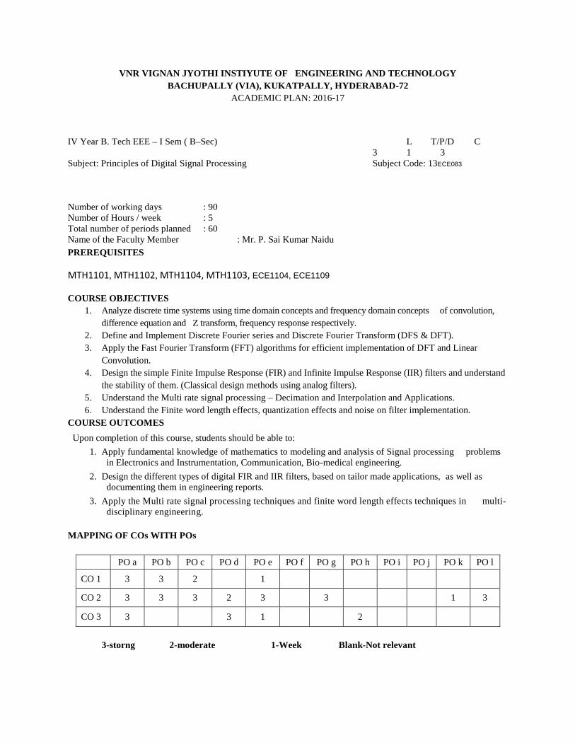
MAPPING OF COs WITH POs
PO a PO b PO c PO d PO e PO f PO g PO h PO i PO j PO k PO l
CO 1 3 3 2
1
CO 2 3 3 3 2 3
3
1 3
CO 3 3
3 1
2
3-storng 2-moderate 1-Week Blank-Not relevant
DETAILED SYLLABUS
UNIT- I
INTRODUCTION:
Classification of continuous time Signals & Systems, Linear shift invariant systems, stability and causality,
Sampling of Continuous signals- Introduction to digital signal processing-Sampling process-Sampling theorem.
Classification of discrete time signals and sequences
Learning Outcomes
After completion of this unit the student will be able to
1. Describe the distinctions between analog, continuous-time, discrete-time and digital signals, and describe
the basic operations involved in analog-digital(A/D) and digital-analog (D/A) conversion.
2. Define simple non-periodic discrete-time sequences such as the impulse and unit step, and perform time-
shifting and time-reversal operations on such sequences.
3. State the condition for a discrete-time sinusoid to be periodic.
4. Apply simple sequences (impulse, step, and sinusoid) to the input of such filters and hand-calculate the
filter output given either the system block diagram or the linear difference equation.
5. Given the difference equation of a discrete-time system, be able to apply tests (or examples and counter
examples) to demonstrate linearity, time invariance, causality and stability, and hence show whether or no
at given system belongs to the important class of causal, LTI (linear time-invariant)systems.
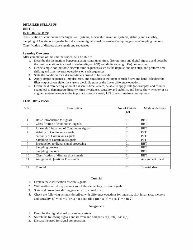
TEACHING PLAN
S. No Description No. of Periods
(12)
Mode of delivery
1 Basic Introduction to signals 01 BBT
2 Classification of continuous signals 01 BBT
3 Linear shift invariant of Continuous signals 01 BBT
4 stability of Continuous signals 01 PPT
5 causality of Continuous signals 01 PPT
6 Sampling of Continuous signals 01 PPT
7 Introduction to digital signal processing 01 BBT
8 Sampling process 01 BBT
9 Sampling theorem 01 BBT
10 Classification of discrete time signals 01 BBT
11 Assignment Questions Discussion 01 Assignment Sheet
12 Tutorial 01 Tutorial sheet
Tutorial
1. Explain the classification discrete signals.
2. With mathematical expressions sketch the elementary discrete signals.
3. State and prove time shifting property of z-transform.
4. Check the following systems described with difference equations for linearity, shift invariance, memory
and causality: (i) y (n) + y (n+1) = n x (n). (ii) y (n) = x (n) + x (n-1) + x (n-2).
Assignment
1. Describe the digital signal processing system
2. Sketch the following signals and its even and odd parts: x(n) =8(0.5)n u(n).
3. Discuss the need for signal compression.
UNIT-II
FOURIER ANALYSIS:
Introduction to Discrete Fourier series, Discrete Fourier Transform: Properties of Discrete Fourier Transform, linear
convolution and circular convolution of sequences using DFT, Computation of DFT, Relation between DFT and Z-
Transform. Fast Fourier transform: Radix -2 decimation in time and decimation in frequency FFT algorithms,
Inverse FFT.
Learning Outcomes
After completion of this unit the student will be able to
1. Compute the Discrete-time Fourier transform (DTFT) of a simple sequence such as the impulse response of
an FIR filter.
2. Derive and apply the time-shifting property of the DTFT
3. Explain the form of symmetry of the DTFT (magnitude & phase components) for real and complex time
sequences.
4. Derive the frequency-shifting property of the DTFT.
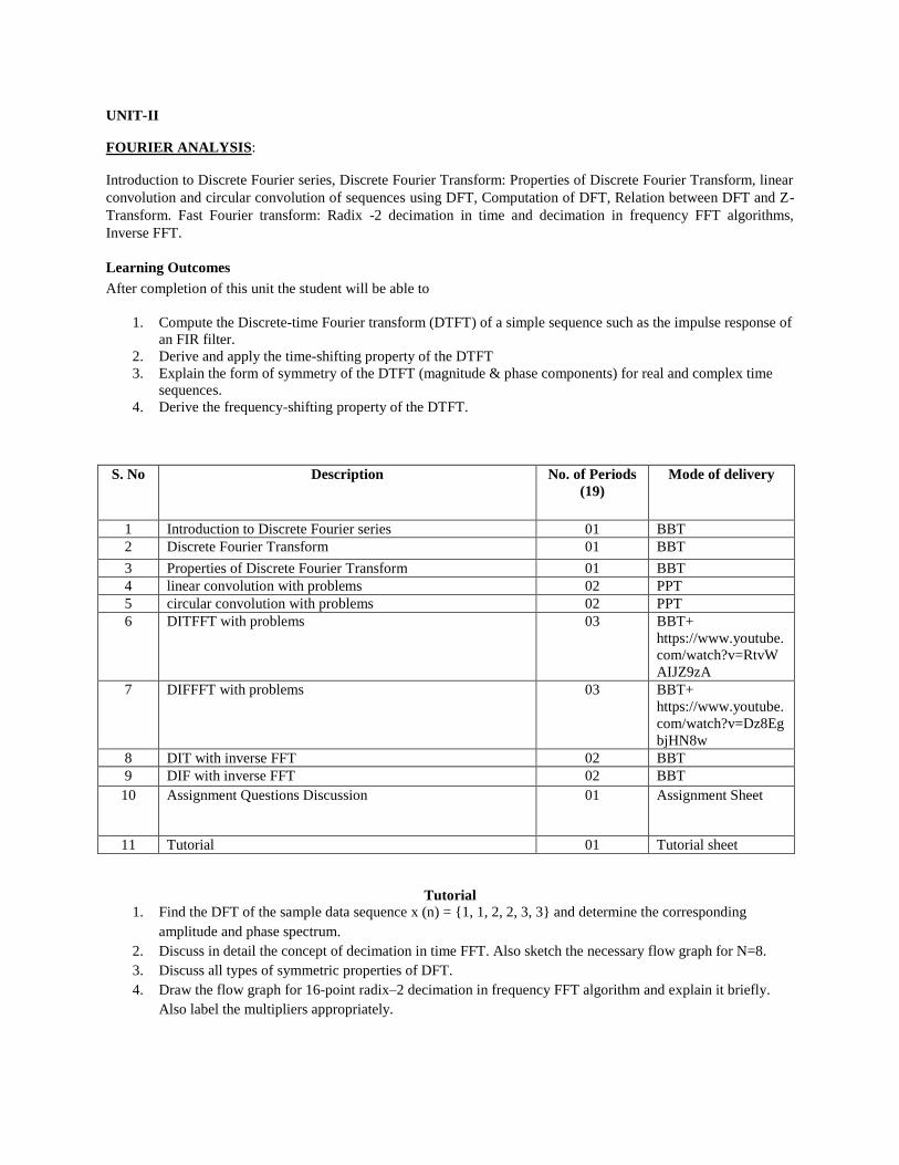
S. No Description No. of Periods
(19)
Mode of delivery
1 Introduction to Discrete Fourier series 01 BBT
2 Discrete Fourier Transform 01 BBT
3 Properties of Discrete Fourier Transform 01 BBT
4 linear convolution with problems 02 PPT
5 circular convolution with problems 02 PPT
6 DITFFT with problems 03 BBT+
https://www.youtube.
com/watch?v=RtvW
AIJZ9zA
7 DIFFFT with problems 03 BBT+
https://www.youtube.
com/watch?v=Dz8Eg
bjHN8w
8 DIT with inverse FFT 02 BBT
9 DIF with inverse FFT 02 BBT
10 Assignment Questions Discussion 01 Assignment Sheet
11 Tutorial 01 Tutorial sheet
Tutorial
1. Find the DFT of the sample data sequence x (n) = {1, 1, 2, 2, 3, 3} and determine the corresponding
amplitude and phase spectrum.
2. Discuss in detail the concept of decimation in time FFT. Also sketch the necessary flow graph for N=8.
3. Discuss all types of symmetric properties of DFT.
4. Draw the flow graph for 16-point radix–2 decimation in frequency FFT algorithm and explain it briefly.
Also label the multipliers appropriately.
Assignment
1. Given the two sequences of length ‘4’ as under x(n) = {1,2,3,1} h(n) = {4,3,2,2}. Verify the answer using
DFT method.
2. Compare DIT-FFT and DIF-FFT algorithms.
3. State and prove circular convolution property of DFT.
4. Find DFT of sequence using DIT – FFT, the sequence is x (n) = {1, 1, 1, 1, 1, 1, 1, 1}.
5. Compute the 4-point DFT of the sequence x (n) = (1, 0, 1, 0) using DIF-FFT radix – 2 algorithm. Compare
the answer with conventional approach.
UNIT-III
Z- TRANSFORM:
Introduction to Z-transform, Properties of Z- Transform, Inverse Z- Transform, Application of Z- Transforms for
Linear constant coefficient difference equations, Realization of Digital filters, system function – stability criterion.
Learning Outcomes
After completion of this unit the student will be able to
1. Calculate the z-transform X(z) of a simple sequence x(n) (such as exponentials and sinusoids): specify the
region of convergence (ROC) and the bounding poles of X(z).
2. Derive the time-shifting property of the z-transform
3. Given a z-transform X(z) and its ROC, state whether or not the DTFT of x(n) exists, and predict whether
the sequence x(n) is left-sided, right-sided, two-sided, and/or of finite duration.
4. Apply z-transform properties and theorems, notably convolution, time reversal, and multiplication by an
exponential sequence (plus time-shifting property listed earlier)
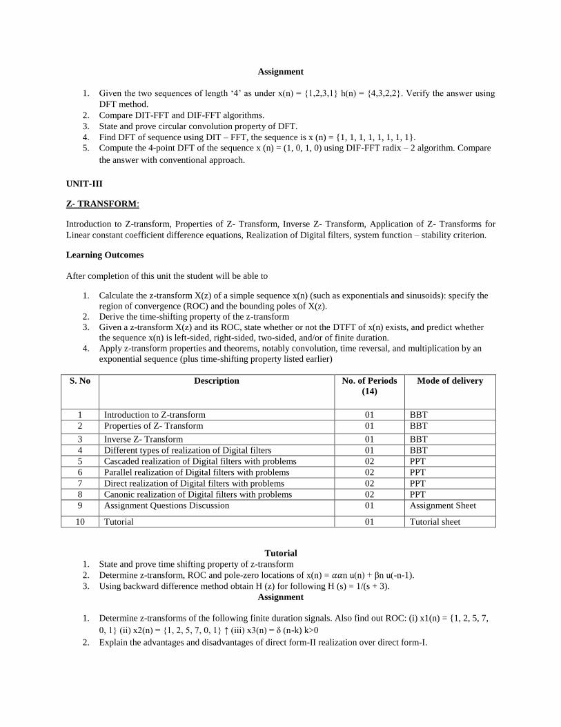
S. No Description No. of Periods
(14)
Mode of delivery
1 Introduction to Z-transform 01 BBT
2 Properties of Z- Transform 01 BBT
3 Inverse Z- Transform 01 BBT
4 Different types of realization of Digital filters 01 BBT
5 Cascaded realization of Digital filters with problems 02 PPT
6 Parallel realization of Digital filters with problems 02 PPT
7 Direct realization of Digital filters with problems 02 PPT
8 Canonic realization of Digital filters with problems 02 PPT
9 Assignment Questions Discussion 01 Assignment Sheet
10 Tutorial 01 Tutorial sheet
Tutorial
1. State and prove time shifting property of z-transform
2. Determine z-transform, ROC and pole-zero locations of x(n) = 𝛼𝛼n u(n) + βn u(-n-1).
3. Using backward difference method obtain H (z) for following H (s) = 1/(s + 3).
Assignment
1. Determine z-transforms of the following finite duration signals. Also find out ROC: (i) x1(n) = {1, 2, 5, 7,
0, 1} (ii) x2(n) = {1, 2, 5, 7, 0, 1} ↑ (iii) x3(n) = δ (n-k) k>0
2. Explain the advantages and disadvantages of direct form-II realization over direct form-I.
3. Realize following system with difference equation in cascade form: y(n) = (3/4) y(n-1) – (1/8) y(n-2) + x(n)
+ (1/3)x(n-1)
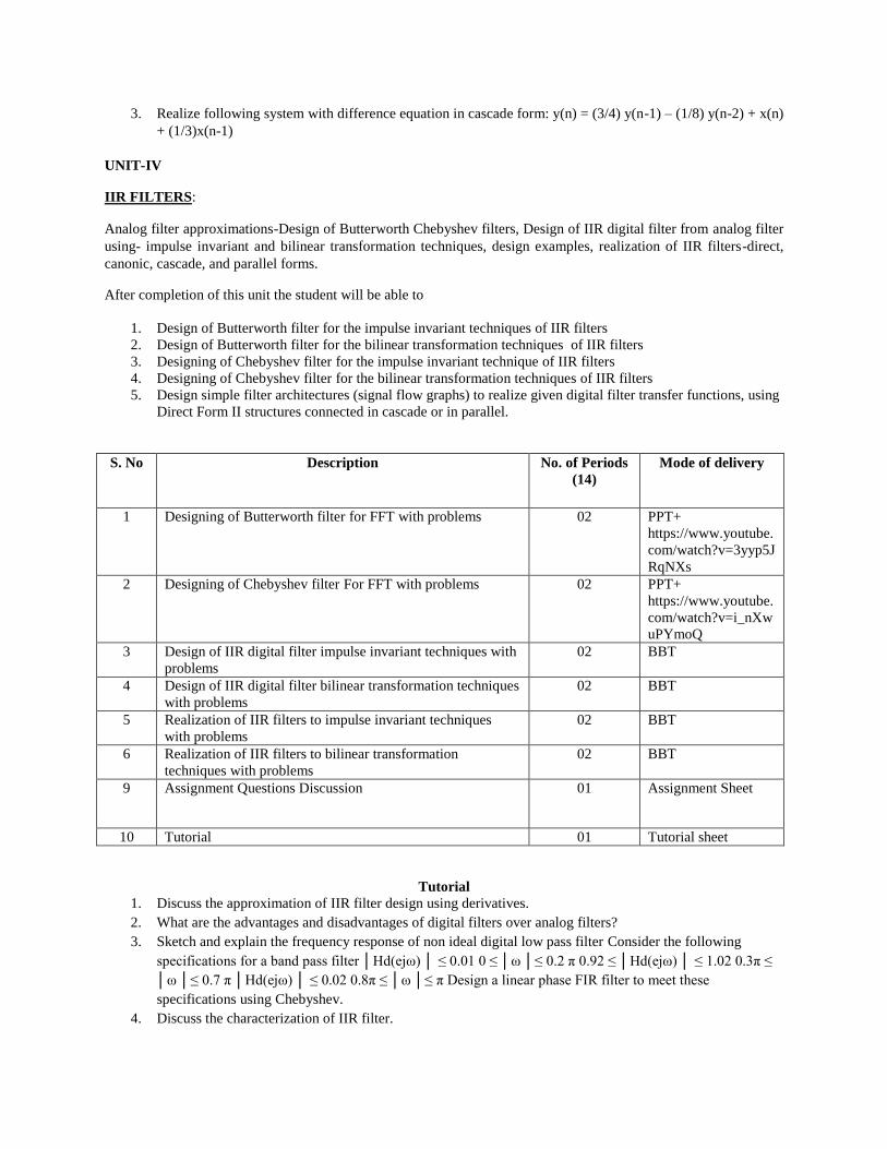
UNIT-IV
IIR FILTERS:
Analog filter approximations-Design of Butterworth Chebyshev filters, Design of IIR digital filter from analog filter
using- impulse invariant and bilinear transformation techniques, design examples, realization of IIR filters-direct,
canonic, cascade, and parallel forms.
After completion of this unit the student will be able to
1. Design of Butterworth filter for the impulse invariant techniques of IIR filters
2. Design of Butterworth filter for the bilinear transformation techniques of IIR filters
3. Designing of Chebyshev filter for the impulse invariant technique of IIR filters
4. Designing of Chebyshev filter for the bilinear transformation techniques of IIR filters
5. Design simple filter architectures (signal flow graphs) to realize given digital filter transfer functions, using
Direct Form II structures connected in cascade or in parallel.
S. No Description No. of Periods
(14)
Mode of delivery
1 Designing of Butterworth filter for FFT with problems 02 PPT+
https://www.youtube.
com/watch?v=3yyp5J
RqNXs
2 Designing of Chebyshev filter For FFT with problems 02 PPT+
https://www.youtube.
com/watch?v=i_nXw
uPYmoQ
3 Design of IIR digital filter impulse invariant techniques with
problems
02 BBT
4 Design of IIR digital filter bilinear transformation techniques
with problems
02 BBT
5 Realization of IIR filters to impulse invariant techniques
with problems
02 BBT
6 Realization of IIR filters to bilinear transformation
techniques with problems
02 BBT
9 Assignment Questions Discussion 01 Assignment Sheet
10 Tutorial 01 Tutorial sheet
Tutorial
1. Discuss the approximation of IIR filter design using derivatives.
2. What are the advantages and disadvantages of digital filters over analog filters?
3. Sketch and explain the frequency response of non ideal digital low pass filter Consider the following
specifications for a band pass filter │Hd(ejω) │ ≤ 0.01 0 ≤ │ω │≤ 0.2 π 0.92 ≤ │Hd(ejω) │ ≤ 1.02 0.3π ≤
│ω │≤ 0.7 π │Hd(ejω) │ ≤ 0.02 0.8π ≤ │ω │≤ π Design a linear phase FIR filter to meet these
specifications using Chebyshev.
4. Discuss the characterization of IIR filter.
Assignment
1. Describe Butterworth approximation of obtaining IIR filter transfer function for given frequency response.
2. Explain the features of Chebyshev approximation.
3. Discuss the location of poles for Chebyshev filter
4. Describe the IIR filter design approximation using Impulse Invariant method. Also sketch the s – plane to z
plane mapping. State its merits and demerits.
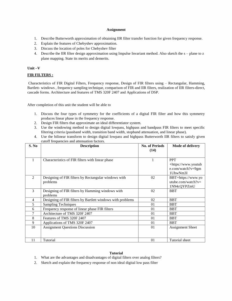
Unit –V
FIR FILTERS :
Characteristics of FIR Digital Filters, Frequency response, Design of FIR filters using – Rectangular, Hamming,
Bartlett- windows , frequency sampling technique, comparison of FIR and IIR filters, realization of IIR filters-direct,
cascade forms. Architecture and features of TMS 320F 2407 and Applications of DSP.
After completion of this unit the student will be able to
1. Discuss the four types of symmetry for the coefficients of a digital FIR filter and how this symmetry
produces linear phase in the frequency response.
2. Design FIR filters that approximate an ideal differentiator system.
3. Use the windowing method to design digital lowpass, highpass and bandpass FIR filters to meet specific
filtering criteria (passband width, transition band width, stopband attenuation, and linear phase).
4. Use the bilinear transform to design digital lowpass and highpass Butterworth IIR filters to satisfy given
cutoff frequencies and attenuation factors.
S. No Description No. of Periods
(14)
Mode of delivery
1 Characteristics of FIR filters with linear phase 1 PPT
+https://www.youtub
e.com/watch?v=9gm
1UhwNm3I
2 Designing of FIR filters by Rectangular windows with
problems
02 BBT+https://www.yo
utube.com/watch?v=
1N94cQYPZmU
3 Designing of FIR filters by Hamming windows with
problems
02 BBT
4 Designing of FIR filters by Bartlett windows with problems 02 BBT
5 Sampling Techniques 01 BBT
6 Frequency response of linear phase FIR filters 01 BBT
7 Architecture of TMS 320F 2407 01 BBT
8 Features of TMS 320F 2407 01 BBT
9 Applications of TMS 320F 2407 01 BBT
10 Assignment Questions Discussion 01 Assignment Sheet
11 Tutorial 01 Tutorial sheet
Tutorial
1. What are the advantages and disadvantages of digital filters over analog filters?
2. Sketch and explain the frequency response of non ideal digital low pass filter
3. Consider the following specifications for a band pass filter │Hd(ejω) │ ≤ 0.01 0 ≤ │ω │≤ 0.2 π 0.92 ≤
│Hd(ejω) │ ≤ 1.02 0.3π ≤ │ω │≤ 0.7 π │Hd(ejω) │ ≤ 0.02 0.8π ≤ │ω │≤ π Design a linear phase FIR
filter to meet these specifications using Bartlett window.
4. With the help of illustrations explain zero interpolation, step interpolation and linear interpolation.
Assignment
1. Explain the FIR filter design using windowing technique.
2. Compare FIR and IIR filters.
3. Discuss the realization of FIR filter structures.
4. Discuss about characteristics linear phase FIR filters.
5. What are the effects of windowing?
6. Consider the following specifications for a band pass filter: │Hd (ejω) │ ≤ 0.01 0 ≤ │ω │≤ 0.2π 0.92 ≤
│Hd (ejω) │ ≤ 1.02 0.3π ≤ │ω │≤ 0.7π │Hd (ejω) │ ≤ 0.02 0.8π ≤ │ω │≤ π Design a linear phase FIR
filter to meet these specifications using Hamming window.
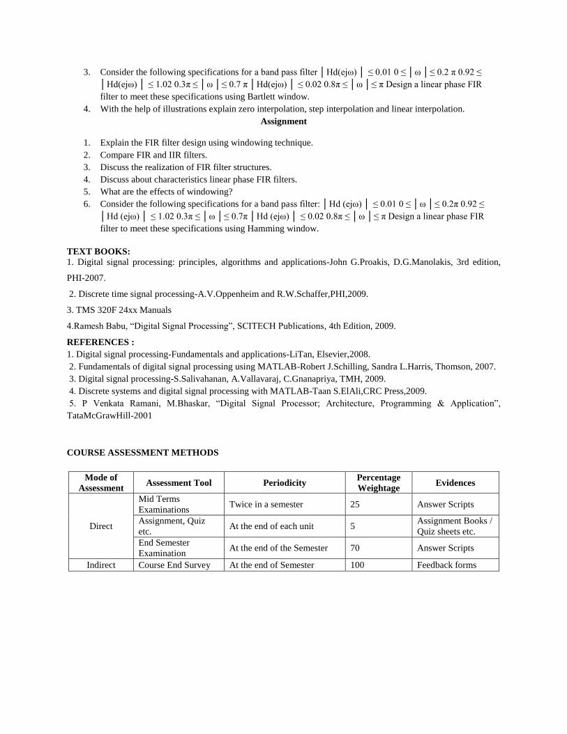
TEXT BOOKS:
1. Digital signal processing: principles, algorithms and applications-John G.Proakis, D.G.Manolakis, 3rd edition,
PHI-2007.
2. Discrete time signal processing-A.V.Oppenheim and R.W.Schaffer,PHI,2009.
3. TMS 320F 24xx Manuals
4.Ramesh Babu, “Digital Signal Processing”, SCITECH Publications, 4th Edition, 2009.
REFERENCES :
1. Digital signal processing-Fundamentals and applications-LiTan, Elsevier,2008.
2. Fundamentals of digital signal processing using MATLAB-Robert J.Schilling, Sandra L.Harris, Thomson, 2007.
3. Digital signal processing-S.Salivahanan, A.Vallavaraj, C.Gnanapriya, TMH, 2009.
4. Discrete systems and digital signal processing with MATLAB-Taan S.ElAli,CRC Press,2009.
5. P Venkata Ramani, M.Bhaskar, “Digital Signal Processor; Architecture, Programming & Application”,
TataMcGrawHill-2001
COURSE ASSESSMENT METHODS
Mode of
Assessment Assessment Tool Periodicity
Percentage
Weightage Evidences
Direct
Mid Terms
Examinations Twice in a semester 25 Answer Scripts
Assignment, Quiz
etc. At the end of each unit 5
Assignment Books /
Quiz sheets etc.
End Semester
Examination At the end of the Semester 70 Answer Scripts
Indirect Course End Survey At the end of Semester 100 Feedback forms
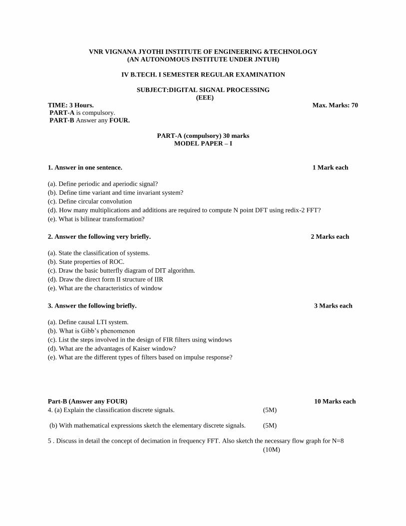
VNR VIGNANA JYOTHI INSTITUTE OF ENGINEERING &TECHNOLOGY
(AN AUTONOMOUS INSTITUTE UNDER JNTUH)
IV B.TECH. I SEMESTER REGULAR EXAMINATION
SUBJECT:DIGITAL SIGNAL PROCESSING
(EEE)
TIME: 3 Hours. Max. Marks: 70
PART-A is compulsory.
PART-B Answer any FOUR.
PART-A (compulsory) 30 marks
MODEL PAPER – I
1. Answer in one sentence. 1 Mark each
(a). Define periodic and aperiodic signal?
(b). Define time variant and time invariant system?
(c). Define circular convolution
(d). How many multiplications and additions are required to compute N point DFT using redix-2 FFT?
(e). What is bilinear transformation?
2. Answer the following very briefly. 2 Marks each
(a). State the classification of systems.
(b). State properties of ROC.
(c). Draw the basic butterfly diagram of DIT algorithm.
(d). Draw the direct form II structure of IIR
(e). What are the characteristics of window
3. Answer the following briefly. 3 Marks each
(a). Define causal LTI system.
(b). What is Gibb’s phenomenon
(c). List the steps involved in the design of FIR filters using windows
(d). What are the advantages of Kaiser window?
(e). What are the different types of filters based on impulse response?
Part-B (Answer any FOUR) 10 Marks each
4. (a) Explain the classification discrete signals. (5M)
(b) With mathematical expressions sketch the elementary discrete signals. (5M)
5 . Discuss in detail the concept of decimation in frequency FFT. Also sketch the necessary flow graph for N=8
(10M)
6.Consider the following specifications for a band pass filter │Hd(ejω) │ ≤ 0.01 0 ≤ │ω │≤ 0.2 π 0.92 ≤ │Hd(ejω)
│ ≤ 1.02 0.3π ≤ │ω │≤ 0.7 π │Hd(ejω) │ ≤ 0.02 0.8π ≤ │ω │≤ π Design a linear phase FIR filter to meet these
specifications using Bartlett window. (10M)
7. Check the following systems described with difference equations for linearity, shift invariance, memory and
causality: (i) y (n) + y (n+1) = n x (n). (ii) y (n) = x (n) + x (n-1) + x (n-2). (10M)
8. Describe Butterworth approximation of obtaining IIR filter transfer function for given frequency response.
(10M)
9.(a) Explain the advantages and disadvantages of direct form-II realization over direct form-I. (5M)
(b) Realize following system with difference equation in cascade form: y(n) = (3/4) y(n-1) – (1/8) y(n-2) + x(n) +
(1/3)x(n-1) (5M)
- x -
VNR VIGNANA JYOTHI INSTITUTE OF ENGINEERING &TECHNOLOGY
(AN AUTONOMOUS INSTITUTE UNDER JNTUH)
IV B.TECH. I SEMESTER REGULAR EXAMINATION
SUBJECT: DIGITAL SIGNAL PROCESSING
(EEE)
TIME: 3 Hours. Max. Marks: 70
PART-A is compulsory.
PART-B Answer any FOUR.
PART-A (compulsory) 30 marks
MODEL PAPER – II
1. Answer in one sentence. 1 Mark each
(a). Define discrete time signal.
(b). What are the elementary discrete time signal
(c). Define symmetric and anti symmetric signal
(d). Define linear convolution.
(e). Why FFT is needed?
2. Answer the following very briefly. 2 Marks each
(a). What is DIT algorithm?
(b). Distinguish between linear convolution and circular convolution of two sequences?
(c). What are the different types of filters based on frequency response
(d). Mention the procedures for digitizing the transfer function of an analog filter
(e). What is the advantage of cascade realization
3. Answer the following briefly. 3 Marks each
(a). What are the differences and similarities between DIF and DIT algorithms
(b). Draw the direct form realization of a linear Phase FIR system for N even
(c). State the structure of IIR filter?
(d). What are the advantages of Kaiser window?
(e). State the classification of discrete time signals
Part-B (Answer any FOUR) 10 Marks each
4. Determine z-transforms of the following finite duration signals. Also find out ROC:
(i) x1(n) = {1, 2, 5, 7, 0, 1} (10M)
(ii) x2(n) = {1, 2, 5, 7, 0, 1} ↑
(iii) x3(n) = δ (n-k) k>0
6. Consider the following specifications for a band pass filter: │Hd (ejω) │ ≤ 0.01 0 ≤ │ω │≤ 0.2π 0.92 ≤ │Hd
(ejω) │ ≤ 1.02 0.3π ≤ │ω │≤ 0.7π │Hd (ejω) │ ≤ 0.02 0.8π ≤ │ω │≤ π Design a linear phase FIR filter to meet
these specifications using Hamming window. (10M)
7. Draw the flow graph for 16-point radix–2 decimation in frequency FFT algorithm and explain it briefly. Also
label the multipliers appropriately. (10M)
8. Discuss all types of symmetric properties of DFT. (10M)
9. If the system function of a causal filter is H (z) = 1/ (1 + 1.1z-1 + 0.9z-2 + 1.4z-3 + 0.5z-4 ). Realize the filter and
investigate the filter stability. (10M)
- x -
VNR VIGNANA JYOTHI INSTITUTE OF ENGINEERING & TECHNOLOGY
BACHUPALLY, (via) KUKATPALLY, HYDERABAD- 500 090
Name of the Staff: G.Sasi kumar Subject: Electrical Distribution
systems
Code : 13EEE021 Course: B.Tech (EEE)
Semester : IV B. Tech. I - Semester Year : 2016-17
The purpose of the Distribution system is to deliver power to the customers after the voltage has been stepped-down to a “distribution” voltage. As the power gets closer to the customers, it is generally more economical to move the power at these lower voltages.
Course outcomes
Analyze the electrical distribution system for voltage drop and power loss calculations in
lines.
Analyze optimal conductor selection for distribution systems.
Describe Distribution Automation objectives and SCADA
Analyze the effect of series capacitor for voltage control.
UNIT-I GENERAL CONCEPTS
Introduction to distribution systems, Load modelling and characteristics.Coincidence factor,
contribution factor loss factor - Relationship between the load factor and loss
factor.Classification of loads (Residential, commercial, Agricultural and Industrial) and their
characteristics.
Learningobjectives:-
On the conclusion of the unit-I,
The student must be able to learn the overall view of distribution system.
They should understand the concepts of different factors which are related to distribution
system and also different types of load models and their characteristics.
They should solve numerical problems on the above topics.
Teaching Plan of Unit-I
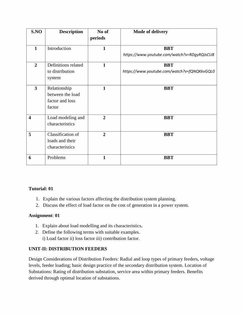
S.NO Description No of
periods
Mode of delivery
1 Introduction 1 BBT
https://www.youtube.com/watch?v=RDgyRQJsCU8
2 Definitions related
to distribution
system
1 BBT
https://www.youtube.com/watch?v=fQNQKkvGQL0
3 Relationship
between the load
factor and loss
factor
1 BBT
4 Load modeling and
characteristics
2 BBT
5 Classification of
loads and their
characteristics
2 BBT
6 Problems 1 BBT
Tutorial: 01
1. Explain the various factors affecting the distribution system planning.
2. Discuss the effect of load factor on the cost of generation in a power system.
Assignment: 01
1. Explain about load modelling and its characteristics.
2. Define the following terms with suitable examples.
i) Load factor ii) loss factor iii) contribution factor.
UNIT-II: DISTRIBUTION FEEDERS
Design Considerations of Distribution Feeders: Radial and loop types of primary feeders, voltage
levels, feeder loading; basic design practice of the secondary distribution system. Location of
Substations: Rating of distribution substation, service area within primary feeders. Benefits
derived through optimal location of substations.
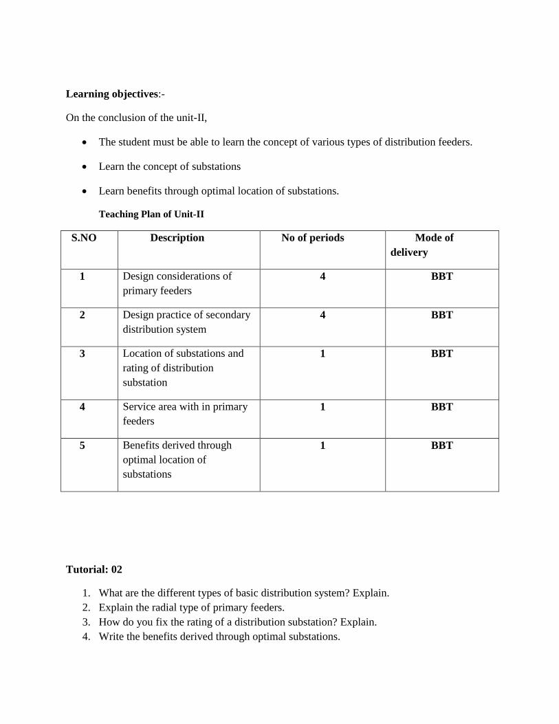
Learning objectives:-
On the conclusion of the unit-II,
The student must be able to learn the concept of various types of distribution feeders.
Learn the concept of substations
Learn benefits through optimal location of substations.
Teaching Plan of Unit-II
S.NO Description No of periods Mode of
delivery
1 Design considerations of
primary feeders
4 BBT
2 Design practice of secondary
distribution system
4 BBT
3 Location of substations and
rating of distribution
substation
1 BBT
4 Service area with in primary
feeders
1 BBT
5 Benefits derived through
optimal location of
substations
1 BBT
Tutorial: 02
1. What are the different types of basic distribution system? Explain.
2. Explain the radial type of primary feeders.
3. How do you fix the rating of a distribution substation? Explain.
4. Write the benefits derived through optimal substations.
Assignment: 02
1. What are the various factors that influence the voltage levels in the design and operation
of the distribution system?
2. Explain the basic design practice of the secondary distribution system.
3. Mention the various factors that are to be considered in selecting the ideal substations.
4. Explain about square shaped distribution substation areas.
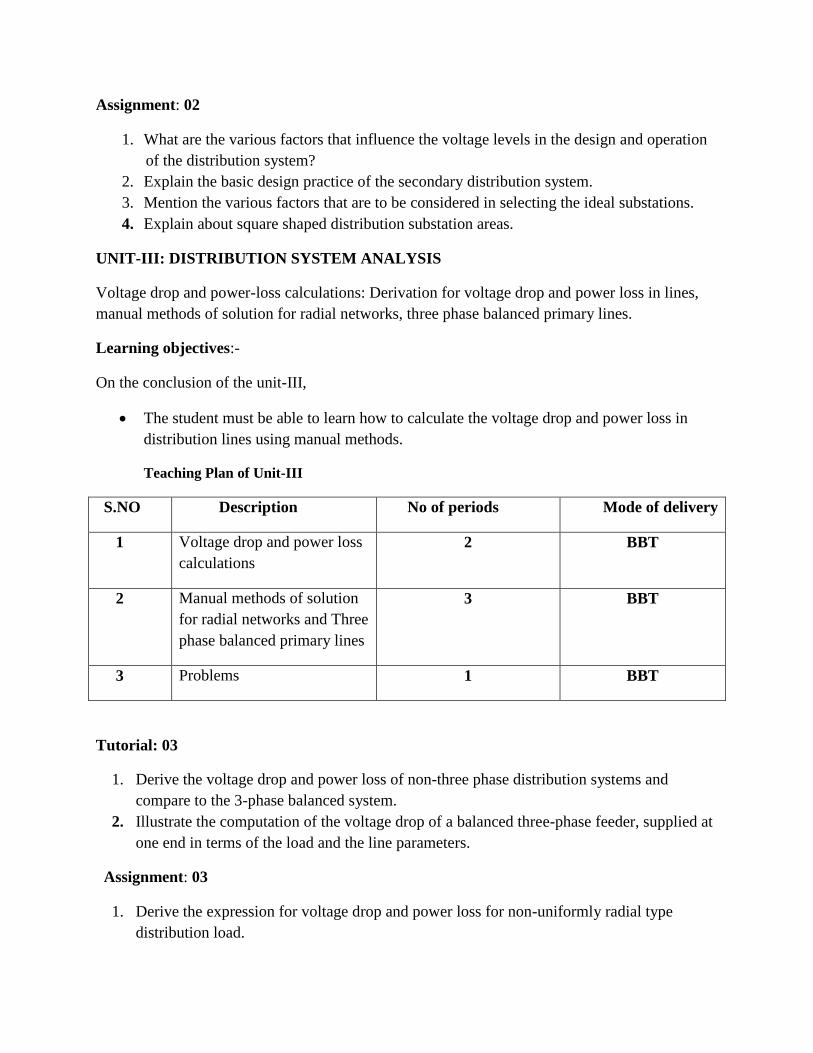
UNIT-III: DISTRIBUTION SYSTEM ANALYSIS
Voltage drop and power-loss calculations: Derivation for voltage drop and power loss in lines,
manual methods of solution for radial networks, three phase balanced primary lines.
Learning objectives:-
On the conclusion of the unit-III,
The student must be able to learn how to calculate the voltage drop and power loss in
distribution lines using manual methods.
Teaching Plan of Unit-III
S.NO Description No of periods Mode of delivery
1 Voltage drop and power loss
calculations
2 BBT
2 Manual methods of solution
for radial networks and Three
phase balanced primary lines
3 BBT
3 Problems 1 BBT
Tutorial: 03
1. Derive the voltage drop and power loss of non-three phase distribution systems and
compare to the 3-phase balanced system.
2. Illustrate the computation of the voltage drop of a balanced three-phase feeder, supplied at
one end in terms of the load and the line parameters.
Assignment: 03
1. Derive the expression for voltage drop and power loss for non-uniformly radial type
distribution load.
2. Derive the expression for the total series voltage drop and total copper loss per phase of a
uniformly distributed load. Give the assumptions made, if any.
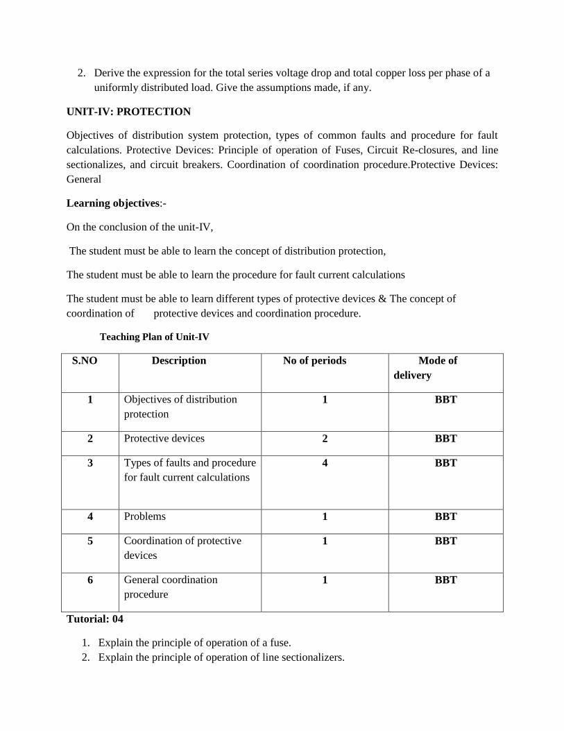
UNIT-IV: PROTECTION
Objectives of distribution system protection, types of common faults and procedure for fault
calculations. Protective Devices: Principle of operation of Fuses, Circuit Re-closures, and line
sectionalizes, and circuit breakers. Coordination of coordination procedure.Protective Devices:
General
Learning objectives:-
On the conclusion of the unit-IV,
The student must be able to learn the concept of distribution protection,
The student must be able to learn the procedure for fault current calculations
The student must be able to learn different types of protective devices & The concept of
coordination of protective devices and coordination procedure.
Teaching Plan of Unit-IV
S.NO Description No of periods Mode of
delivery
1 Objectives of distribution
protection
1 BBT
2 Protective devices 2 BBT
3 Types of faults and procedure
for fault current calculations
4 BBT
4 Problems 1 BBT
5 Coordination of protective
devices
1 BBT
6 General coordination
procedure
1 BBT
Tutorial: 04
1. Explain the principle of operation of a fuse.
2. Explain the principle of operation of line sectionalizers.
3. Explain the coordination procedure between re-closer and fuse.
4. What are the different types of coordination procedures?
Assignment: 04
1. What are the common types of faults that are occurring in the distribution system and
discuss.
2. Explain the principle of operation of circuit re-closers.
3. Explain the general coordination procedure of protective devices in radial distribution
systems.
4. Explain the differences between fuses and circuit breakers.
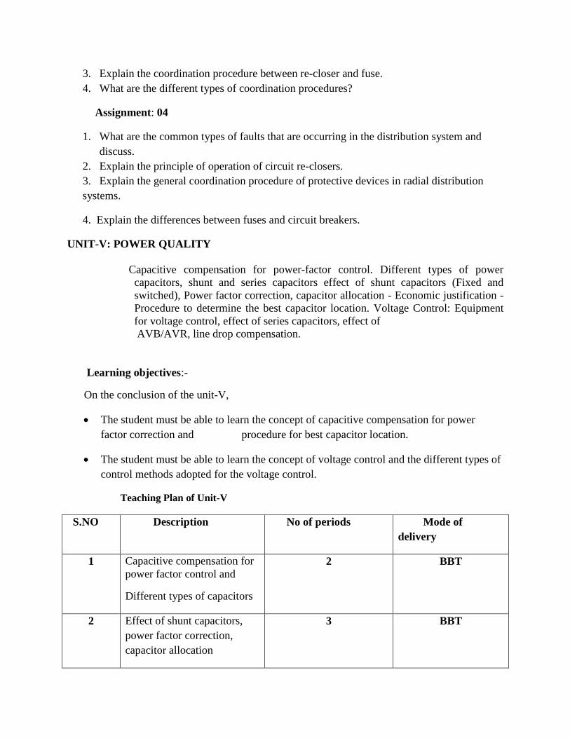
UNIT-V: POWER QUALITY
Capacitive compensation for power-factor control. Different types of power
capacitors, shunt and series capacitors effect of shunt capacitors (Fixed and
switched), Power factor correction, capacitor allocation - Economic justification -
Procedure to determine the best capacitor location. Voltage Control: Equipment
for voltage control, effect of series capacitors, effect of
AVB/AVR, line drop compensation.
Learning objectives:-
On the conclusion of the unit-V,
The student must be able to learn the concept of capacitive compensation for power
factor correction and procedure for best capacitor location.
The student must be able to learn the concept of voltage control and the different types of
control methods adopted for the voltage control.
Teaching Plan of Unit-V
S.NO Description No of periods Mode of
delivery
1 Capacitive compensation for
power factor control and
Different types of capacitors
2 BBT
2 Effect of shunt capacitors,
power factor correction,
capacitor allocation
3 BBT
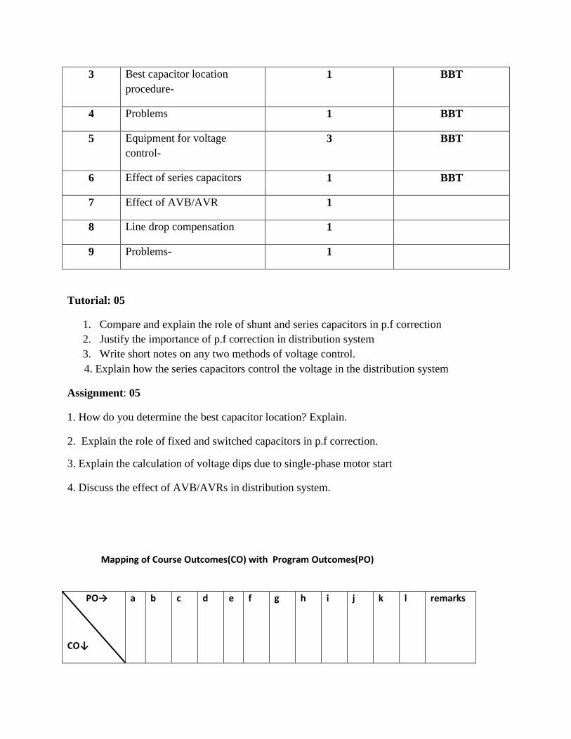
3 Best capacitor location
procedure-
1 BBT
4 Problems 1 BBT
5 Equipment for voltage
control-
3 BBT
6 Effect of series capacitors 1 BBT
7 Effect of AVB/AVR 1
8 Line drop compensation 1
9 Problems- 1
Tutorial: 05
1. Compare and explain the role of shunt and series capacitors in p.f correction
2. Justify the importance of p.f correction in distribution system
3. Write short notes on any two methods of voltage control.
4. Explain how the series capacitors control the voltage in the distribution system
Assignment: 05
1. How do you determine the best capacitor location? Explain.
2. Explain the role of fixed and switched capacitors in p.f correction.
3. Explain the calculation of voltage dips due to single-phase motor start
4. Discuss the effect of AVB/AVRs in distribution system.
Mapping of Course Outcomes(CO) with Program Outcomes(PO)
PO→
CO↓
a b c d e f g h i j k l remarks
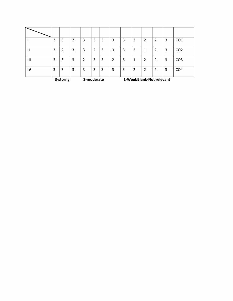
I 3 3 2 3 3 3 3 3 2 2 2 3 CO1
II 3 2 3 3 2 3 3 3 2 1 2 3 CO2
III 3 3 3 2 3 3 2 3 1 2 2 3 CO3
IV 3 3 3 3 3 3 3 3 2 2 2 3 CO4
3-storng 2-moderate 1-Week Blank-Not relevant
VNR VIGNANA JYOTHI INSTITUTE OF ENGINEERING & TECHNOLOGY
BACHUPALLY (VIA), KUKATPALLY, HYDERABAD – 72
DEPARTMENT OF ELECTRICAL & ELECTRONICS ENGINEERING
Learning Objectives for the Subject: ((13EEE107) ELECTRICAL MEASUREMENTS
&INSTRUMENTATION
Class: IV Year B.Tech. EEE – I Semester
Name of the Faculty: K.Ranjit Reddy & I.Neelima
(13EEE014) ELECTRICAL MEASUREMENTS & INSTRUMENTATION
UNIT-I
Measuring Instruments:
Classification – deflecting, Control and Damping Torques – PMMC, Moving iron type instruments –
Expression for the deflecting torque and control torque – Extension of range using shunts and series
resistance. Measurement of Power and Energy- Electrostatic Voltmeters
TEACHING PLAN
No. of periods required are 14
Introduction 1
Classification 1
Deflecting torque 1
Control and damping torques 1
PMMC 1
Moving iron type instruments 1
Expression for the deflecting torque and control 1
Torque – 1
Extension of range using shunts and series resistance 1
Electrostatic Voltmeters 1
Electrometer type Voltmeters 1
Attracted disc type Voltmeters 1
Measurement of Power 1
Learning Objectives:
After completion of Unit –I, student must be able to answer the following
Describe the classification of Deflecting torques. Explain about the PMMC. Derive the expression for deflecting torque. Explain different types of voltmeters.
ASSIGNMENT FOR UNIT -I
Explain the moving iron type instruments. Explain the Electrostatic Voltmeters & attracted disc type Voltmeters .
UNIT –II
Measurement of resistance, Inductance and capacitance: Method of measuring low, medium and high
resistance, insulation resistance measurements, AC bridges for Inductance and capacitance
Measurement, Merge
TEACHING PLAN
No. of periods required are 10
Method of measuring low 2
Medium and high resistance 2
Insulation resistance measurements 3
AC bridges for Inductance and capacitance Measurement, Merge 3
Learning Objectives:
After completion of Unit –VII, student must be able to answer the following
Explain the Measurement of inductance Quality Factor in A.C. bridges Explain Maxwell’s bridge Explain Hay’s bridge Explain Owen’s bridge. Explain Wien’s bridge
ASSIGNMENT FOR UNIT –II
Explian the Anderson’s bridge Explian the Schering Bridge Explain Schering Bridge .
UNIT –III
Instrument Transformers
Current and potential transfers, ratio and phase angle errors, testing. Potentio meters, AC and DC
Potentiometers, calibration of voltmeters and Ammeters.
TEACHING PLAN
No. of periods required are 12
Current and potential transfers 2
Ratio and phase angle errors 2
Testing 2
Potentio meters 2
AC and DC Potentiometers 2
Calibration of voltmeters and Ammeters 2
Learning Objectives :
After completion of Unit –V, student must be able to answer the following
Explain the Principle and operation of D.C. Crompton’s potentiometer . Explain about the Standardization. Explain about the A.C. Potentiometers
ASSIGNMENT FOR UNIT -III
Explian the Measurement of unknown resistance . Explian the polar and coordinate types standardization.
UNIT –IV
Electronic Measurements
Electronic voltmeter, multimeter, wattmeter &energy meter, Time, Frequency and phase angle
measurements using CRO; Spectrum & Wave analyzer. Digital counter, frequency meter, voltmeter,
multimeter and Storage Oscilloscope
TEACHING PLAN
No. of periods required are 15
Electronic voltmeter 2
Multimeter, wattmeter &energy meter 2
Time, Frequency and phase angle measurements using CRO 3
Spectrum & Wave analyzer. 2
Digital counter 2
Frequency meter voltmeter 2
Multimeter and Storage Oscilloscope 2
Learning Objectives:
After completion of Unit –IV, student must be able to answer the following
The following are the objectives which are learnt by the students
1. Draw the block diagram of CRO.
2. ----------- material used in the screen of CRO?
3. Explain the principle involved in sampling oscilloscopes.
4. Different types of CRO.
5. Advantages of digital CRO over analog CRO.
6. Principle of attenuation is used in.
7. Applications of CRO.
8. Describe the operation of cathode Ray Tube.
9. Define Lissajous figure.
10. Measurement of frequency in CRO is measured as--------.
11. Explain about different probes.
12. Define Sensitivity.
ASSIGNMENT FOR UNIT -IV
1. Draw the simplified diagram of sampling oscilloscope and explain. Draw the
Waveforms pertinent to operation?
2. Explain the functional block diagram of vertical deflection system in detail?
3. Draw the neat sketch of triggered sweep circuit and explain it. Draw the trigger pulse and
sweep waveforms?
4. Draw the block diagram of dual beam oscilloscope and explain its working?
UNIT – V
Instrumentation
Transducers, classification & selection of transducers, strain gauges, inductive & capacitive transducers,
piezoelectric and Hall-effect transducers, thermisters, thermocouples, photo-diodes & photo-transistors,
encoder type digital transducers, signal conditioning and telemetry, basic concepts of smart sensors and
application, data Acquisition Systems.
TEACHING PLAN
No. of periods required are 15
Transducers 1
Classification & selection of transducers, 2
Strain gauges 1
Inductive & capacitive transducers 2
Piezoelectric and Hall-effect transducers 2
Thermisters, thermocouples 1
Photo-diodes & photo-transistors 1
Encoder type digital transducers 1
Signal conditioning and telemetry 1
Basic concepts of smart sensors and application 2
Data Acquisition Systems 1
Learning Objectives:
The following are the objectives which are learnt by the students
1. Define Transducer 2. Classify the Transducer.
3. Advantages of Transducers.
4. Explain the Resistive Transducer.
5. Explain the Capacitive Transducers.
6. Explain the Inductive Transducers.
7. Principle involved in LVDT.
8. Define OFFSET.
9. Define Gauge Factor.
10. Derive an expression for the Gauge Factor.
11. Applications of strain gauges.
12. Explain about temperature measurement.
13. Acronym of RTD is-------
14. Principle of RTD.
15. RTD is --------- temperature coefficient.
16. Thermistor is ---------temperature coefficient.
17. Different Thermistor materials.
18. Different RTD materials.
19. Explain the LAWS of Thermocouple.
20. What is See back Effect.
21. What are different Piezo Crystals.
22. Principle in piezo electric transducers.
ASSIGNMENT FOR UNIT -V
1. What is an LVDT? Where it is used? Explain its operating principle?
2. Explain piezo electric effect? What are the materials that show piezo electric effect? Draw the
structure of piezo electric crystal?
3. Write short notes on resistive transducers?
4. Enumerate the principles behind an inductive transducer?
5. Name some common types of Strain Guages. What characteristics determine the size of
strain gauge?
6. Explain different types of Strain Gauges?
7. Draw the different forms of construction of Thermistors? Explain the salient features of
Thermistor?
TEXT BOOKS:
1. Electrical & Electronic Measurement & Instruments by A.K.Sawhney Dhanpat Rai & Sons
Publications.
2. ”modern Electronic Instrumentation and measurement Techniques”, Helfrick and cooper,
Prentice-Hall of India, Reprint 1988.
3.”Instrumentation Measurement and feedback”, Jones,B.E, Tata McGraw-Hill,1986.
REFERENCES:
1. Electrical Measurements and measuring Instruments – Golding,E.W,sir Issac Pitman and
sons,1960.
2. Buckingham, H. and Price, E.N.,” Principles of Electrical Measurements”,1961.
JAWAHARLAL NEHRU TECHNOLOGICAL UNIVERSITY,HYDERABAD
III Year B.Tech. EEE – I Semester
(EE 05198) ELECTRICAL MEASUREMENTS
MODEL PAPER 1
1 a) Explain with neat sketch , the working of a PMMC instrument.
b) What are the errors in a moving coil instrument . how these errors are compensated.
2. a) Describe the construction and working of a moving coil ballistic Galvano meter.
b) Describe the method of experimental measurement of flux density in a specimen of magnetic
material using ballistic galvanometer.
3 a ) A kelvin double bridge is balanced with the fallowing constants: outer ratio arm 100ohm & 1000
ohm ; inner ratio arms, 99.92ohm and 1000.6ohm; resistance of link 0.1 ohm, standard resistance
0.00377 ohm. Calculate the value of unknown resistance.
b) deduce the condition for balancing of bridges in ac bridges.
4.a)What are the different problems associated with measurement of low resistance.
b) How these problems are eliminated by using kelvin’s double bridge. Explain.
5. a) What are the methods of focus an electron beam ? what is a electron gun ?
b) How is electrostatic focusing done. Prove that the deflection is proportional to the deflecting
voltage.
b) How the value of ac permeability of magnetic material is determined by using maxwells’ bridge.
6. Explain piezo electric effect? What are the materials that show piezo electric effect? Draw the
Structure of piezo electric crystal?
7. (a).Write short notes on resistive transducers?
b). Enumerate the principles behind an inductive transducer?
8. (a).How do you measure the pressure by using electrical Transducer as Secondary Transducer?
(b). Define Torque? Different methods involved in measurement of Torque?
JAWAHARLAL NEHRU TECHNOLOGICAL UNIVERSITY,HYDERABADIII Year
B.Tech. EEE – I Semester (EE 05198) ELECTRICAL MEASUREMENTS
MODEL PAPER 2
1 a) describe with a neat diagram the construction and working of synchroscope.
b) describe with a neat diagram the construction andoperation of a vibrating reeds type frequency
meter.
2. a) desribe the method of measurement of reactive power in three phase circuits using single dynamo
meter type watt meter.
b) explain clearly how range of wattmeter can be extended using instrument transformer.
3. a) Distinguish between indicating recording, integrating, types of instruments.
b) explain the importance of torque to weight ratio , pivoted jewel bearings and types
supports with respect to indicating instruments.
4.draw a circuit diagram and explain the measurement of power using potentiometer.
5 a) what are the methods of focus an electron beam ? what is a electron gun ?
b) how is electrostatic focusing done. Prove that the deflection is proportional to the deflecting
voltage.
6 a) explain about vibrational galvano meter.
7 a) a kelvin double bridge is balanced with the fallowing constants:outer ratio arm 100ohm & 1000 ohm
; inner ratio arms, 99.92ohm and 1000.6ohm; resistance of link 0.1 ohm, standard resistance 0.00377
ohm. Calculate the value of unknown resistance.
b) deduce the condition for balancing of bridges in ac bridges.
8.a) describe the construction and working of a movingcoil ballistic galvano meter.
b) describe the method of experimental measurement of flux density in a specimen of magnetic
material using ballistic galvanometer.
JAWAHARLAL NEHRU TECHNOLOGICAL UNIVERSITY,HYDERABAD
III Year B.Tech. EEE – I Semester
(EE 05198) ELECTRICAL MEASUREMENTS
MODEL PAPER 3
1 a) Distinguish between indicating recording, integrating, types of instruments.
b) explain the importance of torque to weight ratio , pivoted jewel bearings and types
supports with respect to indicating instruments.
2. a) desribe the method of measurement of reactive power in three phase circuits using single
dynamo meter type watt meter.
b) explain clearly how range of wattmeter can be extended using instrument transformer.
3.a) describe with a neat diagram the construction and working of synchroscope.
b) describe with a neat diagram the construction and operation of a vibrating reeds type frequency
meter.
4. a)what are the different problems associated with measurement of low resistance.
b) how these problems are eliminated by using kelvin’s double bridge. Explain.
5. a) akelvin double bridge is balanced with the fallowing constants: outer ratio arm 100ohm & 1000
ohm ; inner ratio arms, 99.92ohm and 1000.6ohm; resistance of link 0.1 ohm, standard resistance
0.00377 ohm. Calculate the value of unknown resistance.
b) deduce the condition for balancing of bridges in ac bridges.
6 a) describe the method of measurement of iron lossw using lioyd fisher square.
b) how the value of ac permeability of magnetic material is determined by using maxwells’ bridge .
7 a) desribe the method of measurement of reactive power in three phase circuits using single dynamo
meter type watt meter.
b) explain clearly how range of wattmeter can be extended using instrument transformer.
8.a) explain with neat sketch , the working of a PMMC instrument.
b) what are the errors in a moving coil instrument . how these errors are compensated.
IV Year B. Tech EEE – I Sem L T/P/D C
4 1 4
Subject: High Voltage Engineering Subject Code:
Number of working days : 90
Number of Hours / week : 5
Total number of periods planned : 60
Name of the Faculty Member : G.Radhika
PREREQUISITES
13MTH001, 13MTH002, 13MTH005, 13PHY003, 13EEE001, 13ECE001, 13EEE101,
13ECE101
COURSE OBJECTIVES
1. To review the concept of dielectrics and their behavior under a High Voltage
2. To analyze methods for generation of High A.C, D.C & Impulse Voltages required for various
application.
3. To appraise the measuring techniques of High A.C., D.C & Impulse voltages and currents.
4. To impart the knowledge of testing techniques for High Voltage Equipment.
COURSE OUTCOMES
Upon completion of the syllabus student will be able to
1. Appraise the applications of solid, liquid and gaseous dielectrics in electrical
engineering.
2. To paraphrase the types of generation of High A.C, D.C & Impulse Voltages existing
in research centres all over the world.
3. Appreciate the necessity to measure the voltages and currents accurately, ensuring
perfect safety to the personnel and equipment.
4. Demonstrate the existing Testing techniques to test all the Electrical equipments
before commissioning into service.
MAPPING OF COs WITH POs
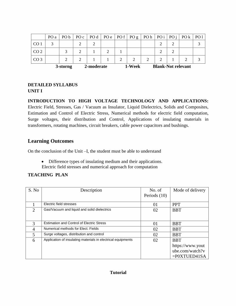
PO a PO b PO c PO d PO e PO f PO g PO h PO i PO j PO k PO l
CO 1 3
2 2
2 2
3
CO 2
3 2 1 2 1
2 2
CO 3
2 2 1 1 2 2 2 2 1 2 3
3-storng 2-moderate 1-Week Blank-Not relevant
DETAILED SYLLABUS
UNIT I
INTRODUCTION TO HIGH VOLTAGE TECHNOLOGY AND APPLICATIONS:
Electric Field, Stresses, Gas / Vacuum as Insulator, Liquid Dielectrics, Solids and Composites,
Estimation and Control of Electric Stress, Numerical methods for electric field computation,
Surge voltages, their distribution and Control, Applications of insulating materials in
transformers, rotating machines, circuit breakers, cable power capacitors and bushings.
Learning Outcomes
On the conclusion of the Unit –I, the student must be able to understand
Difference types of insulating medium and their applications.
Electric field stresses and numerical approach for computation
TEACHING PLAN
S. No Description No. of
Periods (10)
Mode of delivery
1 Electric field stresses 01 PPT
2 Gas/Vacuum and liquid and solid dielectrics 02 BBT
3 Estimation and Control of Electric Stress 01 BBT
4 Numerical methods for Elect. Fields 02 BBT
5 Surge voltages, distribution and control 02 BBT
6 Application of insulating materials in electrical equipments 02 BBT
https://www.yout
ube.com/watch?v
=P0XTUED41SA
Tutorial
1. Explain the operation SCR and its V-I Characteristics by defining i) Latching current
ii) Holding current iii) forward break over voltage iv)Reverse leakage current
2. Describe with neat sketch turn- on and turn – off characteristics of SCR
3. Explain the gate characteristics of a thyristor
4. Explain the necessity of series and parallel connection of SCRs
5. What is string efficiency in series and parallel connection of SCRs
Assignment
1. Explain the operation of power MOSFET with its characteristics
2. Compare the operation of BJT , Power MOSFET and power IGBT.
3. Explain the principle of natural and forced commutation circuits
4. What is the necessity of snubber circuits and how to choose the values R&C for dv/dt
snubber
5. Describe various triggering circuits of SCR
UNIT-II
UNIT II
BREAK DOWN IN GASEOUS AND LIQUID DIELECTRICS: Gases as insulating media,
collision process, Ionization process, Townsend’s criteria of breakdown in gases, Paschen’s law.
Liquid as Insulator, pure and commercial liquids, breakdown in pure and commercial liquids.
Intrinsic breakdown, electromechanical breakdown, thermal breakdown, breakdown of solid
dielectrics in practice, Breakdown in composite dielectrics, solid dielectrics used in practice.
Teaching plan:
S. Description No. of Mode of delivery
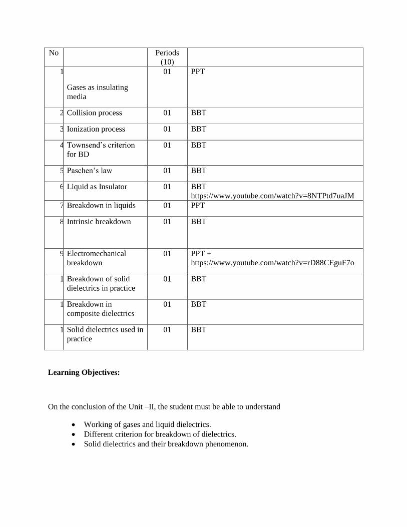
No Periods
(10)
1.
Gases as insulating
media
01 PPT
2. Collision process 01 BBT
3. Ionization process 01 BBT
4. Townsend’s criterion
for BD
01 BBT
5. Paschen’s law 01 BBT
6. Liquid as Insulator 01 BBT
https://www.youtube.com/watch?v=8NTPtd7uaJM
7. Breakdown in liquids 01 PPT
8. Intrinsic breakdown
01 BBT
9. Electromechanical
breakdown
01 PPT + https://www.youtube.com/watch?v=rD88CEguF7o
10. Breakdown of solid
dielectrics in practice
01 BBT
11. Breakdown in
composite dielectrics
01 BBT
12. Solid dielectrics used in
practice
01 BBT
Learning Objectives:
On the conclusion of the Unit –II, the student must be able to understand
Working of gases and liquid dielectrics.
Different criterion for breakdown of dielectrics.
Solid dielectrics and their breakdown phenomenon.
UNIT III
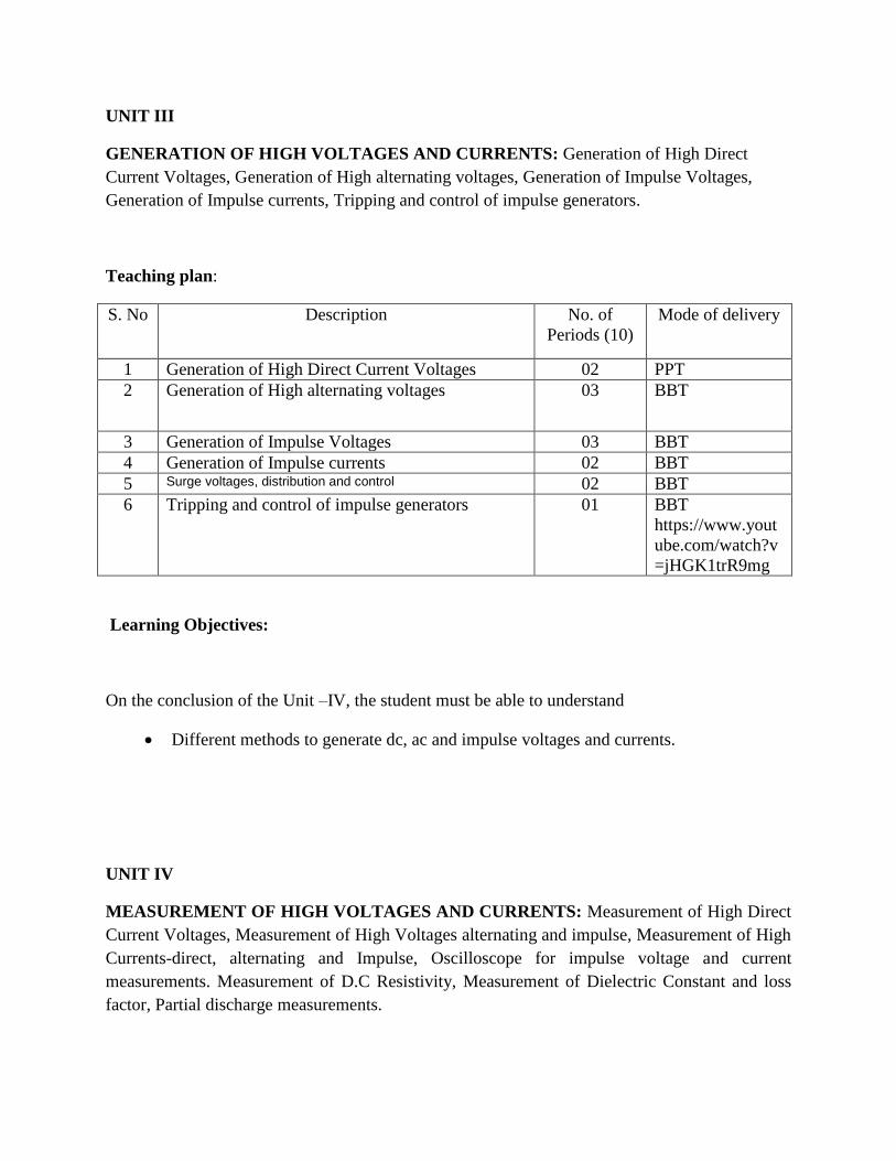
GENERATION OF HIGH VOLTAGES AND CURRENTS: Generation of High Direct
Current Voltages, Generation of High alternating voltages, Generation of Impulse Voltages,
Generation of Impulse currents, Tripping and control of impulse generators.
Teaching plan:
S. No Description No. of
Periods (10)
Mode of delivery
1 Generation of High Direct Current Voltages 02 PPT
2 Generation of High alternating voltages 03 BBT
3 Generation of Impulse Voltages 03 BBT
4 Generation of Impulse currents 02 BBT
5 Surge voltages, distribution and control 02 BBT
6 Tripping and control of impulse generators 01 BBT
https://www.yout
ube.com/watch?v
=jHGK1trR9mg
Learning Objectives:
On the conclusion of the Unit –IV, the student must be able to understand
Different methods to generate dc, ac and impulse voltages and currents.
UNIT IV
MEASUREMENT OF HIGH VOLTAGES AND CURRENTS: Measurement of High Direct
Current Voltages, Measurement of High Voltages alternating and impulse, Measurement of High
Currents-direct, alternating and Impulse, Oscilloscope for impulse voltage and current
measurements. Measurement of D.C Resistivity, Measurement of Dielectric Constant and loss
factor, Partial discharge measurements.
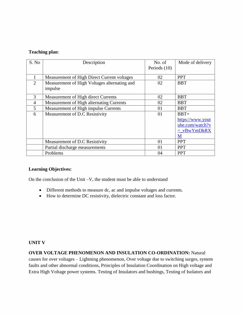
Teaching plan:
S. No Description No. of
Periods (10)
Mode of delivery
1 Measurement of High Direct Current voltages 02 PPT
2 Measurement of High Voltages alternating and
impulse
02 BBT
3 Measurement of High direct Currents 02 BBT
4 Measurement of High alternating Currents 02 BBT
5 Measurement of High impulse Currents 01 BBT
6 Measurement of D.C Resistivity 01 BBT+
https://www.yout
ube.com/watch?v
=_vBwYmDkRX
M
Measurement of D.C Resistivity 01 PPT
Partial discharge measurements 01 PPT
Problems 04 PPT
Learning Objectives:
On the conclusion of the Unit –V, the student must be able to understand
Different methods to measure dc, ac and impulse voltages and currents.
How to determine DC resistivity, dielectric constant and loss factor.
UNIT V
OVER VOLTAGE PHENOMENON AND INSULATION CO-ORDINATION: Natural
causes for over voltages – Lightning phenomenon, Over voltage due to switching surges, system
faults and other abnormal conditions, Principles of Insulation Coordination on High voltage and
Extra High Voltage power systems. Testing of Insulators and bushings, Testing of Isolators and
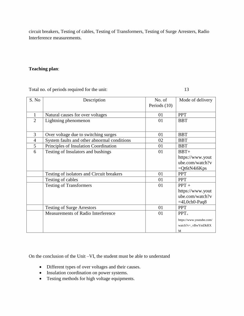
circuit breakers, Testing of cables, Testing of Transformers, Testing of Surge Arresters, Radio
Interference measurements.
Teaching plan:
Total no. of periods required for the unit: 13
S. No Description No. of
Periods (10)
Mode of delivery
1 Natural causes for over voltages 01 PPT
2 Lightning phenomenon 01 BBT
3 Over voltage due to switching surges 01 BBT
4 System faults and other abnormal conditions 02 BBT
5 Principles of Insulation Coordination 01 BBT
6 Testing of Insulators and bushings 01 BBT+
https://www.yout
ube.com/watch?v
=Qt6tN4i6Kps
Testing of isolators and Circuit breakers 01 PPT
Testing of cables 01 PPT
Testing of Transformers 01 PPT +
https://www.yout
ube.com/watch?v
=4L0ch0-Paq8
Testing of Surge Arrestors 01 PPT
Measurements of Radio Interference 01 PPT+
https://www.youtube.com/
watch?v=_vBwYmDkRX
M
On the conclusion of the Unit –VI, the student must be able to understand
Different types of over voltages and their causes.
Insulation coordination on power systems.
Testing methods for high voltage equipments.
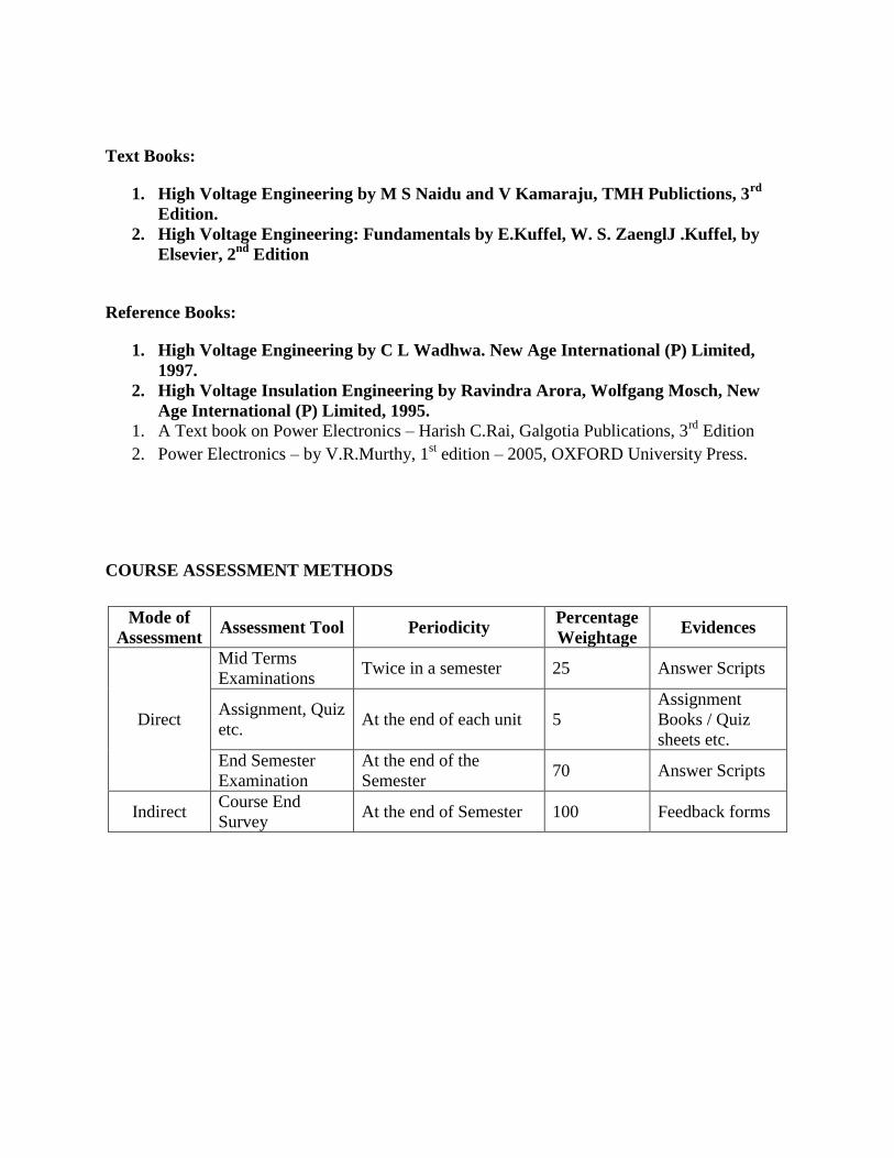
Text Books:
1. High Voltage Engineering by M S Naidu and V Kamaraju, TMH Publictions, 3rd
Edition.
2. High Voltage Engineering: Fundamentals by E.Kuffel, W. S. ZaenglJ .Kuffel, by
Elsevier, 2nd
Edition
Reference Books:
1. High Voltage Engineering by C L Wadhwa. New Age International (P) Limited,
1997.
2. High Voltage Insulation Engineering by Ravindra Arora, Wolfgang Mosch, New
Age International (P) Limited, 1995.
1. A Text book on Power Electronics – Harish C.Rai, Galgotia Publications, 3rd
Edition
2. Power Electronics – by V.R.Murthy, 1st edition – 2005, OXFORD University Press.
COURSE ASSESSMENT METHODS
Mode of
Assessment Assessment Tool Periodicity
Percentage
Weightage Evidences
Direct
Mid Terms
Examinations Twice in a semester 25 Answer Scripts
Assignment, Quiz
etc. At the end of each unit 5
Assignment
Books / Quiz
sheets etc.
End Semester
Examination
At the end of the
Semester 70 Answer Scripts
Indirect Course End
Survey At the end of Semester 100 Feedback forms
Academic Planning
for the subject of
Power System Operation & Control
IV - B.Tech, I-semester, EEE (R-13)
Dr.T. Nireekshana
Assistant Professor
D.S.G.Krishna
Assistant Professor
EEE Dept.
Subject code: 13EEE016
No. of Lectures Planned Per week : 5
No. of Lectures Planned Per semester : 80
Course Outcomes:
CO1: Computing the optimal scheduling of power plants
CO2:Analyze the steady state behaviour of the power system for voltage and frequency
fluctuations CO3: Describe reactive power control of a power system
CO4: Design suitable controller to dampen the frequency and voltage steady state oscillations
UNIT –I
Syllabus:
Economic Operation of Power Systems : Optimal operation of Generators in Thermal Power Stations, -
heat rate Curve – Cost Curve – Incremental fuel and Production costs, input-output characteristics,
Optimum generation allocation with line losses neglected. Optimum generation allocation including the
effect of transmission line losses – Loss Coefficients, General transmission line loss formula.
Lecture Plan :
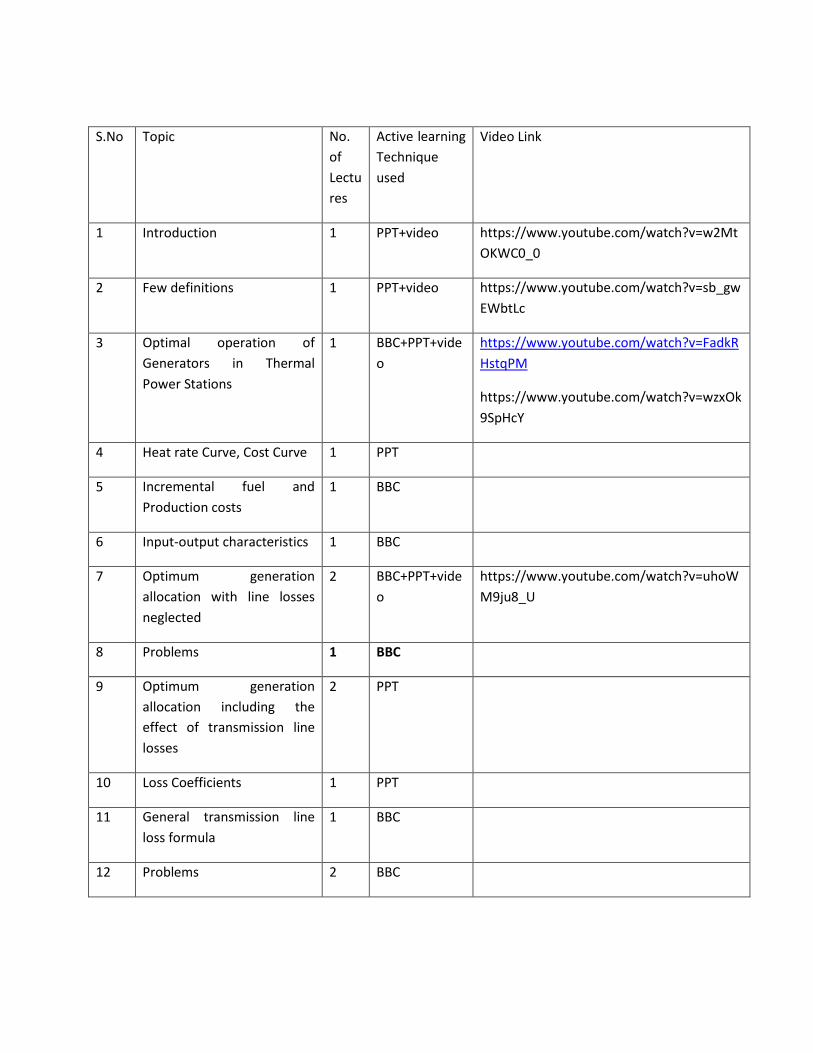
S.No Topic No.
of
Lectu
res
Active learning
Technique
used
Video Link
1 Introduction 1 PPT+video https://www.youtube.com/watch?v=w2Mt
OKWC0_0
2 Few definitions 1 PPT+video https://www.youtube.com/watch?v=sb_gw
EWbtLc
3 Optimal operation of
Generators in Thermal
Power Stations
1 BBC+PPT+vide
o
https://www.youtube.com/watch?v=FadkR
HstqPM
https://www.youtube.com/watch?v=wzxOk
9SpHcY
4 Heat rate Curve, Cost Curve 1 PPT
5 Incremental fuel and
Production costs
1 BBC
6 Input-output characteristics 1 BBC
7 Optimum generation
allocation with line losses
neglected
2 BBC+PPT+vide
o
https://www.youtube.com/watch?v=uhoW
M9ju8_U
8 Problems 1 BBC
9 Optimum generation
allocation including the
effect of transmission line
losses
2 PPT
10 Loss Coefficients 1 PPT
11 General transmission line
loss formula
1 BBC
12 Problems 2 BBC
Assignment 1:
1. Classify the generators according to their load factors.
2. Why economic operation is exercised for only thermal stations ?
3. Explain Heat Rate Curve, Cost Curve
4. What is an Incremental fuel Cost and its significance?
5. Derive the general condition for Optimum generation allocation with line losses neglected
6. Derive the general condition for Optimum generation allocation with line losses neglected
7. Derive the general loss formula or B-coefficients.
8. Determine saving in the fuel cost in Rs/Hour for the economic distribution of total load of 110 MW between two units having following incremental fuel cost characteristics,in comparison with equal distribution of same total load between two units.
= Rs/MWhr
= Rs/MWhr
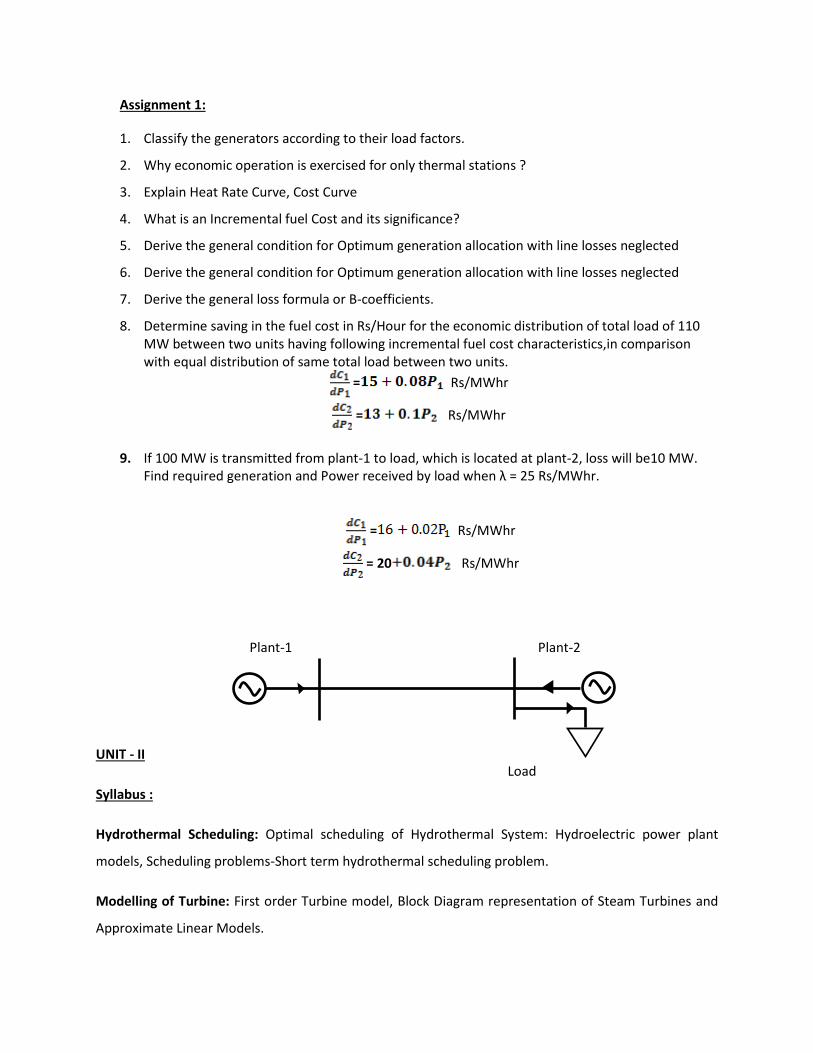
9. If 100 MW is transmitted from plant-1 to load, which is located at plant-2, loss will be10 MW. Find required generation and Power received by load when λ = 25 Rs/MWhr.
= Rs/MWhr
= 20 Rs/MWhr
UNIT - II
Syllabus :
Hydrothermal Scheduling: Optimal scheduling of Hydrothermal System: Hydroelectric power plant
models, Scheduling problems-Short term hydrothermal scheduling problem.
Modelling of Turbine: First order Turbine model, Block Diagram representation of Steam Turbines and
Approximate Linear Models.
Plant-1 Plant-2
Load
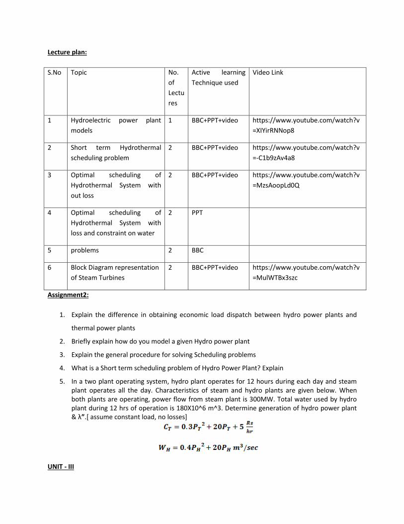
Lecture plan:
S.No Topic No.
of
Lectu
res
Active learning
Technique used
Video Link
1 Hydroelectric power plant
models
1 BBC+PPT+video https://www.youtube.com/watch?v
=XIYirRNNop8
2 Short term Hydrothermal
scheduling problem
2 BBC+PPT+video https://www.youtube.com/watch?v
=-C1b9zAv4a8
3 Optimal scheduling of
Hydrothermal System with
out loss
2 BBC+PPT+video https://www.youtube.com/watch?v
=MzsAoopLd0Q
4 Optimal scheduling of
Hydrothermal System with
loss and constraint on water
2 PPT
5 problems 2 BBC
6 Block Diagram representation
of Steam Turbines
2 BBC+PPT+video https://www.youtube.com/watch?v
=MulWTBx3szc
Assignment2:
1. Explain the difference in obtaining economic load dispatch between hydro power plants and
thermal power plants
2. Briefly explain how do you model a given Hydro power plant
3. Explain the general procedure for solving Scheduling problems
4. What is a Short term scheduling problem of Hydro Power Plant? Explain
5. In a two plant operating system, hydro plant operates for 12 hours during each day and steam plant operates all the day. Characteristics of steam and hydro plants are given below. When both plants are operating, power flow from steam plant is 300MW. Total water used by hydro plant during 12 hrs of operation is 180X10^6 m^3. Determine generation of hydro power plant & λ”.[ assume constant load, no losses]
UNIT - III
Syllabus :
Modelling of Generator (Steady State and Transient Models): Description of Simplified Network Model
of a Synchronous Machine (Classical Model), Description of Swing Equation ( No Derivation) and State-
Space II-Order Mathematical Model of Synchronous Machine.
Modelling of Governor: Mathematical Modelling of Speed Governing System – Derivation of small signal
transfer function.
Modelling of Excitation System : Fundamental Characteristics of an Excitation system, Transfer function,
Block Diagram Representation of IEEE Type-1 Model
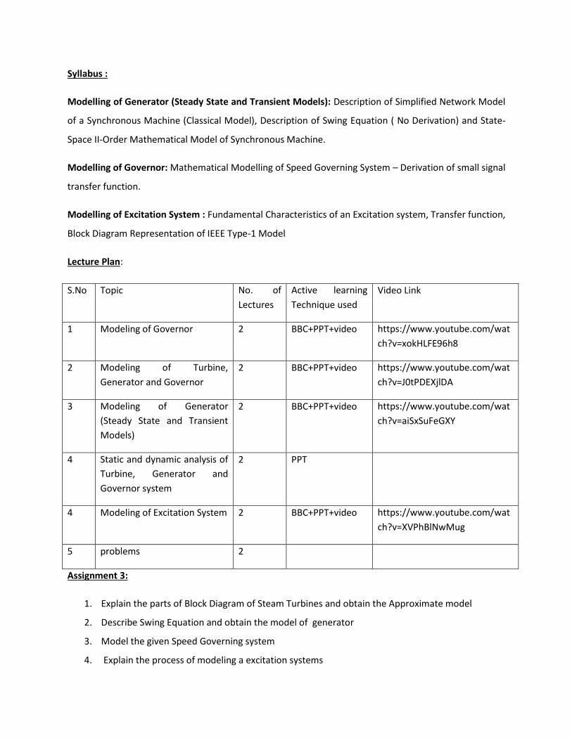
Lecture Plan:
S.No Topic No. of
Lectures
Active learning
Technique used
Video Link
1 Modeling of Governor 2 BBC+PPT+video https://www.youtube.com/wat
ch?v=xokHLFE96h8
2 Modeling of Turbine,
Generator and Governor
2 BBC+PPT+video https://www.youtube.com/wat
ch?v=J0tPDEXjlDA
3 Modeling of Generator
(Steady State and Transient
Models)
2 BBC+PPT+video https://www.youtube.com/wat
ch?v=aiSxSuFeGXY
4 Static and dynamic analysis of
Turbine, Generator and
Governor system
2 PPT
4 Modeling of Excitation System 2 BBC+PPT+video https://www.youtube.com/wat
ch?v=XVPhBlNwMug
5 problems 2
Assignment 3:
1. Explain the parts of Block Diagram of Steam Turbines and obtain the Approximate model
2. Describe Swing Equation and obtain the model of generator
3. Model the given Speed Governing system
4. Explain the process of modeling a excitation systems
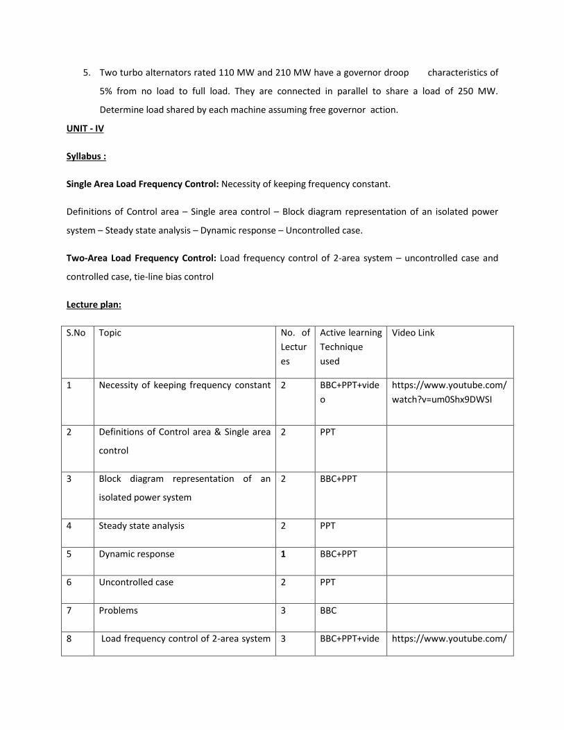
5. Two turbo alternators rated 110 MW and 210 MW have a governor droop characteristics of
5% from no load to full load. They are connected in parallel to share a load of 250 MW.
Determine load shared by each machine assuming free governor action.
UNIT - IV
Syllabus :
Single Area Load Frequency Control: Necessity of keeping frequency constant.
Definitions of Control area – Single area control – Block diagram representation of an isolated power
system – Steady state analysis – Dynamic response – Uncontrolled case.
Two-Area Load Frequency Control: Load frequency control of 2-area system – uncontrolled case and
controlled case, tie-line bias control
Lecture plan:
S.No Topic No. of
Lectur
es
Active learning
Technique
used
Video Link
1 Necessity of keeping frequency constant
2 BBC+PPT+vide
o
https://www.youtube.com/
watch?v=um0Shx9DWSI
2 Definitions of Control area & Single area
control
2 PPT
3 Block diagram representation of an
isolated power system
2 BBC+PPT
4 Steady state analysis 2 PPT
5 Dynamic response 1 BBC+PPT
6 Uncontrolled case 2 PPT
7 Problems 3 BBC
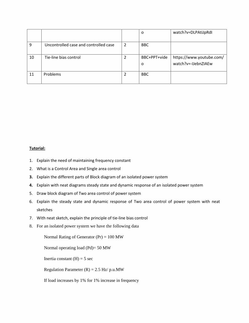
8 Load frequency control of 2-area system 3 BBC+PPT+vide https://www.youtube.com/
o watch?v=DLPAtiJpRdI
9 Uncontrolled case and controlled case 2 BBC
10 Tie-line bias control 2 BBC+PPT+vide
o
https://www.youtube.com/
watch?v=-IJebnZIAEw
11 Problems 2 BBC
Tutorial:
1. Explain the need of maintaining frequency constant
2. What is a Control Area and Single area control
3. Explain the different parts of Block diagram of an isolated power system
4. Explain with neat diagrams steady state and dynamic response of an isolated power system
5. Draw block diagram of Two area control of power system
6. Explain the steady state and dynamic response of Two area control of power system with neat
sketches
7. With neat sketch, explain the principle of tie-line bias control
8. For an isolated power system we have the following data
Normal Rating of Generator (Pr) = 100 MW
Normal operating load (Pd)= 50 MW
Inertia constant (H) = 5 sec
Regulation Parameter (R) = 2.5 Hz/ p.u.MW
If load increases by 1% for 1% increase in frequency
i) Find the frequency drop if the load increases by 10 MW
In what proportion increase in load demand is met by increase in generation.
9. Two inter connected areas 1 and 2 have the capacity of 1500 MW and 500 MW respectively. The
incremental regulation and damping torque co-efficient for each area on its own base are 0.1 p.u. and
1.0 p.u. Find the steady state change in system frequency from a nominal frequency of 50 Hz and change
in tie line power following 50 MW load change in Area-1.
UNIT - V
Syllabus :
Load Frequency Controllers: Proportional plus Integral control of single area and its block diagram
representation, steady state response – Load Frequency Control and Economic dispatch control.
Reactive Power Control: Overview of Reactive Power control – Reactive Power compensation in
transmission systems – advantages and disadvantages of different types of compensating equipment for
transmission systems; load compensation – Specifications of load compensator, Uncompensated and
compensated transmission lines: shunt and Series Compensation.
S.No Topic No. of
Lectur
es
Active
learning
Technique
used
Video Link
1 Proportional plus Integral controllers 3 PPT
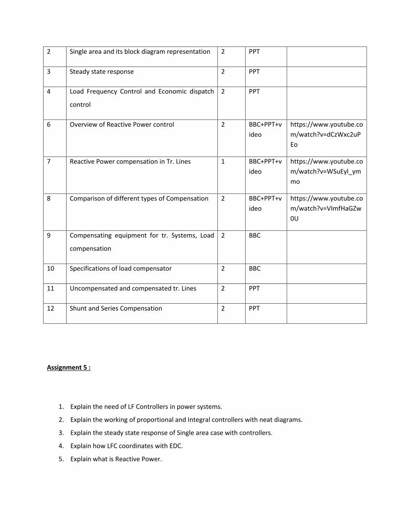
2 Single area and its block diagram representation 2 PPT
3 Steady state response 2 PPT
4 Load Frequency Control and Economic dispatch
control
2 PPT
6 Overview of Reactive Power control 2 BBC+PPT+v
ideo
https://www.youtube.co
m/watch?v=dCzWxc2uP
Eo
7 Reactive Power compensation in Tr. Lines 1 BBC+PPT+v
ideo
https://www.youtube.co
m/watch?v=WSuEyl_ym
mo
8 Comparison of different types of Compensation 2 BBC+PPT+v
ideo
https://www.youtube.co
m/watch?v=VImfHaGZw
0U
9 Compensating equipment for tr. Systems, Load
compensation
2 BBC
10 Specifications of load compensator 2 BBC
11 Uncompensated and compensated tr. Lines 2 PPT
12 Shunt and Series Compensation 2 PPT
Assignment 5 :
1. Explain the need of LF Controllers in power systems.
2. Explain the working of proportional and Integral controllers with neat diagrams.
3. Explain the steady state response of Single area case with controllers.
4. Explain how LFC coordinates with EDC.
5. Explain what is Reactive Power.
6. Explain the negative effects of reactive power flow in tr. Lines.
7. Compare different types of compensators.
8. What is the difference between load compensation and line compensation.
9. Explain the difference between Shunt compensation and Seies Compensation.
TEXT BOOKS :
1. Electric Energy systems Theory – by O.I.Elgerd, Tata Mc Graw-hill Publishing Comapany Ltd., Second
edition.
2. Modern Power System Analysis – by I.J.Nagrath & D.P.Kothari Tata M Graw – Hill Publishing Company
Ltd, 2nd edition.
REFERENCES :
1. Power System Analysis and Design by J.Duncan Glover and M.S.Sarma., THOMPSON, 3rd Edition.
2. Electric Power systems – by B.M.Weedy, B.J.Cary 4th Edition , Wiley.
3. Economic Operation of Power systems – by L.K.Kirchmayer, Wiley Eastern Ltd.
4. Power System Analysis by N.V.Ramana and N.Yadaiah, Pearson Education.
5. Electric Energy systems Theory – by O.I.Elgerd, Tata Mc Graw-hill Publishing Comapany Ltd., Second
edition.
VNR VIGNANA JYOTHI INSTITUTE OF ENGINEERING & TECHNOLOGY
IV-B.Tech (EEE)-I-Semester, End examinations(R-11)
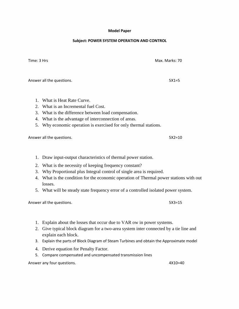
Model Paper
Subject: POWER SYSTEM OPERATION AND CONTROL
Time: 3 Hrs Max. Marks: 70
Answer all the questions. 5X1=5
1. What is Heat Rate Curve.
2. What is an Incremental fuel Cost.
3. What is the difference between load compensation.
4. What is the advantage of interconnection of areas.
5. Why economic operation is exercised for only thermal stations.
Answer all the questions. 5X2=10
1. Draw input-output characteristics of thermal power station.
2. What is the necessity of keeping frequency constant?
3. Why Proportional plus Integral control of single area is required.
4. What is the condition for the economic operation of Thermal power stations with out
losses.
5. What will be steady state frequency error of a controlled isolated power system.
Answer all the questions. 5X3=15
1. Explain about the losses that occur due to VAR ow in power systems.
2. Give typical block diagram for a two-area system inter connected by a tie line and
explain each block.
3. Explain the parts of Block Diagram of Steam Turbines and obtain the Approximate model
4. Derive equation for Penalty Factor.
5. Compare compensated and uncompensated transmission lines
Answer any four questions. 4X10=40
1. a) Give algorithm for economic allocation of generators of thermal system taking
transmission losses into account. Give steps for implementing this algorithm with necessary
equations.
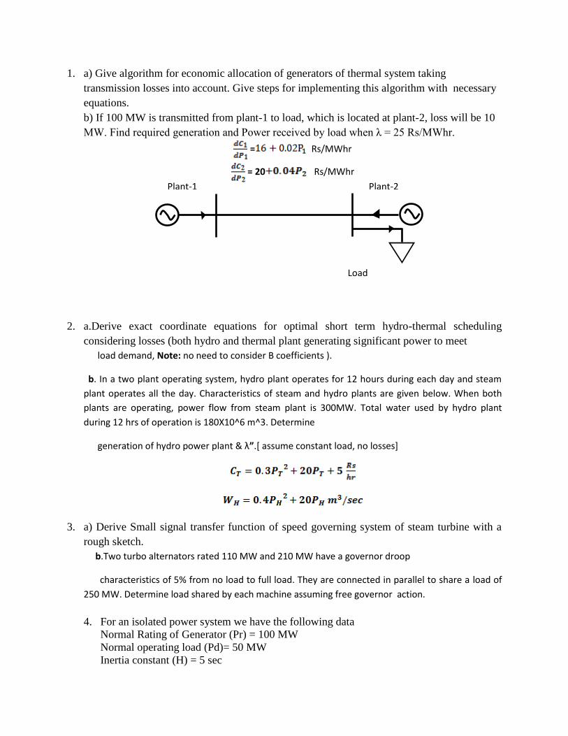
b) If 100 MW is transmitted from plant-1 to load, which is located at plant-2, loss will be 10
MW. Find required generation and Power received by load when λ = 25 Rs/MWhr.
= Rs/MWhr
= 20 Rs/MWhr
2. a.Derive exact coordinate equations for optimal short term hydro-thermal scheduling
considering losses (both hydro and thermal plant generating significant power to meet
load demand, Note: no need to consider B coefficients ).
b. In a two plant operating system, hydro plant operates for 12 hours during each day and steam
plant operates all the day. Characteristics of steam and hydro plants are given below. When both
plants are operating, power flow from steam plant is 300MW. Total water used by hydro plant
during 12 hrs of operation is 180X10^6 m^3. Determine
generation of hydro power plant & λ”.[ assume constant load, no losses]
3. a) Derive Small signal transfer function of speed governing system of steam turbine with a
rough sketch.
b.Two turbo alternators rated 110 MW and 210 MW have a governor droop
characteristics of 5% from no load to full load. They are connected in parallel to share a load of
250 MW. Determine load shared by each machine assuming free governor action.
4. For an isolated power system we have the following data
Normal Rating of Generator (Pr) = 100 MW
Normal operating load (Pd)= 50 MW
Inertia constant (H) = 5 sec
Plant-1 Plant-2
Load
Regulation Parameter (R) = 2.5 Hz/ p.u.MW
If load increases by 1% for 1% increase in frequency
ii) Find the frequency drop if the load increases by 10 MW
iii) In what proportion increase in load demand is met by increase in generation.
5. a) Give the block diagram of Tie-line bias controlled two area system
b) Derive expression for Tie line power for an uncontrolled two area system.
6. a)How the following devices generate/absorb reactive power.
i) Synchronous machine
ii) Over head lines
iii) Shunt reactor
b) Two inter connected areas 1 and 2 have the capacity of 1500 MW and 500 MW
respectively. The incremental regulation and damping torque co-efficient for each area on its
own base are 0.1 p.u. and 1.0 p.u. Find the steady state change in system frequency from a
nominal frequency of 50 Hz and change in tie line power following 50 MW load change in
Area-1.