understand copper wire bond...
TRANSCRIPT
External Use
TM
Understand Copper Wire
Bond Technology
FTF-SDS-F0022
A P R . 2 0 1 4
Leo M. Higgins III, Ph. D. | Distinguished Member Technical Staff

TM
External Use 1
Agenda
• What is Wire Bonding?
• Strategy and Background
• Key Development Challenges and Results
• Assembly Optimization for High Volume Mfg
• Sample Reliability Data and Electrical Performance
• FSL Cu Wire Products in Production
• Summary

TM
External Use 3
Agenda
• What is Wire Bonding?
• Strategy and Background
• Key Development Challenges and Results
• Assembly Optimization for High Volume Mfg
• Sample Reliability Data and Electrical Performance
• FSL Cu Wire Products in Production
• Summary

TM
External Use 4
Cu Bond Wire Strategy
• FSL has converted Consumer / Industrial microcontrollers to Cu wire and are now initiating Automotive conversions.
− Both Gold (Au) and Copper (Cu) wire have been used for wire bonding to Aluminum (Al) bond pads on ICs for many years
Intermetallic compound (IMC) formation provides adhesion between wires and pad
− Recent wire bond (WB) technology advancements are expanding the use of Cu wire.
• Motivation
− Some new products require a high temperature application for which Cu wire is the best solution.
− Avoids the need to pass on increased Au wire costs.
• Introduction / Change Strategy
− All new products will be introduced with Cu wire
− All Fab expansion products will be qualified with Cu wire
− Existing product families will migrate to Cu wire
Some legacy products will migrate to thinner Au wire

TM
External Use 6
Agenda
• What is Wire Bonding?
• Strategy and Background
• Key Development Challenges and Results
• Assembly Optimization for High Volume Mfg
• Sample Reliability Data and Electrical Performance
• FSL Cu Wire Products in Production
• Summary
TM
External Use 8
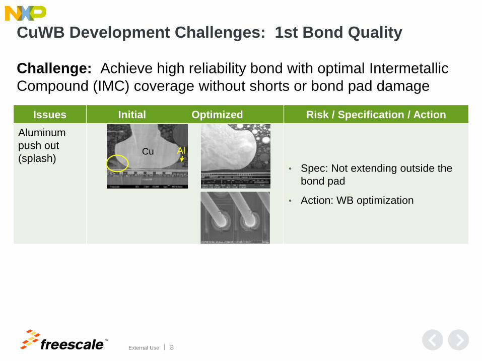
Issues Initial Optimized Risk / Specification / Action
Aluminum
push out
(splash) • Spec: Not extending outside the
bond pad
• Action: WB optimization
Cu Al
CuWB Development Challenges: 1st Bond Quality
Challenge: Achieve high reliability bond with optimal Intermetallic
Compound (IMC) coverage without shorts or bond pad damage
TM
External Use 9
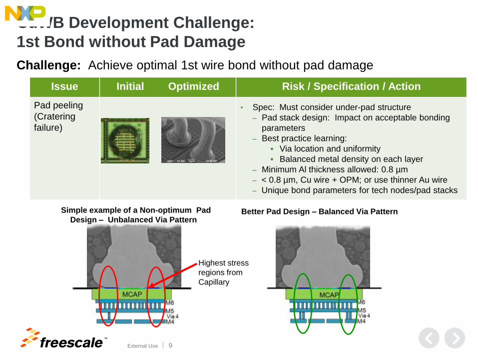
CuWB Development Challenge:
1st Bond without Pad Damage
Challenge: Achieve optimal 1st wire bond without pad damage
Issue Initial Optimized Risk / Specification / Action
Pad peeling
(Cratering
failure)
• Spec: Must consider under-pad structure
‒ Pad stack design: Impact on acceptable bonding
parameters
‒ Best practice learning:
Via location and uniformity
Balanced metal density on each layer
‒ Minimum Al thickness allowed: 0.8 µm
‒ < 0.8 µm, Cu wire + OPM; or use thinner Au wire
‒ Unique bond parameters for tech nodes/pad stacks
Simple example of a Non-optimum Pad
Design – Unbalanced Via Pattern Better Pad Design – Balanced Via Pattern
Highest stress
regions from
Capillary
TM
External Use 10
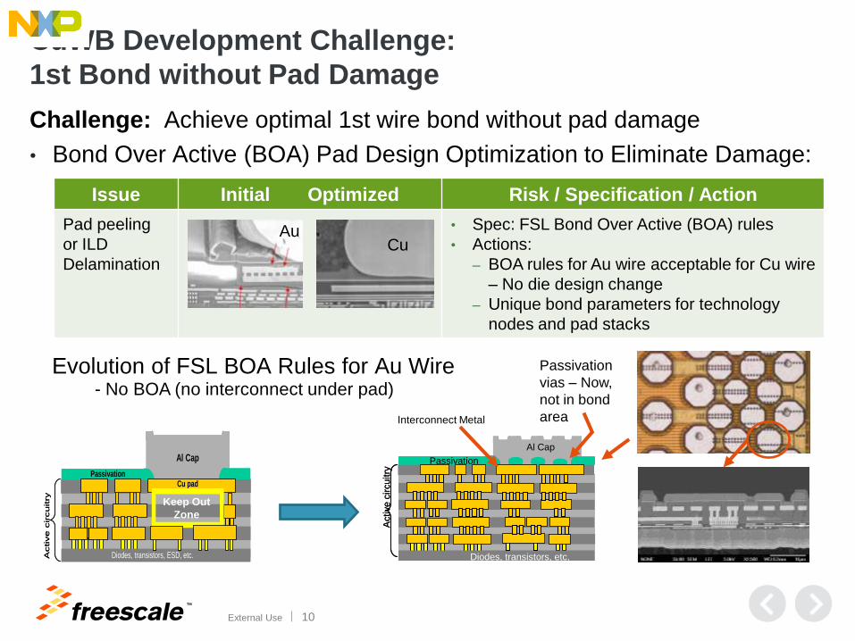
CuWB Development Challenge:
1st Bond without Pad Damage
Challenge: Achieve optimal 1st wire bond without pad damage
• Bond Over Active (BOA) Pad Design Optimization to Eliminate Damage:
Issue Initial Optimized Risk / Specification / Action
Pad peeling
or ILD
Delamination
• Spec: FSL Bond Over Active (BOA) rules
• Actions:
‒ BOA rules for Au wire acceptable for Cu wire
– No die design change
‒ Unique bond parameters for technology
nodes and pad stacks
Au Cu
Al Cap
Cu padPassivation
Diodes, transistors, ESD, etc.Active c
ircuitry
Al Cap
Cu padPassivation
Diodes, transistors, ESD, etc.Active c
ircuitry Keep Out
Zone
Al Cap
Passivation
Diodes, transistors, etc.
Active c
ircuitry
Al Cap
Passivation
Diodes, transistors, etc.
Active c
ircuitry
Interconnect Metal
Passivation
vias – Now,
not in bond
area
Evolution of FSL BOA Rules for Au Wire - No BOA (no interconnect under pad)

TM
External Use 11
Issues Initial Optimized Risk / Specification / Action
Cu-Al
Intermetallic
(IMC) bond layer
corrosion (biased
HAST failure)
• FSL specifies pH and Cl-
• Action: Internal testing demonstrates
higher pH and lower Cl- are best for
CuWB reliability.
‒ FSL tightened MC specification for
Au wire to meet CuWB requirement Corrosion crack
Cu
Al
Solid IMC
Cu
Al
CuWB Development Challenges: 1st Bond IMC Corrosion
Challenge: Avoid 1st bond IMC corrosion to pass Biased HAST / THB reliability tests
• Chloride (Cl-), principally from mold compound, can cause corrosion at the Cu ball to IMC interface resulting in open circuits
• Goal to use same BOM for CuWB and AuWB, including molding compound (MC)
• Internal research developed methods to determine acceptable pH and Cl- levels within ranges specified by suppliers
• Specs often renegotiated with suppliers to allow same MC used for AuWB
• Universal pH and Cl- level spec with reasonable values is not possible
• Acceptable pH and Cl- levels vary among MCs due to other MC attributes
• Acceptable pH and Cl- levels vary with voltage
TM
External Use 12
Fail
Pas
s
Low Medium High
Low
M
ediu
m
Hig
h
≥ 65V
Pass ≥ 3V
3V
3V
5V
5V Pass ≥ 5V 14V
Pass ≥ 3V
Fails
Pass ≥65V
Pass ≥5V
Pass ≥3V
14V Pass ≥ 3V
Pass ≥ 5V
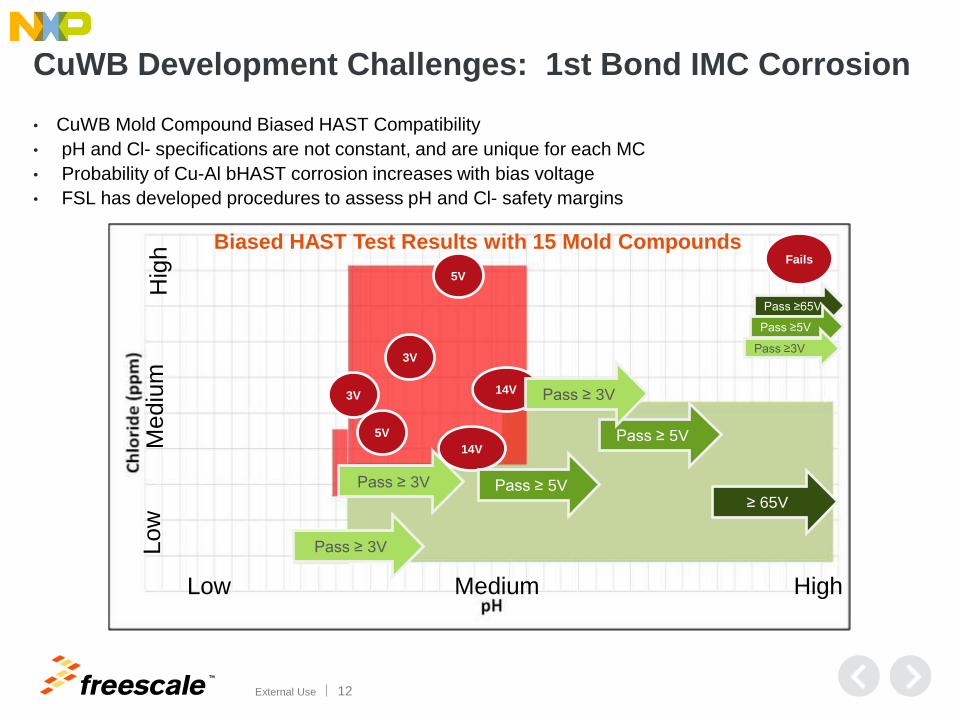
Biased HAST Test Results with 15 Mold Compounds
CuWB Development Challenges: 1st Bond IMC Corrosion
• CuWB Mold Compound Biased HAST Compatibility
• pH and Cl- specifications are not constant, and are unique for each MC
• Probability of Cu-Al bHAST corrosion increases with bias voltage
• FSL has developed procedures to assess pH and Cl- safety margins
TM
External Use 13
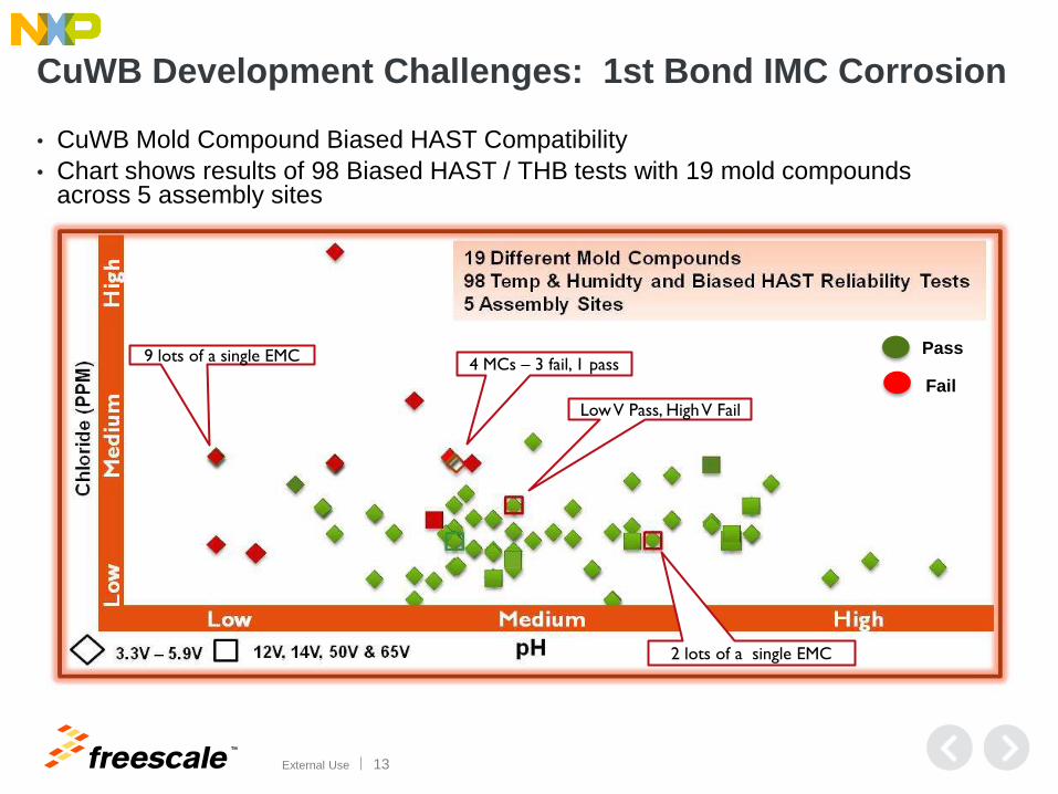
4 MCs – 3 fail, 1 pass
Low V Pass, High V Fail
9 lots of a single EMC
2 lots of a single EMC
Fail
Pass
CuWB Development Challenges: 1st Bond IMC Corrosion
• CuWB Mold Compound Biased HAST Compatibility
• Chart shows results of 98 Biased HAST / THB tests with 19 mold compounds across 5 assembly sites

TM
External Use 14
CuWB Development Challenges: 1st Bond IMC Corrosion
Challenge: Pass Biased HAST with both bare Cu and PdCu wire
Initially, corrosion
crack formed under
bare Cu ball bond
with biased HAST
Bare Cu
ball bond
Oxidized Al layer
Al
Cu Proper mold
compound and bond
optimization
eliminated failure
with Bare Cu
Pd-Cu
ball
bond
Corrosion layer
No corrosion
layer
Same BOM, after wire bond
optimization - No bHAST failure
Pd-Cu ball bond Corrosion crack
formed under
PdCu ball bond
with biased
HAST with MC
approved for
bare CuWB
FSL is successful in bHAST with both bare Cu, and PdCu wire

TM
External Use 15
CuWB Development Challenges: Lead Frame 2nd Bond
Issues Initial Optimized Risk / Specification / Action
2nd Bond
Lead frame
Design
• Spec: Zero heel crack
• Action: Optimize lead frame – no
change to wire looping or length
2nd Bond
Optimization on
LQFP (Ag-spot)
• Spec: Ag thickness – min and max range has been evaluated
• Action: Standard Ag thickness
Cu wire
Ag
Cu leadframe
Fishtail bond
Challenge: Achieve optimal 2nd bond without delamination or broken heel
• Cu work-hardens much more than Au – Effective ductility reduction in 2nd bond region
• 2nd bond optimization + Lead frame design optimization mitigates risk
TM
External Use 16
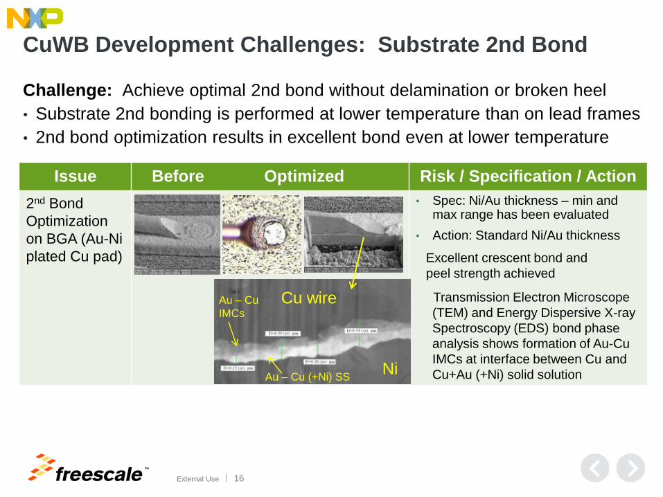
Issue Before Optimized Risk / Specification / Action
2nd Bond
Optimization
on BGA (Au-Ni
plated Cu pad)
• Spec: Ni/Au thickness – min and max range has been evaluated
• Action: Standard Ni/Au thickness
Transmission Electron Microscope
(TEM) and Energy Dispersive X-ray
Spectroscopy (EDS) bond phase
analysis shows formation of Au-Cu
IMCs at interface between Cu and
Cu+Au (+Ni) solid solution
Cu wire
Ni
Au – Cu
IMCs
Au – Cu (+Ni) SS
CuWB Development Challenges: Substrate 2nd Bond
Excellent crescent bond and
peel strength achieved
Challenge: Achieve optimal 2nd bond without delamination or broken heel
• Substrate 2nd bonding is performed at lower temperature than on lead frames
• 2nd bond optimization results in excellent bond even at lower temperature
TM
External Use 17
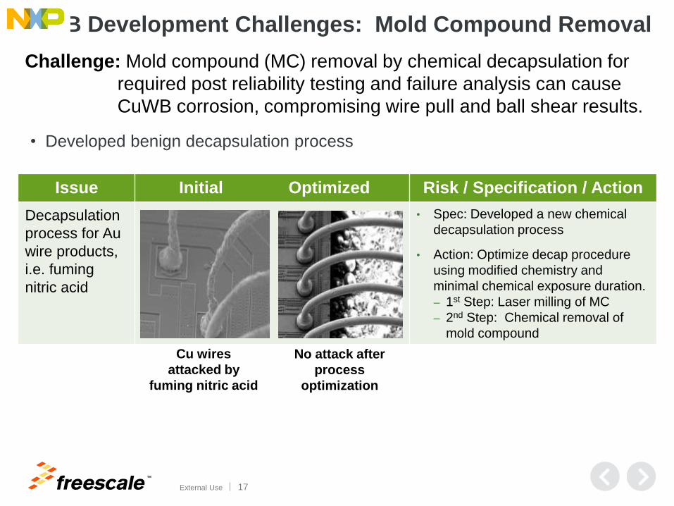
Issue Initial Optimized Risk / Specification / Action
Decapsulation
process for Au
wire products,
i.e. fuming
nitric acid
• Spec: Developed a new chemical
decapsulation process
• Action: Optimize decap procedure
using modified chemistry and
minimal chemical exposure duration.
‒ 1st Step: Laser milling of MC
‒ 2nd Step: Chemical removal of
mold compound
Challenge: Mold compound (MC) removal by chemical decapsulation for
required post reliability testing and failure analysis can cause
CuWB corrosion, compromising wire pull and ball shear results.
CuWB Development Challenges: Mold Compound Removal
Cu wires
attacked by
fuming nitric acid
No attack after
process
optimization
• Developed benign decapsulation process

TM
External Use 18
CuWB Development Challenges: Wire Type Verification
Gold Wire Copper Wire
Challenge: Determination of Cu or Au wire bonding in a package independent of Freescale date codes and lot traceability
• X-Ray may be used to determine the wire type
• May require use of a known Au or Cu unit for gray-scale comparison
• Au wires are darker in X-Ray images ( > X-ray attenuation)
• Example of same device with Au (left) and Cu (right) wires in X-Ray photo taken at same kV and current:

TM
External Use 19
CuWB Development Challenges: Cu Wire Bond Testing
Challenge: CuWB quality testing where failure modes differ vs. AuWB
• Cu wire is stronger than Au wire and Cu wire stretches before breaking
• Wire stretching increases torsion on bond interface
• Torsion may cause pad peel for high strength wire pulls.
Break at hook location
after wire stretch + bend
Wire neck region
High wire strength and
torque on strong IMC
bond can exceed strength
of ILD stack, causing pad
peeling, or ILD cracking
Lower
Torque Higher
Torque
Wire Pull Test

TM
External Use 20
CuWB Development Challenges: Cu Wire Bond Testing , cont.
• Cu wire bond to Al pad is stronger than Au bond to Al pad
• High bond strength results in different failure modes in high strength bonds
• Cu wire pull and ball shear meets Cpk ≥ 1.67. Variability is > Au wire.
Normal Au wire ball
shear mode: Shears
through Au above the
Au-Al IMC, leaving Au
on the pad.
Normal ball shear
mode for Cu wires.
Shears through the Al
layer, below the very
strong Cu-Al IMC,
leaving no Cu on the
pad.
Ball Shear Test

TM
External Use 21
Agenda
• What is Wire Bonding?
• Strategy and Background
• Key Development Challenges and Results
• Assembly Optimization for High Volume Mfg
• Sample Reliability Data and Electrical Performance
• FSL Cu Wire Products in Production
• Summary

TM
External Use 22
Process Name/
Operation
Description
Potential Failure
ModeProcess
Product/ Process
Specification
/Tolerance
Evaluation
Measurement
Technique
Sample Size Exit Criteria
Wire Bond Poor Ballbond Integrity Ball ShearMin 6.4g
(t0)
Ball shear Test
(t0)
1 strips/lot,
2 units/strip,
8 balls/unit.
Zero Fails, no
degradation trend
Cpk>1.67
Wire Bond Poor Ballbond Integrity Wire PullMin 4.5g
(t0)Wire Pull Test (t0)
1 strips/lot,
2 units/strip,
8 balls/unit.
Zero Fails, no
degradation trend
Cpk>1.67
Wire BondPoor Wedgebond
IntegrityWire Peel Min 2.5g (t0) Wire Peel Test (t0)
1 strips/lot,
2 units/strip,
8 balls/unit.
Zero Fails, no
degradation trend
Wire Bond Bond pad crateringCratering
TestNo cratering (t0) Cratering Test
1 strips/lot,
2 units/strip,
8 balls/unit.
Zero Fails, no
degradation trend
Wire Bond Poor Ballbond PlacementWirebond
PlacementWithin BPO
Visual Inspection
(min 10x)
1 strips/lot,
2 units/strip
Zero Fails, no
degradation trend
Wire Bond Poor Ballbond Placement Al Push Out Within BPOVisual Inspection
(min 10x)
1 strips/lot,
2 units/strip
Zero Fails, no
degradation trend
Wire Bond WB Yield WB Yield Per Yield ModelVisual Inspection
(min 10x)all units
No yield degradation
trend compare to
yield target (98.5%)
Mold Wire Sw eep Wire Sw eepMax 10% w ire
sw eepXray 10units/lot
Zero Fails, no
degradation trend
Mold Reliability
Mold
Compound
PH and Cl
PH: 5.2-6.5
Cl: 15ppm maxCoC every lot
Zero Fails, no
degradation trend
pH and Cl-
spec
Cu Wire Product Safe Launch Monitor Example 1st 30 production assembly lots (Examples for specific Cu wire, package, etc.)
TM
External Use 23
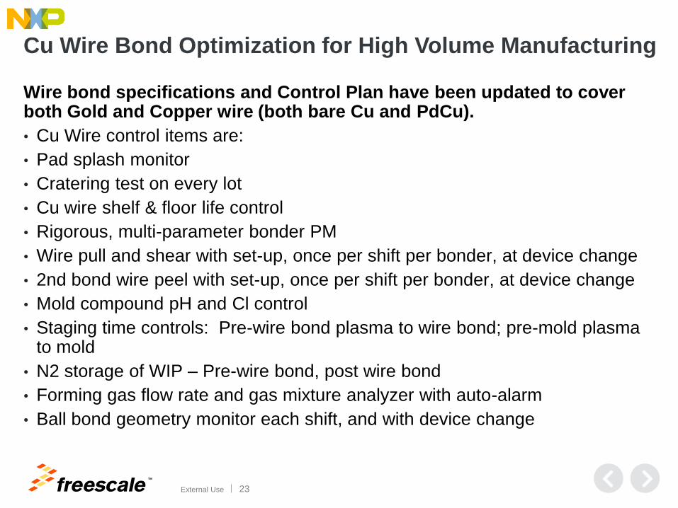
Cu Wire Bond Optimization for High Volume Manufacturing
Wire bond specifications and Control Plan have been updated to cover both Gold and Copper wire (both bare Cu and PdCu).
• Cu Wire control items are:
• Pad splash monitor
• Cratering test on every lot
• Cu wire shelf & floor life control
• Rigorous, multi-parameter bonder PM
• Wire pull and shear with set-up, once per shift per bonder, at device change
• 2nd bond wire peel with set-up, once per shift per bonder, at device change
• Mold compound pH and Cl control
• Staging time controls: Pre-wire bond plasma to wire bond; pre-mold plasma to mold
• N2 storage of WIP – Pre-wire bond, post wire bond
• Forming gas flow rate and gas mixture analyzer with auto-alarm
• Ball bond geometry monitor each shift, and with device change
TM
External Use 24
Agenda
• Strategy and Background
• Key Development Challenges and Results
• Assembly Optimization for High Volume Mfg
• Sample Reliability Data and Electrical Performance
• FSL Cu Wire Products in Production
• Summary

TM
External Use 25
Stress Conditions/Requirements TJN Results
64 LQFP Grouper
KLM Results
100 LQFP Grouper
WBS Wire Bond Shear (Avg min 17g / ind. min
9.5g), 30 bonds from 5 units per lot, 3 lots
Passed, Total 15 units
3 lots Cpk > 1.67
Passed, Total 15 units
3 lots Cpk > 1.67
WBP Wire Bond Pull (min 3g)
30 bonds from 5 units per lot, 3 lots
Passed, Total 15 units
3 lots Cpk > 1.67
Passed, Total 15 units
3 lots Cpk > 1.67
Stress Conditions/Requirements TJN Results
64 LQFP Grouper
KLM Results
100 LQFP Grouper
bHAST Preconditioning before biased Highly Accelerated
Stress Test:
bHAST = 130°C/85%RH for 96 hrs
Passed 2x reqt
192 hrs
3 lots 0/231
Passed 2x reqt
192 hrs
3 lots 0/231
uHAST Preconditioning before unbiased Highly
Accelerated Stress Test:
uHAST = 130°C/85%RH for 96 hrs
Passed 2x reqt
192 hrs
3 lots 0/231
Passed 2x reqt
192 hrs
3 lots 0/231
TC Preconditioning before Temperature Cycle: TC = -
65°C to 150°C for 500 cycles
WBP after TC on 5 units per lot, 3 lots
Minimum 3g force
Passed 4x reqt
2000 cycles
TC - 3 lots 0/231
WBP Cpk > 1.67
Passed 4x reqt
2000 cycles
TC - 3 lots 0/231
WBP Cpk > 1.67
HTSL High Temperature Storage Life:150°C for 1008 hrs Passed 2x reqt
2016 hrs
3 lots 0/231
Passed 2x reqt
2016 hrs
3 lots 0/231
Test Group C – Package Assembly Integrity Tests
0.18um S12G Product Family Extended Reliability Results Meet or exceed AEC1 requirements
Test Group A – Accelerated Environment Stress Tests

TM
External Use 26
Cu Wire High Temperature Application: High Temp Bake
• C90TFS Technology with Bond Over Active Pads – MAPBGA, 23µm bare Cu wire, Freescale TJN assembly site
Exceeds AEC grade 0 for HTB (150C for 2016 hr, or 175C for 1008 hr)
TM
External Use 27
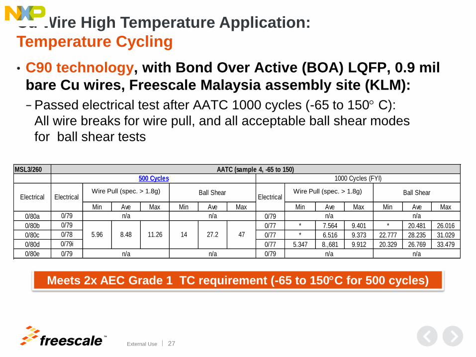
Meets 2x AEC Grade 1 TC requirement (-65 to 150C for 500 cycles)
MSL3/260
Min Ave Max Min Ave Max Min Ave Max Min Ave Max
0/80a 0/79
0/80b 0/77 * 7.564 9.401 * 20.481 26.016
0/80c 0/77 * 6.516 9.373 22.777 28.235 31.029
0/80d 0/77 5.347 8.,681 9.912 20.329 26.769 33.479
0/80e 0/79
0/79
0/79
0/78
0/79i
0/79
n/an/a
5.96 8.48 11.26 14 27.2
n/a
47
n/a
500 Cycles
Electrical Electrical ElectricalWire Pull Ball Shear
AATC (sample 4, -65 to 150)
n/a
n/a
n/a
n/a
Wire Pull (122393) Ball Shear
1000 Cycles (FYI)
Wire Pull (spec. > 1.8g) Wire Pull (spec. > 1.8g)
Cu Wire High Temperature Application:
Temperature Cycling
• C90 technology, with Bond Over Active (BOA) LQFP, 0.9 mil
bare Cu wires, Freescale Malaysia assembly site (KLM):
− Passed electrical test after AATC 1000 cycles (-65 to 150 C):
All wire breaks for wire pull, and all acceptable ball shear modes
for ball shear tests
TM
External Use 28
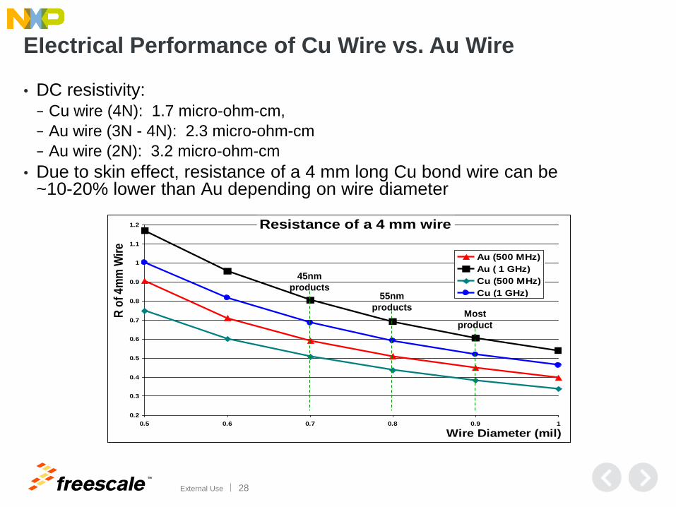
Electrical Performance of Cu Wire vs. Au Wire
0.2
0.3
0.4
0.5
0.6
0.7
0.8
0.9
1
1.1
1.2
0.5 0.6 0.7 0.8 0.9 1
Wire Diameter (mil)
R o
f 4
mm
Wir
e
Au (500 MHz)
Au ( 1 GHz)
Cu (500 MHz)
Cu (1 GHz)
Resistance of a 4 mm wire
Most
product
s
55nm
products
45nm
products
• DC resistivity: − Cu wire (4N): 1.7 micro-ohm-cm,
− Au wire (3N - 4N): 2.3 micro-ohm-cm
− Au wire (2N): 3.2 micro-ohm-cm
• Due to skin effect, resistance of a 4 mm long Cu bond wire can be ~10-20% lower than Au depending on wire diameter
TM
External Use 29
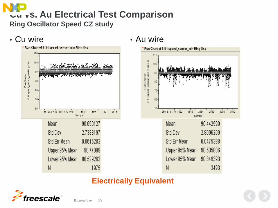
Cu vs. Au Electrical Test Comparison Ring Oscillator Speed CZ study
• Cu wire • Au wire
Electrically Equivalent
TM
External Use 30
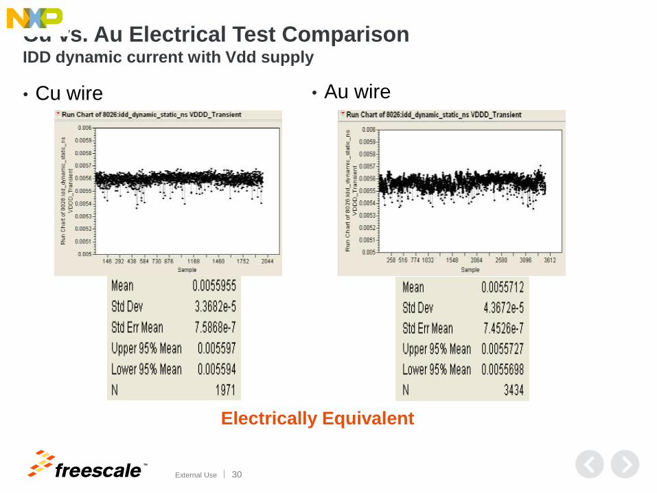
Cu vs. Au Electrical Test Comparison IDD dynamic current with Vdd supply
• Cu wire • Au wire
Electrically Equivalent

TM
External Use 31
Cu Wire Bond Improves High Temperature Reliability
(a) Cu-Al (b) Au-Al
Wire bonds after 2016 hrs at 150C (a) Cu-Al (b) Au-Al
Wire bonds after 0 hrs of Aging
Comparison of Cu and Au wire bonded to
an Al pad after aging.
• Cu-Al intermetallic has grown, but has
not completely consumed the Al pad.
No Kirkendall voiding is seen.
• Au-Al intermetallic has grown to
consume the entire thickness of the Al
pad, and large voids have formed in the
IMC region.
Comparison of Cu and Au wire bonded to an
Al pad with no aging.
• Very thin Cu-Al IMC layer vs. thick Au-Al
IMC layer with early Kirkendall voiding
Voids

TM
External Use 32
Cu Wire Bond Improves High Temperature Reliability
• Here, the IMC growth rate is approximated to inversely correlate with reliability
• 175 C 1000 hr: Bare Cu Wire - Cu-Al IMC growth rate is ~1/10 the Au-Al rate
− Reliability of Cu-Al bond is 10X that of Au-Al bond 175 C
• Freescale work: 150 C 1000 hr: PdCu Wire - Cu-Al IMC growth rate ~1/38 the rate of Au-Al IMC
− Reliability of PdCu-Al bond is 38X that of Au-Al bond at 150 C
100 hrs.
500 hrs.
1000 hrs.
1600 hrs.
Calculated ball bond IMC thickness vs.
Square root of time at 175C
ref. C. Breach, The Great Debate: Copper vs. Gold Ball Bonding,
Advanced Packaging, Oct. 2008. (Calculated from data from H. J.
Kim, et al., IEEE Transactions on Components and Packaging
Technologies, Vol. 26, No. 2, June 2003).
IMC Diffusion Coefficient
(D; cm2/sec) from Freescale Studies
Wire Type on Al Pad Temp(150C)
Au - Al 1.10 X 10⁻¹⁴
PdCu - Al 2.89 X 10⁻¹⁶
(Au-Al IMC growth 38x faster vs. PdCu
wire; ~10x faster vs. bare Cu wire)

TM
External Use 33
Cu Wire Bond Improves High Temperature Reliability
• Freescale Cu-Al IMC Bond Interface Studies (PdCu Wire) up to
225 C to determine IMC growth activation energy
200C - 288 hrs
PdCu Ball
IMC growth with no voids

TM
External Use 34
Agenda
• Strategy and Background
• Key Development Challenges and Results
• Assembly Optimization for High Volume Mfg
• Sample Reliability Data and Electrical Performance
• FSL Cu Wire Products in Production
• Summary
TM
External Use 35
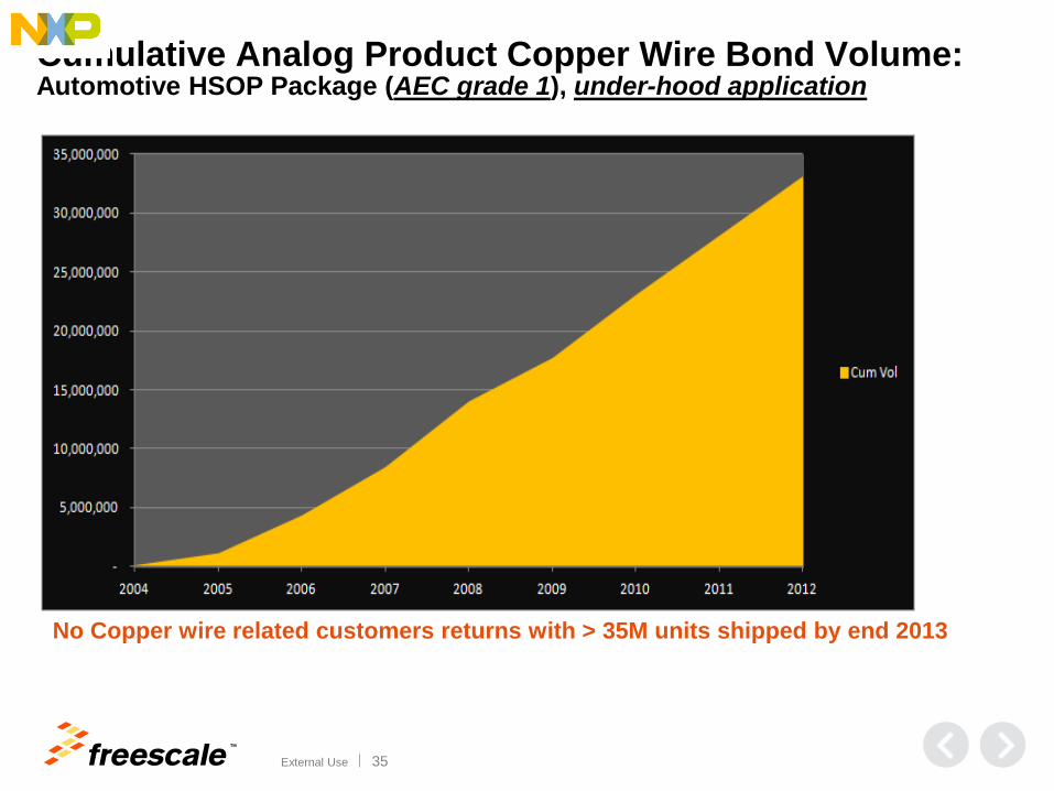
Cumulative Analog Product Copper Wire Bond Volume: Automotive HSOP Package (AEC grade 1), under-hood application
No Copper wire related customers returns with > 35M units shipped by end 2013
TM
External Use 36
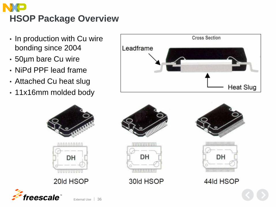
HSOP Package Overview
• In production with Cu wire
bonding since 2004
• 50µm bare Cu wire
• NiPd PPF lead frame
• Attached Cu heat slug
• 11x16mm molded body

TM
External Use 37
No Cu wire related customers returns with
> 300M units shipped by end December 2013
Cumulative Copper Wire Bond Volume by Package Type Consumer and Industrial Microcontroller & Digital Networking Products
TM
External Use 38
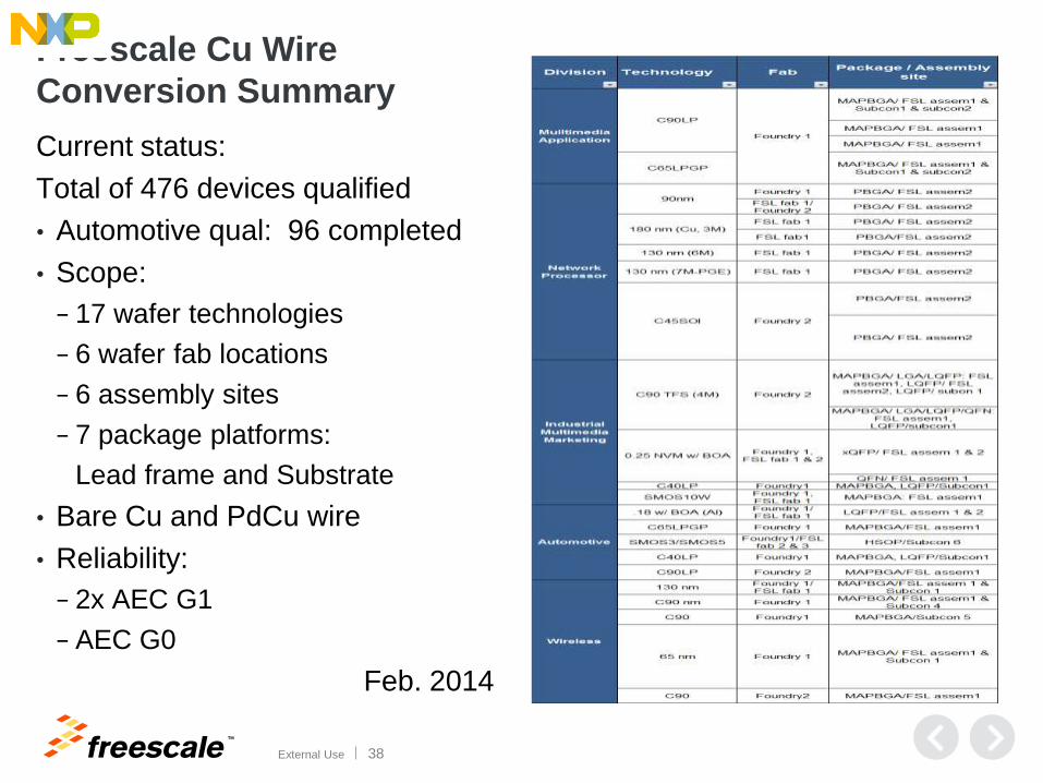
Freescale Cu Wire
Conversion Summary
Current status:
Total of 476 devices qualified
• Automotive qual: 96 completed
• Scope:
− 17 wafer technologies
− 6 wafer fab locations
− 6 assembly sites
− 7 package platforms:
Lead frame and Substrate
• Bare Cu and PdCu wire
• Reliability:
− 2x AEC G1
− AEC G0
Feb. 2014
TM
External Use 39
Agenda
• Strategy and Background
• FSL Cu Wire Strategy
• Development Methodology Flow
• Key Development Challenges and Results
• Assembly Optimization for High Volume Mfg
• Sample Reliability Data and Electrical Performance
• FSL Cu Wire Products in Production
• Summary

TM
External Use 40
Cu Bond Wire Summary
• Gold (Au) and Copper (Cu) wire have been used in ICs for the interconnection of silicon die to package terminals for many years.
• FSL has shipped > 60M automotive analog components from 2004, to date with no customer issues
• Recent wire bond technology advancements are expanding the use of Cu wire.
• FSL has converted Consumer / Industrial microcontrollers to Cu wire and now initiating Automotive conversions.
− > 230M units shipped to date with no customer issues
Motivation
• Some new products require a high temperature application in which Cu wire is the best solution.
• Avoids the need to pass on increased Au wire costs.
Introduction / Change Strategy • All new products will be introduced with Cu wire
• All Fab expansion products will be qualified with Cu wire
• Existing product families will migrate to Cu wire
− Note: Some legacy products will migrate to thinner Au wire

TM
© 2014 Freescale Semiconductor, Inc. | External Use
www.Freescale.com