tutorial 1.docx
TRANSCRIPT

Tuesday, December 2, 2008
LED 7-Segment Multiplexing
In my first Digital Clock, I use 6 pcs. of CD4543,BCD to 7-Segment decoder, to drive 6 digit LED 7-Segment display for the sake of simplicity of the software. However, the hardware needs many components. As you can see in the post, the PCB of the clock is quite big and containing a
lot of solder points. To reduce the number of components, I will integrate the function of CD4543 into the firmware. One digit requires 7 connections (wires) for all segments and 1 connection for common cathode (or anode). If I connect 6 digits to the MCU without any
modification, I will need 7-segment x 6 digit = 42 connections . That means I need to use MCU with atleast 42 I/O pins. As you know, it is a waste for using a lot of MCU pins just for display.
The required pins can be reduced dramatically by using a technique called Multiplexing.
Multiplexing
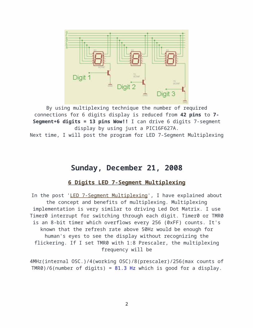
Multiplexing technique is based on the idea of Persistence of vision of the human eyes. The sample schematic of 3 digits multiplexing is shown below. Segment a-g of each digit are
connected together. Each digit is switched on-off by controlling signal at Digit 1, Digit 2 and Digit 3. For example, if Digit 1 is '1' , Digit 1 will be on. If Digit 1 is '0', Digit 1 will be off.
People will see all 3 digits display in the same time if each digit switch on and off fast enough.
By using multiplexing technique the number of required connections for 6 digits display is reduced from 42 pins to 7-Segment+6 digits = 13 pins Wow!! I can drive 6 digits 7-segment
display by using just a PIC16F627A.Next time, I will post the program for LED 7-Segment Multiplexing
1
Sunday, December 21, 2008
6 Digits LED 7-Segment Multiplexing
In the post 'LED 7-Segment Multiplexing', I have explained about the concept and benefits of multiplexing. Multiplexing implementation is very similar to driving Led Dot Matrix. I use Timer0 interrupt for switching through each digit. Timer0 or TMR0 is an 8-bit timer which
overflows every 256 (0xFF) counts. It's known that the refresh rate above 50Hz would be enough for human's eyes to see the display without recognizing the flickering. If I set TMR0 with 1:8
Prescaler, the multiplexing frequency will be
4MHz(internal OSC.)/4(working OSC)/8(prescaler)/256(max counts of TMR0)/6(number of digits) = 81.3 Hz which is good for a display.
Just an example, I have implemented (in Proteus) a 999999-second counter by using 6 Digits LED 7-Segment Multiplexing technique. There are 2 main components in the
project, PIC16F627A or PIC16F628 and 6 x LED7-segment display. The schematic shows below. The crystal is 32.768KHz as usual. There is a 10KOhm pull up resistor at RA4 pin
as this pin is an open-drain pin as I described in "Open-Drain RA4 pin on PIC Microcontroller".
Wednesday, December 31, 2008
6 Digits 7-Segment LED Multiplexing using a Shift Register
Multiplexing technique can reduce number of needed I/O pins of the MCU as I have explained in 'LED 7-Segment Multiplexing' and '6 Digits LED 7-Segment Multiplexing'. In those posts, I
used 13 I/O pins for driving 6 digits LED 7-Segment. However, the PIC16F627A and PIC16F628 have only 15 usable I/O pins that include 2 pins for external 32.768KHz oscillator. So, there is no pin left for time setting buttons. I can change to the PIC that has more I/O pins, but I don't think it's a good solution. From my searches, I can overcome this I/O pins shortage
problem by using shift register to expand the MCU I/O pins.
The concept is very similar to led dot matrix driving technique. Each digit is multiplexed via a shift register 74HC595 which is required 3 pins of the MCU. Each segment of the 7-segment
display is driven by PORTA of the PIC16F628. As a result, the required pins for driving 6-Digit 7-Segment display are just 3+7 = 10 pins!. With this configuration, there are 3 I/O pins that are
2

free for time setting buttons and driving blinking second LEDs.
I use TMR2 module for scanning digits. TMR2 is an 8-bit timer which overflows every 256 (0xFF) counts. It's known that the refresh rate above 50Hz would be enough for human's eyes to see the display without recognizing the flickering. If I set TMR2 with 1:8 Prescaler (T2CON = 0x3C), the multiplexing frequency will be 81.3Hz (4MHz/4/256/8/6 = 81.3Hz) which is enough
for flicker free display.
PORTA is used to drive each segment of the 7-segment displays. However, I have to skip the RA5 as it's a MCLR pin and it can be only input pin. So, my 7-segment digit mask is different
then the normal 7-segment digit mask.
my PORTA 7-segment digit mask : {0x5F, 0x06, 0x9b, 0x8f, 0xC6, 0xCd,0xDD, 0x07,0xDf, 0xCf}
Normal 7-segment digit mask : {0x3f, 0x06, 0x5b, 0x4f, 0x66, 0x6d, 0x7d, 0x07, 0x7f, 0x6f} for number 0-9 respectively.
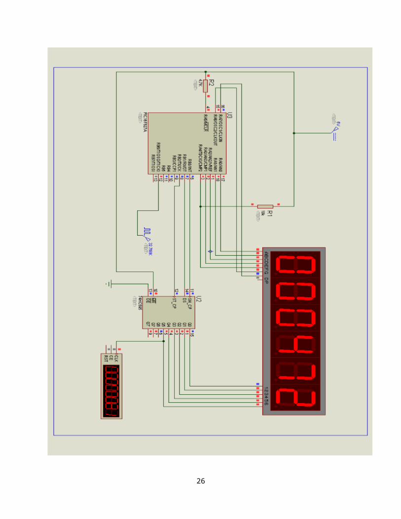
Below is the example schematic of 999999-second counter using the PIC16F627A or PIC16F628 and a shift register. I will not implement a clock with this configuration as I need more free
MCU pins for driving Alarm buzzer and other things.
3

The source code in MikroC is listed below: (.hex is also available, please feel free to contact me)//PIC16F627A//4MHz Internal OSC//MUX by the MUC itself with Interrupt//TMR0 .. check the prescelar+delay in scan routine as they are related//[email protected] short number [10] = { 0x5F, 0x06, 0x9b, 0x8f, 0xC6, 0xCd, 0xDD, 0x07, 0xDf, 0xCf};unsigned short digit [6];unsigned short counter;unsigned short shift_register;unsigned short x1;unsigned short x2;unsigned short x3;unsigned short x4;
4

unsigned short x5;unsigned short x6;unsigned short tick;void interrupt (){ if (INTCON.T0IF) { //Scan digits with TMR0 INTCON.T0IF = 0; if (counter == 5) { PORTA = number [digit [counter]]; Delay_us (500); shift_register = 0x01; PORTB = ~shift_register; PORTA = 0x00; counter = 0; } else { PORTA = number [digit [counter]]; Delay_us (500); shift_register = shift_register << 1; PORTB = ~shift_register; PORTA = 0x00; counter ++; } } if (PIR1.TMR1IF) { TMR1H = 0x80; PIR1.TMR1IF = 0; tick = 1; //update current time x6 ++; if (x6 > 9) { x6 = 0; x5 ++; if (x5 > 9) { x5 = 0;
5

x4 ++; if (x4 > 9) { x4 = 0; x3 ++; if (x3 > 9) { x3 = 0; x2 ++; if (x2 > 9) { x2 = 0; x1 ++; if (x1 > 9) { x1 = 0; } } } } } } }}void main (){ //Digital I/O for PORTA CMCON = 0x07; TRISA = 0x00; PORTA = 0x00; TRISB = 0x00; PORTB = 0x00; //Internal Clock 4MHz PCON.OSCF = 1; counter = 0; // Enable TMR0 OPTION_REG.T0CS = 0; // Enable Prescaler OPTION_REG.PSA = 0; // PS0,1,2 = 010 = 3 // 3 means 1:8 prescaler
6

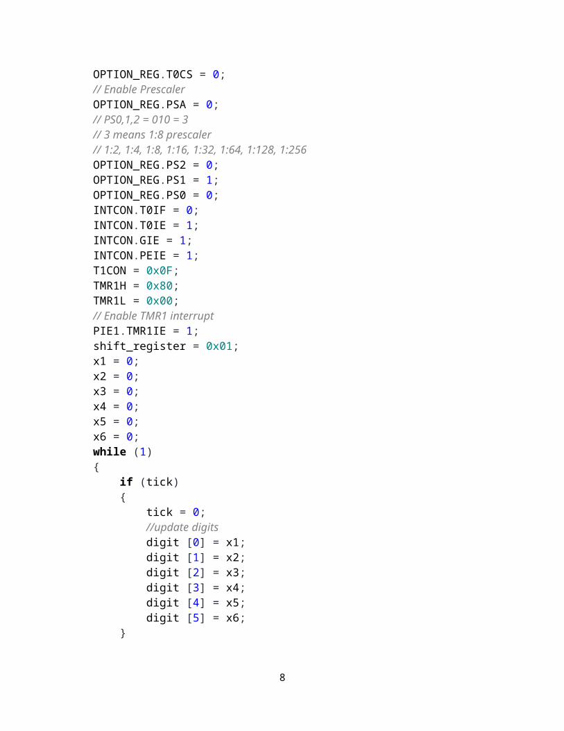
// 1:2, 1:4, 1:8, 1:16, 1:32, 1:64, 1:128, 1:256 OPTION_REG.PS2 = 0; OPTION_REG.PS1 = 1; OPTION_REG.PS0 = 0; INTCON.T0IF = 0; INTCON.T0IE = 1; INTCON.GIE = 1; INTCON.PEIE = 1; T1CON = 0x0F; TMR1H = 0x80; TMR1L = 0x00; // Enable TMR1 interrupt PIE1.TMR1IE = 1; shift_register = 0x01; x1 = 0; x2 = 0; x3 = 0; x4 = 0; x5 = 0; x6 = 0; while (1) { if (tick) { tick = 0; //update digits digit [0] = x1; digit [1] = x2; digit [2] = x3; digit [3] = x4; digit [4] = x5; digit [5] = x6; } }}
Tuesday, August 4, 2009
Small LED dot matrix development board
7
I was very busy for the past two months so this blog just didn't move. As you may know, the LED dot matrix display is my favorite device. I have designed a small development board for
testing my led dot matrix related programs.The schematic is as the following:
8

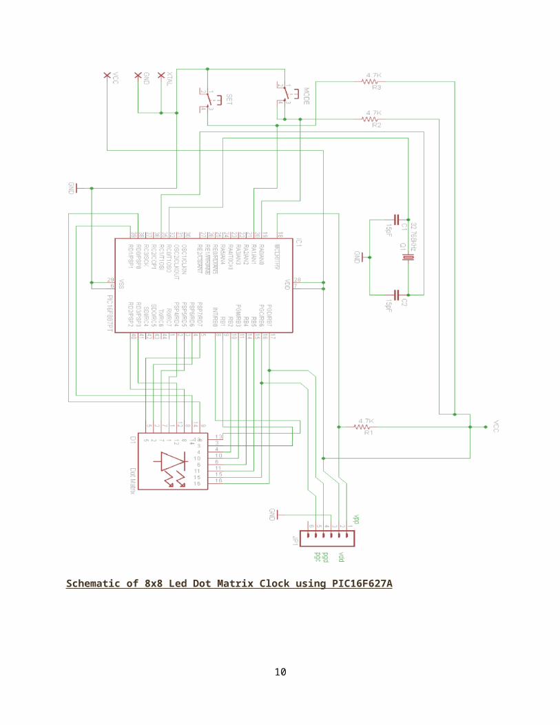
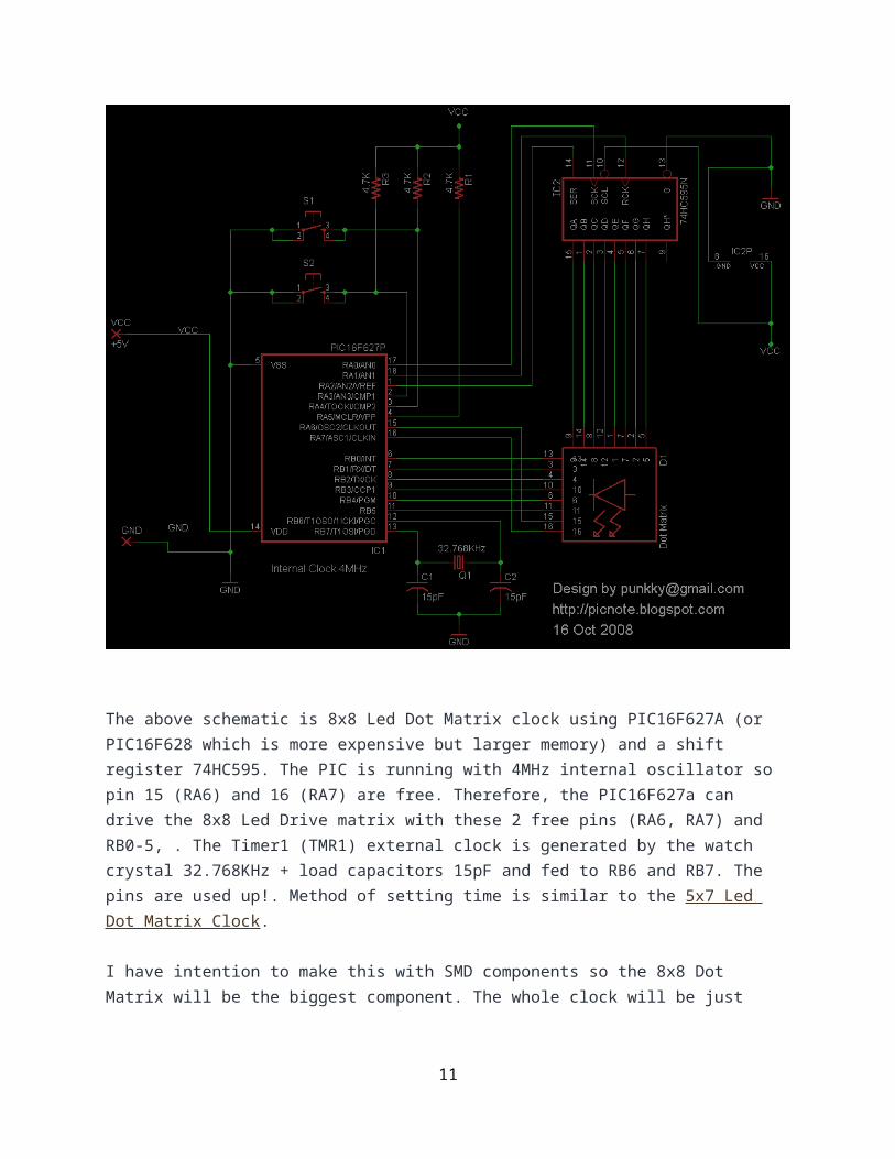
Schematic of 8x8 Led Dot Matrix Clock using PIC16F627A
The above schematic is 8x8 Led Dot Matrix clock using PIC16F627A (or PIC16F628 which is more expensive but larger memory) and a shift register 74HC595. The PIC is running with 4MHz internal oscillator so pin 15 (RA6) and 16 (RA7) are free. Therefore, the PIC16F627a can drive the 8x8 Led Drive matrix with these 2 free pins (RA6, RA7) and RB0-5, . The Timer1 (TMR1) external clock is generated by the watch crystal 32.768KHz + load capacitors 15pF and fed to RB6 and RB7. The pins are used up!. Method of setting time is similar to the 5x7 Led Dot Matrix Clock.
I have intention to make this with SMD components so the 8x8 Dot Matrix will be the biggest component. The whole clock will be just 20x20mm which is small enough to be a small pocket watch or even a wristwatch. The only problem is the power supply.
9
Saturday, October 11, 2008
8x8 Led Dot Matrix Clock using PIC16F627A
Actually, I have made this long before the 5x7 led dot matrix clock. The clock utilizes a PIC16F627A and a 74HC595 to drive a small 8x8 Led Dot Matrix display (20x20mm). My dream is transforming these clocks to watches that I can ware on
my wrist.
Posted by punkky at Saturday, October 11, 2008 9 comments Topics: Clock, Dot Matrix, PIC16F627a, PIC16F628
Monday, October 6, 2008
Big 5x7 Led Dot Matrix Clock with new font
Now, I'm so crazy about led dot matrix clocks and led dot matrix watches. Just recently, I have upgraded my small 5x7 Led Dot Matrix Clock with a bigger green 5x7 led dot matrix display
and a new font.
10
For the images below, the time 21:44:37 was displaying on the clock. The clock display is big comparing to a 44mm Panerai (PAM 4).
11

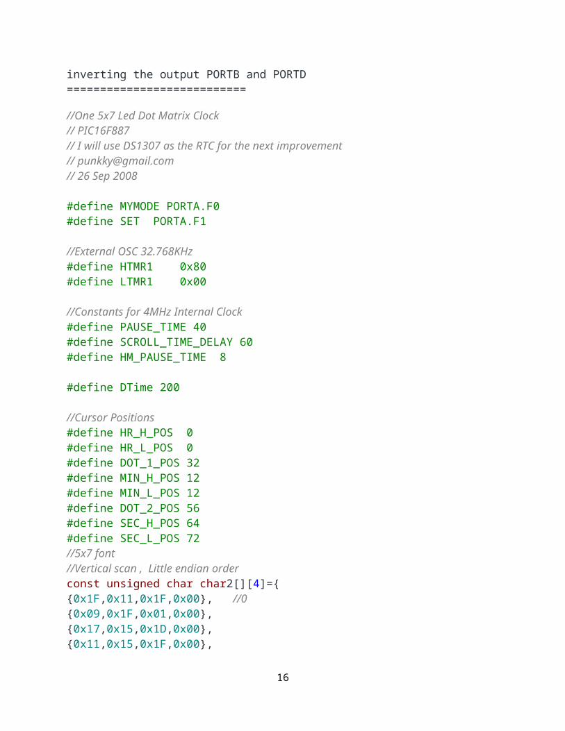
The code for the new font is showing below:
const unsigned char char2[][4]={{0x0E,0x11,0x0E,0x00}, //0{0x09,0x1F,0x01,0x00}, //1{0x13,0x15,0x09,0x00}, //2{0x11,0x15,0x0A,0x00}, //3{0x1C,0x04,0x0F,0x00}, //4{0x19,0x15,0x12,0x00}, //5{0x0E,0x15,0x12,0x00}, //6{0x13,0x14,0x18,0x00}, //7{0x0A,0x15,0x0A,0x00}, //8{0x09,0x15,0x0E,0x00}, //9{0x0A,0x04,0x0A,0x00}, //Comma1{0x04,0x0A,0x04,0x00} //Comma2};
Friday, September 26, 2008
Source Code for one chip 5x7 led dot matrix clock
As promised, listed below is the source code in MikroC for the 5x7 Led Dot Matrix Clock. The free demo version of MikroC can compile this code without any problem. Of course, the code is just for educational purpose only and use it with your own risk. The explanation about the source code will come later. Setting time- Press and hold MODE button until the digits blink - The blinking digits are the hour is being set- Press SET button to count up the hour- When get the right hour, press MODE button to confirm hour setting - Now the minute digits are blinking and ready to be set- Press SET button to count up the minute- When get the right minute, press MODE button to confirm minute setting and the second will be set to 0 automatically- Now, the clock is set and the clock is running
Have fun!!!
Next improvements:
12

1. Using DS1307 as the time base will improve the clock accuracy and backup battery is also a nice feature of the DS13072. Dot matrix will be scanned and updated via interrupt routine to give the PIC more free time for doing something else
== Updated on 29 Nov 2009 ===This firmware is written for The 5x7 Dot matrix Cathode Row. If you use Anode Row you have to make change to make_dotmatrix() by inverting the output PORTB and PORTD===========================
//One 5x7 Led Dot Matrix Clock// PIC16F887// I will use DS1307 as the RTC for the next improvement// [email protected]// 26 Sep 2008
#define MYMODE PORTA.F0#define SET PORTA.F1
//External OSC 32.768KHz#define HTMR1 0x80#define LTMR1 0x00
//Constants for 4MHz Internal Clock #define PAUSE_TIME 40#define SCROLL_TIME_DELAY 60#define HM_PAUSE_TIME 8
#define DTime 200
//Cursor Positions#define HR_H_POS 0#define HR_L_POS 0#define DOT_1_POS 32#define MIN_H_POS 12#define MIN_L_POS 12#define DOT_2_POS 56#define SEC_H_POS 64#define SEC_L_POS 72//5x7 font//Vertical scan , Little endian order
13

const unsigned char char2[][4]={{0x1F,0x11,0x1F,0x00}, //0{0x09,0x1F,0x01,0x00},{0x17,0x15,0x1D,0x00},{0x11,0x15,0x1F,0x00},{0x1C,0x04,0x1F,0x00},{0x1D,0x15,0x17,0x00},{0x1F,0x15,0x17,0x00},{0x10,0x10,0x1F,0x00},{0x1F,0x15,0x1F,0x00},{0x1D,0x15,0x1F,0x00}, //9{0x0E,0x0E,0x0E,0x00}, //Comma1{0x04,0x0E,0x04,0x00} //Comma2};
unsigned char output[8];unsigned char data[40];unsigned char ptr;unsigned char base_ptr;unsigned char result_ptr;unsigned char pp;unsigned char pause_cnt;unsigned char hr_pause_cnt;unsigned char min_pause_cnt;unsigned short counter;unsigned short sec_h;unsigned short sec_l;unsigned short min_h;unsigned short min_l;unsigned short hr_h;unsigned short hr_l;unsigned short tick;unsigned short num;unsigned short i;unsigned short j;unsigned short time[8];unsigned short setting_time;unsigned short change_MYMODE;void check_bt();void button_fn(unsigned short param1, unsigned short pos1, unsigned short pos2);
14

void make_dotmatrix();
void interrupt() { //Internal clock PIR1.TMR1IF = 0; // clears TMR1IF TMR1H = HTMR1; //Set only high byte tick = 1; // increment counter}void update_time();void make_time();void fill_data();void show_digit(unsigned short pos);void scroll();void pause_digit(unsigned short position,unsigned short pause_delay);
unsigned short shift_register;void main(){ setting_time = 0; change_MYMODE = 0; ANSEL = 0x00; //Digital I/O for PORTA TRISA = 0x03; PORTA = 0x03; TRISB = 0x00; PORTB = 0xFF; TRISC = 0x0E; TRISD = 0x00; PORTD = 0x00; ANSELH = 0x00; //Digital Input for PORTB
OSCCON = 0x65 ; //pic16f887 : 0110 0101, Internal Osc at 4MHz for lowest power consumption
counter = 0; shift_register = 0x01; hr_h = 1; hr_l = 2; min_h = 3; min_l =4; sec_h = 0; sec_l = 0; tick = 0;
15
fill_data(); pause_cnt =0; hr_pause_cnt = 0; min_pause_cnt = 0;//TMR1 setup T1CON = 0x8F; // 887 TMR1 Prescaler 1:1 external clock INTCON = 0xC0; // Set GIE, PEIE TMR1H = 0x80; TMR1L = 0x00; Delay_ms(10); // Delay for setting up TMR1 PIE1.TMR1IE = 1; // enable interupt tick =0; while(1){ scroll(); }
}
void show_digit(unsigned short pos){ for(i=0;i<8;i++){ output[i] = data[i+pos]; }}
void update_time(){ if(tick){ tick =0; sec_l++; make_time(); fill_data(); }}
void make_time(){ if(sec_l>9){ sec_l = 0; sec_h++; } if(sec_h>5){ sec_h=0;
16

min_l++; } if(min_l>9){ min_l = 0; if(setting_time == 0){ min_h++; } } if(min_h>5){ min_h = 0; if(setting_time == 0){ hr_l++; } } if(hr_l>9){ hr_l = 0; if(setting_time == 0){ hr_h++; } } if(hr_h >2){ hr_h = 0; } if(hr_h >=2 && hr_l>3){ if(setting_time == 0){ hr_h = 0; } hr_l = 0; }
}void fill_data(){ time[0] = hr_h; time[1] = hr_l; time[2] = 10; time[3] = min_h; time[4] = min_l; time[5] = 11; time[6] = sec_h; time[7] = sec_l; for(i = 0;i<8;i++){
17

for(j=0;j<4;j++){ data[j+4*i] = char2[time[i]][j]; } }}
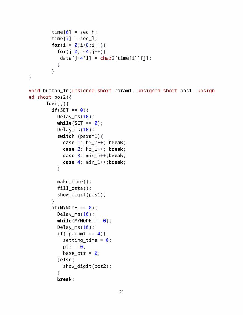
void button_fn(unsigned short param1, unsigned short pos1, unsigned short pos2){ for(;;){ if(SET == 0){ Delay_ms(10); while(SET == 0); Delay_ms(10); switch (param1){ case 1: hr_h++; break; case 2: hr_l++; break; case 3: min_h++;break; case 4: min_l++;break; }
make_time(); fill_data(); show_digit(pos1); } if(MYMODE == 0){ Delay_ms(10); while(MYMODE == 0); Delay_ms(10); if( param1 == 4){ setting_time = 0; ptr = 0; base_ptr = 0; }else{ show_digit(pos2); } break; } make_dotmatrix(); Delay_ms(1); }
18

}void check_bt(){ while(MYMODE == 0){ Delay_ms(10); for(i=0;i<100;i++){ for(j=0;j<10;j++){ make_dotmatrix(); Delay_ms(1); if(MYMODE != 0){ setting_time = 0; change_MYMODE = 1; break; } } }
while(MYMODE == 0){ // Set Hr high setting_time = 1; show_digit(HR_H_POS); make_dotmatrix(); } if(change_MYMODE){ ptr=8; base_ptr = 0; change_MYMODE = 0; } } if(setting_time){ INTCON.GIE = 0 ; //Stop time counting
button_fn(1, HR_H_POS, HR_L_POS); button_fn(2, HR_L_POS, MIN_H_POS); button_fn(3, MIN_H_POS, MIN_L_POS); button_fn(4, MIN_L_POS, 0);
//Reset timer1 TMR1L = LTMR1; TMR1H = HTMR1; INTCON.GIE = 1 ; // start clock sec_l =0; sec_h =0;
19

tick=0; make_time(); fill_data(); }}
void pause_digit(unsigned short position, unsigned short pause_delay){ if(base_ptr == position){ if(pause_cnt<pause_delay){ base_ptr--; pause_cnt++; }else{ base_ptr = position+1; pause_cnt=0; }
}
}void scroll(){ ptr = 0; //start pointer base_ptr = 0; while(base_ptr<41){ result_ptr = (base_ptr+ptr)%40; output[ptr] = data[result_ptr]; ptr++; if(ptr == 8){ ptr = 0; base_ptr++; //Sec pause pause_digit(25,PAUSE_TIME); //Min pause pause_digit(13,HM_PAUSE_TIME); //Hr pause pause_digit(1,HM_PAUSE_TIME);
20
} for(pp=0;pp<SCROLL_TIME_DELAY;pp++){ update_time(); make_dotmatrix(); }
update_time(); check_bt(); make_dotmatrix(); }}void make_dotmatrix(){ if(counter == 7){ PORTB = output[counter]; //sent font data to PORTB Delay_us(DTime); PORTB = 0x00; //Turn off dots shift_register = 0x01; PORTD = ~shift_register; //sent scan data to PORTD counter = 0; } else{ PORTB = output[counter]; Delay_us(DTime); PORTB = 0x00; //Turn off dots shift_register = shift_register << 1; PORTD = ~shift_register; counter++; }}
21

22

Wednesday, March 11, 2009
Setting Internal Oscillator for PIC16F627A
I love to use PIC16F627A and PIC16F628 because they come with internal oscillators. That means I can make a project with lower component count (without 1 crystal and 2 load
capacitors). The project setting of MikroC for using internal oscillator of the PIC16F627A shows below:
Wednesday, December 31, 2008
6 Digits 7-Segment LED Multiplexing using a Shift Register
Multiplexing technique can reduce number of needed I/O pins of the MCU as I have explained in 'LED 7-Segment Multiplexing' and '6 Digits LED 7-Segment Multiplexing'. In those posts, I
used 13 I/O pins for driving 6 digits LED 7-Segment. However, the PIC16F627A and PIC16F628 have only 15 usable I/O pins that include 2 pins for external 32.768KHz oscillator. So, there is no pin left for time setting buttons. I can change to the PIC that has more I/O pins, but I don't think it's a good solution. From my searches, I can overcome this I/O pins shortage
23

problem by using shift register to expand the MCU I/O pins.
The concept is very similar to led dot matrix driving technique. Each digit is multiplexed via a shift register 74HC595 which is required 3 pins of the MCU. Each segment of the 7-segment
display is driven by PORTA of the PIC16F628. As a result, the required pins for driving 6-Digit 7-Segment display are just 3+7 = 10 pins!. With this configuration, there are 3 I/O pins that are
free for time setting buttons and driving blinking second LEDs.
I use TMR2 module for scanning digits. TMR2 is an 8-bit timer which overflows every 256 (0xFF) counts. It's known that the refresh rate above 50Hz would be enough for human's eyes to see the display without recognizing the flickering. If I set TMR2 with 1:8 Prescaler (T2CON = 0x3C), the multiplexing frequency will be 81.3Hz (4MHz/4/256/8/6 = 81.3Hz) which is enough
for flicker free display.
PORTA is used to drive each segment of the 7-segment displays. However, I have to skip the RA5 as it's a MCLR pin and it can be only input pin. So, my 7-segment digit mask is different
then the normal 7-segment digit mask.
my PORTA 7-segment digit mask : {0x5F, 0x06, 0x9b, 0x8f, 0xC6, 0xCd,0xDD, 0x07,0xDf, 0xCf}
Normal 7-segment digit mask : {0x3f, 0x06, 0x5b, 0x4f, 0x66, 0x6d, 0x7d, 0x07, 0x7f, 0x6f} for number 0-9 respectively.
Below is the example schematic of 999999-second counter using the PIC16F627A or PIC16F628 and a shift register. I will not implement a clock with this configuration as I need more free
MCU pins for driving Alarm buzzer and other things.
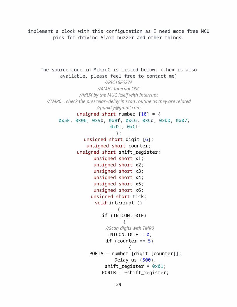
The source code in MikroC is listed below: (.hex is also available, please feel free to contact me)//PIC16F627A
//4MHz Internal OSC//MUX by the MUC itself with Interrupt
//TMR0 .. check the prescelar+delay in scan routine as they are related
//[email protected] short number [10] = {
0x5F, 0x06, 0x9b, 0x8f, 0xC6, 0xCd, 0xDD, 0x07, 0xDf, 0xCf
24

};unsigned short digit [6];unsigned short counter;
unsigned short shift_register;unsigned short x1;unsigned short x2;unsigned short x3;unsigned short x4;unsigned short x5;unsigned short x6;unsigned short tick;void interrupt ()
{ if (INTCON.T0IF)
{ //Scan digits with TMR0
INTCON.T0IF = 0; if (counter == 5)
{ PORTA = number [digit [counter]];
Delay_us (500); shift_register = 0x01; PORTB = ~shift_register;
PORTA = 0x00; counter = 0;
} else {
PORTA = number [digit [counter]]; Delay_us (500);
shift_register = shift_register << 1; PORTB = ~shift_register;
PORTA = 0x00; counter ++;
} }
if (PIR1.TMR1IF) {
TMR1H = 0x80; PIR1.TMR1IF = 0;
tick = 1; //update current time
25
x6 ++; if (x6 > 9)
{ x6 = 0; x5 ++;
if (x5 > 9) {
x5 = 0; x4 ++;
if (x4 > 9) {
x4 = 0; x3 ++;
if (x3 > 9) {
x3 = 0; x2 ++;
if (x2 > 9) {
x2 = 0; x1 ++;
if (x1 > 9) {
x1 = 0; }
} } } }
} }}
void main (){
//Digital I/O for PORTA CMCON = 0x07; TRISA = 0x00; PORTA = 0x00; TRISB = 0x00; PORTB = 0x00;
//Internal Clock 4MHz
26

PCON.OSCF = 1; counter = 0; // Enable TMR0
OPTION_REG.T0CS = 0; // Enable Prescaler OPTION_REG.PSA = 0; // PS0,1,2 = 010 = 3
// 3 means 1:8 prescaler // 1:2, 1:4, 1:8, 1:16, 1:32, 1:64, 1:128, 1:256
OPTION_REG.PS2 = 0; OPTION_REG.PS1 = 1; OPTION_REG.PS0 = 0; INTCON.T0IF = 0; INTCON.T0IE = 1; INTCON.GIE = 1; INTCON.PEIE = 1; T1CON = 0x0F; TMR1H = 0x80; TMR1L = 0x00;
// Enable TMR1 interrupt PIE1.TMR1IE = 1;
shift_register = 0x01; x1 = 0; x2 = 0; x3 = 0; x4 = 0; x5 = 0; x6 = 0;
while (1) {
if (tick) {
tick = 0; //update digits digit [0] = x1; digit [1] = x2; digit [2] = x3; digit [3] = x4; digit [4] = x5; digit [5] = x6;
}
27

}}
1. /*2. Trial1 displaying matrix3. */4.5. sbit clock_a at rc0_bit;6. sbit data_a at rc1_bit;7. sbit latch_a at rc2_bit;8.9. sbit clock_b at rd6_bit;10. sbit reset at rd7_bit;11. sbit enable at rd5_bit;12.13. const unsigned short arrays[][8] = {{0xFF,0xFF,0x80,0x77,0x77,0x77,0x80,0xFF}14. };15. unsigned int scanner, scanner2, scantime, disp, row, column, mask, repeat;16.
28
17. void main() {18. LATC = 0x00;19. CMCON = 0x07; 20. ADCON0 = 0x00;21. ADCON1 = 0x0F;22. TRISC = 0x00;23. TRISD = 0x00;24. scanner2 = 0;25. while(1) {26. for(column=0;column<1;column++){27. for (repeat=0;repeat<80;repeat++){28. for(row=0;row<8;row++){29. disp = arrays[column][row];30. mask = 0x01;31. for (scantime=0;scantime<8;scantime++){32. scanner = mask & disp;33. if (scanner==0)34. data_a = 0;35. else data_a = 1;36. mask = mask << 1;37. clock_a = 1;38. clock_a = 0;39. }40.41. latch_a = 1;42. latch_a = 0;43. clock_b = 1;44. clock_b = 0;45. delay_us(100);46. }47. }48. }49. }50. }
LAB 15: SCROLLING TEXT MESSAGE ON AN LED DOT-MATRIX DISPLAY
In Lab 12, we learned about the basic structure of a monochrome (single color) LED
dot matrix and its interface with a microcontroller to display static characters and
symbols. Today’s lab is its continuation, and we will be discussing on displaying a
scrolling text message on a 16×8 LED dot matrix. The microcontroller used is again
the same PIC18F2550 from StartUSB for PIC board. The 16 columns of the LED
matrix are driven individually by two shift registers (74HC595), whereas the eight
29

combined rows are driven by the decoded outputs from a decade counter (CD4017).
In Lab 12, columns were scanned, but here we will be scanning across the rows and
feed the column lines with appropriate logic levels. An analog input from a
potentiometer is read by the microcontroller to determine the speed of the scrolling
message. The technique will be demonstrated for right to left scroll, but can be
easily implemented for scrolling in other directions. The program for PIC18F2550 is
developed with mikroC Pro for PIC compiler.
Scrolling message display on 16x8 LED dot matrix
Circuit Diagram
The internal structure of LED dot matrix displays have already been discussed in
Lab 12 and is not going to be repeated here. Two 8×8 LED matrices are used in
this experiment. The similar rows (cathodes) of both are connected together so that
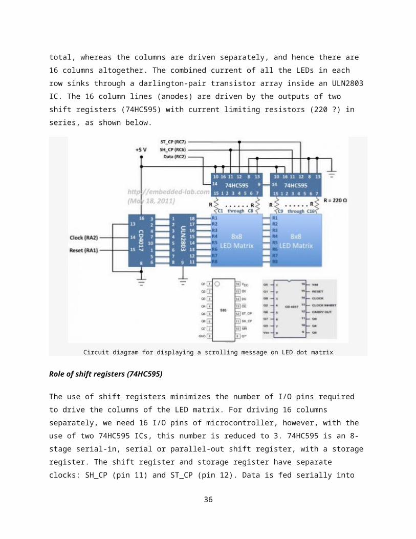
there are 8 combined rows in total, whereas the columns are driven separately, and
hence there are 16 columns altogether. The combined current of all the LEDs in
each row sinks through a darlington-pair transistor array inside an ULN2803 IC. The
30

16 column lines (anodes) are driven by the outputs of two shift registers (74HC595)
with current limiting resistors (220 ?) in series, as shown below.
Circuit diagram for displaying a scrolling message on LED dot matrix
Role of shift registers (74HC595)
The use of shift registers minimizes the number of I/O pins required to drive the
columns of the LED matrix. For driving 16 columns separately, we need 16 I/O pins
of microcontroller, however, with the use of two 74HC595 ICs, this number is
reduced to 3. 74HC595 is an 8-stage serial-in, serial or parallel-out shift register,
with a storage register. The shift register and storage register have separate clocks:
SH_CP (pin 11) and ST_CP (pin 12). Data is fed serially into the register through DS
pin (14) and is shifted on the positive-going transitions of the SH_CP input. However,
the data in each register does not appear at the output pin of 74HC595 unless it is
transferred to the storage register. This happens on a positive-going transition of
the ST_CP input. 74HC595 also provides a serial standard output, Q7’ (pin 9) for
cascading, which is needed in this experiment. The serial output of the first shift
31

register is connected to the serial input (DS pin) of the second shift register, so that
the 16-bit column data can be transferred serially through the DS pin of the first
shift register. This requires 16 clock pulses on SH_CP followed by a clock pulse on
ST_CP. The asynchronous reset pin (MR) is always pulled high (deactivated)
whereas the output enable (OE) pin is permanently grounded (always enabled).
Role of counter (CD4017)
As mentioned in the beginning of this article, this time the rows will be fast-scanned
from the top to the bottom, unlike the columns like we did in Lab 12. Eight I/O pins
are required to scan 8 rows in sequence. You can use the PORTB pins of PIC18F2550
for this purpose. But if you think you will need them for some other purpose (some
of PORTB pins have interrupt-on- change feature), you can use a port expander,
such as CD4017, that will serve the purpose and require only two I/O pins of
microcontroller. CD4017 is a 5-stage divide-by-10 Johnson counter with 10 decoded
outputs and a carry out bit. The counter is cleared to zero count by a logical “1” on
its reset line (15). The counter is advanced on the positive edge of the clock signal
(pin 14), when the clock inhibit pin (13) is grounded. The 10 decoded outputs are
normally in the logical “0” state and go to the logical “1” state only at their
respective time slot. Each decoded output remains high for 1 full clock cycle. The
carry-out signal completes a full cycle for every 10 clock input cycles and is used as
a ripple carry signal to any succeeding stages. The 8 rows of LED matrix are
sequentially connected to the decoded outputs, Q0- Q7, of CD4017 through
ULN2803 IC that has eight Darlington pairs, each of which provides a ground path to
sink the combined current of all LEDs in a row. At the end of every 8th clock cycle,
the microcontroller will reset the counter by issuing a logical “1″ to its Reset pin
(15).
The microcontroller pins used for driving these signals for 74HC595 and CD4017 are
shown below. A 10K pot is connected to RA0 pin of PIC18F2550 microcontroller that
will control the speed of the scrolling message on the LED matrix display.
32

Microcontroller I/O pins for driving the LED matrix
Circuit setup on breadboard with StartUSB for PIC board
Software
33

If you are unfamiliar with how static characters are displayed on a LED dot matrix, I
would recommend to read Lab 12 first. In row scanning, each row is selected for a
very short time (about 1 ms) and the columns are fed with appropriate logic levels.
By quickly scanning across the rows (> 100 times per second), and turning on the
respective LEDs in each column of that row, the persistence of vision comes in to
play, and we perceive the display image as still. The picture below shows the active
LEDs in each row to display the character ‘A’ on a 8×8 dot-matrix format. This
information for all printable ASCII characters (0-9, A-Z, a-z, etc) will be stored in a
two-dimensional constant array CharData[][8] in the program memory of
PIC18F2550.
8x8 dot matrix values for character A
Defining the column values for printable ASCII characters in 8x8 format
34

One question: “How would you find the right index of a particular character in this
array?” The answer is simple. This array is created sequentially for ASCII characters
starting from ‘Space’ (decimal value, 32) to ‘~’ (decimal value 126). So you need to
subtract 32 from the ASCII value of the character itself to get the corresponding row
index of CharData array. For example, if you want to display a dollar sign, $, its
ASCII value is 36 (decimal). If you subtract 32, you get 4, which in fact, is the right
row index of $ in CharData array (see above).
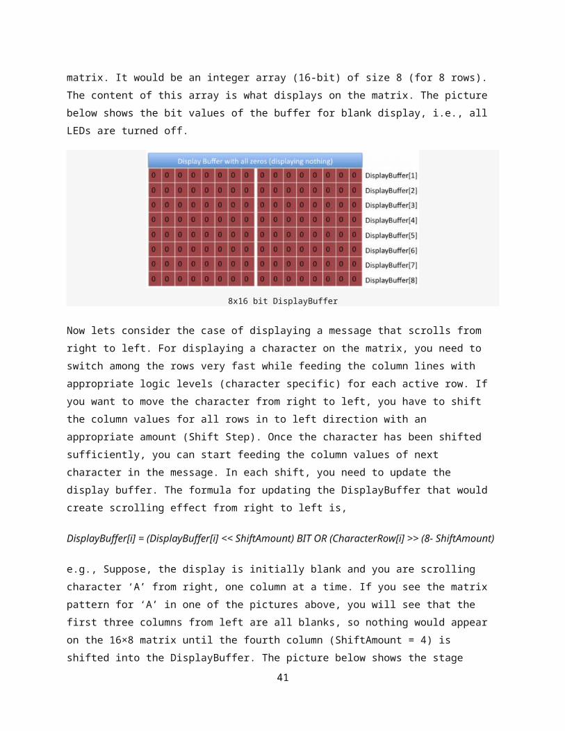
Now lets talk about the scrolling effect. We will also define a display buffer for
storing the bit information of 16×8 LEDs in the matrix. It would be an integer array
(16-bit) of size 8 (for 8 rows). The content of this array is what displays on the
matrix. The picture below shows the bit values of the buffer for blank display, i.e.,
all LEDs are turned off.
8x16 bit DisplayBuffer
Now lets consider the case of displaying a message that scrolls from right to left.
For displaying a character on the matrix, you need to switch among the rows very
fast while feeding the column lines with appropriate logic levels (character specific)
for each active row. If you want to move the character from right to left, you have to
shift the column values for all rows in to left direction with an appropriate amount
(Shift Step). Once the character has been shifted sufficiently, you can start feeding
the column values of next character in the message. In each shift, you need to
update the display buffer. The formula for updating the DisplayBuffer that would
create scrolling effect from right to left is,
35
DisplayBuffer[i] = (DisplayBuffer[i] << ShiftAmount) BIT OR (CharacterRow[i] >>
(8- ShiftAmount)
e.g., Suppose, the display is initially blank and you are scrolling character ‘A’ from
right, one column at a time. If you see the matrix pattern for ‘A’ in one of the
pictures above, you will see that the first three columns from left are all blanks, so
nothing would appear on the 16×8 matrix until the fourth column (ShiftAmount = 4)
is shifted into the DisplayBuffer. The picture below shows the stage where the
initially-blank DisplayBuffer has already been shifted to left by 7 columns
(ShiftAmount = 7). DisplayBuffer for row 1 was initially all zeros, ‘00000000
00000000’. The new DisplayBuffer for the first row after the character ‘A’ is partially
loaded (up to its 7 columns) is ‘00000000 00000111’. This can be obtained by first
shifting the previous value of DisplayBuffer to left by 7, which still gives
DisplayBuffer[1] all zeros. The first row of character ‘A’ in an 8×8 matrix format is
‘00001110’. If you shift this right by 8-7 = 1 step, we get ‘00000111’. If you bit-OR
this with the new DisplayBuffer[1], you will get ‘00000000 00000111’.
The value of ShiftAmount must be increased sequentially up to 8, after which the
8×8 character is fully loaded in to the display buffer. Then, ShiftAmount restarts
from 1 again and starts loading the next character from the right, while the display
buffer itself shifts left. This continues until all the characters in the message are
loaded.
36

Display Buffer after shifting 7 bits to the left
The following routine serially feeds the two shift registers with a 16-bit column
value.
void send_data(unsigned int temp){ unsigned int Mask = 0x0001, t, Flag; for (t=0; t<16; t++){ Flag = temp & Mask; if(Flag==0) Serial_Data = 0; else Serial_Data = 1; SH_Clk = 1; SH_Clk = 0; Mask = Mask << 1; }// Apply clock on ST_Clk ST_Clk = 1; ST_Clk = 0;}
And, the following code does the scrolling of message on to the matrix display. The
value of shift_step determines how many columns you want to shift at a time. I set
it to 1.
for (k=0; k<StringLength; k++){ for (scroll=0; scroll<(8/shift_step); scroll++) { for (ShiftAmount=0; ShiftAmount<8; ShiftAmount++){ index = message[k];
37

temp = CharData[index-32][ShiftAmount]; DisplayBuffer[ShiftAmount] = (DisplayBuffer[ShiftAmount] << shift_step)| (temp >> ((8-shift_step)-scroll*shift_step)); } speed = 10+ADC_Read(0)/10; for(l=0; l<speed;l++){ for (i=0; i<8; i++) { send_data(DisplayBuffer[i]); CD4017_Clk = 1; CD4017_Clk = 0; Delay_ms(1); } // i CD4017_Rst = 1; CD4017_Rst = 0; } // l } // scroll }
You can download the complete mikroC project files for this tutorial from the link
below.
Download mikroC project files
Dot matrix LED display. In this project, I show you how to control multi dot matrix LED with only 3 pins of micro-controller using multiplexing and cascading technique. Let's take a look at dot matrix. Dot matrix LED display is LEDs that are arranged in a rectangular configuration. Figure below shown a 5x7 dot matrix arranged and a common anode equivalent circuit. One 5 x 7 martix contains 35 LEDs, 12 control pins -- R1 to R7 and C1 to C5.
Software control multiplexing simply mean turning ON LED for a short period of time and doing this repeatedly for each LED. In this project, first step is turn ON the first column of the matrix LEDs then turn ON second column of the LED then do this though fifth column and repeat all step over. This require 12 pins of micro-controller, adding one more matrix LED require 5 more pin. Imagine if you want 10 matrix LED.
38

74HC595 74HC595 is a 8-bit serial input, 8-bit serial or parallel output. Figure below shown pin configuration and functional diagram of 74HC595.
39

74HC595 receives data in series and converts to parallel output. Data is shifted in to DS pin to shift register on rising edge on SH_CP input clock. When compleat 8-bit shifted in, giving rising edge of ST_CP to make data appear on Q0-Q7 pin (OE must be LOW). The Q7' is an output pin to make cascading by conect Q7' pin to DS pin of another 74H595. So that makes only 3 pins of micro-controller to control many matrix LED.
2 5x7 Dot matrix LED example. Figure shown below is a schematic that contain of a MCU, 3 74HC595s, 2 5x7 dot matrix LEDs, 5 transistors and several current limit resistors.
40
This project can be done with a small 8 pins MCU but I have PIC18F2620 in my development board so I decided to stick with it. 3 cascading 74HC595-- 2 to control column data, one to control row data with 5 transistor LEDs driver.
Now it's time for software control. Since data are sent in a series form, we need Shifting routine.
#define sClock LATB.F0#define sData LATB.F1#define sLoad LATB.F2
void Shift_OutMSB (char sd) { char i; char mask = 128; for (i=1; i<=8; i++){ if (!(sd&mask)) sData = 0; else sData = 1; sClock = 1;
41

delay_us (1); sClock = 0; mask = mask >> 1; }}
The routine convert 8-bits data to serial sData pin while clock sent to sClock pin, both sData and sClock must define, I used RB0 and RB1. 3 bytes data are transfer to matrix LED 2nd, matrix LED 1st, and column control (C1-C5) in order. LEDs are ON for a short time. The short time is about 4ms that make compleat 5 column take 20ms which is fast enough for the eyes can caught it was blink. Timer0 is configed as 8-bits timer with 1:16 prescaler and the system clock is 4Mhz internal oscillator. Timer0 rollover = 256*16 us, = 4096us (approximate 4 ms).
//******** clock source set up **************** IRCF2_bit = 1; IRCF1_bit = 1; IRCF0_bit = 0; //4Mhz clock SCS1_bit = 1; //internal osc //***** Timer0 setup ************************ T0CS_bit = 0; //Fosc/4 clock source. PSA_bit = 0; //Prescaler assigned to Timer0. T0PS0_bit = 1; //1:16 prescaler. T0PS1_bit = 1; T0PS2_bit = 0; TMR0IP_bit = 0; //timer0 low piority. T08bit_bit = 1; //timer0 is 8 bit. TMR0IE_bit = 1; //enable timer0 interrupt.
when Timer0 interrupt flag is set, the flag must be clear in software. Code below is interrupt routine.
void interrupt(){ char i; //timer0 is free-running at 1:16 prescaler causes interrupt every 4ms. if(TMR0IF_bit){ TMR0IF_bit = 0; //clear interrupt flag. counter++; //increment counter. if(counter >= 150) { //change pattern delay 600ms (4*150). toggle ^= 1; counter = 0; if(toggle){ for(i=0; i<10; i++){ display_mem[i] = pt2[i]; //load pattern2. } } else{ for(i=0; i<10; i++){ display_mem[i] = pt1[i]; //load pattern1. } } }
if(index > 4) index = 0; Shift_OutMSB(display_mem[index + 5]); //send data to second matrix led Shift_OutMSB(display_mem[index]); //send data to first matrix led switch (index){ //select which column to display case 0: Shift_OutMSB(1); break; case 1: Shift_OutMSB(2); break; case 2: Shift_OutMSB(4);
42

break; case 3: Shift_OutMSB(8); break; case 4: Shift_OutMSB(16); } //send Load clock to active 595 for diplay current column sLoad = 1; delay_us (1); sLoad = 0; index++; //increment to next column }}
Side scrolling message board. I built a small side-scrolling message board (1 x 12 characters) with 5x7 martrix LEDs using PIC16F876. The board can store 4 messages select by 2 switches and each message can have up to 59 characters. All message stores in EEPROM inside the PIC16F876, no extra EEPROM and bettery backup need. Each message can be change by PC terminal via RS-232. Below shown configuration of the message board.
43

44

Software Diagram.
45

46