towards the structural modeling of the topology of next
TRANSCRIPT

HAL Id: hal-01400264https://hal.inria.fr/hal-01400264v4
Submitted on 10 Nov 2017
HAL is a multi-disciplinary open accessarchive for the deposit and dissemination of sci-entific research documents, whether they are pub-lished or not. The documents may come fromteaching and research institutions in France orabroad, or from public or private research centers.
L’archive ouverte pluridisciplinaire HAL, estdestinée au dépôt et à la diffusion de documentsscientifiques de niveau recherche, publiés ou non,émanant des établissements d’enseignement et derecherche français ou étrangers, des laboratoirespublics ou privés.
Towards the Structural Modeling of the Topology ofnext-generation heterogeneous cluster Nodes with hwloc
Brice Goglin
To cite this version:Brice Goglin. Towards the Structural Modeling of the Topology of next-generation heterogeneouscluster Nodes with hwloc. [Research Report] Inria. 2016. �hal-01400264v4�
Towards the Structural Modeling of the Topology of
next-generation heterogeneous cluster Nodes with
hwloc
Brice GoglinInria Bordeaux – Sud-Ouest, LaBRI, University of Bordeaux
F-33400 Talence, [email protected]
Abstract
Parallel computing platforms are increasingly complex, with multiple cores, shared caches,and NUMA memory interconnects, as well as asymmetric I/O access. Upcoming architectureswill add a heterogeneous memory subsystem with non-volatile and/or high-bandwidth memorybanks.
Parallel applications developers have to take locality into account before they can expectgood efficiency on these platforms. Thus there is a strong need for a portable tool gathering andexposing this information. The Hardware Locality project (hwloc) offers a tree representation ofthe hardware based on the inclusion of CPU resources and localities of memory and I/O devices.It is already widely used for affinity-based task placement in high performance computing.
We present how hwloc represents parallel computing nodes, from the hierarchy of computingand memory resources to I/O device locality. It builds a structural model of the hardware tohelp application find the best resources fitting their needs. hwloc also annotates objects to easeidentification of resources from different programming points of view. We finally describe how ithelps process managers and batch schedulers to deal with the topology of multiple cluster nodes,by offering different compression techniques for better management of thousands of nodes.
1 Introduction
High performance computing relies on powerful computing nodes made of tens of cores and ac-celerators such as GPUs or Xeon Phi. The architecture of these servers is increasingly complexbecause these resources are interconnected by multiple levels of hierarchical shared caches and aNUMA memory interconnect. Execution performance now significantly depends on locality, i.e.where a task runs with respect to its data allocation in memory, or with respect to the other tasksit communicates with. It had a critical impact on the performance of parallel applications for along time, from distributed computing [26] to single servers [24].
Performance optimization of parallel applications requires a thorough knowledge of the hard-ware, and many research projects aim to model the platform to tackle this challenge. Besidesanalytic performance models, one solution consists in structural modeling of the hardware resourceorganization. Indeed, parallel developers need such information to properly use the platform. hwloc(Hardware Locality) is the de facto standard software for representing CPU and memory resources,and for binding software tasks in a portable and abstracted manner [1].
1
We identify two major types of affinity. First, tasks have affinities for hardware resources theyuse. This includes memory banks, caches and TLBs that contain some of their data as well asI/O devices such as accelerators and network interfaces. Moving a task away from one core cancause the performance to vary depending on the cores’ locality with regard to the I/O devicesused by the task [17]. The second kind of affinity is between tasks. Indeed, parallel applicationsoften involve communication, synchronization and/or sharing between some of the processes orthreads. It usually means that related tasks should be placed on neighbor cores to optimize thecommunication/synchronization performance between them [22]. However, the affinity can also bereversed when single tasks have strong needs. For instance, memory-intensive applications maywant to avoid sharing memory links or caches with others [15].
Applications can have several of these types of affinities simultaneously, even with conflictingneeds. We envision two ways to deal with these needs. First, tasks can be placed on the hardwareresources according to their affinities. For instance, MPI process placement based on the commu-nication scheme and on the platform topology is a very active area of research [11, 25, 14]. Then,the actual communication between tasks can be adapted to the existing placement. For instance,the existence and the size of a shared cache between processes can be a reason to switch from onecommunication strategy to another [3, 16]. The locality of I/O devices can also be used to bettertune collective operations [18, 9]. Moreover, batch schedulers or process managers try to manageclusters of such heterogeneous nodes in a global manner, making locality an important aspect,outside of nodes as well.
This paper describes how hwloc has evolved into the de facto central place for gathering local-ity information about all hardware subsystems in parallel platforms. Our contributions include astructural model based on physical locality and inclusion, as discussed in Section 2. This strategyis already successfully used by many high performance computing software for querying localityinformation. Then Section 3 describes how hwloc exposes a portable and abstracted view of thehardware by combining topology information from many sources, including operating systems,domain-specific libraries and platform-specific instructions. We finally present in Section 4 a con-tribution to the way batch schedulers and process managers apply cluster-wide allocation or place-ment policies. hwloc lets them manipulate, summarize, compress and/or compare the topologiesof multiple nodes from the front-end.
2 Modeling the Structure of Computing Platforms
hwloc is now used by most MPI implementations, many batch schedulers and parallel libraries1.We explain in this section why hwloc’s structural model is a good solution for their needs.
2.1 Modeling Platform for Performance Analysis
The complexity of modern computing platforms makes them increasingly harder to use, causingthe gap between peak performance and application performance to widen. Understanding theplatform behavior under different kinds of load is critical to performance optimization. Performancecounters is a convenient way to retrieve information about bottlenecks for instance in the memoryhierarchy [27] and apply feedback to better schedule the next runs [23]. The raw performance of
1A non-exhaustive list of hwloc users is available on the project webpage http://www.open-mpi.org/projects/
hwloc/.
2

a server may also be measured through different memory access workloads to predict the behaviorof kernels [20]. However these strategies remain difficult given the number of parameters that areinvolved (memory/cache replacement policy, prefetching, bandwidth at each hierarchy level, etc.),many of them being poorly documented.
At the scale of a cluster, performance evaluation has been a research topic much earlier becausenetwork communication caused slowdowns long before servers became hierarchical (when multicoreand NUMA processors emerged). The LogP model [6] may be used to describe the network perfor-mance and build a hierarchy of processors based on this experimental distance for better processplacement [5]. Improved performance models have been proposed since then to offer realistic simu-lation on larger platforms [4]. These approaches may also be combined for inter-node and intra-nodecommunication so as to weight the communication performance of all combinations of cores beforescheduling jobs [21]. Such an approach may actually also help experimentally rebuilding the entiretopology of the clusters for better task placement [10].
These results however lack a precise description of the structural model of the machine. Ex-perimental measurement cannot ensure the reliable detection of the hierarchy of computing andmemory resources such as packages, cores, shared caches and NUMA nodes. Indeed, they impactperformance in a different way, and it may vary significantly with the workload (memory footprintvs cache size, number of processes involved vs memory bandwidth, etc.). It explains why perfor-mance models only give hints about the impact of the platform on performance. On the otherhand, the structural modeling of the platform gives precise performance reports. OpenMP threadscheduling [2] or MPI process placement [14] are examples of scheduling opportunities that canbenefit from deep platform topology knowledge.
2.2 Structural Modeling of the Hardware as a Tree
The organization of computing resources in clusters is hierarchical: a cluster contain servers thatcontain processor packages, that contain cores, that optionally contain several hardware threads.Current AMD Opteron processors (63xx) also have an intermediate level called Compute Unitbetween packages and cores. Moreover, from a locality point of view, memory resources such ascaches and NUMA nodes can be considered as embedded into such computing resources: indeedNUMA nodes are usually attached to sets of cores2, while caches are usually placed between somecores and the main memory, Therefore we can sensibly extend a hierarchy of computing resourcesto a hierarchy of memory resources as depicted in Figure 1.
We represent the entire machine as a tree of resources organized by locality: the more thehardware threads share common ancestors (same NUMA node, shared caches, or even same core),the better locality between them is. This approach has several advantages:
• First the tree representation of the topology is very convenient because it exposes the naturalinclusion-based organization of the platform resources. Indeed binding memory near a coreor finding a shared cache between cores only requires to walk up the tree until we find therelevant ancestor object and/or walk down to iterate over children. We can easily iterate overcores and threads close to a given object in the tree, a very common operation in locality-awareruntimes.
Another solution would be to represent the structure as the generic graph whose nodes areresources and edges are physical connections. However, the concepts of inclusion, container
2Old architectures such as Itanium even had each NUMA node attached to several processors.
3

Machine (32GB total)
Package P#0
NUMANode P#0 (16GB)
L3 (6144KB)
L2 (2048KB)
L1i (64KB)
L1d (16KB)
Core P#0
PU P#0
L1d (16KB)
Core P#1
PU P#4
L2 (2048KB)
L1i (64KB)
L1d (16KB)
Core P#2
PU P#8
L1d (16KB)
Core P#3
PU P#12
L2 (2048KB)
L1i (64KB)
L1d (16KB)
Core P#4
PU P#16
L1d (16KB)
Core P#5
PU P#20
L2 (2048KB)
L1i (64KB)
L1d (16KB)
Core P#6
PU P#24
L1d (16KB)
Core P#7
PU P#28
NUMANode P#1 (16GB)
L3 (6144KB)
L2 (2048KB)
L1i (64KB)
L1d (16KB)
Core P#0
PU P#32
L1d (16KB)
Core P#1
PU P#36
L2 (2048KB)
L1i (64KB)
L1d (16KB)
Core P#2
PU P#40
L1d (16KB)
Core P#3
PU P#44
L2 (2048KB)
L1i (64KB)
L1d (16KB)
Core P#4
PU P#48
L1d (16KB)
Core P#5
PU P#52
L2 (2048KB)
L1i (64KB)
L1d (16KB)
Core P#6
PU P#56
L1d (16KB)
Core P#7
PU P#60
Figure 1: AMD platform containing Opteron 6272 processors, simplified to a single processor, andreported by hwloc’s lstopo tool. This processor package is made of two parts containing oneNUMA node and one L3 cache each. L2 and L1i caches are then shared by Compute Units pairsof cores, while the L1d is private to each single-thread core.
parent and contained children would not be obvious, making application queries less conve-nient.
• Secondly, this logical organization based on locality solves many portability issues by hid-ing platform specific parameters. Indeed vendor-specific configurations, BIOS or softwareupgrades may change the numbering of resources even if the processors are identical3. There-fore relying on hardware numbering of resources to perform explicit task placement makesprograms non-portable, even to a similar platform with the same processors but a differentBIOS (see Section 3.3).
On the other hand, relying on hwloc’s logical numbering of resources to perform explicit taskplacement makes programs more portable as it is based on the actual physical localities.
• Third, using a tree-structure is a good trade-off between performance and precision: while us-ing a graph to represent the architecture would be more precise in some cases, tree algorithmsare often much more efficient in both memory and time. Indeed, process placement techniquesoften rely on graph partitioning techniques (a communication graph must be mapped ontoan architecture graph) which are much more efficient when generic graphs are replaced withtrees. For instance, the Scotch partitioning software supports a Tleaf architecture definitionfor enabling specifically optimized algorithms on hierarchical platforms [19].
hwloc builds a Tree of Objects, from the root Machine (a single-image shared-memory system)to the leaves Processing Units (PU, that corresponds to hardware threads, logical processors, etc).It is based on the natural inclusive order of computing resources and the locality of memoryresources. Each hwloc object is characterized by a type, some hardware characteristics such as apackage number, and some optional parameters such as local cache or memory sizes. hwloc does notenforce the vertical ordering between these levels in the tree because some most modern processorsmay have two NUMA nodes per package (see Figure 1) while some Itanium machines have multiplepackages per NUMA node. hwloc just moves larger objects above smaller ones depending on thearchitecture inclusion characteristics.
3For instance, Processing Unit (PU) #0 and #4 are close in Figure 1 while #1 is located in another processor(not displayed).
4

The hwloc model is further extended to include I/O devices by attaching I/O objects based ontheir locality. If a PCI bus is close to a NUMA node, the corresponding hwloc objects are attachedas additional children to this NUMA node object, as depicted on Figure 2.
Machine (64GB total)
NUMANode P#0 (32GB)
Package P#0
L3 (20MB)
L2 (256KB)
L1d (32KB)
Core P#0
PU P#0
PU P#16
L2 (256KB)
L1d (32KB)
Core P#1
PU P#2
PU P#18
L2 (256KB)
L1d (32KB)
Core P#2
PU P#4
PU P#20
L2 (256KB)
L1d (32KB)
Core P#3
PU P#6
PU P#22
PCI 14e4:165f
eth1
PCI 1000:0073
sda
PCI 10de:1094
cuda0
8,0
NUMANode P#1 (32GB)
Package P#1
L3 (20MB)
L2 (256KB)
L1d (32KB)
Core P#0
PU P#1
PU P#17
L2 (256KB)
L1d (32KB)
Core P#1
PU P#3
PU P#19
L2 (256KB)
L1d (32KB)
Core P#2
PU P#5
PU P#21
L2 (256KB)
L1d (32KB)
Core P#3
PU P#7
PU P#23
PCI 15b3:1003
mlx4_0
PCI 10de:1094
cuda1
8,0
Figure 2: Topology of a dual-Xeon E5 host with GPUs (cuda0, cuda1), network (eth1), InfiniBand(mlx4 0) and disk (sda) connected to different packages, simplified and reported by hwloc’s lstopotool.
The hwloc programming interface allows walking the tree edges to find ancestors or child objectsof a given type (e.g. when looking for the NUMA node close to a given core), iterate over objectsof a same type (e.g. when binding processes on cores), etc. hwloc offers a convenient way to applymapping policies [12] or partitioning algorithms by matching applications affinity graphs onto thehwloc tree of hardware resources [14]. More use cases and hwloc v1.0 early design details arepresented in [1].
2.3 Limits to the Tree Model
We explained in the previous section why modeling the structure of a parallel platform as a tree isconvenient, we now list several drawbacks of this approach.
One critique against the model is its lack of topology information within single levels of thetree. For instance, Xeon E5 and Xeon Phi processors are actually made of cores connected byan internal ring. hwloc only exposes them as an unordered list of cores, without any informationabout distances between specific cores. The upcoming Intel Knights Landing processor will eveninterconnect core tiles by a mesh [13]. Although this knowledge has been used to improve memoryallocation in Knights Corner Xeon Phi [7], it remains hardly usable for applications in practice.Therefore, it is not clear yet if exposing such information would be of a lot of interest to hwlocusers.
The same argument could apply to the NUMA memory interconnect since it is not always acomplete graph. Indeed the performance of remote NUMA node memory access may vary with thephysical distance4. This organization is available as a latency matrix (reported by the hardwareACPI tables, or provided by micro-benchmarks) and exposed by hwloc to annotate the set of NUMA
4On a 12-processor SGI Altix UV2000, the stream Triad benchmark bandwidth drops from 31GB/s locally, to7.4GB/s when accessing memory from the neighbor NUMA nodes, and down to 5.3GB/s from the farthest NUMAnode.
5

node objects. Moreover, hwloc uses this information to create additional hierarchical Group objectsthat contain close NUMA nodes. Large NUMA platforms are therefore represented with a hierarchyof Groups between the Machine and NUMA node objects so that the physical organization as racksand blades is exposed5.
Machine (2048MB total)
Package P#0
Normal NUMA Node P#0 (1024MB)
Core P#0
PU P#0
Core P#1
PU P#1
Core P#2
PU P#2
Core P#3
PU P#3
HBM NUMA Node P#1 (1024MB)
Figure 3: hwloc’s view of a quad-core processor with 1GB of high-bandwidth memory (HBM) and1GB of normal memory.
Another issue with the tree model is upcoming architectures with different kinds of memory. Forinstance, the Intel Knights Landing processor will feature high-bandwidth memory (MCDRAM)inside the package while still using normal (DDR) external memory [13]. It means that each coremay have two distinct local NUMA nodes, hence two parents: a normal one, and a faster butsmaller one. Another constraint is that memory allocation should not go into the smaller andfaster MCDRAM unless specifically requested. It means that the normal memory should appearcloser to cores than the MCDRAM (even if the MCDRAM is physically closer). hwloc thereforecurrently exposes the MCDRAM as another NUMA node object on the side as shown on Figure 3.This work is part of a larger rework on the hwloc memory model. Indeed, upcoming non-volatilememory DIMMs will also be attached to processors and be byte-accessible. The exact way thesenew memories will be exposed to the operating system is still under standardization. But weenvision the idea of moving NUMA node objects to the side and rather attach them to processorlike I/O devices.
Finally, considering the variety of network fabrics, the hwloc tree model does not work wellfor representing multiple machines and their interconnection network. This issue will be addressedspecifically in Section 4.5.
3 Discovering and Organizing Hardware Information
We describe in this Section how hwloc discovers the existing computing, memory and I/O resources,as well as their locality before explaining how they are actually exposed within the tree in aabstracted and portable manner.
3.1 Where and How to Gather Topology Information
The importance of locality led many developers to retrieve topology information within their ap-plications or libraries. Unfortunately, this work is difficult because of the amount and variety of
5Some examples of latency-based grouping are available at https://www.open-mpi.org/projects/hwloc/
lstopo/.
6
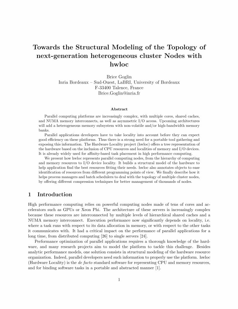
the sources of locality information, ranging from operating system, to direct hardware query andhigh-level tools.
Linux is widely used in high performance computing. Unfortunately, its ability to report topol-ogy information was designed over more than ten years and therefore suffers from a partial andnon-uniform interface. Many hardware details are available from the sysfs virtual file system (/sys)but it misses processor details (only available in /proc/cpuinfo) and I/O information such as net-work connectivity. Moreover, some of these files are in human-readable format, while some otherpieces of information are split into many different machine-readable files. Extracting locality infor-mation from an application is therefore a lot of work.
Convenient topology discovery should be available in higher-level libraries that hide the difficultyof parsing low-level system files or architecture-specific registers. On Linux, numactl6 possessesknowledge of NUMA, CPU and I/O localities but lacks caches. Moreover, its programming interfaceis unstable, and it was primarily designed for binding tasks: it cannot be used for querying detailsabout hardware characteristics.
Some processors have dedicated instructions for retrieving topology information such as CPUIDon x86. However, applications relying on this feature need to be updated for every new micro-architecture because special values with new meanings are often added and have to be supported.The operating system usually takes care of these cases, so these processor-specific instructionsshould not be needed in topology-aware applications, as long as the OS is recent enough.
Caches CPUs Multicores Affinity NUMA PCI Network Storage InfiniBand
/sys/sys /sys
x86 CPUID
lscpu
ethtoolpciutils libblkid libibverbs
/proc/cpuinfo
numactl
lshwlshw
Hardware to Discover
Operating-systemAPIs and virtual files
Low-level Libraries
High-level Tools
CPU-specific Instructions
Figure 4: Overview of existing sources of locality information on Linux.
As shown on Figure 4, many libraries exist for querying the topology of specific subsystems,for instance pciutils for PCI7, libibverbs for InfiniBand, CUDA for NVIDIA GPUs, etc. Unfortu-nately, there is almost no interoperability between these libraries and other topology-related tools.Therefore, we often have to combine information extracted from different sources, which can be atricky process: for instance, it is necessary to query sysfs, pciutils and CUDA when looking for thelocality of a NVIDIA GPU with regard to host CPUs.
Some higher level tools such as lscpu or lshw8 merge the information from several sourcesbut they were only designed for displaying the topology, without any programming interface forquerying. In addition, some non-Linux operating systems may have better interfaces but they lackpart of the information. For instance, Solaris does not report cache information, but the CPUIDinstruction may detect it on x86 platforms.
In conclusion, all these sources of information still have to be used concurrently for a developerto gather locality information about all hardware resources. There is therefore a need for a portable,
6http://oss.sgi.com/projects/libnuma/7http://mj.ucw.cz/sw/pciutils/8http://ezix.org/project/wiki/HardwareLiSter
7

system-wide topology discovery tool that combines all these pieces and exposes the information ina convenient and portable programming API. hwloc has been designed from the start to be thisneeded portability layer.
3.2 Combining Multiple Sources
hwloc’s discovery mechanism is based on several components9, each gathering information fromsome specific sources (operating system, hardware, low-level libraries, etc.), as described on Fig-ure 5. These components are ordered by priority that we defined empirically based on the com-pleteness and reliability of the information they provide. Each component also defines a list ofconflicting components to avoid redundant topology information (that could even be different incase of bugs).
If any, the operating-system-specific component is loaded first (on Linux, it reads CPU, cacheand NUMA information from /proc and /sys virtual files). Then, the CPU-specific componentis invoked to add missing information (the x86 component detects additional CPU and cachecharacteristics). Then a PCI component takes care of gathering the locality of PCI bus, beforeI/O-specific components attach objects describing GPUs, NIC, accelerators, etc.
hwloc library API
command-linetools
core
combined components globalcomponentsI/OplatformOS
XMLLinux Win BG/Q PCI CUDA
CPU
x86 Synt
Figure 5: hwloc’s component-based organization.
This component model lets user or administrator tune the information gathering process in caseof buggy information. For instance, some Linux kernels report buggy cache information for AMDprocessors, that may be worked around by loading the x86 component first (the Linux componentthen only discovers what x86 did not). The user is advised when such a workaround is recommendedbut it should not be automatically enabled. Indeed the exact list of affected platforms is hard todefine and may even change in the future. The only exception is for platform-specific components(for BlueGene/Q and Fujitsu Sparc-based servers) which are automatically enabled because it isknown that only one model of these exists and that their operating-system topology support willremain poor.
Finally some global components are standalone and cannot be combined because they alreadyprovide all topology information (XML and Synthetic topologies are described in Section 4).
3.3 Locating and Identifying Resources
Applications typically use the hwloc tree for locating where they are currently running, findingneighbor objects, consulting object attributes (see Section 3.4), and binding tasks or memory.There is a need for easy ways to locate and identify specific objects in a portable and abstractedmanner.
9hwloc v1.11 embeds 10 OS components, 6 I/O, 1 platform-specific, 1 CPU-specific, and 3 global components.
8
Machine (2048MB total)
NUMANode P#0 (1024MB)
Core P#0
PU P#0
PU P#4
Core P#1
PU P#2
PU P#6
NUMANode P#1 (1024MB)
Core P#2
PU P#1
PU P#5
Core P#3
PU P#3
PU P#7
(a) PU numbering by NUMA node first, then bycore, then by PU.
Machine (2048MB total)
NUMANode P#1 (1024MB)
Core P#0
PU P#0
PU P#2
Core P#1
PU P#1
PU P#3
NUMANode P#0 (1024MB)
Core P#2
PU P#4
PU P#6
Core P#3
PU P#5
PU P#7
(b) PU numbering by core first, then by PU, thenby NUMA node; out-of-order NUMA node num-bering.
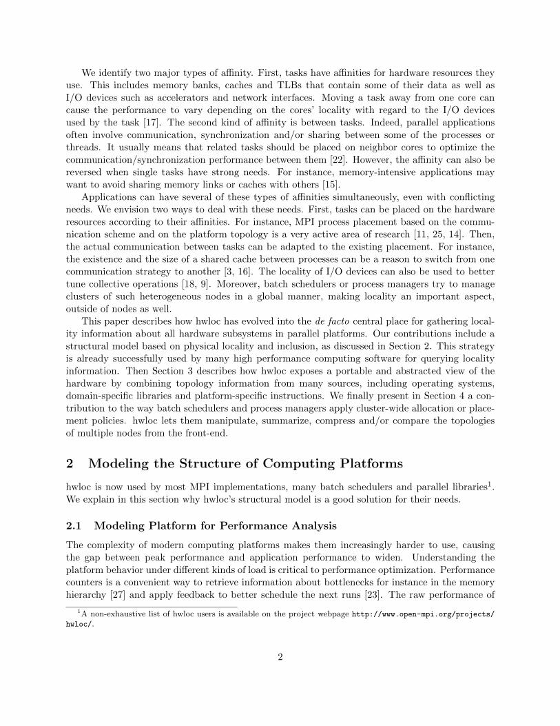
Figure 6: Numbering of the processing units (PU) and NUMA nodes on dual-package dual-corehyper-threaded platforms. Two inter-dependent tasks running on logical processors 0 and 1 areactually not close to each other on these platforms. The binding cannot be portable unless it isspecified as positions within the hierarchy of resources instead of as PU numbers. Memory bindingis also non-portable because the relative ordering of NUMA nodes is different.
Computing and memory resources can be identified by indexes provided by the hardware andoperating system (for instance the hardware thread that executes a given task). Unfortunately,these indexes are not portable from one machine to another because different vendors, BIOS versionsor operating systems often use different ways to order CPU cores. It leads to cases where a standarddual-package platform can have up to 8 different numbering schemes in practice (see examples onFigure 6). hwloc therefore provides all these resources with a logical index that is portable becauseit is defined by the position in the hierarchical tree. Application may use such indexes to find outwhere they are running or where memory buffers are allocated, or bind new tasks to specific coresand memory buffers to specific NUMA nodes.
Managing I/O devices is more difficult because there are many kinds of these, and becauseapplications do not actually natively use them like CPUs or memory. Indeed applications commu-nicate on the network using Sockets, write to files, or use CUDA or OpenCL structures for runningkernels on GPUs. They use such software handles instead of using PCI devices explicitly, so offeringthe locality of PCI devices is not actually useful to end-users. hwloc therefore offers different waysfor application to locate the I/O devices they want to use:
• hwloc inserts OS device objects in the topology tree to represent these software handles(CUDA device, network interface, etc.) inside the corresponding physical devices (PCI ob-jects). They are annotated with a kind attribute and a name in particular that lets applica-tions identify them (see eth1 and cuda0 among others on Figure 2, or cuda0 and mic1 onFigure 7). An application willing to use the first CUDA device just has to ask for the firstOS device of kind CUDA, walk up the tree to find out which NUMA node is physically closeto the corresponding GPU, and optionally walk down to find the local cores.
• hwloc provides interoperability helpers for the majority of user-space interfaces to high-performance devices (OpenCL, CUDA, Intel Xeon Phi co-processors, etc.). They translateapplication software handles into hwloc concepts and the corresponding locality information.For instance an application using InfiniBand will be able to retrieve the hwloc locality of thestruct ibv_device that it already uses for posting RDMA requests.
9

Binding a process on cores close to a given device is such a common need (especially to performdevice micro-benchmarking), that hwloc can do it automatically. For instance, the hwloc-bind
command-line tool can be used as follows to execute the given program close to the OS deviceidentified by its name with the os= prefix:
$ hwloc-bind os=mlx4_0 infiniband_benchmark
$ hwloc-bind os=cuda1 cuda_benchmark
$ hwloc-bind os=mic0 xeon_phi_benchmark
3.4 Exposing Hardware Characteristics
hwloc represents computing and memory objects using an exhaustive set of widespread resourcetypes (PU, core, cache, package, NUMA node, machine, PCI, etc.). They may have type-specificattributes such as the memory size for NUMA nodes, the cache type and size, or bus ID for PCIdevices. However, these static attributes cannot exhaustively cover the wide variety of hardwarecharacteristics such as the CPU model and features, GPU memory and processor details, networkaddress configuration, etc.
Machine (32GB total)
NUMANode P#0 (32GB)
Package P#0
L3 (20MB)
L2 (256KB)
L1d (32KB)
L1i (32KB)
Core P#0
PU P#0
PU P#16
L2 (256KB)
L1d (32KB)
L1i (32KB)
Core P#1
PU P#1
PU P#17
PCI 10de:1094
cuda0
5375 MB
L2 (768 kB)
14 MP x (32 cores + 48 kB)
8,0
PCI 8086:225c
mic1
61 cores
15 GB
Figure 7: Object attributes include cache types (L1i, L3, etc), memory sizes, PCI device and vendornumbers, PCI link speed, Xeon Phi memory and cores, CUDA memory and multiprocessors, aswell as CPU vendor and model (not displayed here).
To be as descriptive as possible, hwloc even allows objects to be annotated with custom at-tributes. They are store as pairs of key and value strings, such as Address=00:11:22:33:44:55. Toavoid requiring many string operations in applications, this mechanism is only used for uncommonattributes (widely-used attributes such as cache sizes are still stored as static fields within theobject structure). This feature is notably used by Intel and Oracle-specific drivers for dynamicallyoptimizing the Open MPI implementation on their platforms.
Each object usually contains at most a few key-value pairs, especially OS devices that describeGPU characteristics, NIC addresses, etc. (see Figures 7 and 8). These can be useful to distinguishbetween otherwise identical devices in a node or identical hosts in a network. Indeed, we need to
10
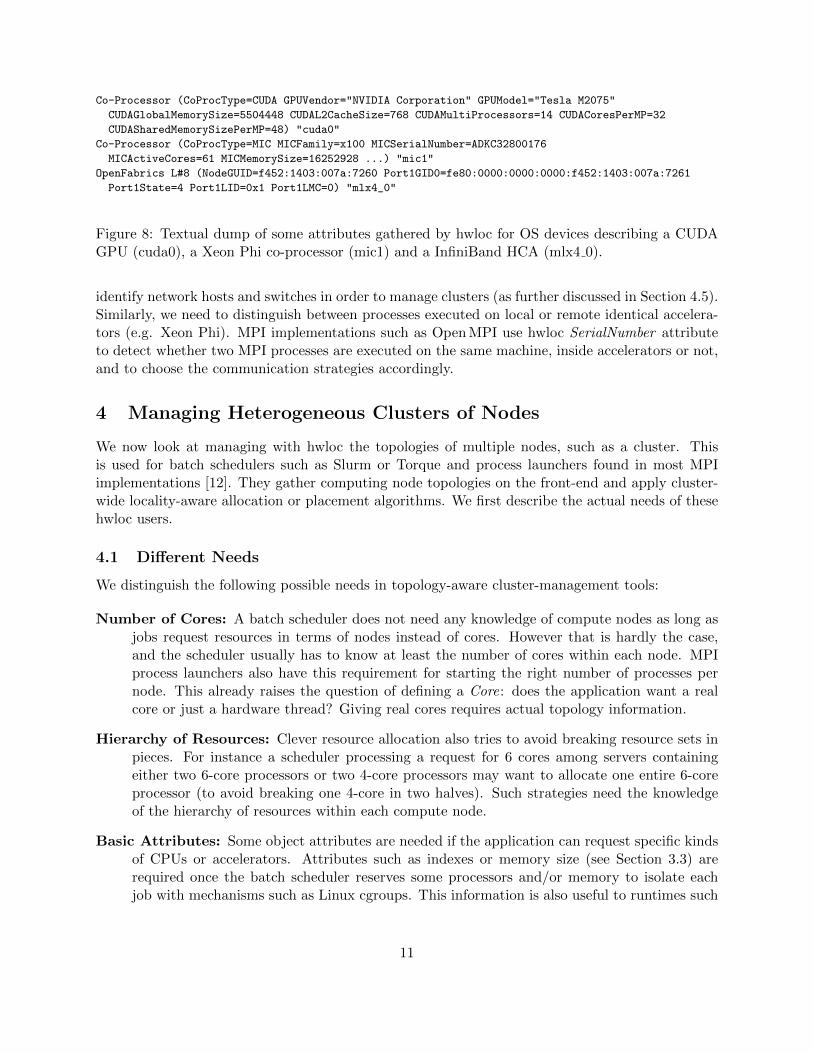
Co-Processor (CoProcType=CUDA GPUVendor="NVIDIA Corporation" GPUModel="Tesla M2075"
CUDAGlobalMemorySize=5504448 CUDAL2CacheSize=768 CUDAMultiProcessors=14 CUDACoresPerMP=32
CUDASharedMemorySizePerMP=48) "cuda0"
Co-Processor (CoProcType=MIC MICFamily=x100 MICSerialNumber=ADKC32800176
MICActiveCores=61 MICMemorySize=16252928 ...) "mic1"
OpenFabrics L#8 (NodeGUID=f452:1403:007a:7260 Port1GID0=fe80:0000:0000:0000:f452:1403:007a:7261
Port1State=4 Port1LID=0x1 Port1LMC=0) "mlx4_0"
Figure 8: Textual dump of some attributes gathered by hwloc for OS devices describing a CUDAGPU (cuda0), a Xeon Phi co-processor (mic1) and a InfiniBand HCA (mlx4 0).
identify network hosts and switches in order to manage clusters (as further discussed in Section 4.5).Similarly, we need to distinguish between processes executed on local or remote identical accelera-tors (e.g. Xeon Phi). MPI implementations such as Open MPI use hwloc SerialNumber attributeto detect whether two MPI processes are executed on the same machine, inside accelerators or not,and to choose the communication strategies accordingly.
4 Managing Heterogeneous Clusters of Nodes
We now look at managing with hwloc the topologies of multiple nodes, such as a cluster. Thisis used for batch schedulers such as Slurm or Torque and process launchers found in most MPIimplementations [12]. They gather computing node topologies on the front-end and apply cluster-wide locality-aware allocation or placement algorithms. We first describe the actual needs of thesehwloc users.
4.1 Different Needs
We distinguish the following possible needs in topology-aware cluster-management tools:
Number of Cores: A batch scheduler does not need any knowledge of compute nodes as long asjobs request resources in terms of nodes instead of cores. However that is hardly the case,and the scheduler usually has to know at least the number of cores within each node. MPIprocess launchers also have this requirement for starting the right number of processes pernode. This already raises the question of defining a Core: does the application want a realcore or just a hardware thread? Giving real cores requires actual topology information.
Hierarchy of Resources: Clever resource allocation also tries to avoid breaking resource sets inpieces. For instance a scheduler processing a request for 6 cores among servers containingeither two 6-core processors or two 4-core processors may want to allocate one entire 6-coreprocessor (to avoid breaking one 4-core in two halves). Such strategies need the knowledgeof the hierarchy of resources within each compute node.
Basic Attributes: Some object attributes are needed if the application can request specific kindsof CPUs or accelerators. Attributes such as indexes or memory size (see Section 3.3) arerequired once the batch scheduler reserves some processors and/or memory to isolate eachjob with mechanisms such as Linux cgroups. This information is also useful to runtimes such
11

as MPI process launchers [12], or placement algorithms such as TreeMatch [14] that maptasks to hardware resources.
Full Attributes: When job allocation or task placement is performed using I/O locality, or whenruntimes adapt their decisions to specific object information, the full topology of the machineis required.
We describe in the next sections how hwloc addresses these requirements.
4.2 Full XML Topologies
Managing the topology of multiple nodes requires a way to manipulate remote node topologies.We explained in the previous section that the full details of the topology may not be useful in allcases. However hwloc still supports that need anyway by allowing compute nodes to dump theirentire topology to a XML file (or memory buffer) that can be transferred through a network andreloaded by the manager remotely. The loaded topology is strictly identical except that it cannotbe used for actually binding task and memory since the local hardware is different.
This is useful for developing topology-aware algorithms and testing on a variety of differentplatform topologies without actually having access to these platforms. But it is also already widelyused by batch schedulers and MPI process launchers: each compute node sends a XML copy ofits local topology to the front-end node which implements the allocation/placement policy cluster-wide, before actually starting processes on the compute nodes. This strategy matches the FullAttributes case in Section 4.1.
XML also has the advantage of being very easy to load, much easier than rereading topologyinformation from the different sources as explained in Section 3.2. Gathering the topology informa-tion natively on Linux indeed implies to read information from several hundreds of files under /sysand /proc. A naive MPI implementation running one process per core would load the topologyonce per core, causing all these files to be accessed by all cores simultaneously. Table 1 showsthat the native Linux discovery does not scale well with the number of cores working in parallel(contention in the Linux kernel file-system locking code). On the other hand, XML import scaleswell. It also shows that very large machines may benefit from always loading from XML (up to 70xfaster) even when not performing multiple discoveries simultaneously.
Table 1: hwloc topology discovery time depending on the source, either native Linux discovery, orXML import. On each host, we measure the time for a single discovery on one core, and for allcores discovering simultaneously their own copy of the topology.
Host 16 cores 16 cores 160 coreswithout I/O with 3 GPUs SGI Altix UV
# Processes 1 16 1 16 1 160Linux 26 ms 1 s 210 ms 6 s 390 ms 107 sXML 3 ms 7 ms 3 ms 7 ms 12 ms 22 ms
XML buffer size 34 kB 39 kB 241kB
However the XML export has the drawback of putting pressure on the network and front-endnode by transferring lots of data from compute nodes. Indeed the size of hwloc XML exports scales
12
in O(P log P ) with P the number of cores10. Deeper hierarchies also generate slightly larger XMLs(O(log D) where D is the number of hierarchy levels in the machine) but we do not expect manynew hierarchy levels to appear in hardware in the future.
Table 1 shows that current computing nodes generate XML files whose size varies from tensto hundreds of kilobytes. It is hard to predict whether the actual transfer of tens of thousands ofsuch files on a supercomputer would be an important issue in term of performance. At least, theworkload on the front-end for processing these XML topologies will likely be problematic. Thereforethere is a need for alternative ways to describe the topologies of remote nodes.
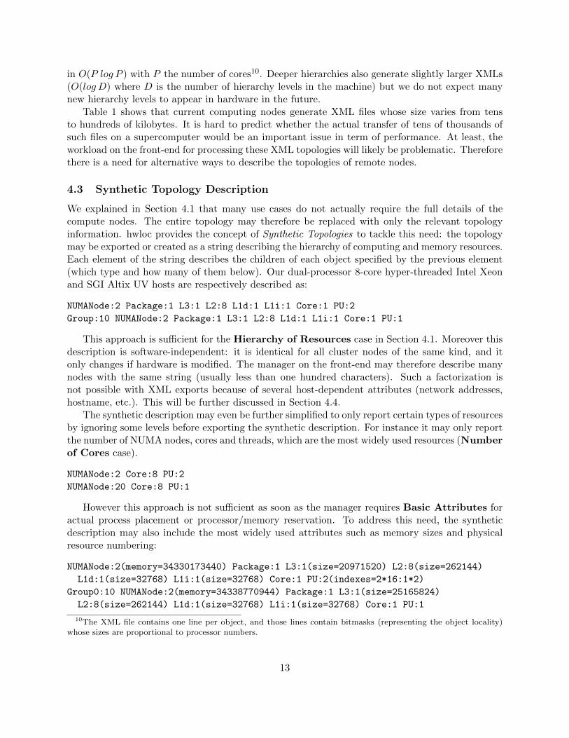
4.3 Synthetic Topology Description
We explained in Section 4.1 that many use cases do not actually require the full details of thecompute nodes. The entire topology may therefore be replaced with only the relevant topologyinformation. hwloc provides the concept of Synthetic Topologies to tackle this need: the topologymay be exported or created as a string describing the hierarchy of computing and memory resources.Each element of the string describes the children of each object specified by the previous element(which type and how many of them below). Our dual-processor 8-core hyper-threaded Intel Xeonand SGI Altix UV hosts are respectively described as:
NUMANode:2 Package:1 L3:1 L2:8 L1d:1 L1i:1 Core:1 PU:2
Group:10 NUMANode:2 Package:1 L3:1 L2:8 L1d:1 L1i:1 Core:1 PU:1
This approach is sufficient for the Hierarchy of Resources case in Section 4.1. Moreover thisdescription is software-independent: it is identical for all cluster nodes of the same kind, and itonly changes if hardware is modified. The manager on the front-end may therefore describe manynodes with the same string (usually less than one hundred characters). Such a factorization isnot possible with XML exports because of several host-dependent attributes (network addresses,hostname, etc.). This will be further discussed in Section 4.4.
The synthetic description may even be further simplified to only report certain types of resourcesby ignoring some levels before exporting the synthetic description. For instance it may only reportthe number of NUMA nodes, cores and threads, which are the most widely used resources (Numberof Cores case).
NUMANode:2 Core:8 PU:2
NUMANode:20 Core:8 PU:1
However this approach is not sufficient as soon as the manager requires Basic Attributes foractual process placement or processor/memory reservation. To address this need, the syntheticdescription may also include the most widely used attributes such as memory sizes and physicalresource numbering:
NUMANode:2(memory=34330173440) Package:1 L3:1(size=20971520) L2:8(size=262144)
L1d:1(size=32768) L1i:1(size=32768) Core:1 PU:2(indexes=2*16:1*2)
Group0:10 NUMANode:2(memory=34338770944) Package:1 L3:1(size=25165824)
L2:8(size=262144) L1d:1(size=32768) L1i:1(size=32768) Core:1 PU:1
10The XML file contains one line per object, and those lines contain bitmasks (representing the object locality)whose sizes are proportional to processor numbers.
13

Resource numbering is only displayed if non linear. 2*16:2*1 is a hierarchical round-robin speci-fication describing that physical PU indexes are ordered as 0, 16, 1, 17, ..., 14, 30, 15, 31 on ourdual-Xeon host.
One drawback of synthetic topology description is that it does not currently support I/O devices.This would require to define which I/O devices are most-likely useful to add to the syntheticdescription (current servers contains several dozens of PCI devices, most of them being virtual anduninteresting for locality problems). This feature is currently under early design for future hwlocreleases.
4.4 Differences Between (Almost) Identical Cluster Nodes
XML and synthetic topology descriptions have both advantages and drawbacks, but the gap be-tween them is quite large. One way to bridge that gap is to factorize similarities between differentnodes described as XML. It is an interesting approach in clusters to avoid having to manipulate ahuge number of topologies at the same time on the front-end. We identified three actual possibledifferences between cluster node topologies:
• different kinds of nodes (e.g. compute node vs fat node vs GPU nodes): topologies arevery different;
• modified nodes (BIOS upgrade, software update, or hardware replacement): topologiesmay be different;
• similar nodes with different identification numbers such as network addresses, hostname,etc.
In the similar case, only some key/value pair attributes are modified. In other cases, the tree struc-ture can be different. Therefore, we added to hwloc the ability to compute the difference between 2similar nodes by recording which attributes have been modified. This lossless compression consistin identifying a few reference nodes whose topologies will be entirely stored (uncompressed). Allother nodes are then compressed by only storing the difference between their topology and one ofthe references. This feature is already used in the netloc submodule of hwloc (further described inSection 4.5).
Table 2: Memory consumed when loading the topologies of all nodes of a cluster within a singleprocess. Topologies were either stored as full topologies (uncompressed), or as a few reference fulltopologies and many differences against one of these references.
Total Full topologies DifferencesPlafrim cluster = 21+65+16+9 compute nodes + 5 fat + 6 sshUncompressed 42 MB 122 × 345 kB N/ACompressed 11 MB 18 × 622 kB 104 × 2.03 kB
Avakas cluster = 264 compute + 2 phi + 4 fat + 4 visu + 2 sshUncompressed 110 MB 276 × 402 kB N/ACompressed 6.9 MB 12 × 539 kB 264 × 1.63 kB
Table 2 presents the memory occupancy improvement based on the compression of the topologiesof two clusters11. Each cluster is made of different kinds of nodes (6 for Plafrim and 5 for Avakas),
11The hwloc-compress-dir utility was used.
14

but we observe more reference topologies (respectively 18 and 12) because of the modified caseabove. However, many topologies can indeed be reduced from several hundreds of kilobytes downto 1 or 2 kB of differences in memory. Full topologies seem bigger in the compressed case becausethe share of fat nodes among reference topologies is higher.
Each difference is actually made of about 10 key/value pair attribute changes. We could evenimprove compression further by ignoring keys that are not needed by the target application (forinstance the platform serial number, or the MAC addresses if only InfiniBand is used).
4.5 Multiple Node Topology
Finally, we look at how to manage a full, cluster-wide topology. In hwloc 1.4, we introduced aCustom API to assemble the topologies of multiple nodes into a global single one. It lets theapplication build a hierarchy of Groups (that represent switches) and attach node topologies aschildren.
However, the resulting topology must respect hwloc’s tree model while networks interconnectingnodes may be a random graph. We explained in Section 2.3 that latency matrices can be usedto annotate some levels of the tree but this idea is only satisfying for simple topologies such asNUMA interconnects or package rings. high performance fabrics can be made of dragonfly or torustopologies that cannot be represented as such an annotated tree.
System (192GB total)
Machine P#0
NUMANode P#0 (32GB)
Package P#0
Core P#0
PU P#0
PU P#16
NUMANode P#1 (32GB)
Package P#1
Core P#0
PU P#8
PU P#24
PCI 8086:1521
eth0
PCI 8086:1521
eth1
Machine P#0
NUMANode P#0 (32GB)
Package P#0
Core P#0
PU P#0
PU P#16
NUMANode P#1 (32GB)
Package P#1
Core P#0
PU P#8
PU P#24
PCI 8086:1521
eth0
PCI 8086:1521
eth1
Machine P#0
NUMANode P#0 (32GB)
Package P#0
Core P#0
PU P#0
PU P#16
NUMANode P#1 (32GB)
Package P#1
Core P#0
PU P#8
PU P#24
PCI 8086:1521
eth0
PCI 8086:1521
eth1
Figure 9: Custom topology made of 3 servers assembled by their Machine root object. They areactually physically connected to the network by their eth0 and eth1 interfaces that are close totheir second NUMA node.
Moreover, the Custom API always attaches node topologies by the root of their tree (the entireMachine object, see Figure 9). This is inconsistent with the network locality inside the nodesbecause network interfaces (or InfiniBand HCAs) are often attached to a single NUMA node, andbecause there can be multiple interfaces per node.
Therefore, assembling multiple nodes into a global hwloc topology tree does not seem convenient.That is why the Custom API has been removed from the upcoming hwloc 2.0 release. There is anongoing work to develop a hwloc submodule called netloc that will not enforce a tree model [8].
There is a netloc graph describing the network and there are hwloc topologies for each node.In addition netloc also offers ways to translate handles from one world (hwloc OS devices forNICs) to the other (NIC ports in the network graph). One drawback of this new approach isthat there is no global structure describing the entire cluster. This would be an issue if batchschedulers or process managers had cluster-wide algorithms handling both the inter-node and intra-node cases simultaneously. Fortunately, there is no such need: the inter-node policy may be appliedby weighting nodes based on their number of cores, while the intra-node policy is applied later
15
separately.
5 Conclusion and Future Works
The increasing complexity of computing platforms raises the need for developers to understandthe hardware organization and adapt their application layout. As part of the overall optimizationprocess, there is a strong need for a tool modeling the platform, and hwloc is currently the mostpopular software for exposing a structural view of the topology of CPUs and memory. This approachis orthogonal to experimental performance models that give hints about the actual behavior of theresources exposed by hwloc.
We have presented in this article why and how the hwloc model has been designed as a hierarchi-cal structural model, describing the locality of computing, memory and I/O resources. It combineslocality information from many sources and offers APIs to interoperate with device-specific libraries.The hwloc tree also exposes many hardware attributes to help applications identify the resourcesthey use, place tasks near them or adapt their behavior to their locality.
hwloc also offers ways to manipulate the topology of multiple nodes so that batch schedulers orMPI process managers may apply resource allocation and task placement policies between nodesand inside nodes. Multiple node topologies can be consulted offline, compared, compressed orsynthetized depending on the actual topology information requirements.
All the features listed in this paper are actually implemented and ready to use in hwloc re-leases12. On-going work is now focusing on support for next-generation memory architectures withdifferent kinds of memory (high-bandwidth, non-volatile) as discussed in Section 2.3.
Acknowledgments
Some of cluster node topologies used in this study were provided by the computing facilities MCIA(Mesocentre de Calcul Intensif Aquitain) of the Universite de Bordeaux and of the Universite dePau et des Pays de l’Adour.
Some experiments presented in this paper were carried out using the PLAFRIM experimentaltestbed, being developed under the Inria PlaFRIM development action with support from BordeauxINP, LaBRI and IMB and other entities: Conseil Regional d’Aquitaine, Universite de Bordeauxand CNRS (and ANR in accordance to the programme d’investissements d’Avenirs, see https:
//www.plafrim.fr/).
References
[1] Francois Broquedis, Jerome Clet-Ortega, Stephanie Moreaud, Nathalie Furmento, BriceGoglin, Guillaume Mercier, Samuel Thibault, and Raymond Namyst. hwloc: a Generic Frame-work for Managing Hardware Affinities in HPC Applications. In Proceedings of the 18thEuromicro International Conference on Parallel, Distributed and Network-Based Processing(PDP2010), pages 180–186, Pisa, Italia, February 2010. IEEE Computer Society Press.
12hwloc is available from http://www.open-mpi.org/projects/hwloc/ under the BSD license.
16

[2] Francois Broquedis, Nathalie Furmento, Brice Goglin, Pierre-Andre Wacrenier, and RaymondNamyst. ForestGOMP: an efficient OpenMP environment for NUMA architectures. Interna-tional Journal on Parallel Programming, Special Issue on OpenMP; Guest Editors: MatthiasS. Muller and Eduard Ayguade, 38(5):418–439, 2010.
[3] Darius Buntinas, Brice Goglin, David Goodell, Guillaume Mercier, and Stephanie Moreaud.Cache-Efficient, Intranode Large-Message MPI Communication with MPICH2-Nemesis. InProceedings of the 38th International Conference on Parallel Processing (ICPP-2009), pages462–469, Vienna, Austria, September 2009. IEEE Computer Society Press.
[4] Henri Casanova, Arnaud Giersch, Arnaud Legrand, Martin Quinson, and Frederic Suter. Ver-satile, Scalable, and Accurate Simulation of Distributed Applications and Platforms. Journalof Parallel and Distributed Computing, 74(10):2899–2917, June 2014.
[5] Hu Chen, Wenguang Chen, Jian Huang, Bob Robert, and H. Kuhn. MPIPP: An AutomaticProfile-guided Parallel Process Placement Toolset for SMP Clusters and Multiclusters. InProceedings of the 20th Annual International Conference on Supercomputing, ICS ’06, pages353–360, New York, NY, USA, 2006. ACM.
[6] David E. Culler, Richard M. Karp, David A. Patterson, Abhijit Sahay, Klaus E. Schauser,Eunice Santos, Ramesh Subramonian, and Thorsten von Eicken. LogP: Towards a RealisticModel of Parallel Computation. In Principles Practice of Parallel Programming, pages 1–12,1993.
[7] Balazs Gerofi, Masamichi Takagi, and Yutaka Ishikawa. Euro-Par 2014: Parallel ProcessingWorkshops: Euro-Par 2014 International Workshops, Porto, Portugal, August 25-26, 2014,Revised Selected Papers, Part II, chapter Exploiting Hidden Non-uniformity of Uniform Mem-ory Access on Manycore CPUs, pages 242–253. Springer International Publishing, 2014.
[8] Brice Goglin, Joshua Hursey, and Jeffrey M. Squyres. netloc: Towards a Comprehensive Viewof the HPC System Topology. In Proceedings of the fifth International Workshop on ParallelSoftware Tools and Tool Infrastructures (PSTI 2014), held in conjunction with ICPP-2014,pages 216–225, Minneapolis, MN, September 2014.
[9] Brice Goglin and Stephanie Moreaud. Dodging Non-Uniform I/O Access in Hierarchical Col-lective Operations for Multicore Clusters. In CASS 2011: The 1st Workshop on Communica-tion Architecture for Scalable Systems, held in conjunction with IPDPS 2011, pages 788–794,Anchorage, AK, May 2011. IEEE Computer Society Press.
[10] Jorge Gonzalez-Domınguez, Guillermo L. Taboada, Basilio B. Fraguela, Marıa J. Martın, andJuan Tourino. Automatic Mapping of Parallel Applications on Multicore Architectures usingthe Servet Benchmark Suite. Computers and Electrical Engineering, 38:258–269, 2012.
[11] T. Hoefler and M. Snir. Generic Topology Mapping Strategies for Large-scale Parallel Ar-chitectures. In Proceedings of the 2011 ACM International Conference on Supercomputing(ICS’11), pages 75–85. ACM, Jun. 2011.
[12] Joshua Hursey and Jeffrey M. Squyres. Advancing Application Process Affinity Experimen-tation: Open MPI’s LAMA-Based Affinity Interface. In Recent Advances in the Message
17
Passing Interface. The 20th European MPI User’s Group Meeting (EuroMPI 2013), pages163–168, Madrid, Spain, September 2013. ACM.
[13] Intel Corporation. What public disclosures has Intel made aboutKnights Landing? https://software.intel.com/en-us/articles/
what-disclosures-has-intel-made-about-knights-landing.
[14] Emmanuel Jeannot, Guillaume Mercier, and Francois Tessier. Process Placement in MulticoreClusters: Algorithmic Issues and Practical Techniques. IEEE Transactions on Parallel andDistributed Systems, 25(4):993–1002, 4 2014.
[15] Seongbeom Kim, Dhruba Chandra, and Yan Solihin. Fair Cache Sharing and Partitioning ina Chip Multiprocessor Architecture. In Proceedings of the 13th International Conference onParallel Architectures and Compilation Techniques (PACT ’04), pages 111–122, Washington,DC, USA, 2004. IEEE Computer Society.
[16] Teng Ma, George Bosilca, Aurelien Bouteiller, and Jack J. Dongarra. Locality and Topologyaware Intra-node Communication Among Multicore CPUs. In Proceedings of the 17th EuropeanMPI Users Group Conference, number 6305 in Lecture Notes in Computer Science, pages 265–274, Stuttgart, Germany, September 2010. Springer.
[17] Stephanie Moreaud and Brice Goglin. Impact of NUMA Effects on High-Speed Networkingwith Multi-Opteron Machines. In Proceedings of the 19th IASTED International Conferenceon Parallel and Distributed Computing and Systems (PDCS 2007), pages 24–29, Cambridge,Massachussetts, November 2007. ACTA Press.
[18] Stephanie Moreaud, Brice Goglin, and Raymond Namyst. Adaptive MPI Multirail Tuningfor Non-Uniform Input/Output Access. In Edgar Gabriel Rainer Keller and Jack Dongarra,editors, Recent Advances in the Message Passing Interface. The 17th European MPI User’sGroup Meeting (EuroMPI 2010), volume 6305 of Lecture Notes in Computer Science, pages239–248, Stuttgart, Germany, September 2010. Springer-Verlag. Best paper award.
[19] Francois Pellegrini. Scotch and libScotch 5.1 User’s Guide, December 2010. https://gforge.inria.fr/docman/view.php/248/7104/scotch_user5.1.pdf.
[20] Bertrand Putigny, Brice Goglin, and Denis Barthou. A Benchmark-based Performance Modelfor Memory-bound HPC Applications. In Proceedings of 2014 International Conference onHigh Performance Computing & Simulation (HPCS 2014), pages 943–950, Bologna, Italy,July 2014.
[21] E.R. Rodrigues, F.L. Madruga, P.O.A. Navaux, and J. Panetta. Multi-core aware processmapping and its impact on communication overhead of parallel applications. In Computersand Communications, 2009. ISCC 2009. IEEE Symposium on, pages 811–817, July 2009.
[22] Fengguang Song, Shirley Moore, and Jack Dongarra. Feedback-Directed Thread Schedulingwith Memory Considerations. In Proceedings of the 16th IEEE International Symposium onHigh-Performance Distributed Computing (HPDC07), pages 97–106, Monterey Bay, CA, June2007.
18

[23] Fengguang Song, Shirley Moore, and Jack Dongarra. Analytical Modeling and Optimizationfor Affinity Based Thread Scheduling on Multicore Systems. In Proceedings of the 2009 IEEEInternational Conference on Cluster Computing, New Orleans, LA, August 2009.
[24] Martin Steckermeier and Frank Bellosa. Using locality information in userlevel scheduling.Technical Report TR-95-14, University of Erlangen-Nurnberg – Computer Science Department– Operating Systems – IMMD IV, Martensstraße 1, 91058 Erlangen, Germany, December 1995.
[25] H. Subramoni, S. Potluri, K. Kandalla, B. Barth, J. Vienne, J. Keasler, K. Tomko, K. Schulz,A. Moody, and D. K. Panda. Design of a Scalable InfiniBand Topology Service to EnableNetwork-Topology-Aware Placement of Processes. In Proceedings of the 2012 ACM/IEEEconference on Supercomputing, Salt Lake City, UT, November 2012.
[26] Alex Szalay, A Bunn, Jim Gray, Ian Foster, and Ioan Raicu. The importance of data localityin distributed computing applications. In NSF Workflow Workshop, 2006.
[27] J. Treibig, G. Hager, and G. Wellein. Likwid: A lightweight performance-oriented tool suitefor x86 multicore environments. In Parallel Processing Workshops (ICPPW), 2010 39th In-ternational Conference on, pages 207–216, Sept 2010.
19