a structural topology design method based on principal
TRANSCRIPT

Computer-Aided Design 80 (2016) 19–31
Contents lists available at ScienceDirect
Computer-Aided Design
journal homepage: www.elsevier.com/locate/cad
A structural topology design method based on principal stress line
Tsz-Ho Kwok, Yongqiang Li, Yong Chen ∗
Epstein Department of Industrial and Systems Engineering, University of Southern California, Los Angeles, CA 90089, United States
a r t i c l e i n f o
Article history:Received 18 June 2015Accepted 16 July 2016
Keywords:Topology optimizationGrowth methodPrincipal stress lineAdditive manufacturingComputer-aided designStructure design
a b s t r a c t
Topology optimization is an important topic in structuralmechanics. One common application is to obtainthe optimal distribution of material that maximizes the stiffness of the solution (minimize the compli-ance). However, as an iterative process, topology optimization of large and complex structures is compu-tationally intensive. The problem becomes even more complicated if the manufacturing constraints aretaken into account in the optimization process. In this paper, a novel growth method based on principalstress lines (PSLs) is presented for topology optimization. The PSLs are traced in the design domain alongthe direction of principal stresses, in which the materials would be located to define the geometry andtopology of the structure. Consequently, the optimization problem is converted into a geometric designproblem. Compared to previous methods, the computation based on PSLs is fast, and the designer canhave explicit control over the number of structural members. In addition, the manufacturing constraintscan easily be incorporated.Multiple test cases are given to illustrate the presentedmethod. The PSL-basedmethod is promising for building practical designing tools for various structural applications.
© 2016 Elsevier Ltd. All rights reserved.
1. Introduction
Structural Topology Optimization (STO) has gained extensiveinterests in both academia and industry. It has been applied tomany structural design problems, such as the design of materialsand mechanisms. In recent years, a new manufacturing method—additive manufacturing (AM), can directly fabricate objects fromcomputer-aided design (CAD) models without part-specific tool-ing or fixtures. By building physical model layer upon layer, theAMprocesses can build complex geometrywith small cost penalty.This presents tremendous opportunities for complex structural de-sign and enables the built part to be closer to the optimum designthat is impossible to be fabricated using the traditional manufac-turing processes [1]. A recent case study by EADS (refer to Fig. 1)demonstrates that a component design based on topology opti-mization can reduce its weight by nearly 30% [2]. Exploring alter-native design concepts such as different loading and constraintsusing STO presents tremendous opportunities for designing prod-uct components with optimum design performance.
A classic problem of the optimum structural design is due toMichell’s theorem [3], in which the lightest frame structure S ofa bounded compliance is to be found to transmit a given load to
This paper has been recommended for acceptance by Krishnan Suresh.∗ Corresponding author.
E-mail address: [email protected] (Y. Chen).
http://dx.doi.org/10.1016/j.cad.2016.07.0050010-4485/© 2016 Elsevier Ltd. All rights reserved.
given supports in a feasible domain Ω [4]. Michell trusses play asignificant role in STO because they define the shape and topol-ogy of the optimal structure. The exact analytical solutions ofMichell trusses are very hard to obtain. However, they can beapproximated numerically by trusses composed of large, but fi-nite number of members. It requires, however, solving large-scalenumerical optimization problems. The optimization of a trussstructure [5] means the simultaneous selection of the optimal(1) topology, (2) shape, and (3) size, where topology is the connec-tivity of the members, shape refers to the location of the joints,and size represents the cross-sectional dimensions. Solving sucha non-linear optimization problem could be computationally ex-pensive because all the structure variables are correlated to eachother. Nevertheless, topology optimization is critical because it canachieve much greater material saving than only considering sizeand/or shape optimization.
From Michell’s theorem, if there exists a virtual deformation ofthe design domain, theminimumweight structure needs to satisfythe conditions that the displacements vanish on the supports andthe strains distribute along the members of the structure. That is,theminimumweight structure should follow the direction of prin-cipal stresses (tension or compression) such that no shear stressexists on the structure members. In this paper, we develop a novelstructural topology design method based on principal stress line(PSL) analysis, and accordingly define the topology and shape ofthe structures. Consequently, the topology optimization problemcan be converted into a geometric design problem, which can be

20 T.-H. Kwok et al. / Computer-Aided Design 80 (2016) 19–31
Fig. 1. A test case based on topology optimization and additive manufacturing.Source: Courtesy of EOS Inc.—http://www.eos.info/.
computed in an interactive speed. Our technical contributions aresummarized as follows:
1. We develop a novel design platform for structural topologyoptimization, which is computationally fast and easy to control.
2. We develop an initial structure generation algorithm that canconnect given load to given supports for different kinds ofdomains and set-ups.
3. We develop a topology growth process based on the PSLto insert new joints for refining the designed structure. Themanufacturing constraints of AM processes are incorporated toensure the designed structures can be fabricated.
The main purpose of the paper is to develop a structuraltopology design platform that is computationally inexpensive andcan provide a possible direction for design space exploration(i.e., identifying ‘‘what if’’ scenarios). Although our method is aheuristic-based approach, the final solutions tend to mimic theexact solutions of Michell problems. Additionally, the user of ourmethod has explicit control over the number of final structuralmembers. Such a control does not exist in most non-heuristic-based topology optimization methods. As Michell’s theorem isonly applicable to single-load case problems, our current frame-work also works only for such problems while several loads maybe presented (see Ch. 1.5.1 in [6] for the distinction betweensingle-load andmultiple-load problems). Extending the PSL-baseddesign method for multiple-load case problems will be consideredin our future work.
The rest of the paper is organized as follows. The related workis discussed in Section 2. The design principles and an overviewof our design platform are presented in Section 3. The implemen-tation detail of the PSL-based design method is presented in Sec-tion 4, followed by the experimental results that are discussed inSection 5. Finally, Section 6 concludes the paper with a discussionof future work.
2. Related work
Topology optimization of trusses is a classic subject in struc-tural design. For a more advanced presentation of structural topol-ogy optimization, the reader can refer to some classic booksand papers [5,7–10]. Discrete and continuous structures are twobroad categories in the structural topology optimization. Our workis mainly related to the discrete structure optimization. In theapproximate-discrete formulations, they can be roughly classifiedinto two different kinds of processes (or a combination of them):reduction and growth processes. A widely used approach, calledGround Structure [11–14], is one kind of the reduction processes.It starts with the union of all potential members, and eliminatesthe ‘‘vanishing’’ ones, i.e., those having a zero cross-section area,in the optimization process. Dorn et al. were among the pioneers,who developed a basis of a linear programming method [11,15].
Given a design domain, boundary conditions and external loads,they obtained the members that are coincided with the principalstress directions of an optimal continuum structure [5]. The nu-merical computational theories of the ground structure approachare mainly founded on minimizing compliance or maximizingstiffness. This objective function has been utilized in many liter-atures [16–21]. In order to solve the objective function of min-imizing compliance, linear or nonlinear programming (LP/NLP)techniqueswere developed [22–24]. There are some other numeri-cal computational approaches that have been used to find the opti-mal truss structure from a ground structure [25]. Node positions ina ground structure are to be optimized as well as the cross-sectionoptimization. This node position optimization is called shapeoptimization. Research on both topology and shape of groundstructures can be found in [8,26]. Despite much theoretical andcomputational progress, the application of this topology optimiza-tion method to industrial problems is still not widespread. A mainreason is due to the computational cost. The complexity of groundstructure approach is O(n2), where n is the number of the nodes.When n is large, the ground structure is very dense, and the numer-ical computation of the LP or NLP techniques is unstable; some-times some unreasonable structures may be obtained [27]. Thus,there is a need for a topology optimization method that is compu-tationally efficient and easy to control.
In contrast to the reduction process, the growth process startswith a simple topology and iteratively inserts joints and membersinto the structure. The problem size of the growth process issmall, which makes it more practical for real world problems.However, the main difficulty of the growth process is the selectionof variables. That is, the determination of whichmember should besubdivided and where the new joints should be located. Differentsubdivision strategies have been proposed before to address theproblem. Rule [28] subdivided the largest member at its midpoint,and connect the new joint to the nearest joint. The shape annealingmethod [29,30] applied to structural design grows structures byusing a set of shapemodification rules. McKeown [31] added a newjoint, or a symmetric group of joints, one at a time, and optimizedthe position of joints at each stage. Bojczuk and Mróz [32] hadalso considered joint separation to separate one existing jointinto two joints with a new member connecting them. Gilbert andTyas [33] introduced a growth method called ‘‘adaptive groundstructure’’, which starts with an initial ground structure withminimal connectivity, and increases the number of members ateach step. Sokół [34,35] further speeded up this approach byfirst considering the shortest members in the ground structure,and considering longer and longer members as candidates in thefollowing iterations. Along the same trend, Sokółand Rozvany [36]showed the growth method can be extended to the problems withmultiple loads. Martínez et al. [37] optimized the structure toobey the orthogonal properties of the members at each joint, andthey fitted a cubic spline along the average slope of members tocompute the position of the new joint. Although these heuristicswork fine in some cases, they require a lot of post-processingoptimization as the effectiveness of the newly added jointsand members is unclear. More importantly, the generation ofinitial structure is not well-studied. Gilbert and Tyas [33] simplyconnected the adjacent nodes in the design domain, and Martínezet al. [37] directly linked the loading to all the supports.However, the initial structure generated in these ways may bestructurally unstable, far from optimal, and even invalid. Ning andPellegrino [38] optimized the structural topology based on the sizedistribution field. In our study, we find the PSL can be used todefine the shape and topology of designed structure for given loadsand supports. Based on the PSL analysis, we are able to define theinitial structure, determine the positions of joints, and identify thesubdivision sequence. As a result, the difficulty of variable selectionin the traditional growthmethods can be overcomewith improvedusability for structural topology optimization.

T.-H. Kwok et al. / Computer-Aided Design 80 (2016) 19–31 21
3. Principles and algorithm
3.1. Design principles
A fundamental problem of structural design is the determina-tion of a structurewithminimumweight that can safely equilibrategiven loads by connecting them to given supports. In this paper, weaim at developing a design framework based on principal stressline analysis. Specifically, given the design domain with specifiedloads and supports, we compute the stress field on the designdomain. By tracing lines from the load to the supports along thedirection of principal stress, the connectivity of the structure canbe defined. The lines traced along the principal direction are calledPrincipal Stress Lines (PSLs). The truss structure is constructedbased on the connectivity of PSLs, and the design process is to re-fine the structure tomimic the shape of the PSLs. During the growthprocess, in order to generate a valid and effective structure topol-ogy, the following design principles are obeyed:
Principle 1: The truss members need to lie along the PSLs as closeas possible.
Principle 2: When a truss member is subdivided at a point, a newmember is added along the orthogonal PSL at thatpoint.
Principle 3: Subdivision should only occur at the points thathave orthogonal compression and tension principalstresses (i.e., in the T regions to be explained in theremainder of the section).
The reasons and theories of having these principles are asfollows.
Following the Michell’s theorem [3], if the design of a trussstructure S is optimum, all of its members are in tension or com-pression, such that the loading forcewill be distributed on the sup-ports and with strains along the members of S. In other words, themembers of S must lie along lines of the principal strain in thevirtual deformation such that they are fully loaded. Therefore, wehave Principle 1, which defines the shape of the structure.
Respect to Principle 2, for two given nodes in a structure, astraight line connecting them will lead to a smaller compliance ofthe structure than any other curves that are used to connect them.There are twomain reasons for this statement. First, a straight-linesegment between two adjacent nodes has the shortest distance.Therefore, the consumed material of the structural member is theleast. Consequently, for a constant volume of material given to thewhole structure, the stiffness of the structure can be larger fora straight line. Second, and more importantly, as the trusses areassumed to support only axial loads, the shear stress of a trussmember should be minimized to achieve a smaller compliance.Suppose two adjacent nodes P1 and P2 are connected by a curveinstead of a straight-line segment as shown in Fig. 2. Assume thecurve undergoes a compression, then the two axial forces of F1and F2 are along the tangent directions on both nodes of P1 andP2. In order to achieve the equilibrium of this curve, a force F3 isgenerated by the internal strain deformation of the connection.Obviously, F3 is a shear force, which will be zero if and only if thecurve is a straight line. As a result, whenever a joint is inserted torefine a member, a new member has to be added as well, and ithas to be orthogonal to the principal stresses at the splitting joint.Finally, Principle 3 comes from Michell’s optimality condition [3],which states that for a virtual strain field ε on the structural domainD , we must have
ε = k sgn f , (for f = 0)ε ≤ k, (for f = 0) (1)
Fig. 2. Shear force on a curve.
where k is a positive constant, f is the force in a bar, and sgn isthe sign function [39]. These optimality criteria allow the followingoptimal regions for plane trusses at all points of the available space:
R+: ε1 = k, |ε2| < k, f1 > 0, f2 = 0,
R−: ε1 = −k, |ε2| < k, f1 < 0, f2 = 0,
S+: ε1 = ε2 = k, f1 > 0, f2 > 0,
S−: ε1 = ε2 = −k, f1 < 0, f2 < 0,
T : ε1 = k, ε2 = −k, f1 > 0, f2 < 0,
(2)
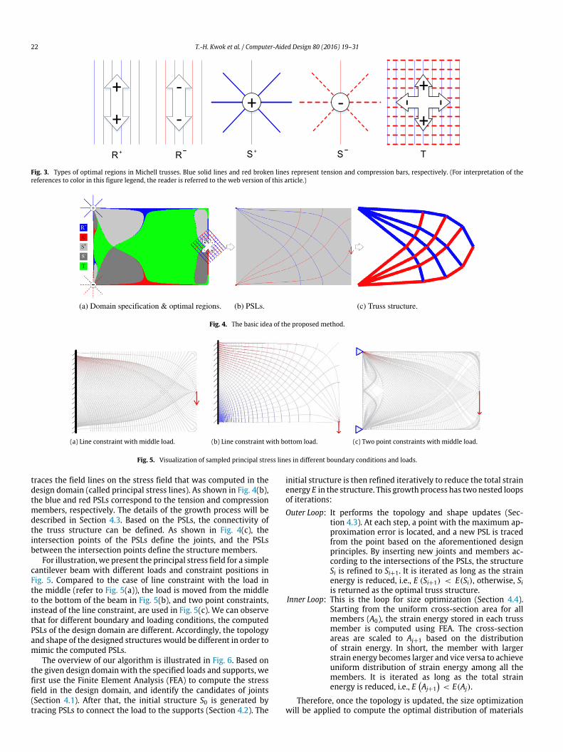
where ε1 and ε2 are the principal adjoint strains, and f1 and f2 arethe corresponding member forces. The layouts of various types ofoptimal regions, together with their commonly used symbols, areshown in Fig. 3.
As can be seen, members run in only one direction in R regions,and the forces have the same sign. In S regions, members with theforces of a given sign may run in any direction. The compressionand tension members in the T region are orthogonal to each other.For the classical Michell problem, Rozvany [40] stated that ‘‘Ifa pair of tension and compression members cross each other, theymust be orthogonal... No other members can be coplanar with them’’.Therefore, as the T region is the only region that can fulfill theorthogonality requirement, a subdivision should always happenin the T region. In the rest of the paper, for the points in theR+, R−, S+, S−, T regions, we call them R+, R−, S+, S−,T -points respectively. After doing the stress–strain analysis on thedesign domain with the given load and boundary conditions, thetype of a point can be determined by computing the memberforces (f1, f2) of that point along the principal directions, and thenmatching them with the optimality criteria listed in Eq. (2). Inpractice, we replace f2 = 0 by |f2| < δ to address the numericalerrors in computation, and we set δ =
f11000 .
3.2. Algorithm overview
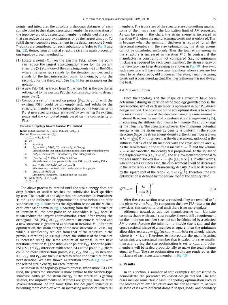
The development of our topology design framework is based onthe aforementioned principles. The basic idea of the algorithm isas follows. Through the stress and related optimal region analysis,we can know the structural pattern of the local region aroundthe load and the supports. For the example of the classic case ofthe single-load and two-supports cantilever as shown in Fig. 4,after the analysis of the optimal regions, we know that the loadingpoint is a T -point and the two fixed supports are S+-point andS−-point, respectively. Therefore, a pair of orthogonal compressionand tension members should meet at the point of loading, while aset of tension/compression members should end at the points ofsupport (see Fig. 4(a)). After knowing the local structural patterns,the next step is to find out how they are connected. Our approach
22 T.-H. Kwok et al. / Computer-Aided Design 80 (2016) 19–31
Fig. 3. Types of optimal regions in Michell trusses. Blue solid lines and red broken lines represent tension and compression bars, respectively. (For interpretation of thereferences to color in this figure legend, the reader is referred to the web version of this article.)
(a) Domain specification & optimal regions. (b) PSLs. (c) Truss structure.
Fig. 4. The basic idea of the proposed method.
(a) Line constraint with middle load. (b) Line constraint with bottom load. (c) Two point constraints with middle load.
Fig. 5. Visualization of sampled principal stress lines in different boundary conditions and loads.
traces the field lines on the stress field that was computed in thedesign domain (called principal stress lines). As shown in Fig. 4(b),the blue and red PSLs correspond to the tension and compressionmembers, respectively. The details of the growth process will bedescribed in Section 4.3. Based on the PSLs, the connectivity ofthe truss structure can be defined. As shown in Fig. 4(c), theintersection points of the PSLs define the joints, and the PSLsbetween the intersection points define the structure members.
For illustration, we present the principal stress field for a simplecantilever beam with different loads and constraint positions inFig. 5. Compared to the case of line constraint with the load inthe middle (refer to Fig. 5(a)), the load is moved from the middleto the bottom of the beam in Fig. 5(b), and two point constraints,instead of the line constraint, are used in Fig. 5(c). We can observethat for different boundary and loading conditions, the computedPSLs of the design domain are different. Accordingly, the topologyand shape of the designed structures would be different in order tomimic the computed PSLs.
The overview of our algorithm is illustrated in Fig. 6. Based onthe given design domain with the specified loads and supports, wefirst use the Finite Element Analysis (FEA) to compute the stressfield in the design domain, and identify the candidates of joints(Section 4.1). After that, the initial structure S0 is generated bytracing PSLs to connect the load to the supports (Section 4.2). The
initial structure is then refined iteratively to reduce the total strainenergy E in the structure. This growth process has two nested loopsof iterations:Outer Loop: It performs the topology and shape updates (Sec-
tion 4.3). At each step, a point with the maximum ap-proximation error is located, and a new PSL is tracedfrom the point based on the aforementioned designprinciples. By inserting new joints and members ac-cording to the intersections of the PSLs, the structureSi is refined to Si+1. It is iterated as long as the strainenergy is reduced, i.e., E (Si+1) < E(Si), otherwise, Siis returned as the optimal truss structure.
Inner Loop: This is the loop for size optimization (Section 4.4).Starting from the uniform cross-section area for allmembers (A0), the strain energy stored in each trussmember is computed using FEA. The cross-sectionareas are scaled to Aj+1 based on the distributionof strain energy. In short, the member with largerstrain energy becomes larger and vice versa to achieveuniform distribution of strain energy among all themembers. It is iterated as long as the total strainenergy is reduced, i.e., E
Aj+1
< E(Aj).
Therefore, once the topology is updated, the size optimizationwill be applied to compute the optimal distribution of materials

T.-H. Kwok et al. / Computer-Aided Design 80 (2016) 19–31 23
Fig. 6. The flowchart of the algorithm overview. E(·) represents the strain energy.
based on the updated topology. The optimized energy is comparedwith the energy in the previous step, and the iterations are stoppedwhen no more improvement is made. Each step is discussed indetail in the following section.
4. Design framework
4.1. Domain specification
Given a design domainΩ ∈ R2 with given load f and supportφ.We first use the stress analysis method based on FEA to compute astress fieldFσ inΩ . Specifically, a finite elementmesh (e.g., quadri-lateralmesh) is generated forΩ , and the load and support are spec-ified as the nodal forces and boundary conditions applied to thenodes of the mesh. Approximations for the strain and stress followdirectly from the displacements:
ε = Lu = LNjuj ≡ Bjuj, (3)
σ = Dε = DBjuj, (4)
where u is the set of the nodal displacements, L is the matrix ofdifferential operators, Nj are the shape functions, Bj = LNj, and theHooke’s law takes the plane stress condition. An increase in strainenergy δU in an element with a force fi applied on node i is givenby:
δU =
V
δεTσdV = δuTi
VBTi DBjdV uj, (5)
which must be equal to the work done by the nodal forces:
δW = δuTi fi. (6)
Equating Eqs. (5) and (6), and canceling the common factor δuTi re-
sults inVBTi DBjdV
uj = fi. (7)
This is of the desired form Ku = F with the stiffness matrixK =
kij
, and kij =
V BT
i DBjdV . The result can be generated by
a FEA system (e.g., COMSOL). In our study, we have implementedthe FEA in our PSL-based design system for a better integration. TheFEA results have been verified by the commercial system; however,our FEA code has not been optimized for the best efficiency. For anypoint p ∈ Ω , its stress tensor is defined by Fσ as σx, σy, τxy. Theprincipal stresses are the components of the stress tensor whenthe basis is changed such that the shear stress components becomezero. The angle between such a basis and the x-axis is given by
θ =12tan−1
2τxy
σx − σy
, (8)
and the principal stresses are
σ1,2 =σx + σy
2±
σx − σy
2
2
+ τ 2xy. (9)
This stress field Fσ is a physical representation that containsthe information about the relationship between the load f and thesupportsφ. Therefore, it is also the governing field thatwill be usedfor generating the truss structure of the given design problem. Asthe principal directions are defined for thewhole design domainΩ ,PSLs can be traced starting from any point in the domain. Withoutloss of generality, assume a PSL is being traced froma starting pointp0 in the principal direction v0. We use an incremental method bymoving a small step δ along the current principal direction, i.e.,pi = pi−1+δ·vi−1, and computing theprincipal direction in thenewposition for the next iteration. As there are two principal directionsat each point, the one closer to vi−1 will be selected as vi. In ourtests, we use δ = 0.001 m.
We identify the candidates of joint points in this step. Thereare four types of candidate joints, including: (1) the point ofloading, (2) the points of supports, (3) local maximal points, and(4) intersection points. Because the goal of the structure is towithstand the loads through the supports, it is obvious that the firsttwo types of joints have to be in the designed structure. The thirdtype is the localmaximal point that is a point having themaximumprincipal stress value in its neighboring region. It can be locatedby checking whether its absolute stress value is greater than itsneighbors’ stress values. Generally speaking, the maximal pointsare the points with loads and supports. However, as the designspace is limited by the given design domainΩ , some localmaximalpoints may be located on the boundary ∂Ω . For the example ofthe L-shape domain as shown in Fig. 7, the upper corner at theturning point of ‘‘L’’ is a local maximal point. It will be one of thejoints in the final structure. This type of joint is generally a S+-pointor S−-point, where both member forces have the same sign (referto Fig. 3 and Eq. (2)). Finally, the joints of the fourth type arethe intersections between PSLs, as the structure members canonly cross each other through joints. Notice that, the first threetypes of joints are identified as candidates in this step. They areactivated and constructed only when a PSL reaches them. Theintersection points are created whenever an intersection betweenPSLs happens.
4.2. Initial structure
The goal of the initial structure is to connect the loads to thesupports. Automatically constructing an initial structure for a givenproblem is difficult. Onemay solve the problembydirectly creatinga set of straight bars between the load and the supports, and theneliminating the zero-volume ones during the size optimization.Although this method works well on the Michell cantileverproblem, it does notwork formore complicated cases. For instance,directly connecting the load and supports in the concave L-shapedomain shown in Fig. 7 will result in a structure outside the designdomain; directly connecting the load and supports in the bridge

24 T.-H. Kwok et al. / Computer-Aided Design 80 (2016) 19–31
(a) L- shape design domain. (b) Stress field. (c) Initial PSLs.
(d) Initial structure.
Fig. 7. (a) The input L-shape design domain with specified load and supports. (b) The stress field computed on the domain, and the candidate joints are identified. (c) InitialPSLs are constructed by tracing from the points of load to the points of support. (d) The initial structure is constructed based on the connectivity and the intersections ofPSLs.
(a) Bridge design domain. (b) Initial PSLs. (c) Initial structure.
Fig. 8. The bridge problem and its initial structure generated by our method.
structure shown in Fig. 8will create twohorizontal bars, whichwillmake it difficult to do further subdivision. Therefore, the previousgrowth-based methods generally required user interaction whencreating the initial structure.
In our method, the PSLs describe how the load is connected tothe supports within the design domain, and we can generate theinitial structure automatically with the help of the PSLs. Specifi-cally, our method consists of three phases to compute the connec-tivity including (I) load phase, (II) local maximal point phase, and(III) support phase.Load Phase (I)
Although there could be multiple supports, not all of themwould connect to the loads. The goal of the load phase is toconnect the loads to some of the given supports that can providethe best performance. Therefore, the first phase in computing theinitial structure is to trace PSLs starting from the loading point(Ref. Section 4.1). If the PSLs end at some points of support (e.g., theMichell cantilever in Fig. 4, or Ib in Fig. 7), a structural memberis created for each of these PSLs, in which the two endpoints arethe points of load and support. Otherwise, if a PSL ends at a localmaximal point (e.g., Ia in Fig. 7), the point is activated and a joint iscreated at that position. Afterwards it goes to Phase II.Local Maximal Point Phase (II)
This phase is performed only if there is at least one localmaximal point that is activated in Phase I. A set of PSLs is tracedfrom the activated points. For the example shown in Fig. 7, theupper PSL (IIa) ends at a point of support, and a structural memberis created between them. Another PSL (IIb) going toward the leftintersects an existing PSL (Ib), and thus Ib is subdividedwith a jointcreated at the intersection point. A structural member is createdbetween the intersection point and the localmaximal point aswell.The resultant initial structure is shown in Fig. 7(d). The PSLs that do
not have any intersection with others or will create duplicates ofstructural member are discarded automatically.Support Phase (III)
When the loading and supporting points are collinear (e.g. inthe example of bridge as shown in Fig. 8), they are connected byintersection points that are created in the support phase. That is,we trace PSLs from the supporting points to intersect the PSLs thatare traced in Phase I. In Phase III, we create a queue to sort thesupporting points in a descending order in term of their stressvalues. Each time, the point with the maximum stress value istaken out from the queue and PSLs are traced from it. This processis continued until there is an intersection between the tracedPSLs and the existing ones. The initial structure generated by ourmethod for the bridge problem is shown in Fig. 8(c).
More test results will be shown in Section 5. The presentedPSLs-based initial structure generation method was used in all ofthe test cases.
4.3. Topology growth
The PSLs play an important role not only in the initial structuregeneration, but also in the topology growth process. The traditionalshape and topology optimization is a non-linear problem. Withthe help of PSLs, we convert the shape and topology optimizationinto a geometric design problem. Based on design principle 1,the goal of the topology growth is to refine the structure tobetter mimic the shape of the computed PSLs. In other words,the approximation errors between the structure and the PSLs inthe design domain need to be minimized. Such approximationerror in our study is calculated as the area of the region that isbounded by them (refer to Fig. 9). The area is computed by anumerical method that uniformly samples the PSL into a set of
T.-H. Kwok et al. / Computer-Aided Design 80 (2016) 19–31 25
points, and integrates the absolute orthogonal distances of eachsample point to the related structural member. In each iteration ofthe topology growth, a structural member is subdivided at a pointthat can reduce the approximation error by the largest amount. Tofulfill the orthogonality requirement in the design principle 3, onlyT -points are considered for such subdivisions (refer to Fig. 3 andEq. (2)). Hence, from an initial structure (S0), the main process ofour topology growth method is:
(1) Locate a point (Pi,a) on the existing PSLs, where the pointcan reduce the largest approximation error for the currentstructure (Si). Pi,a is one of the sampling points Pk on the PSLs,where the subscript i stands for the iteration number, and astands for the first intersection point (following by b for thesecond, c for the third, etc.). See Fig. 10 for an example on thenotation.
(2) A new PSL (PSLi) is traced from Pi,a, where PSLi is the one that isorthogonal to the existing PSL that contains Pi,a (refer to designprinciple 2).
(3) Compute a set of intersection pointsPi,b, Pi,c, . . .
with the
existing PSLs (could be an empty set), and subdivide thestructural members by the intersection points together withPi,a. A new structure (Si+1) is created by connecting the existingjoints and the computed joints based on the connectivity ofPSLs.
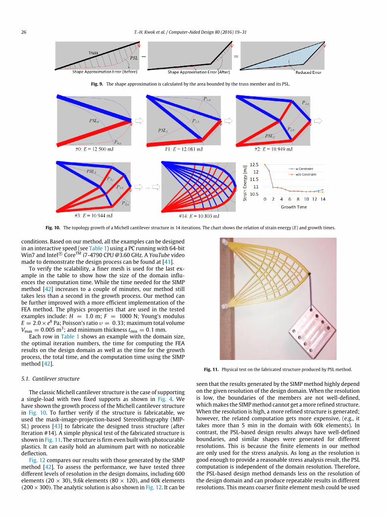
The above process is iterated until the strain energy does notdrop further, or until it reaches the subdivision level specifiedby user. The details of the algorithm are described in Procedure1; A is the difference of approximation error before and aftersubdivision. Fig. 10 illustrates the algorithm based on the Michellcantilever case shown in Fig. 4. Starting from the initial structurein iteration #0, the best point to be subdivided is P0,a, becauseit can reduce the largest approximation error. After tracing theorthogonal PSL (PSL0) of P0,a, the overall structure is refined anda new structure is generated as shown in iteration #1. After sizeoptimization, the strain energy of the new structure is 12.081 mJ,which is significantly reduced from that of the structure in theprevious iteration (12.500mJ). Hence, the stiffness of the structureis increased using the same amount of material. In the nextiteration (iteration#1), the subdivisionpoint is P1,a. The orthogonalPSL (PSL1) of P1,a intersects with other PSLs at the point P1,b (therecould be more intersection points, e.g., P3,b and P3,c in iteration#3). P1,a and P1,b are then inserted to refine the structure for thenext iteration. We have shown 14 iteration steps in Fig. 10 withthe related strain energy for each iteration.
As shown in the topology growth process, when more PSLs areused, the generated structure is more similar to the Michell-typestructure. Although the strain energy of the structure is gettingsmaller, the improvements on stiffness are getting smaller afterseveral iterations. At the same time, the designed structure isbecoming more complex with an increasing number of structural
members. The truss sizes of the structure are also getting smaller;some of them may reach the fabrication limit of AM processes.As can be seen in the chart, the strain energy is increased initeration #13 when the manufacturing constraint is enforced. Thisis because when the minimum thickness is required for all thestructural members in the size optimization, the strain energycannot be distributed uniformly. Thus the total strain energy inthe structure is increased in iteration #13. In contrast, if themanufacturing constraint is not considered (i.e., no minimumthickness is required for each truss member), the strain energy ofthe structure can keep decreasing as shown in Fig. 10. However,such structure will have structural members whose sizes are toosmall to be fabricated byAMprocesses. Therefore, ifmanufacturingconstraint is considered, getting the finest refinement is not alwaysthe best.
4.4. Size optimization
Once the topology and the shape of a structure have beendetermined during an iteration of the topology growth process, thecross-section size of each member is optimized in our PSL-baseddesign method. The objective of the size optimization is to achievethe maximum stiffness of the structure using the same amount ofmaterial. Based on themethod of uniform strain energy density [5],maximizing the stiffness also means to minimize the strain energyof the structure. The structure achieves the minimum potentialenergy when the strain energy density is uniform in the entirestructure. Since the strain energy density of the ithmember is givenasUi =
12Vi
uTi Ki(xi)ui, where ui is the displacement, and Ki(xi) is the
stiffness matrix of the ith member with the cross-section area xi.As the area factors in the stiffness matrix K =
ExL and the volume
V = xL are cancelled, the density U is proportional to the square ofthe displacement u (i.e., U ∝ u2), and u is inversely proportional tothe area under Hooke’s law: F =
ExL u (i.e., u ∝
1x ). In other words,
when the area x is increased, the displacement uwill be decreasedin the same ratio, and the strain energy densityU will be decreasedby the square root of the ratio (i.e., x ∝ ( 1
U )12 ). Therefore, the size
optimization is defined by the square root of the density ratio:
xnewi = xi ·
Ui
maxj
Uj
12
. (10)
After the cross-section areas are resized, they are rescaled to fitthe given volume Vmax. By computing the new FEA results on thenew sizes, this step is iterated until there is no more update.
Although nowadays additive manufacturing can fabricatecomplex shape with small cost penalty, there is still a requirementon the minimummember size that can be fabricated by a selectedAM process. Assume the minimum printable size is tmin, and thecross-sectional shape of a member is square, then the minimumallowable size is xmin = t2min (or xmin = tmin·h for rectangular shape,where h ≥ tmin). Therefore, to incorporate the manufacturingconstraint, any structural member that is scaled to a size smallerthan xmin during the size optimization is set to xmin, and othermembers will be scaled proportionally to make the total volumeequal to Vmax. The size optimization results are rendered as thethickness of each structural member in Fig. 10.
5. Results
In this section, a number of test examples are presented todemonstrate the presented PSL-based design method. The testcases include some classic cases in topology optimization such asthe Michell cantilever structure and the bridge structure, as wellas some cases with different domain shapes, loads, and boundary
26 T.-H. Kwok et al. / Computer-Aided Design 80 (2016) 19–31
Fig. 9. The shape approximation is calculated by the area bounded by the truss member and its PSL.
Fig. 10. The topology growth of a Michell cantilever structure in 14 iterations. The chart shows the relation of strain energy (E) and growth times.
conditions. Based on ourmethod, all the examples can be designedin an interactive speed (see Table 1) using a PC running with 64-bitWin7 and Intel R⃝ CoreTM i7-4790 CPU @3.60 GHz. A YouTube videomade to demonstrate the design process can be found at [41].
To verify the scalability, a finer mesh is used for the last ex-ample in the table to show how the size of the domain influ-ences the computation time. While the time needed for the SIMPmethod [42] increases to a couple of minutes, our method stilltakes less than a second in the growth process. Our method canbe further improved with a more efficient implementation of theFEA method. The physics properties that are used in the testedexamples include: H = 1.0 m; F = 1000 N; Young’s modulusE = 2.0× e8 Pa; Poisson’s ratio υ = 0.33; maximum total volumeVmax = 0.005 m3; and minimum thickness tmin = 0.1 mm.
Each row in Table 1 shows an example with the domain size,the optimal iteration numbers, the time for computing the FEAresults on the design domain as well as the time for the growthprocess, the total time, and the computation time using the SIMPmethod [42].
5.1. Cantilever structure
The classicMichell cantilever structure is the case of supportinga single-load with two fixed supports as shown in Fig. 4. Wehave shown the growth process of the Michell cantilever structurein Fig. 10. To further verify if the structure is fabricatable, weused the mask-image-projection-based Stereolithography (MIP-SL) process [43] to fabricate the designed truss structure (afterIteration #14). A simple physical test of the fabricated structure isshown in Fig. 11. The structure is firm even built with photocurableplastics. It can easily hold an aluminum part with no noticeabledeflection.
Fig. 12 compares our results with those generated by the SIMPmethod [42]. To assess the performance, we have tested threedifferent levels of resolution in the design domains, including 600elements (20 × 30), 9.6k elements (80 × 120), and 60k elements(200×300). The analytic solution is also shown in Fig. 12. It can be
Fig. 11. Physical test on the fabricated structure produced by PSL method.
seen that the results generated by the SIMPmethod highly dependon the given resolution of the design domain. When the resolutionis low, the boundaries of the members are not well-defined,whichmakes the SIMPmethod cannot get amore refined structure.When the resolution is high, a more refined structure is generated;however, the related computation gets more expensive, (e.g., ittakes more than 5 min in the domain with 60k elements). Incontrast, the PSL-based design results always have well-definedboundaries, and similar shapes were generated for differentresolutions. This is because the finite elements in our methodare only used for the stress analysis. As long as the resolution isgood enough to provide a reasonable stress analysis result, the PSLcomputation is independent of the domain resolution. Therefore,the PSL-based design method demands less on the resolution ofthe design domain and can produce repeatable results in differentresolutions. This means coarser finite element mesh could be used

T.-H. Kwok et al. / Computer-Aided Design 80 (2016) 19–31 27
Table 1Time statistics and comparison.
Example Domain size Iter. FEA (s) Growth (s) Total (s) SIMP [42] (s)
Fig. 10 9600 (80 × 120) 10 1.490 0.168 1.658 38.39Fig. 13 9600 (80 × 120) 6 1.513 0.156 1.669 26.03Fig. 14 5000 (50 × 100) 8 0.900 0.055 0.955 12.67Fig. 16 6400 6 1.076 0.440 1.516 70.57Fig. 17 40000 (200 × 200) 6 6.531 0.549 7.080 218.64
Fig. 12. A comparison between the results of cantilever structure generated by the SIMPmethod and the PSL-basedmethodwith different resolutions of the design domain.The analytic optimum is shown on the left, and the total time to generate the structures are shown in the bottom-right for each of them accordingly.
Fig. 13. The test case of an asymmetric cantilever structure. (For interpretation of the references to color in this figure legend, the reader is referred to the web version ofthis article.)
in the PSL-based design method for shorter computation time.Furthermore, even in the domain with 60k elements, our methodtakes less than 10 s in total to complete all the steps, in whichthe FEA takes 9.2 s and the growth process takes only 0.36 s. Thisis promising for some complicated cases or 3D problems that aremore computationally intensive. More importantly, our methodcan generate results with different refinement levels to mimicthe analytic solution of the Michell truss, and the user can havethe explicit control on which level of refinement to stop. Suchcapability is not supported by the SIMP method.
Beside the symmetric cantilever structure, we have also testedthe asymmetric one as shown in Fig. 13. In this example, thedesign domain is exactly the same as the symmetric one; however,the load is applied on the bottom-right corner instead of the
middle of the right edge. To compare with the symmetric case, thedomain specification and the optimal regions indicated by Eq. (2)have also been shown. The R+, R−, S+, S−, and T regions areshown in blue, red, light gray, gray, and green, respectively. Thesubdivisions are allowed only in the T regions. Notice that, theoptimal regions are visualized based on the sampling in the designdomain, which is just for reference. The sampling is not neededin the computation for topology growth; instead, the principalstrains can be directly computed from the FEA result for any pointsin the domain. Therefore, some subdivision points (e.g., P3,a inFig. 13) may look like outside the T -region, but they actually areT -points. In both of the symmetric and asymmetric cases, the initialstructures have two structural members and three joints. Afterthe growth process, the strain energy is decreased from 15.125 to

28 T.-H. Kwok et al. / Computer-Aided Design 80 (2016) 19–31
Fig. 14. The topology growth of a bridge structure.
Fig. 15. A comparison between the results of bridge structure generated by the SIMPmethod and the PSL-basedmethod based on different resolutions of the design domain.The analytic optimum is shown on the left, and the total time to generate the related structures are shown in the top-right of each structure.
12.376 mJ. Hence, the stiffness of the structure is increased usingthe same amount ofmaterial in the structure. It can be seen that thePSL-based method can work for both symmetric and asymmetriccases without modifications to the design method or the userinterface.
5.2. A bridge structure
The design domain and the initial structure of a bridge designproblem are shown in Fig. 8. The initial structure has three mem-bers and four joints. The optimal regions and the related topol-ogy growth process are shown in Fig. 14. After eight iterations, thestrain energy of the designed structure has been decreased from4.161 to 3.588 mJ.
A comparison between our method and the SIMP method forthe bridge structure is shown in Fig. 15. Again, three different levelsof resolution, 800 elements (20 × 40), 20k elements (100 × 200),and 80k elements (200× 400), were used. The analytic solution ofthe structure is also shown in Fig. 15. A similar phenomenon canbe found, that is, the quality and the computational effort of theSIMPmethod depend heavily on the given resolution of the designdomain, while our method generates similar results in differentresolutions. In the domain with 80k elements, the SIMP methodtakes about 8min,while ourmethod takes 12.66 s, inwhich the FEAtakes 12.33 s and the growth process takes only 0.34 s. In addition,the results generated by our method can better mimic the shapedefined by the analytic solution of the Michell truss than thosegenerated by the SIMP method.
5.3. L-shaped design domain
A test case with different design domain is the L-shape designproblem as shown in Fig. 7. The domain is fixed at two points onthe top, and a load is applied on the bottom-right of the ‘‘L’’. In this
example, H = 2.0 m. Fig. 16 shows its growth process using thePSL-based design method. The test case has six iterations, and thestrain energy is decreased from 139.557 to 84.206 mJ. The resultgenerated by the SIMP method is also shown in the figure for acomparison.
Instead of the L-shape domain, we have also tested our designmethod based on a convex design domain. All other conditionsare exactly the same as the ‘‘L’’ domain test case. As shown inthe bottom row of Fig. 17, the growth process for this structure isconverged in six steps to achieve the strain energy of 14.633 mJ,which is much lower than that of the L-shape domain. In thisexample, we can see that the given design domain affects thecomputed final structure, and our proposed framework can handleboth concave and convex domains without any modifications tothe design method.
5.4. Bicycle frame structure
Fig. 18 shows a test case using a bicycle frame structure [44].The given load simulates the situation of a person sitting on theframe and holding the front handles. Therefore, two loads, one inthe middle pointing down and one on the left with both x and ydirections, are applied. The domain is fixed at two points on thebottom to simulate the centers of the wheels. After performing theFEA on the design domain, the optimal regions can be computedfor the design problem. The two points of load are T -point andS−-point, and the two points of support are S+- and S−-points,respectively. There is one local maximum point at the top of thedomain between two points of load. PSLs were traced from thetwo points of load consecutively in the load phase during theinitial structure generation. Accordingly, the connectivity betweenthe loads and supports was found. The initial structure has sixmembers and five joints. The growth process is converged infive iterations, and the strain energy is decreased from 12.916 to10.167 mJ.

T.-H. Kwok et al. / Computer-Aided Design 80 (2016) 19–31 29
Fig. 16. The topology growth of a concave L-shaped structure using the PSL method, compared with the result generated by SIMP method.
Fig. 17. The example of a convex L-shaped structure.
Fig. 18. The topology growth of a bicycle frame structure.
6. Conclusions and discussion
Based on the principle of minimum shear stress in the Michell-type structure and the proposition of uniform strain energy den-sity in discrete truss structures, we presented a new structuraltopology design framework that is computationally fast and easy tocontrol. Three design principles are derived from theMichell’s the-orem. The principal stress lines are used to identify the topol-ogy and shape of the designed structure. The PSL-based topologygrowth process is to reduce the difference between the generated
structure and the PSLs computed in the design domain. The fabri-cation constraints given by additivemanufacturing processes havebeen incorporated in the structure design process. With a givenminimum fabrication size, the refinement of the structure needsto be controlled; the finest refinement may not lead to the optimalstructure. An algorithmwith the topology growth as the outer loopand the size optimization as the inner loop has been developedto control the optimal refinement level. A number of exampleshave been used to test the PSL-based design method. The resultshave demonstrated its effectiveness and efficiency. In addition, the

30 T.-H. Kwok et al. / Computer-Aided Design 80 (2016) 19–31
Fig. 19. A test case showing the growth process of 3D cantilever structure design by PSL strategy.
PSL-based method is general. The same design process and userinterface can be used for symmetric and asymmetric cases, con-vex and concave domains, as well as single and multiple externalforces.
Webelieve the PSL-based designmethod is promising for devel-oping practical designing tools for various structural applications.The presented principles can be extended to three-dimensional(3D) problems. A simple test example of a 3D cantilever is shownin Fig. 19, which illustrates how the PSLs in a 3D design domaincould be used for designing a 3D cantilever. The PSL distributionin the 3D design domain is visualized in the figure. Two iterationsof topology growth are performed. The strain energy of the struc-ture in iteration #2 is smaller than that in iteration #0. Hence, thestructure is getting stiffer with the same amount of material. How-ever, the load paths based on the principal stresses in the 3D casesare more complicated. In addition, the PSLs in some regions couldbecome messy. Another challenge of using the PSL-based methodin 3D domain is how the intersections between different PSLs canbe robustly computed in order to use them in the topology growthstep. Our future work will study how these issues can be handled.
In addition to addressing 3D problems, the PSL-based designmethod still has a number of limitations that need to be addressed.Firstly, as our design principles are developed based on Michell’stheorem in minimizing compliance, the current version is notable to handle other design goals. In the future, we will studyother theorems (e.g., the optimality criteria advocated by Praeger,Rozvany) to see if the related mathematical problems can beconverted into geometric design problems. Secondly, we onlyconsider the point loads in this paper. For a structure that needsto support a distributed volume load, further research is neededon how it will affect the tracing of PSLs. Thirdly, we assume thetruss structure has the same strengths in tension and compression.If such strengths are different, the structure should have differenttopology and shape. One way to incorporate such strengthdifference is to add weights to the approximation errors betweenthe structure and the PSLs. Our future work will study how toincorporate the allowable tension and compression strains aswell.
Acknowledgments
This work is partially supported by the James H. ZumbergeFaculty Research and Innovation Fund at the USC, and the NationalScience Foundation grant IIP-0810637.
References
[1] Gao W, Zhang Y, Ramanujan D, Ramani K, Chen Y, Williams CB, Wang CCL,Shin YC, Zhang S, Zavattieri PD. The status, challenges, and future of additivemanufacturing in engineering. Comput-Aided Des 2015;69:65–89.
[2] EOS and Airbus Group Innovations Team on Aerospace Sustainability Studyfor Industrial 3D Printing, EOS, 5 Feb 2014. [Online]. Available: http://www.eos.info/eos_airbusgroupinnovationteam_aerospace_sustainability_study.W460W9435.
[3] Michell AGM. The limit of economy of material in frame structures. Phil Mag1904;8(47):589–97.
[4] Tomasz S. A 99 line code for discretized Michell truss optimization written inMathematica. Struct Multidiscip Optim 2011;43(2):181–90.
[5] Rozvany GIN. Topology optimization in structural mechanics. New York:Springer; 1997.
[6] Bendsøe MP, Sigmund O. Topology optimization: theory, methods, andapplications. Berlin (Heidelberg): Springer; 2004.
[7] Kirsch U. Optimal topologies of truss structures. Comput Methods Appl MechEngrg 1989;72(1):15–28.
[8] Bendsøe MP, Mota Soares CA, editors. Topology design of structures.Netherlands: Springer; 1993.
[9] Rozvany GIN, Bendsøe MP, Kirsch U. Layout optimization of structures. ApplMech Rev 1995;48(2):41–119.
[10] Bendsoe MP, Sigmund O. Topology optimization: theory, methods, andapplications. Berlin: Springer; 2003.
[11] Dorn WS, Gomory RE, Greenberg HJ. Automatic design of optimal structures.J. Mec. 1964;3:25–52.
[12] Hemp WS. Studies in the theory of Michell structures. In: Internationalcongress of applied mechanics. Munich, West Germany, 1964. W460W9435.
[13] Hemp WS. Optimum structures. Oxford (United Kingdom): Clarendon Press;1973.
[14] Hemp WS, Chan HSY. Optimum design of pin-jointed frameworks, London,United Kingdom: Aeronautical Research Council Reports and Mem. No. 3632.Her Majesty’s Stationery Office; 1970.
[15] Haug EJ, Arora JS. Applied optimal design. New York: Wiley & Sons; 1979.[16] Bendsøe MP. Methods for optimization of structural topology, shape and
material. Verlag (New York): Springer; 1995.[17] Achtziger W, Bendsøe MP, Ben-Tal A, Zowe J. Equivalent displacement based
formulations formaximum strength truss topology design. Impact Comput SciEng 1992;4:315–45.
[18] Svanberg K. Optimal truss sizing based on explicit Taylor series expansions.Struct Multidiscip Optim 1990;2:153–62.
[19] Svanberg K. Global convergence of the stress ratio method for truss sizing.Struct Multidiscip Optim 1994;8:60–8.
[20] Taylor JE. Maximum strength elastic structural design, proceedings of theASCE. J Eng Mech Div 1969;95:653–63.
[21] Taylor JE, Rossow MP. Optimal truss design based on an algorithm usingoptimality criteria. Internat J Solids Structures 1977;13:913–23.
[22] Bendsøe MP, Ben-Tal A. Truss topology optimization by a displacement basedoptimality criterion approach. Optim. Large Struct. Syst. 1993;I:139–55.
[23] Achtziger W, Stolpe M. Global optimization of truss topology with discretebar areas - Part I: Theory of relaxed problems. Comput Optim Appl 2008;40:247–80.

T.-H. Kwok et al. / Computer-Aided Design 80 (2016) 19–31 31
[24] Achtziger W, Stolpe M. Global optimization of truss topology with discretebar areas - Part II: Implementation and numerical results. Comput Optim Appl2009;44:315–41.
[25] Xie YM, Steven GP. Evolutionary structural optimization. New York: Springer;1997.
[26] Achtziger W. On simultaneous optimization of truss geometry and topology.Struct Multidiscip Optim 2007;33:285–304.
[27] Scott AB. Recent advances in optimal structural design. Reston (VA): Instituteof the American Society of Civil Engineers; 2002.
[28] Rule WK. Automatic truss design by optimized growth. J Struct Eng 1994;120(12):3063–70.
[29] Shea K, Cagan J, Fenves SJ. A shape annealing approach to optimal truss designwith dynamic grouping of members. J Mech Des 1997;119(3):388–94.
[30] Shea K, Cagan J. Innovative dome design: Applying geodesic patterns withshape annealing. Artif Intell Eng Des Anal Manuf 1997;11(5):379–94.
[31] McKeown JJ. Growing optimal pin-jointed frames. Struct Optim 1998;15(2):92–100.
[32] Bojczuk D, Mróz Z. Optimal topology and configuration design of trusses withstress and buckling constraints. Struct Optim 1999;17(1):25–35.
[33] Gilbert M, Tyas A. Layout optimization of large-scale pin-jointed frames. EngComput 2003;20(8):1044–64.
[34] SokółT. Topology optimization of large-scale trusses using ground structureapproach with selective subsets of active bars. In: 19th internationalconference on computer methods in mechanics. Warsaw, Poland. 2011.W460W9435.
[35] Sokół T. A 99 line code for discretized Michell truss optimization written inMathematica. Struct Multidiscip Optim 2011;43(2):181–90.
[36] SokółT, Rozvany GIN. On the adaptive ground structure approach for multi-load truss topology optimization. In: 10th world congress on structural andmultidisciplinary optimization. Orlando, Florida. 2013. W460W9435.
[37] Martínez P, Martí P, Querin OM. Growth method for size, topology, andgeometry optimization of truss structures. Struct Multidiscip Optim 2007;33(1):13–26.
[38] Ning X, Pellegrino S. Design of lightweight structural components fordirect digital manufacturing. In: 53rd AIAA/ASME/ASCE/AHS/ASC structures,structural dynamics and materials conference. Honolulu, Hawaii, 2012.W460W9435.
[39] Rozvany GIN. Structural topology optimization (STO) – exact analyticalsolutions: Part I. In: Topology optimization in structural and continuummechanics. Vienna: Springer; 2014. p. 1–14.
[40] Rozvany GIN. Partial relaxation of the orthogonality requirement for classicalMichell trusses. Struct Optim 1997;13(4):271–4.
[41] Kwok T, Li Y, Chen Y. A topology design method for 3D printing, 2015.[Online]. Available: https://www.youtube.com/watch?v=Sd7Y2OQ1umA [Ac-cessed 15.06.15]. W460W9435.
[42] Andreassen E, Clausen A, Schevenels M, Lazarov BS, Sigmund O. Efficienttopology optimization in MATLAB using 88 lines of code. Struct MultidiscipOptim 2011;43(1):1–16.
[43] Pan Y, Zhou C, Chen Y. A fast mask projection stereolithography process forfabricating digital models in minutes. ASME J Manuf Sci Eng 2012;134(5):051011.
[44] Suppapitnarm A, Parks GT, Shea K, Clarkson PJ. Conceptual design of bicycleframes by multiobjective shape annealing. Eng Optim 2004;36(2):165–88.