the widening of los santos bridge. a case study of a ... · ariel espeche . fhecor j ingenieros...
TRANSCRIPT
F H E C O R Ingenieros Consultores
Página 1 Barquillo, 23 2º | 28004 MADRID | Tel 91 701 44 60 | Fax 91 532 78 64 [email protected] | www.fhecor.es
ABSTRACT In this paper the main features of the Construction project of the widening of Los Santos Bridge are discussed. The project involves the widening of a major 600 m long bridge with spans of 150 meters increasing the width of the deck from 12.00 to 24.00 meters, without recurring to an independent structure. The project is based on the idea of providing minimum strengthening of the existing structure. This approach has allowed very important savings but has also required a challenging design project some aspects of which are discussed in this paper. 1. INTRODUCTION Los Santos Bridge is a five span structure located in the North of Spain at the border line between the Autonomous Communities of Galicia and Asturias. The bridge, with a total length of 600 m and spans of 150 m, was built by cantilever construction at the beginning of the 1980’s. It is currently being refurbished in order to duplicate its capacity. One of the great difficulties of the project and its construction is that traffic must be maintained at all times. When the duplication of the bridge was studied by FHECOR Consulting Engineers, the conclusion was reached that it was possible to use the current structure with local reinforcement of foundations and external prestressing as well as additional reinforcement of the deck using a superimposed steel structure. This solution was found to be significantly cheaper in terms of material costs than previous proposals based on building an independent structure. Although the original structure was very tight in terms of provided reinforcement, possibly a consequence of the troubled economic times in which it was built, it was found possible to accommodate
The Widening of Los Santos Bridge. A Case Study of a
Tailor-made Structure.
Hugo Corres Peiretti José Romo Javier León
Francisco Prieto Julio Sánchez
Diesgo Sisí Ariel Espeche

F H E C O R Ingenieros Consultores
Página 2 Barquillo, 23 2º | 28004 MADRID | Tel 91 701 44 60 | Fax 91 532 78 64 [email protected] | www.fhecor.es
the additional load with a minimum amount of reinforcement by means of thorough analysis and consideration of the different resistance mechanisms. The widening of the bridge is currently under construction. The construction work has been undertaken by DRAGADOS with technical assistance from FHECOR Consulting Engineers. The property of the work belongs to the Spanish Ministry of Public works represented by I. García-Arango. The project by FHECOR was supervised by APIA XXI. Details of the design and construction process are given in this paper. 2. DESCRIPTION OF THE EXISTING STRUCTURE
Los Santos Bridge is a major structure connecting the Autonomous Communities of Galicia and Asturias over the Estuary of the Eo River at Ridabeo. It is a bridge of spans with lengths of 75.00-3×150.00-75.00 m. It was built in the beginning of the 1980’s by cantilever construction. The width of the deck is 12.00 m with a depth of 7.50 m at the pier cross section and 3.00 m at the center span cross sections. The deck cross section is a classical box girder with vertical webs of constant width equal to 0.48 m and a bottom slab of variable depth equal to 0.20 m at center span and 1.25 m at the supports. The four piers are formed by double columns of nearly rectangular cross section of 7.00×2.00 m spaced 8.00 m between column axes. The two central piers are founded on 12 piles of a diameter of 2.00 m, while the two outer piers have direct foundations measuring 20.00×12.00×3.00 meters. For more information regarding the original structure see reference by García-Arango. Before embarking on the refurbishing of this structure, a preliminary study of the durability conditions of the bridge was carried out in order to determine the feasibility of the widening operation. The results were positive and this study concluded that the lifespan of the bridge could be enlarged.
The Widening of Los Santos Bridge. A Case Study of a
Tailor-made Structure. .

F H E C O R Ingenieros Consultores
Página 3 Barquillo, 23 2º | 28004 MADRID | Tel 91 701 44 60 | Fax 91 532 78 64 [email protected] | www.fhecor.es
3. CONCEPTUAL DESIGN
Figure 2 shows the concept of the proposal for the duplication of the bridge capacity which includes:
The construction of a third web to which the new loads are transferred.
Steel struts and transverse beams which support the new traffic lanes
External prestressing inside the box girder New diaphragms both to deflect the external prestressing
and to reduce distortion of the box girder A longitudinal steel box section connected to the third web
in order to further strengthen the deck Reinforcement of the diaphragms over the piers by means of
prestressed rebars. Increase of the depth of the footings
Figure 2 — Conception of widening project (cross section)
The main design processes involved will be discussed in the following paragraphs.
4. STRENGTHENING OF THE FOUNDATIONS
As mentioned in section 2, out of the four bridge piers, the two central ones are founded on pile supports while the two outer ones have direct foundations on bed rock. From the point of view of the soil conditions, geotechnical prospection have shown that the soil is able to resist the extra load from the self weight and the new traffic lanes. However the foundation slabs need to be strengthened because their bending capacity is tight even in the situation previous to the widening.
The first proposal made by FHECOR Consulting Engineers was to simply increase the resistance of the foundations by concreting a slab over the existing footings thereby increasing their depth and allowing the existing reinforcement to carry the extra loads. The
The Widening of Los Santos Bridge. A Case Study of a
Tailor-made Structure. .

F H E C O R Ingenieros Consultores
Página 4 Barquillo, 23 2º | 28004 MADRID | Tel 91 701 44 60 | Fax 91 532 78 64 [email protected] | www.fhecor.es
capacity of the old concrete/new concrete interface was checked in order to confirm that it was possible to transmit the new loads by a cohesion/friction mechanism. In order to guarantee a high friction surface the existing concrete surfaces have been roughened as shown in Figure 3, which is a view from the top of the space between the two columns that make up the pier. Also visible in this picture in the back is the steel casing used to keep the water level down and allow work, independently of tides.
Figure 3. View of the space between two pier columns. The roughened column surface is visible.
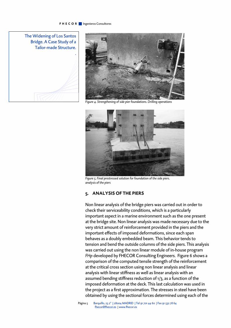
The first idea of merely increasing the foundation depth had to be partially abandoned following the initial underwater inspection of the side foundations which showed that concrete had suffered heavy deterioration due to poor construction using an innovative system at the time which has later proven to be deficient. This inspection lead to a new design for the side pier foundations while the central foundations were strengthened as stated above. For the side piers, an additional 3.00 meter slab was designed to carry the full load, with the existing foundations playing the role of a good soil. In order to connect this new foundation with the existing pier columns, prestressing was used. For this, 5 circular holes were drilled at the base of the columns in order to allow the passage of the prestressing ducts. Figure 4 shows the drilling operations and Figure 5 the final aspect of the new footing.
The Widening of Los Santos Bridge. A Case Study of a
Tailor-made Structure. .
F H E C O R Ingenieros Consultores
Página 5 Barquillo, 23 2º | 28004 MADRID | Tel 91 701 44 60 | Fax 91 532 78 64 [email protected] | www.fhecor.es
Figure 4. Strengthening of side pier foundations. Drilling operations
Figure 5. Final prestressed solution for foundation of the side piers. analysis of the piers
5. ANALYSIS OF THE PIERS
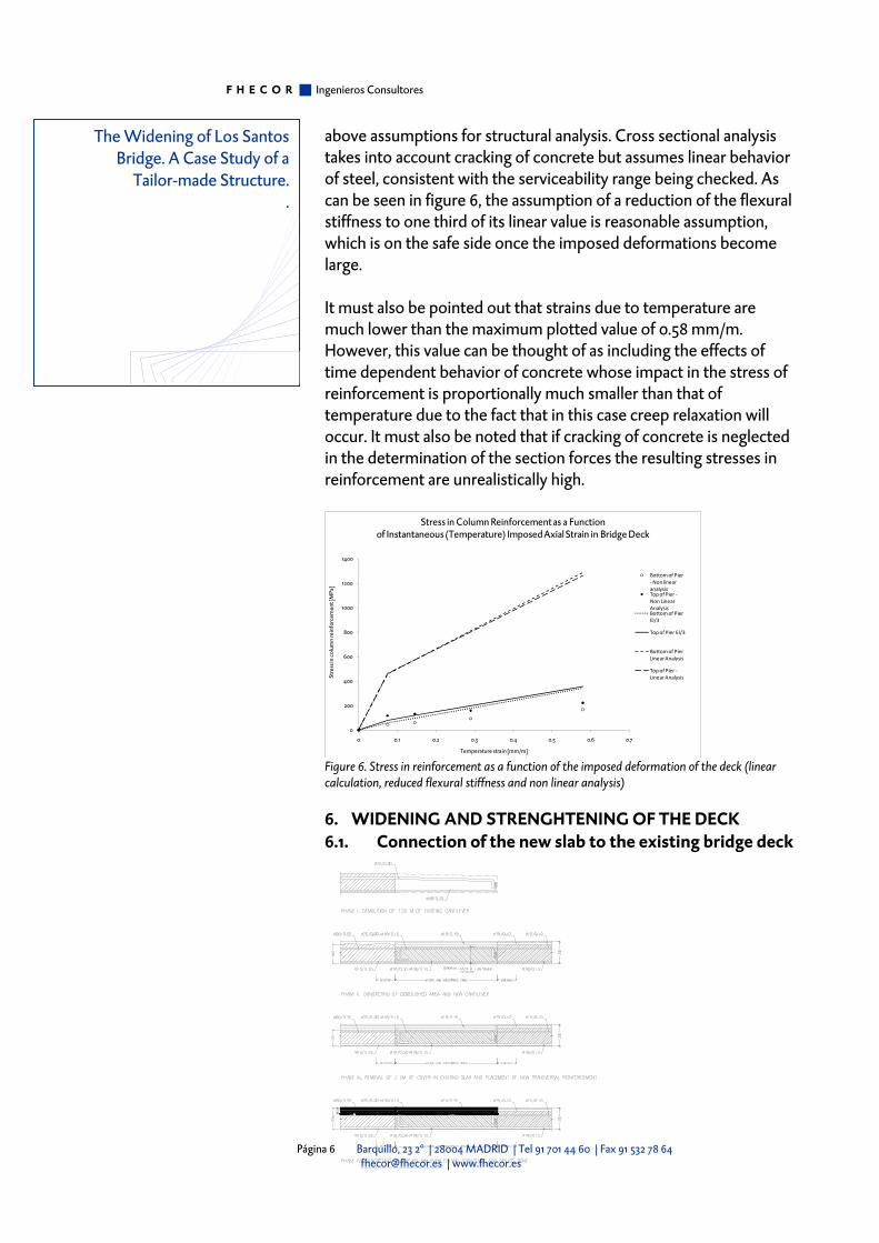
Non linear analysis of the bridge piers was carried out in order to check their serviceability conditions, which is a particularly important aspect in a marine environment such as the one present at the bridge site. Non linear analysis was made necessary due to the very strict amount of reinforcement provided in the piers and the important effects of imposed deformations, since each span behaves as a doubly embedded beam. This behavior tends to tension and bend the outside columns of the side piers. This analysis was carried out using the non linear module of in-house program FHp developed by FHECOR Consulting Engineers. Figure 6 shows a comparison of the computed tensile strength of the reinforcement at the critical cross section using non linear analysis and linear analysis with linear stiffness as well as linear analysis with an assumed bending stiffness reduction of 1/3, as a function of the imposed deformation at the deck. This last calculation was used in the project as a first approximation. The stresses in steel have been obtained by using the sectional forces determined using each of the
The Widening of Los Santos Bridge. A Case Study of a
Tailor-made Structure. .
F H E C O R Ingenieros Consultores
Página 6 Barquillo, 23 2º | 28004 MADRID | Tel 91 701 44 60 | Fax 91 532 78 64 [email protected] | www.fhecor.es
above assumptions for structural analysis. Cross sectional analysis takes into account cracking of concrete but assumes linear behavior of steel, consistent with the serviceability range being checked. As can be seen in figure 6, the assumption of a reduction of the flexural stiffness to one third of its linear value is reasonable assumption, which is on the safe side once the imposed deformations become large. It must also be pointed out that strains due to temperature are much lower than the maximum plotted value of 0.58 mm/m. However, this value can be thought of as including the effects of time dependent behavior of concrete whose impact in the stress of reinforcement is proportionally much smaller than that of temperature due to the fact that in this case creep relaxation will occur. It must also be noted that if cracking of concrete is neglected in the determination of the section forces the resulting stresses in reinforcement are unrealistically high.
0
200
400
600
800
1000
1200
1400
0 0.1 0.2 0.3 0.4 0.5 0.6 0.7
Stre
ss in
col
umn
rein
forc
emen
t [M
Pa]
Temperature strain [mm/m]
Stress in Column Reinforcement as a Function of Instantaneous (Temperature) Imposed Axial Strain in Bridge Deck
Bottom of Pier ‐Non linear analysis Top of Pier ‐Non Linear AnalysisBottom of Pier EI/3
Top of Pier EI/3
Bottom of Pier Linear Analysis
Top of Pier ‐Linear Analysis
Figure 6. Stress in reinforcement as a function of the imposed deformation of the deck (linear calculation, reduced flexural stiffness and non linear analysis)
6. WIDENING AND STRENGHTENING OF THE DECK 6.1. Connection of the new slab to the existing bridge deck
The Widening of Los Santos Bridge. A Case Study of a
Tailor-made Structure. .

F H E C O R Ingenieros Consultores
Página 7 Barquillo, 23 2º | 28004 MADRID | Tel 91 701 44 60 | Fax 91 532 78 64 [email protected] | www.fhecor.es
Figure 6. Construction phases of the connection between the existing slab and the new slab extension.
The existing concrete deck needed strengthening in order to carry the increased loads. The strengthening was achieved by three different measures: the concreting of an extra web inside the box girder, the connection to this web of a composite steel-concrete box section connected to the new web and placed at the lower face of the deck and the placement of external prestressing inside the box girder.
Figure 7 —Two phases of the construction process allowing the completion of the new slab and its connection to the existing deck. Traffic is maintained throughout the process.
The concrete deck has been widened by means of a reinforced concrete slab which is cast in place and connected to the existing slab. An additional support for this cantilever is provided by an inclined steel strut whose load is transferred by a transverse beam to the new web which is cast inside the deck. In order to connect the new slab with the old, the following procedure has been proposed. Traffic is first limited to one lane per direction leaving open to working operations first the central part of the deck and then the end of the cantilevers. This allows space for the execution of the vertical drills in the top and bottom slabs which allow the placement of the reinforcement needed for the new web, as well as the anchorages for the transverse steel beams (see top of Figure 7) and, afterwards, space to demolish 1.20 m of the slab located at the end of the cantilevers and. The new slab is concreted with a total depth near the connection of 0.25 m, except in the splice zone in which it is only 0.19 m deep, as shown in phase II of figure 6. Traffic is then shifted over to the new cantilever area (see bottom of figure 7). This is a critical situation since the inclined force component due to the struts, which reaches maximum values due to the location of the provisional traffic lanes) has to be resisted by the existing reinforcement of the existing top slab. This is possible only if the horizontal component of the strut force can be distributed over a large deck area. For these purposes the strut and
The Widening of Los Santos Bridge. A Case Study of a
Tailor-made Structure. .

F H E C O R Ingenieros Consultores
Página 8 Barquillo, 23 2º | 28004 MADRID | Tel 91 701 44 60 | Fax 91 532 78 64 [email protected] | www.fhecor.es
tie model of figure 8 was adopted. The idea is that the horizontal force is transmitted towards the end of the new cantilever and then balanced by the reinforcement located in a wide deck band. For this model to work properly longitudinal reinforcement in the new slab is necessary for the diffusion of the strut force. Figure 8. Strut and tie model showing how the horizontal component of the steel struts supporting the new slab can be resisted by the reinforcement of the existing structure if distribution of forces over a wide deck length is made possible. Longitudinal reinforcement is necessary in the new cantilever slab in order to provide equilibrium of forces.
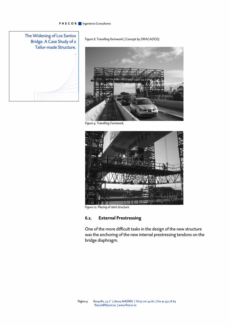
The shifting of traffic to the new cantilever is necessary in order to complete the connection between the old and new concrete. At this stage it is possible to demolish 3 cm from the top of the existing slab, place a new reinforcement and concrete over this reinforcement a depth of 6 cm corresponding to the sum of the 3 cm which were demolished plus a 3 cm increase in the depth of the slab. The placing of the steel structure and the concreting of the new slab require travelling formwork as shown in Figure 8 and 9. Figure 10 shows the placing of one of the transverse beams which support the inclined cantilever struts.
Fstrut=2996 kN
The Widening of Los Santos Bridge. A Case Study of a
Tailor-made Structure. .
F H E C O R Ingenieros Consultores
Página 9 Barquillo, 23 2º | 28004 MADRID | Tel 91 701 44 60 | Fax 91 532 78 64 [email protected] | www.fhecor.es
Figure 8. Travelling formwork ( Concept by DRAGADOS)
Figure 9. Travelling Formwork.
Figure 10. Placing of steel structure
6.2. External Prestressing
One of the more difficult tasks in the design of the new structure was the anchoring of the new internal prestressing tendons on the bridge diaphragm.
The Widening of Los Santos Bridge. A Case Study of a
Tailor-made Structure. .

F H E C O R Ingenieros Consultores
Página 10 Barquillo, 23 2º | 28004 MADRID | Tel 91 701 44 60 | Fax 91 532 78 64 [email protected] | www.fhecor.es
Figure 11. View of external prestressing inside the box girder crossing a diaphragm concreted in order to limit distortion of the deck.
It is the case that in order to anchor the internal prestressing tendons on the triangular pier diaphragms, the reinforcement provided in the original structures was heavily damaged by the drilling necessary to anchor the prestressing cables. This reinforcement is necessary in order to carry the unbalanced live loads to the pier columns. In order to compensate for this loss a heavy vertical prestressing was introduced in the central web as shown in figure 12.
Figure 12. Vertical prestressing at pier cross section in order to compensate for the loss of reinforcement in the inclined diaphragm walls due to the drilling necessary to anchor external prestressing cables.
The Widening of Los Santos Bridge. A Case Study of a
Tailor-made Structure. .

F H E C O R Ingenieros Consultores
Página 11 Barquillo, 23 2º | 28004 MADRID | Tel 91 701 44 60 | Fax 91 532 78 64 [email protected] | www.fhecor.es
7. CONCLUSIONS
The project for the widening of Los Santos Bridge, briefly described in this paper, has been a highly challenging engineering task. By making use of the available resistance mechanisms of the existing structure it has been possible to dramatically lower costs. The process at arriving at the final solution has been the result of fruitful discussion between engineers connected with design and construction and has involved a great amount of energy devoted to ideas and the filtering of a large number of proposals. It has also proven to be a rocky road with constructions problems ranging from the unexpectedly poor condition of the existing foundations to anchorage failures in prestressing cables and more problems yet to come. But, in the end, such a project captures, in a way, the essence of engineering practice in making possible a goal very much constrained, in this case by an existing structure, giving way to a final result that has a certain amount of beauty as well as usefulness. 8. REFERENCES
García-Arango Cienfuegos-Jovellanos, I. “Puente de Los Santos: Cruzar la Ría”
The Widening of Los Santos Bridge. A Case Study of a
Tailor-made Structure. .