the incremental commitment spiral model …csse.usc.edu/techrpts/phd_dissertations/files/... ·...
TRANSCRIPT

THE INCREMENTAL COMMITMENT SPIRAL MODEL PROCESS PATTERNS
FOR RAPID‐FIELDING PROJECTS
by
Supannika Koolmanojwong
A Dissertation Presented to the FACULTY OF THE USC GRADUATE SCHOOL UNIVERSITY OF SOUTHERN CALIFORNIA
In Partial Fulfillment of the Requirements for the Degree DOCTOR OF PHILOSOPHY (COMPUTER SCIENCE)
December 2010
Copyright 2010 Supannika Koolmanojwong

ii
Acknowledgements
During my PhD journey, I have encountered numerous successes and many failures.
I am so fortunate to receive countless encouragements, opportunities, friendships, and
trusts from many people that I am indebted to.
First and foremost, I am grateful and thankful to my advisor, Prof. Barry Boehm, for
his tremendous supports and for believing in my PhD study feasibility evidence. I would like
to thank my dissertation committee members: Prof. Stan Settles, Prof. Nenad Medvidovic,
Dr. Robert Neches and Dr. Rick Selby for their valuable feedback and numerous constructive
critiques.
My journey would not have been fun without a good company. I would like to thank
for the warmest supports from Computer Science department and CSSE family: Pongtip
Aroonvatanaporn, Jo Ann Lane, Vu Nguyen, Qi Li, Aaron Chang, Thomas Tan, Julie Sanchez
and Monvorath Phongpaibul.
I would like to express my gratitude to Dr. Fred Hadaegh for help shaping up my
journey.
My dissertation would not have been possible without USC Software Engineering
course students, clients, teaching assistants, and graders. Thank you for the data and
participation in the study.
I also find myself lucky to have colleagues and friends from Assumption University,
Thailand, who tagged along and comforted me in various trips of my life.
The endless thanks go to my husband Sohrab Mobasser, and his family for
continuously giving me a hug, a hand, hope, happiness, humor, and huge amount of love that

iii
I never thought I could get from anyone. I also have to thank Tooleh for her unconditional
love. She is the best buddy and the best audience I have ever had.
My journey could not be started and could not be completed without my devoted
mom and my brothers. Your love and your caring give me strengths to overcome all
obstacles.
Lastly, I am indebted to my father who inspired me to start my journey. I know you
are proud of me. I am honored to be your daughter and I miss you very single day.

iv
Table of Contents
Acknowledgements ii
List of Figures vi
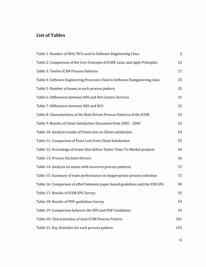
List of Tables ix
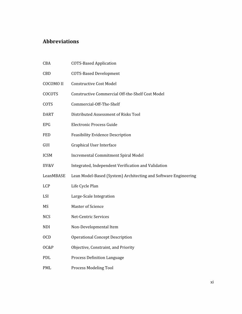
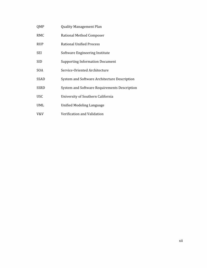
Abbreviations xi
Abstract xiii
Chapter 1 : Introduction 1 1.1. Motivation 1 1.2. Research Questions 3 1.3. Research Contribution 4 1.4. Organization of Dissertation 4
Chapter 2 : Background and Related Work 6 2.1. The Incremental Commitment Spiral Model (ICSM) 6 2.2. Definitions of Non‐Developmental Items and Net‐Centric Services 10 2.3. Related Software Development Processes for Rapid‐Fielding Projects 11 2.3.1. ICSM, Lean Principles, and Agile Principles 11 2.3.2. CBA Process Decision Framework 13 2.3.3. COTS Interoperability Framework 15 2.4. Process Patterns of Software Development Project 16 2.5. USC Software Engineering Course 19 2.6. Electronic Process Guide Generator Tools 19 2.6.1. Spearmint 20 2.6.2. Little‐JIL 20 2.6.3. IBM Rational Method Composer 21
Chapter 3 : Research Methodology 23 3.1. Research Timeline 23 3.2. Hypotheses 26 3.3. Threats to Validity 27
Chapter 4 : Process Patterns in Rapid‐Fielding Projects 29 4.1. Different Opportunities or Risk Patterns in Rapid‐Fielding Project 29 4.2. Differences between NDI and Services 30 4.3. Rapid‐Fielding Project Characteristics 32 4.4. NDI/NCS Process Decision Framework 33 4.5. Work Breakdown Structure in Rapid‐Fielding Process 47 4.6. Validation Results 52

v
4.6.1. Client Satisfaction 52 4.6.2. Faster Time to Market Projects in Software Engineering Class 54 4.6.3. Conclusion 55
Chapter 5 : Decision Criteria of Process Deployment 56 5.1. Process Decision Driver 56 5.2. Discussion with Field Experts 64 5.3. Process Adoption 65 5.3.1. Incidents of Process Selection and Direction Changes 66 5.3.2. Incidents of Wrong Process Selection 69 5.3.3. Conclusion 73
Chapter 6 : The ICSM Electronic Process Guide 75 6.1. Representation of Process Elements and Their Relationship 76 6.2. Process Representation 80 6.3. Discussion 83 6.3.1. Comparison Software Process Modeling Tools 83 6.3.2. ICSM EPG Analysis 87 6.3.3. Effort Comparison between EPG and non‐EPG 89 6.3.4. Qualitative Feedback from students’ survey results 90 6.3.5. Quantitative Survey Results on ICSM EPG 91 6.3.6. Quantitative Survey Results regarding PDF‐guideline vs EPG 92 6.3.7. Conclusions 93
Chapter 7 : Conclusion and Future Work 95 7.1. General Conclusions 95 7.2. Summary of Contributions 95 7.3. Future Work 96
References 97
Appendices Appendix A : Characteristics of each ICSM Process Pattern 101 Appendix B : Key Activities for Each Process Pattern of the ICSM 103 Appendix C : CSCI 577 projects 104 Appendix D : Projects that deliver in one‐semester 108 Appendix E : Student General Information Questionnaire 109 Appendix F : Effort Category 113 Appendix G : ICSM EPG: Roles, Activities, Work products, and Delivery Process 114 Appendix H : Example of Decision driver 119 Appendix I : Client Feedback Form – CSCI 577a 125 Appendix J : Client Feedback Form – CSCI577b 127 Appendix K : Qualitative Interview Form 129 Appendix L : Results of ICSM EPG Survey 131 Appendix M : Software Process Guidelines Survey 132 Appendix N : Results of Software Process Guidelines Survey 138

vi
List of Figures
Figure 1: Net Centric Services Usage in USC Software Engineering Class 2
Figure 2: Statistics about Mashup created and listed at ProgrammableWeb.com 3
Figure 3: Overview of the Incremental Commitment Spiral Model 8
Figure 4: Phased View of the Generic Incremental Commitment Spiral Model Process 9
Figure 5: CBA Process Decision Framework 15
Figure 6: COTS Interoperability Framework 16
Figure 7: An example page of a Spearmint‐based process guide 20
Figure 8: Tree‐like structure diagram of Little‐JIL 21
Figure 9: An example of an IBM RMC page 22
Figure 10: Dissertation Development Approach 24
Figure 11: Dissertation Timeline 24
Figure 12: Different Opportunities and Risk Patterns yield Different Processes 30
Figure 13: NDI Process Decision Framework 34
Figure 14: Identify OC&Ps and explore alternatives 35
Figure 15: Assess NDI/Services Candidates 40
Figure 16: Check Interoperability 43
Figure 17: Tailor a single NDI/ Service 43
Figure 18: Tailor multiple NDI/Services 44
Figure 19: Develop Glue Code 46
Figure 20: Delivery Process in Exploration Phase 47
Figure 21: Delivery Process in Valuation phase 49

vii
Figure 22: Delivery Process in Foundations phase 50
Figure 23: Development phase ‐ Construction increment 50
Figure 24: Delivery Process in Development phase ‐ Trnaition increment 51
Figure 25: Translating Rating Scales to Process Template 62
Figure 26: An Example of Using Decision Drivers to map with an NDI‐Intensive Project 63
Figure 27: Example of Process Pattern Selection 64
Figure 28: Result of right process pattern selection 66
Figure 29: Results of incorrect process selection due to unclear project scope 67
Figure 30: Result of incorrect process selection due to minor changes 68
Figure 31: Results of Process Re‐Selection due to available NCS 68
Figure 32: Result of infeasible project 69
Figure 33: The Incremental Commitment Spiral Model Electronic Process Guide 75
Figure 34: View of Operational Concept Development Practice 78
Figure 35 Defining Relationship between Process Elements 79
Figure 36: Relationship between roles, tasks, and work product 79
Figure 37: Overview of the ICSM EPG 80
Figure 38: Work Breakdown Structure for Architected Agile Process 82
Figure 39: Activity Diagram of an Explore Current System Activity 82
Figure 40: Student Background Information Survey ‐ Page 1 109
Figure 41: Student Background Information Survey ‐ Page 2 110
Figure 42: Student Background Information Survey ‐ Page 3 111
Figure 43: Student Background Information Survey ‐ Page 4 112
Figure 44: Welcome Page of ICSM EPG 114
Figure 45: List of Roles in ICSM EPG 115

viii
Figure 46: List of Practices in ICSM EPG 115
Figure 47: Practice Page in ICSM EPG 116
Figure 48: A task page in ICSM EPG 117
Figure 49: A role and responsibilities page in ICSM EPG 117
Figure 50: A delivery process page in ICSM EPG 118
Figure 51: list of work products in ICSM EPG 118
Figure 52: Architected Agile Process Pattern Template 119
Figure 53: Use Single NDI Process Pattern Template 120
Figure 54: NDI‐Intensive Process Pattern Template 120
Figure 55: Services‐Intensive Process Pattern Template 121
Figure 56: An Architected Agile team with Architected Agile Decision Pattern 121
Figure 57: An Architected Agile team with Use Single NDI Decision Pattern 122
Figure 58: An Architected Agile team with NDI‐Intensive Decision Pattern 122
Figure 59: An Architected Agile team with Services‐Intensive Decision Pattern 122
Figure 60: An NDI‐intensive team with NDI‐Intensive Decision Pattern 123
Figure 61: An NDI‐intensive team with Architected Agile Decision Pattern 123
Figure 62: An NDI‐intensive team with Use Single NDI Decision Pattern 124
Figure 63: An NDI‐intensive team with Services‐Intensive Decision Pattern 124
ix
List of Tables
Table 1: Number of NDI/ NCS used in Software Engineering Class 2
Table 2: Comparison of the Core Concepts of ICSM, Lean, and Agile Principles 12
Table 3: Twelve ICSM Process Patterns 17
Table 4: Software Engineering Processes Used in Software Enmgineering class 25
Table 5: Number of teams in each process pattern 25
Table 6: Differences between NDI and Net‐Centric Services 31
Table 7: Differences between NDI and NCS 32
Table 8: Characteristics of the Risk‐Driven Process Patterns of the ICSM 33
Table 9: Results of Client Satisfaction Document from 2005 ‐ 2009 52
Table 10: Analysis results of Points lost on Client satisfaction 53
Table 11: Comparison of Point Lost from Client Satisfaction 53
Table 12: Percentage of teams that deliver Faster Time‐To‐Market projects 54
Table 13: Process Decision Drivers 56
Table 14: Analysis on teams with incorrect process patterns 72
Table 15: Summary of team performance on inappropriate process selection 73
Table 16: Comparison of effort between paper‐based guidelines and the ICM EPG 90
Table 17: Results of ICSM EPG Survey 92
Table 18: Results of PDF‐guidelines Survey 93
Table 19: Comparison between the EPG and PDF‐Guidelines 93
Table 20: Characteristics of each ICSM Process Pattern 101
Table 21: Key Activities for each process pattern 103

x
Table 22: List of Projects and their processes in Fall 2005 104
Table 23: List of Projects and their processes in Fall 2006 105
Table 24: List of Projects and their processes in Fall 2007 106
Table 25: List of Projects and their processes in Fall 2008 107
Table 26: List of Projects and their processes in Fall 2009 107
Table 27: List of one‐semester projects 108
Table 28: Effort Categories in Effort Reporting System 113
Table 29: Results of ICSM EPG Survey 131
Table 30: Results of Software Process Guidelines Survey 138
xi
Abbreviations
CBA COTS‐Based Application
CBD COTS‐Based Development
COCOMO II Constructive Cost Model
COCOTS Constructive Commercial Off‐the‐Shelf Cost Model
COTS Commercial‐Off‐The‐Shelf
DART Distributed Assessment of Risks Tool
EPG Electronic Process Guide
FED Feasibility Evidence Description
GUI Graphical User Interface
ICSM Incremental Commitment Spiral Model
IIV&V Integrated, Independent Verification and Validation
LeanMBASE Lean Model‐Based (System) Architecting and Software Engineering
LCP Life Cycle Plan
LSI Large‐Scale Integration
MS Master of Science
NCS Net‐Centric Services
NDI Non‐Developmental Item
OCD Operational Concept Description
OC&P Objective, Constraint, and Priority
PDL Process Definition Language
PML Process Modeling Tool
xii
QMP Quality Management Plan
RMC Rational Method Composer
RUP Rational Unified Process
SEI Software Engineering Institute
SID Supporting Information Document
SOA Service‐Oriented Architecture
SSAD System and Software Architecture Description
SSRD System and Software Requirements Description
USC University of Southern California
UML Unified Modeling Language
V&V Verification and Validation

xiii
Abstract
To provide better services to customers and not to be left behind in a competitive business
environment, a wide variety of ready‐to‐use software and technologies are available for
one to grab and go and build up software systems at a very fast pace. Rapid fielding plays a
major role in developing software systems to provide a quick response to the organization.
This research investigates the appropriateness of current software development processes
and develops new software development process guidelines, focusing on four process
patterns: Use single NDI, NDIintensive, Servicesintensive, and Architected Agile.
Currently, there is no single software development process model that is applicable to all
four process patterns, but the Incremental Commitment Spiral Model (ICSM) can help a new
project converge on a process that fits the project process scenario. The output of this
research has been implemented as an Electronic Process Guide for USC Software
Engineering students to use as a guideline to develop real‐client Software Engineering
course projects. An empirical study has been conducted to assess the suitability of the
newly developed process as compared to results data from previous course projects.
Subject to sources of variability in the nature of the projects, the assessment confirmed that
the process selection guidelines led project teams to choose the most appropriate process
pattern, and that the performance of the project teams choosing inappropriate processes
produced less satisfactory results.
1
Chapter 1 : Introduction
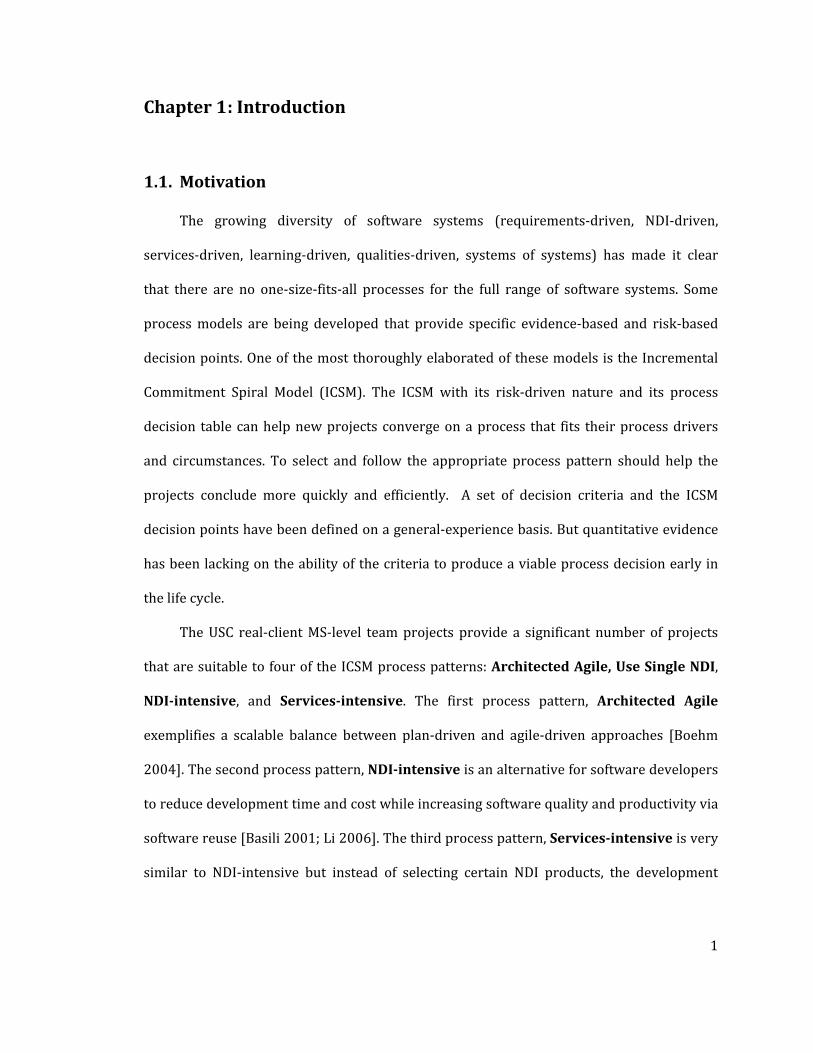
1.1. Motivation
The growing diversity of software systems (requirements‐driven, NDI‐driven,
services‐driven, learning‐driven, qualities‐driven, systems of systems) has made it clear
that there are no one‐size‐fits‐all processes for the full range of software systems. Some
process models are being developed that provide specific evidence‐based and risk‐based
decision points. One of the most thoroughly elaborated of these models is the Incremental
Commitment Spiral Model (ICSM). The ICSM with its risk‐driven nature and its process
decision table can help new projects converge on a process that fits their process drivers
and circumstances. To select and follow the appropriate process pattern should help the
projects conclude more quickly and efficiently. A set of decision criteria and the ICSM
decision points have been defined on a general‐experience basis. But quantitative evidence
has been lacking on the ability of the criteria to produce a viable process decision early in
the life cycle.
The USC real‐client MS‐level team projects provide a significant number of projects
that are suitable to four of the ICSM process patterns: Architected Agile, Use Single NDI,
NDIintensive, and Servicesintensive. The first process pattern, Architected Agile
exemplifies a scalable balance between plan‐driven and agile‐driven approaches [Boehm
2004]. The second process pattern, NDIintensive is an alternative for software developers
to reduce development time and cost while increasing software quality and productivity via
software reuse [Basili 2001; Li 2006]. The third process pattern, Servicesintensive is very
similar to NDI‐intensive but instead of selecting certain NDI products, the development

2
team considers to deploy available web services. Lastly, Use single NDI provides an option
of a ready‐to‐use product either as a complete project solution or as a partial development
solution.
Table 1: Number of NDI/ NCS used in Software Engineering Class
# of teams # of NDI # of NCS
Fall 2005 18 28 1Fall 2006 20 23 6Fall 2007 20 17 9Fall 2008 16 10 9Fall 2009 14 7 18
Figure 1: Net Centric Services Usage in USC Software Engineering Class
For Services‐intensive projects, based on projects from at USC’s Software
Engineering Class, Figure 1 and Table 1 show an increasing trend in using net centric
services in real‐client software development projects. This increase is not only seen in the
academic environment, but also 80% of the world economy provides services in various
forms [CMMI‐Services]. In addition, as shown in Figure 2, in each day, there are about 3 new
mashups or web service extensions created and listed at programmableweb.com
[Programmableweb.com 2009]. The users who are consuming these services need to know

3
how to select the appropriate service and utilize the service properly. Moreover, based on
our preliminary study from fall’08‐spring’09 projects, we found that for some projects, a
pure COTS‐Based Development process does not fit well for Net‐Centric Services case.
Figure 2: Statistics about Mashup created and listed at ProgrammableWeb.com
This research mainly experimented with new software development processes for
Architected Agile and Services‐Intensive and extended Yang and Boehm’s COTS‐Based
Application Development guidelines (CBD) [Yang 2006] by using the risk‐driven approach
of the Incremental Commitment Spiral Model and incorporated feedback from Bhuta’s
empirical analysis on COTS interoperability assessment [Bhuta 2007].
1.2. Research Questions
Research questions are developed around the concepts of process modeling and process
improvement.
RQ1. How does the Incremental Commitment Spiral Model fit in each process pattern?
RQ2. What are the decision criteria that branch a project to each process pattern?
RQ3. What activities, roles, responsibilities, and work products should exist for each process
pattern?

4
RQ4. In what ways do the process patterns improve project outcomes?
RQ5. In what ways could the process patterns be improved?
1.3. Research Contribution
The research is intended to provide the following contributions:
• Current Software Development Process Investigation and Analysis – Based on
the 4 types of rapid‐fielding projects, the related software development process
guidelines or standards are investigated and analyzed for their usability,
completeness and appropriateness.
• Software Development Process Guidelines for 4 process patterns are authored
by integrating, tailoring and extending from CBA Process Decision Framework [Yang
2006], COTS Integration Framework [Bhuta 2007] and the Incremental
Commitment Spiral Model [Boehm 2009a].
• Decision Criteria of Process Deployment is developed in order to support the
development team to select the appropriate process pattern.
• The ICSM Electronic Process Guide is developed by using IBM Rational Method
Composer and is currently use as the main development guidelines for the
development team in software engineering class.
1.4. Organization of Dissertation
The organization of this dissertation is as follows:
5
Chapter 2 presents the survey results of current software development process,
background information about the Incremental Commitment Spiral Model and other related
works
Chapter 3 explains about research methodology and experiments used to test the
hypotheses
Chapter 4 describes about rapid‐fielding process patterns, the differences between Non‐
Developmental Item and Net‐Centric Services and discusses the evaluation results on
datasets from Software Engineering class from 2005 – 2009
Chapter 5 provides detailed information about process decision drivers and discusses
the evidence of process selection and re‐selection.
Chapter 6 explains about the Incremental Commitment Spiral Model – Electronic
Process Guide (ICSM‐EPG) and analyzes the experimental results.
Chapter 7 summarizes the contributions and proposes future research work.

6
Chapter 2 : Background and Related Work
2.1. The Incremental Commitment Spiral Model (ICSM)
The ICSM [Boehm and Lane 2007; Pew and Mavor 2007] is a new generation process
model. ICSM covers the full system development life cycle consisting of the Exploration
phase, Valuation phase, Foundations phase, Development phase, and Operation phase.
ICSM, as shown in Figure 3, has been evaluated to be a reasonably robust framework for
system development. The four underlying principles of the ICSM include
1) Stakeholder valuebased system definition and evolution – The project
should be developed based on win‐win conditions for all success‐critical
stakeholders, otherwise the stakeholders will frequently not commit to the project
and will gradually lead to project rejection or ignorance.
2) Incremental commitment and accountability – the success of the project must
be built upon the participation, commitment, and accountability of the success
critical stakeholders, otherwise the final product will not be the system that are
most needed.
3) Concurrent system and software definition and development – contrary to
sequential development, the concurrent development of requirements, solutions,
hardware, software, and human factors allows the project to move faster and be
more flexible to yield the best results.
7
4) Evidence and riskbased decision making – evidence of project feasibility is
the key ingredient to avoid the risks and can be used to determine the future of the
project.
One of the main focuses of the ICSM is feasibility analysis; evidence must be
provided by the developer and validated by independent experts. The ICSM combines the
strengths of various current process models and limits their weaknesses. The ICSM, like the
V‐Model [V‐Model 2009], emphasizes early verification and validation, but allows for
multiple‐incremental interpretation and alleviates sequential development. Compared to
the Spiral Model [Boehm 1988], the ICSM also focuses on risk‐driven activity prioritization,
but offers an improvement by adding well‐defined in‐process milestones. While ICSM, RUP,
and MBASE [Boehm 1996] perform concurrent engineering that stabilizes the process at
anchor point milestones, ICSM also supports integrated hardware‐software‐human factors
oriented development. Compared with Agile methods [Agile 2009], ICSM embraces
adaptability to unexpected change perspective, and at the same time it allows scalability.

8
1
2
3
4
5
6
RISK-BASEDSTAKEHOLDER COMMITMENT REVIEW POINTS:
Opportunities to proceed, skip phases backtrack, or terminate
Exploration Commitment Review
Valuation Commitment Review
Foundations Commitment Review
Development Commitment Review
Operations1 and Development2Commitment Review
Operations2 and Development3Commitment Review
Cumulative Level of Understanding, Product and Process Detail (Risk-Driven)
Concurrent Engineering of Products and Processes
2345
EXPLORATION
VALUATION
FOUNDATIONS
DEVELOPMENT1FOUNDATIONS2
OPERATION2DEVELOPMENT3
FOUNDATIONS4
16
Evidence-Based Review Content- A first-class deliverable- Independent expert review- Shortfalls are uncertainties and risks
OPERATION1DEVELOPMENT2
FOUNDATIONS3
Risk
Risk-Based Decisions
AcceptableNegligible
High, butAddressable
Too High, Unaddressable
Figure 3: Overview of the Incremental Commitment Spiral Model
When the spiral in Figure 3 is unrolled, the ICSM can be represented in another
perspective which focuses on activities in each phase (Figure 4). In the Exploration phase, a
development team focuses on initial scoping, studying current system, and exploring
alternatives. Some of the activities in the Valuation phase include developing operational
concept, prioritizing requirements, assessing the non‐developmental products, and
studying business case analysis. In the Foundations phase, the development team focuses
on building the system and software architecture, acquiring the non‐developmental items,
and creating a development iteration plan. One or more development increments occur in
the development phase. Additionally, transition plan is also defined in the Development
phase. Finally, the project is delivered and deployed in the Operation phase.

9
Another core concept of the ICSM is risk‐based decisions which can be easily seen in
both Figure 3 and Figure 4. Direction of a project can be determined by opportunities and
risks. For each milestone, a project must assess their project status in order to find an
opportunity to skip a phase when a risk is negligible or to move on to the next phase when a
risk is acceptable. At the same time, a project must assess their risks in order to determine
whether the project should repeat the same phase when a risk is high but addressable or
halt a project in order to adjust the scope, priorities or discontinue a project when the risk is
too high and not addressable.
Figure 4: Phased View of the Generic Incremental Commitment Spiral Model Process

10
2.2. Definitions of NonDevelopmental Items and NetCentric Services
NonDevelopmental Items (NDI) Among various interpretations of non‐
developmental items (NDI), the most common definition [Smith 2004] [FAR] of NDI is a
previously developed component that includes Commercial‐Off‐The‐Shelf, Government‐Off‐
The‐Shelf, Research‐Off‐The‐Shelf, Open Source Software Technology and Products, Reuse
Code, Reuse library, and Customer‐furnished package. NDI can be categorized into two
types; System NDI and Application NDI. A system NDI is an NDI that serves as an
infrastructure to the development project such as MySQL, Apache, and Eclipse. An
application NDI is an NDI that provides functionalities as a part of the project deliverables.
Examples of an application NDI are WordPress, Crystal Reports, and Joomla.
NetCentric Services (NCS) Net‐Centric Services (NCS) is a program or a service
available over the internet. NCS is also known as web service, web application, online
application, cloud computing, and software‐as‐a‐service. Examples of NCS are Salesforce,
Google map, Paypal, and Moodle.
NDIintensive system – it is previously known as COTS‐based application. An NDI‐
intensive system is a system for which at least 30% of the end‐user functionality is provided
by NDI products, and at least 10 % of the development effort is devoted to NDI
considerations [Yang 2006]. Similar to NDI‐intensive system, NCS or Services‐intensive
system is a system that at least 30% of the end‐user functionality is provided by NCS
products, and at least 10 % of the development effort is devoted to NCS considerations.

11
2.3. Related Software Development Processes for RapidFielding
Projects
The process patterns of software development processes in ICSM are developed by
combining strengths from several development processes. This section summarizes the
related process guidelines for the four rapid‐fielding process patterns.
The Architected Agile case balances a plan‐driven development process in building up
the steady architecture and an agile‐driven development process in iterative incremental
and frequent delivery as practice in Scrum [Rising 2000] or Agile Unified Process [Ambler
2009]. On the other hand, the Software Engineering Institute (SEI) CMMI‐COTS [CMMI‐
COTS 2009] and USC‐CSSE COTS‐Based Development (CBD) Guidelines [Yang 2007] provide
strong foundations for NDI‐Intensive or COTS‐Based systems (CBS). Regarding Services‐
Intensive, most of the processes, including CMMI‐SVC [CMMI‐SVC 2009], cover only the
process of how to develop and maintain web services. None of them is able to pick, choose
and use available online services. Early user‐programming guidance [Scaffidi 2009]
provides basic guidelines for Use Single NDI process, but focuses only on tailoring the
selected NDI. Hence, none of the current process guidelines provide perfect fit to the rapid‐
fielding process.
Sections 2.3.1‐2.3.3 provide brief information of the process models or framework
that are selected as foundations for the rapid‐fielding process patterns.
2.3.1. ICSM, Lean Principles, and Agile Principles
Lean software development is adapted from the principle developed by Toyota
product system [Poppendieck 2003]. Lean Thinking focuses on built‐in quality, continuous
improvement, waste elimination, committed leadership and do the right job and doing the

12
job right [Oppenheim 2010]. Well‐known Lean techniques and concepts include Kanban,
Just‐in‐Time, and Kaizen.
Agile Software development is a set of lightweight software development
approaches which is based on rapid development, high collaboration, and adaptation
throughout software development life cycle [Agile 2009]. Various well‐known agile
approaches and techniques include Scrum, Extreme Programming, Open Unified Process,
Pair Programming, and Code Refactoring.
The ICSM shares common characteristics with Lean and Agile Principles. All
principles focus on giving high priority to high‐value added activities and avoid low‐value
added activities. Table 2 compares the four core concepts of the Incremental Commitment
Spiral Model, Lean Principles [Poppendieck 2003], and Agile Principles. [Boehm 2007b;
Agile Manifesto 2007]
Table 2: Comparison of the Core Concepts of ICSM, Lean, and Agile Principles
ICSM Principles Related Lean Principles Related Agile Principles
1. Stakeholder value‐based system definition and evolution
• Respected leaders and champions
• Team commitment • Master developers to guide decisions, make rapid progress, and develop high‐quality software
• Joint customer‐developer iteration planning
• Value stream mapping
• Business people and developers must work together daily throughout the project
• Provide the developers with environment and support need
• Joint customer‐developer iteration planning
• Satisfy the customer through early and continuous delivery of valuable software
2. Incremental commitment and accountability
• Balance experimentation with deliberation and review
• Iteration planning with negotiable scope and convergence
• Deliver working software frequently
• Working software is the primary measure of progress

13
Table 2: Continued
3. Concurrent system and software definition and development
• Decide as late as possible to support concurrent development while keeping options open
• Ensure emergence of a good architecture through reuse, integrated problem solving, and experienced developers
• The best architectures, requirements, and designs emerge from self‐organizing teams.
4.Evidence and risk‐based decision making
• Eliminate waste • Value stream mapping
• Team reflects periodically on how to become more effective, then tunes and adjusts its behavior accordingly
• Simplicity‐‐the art of maximizing the amount of work not done‐‐is essential.
2.3.2. CBA Process Decision Framework
The COTS‐Based Application Process Decision Framework [Yang 2006] is a process
model generator. It enables the development teams to determine course of actions based on
the appropriate combinations of Assessing, Tailoring, Glue coding, and Custom coding
process elements that best fit their project situation and dynamics.
There are five principles for CBA development as follows:
• Process happens where the effort happens – comparing to non‐CBA teams, CBA
teams tend to spend more time in assessing the alternative products and spend little
time in tailoring, glue coding, and custom coding.
• Don’t start with requirements – committing to a hard requirements before completely
assessing the alternative products would lead to limited choice of COTS. Instead, the
team should start with flexible win conditions.

14
• Avoid premature commitments, but have and use a plan – tailor a process to
accommodate the process of COTS selection, integration, and maintenance.
• Buy information early to reduce risk and rework – use the opportunities of trial
version of various COTS to assess the product or develop prototypes to check the
project feasibility. On the other hand, the team needs to find a sweet spot by not
spending too much time in assessing and selecting COTS.
• Prepare for COTS change – with the average of a COTS upgrade in every 10 months,
the development should spend a good amount of effort in assessing market analysis and
product‐line of the potential COTS.
Ye Yang’s COTS‐Based Application (CBA) Process Decision Framework [Yang 2006],
as shown in Figure 5, provides notable foundations for general non‐developmental item
(NDI)‐intensive development. However, with the fast‐pacing technologies, there are some
drawbacks of the framework that need improvements to fit the technology and recent
transformation gaps, such as missing COTS interoperability analysis and missing multiple
COTS tailoring process. Moreover, her COTS‐Based Development Process guidelines [Yang
2007] including the artifact templates, are not fully applicable to Net‐Centric Services
(NCS)‐intensive development. The new version of NDI/NCS process decision framework is
discussed in section 4.4.

15
Figure 5: CBA Process Decision Framework
2.3.3. COTS Interoperability Framework
With various COTS available in the market, the development team opts to deploy
commercial products to support in complex functionalities. Using multiple COTS often
create the possibility of interoperability conflicts resulting in budget and schedule overruns.
As shown in Figure 6, Bhuta’s COTS interoperability framework [Bhuta 2007] encourages
the development team to analyze the interoperability between multiple COTS selection.
Hence, the risks, costs, and efforts regarding COTS mismatch are significantly reduced. On
the other hand, it is also important to remark that this framework might not provide great
benefits to multiple net‐centric services, due to their global standard and platform
independence.

16
Figure 6: COTS Interoperability Framework
2.4. Process Patterns of Software Development Project
Software development projects can be ranged from a very small and simple blogging
website to a very large, complex and life‐critical system such as Medical device product line
or Command, Control, Computing, Communications, Intelligence, Surveillance,
Reconnaissance (C4ISR) system. By using the system’s size and complexity, its rate of
change, its mission‐criticality, the extent of non‐developmental item (NDI) support for its
desired capabilities, and the available organizational and personnel capability for
developing the system, the software development projects can be categorized into 12
process patterns [Boehm 2009b] as shown in Table 3. More information can be found in
Appendix A and Appendix B.

17
Table 3: Twelve ICSM Process Patterns
Common Case
Size, Com
plexity
Change Rate
(%/M
onth)
Application
Criticality
Available NDI
Products
Organizational
and
Personnel
Capability
Use NDI Complete Agile Low 1‐30 Low‐Med Good; in place Agile‐ready Med‐high Architected Agile Med 1‐10 Med‐High Good; most in
place Agile‐ready Med‐high
Formal Methods Low 0.3 Extra High None Strong formal methods experience
HW with embedded SW component
Low 0.3‐1 Med‐Very High
Good; in place Experienced; med‐high
Indivisible IOC Med‐High
0.3‐1 High‐ Very High
Some in place Experienced; med‐high
NDI‐ intensive Med‐High
0.3‐3 Med‐Very High
NDI‐driven architecture
NDI‐ experienced; med‐high
Hybrid agile/ plan‐driven
Med‐Very High
Mixed parts; 1‐10
Mixed parts; Med‐Very High
Mixed parts Mixed parts
Multi‐owner system of systems
Very High
Mixed parts; 1‐10
Very High Many NDIs; some in place
Related experience, med‐high
Family of systems Med‐Very High
1‐3 Med‐Very High
Some in place Related experience, med‐high
Brownfield High‐Very High
0.3‐3 Med‐High NDI as legacy replacement
Legacy re‐engineering
Net‐ Centric Services— Community Support
Low‐Med
0.3‐3 Low‐Med Tailorable service elements
NDI‐ experienced
Net‐Centric Services—Quick Response Decision Support
Med‐High
3‐30 Med‐High Tailorable service elements
NDI‐ experienced
Legend : HW: Hardware; IOC: Initial Operational Capability; NDI: Non‐Development Item; SW: Software.

18
For the small e‐services projects developed in the software engineering project
course, four of the 12 process patterns of the ICSM predominate:
Architected Agile ‐ For a less than 80 agile‐ready‐people team and a fairly mature
technology project, agile methods can be scaled up using an Architected Agile approach,
emphasizing early investment in a change‐prescient architecture and all success‐critical‐
stakeholders team building [Boehm 2004]. The Valuation and Foundations phases can be
brief. A scrum of Scrums approach can be used in the Development phase.
Use Single NDI – When an appropriate NDI (COTS, open source, reuse library,
customer‐furnished package) solution is available, it is an option to either use the NDI or
develop, perhaps, a better version by oneself, or outsource such a development, which
generally incurs more expense and takes longer to begin capitalizing on its benefits. On the
other hand, an NDI may come with high volatility, complexity, or incompatibility. Major
effort will then be spent on appraising the NDI.
NDIIntensive – An NDI‐Intensive system is a system in which 30% of end‐user
functionality is provided by NDI [Yang 2006]. A great deal of attention goes into appraising
the functionality and interoperability of NDI, effort spent on NDI tailoring and Integration,
and NDI upgrade synchronization and evolution [Li 2006; Morisio 2000].
ServicesIntensive – Net Centric Services support community service organizations
in their online information processing services such as donation, communication or their
special interest group activities such as discussion boards, file sharing, and cloud
computing. Similar to NDI‐Intensive, the focus is on appraising the functionality of the
available services and tailoring to meet needs.

19
2.5. USC Software Engineering Course
In the keystone two‐semester team project graduate software engineering course
sequence CS577ab [USC CSCI577] at USC, students learn through experience how to use
good software engineering practices to develop software systems from the Exploration
Phase to the Operation Phase, all within a 24‐week schedule. Six on‐campus and two off‐
campus students team up to develop real‐client software system products. Based on the
nature of the course projects, all teams follow the ICSM Exploration Phase guidelines to
determine their most appropriate process pattern and could switch to other process
pattern as appropriate. The teams adopt the selected process pattern and follow its
guidelines until the end of the end of the project lifecycle. Most of the clients are
neighborhood non‐profit organizations, small businesses or USC departments. Examples of
the projects are an accounting system, an art gallery web portal, a theatre script online
database, and an EBay search bot. Because of the semester break between fall and spring
semester, for the Software Engineering class, a short Rebaselined Foundations phase is
added to accommodate the possible changes.
2.6. Electronic Process Guide Generator Tools
Software processes are complex and difficult for process users to understand and
follow. To capture the software process, process authors can either use the formal
representation called process definition language (PDL) such as Little‐JIL or use process
modeling tool such as Spearmint or IBM Rational Method Composer to specify the process
and develop electronic process guide (EPG). Spearmint, Little‐JIL, and IBM Rational Method
Composer are selected as the candidates to model the LeanMBASE or ICSM, and convert the
processes and represent the process content in the electronic version.

20
2.6.1. Spearmint
Spearmint is an integrated environment for modeling, analyzing, and measuring process
[Becker 1999]. It provides four different views of a process model, which are product flow
view, properties view, decomposition view, and textual view. The product flow view
provides graphical representations illustrating the relationship between artifacts, activities,
roles, and tools, while the properties view represents the detail of a process model element
such as agent/role, activity, artifact and tool. An example of an electronic process guide
generated from Spearmint is shown at Figure 7.
Figure 7: An example page of a Spearmintbased process guide
2.6.2. LittleJIL
Little‐JIL is a graphical agent coordination language developed by LASER (Laboratory for
Advanced Software Engineering Research) of University of Massachusetts, Amherst

21
(UMASS). To help process engineer and process performer to better understand the system
and its activities, Little‐JIL is used to capture system’s process and describe them in clear
graphical view (Figure 8). Four principles of Little‐JIL are simplicity, expressiveness,
precision, and flexibility [Cass 2000]. Visual‐JIL is an eclipse plug‐in that the LASER team
developed by using the Little‐JIL language. Visual‐JIL converts the Little‐JIL program, which
is XML format files, into tree‐like graphical diagram that represents steps, sub steps,
responsible agents, produced artifacts, pre/post conditions, cardinality, dependency,
exception, project resources, etc.
Figure 8: Treelike structure diagram of LittleJIL
2.6.3. IBM Rational Method Composer
The IBM Rational Method Composer (RMC), as shown in Figure 9, is a process
management platform that integrates best practices of the Rational Unified Process (RUP)

22
framework and provides process content library, delivery processes, and capability
patterns allowing for process engineers to author, configure, view, and publish your
software development process [IBM RMC 2008]. There are two main purposes of the RMC
[Huamer 2005]. Firstly, the RMC acts a content management system that store, maintain
and publish your knowledge base of process contents to development practitioners.
Secondly, its purpose is to provide a tool for process engineers to select, tailor, and
assemble process contents that fit to their specific development projects. Since IBM RMC
library stores the process content separately from the process, the process engineer can
create a new process by configuring the pre‐defined content in the method content area. As
a result, process engineers can create different processes for different types of project using
the predefined content in the method content library.
Figure 9: An example of an IBM RMC page

23
Chapter 3 : Research Methodology
This chapter discusses the scope of the research and how the research is conducted.
Section 3.1 elaborated on how the ICSM is applied to the research and the overview of
research schedule and research scope. Scope of data collection and analysis based on
hypotheses is discussed in section 3.2. Lastly, section 3.3 discusses threats to validity.
3.1. Research Timeline
The dissertation development approach and overview timeline of this research is
shown in Figure 10 and Figure 11. This research is developed by using the concept and
structure of the Incremental Commitment Spiral Model (ICSM). As in the Exploration phase,
major activities include literature review, current process guideline analysis, and
alternatives exploration. In the Valuation phase, early 2007, the ICSM was found to be the
most appropriate process model to follow. Additionally, there is a high demand to improve
the COTS‐Based Development (CBD) process guideline. There is also a need for the
guidelines for services‐intensive process and a tool that can help the development team
select the most appropriate process pattern and to publish the interactive and online
version of the process guidelines content. In the Foundations phase, the IBM Rational
Method Composer is selected as a tool to develop the electronic process guide (EPG) and the
structure of process guidelines is developed. In the Development phase, early 2008, the
first version of the Architected Agile process guidelines was developed and deployed in the
Operation phase in the form of ICSM EPG. On the other hand, by using the Iterative
development cycle, while the Architected Agile is deployed, the CBD process guidelines are

24
architected and transformed to fit with the ICSM concept and adopt the same structure that
the Architected Agile pattern is using, in order to solve the problem of high context
switching and high learning curve when a team switches between the Architected Agile
pattern and CBD pattern. Another iterative development cycle occurred when the process
decision driver was developed and later deployed in August 2009.
Figure 10: Dissertation Development Approach
Figure 11: Dissertation Timeline
25
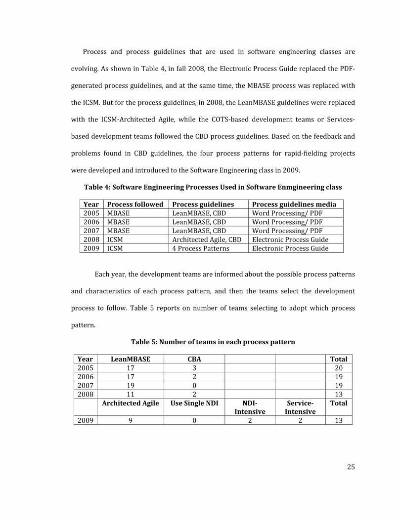
Process and process guidelines that are used in software engineering classes are
evolving. As shown in Table 4, in fall 2008, the Electronic Process Guide replaced the PDF‐
generated process guidelines, and at the same time, the MBASE process was replaced with
the ICSM. But for the process guidelines, in 2008, the LeanMBASE guidelines were replaced
with the ICSM‐Architected Agile, while the COTS‐based development teams or Services‐
based development teams followed the CBD process guidelines. Based on the feedback and
problems found in CBD guidelines, the four process patterns for rapid‐fielding projects
were developed and introduced to the Software Engineering class in 2009.
Table 4: Software Engineering Processes Used in Software Enmgineering class
Year Process followed Process guidelines Process guidelines media2005 MBASE LeanMBASE, CBD Word Processing/ PDF 2006 MBASE LeanMBASE, CBD Word Processing/ PDF 2007 MBASE LeanMBASE, CBD Word Processing/ PDF 2008 ICSM Architected Agile, CBD Electronic Process Guide2009 ICSM 4 Process Patterns Electronic Process Guide
Each year, the development teams are informed about the possible process patterns
and characteristics of each process pattern, and then the teams select the development
process to follow. Table 5 reports on number of teams selecting to adopt which process
pattern.
Table 5: Number of teams in each process pattern
Year LeanMBASE CBA Total 2005 17 3 20 2006 17 2 19 2007 19 0 19 2008 11 2 13 Architected Agile Use Single NDI NDI
Intensive Service Intensive
Total
2009 9 0 2 2 13

26
3.2. Hypotheses
The data are collected and analyzed to answer the following hypotheses:
Hypothesis 1: The rapid‐fielding software development teams following the
Incremental Commitment Spiral process model would outperform others using
traditional processes.
To test hypothesis 1, compare between the teams that follow the Incremental Commitment
Spiral Model (2008 – 2009) and the teams that follow traditional processes; in this case it is
LeanMBASE process (2005 – 2007). The following aspects are compared and analyzed:
client satisfaction and percentage of faster time‐to‐market teams.
Hypothesis 2: The rapid‐fielding software development teams using the
Incremental Commitment Spiral process model – Electronic Process Guide (ICSM
EPG) would outperform others using traditional processes guidelines.
Focusing on how the ICSM EPG supports the development team, the following data is
analyzed to compare the difference in personnel effort between the teams that used EPG
and the teams that used word processing/pdf‐generated process guidelines. Additionally, to
analyze the usability and benefits of the EPG, quantitative survey and qualitative interview
are conducted.
Hypothesis 3: The rapid‐fielding software development teams using the
Incremental Commitment Spiral process model – Process Decision Drivers would
outperform others who do not use it.

27
Incidents of the process selection and re‐selection are analyzed to prove that the process
decision drivers assist in process selection. Moreover, a retrospective analysis is performed
to compare the teams that selected the process pattern with no support from the process
decision drivers. Details and rationale of incident changes are also provided.
3.3. Threats to Validity
This section discusses possible validity threats and ways in which the threats can be
reduced.
‐ Inconsistent Effort Reporting: It is possible that there may be inaccurate efforts
reported, so 2 forms of effort reporting will be used, classroom effort reporting system
and a post‐experiment questionnaire.
‐ Inconsistent Client Satisfaction Ratings: In this experiment, team performance can be
measured from client satisfaction or grade received from graders. Some clients are
finicky or exacting than others. Also, some graders are tougher than others. However,
with the close observation, if there is an outlier or non‐corresponding results, the clients
and the graders will be asked for clarification feedback with the follow up qualitative
interview.
‐ Nonrepresentativeness of subjects: Based on the history of the software engineering
class, the participants, with average of not more than 2 years of industrial experience
and an average 12‐hour, non‐collocated work week, are not representative of a software
engineer in the industry. However, the clients and off‐campus students are full‐time
working professionals.

28
‐ Learning curve: The possibility of an imbalanced team and the threat of learning curve
in using these process models could be overcome by providing tutorials and discussion
sessions in order to build the foundations for all participants.
‐ Nonrepresentativeness of projects: Although the target projects need to conform to
fixed semester schedules, this experiment is to some degree representative of fixed‐
schedule industry projects. The projects are small e‐services applications, but will be
developed for real clients with diverse domains, and will use the same COTS or services
that are used in industry projects. Moreover, the process guidelines and decision drivers
will be cross checked with experts in the field for enterprise‐level compatibility.

29
Chapter 4 : Process Patterns in RapidFielding Projects
4.1. Different Opportunities or Risk Patterns in RapidFielding Project
One can consider ready‐made software such as NDI or NCS as an opportunity or a risk
in software development, different opportunities and risk patterns for each project yields
different software processes. As shown in Figure 12, when there is no significant application
NDI that could contribute their functionalities to the final capabilities of the development
project, the project proceeds with default activities in each phase. On the other hand,
consider the second example, when in the Exploration phase, the developers spent a good
amount of effort to explore and find a perfect NDI that satisfied all the win conditions. This
perfect NDI provides an opportunity for the development team to skip or spend little to no
time in the Valuation and Foundations phases since all functionalities and architecture are
provided by the selected NDI, hence the team does not need to spend time in prototyping or
defining the architecture. The team could start populating data or tailoring the NDI as
appropriate in the Development phase and perform early deployment in the operation
phase. In the third and the fourth examples, in the Exploration phase, the development team
found one or several possible combinations of NDIs/NCSs and its interoperability. To
mitigate the risk and to take the NDI/NCS‐driven opportunity; therefore, the team should
spend more effort and time evaluating the NDIs/NCSs and prioritizing their win‐conditions
or their constraints. On the other hand, since NDIs/NCSs provide a majority of the end user
features, the team could spend less time in Foundations and Development‐related efforts

30
and the team could start operation phase as early as possible. Processes in the NDI and NCS
cases might look similar, but the differences are in the details as mentioned in Table 6.
Figure 12: Different Opportunities and Risk Patterns yield Different Processes
4.2. Differences between NDI and Services
Although the Services‐Intensive case is similar to the NDI‐intensive case, they are
different enough to follow different processes. The development team should use different
criteria to consider the possible NDIs and NCSs. Risks from using NDI are different from
risks from NCS. For example, NCS products are always platform and language independent,
but the users have no control over the changes in the next version. On the other hand, most
NDI products are platform dependent, and the users are fully entitled to the version that
they own. Table 6 and Table 7 report summary of the differences between NDI and NCS.
This also provides another reason why the CBD guidelines an imperfect fit with a Services‐
Based development process.

31
Table 6: Differences between NDI and NetCentric Services
Category NonDevelopmental Item [ includes open source, customer
furnished software]
NetCentric Services
Payment • Non‐commercial items usually have no monetary cost
• Expensive initial costs, moderate recurring fee, training fee, licensing arrangement‐dependent
• Not all services are free, mostly pay per transaction
• Low initial costs, moderate marginal cost, duration dependent license
Platform • Specific and limited to specific platform / language
• Generally supported on a subset of platforms or multiple platforms but with different editions
• Platform and language independent • Server and client can work on different platform
• Interaction between machines over a network
Integration • Generally more tightly coupled • Not very flexible on existing legacy systems when proprietary standard is used
• Difficult when it is a platform dependent and different technologies involved in it.
• detailed documentation and on‐site extensive support
• Generally more loosely coupled • Common web standards, flexible, easy to integrate
• Requires internet access • Support forums and API documentation available
• This integration could be done merely in code, without additional installation of external components
Changes • Able to freeze the version, under user control
• Designed for specific use so costly for customization and change
• Change on server side doesn’t impact the client side
• Major releases once in while • Requires end user intervention to upgrade
• Changes are out of developers’ control • Not easy to predict change, cannot avoid upgrade
• The end‐user has the latest version of the service
• Change on the server side can result in the client side
• Minor releases frequently (through patching)
• Does not require end user intervention Extensions • Only if source is provided and the license
permits • Extension must be delivered to and performed at the end‐user’s site
• Custom extensions may not be portable across COTS or compatible with future releases
• Extension is limited to data provided by the web services
• In‐house extension such as wrapper or mashup
• Little control over performance overhead
Evaluation Criteria
• Maintenance, extensibility, scalability, reliability, cost, support, usability, dependency, ease of implementation, maintainability, upgrades, size, Access to source and code‐escrow considerations
• Upfront costs opposed to subscription • Platform compatibility; Feature controllability
• Reliability, Availability, Cost, Available Support, Speed, Predicted longevity of the service provider, release cycle, Bandwidth
• Recurring costs to use of the service and future functionality offered
• Standards compatibility; Feature‐ data controllability

32
Table 6: Continued
Category NonDevelopmental Item [ includes open source, customer
furnished software]
NetCentric Services
Support Services
• Vendor support for integration, training and tailoring/modification sometimes available for a fee
• Help topics or FAQs would likely not be updated after installation
• Upgrades/Patches and data migration support
• Sometimes can be customized for specific user
• Upgrade through purchasing new releases, self‐install
• Support for tailoring/modification, training generally not available
• Help topics would generally be frequently updated; self‐learning
• Usually not customized for specific user • Patching on service provider’s side; mostly does not require installation on client side
Data • Data often stored locally. Backups generally the responsibility of the user
• Data access is generally fast • Possible variety of proprietary formats • May be inflexible for change but more secure
• Platform‐dependent data format • Can process data offline
• Data stored on service host’s servers. Backups by the provider. Introduces privacy and data‐retention
• Data access could be slower since it is internet based
• Common XML using web standard protocols
• Data from different web services can be used by a single client program
• Process data online
Table 7: Differences between NDI and NCS
Characteristics NDI NCS Platform Independent Yes / No Yes Required Internet Access Yes / No Yes Common Standard No Yes Option of rejecting next release Yes No Change / upgrade control Client /Server’s site Server’s site End user has the latest version Yes / No Yes Database Ownership Yes Yes/No
4.3. RapidFielding Project Characteristics
Given a project description, one may not know whether to follow a general waterfall or
agile development process or if it needs to adopt different development processes. Table 8
summarizes general characteristics for each rapid‐fielding process pattern. As shown in the
table, NDI‐intensive process pattern that requires NDI‐driven architecture and NDI‐
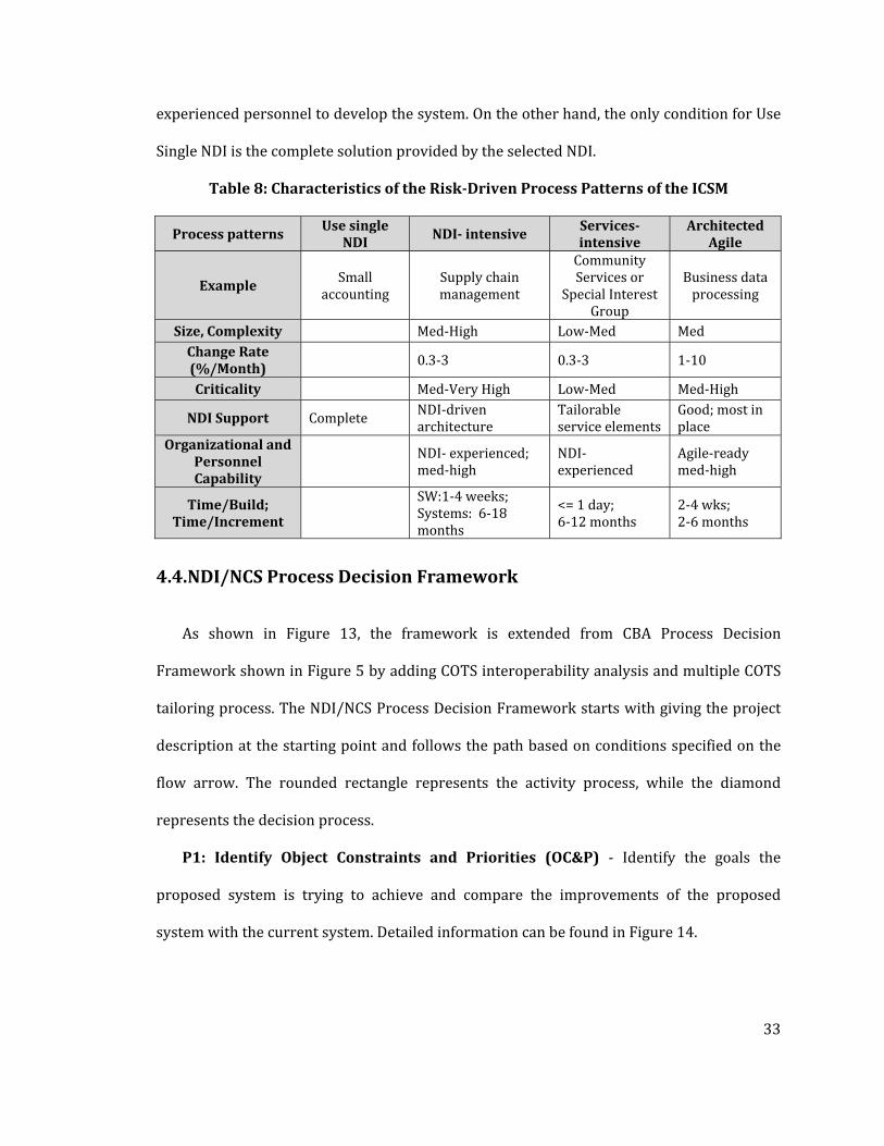
33
experienced personnel to develop the system. On the other hand, the only condition for Use
Single NDI is the complete solution provided by the selected NDI.
Table 8: Characteristics of the RiskDriven Process Patterns of the ICSM
Process patterns Use single
NDI NDI intensive Servicesintensive
Architected Agile
Example Small
accounting Supply chain management
Community Services or
Special Interest Group
Business data processing
Size, Complexity Med‐High Low‐Med Med Change Rate (%/Month) 0.3‐3 0.3‐3 1‐10
Criticality Med‐Very High Low‐Med Med‐High
NDI Support Complete NDI‐driven architecture
Tailorable service elements
Good; most in place
Organizational and Personnel Capability
NDI‐ experienced; med‐high
NDI‐ experienced
Agile‐ready med‐high
Time/Build; Time/Increment
SW:1‐4 weeks; Systems: 6‐18 months
<= 1 day; 6‐12 months
2‐4 wks; 2‐6 months
4.4. NDI/NCS Process Decision Framework
As shown in Figure 13, the framework is extended from CBA Process Decision
Framework shown in Figure 5 by adding COTS interoperability analysis and multiple COTS
tailoring process. The NDI/NCS Process Decision Framework starts with giving the project
description at the starting point and follows the path based on conditions specified on the
flow arrow. The rounded rectangle represents the activity process, while the diamond
represents the decision process.
P1: Identify Object Constraints and Priorities (OC&P) ‐ Identify the goals the
proposed system is trying to achieve and compare the improvements of the proposed
system with the current system. Detailed information can be found in Figure 14.

34
P2: Do relevant NDI/Services exist? – Given the OC&P, explore all possible related
alternatives, such as commercial products, freeware, open source software, reuse library,
reuse component, or web service. It is possible that one product could satisfy all desired
functionalities, or it could be a combination of multiple products. To support the NDI/
Services selection, gather all available information such as functionalities and costs.
Figure 13: NDI Process Decision Framework

35
Figure 14: Identify OC&Ps and explore alternatives
P3: Can adjust OC&Ps? – One of the main differences between Architected Agile
process and NDI/NCS process is that the NDI/NCS process does not start with
requirements, but with OC&Ps. If there is no application NDI/Services that could contribute
the functionalities to the final product deliverable, or there are some NDI/services that
conditionally satisfy the win conditions. The development should discuss with all critical
stakeholders to adjust the OC&Ps to accommodate the possible NDI/services.
P4: Custom Development – If the OC&Ps are not adjustable, follow the Architected
Agile process
P5: Assess NDI/Services Candidates ‐ With the possible alternatives, use objectives,
constraints, and priorities to establish weights for all NDI/NCS Attributes. To assign
weights, all team members should talk to the client to find out about how important each
attribute is. Examples of NDI features are report module, discussion board module
and show pictures/vdo module. Initial assessment attempts to quickly filter out the

36
unacceptable COTS packages with respect to the evaluation criteria. The objective of this
activity is to reduce the number of NDI/Services candidates needing to be evaluated
in detail. If no available NDI/Services products pass this filtering, this assessment element
ends up at the “no acceptable NDI/Service Based Solution,” and continues with P3: Adjust
OC&Ps. Detailed information is shown in Figure 15.
P6: Multiple NDI/Services Solution? – Since there is a risk in using multiple
NDIs/services, the development team should put extra effort in checking component
interoperability when considering multiple NDI/services.
P7: Check interoperability – The iStudio tool [Bhuta 2007] from COTS Interoperability
Assessment Framework is used to identify the possible components mismatch. Detailed
information is described in Figure 16.
P8, P10: Tailoring Required? – Either in a case of using a single NDI/Service, or
multiple NDIs/ Services, the development team must check whether the NDI/service needs
to be tailored to satisfy the requirements.
P9: Tailor a single NDI/Service, P11: Tailor multiple NDI/Services – When a certain
NDI product satisfies all of the requirements, there is no need to develop custom code or
glue code. But, the selected NDI product or a web service may need to be tailored in order to
provide proper functionalities for the specific system context. More details can be found in
Figure 17 and Figure 18.
P12: Custom Code Required? – The development team should identify the missing
functionalities that the NDI/ Services do not provide, then develop additional functionalities
or coding in order to satisfy the requirements. The functionalities are derived from
stakeholders' win conditions and capability goals.

37
P13: Develop Custom Code – The architecture of each component is modeled in the
software architecture document. Compared to Architected Agile process, it may be more
challenging to identify the component architecture for NDI/ services because, frequently,
the NDI/Service architecture is unknown. One way to mitigate the risk of component
mismatch is to check for components’ interoperability or develop the prototype for
component integration. The development team should identify which components will be
developed in which iteration in an/the Iteration Plan.
P14: Glue Code Required? – When there is more than one component needed in the
project development, it is highly likely that the glue code needs to be developed.
P15: Develop Glue Code ‐ To develop interface between Non‐Development‐Item or
Services and other components. More information can be found in Figure 19.
P16: Productize, Test, and Transition – After all components are ready and
integrated, the development team should thoroughly test the product by using both
verification and validation techniques. Furthermore, the team should prepare for transition,
such as data preparation, site preparation, and human resource preparation.
P1.1 P2: Identify OC&Ps and explore alternatives – As shown in Figure 14, various
inputs can be used to support the OC&P identification. The output of this process is the
candidate NDIs/Services, which could be a single NDI/Service or a combination of
NDIs/Services.
• Identify Capability Goals ‐ Provide a brief enumeration of the most important
operational capability goals. A “capability” is simply a function or set of
functions that the system performs or enables users to perform.
• Identify Level of Service Goals ‐ Identify the desired and acceptable goals for
the proposed new system's important levels of service, or in other words, the

38
system's quality attributes or “‐ilities.” Capability goals address what the
system should do: level of service goals address how well the system should
perform. Indicate the desired and acceptable levels of service of the new system
• Identify Organizational Goals ‐ List briefly the broad, high‐level objectives
and aspirations of the sponsoring organization(s) and any organizations that
will be using and maintaining the new system.
• Identify Constraints ‐ Identify constraints of the project. Constraints will be
derived from your WinWin negotiation and/or client meetings. Constraint is a
limitation condition that you have to satisfy when selecting or evaluating the
NDI/NCS or developing the system. Examples of Constraints are CO‐1:
Windows as an Operating System: The new system must be able to run on
Windows platform or CO‐2: Zero Monetary Budget: The selected NDI/NCS
should be free of or have no monetary cost.
• Compare to Current System ‐ Summarize the relations between the current
and new systems in a table. Include key differences between the current and
new roles, responsibilities, user interactions, infrastructure, stakeholder
essentials, etc.
After reading a project proposal, the development team should investigate
alternatives in the development project. Quite often, an appropriate NDI (s) (COTS, open
source, reuse library, customer‐furnished package) solution or partial solution is available.
Even if a better solution is produced (frequently not the case), more expense and longer
time to capitalize on its benefits will result. Oftentimes, the NDI package has features that
one hadn’t realized would be needed, but are there when one needs them.

39
• Check project objectives – Analyze project proposal, identify the project
objectives.
• Check win conditions constraints and priorities ‐ After WinWin Negotiation,
study all the win conditions, especially capability / product win conditions and
level of service win conditions; use them to investigate or explore possible
NDI/NCS solutions.
• Check proposed new operational concept – Consider what has been
proposed to the client, how can their business work flow change or how will
you new technologies or any improvement to the project be introduced.
• Perform initial check in NDI/ Service list ‐ Look at the commonly used
components in List of NDI and Service, check whether there any component can
be used in the project.
• Search for candidate NDI/Services –Search for possible NDI/Service
components in the market both in the commercial product sector and the free
product sector.

40
Figure 15: Assess NDI/Services Candidates
P5.1 –P5.7 Assess NDI/ Services Candidates – With the possible alternatives, the
development should evaluate each alternative solution based on the given Objectives,
Constraints, Priorities (OC&P)
• Establish evaluation criteria, weights by using NDI/NCS attributes ‐ After the
task of identifying Organizational and Operational Transformation, use objectives,
constraints, and priorities from the Operational Concept Description document to
establish weights for each NDI/NCS Attribute. To assign weights, all team members
should talk to the client to find out how important each attribute is.
• Establish evaluation criteria, weights by using NDI/NCS features ‐ After the task
of Identify Organizational and Operational Transformation, use objectives,
constraints, and priorities from the Operational Concept Description document to
establish weights for each NDI/NCS feature. Examples of NDI features are report
module, discussion board module and show pictures/vdo module. To assign

41
weights, all team members should talk to the client to find out how important each
attribute is.
• Perform initial filtering ‐ Initial assessment tries to filter out the unacceptable
COTS packages quickly with respect to the evaluation criteria. The objective of this
activity is to reduce the number of COTS candidates needing to be evaluated in
detail. If no available COTS products pass this filtering, this assessment element
ends up at the “none acceptable” exit.
• Perform product line and market trend analysis Briefly analyze the market
trend, product popularity, product market standpoint, predicted longevity of the
company, and etc. Also, analyze the related products that are developed/ launched
by the same company/ organization. For example, if a company has been in the
market for quite some time, and this company is very popular for the product that
you are considering, this component may get a higher score or higher credit.
• Perform tradeoff analysis Compare scores from each evaluation criteria, market
trend and product line and analyze pros and cons for each component or component
combination.
• Acquire NDI / Services After scoping down or filtering out the alternatives, you
should have a small list of potential components or component combination. If the
component is available to download or install, either in a trial version, open source
version, or free version, you should acquire and try to use it. If the candidate
component is not free for trial, it is you and your client's decision whether you need
to have hands on for that particular component.

42
• Perform trial run When the component or the component combination is
available, try to use the functionalities that will be required or related to the project
scope.
• Analyze assessment results Data and information about each COTS candidate are
collected and analyzed against evaluation criteria in order to facilitate trade‐offs and
decision making. In this step, a screening matrix or analytic hierarchy process is a
useful and common approach to analyze collected evaluation data.
P7.1 – P7.4: Check Interoperability – When there is more than one component
involved in the project, the development must be active in mitigating the component
mismatch risk by checking whether the components are interoperable. This might not be a
case for NCS because the components are platform independent, and they use the standard
XML to communicate among components.
• Check NDI/NCS based architecture ‐ One should have a draft system architecture
that identifies the potential system structure, use case, artifacts, hardware and
software.
• Identify potential NDI/NCS component combinations ‐ Identify all the possible
choices of the NDI/service and/or their combination.
• Analyze NDI/NCS based architectures ‐ Use iStudio to analyze the interoperability
of finding mismatches between your architecture and component combination
choices.
• Evaluate NDI/NCS assessment report ‐ Evaluate the result reported from iStudio,
recheck the potential mismatches, and find the best alternative architecture.

43
Figure 16: Check Interoperability
Figure 17: Tailor a single NDI/ Service

44
Figure 18: Tailor multiple NDI/Services
P9.1 – P9.4, P11.1 – P11.4 Tailor NDI/Services ‐ When a certain NDI product can
satisfy all the requirements, there is no need to develop application code or glue code. But
the selected NDI product may need to be tailored in order to work for the specific system
context.
• Identify tailoring methods ‐ Tailoring options include GUI operations, parameter
setting, or programming specialized scripts. An NDI / NCS product may have
multiple tailoring options; in such cases the decision must be made as to what
capabilities are required to be implemented by which option. Tailoring options may
include GUI operations, parameter settings, or programming specialized scripts.
• Perform tailoring effort or functionality tradeoff analysis When there is no
single best choice of tailoring method, the team must perform trade‐off analyses
between the effort required by available tailoring methods and the functionality that
the team hopes to achieve via tailoring. It is not uncommon, even in the same
product domain, for tailoring effort to significantly vary depending upon the
45
NDI/NCS package selected. Automated tools, such as Microsoft Excel’s macro
recorder can significantly reduce the tailoring effort. Another factor that the teams
must consider whilst performing the tradeoff is the amount of re‐tailoring that will
be required during a NDI/ NCS refresh cycle. The integration of COCOTS cost
estimation model provides a supporting mechanism to perform this type of tradeoff
analysis through its Tailoring sub model parameters. More specifically, the Tailoring
Complexity Quantifier in COCOTS Tailoring sub model evaluates the required
amount of effort to implement a particular design, the complexity of tailoring
needed, and the need for adaptability and compatibility with other COTS tailoring
choices. Then, the developers can make decisions based on available resources.
• Design and plan tailoring using best available tailoring method While tailoring
may be straightforward for non‐distributed, single‐solution systems, it can be
extremely complex for large distributed applications, such as Enterprise Resource
Planning packages. In such cases it is recommended that teams plan the tailoring.
Formats of planning may vary from a simple checklist of steps to a complete set of
UML diagrams (programmable tailoring).
• Perform tailoring Tailor the NDI/NCS component based on the defined tailoring
method.

46
Figure 19: Develop Glue Code
P15.1 – P153: Develop Glue Code In order to get the service provided by NDI or
to be able to integrate NDI to the system or to integrate the multiple NDIs, one must develop
some code to interface or coordinate with NDI, so that the NDI can properly pass the data to
other software components, which could be another NDI or a component that is developed
from scratch.

47
4.5. Work Breakdown Structure in RapidFielding Process
This section elaborates on overall tasks and corresponding artifacts in each phase for
rapid‐fielding projects based on the ICSM process. First, as shown in Figure 20, Exploration
phase, tasks can be categorized into 3 main groups a) Project Exploration, focuses on
understanding the current project and identifying possible solutions; b) WinWin
Negotiation, focuses on gathering and negotiating win conditions from all success critical
stakeholders; and c) Project Management, focuses on planning and allocating tasks to the
appropriate stakeholders. The results of the tasks are recorded in various artifacts, such as
Operational Concept Description (OCD), Feasibility Evidence Description (FED), Distributed
Assessment of Risks Tool (DART), Project Plan, and Progress Report. Generally, the
development team selects the process pattern once they have enough information about the
project, which is either the end of the Exploration phase or the beginning of the Valuation
phase. As a result, all of the tasks in the Exploration phase are similar for all 4 process
patterns.
Figure 20: Delivery Process in Exploration Phase

48
In the Valuation phase, as shown in Figure 21, a blue rounded rectangle represents a
task that is specifically required for Architected Agile, while a red dashed rounded rectangle
represents a task that is required for NDI/NCS process. The green dotted rounded rectangle
represents special case consideration for Use Single NDI process pattern. With the ICSM
process, all projects proceed with similar activities. Some process patterns may spend extra
effort focusing on a particular task. For example,
‐ One of the major propositions for the NDI/services‐intensive process is “do not start
with the requirements” [Yang 2006] but use the win conditions as the starting point to
assess the component alternatives. On the other hand, the architected agile process, as
highlighted in the blue rectangle task, translates the win conditions into requirements
and proceeds to prototyping or defining architecture based on the agreed requirements.
‐ Assess and Acquire NDI/NCS – for the NDI/Services‐intensive project, the development
should spend more time assessing and evaluating the alternatives as mentioned in
Figure 15.
‐ Define Architecture – the NDI/Services‐intensive project and the Architected Agile
project will focus on architecture in different a perspective. While the Architected Agile
focuses on determining a technology‐independent model followed by technology‐
specific model, the NDI/Services team focuses on analyzing the components
interoperability.
‐ Detail Life Cycle Approach – cost estimation is one of the key activities in project
management; the Architected Agile team uses COCOMO II to support the cost
estimation, while the NDI/Services team uses COCOTS.
‐ Analyze Business Case – to provide project feasibility evidence, every project should
consider investigating cost analysis, benefit analysis, and return on investment analysis.

49
Additionally, the NDI/Service team should spend extra effort to analyze the market
trend and product line of the alternative solution.
Figure 21: Delivery Process in Valuation phase
In the Foundations phase, Figure 22, the development team should focus on building
all the required foundations, such as system and software architecture, developing
prototype, especially on the functionalities that need clarification or have high risks, and
providing other project feasibility evidence such as business case analysis. For the
NDI/Services‐intensive project, since most of the functionalities are provided by
NDI/Services, and oftentimes their architecture in not known, the development team can
spend less effort in this phase.

50
Figure 22: Delivery Process in Foundations phase
Figure 23: Development phase Construction increment

51
Generally there is more than one increment in the Development phase, Figure 23,
the tasks are similar in all rapid‐fielding process patterns, but the differences are in the
details of each task. Usually, less effort is needed for the NDI/Services project to reach this
phase since it takes less effort to complete the Foundations phase.
For the Transition increment, Figure 24, if there is a commercial NDI used in the
project, training and transition could be provided by the company. NDI products generally
provide better user manuals or customer support to the buyer. On the other hand, most of
the web service provider companies do not provide user manuals or training, but there
could be some online discussion board or group website that provides supporting
information. Hence, the development team should prepare for transition by preparing the
deployment environment, provide training the end users, and prepare all necessary
supporting materials.
Figure 24: Delivery Process in Development phase Trnaition increment
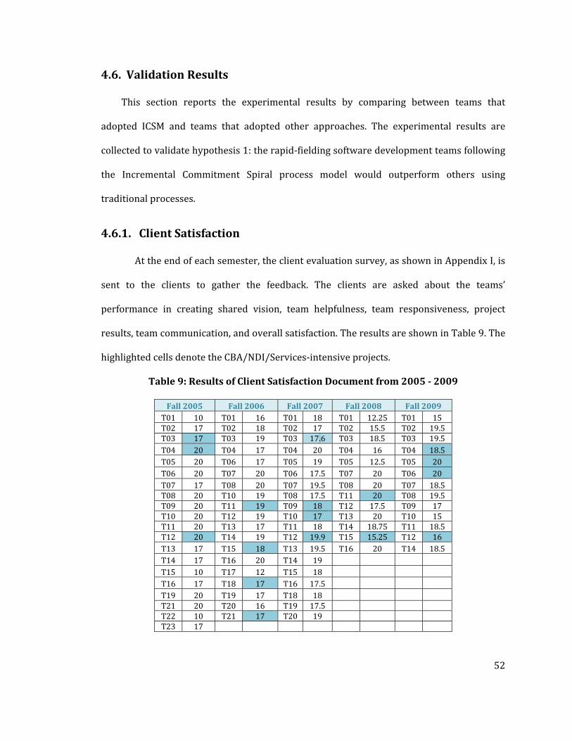
52
4.6. Validation Results
This section reports the experimental results by comparing between teams that
adopted ICSM and teams that adopted other approaches. The experimental results are
collected to validate hypothesis 1: the rapid‐fielding software development teams following
the Incremental Commitment Spiral process model would outperform others using
traditional processes.
4.6.1. Client Satisfaction
At the end of each semester, the client evaluation survey, as shown in Appendix I, is
sent to the clients to gather the feedback. The clients are asked about the teams’
performance in creating shared vision, team helpfulness, team responsiveness, project
results, team communication, and overall satisfaction. The results are shown in Table 9. The
highlighted cells denote the CBA/NDI/Services‐intensive projects.
Table 9: Results of Client Satisfaction Document from 2005 2009
Fall 2005 Fall 2006 Fall 2007 Fall 2008 Fall 2009 T01 10 T01 16 T01 18 T01 12.25 T01 15 T02 17 T02 18 T02 17 T02 15.5 T02 19.5 T03 17 T03 19 T03 17.6 T03 18.5 T03 19.5 T04 20 T04 17 T04 20 T04 16 T04 18.5 T05 20 T06 17 T05 19 T05 12.5 T05 20 T06 20 T07 20 T06 17.5 T07 20 T06 20 T07 17 T08 20 T07 19.5 T08 20 T07 18.5 T08 20 T10 19 T08 17.5 T11 20 T08 19.5 T09 20 T11 19 T09 18 T12 17.5 T09 17 T10 20 T12 19 T10 17 T13 20 T10 15 T11 20 T13 17 T11 18 T14 18.75 T11 18.5 T12 20 T14 19 T12 19.9 T15 15.25 T12 16 T13 17 T15 18 T13 19.5 T16 20 T14 18.5 T14 17 T16 20 T14 19 T15 10 T17 12 T15 18 T16 17 T18 17 T16 17.5 T19 20 T19 17 T18 18 T21 20 T20 16 T19 17.5 T22 10 T21 17 T20 19 T23 17

53
Comparing LeanMBASE years and ICSM years, as shown in Table 10, the median of
the point lost from the client satisfaction of Architected Agile team has shown that the
teams that adopt the ICSM outperformed the teams that did not adopt the ICSM. On the
other hand, considering the CBA/NDI/NCS process, with the exception of 2005, the teams
that follow ICSM outperformed the teams that followed CBD process guidelines.
Additionally, consider the results from Table 11, without categorizing by year, the client
satisfaction score has shown that the clients prefer the deliverables from the projects that
follow ICSM. Hence, the teams that follow ICSM process guidelines also outperformed the
LeanMBASE and CBD Teams.
With the null hypothesis that the ICSM teams does not outperform the LeanMBASE/
CBA teams in term of client satisfaction, with 5% significant level, P‐value is 0.471099,
hence there is not enough evidence to reject the null hypothesis and it indicates that these
means are not statistically significant.
Table 10: Analysis results of Points lost on Client satisfaction
Semester Process Guidelines
Architected Agile teams
Process Guidelines
CBA/NDI/NCS teams
Fall 2005 LeanMBASE 3 CBD 0 Fall 2006 LeanMBASE 2 CBD 2.5 Fall 2007 LeanMBASE 2 CBD 2.2 Fall 2008 ICSM 1.5 CBD 2.4 Fall 2009 ICSM 1.5 ICSM 0.8
Table 11: Comparison of Point Lost from Client Satisfaction
DoF = 62, P‐Value = 0.471099 Median SD
LeanMBASE, CBD Teams 2 2.38 ICSM Teams 1.5 2.37

54
4.6.2. Faster Time to Market Projects in Software Engineering Class
One of the main objectives of rapid‐fielding projects is to launch the product or
deploy the product as soon as possible. The ICSM process model highly supports the
process users to make a value‐based decision on how to emphasize and de‐emphasize tasks
and activities or the process itself based on project opportunities and risks. With
LeanMBASE and COTS‐Based Development process models, the risk‐based decision points
are not properly articulated. Hence, various teams did not have a chance to take
opportunities to launch the product as quickly as they could. In USC’s Software Engineering
class, the projects usually take 12 weeks in the fall semester and 12 weeks in the spring
semester to develop. At the end of fall semester, various teams come up with the most
appropriate COTS, NDI or NCS for the clients to make decisions. Some teams go further with
the partial populated data with deliverables that are ready to transition to the clients to
finish tailoring or complete the data transfer which is semi‐deployable project. Some other
teams go even further by delivering the products that are ready to run. Table 12 shows the
percentage between the teams that deliver deployable products and the teams that deliver
semi‐deployable products. The ICSM teams outperformed the LeanMBASE and CBD teams
considering the factor of time‐to‐market product.
Table 12: Percentage of teams that deliver Faster TimeToMarket projects
Prepare to transition
after 12 weeks Deployable
after 12 weeks Total
LeanMBASE, CBD 11% 5 % 16%ICSM 14% 18% 32%

55
4.6.3. Conclusion
Regarding the Hypothesis 1: The rapid‐fielding software development teams following
the Incremental Commitment Spiral process model would outperform others using
traditional processes, with the client satisfaction and percentage of faster time‐to‐market
projects, it is clearly shown that the ICSM teams outperformed the LeanMBASE and CBD
teams.
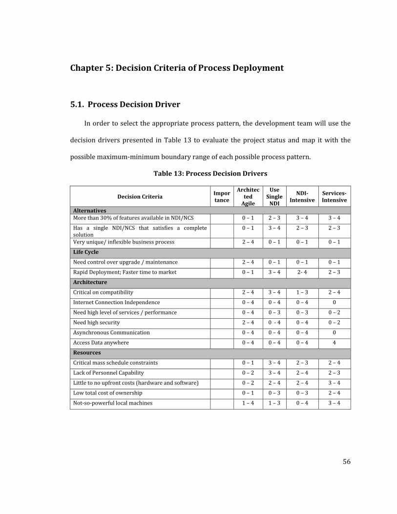
56
Chapter 5 : Decision Criteria of Process Deployment
5.1. Process Decision Driver
In order to select the appropriate process pattern, the development team will use the
decision drivers presented in Table 13 to evaluate the project status and map it with the
possible maximum‐minimum boundary range of each possible process pattern.
Table 13: Process Decision Drivers
Decision Criteria Importance
Architected Agile
Use Single NDI
NDIIntensive
ServicesIntensive
Alternatives More than 30% of features available in NDI/NCS 0 – 1 2 – 3 3 – 4 3 – 4
Has a single NDI/NCS that satisfies a complete solution
0 – 1 3 – 4 2 – 3 2 – 3
Very unique/ inflexible business process 2 – 4 0 – 1 0 – 1 0 – 1
Life Cycle
Need control over upgrade / maintenance 2 – 4 0 – 1 0 – 1 0 – 1
Rapid Deployment; Faster time to market 0 – 1 3 – 4 2‐ 4 2 – 3
Architecture
Critical on compatibility 2 – 4 3 – 4 1 – 3 2 – 4
Internet Connection Independence 0 – 4 0 – 4 0 – 4 0
Need high level of services / performance 0 – 4 0 – 3 0 – 3 0 – 2
Need high security 2 – 4 0 ‐ 4 0 – 4 0 – 2
Asynchronous Communication 0 – 4 0 – 4 0 – 4 0
Access Data anywhere 0 – 4 0 – 4 0 – 4 4
Resources
Critical mass schedule constraints 0 – 1 3 – 4 2 – 3 2 – 4
Lack of Personnel Capability 0 – 2 3 – 4 2 – 4 2 – 3
Little to no upfront costs (hardware and software) 0 – 2 2 – 4 2 – 4 3 – 4
Low total cost of ownership 0 – 1 0 – 3 0 – 3 2 – 4
Not‐so‐powerful local machines 1 – 4 1 – 3 0 – 4 3 – 4

57
The combination of 16 process decision criteria is used to identify the appropriate
process pattern.
Alternatives
• More than 30% of features available in NDI/NCS – An NDI‐intensive or a
services‐intensive system is a system for which at least 30% of the end‐user
functionality is provided by NDI or Services products. Hence, the NDI‐Intensive and
Service‐intensive process will get a high score range (3‐4). On the other hand, the
Architected Agile process pattern will get low score range (0‐1) since it has low
compatibility with this criteria.
• Has a single NDI/NCS that satisfies a complete solution – if there is an NDI that
satisfies all required functionalities, the development team should follow Use Single
NDI process pattern.
• Very unique/ inflexible business process – if the business process is very unique,
there are fewer chances that there will be ready‐to‐use software or NDI/Services
that would fit the unique business process. So, the development team should
distinguish between essential and negotiable requirement and be flexible where
they can; otherwise, the development team should follow the Architected Agile
process pattern.
Life Cycle
• Need control over upgrade / maintenance – one of the disadvantages of web
services or net‐centric services is the user’s inability to avoid the changes made to
the product. The updates are done at the server side, and the client automatically
receives the service based on the deployed version from the server. The users do

58
not have to worry about the software maintenance at all since it is beyond their
capability. On the other hand, for NDI, the users are allowed to stick with the current
version that they owned. Additional concerns with NDI are vendors who promise
but don’t deliver and products that don’t work as advertised. As a result, if one of
the win conditions of the project is to control the evolution of the product, the
architected agile process pattern should be selected.
• Rapid Deployment; Faster time to market ‐ When an appropriate NDI (COTS,
open source, reuse library, customer‐furnished package) solution is available, it is
an option to either use the NDI or develop a better version by oneself or outsource
such a development, which generally incurs more expense and takes longer to begin
capitalizing on its benefits. If one of the project goals is to market quickly, consider
using NDI or services.
Architecture
• Critical on compatibility – component mismatch is one of the major risks in NDI‐
intensive projects because most NDIs are platform dependent and have unique
output format. The development team should pay closer attention to component
interoperability if component compatibility is the major concern in the project.
Using Single NDI and Services‐Intensive are the most appropriate process patterns
since Use Single NDI requires only one NDI, and web services have standard
communication protocol.
• Internet Connection Independence – Communication through the internet is a
mandatory ingredient for Services‐intensive project. If the internet connection may
not be available during deployment, the development should not select Services‐
Intensive process pattern. For Use Single NDI process pattern, the development
59
team should assess the product clearly, whether it is able to work properly without
an internet connection.
• Need high level of services / quality characteristics – Examples of Level of
Services or quality characteristics are availability, reliability or Mean‐Time‐
Between‐Failure, and speed. One of the major drawbacks of services‐intensive is
they do not guarantee the level of services, so, if the project is critical for certain
performance, the development team should either develop the functionalities from
scratch or select the NDI that guarantees the desired level of performance.
• Need high security – Security is another weak point of Web Services. If the project
requires very high levels of security, the development team should consider
adopting Architected Agile, where the development can develop high security
components or adopting Use Single NDI or NDI‐Intensive if the products provide
acceptable levels of security.
• Asynchronous Communication – Web services only work under synchronous
communication. Hence the development team should select Use Single NDI or NDI‐
Intensive if the project requires offline processing and the product provides
asynchronous communication capability. Otherwise, the team should adopt
Architected Agile process pattern.
• Access Data anywhere – Various NDIs provide access only from local machines;
hence, the development team should spend more time to assess the alternatives for
a global access option of a potential NDI. Otherwise, Services‐intensive or
Architected Agile are the most appropriate process patterns in this case.
Resources

60
• Critical mass schedule constraints – With the ready‐to‐use functionalities from
NDI or Web Services, the development team does not have to spend time
reinventing the wheel. So, if faster time‐to‐market is the key condition, the
development should highly consider Use Single NDI or NDI/Services‐intensive
process pattern.
• Lack of Personnel Capability – Most of the NDIs come with user manuals or user
support teams, and most of the web services provide discussion boards from which
the users or the maintainers can obtain more information about the product or the
solution if the product has a problem. On the other hand, if the development team
develops products from scratch with a lean version of a user manual, the non‐
technical maintainer might not be able to maintain or keep the product to work
properly. Hence, if the users do not have enough technical knowledge to maintain
the product, it is more appropriate to select Use Single NDI, NDI/Services‐intensive
process patterns.
• Little to no upfront costs – Web services only require a computer and internet
connection to run, and most of the web services available are free; hence, very little
upfront costs on both hardware and software are needed. Not all NDIs are free, so
the development team needs to compromise between the cost of potential NDI and
their functionalities. The upfront cost of Architected Agile process depends on
choices of the selected software and hardware.
• Low total cost of ownership – Other than hardware and software costs, possible
costs of NDI include recurring fees, training fees, and licensing fees. Net‐Centric
services usually have lower initial costs and moderate marginal costs; other possible
costs include transaction fees or licensing fees. Architected Agile is more expensive

61
in terms of effort, time, and possible required hardware and software required for
development; hence, if the budget is limited, the preferred choices should not be
Architected Agile Process Pattern.
• Notsopowerful local machines – Net‐Centric Services do not require high
powerful local machines since the services are processed at the server machine.
Various NDIs require different kinds of local machine specification, but in many
cases, NDI requires at least one powerful machine to act as a server machine.
The score of each category ranges from 0‐Low to 4‐High; the range of scores for each
process pattern for each criteria is used to create process pattern templates. As shown in
Figure 25, the range of rating scale for Architected Agile is translated to a block template.
For example, the first criteria, more than 30% of features available in NDI/NCS, the
Architected Agile with rating score range 0‐1 is mapped to the 0‐1 block pattern in the
template. As a result, there are 4 templates for each process pattern, which can be found in
Appendix H.

62
Figure 25: Translating Rating Scales to Process Template
The development team together and the success‐critical stakeholders evaluate the
project status and assign a rating score in each decision criteria. The value of project status
ranges from 0‐Very Low, 1‐Low, 2‐Moderate, 3‐High, and 4‐Very High. Additionally, the
development team and the stakeholders should also define the “Importance” attribute,
whose values are 1‐Low, 2‐Medium, 3‐High to represent how significant each criterion is in
regard to the project. This ranking will act as a tie breaker to support decision making in
selecting the best fit process pattern. Figure 26 shows an example of a team that is
developing a simple website. The team found a possible content management system NDI,
but it does not satisfy all of the capability win conditions. The team rates the project status
based on 16 decision drivers, the result is shown with the blue line. The background block

63
diagram is the max‐min boundary of NDI‐Intensive project. The red underline represents
High Importance level, while the green underline represents Low Importance level. As a
result, the decision driver shows that this team could follow the NDI‐intensive software
development process. More examples can be found in Appendix D.
Figure 26: An Example of Using Decision Drivers to map with an NDIIntensive Project
The second example, Figure 27, shows how a team rates its project status and
compares it with each process pattern template. The blue line represents the project status
on 16 decision criteria. The red and dashed green lines represent importance level. The
development team plots the project status line and importance choice on each process
template. The red dot represents a nonconforming point where the project status is outside
the process pattern block. To select an appropriate process pattern, the development team
should select the process pattern that has the least number of non‐conforming points. As
shown in Figure 27, there is only one nonconforming point when the team plots the project
status on Architected Agile process pattern, and the nonconforming point is not located on
high importance criteria. On the other hand, there are 8 nonconforming points found in Use

64
Single NDI process pattern, 6 nonconforming points found in NDI‐intensive process pattern,
and 12 nonconforming points found in Services‐intensive process pattern. Therefore, in this
case, the development team can conclude that they should follow the Architected Agile
process pattern.
Figure 27: Example of Process Pattern Selection
If there are equal numbers of nonconforming points, the development team should
consider the nonconforming point found in the high important decision criteria and discuss
with critical stakeholders to choose the most appropriate process pattern or renegotiate
win conditions.
5.2. Discussion with Field Experts
Three experts in the software industry are selected based on their experience in rapid‐
fielding projects. The first expert is Mr. Len Cayetano, president at Cayetano Technology
Group. He was a director of software engineering at SOA Software. The second expert is Dr.

65
Srinivas Padmanabhuni, principal research scientist, SETLabs, Infosys Technologies Ltd.
The third expert is Mr.Neil Seigel, Sector Vice President and chief engineer of Northrop
Grumman Corporation. During the interview, the background of the research and the
concept of the ICSM including four patterns of rapid‐fielding projects are presented. The
experts are interviewed to verify the correctness and the representativeness of the process
decision drivers. The experts agree that these process decision drivers can be used to
support the development teams to select the process pattern. One of the experts suggests
that Asynchronous Communication should be added to the list since web‐services do not
work under asynchronous communication. Another suggestion is to run the process
decision drivers, not only in the classroom environment, but in the industry environment,
which is part of the future research. The last expert who is familiar with large scale rapid‐
fielding projects explained that there are 2 main criteria that are very important to process
pattern consideration, which are a) quality characteristics such as availability and reliability
and b) capability. This feedback confirmed that the process decision drivers cover main
decisive factor for process pattern selection.
5.3. Process Adoption
After the development teams brainstormed all of the win conditions with all success
critical stakeholders; identified objectives, constraints and priorities; identified the shared
vision; analyzed the current system; and explored the possible alternatives, the
development teams will have an overview of the project status. The development teams use
the process decision drivers to select the process pattern.
Based on the survey results, the process decision drivers help the teams to select the
most suitable process pattern. Moreover, when the scope or status of the project changes,

66
the development teams found it useful to reconfirm or to re‐identify the process pattern
with the process decision drivers.
5.3.1. Incidents of Process Selection and Direction Changes
The process decision driver is introduced in fall 2009, 14 projects selected their process
pattern by using the process decision drivers. Comparing the result of the teams’ process
selection by using process decision drivers with the experts’ opinion from the architecture
review board
• 8 out of 14 teams selected the right process pattern from beginning of the Valuation
phase as shown in Figure 28. Based on the risk analysis at the end of each milestone,
some teams found NDI or NCS, so they can skip certain phases, while some other
teams proceed to their appropriate directions.
Figure 28: Result of right process pattern selection
• 3 out of 14 teams, Figure 29, selected wrong process pattern because of unclear
project scope, but after discussing and gathering more information from the success
critical stakeholders, exploring more alternatives and conducting additional
prototyping, the teams found that the selected NDIs/Services do not provide the
required functionalities. As a result, with the updated project status, the teams

67
reevaluated their process patterns and reselected the process after briefly repeating
the exploration phase.
Figure 29: Results of incorrect process selection due to unclear project scope
• As shown in Figure 30, one team faced the minor but acceptable changes from the
critical success stakeholders; after the renegotiation, the development team found
that the selected services do not fit with the project; hence, the team moved on the
develop the project from scratch by using the win conditions gathered in the
Exploration phase and start prioritizing the requirements based by using value‐
based requirements negotiation approach. Also the team reselected and followed
different process pattern.

68
Figure 30: Result of incorrect process selection due to minor changes
• One team selected the Architected Agile process and proceeded from Exploration to
Foundations phases. During the Development phase, the team found that there were
applicable Net‐Centric Services. Hence, the team re‐selected the process pattern to
Services‐Intensive process pattern and went back to the Exploration phase to
perform detailed assessment and bypass the Valuation and Foundations phases
since the selected NCS provides most of the required functionalities, as displayed in
Figure 31.
Figure 31: Results of Process ReSelection due to available NCS

69
• One project followed the correct process pattern but found that the client’s
requirements were infeasible within a defined budget and schedule; hence, the team
proposed the feasible solution and had to switch to other process pattern, as shown
in Figure 32.
Figure 32: Result of infeasible project
5.3.2. Incidents of Wrong Process Selection
Before the process selection drivers were introduced in fall 2009, the development
team did not pay attention to the selected process pattern and did not have any chance to
consider their project status. The following teams followed the Architected Agile process
patterns, but they should have followed Cost‐Based Development Process Pattern or
NDI/Services Intensive. With the inappropriate process pattern, the teams wasted a lot of
effort and unknowingly downgraded their performance.
• Team 11, 2006 ‐ New Economics for Women (NEW) project. The team developed a
new website for the NEW organization, where the core capabilities included
publishing organization information, tracking visitor information, archiving website

70
data, providing a Discussion Board, archiving assignments, and online donation. The
team selected Drupal as a content management system product as well as Paypal
API. All end user functionalities were provided by Drupal, except online donation,
which is the integration between the resulting website and Paypal API. The project
requires minimum tailoring, custom coding, and component integration.
• Team 21, 2006 – African Millennium Foundation. The team developed a new
website for the organization with the following functionalities: online registration,
online donation, and general information publishing. The team selected to use
Joomla, a content management system, and Paypal API. Joomla provides all
functionalities required with minimum tailoring, custom coding and component
integration.
• Team 3, 2007 ‐ Thai CDC Software Tool. The core capabilities of the project are
organization of website, online donation, virtual market, multimedia presentation,
volunteer recruitment module, and RSS feed. The team selected Silver Strips as a
content management tool and integrated it with Google calendar and Paypal API.
The project requires minimum tailoring, custom coding, and component integration.
• Team 9, 2007 ‐ Web‐based service for TPC Foundation. The development team
developed the organization’s website with the following functionalities: Email,
calendar, blog, discussion board, and group announcement. Most of the
functionalities are provided by Drupal, Google calendar, and Wordpress discussion
board.
• Team 10, 2007 ‐ REEO Database. The development team developed the
organization’s website with the following functionalities: event scheduling, event

71
registration, online job application form, event notification, search, and
authentication. Most of the end user functionalities are provided by Joomla.
• Team 12, 2007 – THSA website ‐ The development team developed the
organization’s website with the following functionalities: personalized accounts,
personal messaging system, picture uploading, calendar and event notification, bulk
email notification, user wall, and testimony. The development team selected to use
Drupal with minimal tailoring and custom code.
• Team 17, 2007 – Social Networking Tools for Librarians. This project is a very
special case. The client is looking for a tool that would be similar to social
networking sites like Facebook or MySpace that will fit the special requirements for
librarians, such as sharing resources with selected users. Required functionalities
include authorization system, discussion board, blogs, online profile management,
resource sharing, search, multiple profile view, email system, and user management.
The development team has two alternatives; a) develop all these capabilities from
scratch, b) pick and choose one NCS or combination of NCS items, such as database
NDI/NCS. Without a process decision driver, the team decided to follow COTS‐Based
Development. But with the then‐CBD guidelines, the format and the process did not
support services selection or integration. Hence, the team had to follow a tailored
architected agile, which is tailored to fit with the team’s situation.

72
Table 14: Analysis on teams with incorrect process patterns
2006 2007
Team Client
Satisfaction (20)
Point Lost Team
Client Satisfaction
(20)
Point Lost
T01 16 54.94 T01 18 87.25T02 18 53.98 T02 17 42.87T03 19 44.48 T03 17.6 66.19T04 17 43.64 T04 20 23.12T06 17 57.17 T05 19 144T07 20 36.68 T06 17.5 85.8T08 20 74.04 T07 19.5 57.5T10 19 49.57 T08 17.5 148.55T11 19 82.31 T09 18 71.5T12 19 47.81 T10 17 55.12T13 17 82.42 T11 18 41.37T14 19 56.57 T12 19.9 104.85T15 18 47.72 T13 19.5 133.37T16 20 48.66 T14 19 78.35T17 12 188.02 T15 18 87.17T18 17 64.99 T16 17.5 68T19 17 67.83 T17 20 93.07T20 16 58.96 T18 18 72.12T21 17 74.18 T19 17.5 25.37
T20 19 49.87Average of all teams 17.7368421 64.95 18.375 76.772Average of incorrect
process selection teams 18 78.24 18.5 78.146
Table 14 and Table 15 illustrates the client satisfaction score and the points lost for the
teams in Years 2006 and 2007, where there are teams that selected inappropriate process
patterns. The average client satisfaction score for the teams that selected inappropriate
process patterns received higher scores, which means that the clients were pleased with the
final product. On the other hand, the teams lost more points in their project development,
which means that the teams had poorer performance. Furthermore, the results of the
average effort also showed that the teams that selected inappropriate process spend more
effort struggling to fit in the unsuitable process pattern.

73
Table 15: Summary of team performance on inappropriate process selection
2006 2007
Client Satisfaction
(20)
Point Lost
Effort (hour)
Client Satisfaction
(20)
Point Lost
Effort(hour)
Average of all teams 17.73 64.95 1522 18.37 76.77 1412 Average of incorrect process selection teams
18 78.24 1652 18.5 78.14 1501
These results can be explained with the incorrect process pattern; the teams spent an
effort on unnecessary and inappropriate tasks, such as
• System and Software Architecture – the teams should not spend time defining
Technology‐Independent Models because after the teams selected the NDI/NCS, the
known technology is a specific technology. Moreover, oftentimes the teams would
not be able to know the architecture of NDI/NCS. Hence, instead of detailing the
unknown architecture, the teams should have spent effort on defining how
components are integrated and deployed.
• Cost Estimation – The teams used COCOMO II to estimate software cost. The team
should have used COCOTS to provide more accurate cost estimation.
• Requirements – When assessing NDI/NCS, instead of starting with requirements,
the team should start with flexible win conditions. Committing to requirements
before studying the components interoperability will likely create components
mismatch problems.
5.3.3. Conclusion
Without the process decision drivers, the development teams are not sure which
process to follow. As shown in section 5.3.2, there are many projects that followed the

74
wrong process pattern and suffered from poor performance on both unnecessary effort and
points lost which is against the Lean thinking concept [Oppenheim 2010] that focuses on
doing the right thing and do the thing right. These risks and problems could have been
mitigated by using process decision criteria to select the appropriate process pattern.

75
Chapter 6 : The ICSM Electronic Process Guide
Effectively communicating the software process model to the software engineers is
essential in enabling them to understand the overall process, as well as specific areas of
focus. To satisfy the objective of helping students learn the software processes, the ICSM
EPG is developed by using the IBM Rational Method Composer (RMC) [IBM RMC 2008]. The
ICSM EPG, as shown in Figure 33, describes the software development process by providing
guidance in multiple‐view representations, which are role‐based representation, activity‐
based representation, chronological event‐based representation, and artifact‐based
representation. Moreover, additional artifact templates and supplementary guides have
been demonstrated to speed up the users’ learning curve and support them in their
development process [Koolmanojwong 2007; Phongpaibul 2007]. Samples of the ICSM EPG
can be found in Appendix C.
Figure 33: The Incremental Commitment Spiral Model Electronic Process Guide

76
6.1. Representation of Process Elements and Their Relationship
Main process element types are role, task, work product, supplementary element, and
practice.
• Role – a role represents a position or character that a process user has to perform.
The relationship between role and task identifies the default accountabilities and
obligations of each role. The relationship between role and work product identifies
the responsibilities. There are two categories of role, WinWin negotiation role and
project role
o WinWin negotiation role contains the roles that the process users have to
act on during the WinWin negotiation process. There are two roles in the
WinWin negotiation process.
Personal Knowledge Contributor ‐ express or share knowledge or
win conditions
Shaper ‐ is designated to facilitate or control the negotiation topics
and ensure that the collected win conditions are in consumable
format.
o Project role contains the roles required in project development. A person
could assume more than one role. Fifteen project roles are Builder, Client,
Feasibility Analyst, Integrated Independent Verification and Validation
personnel, Implementation team, Life Cycle Planner, NDI/NCS acquirer,
NDI/NCS Evaluator, Operational Concept Engineer, Project Manager,
Prototyper, Quality Focal Point, Requirements Engineer, System Architect,
and UML Modeler.

77
• Task – a piece of work assigned to a role to achieve a certain purpose. A task is
composed of steps, which explain detailed instruction on how to perform a task. A
task is associated with a primary performer(s) and a secondary performer(s), which
are selected from the pre‐defined roles. A task is also associated with an input work
product(s) and an output work product(s). Additional concepts or guidelines could
be attached to a task to provide clarification or supplementary information.
• Work Product – an output produced from a task. Usually an output will be in the
form of an artifact or a deliverable. The relationship of a work product to other roles
identifies the primary performer, the secondary performer and the modifier. The
work product can be used to identify an input of a task and an output of a task. A
work product can be associated with supplementary elements, such as example,
template, concept, or guideline.
• Supplementary Element – There are many kinds of supplementary elements such
as a checklist, concept, example, guideline, report, roadmap, template, term
definition, tool mentor and whitepaper. The objective of a supplementary element is
to provide additional information to a task, a work product or to other
supplementary elements.
• Practice – a practice, as shown in Figure 34, is used to define a group of related
tasks, work products and supplementary elements. Eight practices are
o Feasibility Evidence Description Practice focuses on how to provide the
evidence that the development project is feasible.
o Life Cycle Planning Practice focuses on answering the most common
questions about a project or activity: why?, whereas?, what?, when?, who?,
where?, how?, and how much?

78
o Operational Concept Development Practice focuses on capturing the
visions shared among all the success‐critical stakeholders for the project
being undertaken.
o Prototyping and Implementation Practice focuses on developing,
tailoring, integrating and transitioning the system.
o Quality Management Practice focuses on balancing the mutual satisfaction
along the lines negotiable by the stakeholders in their win‐win negotiations.
o System and Software Architecture Development Practice focuses on
capturing the design of the proposed system at the technical level of detail.
o System and Software Requirements Development Practice focuses on
negotiating, developing and assessing the requirements
o Testing Practice focuses on identification of test plans, test cases, test
procedures, and test results.
Figure 34: View of Operational Concept Development Practice

79
RMC provides an easy way to assign relationships between each process element.
The left panel of Figure 35 shows the process content library for feasibility evidence
development practice, which mainly comprises tasks, work products, and guidance. The
bottom tabs of the right panel allow a process engineer to describe overall information of
each task, identify steps of the task, assign the primary and secondary roles responsible for
the task, specify the input and output work products, and identify the related guidance, as in
this case, for the “analyze_business_case” task. Additionally, a process engineer can
illustrate the relationships between a particular role and his/her responsible tasks and
work products, which can be output in the form of an interactive graphical representation
as shown in Figure 36.
Figure 35 Defining Relationship between Process Elements
Figure 36: Relationship between roles, tasks, and work product

80
6.2. Process Representation
After all the process elements and their relationships have been defined, a process
engineer can configure the process framework by defining the time lines, such as phases,
iterations, and milestones, and constructing the work breakdown structure, team allocation,
and work product usage by assigning activities and the associated tasks in the appropriate
time lines. Figure 37 shows that there are 6 phases and 5 milestones for software
development in the CSCI577ab software engineering class. With the interactive interface,
when the user double‐clicks on a particular phase, the EPG displays a flow of activities
represented in an activity diagram. Furthermore, once the user clicks on each activity, the
EPG shows a list of related tasks for that particular activity. Find more pictures of ICSM EPG
in Appendix C.
Figure 37: Overview of the ICSM EPG
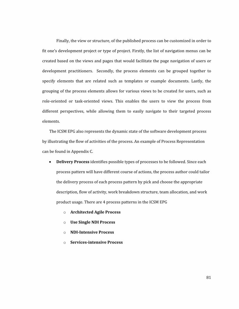
81
Finally, the view or structure, of the published process can be customized in order to
fit one’s development project or type of project. Firstly, the list of navigation menus can be
created based on the views and pages that would facilitate the page navigation of users or
development practitioners. Secondly, the process elements can be grouped together to
specify elements that are related such as templates or example documents. Lastly, the
grouping of the process elements allows for various views to be created for users, such as
role‐oriented or task‐oriented views. This enables the users to view the process from
different perspectives, while allowing them to easily navigate to their targeted process
elements.
The ICSM EPG also represents the dynamic state of the software development process
by illustrating the flow of activities of the process. An example of Process Representation
can be found in Appendix C.
• Delivery Process identifies possible types of processes to be followed. Since each
process pattern will have different course of actions, the process author could tailor
the delivery process of each process pattern by pick and choose the appropriate
description, flow of activity, work breakdown structure, team allocation, and work
product usage. There are 4 process patterns in the ICSM EPG
o Architected Agile Process
o Use Single NDI Process
o NDIIntensive Process
o Servicesintensive Process

82
Figure 38 illustrates how to configure the defined activities and tasks for each phase
and Figure 39 shows how to create the relationship between each activity or each task in
activity diagram representation.
Figure 38: Work Breakdown Structure for Architected Agile Process
Figure 39: Activity Diagram of an Explore Current System Activity

83
• Work Breakdown Structure represents the dynamic perspective of software
process by defining the software development phases and identifying a group of
tasks or activities for each phase. Moreover, by using UML activity diagram notation,
the process author can define the swim lane or scope of responsibilities for each
role and define the synchronization milestone, branching conditions, and
concurrent activities.
6.3. Discussion
6.3.1. Comparison Software Process Modeling Tools
Because of the complexity of the software process, various process definition languages
(PDL), process modeling tools (PML), workflow representation language, and Electronic
Process Guide generator tools have been created to represent and characterize software
processes and their related activities, roles, artifacts, and tools. [Fugetta 2000]. Main
purposes of software process modeling tools are to support and facilitate in process
understanding, process design, training and education, process simulation and
optimization, and process support. To model the LeanMBSE and ICSM, the EPG generator
tools have an advantage over PDLs since PDLs have limitations in representing non‐
sequential processes. PDLs require known pre‐condition, post‐condition, and sequence of
tasks. On the contrary, LeanMBASE and ICSM are risk‐driven process and the sequence of
tasks depends on the project risks.
IBM Rational Method Composer, Spearmint, and Little‐JIL are evaluated in order to
find the most appropriate tool to represent the process guidelines and to be experimented
in the software engineering class.

84
Spearmint vs. IBM Rational Method Composer
To compare between two EPG generator tools, Spearmint and IBM RMC, the criteria of
process modeling tools defined by [Humphrey 1989] are used as a foundation. The analysis
results are as followed:
• Representation of Process Elements – IBM RMC provides more representations for
guidance such as checklist, example, guidelines, template, and tool mentor.
Additionally, IBM RMC allows the process author to define skills for each role and
detailed steps for each task.
• Representation of Relationship Between the Process Elements – Spearmint
describes process elements textually, which IBM RMC is using graphical and textual
representation.
• Representation of a Process – Spearmint generates the behavior and functional
diagram for the process, while IBM RMC provides the process representation via
work breakdown structure (WBS) and activity diagram, which can be represented
hierarchically to show the tasks and sub tasks detail.
• Support Reusable of Content in the Process – IBM RMC separates method content
and process content, hence each process element are reusable. Also the method
content can be updated without affecting the process content.
• Dynamic Process Configuration – Both Spearmint and IBM RMC are not able to tailor
a process guideline in real‐time.
• Integration to the other Software Engineering Tools – IBM RMC are able to integrate
with various IBM tools and other tools such as Microsoft Project or Concurrent
Versions System (CVS).

85
• Comparative Usage feedback – Both Spearmint and IBM RMC are easy to use, but the
process author found that Spearmint is difficult to tailor or update the content.
LittleJIL vs. IBM Rational Method Composer
Little_JIL and IBM RMC are used to prototype the process guidelines for ICSM. This
section addresses the commonalities and differences of EPFC and Little‐JIL framework.
• Process lifecycle ‐ Both IBM RMC and Little‐JIL have basic ability to model the
software lifecycle as concurrent and iterative development lifecycle. However, there
is another challenge in order to model complete ICSM. Different risks can create
different ICSM processes. Hence, the process model needs ability to customize a
process guideline in real‐time based on the project risks. We call this ability as
“dynamic process configuration”. Currently, neither IBM RMC nor Little‐JIL provides
this capability.
• Process elements and their relationships ‐ IBM RMC provides more representations
for guidance such as checklist, example, guidelines, template, and tool mentor.
• Communication process ‐ Unlike the sophisticated and luxurious process elements
of IBM RMC, with the simple yet detailed tree‐like structure diagram, Little‐JIL can
precisely represent the software processes. With expandable step/sub‐step options,
the process performer can select to see the overview or detail information of the
project. With various kinds of notation for various kinds of step relationship and
little‐JIL formalism, we can effectively communicate the software process with very
precise information
• Facilitate process reuse ‐ Opposite to IBM RMC, for Little‐JIL, in order to represent
the preciseness and elaborateness of software process, it turns the process model to

86
be very project‐specific. Hence, this makes reuse of the model less frequent, but
enables the reuse to be checked for consistency
• Support process evolution ‐ When the project evolves and expands, Little‐JIL
supports the expandability in some extent. One can specify as many sub‐steps of
sub‐steps as needed. But if the project evolution causes the process structural
transformation, it will often cause tedious works to change the whole structure. So,
the process model can be expandable in vertical way but limited in horizontal way.
Because of the project‐specific preciseness, it is more difficult to tailor the process to
fit with projects in different scenario, but again more consistency‐checkable.
• Facilitate process management – IBM RMC and Little‐JIL support this criterion in
different ways. IBM RMC provides basic information to help the project manager
develop the project planning. Little‐JIL is stronger in supporting analysis of
consistency, completeness, and correctness, but has fewer constructs for assessing
required resources.
• Usability study ‐ To test the usability, preliminary experiment is conducted with
target users. The first group is graduate students who took software engineering
class, used paper‐based guidelines, familiar with software engineering process
especially LeanMBASE, and have brief knowledge about ICM. The second group is
first year graduate students who plan to take software engineering class, have never
used paper‐based guidelines, and have brief knowledge about software engineering
process and ICM. After briefing about ICM, we are observing both groups using ICM
process guidelines both in IBM RMC and Little‐JIL. During the study, project roles is
assigned to participants and asked them to find out their scope of responsibilities
from both tools. We found that, comparing with Little‐JIL, it is easier for the
87
participants to find role‐based tasks from ICSM‐EPG. After observation, post‐
interview is conducted. The open‐ended questions were asked during the
interview. The results show that the first group prefers ICSM‐EPG because it
provides a lot of information and link to external tools and document templates.
The second group prefers Little‐JIL because it is simple and easy to understand.
Both groups concur that ICSM‐EPG is very complex, difficult to get the overview
picture, and easy to get lost. On the other hand, both groups mentioned that Little‐
JIL does not represent responsibility in role‐based fashion, and it is very difficult to
find tasks that one has to do.
6.3.2. ICSM EPG Analysis
Fall 2008 is the first semester that Software Engineering students at USC have used the
EPG to guide their software development projects. In this section, I will provide analyses on
the data of students’ efforts spent on their projects and the results comparing the use of the
EPG and the use of the paper‐based guidelines. The EPG is evaluated based on process
model objectives defined by Humphrey and Kellner [Humphrey 1989] and good
characteristics of process modeling tools defined by Fuggetta [Fuggetta 2000].
Based on Humphrey and Kellner [Humphrey 1989]’s four objectives of a good software
modeling process tool, we found that
• In enabling effective communication regarding the process, RMC not only
provides basic process elements representation, such as roles, tasks, and artifacts or
additional representations such as checklist, tool mentor, and template, but it also
allows one to create special types of process elements with customized notations to
fit with one’s development projects. This benefit empowers the process engineers

88
with more alternatives to provide guidance and various types of supporting
materials.
• In facilitating process reuse, RMC clearly separates the method contents and
process contents, so the process engineer can tailor the method content without
affecting the process content, and vice versa. For example, when a process engineer
creates a new delivery process or an activity diagram, the current tasks and roles
can be reused as needed.
• In supporting process evolution, RMC fully supports process tailoring and
configurations, the EPG can surely be extended to support process evolution.
• In facilitating process management, RMC is fully interoperable with project
management tools such as the IBM Rational Team Concert [IBM RTC] and IBM
Rational Portfolio Manager [IBM RPM]. Although the current version of the EPG
does not provide project management facilities, it will be our challenge in the future
to pick the right tool to integrate with the software engineering class, as well as to fit
the nature of the development projects.
Secondly, to enable effective communication among various stakeholders, it is
important to use nomenclatures that will be widely comprehensible. RMC provides a rich
set of notations, such as process element icons and graphical representations in the delivery
process descriptions and activity diagrams. Based on the criteria of good notations
proposed by Humphrey [Humphrey 1989], we evaluated notations provided in RMC and
found that
• In preciseness and conciseness, RMC provides a set of graphical representations
that sharply conveys the meaning of each process element.

89
• In convenience of use, RMC provides sets of functionalities allowing the process
engineers to easily pick and choose the notations and elements in the course of
modeling a process.
• In being commonly understood, RMC uses pictorial icons that represent standard
real‐world objects. The users will be able to interpret the icons in universal
meanings
• In being suitable for representing a broad range of software functions, even though
the current sets of notations cover a wide range of software activities, RMC allows
the addition of extra custom process element icons to fit with any additional
requirements a process engineer might see fit.
Lastly, Heidrich proposed in [Heidrich et.al. 2006] that people‐oriented process
information should describe role‐specific responsibilities, activities, and abilities. RMC
represents this information by using work products, tasks, and properties respectively. The
groupings of these elements allow the process engineers to illustrate various perspectives
of the process to the readers, enabling the ability to represent the big picture of the process,
as well as specific views.
6.3.3. Effort Comparison between EPG and nonEPG
To determine the effectiveness of using the ICSM EPG, it is compared with the use of
traditional paper‐based versions of the guidelines. The data used to perform the
comparisons were the effort, or the number of hours, spent by students in performing
specific project‐related activities. These data were taken from the USC’s CSCI577a Software
Engineering course of fall 2007 to 2008 semesters, where the fall 2007 semester utilized the
paper‐based version and the fall 2008 semester utilized the electronic version. To
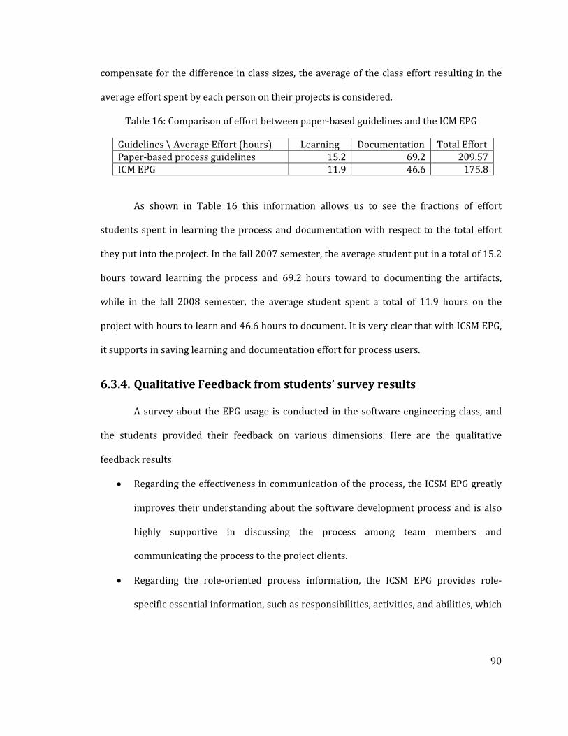
90
compensate for the difference in class sizes, the average of the class effort resulting in the
average effort spent by each person on their projects is considered.
Table 16: Comparison of effort between paper‐based guidelines and the ICM EPG
Guidelines \ Average Effort (hours) Learning Documentation Total EffortPaper‐based process guidelines 15.2 69.2 209.57 ICM EPG 11.9 46.6 175.8
As shown in Table 16 this information allows us to see the fractions of effort
students spent in learning the process and documentation with respect to the total effort
they put into the project. In the fall 2007 semester, the average student put in a total of 15.2
hours toward learning the process and 69.2 hours toward to documenting the artifacts,
while in the fall 2008 semester, the average student spent a total of 11.9 hours on the
project with hours to learn and 46.6 hours to document. It is very clear that with ICSM EPG,
it supports in saving learning and documentation effort for process users.
6.3.4. Qualitative Feedback from students’ survey results
A survey about the EPG usage is conducted in the software engineering class, and
the students provided their feedback on various dimensions. Here are the qualitative
feedback results
• Regarding the effectiveness in communication of the process, the ICSM EPG greatly
improves their understanding about the software development process and is also
highly supportive in discussing the process among team members and
communicating the process to the project clients.
• Regarding the role‐oriented process information, the ICSM EPG provides role‐
specific essential information, such as responsibilities, activities, and abilities, which

91
crucially help the student teams in task allocation, project planning, and project
management.
• Regarding the process modeling and support, the ICSM EPG highly assists the
students’ teams to plan and execute the process.
Moreover, the ICSM EPG mentors the students on the list of artifacts to be created,
maintained, and delivered. The majority of the students nominated the interactive graphical
representation as the most useful feature, while the improper search function was the least
useful function. Role‐specific information, delivery process, templates, and example
documents were the features that were most helpful in aiding them in learning and
understanding the development process.
6.3.5. Quantitative Survey Results on ICSM EPG
Table 17 provides a summary result of the quantitative survey from the students
who use the ICSM EPG. Based on a score of 5, the process users agree that the ICSM EPG
supports them in all categories. In the first category, the process users concur that the ICSM
EPG improves their understanding about the software development process, enables the
communication about software development process among team members, and enables
the communication about the software development process with the client. In the second
category, the process users highly agree that the ICSM EPG provides role‐specific
information about the software development process, helps one to understand
responsibilities of each role with respect to the process, assign tasks to each role if they
were the project manager, select the role that one wants, and explain activities in which
each has to participate. In the process modeling and support category, the process users
agree that the ICSM EPG provides essential information for one to plan and execute one’s

92
software development process, provides information that supports them in process
adaptation to fit with project status, and provides information about the software
development process and its deliverables in each phase. In the last category, the process
users agree that the ICSM EPG helps one to eliminate inconsistencies in the process
specification, easy to user, easy to understand and has a high clarity of navigation.
Moreover, more than 75% of process users prefer the electronic version of the process
guidelines. On the other hand, 25% of process users would prefer to have both electronic
version and paper‐based version to read off‐line. Detailed results of the quantitative survey
can be found in Appendix L.
Table 17: Results of ICSM EPG Survey
Category Result (Scale of 5) I. Effective communication regarding the process 3.86 II. Support People‐oriented process information 4.14 III. Support Process modeling 3.97 IV. Support Process Improvement 3.76
6.3.6. Quantitative Survey Results regarding PDFguideline vs EPG
Another survey is conducted to compare the experience on using PDF‐guidelines
and the EPG. The target groups are the students who took Software Engineering course
during fall 2005 – 2007 where the LeanMBASE process guidelines was available only in PDF
format. The questions are asked to evaluate the PDF‐guidelines usage experience. Table 18
summarizes the results of the survey in each category. The PDF‐guidelines moderately
supports the process users in learning about the process, provides people‐oriented process
information, and supports process modeling, but fairly support process improvement.

93
Table 18: Results of PDFguidelines Survey
Category Result (Scale of 5) I. Effective communication regarding the process 3.44 II. Support People‐oriented process information 3.30 III. Support Process modeling 3.18 IV. Support Process Improvement 2.69
Comparing the evaluation result between Table 17 for ICSM EPG evaluation and
Table 18 PDF‐guideline evaluation, it is clearly shown that the process users prefer the
ICSM EPG in every category.
Furthermore, the target groups are introduced about the ICSM EPG and are asked to
compare between the ICSM EPG and PDF‐guidelines in each category. To test whether the
ICSM EPG outperform the PDF guidelines, the target groups are asked whether they agree
that the EPG is superior to the PDF‐guidelines in each category. Table 19 shows that the
target groups strongly agree that the EPG is better than the PDF‐guidelines in every aspect.
Detailed information and questions can be found in Appendix M.
Table 19: Comparison between the EPG and PDFGuidelines
Category (1 = Totally Disagree , 5 = Totally Agree)
Result
I. The EPG is more effective in process communication 4.11II. The EPG provides better support in people‐oriented process information 4.40III. The EPG provides better support in process modeling 4.19 IV. The EPG provides better support in process Improvement 4.29
6.3.7. Conclusions
Both quantitative and qualitative feedback has confirmed that the electronic process
guide supports the process users in process learning, team communicating, project
managing, task scheduling, and process improving. It also saves the effort spent in learning

94
about a new process. Hence, it is clearly shown that the ICSM EPG teams outperformed the
teams that used PDF‐process guidelines.

95
Chapter 7 : Conclusion and Future Work
7.1. General Conclusions
As technology evolves, various ready‐made software components can be used to speed
up the software development, especially for rapid‐fielding projects, where time‐to‐market is
the key factor to gain advantage over the competition. Current software development
process models and process guidelines are either outdated or not supported by the updated
technology, especially for Services‐intensive projects. Based on the Incremental
Commitment Spiral Model, there are 4 process patterns that dominate our Software
Engineering class rapid‐fielding projects, which are Architected Agile, Use Single NDI, NDI‐
Intensive, and Services‐intensive process patterns. The experiments have been done to
confirm that the Incremental Commitment Spiral Model and its process guidelines support
the team in developing rapid‐fielding software project. However, it is important to note that
the results are currently only representative of small web services applications.
7.2. Summary of Contributions
In summary, this dissertation describes how the Incremental Commitment Spiral
Model can be applied to four process patterns of the rapid‐fielding projects. To provide the
process guidelines, the related software development process guidelines, or standards, are
investigated and analyzed. The details of four ICSM rapid‐fielding process guidelines are
developed based on various good practices and the process content is published by using
the IBM Rational Method Composer. Additionally, the process decision drivers, which help
the development team in selecting the appropriate process pattern, are developed. The data
96
are collected from 5 years of Software Engineering courses (2005‐2009) and are analyzed
to validate the hypotheses.
7.3. Future Work
Several suggested future research directions include:
• Experiment on Agile Development – although Agile Development would be a good
process pattern choice for rapid‐fielding projects, it is very difficult to run an
experiment for agile development in the classroom environment. Additionally, agile
development requires agile‐ready personnel, which is lack in most of the software
engineering students in this class. Hence, it would be great to develop process
guidelines, including process decision drivers to cover agile development.
• Replicate Experiment in Industry Environment – although the projects
developed in the software engineering class environment are comparable to
projects developed in the industry environment, to proof that the process guidelines
are applicable to all rapid‐fielding projects especially large‐scale rapid‐fielding
project, the experiment should be repeated in the industry environment.
• Extend COCOTS to support servicesbased estimation – COCOTS can be used to
provide cost estimation for NDI‐intensive projects. However, it would be beneficial
to extend COCOTS to support services‐intensive project cost estimation.
97
References
[Agile 2009] Agile, Principles behind the agile manifesto, http://agilemanifesto.org/principles.html. accessed on 8/4/2009.
[Amazon ] Amazon Payment Services, https://payments.amazon.com/sdui/sdui/index.htm
[ Ambler, 2009] Ambler, S.W., Agile Unified Process, http://www.ambysoft.com/unifiedprocess/agileUP.html Accessed 8/4/2009
[Basili 2001] Basili, V., Boehm, B., "COTS‐Based Systems Top 10 List," Computer, Volume 34, Number 5, May, 2001, pp. 91‐93
[Becker 1999] Becker, U., Hamann, D., and , “Support for the Process Engineer: The Spearmint Approach to Software Process Definition and Process Guidance”. Matthias Jarke, Andreas Oberweis(Eds.): Advanced Information Systems Engineering, Proceedings of the 11th International Conference CAiSE'99, Lecture Notes in Computer Science, Vol. 1626, pp. 119‐133. Springer, 1999
[Bhuta 2007] Bhuta, J., “A Framework for Intelligent Assessment and Resolution of Commercial‐Off‐The‐Shelf Product Incompatibilities” PhD Dissertation, Department of Computer Science, University of Southern California, August 2007
[Boehm 1988] Boehm B, "A Spiral Model of Software Development and Enhancement", IEEE Computer, 21(5):61‐72, May 1988
[Boehm 1996] Boehm B, Anchoring the Software Process, IEEE Software, v.13 n.4, p.73‐82, July 1996
[Boehm 2004] Boehm, B. and Turner, R. 2004. Balancing agility and discipline: a guide for the perplexed. Addison‐Wesley, Boston.
[Boehm 2007a] Boehm, B. and Lane, J., “Using the Incremental Commitment Model to Integrate Systems Acquisition, Systems Engineering, and Software Engineering,” “Cross Talk, October 2007, pp.4‐9
[Boehm 2007b] Boehm, B., “Agility and quality.” IBM Agile Conference, May 15, 2007; ICSE Work‐shop on Software Quality, May 21, 2007.
[Boehm 2008] Boehm, B. and Bhuta, J., "Balancing Opportunities and Risks in Component‐Based Software Development," IEEE Software, November‐December 2008, Volume 15, Issue 6, pp. 56‐63

98
[Boehm 2009a] Boehm, B. and Lane, J., "Guide for Using the Incremental Commitment Model (ICSM) for Systems Engineering of DoD Projects" USC CSSE Tech Report 2009‐500
[Boehm 2009b] Boehm, B., Lane, J. and Koolmanojwong, S. "A Risk‐Driven Process Decision Table to Guide System Development Rigor," Proceedings of the 19 th International Conference on Software Engineering, Singapore, July, 2009.
[Cass 2000] Cass, A.G., Lerner, B.S., McCall, E.K., et al., Little‐JIL/Juliette: A Process Definition Language and Interpreter. Int. Conf. on Software Engineering, Ireland, (2000) 754‐758.
[CMMI‐COTS] CMMI for COTS‐based Systems, http://www.sei.cmu.edu/publications/documents/03.reports/03tr022.html
[CMMI‐Services] CMMI for Services Version1.2, ftp://ftp.sei.cmu.edu/pub/documents/09.reports/09tr001.doc
[CMMI 2009] CMMI for Services flyer, www.sei.cmu.edu/cmmi/models/CMMI‐for‐Services‐one‐pager‐20090320.doc
[CrossTalk] CrossTalk, The Journal of Defense Software Engineering, http://www.stsc.hill.af.mil/index.html, accessed 08/24/09
[Dymond 2010] Dymond R. , The Lean Agile Executive Blog, A Scrum project that failed. http://www.innovel.net/?p=62, accessed on 10/14/2010
[FAR] Federal Acquisition Regulation – Term definitions https://www.acquisition.gov/far/html/Subpart%202_1.html
[Fuggetta 2000] Fuggetta, A., Software process: a roadmap, Proceedings of the Conference on The Future of Software Engineering, p.25‐34, June 04‐11, 2000
[Google Map] Google Map, http://maps.google.com/
[Haumer 2005] Haumer, P. IBM Rational Method Composer: Part 1: Key concepts, December 2005, http://www.ibm.com/developerworks/rational/library/dec05/haumer/
[Heidrich 2006] Heidrich, J., Münch, J., Riddle, W.E., Rombach, D.: People‐oriented Capture, Display, and Use of Process Information. In: Acuña, S.T., Sánchez‐Segura, M.I. (eds.) New Trends in Software Process Modeling. Series on Software Engineering and Knowledge Engineering, vol. 18, pp. 121–179. World Scientific Publishing Company, Singapore
[Humphrey 1989] Humphrey, W. and Kellner, M. “Software Process Modeling: Principles of Entity Process Models.” Proceedings of the 11th International Conference on Software Engineering, PA, USA, 1989. pp. 331 – 342.

99
[IBM RMC] IBM Rational Method Composer http://www‐01.ibm.com/software/awdtools/rmc/
[IBM RPM] IBM Rational Portfolio Manager http://www‐01.ibm.com/software/awdtools/portfolio/
[IBM RTC] IBM Rational Team Concert http://www‐01.ibm.com/software/awdtools/rtc/
[ICSM EPG] Instructional ICSM‐Software Electronic Process Guide, http://greenbay.usc.edu/IICSMSw/index.htm
[Koolmanojwong 2007] Koolmanojwong, S., et.al, "Comparative Experiences with Software Process Modeling Tools for the Incremental Commitment Model" USC CSSE Technical Report 2007‐824
[Koolmanojwong 2008] Koolmanojwong, S., et.al, "Incremental Commitment Model Process Guidelines for Software Engineering Class", USC CSSE Technical Report 2008‐832
[Koolmanojwong 2009] Koolmanojwong, S. and Boehm, B., "Using Software Project Courses to Integrate Education and Research: An Experience Report," Proceedings of the 2009 22nd Conference on Software Engineering Education and Training ‐ Volume 00, CSEET, pp. 26‐33
[Koolmanojwong 2010] Koolmanojwong, S. and Boehm, B., "The Incremental Commitment Model Process Patterns for Rapid‐Fielding Projects," ICSP 2010, Paderborn, Germany
[Lenth 2001] Lenth, R. V., “Some practical guidelines for effective sample size determination”, American Statistician, 2001, 55, 187‐193.
[Li 2006] Li, J., et al., “An empirical study of variations in COTS‐Based Software Development Processes in Norwegian IT industry,” Journal of Empirical Software Engineering vol. 11, no.3, 2006, pp 433‐461
[Morisio 2000] Morisio, M., C. B. Seaman , A. T. Parra , V. R. Basili , S. E. Kraft , S. E. Condon, Investigating and improving a COTS‐based software development, Proceedings of the 22nd international conference on Software engineering, p.32‐41, June 04‐11, 2000, Limerick, Ireland
[Ning] Ning, http://www.ning.com/, accessed 08/24/08
[Oppenheim 2010] Oppenheim B. W., Murman E.M., and Secor D.A., “Lean Enablers for System Engineering”, doi: 10.1002/sys.20161
[Pew 2007] Pew, R. W., and Mavor, A. S. , “Human‐System Integration in the System Development Process: A New Look”. 2007, National Academy Press.
[Poppendieck 2003] Poppendieck, M and Poppendieck, T. (2003); Lean software development, an agile toolkit. Addison Wesley.

100
[Phongpaibul et.al 2007] Phongpaibul, M., Koolmanojwong, S., Lam, A., and Boehm, B. "Comparative Experiences with Electronic Process Guide Generator Tools," ICSP 2007, pp. 61‐72
[ProgrammableWeb] ProgrammableWeb http://www.programmableweb.com/mashups accessed on 11/9/2009
[Rising 2000] Rising, L., & Janoff, N. The Scrum Software Development Process for Small Teams. IEEE Software, July/August 2000
[Scaffidi 2009] Scaffidi, C.,” Topes: Enabling End‐User Programmers to Validate and Reformat Data”, PhD Dissertation, Technical Report CMU‐ISR‐09‐105, Institute for Software Research (ISR), Carnegie Mellon University, May 2009.
[Smith 2004] Smith, J. “An Alternative to Technology Readiness Levels for Non‐Developmental Item (NDI) Software”, CMU‐SEI Technical Report, April 2004
[USC CSCI577] USC – CSCI577 Software Engineering Class I Website, http://greenbay.usc.edu/csci577/fall2008/site/index.html accessed on 08/24/08
[VModel 2009] V‐Model Lifecycle Process Model http://www.v‐modell.iabg.de/kurzb/vm/k_vm_e.doc accessed on 10/9/2009
[Yahoo] Yahoo Developer Network, http://developer.yahoo.com/
[Yang 2006] Yang, Y., "Composable Risk‐Driven Processes for Developing Software Systems from Commercial‐Off‐The‐Shelf (COTS) Products," PhD Dissertation, Department of Computer Science, University of Southern California, December 2006
[Yang 2007] Yang Y. and Boehm B., COTS‐Based Development Process guidelines, http://greenbay.usc.edu/csci577/spring2007/site/guidelines/CBA‐AssessmentIntensive.pdf Accessed 08/24/07

101
Appendix A : Characteristics of each ICSM Process Pattern
Table 20: Characteristics of each ICSM Process Pattern
Special Case Example
Size,
Complexity
Change
Rate
(%/M
onth)
Criticality
NDI
Support
Organizati
onal and
Personnel
Capability
Time/Buil
d;
Time/Incre
ment
1. Use NDI Small accounting
Complete
2. Agile E‐services Low 1‐30 Low‐Med Good; in place
Agile‐ready Med‐high
<= 1 day;
2‐6 weeks
3. Architected Agile
Business data processing
Med 1‐10 Med‐High Good; most in place
Agile‐ready Med‐high
2‐4 weeks;
2‐6 months
4. Formal Methods
Security kernel; Safety‐critical LSI chip
Low 0.3 Extra High None Strong formal methods experience
1‐5 days;
1‐4 weeks
5. HW with embedded SW component
Multi‐sensor control device
Low 0.3‐1 Med‐Very High
Good; in place
Experienced; med‐high
SW: 1‐5 days;
Market‐driven
6. Indivisible IOC Complete vehicle platform
Med‐High
0.3‐1 High‐ Very High
Some in place Experienced; med‐high
SW: 2‐6 weeks;
Platform: 6‐18 months
7. NDI‐ intensive Supply chain management
Med‐High
0.3‐3 Med‐Very High
NDI‐driven architecture
NDI‐ experienced; med‐high
SW: 1‐4 weeks;
Systems: 6‐18 months
8. Hybrid agile/ plan‐driven system
C4ISR system Med‐Very High
Mixed parts; 1‐10
Mixed parts; Med‐Very High
Mixed parts Mixed parts 1‐2 months;
9‐18 months
9. Multi‐owner system of systems
Net‐centric military operations
Very High
Mixed parts; 1‐10
Very High Many NDIs; some in place
Related experience, med‐high
2‐4 months;
18‐24 months
10. Family of systems
Medical device product line
Med‐Very High
1‐3 Med‐Very High
Some in place Related experience, med‐high
1‐2 months;
9‐18 months

102
Table 20: Continued
11. Brownfield Incremental legacy phaseout
High‐Very High
0.3‐3 Med‐High NDI as legacy replacement
Legacy re‐engineering
2‐6 weeks/ refactor ;
2‐6 months
12a. Net‐ Centric Services— Community Support
Community Services or Special Interest Group
Low‐Med
0.3‐3 Low‐Med Tailorable service elements
NDI‐ experienced
<= 1 day;
6‐12 months
12b. Net‐Centric Services—Quick Response Decision Support
Response to competitor initiative
Med‐High
3‐30 Med‐High Tailorable service elements
NDI‐ experienced
<= 1 day ;
QR‐driven
Legend:
C4ISR: Command, Control, Computing, Communications, Intelligence, Surveillance, Reconnaissance; HW: Hardware; IOC: Initial Operational Capability; NDI: Non‐Development Item; QR : Quick Response ; SW: Software.

103
Appendix B : Key Activities for Each Process Pattern of the ICSM
Table 21: Key Activities for each process pattern
Special Case Example Key Stage I Activities: Incremental
Definition Key Stage II Activities: Incremental
Development, Operations
1. Use NDI Small accounting Acquire NDI Use NDI
2. Agile E‐services Skip Valuation, Architecting phases Scrum plus agile methods of choice
3. Architected Agile
Business data processing
Combination Valuation, Architecting phases. Complete NDI preparation
Architecture‐based Scrum of Scrums
4. Formal Methods
Security kernel; Safety‐critical LSI chip
Precise formal specification Formally‐based programming language; formal verification
5. HW with embedded SW component
Multi‐sensor control device
Concurrent HW/SW engineering. CDR‐level ICM DCR
IOC Development, LRIP, FRP. Concurrent version N+1 engineering
6. Indivisible IOC Complete vehicle platform
Determine minimum‐IOC likely, conservative cost. Add deferrable SW features as risk reserve
Drop deferrable features to meet conservative cost. Strong award fee for features not dropped
7. NDI‐ intensive Supply chain management
Thorough NDI‐suite life cycle cost‐benefit analysis, selection, concurrent requirements/ architecture definition
Pro‐active NDI evolution influencing, NDI upgrade synchronization
8. Hybrid agile/ plan‐driven system
C4ISR system Full ICM; encapsulated agile in high change, low‐medium criticality parts (Often HMI, external interfaces)
Full ICM, three‐team incremental development, concurrent V&V, next‐increment rebaselining
9. Multi‐owner system of systems
Net‐centric military operations
Full ICM; extensive multi‐owner team building, negotiation
Full ICM; large ongoing system/software engineering effort
10. Family of systems
Medical device product line
Full ICM; Full stakeholder participation in product line scoping. Strong business case
Full ICM. Extra resources for first system, version control, multi‐stakeholder support
11. Brownfield Incremental legacy phaseout
Re‐engineer/refactor legacy into services Incremental legacy phaseout
12a. Net‐Centric Services— Community Support
Community Services or Special Interest Group
Filter, select, compose, tailor NDI Evolve tailoring to meet community needs
12b. Net‐Centric Services—Quick Response Decision Suppport
Response to competitor initiative
Filer, select, compose, tailor NDI Satisfy quick response; evolve or phase out
Legend: C4ISR: Command, Control, Computing, Communications, Intelligence, Surveillance, Reconnaissance; CDR: Critical Design Review; DCR: Development Commitment Review; FRP: Full‐Rate Production ; HMI: Human‐Machine Interface ; HW: Hardware; IOC: Initial Operational Capability; LRIP: Low‐Rate Initial Production; NDI: Non‐Development Item; SW: Software; V&V: Verification and Validation.

104
Appendix C : CSCI 577 projects
Table 22: List of Projects and their processes in Fall 2005
2005 # Project Name Process Followed
P1 Open Source Discussion Board and Research Platform ‐ I
LeanMBASE
P2 Physics Education Research (PER) LeanMBASE P3 Pasadena High School Computer Network Study COTS‐Based DevelopmentP4 Virtual Football Trainer System COTS‐Based DevelopmentP5 Data Mining PubMed Results LeanMBASE P6 USC Football Recruiting Database LeanMBASE P7 USC Equipment Inventory Database LeanMBASE P8 Data Mining of Digital Library Usage Data LeanMBASE
P9 J2EE‐based Session Management Framework Extension
LeanMBASE
P10 Code Generator – Template based LeanMBASE P11 dotProject and Mantis integration LeanMBASE
P12 Mule as a highly scalable distributed framework for data migration
COTS‐Based Development
P13 Develop a Web Based XML Editing Tool LeanMBASE P14 CodeCount™ Product Line with XML and C++ ‐ IP15 COSYSMO Extension to COINCOMO LeanMBASE P16 Intelligent, 'diff'ing CodeCount Superstructure LeanMBASE P19 EBay Notification System LeanMBASE P21 Rule‐based Editor LeanMBASE P22 Open Source Discussion Board and Research
Platform ‐ II LeanMBASE
P23 CodeCount™ Product Line with XML and C++‐ II LeanMBASE
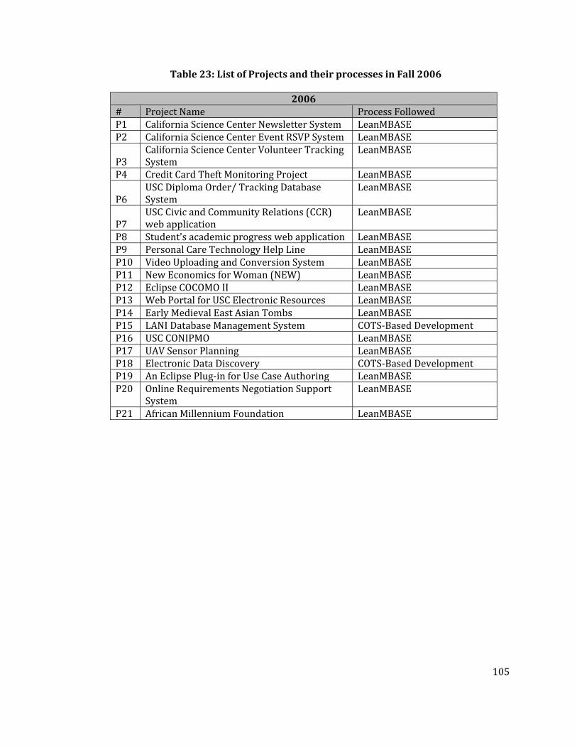
105
Table 23: List of Projects and their processes in Fall 2006
2006 # Project Name Process Followed P1 California Science Center Newsletter System LeanMBASE P2 California Science Center Event RSVP System LeanMBASE
P3 California Science Center Volunteer Tracking System
LeanMBASE
P4 Credit Card Theft Monitoring Project LeanMBASE
P6 USC Diploma Order/ Tracking Database System
LeanMBASE
P7 USC Civic and Community Relations (CCR) web application
LeanMBASE
P8 Student's academic progress web application LeanMBASE P9 Personal Care Technology Help Line LeanMBASE P10 Video Uploading and Conversion System LeanMBASE P11 New Economics for Woman (NEW) LeanMBASE P12 Eclipse COCOMO II LeanMBASE P13 Web Portal for USC Electronic Resources LeanMBASE P14 Early Medieval East Asian Tombs LeanMBASE P15 LANI Database Management System COTS‐Based DevelopmentP16 USC CONIPMO LeanMBASE P17 UAV Sensor Planning LeanMBASE P18 Electronic Data Discovery COTS‐Based DevelopmentP19 An Eclipse Plug‐in for Use Case Authoring LeanMBASE P20 Online Requirements Negotiation Support
System LeanMBASE
P21 African Millennium Foundation LeanMBASE

106
Table 24: List of Projects and their processes in Fall 2007
2007 # Project Name Process Followed P1 Box Office Database System LeanMBASE P2 Online Peer Review System LeanMBASE P3 Thai CDC Software Tool LeanMBASE P4 USC COINCOMO LeanMBASE P5 Crystal Stairs Dashboard LeanMBASE P6 Family & Homeless Well‐Being Project LeanMBASE P7 BTI Appraisal Projects LeanMBASE P8 LAMAS Customer Service Application LeanMBASE P9 Web‐based service for TPC Foundation LeanMBASE P10 REEO Database LeanMBASE P11 BID review System LeanMBASE P12 THSA Website Project LeanMBASE P13 EEO Section Database LeanMBASE P14 Conference Room Reservation System LeanMBASE P15 Proctor and Test Site Tracking System LeanMBASE P16 E‐Mentoring program LeanMBASE P17 Social Networking Tools for Librarians LeanMBASE P18 EZSIM II LeanMBASE P19 Los Angeles County Generation Web
Initiative LeanMBASE
P20 Development of hunter‐gatherer database LeanMBASE

107
Table 25: List of Projects and their processes in Fall 2008
2008 # Project Name Process Followed P1 Master Pattern Architected Agile P2 Housing Application Tracking System Architected Agile P3 Revamping Proyecto Pastoral Architected Agile P4 UNO Web Tool Architected Agile P5 Hunter‐gatherer interactive research database Architected Agile P6 The IGM On‐Line Art Gallery** COTS‐Based Development P7 EZBay Architected Agile P8 AAA Petal Pushers Remote R&D Architected Agile P9 Information Organization System** COTS‐Based Development P10 The Roots of Inspiration web site** Architected Agile P11 Web‐based Service for TPC Foundation COTS‐Based Development P12 Online Peer Review System for Writing Program Architected Agile P13 Acme Research Engine for USC‐WB Archives Architected Agile
P14 The Virtual Assistant Living and Education Program
Architected Agile
P15 Data Base for III, Inc. COTS‐Based Development P16 Theatre Script Online Database Architected Agile
** denotes the disregarded teams due to unusual circumstance of the projects, which could the outlier in data collection
Table 26: List of Projects and their processes in Fall 2009
2009 # Project Name Process Followed P1 Online DB support for CSCI 511 Architected Agile P2 SHIELDS for Family Architected Agile P3 Theater Stage Manager Program Architected Agile P4 Growing Great Online NDI‐Intensive P5 SPC Website Automation Enhancement NDI‐Intensive P6 VALE Information Management System Services‐Intensive P7 LANI D‐Base Architected Agile P8 Freehelplist.org Architected Agile P9 Early Medieval East Asian Timeline Architected Agile P10 BHCC Website Development Architected Agile P11 AI Client Case Management Database Architected Agile P12 AI Website Development Services‐Intensive P13 Healthcare The Rightway** NDI‐Intensive P14 AROHE Web Development Architected Agile
** denotes the disregarded teams due to unusual circumstance of the projects, which could the outlier in data collection

108
Appendix D : Projects that deliver in onesemester
Table 27: List of onesemester projects
Year Projects Group I – Prepare to transition within 12 weeks or recommend an NDI/NCS as a final deliverable 2005 Pasadena High School Computer Network Study2005 Virtual Football Trainer System2005 Mule as a highly scalable distributed framework for data migration2006 LANI Database Management System2006 Electronic Data Discovery2007 Thai CDC Software Tool2007 REEO Database2008 The IGM On‐Line Art Gallery2008 Information Organization System2008 Data Base for III, Inc.2009 Healthcare The Rightway Group II – Enter Operation Phase within 12 weeks2007 Box Office Database System2007 Family & Homeless Well‐Being Project2007 Social Networking Tools for Librarians2008 The Roots of Inspiration web site2008 Web‐based Service for TPC Foundation2009 SPC Website Automation Enhancement2009 VALE Information Management System2009 AI Website Development

109
Appendix E : Student General Information Questionnaire
Figure 40: Student Background Information Survey Page 1

110
Figure 41: Student Background Information Survey Page 2

111
Figure 42: Student Background Information Survey Page 3

112
Figure 43: Student Background Information Survey Page 4

113
Appendix F : Effort Category
Table 28: Effort Categories in Effort Reporting System
Operational Concept Development Implementation Analyze Current System Explore and evaluate alternatives Identify Shared Vision Analyze and prioritize capabilities to prototype Establish New Operational Concept Acquire NDI/ServicesIdentify System Transformation Prepare development / operational environment Identify Organizational and Operational Transformation Develop prototype Identify Objectives, Contraints and Priorities Develop componentAssess Operational Concept Assess Prototype / componentDocumenting of OCD Tailor NDI/ ServicesSystem and Software Requirements Development Integrate ComponentsSet up WinWin negotiation context Transition the systemNegotiate (during meeting) Develop Transition PlanNegotiation using WikiWinWin tool (after meeting) Develop Support PlanIdentify win conditions Provide TrainingIdentify issues Develop User ManualNegotiate options Documenting of PrototypingDevelop Requirements Definition Testing Assess requirements definition Identify Test CasesDocumenting of SSRD Identify Test PlanDocumenting of WinWin Negotiation Report Identify Test ProceduresSystem and Software Architecture Development Record Test ResultsAnalyze the Proposed System Identify Regression Test PackageDefine Technology‐Independent Architecture Documenting Test‐related documents Define Technology‐Dependent Architecture Perform custom component testSpecify Architecture Styles, Patterns and Frameworks Perform NDI/service component test Assess System Architecture perforn Integration testDocumenting of SSAD perform acceptance test
Life Cycle Planning perform regression test Identify Milestones and Products perform unit testIdentify Responsibilities and Skills Project Administration (currently not in ICSM EPG) Identify Life Cycle Management Approach Create and maintain project website Estimate Project Effort and Schedule using COCOMO II Interact with ClientsEstimate Project Effort and Schedule using COCOTS Interact between team membersAssess Life Cycle Content Learn about Incremental Commitment Model Detail Project Plan Learn about Application domainRecord Project Progress Prepare transition siteRecord Project Individual Effort Manage Code configurationIdentify Development Iteration Attend ARBAssess Development Iteration Planning and controlPerform Core Capabilities Drive‐Through Control Project PerformanceDocumenting of LCP Quality Management Documenting Iteration‐related cocuments Gather DefinitionsTrack problem and report closure Construct Traceability MatrixFeasibility Evidence Description Identify Configuration Management Strategy Analyze Business Case Identify Quality Management Strategy Identify, assess, and manage risks Verify and Validate Work Products Provide Architecture Feasibility Evidence Assess Quality Management Strategy Provide Process Feasibility Evidence Documenting of QMPAssess Feasibility Evidence Documenting of SIDAssess/Evaluate NDI/Services Candidate Documenting of review‐related document Check components Interoperability Documenting of FED

114
Appendix G : ICSM EPG: Roles, Activities, Work products, and Delivery
Process
Figure 44: Welcome Page of ICSM EPG

115
Figure 45: List of Roles in ICSM EPG
Figure 46: List of Practices in ICSM EPG

116
Figure 47: Practice Page in ICSM EPG

117
Figure 48: A task page in ICSM EPG
Figure 49: A role and responsibilities page in ICSM EPG

118
Figure 50: A delivery process page in ICSM EPG
Figure 51: list of work products in ICSM EPG

119
Appendix H : Example of Decision driver
Figure 52: Architected Agile Process Pattern Template

120
Figure 53: Use Single NDI Process Pattern Template
Figure 54: NDIIntensive Process Pattern Template

121
Figure 55: ServicesIntensive Process Pattern Template
Figure 56: An Architected Agile team with Architected Agile Decision Pattern

122
Figure 57: An Architected Agile team with Use Single NDI Decision Pattern
Figure 58: An Architected Agile team with NDIIntensive Decision Pattern
Figure 59: An Architected Agile team with ServicesIntensive Decision Pattern

123
Figure 60: An NDIintensive team with NDIIntensive Decision Pattern
Figure 61: An NDIintensive team with Architected Agile Decision Pattern

124
Figure 62: An NDIintensive team with Use Single NDI Decision Pattern
Figure 63: An NDIintensive team with ServicesIntensive Decision Pattern

125
Appendix I : Client Feedback Form – CSCI 577a
Project Name: __________________________________________ Team # _______ Please provide a ranking where indicated. Use a 1 5 scale where 1 is low and 5 is high. Where comments are requested, please include any descriptive statements you wish to add. FOR THE FIRST TWO ITEMS, consult your team's Development Commitment Package documentation by clicking on the project name in the table shown on the course webpage http://greenbay.usc.edu/csci577/fall2008/site/projects/index.html 1. Operational Concept Description (especially Sections: 2. Shared Vision; 3. System Transformation). How well did the team capture your ideas of what the new system should do? Ranking: (1‐5) Comments: 2. Team helpfulness Did the team suggest new idea about your project? Did the team support you in any project complexity? Ranking : (1‐5) Comments: FOR THE NEXT ITEMS, base your responses on your interactions with the project team and their product. 3. Team Responsiveness: Was the team responsive to you and to your requirements? Did the team answer any questions you might have had? How successful was the requirements negotiation between you and your team? Ranking : (1‐5) Comment: 4. Project Results: How satisfied are you with the prototype? How well does the proposed system meet the need identified by your project? Ranking: (1‐5) Comment: 5. Project Future: Do you think this project should be carried forward for development in CS577b? Has the team adequately identified and managed the potential risks and complications associated with the project? Do you foresee difficulties in transitioning this project into the development and implementation phase? Ranking : (1‐5) Comment: 6. Team Communication: How effective was the team in communicating with you? Do you feel you had enough meetings with them? Did the team make effective use of your time and expertise? What means did you use to communicate? Ranking : (1‐5) Comment: 7. Tools: Regarding software tools students used in the class 7a. Did the team share WinWin negotiation results with you? If so, how? Comment 7b. Did the team mention or describe any other software engineering tools? Comment: 8. Your Learning: Did you gain a better understanding of software engineering and information technology by participating in this project? Please provide specifics where possible. Ranking : (1‐5) Comment: 9. Suggestions about the course processes from your (a client's) perspective. Comment:

126
10. Overall Value: Did you feel your participation was worthwhile? Would you participate again? Did you find participation valuable as either a teaching or research activity? Ranking : (1‐5) Comment: If you have any other comments that you would like to offer, please feel free. We may get back to you in the future on these for clarification.
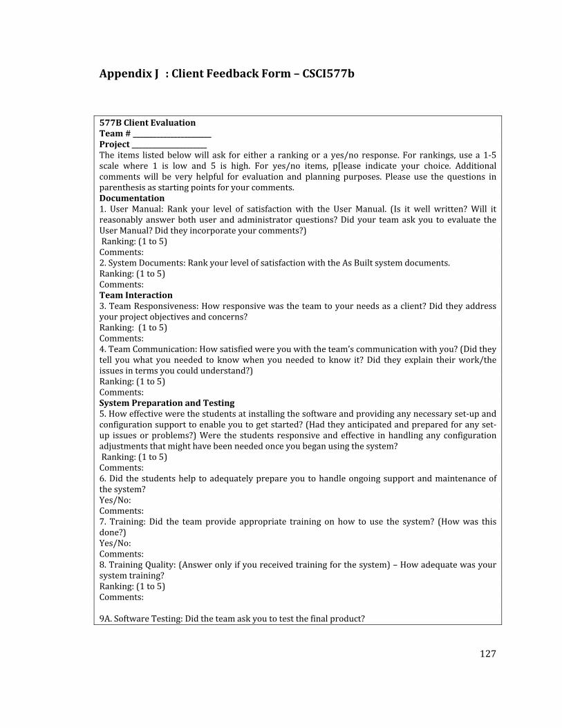
127
Appendix J : Client Feedback Form – CSCI577b
577B Client Evaluation Team # _______________________ Project ______________________ The items listed below will ask for either a ranking or a yes/no response. For rankings, use a 1‐5 scale where 1 is low and 5 is high. For yes/no items, p[lease indicate your choice. Additional comments will be very helpful for evaluation and planning purposes. Please use the questions in parenthesis as starting points for your comments. Documentation 1. User Manual: Rank your level of satisfaction with the User Manual. (Is it well written? Will it reasonably answer both user and administrator questions? Did your team ask you to evaluate the User Manual? Did they incorporate your comments?) Ranking: (1 to 5) Comments: 2. System Documents: Rank your level of satisfaction with the As Built system documents. Ranking: (1 to 5) Comments: Team Interaction 3. Team Responsiveness: How responsive was the team to your needs as a client? Did they address your project objectives and concerns? Ranking: (1 to 5) Comments: 4. Team Communication: How satisfied were you with the team’s communication with you? (Did they tell you what you needed to know when you needed to know it? Did they explain their work/the issues in terms you could understand?) Ranking: (1 to 5) Comments: System Preparation and Testing 5. How effective were the students at installing the software and providing any necessary set‐up and configuration support to enable you to get started? (Had they anticipated and prepared for any set‐up issues or problems?) Were the students responsive and effective in handling any configuration adjustments that might have been needed once you began using the system? Ranking: (1 to 5) Comments: 6. Did the students help to adequately prepare you to handle ongoing support and maintenance of the system? Yes/No: Comments: 7. Training: Did the team provide appropriate training on how to use the system? (How was this done?) Yes/No: Comments: 8. Training Quality: (Answer only if you received training for the system) – How adequate was your system training? Ranking: (1 to 5) Comments: 9A. Software Testing: Did the team ask you to test the final product?
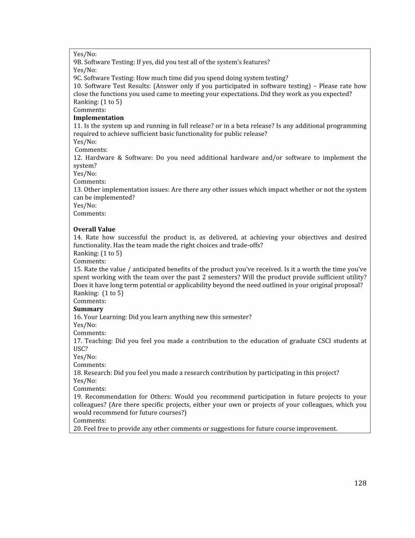
128
Yes/No: 9B. Software Testing: If yes, did you test all of the system’s features? Yes/No: 9C. Software Testing: How much time did you spend doing system testing? 10. Software Test Results: (Answer only if you participated in software testing) – Please rate how close the functions you used came to meeting your expectations. Did they work as you expected? Ranking: (1 to 5) Comments: Implementation 11. Is the system up and running in full release? or in a beta release? Is any additional programming required to achieve sufficient basic functionality for public release? Yes/No: Comments: 12. Hardware & Software: Do you need additional hardware and/or software to implement the system? Yes/No: Comments: 13. Other implementation issues: Are there any other issues which impact whether or not the system can be implemented? Yes/No: Comments: Overall Value 14. Rate how successful the product is, as delivered, at achieving your objectives and desired functionality. Has the team made the right choices and trade‐offs? Ranking: (1 to 5) Comments: 15. Rate the value / anticipated benefits of the product you’ve received. Is it a worth the time you’ve spent working with the team over the past 2 semesters? Will the product provide sufficient utility? Does it have long term potential or applicability beyond the need outlined in your original proposal? Ranking: (1 to 5) Comments: Summary 16. Your Learning: Did you learn anything new this semester? Yes/No: Comments: 17. Teaching: Did you feel you made a contribution to the education of graduate CSCI students at USC? Yes/No: Comments: 18. Research: Did you feel you made a research contribution by participating in this project? Yes/No: Comments: 19. Recommendation for Others: Would you recommend participation in future projects to your colleagues? (Are there specific projects, either your own or projects of your colleagues, which you would recommend for future courses?) Comments: 20. Feel free to provide any other comments or suggestions for future course improvement.

129
Appendix K : Qualitative Interview Form
Part 1: Information about COTS/ Services in your project Section 1: General info about your project 1. Name, team: 2. What is your client’s computer technology level
[ ] Low [ ] Medium [ ] High 3. What is your client’s role in this project (check all that apply)
[ ] End user [ ] Maintainer/ Administrator [ ] Policy Planner [ ] Acquirer [ ] Other, 4. What are the COTS/ Services you finally selected? 5. What are the functionalities of your selected COTS/Service? 6. What were on your choices? 7. What are the cost(s) of the selected C/S? 8. Does your selected C/S satisfy all the project goals? 9. If not, what are the part(s) that is left to develop? 10. Who introduced these C/Ss?
[ ] Client [ ] Development Team [ ] Other, ___________________________ 11. If client was not the one who introduced the C/S, what was his/her first reaction?
[ ] Oppose [ ] Hesitate [ ] Support [ ] Other, ___________________________________ 12. When did you introduce your C/S?
[ ] Exploration Phase [ ] Valuation Phase [ ] Foundations Phase 13. When did you finalize your C/S?
[ ] Exploration Phase [ ] Valuation Phase [ ] Foundations Phase 14. What were the process / steps in finalizing the C/S selection? Section 2: Criteria in selecting COTS/ Services 1. What kind of information you used to select the COTS/ Services? [ ] Core capabilities in OCD [ ] Business workflow in OCD [ ] Requirements in SSRD [ ] Use case in SSAD [ ] Current system infrastructure [ ] Proposed system infrastructure [ ] Prototype [ ] Business Case Analysis Anything else? 2. Where did you get information about these COTS/ Services? Section 3: Activities in each phase Section 3.1 Exploration Phase 1. Was C/S part of the project proposal? a. If yes, what did your client have any specific C/S in mind at the beginning? b. If no, did you plan to develop everything from scratch at the beginning, why? 2. When you read the project proposal, did you know that there is/ are possible C/Ss available for this project? 3. Any problem regarding C/S in this phase? Section 3.2 Valuation Phase 1. In this phase, did you switch to C/S team or still follow the traditional development guidelines? 2. Did you prioritize or reprioritize your criteria? 3. Did you build any prototype? 4. If your C/S is selected, did you tailor the C/S? 5. If your C/S is selected, did you write any glue code for the C/S?

130
Section 3.3 Foundations Phase 1. In this phase, did you switch to C/S team or still follow the traditional development guidelines? 2. Did you reprioritize your criteria? 3. Did you drop any criteria? 4. Did you build any prototype? 5. If your C/S is selected, did you tailor the C/S? 6. If your C/S is selected, did you write any glue code for the C/S? Section 4: Hypothetical Situations Part 2: EPG for COTS/Services 1. Are there any activities/tasks that you perform but they are not listed/ explained in CBA Guidelines? 2. Is there any role(s) that should be added? 3. Is there any work product(s) that should be added? 4. Is there any guideline(s) that should be added?

131
Appendix L : Results of ICSM EPG Survey
Table 29: Results of ICSM EPG Survey
I. Effective communication regarding the process AVG
1 The ICM EPG improves my understanding about software development process. 4.25
2 The ICM EPG enables my communication about software development process among team members. 3.84
3 The ICM EPG enables my communication about software development process with the client. 3.47
II. Peopleoriented process information
4 The ICM EPG provides essential information about software development process based on your role. 4.25
5 The ICM EPG helps me to understand responsibilities of each role with respect to the process. 4.28
6 The ICM EPG would help me in assigning tasks to each role, if I were the project manager 4.18
7 The ICM EPG helps me to select the role that I want. 3.77
8 The ICM EPG explains about activities in which each role has to participate. 4.21
III. Process modeling and support
9 The ICM EPG provides essential information for me to plan and execute my software development process. 3.92
10 The ICM EPG allows me to learn about software development process incrementally. 4.10
11 The ICM EPG provides information that supports me in process adaptation to fit with your project status. 3.53
12 The ICM EPG provides a framework for analyzing and estimating patterns of resource allocation and consumption in each phase of the software development life cycle.
3.56
13 The ICM EPG provides complete information about software development process in the Exploration phase 4.20
14 The ICM EPG provides complete information about software development process in the Valuation phase 4.16
15 The ICM EPG provides complete information about software development process in the Foundations phase 4.13
16 Information provided in the ICM EPG is consistent. 4.13
17 The ICM EPG provides information about activities that have to be accomplished to achieve process objectives.
4.26
18 The ICM EPG provides information about artifacts to be created and maintained. 4.35
19 The ICM EPG provides an outline for what artifacts to produce for delivery to client. 4.00
20 The ICM EPG provides information about tools to be used in the process. 3.26
IV. Process Improvement
21 The ICM EPG helps me to eliminate inconsistencies in the process specification. 3.82
22 The ICM EPG provides information about quality model (i.e., provide ideal artifacts) 3.80
23 The ICM EPG suggests the steps to be accomplished in order to improve the quality of a software process 3.62
24 The ICM EPG is easy to use. 3.91
25 The notations/graphic representations used in the ICM EPG are easy to understand. 3.84
26 It is easy to find specific information in the ICM EPG. 3.65
27 The ICM EPG has a high clarity of navigation. 3.65

132
Appendix M : Software Process Guidelines Survey
Software Process Guidelines Survey Objectives: 1. To gather feedback regarding the use of PDF‐version of MBASE/LeanMBASE guidelines 2. To compare the experience of PDF‐version of guidelines usage and the ICSM EPG usage MBASE Guidelines http://sunset.usc.edu/classes/cs577a_2004/guidelines/MBASE_Guidelines_v2.4.1.pdf LeanMBASE Guidelines: http://greenbay.usc.edu/csci577/fall2005/site/guidelines/LeanMBASE_Guidelines_V1.4.pdf Part I: Usage of PDFversion of MBASE/LeanMBASE process guidelines Regarding the pdf‐version of MBASE/LeanMBASE guidelines (PDF‐MBASE), please answer the following questions: Effective communication regarding the process
(low/ bad) (high/good) 1 2 3 4 5
The PDF‐MBASE improves my understanding about software development process.
The PDF‐MBASE enables my communication about software development process among team members.
The PDF‐MBASE enables my communication about software development process with the client.
Comments: Peopleoriented process information (low/ bad) (high/good)
1 2 3 4 5
The PDF‐MBASE provides essential information about software development process based on your role.
The PDF‐MBASE helps me to understand responsibilities of each role with respect to the process.
The PDF‐MBASE would help me in assigning tasks to each role, if I were the project manager
The PDF‐MBASE helps me to select the role that I want. The PDF‐MBASE explains about activities in which each role has to participate.
Comments: Process modeling and support (low/ bad) (high/good)

133
1 2 3 4 5
The PDF‐MBASE provides essential information for me to plan and execute my software development process.
The PDF‐MBASE allows me to learn about software development process incrementally.
The PDF‐MBASE provides information that supports me in process adaptation to fit with your project status.
The PDF‐MBASE provides a framework for analyzing and estimating patterns of resource allocation and consumption in each phase of the software development life cycle.
Comments:
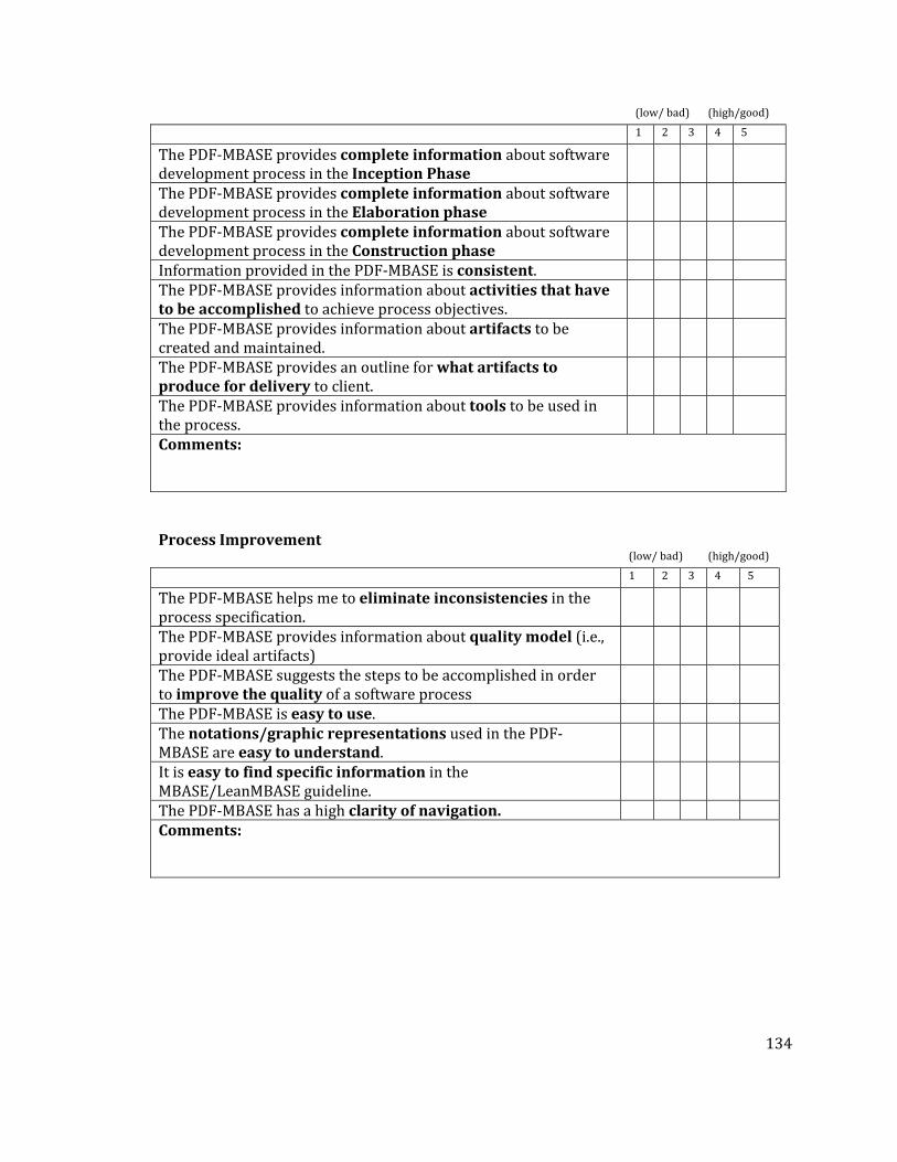
134
(low/ bad) (high/good)
1 2 3 4 5
The PDF‐MBASE provides complete information about software development process in the Inception Phase
The PDF‐MBASE provides complete information about software development process in the Elaboration phase
The PDF‐MBASE provides complete information about software development process in the Construction phase
Information provided in the PDF‐MBASE is consistent. The PDF‐MBASE provides information about activities that have to be accomplished to achieve process objectives.
The PDF‐MBASE provides information about artifacts to be created and maintained.
The PDF‐MBASE provides an outline for what artifacts to produce for delivery to client.
The PDF‐MBASE provides information about tools to be used in the process.
Comments: Process Improvement (low/ bad) (high/good)
1 2 3 4 5
The PDF‐MBASE helps me to eliminate inconsistencies in the process specification.
The PDF‐MBASE provides information about quality model (i.e., provide ideal artifacts)
The PDF‐MBASE suggests the steps to be accomplished in order to improve the quality of a software process
The PDF‐MBASE is easy to use. The notations/graphic representations used in the PDF‐MBASE are easy to understand.
It is easy to find specific information in the MBASE/LeanMBASE guideline.
The PDF‐MBASE has a high clarity of navigation. Comments:

135
Part II – Usage of the Incremental Commitment Spiral Model Electronic Process Guide (ICSMEPG) ICSM‐EPG: http://greenbay.usc.edu/IICMSw/index.htm ICSM EPG is a web‐based tool that is created to replace the pdf‐version of MBASE/LeanMBASE process guidelines. Please take a look at the link provided and answer the following questions Effective communication regarding the process (Do not agree) (Agree)
1 2 3 4 5
The ICSM EPG is better than the PDF‐MBASE in improving my understanding about software development process.
The ICSM EPG is better than the PDF‐MBASE in enabling my communication about software development process among team members.
The ICSM EPG is better than the PDF‐MBASE in enabling my communication about software development process with the client.
Comments: Peopleoriented process information (low/ bad) (high/good)
1 2 3 4 5
The ICSM EPG is better than the PDF‐MBASE in providing essential information about software development process based on your role.
The ICSM EPG is better than the PDF‐MBASE in helping me to understand responsibilities of each role with respect to the process.
The ICSM EPG is better than the PDF‐MBASE in assigning tasks to each role, if I were the project manager
The ICSM EPG is better than the PDF‐MBASE in selecting the role that I want.
The ICSM EPG is better than the PDF‐MBASE in explaining about activities in which each role has to participate.
Comments:
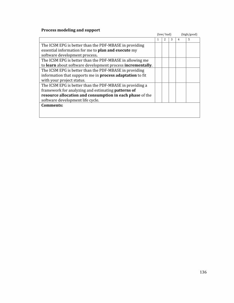
136
Process modeling and support (low/ bad) (high/good)
1 2 3 4 5
The ICSM EPG is better than the PDF‐MBASE in providing essential information for me to plan and execute my software development process.
The ICSM EPG is better than the PDF‐MBASE in allowing me to learn about software development process incrementally.
The ICSM EPG is better than the PDF‐MBASE in providing information that supports me in process adaptation to fit with your project status.
The ICSM EPG is better than the PDF‐MBASE in providing a framework for analyzing and estimating patterns of resource allocation and consumption in each phase of the software development life cycle.
Comments:

137
(low/ bad) (high/good)
1 2 3 4 5
The ICSM EPG is better than the PDF‐MBASE in providing complete information about software development process in the Inception Phase
The ICSM EPG is better than the PDF‐MBASE in providing complete information about software development process in the Elaboration phase
The ICSM EPG is better than the PDF‐MBASE in providing complete information about software development process in the Construction phase
The ICSM EPG is better than the PDF‐MBASE in providing more consistent Information
The ICSM EPG is better than the PDF‐MBASE in providing information about activities that have to be accomplished to achieve process objectives.
The ICSM EPG is better than the PDF‐MBASE in providing information about artifacts to be created and maintained.
The ICSM EPG is better than the PDF‐MBASE in providing an outline for what artifacts to produce for delivery to client.
The ICSM EPG is better than the PDF‐MBASE in providing information about tools to be used in the process.
Comments: Process Improvement (low/ bad) (high/good)
1 2 3 4 5
The ICSM EPG is better than the PDF‐MBASE in helping me to eliminate inconsistencies in the process specification.
The ICSM EPG is better than the PDF‐MBASE in providing information about quality model (i.e., provide ideal artifacts)
The ICSM EPG is better than the PDF‐MBASE in suggesting the steps to be accomplished in order to improve the quality of a software process
The ICSM EPG is easier to use compare to the PDF‐MBASE The notations/graphic representations used in the ICSM EPG are easier to understand compare to the PDF‐MBASE
It is easier to find specific information in the ICSM EPG The ICSM EPG has a higher clarity of navigation compare to the ICSM EPG
Comments: ICSM EPG PDF‐
MBASE As a process guideline, do you prefer ICSM EPG or PDF‐MBASE?

138
Appendix N : Results of Software Process Guidelines Survey
Table 30: Results of Software Process Guidelines Survey
I. Effective communication regarding the process 1. The PDF‐MBASE improves my understanding about software development process. 3.667
2. The PDF‐MBASE enables my communication about software development process among team members. 3.5
3. The PDF‐MBASE enables my communication about software development process with the client. 3.167
II. Peopleoriented process information 4. The PDF‐MBASE provides essential information about software development process based on your role. 3.667
5. The PDF‐MBASE helps me to understand responsibilities of each role with respect to the process. 3.5
6. The PDF‐MBASE would help me in assigning tasks to each role, if I were the project manager 3
7. The PDF‐MBASE helps me to select the role that I want. 38. The PDF‐MBASE explains about activities in which each role has to participate. 3.333
III. Process modeling and support 9. The PDF‐MBASE provides essential information for me to plan and execute my software development process. 3.333
10. The PDF‐MBASE allows me to learn about software development process incrementally. 2.667
11. The PDF‐MBASE provides information that supports me in process adaptation to fit with your project status. 2.333
12. The PDF‐MBASE provides a framework for analyzing and estimating patterns of resource allocation and consumption in each phase of the software development life cycle.
2.5
13. The PDF‐MBASE provides complete information about software development process in the Inception Phase 3.333
14. The PDF‐MBASE provides complete information about software development process in the Elaboration phase 3.333
15. The PDF‐MBASE provides complete information about software development process in the Construction phase 3.333
16. Information provided in the PDF‐MBASE is consistent. 317. The PDF‐MBASE provides information about activities that have to be accomplished to achieve process objectives. 3.333
18. The PDF‐MBASE provides information about artifacts to be created and maintained. 4
19. The PDF‐MBASE provides an outline for what artifacts to produce for delivery to client. 3.833
20. The PDF‐MBASE provides information about tools to be used in the process. 3.167

139
IV. Process Improvement 21. The PDF‐MBASE helps me to eliminate inconsistencies in the process specification. 3
22. The PDF‐MBASE provides information about quality model (i.e., provide ideal artifacts) 3.5
23. The PDF‐MBASE suggests the steps to be accomplished in order to improve the quality of a software process 2.833
24. The PDF‐MBASE is easy to use. 225. The notations/graphic representations used in the PDF‐MBASE are easy to understand. 3
26. It is easy to find specific information in the MBASE/LeanMBASE guideline. 2
27. The PDF‐MBASE has a high clarity of navigation. 2.5 Part II – Usage of the Incremental Commitment Spiral Model Electronic Process Guide (ICSMEPG) V. Effective communication regarding the process 28. The ICSM EPG is better than the PDF‐MBASE in improving my understanding about software development process. 4.167
29. The ICSM EPG is better than the PDF‐MBASE in enabling my communication about software development process among team members.
4.167
30. The ICSM EPG is better than the PDF‐MBASE in enabling my communication about software development process with the client. 4
VI. Peopleoriented process information 31. The ICSM EPG is better than the PDF‐MBASE in providing essential information about software development process based on your role. 4.667
32. The ICSM EPG is better than the PDF‐MBASE in helping me to understand responsibilities of each role with respect to the process. 4.5
33. The ICSM EPG is better than the PDF‐MBASE in assigning tasks to each role, if I were the project manager 4.5
34. The ICSM EPG is better than the PDF‐MBASE in selecting the role that I want. 3.667
35. The ICSM EPG is better than the PDF‐MBASE in explaining about activities in which each role has to participate. 4.667
VII. Process modeling and support 36. The ICSM EPG is better than the PDF‐MBASE in providing essential information for me to plan and execute my software development process. 4.667
37. The ICSM EPG is better than the PDF‐MBASE in allowing me to learn about software development process incrementally. 4.333
38. The ICSM EPG is better than the PDF‐MBASE in providing information that supports me in process adaptation to fit with your project status. 4
39. The ICSM EPG is better than the PDF‐MBASE in providing a framework for analyzing and estimating patterns of resource allocation and consumption in each phase of the software development life cycle.
4.167

140
40. The ICSM EPG is better than the PDF‐MBASE in providing complete information about software development process in the Inception Phase 4.167
41. The ICSM EPG is better than the PDF‐MBASE in providing complete information about software development process in the Elaboration phase 4.167
42. The ICSM EPG is better than the PDF‐MBASE in providing complete information about software development process in the Construction phase
4.167
43. The ICSM EPG is better than the PDF‐MBASE in providing more consistent Information 3.833
44. The ICSM EPG is better than the PDF‐MBASE in providing information about activities that have to be accomplished to achieve process objectives. 4.5
45. The ICSM EPG is better than the PDF‐MBASE in providing information about artifacts to be created and maintained. 4.333
46. The ICSM EPG is better than the PDF‐MBASE in providing an outline for what artifacts to produce for delivery to client. 4.5
47. The ICSM EPG is better than the PDF‐MBASE in providing information about tools to be used in the process. 3.5
VIII. Process Improvement 48. The ICSM EPG is better than the PDF‐MBASE in helping me to eliminate inconsistencies in the process specification. 3.833
49. The ICSM EPG is better than the PDF‐MBASE in providing information about quality model (i.e., provide ideal artifacts) 4
50. The ICSM EPG is better than the PDF‐MBASE in suggesting the steps to be accomplished in order to improve the quality of a software process 4
51. The ICSM EPG is easier to use compare to the PDF‐MBASE 4.66752. The notations/graphic representations used in the ICSM EPG are easier to understand compare to the PDF‐MBASE 4.167
53. It is easier to find specific information in the ICSM EPG 4.554. The ICSM EPG has a higher clarity of navigation compare to the ICSM EPG 4.833
EPG PDF
55. As a process guideline, do you prefer ICSM EPG or PDF‐MBASE? 100% 0%