the dfsign and construction of a multiple disk turbine · extensive theoretical analysis of the...
TRANSCRIPT

THE DFSIGN AND CONSTRUCTION
OF A MULTIPLE DISK TURBINE
by Abdel Moneim Mohd Abdel Razig Sudan
Training in Alternative Energy Technologies Session 7 June 2 1983
THEORY
Design data for the turbine came from the extensive
work of Professor Warren Rice of Arizona State University
Tempe Arizona The mathematical analysis of the fluid
flow and computer analysis have been used to develop
the pertinent data for a pump water turbine and steam
turbine The fluid for our turbine is considered Newtonian
incompressible and the laminar flow of most practical
interest
The essential part of the fluid flow is between a pair of
co-rotating disks The momentum of thu moving fluid is
transferred to disks due to the effects of viscosity and adshy
hesion The friction force of the fluid transfers this
momentum Low-pressure low-velocity fluid is exited out
of the center (Fig 1)
The turbine constructed consists of 30 disks and spacers
Each disk being 12 inches in dianeter with an exit port of
36 inches The metal disks are of galvanized steel 020
inches thick and the spacers are made of steel shim stock
010 inches thick The turbine also consists of a fluid
supply nozzle exit ports rotor housing casing and shaft
bearings
The high pressure fluid is converted to high velocity
fluid at the nozzle The moving fluid flows between a pair
of co-rotating disks Due to the effects of viscosity and
adhesion there is a force component in the direction of the
-1shy
direction of the fluid tangentially and an outward
centripical force due to the rotation of the disks The
pressure gradient between the inlet and outlet ports forces
the fluid to spiral toward the center exit port The combinashy
tion of these forces creates the not torque on the rotor
INTRODUCTION
The conceptiun and development of multiple-disk
turbomachinery is credited to Nikola Tesla Patents covering
the multiple disk turbine and pump were granted to him in May
of 1913 These devices were widely discussed in the semishy
technical press of that time
In 1972 Walter Baumgartner buiJt an experimental model
turbine which ran on compressed air and produced 30 horseshy
power at 18000 rpm
Presently the Tosla turbine is under development by
Sun Wind Ltd uf Sebastopol California Sun Wind plans
to use the turbine burning hydrogen in a three wheel car
The turbine can also burn propane vegehol and gasoline
Another California company General Enertech of San Diego
is building and selling the Tesla pump which has been
improved and modernized
Extensive theoretical analysis of the Tesla turbine has
been carried out over the past 20 years by Prof Warren Rice
of Arizona State University in Tempe Arizona His paper
Calculated Design Data for the Multiple Disk Turbine Using
Incompressible Fluid was used extensively in our turbine model
-2shy
RESULTS
The turbine was tested using a supply pressure which
varied from 0 - 50 psi The maximum rpms obtained was 220
The power output was calculated to be approximately 05
horsepower Different values of pressure were tried and at
each value rpm readings were taken
CONCLUSION
The turbine did not perform as well as expected due to
several reasons The rotor was not perfectly round and
rubbed at one spot in the housing The high perssure ring
seals caused too much friction and had to be removed thereshy
fore a good pressure gradient could not be obtained The
disks were slightly warped in spots closing off some of the
passage ways thereby stopping fluid flow bet- the pair of
disks
Despite these problems this turbine does have
advantages in case of production low cost and low
maintenance
-3shy
moFeurocie muIi t 1( uo~
I k cvmchpiT apptie
-a--- awnele
Q 11-ilame A oamp4 ekweeAtAAamp IO~vamp o~
FO cr
acdt ocl bd-cca poivZoe
C)
Calculated Design Data for the Multiple-Disk Turbine Using Incompressible Fluid
Graduate Studentpresently Major U S Army
Earlieranal saeof the laminarradially inward throughflow of Newtonian incompresshysiblefluid between parallelcorotatingdisks have been used to caculate the performanre of multiple-disk turbines using such flow passages as the rotor Such turbines areW RICE characterizedby certaindimensionlessparametersznd a large number of computerized
Professor Morn ASME calculationshas enabledpreparationof turbineperformancs maps for turbinesidealied Mechanical Engineering as having no losses external to the rotor (except for asumed zerc pressure recovery inArizona State University the turbineexhaust) These maps show the quantitatii dependence of turbineefficiencyTempe Ariz total pressure and delivered power on the turbine geometry and speed the turbine
nozzle direction and pressuredrop and on the fluid propertiesfull admission around the periphery of the rotor is assumed Conventional loss informationfor the nozzlesand conventional bearing seal and disk friction loss information must be cpplisdin the design process to provide prediction of actual turbina performance and conshyparison with conietional turbines
Introduction
The conception of multiple-disk turbomachinery is credited to N Tesls early in this century [1-311 and the devices were widely discussed in the semitechnical press of that time (4-71Subsequently such turbormachinery received scant attention for many years but the list of references included in thin paperindicates the extent of a revival of interest A number of ex-perimental and analytical feasibility studies have been reportedfor the turbine configuration of multiple-disk turbomachinery[8-15) The papers reporting on these studies make the operating principle clear and indicate that laminar flow of fluid in the rotor rather than turbulent flow is of the most practical in-terelt
A recent sequence of analytical contzibutions has made poe-sible calculation of the performance of multiple-disk turbines according to an idealized model provided that the fluid is Newtonian and incompressible and that the flow is laminar The essential part of the flow in a multiple-disk turbine is that between a pair of corotating disks the turbine consists of a number of such flows in parallel together with fluid supply
Noab in br o d o Re e at end of paper
C eUbted by the Fluids Enginering Division of Tax Aurnhtc~m Socmr or MawcxgArcL Eovuraa and presentd at the Joint Fluid Eanging ampCSME Coereme Montral Qube Canada May 13-15 1974 Mnuseipt WWsvd at ASME Hmdquarna February 1974 Paper No 74-FE-
252 SEPTEMBER 1974
nozzles an exit port andor diffuser and a suitable housing and bearings The laminar flow of fluid between a pair of disks conshysists of an entrance region in the outer radial zone near the noxshyzles and an asymptotic flow region at inner radii remote from the nozzles Peube and Kreith [161 provided a truncated series typeanalysis for the asymptotic region of radially outward flow beshytween corotating disks descriptive of the flow in a multipleshydisk pump The results are easily adapted to the asymptotic region for radially inward flow corresponding with a multipleshydisk turbine but fail to describe the flow at small radii with sufficient accuracy particularly with regard to the pressure dropsuffered by the flow An iterative solution for the asymptotic region of radially inward flow between coratating disks corshyresponding with a multiple-disk turbine by Matsch and Rice [171 provided a more definite (but still limited) flow description the paper referenced details the importance of the conceyt of the asymptotic flow region and of the progrnmion of the velocityprofiles to a final inflection of the radial compnent of the velocity at a predictable inner radius Two parameters are necessary to specify an ampAymptotic flow case One is a so-called Reynoldsnumber Nan which is dimensionless and depends on fluid propshyerties angular velocity of the disks and the spacing between the disks The second is a flow rate parameter U which is dishymensionless and depends on the volume flow rate of fluid beshytween a pair of disks the agular velocity of the disks and the outer radius of the rotor It is clear from the referenced papersthat knowledge of the Asymptotic region alone is not sufficient to determine the performance of a multiple-disk turbine since large pressure changes and contribut as to the torque occur inthe entrance region before the asymptotic flow region is reached
Transactions of the ASME
U
3 3
2 ___ _
dego
o 0shy
0 4 NRE a 0 4 NRE 8 FIg I Consto t efficiency lines on NRE U coordinates for Vq-11 Fig 2 Constant dimenslonless total pressure lines on NRE U Coshyri- and parabolic Inlet velocity dlstrlbutlow ordinates for V-L ri-03 and parabolic Inlet distributions
A numerical (Fnite-difference) scheme for calculating the en- tions of the velocity components at the outer radius P (provided trance flow between corotating disks for radially outward flow by the nozzles to the rotor) are considered arbitrary but specified corresponding with a multiple-disk pump was presented by and these are additional parameters for the specification of a Breiter and Pohlhausen [181 A similar method of calculation case of flow in the entrance region between the disks was applied for radially inward flow corresponding with the Furthermore [191 introduces a simplification in the paramshymultiple-disk turbine by Boyd and ilice [191 the fluid was con- eterization with the general shape of the disk-to-disk vlocity sidered admitted uniformly around the outer periphery of the component profiles specified (uniform parabolic etc) then the disks through nozzles providing tangential radial and axial three parameters NRE US and V are sufficient to characterize components of velocity In 119] the disk-to-disk spatial distribu- a case of entrance region flow Here Vo is the average value of
-- Nomenature
Dimnsional Quantities 2 f n Q disks in set of disks corn-
H- operating head for turbine - shyh 2WA posing a turbine rotorlength
h - spacing between adjacent average value of radi-l com- NRc -PM3 Reynolds number disks length ponent of velocity at rotor AL
p - pressure change in nozzles entrance (nozzle exit) p -PpIPdeg 2force(length)2 lengthtime P -PPQr deg
Pr - pressure chauge through rotor 0 - V(F 2) - tangential com- P shyforce(length)2 ponent of velocity distribu- r - rr
pi - stagnation pressure change tion lengthtime -T pfo10 n
through turbine force 2 I u - u(r z)- t(f 2)f
(length) to - ()d2 - average value U - GA- Q volume P - delivered turbine of tangential component of 0power to 2flh
rotor force-lengthtime velocity at rotor entrance flow rate parameteir Q- volume flow through entire (nozzle exit) lengthtime v - v(r z)- D(F2)f
turbine (lengthPtime 9)(f 2) - axial component of velocity w - w(r z) - th( )2 Q - volume flow between pair of distribution lengthtime V - PfW - tangential velocity
adjacent disks (length) I axial space coordinate length parameter time p - density of fluid mass(length)r Z - ih
P- radial coordinate length - viscosity of fluid force-time T efficiency A - torque applied by fluid be- (length) u 2rUp
tween onc pair of disks i- angular velocity of rotor rad force-length (time) Subscripts
il - 0(P 1) - radial component of i - inner (exhaust) radial station
velocity distribution length Dimenionles Quantities o - outer (nozzle exit rotor enshytime N - number of spaces between trance) radial station
Jounal of Fluids Engineering SEPTEMBER 1974 253
z2 00shy
75
5 -
1101
0 4 NRE 8 Fig 3 Constant dimensionless torqlue lines on NRE U coordinates for V-LI ri-03 and parabolic Inlet velocity dlstrlbuons
the velocity of thethe dimensionless tangential component of
flow supplied by the nozzles to the rotor corresponding with the of conventional turbine practice
fluid-to-blade velocity ratio
The calculation procedure detailed in [191 also is applicable for the limitation in ac-the asymptotic flow region and overcomes
uzracy in the earlier methods of calculating that region The
disadvantage of the method is the excessively lengthy computa-
tion time required by digital computer
3
bulloo -- - 0
I54 1974TrasactionSPTEMBER
sO408 Irl 4I~lfoesn~ d tafV - 8- 3inpriliInevlo-
2 a4 ER14 N5t 8 4
11b 2 7
deg IU _______________________
so
OC0
0 4 Nit 8 Fig 5 Performance data for V-l0 tj-03 and parabolic Inlet Velec-Ity dlistributions
The adequacy of the calculation model and of the numerical
computations was confirmed experimentally by Adams and Rice
(201 Boyack and Rice [211 developed an integral method for the
flow model used by previous investigators and a computer proshy
gram which axecutes extremely rapidly The method yields
results essentially identical with those of the lengthy computashy
tions of references (18 19 and therefore aro confirmed experishymentally in reference (20 Use of this computer program enabled
ases necessary to
obtain the design data presented herein Crawford [221 improved calculation of the very large aumber of flo
the ability of the method of Boyack and RiLe to handle uniform
4o
Y I
of he SM
20
- ndprbicnetel-FI rfreedtafrV-J
0 Tr ntooft he A8M
3
I
00 bull l bull
II -- P 1
10 I
-Uo
202 t bullbull - 0shyP-6bull05 --ft0-t 0 3 _
I o80 0
4 0 o
o ~
0 4 NnE 8 Fig 7 Performance data for Ve-13ri-04 and parabolic Inletveloc-Ity dlstributlons
inlet profiles exhaustively examined the correctness of results
in the entrance region and also further decreased the execution
time raquired for digital computation by improved programming
Model of Turbine for Calculations
The mathematical model and calculation procedure for the flow betwecn a pair of corotating disks is that used by Boyack and Rice [211 discussed above The multiple-disk turbine con-
of many such corotating disks arranged on a common shaft
with the flow passages in parallel The choice of the number of
disks is determined by individuel design requiremerts the de-
sists
sign information presented herein is based on the flow between
a single pair of corotating disks The flow is considered to be a
laminar flow of an incompres ole Newtonian fluid The calcula-
tions provide realistically for the thermodynamically irreversible flow effects in the space between the disks The pressure change in the flow between the disks p is composed of that due to radially-incurred area change (with consequent velocity change)
and that due to irreversible (viscous) effects The dimensionless parameters NRE U and V for the flow
between a pair of corotating disks carry over to become also the
independcnt parameters for the turbine model The turbine is
assumed provided with nozzles around the entire periphery of the rotor (full admission) The nozzles provide the specified values
of U and V to the space between a pair of disks from a plenumchamber having the dimensionless stagnation pressure p The stagnertion ngpressure nsioiseassumednaticonservedrepinitnthe
that is the flow in the nozzles is con-zles in the turbine model
sidered to be thermodynamically reversible Part of ps is the dimensionless pressuredrop in the reversible nozzles p given de l pfrom by
1 fIn +
- SJ [u 2 (z) + u2(z)]u(z)dz (1)
where the contribution due to w(z) is considered to be negligibly
small It is seer that p depends on the disk-to-disk distribution
of the velocity -npoLents The fluid can supplied to the rotor of a multiple-disk turbine
Journal of Fluids Engineering
06
bullbull ~mk
- e b p
adeg0 004
--- --o
40
-ISO
o - shy
o ___- ______shy
4 N i 8
Fig$ Performance data for Ve-1 fs-03 and unlfoem Inlet velocity profiles
through nozzles arranged in various ways On the one hand a
separate nozzle ring may be provided for each disk space in
this case the disk-to-disk distribution of the velocity components u(z) and v(z) will be approximately parabolic On the other
hand the nozzle ring may consist of slots extending across the
rotor or at least accoss several disk spaces in this case disk-toshydisk distribution of the velocity components u(z) and u(z) will be approximately uniform
As an idealization considered of interest in prctice the disshytribution of u(z) and v(z) assumed herein is parabolic generally only where specifically noted later the distribution is assumed uniform in order to demonstrate the effect of the distribution on the performance of a multiple-disk turbine However in apshy
plications the disk spacing frequently is so small that separate nozzles are impractical and a single admission slot must be used The uniform distribution is then a better idealization of the
supply flow In the turbine model the fluid is considered to exhaust from
the rotor into a stagnant exit plenum chamber without the
benefit of an exahust diffuser Thus with the nozzles considered to be supplied with fluid from a stagnant condition
p- p + p (2)
and is the dimensionless stagnation pressure difference reshy
qnd acrs the dimensional ue d ie ie qued across the turbine The dimensional quantity ps is thenproperthedenominatoravailable for the expression of turbine efficiency ienergy of the fluid per unit mass and is th
The torque delivered to the rotor by the fluid can be calculated use of theby two fundamentally different means both involve
As one possibilitycalculated velocity field between the disks the local shear stress over the surface of the disks can be derived
the velociiy field and fluid properties and hence the local torque due to the shear force can be integrated over the surface
of the disks to obtain the rotor torque for the flow between a
pair of disks As an alternative a finite control volume can be used between the entrance and exit radii and the torque can be
calculated from the change of the moment of momentum of the
fluid between those radial stations The latter procedure is
used here since it is more direct and accurate mainly because it
avoids differentiation of the fluid velocity profiles The dimen-
SE PTE M B E R 1974 255
0 6 -4r I I
80
0 4 0 0a -6o 81
O I 0
0 I --- ___ 1__ II I
0 4 Ntc 8 ri ngI Performance data for V -L ri-04 and uniform inlet velocity FIig14 Turbineofficlencys a function ofr with Nau as parametewpreItl for Vs1 U--042 and parabolic Inlet velocity distributions
the performance of actual turbines A design example given later herein includes references for such loss information
sionless torque Tt (for one space between a single pair of disks) is also the dimensionless work delivered to the rotor by the fluid Results-Design Information Summaryand is given by
The computer program was executed for a very large number T - 4r ts u(r z)u(r )d-- ( ( 3 oi combinaions of Naz U and V each yielding values of
pi T and q for values of r such that 1 r 005 The results were cross-plotted by hand in order to produce data for plottingHence the turbine efficiency is given by lines of constant p T and 17for a fixed value of ri and of one
T input parameter and using the remaining two input parameters7 -- (4) as coordinates A large amount of judgment was exercised in2rUP making additional computer program executions to fill in
The computer program used to implement the analysis of Boyack and Rice (211 was arranged to accept Nit U and V as input parameters with the shape of u(z) and v(z) specified i and to calctate p Ti and 71as output results for selected dishymensionlesa exit radii ri such that I _ 005 with Art 005ri_ -Thus each combination of input parameters corresponds with 0_ _r 62 Nim an infinity of dimensionless turbines having different exit radii furthermore each combination of Nni U V and ri correspond with an infinity of dimensional1 (actual) turbines
The turbine model does not allow for resisting torques acting on the turbine rotor due to rotor-to-housing disk friction bearings seals etc Furthermore the model ignores pressure losses t itwill occur in an actual turbine due to interference of the disk edges with the Lozzle exit flow and due to irreversibility 60 4 in the nozzle flow and due to exit passage arem changes and frictional losses (The latter loss may actually be a gain if I the exit passage can be designed to produce a pressure recovery from the kinetic energy exhausting from the rotor since the tur1 ine model asumes no such pressure recovery)
rhe design information presented thus far therefore accounts for losses only in the flow between the disks and leaves to the 4C designer the taks of accounting for the loss of torque and efshyficiency due to nozzle efficiency nozzle-rotor interference rotorshyto-housing disk friction bearings and exhaust passage presshysure change The pressure efficiency and torque values givcn herein ae therefore upper limits of the performance of actual 0 4 ri 8 10 multiple-disk turbines and must be used with conventional loss Fig U Turbin efficiency aa a function f r with NRZaa a Parameterinformation for the turbir e parts external to the rotor to calculate for V-L3 U--0u2 and parabolic Inlet velocity dlstributioila
256 SEPTEMBER 1974 Transactions of the ASME
- -
-- 002 (These are reasonable and inshyfor V - 11 and U these parameters) The optimum innertereeting vJues for5001C ~oo
and is approximately_ltNal radius is approximately 03 for 3
shows that the greatest efshy04 for Nnz - 1 the figures alsoIV___HEAD 4 for this parameter combinition An-ficiency occurs for Nuz
POWER I0
100- 400 and increases the value of rt for40 increased value of thq volume flow rate parameter reduces the
at all values of NRzefficiencyEFFICIENCY1 maximum efficiency00 is detailed - 0 80 The effect on efficiency of an increased value of V
z00 -O lt The maximum efficiency is someshywht decrewsed by the higher value of V but the turbine charaoshy- 002
U0 Z - in Fig 11 for U shy 00-080 0
teristics are generally unchanged O a contained in the
Further details conce-Ding these matters 6 0 bullw and Nzu - 4 maximum f-
U report 123l For U- and to cuse the local maximum 110 4uW above 03 is to reduce efficiency 002
io o and the effect of increaing r60- z 20 ficiency occurs near V - 10 200
of V Furthermore both Tefficiency to occur at higher value
4 0 and p an almost-linear functions of V increasing as r is deshy
range changing the NRz
cresed Throughout the parameter 00 performance quantitatvely but all
100 20 values changes the turbine remain similar to those for Nhz - 4 R2 0--otrends to the flowto realize that the results pertain
00 - It is necessary be-U a turbine with N Lpaoee a single pair of disks for 5-N2KS-between Q-N200
0- 0VOLUME FLOW I00 RATECI-M 00 tween disks ((N + 1) disk) the total flow rte Qwillibe FLO 10 RTEFM0- VOUME 5
a Q-Ni-N2r9 an actual water turbine with
Fig U1 alculated perforavisce for and the power delivered to the rotor by the fluid will be rotor dia of U1In
(6)P - NTwpdhfl
can be found alternatively from the equationwhichdata points wherever
with definite additionalthe cromplota (7) to be large during the crosplotting P
rates of change were found (7) refer to the power delivered to the
Both equations (6) and Typical results are shown in Figs 1 2 and 3 which give lins
rotor by the fluid the shaft power will be less because of rotor-
T and 17 using U Na coordinates Alsoand for of constant p to-housing disk friction bearing losses seal losses etc
V - 11 and r - 03 and for parabolic velocity profiles at the for an actual turbine the stagnation pressure required will be
large number ofa rotor entrance (nozzle exit) From very
more thai p becasue of irreversible piessure changes in the fluid
plots such as those of Figs 1 2 and 3 dimensionless performance supply nozzles and between the nozzles and the spaces between
the actual turbine efficiency will be maps were produced the disks Consequentlyvoluminous beyond The designer
The dimensionless performance -maps are somewhat less than that indicated in the figures
the possibility of joumal publication They are available in the will allow for these facts in the use of the design data to predict
areThe results given therei form of a University Report [231
turbine performanceto four values of the param- in estimatshy
in four groups arranged according There arm numerous sources of information of valu
eter V 08 10 11 and 13 This is thought to be the useful various losses General design features and the pershy
with the values of most interest ing the axe reviewed in references
and interesting range for V formance of bearings seals and nozzki-
The data for each value of being near and just exceeding unity [(261 give sufficient detail concerning
and Nec[24 251 Daly have ri as a parameter and are presented in the form of sets
to allow optimization of the V the rotor-to-housing disk friction
of lines for constant pl T and 71on U NRE coordinates clearance and estimation of the power Ices from that source
of the results referenced Figs 4-7 present typical samples
have parabolicallywhich the turbinesfor the cse in An Example of Turbine Design and Performanceabove the rotor entrancevelocity components at
shaped disk-to-disk voluminous results in
The Report [231 also gives(nozzle exit) can be used toUsing the reference mtrial ealier cited and the data in the
a very simple digital computet piogram form for turbines having uniform disk-to-disk velocity figuresthe same at the rotor entrance Typical samples of these re-
determine the physical dimensions of turbines and the perform components
9 Comparison of the various As an example it is assumed that a water suts are presented in Figs 8 and ance characteristics
12 lioraSewjr whenshaft results yields information concerning the effect of the shape of the
turbine is desired which will produceof waterAThe obtaining
on turbine performance at 1000 rpmwith a total head of 130t of entrance profiles for other operated efshy
similar results a comprolilOand of is chosen as the results in the Repurt [231 suitable design point
ease of executing design details the parameter values is expensive in terms of digital computer usage
the ficiency physical size and inshyfor further analysis of should bethe need arbitrary and several
but once done eliminates only very design point is somewhat point chosen isturbine In this case theof a multiple-disk the designerflow within the rotor
apply the rults vestigated by It is further assumee modest algebraic calculations are needed to N - 4 andir - 030
to supply fluid the deaign of multiple-disk turbines ts
that the -illue wel esigned nozzlesturbineto
an approximately parabolic disk-to-disk disshy
to the rotor with carbon ring seals and conventional bearshytribution of velocityDiscussion ings and will have the optimum casing-to-rotor clearance for
Some insights into multiple-disk turbine design characteristics least disk friction
of the performance results result n a turbine are afforded through cromsplotting The foregoing assumptions and choices
Fig 10 presents the dependency of turbine efficiency on the di- a rotor exhaust dia of 36 in and s a parameter having a rotor dia of 120 in
menasionlesa inner (exhaust) radius ri with NZ
SEPTEMBER 1974 25 7
Journal of Fluids Engineering
479 disks spaced 00083 in apart If a disk thickness of 0004 in is arbitrarily chosen this results in a rotor with an axial length of 1ampjp the total volume of the turbine is approximately 1200 cu inincludirj the turbine casing and other structure
The performance haracteristics are shown in Fig 12 The very small disk thickness used in this design example isrealistic each disk carries very small torsional and radial load-
ing and no axial loading The disks can be spaced correctly and the rotor made more rigid by dimpling the disks to achieve the required average disk spacing
In this example the maximum turbine efficiency is approxi-mately 81 ercent and occurs at lowest flow rate and highest speed This value of efficiency is by no means the maximum achievable in multiple-disk turbines A different choice of the design point or of speed power or head at the design point will result in a different set of performance curves and characteristics
As an extension of the foregoing example it is considered that the turbine is to b designed to use a light oil (p 54 lbftsv - 00001 ft3sec) rather than water (p - 623 lbft3 shy00000106 ftsee) All other specifications being the same the oil turbine requires 197 disks and has a spacing between the diskn of 002345 in results in a rotor length of 541 inand an effiency of 076 and volume flow rate of 75 cfm at 1000 rpm and 130 ft bead The computerized evaluation programwould easily generate the off-design point characteristics of this turbine aliso
In contrast with conventional turbines the performance of the rotor and hence good e3timates of the turbine characteristics can be realistically calculated for multiple-disk turbines for both design point and off-design point operation with case using onlyalgebraic calculations
Conclusion
While the design data presented herein are sufficient to allow calculation of the performance of multiple-disk turbines and corn-parison with conventional turbines the deiigner will finally want more detail of the flow field between the disks At such point of interest the designer should use references [21 221 to obtain a computer-oriented analysis which eusily and economical-ly yields the desired detailed flow information
Further details concerning the generation of the cross-plots and of design procedures are given in a thesis by Lawn [271 s well a the Report (231
The multiple-disk turbine con be designed with high efficiencyfor fluid with any viscosity and density it remains to be estab-lished by further investigation and by practice whether or not the turbine has substantirl advantages when compared with conventional turbines in the various extremes of application For all of the data presented herein it is assumed that the flow in the rotor is laminar Itisknown from investigation byAdams and Rice (201 that laminar flow occurs in the flow b-tween rotating disks over a wide range of the flow parameters The criteria for prediction of laminar and of turbulent flow has been established for multiple-disk turbines it is known at this time that laminar flow persists to high value of VnF for low values of U and to high values of U for low values of Nrhigh values of both parameters promote turbulent flow Detals and Nece R E Chamber Dimensiong vEffects on Induced Flow and Frictional Resistance of Enclosedof the delineation of the laminar region and of the experimentsleading to it are available in a University Report [281 and will appear subsequently in a journal publication
References 1 Tesla Nikola Turbine United States Patent No1061206 May 6 1913
258 SEPTEMBER 1974
2 Popovic Vojin Horvat Rodoslav and NicolYc NikolaisNikola Tesla 1856-1943 Lectures Patents Articles NikolaTesla Museum Beograd 1956 3 Tesla Nikola Fluid Propulsion United States Patent
No 1061142 May 5 1913 4 The Tesla Steam Turbine Scientific American Septemshyber 30 1911 pp 296-297 5 Bladeless Turbines Engineering (of London) Nov 101911 p 637 6 Mergeault E Lea Turbines i Frottements ou Turbines
Tesla Revue de Mecanqe June 1914 pp 538-544 7 Thoeryr of the Tosla Turbine Engineering (of London)April 16 1915 p 4258 Schroeder HB An Investigation of Viscosity Force
in Air by Means of a Viscosity Turbine MSthesis Rensselaer Polytechnic Institute Troy N Y 1950
9 Leaman The Design Construction and Investishygation of a TeslaA BTurbine MS thesis Uni-tersity of Maryland College Park Md 1950
10 Armstrong J H An Investigation of the PerformAnce of a Modified Tesla Turbine MS thesis Georgia Institute of Technology Atlnta Ga 195211 Young S K The Investigation and Analysis of theTesla Turbine MS thesis University of Illinois Urbana Ill 1957 12 Grubei E L An Investigation of a Turbine withMultiple-Disk Rotor MS athesis Arizona State UniversityTempe Ariz 1960
13 Rice W An Analytical ed Experimeril Investigation of Multiple-Disk Turbines Journal of Engineering for Power TRANS ASIME Vol 87 Series A No 1 Jan 1965 pp 29-36
14 Beans W E Investigation Into the PerformanceCharacteristics of a Friction Turbine Journal of SpacecraftVol 3 No 1 Jan 1966 pp 131-134
15 Nendl D Eine theoretische Betrachtung der Reibungsshyturbomaschinen vn Nikola Tesla Doktor-Ingenieurs dissertashytion Lehrstuhl fir Technische Hochschile Aachen July 196616 Peube J -L and Kreith F Ecoulement permanentdun fluide visquex incompressible entre deux disques paralleles en rotation Journal de Mecdnique Vol 5 No 2 June 1966
17 Matsch L and Rice W An Asymptotic Solution forLaminar Flow of an Incompressible Fluid BetweenDisks RotatingJournal of Applied Mechanics Vol 35 TRANs ASMEVol 90 Series E No 1 Mar 1968 pp 155-159 18 Breiter M C and Pohlhausen K Laminar Flow Beshy
tween Two Parallel Rotating Disks Report No ARL 62-218 Mar 1962 Aeronautical Research Laboratoriesson Wright-Patter-Air Force Base Dayton Ohio19 Boyd K E and Rice W Laminar Inward Flow of an Incompressible Fluid Between Rotating Disks With Full Perishyheral Admision Journal of Applied Mechanics Vol 35 A 20
sASME Vol 90 Series E No 2 June 1968 pp 229-237Adams R G and Rice W Experimental Investigationof the Flow Between Co-Rotating Disks Journalof Applied Mechanics Vol 37 TRANS ASME Vol 92 Series E No 3 Sept 1970 pp844-849
21 Boyack B E and Rice W Integral Method for FlowBetween Corotating Disks Jorunal of Basic EngineeringTRANS ASME Vol 93 Series D No 3 Spet 1071 pp 350-354 22 Craword Michael Edward A Composite Solution
Method for Analytical Design and Optimization Studies of a Multiple-Disk Pump MS thesis Arizona State UniversityTempe Ariz June 1972
23 Lawn John Michael Jr and Rice Warren CalculatedDesign Data for the Mltiple-Disk Turbine Using Incompressible Fluid Report No ERC-R-73004 Engineering Research Center Arizona State University Tempe Ariz
24 Adolph Max Strdmungamashinen Springer-VerlagBerlin Germany 1965 25 Barrows H K Water Power EngineeringThird Edition
McGraw-Hill New York 1943 26 Daly J W
Rotating Disks Journal of Engineering TRANS ASME Vol 82 Series D No 1Mar 1960 pp 217-232
27 Lawn Michael John An Investigation of Multiple-Disk Turbine Performance Parameters thesis Mechanical Engineershying Arizona State University Tempe Ariz June 197228 Pater Larry L Crowther Errett and Rice WarrenFlow Re me Definition for Flow Between Corotating DisksReport No ERC-R-73009 Engineering Research CenterArizona State University Tempe Ariz
Transactions of the ASME
-0 C U1JTIEDSTATEES PAT
O NEW yOB1 M Y 2nEOLA TESLA
FLUID pRoPULION - t atet patented May 61913of Letters Patnbull apeoilfcation
1909 Serial o 523amp2Applicaion filed October 21
Thes- effects 65nly themfo Mn
T--ma--- thedirection of movement iihateam m emthne I of daily observation butTO alwol tmycneni b i t areT s aIba t e shyg tBe it known that theliselseR thm nwh m it mta
the first to appltaI am Is all in- 0~ToL E A N itw Ibei eto this applicationof UnNe St anti otImewfu a and economicalYokofzen co n Staewreidoe usae York pracical manner for imshythethe United ainYork
n ted certain new and usefl Ir- parting energy to or deriiig it from a fluid
thiappl imoartingFid Propulsion of which The subject of5 have invene in clear and eaact de- vention pertaining to the art of imartingtheroem nis ful
CCthe 66 ~ rao no odtotouenergy to fluids and I snan conshythe followings decon oits nature and the prindes ofInt epractical applicationof2inh suctio of the apparatus which I have deshy0 nr bad on te-
a -- which jillustrateo anvised for 85sbe od monstrated orcarrying it out by reference to the
p0ower based on hIIthuset o a u dmoste ve iicleaccompanyg drawingseof iecllonusrothe
0 of energy p efficient embodiment o h
that in order to attain the hihieh accivai and direction and Kg
hibet econlomyofin veloci t or 70the changes of pumpas gradual same section a Figthe fluid s ould be crossmovement of forms of such Figureiavetical 1 is a partial end view a
1 possible In the present chanes e a accon tuctedn e adapted to bemre is in Md andappartusorless~uddear _naoi es 2 p dhcas anniba i ab e- tre i corancethewith inventioniu - tint rate crevicemy~~~~bull or nless te B- conressr a r Igea-sappa~~~ratus uteof 15sid s more tile usual dev ies
amp cekS and vibrations
ud asofpistons In these (rawin t deic dilurahtyfor- iti enene t s uid as Is cin a runner composed of a PluraltY20spadles va-is andr badeto
onoflit irigid disks I of a suitaleme ter 7 rorc umerugeii( blades necessarily
vaues defcts and s otuae t ashft and held in position by 5apitationto h disk has0 addles tth I o alder 4Eandoac washers a of eed 33numerouseii e themahi nutnutP educes c tlreaded
and add tot-he colnph catio
hea~obect of t prece of the macnei- of central openings 0 the solid porshyof tie requisite thicknes d-is a a e ent Invention is to 11umebetween v r t e n r o eductiol and Ina t liW) wnf
ov2r o e the-e deficeles -1 Lus de- I bet which form spokes 7 prefer- 80nedforhe prpulmyionof
t prpoe oftraus- ably curved as shown fo e( ii0n t F le r un n er 1nt lee tereo b theraup and cing the loss of energy dues to the impacttorm fmcthe iona-g nern yth rtrou gh tthhe - [ rr t l iut e f t t h e r eby
ageation of meiai perfect Iianxier of te 8 having stuti h iical two part volute casing hi s centr 85
30aniicy of fluids d a m re ct boxes 9 and inles 10 leading to) Itswenin
s ner ore eoe e accOIl add-tion a graduall wideningan eans e 1nflui u p riorelled fluid to a fla nge - as
psh thi by a ppenploved t r ding outlet 811reist pr)vp n dbull btse 1 _
n atil dl16 connection a pipeor Are -t lies of - ant rou T for to Ito in nlaturc al patlioii r a 12lIshve this by til ba eI g o aThe easing 8 nrestsv uponIrg i l baseThus~ ) r t a to ulvn e~s -- t anwhi Pci
a son e d rrbby v jjln I _ napur-resnistncefreeNfrno(~-- consitoi veILocity Slea le a s t(I c a t e its er- 96b turbance such -s
which being oftheordinaryanktd surtm 2 l inat=
byigebull itsectYhid- shugsfor tlo Shaft 2 e drawingsdeion of moveilietto cha Tois
are omitted frm thuand devices arid et od structionkindred thus a n the lossesdre re (e ng b - ill-ts de h -wato1 a e1
e thefluid tn )u e ofav is o f its emi 9shydegreestus W iofti nthe principle| b ens0 ~ r t di gd en v ar ia tionS w e theu flui i res ei inu n n a plied to the
laenvritions h l the followil uesc ill- be gained from nt i n i the40 energy ode rt f~evuenry o -cinwer od40 ~~ _ oteralt f tknown u a ecitoIt- is well fOllnposses5 aionthknon that a luid the
I oe bingwel otinit i salient properties ad- it runner_PI se in ro ato h inilt the
amogthestwo dyv renasnF4 r-of the - adherencehediskstandthroughlitysuco wing-- to these a o at r aft ofuponitsthepropertiesenteringsolid arrowof thefudb 10 iscoSitYpropelledd th~roughot Steisme-apeclarmped vasetieiiamn asaeimecunpecuiliar impediment known
4b tees apropelled throsucyh thhe dinls 1 a co ung tincotarg
eral or skin resistance which is two- i comrg in coubea andd ted
arising from the shock of the fluid 110 by the sament ally in the fold one is tken hold of
one acting tangenti allygain teasprities of the solid substance ttwo forces bull
against te pposing osing to o ration and theoher the other from internal forces o
otet e Ol road con- directionAs an inevit a e fores is to propel
60 molecular separatioicertain amount of the fluid is outward Toe Cofuial sequence (ntlal and Centrieugali freit propeldragge a c yrthe mong-
a iumd in the uluid with contintiouslY lc iteacs he the body be mlced in c
moti e o ifor thebame reasons it is anipelled locity in a Piral path until it
motionf
2
P-38o
061142
outlet 11 from which it is ejected Thisspiral movement free and undisturbed indessentially dependent on the properties of the fluid permitting it to adjust itself to
5 natural paths or stream lines and to changeits velocity an1 direction by nstsihle de-grees is cliaiiteristic of this method of propulsion and advantageous in its application While traversing the chamber incios-
l10 ing the irun-t1e1 particles of the flui~d mnay comlplete oe or inore turns or bhtta part of one turn In any given case their path can be closely calculated and giaphi-cally represented but fairly accurate t-ti-
15 npate of tunis can be obtained simply by de-termining the number of revolutions re-quired to renew the fluid passing throith the chamber and multiplying it by the riitibetween the mean speed of the fluid and
20 that -of the disks I have found that thequantity of Ouid proplled in this mnnner is other conditions 2ring equal approximately proportionate to the active surface ofthe runner and to its effective speed For
26 this reason the performance of such ma-chines augments at an exceedingly high rhte with the increase of their size arid speed of revolution
The dimensions of the device as a whole 3o and the spacing of the disks in any given
machine will be determined by the condi-tions and requirements of special cases It may be stated that the intervening distance should be the greater the larger the di-rn
a eter of the disks the longer the spiral pathof the fluid and the greater its viscosity Ingeneral the spacing should be such that the entire mass of the fluid before leaving the runner is accelerated to a nearly uniform
40 velocity not much below that of the jeriphery of the disks undeinormal working con-ditions and almost equal to it when the out-let is closed and the particle move in con-centric circles It may also be pointed out
46 that such a pump can be made without openings and spokes in the runner as by using one or more solid disks each inits own cas-ing in which form the machine will beeminently adapted for sewage dredging and
bo the like when the water is charged withforeign bodies and spokes or vanes especially objectionable
Another application of this principlewhich I htve discovered to be not only
ing preferably inounted on te same shaftIt should be tdded that the settle end maybe attained with ohe single runner bysuitshyable deflection of the fluid through rotative or stationary passages 70
The principles underlying the invention are capable of embodiment also in that field of mechanical enginceitug which is ccncerned in the use of Ofuids as motive agents for while in some respects tle RC-75 tions in the latter case are directly oppositeto those met with ir the propulsion of fluidsthe fundamental laws applicablb) iathe two cases are the same In other words the operation above described is reversible for so if atr ori air tinder pressure e almitted to the opening 11 the runner is set in rotashytion iithe direction of the dotted arrow byreason of the peculiar properties of the fluid which traveling in a spiral path and with arcontinuously diminishing velocity reaches the orifices 6 and 10 ough which itis discharged
When apparatus of the genercl character above described is employed for the trans 9omission of power however certain deparshytures from structural similarity between transmitter and receiver may be necessaryfor securing the best result I have thereshyfore included that part of my invention 95which is directly applicable to the use offluids as motive agents in a separate applishycation filed January 17 1911 Serial No 603049 It may be here pointed out howshyever as is evident from the above consid- 100 erations that when transmitting power from one shaft to another by such machines anydesired ratio between the speeds of rotashytion may be obtained by proper selection of the diameters of the diss or by suitably lostaging the transmitter the receiver or both But it may be stated that in one respectat least the two machines are essentially difshyferent In the pump the radial or static pressure due to centrifugal for- is added 110 to the tangential or dynamic thus increasshying the effective head and assisting in the exshypilsion of the fluid In the motor on the contrarv the first named pressure beingopposed to that of supply reduces the of- 115fective head and velocity of radial flow to ward the center Again in the pro elled machine a great torque is always desirablethis calling for an increased timber of
56 feasible but thoroughly practicable and efl disks and smaller distance of separatiof 120cient isthe utilization of mnchines such Is while in the propelling machine for numershyabove described for the corn wission or rare- ois economic reasons the rotary effortfaction of air or gass in y~eneral In such should be the smallest and the speed the cases it 17ill be found t)-at most of the gen- greatest practicable Many other consid-Go eral considerations obtaining in tho case of erations which will naturally suggest them- 12Fliquids properly interpreted hold true selves may affect the design and construc-When irrespective of the character of he tion but ihe preceding is thought to coashyfluid considerable pressures are desired tain all necessary information in this reshystaging or compounding may be resorted to gard
d6 in the usual way the individual runners be- Xt will be understood that the principles 130
P-382
N TESLA FLUID PROPULSION
APPLICATIOI FILED OCT31 1^09
1061142 Patented May 61913
jq-- __ _ _ _ _ _
I
ol0 0 0N
o
o
o
-----TS-
5 T
-t
16 vsr(
UNITED STATES PATENT OFFICE N TNrXOLA TESLAOF NEWYORK
IXURBINE Patente(d May 61913)Specification of Letters Patent Janaaryl1061206 October 21 ION9 Serial No523832 Divided and this appliet~oa filedOriginal application filed
17 1911 Serial No e0049
To all whom it may concern Be it known that I NfKOtA TESIA a citi-
of the United States residing at Newzen York in the county and State of New York
provements in Rotary Engines and Tur-
bines of which the folluwing is a full cear and exact description
In the practical application of mechani-on the use of fluid as the
10 cal power based demonstratedvehicle of energy it has been
that in order to attain the highest economy velocity and directionthe changes in the
of the fluid should be asof movement 15 gradual as possible In the forms of appa-
ratus heretofore moredevised or proposed or less sudden changes shocks and vibra-tions are unavoidable Besides the employ-ment of the usunl devices for imparting to
20 or deriving energy froia fluid such as pis-blades necessarilytons paddles vanes and
numerous defects and limitationsintroduces and adds to the complication cost of pro-
new and useful Ir- ner in the propulsion of fluids or5 have invented certain 60
be admitted to the opening constitutinz the duction and maintenance of the machines
25 The object of my invention is to over-
come these deficiencies and to effect the
transmission and transformation of me-agency ofchanical energy through the
a perfect manner apd byfliids in rmre s0 means simpler and more economical than
accomplishthose heretofore employed I this by causing the propelling fluid to move
in natural paths or stream lines of least
resistance free from constraint and disturb-5 once such as occasioned by vanes or kindred
its velocity and di-devices and to change movement imperceitible de-rection of by
due to sud-5 rees thus avoiding the losses
while the fluid is impartingen variations 40 energy
well known that a fluid possessesIt is among others two salient properties ad-
hesion -end viaeositv Owing to these a
solid body propelled through such a medium as45 encounters a peculiar impediment known
lateral or skin resistance which is two-theshock of
fold one arising from the
fluid against the asperities of the solid sub-the other from internal forces op-stance an inevi-molecular separation As5o posing
table consequence a certain amount of the
fluid is dragged along by the moving body fltudConversely if the body be placed in a
in motion for-the sane rsasons it Is im-
pelled in the direction of movement These55
effects in themselves are of daily observa- tion but I believe that I am the first to apshyply them in a practical and econQmical manshy
in their use as motive agents
filed byme- OctoberlIn an applicationSerial Number 523832 of whichl21st 1901u
division I have illustrated thethis cas is a my discovery as em- principles underlying
bodied in apparatus designed forthe pro65
pulsion of fluids Tle sqnme principleg how- ever are capabe of embodiment also in that field of mechanical engineering which
in the use of fluids as motiveis concerned while in certain respects the 70)agents for
in the latter case fire directlyoperations opposite to those met with in the propulshy
employedsion of fluids and the means may differ in some features the fundamen- til laws applicable ih tle two cases are the 76
In other words the operation is re-same for if water or air under pressureversible
outlet of a pump or blower as described the runner is set in rotation by reason of the 80
peculiar properties of the fluid which in its movement through the devis- imparts its energy thereto
The present application which is a dishy
vision of that referred to is specially in-85 my discoverytended to describe and claim
on the useabove set forth so far as it bears motive agents as distinguishedof fluids as
of the same to thefrom the applications propulsion or compression of fluids 90
I have illus-In the drawings therefore the form of apparatus designedtrnted only enshyconversion of
a field in which the applications offor the tlermo-dvnamic ergy the principle have the greatest practical 96
value Fignre 1 is Vjlartial end view and 14ig
2 a vertical cross-section of a rotary engine
or turbine copstructed ind adapted to be
operated in accordance with the principles100 of my invention a runner coiq7 The apparatus comprises
aofposed
suitable of a
diameterplurality ofkeyed
flat torigid shaftdisks 16113
and held in position thereon by a threaded105 nut 11 a shoalder 12 and intermediate
The disks have openings 14washers 17 to the shaft and spokes 15 whichadjacent
P-384
2 1061s0o
may be substantially straight For the sakeof clearness but a few disks with compara-tively wide intervening spaces are illus-trated
The runner i mounted in a casing com-Prising two end castings 19 which contain the bearings for the shaft 161 indicated butnot shown in detail stuffing boxes 21 andontlets 20 The end castings are united by
10 a central ring 22 which is bored out to acircle of a sliglit)y larger diameter than thatof the disks and has flanged extensions 23 and inlets 24 into which finished ports crnozzles 25 are inserted Circular grooves 2
IS and labyrinth packing 27 are provided 1in the sides of the runner Supply pipes 29with valves 29 are connected to the tlange]extensions of the central ring one of the valves being normally closed
20 Fo- a more ready and complete under-standing of the principle of operation it iiof advantage to consider first the acti-rn3that take place when the device is used forthe propulsion of fluids for which purpose
26 let it be assume(] that power is applied tothe shaft and the runner set in rotation sayin a clockwise direction Neglecting for the moment those features of construction thatmake for or against the efficiency of the de-
so vice as a pump as dislinguished from a mo-tor a fluid by reason of its properties of adherence and viscosity upon enteringthrough the inlets 20 and coming in contactwith the disks 13 is taken hol of by the
35 latter and subjected to two forces one act-ing tangentially in the direction of rotationand the other radially outward The com-bined effect of these tangential and centrifu-gal forces is to propel the fluid with con-
40 tinuously increasing velocity in a spiral pathuntil it reaches a suitable peripheral outletfrom which it is ejected This spiral move ment free and undisturbed and essentiallydependent on the properties of the fluid per-
4b mitting it to adjust itself to natural paths or stream lines and to change its velocity anddirection by insensible degrees is a charac-teristic and essential feature of this principleof operation
O hile traversing the chamber inclosingthe runner the particles of the fluid maycomplete one or wore turns or but a partof one turn the path folliwed being capableof close calculation and graphic representa-
55 tion but fairly accurato estinates of turns can be obtained simply by determining the number of revolutions required to renew thefluid passing through the chanber and mul-tiplying it by the ratio betweein the mean
eo speed of the fluid and that of the disks Ihave found that the quantity of fluid propelled in this manner is other conditions be-ing equal approximately proportionatethe active surface of the runner and to its
to
effective speed For this reason the per-
square of the velocity of the fluid relativelyto the runner and to the effective area of the 110 disks and inversely to the distance separatshying them The machine will generally pershyform its maximum work when the effective speed of the runner is one-half of that of thefluid but to attain the highest economy the 11amp1relative speed or slip for any given performshyance should be as small as possible Thiscondition may be to any desired degree apshyproximated by increasing the active area ofand reducing the space between the disks 120
When apparatus of the kind described is employed for the transmission of power cershytain departures from similarity between transmitter and receiver are necessary forsecuring the best results It is evident that 125when transmitting power from one shaft toanother by such machines any desired ratiobetween the speeds of rotation may be obshytained by a proper selection of the diameshyters of the disks or by suitably staging the 130
formance of such machines augments at anexceedingly high rate thewith increase oftheir size and speed of revolution
The dimensions of the device as a wholeand the spacing of tie disks in any given 70machine will be determined by the conditions and requirements of special cases It maybe stated that the intervening distance should should be the greater the larger the diameter of the disks the longer the spiral path of 76the fluid and the greater its viscosity Ingeneral the spacing should be su h that the entire mass of the fluid before leaving the runner is accelerated to a nearly uniformvelocity not much below that of the periph- 80 ery of the disks under normal working conditions and almost equal to it when the outshylet is closed and the particles move in conshycentric circles
Considering now the converse of the above 85described operation and assuming that fluidunder pressure be allowed to pass throughthe valve at the side of the solid arrow the runner will be set in rotation in a clockwise direction the fluid traveling in a spiral path orand with continuously diminishing velocityuntil it reaches the orifices 14 and 20 throughwhich it is discharged If the runner be alshylowed to turn freely in nearly frictionless bearings its rim will attain a speed closely 05approximating the maximum of that of the adjacent fluid and the spiral path of theparticles will be comparatively long consistshying of many almost circular turns If load is put on and the runner slowed down the 100motion of the fluid is retarded the turns arereduced and the path is shortened
Owing to a number of causes affecting theperformance it is difficult to frame a precise rule which would be generally applicable ocbut it may be stated that within certainlimits and other conditions being the samethe torque is directly proportionate to the
P-385
1106120e
lyIBut the transition from purely or both But it th
transmitter the receiver one respect at ipnullsie to expansive action may not be
may be pointed out that in continuous throughout on account of critishy
are essentially dif-least the two machines cal states and conditions and comparatively pump the radial or staticferent In the may be caused 70great variations of pressure
6 pressure due to centrifugal force is added by small changes of nozzle velocity
to the tangential or dynamic thus increas-In the preceding ithas been assumed that
and assisting in theing the effective head of supply is constant or conshy
the pressureIn the motor on tLeexpulsion of the fluid will be understood that the
tinuous but it contrary the irst named pressure being op-
operation will be essentially the same if the 75 posed to that of supply reduces the effective as10 fluctuating or intermittentpressure be head and the velocity of radial flow toward or
that due to explosions occurring in more the center Again in the propelled machine
less rapid succession a g-eat torque is always desirable this call-
A very desirable feature characteristic of disks and
ing for an increased number of and operated in ac- 80 machines constructed
15 smaller distance of separation while in the cordanLe with this invention is their capashy
numerous economicpropelling machine for bilitY of reversal of rotation Fig 1 while
reasons the rotary effort should be the snall-of a special case may be reshy
the speed the greatest practicable illustrative If theest and nat- garded as typical in this respect Many other considerations which wiU off and the fluid 85
right hand valve be shut urallv suggest thernselves may affect the de-
s supplied through the second pipe the runnerso but the preceding arshysign and construction is rotated in the direction of the (lotted
to contain all necessary informa-thought row the operation and also the performance tion in this regard as before the centralremaining the same
In order to bring out a distinctive feature ring being hored to a circle with this purpose go
that the motive25 assume in the first place result may be obtained
to the disk chamber in view The same medium is admitted other ways by specially designed
it in manythrough a port that is a channel which for reversing theor
with nearly uniform velocity In valves ports nozzles is omittedtraverses s n flow the description of which
this case the machine will oprate here in the interest of simplicity and clear- 95
continuously ex-so rotir engine the fluid For the same reasons but one operashyto the central ness
panding on its tortuous path tive polt or nozzle is illustrated which might
take place chieflyoutlet The expansion a volute but decs not fit best spread in- be adapted to
alon the spiral path for the will be understood that varcN is opposed by the centrifugal force a circular bore It 100
a numher of suitable inlets may be provided due to the velocitv of whirl and by the great runnerw5 around the periphery of the to im-
It is to be ob-resistance to radial exhaust the action and that the construetion served that of the mi chine may be molifiedthe resistance to the passage of prove in many
fluid between the plates is apoxie ewaysthe
the square of thmately proportionate to 105
the Still another valuable and probably speed which is maximium inl
unique quality of such motors or prime moshyto relative and equal todirection toward the center construshyersi ma v be dfescribed Bly proper
velocity of the fluid working conditionsthe full tangential observance of of least resistance necessarily tion and
the p-The path of the centrifugal pressure opposing taken in obedience to a universal law as already indicated 110
sage of the fluid marea-46 motion is virtually also that of least be male nearly equal to the nressure of up
assume that the fluidtive vlctNext when the machine is running idle If not throg ply
is admitted to the disk chamber changes in a device con- the inlet section be large small
speed of revolutiona verting
port but wholly
a diverging or in part
nozzle the expansive into the will produce great
en- 11sflow which are furtherthen differences inTheprtmachine will60 velocity-ener- hanced by the concomitant variations in the turbine -hsorbing thework ratherlike a
length of the spiral path A self-regulatingenei y of kinetic momentum of the partihs
is thus obtined bearing a striking as tev whirl with continuously dccreasikfg machine moshy- resemblance to a direct-curreit electric speved to the exhaust
tor in this respect that with great differences 120 51 The above description of the operation I
wide open chanshymay add is suggested by experience and ob- of impressed preosure in a
nel the flow of the fluid through the sarue is servation and is advanced nerely for the
Since theprevented by virture of rotationundeniable purpose of explanation The head increases as the square of
fnct is that the machine does operite both centrifugal or even more rapdly and 125the revolutions
60 expansively and imp-akivcly When the ex-
pansion intho no-zzles is complete or nearly with modern high grade steel great priphshy
eral velocities are practicable it is possible so the fluid pressure in the peripheral Qear-
to attain that condition in a single stage as the nozzle is madeance space is small be of
less divergent and its section enlarged the machine more readily ifthe runner this problem is 1s0large diameter Ooviously
65 pressure rises finally approxiinating that of
37 Nikola resla
P-386 4 1061W00
facilitated by compounding as will be un- disks mounted on a shaft and open at or 55derstood by those skilled in the art Irre- near the same as describedspective of its bearing on economy this tend- 4 A machine adapted to be propelled byency which is to a degree common to fluid consisting in the combination of a plunshy5 motors of the above description is of special rality of disks mounted on a shaft and openadvantage in the operation of large units as at or near the same and an inclosing casingit affords a safeguard against running away with ports or passages of inlet 611
and outletand destruction Besides these such a prime at the peripheral and central portions rcshymover possesses many other advantages both spectively10 constructive and operative the disks being spaced to iormIt is simple passagesthrough which the fluid may flowlight and compact subject to but little wear under the combined influence of radial and 6Fcheap and exe-ptionally eesy to mannufac- tangential forces in a natural spiral pnthture as small clearanves ind accurate ruiliin
work from the periphery toward the axis of theare not essential to gorod i)ertormance15 In operation
disks and inhpart its energy of movement toit is reliable there being no the same by its adhesive and viscous actionvalves sliding contacts or troUlesoioe vnes thereon as set forthIt is almost free of windage largely inde-70
5 A machine adapted to be propelled bypendent of nozzle efficiency and suitable forhigh as as
a fluid comprising in combination a pluralshywell for low fluid velocities and ity of spaced disks rotatably mounted and20 speeds of revolution having plane surfaces an inclosing casingIt will be understood that the principles andi ports or nassages of inlet and outlet ad-of construction and operation above 75 gener- jacent to the periphery and center of theally set forth are capable of embodiment in disks respectively as rset forthmachines of the most widely different forms 6 A machine adapted to oe25 iropelled by aand adapted for the greatest variety of pur- fluid comprising in combination a runnerposes In my present specification I have composed of a plurality of disks having sosought to describ- and explain only the gen- piane surfaces and mounted at intervals on eral and typical applications of the principlewhich a central shaft and formed with openings
33 I believe I am the first to realize and near their centers and means for admittingturn to useful account the propelling fluid into the spaces betweenWhat I claim is the disks at the periphery and discharging it 851 A machine adapted to be propelled by at the center of the same as set fortha fluid consisting in the conihination with a 7 A thermo-dynamic converter comhprisshycasing having inlet and outlet ports at the ing in combination a series of rotatably36 periphcral and central portions respectively mounted spacedof a rotor having lane spaced surfaces be- disks with plane surfacesan inclosing casing inlet ports at the pe-tween which the fluid may flow in natural ripheral portion and outlet ports leading
0 spirals and by adhesive and viscous action from the central portion of the same as setimpart its enerv of movement to the rotor forth40 as described 8 A thermo-dynamic converter comprisshy2 A machine adapted a
to be propelled by ing in combination a series of rotatably Q5fluid compriling a rotor composed of a mounted spacedplurality of plane spaced disks mounted on a disks with plane surfaces
and having openings adjacent to their censhyshaft and open at or nea the same a in- tral portions an inclosing casing inlet portoiS closinig casing with a peripheral inlet or in- in the periperal portion and outlet portslets in the plane of the disks and an outlet leading from the central portion of the sameor outlets in its central portion as described as st forth 100
3 A rotary engine adapted to be propelled In testimony whereof I affix my signatureby adhesive and viscous action of a continu- in the presence of two 3ubscrming witnesses60 ously expanding fluid comnrising in combishynation a casiing forming a chiamoer an inlet NIKOLA TESLAor inlets tangential to the periphery of the Witnessessame and an outlet or outlets in its central M LAWSoN DrYsportion with a rotor composed of spiced Wx BOULEDER
Copies of this patent may be obtained for fve oents each by addresalag the Commissloner of Patenta Washington D C
P-387
N TESLA TURBINE lgllAFLrcAT1Oll rILrEo JAW i6126 TIE1 patented May 6 1913
bull1061206
N 4D
IUDm 0 0
q0
37
77shy
f of-- -
Low er par with rotor of Teslas stea turbine
J I
7
Teslas 10000 HP steam tuirbine
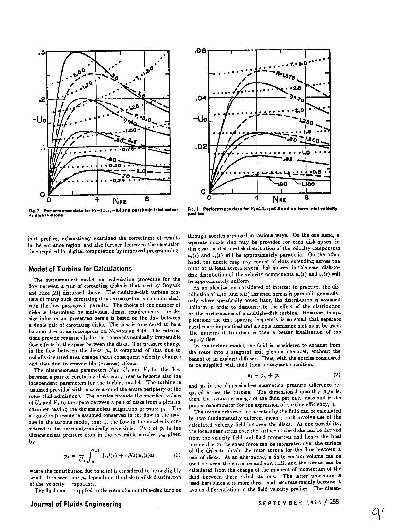
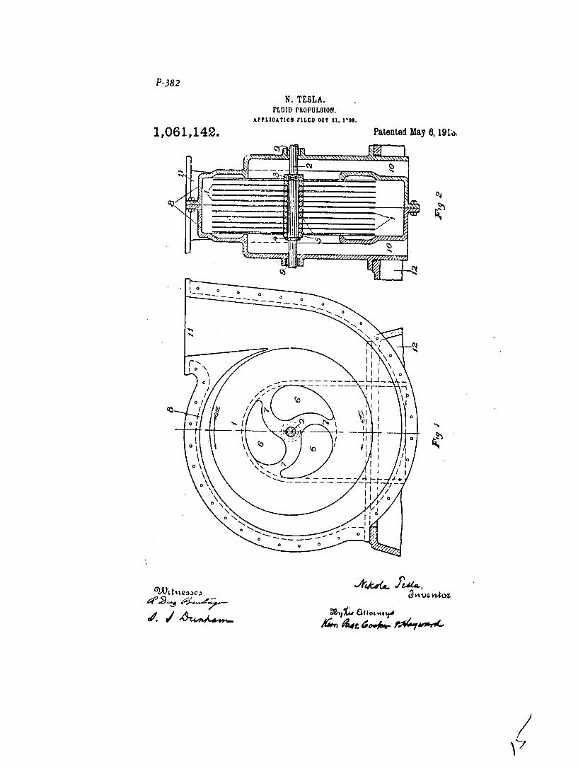

P-387
N TESLA TURBINE lgllAFLrcAT1Oll rILrEo JAW i6126 TIE1 patented May 6 1913
bull1061206
N 4D
IUDm 0 0
q0
37
77shy
f of-- -
Low er par with rotor of Teslas stea turbine
J I
7
Teslas 10000 HP steam tuirbine

77shy
f of-- -
Low er par with rotor of Teslas stea turbine
J I
7
Teslas 10000 HP steam tuirbine

J I
7
Teslas 10000 HP steam tuirbine