thayer scale - m.c.schroeder€¦ · thayer scale belt scale handbook ... a message from the...
TRANSCRIPT
THAYER SCALE BELT SCALE HANDBOOK
Application Guidelines for Installing a High Accuracy Conveyor Belt Scale
A MESSAGE FROM THE PRESIDENT OF THAYER SCALE
You need more than a “belt scale” to weigh accurately on a conveyor.
The THAYER line of conveyor weighing equipment represents the outgrowth of our company’s total commitment to provide industry with complete answers to continuous weighing problems. We emphasize the word “complete” because we firmly believe that we have been addressing ourselves to many of the problems that others continue to ignore.
Our organization and our facilities are unusually well suited to our endeavors and both represent the result of over 62 years of success in following a philosophy of focusing on the areas of business that our people know best.
Our typical equipment “package” consisting of scale suspension, load cell, belt speed transmitter, instrumentation and calibration equipment has evolved from following an integrated system approach to providing accurate and reliable weighing equipment. Many of our users express surprise when finding that our 4 and 6 idler scales require very little, if any, correction after material testing. Think of the importance of this in those installations where material testing cannot be accomplished in a practical manner.
We have prepared this material to be of use to you. We trust that you will find it both interesting and informative.
Frank S. HyerPresident
Frank S. Hyer is a graduate of Ripon College in 1956 with a B.A. degree in mathematics. He earned his B.S.M.E. at the University of Delaware in 1958 and his M.S.M.E. at the University of Wisconsin in 1968. His graduate thesis, which is entitled “A Scientific Approach to Conveyor Weighing”, has been cited on numerous occasions as a reference in technical journals dealing with the subject of conveyor weighing. He is an active member of the American Society of Mechanical Engineers and the Instrument Society of America. He has served as past director of the Process Weighing Committee of ISA, and he helped to draft the committee’s input to the National Bureau of Standards Handbook 44. In addition, he is an active patentee and contributor of technical articles in the fields of weighing and materials handling.
1
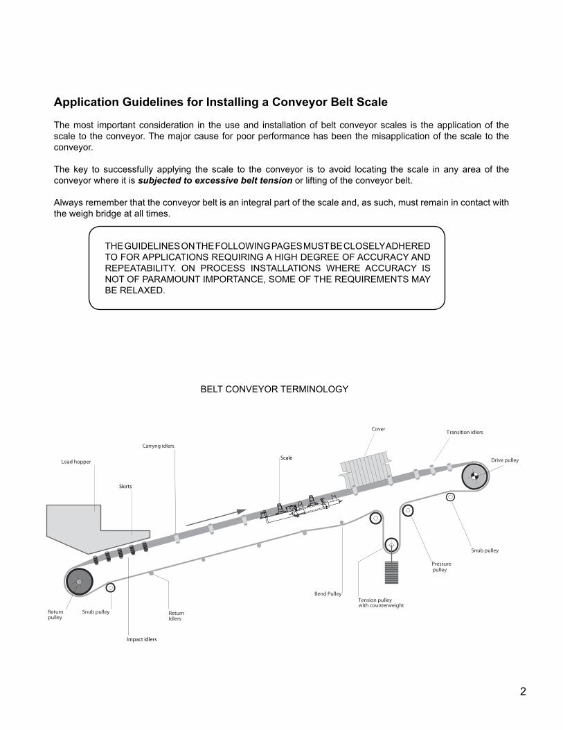
Drive pulley
Transition idlersCover
Load hopper
ReturnIdlers
Snub pulley
Carryng idlers
Returnpulley
Pressurepulley
Bend PulleyTension pulleywith counterweight
Snub pulley
Skirts
Impact idlers
Scale
Application Guidelines for Installing a Conveyor Belt Scale
The most important consideration in the use and installation of belt conveyor scales is the application of the scale to the conveyor. The major cause for poor performance has been the misapplication of the scale to the conveyor.
The key to successfully applying the scale to the conveyor is to avoid locating the scale in any area of the conveyor where it is subjected to excessive belt tension or lifting of the conveyor belt.
Always remember that the conveyor belt is an integral part of the scale and, as such, must remain in contact with the weigh bridge at all times.
THE GUIDELINES ON THE FOLLOWING PAGES MUST BE CLOSELY ADHERED TO FOR APPLICATIONS REQUIRING A HIGH DEGREE OF ACCURACY AND REPEATABILITY. ON PROCESS INSTALLATIONS WHERE ACCURACY IS NOT OF PARAMOUNT IMPORTANCE, SOME OF THE REQUIREMENTS MAY BE RELAXED.
BELT CONVEYOR TERMINOLOGY
2
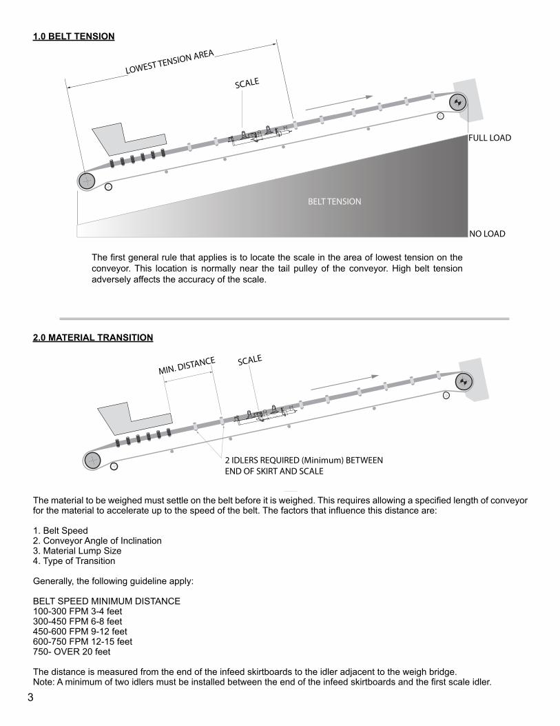
1.0 BELT TENSION
The first general rule that applies is to locate the scale in the area of lowest tension on the conveyor. This location is normally near the tail pulley of the conveyor. High belt tension adversely affects the accuracy of the scale.
LOWEST TENSION AREA
SCALE
BELT TENSION
FULL LOAD
NO LOAD
2 IDLERS REQUIRED (Minimum) BETWEEN END OF SKIRT AND SCALE
SCALEMIN. DISTANCE
The material to be weighed must settle on the belt before it is weighed. This requires allowing a specified length of conveyor for the material to accelerate up to the speed of the belt. The factors that influence this distance are:
1. Belt Speed2. Conveyor Angle of Inclination3. Material Lump Size4. Type of Transition
Generally, the following guideline apply:
BELT SPEED MINIMUM DISTANCE100-300 FPM 3-4 feet300-450 FPM 6-8 feet450-600 FPM 9-12 feet600-750 FPM 12-15 feet750- OVER 20 feet
The distance is measured from the end of the infeed skirtboards to the idler adjacent to the weigh bridge.Note: A minimum of two idlers must be installed between the end of the infeed skirtboards and the first scale idler.
2.0 MATERIAL TRANSITION
3
LOWEST TENSION AREA
SCALE
BELT TENSION
FULL LOAD
NO LOAD
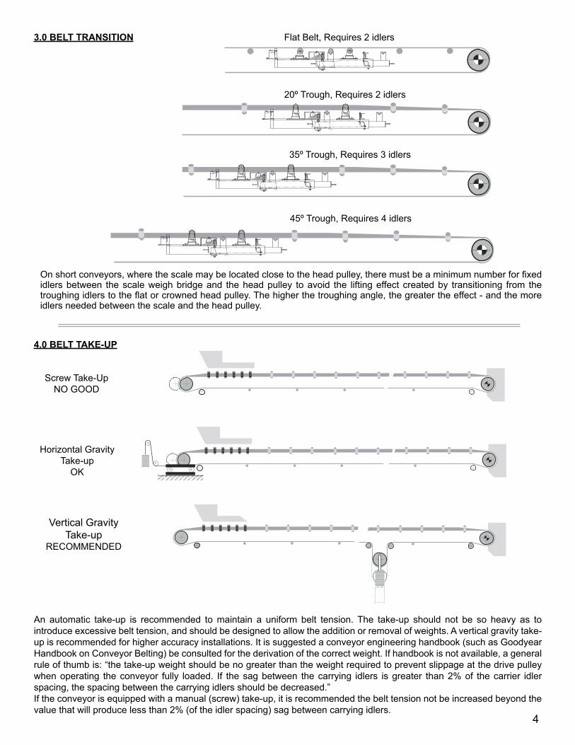
On short conveyors, where the scale may be located close to the head pulley, there must be a minimum number for fixed idlers between the scale weigh bridge and the head pulley to avoid the lifting effect created by transitioning from the troughing idlers to the flat or crowned head pulley. The higher the troughing angle, the greater the effect - and the more idlers needed between the scale and the head pulley.
3.0 BELT TRANSITION Flat Belt, Requires 2 idlers
20º Trough, Requires 2 idlers
35º Trough, Requires 3 idlers
45º Trough, Requires 4 idlers
An automatic take-up is recommended to maintain a uniform belt tension. The take-up should not be so heavy as to introduce excessive belt tension, and should be designed to allow the addition or removal of weights. A vertical gravity take-up is recommended for higher accuracy installations. It is suggested a conveyor engineering handbook (such as Goodyear Handbook on Conveyor Belting) be consulted for the derivation of the correct weight. If handbook is not available, a general rule of thumb is: “the take-up weight should be no greater than the weight required to prevent slippage at the drive pulley when operating the conveyor fully loaded. If the sag between the carrying idlers is greater than 2% of the carrier idler spacing, the spacing between the carrying idlers should be decreased.” If the conveyor is equipped with a manual (screw) take-up, it is recommended the belt tension not be increased beyond the value that will produce less than 2% (of the idler spacing) sag between carrying idlers.
4.0 BELT TAKE-UP
Screw Take-UpNO GOOD
Horizontal Gravity Take-up
OK
Vertical Gravity Take-up
RECOMMENDED
4
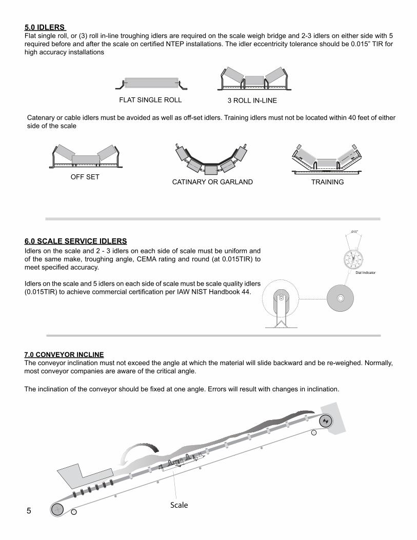
5.0 IDLERS Flat single roll, or (3) roll in-line troughing idlers are required on the scale weigh bridge and 2-3 idlers on either side with 5 required before and after the scale on certified NTEP installations. The idler eccentricity tolerance should be 0.015” TIR for high accuracy installations
Catenary or cable idlers must be avoided as well as off-set idlers. Training idlers must not be located within 40 feet of either side of the scale
FLAT SINGLE ROLL 3 ROLL IN-LINE
OFF SET CATINARY OR GARLAND TRAINING
6.0 SCALE SERVICE IDLERS
7.0 CONVEYOR INCLINEThe conveyor inclination must not exceed the angle at which the material will slide backward and be re-weighed. Normally, most conveyor companies are aware of the critical angle.
The inclination of the conveyor should be fixed at one angle. Errors will result with changes in inclination.
Scale
.015”
Idlers on the scale and 2 - 3 idlers on each side of scale must be uniform and of the same make, troughing angle, CEMA rating and round (at 0.015TIR) to meet specified accuracy.
Idlers on the scale and 5 idlers on each side of scale must be scale quality idlers (0.015TIR) to achieve commercial certification per IAW NIST Handbook 44.
Dial Indicator
5
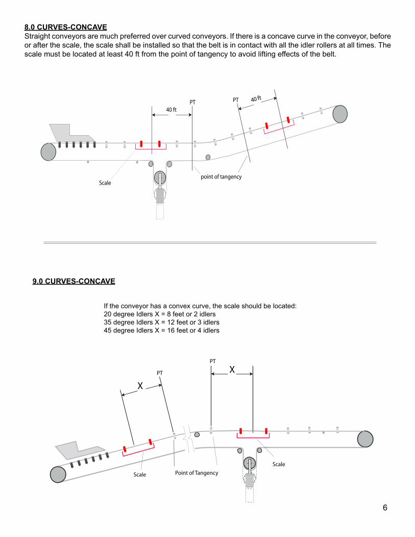
8.0 CURVES-CONCAVEStraight conveyors are much preferred over curved conveyors. If there is a concave curve in the conveyor, before or after the scale, the scale shall be installed so that the belt is in contact with all the idler rollers at all times. The scale must be located at least 40 ft from the point of tangency to avoid lifting effects of the belt.
Scale
40 ft
point of tangency
PT PT 40
ft
If the conveyor has a convex curve, the scale should be located:20 degree Idlers X = 8 feet or 2 idlers35 degree Idlers X = 12 feet or 3 idlers45 degree Idlers X = 16 feet or 4 idlers
9.0 CURVES-CONCAVE
PT
Scale
Scale
Point of Tangency
X
XPT
6
TRIPPER TRAVEL
SCALE
40 ft min.PT
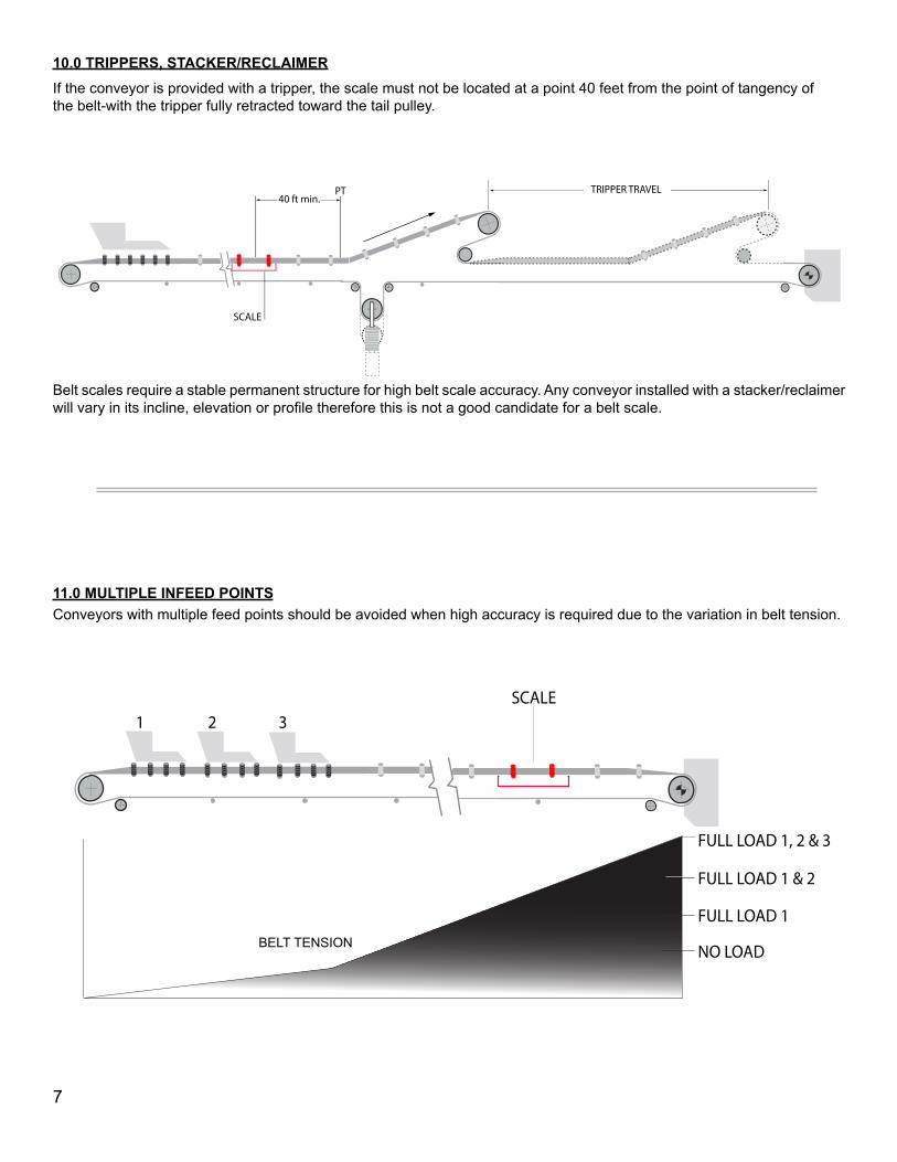
10.0 TRIPPERS, STACKER/RECLAIMERIf the conveyor is provided with a tripper, the scale must not be located at a point 40 feet from the point of tangency of the belt-with the tripper fully retracted toward the tail pulley.
SCALE1 2 3
NO LOAD
FULL LOAD 1
FULL LOAD 1 & 2
FULL LOAD 1, 2 & 3
11.0 MULTIPLE INFEED POINTSConveyors with multiple feed points should be avoided when high accuracy is required due to the variation in belt tension.
Belt scales require a stable permanent structure for high belt scale accuracy. Any conveyor installed with a stacker/reclaimer will vary in its incline, elevation or profile therefore this is not a good candidate for a belt scale.
BELT TENSION
7
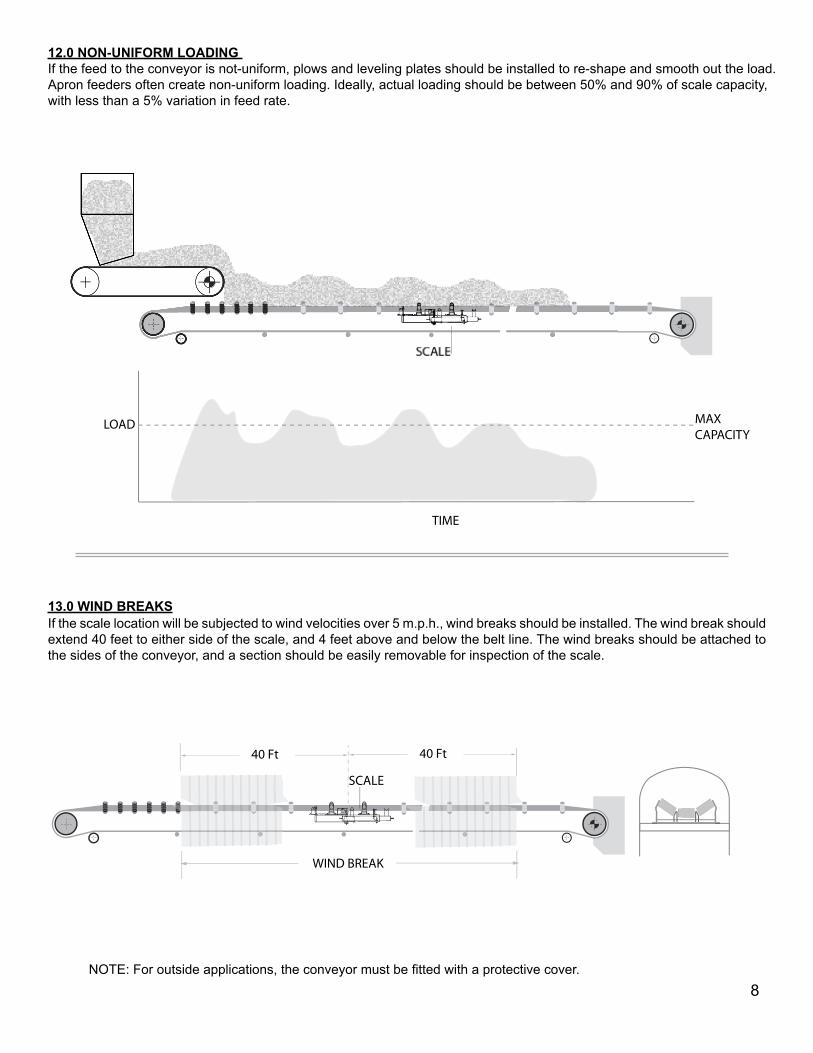
12.0 NON-UNIFORM LOADING If the feed to the conveyor is not-uniform, plows and leveling plates should be installed to re-shape and smooth out the load. Apron feeders often create non-uniform loading. Ideally, actual loading should be between 50% and 90% of scale capacity, with less than a 5% variation in feed rate.
LOAD MAX CAPACITY
TIME
If the scale location will be subjected to wind velocities over 5 m.p.h., wind breaks should be installed. The wind break should extend 40 feet to either side of the scale, and 4 feet above and below the belt line. The wind breaks should be attached to the sides of the conveyor, and a section should be easily removable for inspection of the scale.
NOTE: For outside applications, the conveyor must be fitted with a protective cover.
SCALE
40 Ft40 Ft
WIND BREAK
13.0 WIND BREAKS
8
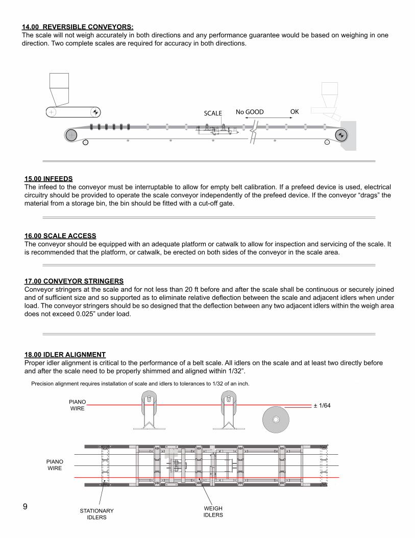
14.00 REVERSIBLE CONVEYORS:The scale will not weigh accurately in both directions and any performance guarantee would be based on weighing in one direction. Two complete scales are required for accuracy in both directions.
SCALE No GOOD OK
15.00 INFEEDSThe infeed to the conveyor must be interruptable to allow for empty belt calibration. If a prefeed device is used, electrical circuitry should be provided to operate the scale conveyor independently of the prefeed device. If the conveyor “drags” the material from a storage bin, the bin should be fitted with a cut-off gate.
16.00 SCALE ACCESSThe conveyor should be equipped with an adequate platform or catwalk to allow for inspection and servicing of the scale. It is recommended that the platform, or catwalk, be erected on both sides of the conveyor in the scale area.
17.00 CONVEYOR STRINGERSConveyor stringers at the scale and for not less than 20 ft before and after the scale shall be continuous or securely joined and of sufficient size and so supported as to eliminate relative deflection between the scale and adjacent idlers when under load. The conveyor stringers should be so designed that the deflection between any two adjacent idlers within the weigh area does not exceed 0.025” under load.
18.00 IDLER ALIGNMENTProper idler alignment is critical to the performance of a belt scale. All idlers on the scale and at least two directly before and after the scale need to be properly shimmed and aligned within 1/32”.
Precision alignment requires installation of scale and idlers to tolerances to 1/32 of an inch.
± 1/64
PIANO WIRE
PIANO WIRE
9
H35 T 2
TEMPERATURE
HUMI
DITY
˚C ˚F SCALE
CLOCK SPEED SET LIGHTNO
DISPLAY
POWER
CHART ALARM
CONFIG YES MODE
˚F
RH% 7D
1
2
3
4
THAYER SCALE- HYER INDUSTRIES, INC.
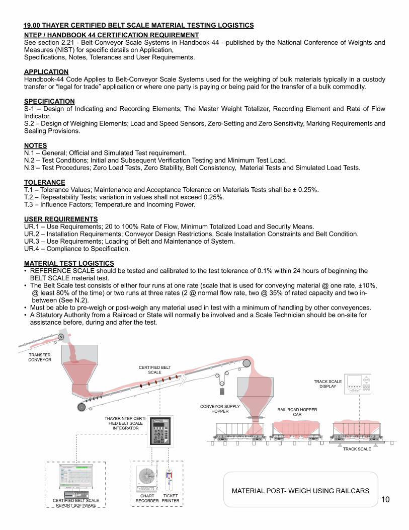
MATERIAL POST- WEIGH USING RAILCARSCERTIFIED BELT SCALE
REPORT SOFTWARE
TICKET PRINTER
CHART RECORDER
THAYER NTEP CERTI-FIED BELT SCALE
INTEGRATOR
CERTIFIED BELT SCALE
TRACK SCALE DISPLAY
TRACK SCALE
CONVEYOR SUPPLY HOPPER RAIL ROAD HOPPER
CAR
TRANSFER CONVEYOR
STATIONARY IDLERS
WEIGH IDLERS
NTEP / HANDBOOK 44 CERTIFICATION REQUIREMENTSee section 2.21 - Belt-Conveyor Scale Systems in Handbook-44 - published by the National Conference of Weights and Measures (NIST) for specific details on Application, Specifications, Notes, Tolerances and User Requirements.
APPLICATIONHandbook-44 Code Applies to Belt-Conveyor Scale Systems used for the weighing of bulk materials typically in a custody transfer or “legal for trade” application or where one party is paying or being paid for the transfer of a bulk commodity.
SPECIFICATIONS-1 – Design of Indicating and Recording Elements; The Master Weight Totalizer, Recording Element and Rate of Flow Indicator.S.2 – Design of Weighing Elements; Load and Speed Sensors, Zero-Setting and Zero Sensitivity, Marking Requirements and Sealing Provisions.
NOTESN.1 – General; Official and Simulated Test requirement.N.2 – Test Conditions; Initial and Subsequent Verification Testing and Minimum Test Load.N.3 – Test Procedures; Zero Load Tests, Zero Stability, Belt Consistency, Material Tests and Simulated Load Tests.
TOLERANCET.1 – Tolerance Values; Maintenance and Acceptance Tolerance on Materials Tests shall be ± 0.25%.T.2 – Repeatability Tests; variation in values shall not exceed 0.25%.T.3 – Influence Factors; Temperature and Incoming Power.
USER REQUIREMENTSUR.1 – Use Requirements; 20 to 100% Rate of Flow, Minimum Totalized Load and Security Means.UR.2 – Installation Requirements; Conveyor Design Restrictions, Scale Installation Constraints and Belt Condition.UR.3 – Use Requirements; Loading of Belt and Maintenance of System.UR.4 – Compliance to Specification.
MATERIAL TEST LOGISTICSREFERENCE SCALE should be tested and calibrated to the test tolerance of 0.1% within 24 hours of beginning the BELT SCALE material test. The Belt Scale test consists of either four runs at one rate (scale that is used for conveying material @ one rate, ±10%, @ least 80% of the time) or two runs at three rates (2 @ normal flow rate, two @ 35% of rated capacity and two in- between (See N.2). Must be able to pre-weigh or post-weigh any material used in test with a minimum of handling by other conveyences.A Statutory Authority from a Railroad or State will normally be involved and a Scale Technician should be on-site for assistance before, during and after the test.
•
•
••
H35 T 2
TEMPERATURE
HUMI
DITY
˚C ˚F SCALE
CLOCK SPEED SET LIGHTNO
DISPLAY
POWER
CHART ALARM
CONFIG YES MODE
˚F
RH% 7D
1
2
3
4
THAYER SCALE- HYER INDUSTRIES, INC.
MATERIAL POST- WEIGH USING RAILCARSCERTIFIED BELT SCALE
REPORT SOFTWARE
TICKET PRINTER
CHART RECORDER
THAYER NTEP CERTI-FIED BELT SCALE
INTEGRATOR
CERTIFIED BELT SCALE
TRACK SCALE DISPLAY
TRACK SCALE
CONVEYOR SUPPLY HOPPER RAIL ROAD HOPPER
CAR
TRANSFER CONVEYOR
19.00 THAYER CERTIFIED BELT SCALE MATERIAL TESTING LOGISTICS
10
H35 T 2
TEMPERATURE
HUMI
DITY
˚C ˚F SCALE
CLOCK SPEED SET LIGHTNO
DISPLAY
POWER
CHART ALARM
CONFIG YES MODE
˚F
RH% 7D
1
2
3
4
THAYER SCALE- HYER INDUSTRIES, INC.
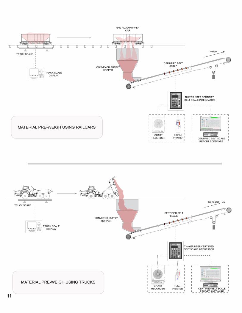
MATERIAL PRE-WEIGH USING TRUCKS
TRUCK SCALE DISPLAY
TRUCK SCALE
CONVEYOR SUPPLY HOPPER
TO PLANT
CERTIFIED BELT SCALE
THAYER NTEP CERTIFIED BELT SCALE INTEGRATOR
CHART RECORDER
TICKET PRINTER CERTIFIED BELT SCALE
REPORT SOFTWARE
To Plant
H35 T 2
TEMPERATURE
HUMI
DITY
˚C ˚F SCALE
CLOCK SPEED SET LIGHTNO
DISPLAY
POWER
CHART ALARM
CONFIG YES MODE
˚F
RH% 7D
1
2
3
4
THAYER SCALE- HYER INDUSTRIES, INC.
MATERIAL PRE-WEIGH USING RAILCARS
THAYER NTEP CERTIFIED BELT SCALE INTEGRATOR
CERTIFIED BELT SCALE REPORT SOFTWARE
TICKET PRINTER
CHART RECORDER
CERTIFIED BELT SCALECONVEYOR SUPPLY
HOPPERTRACK SCALE
DISPLAY
TRACK SCALE
RAIL ROAD HOPPER CAR
11
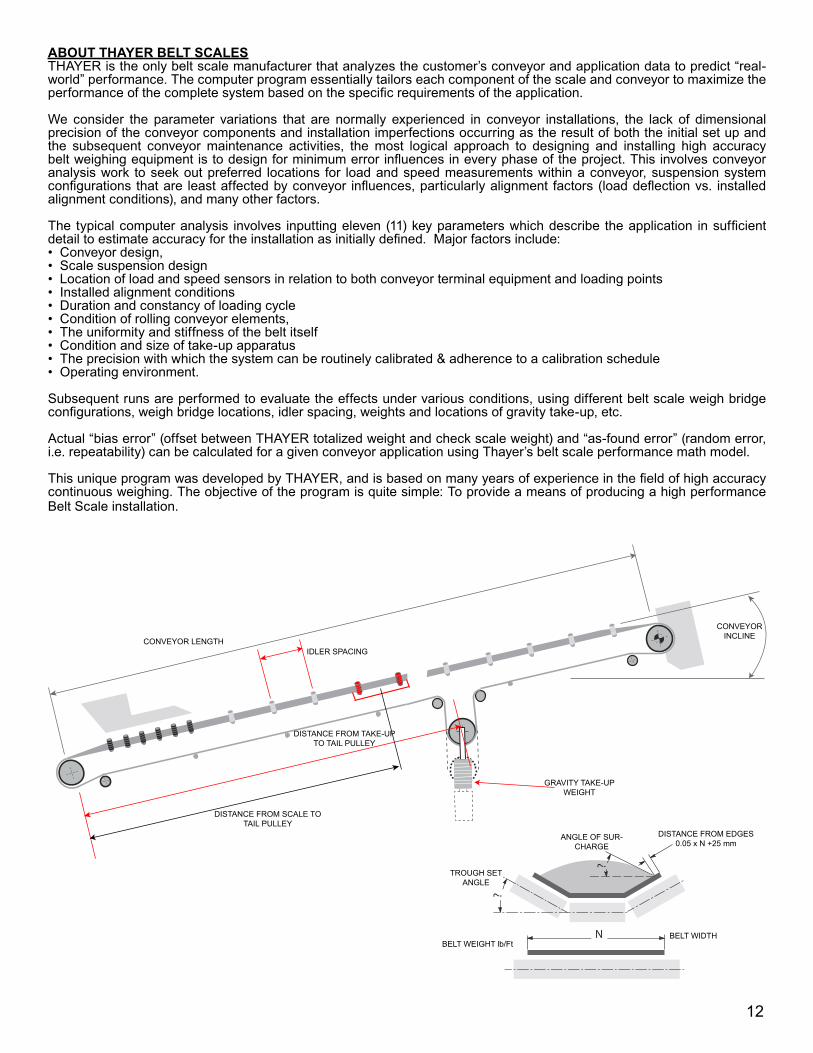
ABOUT THAYER BELT SCALESTHAYER is the only belt scale manufacturer that analyzes the customer’s conveyor and application data to predict “real-world” performance. The computer program essentially tailors each component of the scale and conveyor to maximize the performance of the complete system based on the specific requirements of the application.
We consider the parameter variations that are normally experienced in conveyor installations, the lack of dimensional precision of the conveyor components and installation imperfections occurring as the result of both the initial set up and the subsequent conveyor maintenance activities, the most logical approach to designing and installing high accuracy belt weighing equipment is to design for minimum error influences in every phase of the project. This involves conveyor analysis work to seek out preferred locations for load and speed measurements within a conveyor, suspension system configurations that are least affected by conveyor influences, particularly alignment factors (load deflection vs. installed alignment conditions), and many other factors.
The typical computer analysis involves inputting eleven (11) key parameters which describe the application in sufficient detail to estimate accuracy for the installation as initially defined. Major factors include:
Conveyor design, Scale suspension design Location of load and speed sensors in relation to both conveyor terminal equipment and loading pointsInstalled alignment conditionsDuration and constancy of loading cycleCondition of rolling conveyor elements, The uniformity and stiffness of the belt itself Condition and size of take-up apparatusThe precision with which the system can be routinely calibrated & adherence to a calibration schedule Operating environment.
Subsequent runs are performed to evaluate the effects under various conditions, using different belt scale weigh bridge configurations, weigh bridge locations, idler spacing, weights and locations of gravity take-up, etc.
Actual “bias error” (offset between THAYER totalized weight and check scale weight) and “as-found error” (random error, i.e. repeatability) can be calculated for a given conveyor application using Thayer’s belt scale performance math model.
This unique program was developed by THAYER, and is based on many years of experience in the field of high accuracy continuous weighing. The objective of the program is quite simple: To provide a means of producing a high performance Belt Scale installation.
••••••••••
IDLER SPACINGCONVEYOR LENGTH
CONVEYOR INCLINE
GRAVITY TAKE-UP WEIGHT
DISTANCE FROM SCALE TO TAIL PULLEY
DISTANCE FROM TAKE-UP TO TAIL PULLEY
N
TROUGH SET ANGLE
ANGLE OF SUR-CHARGE
DISTANCE FROM EDGES 0.05 x N +25 mm
BELT WIDTHBELT WEIGHT lb/Ft
12
THAYER MODEL No.
No. of Weigh Idlers
Stringer depth
(inches)
Belt Width
(inches
Idler Spacing (inches Idler Loading Accuracy (%)
FULL SCALEAccuracy (%)
3:1 Load
GENERAL PURPOSE1RF-3A-SG 1 N/A 18” - 30” 30”- 60” 300 lb max 1 21RF-4A-SG 1 N/A 36” - 48” 30”- 60” 300 lb max 1 2
1RF-4A 1 4 14” - 48” 30”- 60” 7.2 - 300 1 22RF-4A 2 4 14” - 48” 30”- 60” 5.4 - 300 ±1/4 ±1/22RF-6A 2 6 24” - 60” 30”- 60” 12 - 800 ±1/4 ±1/23RF-6A 3 6 24” - 60” 30”- 60” 8.8 - 600 ±1/4 ±1/23RF-8A 3 8 30” - 72” 30”- 60” 8.8 - 1600 ±1/4 ±1/2
4RF-6AR 4 6 24” - 60” 30”- 60” 6 - 525 ±1/8 ±1/4RFS 6 6 24” - 60’ 30”- 60” 4.3 - 400 ±1/10 ±1/8
6RF-8AR 6 8 30” - 72” 30”- 60” 4.3 - 1200 ±1/10 ±1/8
LIGHT LOADING SCALES2LLRF-4A 2 4 14” - 48” 42”- 60” 5.4 - 300 ±1/4 ±1/22RF-6ALA 2 6 24” - 72” 42”- 60” 4.2 - 800 ±1/4 ±1/2
3RF-6ARLA 3 6 24” - 72” 42”- 60” 3.2 - 600 ±1/4 ±1/24RF-6ARLA 4 6 24” - 60” 42”- 60” 2.1 - 525 ±1/8 ±1/46RF-6ARLA 6 6 24” - 60” 42”- 60” 1.6 - 400 ±1/10 ±1/8
NTEP CERTIFIED SCALESNAR-4 4 4 24” - 60” 36” - 60” 34 - 525 ±1/10 ±1/8
NAR-6 (6” stringer) 6 6 24” - 60” 36” - 60” 34 - 400 ±1/10 ±1/8NAR-6 (8” stringer) 6 8 30” - 96” 36” - 60” 34 -1200 ±1/10 ±1/8NAR-8 (8” stringer) 8 8 30” - 96” 36” - 60” 34 -1200 ±1/10 ±1/8
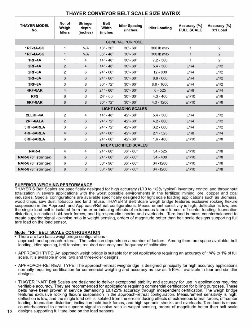
THAYER CONVEYOR BELT SCALE SIZE MATRIX
SUPERIOR WEIGHING PERFORMANCETHAYER’S Belt Scales are specifically designed for high accuracy (1/10 to 1/2% typical) inventory control and throughput totalization in severe applications with the worst possible environments in the fertilizer, mining, ore, copper and coal industries. Special configurations are available specifically designed for light scale loading applications such as Biomass, wood chips, saw dust, tobacco and land refuse. THAYER’S Belt Scale weigh bridge features exclusive rocking flexure suspension in the Approach and Approach/Retreat configurations. Measurement sensitivity is high, deflection is low, and the single load cell is isolated from the error-inducing effects of extraneous lateral forces, off-center loading, foundation distortion, inclination hold-back forces, and high sporadic shocks and overloads. Tare load is mass counterbalanced to create superior signal -to-noise ratio in weight sensing, orders of magnitude better than belt scale designs supporting full tare load on the load sensor.
Model “RF” BELT SCALE CONFIGURATIONThere are two basic weighbridge configurations - approach and approach-retreat. The selection depends on a number of factors. Among them are space available, belt loading, idler spacing, belt tension, required accuracy and frequency of calibration.
APPROACH TYPE: An approach weigh bridge is suitable for most applications requiring an accuracy of 1/4% to 1% of full scale. It is available in one, two and three-idler designs.
APPROACH-RETREAT TYPE: The approach-retreat weighbridge is designed principally for high accuracy applications normally requiring certification for commercial weighing and accuracy as low as 1/10%... available in four and six idler designs.
THAYER “NAR” Belt Scales are designed to deliver exceptional stability and accuracy for use in applications requiring verifiable accuracy. They are recommended for applications requiring commercial certification for billing purposes. These belts have been proven in service demanding ±0.125% accuracy through independent certification. The weigh bridge features exclusive rocking flexure suspension in the approach-retreat configuration. Measurement sensitivity is high, deflection is low, and the single load cell is isolated from the error-inducing effects of extraneous lateral forces, off-center loading, foundation distortion, inclination hold-back forces, and high sporadic shocks and overloads. Tare load is mass-counterbalanced to create superior signal to noise ratio in weight sensing, orders of magnitude better than belt scale designs supporting full tare load on the load sensors.
•
•
•
•
13
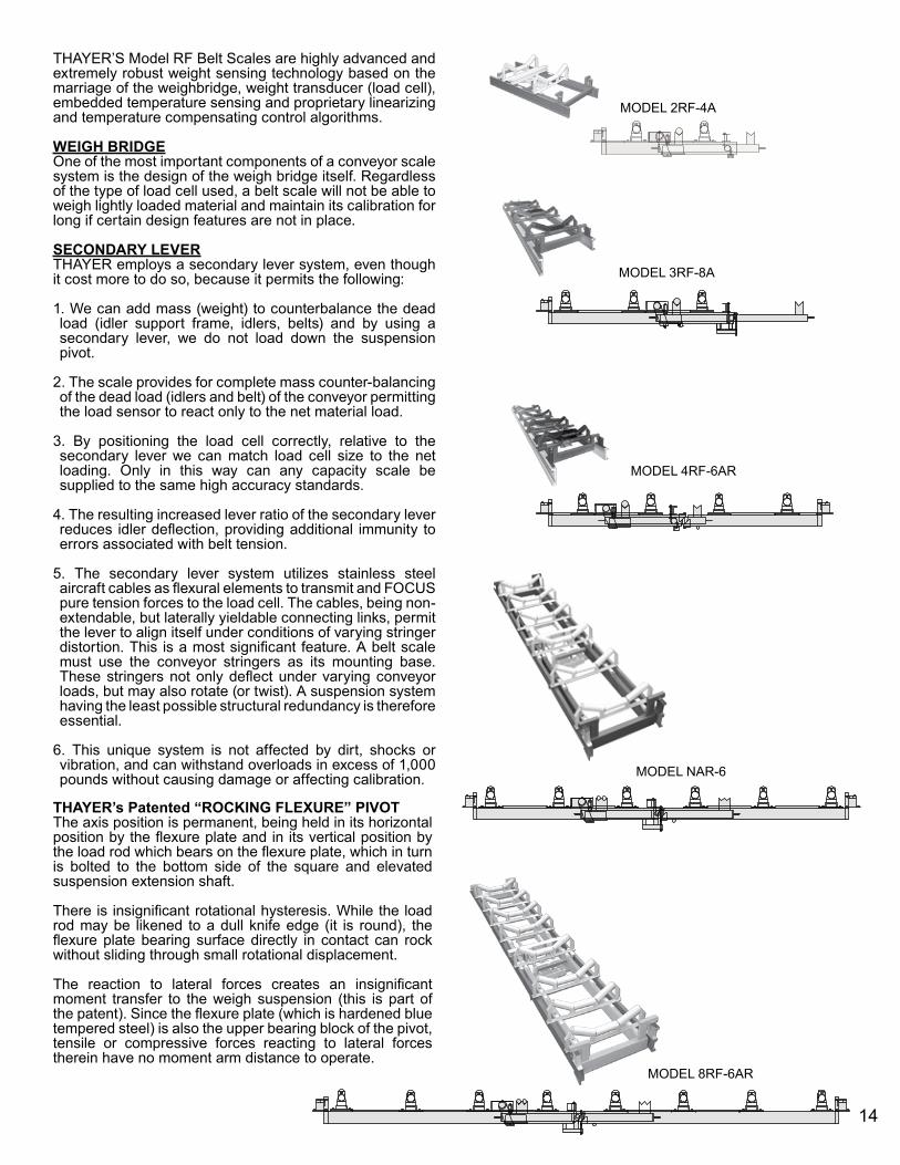
MODEL 2RF-4A
MODEL 3RF-8A
MODEL 4RF-6AR
MODEL NAR-6
MODEL 8RF-6AR
THAYER’S Model RF Belt Scales are highly advanced and extremely robust weight sensing technology based on the marriage of the weighbridge, weight transducer (load cell), embedded temperature sensing and proprietary linearizing and temperature compensating control algorithms.
WEIGH BRIDGEOne of the most important components of a conveyor scale system is the design of the weigh bridge itself. Regardless of the type of load cell used, a belt scale will not be able to weigh lightly loaded material and maintain its calibration for long if certain design features are not in place.
SECONDARY LEVERTHAYER employs a secondary lever system, even though it cost more to do so, because it permits the following:
1. We can add mass (weight) to counterbalance the dead load (idler support frame, idlers, belts) and by using a secondary lever, we do not load down the suspension pivot.
2. The scale provides for complete mass counter-balancing of the dead load (idlers and belt) of the conveyor permitting the load sensor to react only to the net material load.
3. By positioning the load cell correctly, relative to the secondary lever we can match load cell size to the net loading. Only in this way can any capacity scale be supplied to the same high accuracy standards.
4. The resulting increased lever ratio of the secondary lever reduces idler deflection, providing additional immunity to errors associated with belt tension.
5. The secondary lever system utilizes stainless steel aircraft cables as flexural elements to transmit and FOCUS pure tension forces to the load cell. The cables, being non-extendable, but laterally yieldable connecting links, permit the lever to align itself under conditions of varying stringer distortion. This is a most significant feature. A belt scale must use the conveyor stringers as its mounting base. These stringers not only deflect under varying conveyor loads, but may also rotate (or twist). A suspension system having the least possible structural redundancy is therefore essential.
6. This unique system is not affected by dirt, shocks or vibration, and can withstand overloads in excess of 1,000 pounds without causing damage or affecting calibration.
THAYER’s Patented “ROCKING FLEXURE” PIVOTThe axis position is permanent, being held in its horizontal position by the flexure plate and in its vertical position by the load rod which bears on the flexure plate, which in turn is bolted to the bottom side of the square and elevated suspension extension shaft.
There is insignificant rotational hysteresis. While the load rod may be likened to a dull knife edge (it is round), the flexure plate bearing surface directly in contact can rock without sliding through small rotational displacement.
The reaction to lateral forces creates an insignificant moment transfer to the weigh suspension (this is part of the patent). Since the flexure plate (which is hardened blue tempered steel) is also the upper bearing block of the pivot, tensile or compressive forces reacting to lateral forces therein have no moment arm distance to operate.
14
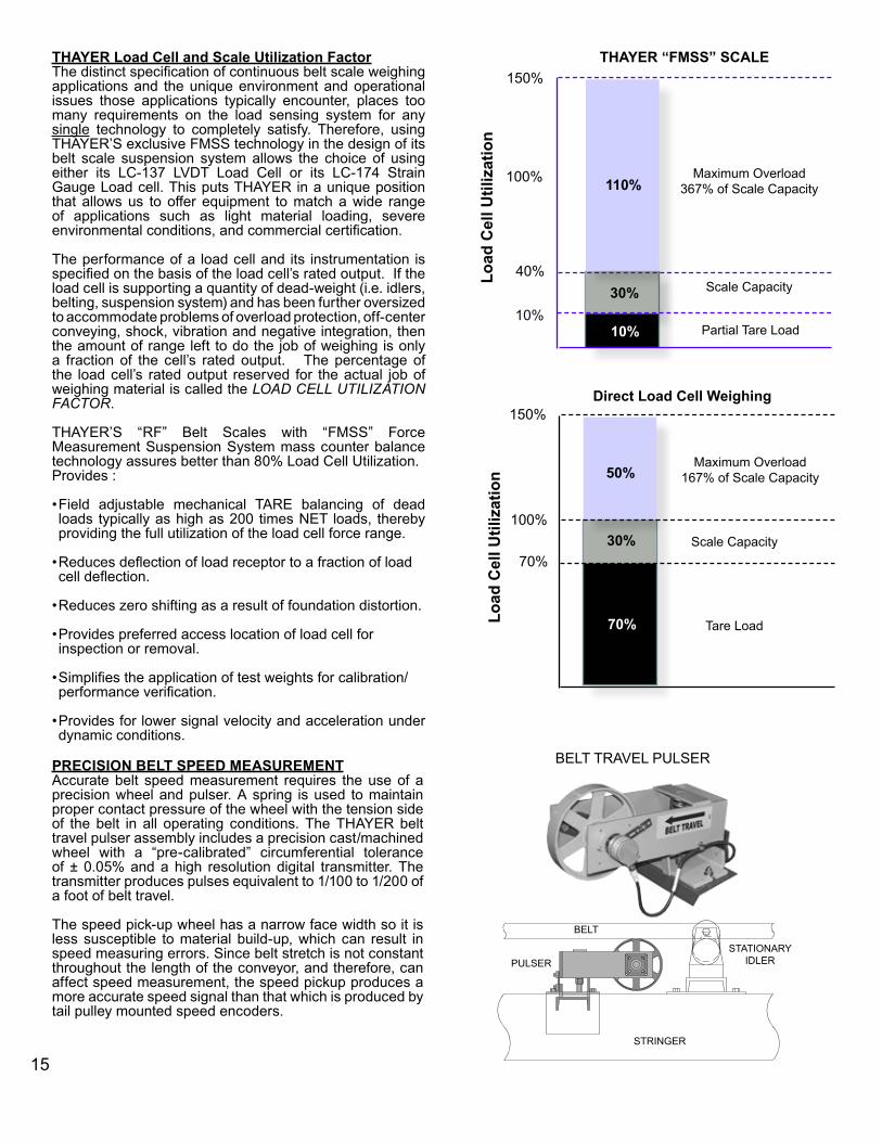
THAYER Load Cell and Scale Utilization FactorThe distinct specification of continuous belt scale weighing applications and the unique environment and operational issues those applications typically encounter, places too many requirements on the load sensing system for any single technology to completely satisfy. Therefore, using THAYER’S exclusive FMSS technology in the design of its belt scale suspension system allows the choice of using either its LC-137 LVDT Load Cell or its LC-174 Strain Gauge Load cell. This puts THAYER in a unique position that allows us to offer equipment to match a wide range of applications such as light material loading, severe environmental conditions, and commercial certification.
The performance of a load cell and its instrumentation is specified on the basis of the load cell’s rated output. If the load cell is supporting a quantity of dead-weight (i.e. idlers, belting, suspension system) and has been further oversized to accommodate problems of overload protection, off-center conveying, shock, vibration and negative integration, then the amount of range left to do the job of weighing is only a fraction of the cell’s rated output. The percentage of the load cell’s rated output reserved for the actual job of weighing material is called the LOAD CELL UTILIZATION FACTOR.
THAYER’S “RF” Belt Scales with “FMSS” Force Measurement Suspension System mass counter balance technology assures better than 80% Load Cell Utilization. Provides :
• Field adjustable mechanical TARE balancing of dead loads typically as high as 200 times NET loads, thereby providing the full utilization of the load cell force range.
• Reduces deflection of load receptor to a fraction of load cell deflection.
• Reduces zero shifting as a result of foundation distortion.
• Provides preferred access location of load cell for inspection or removal.
• Simplifies the application of test weights for calibration/performance verification.
• Provides for lower signal velocity and acceleration under dynamic conditions.
PRECISION BELT SPEED MEASUREMENTAccurate belt speed measurement requires the use of a precision wheel and pulser. A spring is used to maintain proper contact pressure of the wheel with the tension side of the belt in all operating conditions. The THAYER belt travel pulser assembly includes a precision cast/machined wheel with a “pre-calibrated” circumferential tolerance of ± 0.05% and a high resolution digital transmitter. The transmitter produces pulses equivalent to 1/100 to 1/200 of a foot of belt travel.
The speed pick-up wheel has a narrow face width so it is less susceptible to material build-up, which can result in speed measuring errors. Since belt stretch is not constant throughout the length of the conveyor, and therefore, can affect speed measurement, the speed pickup produces a more accurate speed signal than that which is produced by tail pulley mounted speed encoders.
30%
10%
110%
10%
THAYER “FMSS” SCALE150%
100%
40%Load
Cel
l Util
izat
ion
Partial Tare Load
Scale Capacity
Maximum Overload367% of Scale Capacity
BELT TRAVEL PULSER
150%
100%
70%
70%
50%
Direct Load Cell Weighing
Load
Cel
l Util
izat
ion
30%
Maximum Overload167% of Scale Capacity
Scale Capacity
Tare Load
15
BELT
STRINGER
PULSERSTATIONARY
IDLER
16
CALIBRATIONA belt scale should be thought of as a precision instrument and its performance should be quickly and easily checked. Accuracy and the method and frequency of calibration are directly related. It is a well known fact that the only positive way of verifying scale accuracy is to conduct a material test using a static scale to check the weight of material passed over the scale. The results of the material test are used to factor the simulated test device which is either a test chain or calibrating weight.
Thayer Scale is the only manufacturer that can provide an accurate reliable calibration using a calibration weight instead of test chains for all scale capacities. As a result other manufacturers have had to resort to dummy signals which (while providing a stable signal to calibrate the integrator) result in very large scale calibration errors and a false sense of security due to the fact that the scale’s mechanical components are not exercised during the span portion of the calibration.
Thayer Scale developed and patented the first automatic calibration system in 1971. Although there have been attempts to develop non-infringing systems none of them have achieved the simplicity or accuracy of the Thayer method.
TEST WEIGHT CALIBRATIONPast experience with test weights has been generally poor because none of the scale manufacturers were able to correlate the value of weight with respect to the pounds per foot loading it represented on the conveyor belt. Consequently all sorts of false theories were generated about test chains best simulating actual material on the conveyor belt.
Another problem relating to test weights is that on large capacity scales such as those employing a full floating weigh bridge, it is virtually impossible for most scale manufacturers to use test weights because the size of the weight required prohibits their use.
Thayer Scale pioneered the successful use of the test weight calibration technique by a careful and thorough analysis of the factors that relate to the methods of simulated testing. Additionally, such large weights pose a potential safety problem for plant personnel.
DEAD WEIGHT TESTThe only exact method of determining the value of the test weight is by dead load testing the scale. This is done by completely assembling the weighbridge and scale and placing test weights on the idler mounting pads to duplicate the idler belt and material weight. The counterbalance weights are than adjusted to empty balance the scale. After the scale has been calibrated and zeroed to the dead weight, the value of the calibration weight is determined by the substitution method. Very few manufacturers dead load test the complete scale. Consequently, it is difficult to predict how large an error may exist between actual material weight and the simulated load. The use of a test weight is the only assurance the user has against gross weighing errors.
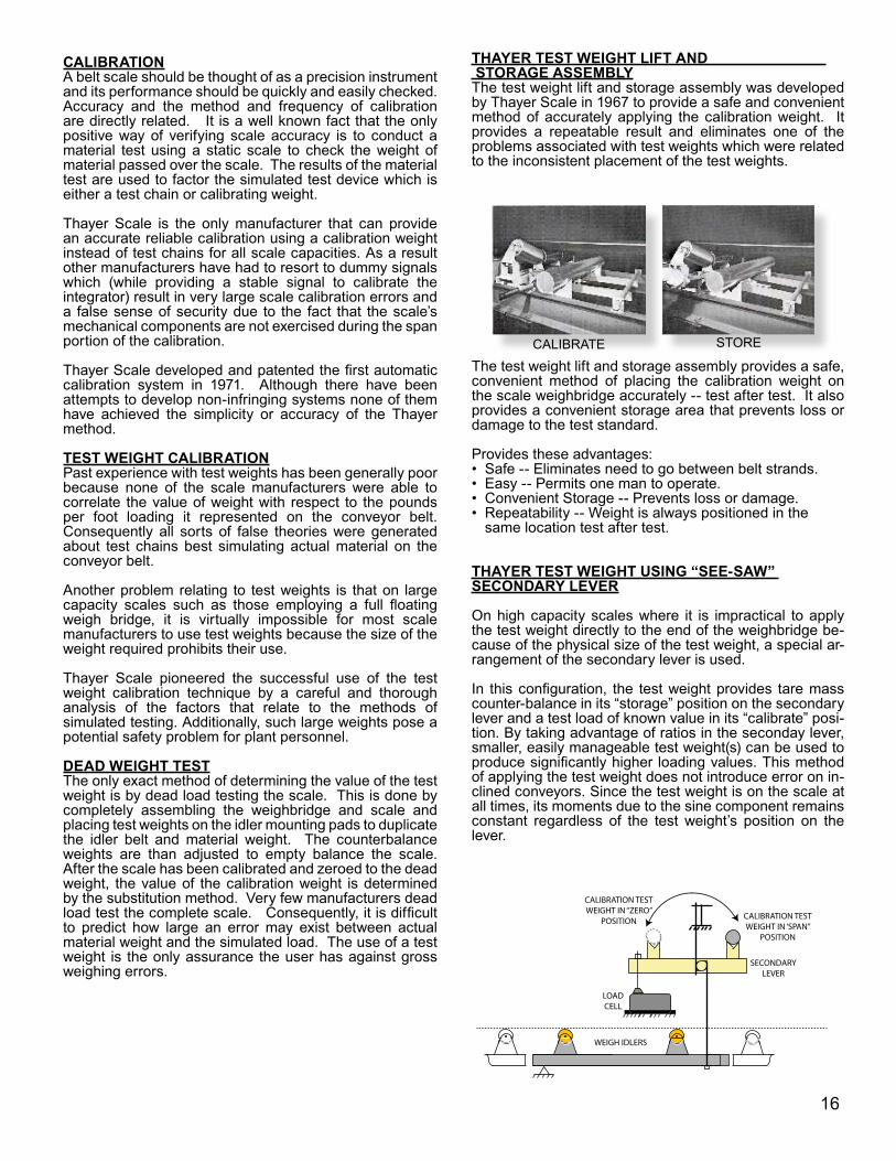
THAYER TEST WEIGHT LIFT AND STORAGE ASSEMBLYThe test weight lift and storage assembly was developed by Thayer Scale in 1967 to provide a safe and convenient method of accurately applying the calibration weight. It provides a repeatable result and eliminates one of the problems associated with test weights which were related to the inconsistent placement of the test weights.
The test weight lift and storage assembly provides a safe, convenient method of placing the calibration weight on the scale weighbridge accurately -- test after test. It also provides a convenient storage area that prevents loss or damage to the test standard.
Provides these advantages:Safe -- Eliminates need to go between belt strands.Easy -- Permits one man to operate.Convenient Storage -- Prevents loss or damage.Repeatability -- Weight is always positioned in the same location test after test.
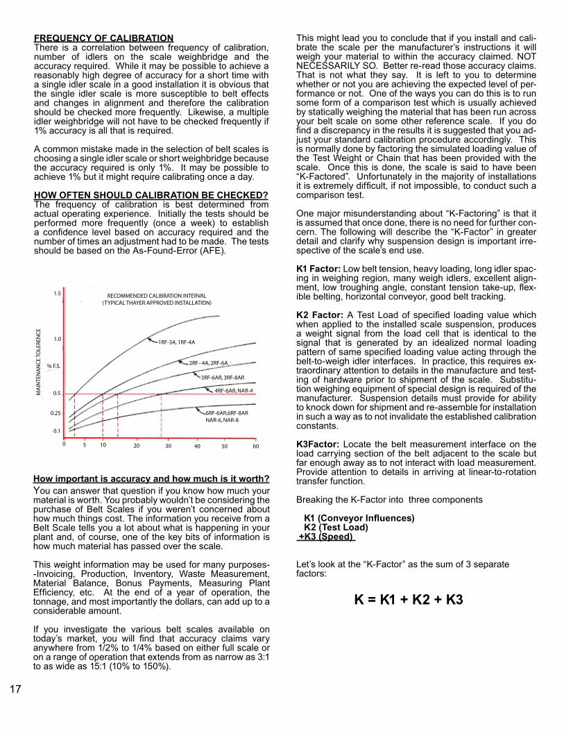
THAYER TEST WEIGHT USING “SEE-SAW” SECONDARY LEVER
On high capacity scales where it is impractical to apply the test weight directly to the end of the weighbridge be-cause of the physical size of the test weight, a special ar-rangement of the secondary lever is used.
In this configuration, the test weight provides tare mass counter-balance in its “storage” position on the secondary lever and a test load of known value in its “calibrate” posi-tion. By taking advantage of ratios in the seconday lever, smaller, easily manageable test weight(s) can be used to produce significantly higher loading values. This method of applying the test weight does not introduce error on in-clined conveyors. Since the test weight is on the scale at all times, its moments due to the sine component remains constant regardless of the test weight’s position on the lever.
••••
CALIBRATE STORE
CALIBRATION TEST WEIGHT IN “ZERO”
POSITIONCALIBRATION TEST WEIGHT IN ‘SPAN”
POSITION
SECONDARY LEVER
LOAD CELL
WEIGH IDLERS
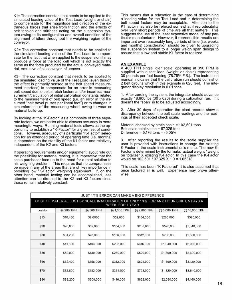
6RF-6AR,6RF-8ARNAR-6, NAR-8
4RF-6AR, NAR-4
3RF-6AR, 3RF-8AR
2RF--4A, 2RF-6A
1RF-3A, 1RF-4A
RECOMMENDED CALIBRATION INTERVAL(TYPICAL THAYER APPROVED INSTALLATION)
MA
INTE
NA
NC
E TO
LERE
NC
E
0 5 10 20 30 40 50 60
0.1
0.25
0.5
% F.S.
1.0
1.5
FREQUENCY OF CALIBRATIONThere is a correlation between frequency of calibration, number of idlers on the scale weighbridge and the accuracy required. While it may be possible to achieve a reasonably high degree of accuracy for a short time with a single idler scale in a good installation it is obvious that the single idler scale is more susceptible to belt effects and changes in alignment and therefore the calibration should be checked more frequently. Likewise, a multiple idler weighbridge will not have to be checked frequently if 1% accuracy is all that is required.
A common mistake made in the selection of belt scales is choosing a single idler scale or short weighbridge because the accuracy required is only 1%. It may be possible to achieve 1% but it might require calibrating once a day.
HOW OFTEN SHOULD CALIBRATION BE CHECKED?The frequency of calibration is best determined from actual operating experience. Initially the tests should be performed more frequently (once a week) to establish a confidence level based on accuracy required and the number of times an adjustment had to be made. The tests should be based on the As-Found-Error (AFE).
How important is accuracy and how much is it worth?You can answer that question if you know how much your material is worth. You probably wouldn’t be considering the purchase of Belt Scales if you weren’t concerned about how much things cost. The information you receive from a Belt Scale tells you a lot about what is happening in your plant and, of course, one of the key bits of information is how much material has passed over the scale.
This weight information may be used for many purposes--Invoicing, Production, Inventory, Waste Measurement, Material Balance, Bonus Payments, Measuring Plant Efficiency, etc. At the end of a year of operation, the tonnage, and most importantly the dollars, can add up to a considerable amount.
If you investigate the various belt scales available on today’s market, you will find that accuracy claims vary anywhere from 1/2% to 1/4% based on either full scale or on a range of operation that extends from as narrow as 3:1 to as wide as 15:1 (10% to 150%).
This might lead you to conclude that if you install and cali-brate the scale per the manufacturer’s instructions it will weigh your material to within the accuracy claimed. NOT NECESSARILY SO. Better re-read those accuracy claims. That is not what they say. It is left to you to determine whether or not you are achieving the expected level of per-formance or not. One of the ways you can do this is to run some form of a comparison test which is usually achieved by statically weighing the material that has been run across your belt scale on some other reference scale. If you do find a discrepancy in the results it is suggested that you ad-just your standard calibration procedure accordingly. This is normally done by factoring the simulated loading value of the Test Weight or Chain that has been provided with the scale. Once this is done, the scale is said to have been “K-Factored”. Unfortunately in the majority of installations it is extremely difficult, if not impossible, to conduct such a comparison test.
One major misunderstanding about “K-Factoring” is that it is assumed that once done, there is no need for further con-cern. The following will describe the “K-Factor” in greater detail and clarify why suspension design is important irre-spective of the scale’s end use.
K1 Factor: Low belt tension, heavy loading, long idler spac-ing in weighing region, many weigh idlers, excellent align-ment, low troughing angle, constant tension take-up, flex-ible belting, horizontal conveyor, good belt tracking.
K2 Factor: A Test Load of specified loading value which when applied to the installed scale suspension, produces a weight signal from the load cell that is identical to the signal that is generated by an idealized normal loading pattern of same specified loading value acting through the belt-to-weigh idler interfaces. In practice, this requires ex-traordinary attention to details in the manufacture and test-ing of hardware prior to shipment of the scale. Substitu-tion weighing equipment of special design is required of the manufacturer. Suspension details must provide for ability to knock down for shipment and re-assemble for installation in such a way as to not invalidate the established calibration constants.
K3Factor: Locate the belt measurement interface on the load carrying section of the belt adjacent to the scale but far enough away as to not interact with load measurement. Provide attention to details in arriving at linear-to-rotation transfer function.
Breaking the K-Factor into three components
K1 (Conveyor Influences) K2 (Test Load) +K3 (Speed)
Let’s look at the “K-Factor” as the sum of 3 separate factors:
K = K1 + K2 + K3
17
JUST 1/4% ERROR CAN MAKE A BIG DIFFERENCECOST OF MATERIAL LOST BY SCALE INACCURACIES OF ONLY 1/4% FOR AN 8 HOUR SHIFT, 5 DAYS A
WEEK, FOR 1 YEARcost/ton @ 200 TPH @ 500 TPH @ 1,000 TPH @ 2,000 TPH @ 5,000 TPH @ 10,000 TPH
$10 $10,400 $2,6000 $52,000 $104,000 $260,000 $520,000
$20 $20,800 $52,000 $104,000 $208,000 $520,000 $1,040,000
$30 $31,200 $78,000 $156,000 $312,000 $780,000 $1,560,000
$40 $41,600 $104,000 $208,000 $416,000 $1,040,000 $2,080,000
$50 $52,000 $130,000 $260,000 $520,000 $1,300,000 $2,600,000
$60 $62,400 $156,000 $312,000 $624,000 $1,560,000 $3,120,000
$70 $72,800 $182,000 $364,000 $728,000 $1,820,000 $3,640,000
$80 $83,200 $208,000 $416,000 $832,000 $2,080,000 $4,160,000
K1= The correction constant that needs to be applied to the simulated loading value of the Test Load (weight or chain) to compensate for the magnitude and direction of the ex-traneous forces that arise from friction and the effects of belt tension and stiffness acting on the suspension sys-tem owing to its configuration and overall condition of the alignment of idlers throughout the weighing region of the conveyor.
K2= The correction constant that needs to be applied to the simulated loading value of the Test Load to compen-sate for the fact that when applied to the suspension it may produce a force at the load cell which is not exactly the same as the force produced by the actual conveyed mate-rial, exclusive of all conveyer influences. K3= The correction constant that needs to be applied to the simulated loading value of the Test Load (even though the effect is primarily sensed at the belt speed measure-ment interface) to compensate for an error in measuring belt speed due to belt stretch factors and/or incorrect mea-surement/calculation of initial calibration constants related to the measurement of belt speed (i.e. an error in the as-sumed “belt travel pulses per lineal foot”) or to changes in circumference of the measuring wheel owing to wear or material build-up.
By looking at the “K-Factor” as a composite of three sepa-rate factors, we are better able to discuss accuracy in more meaningful ways. Running material tests allows us the op-portunity to establish a “K-Factor” for a given set of condi-tions. However, adequacy of a particular “K-Factor” selec-tion for an extended period of operating time (i.e. months) is dependent on the stability of the K1 factor and relatively independent of the K2 and K3 factors.
If operating requirements and/or equipment layout rule out the possibility for material testing, It is imperative that the scale purchaser face up to the need for a total solution to his weighing problem. This requires that no compromises be made in any of the areas that are of key importance in providing low “K-Factor” weighing equipment. If, on the other hand, material testing can be accomplished, less attention can be directed to the K2 and K3 factors since these remain relatively constant.
This means that a relaxation in the care of determining a loading value for the Test Load and in determining the belt speed factors may be acceptable. Attention to the K1 factor may also be relaxed somewhat if reproducibility over very short periods of time are all that matters. This suggests the use of the least expensive model of any par-ticular manufacturer. However, if reproducible results are important over reasonably long periods of time (i.e. weeks and months) consideration should be given to upgrading the suspension system to a longer weigh span design to assure that a low and stable K1 factor is realized.
AN EXAMPLEA 400 TPH single idler scale, operating at 350 FPM is supplied with a test load (weight or chain) representing 30 pounds per foot loading (78.75% F.S.). The instruction manual indicates that the calibration run should consist of 2 belt circuits which in this example is 620 feet. The inte-grator display resolution is 0.01 tons.
1. After zeroing the system, the integrator should advance exactly 18,600 lbs (30 x 620) during a calibration run. If it doesn’t the “span” is to be adjusted accordingly.
2. After 30 days of operation the plant records show a discrepancy between the belt scale readings and the read-ings of their accepted check scale.
Material checked by static scale = 102,501 tonsBelt scale totalization = 97,325 tonsDifference = 5,176 tons = -5.05%
3. After reporting the results to the scale supplier the user is provided with instructions to change the existing K-Factor in the scale instrumentation’s menu. The new K-Factor is determined by the formula: actual weight / weight on totalizer X existing K-Factor. In this case the K-Factor would be 102,501 / 97,325 X 1.0 = 1.05318.
This scale has been “K-Factored” It is also assumed that once factored all is well. Experience may prove other-wise.
18
19
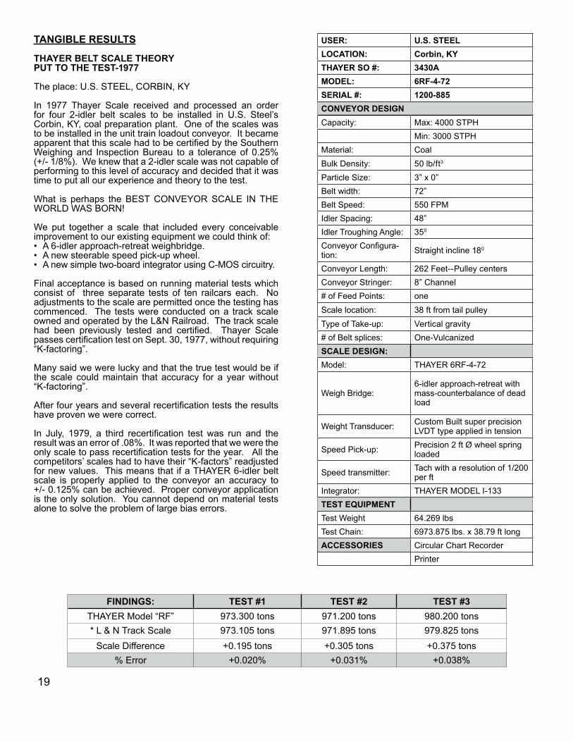
USER: U.S. STEELLOCATION: Corbin, KYTHAYER SO #: 3430AMODEL: 6RF-4-72SERIAL #: 1200-885CONVEYOR DESIGNCapacity: Max: 4000 STPH
Min: 3000 STPHMaterial: CoalBulk Density: 50 lb/ft3
Particle Size: 3” x 0”Belt width: 72”Belt Speed: 550 FPMIdler Spacing: 48”Idler Troughing Angle: 350
Conveyor Configura-tion: Straight incline 180
Conveyor Length: 262 Feet--Pulley centersConveyor Stringer: 8” Channel# of Feed Points: oneScale location: 38 ft from tail pulleyType of Take-up: Vertical gravity# of Belt splices: One-VulcanizedSCALE DESIGN:Model: THAYER 6RF-4-72
Weigh Bridge:6-idler approach-retreat with mass-counterbalance of dead load
Weight Transducer: Custom Built super precision LVDT type applied in tension
Speed Pick-up: Precision 2 ft Ø wheel spring loaded
Speed transmitter: Tach with a resolution of 1/200 per ft
Integrator: THAYER MODEL I-133 TEST EQUIPMENTTest Weight 64.269 lbsTest Chain: 6973.875 lbs. x 38.79 ft longACCESSORIES Circular Chart Recorder
Printer
TANGIBLE RESULTS
THAYER BELT SCALE THEORY PUT TO THE TEST-1977
The place: U.S. STEEL, CORBIN, KY
In 1977 Thayer Scale received and processed an order for four 2-idler belt scales to be installed in U.S. Steel’s Corbin, KY, coal preparation plant. One of the scales was to be installed in the unit train loadout conveyor. It became apparent that this scale had to be certified by the Southern Weighing and Inspection Bureau to a tolerance of 0.25% (+/- 1/8%). We knew that a 2-idler scale was not capable of performing to this level of accuracy and decided that it was time to put all our experience and theory to the test.
What is perhaps the BEST CONVEYOR SCALE IN THE WORLD WAS BORN!
We put together a scale that included every conceivable improvement to our existing equipment we could think of: A 6-idler approach-retreat weighbridge. A new steerable speed pick-up wheel. A new simple two-board integrator using C-MOS circuitry.
Final acceptance is based on running material tests which consist of three separate tests of ten railcars each. No adjustments to the scale are permitted once the testing has commenced. The tests were conducted on a track scale owned and operated by the L&N Railroad. The track scale had been previously tested and certified. Thayer Scale passes certification test on Sept. 30, 1977, without requiring “K-factoring”.
Many said we were lucky and that the true test would be if the scale could maintain that accuracy for a year without “K-factoring”.
After four years and several recertification tests the results have proven we were correct.
In July, 1979, a third recertification test was run and the result was an error of .08%. It was reported that we were the only scale to pass recertification tests for the year. All the competitors’ scales had to have their “K-factors” readjusted for new values. This means that if a THAYER 6-idler belt scale is properly applied to the conveyor an accuracy to +/- 0.125% can be achieved. Proper conveyor application is the only solution. You cannot depend on material tests alone to solve the problem of large bias errors.
•••
FINDINGS: TEST #1 TEST #2 TEST #3THAYER Model “RF” 973.300 tons 971.200 tons 980.200 tons* L & N Track Scale 973.105 tons 971.895 tons 979.825 tons
Scale Difference +0.195 tons +0.305 tons +0.375 tons% Error +0.020% +0.031% +0.038%
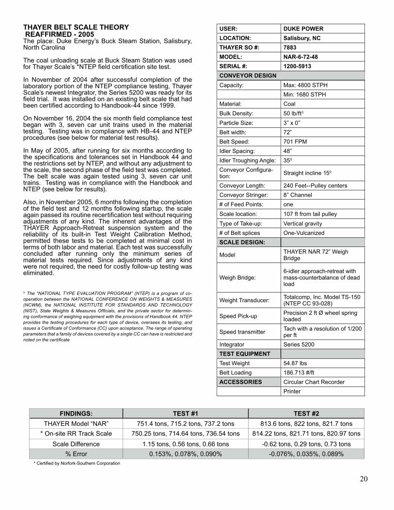
THAYER BELT SCALE THEORY REAFFIRMED - 2005The place: Duke Energy’s Buck Steam Station, Salisbury, North Carolina
The coal unloading scale at Buck Steam Station was used for Thayer Scale’s *NTEP field certification site test.
In November of 2004 after successful completion of the laboratory portion of the NTEP compliance testing, Thayer Scale’s newest Integrator, the Series 5200 was ready for its field trial. It was installed on an existing belt scale that had been certified according to Handbook-44 since 1999.
On November 16, 2004 the six month field compliance test began with 3, seven car unit trains used in the material testing. Testing was in compliance with HB-44 and NTEP procedures (see below for material test results).
In May of 2005, after running for six months according to the specifications and tolerances set in Handbook 44 and the restrictions set by NTEP, and without any adjustment to the scale, the second phase of the field test was completed. The belt scale was again tested using 3, seven car unit trains. Testing was in compliance with the Handbook and NTEP (see below for results).
Also, in November 2005, 6 months following the completion of the field test and 12 months following startup, the scale again passed its routine recertification test without requiring adjustments of any kind. The inherent advantages of the THAYER Approach-Retreat suspension system and the reliability of its built-in Test Weight Calibration Method, permitted these tests to be completed at minimal cost in terms of both labor and material. Each test was successfully concluded after running only the minimum series of material tests required. Since adjustments of any kind were not required, the need for costly follow-up testing was eliminated.
* The “NATIONAL TYPE EVALUATION PROGRAM” (NTEP) is a program of co-operation between the NATIONAL CONFERENCE ON WEIGHTS & MEASURES (NCWM), the NATIONAL INSTITUTE FOR STANDARDS AND TECHNOLOGY (NIST), State Weights & Measures Officials, and the private sector for determin-ing conformance of weighing equipment with the provisions of Handbook 44. NTEP provides the testing procedures for each type of device, oversees its testing, and issues a Certificate of Conformance (CC) upon acceptance. The range of operating parameters that a family of devices covered by a single CC can have is restricted and noted on the certificate
USER: DUKE POWERLOCATION: Salisbury, NCTHAYER SO #: 7883MODEL: NAR-6-72-48SERIAL #: 1200-5913CONVEYOR DESIGNCapacity: Max: 4800 STPH
Min: 1680 STPHMaterial: CoalBulk Density: 50 lb/ft3
Particle Size: 3” x 0”Belt width: 72”Belt Speed: 701 FPMIdler Spacing: 48”Idler Troughing Angle: 350
Conveyor Configura-tion: Straight incline 150
Conveyor Length: 240 Feet--Pulley centersConveyor Stringer: 8” Channel# of Feed Points: oneScale location: 107 ft from tail pulleyType of Take-up: Vertical gravity# of Belt splices One-VulcanizedSCALE DESIGN:
Model THAYER NAR 72” Weigh Bridge
Weigh Bridge:6-idler approach-retreat with mass-counterbalance of dead load
Weight Transducer: Totalcomp, Inc. Model TS-150 (NTEP CC 93-028)
Speed Pick-up Precision 2 ft Ø wheel spring loaded
Speed transmitter Tach with a resolution of 1/200 per ft
Integrator Series 5200TEST EQUIPMENTTest Weight 54.87 lbsBelt Loading 186.713 #/ftACCESSORIES Circular Chart Recorder
Printer
FINDINGS: TEST #1 TEST #2THAYER Model “NAR” 751.4 tons, 715.2 tons, 737.2 tons 813.6 tons, 822 tons, 821.7 tons
* On-site RR Track Scale 750.25 tons, 714.64 tons, 736.54 tons 814.22 tons, 821.71 tons, 820.97 tonsScale Difference 1.15 tons, 0.56 tons, 0.66 tons -0.62 tons, 0.29 tons, 0.73 tons
% Error 0.153%, 0.078%, 0.090% -0.076%, 0.035%, 0.089%* Certified by Norfork-Southern Corporation
20
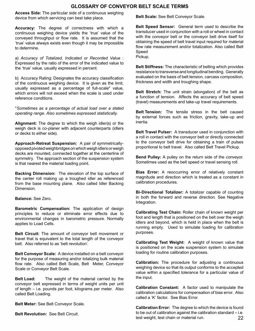
To aid in scale and conveyor design THAYER maintains a Belt Scale Suspension Testing Conveyor at its corporate headquarter in Pembroke, MA. This test conveyor was originally designed to study the effects of changing conveyor parameters on the accuracy of a particular scale’s loading signal as well as to compare the long term stability and reliability of speed measurements made at various locations within the conveyor. Currently it is used as an evolutionary development tool, where proposed design recommendations are simultaneously tested under identical conditions against existing configurations.
This test conveyor is 24” wide, 50 ft long, and can be equipped with 20 or 35 degree troughed idlers at variable spacing. It can operate under controlled belt tension from 500 to 1500 pounds, and belt speeds from 10 to 400 fpm. The conveyor is located outdoors to best simulate a customer’s installation and the effects of the environment (temperature swings of -150 F to +900 F) on scale performance.
The conveyor is equipped with a THAYER single idler Model “Quarry King” and 4 idler Model RF, Rocking Flexure Belt Scale. Both scales are outfitted with Thayer’s various instrumentation packages.
The potential performance level of a conveyor belt scale installation is dependent on things other than the belt scale itself. Major factors include: conveyor design, scale suspension design, location of load and speed sensors in relation to both conveyor terminal equipment and loading points, installed alignment conditions, duration and constancy of loading cycle, condition of rolling conveyor elements, the uniformity and stiffness of the belting itself, condition and size of take-up apparatus, the precision with the system can be routinely calibrated, adherence to calibration schedule, and operating environment.
While the Belt Scale Suspension Testing Conveyor can not simulate all the factors that directly effect a belt scale’s performance, it does provide many of the crucial variations in order to assure that a THAYER Belt Scale is designed for optimal accuracy and performance.
Belt Scale Suspension Testing Conveyor
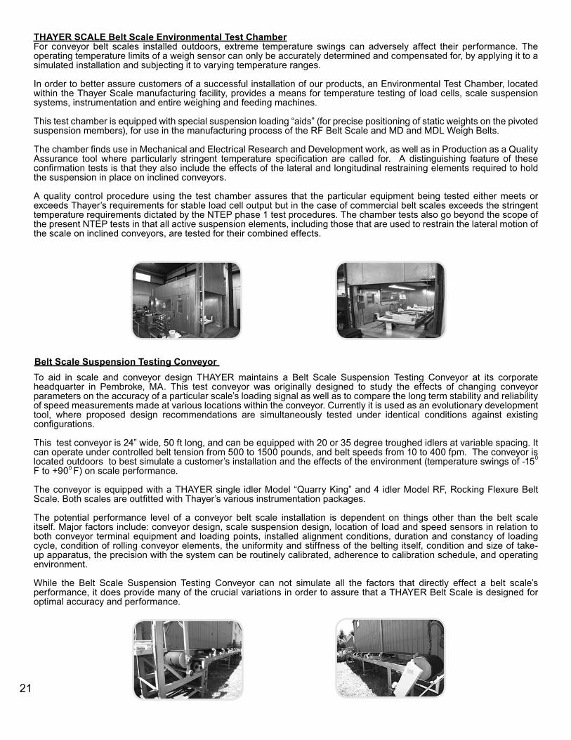
THAYER SCALE Belt Scale Environmental Test ChamberFor conveyor belt scales installed outdoors, extreme temperature swings can adversely affect their performance. The operating temperature limits of a weigh sensor can only be accurately determined and compensated for, by applying it to a simulated installation and subjecting it to varying temperature ranges.
In order to better assure customers of a successful installation of our products, an Environmental Test Chamber, located within the Thayer Scale manufacturing facility, provides a means for temperature testing of load cells, scale suspension systems, instrumentation and entire weighing and feeding machines. This test chamber is equipped with special suspension loading “aids” (for precise positioning of static weights on the pivoted suspension members), for use in the manufacturing process of the RF Belt Scale and MD and MDL Weigh Belts.
The chamber finds use in Mechanical and Electrical Research and Development work, as well as in Production as a Quality Assurance tool where particularly stringent temperature specification are called for. A distinguishing feature of these confirmation tests is that they also include the effects of the lateral and longitudinal restraining elements required to hold the suspension in place on inclined conveyors. A quality control procedure using the test chamber assures that the particular equipment being tested either meets or exceeds Thayer’s requirements for stable load cell output but in the case of commercial belt scales exceeds the stringent temperature requirements dictated by the NTEP phase 1 test procedures. The chamber tests also go beyond the scope of the present NTEP tests in that all active suspension elements, including those that are used to restrain the lateral motion of the scale on inclined conveyors, are tested for their combined effects.
21
Access Side: The particular side of a continuous weighing device from which servicing can best take place.
Accuracy: The degree of correctness with which a continuous weighing device yields the ‘true’ value of the conveyed throughput or flow rate. It is assumed that the ‘true’ value always exists even though it may be impossible to determine.
a) Accuracy of Totalized, Indicated or Recorded Value :Expressed by the ratio of the error of the indicated value to the ‘true’ value, usually expressed in percent.
b) Accuracy Rating: Designates the accuracy classification of the continuous weighing device. It is given as the limit, usually expressed as a percentage of full-scale* value, which errors will not exceed when the scale is used under reference conditions.
*Sometimes as a percentage of actual load over a stated operating range. Also sometimes expressed statistically.
Alignment: The degree to which the weigh idler(s) or the weigh deck is co-planer with adjacent counterparts (idlers or decks to either side).
Approach-Retreat Suspension: A pair of symmetrically-opposed pivoted weighbridges on which weigh idlers or weigh decks are mounted, connected together at the centerline of symmetry. The approach section of the suspension system is that nearest the material loading point.
Backing Dimension: The elevation of the top surface of the center roll making up a troughed idler as referenced from the base mounting plane. Also called Idler Backing Dimension.
Balance: See Zero.
Barometric Compensation: The application of design principles to reduce or eliminate error effects due to environmental changes in barometric pressure. Normally applies to Load Cells.
Belt Circuit: The amount of conveyor belt movement or travel that is equivalent to the total length of the conveyor belt. Also referred to as ‘belt revolution’.
Belt Conveyor Scale: A device installed on a belt conveyor for the purpose of measuring and/or totalizing bulk material flow rate. Also called Belt Scale, Belt Meter, Conveyor Scale or Conveyor Belt Scale.
Belt Load: The weight of the material carried by the conveyor belt expressed in terms of weight units per unit of length – i.e. pounds per foot, kilograms per meter. Also called Belt Loading.
Belt Meter: See Belt Conveyor Scale.
Belt Revolution: See Belt Circuit.
Belt Scale: See Belt Conveyor Scale.
Belt Speed Sensor: General term used to describe the transducer used in conjunction with a roll or wheel in contact with the conveyor belt or the conveyor belt drive itself for obtaining the speed of belt travel input required for material flow rate measurement and/or totalization. Also called Belt SpeedPickup.
Belt Stiffness: The characteristic of belting which provides resistance to transverse and longitudinal bending. Generally evaluated on the basis of belt tension, carcass composition, thickness and width and troughing shape.
Belt Stretch: The unit strain (elongation) of the belt as a function of tension. Affects the accuracy of belt speed (travel) measurements and take-up travel requirements.
Belt Tension: The tensile stress in the belt caused by external forces such as friction, gravity, take-up and inertia.
Belt Travel Pulser: A transducer used in conjunction with a roll in contact with the conveyor belt or directly connected to the conveyor belt drive for obtaining a train of pulses proportional to belt travel. Also called Belt Travel Pickup.
Bend Pulley: A pulley on the return side of the conveyor. Sometimes used as the belt speed or travel sensing roll.
Bias Error: A reoccurring error of relatively constant magnitude and direction which is treated as a constant in calibration procedures.
Bi-Directional Totalizer: A totalizer capable of counting in both the forward and reverse direction. See Negative Integration.
Calibrating Test Chain: Roller chain of known weight per foot and length that is positioned on the belt over the weigh idlers and beyond, which is held in place when the belt is running empty. Used to simulate loading for calibration purposes.
Calibrating Test Weight: A weight of known value that is positioned on the scale suspension system to simulate loading for routine calibration purposes.
Calibration: The procedure for adjusting a continuous weighing device so that its output conforms to the accepted value within a specified tolerance for a particular value of the input.
Calibration Constant: A factor used to manipulate the calibration calculations for compensation of bias error. Also called a ‘K’ factor. See Bias Error.
Calibration Error: The degree to which the device is found to be out of calibration against the calibration standard – i.e. test weight, test chain or material run.
GLOSSARY OF CONVEYOR BELT SCALE TERMS
22
Calibration Point: Refers to the specific value represented by the calibrating standard. Normally selected to fall in the range of 2/3 to 3/4 of the full loading value for belt conveyor scales.
Capacity: The maximum designed flow range of the continuous weighing device.
Carcass: The structural or reinforcement material in a conveyor belt. Normally cotton, nylon, rayon or a combination thereof.
Concave Curve: A change in the angle of a belt conveyor where the center of curvature is located above the conveyor.
Continuous Weighing: Weighing material while it is in motion. The weighing of loads without causing them to stop on the load receiving element of a scale.
Convex Curve: A change in the angle of a belt conveyor where the center of curvature is located below the conveyor.
Conveyor Angle: The degree of inclination or declination of a section of conveyor relative to horizontal. Also called Inclination Angle or Slope Angle.
Conveyor Belt Scale/Conveyor Scale: See Belt Conveyor Scale.
Count Rate: Advancement rate of totalizer’s unit digits when operating at capacity. Usually stated in number of counts per minute.
Count Transducer: Device adaptable to mechanical type integrator for purpose of transducing mechanical rotation (integrator output) into electrical pulses.
Counterbalance/Counterpoise/Counterweight: An adjustable, removable, usually slotted weight intended to balance against an applied load or designated weight value.
Dash Pot: A damping device, sometimes adjustable; it usually comprises a cylinder and piston relative motion of which displaces air, oil or other fluid.
Deflection: The displacement from zero to full load of the weigh deck or the most weight-sensitive idler on a belt scale.
Deflection Errors: Errors associated with belt tension and stiffness relative to the degree of scale deflection.
Digital Tachometer: A transducer whose output is a pulse train having frequency proportional to input velocity.
Drag Link: A restraining member usually a section of chain, rod or bar connected to the weighbridge to limit longitudinal motion. Also see Stabilizing Plate and Stabilizing Flexure.
Drift: The output deviation of the continuous weighing device over time with reference conditions remaining constant.
Effective Weigh Span: A span of conveyor belt equal to the product of the idler spacing and the number of weigh idlers. Under conditions of uniform loading the scale is subjected to a force equivalent to the product of effective weighspan and loading per unit length.
Empty Balance/Empty Belt Balance: See Zero.
Error: The difference between the indicated value and the true value of the measurement. When the indicated value is higher than the true value the sign of the error is positive.
Excitation Voltage: The recommended input voltage applied to a transducer.
Expansion Joint: A joint between two conveyor stringers designed to accommodate expansion and contraction of structural parts.
Flexural Pivot: A part or group of parts utilizing one or more elastic elements in place of frictional bearing surfaces to produce a bearing or pivot-like action.
Flexure Plate: A single element flexural pivot.
Force Alignment: Aligning the scale so that its output under simulated loading conditions does not change under conditions of varying tension.
Frequency Response: Two relations between sets of sinusoidal inputs and the resulting outputs. One relates frequencies to the output-input amplitude rations; theother to phase difference between output and input.
Fulcrum: The major support on or against which a lever rests.
Full-Floating Suspension: A weighbridge that is totally supported by the scale without ancillary support assistance. Term commonly used to distinguish from pivoted type weighbridges.
Gravimetric Measurement: Measurement based on the gravitational attraction or earth pull on a body (mass). Distinguished from nuclear measurements which are based on the absorption of radiation (gamma, beta radiation).
Gravity Take-Up: A horizontal pulley free to move in either the vertical or horizontal direction with dead weights applied to the pulley shaft to provide the belt tension desired in a conveyor.
Handbook 44: The National Conference of Weights and Measures text covering specifications, tolerances and other technical requirements for commercial weighing and measuring devices (see NIST)
23
Hydraulic Load Cell: A force transducer in which hydraulically generated pressure becomes the counterbalancing force.
Hysteresis: The maximum differences between the upscale and downscale output values during a full range traverse in each direction.
Inclination Angle: See Conveyor Angle.
Instantaneous Rate: The product of the belt load and speed signals at any given point in time. Expressed in units of weight per unit of time, i.e. tons per hour, pounds per minute, kilograms per minute, etc.
Integrator: A transducer whose output is the time integral of its input. In a continuous weighing device instantaneous flow rate is integrated with respect to time to yield total throughput.
K Factor: The K-Factor is an integrator pre-programmed span multiplier that affects the weigh measurement in the weigh mode only. It allows automatic compensation of a pre-established bias error, as determined through statistical evaluation of material test data.
Linearity: The closeness to which a curve approximates a straight line.
Load Button: A spherical load bearing element used to provide point contact in contrast to a knife-edge which provides line contact.
Load Cell: A transducer which provides an output signal proportional to the applied force. Also called Force Transducer, Load Transducer, Weight Transducer, Load Reactor, Load Sensor.
Loading Point: Refers to the location on a conveyor where the material is received by the belt. The location of a hopper, chute or the discharge of pre-feed device used to supply material to a conveyor.
Load Signal: An output signal corresponding to the instantaneous load (lbs/feet) on a belt scale or weigh feeder. Not to be confused with ‘rate signal’ which is the product of load and speed.
Load-Out Scale: A continuous weighing device used to control the delivery of a pre-set weight of material.
Load Reactor: That which opposes or counterbalances an applied load. Might be a load cell, simple spring or weight.
Location Error: That portion of bias error primarily attributable to the difference in belt tension at the scale under normal running and calibration conditions. The farther the scale is from the loading point and the greater the conveyor inclination, the higher the tension difference and hence the larger the location error.
Low Load Alarm: An audible or visual indication that instantaneous belt loading is below a pre-set limit.
Low Load Cut-Out: Provisions for discontinuing the integration of flow rate when instantaneous belt loading is below a pre-set limit. A means for eliminating the accumulation of zero errors over long periods of empty conveyor operation.
Low Rate Alarm: An audible or visual indication that instantaneous flow rate is below a pre-set limit.
Low Rate Cut-Out: Provisions for discontinuing the integration of flow rate when instantaneous flow rate is below a pre-set limit.
LVDT: Linear Variable Differential Transformer. A frictionless AC displacement transducer designed to produce a linear electric output over a given range of armature travel.
Mass: The amount of matter as measured by its inertia.
Master Weight Totalizer: the primary indicating element of a continuous weighing device used to accumulate the weight of material which has been measured.
Material Slippage: The relative velocity of the conveyed material with respect to the belt. For accurate weighing slippage must not occur.
Material Test: The calibration method from which bias errors are evaluated and calibration constants derived. Either pass a pre-weighed quantity of material over or through the continuous weighing device in a manner as similar as feasible to actual operating conditions, or statically weigh ona suitable scale all material that has passed over or through the continuous weighing device. Consult Handbook 44 for specific precautions where commercial weighing is involved.
Mercury Pot & Float: A load reactor operating on buoyancy principles.
Min. & Max. Loading: The defined loading limits for preferred performance with a given belt conveyor scale or weigh feeder installation. Usually expressed in percent of rated capacity at constant speed or in weight units per unit length of conveyor belt.
Misalignment: The degree to which weigh idlers or weigh decks are not co-planner with adjacent idlers or decking to either side of the scale.
Modulus of Elasticity – Belting: The ratio of stress to strain of belt carcass material over a defined tension range.
Multiplier: A device whose output is the product of its inputs.
Negative Integration: Refers to the capability of a belt conveyor scale or weigh feeder integrator to establish a true (average) zero over both light and heavy sections of an empty belt. 24
Non-Contacting Scale: A scale that does not physically contact the conveyor belt. See Nuclear Scale.
Non-Linearity: The deviation of any functional relationship from direct proportionality. The maximum deviation of the calibration curve from a straight line drawn through the no-load (zero) and the calibration point.
Normal Loading: The usual and accepted weight of material per unit length along the conveyor belt under normal operating conditions.
NTEP: National Type Evaluation Program. NTEP certification is issued by NCWM upon successful completion of the evaluation process. This Certificate indicates that the device manufacturer has demonstrated the ability to meet applicable requirements for commercial weighing and measuring equipment in the U.S as specified in NIST Handbook 44. NTEP certification is required in most states in the Unites States and is a symbol of assurance for all.
Nuclear Scale: A device consisting of a source of nuclear radiation and a detector for that radiation. Absorption of radiation determines the mass of the material passing between the source and the detector.
Null Balance: The act of counterbalancing the applied load to a null position. A deflectionless load reactor.
Overload: An instantaneous belt loading that exceeds a defined limit. Normally based on a structural limitation.
Overload Alarm: An audible or visual indication that instantaneous belt loading exceeds a predefined limit.
Over-Range: Excess capacity of a continuous weighing device.
OIML: Organisation Internationale de Métrologie Légale. International organization for legal metrology, is responsible for standardization of legal metrology in the associated countries. The International Organization of Legal Metrology (OIML) is an intergovernmental treaty organization whose membership includes Member States, countries which participate actively in technical activities, and Corresponding Members, countries which join the OIML as observers. OIML has developed a worldwide technical structure that provides its members with metrological guidelines for the elaboration of national and regional requirements concerning the manufacture and use of measuring instruments for legal metrology applications.
Peak Loading: The maximum instantaneous load the belt scale or weigh feeder device must handle.
Peak Rate: The maximum instantaneous flow that the continuous weighing device must handle.
Pendulum Weight: A rotating type load reactor in which the counterbalancing moment increases as rotation swings a known weight away from a fulcrum in a pendulum manner.
Pivoted Weighbridge: A weighbridge that is hinged or pivoted at one end to the conveyor structure and attached to the load reactor on the other. The load reactor therefore sense the moment about the hinge or pivot as opposed to the actual weight on the weighbridge. Term commonly used to distinguish from full-floating type weighbridge.
Planar Moment of Inertia: refers to the moment of inertia of the carcass cross sectional area with respect to its centroidal axis.
Poise: A weight movable parallel to the longitudinal axis of a weighbeam whose position referenced to a fixed index constitutes the weight indication
Non-Contacting Scale: A scale that does not physically contact the conveyor belt. See Nuclear Scale.
Non-Linearity: The deviation of any functional relationship from direct proportionality. The maximum deviation of the calibration curve from a straight line drawn through the no-load (zero) and the calibration point.
Prototype Approval: The certification covering a specific model of equipment that it meets the minimum design and performance requirements of the applicable legal authority for commercial weighing purposes. Example: NTEP approval of belt conveyor scales.
Rate Signal: An output signal corresponding to the instantaneous flow rate of a continuous weighing device. Not to be confused with ‘load signal’.
Scale Service Idler: A conveyor belt idler that meets the scale manufacturer’s requirements for ‘accurate’ weighing. Specifications normally cover dimensional tolerances on idler concentricity and troughing profile.
Simulated Load Test: A span test using a calibrating test chain or weight in the case of a belt conveyor scale or weigh feeder, or a test plate in the case of a nuclear scale, to simulate actual material loading.
Slope Angle: See Conveyor Angle.
Speed Compensation: Integration on the basis of both belt loading and speed inputs. Distinguished from simple integration of load only (speed assumed constant).
Speed Measurement Location: Point on the conveyor belt where speed measurement is taken. Usually defined in terms of distance from head or tail pulley, tension or slack side of belt.
Speed Range: The maximum and minimum belt speed over which a belt conveyor scale or weigh feeder operates.
Stabilizing Plate: A restraining plate-like member connected to the weighbridge to counteract undesirable side forces..
25
Strain Gage: A device that changes its electrical resistance proportional to strain.
Stringers: The primary longitudinal conveyor (structural) members upon which the belt supporting idlers are attached.
Suspended Idler(s): Weigh idler(s). The idlers supported by the weighbridge.
Suspension Rods: The connecting link(s), usually vertical, between the load reactor and the weighbridge through which the force to be measured is transmitted.
Sway Stops: Mechanical stops placed adjacent to the weighbridge to limit lateral motion.
Tachometer Generator: A transducer whose output is a voltage proportional to input velocity.
Tare: The ‘dead’ weight supported or sensed by the continuous weighing device in addition to the weight of the bulk material being weighed. Usually consists of the weighbridge, weigh idlers, conveyor belting and material build-up on these parts.
Tare Build-Up: That portion of tare due to the adhesion or support of spilled material.
Test Chain: See Calibrating Test Chain.
Test Chain Rack: A trough (upside down section of channel) upon which a calibrating test chain is stored.
Test Chain Reel: A storage spool around which a calibrating test chain is wound for storage purposes.
Test Plate: A plate having a fixed absorption factor used to simulate material loading on a nuclear continuous weighing device for calibration checks.
Tolerance: The limit of allowable error or departure from true performance or value.
Tolerance, Acceptance: Tolerances applied to new or newly reconditioned or adjusted equipment. Usually one-half of the maintenance tolerance.
Tolerance, Maintenance: Tolerance that provides for additional range of inaccuracy within which equipment will be approved on subsequent tests, permitting a limited amount of deterioration before the equipment will be officially rejected and before reconditioning or readjustment will be required.
Totalizer: A device used to indicate the weight of material which has been conveyed over or passed through the continuous weighing device.
Training Idler: An idler of special design who function is to maintain central tracking of the belt.
Tripper: A special device for unloading a belt conveyor at a point between the loading point and the head pulley. Not to be confused with a diverting plow.
Troughing Angle: The angle that the edges of the belt are held up to reduce spillage or increase capacity. The inclination of the side rolls with respect to the center roll of a troughed idler.
Vernier: An auxiliary counter or dial, or equivalent function thereof, used with the master weight totalizer to increase resolution.
Weighbridge: The frame on which weigh idlers are secured. Also called Weigh Carriage.
Weighing Bureaus: Inspecting or certifying agencies.
Weigh Carriage: See Weighbridge.
Weigh Deck: The section of plate that is weighed in a slider plate type conveyor. Analogous to a weigh idler in a troughed or flat idler type conveyor.
Weigh Idler(s): The idlers supported by the weighbridge. Also called Suspended Idlers.
Weigh Length: See Effective Weigh Span.
Weigh Span: The distance between the two fixed idlers adjacent to either side of the belt conveyor scale.
Wind Break: Shroud positioned to protect scale from effects of wind and drafts.
Zero: Abbreviated term for empty balance, empty belt balance or balance as pertains to the calibration of a continuous weighing device. Properly adjusted zero infers a net zero integration of the empty belt over an exact belt revolution.
26
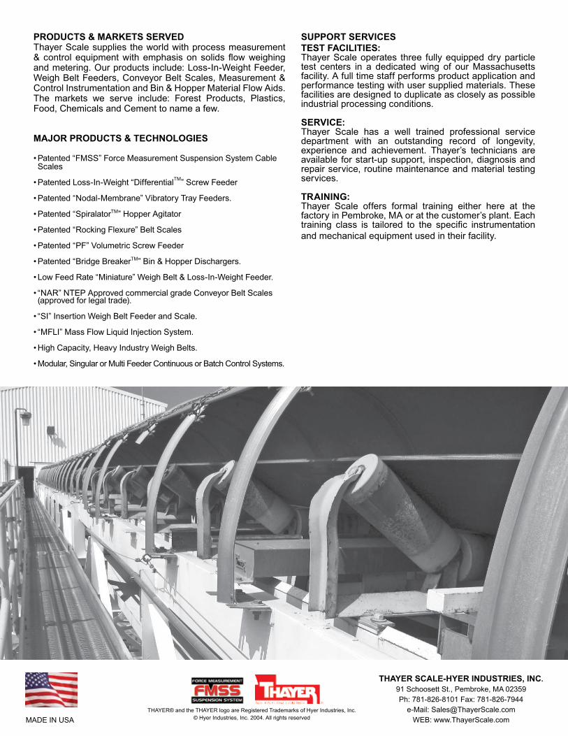
THAYER SCALE-HYER INDUSTRIES, INC.91 Schoosett St., Pembroke, MA 02359Ph: 781-826-8101 Fax: 781-826-7944
e-Mail: [email protected]: www.ThayerScale.comMADE IN USA
THAYER® and the THAYER logo are Registered Trademarks of Hyer Industries, Inc.© Hyer Industries, Inc. 2004. All rights reserved
PRODUCTS & MARKETS SERVEDThayer Scale supplies the world with process measurement & control equipment with emphasis on solids flow weighing and metering. Our products include: Loss-In-Weight Feeder, Weigh Belt Feeders, Conveyor Belt Scales, Measurement & Control Instrumentation and Bin & Hopper Material Flow Aids. The markets we serve include: Forest Products, Plastics, Food, Chemicals and Cement to name a few.
MAJOR PRODUCTS & TECHNOLOGIES
• Patented “FMSS” Force Measurement Suspension System Cable Scales
• Patented Loss-In-Weight “DifferentialTM” Screw Feeder
• Patented “Nodal-Membrane” Vibratory Tray Feeders.
• Patented “SpiralatorTM” Hopper Agitator
• Patented “Rocking Flexure” Belt Scales
• Patented “PF” Volumetric Screw Feeder
• Patented “Bridge BreakerTM” Bin & Hopper Dischargers.
• Low Feed Rate “Miniature” Weigh Belt & Loss-In-Weight Feeder.
• “NAR” NTEP Approved commercial grade Conveyor Belt Scales (approved for legal trade).
• “SI” Insertion Weigh Belt Feeder and Scale.
• “MFLI” Mass Flow Liquid Injection System.
• High Capacity, Heavy Industry Weigh Belts.
• Modular, Singular or Multi Feeder Continuous or Batch Control Systems.
SUPPORT SERVICESTEST FACILITIES:Thayer Scale operates three fully equipped dry particle test centers in a dedicated wing of our Massachusetts facility. A full time staff performs product application and performance testing with user supplied materials. These facilities are designed to duplicate as closely as possible industrial processing conditions.
SERVICE:Thayer Scale has a well trained professional service department with an outstanding record of longevity, experience and achievement. Thayer’s technicians are available for start-up support, inspection, diagnosis and repair service, routine maintenance and material testing services.
TRAINING:Thayer Scale offers formal training either here at the factory in Pembroke, MA or at the customer’s plant. Each training class is tailored to the specific instrumentation and mechanical equipment used in their facility.