engineering drawings- thayer
TRANSCRIPT

8/17/2019 Engineering Drawings- Thayer
http://slidepdf.com/reader/full/engineering-drawings-thayer 1/39
1
Principles of Engineering Drawing
Thayer Machine Shop

8/17/2019 Engineering Drawings- Thayer
http://slidepdf.com/reader/full/engineering-drawings-thayer 2/39
Drawing and Tolerancing
This Tutorial reviews the following principles:
Drawing: How to interpret and create engineering drawings
Dimensioning: How to communicate dimensions properly
Tolerancing: How to use geometric and dimensional tolerances
to specify how much variation is acceptable during manufacture

8/17/2019 Engineering Drawings- Thayer
http://slidepdf.com/reader/full/engineering-drawings-thayer 3/39
3
Why Engineering Drawings?
• Engineering drawing is a formal and precise way of
communicating information about the shape, size, featuresand precision of physical objects.
• Drawing is the universal language of engineering.
• Engineering drawing could be a complete course in itself, but we only have 80 minutes so...
This is only going to cover the very basics.

8/17/2019 Engineering Drawings- Thayer
http://slidepdf.com/reader/full/engineering-drawings-thayer 4/39
4
Drawing Standards• Just like written language has standards, the
“grammar” of technical drawing is defined by...
the ANSI Y14.5 or the ISO standard
• The ANSI standards must be understood to
read a drawing.• Lets look at a sample drawing...

8/17/2019 Engineering Drawings- Thayer
http://slidepdf.com/reader/full/engineering-drawings-thayer 5/39
5
MATERI AL: AL6601- T6
PART NAME: Lef t Mt g. Br acket
DRAWN BY: BC
DATE: 6- 1- 97REV:
NOTES:
TOL: QTY: 1
Uni t s i n I nches
Deburr al l edges

8/17/2019 Engineering Drawings- Thayer
http://slidepdf.com/reader/full/engineering-drawings-thayer 6/39
6
Basic Information Included in a Drawing
• Projected Views: Show as many sides as needed for completeness.
• Cross Sections: A view that is good for showing interior features.
• Table: Lower right corner, with material information, part name, designer etc.
and finally
• DIMENSIONS!!!: These are the most important and
most complicated part of the drawing. There is more to it than
just the numerical values!

8/17/2019 Engineering Drawings- Thayer
http://slidepdf.com/reader/full/engineering-drawings-thayer 7/39
7
Which is better?
0.750” + .003” 0.250” + .003”
1.000” + .003”0.250” + .003”

8/17/2019 Engineering Drawings- Thayer
http://slidepdf.com/reader/full/engineering-drawings-thayer 8/39
8
A Dimensioning Example,showing that placement should match intent
These drawings show bolts holes for mounting a flange onto a plate. When
mounting the flange, the position of the holes with respect to each other is very
important, or else the flange (or part) won’t fit. It makes sense to dimension thedistance between the holes, instead of the distances to the edge.
Dimension placement
matches intent
Dimension placement
does NOT match intent
0.750” + .003” 0.250” + .003”
1.000” + .003”0.250” + .003”

8/17/2019 Engineering Drawings- Thayer
http://slidepdf.com/reader/full/engineering-drawings-thayer 9/39
9
Tolerances(every part needs some)
There are two types of tolerances:
Dimensional Tolerances
and
Geometric Tolerances
8/17/2019 Engineering Drawings- Thayer
http://slidepdf.com/reader/full/engineering-drawings-thayer 10/39
10
What’s the difference?
• Dimensional tolerances control _______________.
• Geometric tolerances control __________ & __________.
Geometric tolerances affect dimensional tolerances!

8/17/2019 Engineering Drawings- Thayer
http://slidepdf.com/reader/full/engineering-drawings-thayer 11/39
11
Types of Dimensional Tolerances
Limit Dimensioning Plus & Minus Tolerancing
Both methods are acceptable.
1.371
1.379 1.375 + .004

8/17/2019 Engineering Drawings- Thayer
http://slidepdf.com/reader/full/engineering-drawings-thayer 12/39
12
Tolerance Accumulation
The distance between X and Y is a critical dimension.
The total variation in the distance between X and Y
depends on how the drawing is dimensioned.
How much tolerance is specified on the distance
between X and Y in each example?
(a) +
(b) +
(c) +

8/17/2019 Engineering Drawings- Thayer
http://slidepdf.com/reader/full/engineering-drawings-thayer 13/39
13
Geometric Tolerancing
Geometric Tolerancing is used to specify the shape of features.
Things like:
•Straightness
•Flatness•Circularity
•Cylindricity
•Angularity
Geometric Tolerances are shown on a drawing with a feature control frame.
•Profiles
•Perpendicularity•Parallelism
•Concentricity
•And More...
8/17/2019 Engineering Drawings- Thayer
http://slidepdf.com/reader/full/engineering-drawings-thayer 14/39
14
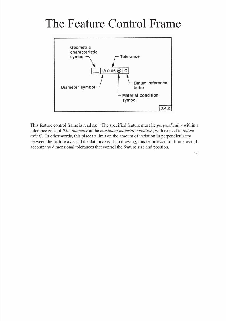
The Feature Control Frame
This feature control frame is read as: “The specified feature must lie perpendicular within a
tolerance zone of 0.05 diameter at the maximum material condition, with respect to datum
axis C . In other words, this places a limit on the amount of variation in perpendicularity
between the feature axis and the datum axis. In a drawing, this feature control frame would
accompany dimensional tolerances that control the feature size and position.

8/17/2019 Engineering Drawings- Thayer
http://slidepdf.com/reader/full/engineering-drawings-thayer 15/39
15
Geometric Characteristic Symbols
A feature control frame gives information about geometric
tolerances on the feature.

8/17/2019 Engineering Drawings- Thayer
http://slidepdf.com/reader/full/engineering-drawings-thayer 16/39
16
Straightness Example

8/17/2019 Engineering Drawings- Thayer
http://slidepdf.com/reader/full/engineering-drawings-thayer 17/39
17
Straightness at MMC

8/17/2019 Engineering Drawings- Thayer
http://slidepdf.com/reader/full/engineering-drawings-thayer 18/39
18
DemoSketch your observations:
2 Rods: .375” diameter
.750” diameter
Tube with .755” hole

8/17/2019 Engineering Drawings- Thayer
http://slidepdf.com/reader/full/engineering-drawings-thayer 19/39
19
Flatness Examples

8/17/2019 Engineering Drawings- Thayer
http://slidepdf.com/reader/full/engineering-drawings-thayer 20/39
20
Parallelism Example

8/17/2019 Engineering Drawings- Thayer
http://slidepdf.com/reader/full/engineering-drawings-thayer 21/39
21
Circularity (Roundness) Example

8/17/2019 Engineering Drawings- Thayer
http://slidepdf.com/reader/full/engineering-drawings-thayer 22/39
22
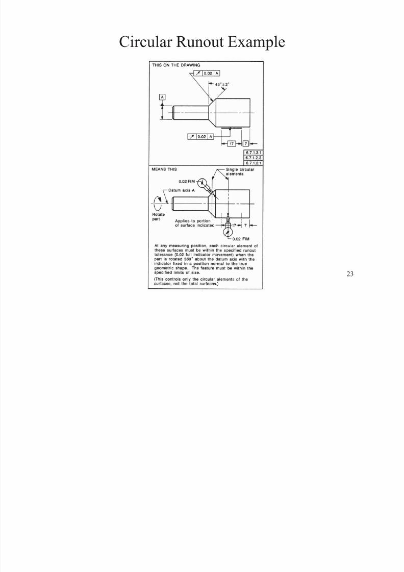
Circular & Total Runout
Runout is specified on cylindrical parts. It ismeasured by placing a gage on the part, and
rotating the part through 360 degrees. The
total variation is recorded as the runout.
• Circular runout is measured at one location.
• Total Runout is measured along the entirespecified surface.
8/17/2019 Engineering Drawings- Thayer
http://slidepdf.com/reader/full/engineering-drawings-thayer 23/39
23
Circular Runout Example

8/17/2019 Engineering Drawings- Thayer
http://slidepdf.com/reader/full/engineering-drawings-thayer 24/39
24
Total Runout Example

8/17/2019 Engineering Drawings- Thayer
http://slidepdf.com/reader/full/engineering-drawings-thayer 25/39
25
Cylindricity Example

8/17/2019 Engineering Drawings- Thayer
http://slidepdf.com/reader/full/engineering-drawings-thayer 26/39
26
Perpendicularity Example

8/17/2019 Engineering Drawings- Thayer
http://slidepdf.com/reader/full/engineering-drawings-thayer 27/39
27
Angularity Example
Measuring angularity is
equivalent to measuring parallelism at an angle.

8/17/2019 Engineering Drawings- Thayer
http://slidepdf.com/reader/full/engineering-drawings-thayer 28/39
28
Conventional (Coordinate) Tolerancing
Tolerance Zone Boundary
Hole Center Axis
.750 + .005
2.000 + .005
.600 + .005
1.500 + .005
This dimensional tolerance
controls the size of the 3 holes.
The other dimensional tolerances
control the positions.
A
.010”
.010”

8/17/2019 Engineering Drawings- Thayer
http://slidepdf.com/reader/full/engineering-drawings-thayer 29/39
29
In the conventional tolerancing scheme, a hole center axis can reside
anywhere in the square tolerance zone. The drawing may call out linear
tolerances of +.005”, but....005”
.005”
By how much can the hole location deviate from spec?
8/17/2019 Engineering Drawings- Thayer
http://slidepdf.com/reader/full/engineering-drawings-thayer 30/39
30
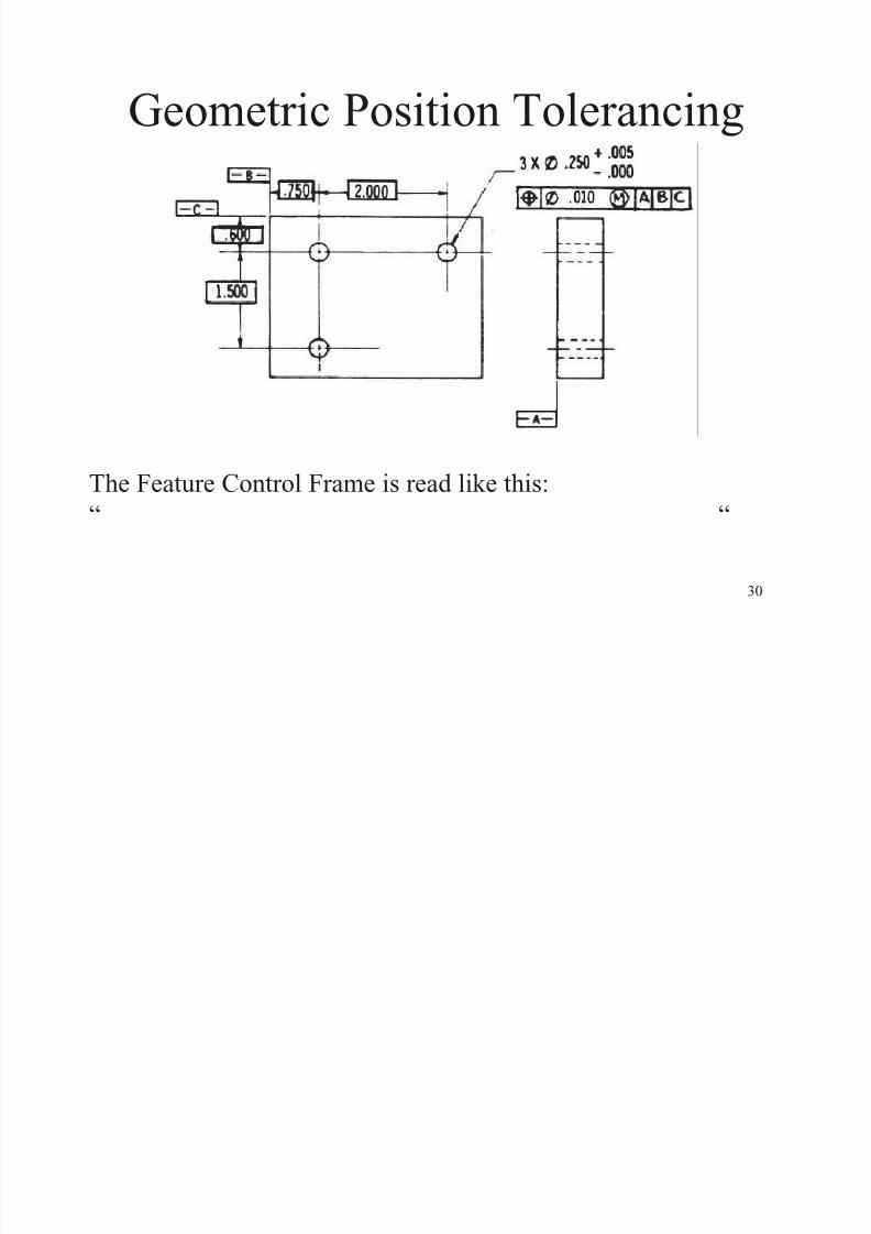
Geometric Position Tolerancing
The Feature Control Frame is read like this:“ “

8/17/2019 Engineering Drawings- Thayer
http://slidepdf.com/reader/full/engineering-drawings-thayer 31/39
31
MMC vs. LMC
SMALLEST
HOLE
SMALLESTSHAFT
LARGEST
HOLE
LARGESTSHAFT
“Maximum Material Condition” “Least Material Condition”

8/17/2019 Engineering Drawings- Thayer
http://slidepdf.com/reader/full/engineering-drawings-thayer 32/39
32
Tolerance Zone Size
This feature control frame specifies the tolerance
zone as a circle of diameter .010 at MMC,
centered according to the basic dimensions given.The size of the tolerance zone is dependent on the
size of the hole.
A feature control frame can specify the size of the
tolerance zone at MMC, LMC or RFS (regardless
of feature size).
MMC of hole = .250
LMC of hole = .255
Hole diameter Tolerance Zone diameter
.250 (MMC) .010
.251 .011
.252 .012
.253 .013
.254 .014
.255 (LMC) .015

8/17/2019 Engineering Drawings- Thayer
http://slidepdf.com/reader/full/engineering-drawings-thayer 33/39
33
Determining Tolerance Zone Size

8/17/2019 Engineering Drawings- Thayer
http://slidepdf.com/reader/full/engineering-drawings-thayer 34/39
34
Does this feature meet the true position tolerance?
Step 1: What can we measure?

8/17/2019 Engineering Drawings- Thayer
http://slidepdf.com/reader/full/engineering-drawings-thayer 35/39
35
Step 2:
Calculate deviations in x and y directions.How does this compare to the basic dimensions?

8/17/2019 Engineering Drawings- Thayer
http://slidepdf.com/reader/full/engineering-drawings-thayer 36/39
36
222 y x Z
Tolerance zone, dia. = TZ
Desired position
Actual hole center
A hole center that deviates from true position by x
and y lies within a tolerance zone of diameter Z. If
Z > TZ, the part is bad.
Step 3:
Determining the TruePosition

8/17/2019 Engineering Drawings- Thayer
http://slidepdf.com/reader/full/engineering-drawings-thayer 37/39
37
True Position and Perpendicularity
This feature control frame specifies the true position
tolerance of the hole with respect to 3 datum planes.
The order that the datum planes are listed in the feature
control frame indicates the priority of each datum.
Datums B and C provide reference for the x and y
position of the hole center, and datum A controls the
perpendicularity of the hole axis .
Referencing datum A means that the center axis of the hole must be perpendicular to
datum plane A. The axis must intersect
datum plane A inside the tolerance zone
.010” wide tolerance zone
Permissible hole
axis variation
-A-

8/17/2019 Engineering Drawings- Thayer
http://slidepdf.com/reader/full/engineering-drawings-thayer 38/39
38
Standard Fits• Standard Fits are a way of specifying a fit
between a hole and a shaft. RC (1-9) Running or Sliding Clearance Fit
LC (1-11) Locational Clearance Fit
LT (1-6) Transition Clearance or Interference Fit
LN (1-3) Locational Interference Fit
FN (1-5) Force or Shrink Fit
We mention this here because it will be useful in dimension the parts of your yo-yo that must snap fit together.
Ref: Marks’ Mechanical Engineering Handbook, 6th ed. McGraw-Hill.
Standard Fit Example

8/17/2019 Engineering Drawings- Thayer
http://slidepdf.com/reader/full/engineering-drawings-thayer 39/39
39
Standard Fit Example
There is a nominal diameter of 1 inch for the shaft and hole on your yo-yo. You want a
class FN2 fit. What should the dimensions and tolerances be for the shaft and the hole?