test report · high -low temp cabinet suzhou zhihe tl -40 shem087 -1 2017 -09 -25 2020 -09 -24 ac...
TRANSCRIPT

SGS-CSTC Standards Technical Services
(Shanghai) Co., Ltd.
Report No.: SHEM190501327703 Page: 1 of 25
The CE mark as show n below can be used, under the responsibility of the manufacturer, after completion of an EU Declaration of Conformity and compliance w ith all relevant EU Directives.
Parlam Zhan E&E Section Manager
The manufacturer should ensure that all products in series production are in conformity w ith the produc t sample detailed in this report. If the product in this report is used in any configuration other than that detailed in the report, the manufacturer must ensure the new system complies w ith all relevant standards. Any mention of SGS International Electrical Approvals or testing done by SGS International Electrical Approvals in connection with, distribution or use of the product described in this report must be approved by
SGS International Electrical Approvals in w riting.
TEST REPORT Application No.: SHEM1905013277CR
Applicant: Hangzhou Hikvision Digital Technology Co., Ltd.
Address of Applicant: No.555 Qianmo Road, Binjiang District, Hangzhou 310052, China
Manufacturer: Hangzhou Hikvision Digital Technology Co., Ltd.
Address of Manufacturer: No.555 Qianmo Road, Binjiang District, Hangzhou 310052, China
Factory: 1. Hangzhou Hikvision Technology Co., Ltd.
2. Hangzhou Hikvision Electronics Co., Ltd.
Address of Factory: 1. No.700, Dongliu Road, Binjiang District, Hangzhou City, Zhejiang,
310052, China
2. No.299, Qiushi Road, Tonglu Economic Development Zone, Tonglu
County, Hangzhou, Zhejiang, 310052, China.
Equipment Under Test (EUT):
EUT Name: Wireless Tag Reader
Model No.: DS-PTA-WL-868, DS-PTA-WL-868UHK, DS-PTA-WL-868CKV, DS-PTA-
WL-868UVS, DS-PTA-WL-868KVO, DS-PTA-WL-868HUN ¤
¤ Please refer to section 2 of this report which indicates which model was
actually tested and which were electrically identical.
Trade mark: HIKVISION
Standard(s) : EN 300 220-1 V3.1.1, EN 300 220-2 V3.2.1
Date of Receipt: 2019-05-16
Date of Test: 2019-05-22 to 2019-05-25
Date of Issue: 2019-06-21
Test Result: Pass*
* In the configuration tested, the EUT complied with the standards specified above.
SGS-CSTC Standards Technical Services (Shanghai) Co., Ltd.
Report No.: SHEM190501327703 Page: 2 of 25
Revision Record
Version Description Date Remark
00 Original 2019-06-21 /
Authorized for issue by:
Vincent Zhu /Project Engineer
Eddy Zong / Reviewer
SGS-CSTC Standards Technical Services (Shanghai) Co., Ltd.
Report No.: SHEM190501327703 Page: 3 of 25
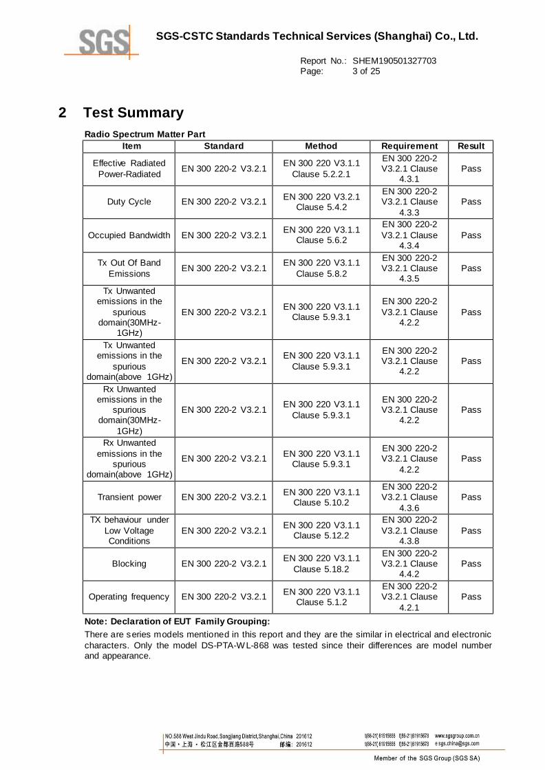
2 Test Summary
Radio Spectrum Matter Part
Item Standard Method Requirement Result
Effective Radiated
Power-Radiated EN 300 220-2 V3.2.1
EN 300 220 V3.1.1
Clause 5.2.2.1
EN 300 220-2 V3.2.1 Clause
4.3.1 Pass
Duty Cycle EN 300 220-2 V3.2.1 EN 300 220 V3.2.1
Clause 5.4.2
EN 300 220-2 V3.2.1 Clause
4.3.3
Pass
Occupied Bandwidth EN 300 220-2 V3.2.1 EN 300 220 V3.1.1
Clause 5.6.2
EN 300 220-2
V3.2.1 Clause 4.3.4
Pass
Tx Out Of Band
Emissions EN 300 220-2 V3.2.1
EN 300 220 V3.1.1
Clause 5.8.2
EN 300 220-2 V3.2.1 Clause
4.3.5 Pass
Tx Unwanted emissions in the
spurious domain(30MHz-
1GHz)
EN 300 220-2 V3.2.1 EN 300 220 V3.1.1
Clause 5.9.3.1
EN 300 220-2
V3.2.1 Clause 4.2.2
Pass
Tx Unwanted emissions in the
spurious domain(above 1GHz)
EN 300 220-2 V3.2.1 EN 300 220 V3.1.1
Clause 5.9.3.1
EN 300 220-2 V3.2.1 Clause
4.2.2 Pass
Rx Unwanted emissions in the
spurious domain(30MHz-
1GHz)
EN 300 220-2 V3.2.1 EN 300 220 V3.1.1
Clause 5.9.3.1
EN 300 220-2 V3.2.1 Clause
4.2.2 Pass
Rx Unwanted
emissions in the spurious
domain(above 1GHz)
EN 300 220-2 V3.2.1 EN 300 220 V3.1.1
Clause 5.9.3.1
EN 300 220-2 V3.2.1 Clause
4.2.2
Pass
Transient power EN 300 220-2 V3.2.1 EN 300 220 V3.1.1
Clause 5.10.2
EN 300 220-2 V3.2.1 Clause
4.3.6
Pass
TX behaviour under
Low Voltage Conditions
EN 300 220-2 V3.2.1 EN 300 220 V3.1.1
Clause 5.12.2
EN 300 220-2
V3.2.1 Clause 4.3.8
Pass
Blocking EN 300 220-2 V3.2.1 EN 300 220 V3.1.1
Clause 5.18.2
EN 300 220-2 V3.2.1 Clause
4.4.2 Pass
Operating frequency EN 300 220-2 V3.2.1 EN 300 220 V3.1.1
Clause 5.1.2
EN 300 220-2 V3.2.1 Clause
4.2.1
Pass
Note: Declaration of EUT Family Grouping:
There are series models mentioned in this report and they are the similar in electrical and electronic
characters. Only the model DS-PTA-WL-868 was tested since their differences are model number and appearance.

SGS-CSTC Standards Technical Services (Shanghai) Co., Ltd.
Report No.: SHEM190501327703 Page: 4 of 25
3 Contents
Page
1 COVER PAGE .................................................................................................................................. 1
2 TEST SUMMARY.............................................................................................................................. 3
3 CONTENTS ...................................................................................................................................... 4
4 GENERAL INFORMATION................................................................................................................ 5
4.1 DETAILS OF E.U.T. ...................................................................................................................... 5 4.2 ENVIRONMENT PARAMETER .......................................................................................................... 5 4.3 DESCRIPTION OF SUPPORT UNITS .................................................................................................. 5 4.4 MEASUREMENT UNCERTAINTY ....................................................................................................... 6 4.5 TEST LOCATION .......................................................................................................................... 7 4.6 TEST FACILITY ............................................................................................................................ 7 4.7 DEVIATION FROM STANDARDS ....................................................................................................... 7 4.8 ABNORMALITIES FROM STANDARD CONDITIONS ................................................................................ 7
5 EQUIPMENT LIST ............................................................................................................................ 8
6 RADIO SPECTRUM MATTER TEST RESULTS ................................................................................. 9
6.1 DUTY CYCLE............................................................................................................................... 9 6.2 OCCUPIED BANDWIDTH .............................................................................................................. 10 6.3 TX OUT OF BAND EMISSIONS ...................................................................................................... 11 6.4 TX UNWANTED EMISSIONS IN THE SPURIOUS DOMAIN(30MHZ-1GHZ) ................................................ 12 6.5 TX UNWANTED EMISSIONS IN THE SPURIOUS DOMAIN(ABOVE 1GHZ) .................................................. 13 6.6 RX UNWANTED EMISSIONS IN THE SPURIOUS DOMAIN(30MHZ-1GHZ) ................................................ 14 6.7 RX UNWANTED EMISSIONS IN THE SPURIOUS DOMAIN(ABOVE 1GHZ) .................................................. 15 6.8 TRANSIENT POWER .................................................................................................................... 16 6.9 TX BEHAVIOUR UNDER LOW VOLTAGE CONDITIONS ........................................................................ 17 6.10 BLOCKING ................................................................................................................................ 18 6.11 OPERATING FREQUENCY............................................................................................................. 19 6.12 EFFECTIVE RADIATED POWER-RADIATED ...................................................................................... 20
7 PHOTOGRAPHS ............................................................................................................................ 21
APPENDIX A FOR SHEM190501327703 ................................................................................................. 21
SGS-CSTC Standards Technical Services (Shanghai) Co., Ltd.
Report No.: SHEM190501327703 Page: 5 of 25
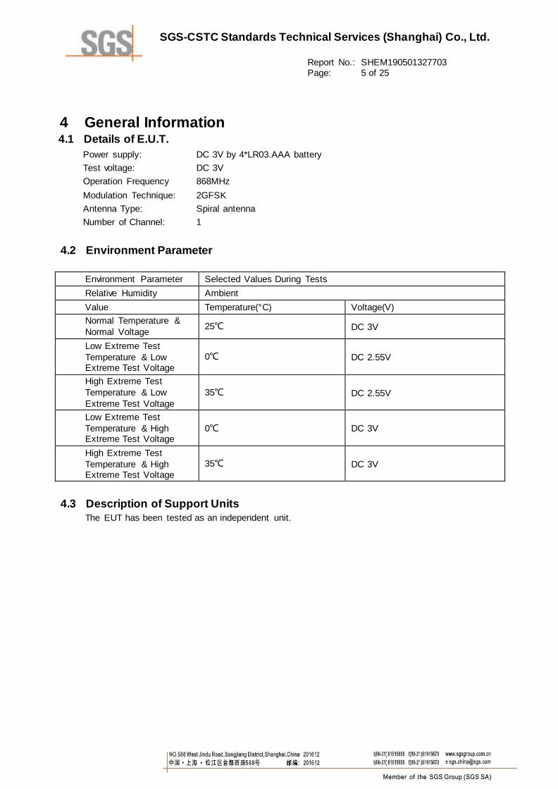
4 General Information 4.1 Details of E.U.T.
Power supply: DC 3V by 4*LR03.AAA battery
Test voltage: DC 3V
Operation Frequency 868MHz
Modulation Technique: 2GFSK
Antenna Type: Spiral antenna
Number of Channel: 1
4.2 Environment Parameter
Environment Parameter Selected Values During Tests
Relative Humidity Ambient
Value Temperature(°C) Voltage(V)
Normal Temperature &
Normal Voltage 25℃ DC 3V
Low Extreme Test
Temperature & Low Extreme Test Voltage
0℃ DC 2.55V
High Extreme Test
Temperature & Low
Extreme Test Voltage
35℃ DC 2.55V
Low Extreme Test
Temperature & High Extreme Test Voltage
0℃ DC 3V
High Extreme Test
Temperature & High Extreme Test Voltage
35℃ DC 3V
4.3 Description of Support Units
The EUT has been tested as an independent unit.

SGS-CSTC Standards Technical Services (Shanghai) Co., Ltd.
Report No.: SHEM190501327703 Page: 6 of 25
4.4 Measurement Uncertainty
No. Item Measurement Uncertainty
1 Radio Frequency ±8.4 x 10⁻⁸
2 Timeout ±2s
3 Duty cycle ±0.37%
4 Occupied Bandwidth ±3%
5 RF conducted power ±0.6dB
6 RF power density ±2.84dB
7 Conducted Spurious emissions ±0.75dB
8 RF Radiated power ±4.6dB (Below 1GHz)
±4.1dB (Above 1GHz)
9 Radiated Spurious emission test
±4.2dB (Below 30MHz)
±4.4dB (30MHz-1GHz)
±4.8dB (1GHz-18GHz)
±5.2dB (Above 18GHz)
10 Temperature test ±1°C
11 Humidity test ±3%
12 Supply voltages ±1.5%
13 Time ±3%
Note: The measurement uncertainty represents an expanded uncertainty expressed at approximately the
95% confidence level using a coverage factor of k=2.

SGS-CSTC Standards Technical Services (Shanghai) Co., Ltd.
Report No.: SHEM190501327703 Page: 7 of 25
4.5 Test Location
All tests were performed at:
SGS-CSTC Standards Technical Services (Shanghai) Co., Ltd. E&E Lab
588 West Jindu Road, Xinqiao, Songjiang, 201612 Shanghai, China
Tel: +86 21 6191 5666 Fax: +86 21 6191 5678
No tests were sub-contracted.
4.6 Test Facility
The test facility is recognized, certified, or accredited by the following organizations:
• CNAS (No. CNAS L0599)
CNAS has accredited SGS-CSTC Standards Technical Services (Shanghai) Co., Ltd. to ISO/IEC
17025:2005 General Requirements for the Competence of Testing and Calibration Laboratories
(CNAS-CL01 Accreditation Criteria for the Competence of Testing and Calibration Laboratories) for
the competence in the field of testing.
• NVLAP (Certificate No. 201034-0)
SGS-CSTC Standards Technical Services (Shanghai) Co., Ltd. is accredited by the National
Voluntary Laboratory Accreditation Program(NVLAP). Certificate No. 201034-0.
• FCC –Designation Number: CN5033
SGS-CSTC Standards Technical Services (Shanghai) Co., Ltd. has been recognized as an
accredited testing laboratory.
Designation Number: CN5033. Test Firm Registration Number: 479755.
• Innovation, Science and Economic Development Canada
SGS-CSTC Standards Technical Services (Shanghai) Co., Ltd. EMC Laboratory has been
recognized by ISED as an accredited testing laboratory.
IC Registration No.: 8617A-1. CAB identifier: CN0020.
• VCCI (Member No.: 3061)
The 3m Semi-anechoic chamber and Shielded Room of SGS-CSTC Standards Technical Services
(Shanghai) Co., Ltd. has been registered in accordance with the Regulations for Voluntary Control
Measures with Registration No.: R-13868, C-14336, T-12221, G-10830 respectively.
4.7 Deviation from Standards
None
4.8 Abnormalities from Standard Conditions
None

SGS-CSTC Standards Technical Services (Shanghai) Co., Ltd.
Report No.: SHEM190501327703 Page: 8 of 25
5 Equipment List
Equipment Manufacturer Model No Inventory No Cal Date Cal Due Date
Conducted Test
Spectrum Analyzer R&S FSP-30 SHEM002-1 2018-12-20 2019-12-19
Spectrum Analyzer Agilent N9020A SHEM181-1 2018-08-13 2019-08-12
Signal Generator R&S SMR20 SHEM006-1 2018-08-13 2019-08-12
Signal Generator Agilent N5182A SHEM182-1 2018-08-13 2019-08-12
Communication Tester R&S CMW270 SHEM183-1 2018-08-13 2019-08-12
Switcher Tonscend JS0806 SHEM184-1 2018-08-13 2019-08-12
Power Sensor Keysight U2021XA * 4 SHEM184-1 2018-08-13 2019-08-12
Splitter Anritsu MA1612A SHEM185-1 / /
Coupler e-meca 803-S-1 SHEM186-1 / /
High-low Temp Cabinet Suzhou Zhihe TL-40 SHEM087-1 2017-09-25 2020-09-24
AC Power Stabilizer WOCEN 6100 SHEM045-1 2018-12-26 2019-12-25
DC Power Supply MCN MCH-303A SHEM210-1 2018-12-26 2019-12-25
Conducted test Cable / RF01~RF04 / 2018-12-26 2019-12-25
Radiated Test
EMI test Receiver R&S ESU40 SHEM051-1 2018-12-20 2019-12-19
Spectrum Analyzer R&S FSP-30 SHEM002-1 2018-12-20 2019-12-19
Loop Antenna (9kHz-30MHz) Schwarzbeck FMZB1519 SHEM135-1 2017-04-10 2020-04-09
Antenna (25MHz-2GHz) Schwarzbeck VULB9168 SHEM048-1 2017-02-28 2020-02-27
Antenna (25MHz-3GHz) Schwarzbeck HL562 SHEM010-1 2017-02-28 2020-02-27
Horn Antenna (1-8GHz) Schwarzbeck HF906 SHEM009-1 2017-10-24 2020-10-23
Horn Antenna (1-18GHz) Schwarzbeck BBHA9120D SHEM050-1 2017-01-14 2020-01-13
Horn Antenna (14-40GHz) Schwarzbeck BBHA 9170 SHEM049-1 2017-12-03 2020-12-02
Pre-amplifier (9KHz-2GHz) CLAVIIO BDLNA-0001 SHEM164-1 2018-08-13 2019-08-12
Pre-amplifier (1-18GHz) CLAVIIO BDLNA-0118 SHEM050-2 2018-08-13 2019-08-12
High-amplifier (14-40GHz) Schwarzbeck 10001 SHEM049-2 2018-12-20 2019-12-19
Signal Generator R&S SMR40 SHEM058-1 2018-08-13 2019-08-12
Band Filter LORCH 9BRX-875/X150 SHEM156-1 / /
Band Filter LORCH 13BRX-1950/X500 SHEM083-2 / /
Band Filter LORCH 5BRX-2400/X200 SHEM155-1 / /
Band Filter LORCH 5BRX-5500/X1000 SHEM157-2 / /
High pass Filter Wainwright WHK3.0/18G SHEM157-1 / /
High pass Filter Wainwright WHKS1700 SHEM157-3 / /
Semi/Fully Anechoic ST 11*6*6M SHEM078-2 2017-07-22 2020-07-21
RE test Cable / RE01, RE02, RE06 / 2018-12-26 2019-12-25

SGS-CSTC Standards Technical Services (Shanghai) Co., Ltd.
Report No.: SHEM190501327703 Page: 9 of 25
6 Radio Spectrum Matter Test Results
6.1 Duty Cycle
Test Requirement EN 300 220-2 V3.2.1 Clause 4.3.3
Test Method: EN 300 220-2 V3.2.1 Clause 5.4.2
Limit:
Table 6: Minimum of hop channels and other requirements for FHSS
Sub-band Number of hop
channels/bandwidth (BW)
865 MHz to 868 MHz ≥ 58 at ≤ 50 kHz BW each LBT or < 1 % TX duty cycle (see note 1)
863 MHz to 870 MHz
(see note 2) ≥ 47 at ≥ 100 kHz BW each LBT or < 0,1 % TX duty cycle (see note 1)
NOTE 1: The duty cycle applies to the entire transmission (not at each hopping channel).
NOTE 2: FHSS as shown in the present table shall not be used in the frequency bands for alarms
as defined in tables 1 and 5.
6.1.1 E.U.T. Operation
Operating Environment:
Temperature: 21 C Humidity: 45 % RH Atmospheric Pressure: 1010 mbar
Test mode b:TX mode_Keep the EUT in transmitting mode
6.1.2 Measurement Procedure and Data
1) The EUT shall be set to operate for not less than 10 transmissions
2) Using suitable analysis software the start time and stop time of each sequence of samples above
PThreshold shall be obtained. Between the saved start and stop times of each individual burst, the TOn time shall be calculated. These TOn values shall be saved. Between the saved stop and start
times of two subsequent bursts, the TOff time shall be calculated. These TOff values shall be saved.
3) Within the calculated TOff times, any interval less than Tdis shall be discarded
4) Calculate the duty cycle on an observation interval.
The detailed test data see: Appendix A for SHEM190501327703

SGS-CSTC Standards Technical Services (Shanghai) Co., Ltd.
Report No.: SHEM190501327703 Page: 10 of 25
6.2 Occupied Bandwidth
Test Requirement EN 300 220-2 V3.2.1 Clause 4.3.4
Test Method: EN 300 220 V3.1.1 Clause 5.6.2
Limit:
Table 7: Maximum radiated power density, bandwidth and duty cycle limits
for other spread spectrum than FHSS
Sub-band Maximum Occupied
bandwidth
Maximum radiated
power density
e.r.p.
Duty cycle
865 MHz to 868 MHz 0,6 MHz 6,2 dBm / 100 kHz 1%
865 MHz to 870 MHz 3,0 MHz -0,8 dBm / 100 kHz 0.1%
863 MHz to 870 MHz 7,0 MHz -4,5 dBm / 100 kHz 0.1%
6.2.1 E.U.T. Operation
Operating Environment:
Temperature: 21 C Humidity: 45 % RH Atmospheric Pressure: 1010 mbar
Test mode b:TX mode_Keep the EUT in transmitting mode
6.2.2 Measurement Procedure and Data
The spectrum analyser shall be configured as below:
Set RBW: 1 % to 3 % of OCW without being below 100 Hz
VBW: >=3*RBW
Span: >=2 x Operating Channel width
Detector Mode: RMS
Trace: Max hold
When the trace is completed the peak value of the trace shall be located and the analyser marker
placed on this peak.
The 99 % occupied bandwidth function of the spectrum analyser shall be used to measure the
occupied bandwidth of the signal.
The detailed test data see: Appendix A for SHEM190501327703

SGS-CSTC Standards Technical Services (Shanghai) Co., Ltd.
Report No.: SHEM190501327703 Page: 11 of 25
6.3 Tx Out Of Band Emissions
Test Requirement EN 300 220-2 V3.2.1 Clause 4.3.5
Test Method: EN 300 220 V3.1.1 Clause 5.8.2
Limit:
Table 9: Adjacent channel power limits applicable to narrowband systems
Channel separation < 20 kHz Channel separation >=20 kHz
Normal test conditions 10uW 200nW
Extreme test conditions 32uW 640nW
NOTE: These limits also apply to spread spectrum equipment.
6.3.1 E.U.T. Operation
Operating Environment:
Temperature: 21 C Humidity: 45 % RH Atmospheric Pressure: 1010 mbar
Test mode b:TX mode_Keep the EUT in transmitting mode
6.3.2 Measurement Procedure and Data
1) The test equipment shall be configured as below:
Centre frequency = Operating Frequency
Span = 6 x Operating Channel width
RBW = 1 kHz
Detector Function = RMS
Trace Mode = Linear AVG / Max Hold
Operation of the EUT shall be started, on the highest operating frequency as declared by the
manufacturer, with the appropriate test signal.
The signal shape is recorded when stable and shall be below the spectrum mask Out Of Band for
operating channel.
2) The test equipment shall be reconfigured as below:
Centre frequency = fclow
Span = 2 x (500 kHz + fclow - flow_OFB)
Operation of the EUT is restarted, with the appropriate test signal, on the lowest operating frequency
as declared by the manufacturer.
If the equipment is using only one operating Frequency in the operational Frequency Band,
measurement shall be performed the nominal operating frequency.
The signal shape is recorded when stable; and shall be below the spectrum mask for operating
channel and the spectrum mask for operational frequency band.
3) The test equipment shall be reconfigured as below:
Centre frequency = fchigh
Span = 2 x (500 kHz + fhigh_OFB - fchigh)
Operation of the EUT is restarted, with the appropriate test signal, on the highest Operating
Frequency as declared by the manufacturer.
4) The signal shape is recorded when stable and shall be below the spectrum mask for Out Of Band
emissions for operating channel and for operational Frequency Band.
5) The measurements in step 1 to step 5 shall be repeated under extreme test conditions.
The detailed test data see: Appendix A for SHEM190501327703

SGS-CSTC Standards Technical Services (Shanghai) Co., Ltd.
Report No.: SHEM190501327703 Page: 12 of 25
6.4 Tx Unwanted emissions in the spurious domain(30MHz-1GHz)
Test Requirement EN 300 220-2 V3.2.1 Clause 4.2.2
Test Method: EN 300 220 V3.1.1 Clause 5.9.3.1
Limit:
Table 11: Spurious domain emission limits
Frequency
State
47 MHz to 74 MHz
87,5 MHz to 118 MHz
174 MHz to 230 MHz
470 MHz to 862 MHz
Other frequencies
below 1 000 MHz
Frequencies
above 1 000 MHz
Operating 4 nW 250 nW
Standby 2 nW 2 nW 20 nW
6.4.1 E.U.T. Operation
Operating Environment:
Temperature: 21 C Humidity: 45 % RH Atmospheric Pressure: 1010 mbar
Test mode b:TX mode_Keep the EUT in transmitting mode
6.4.2 Measurement Procedure and Data
An initial pre-scan was performed in the chamber using the spectrum analyser in peak detection
mode. Quasi-peak measurements were conducted based on the peak sweep graph. The EUT was measured by BiConiLog antenna with 2 orthogonal polarities.
The detailed test data see: Appendix A for SHEM190501327703

SGS-CSTC Standards Technical Services (Shanghai) Co., Ltd.
Report No.: SHEM190501327703 Page: 13 of 25
6.5 Tx Unwanted emissions in the spurious domain(above 1GHz)
Test Requirement EN 300 220-2 V3.2.1 Clause 4.2.2
Test Method: EN 300 220 V3.1.1 Clause 5.9.3.1
Limit:
Table 11: Spurious domain emission limits
Frequency
State
47 MHz to 74 MHz
87,5 MHz to 118 MHz
174 MHz to 230 MHz
470 MHz to 862 MHz
Other frequencies
below 1 000 MHz
Frequencies
above 1 000 MHz
Operating 4 nW 250 nW
Standby 2 nW 2 nW 20 nW
6.5.1 E.U.T. Operation
Operating Environment:
Temperature: 21 C Humidity: 45 % RH Atmospheric Pressure: 1010 mbar
Test mode b:TX mode_Keep the EUT in transmitting mode
6.5.2 Measurement Procedure and Data
An initial pre-scan was performed in the chamber using the spectrum analyser in peak detection
mode. Quasi-peak measurements were conducted based on the peak sweep graph. The EUT was measured by BiConiLog antenna with 2 orthogonal polarities.
The detailed test data see: Appendix A for SHEM190501327703

SGS-CSTC Standards Technical Services (Shanghai) Co., Ltd.
Report No.: SHEM190501327703 Page: 14 of 25
6.6 Rx Unwanted emissions in the spurious domain(30MHz-1GHz)
Test Requirement EN 300 220-2 V3.2.1 Clause 4.2.2
Test Method: EN 300 220 V3.1.1 Clause 5.9.3.1
Limit:
The equipment shall either:
a) remain on channel, for channelized equipment within the limits stated in clause 7.1.3, or within the assigned operating frequency band, for non-channelized equipment, whilst the radiated or conducted
power is greater than the spurious emission limits; or
b) the equipment cease to function below the providers declared operating voltage.
6.6.1 E.U.T. Operation
Operating Environment:
Temperature: 21 C Humidity: 45 % RH Atmospheric Pressure: 1010 mbar
Test mode b:TX mode_Keep the EUT in transmitting mode
6.6.2 Measurement Procedure and Data
An initial pre-scan was performed in the chamber using the spectrum analyser in peak detection
mode. Quasi-peak measurements were conducted based on the peak sweep graph. The EUT was measured by BiConiLog antenna with 2 orthogonal polarities.
The detailed test data see: Appendix A for SHEM190501327703

SGS-CSTC Standards Technical Services (Shanghai) Co., Ltd.
Report No.: SHEM190501327703 Page: 15 of 25
6.7 Rx Unwanted emissions in the spurious domain(above 1GHz)
Test Requirement EN 300 220-2 V3.2.1 Clause 4.2.2
Test Method: EN 300 220 V3.1.1 Clause 5.9.3.1
6.7.1 E.U.T. Operation
Operating Environment:
Temperature: 21 C Humidity: 45 % RH Atmospheric Pressure: 1010 mbar
Test mode b:TX mode_Keep the EUT in transmitting mode
6.7.2 Measurement Procedure and Data
An initial pre-scan was performed in the chamber using the spectrum analyser in peak detection
mode. Quasi-peak measurements were conducted based on the peak sweep graph. The EUT was measured by BiConiLog antenna with 2 orthogonal polarities.
The detailed test data see: Appendix A for SHEM190501327703
SGS-CSTC Standards Technical Services (Shanghai) Co., Ltd.
Report No.: SHEM190501327703 Page: 16 of 25
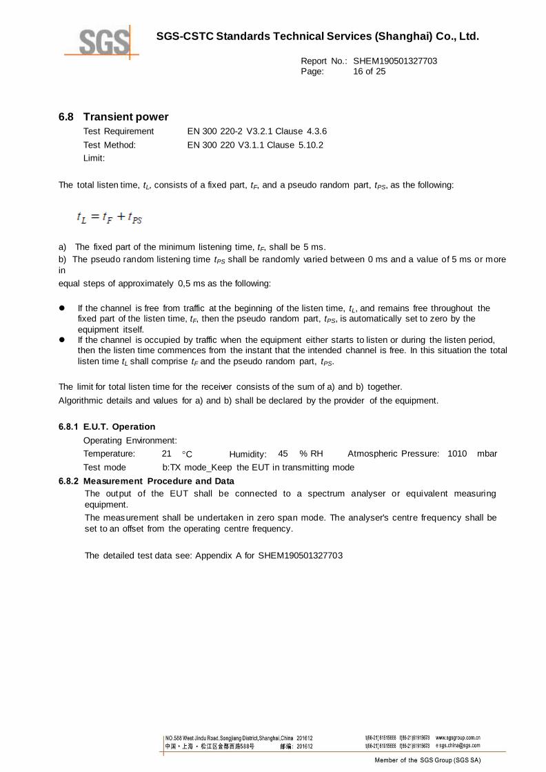
6.8 Transient power
Test Requirement EN 300 220-2 V3.2.1 Clause 4.3.6
Test Method: EN 300 220 V3.1.1 Clause 5.10.2
Limit:
The total listen time, tL, consists of a fixed part, tF, and a pseudo random part, tPS, as the following:
a) The fixed part of the minimum listening time, tF, shall be 5 ms.
b) The pseudo random listening time tPS shall be randomly varied between 0 ms and a value of 5 ms or more
in
equal steps of approximately 0,5 ms as the following:
If the channel is free from traffic at the beginning of the listen time, tL, and remains free throughout the fixed part of the listen time, tF, then the pseudo random part, tPS, is automatically set to zero by the
equipment itself. If the channel is occupied by traffic when the equipment either starts to listen or during the listen period,
then the listen time commences from the instant that the intended channel is free. In this situation the total
listen time tL shall comprise tF and the pseudo random part, tPS.
The limit for total listen time for the receiver consists of the sum of a) and b) together.
Algorithmic details and values for a) and b) shall be declared by the provider of the equipment.
6.8.1 E.U.T. Operation
Operating Environment:
Temperature: 21 C Humidity: 45 % RH Atmospheric Pressure: 1010 mbar
Test mode b:TX mode_Keep the EUT in transmitting mode
6.8.2 Measurement Procedure and Data
The output of the EUT shall be connected to a spectrum analyser or equivalent measuring
equipment.
The measurement shall be undertaken in zero span mode. The analyser's centre frequency shall be
set to an offset from the operating centre frequency.
The detailed test data see: Appendix A for SHEM190501327703
SGS-CSTC Standards Technical Services (Shanghai) Co., Ltd.
Report No.: SHEM190501327703 Page: 17 of 25
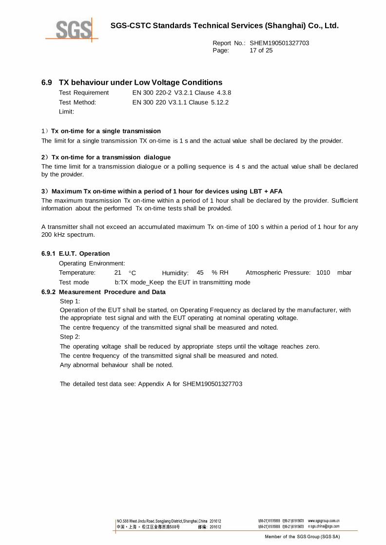
6.9 TX behaviour under Low Voltage Conditions
Test Requirement EN 300 220-2 V3.2.1 Clause 4.3.8
Test Method: EN 300 220 V3.1.1 Clause 5.12.2
Limit:
1)Tx on-time for a single transmission
The limit for a single transmission TX on-time is 1 s and the actual value shall be declared by the provider.
2)Tx on-time for a transmission dialogue
The time limit for a transmission dialogue or a polling sequence is 4 s and the actual value shall be declared
by the provider.
3)Maximum Tx on-time within a period of 1 hour for devices using LBT + AFA
The maximum transmission Tx on-time within a period of 1 hour shall be declared by the provider. Sufficient
information about the performed Tx on-time tests shall be provided.
A transmitter shall not exceed an accumulated maximum Tx on -time of 100 s within a period of 1 hour for any
200 kHz spectrum.
6.9.1 E.U.T. Operation
Operating Environment:
Temperature: 21 C Humidity: 45 % RH Atmospheric Pressure: 1010 mbar
Test mode b:TX mode_Keep the EUT in transmitting mode
6.9.2 Measurement Procedure and Data
Step 1:
Operation of the EUT shall be started, on Operating Frequency as declared by the manufacturer, with
the appropriate test signal and with the EUT operating at nominal operating voltage.
The centre frequency of the transmitted signal shall be measured and noted.
Step 2:
The operating voltage shall be reduced by appropriate steps until the voltage reaches zero.
The centre frequency of the transmitted signal shall be measured and noted.
Any abnormal behaviour shall be noted.
The detailed test data see: Appendix A for SHEM190501327703
SGS-CSTC Standards Technical Services (Shanghai) Co., Ltd.
Report No.: SHEM190501327703 Page: 18 of 25
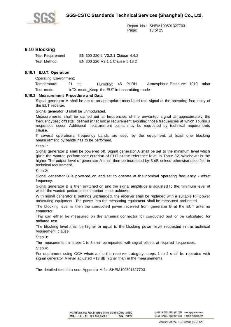
6.10 Blocking
Test Requirement EN 300 220-2 V3.2.1 Clause 4.4.2
Test Method: EN 300 220 V3.1.1 Clause 5.18.2
6.10.1 E.U.T. Operation
Operating Environment:
Temperature: 21 C Humidity: 45 % RH Atmospheric Pressure: 1010 mbar
Test mode b:TX mode_Keep the EUT in transmitting mode
6.10.2 Measurement Procedure and Data
Signal generator A shall be set to an appropriate modulated test signal at the operating frequency of
the EUT receiver.
Signal generator B shall be unmodulated.
Measurements shall be carried out at frequencies of the unwanted signal at approximately the
frequency(ies) offset(s) defined in technical requirement avoiding those frequencies at which spurious responses occur. Additional measurement points may be requested by technical requirements
clause.
If several operational frequency bands are used by the equipment, at least one blocking
measurement by bands has to be performed.
Step 1:
Signal generator B shall be powered off. Signal generator A shall be set to the minimum level which
gives the wanted performance criterion of EUT or the reference level in Table 32, whichever is the
higher The output level of generator A shall then be increased by 3 dB unless otherwise specified in technical requirement.
Step 2:
Signal generator B is powered on and set to operate at the nominal operating frequency - offset
frequency.
Signal generator B is then switched on and the signal amplitude is adjusted to the minimum level at which the wanted performance criterion is not achieved.
With signal generator B settings unchanged, the receiver shall be replaced with a suitable RF power
measuring equipment. The power into the measuring equipment shall be measured and noted.
The blocking level is then the conducted power received from generator B at the EUT antenna
connector.
This can either be measured on the antenna connector for conducted test or be calculated for
radiated test
The blocking level shall be higher or equal to the blocking power level requested in the technical
requirement clause.
Step 3:
The measurement in steps 1 to 3 shall be repeated with signal offsets at required frequencies.
Step 4:
For equipment using CCA whatever is the receiver category, steps 1 to 4 shall be repeated with
signal generator A level adjusted +13 dB higher than in the measurements.
The detailed test data see: Appendix A for SHEM190501327703

SGS-CSTC Standards Technical Services (Shanghai) Co., Ltd.
Report No.: SHEM190501327703 Page: 19 of 25
6.11 Operating frequency
Test Requirement EN 300 220-2 V3.2.1 Clause 4.2.1
Test Method: EN 300 220 V3.1.1 Clause 5.1.2
6.11.1 E.U.T. Operation
Operating Environment:
Temperature: 21 C Humidity: 45 % RH Atmospheric Pressure: 1010 mbar
Test mode b:TX mode_Keep the EUT in transmitting mode
6.11.2 Measurement Procedure and Data
The detailed test data see: Appendix A for SHEM190501327703

SGS-CSTC Standards Technical Services (Shanghai) Co., Ltd.
Report No.: SHEM190501327703 Page: 20 of 25
6.12 Effective Radiated Power-Radiated
Test Requirement EN 300 220-2 V3.2.1 Clause 4.3.1
Test Method: EN 300 220 V3.1.1 Clause 5.2.2.1
Limit:
Table 7: Maximum radiated power density, bandwidth and duty cycle limits
Sub-band Maximum Occupied
bandwidth
Maximum radiated
power density
e.r.p.
Duty cycle
868.00MHz to
868.60MHz The whole band 25 mW 1%
6.12.1 E.U.T. Operation
Operating Environment:
Temperature: 21 C Humidity: 45 % RH Atmospheric Pressure: 1010 mbar
Test mode b:TX mode_Keep the EUT in transmitting mode
6.12.2 Measurement Procedure and Data
1). The EUT was powered ON and placed on a 1.5m high table in the chamber. The antenna of the
transmitter was extended to its maximum length. Receiver mode and the measuring receiver shall be tuned to the frequency of the transmitter under test.
2). The disturbance of the transmitter was maximized on the test receiver display by raising and
lowering from 1m to 4m the receive antenna and by rotating through 360° the turntable. After the undamental emission was maximized, a field strength measurement was made.
3). Steps 1) and 2) were performed with the EUT and the receive antenna in both vertical and
horizontal polarization.
4). The transmitter was then removed and replaced with another antenna. The center of the antenna
was approximately at the same location as the center of the transmitter.
5). A signal at the disturbance was fed to the substitution antenna by means of a non-radiating cable.
With both the substitution and the receive antennas horizontally polarized, the receive antenna was raised and lowered to obtain a maximum reading at the test receiver. The level of the signal generator was adjusted until the measured field strength level in step 2) is obtained for this set of conditions.
6). The output power into the substitution antenna was then measured.
7). Steps 5) and 6) were repeated with both antennas polarized.
8) Calculate power in dBm by the following formula:
ERP(dBm) = Pg(dBm) – cable loss (dB) + antenna gain (dBd)
where:
Pg is the generator output power into the substitution antenna.
The detailed test data see: Appendix A for SHEM190501327703

SGS-CSTC Standards Technical Services (Shanghai) Co., Ltd.
Report No.: SHEM190501327703 Page: 21 of 25
7 Photographs
Refer to the < Photographs >
Appendix A for SHEM190501327703
a) Operation frequency
Measurement Conditions Operating
Frequency (MHz)
OCW
(KHz) Limit (MHz) Result
Tnormal Vnorm 868.028-868.134 106 868-868.6 Pass
b) Effective Radiated Power
Operation Frequency
Measurement Conditions
ERP Limit Result
868
Tnormal Vnorm 10.75dBm 14 dBm PASS
Tupper Vmax 10.84dBm 14 dBm PASS
Vmin 10.70dBm 14 dBm PASS
Tlower Vmax 10.82dBm 14 dBm PASS
Vmin 10.71dBm 14 dBm PASS
c) Duty Cycle
Total Ton (ms)
Tobs
(ms) Duty Cycle Limit Result
3255 3600000ms 0.0904% 0.1% Pass
d) Occupied Bandwidth
Measurement Conditions OBW (kHz) Limit (MHz) Result
Tnormal Vnorm 106.00 868-868.6 Pass
Tupper Vmax 106.25 868-868.6 Pass
Vmin 105.98 868-868.6 Pass
Tlower Vmax 106.05 868-868.6 Pass
Vmin 105.95 868-868.6 Pass

SGS-CSTC Standards Technical Services (Shanghai) Co., Ltd.
Report No.: SHEM190501327703 Page: 22 of 25
e) Tx Out of Band Emissions
Test Conditions
Frequency Range
Highest
Level Point
(dBm)
Limit
(dBm) Result
Temperature Voltage(DC)
Tnorm Vnorm
f ≤ flow - 400 kHz -47.88 -36 Pass
Flow - 400 kHz ≤ f ≤ flow - 200 kHz -42.68 -36 Pass
flow - 200 kHz ≤ f < flow -37.45 -36 to 0 Pass
Fhigh < f ≤ fhigh + 200 kHz -40.65 0 to -36 Pass
Fhigh + 200 kHz ≤ f ≤ fhigh + 400 kHz -41.25 -36 Pass
Fhigh + 400 kHz ≤ f -45.99 -36 Pass
Tupper
Vmax
f ≤ flow - 400 kHz -47.87 -36 Pass
Flow - 400 kHz ≤ f ≤ flow - 200 kHz -43.69 -36 Pass
flow - 200 kHz ≤ f < flow -37.87 -36 to 0 Pass
Fhigh < f ≤ fhigh + 200 kHz -40.73 0 to -36 Pass
Fhigh + 200 kHz ≤ f ≤ fhigh + 400 kHz -42.99 -36 Pass
Fhigh + 400 kHz ≤ f -45.48 -36 Pass
Vmin
f ≤ flow - 400 kHz -50.36 -36 Pass
Flow - 400 kHz ≤ f ≤ flow - 200 kHz -43.82 -36 Pass
flow - 200 kHz ≤ f < flow -42.42 -36 to 0 Pass
Fhigh < f ≤ fhigh + 200 kHz -40.59 0 to -36 Pass
Fhigh + 200 kHz ≤ f ≤ fhigh + 400 kHz -46.77 -36 Pass
Fhigh + 400 kHz ≤ f -48.69 -36 Pass
Tlower
Vmax
f ≤ flow - 400 kHz -47.77 -36 Pass
Flow - 400 kHz ≤ f ≤ flow - 200 kHz -44.29 -36 Pass
flow - 200 kHz ≤ f < flow -40.85 -36 to 0 Pass
Fhigh < f ≤ fhigh + 200 kHz -43.77 0 to -36 Pass
Fhigh + 200 kHz ≤ f ≤ fhigh + 400 kHz -44.97 -36 Pass
Fhigh + 400 kHz ≤ f -46.71 -36 Pass
Vmin
f ≤ flow - 400 kHz -46.28 -36 Pass
Flow - 400 kHz ≤ f ≤ flow - 200 kHz -43.01 -36 Pass
flow - 200 kHz ≤ f < flow -41.98 -36 to 0 Pass
Fhigh < f ≤ fhigh + 200 kHz -40.28 0 to -36 Pass
Fhigh + 200 kHz ≤ f ≤ fhigh + 400 kHz -43.74 -36 Pass
Fhigh + 400 kHz ≤ f -45.28 -36 Pass
Note: -36 to 0&0 to -36 Decreases with the linear of the frequency

SGS-CSTC Standards Technical Services (Shanghai) Co., Ltd.
Report No.: SHEM190501327703 Page: 23 of 25
f) Transient Power
Measurement points:
offset from centre frequency
Transient Power(dBm)
at analyser RBW
Transient Power
(dBm) at RBW ref
Limit
(dBm) Result
-0,5 x OCW - 3 kHz -25.68@1kHz -25.68@1kHz 0 PASS
0,5 x OCW + 3 kHz -24.57@1kHz -24.57@1kHz 0 PASS
-12,5 kHz or -OCW
whichever is the greater -17.22@10kHz -27.22@1kHz 0 PASS
+12,5 kHz or +OCW
whichever is the greater -16.48@10kHz -26.48@1kHz 0 PASS
-0,5 x OCW - 400 kHz -37.58@100kHz -57.58@1kHz -27 PASS
0,5 x OCW + 400 kHz -36.66@100kHz -56.66@1kHz -27 PASS
-0,5 x OCW -1 200 kHz -33.05@300kHz -57.82@1kHz -27 PASS
0,5 x OCW + 1 200 kHz -33.12@300kHz -57.89@1kHz -27 PASS
Remark: OCW is 106kHz from the result of sub clause a)
g) Blocking
Receiver Category Frequency Offset Value(dBm) Limit(dBm) Result
2 +2MHz -49.33 -69 Pass
2 -2MHz -41.25 -69 Pass
2 +10MHz -36.33 -44 Pass
2 -10MHz -40.12 -44 Pass
2 +43.40MHz -25.25 -44 Pass
2 -43.40MHz -23.48 -44 Pass
2 -43.43MHz -22.39 -44 Pass
SGS-CSTC Standards Technical Services (Shanghai) Co., Ltd.
Report No.: SHEM190501327703 Page: 24 of 25
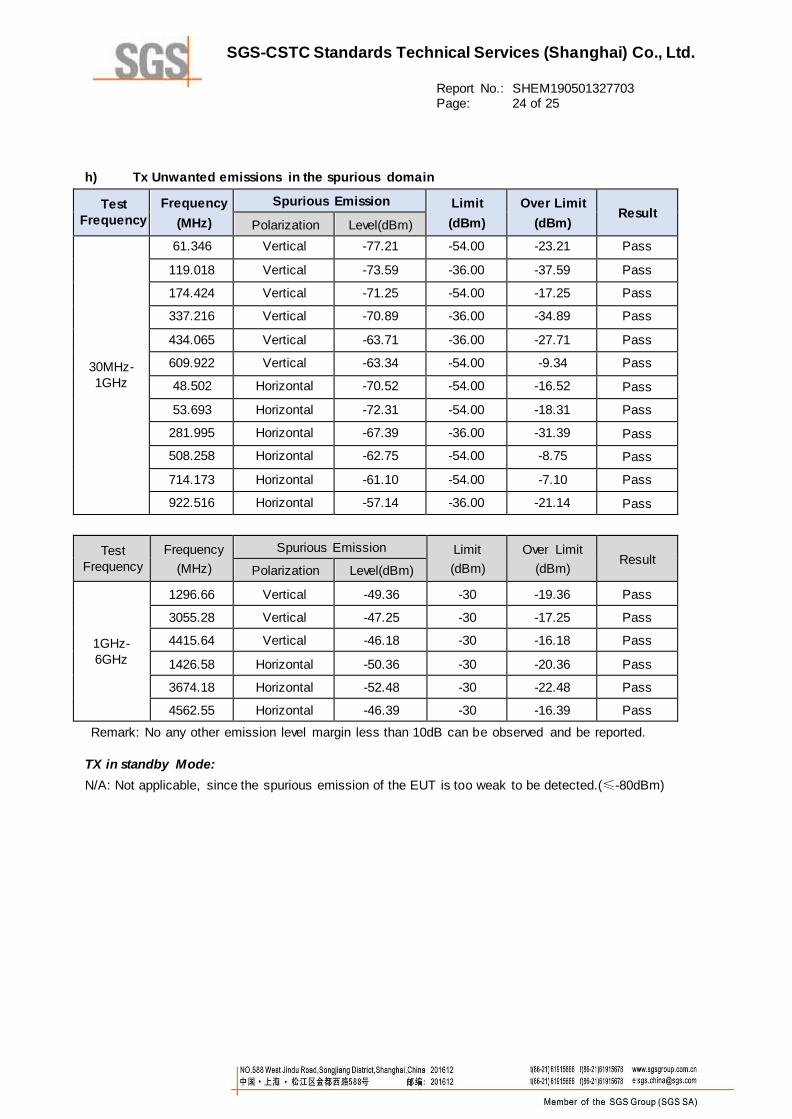
h) Tx Unwanted emissions in the spurious domain
Test
Frequency
Frequency
(MHz)
Spurious Emission Limit
(dBm)
Over Limit
(dBm) Result
Polarization Level(dBm)
30MHz-
1GHz
61.346 Vertical -77.21 -54.00 -23.21 Pass
119.018 Vertical -73.59 -36.00 -37.59 Pass
174.424 Vertical -71.25 -54.00 -17.25 Pass
337.216 Vertical -70.89 -36.00 -34.89 Pass
434.065 Vertical -63.71 -36.00 -27.71 Pass
609.922 Vertical -63.34 -54.00 -9.34 Pass
48.502 Horizontal -70.52 -54.00 -16.52 Pass
53.693 Horizontal -72.31 -54.00 -18.31 Pass
281.995 Horizontal -67.39 -36.00 -31.39 Pass
508.258 Horizontal -62.75 -54.00 -8.75 Pass
714.173 Horizontal -61.10 -54.00 -7.10 Pass
922.516 Horizontal -57.14 -36.00 -21.14 Pass
Test
Frequency
Frequency
(MHz)
Spurious Emission Limit
(dBm)
Over Limit
(dBm) Result
Polarization Level(dBm)
1GHz-
6GHz
1296.66 Vertical -49.36 -30 -19.36 Pass
3055.28 Vertical -47.25 -30 -17.25 Pass
4415.64 Vertical -46.18 -30 -16.18 Pass
1426.58 Horizontal -50.36 -30 -20.36 Pass
3674.18 Horizontal -52.48 -30 -22.48 Pass
4562.55 Horizontal -46.39 -30 -16.39 Pass
Remark: No any other emission level margin less than 10dB can be observed and be reported.
TX in standby Mode:
N/A: Not applicable, since the spurious emission of the EUT is too weak to be detected.(≤-80dBm)

SGS-CSTC Standards Technical Services (Shanghai) Co., Ltd.
Report No.: SHEM190501327703 Page: 25 of 25
i) Rx Unwanted emissions in the spurious domain
Test
Frequency
Frequency
(MHz)
Spurious Emission Limit
(dBm)
Over Limit
(dBm) Result
Polarization Level(dBm)
30MHz-
1GHz
61.995 Vertical -77.23 -57.00 -20.23 Pass
174.424 Vertical -70.15 -57.00 -13.15 Pass
330.195 Vertical -69.18 -57.00 -12.18 Pass
603.539 Vertical -61.95 -57.00 -4.95 Pass
833.317 Vertical -59.27 -57.00 -2.27 Pass
878.321 Vertical -59.64 -57.00 -2.64 Pass
39.854 Horizontal -70.66 -57.00 -13.66 Pass
48.163 Horizontal -70.35 -57.00 -13.35 Pass
277.094 Horizontal -67.25 -57.00 -10.25 Pass
508.258 Horizontal -63.25 -57.00 -6.25 Pass
716.682 Horizontal -60.36 -57.00 -3.36 Pass
912.862 Horizontal -57.58 -57.00 -0.58 Pass
Test
Frequency
Frequency
(MHz)
Spurious Emission Limit
(dBm)
Over Limit
(dBm) Result
Polarization Level(dBm)
1GHz-6GHz
1805.65 Vertical -57.25 -47 -10.25 Pass
2398.45 Vertical -59.69 -47 -12.69 Pass
3956.15 Vertical -56.47 -47 -9.47 Pass
1825.41 Horizontal -63.28 -47 -16.28 Pass
3235.08 Horizontal -58.78 -47 -11.78 Pass
4505.69 Horizontal -57.66 -47 -10.66 Pass
Remark: No any other emission level margin less than 10dB can be observed and be reported.
- End of the Report -