technical specifications andand bills of …
TRANSCRIPT
TECHNICAL SPECIFICATIONS TECHNICAL SPECIFICATIONS TECHNICAL SPECIFICATIONS TECHNICAL SPECIFICATIONS
ANDANDANDAND
BILLS OF QUANTITIESBILLS OF QUANTITIESBILLS OF QUANTITIESBILLS OF QUANTITIES
FOR FOR FOR FOR SUPPLY, INSTALLATION SUPPLY, INSTALLATION SUPPLY, INSTALLATION SUPPLY, INSTALLATION
AND COMMISSIONING OF AND COMMISSIONING OF AND COMMISSIONING OF AND COMMISSIONING OF
DATA CENTRE, UNIFIED DATA CENTRE, UNIFIED DATA CENTRE, UNIFIED DATA CENTRE, UNIFIED
COMMUNICATION NETCOMMUNICATION NETCOMMUNICATION NETCOMMUNICATION NETWORKWORKWORKWORK,,,,
AUDIO VISUAL, VIDEO AUDIO VISUAL, VIDEO AUDIO VISUAL, VIDEO AUDIO VISUAL, VIDEO
CONFERENCINGCONFERENCINGCONFERENCINGCONFERENCING, , , , QUEUEQUEUEQUEUEQUEUE
MANAGEMENT SYSTEM MANAGEMENT SYSTEM MANAGEMENT SYSTEM MANAGEMENT SYSTEM
SUPPLY, INSTALLATIONS AND COMMISSOINING OF DATA CESUPPLY, INSTALLATIONS AND COMMISSOINING OF DATA CESUPPLY, INSTALLATIONS AND COMMISSOINING OF DATA CESUPPLY, INSTALLATIONS AND COMMISSOINING OF DATA CENTRE, UNIFIED COMMUNICATION NTRE, UNIFIED COMMUNICATION NTRE, UNIFIED COMMUNICATION NTRE, UNIFIED COMMUNICATION
NETWORK, AUDIO VISUAL, VIDEO CONFERENCING, QUEUE MANAGEMENT SYSTEMNETWORK, AUDIO VISUAL, VIDEO CONFERENCING, QUEUE MANAGEMENT SYSTEMNETWORK, AUDIO VISUAL, VIDEO CONFERENCING, QUEUE MANAGEMENT SYSTEMNETWORK, AUDIO VISUAL, VIDEO CONFERENCING, QUEUE MANAGEMENT SYSTEM
TABLE OF CONTENTSTABLE OF CONTENTSTABLE OF CONTENTSTABLE OF CONTENTS
DescriptionDescriptionDescriptionDescription from Pagefrom Pagefrom Pagefrom Page
SECTION 1 SECTION 1 SECTION 1 SECTION 1 ---- PreamblePreamblePreamblePreamble
SECTION 2SECTION 2SECTION 2SECTION 2 ---- PreliminariesPreliminariesPreliminariesPreliminaries 2/12/12/12/1
SECTION 3 SECTION 3 SECTION 3 SECTION 3 ---- Part I : General SpecificPart I : General SpecificPart I : General SpecificPart I : General Specificationationationation 3/13/13/13/1
SECTION 4 SECTION 4 SECTION 4 SECTION 4 ---- Part II Part II Part II Part II ---- Particular SpecificationParticular SpecificationParticular SpecificationParticular Specification 4/1 4/1 4/1 4/1
SECTION 5 SECTION 5 SECTION 5 SECTION 5 ---- Bills of QuantitiesBills of QuantitiesBills of QuantitiesBills of Quantities
General Instructions
Particular Instructions for Pricing of Items in the Bills of Quantities 5/i
Bill of Quantities 5/1
SECTION 6 SECTION 6 SECTION 6 SECTION 6 –––– SummarySummarySummarySummary 6/16/16/16/1
SECTION 7 SECTION 7 SECTION 7 SECTION 7 ---- Data SchedulesData SchedulesData SchedulesData Schedules
PART A - General 7/1
PART B - Special Tools 7/3
PART C - Spare Parts 7/4
PART D - Contractors 7/5
PART E - Manufacturers 7/6
PART F – Deliveries
7/7
SECTION 8 SECTION 8 SECTION 8 SECTION 8 –––– Electrical Services StandardsElectrical Services StandardsElectrical Services StandardsElectrical Services Standards 8/1
SECTION 9 SECTION 9 SECTION 9 SECTION 9 –––– Tender DrawingsTender DrawingsTender DrawingsTender Drawings

Section 2Section 2Section 2Section 2
PreliminariesPreliminariesPreliminariesPreliminaries

SECTION 2SECTION 2SECTION 2SECTION 2
PRELIMINARIES COLLECTIONPRELIMINARIES COLLECTIONPRELIMINARIES COLLECTIONPRELIMINARIES COLLECTION
ITEMITEMITEMITEM AMOUNT (Kshs.)AMOUNT (Kshs.)AMOUNT (Kshs.)AMOUNT (Kshs.)
Brought Forward from Page No. 2/2
Brought Forward from Page No. 2/3
Brought Forward from Page No. 2/4
Brought Forward from Page No. 2/5
Brought Forward from Page No. 2/6
Brought Forward from Page No. 2/7
Brought Forward from Page No. 2/8
Brought Forward from Page No. 2/9
Brought Forward from Page No. 2/10
Brought Forward from Page No. 2/11
Brought Forward from Page No. 2/12
Brought Forward from Page No. 2/13
Brought Forward from Page No. 2/14
Brought Forward from Page No. 2/15
Brought Forward from Page No. 2/16
Brought Forward from Page No. 2/17
..
Brought Forward from Page No. 2/18
Brought Forward from Page No. 2/19
TOTAL OF SECTION NO. BTOTAL OF SECTION NO. BTOTAL OF SECTION NO. BTOTAL OF SECTION NO. B (Carried to Main (Carried to Main (Carried to Main (Carried to Main
Summary )Summary )Summary )Summary )

SECTION 3SECTION 3SECTION 3SECTION 3
Part I Part I Part I Part I –––– General SpecificationGeneral SpecificationGeneral SpecificationGeneral Specification

PART IPART IPART IPART I
GENERAL SPECIFICATIONGENERAL SPECIFICATIONGENERAL SPECIFICATIONGENERAL SPECIFICATION
CONTENTSCONTENTSCONTENTSCONTENTS
ItemItemItemItem DescriptionDescriptionDescriptionDescription PagePagePagePage
3333 PART I PART I PART I PART I ---- GENERAL SPEGENERAL SPEGENERAL SPEGENERAL SPECIFICATIONCIFICATIONCIFICATIONCIFICATION VIIVIIVIIVII
3.1 Programme of ICT Installations 3-2
3.2 Drawings accompanying the Tender Documents 3-2
3.3 Contract Working Drawings 3-3
3.4 Maintenance Manuals 3-4
3.5 Builder's Work and Civil Works 3-4
3.6 Commissioning of ICT Installation 3-5
3.7 Regulations and Standards 3-5
3.8 Quality of Materials 3-5
3.9 Workmanship 3-6
3.10 Setting out of work 3-7
3.11 Erection and checking of work 3-8
3.12 Site performance and acceptance tests 3-9
3.13 Test records 3-9
3.14 Dust, insect and vermin proofing 3-9
3.15 Labels 3-10
3.16 Specialist manufacturers 3-10
3.17 Interference with the existing Works 3-10
3.18 Protection of Works 3-11
3.19 Sundries 3-11
3.20 Schedules of technical data 3-11
3.21 Copies of orders 3-11

3333 PART I PART I PART I PART I ---- GENERAL SPECIFICATIONGENERAL SPECIFICATIONGENERAL SPECIFICATIONGENERAL SPECIFICATION
3.13.13.13.1 Programme for ICT InstallationsProgramme for ICT InstallationsProgramme for ICT InstallationsProgramme for ICT Installations
The Tenderer shall provide within a stipulated period of acceptance of his tender and award of
Contract, a complete programme for the electrical engineering installations to be executed
indicating the anticipated commencement and completion dates of the following activities:
(i) Placing of orders for the equipment to be incorporated in the works;
(ii) Shipment of the equipment from country of manufacture;
(iii) Delivery of the equipment to site;
(iv) Installation on site, details for all activities;
(v) Tests on Completion.
Operations shall be commenced when instructed and shall be carried forward to completion with
the greatest possible expediency, to the satisfaction of the Architect and the Engineer, in
accordance with the Programme. The Contractor’s programmes shall be agreed with the Engineer
and shall adhere fully to the requirements and timing of the agreed Main Contractor’s programme.
3.23.23.23.2 Drawings Drawings Drawings Drawings accompanying the Tender Documentsaccompanying the Tender Documentsaccompanying the Tender Documentsaccompanying the Tender Documents
The Electrical Drawings indicate generally the arrangement of the installations and are for assistance in
tendering only. The position of equipment and apparatus shown thereon are approximate only, the exact
positions, together with the actual runs of ductwork, trunking and conduit etc., will be agreed upon with
the Engineer and the Employer prior to commencement of work. It shall be deemed that the prices
entered by the Contractor include for the repositioning, of the various services, to meet the above
requirements. No claims will be entertained.
The Contractor shall satisfy himself as to the correctness of all Drawings and measurements
particularly the dimensions of the electrical installations. If the Contractor finds any discrepancy
in the Drawings or between the Drawings and the Technical Specifications or between the
electrical installations and the Drawings, he shall immediately refer the same to the Engineer
who will make a ruling on the discrepancy. Figured dimensions shall be taken in preference to
the scale mentioned on or attached to any Drawings. Details shown on Drawings shall be read
in conjunction with items included in the Technical Specifications.
The Engineer will furnish the Contractor within a reasonable time after the receipt by the
Engineer of a written request for the same, any details of which, in the opinion of the Engineer
are necessary for the execution of any part of the works. Such a request to be made only within

a reasonable time prior to the execution of such work in order to fulfil the Contract. One copy of
the Drawings, details and Technical Specifications shall be kept on the site until the completion
of the Contract and the Engineer shall at all reasonable times have access to the same. The
Contractor shall return all copies of Drawings and other relevant details to the Engineer on the
completion of the Contract.
Additional Drawings will be issued by the Contractor to the Engineer to suit the design
requirements of the works. These Drawings being issued either during or after the tender period
as may be required or necessary. These Drawings will supplement the details contained within
the Technical Specifications and Bills of Quantities and the Tenderer shall be deemed to have
taken these into account in his pricing. Where the Contractor can demonstrate that the
Drawings relate to new approved or additional items these new or additional items shall be
priced to approval in accordance with the Contract rates and prices.
3.33.33.33.3 Contract Contract Contract Contract Working DrawingsWorking DrawingsWorking DrawingsWorking Drawings
The Contractor shall prepare fully detailed Working Drawings for all equipment and
accessories required for installation under this section of the Contract. Two copies of each Drawing
shall be forwarded to the Engineer for approval and or comments. One copy will be returned stamped
"approved" or "not-approved". Where Drawings require further information and/or modifications to
meet the comments made by the Engineer they shall be re-submitted, again in duplicate, for approval.
When Drawings have been approved two further copies shall be forwarded to the Engineer, together
with copies to the Architect, Site and the Employer.
Drawings, and, where relevant, calculations in respect of the following shall be prepared by
the Contractor and submitted to the Services Engineer for his approval commencing within ten (10)
days from acceptance of the tender:
(a) Technical literature for all the services;
(b) Shop drawings.
All drawings shall be to scale and fully detailed with all the important dimensions shown and the
construction of key components indicated.
During progress of the building works, the Contractor shall make all necessary checks on site
to ascertain that the various services can be installed as specified and shown on the approved
Drawings.
Where such works cannot be so installed, this must be immediately brought to the notice of the
Engineer and Architect prior to the progress of such works.

The Engineer, in conjunction with the Architect and the Employer, will check and return the
Drawings submitted for approval within a reasonable period, but in any case not exceeding
fourteen (14) days from receipt of the Drawings.
The layouts of plant and equipment are for general guidance only. The Contractor shall assess the
requirements and prepare a plant layout for approval within twenty one (21) days, the required
liaison being maintained with other specialists, such that an agreed layout is submitted for
approval.
3.43.43.43.4 Maintenance ManualsMaintenance ManualsMaintenance ManualsMaintenance Manuals
At the start of the defects liability period, the Contractor shall hand over to the Engineer, four sets
of maintenance and operations manuals for each plant and equipment installed. These manuals
shall be in English and shall be fully illustrated.
3.53.53.53.5 Builder's Work and Civil WorksBuilder's Work and Civil WorksBuilder's Work and Civil WorksBuilder's Work and Civil Works
Builder's Work and Civil Works that are incidental to this section of the Contract such as cutting
of holes in walls and floors, provisions of foundations for the plant and machinery, shall be the
responsibility of the Main Contractor. The Contractor shall be fully responsible for the
preparation of all such details that relate to such works, the details being subject to approval by
the Architect and Engineer prior to submission to the Main Contractor for action. Other items
such as fixing of brackets, cables and ductwork and trenching, making good etc. shall be carried
out by the Contractor to suit the installation of all the services.
It is the Contractor's sole responsibility to ensure that all holes and chases are in the required
position and that any additional ducts, holes and chases necessary for erection of the
installations in situ concrete walls, floor slabs etc., are included in the early stages of
construction as appropriate.
The Contractor shall furnish the Engineer, Architect and Main Contractor with all the necessary
information including position of foundations, brackets and fixings and shall ensure that such
works are performed in accordance with available information.
The Contractor shall include in his tender all supports, fixings, plugging of holes in walls, ceilings
and floors to facilitate the fixing of the pipework, accessories, and all other portions of the
plumbing, drainage and fire fighting installations. Any purpose-made fixing brackets shall also
be provided and installed by the Contractor, including escutcheon plates and the like.
The Contractor shall supply and install approved pipework support brackets and hangers. It
shall be deemed that prices include for any special requirements and that the Contractor has visited
the site during the tender period to ascertain all details.
The Contractor shall pay particular attention to the fixing and alignment of items. All items shall be
installed square, true and perpendicular to floors i.e. as shown on Drawings and as may be required at

site to the Engineers approval.
3.63.63.63.6 Commissioning of the Commissioning of the Commissioning of the Commissioning of the ICT InstallationsICT InstallationsICT InstallationsICT Installations
The Contractor shall instruct the Employer’s Maintenance Engineer or his representative on the
operation and maintenance of the various components forming the electrical installation and shall
provide drawings, diagrams and manuals to ensure the Maintenance Engineer or his
representative is completely conversant with such installations.
The Contractor shall ensure that the services installations are left in complete safe working order
and operating to the satisfaction of the Engineer.
3.73.73.73.7 Regulations and StandardsRegulations and StandardsRegulations and StandardsRegulations and Standards
The Installations must be carried out strictly in accordance with the following documents:
(i) ANSI/TIA/EIA-942 Data Centre Standards
(ii) ISO 27001 Standards
(iii) Relevant International Standards;
(iv) Current Regulations and by-laws of KPLC;
(v) Regulations and by-laws of the Ministry of Energy;
(vi) Nairobi City Council (NCC) By-Laws;
(vii) Current Regulations of Communication Authority of Kenya
(viii) By-laws of the Electricity Regulatory Commission (ERC);
(ix) Current Regulations of Kenya Airports Authority;
(x) Any other duly constituted authorities’ regulations having jurisdiction over the Works;
(xi) Water Supply and Sewerage Authority’s Regulations;
(xii) The Specification and accompanying documentation and Drawings;
The Contractor shall undertake all modifications demanded by the authorities in order to comply
with the regulations, and produce all certificates, if any, for the authorities at no extra charge.
3.83.83.83.8 Quality of MaterialsQuality of MaterialsQuality of MaterialsQuality of Materials
All materials, fittings and accessories are to be new and in accordance with the requirements of
the current rules and regulations where such exist, and with the relevant international
standards.
Uniformity of type and manufacture of fittings and accessories is to be as far as practicable
preserved throughout the whole Works.

Wherever the term 'similar to' is used in these Technical Specifications in reference to any item,
the word will be understood to mean type and quality of the equipment and not preference.
Where particular manufacturers only are specified herein no alternative makes will be
considered without good reasons.
All materials shall be of good quality, suitable for the purpose specified, and to the approval of
the Engineer.
3.93.93.93.9 WorkmanshipWorkmanshipWorkmanshipWorkmanship
The Tenderer shall take into consideration, when pricing his tender, that there will be other
specialists working alongside him. Any disruptions to the existing services must therefore be kept
to a minimum, and in this respect the Contractor shall include in his prices for carrying out Works
outside normal working hours as may be directed by the Engineer. No claim will be entertained
where abnormal working hours are required to meet this requirement and completion of the works
within the specified Contract period.
The Contractor shall be fully responsible for co-ordination of installation of all services. For all
services involving ducted wiring, such wiring shall be capable of future addition or maintenance.
The Contractor shall be deemed to have included in his tender prices for relocating switches,
terminal points, ductwork, outlets and fixtures in positions and/or locations at least one metre in
any direction from the positions indicated on the Drawings. Within these limits no variations in
the Contract sum will be made unless the work has already been executed in accordance with
previously approved Working Drawings.
Only qualified and certified persons shall be allowed to carry out installation work. The Works shall
be performed in a neat and workmanlike manner.
The Contractor shall take every precaution to avoid damage to the existing property including
roads, paved walkways, grassed areas, landscaping, cables, drains and other services, and he
will be held responsible for and shall make good all such damage at his own expense to the
satisfaction of the Engineer.
The Contractor will be responsible for the exact runs and placing of pipework, conduit, boxes,
ductwork and accessories that are to be cast in concrete, ceilings, floors, walls, columns and
beams, and for the proper fixing of the pipework and accessories to the shuttering and the steel
reinforcement work.

Where ductwork is to concealed, the pipes etc shall be in an exact position relative to the
finished plaster or such other finishes as may be applied to enable adequate cover to be applied.
Where services are run above the false ceilings the Contractor shall ensure that access to all
services is readily available such that future maintenance can be carried out without difficulty.
Full details shall be included on the Working Drawings such that the Engineer can give
consideration to the Contractor's proposals.
3.103.103.103.10 Setting out of workSetting out of workSetting out of workSetting out of work
The Contractor will be responsible for laying out his work and shall obtain all the necessary
information as may be required to carry out the work. Such information shall be obtained sufficiently in
advance to avoid any possibility of delay to the Works as a whole.
The Contractor shall be fully responsible, and shall seek, the details of all work being carried out
by the various trades on Site, particularly where such trades may interfere with each other, or
where co-ordination is necessary. No claims for extra costs will be entertained arising from
omissions, oversight, or neglect in this regard.
In advance of the delivery of the plant and equipment, the Contractor shall arrange for the supply
of all-necessary foundation bolts, templates, nuts, plates, sleeves, anchorages, etc., as required
and as may be directed by the Engineer.
3.113.113.113.11 Erection and checking of workErection and checking of workErection and checking of workErection and checking of work
The Contractor shall provide, and be solely responsible for, all skilled and unskilled labour, tools,
lifting tackle and other equipment required for handling of plant and equipment when transporting
to Site, within the Site and during erection.
All erection works shall be subject to approval by the Engineer.
All parts shall pass such tests as required by the Engineer to prove compliance with the
Contract irrespective of any tests which may already have been carried out at the Manufacturer's
Works. In particular all electrical pressure tests made at the Manufacturer's Works shall be
repeated at voltages approved by the Engineer.
The Contractor shall supply and install all supports, fixings, brackets and similar items as may be
necessary for the completion of the installation of the services as specified and as shown on the
Drawings.

3.123.123.123.12 Site performance and acceptance testsSite performance and acceptance testsSite performance and acceptance testsSite performance and acceptance tests
The Contractor shall give notice of the date of the specified tests to be performed on completion
of installation. The notice shall be made in writing to the Engineer at least five days to the date of
the specified tests. Unless otherwise agreed the tests shall take place within seven days of the
stated date or on such day or days as the Engineer shall in writing notify the Contractor in
writing. The tests shall be carried out under normal working conditions to the satisfaction of the
Engineer and shall extend over such continuous periods as he may direct.
All skilled labour, supervision, apparatus, fuel and instruments required for carrying out the tests
will be the responsibility and at the expense of the Contractor. The accuracy of the instruments
shall be demonstrated if required. The Contractor shall ensure that test instruments are in good
working condition and have been calibrated by an authorised agent.
If any part of the plant or equipment fails to pass the specified tests, further tests of the said
part shall, if required by the Engineer, be repeated. The Contractor shall, without delay, put in
hand such modifications as found necessary so as to meet the requirements of the Contract
and any expense which the Client may have incurred by reason of such further tests shall be
deducted from the Contractor’s Contract price.
Each completed system within the installation shall be tested as a whole under operating
conditions to ensure that each component functions correctly in conjunction with the rest of the
system.
3.133.133.133.13 Test recordsTest recordsTest recordsTest records
The Contractor shall make the necessary records of all the tests carried out, and when the tests
have been successfully completed he shall provide the Engineer with test records and reports in a
format to be agreed.
3.143.143.143.14 Dust, insect and vermin proofingDust, insect and vermin proofingDust, insect and vermin proofingDust, insect and vermin proofing
All equipment, likely to be affected by ingress of dust, shall be effectively dust proofed and
vermin proofed where no protection is afforded in its normal manufactured form. All materials
used shall be in general resistant to attack by insects, micro-organisms or other fauna or flora.
Materials used for such protection shall be to the approval of the Architect and Engineer.
3.153.153.153.15 LabelsLabelsLabelsLabels
All items of electrical plant, Sub-main distribution boards, etc. shall be neatly and clearly labelled
externally with identification marks corresponding with those on Drawings or in Technical
Specifications. Final details shall be agreed upon by the Contractor and the Engineer.
Identification labels shall be of laminated plastic material engraved, black on white, with no less
than 6mm "Lino" style letters and shall be fixed on or adjacent to all items by means of at least
two brass screws or to the approval of the Engineer. Self-adhesive labels shall not be permitted.
All labels/plates shall be in English.
3.163.163.163.16 Specialist manufacturersSpecialist manufacturersSpecialist manufacturersSpecialist manufacturers
Where specialists are not nominated by the Employer, the Contractor shall appoint specialist
manufacturers and suitable specialists for any sections of the Works described herein in which he
is not himself an experienced, recognized and approved specialist.
The Tenderer shall, on submission of his tender, indicate the names of all proposed specialist
manufacturers and specialists, together with the precise sections of the Works for which each will be
responsible. The Contractor may be required to seek alternative manufacturers or Contractors or to
accept specialists nominated by the Employer; it shall be deemed that the prices entered in the tender
include for this requirement. For plant and equipment supplied by suppliers other than the Contractor,
the Contractor will be required to furnish an agreement between himself and the supplier stating that
he is authorised by the supplier to deal in the plant and equipment and that he is authorised to stock
the necessary spare parts or that the Employer will be authorised to revert to the supplier in the event
of breakdown of the plant or equipment.
The Contractor shall allow in his prices for phasing his work to meet the requirements of the
other specialists, and for varying his programme or otherwise, to comply with the erection
programme of such specialist. No additional costs will be allowed to the Contractor for any
disruptions to his programme, or otherwise, in his compliance with the above requirements.
3.173.173.173.17 Interference with the existing WorksInterference with the existing WorksInterference with the existing WorksInterference with the existing Works
The Contractor shall not interfere in any way with any existing works whether the property of the
Employer or of a third party and whether the position of such works is indicated to the Contractor
by the Engineer or not. The exception being where such interference is specifically described as
part of the Works either in the Contract or in any instruction from the Engineer.
3.183.183.183.18 Protection of WorksProtection of WorksProtection of WorksProtection of Works
The Contractor shall carefully protect from injury by weather all Work and materials which may be
affected thereby and allow in his prices for all dams, pumping, shoring, temporary drains, sumps
etc. necessary for the purpose. The Contractor shall clear away and make good at his own cost to
the satisfaction of the Engineer all damage caused thereby.
3.193.193.193.19 SundriesSundriesSundriesSundries
The necessary holding down bolts, supporting brackets and templates, guards and screens, locks,
piping, conduits, lamps and other requisite sundries whether specified in detail or not shall be
provided, under the Contract and it shall be deemed that the Contractor's prices, rates and the like
include for all such items.
3.203.203.203.20 Schedules of technical dataSchedules of technical dataSchedules of technical dataSchedules of technical data
Where included in the Tender Documents, all Tenderers shall complete Schedules of technical
data; otherwise the Tender may not receive full consideration, and will be liable to rejection.
3.213.213.213.21 Copies of ordersCopies of ordersCopies of ordersCopies of orders
Copies of all orders for major items of plant, equipment and materials places with suppliers shall be
provided in triplicate to the Engineer.

SECTION 4SECTION 4SECTION 4SECTION 4
Part II Part II Part II Part II –––– Particular SpecificationParticular SpecificationParticular SpecificationParticular Specification

PART IIPART IIPART IIPART II
PARTICULAR SPECIFICATIONS FORPARTICULAR SPECIFICATIONS FORPARTICULAR SPECIFICATIONS FORPARTICULAR SPECIFICATIONS FOR
SUPPLY, INSTALLATIONS AND COMMISSOINING OF DATA CENTRE, UNIFIED COMMUNICATION SUPPLY, INSTALLATIONS AND COMMISSOINING OF DATA CENTRE, UNIFIED COMMUNICATION SUPPLY, INSTALLATIONS AND COMMISSOINING OF DATA CENTRE, UNIFIED COMMUNICATION SUPPLY, INSTALLATIONS AND COMMISSOINING OF DATA CENTRE, UNIFIED COMMUNICATION
NETWORK, AUDIO VISUAL, VIDEO CONFERENCING, QUEUE MANAGEMENT SYSTEMNETWORK, AUDIO VISUAL, VIDEO CONFERENCING, QUEUE MANAGEMENT SYSTEMNETWORK, AUDIO VISUAL, VIDEO CONFERENCING, QUEUE MANAGEMENT SYSTEMNETWORK, AUDIO VISUAL, VIDEO CONFERENCING, QUEUE MANAGEMENT SYSTEM
TABLE OF CONTABLE OF CONTABLE OF CONTABLE OF CONTENTSTENTSTENTSTENTS
ItemItemItemItem DescriptionDescriptionDescriptionDescription PagePagePagePage
4444 PART 2 PART 2 PART 2 PART 2 ---- PARTICULAR SPECIFICATIONPARTICULAR SPECIFICATIONPARTICULAR SPECIFICATIONPARTICULAR SPECIFICATION
4.1 Extent of installation
4.2 Modulaer Data centre
Certification requirement
Installation & environment requirements
Overall modular requirement
Active network
Unified communication telephony
Open DNS
Perimeter security and Display tools
4.3 Monitoring solution
Network performance monitoring
Server & application monitoring
Help desk solution
4.4 Queue Management system
4.5 Video conference solution
General
System Design
Mandatory Requirements

PART 2 PART 2 PART 2 PART 2 ---- PARTICULAR SPECIFICATIONPARTICULAR SPECIFICATIONPARTICULAR SPECIFICATIONPARTICULAR SPECIFICATION
4.1 4.1 4.1 4.1 Extent of installationExtent of installationExtent of installationExtent of installation
The Contractor shall carry out all the necessary works for successful installation of the
equipment’s and infrastructure as described and set out in this section of the Technical
Specification, Bills of Quantities, other sections of the equipment documents and accompanying
Drawings in accordance with the General and Standard Practice herewith.
The Works, the major elements of which are scheduled below, includes “but is not limited to” but is not limited to” but is not limited to” but is not limited to”
supply of all labour, material, equipment and components necessary for complete installation
and setting out work in respect of the entire infrastructure and services requirements within the
proposed development and rendering it in complete working condition in respect of but not
limited to the following installations:
New Installations: Supply, Installation, testing and commissioning of the following installations
to the satisfaction of the Services Engineer:
• Modular data center;
• Active network;
• Unified communication;
• Open DNS
• Perimeter Security Tools and systems – Firewall;
• Server & Software;
• Office 365 + End Point Security;
• Monitoring tools solution;
• Audio Visual system;
• Video conferencing system;
• Queue management system.
• Access Control and Security Solution;
In general, the installations shall be concealed in heavy gauge PVC conduits except in areas
where surface installation is necessary. In such cases, installation will be carried out in trunking,
galvanized steel conduit or cable trays (by others) as indicated on the Drawings.

4.2 Modular Data CentreModular Data CentreModular Data CentreModular Data Centre
The modular data centre facilities include the power supply and distribution system, cooling
system, cabinet system, monitoring system and Fire suppression system. This chapter
describes the functional requirements for the equipment. Bidders are to provide compliance
response to each category.
• Certification RequirementsCertification RequirementsCertification RequirementsCertification Requirements
NNNN
oooo
FeaturesFeaturesFeaturesFeatures MinimumMinimumMinimumMinimum RequirementsRequirementsRequirementsRequirements Bidder’s Bidder’s Bidder’s Bidder’s
ResponseResponseResponseResponse
1. Supplier certification Supplier certification Supplier certification Supplier certification
requirementsrequirementsrequirementsrequirements
• The supplier must be certified by the following
certification systems and provide the certificates:
• Computer Information System Integration
Qualification Certificate (Class 1)
• ISO 9001/TL9000
• ISO 14001
• ISO IEC_27001
• OHSAS 18001
Testing equipment
requirements • The supplier should have state-authorized labs that
have been certified by the following organizations
and provide the certificates:
• State-level lab accreditation organization: CNAS,
A2LA
• Industrial or national appointed accreditation or
certification organizations: ISTA, FCC, IC, VCCI
• Third-party test and certification organizations: UL,
MET, CETECOM, ITS, TUV RH, TUV PS
Product certification
requirements
• Air conditioner: CE, SASO certificates obtained;
RoHS, REACH, reports obtained
• Battery cabinet: CE, RoHS, REACH, certificates
obtained
• Converged cabinet: CE, RoHS, REACH, SASO
certificates obtained

• Installation and Environment RequirementsInstallation and Environment RequirementsInstallation and Environment RequirementsInstallation and Environment Requirements
NNNN
oooo
FeatuFeatuFeatuFeaturesresresres MinimumMinimumMinimumMinimum RequirementsRequirementsRequirementsRequirements Bidder’s Bidder’s Bidder’s Bidder’s
ResponseResponseResponseResponse
1. Environmental Environmental Environmental Environmental
adaptability adaptability adaptability adaptability
requirementsrequirementsrequirementsrequirements
• The modular data center should apply to
the outdoor environment with the air
temperature range of –20°C to +45°C, the
relative humidity range of 5% to 95%, and
the altitude range of 0 m to 4000 m.
Power supply
requirements
• The equipment room should provide the
redundant power supplies of 400/415 V
AC, 50 & 60 Hz, 3Ph+N+PE.
Installation
requirements
• The module should support single-row
deployment to efficiently use the
equipment room space and can be
installed on the concrete floor or ESD
floor.
• Floor height requirements; The modular
data center can be installed without a
raised floor and meets the requirements
for the 2.6 m net height
• Overall Modular RequireOverall Modular RequireOverall Modular RequireOverall Modular Requirements ments ments ments
The data centre uses the modular architecture design and features the cold aisle
containment. A single module should integrate the cabinet system, power supply and
distribution system, cooling system, management system, and generic cabling system. The
module provides space for up to eight cabinets. Each cabinet has the maximum rated power of
7 kW, and the total IT load is 15 kW at most.

NNNN
oooo
FeaturesFeaturesFeaturesFeatures MinimumMinimumMinimumMinimum RequirementsRequirementsRequirementsRequirements Bidder’s Bidder’s Bidder’s Bidder’s
ResponseResponseResponseResponse
1. Modular
Requirements Tier requirement: Uptime Tier2
Surge protection level: CLASS II/C, In 20kA, Imax
40kA, 8/20 μs
Waterproof and dustproof level: IP20
Certification requirement: Main components
should be CE certified.
Configuration requirement: aisle containment,
rack-mounted variable-frequency air
conditioner, easy maintenance, less footprint,
high integration, and high energy efficiency
Rack-mounted UPS in N+1 mode.
Installation and maintenance requirement: The
module can be installed on the concrete floor
(raised floor not required) in a building and
can be maintained from the front and rear.
Backup time requirement: 30 min backup time is
supported.
Battery deployment mode requirement: The battery
rack can be deployed outside the module.
Cooling mode: Air cooled rack-mounted air
conditioners are supported.
Monitoring function: A single module can be
remotely monitored over the web user
interface (WebUI). Alarms can be sent by the
short message service (SMS). The mobile
APP can be used for mobile operation and
maintenance (O&M).

Cabling mode: Cables can be routed from the top or
bottom.
Containment flexibility requirement: Cold aisle
containment can be used.
Computational fluid dynamics (CFD) simulation
report: The supplier should provide the CFD
heat analysis and simulation report to
optimize the system design.
Modular design: Modular design is adopted for
power distribution equipment, UPS,
monitoring equipment, and air conditioner
indoor units to facilitate maintenance.
Environment adaptability requirement: The
deployment space should meet the
requirement for 2.6 m net floor height.
To guarantee high quality delivering, the vender
should acquire the service certification from
OEM factory and evidence should be
provided.
• Active NetworkActive NetworkActive NetworkActive Network
a.a.a.a. Edge FirewallEdge FirewallEdge FirewallEdge Firewall
NNNN
OOOO
FeaturesFeaturesFeaturesFeatures MiMiMiMinimumnimumnimumnimum RequirementsRequirementsRequirementsRequirements Bidder’s Bidder’s Bidder’s Bidder’s
ResponseResponseResponseResponse
1.1.1.1. Gigabit Ethernet Gigabit Ethernet Gigabit Ethernet Gigabit Ethernet
InterfaceInterfaceInterfaceInterface
• provides 8 Gigabit Ethernet
interfaces,80GB SSD
Stateful inspection Stateful inspection Stateful inspection Stateful inspection
throughput throughput throughput throughput
(multiprotocol)(multiprotocol)(multiprotocol)(multiprotocol)
• 500 Mbps
Maximum 3DES/AES Maximum 3DES/AES Maximum 3DES/AES Maximum 3DES/AES
VPN throughputVPN throughputVPN throughputVPN throughput
• 175 Mbps
Virtual interfaces Virtual interfaces Virtual interfaces Virtual interfaces
(VLANs(VLANs(VLANs(VLANs))))
• 50
High AvailabilityHigh AvailabilityHigh AvailabilityHigh Availability
• high availability to help ensure business
continuity
MemoryMemoryMemoryMemory
• 8 GB

Power (AC or DC)Power (AC or DC)Power (AC or DC)Power (AC or DC)
• AC
IPSEC VPNIPSEC VPNIPSEC VPNIPSEC VPN
• supports up to 100 IPsec VPN peers,
50,000 concurrent connections and 1
Gbps throughput.
Integrated policy Integrated policy Integrated policy Integrated policy
management ovemanagement ovemanagement ovemanagement over r r r
multiple security multiple security multiple security multiple security
functions functions functions functions
• Configures firewall access, application
control, threat prevention, URL filtering,
and advanced malware protection
settings in a single policy
• Eases policy administration, reduces
errors, and promotes consistency
• Enables a single policy to be deployed to
multiple security solutions
Application visibility Application visibility Application visibility Application visibility
and control and control and control and control
• Further reduces threats to your network
with precise control of more than 4000
commercial applications
• Uses the open-source standard Open App
ID for detailed identification and control
over custom applications
Reporting Reporting Reporting Reporting
• Provides the visibility you need through
customizable dashboards with custom
and template-based reports
• Delivers comprehensive alerts and
reports for both general and focused
information
• Displays event and contextual information
in hyperlinked tables, graphs, and charts
for easy-to-use analysis
• Monitors network behavior and
performance to identify anomalies and
maintain system health
SecuritySecuritySecuritySecurity
• Intrusion Prevention, Application and
Visibility, Malware Protection and URL
Filtering capability.
•
QuantityQuantityQuantityQuantity
• Two Firewalls for high availability to cater
for Business Continuity

b.b.b.b. Core SwitchCore SwitchCore SwitchCore Switch
NNNN
oooo
FeaturesFeaturesFeaturesFeatures MinimumMinimumMinimumMinimum RequirementsRequirementsRequirementsRequirements Bidder’s Bidder’s Bidder’s Bidder’s
ResponseResponseResponseResponse
1. InterfacesInterfacesInterfacesInterfaces
• 16-port 10Gig switch
Switching capacitySwitching capacitySwitching capacitySwitching capacity
• Up to 240 Gbps
Forwarding rateForwarding rateForwarding rateForwarding rate
• Up to 360 Mpps
DRAMDRAMDRAMDRAM
• 16 G
Chassis with 2 power Chassis with 2 power Chassis with 2 power Chassis with 2 power
supplies and builtsupplies and builtsupplies and builtsupplies and built----In In In In
fanfanfanfan
• 23.6 lb (10.7 kg)
Operating Operating Operating Operating
• 32° to 104°F (0° to 40°C)
MemoryMemoryMemoryMemory • Has a 4-core x86, 2.4-GHz CPU, 16-GB
DDR4 memory, and 16-GB internal
storage.
Forwarding rate Forwarding rate Forwarding rate Forwarding rate
• Up to 360 Mpps
•
Total number of MAC Total number of MAC Total number of MAC Total number of MAC
addresses addresses addresses addresses
• Up to 64,000*
QoS ACL scale QoS ACL scale QoS ACL scale QoS ACL scale
• Up to 18000*
•
VLAN IDs VLAN IDs VLAN IDs VLAN IDs
• 4000
Jumbo frame Jumbo frame Jumbo frame Jumbo frame • 9198 bytes
Altitude Altitude Altitude Altitude • Operation up to 13,000 feet at 40°C
c.c.c.c. Access Switch Access Switch Access Switch Access Switch
NNNN
OOOO
FeaturesFeaturesFeaturesFeatures MinimumMinimumMinimumMinimum RequirementsRequirementsRequirementsRequirements Bidder’s Bidder’s Bidder’s Bidder’s
ResponseResponseResponseResponse
1. Total 10/100/1000 or Total 10/100/1000 or Total 10/100/1000 or Total 10/100/1000 or
Multigigabit copper Multigigabit copper Multigigabit copper Multigigabit copper
portsportsportsports
• 48-port PoE+
Default AC power Default AC power Default AC power Default AC power
supplysupplysupplysupply
Available PoE powerAvailable PoE powerAvailable PoE powerAvailable PoE power
• 715W AC
• 437W

Switching capacitySwitching capacitySwitching capacitySwitching capacity • 256 Gbps on 48-port Gigabit Ethernet
model
Stacking bandwidthStacking bandwidthStacking bandwidthStacking bandwidth • 480 Gbps
Total number of MAC Total number of MAC Total number of MAC Total number of MAC
addressesaddressesaddressesaddresses
• 32,000
Packet buffer per SKUPacket buffer per SKUPacket buffer per SKUPacket buffer per SKU • 16 MB buffer for 24- or 48-port Gigabit
Ethernet models
Jumbo framesJumbo framesJumbo framesJumbo frames • 9198 bytes
Layer 3 FeaturesLayer 3 FeaturesLayer 3 FeaturesLayer 3 Features • Switch should have Layer 3 features
Intent based and SD Intent based and SD Intent based and SD Intent based and SD
Access FeatureAccess FeatureAccess FeatureAccess Feature
• The switches should support SD Access
QuantityQuantityQuantityQuantity • Seven in number
d.d.d.d. Wireless Controller Wireless Controller Wireless Controller Wireless Controller
NNNN
OOOO
FeaturesFeaturesFeaturesFeatures MinimumMinimumMinimumMinimum RequirementsRequirementsRequirementsRequirements Bidder’s Bidder’s Bidder’s Bidder’s
ResponseResponseResponseResponse
1. TechnologyTechnologyTechnologyTechnology
• Multigigabit Ethernet technology to
support next-generation 802.11ac Wave 2
deployments using existing cabling
infrastructure.
Scalability and Scalability and Scalability and Scalability and
performance performance performance performance
Optimized to enable 802.11ac Wave 2 next-
generation networks, supporting:
• 4-Gbps throughput
• 150 access points
• 3000 clients
• 1x Multigigabit Ethernet interface (up to 5
Gigabit Ethernet), + 4x 1 Gigabit Ethernet
• 4096 VLANs
Flexibility and ease of Flexibility and ease of Flexibility and ease of Flexibility and ease of
deployment deployment deployment deployment
• Only 10-in. (25-cm) depth to fit nicely in
reduced-depth cabinet or desktop
deployments
• Quiet and fanless operation for cabinet or
desktop (up to 86°F [30°C] ambient)
deployment. The fans are used by the
controller only under certain conditions
• For quick and easy deployment, access
points can be connected directly to the
controller via two Power Over Ethernet
(PoE) ports

RF management RF management RF management RF management
• Proactively identifies and mitigates signal
interference for better performance
Comprehensive endComprehensive endComprehensive endComprehensive end----totototo----
end security end security end security end security
• Offers Control and Provisioning of
Wireless Access Points (CAPWAP)-
compliant Datagram Transport Layer
Security (DTLS) encryption on the control
plane between access points and
controllers across remote WAN links
• Management frame protection detects
malicious users and alerts network
administrators
• Rogue detection for Payment Card
Industry (PCI) compliance
• Rogue access point detection and
detection of denial-of-service attacks
e.e.e.e. Access Point Access Point Access Point Access Point
NNNN
OOOO
FeaturesFeaturesFeaturesFeatures MinimumMinimumMinimumMinimum RequirementsRequirementsRequirementsRequirements Bidder’s Bidder’s Bidder’s Bidder’s
ResponseResponseResponseResponse
1. TechnologyTechnologyTechnologyTechnology
• delivers new 802.11ac Wave 2 standard
• 802.11ac Beamforming
• 20-, 40-, 80, 160-MHz channels
• PHY data rates up to 5.2 Gbps
• Packet aggregation: A-MPDU (Tx/Rx), A-
MSDU (Tx/Rx)
• 802.11 DFS
• 1024 MB DRAM
• 256 MB flash
AntennaAntennaAntennaAntenna
• provides internal antenna and E
regulatory domain.
MIMMIMMIMMIMOOOO
• 4x4 MU-MIMO with three spatial streams

• Unified Communication telephonyUnified Communication telephonyUnified Communication telephonyUnified Communication telephony
a.a.a.a. Systems Requirement Systems Requirement Systems Requirement Systems Requirement
NNNN
OOOO
FeaturesFeaturesFeaturesFeatures MinimumMinimumMinimumMinimum RequirementsRequirementsRequirementsRequirements Bidder’s Bidder’s Bidder’s Bidder’s
ResponseResponseResponseResponse
1. TechnologyTechnologyTechnologyTechnology
• Technology is DDR4 SDRAM
ProcessorProcessorProcessorProcessor
• 1 processor(s) installed
• 2 processor(s) supported
RAMRAMRAMRAM
• 48GB installed RAM
•
MemoryMemoryMemoryMemory
• 13MB installed cache
• 300GB Hot-swap hard drive
SizeSizeSizeSize
• 1U Rackmount
AppsAppsAppsApps
• Supports four collaboration application
options plus one for provisioning in a
single virtualized server platform
Maximum number of Maximum number of Maximum number of Maximum number of
users users users users
• 1000
Number of devices Number of devices Number of devices Number of devices
supported supported supported supported
• 1200
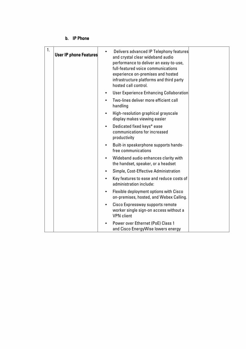
b.b.b.b. IP Phone IP Phone IP Phone IP Phone
1. User IP phone FeaturesUser IP phone FeaturesUser IP phone FeaturesUser IP phone Features
• Delivers advanced IP Telephony features
and crystal clear wideband audio
performance to deliver an easy-to-use,
full-featured voice communications
experience on-premises and hosted
infrastructure platforms and third party
hosted call control.
• User Experience Enhancing Collaboration
• Two-lines deliver more efficient call
handling
• High-resolution graphical grayscale
display makes viewing easier
• Dedicated fixed keys* ease
communications for increased
productivity
• Built-in speakerphone supports hands-
free communications
• Wideband audio enhances clarity with
the handset, speaker, or a headset
• Simple, Cost-Effective Administration
• Key features to ease and reduce costs of
administration include:
• Flexible deployment options with Cisco
on-premises, hosted, and Webex Calling.
• Cisco Expressway supports remote
worker single sign-on access without a
VPN client
• Power over Ethernet (PoE) Class 1
and Cisco EnergyWise lowers energy
costs

c.c.c.c. Voice Gateway RouterVoice Gateway RouterVoice Gateway RouterVoice Gateway Router
NNNN
OOOO
FeaturesFeaturesFeaturesFeatures MinimumMinimumMinimumMinimum RequirementsRequirementsRequirementsRequirements Bidder’s Bidder’s Bidder’s Bidder’s
ResponseResponseResponseResponse
1. Aggregate ThroughputAggregate ThroughputAggregate ThroughputAggregate Throughput
• 50 Mbps to 100 Mbps
Total onboard WAN or Total onboard WAN or Total onboard WAN or Total onboard WAN or
LAN 10/100/1000 portsLAN 10/100/1000 portsLAN 10/100/1000 portsLAN 10/100/1000 ports
• 2
•
RJRJRJRJ----45454545----based portsbased portsbased portsbased ports
• 2
SFPSFPSFPSFP----based portsbased portsbased portsbased ports
• 1
NIM (Network Interface NIM (Network Interface NIM (Network Interface NIM (Network Interface
Modules) slotsModules) slotsModules) slotsModules) slots
• 1
MemoryMemoryMemoryMemory
• 4 GB (default) / 8 GB (maximum)
Aggregate Throughput Aggregate Throughput Aggregate Throughput Aggregate Throughput
(Performance License) (Performance License) (Performance License) (Performance License)
• 100 to 300 Mbps
LicenseLicenseLicenseLicense
• Unified Communication License
ChannelChannelChannelChannel
• 256-channel DSP module
CardCardCardCard
• 4-port Network Interface Module - FXO
(Universal)
Conference Phone Conference Phone Conference Phone Conference Phone
FeaturesFeaturesFeaturesFeatures
• Superior wide band acoustics with the
first two-element speaker in a
conference phone; this feature allows the
phone to capture the full voice spectrum
without having to compromise with a
single-element speaker
• Expanded room coverage with support
for daisy chaining two units
• Support for optional DECT wireless
extension microphone: sold separately
• Session Initiation Protocol (SIP) signaling
• Device authentication and signaling
encryption using Transport Layer
Security (TLS) with Advanced Encryption
Standard 128 (AES-128)
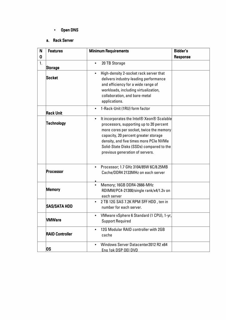
• Open DNSOpen DNSOpen DNSOpen DNS
a.a.a.a. Rack ServerRack ServerRack ServerRack Server
NNNN
OOOO
FeaturesFeaturesFeaturesFeatures MinimumMinimumMinimumMinimum RequirementsRequirementsRequirementsRequirements Bidder’s Bidder’s Bidder’s Bidder’s
ResponseResponseResponseResponse
1. StorageStorageStorageStorage
• 20 TB Storage
SocketSocketSocketSocket
• High-density 2-socket rack server that
delivers industry-leading performance
and efficiency for a wide range of
workloads, including virtualization,
collaboration, and bare-metal
applications.
Rack UnitRack UnitRack UnitRack Unit
• 1-Rack-Unit (1RU) form factor
•
TechnologyTechnologyTechnologyTechnology
• It incorporates the Intel® Xeon® Scalable
processors, supporting up to 20 percent
more cores per socket, twice the memory
capacity, 20 percent greater storage
density, and five times more PCIe NVMe
Solid-State Disks (SSDs) compared to the
previous generation of servers.
PPPProcessorrocessorrocessorrocessor
• Processor; 1.7 GHz 3104/85W 6C/8.25MB
Cache/DDR4 2133MHz on each server
•
MemoryMemoryMemoryMemory
• Memory; 16GB DDR4-2666-MHz
RDIMM/PC4-21300/single rank/x4/1.2v on
each server
SAS/SATA HDDSAS/SATA HDDSAS/SATA HDDSAS/SATA HDD
• 2 TB 12G SAS 7.2K RPM SFF HDD , ten in
number for each server.
VMWVMWVMWVMWareareareare
• VMware vSphere 6 Standard (1 CPU), 1-yr,
Support Required
RAID ControllerRAID ControllerRAID ControllerRAID Controller
• 12G Modular RAID controller with 2GB
cache
OS OS OS OS
• Windows Server Datacenter2012 R2 x64
Eng 1pk DSP OEI DVD
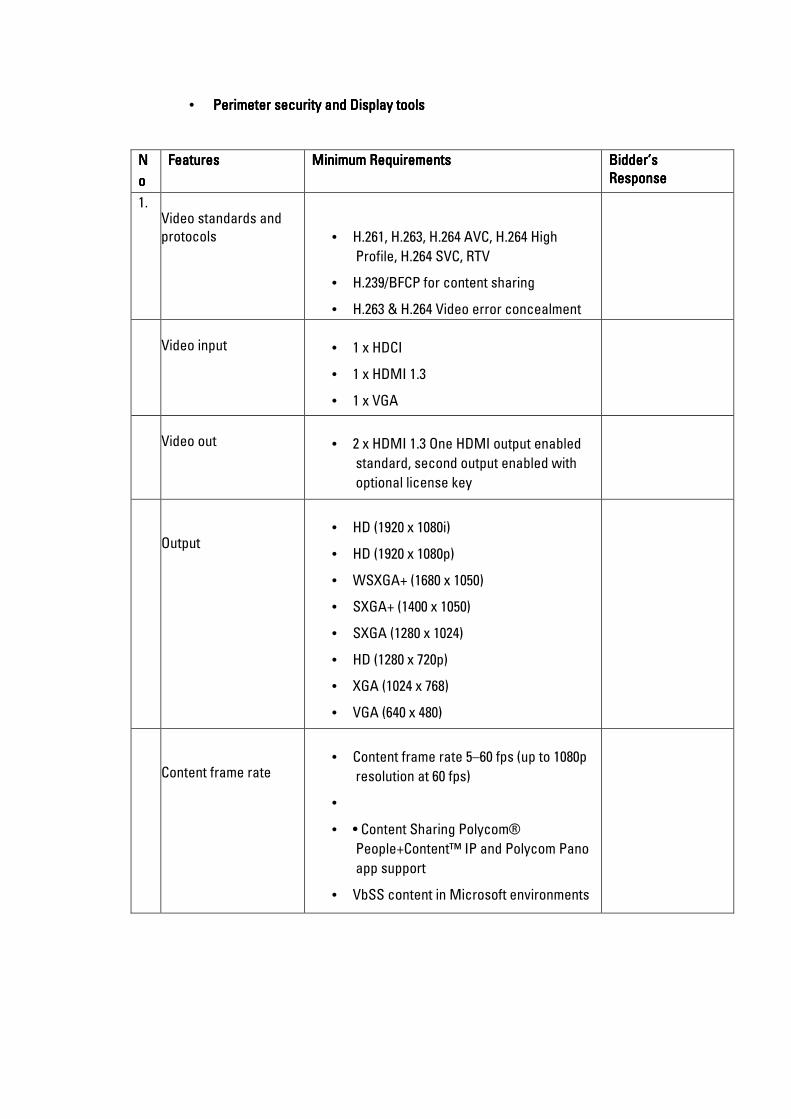
• Perimeter security and Display toolsPerimeter security and Display toolsPerimeter security and Display toolsPerimeter security and Display tools
NNNN
oooo
FeaturesFeaturesFeaturesFeatures MiniMiniMiniMinimum Requirementsmum Requirementsmum Requirementsmum Requirements Bidder’s Bidder’s Bidder’s Bidder’s
ResponseResponseResponseResponse
1. Video standards and
protocols
• H.261, H.263, H.264 AVC, H.264 High
Profile, H.264 SVC, RTV
• H.239/BFCP for content sharing
• H.263 & H.264 Video error concealment
Video input
• 1 x HDCI
• 1 x HDMI 1.3
• 1 x VGA
Video out
• 2 x HDMI 1.3 One HDMI output enabled
standard, second output enabled with
optional license key
Output
• HD (1920 x 1080i)
• HD (1920 x 1080p)
• WSXGA+ (1680 x 1050)
• SXGA+ (1400 x 1050)
• SXGA (1280 x 1024)
• HD (1280 x 720p)
• XGA (1024 x 768)
• VGA (640 x 480)
Content frame rate
• Content frame rate 5–60 fps (up to 1080p
resolution at 60 fps)
•
• • Content Sharing Polycom®
People+Content™ IP and Polycom Pano
app support
• VbSS content in Microsoft environments
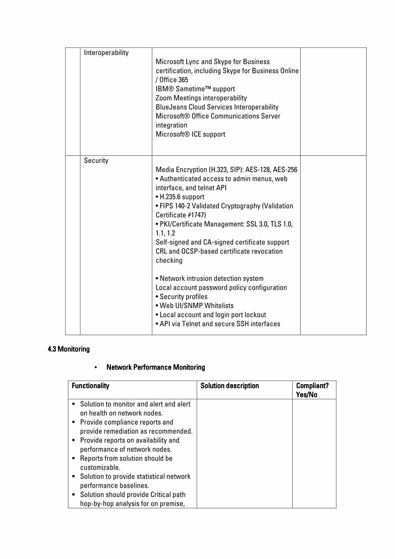
Interoperability
Microsoft Lync and Skype for Business
certification, including Skype for Business Online
/ Office 365
IBM® Sametime™ support
Zoom Meetings interoperability
BlueJeans Cloud Services Interoperability
Microsoft® Office Communications Server
integration
Microsoft® ICE support
Security
Media Encryption (H.323, SIP): AES-128, AES-256
• Authenticated access to admin menus, web
interface, and telnet API
• H.235.6 support
• FIPS 140-2 Validated Cryptography (Validation
Certificate #1747)
• PKI/Certificate Management: SSL 3.0, TLS 1.0,
1.1, 1.2
Self-signed and CA-signed certificate support
CRL and OCSP-based certificate revocation
checking
• Network intrusion detection system
Local account password policy configuration
• Security profiles
• Web UI/SNMP Whitelists
• Local account and login port lockout
• API via Telnet and secure SSH interfaces
4.3 4.3 4.3 4.3 Monitoring Monitoring Monitoring Monitoring
• Network Performance Monitoring Network Performance Monitoring Network Performance Monitoring Network Performance Monitoring
FunctionalityFunctionalityFunctionalityFunctionality Solution descriptionSolution descriptionSolution descriptionSolution description Compliant? Compliant? Compliant? Compliant?
Yes/NoYes/NoYes/NoYes/No
Solution to monitor and alert and alert
on health on network nodes.
Provide compliance reports and
provide remediation as recommended.
Provide reports on availability and
performance of network nodes.
Reports from solution should be
customizable.
Solution to provide statistical network
performance baselines.
Solution should provide Critical path
hop-by-hop analysis for on premise,

hybrid, and cloud services.
Solutions should be able to Cross-
stack network data correlation for
acceleration of problem identification
Capability to manage and monitor
wireless nodes.
Collect and report on inventory from
network nodes
• Server and Application MonitoringServer and Application MonitoringServer and Application MonitoringServer and Application Monitoring
Solution to manage applications
running in the cloud
Provide capability to monitor Internal
and External performance of websites.
Provide performance counters of
virtual environment
Provide performance statistics of
servers as well as capacity planning
features of hardware
Provide application dependency
mapping features
Provide for self-healing features of
server applications
Provide capacity planning and
performance of virtual environment
servers and virtual machine sprawl
control.
Provide capability to monitor VDI
environment with statistics on
performance and configuration
management capabilities, alerting,
remediation, and chargeback
automation
Collect and report on inventory from
server nodes
Monitor application stack issues that
may affect the application
performance in storage environments
Capable of providing complete
visibility of Office 365 environment,
with management and reporting tool
• Help DeskHelp DeskHelp DeskHelp Desk SolutionSolutionSolutionSolution
Solution should Simplify and
streamline IT help desk processes
from service request creation to
resolution
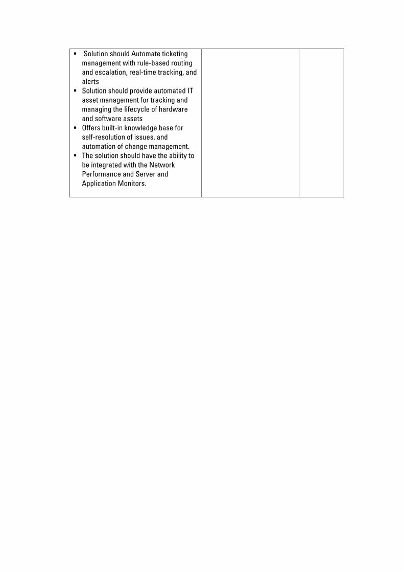
Solution should Automate ticketing
management with rule-based routing
and escalation, real-time tracking, and
alerts
Solution should provide automated IT
asset management for tracking and
managing the lifecycle of hardware
and software assets
Offers built-in knowledge base for
self-resolution of issues, and
automation of change management.
The solution should have the ability to
be integrated with the Network
Performance and Server and
Application Monitors.

4.4 4.4 4.4 4.4 Queue Management system Queue Management system Queue Management system Queue Management system
Minimum Requirements Minimum Requirements Minimum Requirements Minimum Requirements ComplianceComplianceComplianceCompliance
Yes/NoYes/NoYes/NoYes/No
Comments Comments Comments Comments
Ticket Dispenser
Ticket Dispenser: The Queue
Management system should come with
a ticket dispenser unit to facilitate for
customers to take a ticket
Multiple categories/reason for visiting:
Customers should be able to select
more than 1 reason for visiting the
branch at the touch of a button in the
ticket dispensing unit.
The Kiosk should be capable of running
promotional media contents when it is
not serving any customer service
requests.
In case of automated process flows
where the customer journey from one
counter to another is known for a
completion of a service, the system
should be capable of automatically
routing customer accordingly for
providing service efficiency.
The Kiosk screen contents should be
managed from a central location for
easy dissemination into the branches.
The services priorities and its changes
should be centrally manageable.
Run adverts on Ticket Dispenser:
Screen-saver mode on the
Ticket Dispenser/ QMS Customer
interface should show eye-catching,
dynamic promotional media to captivate
the audience. The system should have
the capability to change the
promotional media remotely
Processor System
Operating System: Android OS, V4.04
(ICS)
CPU: Dual Core 1.0 GHz
Power Requirement
Power Input: ~100-240v (AC) 50/60 Hz
Power Consumption: 100 Watt
Display
Display Type: 17 inches TFT, 16.1M
colors

Resolution: 1280 x 1024 pixels (96ppi)
Touch Screen: Capacitive Touch
Screen 3M Branch
Mechanical
Dimensions:
1400 (H) x 478 (L) x 480 (W) mm (without
packaging)
16500 (H) X 673 (L) X 600 (W) mm (with
packaging)
Material: Metal
Main Screen Display Unit:
The system to provide a Screen Display
Unit that will display current ticket
number to be served along with
respective service counter in large font.
The service should be flexible enough
to be used with an existing LCD or
Plasma TV with PC.
Along with the ticket numbers the
display screen should also display
client advertisements on one portion of
the screen.
Counter Display Unit:
Counter display unit must be capable of
displaying ticket numbers, counter
numbers, directional information and
also promotional messaging. The CDU
directs waiting customers to the right
counter and can also be used to convey
short instructional messages. The CDU
should be flexible enough to be Wall
mounted, desk fixed or suspended from
the ceiling. Should be activated when
the service representative hits the next
button. When the counter is inactive,
CDU displays “CLOSED” or any other
customized message.
Agent Interface
This software should have the following
features:
Should be a web based interface
Employee logs in through username and
password.
Employee calls for next customer
through a mouse click
The software also shows statistical
data about queues and customers.
The software shows employee

performance as easy-to-read color
indicators showing the employee
performance compared to average and
target performance.
The employee can transfer the
customer to another service queue.
The transfers should be available to be
a service queue change or a counter
change.
The transfer reason should be marked
so the next calling Teller (Employee) is
able to understand why the customer is
being routed to him/her.
The employee can send a customer to a
“wait status” and call him again from
the wait status.
The employee can chat with the branch
manager though the software.
It should be possible to add
tags/comments or additional
information eg Names, tel phone
number etc for a customer to be viewed
by the Teller (Employee) later or while
transferring the customer to another
counter.
The Teller (Employee) should be able to
random call a customer from the
waiting queues in order to serve the
customer superseding the usual queue
calling sequence.
The system should enable the Teller to
allocate the total service time into
various sub-services and mark them
accordingly for evaluating his/her
overall efficiency.
The system should provide Tellers a
leverage to perform backend activities
apart from their designated customer
service duties such as performing back
office functions and taking breaks.
The system should have an effective
alert mechanism for updating the Teller
if they are sitting idle for too long or has
a customer in wait for too long.
The system should provide auto logging
off facilities in case the Teller forgets to
shut off his logged in session.
The system should be able to repeat the
customer calling sound automatically
so that incase a customer misses a
calling sound, they can respond to the

second call.
The system should allow Tellers to mark
a customer as a no show in case he/she
fails to respond to multiple sound calls
for reaching at a particular counter.
Reporting software
Should be a web based application
accessible on any browser
Enables branch manager to monitor,
control and configure the branch.
Viewing the status of each counter
such as:
Which employee is working on which
counter?
What the employee stats are such as
logged in time, idle time, total customer
service time and backend activity
(breaks) time?
Which customer is being served on
which counter including customer data.
The time since the customer has been
called for service.
Any moment the service time on a
certain counter exceeds a certain limit
(pre-configured for each service), the
system provides an alert to the branch
manager (the counter appears in a
different color).
The branch manager can send and
receive messages from employees
(chatting)
The branch manager is able to view
statistics about the current status of the
branch including number of waiting
customers for each service.
The branch manager is able to view the
list of waiting customers and can
transfer them to other services by
assessing the branch workload and
efficiency stats.
The branch manager can assign
services to counters or tellers, and
these changes must be reflected on the
fly.
View various performance reports and
dashboards about employees and the
branch as a whole.
It is mobile & Tablet responsive,
adjusted to any type of screen size.
Manager is able to create his/her own

dashboards components.
Manager should be able to change the
Service Quality percentage
dynamically.
Manager is able to filter a ticket, a
teller, a customer name, etc and only
such filter should be shown on the
dashboard.
Manager is able to change the priority
calling and calling profile of tellers on
the fly without having to restart the
system.
Training
The offered solution should include
Administration training covering the
following topics:
Customization and Integration
Installation, operation &
Troubleshooting
Documentation
The offered solution should include a
soft copy of Administrator and User
Guides provided on CD’s.
Warranty and Support
The offered system should include one
year warranty and support from the
date of final acceptance for each
branch.

SECTION 5SECTION 5SECTION 5SECTION 5
Bill Of Quantities Bill Of Quantities Bill Of Quantities Bill Of Quantities
A.A.A.A. General InstructionsGeneral InstructionsGeneral InstructionsGeneral Instructions
B.B.B.B. PartiPartiPartiParticular Instructions for Pricing of Items in the Bills of Quantitiescular Instructions for Pricing of Items in the Bills of Quantitiescular Instructions for Pricing of Items in the Bills of Quantitiescular Instructions for Pricing of Items in the Bills of Quantities
C.C.C.C. Bill of Quantities Bill of Quantities Bill of Quantities Bill of Quantities

A.A.A.A. General InstructionsGeneral InstructionsGeneral InstructionsGeneral Instructions
5.1 5.1 5.1 5.1 Detailed requirements Detailed requirements Detailed requirements Detailed requirements ---- Smart Small Modular Data Centre SolutionSmart Small Modular Data Centre SolutionSmart Small Modular Data Centre SolutionSmart Small Modular Data Centre Solution
5.15.15.15.1.1.1.1.1 OverviewOverviewOverviewOverview
This document is provided by KPPF to illustrate the technical specifications for the modular data
centre project. It provides guidelines for interested bidders to compile the project technical proposal
and offer a quotation. In the technical proposal, interested bidders must specify and address each
technology and project requirement specified in this document.
Interested bidders must keep all internal documents and technical documents and information
provided by KPPF confidential.
5.1.25.1.25.1.25.1.2 Project BackgroundProject BackgroundProject BackgroundProject Background
The following table analyses the data centre requirements in the project.
No.No.No.No. IT Service IT Service IT Service IT Service
Requirement Requirement Requirement Requirement
ItemItemItemItem
Power Power Power Power
InputInputInputInput
IT IT IT IT
Cabinet/Rack Cabinet/Rack Cabinet/Rack Cabinet/Rack
(Set)(Set)(Set)(Set)
UPS UPS UPS UPS
ConfigurationConfigurationConfigurationConfiguration
Air Conditioner Air Conditioner Air Conditioner Air Conditioner
ConfigurationConfigurationConfigurationConfiguration
IT Load IT Load IT Load IT Load
(kW)(kW)(kW)(kW)
1 DC Sizing Dual
inputs
4 N +1 N +1 20
Total: Dual
inputs
4 N +1 N +1 20
5.1.3 5.1.3 5.1.3 5.1.3 Related StandardsRelated StandardsRelated StandardsRelated Standards
The products (including software and hardware) provided by the Bidder must comply with technical
standards, which include but are not limited to the following:
1. Code for design of electronic information system room (GB50174-2008)
2. Code for construction and acceptance of electronic information system room (GB50462-
2008)
3. ISO27001/ ISO20000
4. ASHARE TC9.9 2009
5. Information security technology - Disaster recovery specifications for information systems
(2007)
6. Standard for design of intelligent building (GB/T50314-2006)
7. Code for acceptance of quality of intelligent building (GB 50339-2003)
8. Code for design of electric power supply systems (GB50052-95)
9. Low voltage distribution design specifications (GB50054-95)
10. Code for engineering acceptance of generic cabling system (GB 50312-2007)
11. Code for engineering design of generic cabling system (GB 50311-2007)
12. Communication chamber electrostatic protective general rules (YD/T754-95)
13. Regulations for electromagnetic radiation protection (GB8702-88)
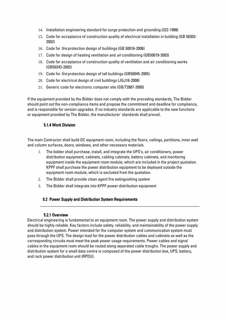
14. Installation engineering standard for surge protection and grounding (322-1998)
15. Code for acceptance of construction quality of electrical installation in building (GB 50303-
2002)
16. Code for fire protection design of buildings (GB 50016-2006)
17. Code for design of heating ventilation and air conditioning (GB50019-2003)
18. Code for acceptance of construction quality of ventilation and air conditioning works
(GB50243-2002)
19. Code for fire protection design of tall buildings (GB50045-2005)
20. Code for electrical design of civil buildings (JGJ16-2008)
21. Generic code for electronic computer site (GB/T2887-2000)
If the equipment provided by the Bidder does not comply with the preceding standards, The Bidder
should point out the non-compliance items and propose the commitment and deadline for compliance,
and is responsible for version upgrades. If no industry standards are applicable to the new functions
or equipment provided by The Bidder, the manufacturer' standards shall prevail.
5.1.4 5.1.4 5.1.4 5.1.4 Work DivisionWork DivisionWork DivisionWork Division
The main Contractor shall build DC equipment room, including the floors, ceilings, partitions, inner wall
and column surfaces, doors, windows, and other necessary materials.
1. The bidder shall purchase, install, and integrate the UPS’s, air conditioners, power
distribution equipment, cabinets, cabling cabinets, battery cabinets, and monitoring
equipment inside the equipment room module, which are included in the project quotation.
KPPF shall purchase the power distribution equipment to be deployed outside the
equipment room module, which is excluded from the quotation.
2. The Bidder shall provide clean agent fire extinguishing system
3. The Bidder shall integrate into KPPF power distribution equipment
5.2 5.2 5.2 5.2 Power Supply and Distribution System RequirementsPower Supply and Distribution System RequirementsPower Supply and Distribution System RequirementsPower Supply and Distribution System Requirements
5.2.1 5.2.1 5.2.1 5.2.1 OverviewOverviewOverviewOverview
Electrical engineering is fundamental to an equipment room. The power supply and distribution system
should be highly reliable. Key factors include safety, reliability, and maintainability of the power supply
and distribution system. Power intended for the computer system and communication system must
pass through the UPS. The design load for the power distribution cables and cabinets as well as the
corresponding circuits must meet the peak power usage requirements. Power cables and signal
cables in the equipment room should be routed along separated cable troughs. The power supply and
distribution system for a small data centre is composed of the power distribution box, UPS, battery,
and rack power distribution unit (RPDU).

5.2.2 5.2.2 5.2.2 5.2.2 Design ScopeDesign ScopeDesign ScopeDesign Scope
The design scope for this phase of the project is power distribution in the KPPF equipment room
module.
UPS power supply and distribution system design
Power supply and distribution for the air conditioning system
The power for equipment except the preceding items and outside the equipment room is not
considered in this phase.
The power supply and distribution system should use the N+1 architecture and meet the tier 1 or tier 2
requirements or GB 50174 class C requirements. The 400/415 V AC, 50/60 Hz, 3Ph+N+PE power
distribution solution is supported.
5.2.3 5.2.3 5.2.3 5.2.3 UPS UPS UPS UPS
The UPS provides uninterruptible power for IT loads in the small data center by means of batteries
when the external primary power supply fails.
The UPS for the small data center must meet the following requirements:
The UPS whose rated capacity is 20 kVA, can be installed in the 19-inch rack, and occupies only
3 U heights.
The UPS rated input voltage is 400/415 V, 50/60 Hz, 3Ph+N+PE.
Wide input voltage range: 138–485 V AC
The UPS provides high efficiency up to 95% in online mode.
The UPS has strong overload capacity and continues running for 60s when overloaded by 125%.
The UPS provides RS485 communications port for easily monitoring its parameters and status.
CategoryCategoryCategoryCategory ItemItemItemItem 20 kVA20 kVA20 kVA20 kVA
Input Input voltage
range
80–280 V AC, single-phase
When the voltage is 80–176 V AC, the load power is linearly
derated to 40%–100%.
138–485 V AC, three-phase
When the voltage is 138–305 V AC, the load power is linearly
derated to 40%–100%.
Rated input
voltage
AC/ 400 V AC /415 V AC (three-phase)
Input frequency
range
40–70 Hz
Output Rated capacity 20 kVA
Rated voltage 400/ 415 V AC; three-phase output; a voltage system can be
selected by setting a voltage level over the LCD.
Power factor 0.9
Max. efficiency 95%
Overload
capacity
In normal mode, when the UPS is overloaded to a range between
105% and 125%, the UPS transfers to the bypass mode in 5

CategoryCategoryCategoryCategory ItemItemItemItem 20 kVA20 kVA20 kVA20 kVA
minutes if the bypass is normal or disconnects the power
output if the bypass is abnormal.
In normal mode, when the UPS is overloaded to a range between
125% and 150%, the UPS transfers to the bypass mode in 1
minute if the bypass is normal or disconnects the power output
if the bypass is abnormal.
In normal mode, when the UPS is overloaded to more than 150%,
the UPS transfers to the bypass mode in 0.1 second if the
bypass is normal, or disconnects the power output if the
bypass is abnormal.
Structure Dimensions (H x
W x D)
130 mm x 430 mm x 757 mm
Installation
mode
Rack-mounted
Surge
protection
IEC/EN60240-2
IEC/EN61000-4-5
YD/T1095-2000 YD/T944-2007
The AC input meets class D surge protection requirements
(differential mode and common mode: 5 kA, 8/20 μs).
Environment Port type Dry contact/USB/Modbus/SNMP
Operating
temperature
0–40°C
Relative
humidity
0%–95% RH (non-condensing)
Altitude < 1000 m (derated when the altitude is between 1000 m and 4000
m. For derating data, refer to the IEC62040-3.)
Storage and
transportation
temperature
–40°C to +70°C (battery pack: –20°C to +40°C)
5.2.4 5.2.4 5.2.4 5.2.4 Power Distribution BoxPower Distribution BoxPower Distribution BoxPower Distribution Box
Type of power distribution equipment: ATSE power distribution module, UPS input and output
power distribution module, indicator power distribution module
Installation mode: rack-mounted
Electrical performance
The power distribution box contains the UPS input, UPS output, UPS maintenance bypass
switch, and surge protection switch. The 6 U high power distribution module should
provide at least 14 IT outputs.

The class C SPD is deployed in standard configuration. A surge protection switch should be
installed before the SPD, and a micro switch with the surge protection switch or SPD
fault indicator should be used to remotely monitor the SPD status.
Application environment
Operating temperature: 0°C to +40°C
Operating humidity: ≤ 95% RH
Operating altitude: 2000 meters without derating
5.2.55.2.55.2.55.2.5 RPDU RPDU RPDU RPDU
Electrical performance
Single-phase 230 V AC input voltage, 50/60 Hz
Single-phase of the RPDU
Input: junction box input or standard IEC60309 three-core plug input
Output: C13/C19 standard socket, circuit breaker protection supported by the RPDU of 32 A
or higher current
Application environment
Operating temperature: 0°C to +40°C
Operating humidity: ≤ 95% RH
Operating altitude: 2000 meters without derating
ItemItemItemItem SpecSpecSpecSpecificationsificationsificationsifications
Input voltage range 176–264 V AC
Input voltage 230 V AC
Input current 32 A
Number of inputs Single
Output power distribution specifications 20 x C13 + 4 x C19
Dimensions (L x W x D) 1732 mm x 50 mm x 44.5 mm
Net weight 2.49 kg
5.3 5.3 5.3 5.3 CCCCooling System Requirementsooling System Requirementsooling System Requirementsooling System Requirements
5.3.1 5.3.1 5.3.1 5.3.1 Technical Requirements for InTechnical Requirements for InTechnical Requirements for InTechnical Requirements for In----row Precision Air Conditionersrow Precision Air Conditionersrow Precision Air Conditionersrow Precision Air Conditioners
The air conditioners should feature efficient cooling, effective energy saving, high reliability, wide
working conditions, wide power range, high compatibility, intelligent monitoring, and easy
maintenance.

5.3.2 5.3.2 5.3.2 5.3.2 High Energy EfficiencyHigh Energy EfficiencyHigh Energy EfficiencyHigh Energy Efficiency
Name brand DC inverter compressors with high energy efficiency can achieve 20%–100% steeples
speed adjustment to provide cooling capacity on demand, thereby greatly reducing energy
consumption.
Six EC fans in the indoor unit use the horizontal air supply mode for racks. 30%–100% steeples
fan speed adjustment is supported, which enables precise control over the supply air
temperature and direction, thereby reducing energy consumption.
Optimal system configurations and efficient refrigeration coil pipes ensure efficient heat
exchange.
The variable-frequency temperature control algorithm enables quick response to load changes
and precise temperature control to conserve energy.
Fans support variable-frequency start, which lowers the start current and prevents shock on the
power grid and other electrified equipment.
A wet film humidifier consumes more than 90% less energy than a conventional humidifier
because energy consumption of a wet film humidifier comes only from the water pump.
The air conditioners are connected over FE ports and networked through the MAC protocol bus
to achieve teamwork control, which effectively saves energy.
5.3.3 5.3.3 5.3.3 5.3.3 High ReliabilityHigh ReliabilityHigh ReliabilityHigh Reliability
The DC variable-frequency air conditioner greatly reduces the number of startup and shutdown
times, reducing component failures and extending the lifespan of key components.
The electronic expansion valve is used, allowing rapid and precise adjustment of the refrigerant
volume based on the temperature and humidity requirements and improving system
stability. A backup power module is provided to close the electronic expansion valve when
the system experiences a power failure.
The Positive Temperature Coefficient (PTC) electric heater provides dual protection functions:
automatic reset and auto-recovery disabling.
The air conditioner is designed for non-condensation at low loads to maintain the humidity in
cold aisles below 80% at low loads (10% load at least) in a high-humidity environment.
The air conditioner features 6 kV surge protection design, providing high surge protection
reliability.
5.3.4 5.3.4 5.3.4 5.3.4 High CompatibilityHigh CompatibilityHigh CompatibilityHigh Compatibility
The air conditioner can be rack-mounted, which considerably decreases the cooling system
footprint as it occupies only 11 U high space.
Both the refrigerant pipes and water pipes can be routed from the top or bottom.
Heating and humidification functions are optional.
5.3.5 5.3.5 5.3.5 5.3.5 Wide Power RangeWide Power RangeWide Power RangeWide Power Range
Adaptability to multiple power systems:
System supply voltage 220–240 V AC, L+N+PE, 50 Hz
Voltage range: 198–264 V AC
Frequency range: 47–53 Hz
5.3.6 5.3.6 5.3.6 5.3.6 Intelligent MonitoringIntelligent MonitoringIntelligent MonitoringIntelligent Monitoring
Users can monitor and configure parameters for the cooling system on the monitoring unit.
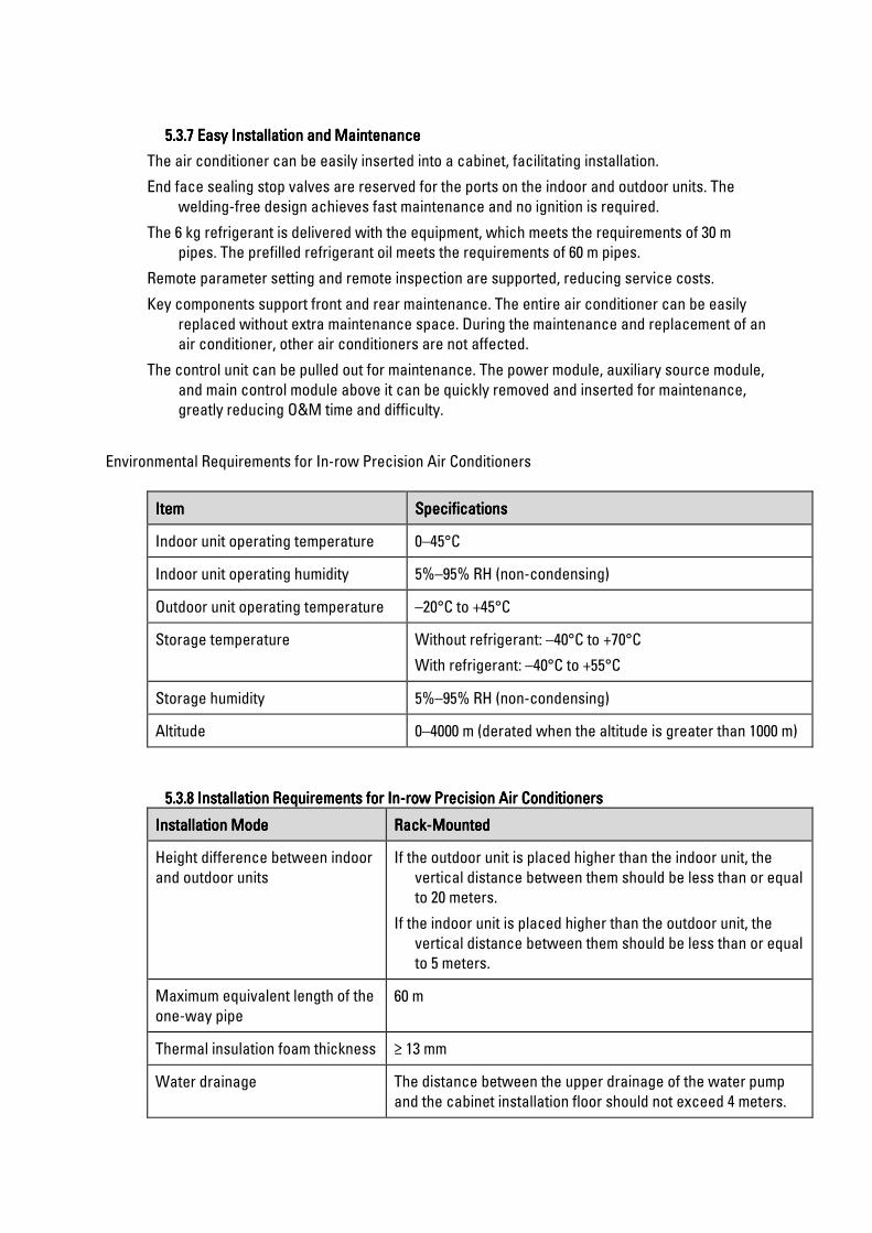
5.3.7 5.3.7 5.3.7 5.3.7 Easy Installation and MaintenanceEasy Installation and MaintenanceEasy Installation and MaintenanceEasy Installation and Maintenance
The air conditioner can be easily inserted into a cabinet, facilitating installation.
End face sealing stop valves are reserved for the ports on the indoor and outdoor units. The
welding-free design achieves fast maintenance and no ignition is required.
The 6 kg refrigerant is delivered with the equipment, which meets the requirements of 30 m
pipes. The prefilled refrigerant oil meets the requirements of 60 m pipes.
Remote parameter setting and remote inspection are supported, reducing service costs.
Key components support front and rear maintenance. The entire air conditioner can be easily
replaced without extra maintenance space. During the maintenance and replacement of an
air conditioner, other air conditioners are not affected.
The control unit can be pulled out for maintenance. The power module, auxiliary source module,
and main control module above it can be quickly removed and inserted for maintenance,
greatly reducing O&M time and difficulty.
Environmental Requirements for In-row Precision Air Conditioners
ItemItemItemItem SpecificationsSpecificationsSpecificationsSpecifications
Indoor unit operating temperature 0–45°C
Indoor unit operating humidity 5%–95% RH (non-condensing)
Outdoor unit operating temperature –20°C to +45°C
Storage temperature Without refrigerant: –40°C to +70°C
With refrigerant: –40°C to +55°C
Storage humidity 5%–95% RH (non-condensing)
Altitude 0–4000 m (derated when the altitude is greater than 1000 m)
5.3.8 5.3.8 5.3.8 5.3.8 Installation Requirements for InInstallation Requirements for InInstallation Requirements for InInstallation Requirements for In----row Precision Air Conditionersrow Precision Air Conditionersrow Precision Air Conditionersrow Precision Air Conditioners
Installation ModeInstallation ModeInstallation ModeInstallation Mode RackRackRackRack----MountedMountedMountedMounted
Height difference between indoor
and outdoor units
If the outdoor unit is placed higher than the indoor unit, the
vertical distance between them should be less than or equal
to 20 meters.
If the indoor unit is placed higher than the outdoor unit, the
vertical distance between them should be less than or equal
to 5 meters.
Maximum equivalent length of the
one-way pipe
60 m
Thermal insulation foam thickness ≥ 13 mm
Water drainage The distance between the upper drainage of the water pump
and the cabinet installation floor should not exceed 4 meters.

5.3.9 5.3.9 5.3.9 5.3.9 MaiMaiMaiMain Technical Specifications for Inn Technical Specifications for Inn Technical Specifications for Inn Technical Specifications for In----row Precision Air Conditionersrow Precision Air Conditionersrow Precision Air Conditionersrow Precision Air Conditioners
The following table lists the main technical specifications for air conditioners.
Air conditioner technical specifications
SpecificationsSpecificationsSpecificationsSpecifications 11 kW
Indoor fan typeIndoor fan typeIndoor fan typeIndoor fan type EC fan
Total cooling capacitTotal cooling capacitTotal cooling capacitTotal cooling capacityyyy ≥ 11 kW
Sensible cooling capacitySensible cooling capacitySensible cooling capacitySensible cooling capacity ≥ 11 kW
Sensible heat ratioSensible heat ratioSensible heat ratioSensible heat ratio 1
Air volumeAir volumeAir volumeAir volume ≥ 2600 m3/h
Indoor unit installation modeIndoor unit installation modeIndoor unit installation modeIndoor unit installation mode Rack-mounted
Outdoor unit installation modeOutdoor unit installation modeOutdoor unit installation modeOutdoor unit installation mode Wall/floor-mounted
Heating capacity (optional)Heating capacity (optional)Heating capacity (optional)Heating capacity (optional) ≥ 3kW
The cooling capacity is measured at the indoor inlet air temperature 37.8°C, relative
humidity 20%, and condensing temperature 35°C.
5.4 5.4 5.4 5.4 Cabinet System RequirementsCabinet System RequirementsCabinet System RequirementsCabinet System Requirements
5.4.1 5.4.1 5.4.1 5.4.1 Aisle Containment SystemAisle Containment SystemAisle Containment SystemAisle Containment System
The depth of a contained aisle should be no more than 250 mm.
Hot aisle: The front door is a single-swing double-layered glass door that prevents
condensation.
Cold aisle: The front door is a perforated door.
5.4.2 5.4.2 5.4.2 5.4.2 Cabinet SystemCabinet SystemCabinet SystemCabinet System
Cabinets are necessary facilities in a data centre. They provide an appropriate operating
environment for accommodating and interconnecting equipment.
The cabinets must provide the following features:
The ventilation rate of the perforated door is greater than or equal to 70%.
Two power distribution units (PDUs) can be vertically installed at the rear of the cabinet.
The position of each U is marked on the vertical mounting bars.
The front and rear doors are locked and can be unlocked only with dedicated keys.
The total depth of the cabinet and aisle is 1350 mm at most.
ItemItemItemItem Technical SpecificationsTechnical SpecificationsTechnical SpecificationsTechnical Specifications
Dimensions
(H x W x D)
IT cabinet: 2000 mm x 600 mm x 1350 mm
Battery cabinet (deployed inside the aisle containment): 2000 mm x 600 mm x

ItemItemItemItem Technical SpecificationsTechnical SpecificationsTechnical SpecificationsTechnical Specifications
1350 mm
Battery cabinet (deployed outside the aisle containment): 2000 mm x 600 mm x
1100 mm/1200 mm
Network cabinet: 2000 mm x 600 mm/800 mm x 1350 mm
Color Black
Material High-intensity class A carbon cold rolled steel sheet and zinc-coated steel
sheet
Air channel Front and rear air channels
Installation space Each cabinet provides 42 U available space.
The distance between the front and rear mounting bars can be adjusted by a
step of 25 mm. Positions for vertically installing two PDU2000s are provided
at the rear of the cabinet.
Installation mode Installed on a concrete or raised floor
Static load 1500 kg
Dynamic load 1000 kg
Protection level IP20

5.5 5.5 5.5 5.5 . . . . MONITORING AND MANAGEMENT SYSTEMMONITORING AND MANAGEMENT SYSTEMMONITORING AND MANAGEMENT SYSTEMMONITORING AND MANAGEMENT SYSTEM
Monitoring System for a Single MicroMonitoring System for a Single MicroMonitoring System for a Single MicroMonitoring System for a Single Micro----ModuleModuleModuleModule
5.55.55.55.5.1 .1 .1 .1 System OverviewSystem OverviewSystem OverviewSystem Overview
Each micro-module should provide a general environment and power monitoring interface to
constantly monitor equipment such as the power supply and distribution devices, UPS, air
conditioners, temperature and humidity sensors, water sensors, smoke detectors, video surveillance
devices, and access control devices inside the module. If a component fault or parameter error is
detected, alarms are generated in diverse modes such as color, email, SMS, and audio. Historical data
and alarm events are recorded. All monitoring information is reported to the management platform
through a standard northbound SNMP interface. Users can query device information in real time using
the pad APP or mobile phone APP, enabling mobile operation and maintenance. To ensure unified
planning, management, and commissioning of the micro-module, make ensure that the micro-module
monitoring system is of the same brand as the micro-module.
5.55.55.55.5.2 .2 .2 .2 System ArchitectureSystem ArchitectureSystem ArchitectureSystem Architecture
The following figure shows the logical architecture of the micro-module monitoring system.
5.55.55.55.5.3 .3 .3 .3 Monitoring Function DescriptionMonitoring Function DescriptionMonitoring Function DescriptionMonitoring Function Description
Temperature and humidity monitoring: detects the Temperature and humidity monitoring: detects the Temperature and humidity monitoring: detects the Temperature and humidity monitoring: detects the ambient temperature and humidity inside the ambient temperature and humidity inside the ambient temperature and humidity inside the ambient temperature and humidity inside the
module.module.module.module.
1. Water leakage monitoring: detects water leakage in areas where there are sources of water
inside the module.
2. Smoke monitoring: detects smoke inside the module.
3. Precision air conditioner monitoring: comprehensively diagnoses the running status of air
conditioners in real time and monitors the running status and parameters of air conditioner
components such as the compressor, fan, heater, humidifier, dehumidifier, and air filter.
4. Video surveillance: uses 2-megapixel high-definition cameras equipped with SD cards
5. Door access monitoring: has access right management, access event record, and alarm
record functions.

5.55.55.55.5.5 .5 .5 .5 Specifications Requirements for Key HardwareSpecifications Requirements for Key HardwareSpecifications Requirements for Key HardwareSpecifications Requirements for Key Hardware
Data collectorData collectorData collectorData collector
ItemItemItemItem SpecificationsSpecificationsSpecificationsSpecifications
Power input Operating voltage: 85–300 V AC (rated voltage: 200–240 V AC or 100–120
V AC)
Operating frequency: 45–66 Hz (rated frequency: 50 Hz or 60 Hz)
Input current: 6.7 A
Power output Output voltage: 42–58 V DC (rated voltage: 53.5 V DC)
Output power of a single power supply: 1000 W (176–300 V AC); 470 W
(linear derating at 85–175 V AC)
Output current: 14 A
System memory 512M
Solid state disk 2 GB and 128 MB of storage space
FE port expansion Two WAN ports, two LAN ports, and 10/100M communications rate
RS485 serial port
expansion
Four RS485 ports reserved; with the default communications rate of 9600
bit/s
Each port providing 12 V DC power with the rated current of 450 mA
AI/DI expansion (RJ45) Six AI/DI ports used for connecting to sensors such as smoke detectors,
water sensors, and temperature sensors
Each port providing 12 V DC power with the rated current of 85 mA
DO expansion (RJ45) Two expansion dry contacts with the contact point capacity of 20 W,
maximum withstand voltage of 60 V DC, and rated current of 0.5 A
Two active DO ports with the output voltage of 12 V DC and output
current of 450 mA
Wireless communication Wireless communication that complies with IEEE802.15.4
3G Provide a SIM card slot; support 3G communication
USB General USB port
SD card One micro-SD card
Buttons SW: wireless network pairing button
Default: restoring the default IP address
Pad Pad Pad Pad
The controller pad (9.6 inches at least) supports wireless access to the data center facility
management system. The APP can be used to monitor the data center equipment and
environment parameters in real time. The pad for the micro-module uses a capacitive
screen and supports multi-touch control

5.65.65.65.6 Detailed Technical Detailed Technical Detailed Technical Detailed Technical RequirementsRequirementsRequirementsRequirements Active NetworkActive NetworkActive NetworkActive Network and and and and Unified Communication NetworkUnified Communication NetworkUnified Communication NetworkUnified Communication Network
5.65.65.65.6.1 .1 .1 .1 Edge FirewEdge FirewEdge FirewEdge Firewalls alls alls alls
The Edge firewall is a network security system that monitors and controls incoming and
outgoing network traffic based on predetermined security rules at the perimeter level. A firewall
typically establishes a barrier between a trusted internal network and untrusted external network,
such as the Internet.
The Edge Firewall should provide comprehensive protection from known and advanced threats,
including protection against targeted and persistent malware attacks
The edge firewall also provides site-to-site and remote access VPN and advanced clustering provide
highly secure, high-performance access and high availability to help ensure business continuity.
Granular Application Visibility and Control (AVC) functionality of the firewall supports more than 4,000
application-layer and risk-based controls that can launch tailored intrusion prevention system (IPS)
threat detection policies to optimize security effectiveness.
The edge firewall provides highly effective threat prevention and full contextual awareness of users,
infrastructure, applications, and content to detect multi-vector threats and automate defense
response.
Reputation- and category-based URL filtering offer comprehensive alerting and control over
suspicious web traffic and enforce policies on hundreds of millions of URLs in more than 80
categories.
The edge firewall includes the Intrusion Prevention, Application and Visibility, Malware Protection and
URL Filtering capability.
5.65.65.65.6.2 .2 .2 .2 Core SwitchCore SwitchCore SwitchCore Switch
A core switch is a high-capacity switch generally positioned within the backbone or physical core of a
network. Core switches serve as the gateway to a wide area network (WAN) or the Internet - they
provide the final aggregation point for the network and allow multiple aggregation modules to work
together.
Has a 4-core x86, 2.4-GHz CPU, 16-GB DDR4 memory, and 16-GB internal storage. Supports full
programmability and serviceability deliver unmatched table scale (MAC/route/ACL) and buffering for
enterprise applications. Includes non-blocking 40 and 100 Gigabit Ethernet Quad Small Form-Factor
Pluggable (QSFP+, QSFP28) and 1, 10 and 25 Gigabit Ethernet Small Form-Factor Pluggable Plus
(SFP/SFP+/SFP28) switches with granular port densities that fit diverse campus needs.
Unified Access™ Data Plane (UADP) Application-Specific Integrated Circuit (ASIC) ready for next-
generation technologies with its programmable pipeline, micro engine capabilities, and template-
based, configurable allocation of Layer 2 and Layer 3 forwarding, Access Control Lists (ACLs), and
Quality-of-Service (QoS) entries
Intel® 2.4-GHz x86 CPU with up to 120 GB of USB 3.0 or up to 960 GB of SATA SSD storage for
container-based application hosting

Platinum-rated AC/DC power supplies
Up to 512,000 Flexible NetFlow (FNF) entries in hardware
Up to 36 MB of unified buffer per ASIC
Up to 212,000 routing entries (IPv4/IPv6) for high-end campus core and aggregation deployments
IPv6 support in hardware, providing wire-rate forwarding for IPv6 networks
IEEE 802.1ba AV Bridging (AVB) built in to provide a better AV experience through improved time
synchronization and QoS
Precision Time Protocol (PTP; IEEE 1588v2) provides accurate clock synchronization with sub-
microsecond accuracy, making it suitable for distribution and synchronization of time and frequency
over the network
Dual-stack support for IPv4/IPv6 and dynamic hardware forwarding table allocations, for ease of IPv4-
to-IPv6 migration
Scalable routing (IPv4, IPv6, and multicast) tables and Layer 2 tables
IOS® XE Software, a modern operating system for the enterprise with support for model-driven
programmability, on-box Python scripting, streaming telemetry, container-based application hosting,
and patching for critical bug fixes. The OS also has built-in defenses to protect against runtime attacks
StackWise Virtual technology, a network system virtualization technology that increases operational
efficiency and boosts nonstop communications and scaled system bandwidth
Encrypted Traffic Analytics (ETA): You benefit from the power of machine learning to identify and take
actions toward threats or anomalies in your network, including malware detection in encrypted traffic
and distributed anomaly detection. Additionally, ETA is able to detect vulnerable implementations in
encrypted traffic
Support for AES-256 with the powerful MACsec 256-bit encryption algorithm available on all models
Trustworthy systems: Secure Unique Device Identification (SUDI) support for Plug and Play, enabling
tamper-proof device identity capability, which secures zero-touch provisioning by allowing your
device to show a certificate to the server to be able to get onto your network
5.65.65.65.6.3 .3 .3 .3 Access SwitchesAccess SwitchesAccess SwitchesAccess Switches
Access switch is the only one that directly interacts with end-user devices. Because an access
network switch connects the majority of devices to the network, it normally has the highest port
density of all switch types. In spite of the high port count, access switch usually provides the lowest
throughput per port.
The Access Switch has the highest-density stacking bandwidth solution with the most flexible uplink
architecture and a UADP 2.0 Application-Specific Integrated Circuit (ASIC) with programmable
pipeline and microengine capabilities, along with template-based, configurable allocation of Layer 2
and Layer 3 forwarding, Access Control Lists (ACLs), and Quality of Service (QoS) entries
It also has an x86 CPU complex with 8-GB memory, and 16 GB of flash and external USB 3.0 SSD
pluggable storage slot (delivering 120GB of storage with an option SSD drive) to host containers with a
USB 2.0 slot to load system images and set configurations

The Access switch has a switching platform built for security, IoT, mobility, and cloud.
Up to 480 Gbps of local stackable switching bandwidth
Flexible and dense uplink offerings with 1G, Multigigabit, 10G, 25G, and 40G
Flexible downlink options with 1G and Multigigabit links
Intelligent Power Management with StackPower technology, providing power stacking among
members for power redundancy
Line-rate, hardware-based Flexible NetFlow (FNF), delivering flow collection of up to 64,000 flows
IPv6 support in hardware, providing wire-rate forwarding for IPv6 networks
Dual-stack support for IPv4/IPv6 and dynamic hardware forwarding table allocations, for ease of IPv4-
to-IPv6 migration
Policy-based automation from edge to cloud
Simplified segmentation and micro-segmentation, with predictable performance and scalability
Automation through the Cisco Application Policy Infrastructure Controller Enterprise Module (APIC-
EM)
Policy handled through the Cisco Identity Services Engine (ISE)
Network assurance provided through the Network Data Platform
Faster launch of new business services and significantly improved issue resolution time
Encrypted Traffic Analytics (ETA): You benefit from the power of machine learning to identify and take
actions toward threats or anomalies in your network, including malware detection in encrypted traffic
(without decryption) and distributed anomaly detection
Support for AES-256 with the powerful MACsec 256-bit encryption algorithm available on all models
Trustworthy systems: Hardware anchored Secure Boot and Secure Unique Device Identification
(SUDI) support for Plug and Play, to verify the identity of the hardware and software
5.65.65.65.6.4 .4 .4 .4 Unified Communication Unified Communication Unified Communication Unified Communication ----TelephonyTelephonyTelephonyTelephony
The Unified Communication system Supports four collaboration application options plus one for
provisioning in a single virtualized server platform; maximum capacity of 1000 users, 1200 devices, and
100 contact centre agents. Ideal for medium-scale end-to-end collaboration deployments. gives
employees a full range of collaboration tools: premium voice, video, messaging, instant messaging and
presence, conferencing, video conferencing, contact centre services, mobility capabilities is purpose-
built for companies with 25 to 1000 employees. use virtualization technology, designed for performance
and density over a wide range of company sizes and business workloads, 2 processor(s) supported;
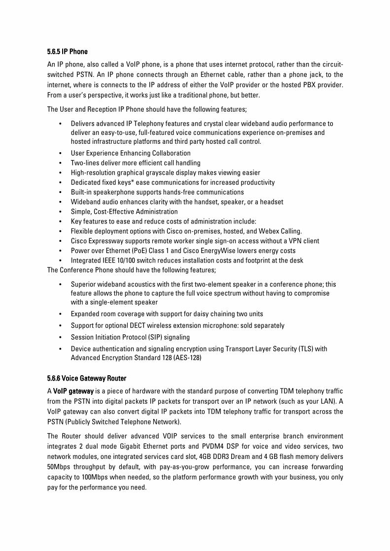
5.65.65.65.6.5 .5 .5 .5 IP Phone IP Phone IP Phone IP Phone
An IP phone, also called a VoIP phone, is a phone that uses internet protocol, rather than the circuit-
switched PSTN. An IP phone connects through an Ethernet cable, rather than a phone jack, to the
internet, where is connects to the IP address of either the VoIP provider or the hosted PBX provider.
From a user’s perspective, it works just like a traditional phone, but better.
The User and Reception IP Phone should have the following features;
• Delivers advanced IP Telephony features and crystal clear wideband audio performance to
deliver an easy-to-use, full-featured voice communications experience on-premises and
hosted infrastructure platforms and third party hosted call control.
• User Experience Enhancing Collaboration
• Two-lines deliver more efficient call handling
• High-resolution graphical grayscale display makes viewing easier
• Dedicated fixed keys* ease communications for increased productivity
• Built-in speakerphone supports hands-free communications
• Wideband audio enhances clarity with the handset, speaker, or a headset
• Simple, Cost-Effective Administration
• Key features to ease and reduce costs of administration include:
• Flexible deployment options with Cisco on-premises, hosted, and Webex Calling.
• Cisco Expressway supports remote worker single sign-on access without a VPN client
• Power over Ethernet (PoE) Class 1 and Cisco EnergyWise lowers energy costs
• Integrated IEEE 10/100 switch reduces installation costs and footprint at the desk
The Conference Phone should have the following features;
• Superior wideband acoustics with the first two-element speaker in a conference phone; this
feature allows the phone to capture the full voice spectrum without having to compromise
with a single-element speaker
• Expanded room coverage with support for daisy chaining two units
• Support for optional DECT wireless extension microphone: sold separately
• Session Initiation Protocol (SIP) signaling
• Device authentication and signaling encryption using Transport Layer Security (TLS) with
Advanced Encryption Standard 128 (AES-128)
5.65.65.65.6.6 .6 .6 .6 Voice Gateway RouterVoice Gateway RouterVoice Gateway RouterVoice Gateway Router
A VoIP gatewayVoIP gatewayVoIP gatewayVoIP gateway is a piece of hardware with the standard purpose of converting TDM telephony traffic
from the PSTN into digital packets IP packets for transport over an IP network (such as your LAN). A
VoIP gateway can also convert digital IP packets into TDM telephony traffic for transport across the
PSTN (Publicly Switched Telephone Network).
The Router should deliver advanced VOIP services to the small enterprise branch environment
integrates 2 dual mode Gigabit Ethernet ports and PVDM4 DSP for voice and video services, two
network modules, one integrated services card slot, 4GB DDR3 Dream and 4 GB flash memory delivers
50Mbps throughput by default, with pay-as-you-grow performance, you can increase forwarding
capacity to 100Mbps when needed, so the platform performance growth with your business, you only
pay for the performance you need.

5.65.65.65.6.7 .7 .7 .7 Wireless ControllerWireless ControllerWireless ControllerWireless Controller
The Wireless Controller provides centralized control, management, and troubleshooting for small to
medium-sized enterprises and branch offices.
It offers flexibility to support multiple deployment modes in the same controller—a centralized mode
for campus environments, FlexConnect® mode for lean branches managed over the WAN, and a mesh
(bridge) mode for deployments in which full Ethernet cabling is unavailable.
real-time communications between access points
optimized for 802.11ac Wave 2 performance, high scale, and enhanced system uptime.
Intent-driven programmability and streaming telemetry.
Quiet operation, with a small form factor and compact design ideal for space-constrained
deployments, providing flexibility without compromising on features.
Subsecond access point and client failover for uninterrupted application availability.
Extraordinary visibility into application traffic, using Application Visibility and Control (AVC), the
technology that includes the Network-Based Application Recognition 2 (NBAR2) engine, with Deep
Packet Inspection (DPI) capability. An embedded wireless Bring-Your-Own-Device (BYOD) policy
classification engine that allows classification of client devices and application of user group policies.
Guest access and Bonjour and Chromecast services in centralized deployments.
Software-defined segmentation with TrustSec® technology, reducing Access Control List (ACL)
maintenance, complexity, and overhead.
Integrated CleanAir® technology, providing the industry’s only self-healing and self-optimizing
wireless network.
A simplified GUI wizard for quick setup and intuitive dashboards for monitoring and troubleshooting.
5.65.65.65.6.8 .8 .8 .8 Video Conference SolutionVideo Conference SolutionVideo Conference SolutionVideo Conference Solution
Video conferencing is the technology that allows you to hold meetings with several correspondents
who are located in different places while seeing and talking to them in real time. It is different from
simple video calling, which is normally one-to-one video communication.
The intangible benefits of video conferencing include more efficient meetings with the exchange of
non-verbal communications and a stronger sense of community among business contacts, both within
and between companies, as well as with customers. On a personal level, the face-to-face connection
adds non-verbal communication to the exchange and allows participants to develop a stronger sense
of familiarity with individuals they may never actually meet in person.
The video conferencing system should be certified with Skype for Business and Office 365, making it
easy to connect without changing the way you work. The Skype interface is instantly familiar for an
intuitive experience that needs no training.
The conference solution should support 1080p60 video resolution, adding a new level of clarity and
realism to your business communications. Content can be sent and received in up to 1080p60 quality,
and it’s easy to share using the HDMI or VGA connections or wirelessly from your laptop or mobile
device.
The conference camera should deliver excellent 1080p image quality and is optimized for smaller
groups. In many smaller rooms participants sit closer to the camera, which can make it difficult to
capture everyone in view. The camera should feature a powerful optical zoom and optional wide-angle
lens to overcome these challenges, along with an advanced sensor that captures incredible detail and
brilliant image quality.
5.65.65.65.6.9 .9 .9 .9 Access PointAccess PointAccess PointAccess Point
In computer networking, a wireless access point (WAP), or more generally just access point (AP), is
a networking hardware device that allows other Wi-Fi devices to connect to a wired network. The AP
usually connects to a router (via a wired network) as a standalone device, but it can also be an
integral component of the router itself. An AP is differentiated from a hotspot, which is the physical
location where Wi-Fi access to a WLAN is available.
The access points go beyond getting ready for the new standard, providing the ultimate in flexibility
and versatility.
For large enterprise organizations that rely on Wi-Fi to engage with customers, the AP should be
intelligent enough to make decisions based on end-device activities and usage. This automation
allows you to devote time to other pressing matters, secure in the knowledge that your Wi-Fi network
is performing to its utmost potential.
The Access Point should have the following features;
• delivers new 802.11ac Wave 2 standard
• 802.11ac Beamforming
• 20-, 40-, 80, 160-MHz channels
• PHY data rates up to 5.2 Gbps
• Packet aggregation: A-MPDU (Tx/Rx), A-MSDU (Tx/Rx)
• 802.11 DFS
• 1024 MB DRAM
• 256 MB flash
• provides internal antenna and E regulatory domain.
• 4x4 MU-MIMO with three spatial streams
5.65.65.65.6.10 .10 .10 .10 Rack ServerRack ServerRack ServerRack Server
The Rack Server is among the most versatile general-purpose enterprise infrastructure and
application servers in the industry. It is a high-density 2-socket rack server that delivers industry-
leading performance and efficiency for a wide range of workloads, including virtualization,
collaboration, and bare-metal applications. The Rack Servers can be deployed as standalone servers.
The Cisco server extends the capabilities of the UCS portfolio in a 1-Rack-Unit (1RU) form factor. It
incorporates the Intel® Xeon® Scalable processors, supporting up to 20 percent more cores per
socket, twice the memory capacity, 20 percent greater storage density, and five times more PCIe
NVMe Solid-State Disks (SSDs) compared to the previous generation of servers. These improvements
deliver significant performance and efficiency gains that will improve your application performance.

The C220 M5 delivers outstanding levels of expandability and performance in a compact package,
with:
Latest Intel Xeon Scalable CPUs with up to 28 cores per socket
Up to 24 DDR4 DIMMs for improved performance
Up to 10 Small-Form-Factor (SFF) 2.5-inch drives or 4 Large-Form-Factor (LFF) 3.5-inch drives (77 TB
storage capacity with all NVMe PCIe SSDs)
Support for 12-Gbps SAS modular RAID controller in a dedicated slot, leaving the remaining PCIe
Generation 3.0 slots available for other expansion cards
Modular LAN-On-Motherboard (mLOM) slot that can be used to install a Cisco UCS Virtual Interface
Card (VIC) without consuming a PCIe slot
Dual embedded Intel x550 10GBASE-T LAN-On-Motherboard (LOM) ports

5.7 5.7 5.7 5.7 AUDIO VISUAL SYSTEMAUDIO VISUAL SYSTEMAUDIO VISUAL SYSTEMAUDIO VISUAL SYSTEM
a) Provide a detailed proposed technical solution for the AV systemdetailed proposed technical solution for the AV systemdetailed proposed technical solution for the AV systemdetailed proposed technical solution for the AV system of the building.
b) Supply, install, test and commission AV and meeting room booking system to the building in
accordance with the specifications.
c) Configure and set up the AV system to integrate with other related systems in the building.
d) Provide the test results, warranty certificate, reports and as installed drawings
PARTICULAR SPECIFICATIONS FOR CABLINGPARTICULAR SPECIFICATIONS FOR CABLINGPARTICULAR SPECIFICATIONS FOR CABLINGPARTICULAR SPECIFICATIONS FOR CABLING
a.a.a.a. IntroductionIntroductionIntroductionIntroduction
The project comprises the supply and installation of a structured telecommunications cabling
system.
A backbone network shall be installed within the building. Not all IP-based services will run on the
different physical networks. These services include:
• Corporate network
• Customs network
• Tenant network
• Voice traffic (IP phones)
• Wireless network
• Access control system.
• Security system
The detail design shall consider a cost-effective installation, allowing multi-use of physical layers
where appropriate. To ensure data security between the different services, Virtual networks or
VLANs will be configured. All access VLANs will be routed by core switches however; physical
network infrastructure will be shared.
b.b.b.b. RegulationsRegulationsRegulationsRegulations
This design shall comply with the latest revisions and amendments as at the date of submission of
the following:
• Relevant British Standards
• The Electronic Power Act
• The Communications Commission of Kenya (CCK)
• Kenya Bureau of Standards
• Institute of Electronic and Electrical Engineers (IEEE)
• The Asynchronous Transfer Mode (ATM)
• The International Standards Organisation (ISO)
• Institution of Electrical Engineers (I.E.E) Wiring Regulations
• Current recommendation of CCITT and CC1R

• ANSI/TIA/EIA
c.c.c.c. Labelling of cables, faceplates and interconnecting hardwareLabelling of cables, faceplates and interconnecting hardwareLabelling of cables, faceplates and interconnecting hardwareLabelling of cables, faceplates and interconnecting hardware
• Horizontal and backbone cables shall be labelled at each end. The cable or its
label shall be marked with its identifier.
• A unique identifier shall be marked on each faceplate to identify it as connecting
hardware.
• Each port in the faceplate shall be labelled with its identifier.
• A unique identifier shall be marked on each piece of connecting hardware to
identify it as connecting hardware.
• Each port on the connecting hardware shall be labelled with its identifier.
d.d.d.d. Working drawingsWorking drawingsWorking drawingsWorking drawings
A full set of all the working drawing shall be supplied by the contractor to the engineer for approval
showing the locations of and identifiers for:
• All Horizontal cable routing and terminations.
• All Telecommunications outlets/connectors
• All Backbone cable routing and terminations
e.e.e.e. RecordsRecordsRecordsRecords
All records shall be created by the installation contractor and turned over to the engineer at the
completion of work. The format shall be computer based and both soft copies and hard copies shall
be part of the As-built package.
The minimum requirements include:
• Cable records must contain the identifier, cable type, length termination
positions at ends, manufacturer, and part number.
• Connecting hardware records must contain the identifier, type of hardware and
the amount of positions.
• Connecting hardware positions records must contain the identifier, type of
position, and the cable identifier attached to it.
• Test documentation on all cable types shall be included as part of the As-built
package.
f.f.f.f. ReportsReportsReportsReports
All reports shall be generated from the computer-based programme used to create the records
above. These reports should include but not limited to: -

• Cable reports
• Cross-Connect Reports
• Connecting Hardware Reports
g.g.g.g. TestingTestingTestingTesting
Testing of cable channels shall be performed prior to system hand-over.
• Copper testingCopper testingCopper testingCopper testing
All UTP/SeTP horizontal cables and backbone cables whose length does not exceeding 90M (295 ft)
shall be tested according to ANSI/TIA/EIA-TSB-67 for wire map, attenuation, length, NEXT (Near
End Crosstalk Loss), and SeTP shall have an additional test for shield continuity. NEXT testing shall
be done in both directions
• Fibre optic testingFibre optic testingFibre optic testingFibre optic testing
Fibre horizontal and backbone cables shall be 100% tested for length, polarity, and attenuation at
850MM or 1300MM for 62.5/125-micron cable in at least one direction. Length shall be tested using
an OTDR. The warranty offered shall be for link and/or channel coverage for horizontal and
backbone cables. The testing performed shall be done in accordance with the type of warranty
required.
h.h.h.h. WorkmanshipWorkmanshipWorkmanshipWorkmanship
All work shall be done in a workman like fashion of the highest standards and in accordance with
best practices in the telecommunications industry. All equipment and materials are to be installed
in a neat and secure manner, while cables are to be properly dressed.
i.i.i.i. Installer qualifications and trainingInstaller qualifications and trainingInstaller qualifications and trainingInstaller qualifications and training
The installer shall be fully conversant and capable in the cabling of low voltage applications such
as, but not limited to data voice and imaging network systems. The installer shall at minimum
possess the following qualifications: -
• Personnel trained and certified in the design/installation of structured cabling
system.
• Personnel trained and certified in fibre optic cabling, splicing, termination and
testing techniques. Shall show proof of current certification.
j.j.j.j. System warrantySystem warrantySystem warrantySystem warranty
A Twenty-Year System Warranty for the structured cabling system shall be provided for covering
applications and components on all passive telecommunications equipment and cables.

k.k.k.k. Technical requirementsTechnical requirementsTechnical requirementsTechnical requirements
The system offered and quoted shall incorporate all features and facilities listed in this
specification. The structured cabling system shall consist of the following sub-systems: -
• Horizontal Sub-System
• Work Area Sub-System
• Backbone System
• Equipment Sub-System
The system shall support telephony and low voltage networks associated with analogue and digital
voice, data, local area networks (LAN) and imaging applications.
l.l.l.l. Horizontal cablingHorizontal cablingHorizontal cablingHorizontal cabling
The Horizontal Sub-System is the porting of the telecommunications cabling system that extends
from the work area telecommunications outlet/connector to the floor distributor in the wiring closet.
It consists of the telecommunications outlet/connector, horizontal cables, and that portion of the
cross-connect in the telecommunications closet serving the horizontal cable. Each floor of the
building shall be served by its own horizontal sub-system.
m.m.m.m. Cable typesCable typesCable typesCable types
All UTP/SeTP cables shall conform to ANSI/TIA/EIA-568-A Commercial Building
Telecommunications Cabling Standard and ISO/IEC 11801 (International) generic cabling for
customer premises standard. The following cable specifications shall also be met by the cable
manufacturer for copper 4 pair UTP/SCTP category 6 cables.
UTP cables shall: -
• be 100 Ω 4-pair, category 6 cable
• be appropriate for the environment in which it is installed
• Meet the requirements of ANS/TIA/EIA-568-A and ISO/IEC11801 meet the same
transmission requirements of UTP as specified in ANSI/TIA/EIA-568-A and ISO
9001 and 9002 Certified Manufacturer.
• Be categorised using power sum testing and meet the hybrid cable requirements
for use in horizontal cabling.
n.n.n.n. Cable routingCable routingCable routingCable routing
All horizontal cables, regardless of media type, shall not exceed 90M (295 ft) from the
telecommunications outlet in the work area to the floor distributor located in the
Telecommunications cabinet. The combined length of jumpers, or patch cords and equipment
cables in the telecommunications closet and the work area should not exceed 10M (33 ft).

Two horizontal cables shall be routed to each work area. Both the horizontal cables connected to a
telecommunication outlet shall be 4-pair, 100 Ω Category 6, unshielded twisted-pair (UTP)/ Screen
twisted-pair SeTP.
Horizontal pathways shall be installed or selected such that the minimum bend radius of horizontal
cables is kept within manufacturer specifications both during and after installation.
In open ceiling cabling, cable supports shall be provided by means that are structurally independent
of the suspended ceiling, its frame work, or supports. These supports shall be spaced no more than
1.5 M (5 ft) apart.
Telecommunications pathways, spacers and metallic cables which run parallel with electric power
or lighting shall be installed with a minimum clearance of 50MM (2 in). 4-pair UTP cables shall be
run using a star topology from the telecommunications closet on each floor to every individual
telecommunications outlet. All cables routes shall be approved by the Engineer prior to installation
of the cabling.
The contractor shall observe the bending radius and pulling strength requirements of the 4-pair
UTP/SeTP cable during handling and installation.
Each run of UTP/SeTP cable between horizontal of the cross-connect in the telecommunications
closet and the telecommunications outlet shall not contain splices.
In the telecommunications closet where cable trays or cable racking area used, the contractor
shall provide appropriate means of cable management such as reusable colour odd hook and loop
cable managers (cable ties) to create a neat appearance.
In a false ceiling environment, a minimum of 3 inches (75MM) shall be observed between the cable
supports and the false ceiling. Continuous conduit runs installed by the contractor should not
exceed 30.5m (100 ft) or contain more than two (2) 90-degree bends without utilising appropriately-
sized pull boxes.
o.o.o.o. Work areaWork areaWork areaWork area
This section outlines specifications for the work areas equipment cords (patch cords) and
telecommunications outlets at the users work area. The connection between the
telecommunications outlet and the user equipment (computer/telephone) shall be achieved by
means of this subsystem.
i.i.i.i. Work area equipment cordsWork area equipment cordsWork area equipment cordsWork area equipment cords
The work area equipment cords shall meet or exceed the following criteria:
a)a)a)a) Copper modular equipment cords: category 6 patch cordsCopper modular equipment cords: category 6 patch cordsCopper modular equipment cords: category 6 patch cordsCopper modular equipment cords: category 6 patch cords
Category 6 modular equipment cords shall: -
• Be round and consist of eight insulated 24 AWG, stranded copper conductors,
arranged in four colour-coded twisted pairs within a flame-retardant jacket.
• Be equipped with modular 8-position (RJ-45 style) plugs on both ends, wired
straight-through with standards compliant wiring.

• Use modular plugs which exceed FCC 47-part 68 subpart F and IEC 603-7
specifications and have 50 microinches of gold plating over nickel contracts.
• Maintain shield continuity through the modular plug shield not via the contracts
when screened (SeTP) cords are used.
• Modular cords shall include a moulded strain relief boot.
• be available in any custom length and standard length of 0.9, 1.5, 2.1, 4.5, 6, 7.6
metres
•
Electrical Specifications
• Have a DC resistance per lead 9.38Ω/100 mm maximum
• Have a mutual capacitance 17 split (86) maximum
• Have a characteristic impedance: 100Ω 15% from 1 to 100 Mhz.
• be 100% transmission tested with laboratory gas network analysers for proper
performance up to 100mhz.Vendor shall guarantee cords are compatible with
category 6 links.
• be UL VERIFIED for TIA/EIA category 6 electrical performance
• be UL LISTED 1863
• be made by an ISO 9001 and 9002 Certified Manufacturer
• be constructed of high impact flame-retardant the thermoplastic
b)b)b)b) Telecommunications outlets (high density)Telecommunications outlets (high density)Telecommunications outlets (high density)Telecommunications outlets (high density)
All high-density telecommunications outlets for 100 Ω 22.26 AWG copper cable shall: -
• be available in black, white, grey, ivory and light ivory
• be 8 position/8-conductor with coherent pairing of IDC pins
• have available a gravity feed (45 degree angled) design
• provide universal application/multi-vendor support
• support industry standards for T568A or T568B wiring options on each individual
outlet
• allow installation from the front or rear of the faceplate and allow for the jack to
pass through the faceplate without re-termination
• beside-stackable for high density solutions
• allow termination without the use of special termination tools
• be available in a screened version for 100Ω SeTP cable
• be a protective, hinged or flexible door to protect the outlet from dust and other
airborne contaminants
• provide colour-coded, slide-icons available for circuit identification
• be constructed of high impact, flame retarded thermoplastic
• have, as an option, an outlet which can be mounted into an IEC 603-7 complaint
opening (keystone)
• be UL VERIFIED for TIA/EIA Category 6 electrical performance

• be UL listed 1863 and CUL C22.2 approved
• have Austel “C-Tick” A96/0399
• Made by an ISO 9001 and 9002 Certified Manufacturer
ii.ii.ii.ii. FaceplatesFaceplatesFaceplatesFaceplates
All faceplates shall:-
• be applicable to both fibre and copper applications
• have write on designation labels for circuit identification together with a clear
plastic cover.
• be available in single gang and double gang configurations
• have optional modular furniture adapters available
• have stainless steel options available
• be made by ISO 9001 and 9002 Certified Manufacturer.
a)a)a)a) TelecoTelecoTelecoTelecommunications outlets (surface mount) low profile outlets mmunications outlets (surface mount) low profile outlets mmunications outlets (surface mount) low profile outlets mmunications outlets (surface mount) low profile outlets All Surface Mount Information Outlets for 100 Ω 22-26, AWG shall: -
• utilise compliant pin technology 110 style insulation displacement connectors
(IDC) and allow the use of a 4-pair impact tool
• allow for a minimum of 200 re-terminations without signal degradation below
standards compliance limit
• have solid state construction for transmission performance
• utilise reactance balance pair technology to address data circuit applications
upto 100 mhz
• comply with ECCC FR 47 part 68 subpart F and ICE 603-7 specifications and have
50 microinches of gold plating over ticket contracts
• provide universal application multi-vendor support
• support industry standards for T568A or T568B wiring options
• allow removal from the front when mounted in place
• be available in single port, modular increments
• be UL VERIFIED for TIA/EIA category 6 electrical performance
• be UL LISTED 1863 and CSA C22.2 approved
• be made by an ISO 9001 and 9002 Certified Manufacturer.
b)b)b)b) Surface mount bSurface mount bSurface mount bSurface mount boxesoxesoxesoxes
All low profile, surface mount boxes, used for mounting surface mount information outlets shall:-
• be available in 1-, 2-, 4-, or 6- port versions
• be built-in cable management for both fibre and copper applications
• be available in black, white, grey, ivory and light ivory
• have at least three sides with breakouts and an opening in the base for cable or
trunking (raceway) entry
• provide for an optional spring-loaded shutter door for added protection from dust
and other airborne contaminants
• have a designed area for printed or adhesive labels for circuit identification
• have optional magnets which can be internally mounted
• have colour-coded, snap in icons for circuit identification size
• 1-port box shall not exceed 61.8mm width, 44.6mm length and 27.9mm height
• 2-port box shall not exceed 70.6mm width 66.3mm length and 27.9mm height
• 4-port box shall not exceed 90.6mm width, 11.55mm length and 27.9mm height
• 6-port box shall not exceed 101.6mm width, 165.1mm length and 27.9mm height
• be made by an ISO 9001 and 9002 Certified Manufacturer.
c)c)c)c) Multimedia telecommunications outlet housingsMultimedia telecommunications outlet housingsMultimedia telecommunications outlet housingsMultimedia telecommunications outlet housings
All Multimedia/ multi-user information outlets shall:
• be surface mounted
• be capable of housing SC and ST type connectors for fibre and/or 8 position/8
conductor modular jacks for 100Ω UTP/SeTP cable
• accommodate hybrid adapter units for ST to SC or SC to ST connections
• be capable of integrating fibre, UTP/SeTP, coax shield (STP) connectivity outlets
• be capable of accommodating up to 12 port of mixed media (fibre, UTP/SeTP,
coax or shield STP outlets simultaneously or up to 24 ports for fibre only
applications
• be capable of accommodating a splice try for fibre terminations
• have a hide way labelling system compliant with TIA/EIA - 606 administrative
standard
• allow for securing cover with screw for additional security
• have rear cable access and at least four sides breakouts for cable/trunking
(raceway) entry with strain relief points
• have storage capacity for at least 1 meter of fibre and 305mm for UTP slack
storage, while maintaining minimum bends radius requirements
• have a removal fibre management tray that allows copper and fibre slack to be
stored separately
• allow information outlets to pass through openings before and after termination
• have optional magnets which can be internally mounted

• have a low-profile design
• Be made by an ISO 9001 and 9002 Certified Manufacturer.
p.p.p.p. Telecommunications closetsTelecommunications closetsTelecommunications closetsTelecommunications closets
The Telecommunication closet is a floor serving facility. The Floor Distributor links the horizontal
sub-system and the backbone subsystem together. The Floor Distributor shall consist of rack
mounted wiring blocks or panels for termination of copper cables and rack mount interconnect
centres for fibre management panels/trays for the termination of optical fibres.
The telecommunications closet shall be sized to accommodate telecommunications equipment,
cable terminations and associated cross-connect.
Communication grounding/earthing and bonding shall be in accordance with Applicable codes and
regulations.
It is recommended that the requirements of IEC 1000-5-2 ANSIT/TIA/EIA-607, or both be observed
through the entire cabling system.
The telecommunications closet shall not be shared with building services that may interfere with
the telecommunications systems or be used for custodial services.
q.q.q.q. Copper termination patch panels (utp/setp)Copper termination patch panels (utp/setp)Copper termination patch panels (utp/setp)Copper termination patch panels (utp/setp)
The termination panels shall support category 6 applications and facilitate cross-connection and
inter-connection using modular patch cords. The panels shall be sized to fit an EIA standard 19 inch
relay rack.
i.i.i.i. Modular patch panelModular patch panelModular patch panelModular patch panel
The panel shall:-
• be made of block anodised aluminium in 16-, 24-, 28-, 32-, 48-, 64- and 96-port
configurations
• have cut outs to fit the variety of information outlets used at the work area,
supporting UTP, SeTP and ST fibre adapters, as well as coaxial applications
• have cut outs which allow terminated jacks to pass through the panel for easy
rearrangement
• be available in two sizes for each port quality to allow for custom administration
of the network
• be changeable ports which are removed from the front of the panel to allow
custom configuration or modification to the panel
• be available with no ports to act as a filler between rack hard ward and
equipment

• have port identification numbers provide on both the front and the rear of the
panel
• have mounting slots compatible with ANS/EIA-310
• accept 110-style patch plugs as a means of termination
• electrical specifications
• be consistent with the electrical specifications of the work area outlets specified
in sections 4.1. 33.2.1 And 4.3.2.2 above be made by an ISO 9001 and 9002
Certified Manufacturer.
ii.ii.ii.ii. Modular patch panel (high density)Modular patch panel (high density)Modular patch panel (high density)Modular patch panel (high density)
The panel shall:
• be made of black, light weight, high strength brushed aluminium in 24-, 48-port
configuration
• have openings to fit the variety of information outlets ousted in the work area-
supporting UTP, SeTP and ST fibre adapters, as well as coaxial applications,
• Each opening can handle four or six jack modules
• have openings which allow terminated jacks to pass through panel for easy
rearrangement
• have port identification numbers on both the front and rear of the panel
• provide for proper termination and grounding/earthing of 100Ω SeTP cable
• Accommodate at least 24 ports for each rack mount space (1rms) = 44.5mm
(1.75in.)
• be available with an integrated rear management bar
• be provided with self-adhesive, clear label holders and white designation labels
• be available with no ports to act as a filter between rack hardware and
equipment
• have mounting slots compatible with ANSI/EIA-310
Electrical specifications:
• be consistent with the electrical specifications of the work area outlets specified
• Be made by an ISO 9001 and 9002 Certified Manufacturer.
r.r.r.r. Fibre optic interconnect centres, panels and traysFibre optic interconnect centres, panels and traysFibre optic interconnect centres, panels and traysFibre optic interconnect centres, panels and trays
All interconnect trays (units) shall provide cross-connect, inter-connect, splicing capabilities and
contain cable management for supporting and routing the fibre cables/jumpers.
i.i.i.i. RackRackRackRack----mounted, high density fibre interconnect centremounted, high density fibre interconnect centremounted, high density fibre interconnect centremounted, high density fibre interconnect centre

• be available in white or black and occupy no more than four rack mount spaces
4 rms = 177.8mm (7.00 in.) and accommodate up to 72 ST or 144 SC fibres using
snap-in pre-loaded adapter plates
• accommodate hybrid adapter bezel for ST to SC or SC to St connections
• have fibre cable managers to effectively store fibre cable slack and comply with
fibre bend radius requirements
• have six port fibre adapter plates which allow for colour coding connectors
• have fibre adapter plates with snap-in installation and one-finger removal
• have lockable front and rear transparent doors that have spring release hinges
for removal
• accommodate stackable splice trays which manage a total of 72 splices
• have an adapter plate mounting bracket which slides out to the front and to the
rear of the unit for increased access
• have cable access points for fibre jumpers entering and exiting the unit with
rotating grommets to facilitate cable loading and to minimise micro bending
stress
• have anchor points for fibre cables (s) entering the unit
• have labelling which meets or exceed ANSI/TIA/EIA-606 requirements and also
be laser printable
• be able to mount to a standard 19 inch cabinet
• be UL LISTED 1863 and CUL C22.2 approved
• Be made by an ISO 9001 and 9002 Certified Manufacturer.
ii.ii.ii.ii. RackRackRackRack----mounted, low profile fibre connect panelmounted, low profile fibre connect panelmounted, low profile fibre connect panelmounted, low profile fibre connect panel
The low fibre connect panel shall:
• Not be bigger than one rack mount space and accommodate up to -32SC or ST
adapters;
• Accommodate hybrid adapter bezels for ST to SC or SC to ST connections;
• Be provided with strain relief lugs for the fibre cable entering the unit from the
slide or back.
s.s.s.s. Patch corPatch corPatch corPatch cordsdsdsds
Where applicable, the contractor shall supply patch cords (factory assembled plug ended jumpers)
for patch panel and terminal blocks.
i.i.i.i. RJRJRJRJ----45 45 45 45 –––– RJRJRJRJ----45 Patch cords: category 645 Patch cords: category 645 Patch cords: category 645 Patch cords: category 6
Category 6 modular patch/equipment cords shall:
• be round and consist of eight insulated 24AWG, stranded copper conductors,
arranged in four colour-coded twisted pairs within a flame-retardant jacket
• be equipped with modular 8 position (RJ-45 style) plugs on both ends, wired
straight-through with standards compliant wiring
• use modular plugs which exceed ECC CFR 47 part 68 subpart F and IEC 603-7
specifications and have 50 micro inches of gold plating over nickel contracts
• shall maintain shield continuity through the modular plug shield not via te
contracts when screened (SeTP) cords are used
• modular cords should include a moulded strain relief boot
• be available in standard lengths of 1.5 and 3meters
Electrical specifications
• have a DC resistance per lend: 9.38Ω/100m maximum
• have a mutual capacitance: 17.5 pF/ft (5.6pF/m) maximum
• have a characteristic impedance: 100Ω 15% from 1 to 100mhz
• be 100% transmission tested with laboratory grade network analysers for proper
Category 6 links
• be UL VERIFIED for TIA/EIA Category 6 electrical performance
• be UL LISTED 1863
• be made by an ISO 9001 and 9002 Certified Manufacturer.
ii.ii.ii.ii. Fibre equipment/patch cords (jumpers)Fibre equipment/patch cords (jumpers)Fibre equipment/patch cords (jumpers)Fibre equipment/patch cords (jumpers)
The fibre equipment patch cords shall:-
• be available in standard lengths of 1, 3 and 5 meters
• custom lengths shall also be available and shall meet or exceed standards as
defined in ANSI/TIA/EIA-568-A and ISO/IEC 11801
• utilise simplex or duplex fibre cable that is 62.5/125 MICRON multimode, OFNR
riser grade and meets the requirements of UL 1666
• attention shall not exceed 3.5 bB/km @350mm wavelength of 1.0 Db/km
@1300mm
• cable packet colour shall be orange. The connectors shall be SC or ST in
accordance with TIA/EIA-568-A and must include a ceramic ferrule
• ST connectors must have a metal coupling nut
• terminated connectors shall exhibit a maximum insertion loss of 0.75dB with an
average of 0.50 dB when tested at either 850mm or 1300mm wavelengths
• be made by an ISO 9001 and 9002 Certified Manufacturer
• be UL 166 approved

iii.iii.iii.iii. Single mode fibre patch cordsSingle mode fibre patch cordsSingle mode fibre patch cordsSingle mode fibre patch cords
All single mode fibre optic patch cords shall:-
• be either simplex or duplex OFNR riser grade cable, with attenuation at
wavelength 1310mm being 1.0 dB/km and at wavelength 1550mm 1.0dB/km
• have a yellow jacket
• be terminated with ceramic tip connectors in either the standards based SC or
ST style. These connectors shall have a maximum attenuation of 0.5dB and a
minimum return loss of 40dB
• be made by an ISO 9001 and 9002 Certified Manufacturer
• be UL 1666 approved
t.t.t.t. Standard floor distribution frameStandard floor distribution frameStandard floor distribution frameStandard floor distribution frame
For rack mounted installations in a telecommunications closet the installer shall use a 19in x 7ft
rack. The rack shall:
• have 76mm by 152mm vertical cable channels as side rails
• have channels capable of utilising and re-locating up to ten re-usable hook and
loop cable managers
• have ten high capacity cable managers provided for the front of the rack which
can be used for horizontal or vertical cable management and easily twist and
lock into place without the use of screws or tools
• have standard ANSI/EIA-310-C mounting holes and cable routing openings in the
front, rear and size of the channels
• be made of aluminium with a black finish and utilise black grommets for unused
cable openings
• have two optional vertical cable management channels 153mm (6in.) x 2.1mm
(7ft) and 76mm (3in.) x 2.1m (7ft) which can be located between racks. The
channel shall include cable retainers which can be hinged left or right and be
located in any position along the channel
• have floor mounting holes and a ground lug for 0.6 gauge ground cable provided
• be made by an ISO 9001 and 9002 Certified Manufacturer.
u.u.u.u. Wall mounting brackWall mounting brackWall mounting brackWall mounting bracketsetsetsets
Wall brackets shall:-
• be constructed as a single piece

• be available in 2,3,4 and 6 rack mount spaces, but be designed in 1 rms
increments to accept 1 rms panels
• be hinged on one side with standard ANSI/EIA-310-C mounting holes
• mount standard 19 inch patch panels
• mount with the hinge to the right or the left
• be able to mount to a standard 19 inch rack
• have a cable access hole in the rear support
• be 150mm (6 in.) deep
• be made by an ISO 9001 and 9002 Certified Manufacturer
v.v.v.v. Backbone cablingBackbone cablingBackbone cablingBackbone cabling
These are cables connecting closet to closet or closet to the equipment room within the building.
The following cables are allowed for use in as backbone: 4 pair 100 Ω unshielded/screened twisted-
pair. 100Ω UTP multi-pair copper cables and 62.5/125 micron multimode Optical fibre cables. The
cable shall support voice, data and imaging applications. The bending radius and pulling strength
requirements of all backbone cables shall be observed during handing and installation.
Building Backbone subsystem shall act as the convergence point for all the telecommunications
closets. It shall consist of the backbone transmission media between the telecommunications
closets and the server room. The building shall be connected to the incoming telecommunications
services through the core routing switch located in the server room.
w.w.w.w. InstallationInstallationInstallationInstallation
i.i.i.i. Site surveySite surveySite surveySite survey
Prior to placing any cable pathways or cable, the contractor shall survey the site to determine job
conditions will not impose any obstructions that would interfere with the safe satisfactory
placement of the cables and to arrange the removal of any obstructions with the Engineer
accordingly.
ii.ii.ii.ii. Cable pathwaysCable pathwaysCable pathwaysCable pathways
Pathways shall be designed and installed to meet Applicable Local and National Building and
Electrical Codes or Regulations.
Ground/Earth and bonding of pathways shall comply with applicable codes and regulations.
Pathways shall not have exposed sharp edges that may come into contract with
telecommunications cables.
The number of cables placed in a pathway shall not exceed manufacture specifications, nor will the
geometric shape of a cable be affected.

Pathways shall not be located in elevator shafts.
iii.iii.iii.iii. Cable routes and clearancesCable routes and clearancesCable routes and clearancesCable routes and clearances
Horizontal distribution cables shall not be exposed in the work area or other locations with public
access.
Cables routed in a suspended ceiling shall not be draped across the ceiling tiles. Cable supports
shall be mounted a minimum of 75mm above the ceiling grid supporting tiles.
Cables supports in a suspended ceiling shall be structurally independent of the suspended ceiling,
its framework or support and not be spaced more than 1.5m apart.
The installations of telecommunications cabling shall maintain a minimum clearance of 3m from
power cables in excess of 180 Vrms.
No telecommunications cross connects shall be physically located within 6m of electrical
distribution panels, step down devices or transformers which carry voltages in excess of 480 Vrms.
Minimum separation of 50mm (2ft) shall be provided in areas where power or electric light circuits
which are equal to or less than 480 Vrms and telecommunications cabling coexist.
iv.iv.iv.iv. Work area terminationWork area terminationWork area terminationWork area termination
All UTP/SeTP cables wired to the telecommunications outlet/connector shall have 4-pair terminated
in eight-position, not keyed modular outlets in the work area. All pairs shall be terminated.
The telecommunications outlet/connector shall be securely mounted at planned locations.
The height of the telecommunications faceplates shall be next to a device unless otherwise
specified.
The maximum cable pulling tensions shall not exceed manufacturer’s specifications.
The maximum cable bend radius shall not exceed the manufacturer’s specifications.
In spaces with UTP/SeTP cable termination, the maximum bending radius for 4-pair cable shall not
exceed four times outside diameter of the cable and ten times for multi-pair cable. This shall be
done unless this violates manufacturer specifications.
During the actual installation, bend radius on 4-pair cable shall not exceed eight times the outside
diameter of the cable and ten times for multi-pair cable. This shall be done unless this violates
manufacturer specifications.
v.v.v.v. SlackSlackSlackSlack
In the work area, a minimum of 300mm shall be left for UTP/SeTP, while 1000m shall be left for fibre
cables.
In telecommunications closets a minimum of 3m of slack shall be left for all cables. This slack must
be neatly managed on trays or other support types.
x.x.x.x. Infrastructure managementInfrastructure managementInfrastructure managementInfrastructure management
An intelligent infrastructure management system shall be installed for the system. The system shall
have a windows-based interface. The proposed system should be able to track and log all the
changes undertaken on the system in the operational phase.
y.y.y.y. Network control equipmentNetwork control equipmentNetwork control equipmentNetwork control equipment
• Active devices used at the LAN edge shall have 24 or 48 ports for connection to
the horizontal cabling.
• Active devices shall be rack mounted.
• Active devices for horizontal cabling shall support auto sensing 10/100mbps and
backbone cabling at 1000mbps.
• Active devices used at aggregation layer of LAN shall support IP routing.
• Active devices used at the LAN edge must be stackable and shall attach to the
backbone cabling at 1000mbps.
• Where more than one active device is required to satisfactorily serve the floor
data outlets distribution requirements they shall be stacked using interface
operating at the backbone speed.
z.z.z.z. Ethernet floor edge switchesEthernet floor edge switchesEthernet floor edge switchesEthernet floor edge switches
• The edge switch connecting to the backbone must include at least two ports of
1000 Base X Gigabit Ethernet with GBIC support, QOS, Multiple queues with
weighted round robin (WRR) scheduling and layer 3 switching and routing of IP,
IPX and IP multicast traffic.
• The switch in the set up should give 10/100/1000MBPS at the desktop.
• Should support at least 16,000 MAC Addresses
• The switch should be adequate to cater for the total number of data points.
• Advanced IP Switching
• Stackable to up to 8 units
• Up to 8 queues per port with prioritisation
• At least 9.5 MB throughput
• Redundant power supply
• Support for up to 512 Virtual router interface
• At least 16K MAC Table
• Support Centralised management via SNMP

a.a.a.a. Ethernet core routing switchesEthernet core routing switchesEthernet core routing switchesEthernet core routing switches
The following are the minimum requirements for the core routing switch:
• The Backbone switch should provide minimum (10/100/1000/10000) of 12 ports of
IEEE802.32 1000 Base X.
• Be able to run industrial standard IP multi cast at wire speed.
• Chassis should support a minimum of 8 Slots
• Non-blocking integrated layer 2/3/4 switching performance.
• Multi-layer IOS software services with IP routing, advanced QOS, traffic
management and comprehensive security.
• Shall be rack mounted in standard rack/cabinets.
• Shall have a redundant power supply for each edge switch connecting to the
backbone.
• Shall support standard security features.
• Up to 8 queues per port with prioritisation
• At least 9.5 MB throughput
• Redundant power supply
• Support for up to 512 Virtual router interface
• At least 16K MAC Table
• At least 4096 VLANS support
• Dual power supply
• MPLS Packet Switching
b.b.b.b. DTU’SDTU’SDTU’SDTU’S
Type: HDSL
Max Data Transfer Rate: 2Mbps
Mode of Operation: DCE
Connector: DB37
Interface Cable: DB37-DB15
a.a.a.a. Router SpecificationsRouter SpecificationsRouter SpecificationsRouter Specifications
Memory: 256MB expandable to 512MB

Flash Memory: 64MB
Interfaces: 2 x Fast Ethernet LAN Ports
1 x Serial WAN Port
Auxiliary Port
Console Port
Expansion Slots: 1 Network Module Slot
Software: Latest Software release
Installation: Standard 19" Rack Mount Kit
b.b.b.b. Network cabinetsNetwork cabinetsNetwork cabinetsNetwork cabinets
• The cabinet shall be metallic with front clear glass and of good finish and
conveniently accessible by technical personnel for maintenance.
• Power to the cabinet shall be switched off/on from within the cabinets. Proper
power socket cables to be supplied within the cabinet.
• The cabinets to be used in this installation shall conform to ANSI/TIA/EIA-568B
with forced cooling and their location shall be determined on site.
• Support small factor pluggable (SFP) and industry leading density up to 240 of
IEEE 8033 for 1000 Base-SX ports per system.

B.B.B.B. Particular Instructions For Pricing of Items in the Bills of Quantities Particular Instructions For Pricing of Items in the Bills of Quantities Particular Instructions For Pricing of Items in the Bills of Quantities Particular Instructions For Pricing of Items in the Bills of Quantities
9.1 9.1 9.1 9.1 General DirectionsGeneral DirectionsGeneral DirectionsGeneral Directions
(a) The Bills of Quantities are to be read in conjunction with the Conditions of Contract, the
Technical Specification, the Data Schedules and the Drawings for details of the description,
quality, tests and strengths of materials to be used and the workmanship, conditions,
obligations, liabilities described in the Conditions of Contract, the Specification, the Data
Schedules and the Bills of Quantities including all overhead charges and profit and carrying
out of the Works shall be deemed to be spread over and included in the prices and sums in
this Bill of Quantities.
(b) Each item which the Tenderer proposes to supply shall be priced by Tenderer with the
exception of the item for which Provisional Sums have been allowed. The Tenderer shall
insert in the appropriate column against each item allocated in Kenya Shillings (Kshs.) as
required by him and payments shall be made according to this allocation in the event of a
contract.
If the Tenderer omits to price any item in the Bills of Quantities then the cost of such items will
be held to be spread over and included in the prices given for other items of work.
(c) The rate entered against each item shall be inclusiveshall be inclusiveshall be inclusiveshall be inclusive of all duties, customs and excise
charges. A separate section is included for VATVATVATVAT at the summary page.
(d) The Total of Tender for the electrical services shall be carried to the Main Summary section 6.
The Total of Tender for the electrical services shall include for the design, manufacture,
inspection and testing, packing for shipment, insurance, customs, dues, delivery to site,
unloading, and all other charges, complete erection, testing, setting to work, finishing,
painting, maintenance for a period of six calendar months and the instruction period all to the
satisfaction of the Engineer, of the items of Plant described or implied within the Specification
and shown on the Drawings.
(e) Provisional Sums may be expended in part, in whole or totally deleted from the Contract. The
Tenderer shall take this into consideration when pricing the tender as no claims for loss of
profit, etc will be entertained.
It shall be deemed that the contractor has included for all requirements contained within the
Specification, Drawings, Data Schedules and Bills of Quantities.
(f) For information and to assist the contractor in pricing the Bills of Quantities and the Schedule
of Rates, the following Scope of Contract have been included, these details having formed part
of the Main Tender Documents.
(g) Irrespective of the requirements contained within the East African Standard method of
Measurement it shall be deemed that the contractor has included all requirements contained
within the Specification, Drawings, Schedules and Bills of Quantities.
(h) It shall be the responsibility of the Tenderer to ensure that his prices include for all items
necessary to complete the installation whether or not the items have been specifically
identified within the Bills of Quantities. The Tenderer’s prices shall include for all nuts, bolts,
washers, fixings, supports and the like as necessary.

SECTIONSECTIONSECTIONSECTION 6666
ICT ICT ICT ICT InstallationsInstallationsInstallationsInstallations
Main Summary Main Summary Main Summary Main Summary
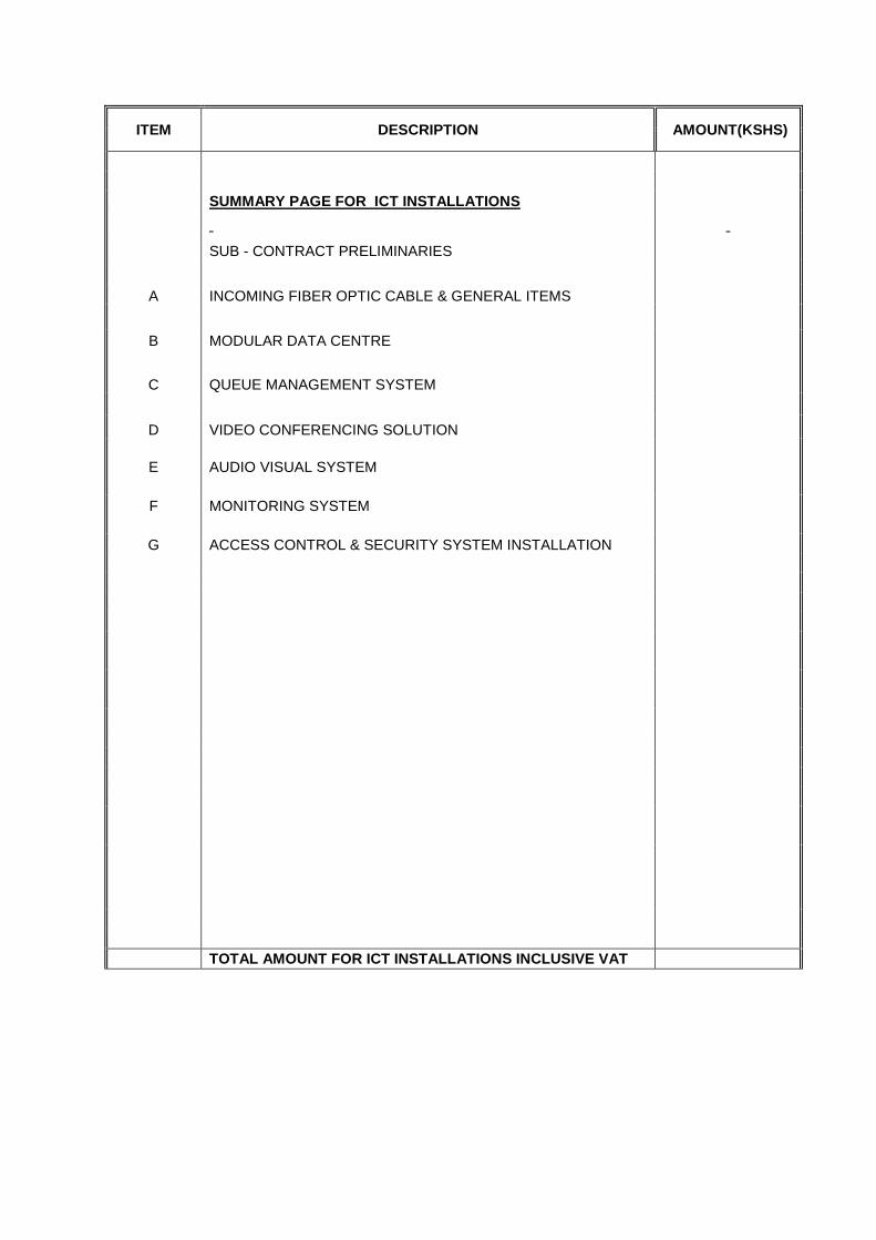
ITEM DESCRIPTION AMOUNT(KSHS)
SUMMARY PAGE FOR ICT INSTALLATIONS
SUB - CONTRACT PRELIMINARIES
A INCOMING FIBER OPTIC CABLE & GENERAL ITEMS
B MODULAR DATA CENTRE
C QUEUE MANAGEMENT SYSTEM
D VIDEO CONFERENCING SOLUTION E AUDIO VISUAL SYSTEM F MONITORING SYSTEM G ACCESS CONTROL & SECURITY SYSTEM INSTALLATION
TOTAL AMOUNT FOR ICT INSTALLATIONS INCLUSIVE VAT

SECTION 7SECTION 7SECTION 7SECTION 7
Data SchedulesData SchedulesData SchedulesData Schedules

DATA SCHEDULE A DATA SCHEDULE A DATA SCHEDULE A DATA SCHEDULE A ---- GENERALGENERALGENERALGENERAL
ItemItemItemItem
DescriptionDescriptionDescriptionDescription
ManufactureManufactureManufactureManufacture
rrrr
Name of Local AgentName of Local AgentName of Local AgentName of Local Agent
Delivery to Site in weeksDelivery to Site in weeksDelivery to Site in weeksDelivery to Site in weeks
1
2
3
4
5
6
7
8
9
10
11
Modular data centre
Active network
Unified communication
Open DNS
Server & software
Perimeter Security Tools &system firewalls.
Queue management equipment
Audio visual equipment
Video conferencing equipment
Security system installations
Any other items to be listed below or on an attached
sheet

DATA SCHEDULE B DATA SCHEDULE B DATA SCHEDULE B DATA SCHEDULE B –––– SPECIAL TOOLSSPECIAL TOOLSSPECIAL TOOLSSPECIAL TOOLS
The Tenderer shall list hereunder his recommended list of tools for the plant supplied under this
contract. The list shall be priced individually. A Provisional Sum is to be included in the Schedule of
Prices.
Item No.Item No.Item No.Item No. DescriptionDescriptionDescriptionDescription
Amount in Kshs.Amount in Kshs.Amount in Kshs.Amount in Kshs.
1 Modular data centre
2 Audio visual system
3 Video conferencing system
4 Data management equipment
To be listed below
Note: Tenderer to submit details of tools for which prices have been entered
Total for Special Tools Kshs._______________________________

DATA SCHEDULE C DATA SCHEDULE C DATA SCHEDULE C DATA SCHEDULE C –––– SPARSPARSPARSPARE PARTSE PARTSE PARTSE PARTS
The Tenderer shall list hereunder his recommended list of spares covering a period of one year for
the plant supplied under this Contract. The list shall be priced individually. A Provisional Sum is to
be included in the Schedule of Prices.
IteIteIteItem No.m No.m No.m No. DescriptionDescriptionDescriptionDescription Amount Kshs.Amount Kshs.Amount Kshs.Amount Kshs.
1.1.1.1.
2.2.2.2.
3.3.3.3.
4.4.4.4.
5.5.5.5.
6.6.6.6.
7.7.7.7.
8.8.8.8.
9.9.9.9.
10.10.10.10.
Total for Spare PartsTotal for Spare PartsTotal for Spare PartsTotal for Spare Parts Kshs.Kshs.Kshs.Kshs.
Note: Note: Note: Note: Tenderer to submit details of spare parts for which prices have been entered.
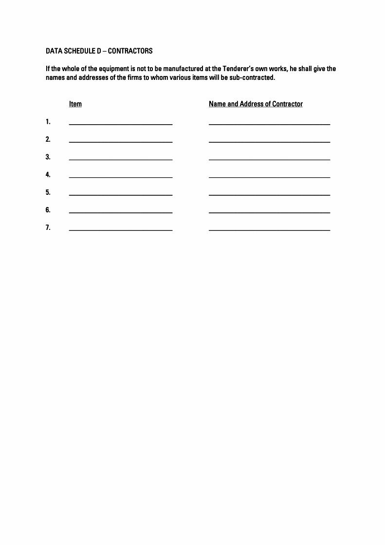
DATA SCHEDULE D DATA SCHEDULE D DATA SCHEDULE D DATA SCHEDULE D –––– CONTRACTORSCONTRACTORSCONTRACTORSCONTRACTORS
If the whole of the equipmeIf the whole of the equipmeIf the whole of the equipmeIf the whole of the equipment is not to be manufactured at the Tenderer’s own works, he shall give the nt is not to be manufactured at the Tenderer’s own works, he shall give the nt is not to be manufactured at the Tenderer’s own works, he shall give the nt is not to be manufactured at the Tenderer’s own works, he shall give the
names and addresses of the firms to whom various items will be subnames and addresses of the firms to whom various items will be subnames and addresses of the firms to whom various items will be subnames and addresses of the firms to whom various items will be sub----contracted.contracted.contracted.contracted.
ItemItemItemItem Name and Address of Name and Address of Name and Address of Name and Address of ContractorContractorContractorContractor
1.1.1.1. ____________________________________________________________________________________________________________________ ________________________________________________________________________________________________________________________________________
2.2.2.2. ____________________________________________________________________________________________________________________ ________________________________________________________________________________________________________________________________________
3.3.3.3. ____________________________________________________________________________________________________________________ ________________________________________________________________________________________________________________________________________
4.4.4.4. ____________________________________________________________________________________________________________________ ________________________________________________________________________________________________________________________________________
5.5.5.5. ____________________________________________________________________________________________________________________ ________________________________________________________________________________________________________________________________________
6.6.6.6. ____________________________________________________________________________________________________________________ ________________________________________________________________________________________________________________________________________
7.7.7.7. ____________________________________________________________________________________________________________________ ________________________________________________________________________________________________________________________________________

DATA SCHEDULE E DATA SCHEDULE E DATA SCHEDULE E DATA SCHEDULE E –––– MANUFACTURERS, PLACES OF ASSEMBLY, TESTING AND INSPECTIONMANUFACTURERS, PLACES OF ASSEMBLY, TESTING AND INSPECTIONMANUFACTURERS, PLACES OF ASSEMBLY, TESTING AND INSPECTIONMANUFACTURERS, PLACES OF ASSEMBLY, TESTING AND INSPECTION
ItItItItemememem ManufacturerManufacturerManufacturerManufacturer Place of ManufacturePlace of ManufacturePlace of ManufacturePlace of Manufacture Place of InspectionPlace of InspectionPlace of InspectionPlace of Inspection
and Testingand Testingand Testingand Testing
____________________________________________________________________________________________________________________________________________________________________________________________________________________________________________________________________________________________________________________________
1 Modular data centre
2 Audio visual system
3 Video conferencing system
4 Queue management system
5 Security system installation

DATA SCHEDULE F DATA SCHEDULE F DATA SCHEDULE F DATA SCHEDULE F –––– DELIVERIESDELIVERIESDELIVERIESDELIVERIES
The times to be entered below are the periods in weeks from the date of acceptance of the Tender in
the event of a Contract.
In the column headed “Method of Shipping”, the Tenderer is to state whether items are to be shipped
by sea or air and road or rail and whether as general cargo, in containers, etc. Each item of plant,
equipment or materials shall be entered.
Time of Time of Time of Time of
DespatchDespatchDespatchDespatch Shipping RouteShipping RouteShipping RouteShipping Route Method ofMethod ofMethod ofMethod of Time of Arrival on SiteTime of Arrival on SiteTime of Arrival on SiteTime of Arrival on Site
ItemItemItemItem ExExExEx----WorksWorksWorksWorks FromFromFromFrom ToToToTo ShippingShippingShippingShipping

SECTION SECTION SECTION SECTION 8888
DrawingsDrawingsDrawingsDrawings
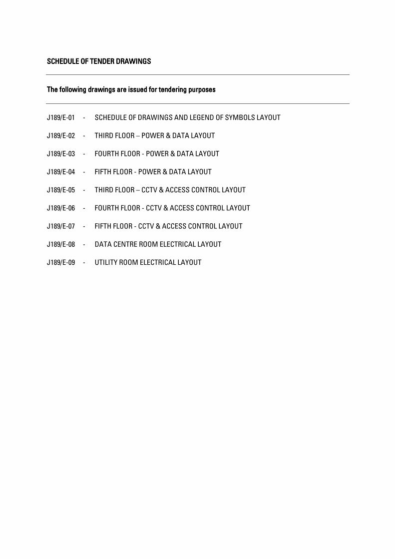
SCHEDULE OF TENDER DRAWINGSSCHEDULE OF TENDER DRAWINGSSCHEDULE OF TENDER DRAWINGSSCHEDULE OF TENDER DRAWINGS
The following drawings are issued for tendering purposesThe following drawings are issued for tendering purposesThe following drawings are issued for tendering purposesThe following drawings are issued for tendering purposes
J189/E-01 - SCHEDULE OF DRAWINGS AND LEGEND OF SYMBOLS LAYOUT
J189/E-02 - THIRD FLOOR – POWER & DATA LAYOUT
J189/E-03 - FOURTH FLOOR - POWER & DATA LAYOUT
J189/E-04 - FIFTH FLOOR - POWER & DATA LAYOUT
J189/E-05 - THIRD FLOOR – CCTV & ACCESS CONTROL LAYOUT
J189/E-06 - FOURTH FLOOR - CCTV & ACCESS CONTROL LAYOUT
J189/E-07 - FIFTH FLOOR - CCTV & ACCESS CONTROL LAYOUT
J189/E-08 - DATA CENTRE ROOM ELECTRICAL LAYOUT
J189/E-09 - UTILITY ROOM ELECTRICAL LAYOUT